JP2009072789A - Laser machining apparatus - Google Patents
Laser machining apparatusDownload PDFInfo
- Publication number
- JP2009072789A JP2009072789AJP2007241251AJP2007241251AJP2009072789AJP 2009072789 AJP2009072789 AJP 2009072789AJP 2007241251 AJP2007241251 AJP 2007241251AJP 2007241251 AJP2007241251 AJP 2007241251AJP 2009072789 AJP2009072789 AJP 2009072789A
- Authority
- JP
- Japan
- Prior art keywords
- laser
- optical axis
- processing apparatus
- light
- condensing
- Prior art date
- Legal status (The legal status is an assumption and is not a legal conclusion. Google has not performed a legal analysis and makes no representation as to the accuracy of the status listed.)
- Pending
Links
- 238000003754machiningMethods0.000titleabstractdescription4
- 230000003287optical effectEffects0.000claimsabstractdescription90
- 201000009310astigmatismDiseases0.000claimsabstractdescription27
- 238000012545processingMethods0.000claimsdescription195
- 238000009826distributionMethods0.000claimsdescription16
- 230000009471actionEffects0.000claimsdescription6
- 238000001816coolingMethods0.000claimsdescription6
- 230000001678irradiating effectEffects0.000abstractdescription3
- 239000004065semiconductorSubstances0.000description16
- 239000013307optical fiberSubstances0.000description10
- 239000011521glassSubstances0.000description8
- 238000010586diagramMethods0.000description7
- RYGMFSIKBFXOCR-UHFFFAOYSA-NCopperChemical compound[Cu]RYGMFSIKBFXOCR-UHFFFAOYSA-N0.000description5
- 229910052802copperInorganic materials0.000description5
- 239000010949copperSubstances0.000description5
- 230000000694effectsEffects0.000description5
- 230000008901benefitEffects0.000description4
- 230000008859changeEffects0.000description4
- 230000004048modificationEffects0.000description4
- 238000012986modificationMethods0.000description4
- 238000002310reflectometryMethods0.000description4
- 229910001220stainless steelInorganic materials0.000description4
- 239000010935stainless steelSubstances0.000description4
- 238000004381surface treatmentMethods0.000description4
- 238000005520cutting processMethods0.000description3
- 239000000835fiberSubstances0.000description3
- PCHJSUWPFVWCPO-UHFFFAOYSA-NgoldChemical compound[Au]PCHJSUWPFVWCPO-UHFFFAOYSA-N0.000description3
- 239000010931goldSubstances0.000description3
- 229910052737goldInorganic materials0.000description3
- 239000000463materialSubstances0.000description3
- 229910052751metalInorganic materials0.000description3
- 239000002184metalSubstances0.000description3
- 238000003466weldingMethods0.000description3
- CURLTUGMZLYLDI-UHFFFAOYSA-NCarbon dioxideChemical compoundO=C=OCURLTUGMZLYLDI-UHFFFAOYSA-N0.000description2
- 230000004075alterationEffects0.000description2
- 229910052782aluminiumInorganic materials0.000description2
- XAGFODPZIPBFFR-UHFFFAOYSA-NaluminiumChemical compound[Al]XAGFODPZIPBFFR-UHFFFAOYSA-N0.000description2
- 230000000903blocking effectEffects0.000description2
- 239000000919ceramicSubstances0.000description2
- 230000007423decreaseEffects0.000description2
- 230000006866deteriorationEffects0.000description2
- 238000000034methodMethods0.000description2
- 230000003647oxidationEffects0.000description2
- 238000007254oxidation reactionMethods0.000description2
- 238000007747platingMethods0.000description2
- 230000008569processEffects0.000description2
- 230000009467reductionEffects0.000description2
- 229910002092carbon dioxideInorganic materials0.000description1
- 239000001569carbon dioxideSubstances0.000description1
- 238000005553drillingMethods0.000description1
- 238000005259measurementMethods0.000description1
- 238000013021overheatingMethods0.000description1
- 230000002093peripheral effectEffects0.000description1
- XLYOFNOQVPJJNP-UHFFFAOYSA-NwaterSubstancesOXLYOFNOQVPJJNP-UHFFFAOYSA-N0.000description1
Images


Classifications
- G—PHYSICS
- G02—OPTICS
- G02B—OPTICAL ELEMENTS, SYSTEMS OR APPARATUS
- G02B5/00—Optical elements other than lenses
- G02B5/005—Diaphragms
- G02B5/006—Diaphragms cooled
- B—PERFORMING OPERATIONS; TRANSPORTING
- B23—MACHINE TOOLS; METAL-WORKING NOT OTHERWISE PROVIDED FOR
- B23K—SOLDERING OR UNSOLDERING; WELDING; CLADDING OR PLATING BY SOLDERING OR WELDING; CUTTING BY APPLYING HEAT LOCALLY, e.g. FLAME CUTTING; WORKING BY LASER BEAM
- B23K26/00—Working by laser beam, e.g. welding, cutting or boring
- B23K26/02—Positioning or observing the workpiece, e.g. with respect to the point of impact; Aligning, aiming or focusing the laser beam
- B23K26/06—Shaping the laser beam, e.g. by masks or multi-focusing
- B23K26/0604—Shaping the laser beam, e.g. by masks or multi-focusing by a combination of beams
- B23K26/0613—Shaping the laser beam, e.g. by masks or multi-focusing by a combination of beams having a common axis
- B23K26/0617—Shaping the laser beam, e.g. by masks or multi-focusing by a combination of beams having a common axis and with spots spaced along the common axis
- B—PERFORMING OPERATIONS; TRANSPORTING
- B23—MACHINE TOOLS; METAL-WORKING NOT OTHERWISE PROVIDED FOR
- B23K—SOLDERING OR UNSOLDERING; WELDING; CLADDING OR PLATING BY SOLDERING OR WELDING; CUTTING BY APPLYING HEAT LOCALLY, e.g. FLAME CUTTING; WORKING BY LASER BEAM
- B23K26/00—Working by laser beam, e.g. welding, cutting or boring
- B23K26/02—Positioning or observing the workpiece, e.g. with respect to the point of impact; Aligning, aiming or focusing the laser beam
- B23K26/06—Shaping the laser beam, e.g. by masks or multi-focusing
- B23K26/064—Shaping the laser beam, e.g. by masks or multi-focusing by means of optical elements, e.g. lenses, mirrors or prisms
- B23K26/066—Shaping the laser beam, e.g. by masks or multi-focusing by means of optical elements, e.g. lenses, mirrors or prisms by using masks
- B—PERFORMING OPERATIONS; TRANSPORTING
- B23—MACHINE TOOLS; METAL-WORKING NOT OTHERWISE PROVIDED FOR
- B23K—SOLDERING OR UNSOLDERING; WELDING; CLADDING OR PLATING BY SOLDERING OR WELDING; CUTTING BY APPLYING HEAT LOCALLY, e.g. FLAME CUTTING; WORKING BY LASER BEAM
- B23K26/00—Working by laser beam, e.g. welding, cutting or boring
- B23K26/02—Positioning or observing the workpiece, e.g. with respect to the point of impact; Aligning, aiming or focusing the laser beam
- B23K26/06—Shaping the laser beam, e.g. by masks or multi-focusing
- B23K26/073—Shaping the laser spot
- B23K26/0736—Shaping the laser spot into an oval shape, e.g. elliptic shape
- B—PERFORMING OPERATIONS; TRANSPORTING
- B23—MACHINE TOOLS; METAL-WORKING NOT OTHERWISE PROVIDED FOR
- B23K—SOLDERING OR UNSOLDERING; WELDING; CLADDING OR PLATING BY SOLDERING OR WELDING; CUTTING BY APPLYING HEAT LOCALLY, e.g. FLAME CUTTING; WORKING BY LASER BEAM
- B23K26/00—Working by laser beam, e.g. welding, cutting or boring
- B23K26/02—Positioning or observing the workpiece, e.g. with respect to the point of impact; Aligning, aiming or focusing the laser beam
- B23K26/06—Shaping the laser beam, e.g. by masks or multi-focusing
- B23K26/073—Shaping the laser spot
- B23K26/0738—Shaping the laser spot into a linear shape
- B—PERFORMING OPERATIONS; TRANSPORTING
- B23—MACHINE TOOLS; METAL-WORKING NOT OTHERWISE PROVIDED FOR
- B23K—SOLDERING OR UNSOLDERING; WELDING; CLADDING OR PLATING BY SOLDERING OR WELDING; CUTTING BY APPLYING HEAT LOCALLY, e.g. FLAME CUTTING; WORKING BY LASER BEAM
- B23K26/00—Working by laser beam, e.g. welding, cutting or boring
- B23K26/36—Removing material
- B23K26/40—Removing material taking account of the properties of the material involved
- G—PHYSICS
- G02—OPTICS
- G02B—OPTICAL ELEMENTS, SYSTEMS OR APPARATUS
- G02B19/00—Condensers, e.g. light collectors or similar non-imaging optics
- G02B19/0004—Condensers, e.g. light collectors or similar non-imaging optics characterised by the optical means employed
- G02B19/0009—Condensers, e.g. light collectors or similar non-imaging optics characterised by the optical means employed having refractive surfaces only
- G02B19/0014—Condensers, e.g. light collectors or similar non-imaging optics characterised by the optical means employed having refractive surfaces only at least one surface having optical power
- G—PHYSICS
- G02—OPTICS
- G02B—OPTICAL ELEMENTS, SYSTEMS OR APPARATUS
- G02B19/00—Condensers, e.g. light collectors or similar non-imaging optics
- G02B19/0033—Condensers, e.g. light collectors or similar non-imaging optics characterised by the use
- G02B19/0047—Condensers, e.g. light collectors or similar non-imaging optics characterised by the use for use with a light source
- G02B19/0052—Condensers, e.g. light collectors or similar non-imaging optics characterised by the use for use with a light source the light source comprising a laser diode
- G—PHYSICS
- G02—OPTICS
- G02B—OPTICAL ELEMENTS, SYSTEMS OR APPARATUS
- G02B27/00—Optical systems or apparatus not provided for by any of the groups G02B1/00 - G02B26/00, G02B30/00
- G02B27/09—Beam shaping, e.g. changing the cross-sectional area, not otherwise provided for
- G02B27/0911—Anamorphotic systems
- G—PHYSICS
- G02—OPTICS
- G02B—OPTICAL ELEMENTS, SYSTEMS OR APPARATUS
- G02B3/00—Simple or compound lenses
- G02B3/02—Simple or compound lenses with non-spherical faces
- G02B3/06—Simple or compound lenses with non-spherical faces with cylindrical or toric faces
- B—PERFORMING OPERATIONS; TRANSPORTING
- B23—MACHINE TOOLS; METAL-WORKING NOT OTHERWISE PROVIDED FOR
- B23K—SOLDERING OR UNSOLDERING; WELDING; CLADDING OR PLATING BY SOLDERING OR WELDING; CUTTING BY APPLYING HEAT LOCALLY, e.g. FLAME CUTTING; WORKING BY LASER BEAM
- B23K2103/00—Materials to be soldered, welded or cut
- B23K2103/50—Inorganic material, e.g. metals, not provided for in B23K2103/02 – B23K2103/26
Landscapes
- Physics & Mathematics (AREA)
- Optics & Photonics (AREA)
- Engineering & Computer Science (AREA)
- Plasma & Fusion (AREA)
- Mechanical Engineering (AREA)
- General Physics & Mathematics (AREA)
- Laser Beam Processing (AREA)
Abstract
Description
Translated fromJapanese本発明は、レーザ光を用いたレーザ加工装置に関するものである。 The present invention relates to a laser processing apparatus using laser light.
切断や、穴あけ、溶接、表面処理などの加工を行う装置として、レーザ光を用いたレーザ加工装置が知られている。従来、この種のレーザ加工装置では、光源として、高出力化が容易なYAGレーザや炭酸ガスレーザなどが用いられてきた。ところが、近年の半導体レーザの高出力化に伴い、レーザ加工装置の光源として、小型な半導体レーザが注目を集めている。 A laser processing apparatus using a laser beam is known as an apparatus for performing processing such as cutting, drilling, welding, and surface treatment. Conventionally, in this type of laser processing apparatus, as a light source, a YAG laser, a carbon dioxide gas laser, or the like that can easily increase the output has been used. However, with the recent increase in output of semiconductor lasers, small semiconductor lasers have attracted attention as light sources for laser processing apparatuses.
レーザ加工装置を用いたレーザ加工では、加工対象物に照射したレーザ光が反射することがあり、例えば、加工対象物の材料が金属である場合には、加工対象物からの反射光の強度が大きい。このような大きな強度の反射光が戻り光として、レーザ加工装置の光源である半導体レーザに戻ってしまうと、半導体レーザの寿命が短くなったり、半導体レーザが故障してしまったりする虞がある。 In laser processing using a laser processing apparatus, laser light applied to a processing object may be reflected. For example, when the material of the processing object is a metal, the intensity of reflected light from the processing object is low. large. If such high intensity reflected light returns to the semiconductor laser, which is the light source of the laser processing apparatus, as return light, there is a possibility that the life of the semiconductor laser may be shortened or the semiconductor laser may break down.
この点に関し、特許文献1には、加工対象物の加工面に対して斜めにレーザ光を照射するレーザ加工装置が記載されている。このレーザ加工装置によれば、加工対象物の加工面で反射する反射光が光源に戻ることを防止することができる。
しかしながら、実使用環境下では、レーザ加工装置と加工対象物との位置関係が変化することがあり、特許文献1に記載のレーザ加工装置では、加工対象物の加工面に対するレーザ光の傾け角度が不十分となることがある。例えば、レーザ加工装置の設置時や調整時、加工対象物の入れ替え時などに、加工対象物の加工面に対するレーザ光の傾け角度が不十分となってしまうことがある。また、例えば、加工対象物の加工面に凹凸が存在するなどして、レーザ光に対して加工対象物の加工面の角度が時々刻々と変化するような場合に、加工対象物の加工面に対するレーザ光の傾け角度が不十分となってしまうことがある。その結果、加工対象物からの反射光が戻り光として光源に戻ってしまう可能性がある。 However, in an actual use environment, the positional relationship between the laser processing apparatus and the processing object may change. In the laser processing apparatus described in Patent Document 1, the tilt angle of the laser beam with respect to the processing surface of the processing object is It may be insufficient. For example, the tilt angle of the laser beam with respect to the processing surface of the processing object may become insufficient when the laser processing apparatus is installed or adjusted, or when the processing object is replaced. In addition, for example, when the processing surface of the processing target object has an uneven surface, and the angle of the processing surface of the processing target object changes from moment to time with respect to the laser beam, The tilt angle of the laser beam may become insufficient. As a result, the reflected light from the workpiece may return to the light source as return light.
そこで、本発明は、加工対象物との位置関係に依存することなく、光源への戻り光を低減することが可能なレーザ加工装置を提供することを目的としている。 Therefore, an object of the present invention is to provide a laser processing apparatus capable of reducing the return light to the light source without depending on the positional relationship with the processing object.
本発明のレーザ加工装置は、(a)レーザ光を出射する光源と、(b)平板状をなすと共に光源からのレーザ光の光軸方向に交差して配置されており、光源からのレーザ光を通過させるための開口を有するアパーチャ手段と、(c)アパーチャ手段に対して光源と反対側に配置されており、アパーチャ手段の開口を通過したレーザ光を集光して加工対象物に照射する集光手段とを備え、(d)集光手段は、アパーチャ手段の開口を通過したレーザ光に非点収差を付加し、(e)非点収差によって生じる集光手段の第1の焦線と第2の焦線とであって、光軸方向に交差する第1の方向に分布するレーザ光が集光してなる当該第1の焦線と、光軸方向及び第1の方向に交差する第2の方向に分布するレーザ光が集光してなる当該第2の焦線との位置は、光軸方向において異なることを特徴とする。 The laser processing apparatus according to the present invention includes (a) a light source that emits laser light, and (b) a flat plate shape that is disposed so as to intersect the optical axis direction of the laser light from the light source. (C) an aperture means having an opening for allowing the laser beam to pass therethrough, and (c) disposed on the opposite side of the light source with respect to the aperture means, condensing the laser beam that has passed through the aperture means aperture and irradiating the workpiece (D) the condensing means adds astigmatism to the laser light that has passed through the aperture of the aperture means, and (e) a first focal line of the condensing means that is caused by astigmatism; The second focal line intersects with the first focal line obtained by condensing the laser light distributed in the first direction intersecting the optical axis direction and the optical axis direction and the first direction. The position of the second focal line formed by condensing the laser light distributed in the second direction. Is characterized differ in the optical axis direction.
このレーザ加工装置によれば、集光手段がレーザ光に非点収差を付加し、第1の焦線と第2の焦線との位置が光軸方向において異なるので、加工対象物の加工面からの反射光は、アパーチャ手段において開口径より大きいビーム径を有することとなる。したがって、アパーチャ手段が加工対象物からの反射光の一部を遮ることとなり、開口を通過して光源へ戻る戻り光を低減することができる。 According to this laser processing apparatus, the condensing means adds astigmatism to the laser light, and the positions of the first focal line and the second focal line are different in the optical axis direction. The reflected light from the aperture means has a beam diameter larger than the aperture diameter in the aperture means. Therefore, the aperture means blocks a part of the reflected light from the object to be processed, and the return light that passes through the opening and returns to the light source can be reduced.
ところで、実使用環境下では、レーザ加工装置と加工対象物との位置関係が変化することがあり、例えば、レーザ加工装置の設置時や調整時、加工対象物の入れ替え時などに、光軸方向における加工対象物の加工面の位置と第1の焦線の位置とが一致してしまうことがある。すると、加工対象物からの反射光における第1の方向のビーム径が、アパーチャ手段において開口径まで集光してしまう。ところが、第2の焦線が加工対象物の加工面の位置と異なる位置に生じるので、加工対象物からの反射光における第2の方向のビーム径が、アパーチャ手段において開口径より大きい。 By the way, in an actual use environment, the positional relationship between the laser processing apparatus and the workpiece may change. For example, when the laser processing apparatus is installed or adjusted, or when the workpiece is replaced, the optical axis direction is changed. In some cases, the position of the processed surface of the object to be processed matches the position of the first focal line. Then, the beam diameter in the first direction in the reflected light from the object to be processed is condensed to the aperture diameter in the aperture means. However, since the second focal line is generated at a position different from the position of the processing surface of the processing object, the beam diameter in the second direction in the reflected light from the processing object is larger than the aperture diameter in the aperture means.
同様に、光軸方向における加工対象物の加工面の位置と第2の焦線の位置とが一致して、加工対象物からの反射光における第2の方向のビーム径が、アパーチャ手段において開口径まで集光しても、第1の焦線が加工対象物の加工面の位置と異なる位置に生じるので、加工対象物からの反射光における第1の方向のビーム径が、アパーチャ手段において開口径より大きい。 Similarly, the position of the processed surface of the workpiece in the optical axis direction matches the position of the second focal line, and the beam diameter in the second direction of the reflected light from the workpiece is opened by the aperture means. Even if the light is condensed to the aperture, the first focal line is generated at a position different from the position of the processing surface of the workpiece, so that the beam diameter in the first direction in the reflected light from the workpiece is opened by the aperture means. Larger than caliber.
したがって、このレーザ加工装置によれば、加工対象物との位置関係に依存することなく、アパーチャ手段が加工対象物からの反射光の一部を遮ることとなり、開口を通過して光源へ戻る戻り光を低減することができる。 Therefore, according to this laser processing apparatus, the aperture means blocks a part of the reflected light from the processing object without depending on the positional relationship with the processing object, and returns to the light source through the opening. Light can be reduced.
上記した加工対象物の加工面は、光軸方向において上記した集光手段の第1の焦線と第2の焦線とによって挟まれる位置に設定されることが好ましい。 It is preferable that the processing surface of the processing object is set at a position sandwiched between the first focal line and the second focal line of the light collecting unit in the optical axis direction.
これによれば、例えば、加工対象物の加工面が光軸方向において第1及び第2の焦線の一方側にずれると、加工対象物の加工面と第1及び第2の焦線の他方との距離がより離れることとなる。したがって、アパーチャ手段において、加工対象物からの反射光における第1及び第2の方向の一方のビーム径が小さくなる場合には、第1及び第2の方向の他方のビーム径が大きくなることとなる。故に、加工対象物との位置関係に対する光源への戻り光の低減効果のばらつきを低減することができる。 According to this, for example, when the processing surface of the processing object is shifted to one side of the first and second focal lines in the optical axis direction, the processing surface of the processing object and the other of the first and second focal lines. Will be further away. Therefore, in the aperture means, when one beam diameter in the first and second directions in the reflected light from the workpiece is reduced, the other beam diameter in the first and second directions is increased. Become. Therefore, variation in the effect of reducing the return light to the light source with respect to the positional relationship with the workpiece can be reduced.
上記した加工対象物の加工面におけるレーザ光のビーム形状は楕円であることが好ましい。 It is preferable that the beam shape of the laser beam on the processing surface of the processing target is an ellipse.
これによれば、加工対象物に対するレーザ光の走査方向を変更することによって、様々な加工に適したレーザ加工装置を実現することができる。例えば、加工対象物に対してレーザ光を長手方向に走査すると、単位面積及び単位時間あたりのレーザ光強度を増加することができ、切断や溶接などの単位面積及び単位時間あたりに大きなパワーを要する加工に適したレーザ加工装置を実現することができる。 According to this, the laser processing apparatus suitable for various processes is realizable by changing the scanning direction of the laser beam with respect to a process target object. For example, when a laser beam is scanned in the longitudinal direction on a workpiece, the laser beam intensity per unit area and unit time can be increased, and a large power is required per unit area and unit time for cutting and welding. A laser processing apparatus suitable for processing can be realized.
一方、加工対象物に対してレーザ光を短手方向に走査すると、単位時間あたりのレーザ光照射面積を増加することができ、表面処理などの単位時間あたりの処理面積を要する加工に適したレーザ加工装置を実現することができる。 On the other hand, when the workpiece is scanned in the short direction, the laser beam irradiation area per unit time can be increased, and this laser is suitable for processing that requires a processing area per unit time such as surface treatment. A processing apparatus can be realized.
また、上記したレーザ加工装置によれば、光軸方向における集光手段の第1及び第2の焦線と加工対象物の加工面との位置関係を変更することによって、すなわち、光軸方向における集光手段と加工対象物との位置関係を変更することによって、レーザ光のビーム形状を容易に楕円とすることができると共に、レーザ光の長手方向及び短手方向を容易に変更することができる。 Further, according to the laser processing apparatus described above, by changing the positional relationship between the first and second focal lines of the light collecting means in the optical axis direction and the processing surface of the processing object, that is, in the optical axis direction. By changing the positional relationship between the focusing means and the object to be processed, the beam shape of the laser beam can be easily made elliptical, and the longitudinal direction and the short direction of the laser beam can be easily changed. .
上記したアパーチャ手段のための冷却手段を更に備えることが好ましい。 It is preferable to further include cooling means for the aperture means described above.
アパーチャ手段は加工対象物からの反射光の一部を遮るので、アパーチャ手段の温度が上昇し、その結果、アパーチャ手段では急速に酸化が進むことがある。酸化が進むと反射率が下がり、より多くの戻り光を吸収するようになる。しかしながら、この構成によれば、冷却手段を備えているので、アパーチャ手段の温度上昇を抑制することができ、その結果、アパーチャ手段の劣化を抑制することができる。 Since the aperture means blocks a part of the reflected light from the workpiece, the temperature of the aperture means rises, and as a result, the aperture means may be rapidly oxidized. As oxidation proceeds, the reflectivity decreases and more return light is absorbed. However, according to this configuration, since the cooling means is provided, the temperature rise of the aperture means can be suppressed, and as a result, deterioration of the aperture means can be suppressed.
上記した集光手段は、第1の方向の一方向に集光作用を有する第1の光学素子と、第2の方向の一方向に集光作用を有する第2の光学素子とを有していてもよい。例えば、集光手段は、光軸方向に交差して配置されており、第1の方向に円柱状の屈折率分布を有することによって第1の焦線を生じさせる第1の集光レンズと、光軸方向に交差して配置されると共に光軸方向に第1の集光レンズと離間して配置されており、第2の方向に円柱状の屈折率分布を有することによって第2の焦線を生じさせる第2の集光レンズとをそれぞれ第1の光学素子と第2の光学素子として有していてもよい。 The condensing means described above includes a first optical element having a condensing function in one direction in the first direction and a second optical element having a condensing function in one direction in the second direction. May be. For example, the condensing means is arranged to intersect the optical axis direction, and has a first condensing lens that generates a first focal line by having a cylindrical refractive index distribution in the first direction; The second focal line is formed by crossing the optical axis direction and spaced apart from the first condenser lens in the optical axis direction and having a cylindrical refractive index distribution in the second direction. A second condensing lens that generates the above may be provided as the first optical element and the second optical element, respectively.
これらの構成によれば、アパーチャ手段の開口を通過したレーザ光に非点収差を付加する集光手段を容易に実現することができる。 According to these configurations, it is possible to easily realize a condensing unit that adds astigmatism to the laser light that has passed through the aperture of the aperture unit.
また、上記した集光手段は、第1の方向の一方向に集光作用を有する第1の光学素子と、第1の方向及び第2の方向を含む平面に対して等方的な集光作用を有する第2の光学素子とを有していてもよい。例えば、集光手段は、光軸方向に交差して配置されており、第1の方向に円柱状の屈折率分布を有することによって第1の焦線を生じさせる第1の集光レンズと、光軸方向に交差して配置されると共に光軸方向に第1の集光レンズと離間して配置されており、第1の方向及び第2の方向を含む平面に対して等方的な屈折率分布を有する第2の集光レンズとをそれぞれ第1の光学素子と第2の光学素子として有し、集光手段は、第1の集光レンズと第2の集光レンズとの集光作用によって第2の焦線を生じさせてもよい。 In addition, the above-described light condensing means is light isotropic with respect to a first optical element having a light condensing function in one direction in the first direction and a plane including the first direction and the second direction. You may have the 2nd optical element which has an effect | action. For example, the condensing means is arranged to intersect the optical axis direction, and has a first condensing lens that generates a first focal line by having a cylindrical refractive index distribution in the first direction; Refraction isotropic with respect to a plane including the first direction and the second direction, arranged to intersect the optical axis direction and spaced apart from the first condenser lens in the optical axis direction A second condenser lens having a rate distribution is provided as the first optical element and the second optical element, respectively, and the condenser means is a condenser of the first condenser lens and the second condenser lens. The second focal line may be generated by the action.
これらの構成によれば、アパーチャ手段の開口を通過したレーザ光に非点収差を付加する集光手段を容易に実現することができる。また、これらの構成によれば、第1及び第2の集光レンズとして、それぞれ、比較的長い焦点距離のシリンドリカルレンズと、非球面レンズ(あるいは、アプラナート、アクロマート)とを組み合わせることによって、強い球面収差を発生させずに非点隔差を与えることができる。 According to these configurations, it is possible to easily realize a condensing unit that adds astigmatism to the laser light that has passed through the aperture of the aperture unit. Further, according to these configurations, a strong spherical surface can be obtained by combining a cylindrical lens having a relatively long focal length and an aspherical lens (or an aplanate or an achromat) as the first and second condenser lenses, respectively. Astigmatism can be given without generating aberrations.
また、上記した集光手段は、光軸方向に交差して配置されており、第1及び第2の方向にそれぞれ屈折率分布を有することによって第1及び第2の焦線を生じさせる多焦点レンズを有していてもよいし、光軸方向に交差して配置されると共に、光軸方向に対して傾いて配置された球面レンズを有していてもよい。 In addition, the above-described condensing means is arranged so as to intersect with the optical axis direction, and has a refractive index distribution in each of the first and second directions, thereby generating the first and second focal lines. You may have a lens and you may have a spherical lens arrange | positioned so that it may cross | intersect an optical axis direction and may incline with respect to the optical axis direction.
これらの構成によれば、アパーチャ手段の開口を通過したレーザ光に非点収差を付加する集光手段を容易に実現することができる。 According to these configurations, it is possible to easily realize a condensing unit that adds astigmatism to the laser light that has passed through the aperture of the aperture unit.
本発明によれば、レーザ加工装置において、加工対象物との位置関係に依存することなく、光源への戻り光を低減することができる。 According to the present invention, in the laser processing apparatus, the return light to the light source can be reduced without depending on the positional relationship with the processing object.
以下、図面を参照して本発明の好適な実施形態について詳細に説明する。なお、各図面において同一又は相当の部分に対しては同一の符号を附すこととする。
[第1の実施形態]DESCRIPTION OF EMBODIMENTS Hereinafter, preferred embodiments of the present invention will be described in detail with reference to the drawings. In the drawings, the same or corresponding parts are denoted by the same reference numerals.
[First Embodiment]
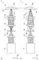
図1は、本発明の第1の実施形態に係るレーザ加工装置の構成を示す図である。図1(a)はレーザ加工装置1の正面図であり、図1(b)はレーザ加工装置1の側面図である。なお、図1(a)及び(b)にはレーザ加工装置1と共に加工対象物Wが示されている。 FIG. 1 is a diagram showing a configuration of a laser processing apparatus according to the first embodiment of the present invention. FIG. 1A is a front view of the laser processing apparatus 1, and FIG. 1B is a side view of the laser processing apparatus 1. 1A and 1B show the workpiece W together with the laser processing apparatus 1.
レーザ加工装置1は、光源10と、光源10から出射されるレーザ光の光軸方向Zに略垂直に順に配置された集光レンズ20と、アパーチャ板(アパーチャ手段)30と、コリメートレンズ40と、第1及び第2のシリンドリカルレンズ(集光手段)51,52とを備えている。 The laser processing apparatus 1 includes a
光源10は、例えば半導体レーザを有しており、レーザ光を集光レンズ20へ向けて出射する。 The
集光レンズ20は、光源10からのレーザ光を集光して、アパーチャ板30へ出力する。 The condensing
アパーチャ板30は平板状を成しており、アパーチャ板30の中央部には、集光レンズ20からのレーザ光を通過させるための孔(開口)30aが形成されている。アパーチャ板30の材料には、後述するように、加工対象物Wからの反射光を遮るために反射率が高く、且つ、この反射光による温度上昇を抑制するために熱伝導率が高い銅やアルミニウムなどの金属が用いられることが好ましい。更に、アパーチャ板30には、加工対象物Wからの反射光の反射を高めるために金メッキなどの表面処理が施されることが好ましい。また、アパーチャ板30の材料には、反射率が高く且つ耐熱性に優れたセラミックが用いられてもよい。 The
これらの集光レンズ20とアパーチャ板30とは、アパーチャ板30の孔30aにおいて集光レンズ20の焦点が生じるように配置されている。アパーチャ板30の孔30aを通過したレーザ光は、コリメートレンズ40に入射する。 The
コリメートレンズ40は、入射したレーザ光を平行光に変換して、第1のシリンドリカルレンズ51へ出力する。 The collimating
第1のシリンドリカルレンズ(第1の光学素子、第1の集光レンズ)51は、光軸方向Zに略直交する第1の方向Xに円柱状の屈折率分布を有しており、第1の方向Xの一方向のみに集光作用を有している。すなわち、第1のシリンドリカルレンズ51は、第1の方向Xに分布するレーザ光を集光するが、光軸方向Z及び第1の方向Xに略直交する第2の方向Yに分布するレーザ光を集光しない。このようにして、第1のシリンドリカルレンズ51は、第1の方向Xに分布するレーザ光が集光してなる第1の焦線51aを有することとなる。第1の焦線51aは、光軸方向Zにおいて加工対象物Wの加工面Waより手前(レーザ加工装置1側)に位置する。第1のシリンドリカルレンズ51は、集光したレーザ光を第2のシリンドリカルレンズ52へ出力する。 The first cylindrical lens (first optical element, first condensing lens) 51 has a columnar refractive index distribution in a first direction X substantially orthogonal to the optical axis direction Z. It has a light condensing effect only in one direction X. That is, the first
第2のシリンドリカルレンズ52(第2の光学素子、第2の集光レンズ)は、第1のシリンドリカルレンズ51と離間して配置されている。第2のシリンドリカルレンズ52は、第2の方向Yに円柱状の屈折率分布を有しており、第2の方向Yの一方向のみに集光作用を有している。すなわち、第2のシリンドリカルレンズ52は、第2の方向Yに分布するレーザ光を集光するが、第1の方向Xに分布するレーザ光を集光しない。このようにして、第2のシリンドリカルレンズ52は、第2の方向Yに分布するレーザ光が集光してなる第2の焦線52aを有することとなる。第2の焦線52aは、光軸方向Zにおいて加工対象物Wの加工面Waより後方(レーザ加工装置1と反対側)に位置する。第2のシリンドリカルレンズ52は、集光したレーザ光を加工対象物Wの加工面Waに対して略垂直に出力する。 The second cylindrical lens 52 (second optical element, second condensing lens) is disposed away from the first
このように、第1及び第2のシリンドリカルレンズ51,52は、集光手段として機能して、レーザ光に非点収差を付加する。非点収差によって生じる第1の焦線51aと第2の焦線52aとの位置は、光軸方向Zにおいて異なる。そして、加工対象物Wの加工面Waは、光軸方向Zにおいて第1の焦線51aと第2の焦線52aとによって挟まれる位置に設定される。 Thus, the 1st and 2nd
このような構成により、図1(a)及び(b)に示すように、加工対象物Wの加工面Waからの反射光は、アパーチャ板30において孔30aの径より大きいビーム径を有することとなる。その結果、加工対象物Wの加工面Waからの反射光の一部はアパーチャ板30によって遮られ、孔30aを通過して光源10へ戻る戻り光が低減される。なお、第1及び第2の焦線51a,52aを加工対象物Wの加工面Waから離すほど、より大きな戻り光の低減効果が得られる。 With such a configuration, as shown in FIGS. 1A and 1B, the reflected light from the processing surface Wa of the workpiece W has a beam diameter larger than the diameter of the
ところで、実使用環境下では、レーザ加工装置1と加工対象物Wとの位置関係が変化することがあり、例えば、レーザ加工装置1の設置時や調整時、加工対象物Wの入れ替え時などに、光軸方向Zにおける加工対象物Wの加工面Waの位置と第1の焦線51aの位置とが一致してしまうことがある。すると、加工対象物Wからの反射光における第1の方向Xのビーム径が、アパーチャ板30において孔30aの径まで集光してしまう。ところが、第2の焦線52aが加工対象物Wの加工面Waの位置と異なる位置に生じるので、加工対象物Wからの反射光における第2の方向Yのビーム径が、アパーチャ板30において孔30aの径より大きい。 By the way, in an actual use environment, the positional relationship between the laser processing apparatus 1 and the workpiece W may change. For example, when the laser processing apparatus 1 is installed or adjusted, or when the workpiece W is replaced. The position of the processing surface Wa of the workpiece W in the optical axis direction Z may coincide with the position of the first
同様に、光軸方向Zにおける加工対象物Wの加工面Waの位置と第2の焦線52aの位置とが一致して、加工対象物Wからの反射光における第2の方向Yのビーム径が、アパーチャ板30において孔30aの径まで集光しても、第1の焦線51aが加工対象物Wの加工面Waの位置と異なる位置に生じるので、加工対象物Wからの反射光における第1の方向Xのビーム径が、アパーチャ板30において孔30aの径より大きい。 Similarly, the position of the processing surface Wa of the processing object W in the optical axis direction Z coincides with the position of the second
したがって、第1の実施形態のレーザ加工装置1によれば、加工対象物Wとの位置関係に依存することなく、アパーチャ板30が加工対象物Wからの反射光の一部を遮ることとなり、孔30aを通過して光源10へ戻る戻り光を低減することができる。 Therefore, according to the laser processing apparatus 1 of the first embodiment, the
また、第1の実施形態のレーザ加工装置1によれば、加工対象物Wの加工面Waが、光軸方向Zにおいて第1の焦線51aと第2の焦線52aとによって挟まれる位置に設定されるので、例えば、加工対象物Wの加工面Waが光軸方向Zにおいて第1及び第2の焦線51a,52aの一方側にずれると、加工対象物Wの加工面Waと第1及び第2の焦線51a,52aの他方との距離がより離れることとなる。したがって、アパーチャ板30において、加工対象物Wからの反射光における第1及び第2の方向X,Yの一方のビーム径が小さくなる場合には、第1及び第2の方向X,Yの他方のビーム径が大きくなることとなる。故に、加工対象物Wとの位置関係に対する光源10への戻り光の低減効果のばらつきを低減することができる。 Further, according to the laser processing apparatus 1 of the first embodiment, the processing surface Wa of the processing target W is located at a position sandwiched between the first
ところで、上記した特許文献1に記載のレーザ加工装置では、反射光を戻らないように周囲に放出しているので危険である。しかしながら、第1の実施形態のレーザ加工装置1では、反射光をレーザ加工装置1内に戻して内部において光源10に戻らないように構成されているので、周囲に放出されることがなく安全である。 By the way, in the laser processing apparatus described in Patent Document 1, the reflected light is emitted to the surroundings so as not to return, which is dangerous. However, the laser processing apparatus 1 according to the first embodiment is configured so that the reflected light is returned into the laser processing apparatus 1 and is not returned to the
また、他の特許文献(特開昭63−63589号公報)には、加工対象物からの反射光を検出し、レーザ光出力を制御するレーザ加工装置が記載されている。このレーザ加工装置によれば、加工対象物からの反射光が大きい場合にレーザ光出力を小さくすることができ、その結果、光源の半導体レーザに戻る反射光の強度を弱めることができる。しかしながら、このレーザ加工装置では、加工対象物からの反射光の強度変化によって、レーザ光出力が変化してしまうので、均一なレーザ加工が困難である。一方、第1の実施形態のレーザ加工装置1によれば、レーザ光の強度を変化させることなく光源10への戻り光を低減できるので、均一なレーザ加工が可能である。 Another patent document (Japanese Patent Laid-Open No. 63-63589) describes a laser processing apparatus that detects reflected light from an object to be processed and controls the laser light output. According to this laser processing apparatus, when the reflected light from the workpiece is large, the laser light output can be reduced, and as a result, the intensity of the reflected light returning to the semiconductor laser of the light source can be weakened. However, in this laser processing apparatus, the laser light output changes due to the intensity change of the reflected light from the object to be processed, so that uniform laser processing is difficult. On the other hand, according to the laser processing apparatus 1 of the first embodiment, since the return light to the
また、第1の実施形態のレーザ加工装置1によれば、光軸方向Zにおける第1及び第2の焦線51a,52aと加工対象物Wの加工面Waとの位置関係を変更することによって、すなわち、光軸方向Zにおける第1及び第2のシリンドリカルレンズ51,52と加工対象物Wとの位置関係を変更することによって、レーザ光のビーム形状を容易に楕円とすることができると共に、レーザ光の長手方向及び短手方向を容易に変更することができる。 Further, according to the laser processing apparatus 1 of the first embodiment, by changing the positional relationship between the first and second
このように、レーザ光のビーム形状を楕円にすると、加工対象物Wに対するレーザ光の走査方向を変更することによって、様々な加工に適したレーザ加工装置を実現することができる。 As described above, when the beam shape of the laser beam is an ellipse, a laser processing apparatus suitable for various types of processing can be realized by changing the scanning direction of the laser beam with respect to the workpiece W.
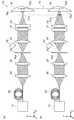
例えば、図2に示すように、加工対象物Wに対してレーザ光を長手方向S1に走査すると、単位面積及び単位時間あたりのレーザ光強度を増加することができ、切断や溶接などの単位面積及び単位時間あたりに大きなパワーを要する加工に適したレーザ加工装置を実現することができる。 For example, as shown in FIG. 2, when the workpiece W is scanned with laser light in the longitudinal direction S1, the laser light intensity per unit area and unit time can be increased, and unit areas such as cutting and welding can be increased. In addition, a laser processing apparatus suitable for processing that requires a large power per unit time can be realized.
一方、図3に示すように、加工対象物Wに対してレーザ光を短手方向S2に走査すると、単位時間あたりのレーザ光照射面積を増加することができ、表面処理などの単位時間あたりの処理面積を要する加工に適したレーザ加工装置を実現することができる。 On the other hand, as shown in FIG. 3, when the workpiece W is scanned with the laser light in the short direction S2, the laser light irradiation area per unit time can be increased, and the surface treatment or other unit time can be increased. A laser processing apparatus suitable for processing requiring a processing area can be realized.
ここで、第1の焦線51aを含むZY平面上の幾何光学的焦点距離fzyと、第2の焦線52aを含むZX平面上の幾何光学的焦点距離fzxとから、平均焦点距離fave=(fzy+fzx)/2を求め、集光レンズ系に入るビーム径をdとした場合のFナンバーをF=fave/dとすると、実用上好ましい非点隔差|fzy−fzx|の範囲は、0.01F<|fzy−fzx|/d<0.2Fであると考えられる。
[第2の実施形態]Here, from the geometric optical focal length fzy on the ZY plane including the first
[Second Embodiment]
図4は、本発明の第2の実施形態に係るレーザ加工装置の構成を示す図である。図4(a)はレーザ加工装置1Aの正面図であり、図4(b)はレーザ加工装置1Aの側面図である。なお、図4(a)及び(b)にはレーザ加工装置1Aと共に加工対象物Wが示されている。 FIG. 4 is a diagram showing a configuration of a laser processing apparatus according to the second embodiment of the present invention. 4A is a front view of the
レーザ加工装置1Aは、レーザ加工装置1において光ファイバ(導光手段)60と、コリメートレンズ65と、冷却器70を更に備えている構成で第1の実施形態と異なっている。レーザ加工装置1Aの他の構成は、レーザ加工装置1と同一である。 1 A of laser processing apparatuses differ from 1st Embodiment by the structure further provided with the optical fiber (light guide means) 60, the collimating
光ファイバ60の一端は光源10に接続されており、他端は光軸方向に向けて配置されている。光ファイバ60は、光源10からのレーザ光を一端から他端へ導き、コリメートレンズ65へ出力する。 One end of the
コリメートレンズ65は、入射したレーザ光を平行光に変換して、集光レンズ20へ出力する。 The collimating
冷却器70は、アパーチャ板30を冷却するために設けられている。冷却器70には、空冷用ファンや水冷用ヒートシンクなどが用いられる。 The cooler 70 is provided to cool the
この第2の実施形態のレーザ加工装置1Aでも、第1の実施形態のレーザ加工装置1と同様の利点を得ることができる。 In the
ここで、レーザ加工装置1Aのようなファイバ導光型高出力半導体レーザが用いられる場合、戻り光によって、半導体レーザだけでなく、光ファイバの出力端部が過熱されて焼損する虞がある。しかしながら、第2の実施形態のレーザ加工装置1Aによれば、アパーチャ板30が戻り光を低減するので、光ファイバの出力端部の過熱及び焼損をも低減することができる。 Here, when a fiber light guide type high output semiconductor laser such as the
また、アパーチャ板30は加工対象物Wからの反射光の一部を遮るので、アパーチャ板30の温度が上昇し、その結果、アパーチャ板30では急速に酸化が進むことがある。酸化が進むと反射率が下がり、より多くの戻り光を吸収するようになる。しかしながら、第2の実施形態のレーザ加工装置1Aによれば、冷却器70を備えているので、アパーチャ板30の温度上昇を抑制することができ、その結果、アパーチャ板30の劣化を抑制することができる。
[第3の実施形態]In addition, since the
[Third Embodiment]
図5は、本発明の第3の実施形態に係るレーザ加工装置の構成を示す図である。図5(a)はレーザ加工装置1Bの正面図であり、図5(b)はレーザ加工装置1Bの側面図である。なお、図5(a)及び(b)にはレーザ加工装置1Bと共に加工対象物Wが示されている。 FIG. 5 is a diagram showing a configuration of a laser processing apparatus according to the third embodiment of the present invention. FIG. 5A is a front view of the
レーザ加工装置1Bは、レーザ加工装置1Aにおいて集光レンズ20、コリメートレンズ65及び冷却器70を備えていない点で第2の実施形態と異なっている。そのため、光ファイバ60の他端は、レーザ光をアパーチャ板30の孔30aに向けて出射するように配置されている。レーザ加工装置1Bの他の構成は、レーザ加工装置1Aと同一である。 The
この第3の実施形態のレーザ加工装置1Bでも、第2の実施形態のレーザ加工装置1Aと同様の利点を得ることができる。
[第4の実施形態]The
[Fourth Embodiment]
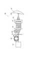
図6は、本発明の第4の実施形態に係るレーザ加工装置の構成を示す図である。図6(a)はレーザ加工装置1Cの正面図であり、図6(b)はレーザ加工装置1Cの側面図である。なお、図6(a)及び(b)にはレーザ加工装置1と共に加工対象物Wが示されている。 FIG. 6 is a diagram showing a configuration of a laser processing apparatus according to the fourth embodiment of the present invention. FIG. 6A is a front view of the
レーザ加工装置1Cは、レーザ加工装置1において第1及び第2のシリンドリカルレンズ51,52に代えて球面レンズ53を備えている構成で第1の実施形態と異なっている。レーザ加工装置1Cの他の構成は、レーザ加工装置1と同一である。 The laser processing apparatus 1 </ b> C is different from the first embodiment in that the laser processing apparatus 1 includes a
球面レンズ53は、光軸方向Zに対して垂直な状態から傾いて配置されている。これにより、球面レンズ53は、集光手段として機能して、レーザ光に非点収差を付加する。そして、非点収差によって生じる第1の焦線51aと第2の焦線52aとは、光軸方向Zにおいて加工対象物Wの加工面Waを挟み込む位置に生じる。 The
この第4の実施形態のレーザ加工装置1Cでも、第1の実施形態のレーザ加工装置1と同様の利点を得ることができる。 In the
なお、本発明は上記した本実施形態に限定されることなく種々の変形が可能である。 The present invention is not limited to the above-described embodiment, and various modifications can be made.
本実施形態では、非点収差を付加するための集光手段として2枚のシリンドリカルレンズ51,52又は光軸方向Zに対して傾けた球面レンズ53を例示したが、非点収差を付加するための集光手段としては様々な態様が適用可能である。 In the present embodiment, the two
例えば、図1において、第1及び第2のシリンドリカルレンズ51,52に代えて、それぞれ、比較的長い焦点距離のシリンドリカルレンズと、非球面レンズ(第2の光学素子、第2の集光レンズ)とを備えていてもよい。非球面レンズは、第1の方向X及び第2の方向Yを含む平面に対して等方的な屈折率分布を有しており、等方的な集光作用を有している。すなわち、非球面レンズは、光軸Zを中心とする同心円状に入射した光を1点に集光するように作用する。このようにして、シリンドリカルレンズは、第1の方向Xに分布するレーザ光が集光してなる第1の焦線51aを有することとなり、シリンドリカルレンズと非球面レンズとは、第2の方向Yに分布するレーザ光が集光してなる第2の焦線52aを生じさせることとなる。このように、比較的長い焦点距離のシリンドリカルレンズと非球面レンズとを組み合わせると、強い球面収差を発生させずに非点隔差を与えることができる。なお、非球面レンズに代えてアプラナートレンズやアクロマートレンズなどが用いられても同様の利点が得られる。 For example, in FIG. 1, instead of the first and second
また、以下に示すように、非点収差を付加するための集光手段を一枚の多焦点レンズで実現してもよい。図7は、非点収差を付加するための多焦点レンズの一例を示す図である。図7(a)は多焦点レンズ54の側面図を示しており、図7(b)は図7(a)に対して90度回転した方向から見た多焦点レンズ54の側面図を示している。多焦点レンズ54の一方の面54aと他方の面54bとは、互いに略直交する円柱面をなしている。これにより、多焦点レンズ54は、2枚のシリンドリカルレンズ51,52と同様に、レーザ光に非点収差を付加することができ、本実施形態と同様に、第1及び第2の焦線51a,52aを生じることができる。 Further, as shown below, the light condensing means for adding astigmatism may be realized by a single multifocal lens. FIG. 7 is a diagram illustrating an example of a multifocal lens for adding astigmatism. FIG. 7A shows a side view of the
また、非点収差を付加するための集光手段は、トーリックレンズで実現することも可能である。また、非点収差を付加するための集光手段には、シリンドリカルレンズ(凹又は凸)のように光軸方向Zに略垂直な一方向に集光力をもった光学素子と球面(或いは非球面)レンズとが組み合わされて用いられてもよい。また、非点収差を付加するための集光手段には、フレネルレンズや反射鏡、屈折率分布レンズ、回折光学系などの光軸方向Zに略垂直な一方向に集光力をもった光学素子が光軸方向Zに対して略直交させて用いられてもよいし、これらのフレネルレンズや反射鏡、屈折率分布レンズ、回折光学系などが組み合わされて用いられてもよい。また、非点収差を付加するための集光手段には、回折レンズと屈折レンズを組合せた多焦点レンズが用いられてもよい。 Moreover, the light condensing means for adding astigmatism can be realized by a toric lens. The condensing means for adding astigmatism includes an optical element having a condensing power in one direction substantially perpendicular to the optical axis direction Z, such as a cylindrical lens (concave or convex), and a spherical surface (or non-spherical). (Spherical) lenses may be used in combination. In addition, as a condensing means for adding astigmatism, a light having a condensing power in one direction substantially perpendicular to the optical axis direction Z, such as a Fresnel lens, a reflecting mirror, a refractive index distribution lens, and a diffractive optical system The element may be used so as to be substantially orthogonal to the optical axis direction Z, or a Fresnel lens, a reflecting mirror, a refractive index distribution lens, a diffractive optical system, or the like may be used in combination. In addition, a multifocal lens that is a combination of a diffractive lens and a refractive lens may be used as the condensing means for adding astigmatism.
本実施形態では、加工対象物Wからの反射光の一部を遮るためのアパーチャ手段として孔30aを有するアパーチャ板30を例示したが、光源10における半導体レーザとしてLD(Laser Diode)バーやLDバーをスタックした高出力半導体レーザを用いた場合、アパーチャとしては孔よりスリットであることが好ましく、このスリットの大きさが調整可能であることが好ましい。以下には、その一例を示す。 In the present embodiment, the
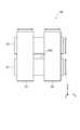
図8は、アパーチャ手段の変形例を示す正面図である。図8に示すアパーチャ手段80は、光軸方向Zに略垂直な第1の方向Xに並置された2枚の平板81,82と、光軸方向Z及び第1の方向Xに略垂直な第2の方向Yに並置された2枚の平板83,84とを有している。これらの平板81,82,83,84に囲まれる領域が、レーザ光を通過させるためのスリット80aを形成している。平板81,82はそれぞれ第1の方向Xに平行移動可能であり、平板83,84はそれぞれ第2の方向Yに平行移動可能である。これによって、スリット80aの大きさが調整可能となっており、スリット80aの大きさをレーザ光の集光ビーム形状に容易に合わせることができる。なお、平板81,82,83,84の材料には、反射率及び熱伝導率が高い銅やアルミニウムなどの金属、反射率が高く且つ耐熱性に優れたセラミックなどが用いられることが好ましい。 FIG. 8 is a front view showing a modification of the aperture means. The aperture means 80 shown in FIG. 8 includes two
また、アパーチャ手段は光軸方向Zに多段に設けられてもよい。これによれば、反射光に起因する発熱を分散させることができる。 The aperture means may be provided in multiple stages in the optical axis direction Z. According to this, the heat generated due to the reflected light can be dispersed.
第3の実施形態では、レーザ加工装置1Bが加工対象物Wの加工面Waに対してレーザ光を略垂直に照射したが、図9に示すように、レーザ加工装置1Bは加工対象物Wの加工面Waに対してレーザ光を斜め方向から照射するとより効果的である。これによれば、アパーチャ板30の孔30aに向けて戻る加工対象物Wからの反射光を低減することができ、光源10への戻り光を低減することができる。集光レンズ系として非点収差を有さない集光レンズを用いた場合、加工対象物Wの加工面Waに焦点を結ぶと、レーザ光を僅かに傾けただけでは反射光をアパーチャ板30の孔30aからずらすことが困難であるが、本実施形態のように集光レンズ系として非点収差を有する集光レンズを用いると、加工対象物Wの加工面Waに対してレーザ光を僅かに傾けただけで反射光をアパーチャ板30の孔30aからずらすことができる。 In the third embodiment, the
また、レーザ加工装置1Bは、アパーチャ板30の孔30aの周辺における反射光を観測するカメラやセンサを更に有していてもよい。図9では、レーザ加工装置1BがCCDカメラ90を更に備えている。このように、レーザ加工装置1BがCCDカメラ90を備えると、上記したように、加工対象物Wの加工面Waに対してレーザ光を斜め方向から照射する際の角度の調整や確認を容易に行うことができる。 The
同様に、第1及び第2の実施形態でも、レーザ加工装置1,1Aは加工対象物Wの加工面Waに対してレーザ光を斜め方向から照射することが好ましい。また、第1及び第2の実施形態でも、レーザ加工装置1,1Aはアパーチャ板30の孔30aの周辺における反射光を観測するカメラやセンサを更に有していてもよい。 Similarly, also in the first and second embodiments, it is preferable that the
また、本実施形態では、集光レンズ20、アパーチャ板30、コリメートレンズ40,65、第1及び第2のシリンドリカルレンズ51,52が光軸方向Zに略垂直に配置されたが、垂直でなくても交差していればよい。また、第1及び第2のシリンドリカルレンズ51,52は、屈折率分布が互いに略直交するように配置されたが、直交せずとも交差していればよい。すなわち、非点収差によって生じる第1及び第2の焦線51a,52aは、直交せずとも交差していればよい。 In the present embodiment, the condensing
実施例に基づいて、本発明をより具体的に説明する。
[実施例1]Based on an Example, this invention is demonstrated more concretely.
[Example 1]
実施例1のレーザ加工装置は、第1の実施形態のレーザ加工装置1に基づいて以下の通り構成した。 The laser processing apparatus of Example 1 was configured as follows based on the laser processing apparatus 1 of the first embodiment.
光源10における高出力半導体レーザには、波長約980nmのLDバーをスタックしたものが用いられた。各LDバーは長さ1cmで、ファーストアクシスコリメートレンズとスローアクシスコリメートレンズとが装着された。このLDバーが約2mm間隔で5段積み重ねられて、LDスタックが生成された。ビーム広がり角は、ファーストアクシスが約1度であり、スローアクシスが約3度であった。LDバーは冷却されており、5段スタックの実用上の最大レーザ出力は約250Wである。 As the high-power semiconductor laser in the
集光レンズ20には、直径30mm、有効焦点距離26mmのガラス製非球面レンズが用いられた。 As the
アパーチャ板30には、縦横50mm、厚さ1mmの純銅板に金メッキを施したものが使用された。孔30aの大きさとしては、縦(ファーストアクシス)が約0.5mmであり、横が約1.5mmである。アパーチャ板30は、手動ステージを用いて、集光レンズ20の焦点位置に配置した。 As the
コリメートレンズ40には、集光レンズ20と同じく直径30mm、有効焦点距離26mmのガラス製非球面レンズが用いられた。コリメートレンズ40を通過したレーザ光は、光源10における高出力半導体レーザと同程度にコリメートされた。 As the
第1のシリンドリカルレンズ51には、縦横30mm、有効焦点距離60mmのガラス製レンズが用いられた。また、第2のシリンドリカルレンズ52には、縦横30mm、有効焦点距離50mmのガラス製レンズが用いられた。第1のシリンドリカルレンズ51の第1の焦線51aと第2のシリンドリカルレンズ52の第2の焦線52aとの間隔は約4mmとした。 As the first
加工対象物Wには、厚さ2mmのステンレス板を用いた。ステンレス板は、第1の焦線51aと第2の焦線52aとのほぼ中間に、光軸方向Zに対して略垂直に配置した。 A stainless steel plate having a thickness of 2 mm was used as the workpiece W. The stainless steel plate was disposed substantially perpendicular to the optical axis direction Z in the middle between the first
レーザ加工中にCCDカメラで観察したところ、アパーチャ板30の孔30aの周辺部に強い戻り光が観測された。加工対象物Wからの戻り光がそのままLDスタックに戻ると、通常、ファーストアクシスコリメートレンズやスローアクシスコリメートレンズ、そしてその周辺部が、戻り光が無い(加工対象物Wを配置しない)場合に比べて明らかに温度上昇するのに対して、実施例1では、それらの部位の温度は加工対象物Wの有無に関係なく約65度(レーザ出力250W時)であった。なお、この測定結果は熱画像センサによるものである。 When observed with a CCD camera during laser processing, strong return light was observed around the
これまでの経験から、LD素子直近のコリメートレンズ(ファーストアクシス、スローアクシス)やその周辺に戻り光による温度上昇が観られると、LD素子自体の寿命が低下することが判っている。本実施例では、LD直近のコリメートレンズやその周辺に、戻り光による温度上昇は観られないため、戻り光による高出力半導体レーザの寿命の減少が防止できると考えられる。
[実施例2]From experience so far, it has been found that if the temperature rise due to the return light is observed in the collimating lens (first axis, slow axis) in the immediate vicinity of the LD element or the periphery thereof, the lifetime of the LD element itself is reduced. In this example, since no temperature rise due to the return light is observed in the collimating lens immediately adjacent to the LD or the periphery thereof, it is considered that the reduction in the lifetime of the high-power semiconductor laser due to the return light can be prevented.
[Example 2]
実施例2のレーザ加工装置は、第2の実施形態のレーザ加工装置1Aに基づいて以下の通り構成した。 The laser processing apparatus of Example 2 was configured as follows based on the
光源10及び光ファイバ60には、ファイバ導光型高出力半導体レーザが用いられた。高出力半導体レーザの波長は約980nmである。光ファイバ60のコア径は600μmであり、NAは0.2である。LD素子は水冷されており、実用上の最大レーザ出力は約500Wである。 For the
コリメートレンズ65には、直径100mm、有効焦点距離100mmのガラス製非球面レンズが用いられた。集光レンズ20及びコリメートレンズ40には、直径50mm、有効焦点距離40mmのガラス製非球面レンズが用いられた。 As the
アパーチャ板30には、直径50mm、厚さ1mmの純銅板に金メッキを施したものが用いられた。孔30aの大きさは直径約300μmである。なお、アパーチャ板30は、集光レンズ20の焦点位置に配置した。 As the
第1のシリンドリカルレンズ51には、90mm×100mm、有効焦点距離200mmのガラス製レンズが用いられた。また、第2のシリンドリカルレンズ52には、90mm×100mm、有効焦点距離150mmのガラス製レンズが用いられた。第1のシリンドリカルレンズ51の第1の焦線51aと第2のシリンドリカルレンズ52の第2の焦線52aとの間隔は約8mmとした。 As the first
加工対象物Wには、厚さ5mmのステンレス板を用いた。ステンレス板は、第1の焦線51aと第2の焦線52aとのほぼ中間に、光軸方向Zに対して略垂直に配置した。 As the workpiece W, a stainless steel plate having a thickness of 5 mm was used. The stainless steel plate was disposed substantially perpendicular to the optical axis direction Z in the middle between the first
レーザ加工中にCCDカメラで観察したところ、アパーチャ板30の孔30aの周辺部に強い戻り光が観測されたが、光ファイバ出口端付近の温度は、加工対象物Wの有無に関係なく約40度(500W時)であった。このことから、実施例2では、戻り光による導光用ファイバの焼損防止に効果があるものと考えられる。 When observed with a CCD camera during laser processing, strong return light was observed around the
1,1A,1B,1C…レーザ加工装置、10…光源、20…集光レンズ、30…アパーチャ板(アパーチャ手段)、30a…孔(開口)、40,65…コリメートレンズ、51,52…第1及び第2のシリンドリカルレンズ(集光手段、第1及び第2の光学素子、第1及び第2の集光レンズ)、51a,52a…第1及び第2の焦線、53…球面レンズ、54…多焦点レンズ、60…光ファイバ、70…冷却器(冷却手段)、W…加工対象物、Wa…加工面、X,Y…第1及び第2の方向、Z…光軸方向。 DESCRIPTION OF
Claims (10)
Translated fromJapanese平板状をなすと共に前記光源からのレーザ光の光軸方向に交差して配置されており、前記光源からのレーザ光を通過させるための開口を有するアパーチャ手段と、
前記アパーチャ手段に対して前記光源と反対側に配置されており、前記アパーチャ手段の前記開口を通過したレーザ光を集光して加工対象物に照射する集光手段と、
を備え、
前記集光手段は、前記アパーチャ手段の前記開口を通過したレーザ光に非点収差を付加し、
前記非点収差によって生じる前記集光手段の第1の焦線と第2の焦線とであって、前記光軸方向に交差する第1の方向に分布するレーザ光が集光してなる当該第1の焦線と、前記光軸方向及び前記第1の方向に交差する第2の方向に分布するレーザ光が集光してなる当該第2の焦線との位置は、前記光軸方向において異なる、
ことを特徴とする、レーザ加工装置。A light source that emits laser light;
Aperture means having a flat plate shape and disposed so as to intersect the optical axis direction of the laser light from the light source, and having an opening for allowing the laser light from the light source to pass through,
A condensing unit that is disposed on the opposite side of the light source with respect to the aperture unit, condenses the laser light that has passed through the opening of the aperture unit, and irradiates a workpiece;
With
The condensing means adds astigmatism to the laser light that has passed through the aperture of the aperture means,
The first focal line and the second focal line of the condensing means caused by the astigmatism, the laser light distributed in a first direction intersecting the optical axis direction being condensed The position of the first focal line and the second focal line obtained by condensing the laser beam distributed in the second direction intersecting the optical axis direction and the first direction is the optical axis direction. Different in
The laser processing apparatus characterized by the above-mentioned.
前記第1の方向の一方向に集光作用を有する第1の光学素子と、
前記第2の方向の一方向に集光作用を有する第2の光学素子と、
を有する、請求項1〜4の何れか1項に記載のレーザ加工装置。The light collecting means includes
A first optical element having a light collecting action in one direction of the first direction;
A second optical element having a condensing function in one direction of the second direction;
The laser processing apparatus of any one of Claims 1-4 which has these.
前記第1の方向の一方向に集光作用を有する第1の光学素子と、
前記第1の方向及び前記第2の方向を含む平面に対して等方的な集光作用を有する第2の光学素子と、
を有する、請求項1〜4の何れか1項に記載のレーザ加工装置。The light collecting means includes
A first optical element having a light collecting action in one direction of the first direction;
A second optical element having an isotropic condensing action with respect to a plane including the first direction and the second direction;
The laser processing apparatus of any one of Claims 1-4 which has these.
前記光軸方向に交差して配置されており、前記第1の方向に円柱状の屈折率分布を有することによって前記第1の焦線を生じさせる第1の集光レンズと、
前記光軸方向に交差して配置されると共に前記光軸方向に前記第1の集光レンズと離間して配置されており、前記第2の方向に円柱状の屈折率分布を有することによって前記第2の焦線を生じさせる第2の集光レンズと、
をそれぞれ前記第1の光学素子と前記第2の光学素子として有する、請求項5に記載のレーザ加工装置。The light collecting means includes
A first condensing lens that is arranged so as to intersect the optical axis direction and that generates a first focal line by having a cylindrical refractive index distribution in the first direction;
By being disposed so as to intersect the optical axis direction and spaced apart from the first condenser lens in the optical axis direction, and having a cylindrical refractive index distribution in the second direction, A second condenser lens that produces a second focal line;
The laser processing apparatus according to claim 5, wherein the first optical element and the second optical element are respectively included.
前記光軸方向に交差して配置されており、前記第1の方向に円柱状の屈折率分布を有することによって前記第1の焦線を生じさせる第1の集光レンズと、
前記光軸方向に交差して配置されると共に前記光軸方向に前記第1の集光レンズと離間して配置されており、前記第1の方向及び前記第2の方向を含む平面に対して等方的な屈折率分布を有する第2の集光レンズと、
をそれぞれ前記第1の光学素子と前記第2の光学素子として有し、
前記集光手段は、前記第1の集光レンズと前記第2の集光レンズとの集光作用によって前記第2の焦線を生じさせる、
請求項6に記載のレーザ加工装置。The light collecting means includes
A first condensing lens that is arranged so as to intersect the optical axis direction and that generates a first focal line by having a cylindrical refractive index distribution in the first direction;
It is arranged so as to intersect the optical axis direction and is spaced apart from the first condenser lens in the optical axis direction, and with respect to a plane including the first direction and the second direction. A second condenser lens having an isotropic refractive index distribution;
Respectively as the first optical element and the second optical element,
The condensing means generates the second focal line by the condensing action of the first condensing lens and the second condensing lens;
The laser processing apparatus according to claim 6.
Priority Applications (3)
| Application Number | Priority Date | Filing Date | Title |
|---|---|---|---|
| JP2007241251AJP2009072789A (en) | 2007-09-18 | 2007-09-18 | Laser machining apparatus |
| DE102008045778ADE102008045778A1 (en) | 2007-09-18 | 2008-09-04 | laser system |
| US12/212,010US20090071947A1 (en) | 2007-09-18 | 2008-09-17 | Laser beam machine |
Applications Claiming Priority (1)
| Application Number | Priority Date | Filing Date | Title |
|---|---|---|---|
| JP2007241251AJP2009072789A (en) | 2007-09-18 | 2007-09-18 | Laser machining apparatus |
Publications (1)
| Publication Number | Publication Date |
|---|---|
| JP2009072789Atrue JP2009072789A (en) | 2009-04-09 |
Family
ID=40348793
Family Applications (1)
| Application Number | Title | Priority Date | Filing Date |
|---|---|---|---|
| JP2007241251APendingJP2009072789A (en) | 2007-09-18 | 2007-09-18 | Laser machining apparatus |
Country Status (3)
| Country | Link |
|---|---|
| US (1) | US20090071947A1 (en) |
| JP (1) | JP2009072789A (en) |
| DE (1) | DE102008045778A1 (en) |
Cited By (8)
| Publication number | Priority date | Publication date | Assignee | Title |
|---|---|---|---|---|
| JP2012135808A (en)* | 2010-12-27 | 2012-07-19 | Omron Corp | Laser beam machining apparatus and laser beam machining method |
| JP2012135807A (en)* | 2010-12-27 | 2012-07-19 | Omron Corp | Laser beam machining apparatus and laser beam machining method |
| JP2016518698A (en)* | 2013-03-12 | 2016-06-23 | アプライド マテリアルズ インコーポレイテッドApplied Materials,Incorporated | Customized pupil stop shape for controlling edge profiles in laser annealing systems |
| JPWO2014126137A1 (en)* | 2013-02-13 | 2017-02-02 | 住友化学株式会社 | Laser light irradiation apparatus and optical member bonding body manufacturing apparatus |
| JPWO2016135906A1 (en)* | 2015-02-25 | 2017-04-27 | 技術研究組合次世代3D積層造形技術総合開発機構 | Optical processing head, optical processing apparatus and optical processing method |
| JP2017512900A (en)* | 2014-04-02 | 2017-05-25 | ア−カム アーベー | How to fuse workpieces |
| JP2021163914A (en)* | 2020-04-02 | 2021-10-11 | 浜松ホトニクス株式会社 | Laser processing device, laser processing method and wafer |
| JP2021533345A (en)* | 2018-07-30 | 2021-12-02 | イオンキュー インコーポレイテッド | Elliptical beam design using cylindrical optical system |
Families Citing this family (11)
| Publication number | Priority date | Publication date | Assignee | Title |
|---|---|---|---|---|
| DE102010029089B4 (en)* | 2010-05-18 | 2019-08-29 | Carl Zeiss Ag | Optical system for calibrating a light source |
| KR101547806B1 (en)* | 2013-07-29 | 2015-08-27 | 에이피시스템 주식회사 | Device for processing brittle substrate using aspherical lens having multi focus |
| US10357848B2 (en) | 2015-01-19 | 2019-07-23 | General Electric Company | Laser machining systems and methods |
| DE102016111932B4 (en)* | 2016-06-29 | 2018-02-08 | Trumpf Laser Gmbh | Frequency conversion unit and frequency conversion method |
| CN108326423B (en)* | 2018-03-19 | 2020-02-04 | 深圳市恩兴实业有限公司 | Laser welding process |
| CN108489902B (en)* | 2018-05-17 | 2020-09-25 | 电子科技大学 | High-repeatability optical fiber laser micro-flow detector and detection method |
| DE102018127262A1 (en)* | 2018-10-31 | 2020-04-30 | MAX-PLANCK-Gesellschaft zur Förderung der Wissenschaften e.V. | Coating device and method for coating a substrate |
| US12042881B2 (en) | 2018-12-14 | 2024-07-23 | Rtx Corporation | System and method for laser drilling of shaped cooling holes |
| US11707805B2 (en)* | 2018-12-14 | 2023-07-25 | Raytheon Technologies Corporation | System and method for laser drilling of shaped cooling holes |
| JP7303053B2 (en)* | 2019-07-17 | 2023-07-04 | ファナック株式会社 | Adjustment aid and laser welding equipment |
| CN113399825B (en)* | 2020-03-17 | 2022-05-20 | 深圳市联赢激光股份有限公司 | Laser device |
Citations (6)
| Publication number | Priority date | Publication date | Assignee | Title |
|---|---|---|---|---|
| JPH02284785A (en)* | 1989-04-27 | 1990-11-22 | Yamazaki Mazak Corp | Reflected beam absorbing device for laser processing machine |
| JPH04167989A (en)* | 1990-10-31 | 1992-06-16 | Kobe Steel Ltd | Two beam laser welding method |
| JP2005340788A (en)* | 2004-04-28 | 2005-12-08 | Semiconductor Energy Lab Co Ltd | Laser irradiation method and semiconductor device manufacturing method using the same |
| JP2006514886A (en)* | 2003-02-19 | 2006-05-18 | ジェイピー・サーセル・アソシエイツ・インコーポレーテッド | Cutting apparatus and method using variable astigmatic beam spot |
| JP2006224184A (en)* | 2005-02-21 | 2006-08-31 | Toyota Motor Corp | Butt laser welding method and butt laser welding apparatus |
| JP2007167918A (en)* | 2005-12-22 | 2007-07-05 | Hamamatsu Photonics Kk | Laser processing equipment |
Family Cites Families (8)
| Publication number | Priority date | Publication date | Assignee | Title |
|---|---|---|---|---|
| US4498766A (en)* | 1982-03-25 | 1985-02-12 | Becton, Dickinson And Company | Light beam focal spot elongation in flow cytometry devices |
| US4707217A (en)* | 1986-05-28 | 1987-11-17 | The United States Of America As Represented By The Secretary Of The Navy | Single crystal thin films |
| JPS62289387A (en) | 1986-06-06 | 1987-12-16 | Sanoyasu:Kk | Processing method for high-reflection material using carbon dioxide laser |
| JPH0755388B2 (en) | 1986-09-02 | 1995-06-14 | 株式会社小松製作所 | Laser processing method for high reflectance materials |
| ATE176416T1 (en)* | 1990-11-21 | 1999-02-15 | Canon Kk | LASER PROCESSING DEVICE |
| JP3293136B2 (en)* | 1993-06-04 | 2002-06-17 | セイコーエプソン株式会社 | Laser processing apparatus and laser processing method |
| US5838496A (en)* | 1995-08-28 | 1998-11-17 | Asahi Kogaku Kogyo Kabushiki Kaisha | Diffractive multi-focal objective lens |
| US7027155B2 (en)* | 2001-03-29 | 2006-04-11 | Gsi Lumonics Corporation | Methods and systems for precisely relatively positioning a waist of a pulsed laser beam and method and system for controlling energy delivered to a target structure |
- 2007
- 2007-09-18JPJP2007241251Apatent/JP2009072789A/enactivePending
- 2008
- 2008-09-04DEDE102008045778Apatent/DE102008045778A1/ennot_activeWithdrawn
- 2008-09-17USUS12/212,010patent/US20090071947A1/ennot_activeAbandoned
Patent Citations (6)
| Publication number | Priority date | Publication date | Assignee | Title |
|---|---|---|---|---|
| JPH02284785A (en)* | 1989-04-27 | 1990-11-22 | Yamazaki Mazak Corp | Reflected beam absorbing device for laser processing machine |
| JPH04167989A (en)* | 1990-10-31 | 1992-06-16 | Kobe Steel Ltd | Two beam laser welding method |
| JP2006514886A (en)* | 2003-02-19 | 2006-05-18 | ジェイピー・サーセル・アソシエイツ・インコーポレーテッド | Cutting apparatus and method using variable astigmatic beam spot |
| JP2005340788A (en)* | 2004-04-28 | 2005-12-08 | Semiconductor Energy Lab Co Ltd | Laser irradiation method and semiconductor device manufacturing method using the same |
| JP2006224184A (en)* | 2005-02-21 | 2006-08-31 | Toyota Motor Corp | Butt laser welding method and butt laser welding apparatus |
| JP2007167918A (en)* | 2005-12-22 | 2007-07-05 | Hamamatsu Photonics Kk | Laser processing equipment |
Cited By (13)
| Publication number | Priority date | Publication date | Assignee | Title |
|---|---|---|---|---|
| JP2012135808A (en)* | 2010-12-27 | 2012-07-19 | Omron Corp | Laser beam machining apparatus and laser beam machining method |
| JP2012135807A (en)* | 2010-12-27 | 2012-07-19 | Omron Corp | Laser beam machining apparatus and laser beam machining method |
| JPWO2014126137A1 (en)* | 2013-02-13 | 2017-02-02 | 住友化学株式会社 | Laser light irradiation apparatus and optical member bonding body manufacturing apparatus |
| JP2016518698A (en)* | 2013-03-12 | 2016-06-23 | アプライド マテリアルズ インコーポレイテッドApplied Materials,Incorporated | Customized pupil stop shape for controlling edge profiles in laser annealing systems |
| US10444522B2 (en) | 2013-03-12 | 2019-10-15 | Applied Materials, Inc. | Customized pupil stop shape for control of edge profile in laser annealing systems |
| JP2017512900A (en)* | 2014-04-02 | 2017-05-25 | ア−カム アーベー | How to fuse workpieces |
| US10369661B2 (en) | 2015-02-25 | 2019-08-06 | Technology Research Association For Future Additive Manufacturing | Optical processing head, optical machining apparatus, and optical processing method |
| JPWO2016135906A1 (en)* | 2015-02-25 | 2017-04-27 | 技術研究組合次世代3D積層造形技術総合開発機構 | Optical processing head, optical processing apparatus and optical processing method |
| JP2021533345A (en)* | 2018-07-30 | 2021-12-02 | イオンキュー インコーポレイテッド | Elliptical beam design using cylindrical optical system |
| US11536879B2 (en) | 2018-07-30 | 2022-12-27 | IonQ, Inc. | Elliptical beam design using cylindrical optics |
| JP7274181B2 (en) | 2018-07-30 | 2023-05-16 | イオンキュー インコーポレイテッド | Elliptical beam design using cylindrical optics |
| US12332460B2 (en) | 2018-07-30 | 2025-06-17 | IonQ, Inc. | Elliptical beam design using cylindrical optics |
| JP2021163914A (en)* | 2020-04-02 | 2021-10-11 | 浜松ホトニクス株式会社 | Laser processing device, laser processing method and wafer |
Also Published As
| Publication number | Publication date |
|---|---|
| US20090071947A1 (en) | 2009-03-19 |
| DE102008045778A1 (en) | 2009-03-19 |
Similar Documents
| Publication | Publication Date | Title |
|---|---|---|
| JP2009072789A (en) | Laser machining apparatus | |
| EP2716397B1 (en) | Optical system for laser working device, laser working head with such optical system, laser working device with such head, laser focusing method, and laser working method using such method | |
| JP5832412B2 (en) | Optical system and laser processing apparatus | |
| US20060186098A1 (en) | Method and apparatus for laser processing | |
| US10264660B2 (en) | Beam trap, beam guide device, EUV radiation generating apparatus, and method for absorbing a beam | |
| JP2720811B2 (en) | Laser focusing method and apparatus | |
| US20200189029A1 (en) | Laser processing machine | |
| JP2013503751A (en) | Laser focusing head comprising a ZnS lens having a peripheral thickness of at least 5 mm, and method and laser cutting unit using such a focusing head | |
| JP5965454B2 (en) | Direct diode laser processing apparatus and sheet metal processing method using the same | |
| JP2006330071A (en) | Linear beam generating optical apparatus | |
| JP2006263771A (en) | Laser processing apparatus and laser processing method | |
| JP2009525592A (en) | Apparatus for longitudinal pumping of laser media | |
| JP2006192503A (en) | Laser cutting-off method for thin metallic workpiece using bifocal lens | |
| JP2013130835A (en) | Homogenizer, homogenizer device and illuminating device | |
| US20220234137A1 (en) | Laser processing head having a diaphragm to increase scan field of the laser beam | |
| JPWO2019078092A1 (en) | Laser processing equipment | |
| RU2383416C1 (en) | Device for laser processing of materials | |
| JP7398649B2 (en) | Laser processing equipment and laser processing method | |
| JPWO2018051450A1 (en) | Laser device | |
| CN114007801B (en) | Laser processing machine and laser processing method | |
| WO2016046954A1 (en) | Achromatic lens and laser processing machine | |
| JP7433511B2 (en) | Laser processing machine and laser processing method | |
| KR20170143119A (en) | Optical focusing system for laser cutting head and laser cutting head comprising same | |
| CN114682906A (en) | Optical system of laser processing device, and laser processing device | |
| JP4630827B2 (en) | Laser heating device |
Legal Events
| Date | Code | Title | Description |
|---|---|---|---|
| A621 | Written request for application examination | Free format text:JAPANESE INTERMEDIATE CODE: A621 Effective date:20100913 | |
| A131 | Notification of reasons for refusal | Free format text:JAPANESE INTERMEDIATE CODE: A131 Effective date:20120228 | |
| A977 | Report on retrieval | Free format text:JAPANESE INTERMEDIATE CODE: A971007 Effective date:20120229 | |
| A02 | Decision of refusal | Free format text:JAPANESE INTERMEDIATE CODE: A02 Effective date:20121106 |