JP2009067358A - Automatic vehicle travel controller - Google Patents
Automatic vehicle travel controllerDownload PDFInfo
- Publication number
- JP2009067358A JP2009067358AJP2007240892AJP2007240892AJP2009067358AJP 2009067358 AJP2009067358 AJP 2009067358AJP 2007240892 AJP2007240892 AJP 2007240892AJP 2007240892 AJP2007240892 AJP 2007240892AJP 2009067358 AJP2009067358 AJP 2009067358A
- Authority
- JP
- Japan
- Prior art keywords
- target
- vehicle
- acceleration
- control
- required torque
- Prior art date
- Legal status (The legal status is an assumption and is not a legal conclusion. Google has not performed a legal analysis and makes no representation as to the accuracy of the status listed.)
- Pending
Links
- 230000001133accelerationEffects0.000claimsabstractdescription130
- 230000001629suppressionEffects0.000claimsabstractdescription46
- 230000007423decreaseEffects0.000description8
- 239000012530fluidSubstances0.000description6
- 238000000034methodMethods0.000description5
- 230000000903blocking effectEffects0.000description4
- 238000010586diagramMethods0.000description4
- 239000000446fuelSubstances0.000description4
- 238000002347injectionMethods0.000description4
- 239000007924injectionSubstances0.000description4
- 230000005540biological transmissionEffects0.000description2
- 238000001514detection methodMethods0.000description2
Images


Classifications
- B—PERFORMING OPERATIONS; TRANSPORTING
- B60—VEHICLES IN GENERAL
- B60W—CONJOINT CONTROL OF VEHICLE SUB-UNITS OF DIFFERENT TYPE OR DIFFERENT FUNCTION; CONTROL SYSTEMS SPECIALLY ADAPTED FOR HYBRID VEHICLES; ROAD VEHICLE DRIVE CONTROL SYSTEMS FOR PURPOSES NOT RELATED TO THE CONTROL OF A PARTICULAR SUB-UNIT
- B60W30/00—Purposes of road vehicle drive control systems not related to the control of a particular sub-unit, e.g. of systems using conjoint control of vehicle sub-units
- B60W30/18—Propelling the vehicle
- B60W30/18172—Preventing, or responsive to skidding of wheels
- B—PERFORMING OPERATIONS; TRANSPORTING
- B60—VEHICLES IN GENERAL
- B60T—VEHICLE BRAKE CONTROL SYSTEMS OR PARTS THEREOF; BRAKE CONTROL SYSTEMS OR PARTS THEREOF, IN GENERAL; ARRANGEMENT OF BRAKING ELEMENTS ON VEHICLES IN GENERAL; PORTABLE DEVICES FOR PREVENTING UNWANTED MOVEMENT OF VEHICLES; VEHICLE MODIFICATIONS TO FACILITATE COOLING OF BRAKES
- B60T7/00—Brake-action initiating means
- B60T7/12—Brake-action initiating means for automatic initiation; for initiation not subject to will of driver or passenger
- B60T7/22—Brake-action initiating means for automatic initiation; for initiation not subject to will of driver or passenger initiated by contact of vehicle, e.g. bumper, with an external object, e.g. another vehicle, or by means of contactless obstacle detectors mounted on the vehicle
- B—PERFORMING OPERATIONS; TRANSPORTING
- B60—VEHICLES IN GENERAL
- B60T—VEHICLE BRAKE CONTROL SYSTEMS OR PARTS THEREOF; BRAKE CONTROL SYSTEMS OR PARTS THEREOF, IN GENERAL; ARRANGEMENT OF BRAKING ELEMENTS ON VEHICLES IN GENERAL; PORTABLE DEVICES FOR PREVENTING UNWANTED MOVEMENT OF VEHICLES; VEHICLE MODIFICATIONS TO FACILITATE COOLING OF BRAKES
- B60T8/00—Arrangements for adjusting wheel-braking force to meet varying vehicular or ground-surface conditions, e.g. limiting or varying distribution of braking force
- B60T8/17—Using electrical or electronic regulation means to control braking
- B60T8/176—Brake regulation specially adapted to prevent excessive wheel slip during vehicle deceleration, e.g. ABS
- B60T8/1761—Brake regulation specially adapted to prevent excessive wheel slip during vehicle deceleration, e.g. ABS responsive to wheel or brake dynamics, e.g. wheel slip, wheel acceleration or rate of change of brake fluid pressure
- B60T8/17616—Microprocessor-based systems
- B—PERFORMING OPERATIONS; TRANSPORTING
- B60—VEHICLES IN GENERAL
- B60T—VEHICLE BRAKE CONTROL SYSTEMS OR PARTS THEREOF; BRAKE CONTROL SYSTEMS OR PARTS THEREOF, IN GENERAL; ARRANGEMENT OF BRAKING ELEMENTS ON VEHICLES IN GENERAL; PORTABLE DEVICES FOR PREVENTING UNWANTED MOVEMENT OF VEHICLES; VEHICLE MODIFICATIONS TO FACILITATE COOLING OF BRAKES
- B60T2201/00—Particular use of vehicle brake systems; Special systems using also the brakes; Special software modules within the brake system controller
- B60T2201/02—Active or adaptive cruise control system; Distance control
Landscapes
- Engineering & Computer Science (AREA)
- Transportation (AREA)
- Mechanical Engineering (AREA)
- Microelectronics & Electronic Packaging (AREA)
- Physics & Mathematics (AREA)
- Fluid Mechanics (AREA)
- Automation & Control Theory (AREA)
- Regulating Braking Force (AREA)
- Control Of Driving Devices And Active Controlling Of Vehicle (AREA)
- Controls For Constant Speed Travelling (AREA)
Abstract
Description
Translated fromJapanese本発明は、目標加速度に基づくフィードフォワード演算値及び目標加速度と実加速度との偏差に基づくフィードバック演算値による各演算値から目標要求トルクを求める目標要求トルク演算手段と、前記求めた目標要求トルクに基づいて車両を自動走行させる自動走行制御手段とを備えた車両自動走行制御装置に関する。 The present invention provides a target required torque calculating means for calculating a target required torque from each calculated value based on a feedforward calculated value based on a target acceleration and a feedback calculated value based on a deviation between the target acceleration and the actual acceleration, and the obtained target required torque. The present invention relates to an automatic vehicle travel control device including an automatic travel control means for automatically traveling a vehicle based on the vehicle.
上記のような車両自動走行制御装置では、フィードフォワード演算により目標加速度に基づいてフィードフォワード演算値を求め、フィードバック演算により目標加速度と実加速度との偏差に基づいてフィードバック演算値を求める。そして、フィードフォワード演算値及びフィードバック演算値の各演算値から目標要求トルクを求め、その求めた目標要求トルクを車両に与える動作をリアルタイムで繰り返し行うことにより、車両を自動走行させている。ここで、目標要求トルクとは、減速するときに車輪に付与する制動トルクや加速するときに駆動輪に付与する駆動トルクをいう。 In the vehicle automatic travel control device as described above, a feedforward calculation value is obtained based on the target acceleration by feedforward calculation, and a feedback calculation value is obtained based on the deviation between the target acceleration and the actual acceleration by feedback calculation. Then, the target requested torque is calculated from the calculated values of the feedforward calculated value and the feedback calculated value, and the vehicle is automatically driven by repeatedly performing the operation of applying the determined target required torque to the vehicle in real time. Here, the target required torque refers to braking torque applied to the wheels when decelerating or drive torque applied to the drive wheels when accelerating.
自動走行制御においては、例えば、摩擦係数が低い路面を自動走行させるときに、目標加速度が大きくなると目標要求トルクが過大になってしまい車輪がスリップすることがある。そこで、自動走行制御手段がスリップ抑制制御を行い、スリップ抑制トルクを車両に与える。スリップ抑制制御としては、車両の減速中に車輪のスリップを抑制するABS制御や、車両の加速中に車輪のスリップを抑制するトラクション制御がある。 In automatic travel control, for example, when automatically traveling on a road surface with a low coefficient of friction, if the target acceleration increases, the target required torque may become excessive and the wheel may slip. Therefore, the automatic travel control means performs slip suppression control and applies slip suppression torque to the vehicle. As the slip suppression control, there are ABS control for suppressing wheel slip during vehicle deceleration, and traction control for suppressing wheel slip during vehicle acceleration.
自動走行中に、スリップ抑制制御を行うに当り、車両に対して、目標要求トルクよりもスリップ抑制トルクを優先して与える。例えば、ブレーキ回路において、ABS制御によりスリップ抑制トルクを与える箇所を目標要求トルクを与える箇所よりも下流側に配置することにより、スリップ抑制トルクを優先して車両に付与する。 In performing slip suppression control during automatic travel, slip suppression torque is given to a vehicle with priority over target required torque. For example, in the brake circuit, the slip suppression torque is preferentially applied to the vehicle by disposing the location where the slip suppression torque is provided by the ABS control on the downstream side of the location where the target required torque is applied.
このように、スリップ抑制制御の実行中には、目標要求トルクが車両に与えられず、実加速度が目標加速度に追従できなくなる。その為に、目標加速度と実加速度との間に大きな偏差が生じて、フィードバック演算値が過大になる。一方、車輪のスリップが生じなくなりスリップ抑制制御が終了すると、フィードフォワード演算値及びフィードバック演算値の各演算値から求めた目標要求トルクを車両に与える。したがって、スリップ抑制制御の実行中にフィードフォワード演算値及びフィードバック演算値の各演算値から目標要求トルクを求めると、スリップ抑制制御が終了したときに過大な目標要求トルクが車両に付与されることになり、急加速や急減速を生じて車両の走行状態が不安定になる。 Thus, during the execution of the slip suppression control, the target required torque is not given to the vehicle, and the actual acceleration cannot follow the target acceleration. For this reason, a large deviation occurs between the target acceleration and the actual acceleration, and the feedback calculation value becomes excessive. On the other hand, when the slip of the wheel does not occur and the slip suppression control ends, the target required torque obtained from the calculated values of the feedforward calculation value and the feedback calculation value is given to the vehicle. Therefore, when the target request torque is obtained from the calculated values of the feedforward calculation value and the feedback calculation value during the slip suppression control, an excessive target request torque is applied to the vehicle when the slip suppression control ends. As a result, sudden acceleration and deceleration occur, and the running state of the vehicle becomes unstable.
そこで、従来の車両自動走行制御装置では、スリップ抑制制御として例えばABS制御が実行されると、目標要求トルク演算手段が、目標要求トルクを一定に保持するものがある。この技術によれば、スリップ抑制制御が終了したときには、一定に保持した目標要求トルクが車両に与えられるので、過大な目標要求トルクが車両に付与されることがなく、車両の走行状態が不安定になるのを防止できる(例えば、特許文献1参照。)。 Therefore, in some conventional vehicle automatic travel control devices, when, for example, ABS control is executed as slip suppression control, the target required torque calculation means holds the target required torque constant. According to this technique, when the slip suppression control is finished, the target required torque that is kept constant is applied to the vehicle, so that the excessive target required torque is not applied to the vehicle, and the running state of the vehicle is unstable. (For example, refer to Patent Document 1).
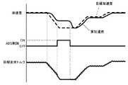
図10は、従来の車両自動走行制御装置における、目標加速度、実加速度、ABS制御のON/OFF、及び、目標要求トルクの夫々を示している。
ABS制御が実行されると、車輪のスリップを抑制するための要求トルクが車両に与えられるので、実加速度は、その路面において車輪のスリップを生じない一定の加速度となる。その為に、ABS制御が実行されると、実加速度が目標加速度に追従できなくなる。
ABS制御の実行中は、目標加速度の変化に関わらず、目標要求トルクは一定に保持されている。その為に、目標加速度が小さくなる側に変化してABS制御が実行されないような小さな加速度となっても、目標要求トルクが一定に保持されている。したがって、一旦、ABS制御が実行されると、そのABS制御をなかなか終了できず、実加速度が目標加速度に追従できない状態が継続されてしまう。
また、例えば、路面の摩擦係数が変化する等の外乱により車輪のスリップが抑制されることによってABS制御が終了されたとしても、実加速度と目標加速度との間には大きな偏差が生じており、実加速度が目標加速度に追従できるまでに時間がかかることになる。FIG. 10 shows each of the target acceleration, the actual acceleration, the ON / OFF of the ABS control, and the target required torque in the conventional vehicle automatic travel control device.
When the ABS control is executed, a required torque for suppressing wheel slip is applied to the vehicle, so that the actual acceleration is a constant acceleration that does not cause wheel slip on the road surface. For this reason, when ABS control is executed, the actual acceleration cannot follow the target acceleration.
During execution of the ABS control, the target required torque is kept constant regardless of the change in the target acceleration. For this reason, the target required torque is kept constant even when the acceleration becomes small such that the ABS is not executed due to the target acceleration becoming smaller. Therefore, once the ABS control is executed, it is difficult to end the ABS control, and the state where the actual acceleration cannot follow the target acceleration is continued.
Further, for example, even if the ABS control is terminated by suppressing the wheel slip due to a disturbance such as a change in the friction coefficient of the road surface, a large deviation occurs between the actual acceleration and the target acceleration. It takes time until the actual acceleration can follow the target acceleration.
本発明は、かかる点に着目してなされたものであり、その目的は、実加速度が目標加速度に良好に追従しながら、車両を自動走行させることができる車両自動走行制御装置を提供する点にある。 The present invention has been made paying attention to this point, and an object of the present invention is to provide an automatic vehicle traveling control device capable of automatically traveling the vehicle while the actual acceleration follows the target acceleration well. is there.
この目的を達成するために、本発明に係る車両自動走行制御装置の特徴構成は、目標加速度に基づくフィードフォワード演算値及び目標加速度と実加速度との偏差に基づくフィードバック演算値による各演算値から目標要求トルクを求める目標要求トルク演算手段と、前記求めた目標要求トルクに基づいて車両を自動走行させるとともに、該車両の何れかの車輪がスリップしたときに当該車輪のスリップを抑制するスリップ抑制制御を実行する自動走行制御手段と、を備える車両自動走行制御装置であって、前記目標要求トルク演算手段は、前記自動走行制御手段によって前記スリップ抑制制御が実行された場合、前記目標加速度と実加速度との偏差に基づくフィードバック演算値を保持し、該保持したフィードバック演算値及び前記フィードフォワード演算値による各演算値から前記目標要求トルクを求める点にある。 In order to achieve this object, the characteristic configuration of the automatic vehicle traveling control device according to the present invention is based on a feedforward calculation value based on a target acceleration and a calculation value based on a feedback calculation value based on a deviation between the target acceleration and the actual acceleration. A target request torque calculating means for determining a required torque, and a slip suppression control for automatically driving the vehicle based on the determined target request torque and for suppressing the slip of the wheel when any wheel of the vehicle slips. An automatic vehicle travel control device comprising: an automatic travel control device that executes the target requested torque calculation device, wherein when the slip suppression control is performed by the automatic travel control device, the target acceleration and the actual acceleration A feedback calculation value based on the deviation of the From the calculated value by the forward operation value to the point of obtaining the target required torque.
本構成の装置では、スリップ抑制制御の実行中に、フィードバック演算値を保持し、その保持したフィードバック演算値及びフィードフォワード演算値による各演算値から目標要求トルクを求め、目標要求トルクを目標加速度に応じて変化させる。例えば、目標加速度が小さくなると、目標要求トルクも小さくなる。したがって、目標要求トルク自体が車輪にスリップを生じない程度に小さくなって、スリップ抑制制御を終了させることができる。このように、本構成の装置であれば、スリップ抑制制御を早期に終了させ、実加速度が目標加速度に追従できない状態から抜け出し易くできる。また、スリップ抑制制御が終了するときには、保持したフィードバック演算値及びフィードフォワード演算値による各演算値から求めた目標要求トルクを車両に与えることができる。したがって、スリップ抑制制御が終了するときに、実加速度と目標加速度との偏差を小さくすることができ、短時間で実加速度を目標加速度に一致させることができる。
以上の構成を有する結果、本構成の制御装置は、実加速度が目標加速度に対して良好に追従し、安定した車両の自動走行を実現することができる。In the apparatus of this configuration, while the slip suppression control is being executed, the feedback calculation value is held, the target request torque is obtained from the calculated feedback calculation value and the feedforward calculation value, and the target request torque is set to the target acceleration. Change accordingly. For example, as the target acceleration decreases, the target required torque also decreases. Therefore, the target required torque itself becomes small enough to prevent the wheels from slipping, and the slip suppression control can be terminated. Thus, with the apparatus of this configuration, the slip suppression control can be terminated early, and the actual acceleration can easily escape from the state where the target acceleration cannot be followed. Further, when the slip suppression control is finished, the target required torque obtained from each calculated value based on the held feedback calculated value and feedforward calculated value can be given to the vehicle. Therefore, when the slip suppression control ends, the deviation between the actual acceleration and the target acceleration can be reduced, and the actual acceleration can be matched with the target acceleration in a short time.
As a result of having the above configuration, the control device of the present configuration can realize stable automatic driving of the vehicle, with the actual acceleration well following the target acceleration.
本発明に係る車両自動走行制御装置の更なる特徴構成は、前記自動走行制御手段は、前記スリップ抑制制御として、車両の減速中における車輪のスリップを抑制し、前記目標要求トルク演算手段は、前記目標要求トルクとして、車輪に付与する制動トルクを求める点にある。 According to a further characteristic configuration of the vehicle automatic travel control device according to the present invention, the automatic travel control means suppresses wheel slip during deceleration of the vehicle as the slip suppression control, and the target required torque calculation means includes the The point is to obtain a braking torque to be applied to the wheel as the target required torque.
本構成によれば、目標要求トルクとしての制動トルクを車輪に付与することによって、車両の自動走行に際して、減速時の車輪のスリップを抑制できる。しかも、車両を減速させるときに、実加速度が目標加速度に対して良好に追従しながら、車両を自動走行させることができる。 According to this configuration, by applying braking torque as the target required torque to the wheels, it is possible to suppress slipping of the wheels during deceleration during automatic traveling of the vehicle. In addition, when the vehicle is decelerated, the vehicle can automatically run while the actual acceleration favorably follows the target acceleration.
本発明に係る車両自動走行制御装置の更なる特徴構成は、前記自動走行制御手段は、前記スリップ抑制制御として、車両の加速中における駆動輪のスリップを抑制し、前記目標要求トルク演算手段は、前記目標要求トルクとして、駆動輪に付与する駆動トルクを求める点にある。 According to a further characteristic configuration of the vehicle automatic travel control device according to the present invention, the automatic travel control means suppresses slipping of driving wheels during acceleration of the vehicle as the slip suppression control, and the target required torque calculation means includes: The point is that a driving torque to be applied to the driving wheels is obtained as the target required torque.
本構成によれば、目標要求トルクとしての駆動トルクを駆動輪に付与することによって、車両の自動走行に際して、加速時の車輪のスリップを抑制できる。しかも、車両を加速させるときに、実加速度が目標加速度に対して良好に追従しながら、車両を自動走行させることができる。 According to this configuration, by applying a driving torque as the target required torque to the driving wheels, it is possible to suppress the slipping of the wheels during acceleration during automatic traveling of the vehicle. In addition, when the vehicle is accelerated, the vehicle can be automatically driven while the actual acceleration follows the target acceleration well.
本発明に係る車両自動走行制御装置の更なる特徴構成は、前記目標要求トルク演算手段は、前記自動走行制御手段による前記スリップ抑制制御が終了すると、前記保持されたフィードバック演算値に基づいてフィードバック演算を再開する点にある。 According to a further characteristic configuration of the vehicle automatic travel control device according to the present invention, the target required torque calculation means performs a feedback calculation based on the held feedback calculation value when the slip suppression control by the automatic travel control means ends. The point is to resume.
本構成によれば、自動走行制御手段によるスリップ抑制制御が終了すると、保持されたフィードバック演算値及びフィードフォワード演算値による各演算値から求めた目標要求トルクを車両に与えることができる。このように、目標要求トルク演算手段が、保持されたフィードバック演算値に基づいてフィードバック演算を再開することによって、外乱等により実加速度が変化しても、その外乱等による変化も考慮した状態で目標要求トルクを求めることができる。したがって、自動走行させるために必要となるトルクを的確に与えることができ、安定した自動走行を行える。 According to this configuration, when the slip suppression control by the automatic travel control means is completed, the target required torque obtained from each calculated value based on the held feedback calculated value and feedforward calculated value can be given to the vehicle. In this way, the target required torque calculation means restarts the feedback calculation based on the held feedback calculation value, so that even if the actual acceleration changes due to a disturbance or the like, the target is calculated in consideration of the change due to the disturbance or the like. The required torque can be obtained. Therefore, it is possible to accurately give the torque necessary for automatic traveling, and to perform stable automatic traveling.
本発明に係る車両自動走行制御装置の実施形態について説明する。
<本発明の概要>
本発明に係る車両自動走行制御装置は、フィードフォワード演算値及びフィードバック演算値の各演算値から求めた目標要求トルクを車両に与える動作をリアルタイムで繰り返し行うことにより、車両を自動走行させる自動走行制御を行う。この自動走行制御において、車輪のスリップを抑制するスリップ抑制制御を実行したときに、フィードバック演算値を保持し、保持したフィードバック演算値及びフィードフォワード演算値の各演算値から目標要求トルクを求め、目標要求トルクを目標加速度に応じて変化させておくことにより、実加速度の目標加速度に対する追従を良好にするようにしている。An embodiment of an automatic vehicle traveling control apparatus according to the present invention will be described.
<Outline of the present invention>
The vehicle automatic travel control apparatus according to the present invention is an automatic travel control that automatically travels a vehicle by repeatedly performing, in real time, a target required torque obtained from the calculated values of the feedforward calculated value and the feedback calculated value. I do. In this automatic travel control, when slip suppression control that suppresses wheel slip is executed, a feedback calculation value is held, and a target request torque is obtained from each calculation value of the held feedback calculation value and feedforward calculation value. By changing the required torque according to the target acceleration, the follow-up of the actual acceleration to the target acceleration is improved.
以下、本発明に係る車両自動走行制御装置を備えた車両について説明する。
<車両の概略構成>
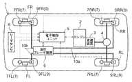
図1に示すように、車両1は、4つの車輪FR,FL,RR,RL、エンジン2、変速装置3、デファレンシャル装置4、電子制御ユニット5及び油圧ブレーキ装置6を備えている。本発明に係る車両自動走行制御装置は、電子制御ユニット5に相当する。
この車両1は、エンジン2の出力を変速装置3及びデファレンシャル装置4を介して右後輪RR及び左後輪RLに伝達する後輪駆動方式に構成している。車両1の駆動方式については、後輪駆動方式を例示したが、右前輪FR及び左前輪FLを駆動する前輪駆動方式や、4輪の夫々を駆動する4輪駆動方式とすることもできる。Hereinafter, the vehicle provided with the vehicle automatic travel control device according to the present invention will be described.
<Schematic configuration of vehicle>
As shown in FIG. 1, the
The
車両1には、各車輪の速度を検出する車輪速度センサ7を設けている。車輪速度センサ7は、右前輪FRに対応する車輪速度センサ7FR、左前輪FLに対応する車輪速度センサ7FL、右後輪RRに対応する車輪速度センサ7RR、左後輪RLに対応する車輪速度センサ7RLから構成してあり、各車輪速度センサ7にて各車輪の速度を各別に検出している。また、車両1には、先行車との車間距離等を検出するためのレーダセンサRを設けている。 The
<油圧ブレーキ装置の構成>
図2に基づき油圧ブレーキ装置6について説明する。
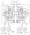
油圧ブレーキ装置6は、運転者のブレーキ操作力に応じてマスタシリンダ液圧を発生するマスタシリンダ8と、マスタシリンダ液圧を各車輪FR,FL,RR,RLのホイールシリンダ9に付与する液圧回路10とを有している。ホイールシリンダ9FR,9FL,9RR,9RLは、各車輪に設けている。<Configuration of hydraulic brake device>
The
The
マスタシリンダ8は、図示しない2つの液圧室を設けたタンデム型のシリンダである。このマスタシリンダ8は、ブレーキ操作力を図示しない倍力装置にて増幅した力によりマスタシリンダ液圧を発生する。また、マスタシリンダ8にブレーキ液を供給したり、マスタシリンダ8の余剰のブレーキ液を貯留する図示しないマスタリザーバを設けている。 The master cylinder 8 is a tandem cylinder provided with two hydraulic chambers (not shown). The master cylinder 8 generates a master cylinder hydraulic pressure by a force obtained by amplifying the brake operation force by a booster (not shown). Further, a master reservoir (not shown) for supplying brake fluid to the master cylinder 8 and storing excess brake fluid of the master cylinder 8 is provided.
液圧回路10は、マスタシリンダ8の一方の液圧室と右後輪RRのホイールシリンダ9RR及び左後輪RLのホイールシリンダ9RLとを連通する第1液圧回路10aと、マスタシリンダ8の他方の液圧室と右前輪FRのホイールシリンダ9FR及び左前輪FLのホイールシリンダ9FLとを連通する第2液圧回路10bとから構成している。 The
第1液圧回路10aには、連通状態を変更可能なリニア制御弁11aが設けられている。リニア制御弁11aに対して並列に、マスタシリンダ8側からホイールシリンダ9側へのブレーキ液の流れを許容し且つ逆方向の流れを禁止するマスタ用逆止弁12aを設けている。マスタ用逆止弁12aは、リニア制御弁11aが遮断状態であっても、マスタシリンダ8側からホイールシリンダ9側へのブレーキ液の流れを許容してマスタシリンダ液圧をホイールシリンダ9に付与するようにしている。 The first
第1液圧回路10aは、リニア制御弁11aよりもホイールシリンダ9側が第1分岐路13aと第2分岐路14aとに分岐され、第1分岐路13a及び第2分岐路14aの夫々がホイールシリンダ9RR,9RLの夫々に接続されている。第1分岐路13aには、連通位置と遮断位置との2位置に切換自在で第1常開制御弁15aを設けている。第1常開制御弁15aに対して並列に、ホイールシリンダ9側からマスタシリンダ8側へのブレーキ液の流れを許容し且つ逆方向の流れを禁止する第1逆止弁16aを設けている。第2分岐路14aには、第1分岐路13aと同様に、第2常開制御弁17aと第2逆止弁18aとを設けている。 In the first
第1分岐路13aの第1常開制御弁15aよりもホイールシリンダ9側から分岐された流路部分と、第2分岐路14aの第2常開制御弁17aよりもホイールシリンダ9側から分岐された流路部分とは、分岐合流路19aで合流する。分岐合流路19aにおいて第1分岐路13aから分岐された流路部分には、連通位置と遮断位置との2位置に切換自在な第1常閉制御弁20aを設けている。また、第2分岐路14aから分岐された流路部分にも、連通位置と遮断位置との2位置に切換自在な第2常閉制御弁21aを設けている。分岐合流路19aの合流部分には、液圧ポンプ22a、第3逆止弁23a、ダンパ24aを順に設け、第1液圧回路10aにおけるリニア制御弁11aと第1常開制御弁15a及び第2常開制御弁17aとの間に接続している。液圧ポンプ22aは、モータ25により回転駆動されて、ブレーキ液を所定の圧力に加圧して吐出するように構成している。分岐合流路19aにおいて、第1常閉制御弁20a及び第2常閉制御弁21aと液圧ポンプ22aとの間にはリザーバ26aを設けている。リザーバ26aは、第1液圧回路10aにおけるマスタシリンダ8とリニア制御弁11aとの間に接続している。 A flow path portion branched from the
以上、液圧回路10における第1液圧回路10aの構成について説明したが、第1液圧回路10aと第2液圧回路10bとは同様の構成としており、第2液圧回路10bにも、第1液圧回路10aと同様の部材を設けている。つまり、第2液圧回路10bにも、リニア制御弁11b、第1常開制御弁15b、第2常開制御弁17b、第1常閉制御弁20b、第2常閉制御弁21b、液圧ポンプ22b等の各部材を設けている。同一の部材については、第1液圧回路10aに設けた部材に対して算用数字の後に「a」を付しており、第2液圧回路10bに設けた部材に対して算用数字の後に「b」を付している。
以下、第1液圧回路10aに設けた部材と第2液圧回路10bに設けた部材との両方を示す場合には、算用数字の後の「a」及び「b」を省略して説明する。The configuration of the first
Hereinafter, when both the member provided in the first
モータ25については、単一のモータ25により第1液圧回路10aに設けた液圧ポンプ22aと第2液圧回路10bに設けた液圧ポンプ22bとを回転駆動するように構成している。
マスタシリンダ液圧を検出する液圧センサ27を設けている。この実施形態では、液圧センサ27を第1液圧回路10aに設けているが、第2液圧回路10bに設けることもできる。The
A
<車両の制御構成>
図3に基づき車両の制御構成について説明する。
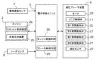
電子制御ユニット5は、CPU、ROM、RAM、入出力部を備えたマイクロコンピュータにて構成している。電子制御ユニット5には、各車輪速度センサ7、レーダセンサR及び液圧センサ27等の各種のセンサの検出信号が入力されるように構成している。電子制御ユニット5は、エンジン2の作動を制御するエンジン制御手段28、及び、油圧ブレーキ装置6の作動を制御するブレーキ制御手段29を備えている。エンジン制御手段28は、運転者のアクセル操作等により求められる駆動トルクを出力するためのスロットル開度や燃料噴射量等を求めて、エンジン2に備えたスロットル制御装置2a及び燃料噴射装置2bの作動を制御する。スロットル制御装置2aは、エンジン2のスロットル開度を制御する。燃料噴射装置2bは、エンジン2の燃料噴射量を制御する。<Vehicle control configuration>
The vehicle control configuration will be described with reference to FIG.
The
ブレーキ制御手段29は、運転者のブレーキ操作に拘わらず、各車輪に制動トルクを付与するように油圧ブレーキ装置6の作動を自動的に制御する。ブレーキ制御手段29は、リニア制御弁11、第1常開制御弁15、第2常開制御弁17、第1常閉制御弁20、第2常閉制御弁21、モータ25の夫々の作動を制御することにより、各車輪に各別に制動トルクを付与自在に構成している。 The brake control means 29 automatically controls the operation of the
例えば、図2に戻り、右後輪RRに制動トルクを付与する場合について説明する。
ホイールシリンダ圧力を増圧するときには、ブレーキ制御手段29が、モータ25を作動させるとともに、リニア制御弁11aを遮断状態とし、第1常開制御弁15aを連通位置とし且つ第1常閉制御弁20aを遮断位置とする。ホイールシリンダ圧力を保持するときには、ブレーキ制御手段29が、リニア制御弁11aを遮断状態とし、第1常開制御弁15aを遮断位置に切り換え且つ第1常閉制御弁20aを遮断位置とする。ホイールシリンダ圧力を減圧するときには、ブレーキ制御手段29が、リニア制御弁11aを遮断状態とし、第1常開制御弁15aを遮断位置に切り換え且つ第1常閉制御弁20aを連通位置に切り換える。For example, returning to FIG. 2, a case where braking torque is applied to the right rear wheel RR will be described.
When increasing the wheel cylinder pressure, the brake control means 29 activates the
<ABS制御>
ブレーキ制御手段29は、車両1の減速中における車輪のスリップを抑制するABS制御を行う。ブレーキ制御手段29は、モータ25の作動により液圧ポンプ22を作動させ且つリニア制御弁11を遮断状態とした状態で、第1常開制御弁15又は第2常開制御弁17及び第1常閉制御弁20又は第2常閉制御弁21の作動を制御して、ホイールシリンダ圧力を増圧、減圧及び保持の夫々に切り換えることにより、車輪に付与する制動トルクを制御する。このように、ブレーキ制御手段29は、減速スリップしている車輪に付与する制動トルクを制御して、車輪のスリップを抑制するためのスリップ抑制トルクを車両1に与えて減速スリップを抑制する。
ブレーキ制御手段29は、車輪速度センサ7による車輪速度と車体速度とを比較して、車輪の減速スリップ率が減速スリップ用設定値よりも大きいと、車輪が減速スリップしていると判別して、ABS制御を実行する。ブレーキ制御手段29は、車輪速度センサ7による車輪速度と車体速度とを比較して、車輪の減速スリップ率がABS終了用設定値よりも小さくなると、ABS制御を終了する。<ABS control>
The brake control means 29 performs ABS control for suppressing wheel slip during deceleration of the
The brake control means 29 compares the wheel speed by the
<トラクション制御>
エンジン制御手段28は、車両1の加速中における車輪のスリップを抑制するトラクション制御を行う。エンジン制御手段28は、車両1を走行させるために要求されている駆動トルクから駆動トルクダウン量を減算してエンジン2が出力する駆動トルクを演算する駆動トルクダウン演算を行い、その駆動トルクダウン演算にて演算した駆動トルクを出力するようにエンジン2の作動を制御する。このように、エンジン制御手段28は、エンジン2の出力を駆動トルクダウン量だけ低減して、車輪のスリップを抑制するためのスリップ抑制トルクを車両1に与えて加速スリップを抑制する。駆動トルクダウン量については、エンジン制御手段9が、加速スリップしている駆動輪の車輪速度がトラクション制御目標速度になるように、加速スリップしている駆動輪の車輪速度とトラクション制御目標速度との差に応じて駆動トルクダウン量を演算する。
エンジン制御手段28は、車輪速度センサ7による車輪速度と車体速度とを比較して、駆動輪の加速スリップ率が加速スリップ用設定値よりも大きいと、駆動輪が加速スリップしていると判別して、トラクション制御を実行する。エンジン制御手段28は、車輪速度センサ7による車輪速度と車体速度とを比較して、駆動輪の加速スリップ率がトラクション制御終了用設定値よりも小さくなると、トラクション制御を終了する。<Traction control>
The engine control means 28 performs traction control that suppresses wheel slip during acceleration of the
The engine control means 28 compares the wheel speed obtained by the
<自動走行制御>
車両1を自動走行させる自動走行制御について説明する。
例えば、運転者がアクセル操作を行わなくても、設定した車体速度に維持しながら走行するクルーズコントロール制御や、運転者がアクセル操作やブレーキ操作を行わなくても、先行車との車間距離を一定距離に維持しながら走行するACC制御等の自動走行制御を電子制御ユニット5が行うことにより、車両1を自動走行させるようにしている。<Automatic travel control>
Automatic traveling control for automatically traveling the
For example, even if the driver does not perform the accelerator operation, the cruise control control that runs while maintaining the set vehicle speed, or the distance between the preceding vehicle is constant even if the driver does not perform the accelerator operation or the brake operation. The
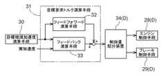
図4に示すように、自動走行制御を行うために、電子制御ユニット5は、目標加速度演算手段30、目標要求トルク演算手段31、制御量配分装置34を備えている。
目標加速度演算手段30は、クルーズコントロール制御においては、設定した車体速度を維持するように、現在の車体速度と設定した車体速度との差に基づいて目標加速度を求める。車体速度については、例えば、4つの車輪速度センサ7の夫々にて検出した車輪速度の平均速度を車体速度として求めることができる。
目標加速度演算手段30は、ACC制御においては、先行車との車間距離を一定距離に維持するように、先行車との車間距離及び先行車との相対速度等に基づいて目標加速度を求める。先行車との車間距離については、レーダセンサRの検出信号から求めることができる。先行車との相対速度は、先行車との車間距離を時間で微分することにより求めることができる。As shown in FIG. 4, the
In the cruise control control, the target acceleration calculation means 30 obtains the target acceleration based on the difference between the current vehicle speed and the set vehicle speed so as to maintain the set vehicle speed. As for the vehicle body speed, for example, the average speed of the wheel speeds detected by each of the four
In the ACC control, the target acceleration calculating means 30 obtains the target acceleration based on the inter-vehicle distance with the preceding vehicle, the relative speed with the preceding vehicle, and the like so as to maintain the inter-vehicle distance with the preceding vehicle at a constant distance. The inter-vehicle distance from the preceding vehicle can be obtained from the detection signal of the radar sensor R. The relative speed with the preceding vehicle can be obtained by differentiating the inter-vehicle distance from the preceding vehicle with respect to time.
目標要求トルク演算手段31は、目標加速度と実加速度との偏差に基づいて目標要求トルクを求めるフィードバック演算を行うフィードバック演算手段33、及び、目標加速度に応じて目標要求トルクを求めるフィードフォワード演算を行うフィードフォワード演算手段32を備えている。制御量配分装置34、エンジン制御手段28、及び、ブレーキ制御手段29から自動走行制御手段Dが構成されている。 The target required torque calculation means 31 performs a feedback calculation means 33 for performing a feedback calculation for obtaining the target required torque based on a deviation between the target acceleration and the actual acceleration, and performs a feedforward calculation for obtaining the target required torque according to the target acceleration. A feedforward calculation means 32 is provided. The control
目標加速度演算手段30は、自動走行させるための目標加速度を求めて目標要求トルク演算手段31に出力する。目標要求トルク演算手段31は、フィードバック演算手段33にて求めたフィードバック演算値とフィードフォワード演算手段32にて求めたフィードフォワード演算値との各演算値から目標要求トルクを求め、その求めた目標要求トルクを制御量配分装置34に出力する。制御量配分装置34は、目標要求トルクに基づいて、エンジン制御手段28に与える目標要求駆動トルクとブレーキ制御手段29に与える目標要求制動トルクに配分して出力する。例えば、車両1を加速させるときには、制御量配分装置34は、目標要求トルクに応じた目標要求駆動トルクをエンジン制御手段28に出力する。また、例えば、車両1を減速させるときには、制御量配分装置34は、目標要求トルクを目標要求駆動トルクと目標要求制動トルクとに配分してエンジン制御手段28及びブレーキ制御手段29の夫々に出力する。 The target acceleration calculating means 30 obtains a target acceleration for automatic running and outputs it to the target required torque calculating means 31. The target request torque calculation means 31 calculates the target request torque from the calculated values of the feedback calculation value obtained by the feedback calculation means 33 and the feedforward calculation value obtained by the feedforward calculation means 32, and the obtained target request Torque is output to the control
このようにして、自動走行制御中には、車両1に対して目標要求トルクをリアルタイムで繰り返し与えることにより、目標要求駆動トルクを出力するようにエンジン2の作動を制御したり、目標要求制動トルクを車輪に付与するように油圧ブレーキ装置6の作動を制御することにより、車両1を自動走行させるようにしている。 In this way, during automatic traveling control, the target required torque is repeatedly applied to the
この自動走行中に、ブレーキ制御手段29が車輪の減速スリップを判別するとABS制御を行い、エンジン制御手段28が駆動輪の加速スリップを判別するとトラクション制御を行う。このようにして、スリップ抑制制御として、ABS制御又はトラクション制御を行う。
ABS制御やトラクション制御では、車輪のスリップを抑制するためのスリップ抑制トルクを車両1に付与する。このとき、自動走行させているときでも車輪のスリップを抑制するために、車両に対して、目標要求トルクよりもスリップ抑制トルクを優先して与える。例えば、油圧ブレーキ装置2の液圧回路10では、ホイールシリンダ13に対して、第1常開制御弁15又は第2常開制御弁17及び第1常閉制御弁20又は第2常閉制御弁21の配設箇所を、液圧ポンプ22及びリニア制御弁11の配設箇所よりも近い側に配置している。このように、目標要求トルクよりもスリップ抑制トルクを優先してホイールシリンダ13に与えている。During this automatic travel, ABS control is performed when the brake control means 29 determines the deceleration slip of the wheel, and traction control is performed when the engine control means 28 determines the acceleration slip of the drive wheel. In this way, ABS control or traction control is performed as slip suppression control.
In ABS control and traction control, slip suppression torque for suppressing wheel slip is applied to the
目標要求トルク演算手段31は、ABS制御又はトラクション制御のスリップ抑制制御が実行された場合、フィードバック演算手段33によるフィードバック演算値を保持し、その保持したフィードバック演算値及びフィードフォワード演算手段32によるフィードフォワード演算値の各演算値から目標要求トルクを求める。つまり、目標要求トルク演算手段31は、スリップ抑制制御の実行中に、保持したフィードバック演算値とフィードフォワード演算値との合計値を目標要求トルクとして求める。
目標要求トルク演算手段31は、スリップ抑制制御が終了すると、保持したフィードバック演算値に基づいてフィードバック演算を再開する。つまり、目標要求トルク演算手段31は、スリップ抑制制御が終了した時点では、保持したフィードバック演算値とフィードフォワード演算値との合計値を目標要求トルクとして求め、その後は、再開されたフィードバック演算によるフィードバック演算値とフィードフォワード演算値との合計値を目標要求トルクとして求める。When the slip suppression control of the ABS control or the traction control is executed, the target required torque calculation means 31 holds the feedback calculation value by the feedback calculation means 33, and the held feedback calculation value and the feedforward by the feedforward calculation means 32 A target required torque is obtained from each calculated value. That is, the target required torque calculation means 31 calculates the total value of the held feedback calculation value and feedforward calculation value as the target request torque during the execution of the slip suppression control.
When the slip suppression control ends, the target required torque calculation means 31 restarts the feedback calculation based on the held feedback calculation value. That is, the target required torque calculation means 31 obtains the total value of the held feedback calculation value and the feedforward calculation value as the target request torque at the time when the slip suppression control is finished, and thereafter, feedback by the resumed feedback calculation. The total value of the calculated value and the feedforward calculated value is obtained as the target required torque.
図5は、自動走行の減速中にABS制御が行われたときの、目標加速度、実加速度、ABS制御のON/OFF、及び、目標要求トルクの夫々を示している。
ABS制御が実行されるまでは、フィードバック演算手段33にて求めたフィードバック演算値とフィードフォワード演算手段32にて求めたフィードフォワード演算値との合計値が目標要求トルクとして車両1に与えられる。ABS制御が実行されると、目標要求トルクに優先してスリップ抑制トルクが車両1に与えられる。このとき、目標要求トルク演算手段31が、フィードバック演算値を保持し、その保持したフィードバック演算値及びフィードフォワード演算値の各演算値から目標要求トルクを求めておくことにより、目標要求トルクを目標加速度に応じて変化させる。したがって、目標加速度が小さくなると、目標要求トルクも小さくなる。この結果、現実に車両1に与えられるトルクが減速スリップを生じさせない値に減少し、ABS制御を速やかに終了させることができる。しかも、ABS制御が終了するときには、目標加速度に応じて変化させている目標要求トルクを車両1に与えることができる。したがって、ABS制御が終了するときに、実加速度と目標加速度との偏差を小さくすることができ、短時間で実加速度が目標加速度に追従できる。FIG. 5 shows each of the target acceleration, the actual acceleration, the ON / OFF of the ABS control, and the target required torque when the ABS control is performed during the deceleration of the automatic travel.
Until the ABS control is executed, the total value of the feedback calculation value obtained by the feedback calculation means 33 and the feedforward calculation value obtained by the feedforward calculation means 32 is given to the
例えば、目標要求トルクは、以下のように求めることができる。
フィードバック演算手段33は、下記〔数1〕を用いてPID演算における各項を求め、下記〔数2〕を用いてフィードバック演算値を求める。
〔数1〕
P(n)=a1−a2
I(n)=I(n−1)+P(n)×Δt
D(n)=(P(n)−P(n−1))/Δt
ただし、P(n)が比例項であり、a1が目標加速度であり、a2が実加速度であり、I(n)が積分項であり、Δtがn回目からn+1回目までの経過時間であり、D(n)が微分項である。
〔数2〕
T1=Kp×P(n)+Ki×I(n)+Kd×D(n)
ただし、T1がフィードバック演算値として求めるトルクであり、Kpが比例ゲインであり、Kiが積分ゲインであり、Kdが微分ゲインである。For example, the target required torque can be obtained as follows.
The
[Equation 1]
P (n) = a1-a2
I (n) = I (n−1) + P (n) × Δt
D (n) = (P (n) −P (n−1)) / Δt
However, P (n) is a proportional term, a1 is a target acceleration, a2 is an actual acceleration, I (n) is an integral term, and Δt is an elapsed time from the nth time to the (n + 1) th time, D (n) is a differential term.
[Equation 2]
T1 = Kp * P (n) + Ki * I (n) + Kd * D (n)
However, T1 is a torque to be obtained as a feedback calculation value, Kp is a proportional gain, Ki is an integral gain, and Kd is a differential gain.
フィードフォワード演算手段32は、下記〔数3〕を用いてフィードフォワード演算値を求める。
〔数3〕
T2=(M×a1)×r
ただし、T2がフィードフォワード演算値として求めるトルクであり、Mが車両重量であり、a1が目標加速度であり、rが車輪の径である。The feedforward calculation means 32 calculates | requires a feedforward calculation value using following [Equation 3].
[Equation 3]
T2 = (M × a1) × r
However, T2 is the torque calculated | required as a feedforward calculation value, M is a vehicle weight, a1 is a target acceleration, and r is a diameter of a wheel.
図5では、目標要求トルクが目標加速度に応じて変化することによりABS制御が終了した場合を示したが、図6は、例えば、路面の摩擦係数が変化することによりABS制御が終了した場合を示している。図6も、図5と同様に、目標加速度、実加速度、ABS制御のON/OFF、及び、目標要求トルクの夫々を示している。 FIG. 5 shows a case where the ABS control is terminated by changing the target required torque according to the target acceleration. However, FIG. 6 shows a case where the ABS control is terminated by changing the friction coefficient of the road surface, for example. Show. FIG. 6 also shows the target acceleration, the actual acceleration, the ON / OFF of the ABS control, and the target required torque, respectively, as in FIG.
この場合も、ABS制御の実行中に、保持したフィードバック演算値及びフィードフォワード演算値の各演算値から目標要求トルクを求め、目標要求トルクを目標加速度に応じて変化させている。したがって、ABS制御が終了するときには、目標加速度に応じて変化させている目標要求トルクを車両1に与えることができるので、実加速度と目標加速度との偏差を小さくでき、短時間で実加速度が目標加速度に追従できる。 Also in this case, during the execution of the ABS control, the target required torque is obtained from the calculated values of the held feedback calculation value and feedforward calculation value, and the target request torque is changed according to the target acceleration. Therefore, when the ABS control is completed, the target required torque changed according to the target acceleration can be applied to the
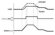
図5及び図6では、自動走行の減速中にABS制御が行われた場合を示したが、図7では、自動走行の加速中にトラクション制御が行われた場合を示している。図7も、図5と同様に、目標加速度、実加速度、トラクション制御のON/OFF、及び、目標要求トルクの夫々を示している。
トラクション制御が実行されると、目標要求トルク演算手段31が、保持したフィードバック演算値及びフィードフォワード演算値の各演算値から目標要求トルク演算する。目標加速度が小さくなるに伴って目標要求トルクも小さくなり、この結果、現実に車両1に与えられるトルクが加速スリップを生じさせない値に減少し、トラクション制御を速やかに終了させることができる。トラクション制御が終了するときには、保持したフィードバック演算値及びフィードフォワード演算値の各演算値から求めた目標要求トルクを車両1に与えることができる。このようにして、ABS制御を行うときだけでなく、トラクション制御を行うときにも、実加速度が目標加速度に対して良好に追従し、安定した車両の自動走行を行える。5 and 6 show the case where the ABS control is performed during the deceleration of the automatic traveling, but FIG. 7 shows the case where the traction control is performed during the acceleration of the automatic traveling. FIG. 7 also shows the target acceleration, the actual acceleration, the traction control ON / OFF, and the target required torque, as in FIG.
When the traction control is executed, the target required torque calculation means 31 calculates the target required torque from the calculated values of the held feedback calculation value and feedforward calculation value. As the target acceleration decreases, the target required torque also decreases. As a result, the torque actually applied to the
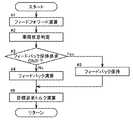
自動走行制御での目標要求トルク演算手段31における動作について、図8のフローチャートに基づいて説明する。自動走行制御では、目標加速度演算手段30にて目標加速度を求める動作と、図8のフローチャートにて示す目標要求トルク演算手段31における動作とを設定周期で繰り返し行っている。 The operation of the target required torque calculation means 31 in the automatic travel control will be described based on the flowchart of FIG. In the automatic travel control, the operation for obtaining the target acceleration by the target acceleration calculating means 30 and the operation in the target required torque calculating means 31 shown in the flowchart of FIG. 8 are repeated at a set cycle.
フィードフォワード演算手段32は、フィードフォワード演算によりフィードフォワード演算値を求める(#1)。目標要求トルク演算手段31は、車両状態判定を行い、その車両状態判定によってフィードバック保持要求がOFFにされていると、フィードバック演算手段33はフィードバック演算によりフィードバック演算値を求める(#2〜4)。車両状態判定によってフィードバック保持要求がONされていると、フィードバック演算手段33は、フィードバック演算において比例項及び微分項をゼロとし且つ積分項を前回の値としてフィードバック演算値を保持するフィードバック保持を行う(#5)。目標要求トルク演算手段31は、フィードフォワード演算値とフィードバック演算値との合計値を目標要求トルクとして求める(#6)。このとき、#4にてフィードバック演算を行っていると、そのフィードバック演算によるフィードバック演算値及びフィードフォワード演算値の合計値を目標要求トルクとする。#5にてフィードバック保持を行っていると、その保持したフィードバック演算値及びフィードフォワード演算値の合計値を目標要求トルクとする。 The feedforward calculation means 32 obtains a feedforward calculation value by feedforward calculation (# 1). The target request torque calculation means 31 performs vehicle state determination, and when the feedback hold request is turned OFF by the vehicle state determination, the feedback calculation means 33 obtains a feedback calculation value by feedback calculation (# 2-4). When the feedback hold request is turned ON by the vehicle state determination, the feedback calculation means 33 performs feedback hold that holds the feedback calculation value with the proportional term and the derivative term set to zero and the integral term as the previous value in the feedback calculation ( # 5). The target required torque calculating means 31 calculates the total value of the feedforward calculated value and the feedback calculated value as the target required torque (# 6). At this time, if the feedback calculation is performed in # 4, the total value of the feedback calculation value and the feedforward calculation value by the feedback calculation is set as the target required torque. If feedback holding is performed in # 5, the total value of the held feedback calculation value and feedforward calculation value is set as the target required torque.
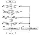
車両状態判定によるフィードバック保持要求のON/OFFについて図9のフローチャートに基づいて説明する。
目標要求トルク演算手段31は、ABS制御中であるか、又は、減速スリップ率が減速スリップ用設定値Th1よりも大きくなっていると、フィードバック保持要求をONとする(#11〜13)。減速スリップ率が減速スリップ用設定値Th1よりも大きくなると、ABS制御が実行されるので、減速スリップ率が減速スリップ用設定値Th1よりも大きくなったときは、現にABS制御を実行しようとしているときである。
目標要求トルク演算手段31は、トラクション制御中であるか、又は、加速スリップ率が加速スリップ用設定値Th2よりも大きくなっていると、フィードバック保持要求をONとする(#14,15,12)。加速スリップ率が加速スリップ用設定値Th2よりも大きくなると、トラクション制御が実行されるので、加速スリップ率が加速スリップ用設定値Th2よりも大きくなったときは、現にトラクション制御を実行しようとしているときである。
目標要求トルク演算手段31は、ABS制御中ではなく、減速スリップ率が減速スリップ用設定値未満であり、トラクション制御中ではなく、加速スリップ率が加速スリップ用設定値未満であると、フィードバック保持要求をOFFとする(#16)。The ON / OFF of the feedback holding request based on the vehicle state determination will be described based on the flowchart of FIG.
The target required torque calculating means 31 turns the feedback holding request ON when the ABS control is being performed or the deceleration slip rate is larger than the deceleration slip setting value Th1 (# 11-13). When the deceleration slip ratio becomes larger than the deceleration slip setting value Th1, the ABS control is executed. Therefore, when the deceleration slip ratio becomes larger than the deceleration slip setting value Th1, the ABS control is actually being executed. It is.
The target required torque calculating means 31 sets the feedback holding request to ON when the traction control is being performed or the acceleration slip ratio is larger than the acceleration slip setting value Th2 (# 14, 15, 12). . Since the traction control is executed when the acceleration slip ratio becomes larger than the acceleration slip setting value Th2, when the acceleration slip ratio becomes larger than the acceleration slip setting value Th2, the traction control is actually being executed. It is.
The target required torque calculation means 31 does not perform the ABS control, and if the deceleration slip rate is less than the set value for deceleration slip, does not perform the traction control, and the acceleration slip rate is less than the set value for acceleration slip, the feedback holding request Is set to OFF (# 16).
〔別実施形態〕
(1)上記実施形態において、例えば、目標加速度に係数を掛けた加速度に実加速度がなるように目標要求トルクを求めることができる。また、フィードフォワード演算値及びフィードバック演算値の各演算値から求めた目標要求トルクが設定値以下であると、その求めた目標要求トルクをそのまま目標要求トルクとし、フィードフォワード演算値及びフィードバック演算値の各演算値から求めた目標要求トルクが設定値よりも大きくなるときには、その設定値を目標要求トルクとすることもできる。[Another embodiment]
(1) In the above embodiment, for example, the target required torque can be obtained so that the actual acceleration is obtained by multiplying the target acceleration by a coefficient. In addition, if the target required torque obtained from the calculated values of the feedforward calculated value and the feedback calculated value is equal to or less than the set value, the obtained target required torque is directly used as the target required torque, and the feedforward calculated value and the feedback calculated value When the target required torque obtained from each calculated value is larger than the set value, the set value can be set as the target required torque.
(2)上記実施形態では、スリップ抑制制御として、ABS制御及びトラクション制御の両制御を行うようにしているが、スリップ抑制制御として、ABS制御及びトラクション制御の何れか一方のみを行うこともできる。(2) In the above embodiment, both ABS control and traction control are performed as slip suppression control. However, only one of ABS control and traction control can be performed as slip suppression control.
(3)上記実施形態において、例えば、第1液圧回路10aにて右前輪FR及び左後輪RLに設けたホイールシリンダ9FR,9RLにマスタシリンダ液圧を付与し、第2液圧回路10bにて左前輪FL及び右後輪RRに設けたホイールシリンダ9FL,9RRにマスタシリンダ液圧を付与するように、液圧回路10を構成することもできる。つまり、液圧回路10にてマスタシリンダ液圧をどのホイールシリンダに付与するように構成するかは適宜変更が可能である。(3) In the above embodiment, for example, the master cylinder hydraulic pressure is applied to the wheel cylinders 9FR and 9RL provided on the right front wheel FR and the left rear wheel RL in the first
本発明は、フィードフォワード演算値及びフィードバック演算値による各演算値から目標要求トルクを求める目標要求トルク演算手段と、その求めた目標要求トルクに基づいて車両を自動走行させる自動走行制御手段とを備え、目標要求トルク演算手段は、自動走行制御手段によって車両の何れかの車輪がスリップしたときに車輪のスリップを抑制するスリップ抑制制御が実行された場合に、実加速度が目標加速度に対して良好に追従しながら、車両を自動走行させることができる各種の車両自動走行制御装置に適応可能である。 The present invention includes a target required torque calculating means for obtaining a target required torque from each calculated value based on a feedforward calculated value and a feedback calculated value, and an automatic travel control means for automatically driving the vehicle based on the determined target required torque. The target required torque calculation means is configured so that the actual acceleration is excellent with respect to the target acceleration when the slip suppression control for suppressing the wheel slip is executed when any wheel of the vehicle slips by the automatic travel control means. The present invention can be applied to various types of vehicle automatic travel control devices that can automatically travel a vehicle while following.
31 目標要求トルク演算手段
D 自動走行制御手段31 Target request torque calculation means D Automatic travel control means
Claims (4)
Translated fromJapanese前記求めた目標要求トルクに基づいて車両を自動走行させるとともに、該車両の何れかの車輪がスリップしたときに当該車輪のスリップを抑制するスリップ抑制制御を実行する自動走行制御手段と、を備える車両自動走行制御装置であって、
前記目標要求トルク演算手段は、前記自動走行制御手段によって前記スリップ抑制制御が実行された場合、前記目標加速度と実加速度との偏差に基づくフィードバック演算値を保持し、該保持したフィードバック演算値及び前記フィードフォワード演算値による各演算値から前記目標要求トルクを求める車両自動走行制御装置。Target required torque calculating means for obtaining a target required torque from each calculated value based on a feedforward calculated value based on the target acceleration and a feedback calculated value based on a deviation between the target acceleration and the actual acceleration;
A vehicle that automatically travels based on the calculated target request torque, and that performs slip suppression control that suppresses slipping of any wheel when the vehicle slips. An automatic cruise control device,
The target required torque calculation means holds a feedback calculation value based on a deviation between the target acceleration and an actual acceleration when the slip suppression control is executed by the automatic travel control means, and the held feedback calculation value and the An automatic vehicle travel control device that obtains the target required torque from each calculated value based on a feedforward calculated value.
前記目標要求トルク演算手段は、前記目標要求トルクとして、車輪に付与する制動トルクを求める請求項1に記載の車両自動走行制御装置。The automatic travel control means suppresses wheel slip during deceleration of the vehicle as the slip suppression control,
The automatic vehicle travel control apparatus according to claim 1, wherein the target required torque calculation means obtains a braking torque to be applied to a wheel as the target required torque.
前記目標要求トルク演算手段は、前記目標要求トルクとして、駆動輪に付与する駆動トルクを求める請求項1に記載の車両自動走行制御装置。The automatic travel control means suppresses slipping of the drive wheels during acceleration of the vehicle as the slip suppression control,
The automatic vehicle travel control apparatus according to claim 1, wherein the target required torque calculation means obtains a drive torque to be applied to the drive wheels as the target required torque.
Priority Applications (3)
| Application Number | Priority Date | Filing Date | Title |
|---|---|---|---|
| JP2007240892AJP2009067358A (en) | 2007-09-18 | 2007-09-18 | Automatic vehicle travel controller |
| DE102008047412ADE102008047412B4 (en) | 2007-09-18 | 2008-09-16 | Control device for a vehicle automatic operation |
| US12/211,644US8155854B2 (en) | 2007-09-18 | 2008-09-16 | Vehicle automatic operation control device |
Applications Claiming Priority (1)
| Application Number | Priority Date | Filing Date | Title |
|---|---|---|---|
| JP2007240892AJP2009067358A (en) | 2007-09-18 | 2007-09-18 | Automatic vehicle travel controller |
Publications (1)
| Publication Number | Publication Date |
|---|---|
| JP2009067358Atrue JP2009067358A (en) | 2009-04-02 |
Family
ID=40418355
Family Applications (1)
| Application Number | Title | Priority Date | Filing Date |
|---|---|---|---|
| JP2007240892APendingJP2009067358A (en) | 2007-09-18 | 2007-09-18 | Automatic vehicle travel controller |
Country Status (3)
| Country | Link |
|---|---|
| US (1) | US8155854B2 (en) |
| JP (1) | JP2009067358A (en) |
| DE (1) | DE102008047412B4 (en) |
Cited By (6)
| Publication number | Priority date | Publication date | Assignee | Title |
|---|---|---|---|---|
| JP2011255808A (en)* | 2010-06-10 | 2011-12-22 | Denso Corp | Braking/driving control apparatus for vehicle |
| WO2015016325A1 (en)* | 2013-07-31 | 2015-02-05 | 株式会社アドヴィックス | Vehicle control device |
| JP6031166B1 (en)* | 2015-09-11 | 2016-11-24 | 富士重工業株式会社 | Vehicle automatic operation control device |
| JP2018521902A (en)* | 2015-07-07 | 2018-08-09 | 日産自動車株式会社 | Predictive starting method for heat engine |
| JP2019093740A (en)* | 2017-11-17 | 2019-06-20 | トヨタ自動車株式会社 | Automatic driving system |
| WO2020138142A1 (en)* | 2018-12-27 | 2020-07-02 | 株式会社アドヴィックス | Braking control device |
Families Citing this family (15)
| Publication number | Priority date | Publication date | Assignee | Title |
|---|---|---|---|---|
| EP2470403B1 (en)* | 2009-08-24 | 2017-05-10 | Kelsey-Hayes Company | Slip control system with attenuator |
| US9162573B2 (en)* | 2010-06-03 | 2015-10-20 | Polaris Industries Inc. | Electronic throttle control |
| GB2505022B (en) | 2012-08-16 | 2015-01-14 | Jaguar Land Rover Ltd | Speed control system and method for operating the same |
| US9205717B2 (en) | 2012-11-07 | 2015-12-08 | Polaris Industries Inc. | Vehicle having suspension with continuous damping control |
| GB2515105B (en)* | 2013-06-14 | 2016-04-13 | Jaguar Land Rover Ltd | Vehicle control including control over a rate of torque decrease |
| GB2519054A (en)* | 2013-07-26 | 2015-04-15 | Equipmake Ltd | Energy saving in vehicles |
| JP6236672B2 (en)* | 2013-09-26 | 2017-11-29 | 日立オートモティブシステムズ株式会社 | Control device for electric vehicle |
| EP3212484A2 (en) | 2014-10-31 | 2017-09-06 | Polaris Industries Inc. | System and method for controlling a vehicle |
| JP6380309B2 (en)* | 2015-09-15 | 2018-08-29 | トヨタ自動車株式会社 | Vehicle control device |
| GB2552011B (en)* | 2016-07-07 | 2019-08-28 | Jaguar Land Rover Ltd | A controller for a vehicle system |
| CN110121438B (en) | 2016-11-18 | 2023-01-31 | 北极星工业有限公司 | vehicles with adjustable suspension |
| US10406884B2 (en) | 2017-06-09 | 2019-09-10 | Polaris Industries Inc. | Adjustable vehicle suspension system |
| US10987987B2 (en) | 2018-11-21 | 2021-04-27 | Polaris Industries Inc. | Vehicle having adjustable compression and rebound damping |
| CN120716852A (en) | 2020-05-20 | 2025-09-30 | 北极星工业有限公司 | System and method for adjustable suspension for off-road recreational vehicle |
| WO2022016155A1 (en) | 2020-07-17 | 2022-01-20 | Polaris Industries Inc. | Adjustable suspensions and vehicle operation for off-road recreational vehicles |
Citations (5)
| Publication number | Priority date | Publication date | Assignee | Title |
|---|---|---|---|---|
| JPS62244724A (en)* | 1986-04-16 | 1987-10-26 | Nissan Motor Co Ltd | Controller for continuously variable transmission |
| JPH02201038A (en)* | 1989-01-31 | 1990-08-09 | Mitsubishi Motors Corp | Engine output control device |
| JP2002005277A (en)* | 2000-06-22 | 2002-01-09 | Denso Corp | Vehicle control system |
| JP2005170194A (en)* | 2003-12-10 | 2005-06-30 | Nissan Motor Co Ltd | Driving force control device |
| JP2008055994A (en)* | 2006-08-30 | 2008-03-13 | Toyota Motor Corp | Vehicle braking / driving force control device |
Family Cites Families (6)
| Publication number | Priority date | Publication date | Assignee | Title |
|---|---|---|---|---|
| JPH01111540A (en)* | 1987-10-26 | 1989-04-28 | Nissan Motor Co Ltd | Vehicle constant speed running device |
| US5400865A (en)* | 1989-01-31 | 1995-03-28 | Mitsubishi Jidosha Kogyo Kabushiki Kaisha | Engine output control apparatus |
| JPH061229A (en) | 1992-06-19 | 1994-01-11 | Fuji Heavy Ind Ltd | Method for controlling automatic braking device |
| JP3937524B2 (en)* | 1997-09-30 | 2007-06-27 | トヨタ自動車株式会社 | Vehicle braking / driving force control device |
| DE10228348A1 (en)* | 2002-06-25 | 2004-01-15 | Robert Bosch Gmbh | Method and device for regulating the driving speed of a vehicle |
| JP4554997B2 (en)* | 2004-06-10 | 2010-09-29 | 日産自動車株式会社 | Vehicle driving force control device |
- 2007
- 2007-09-18JPJP2007240892Apatent/JP2009067358A/enactivePending
- 2008
- 2008-09-16USUS12/211,644patent/US8155854B2/ennot_activeExpired - Fee Related
- 2008-09-16DEDE102008047412Apatent/DE102008047412B4/ennot_activeExpired - Fee Related
Patent Citations (5)
| Publication number | Priority date | Publication date | Assignee | Title |
|---|---|---|---|---|
| JPS62244724A (en)* | 1986-04-16 | 1987-10-26 | Nissan Motor Co Ltd | Controller for continuously variable transmission |
| JPH02201038A (en)* | 1989-01-31 | 1990-08-09 | Mitsubishi Motors Corp | Engine output control device |
| JP2002005277A (en)* | 2000-06-22 | 2002-01-09 | Denso Corp | Vehicle control system |
| JP2005170194A (en)* | 2003-12-10 | 2005-06-30 | Nissan Motor Co Ltd | Driving force control device |
| JP2008055994A (en)* | 2006-08-30 | 2008-03-13 | Toyota Motor Corp | Vehicle braking / driving force control device |
Cited By (14)
| Publication number | Priority date | Publication date | Assignee | Title |
|---|---|---|---|---|
| JP2011255808A (en)* | 2010-06-10 | 2011-12-22 | Denso Corp | Braking/driving control apparatus for vehicle |
| WO2015016325A1 (en)* | 2013-07-31 | 2015-02-05 | 株式会社アドヴィックス | Vehicle control device |
| JP2015030312A (en)* | 2013-07-31 | 2015-02-16 | 株式会社アドヴィックス | Vehicle control device |
| CN105431338A (en)* | 2013-07-31 | 2016-03-23 | 株式会社爱德克斯 | Vehicle control device |
| US9771056B2 (en) | 2013-07-31 | 2017-09-26 | Advics Co., Ltd. | Vehicle control device |
| JP2018521902A (en)* | 2015-07-07 | 2018-08-09 | 日産自動車株式会社 | Predictive starting method for heat engine |
| US9834219B2 (en) | 2015-09-11 | 2017-12-05 | Subaru Corporation | Vehicle automatic driving control apparatus |
| JP6031166B1 (en)* | 2015-09-11 | 2016-11-24 | 富士重工業株式会社 | Vehicle automatic operation control device |
| JP2019093740A (en)* | 2017-11-17 | 2019-06-20 | トヨタ自動車株式会社 | Automatic driving system |
| US11768500B2 (en) | 2017-11-17 | 2023-09-26 | Toyota Jidosha Kabushiki Kaisha | Autonomous driving system |
| WO2020138142A1 (en)* | 2018-12-27 | 2020-07-02 | 株式会社アドヴィックス | Braking control device |
| JP2020104642A (en)* | 2018-12-27 | 2020-07-09 | 株式会社アドヴィックス | Braking control device |
| JP7218570B2 (en) | 2018-12-27 | 2023-02-07 | 株式会社アドヴィックス | Braking control device |
| US12017631B2 (en) | 2018-12-27 | 2024-06-25 | Advics Co., Ltd. | Braking control device |
Also Published As
| Publication number | Publication date |
|---|---|
| DE102008047412B4 (en) | 2013-06-20 |
| DE102008047412A1 (en) | 2009-04-09 |
| US20090076699A1 (en) | 2009-03-19 |
| US8155854B2 (en) | 2012-04-10 |
Similar Documents
| Publication | Publication Date | Title |
|---|---|---|
| JP2009067358A (en) | Automatic vehicle travel controller | |
| US10259438B2 (en) | Brake control device | |
| US7587267B2 (en) | Vehicle speed control apparatus | |
| JP2009051310A (en) | Vehicle traveling controller | |
| JP5109101B2 (en) | Vehicle control device | |
| US8065066B2 (en) | Vehicle running control device for running extremely low speed to stop | |
| US8924116B2 (en) | Motion control apparatus for vehicle | |
| JP2001171504A (en) | Road surface friction coefficient estimation device | |
| JP4792979B2 (en) | Vehicle motion control device | |
| JP2009024556A (en) | Slip control device and slip control method | |
| CN101253066A (en) | System for controlling vehicle downhill driving | |
| JP2007118791A (en) | Automatic braking device for vehicle | |
| US9120470B2 (en) | Vehicle brake hydraulic pressure controller | |
| JP2015020626A (en) | Traction control system | |
| US8751132B2 (en) | Method for ascertaining a wheel reference speed of a wheel on a vehicle having a hydrostatic drive, and device for ascertaining a wheel reference speed of a wheel of a vehicle having a hydrostatic drive | |
| JP2011213199A (en) | Motion control device of vehicle | |
| JP2007120416A (en) | Automatic brake device for vehicle | |
| JP4604926B2 (en) | Vehicle traction control device and vehicle traction control method | |
| JP2002137721A (en) | Vehicle motion control device | |
| JP2012131385A (en) | Vehicle control system | |
| JP5397074B2 (en) | Vehicle motion control device | |
| JP2019182050A (en) | Brake control device and brake control method | |
| JP7099028B2 (en) | Vehicle travel path determination device | |
| JP3409601B2 (en) | Vehicle behavior control device | |
| JP7099096B2 (en) | Vehicle traction control device |
Legal Events
| Date | Code | Title | Description |
|---|---|---|---|
| A621 | Written request for application examination | Free format text:JAPANESE INTERMEDIATE CODE: A621 Effective date:20091201 | |
| A131 | Notification of reasons for refusal | Free format text:JAPANESE INTERMEDIATE CODE: A131 Effective date:20110915 | |
| A521 | Written amendment | Free format text:JAPANESE INTERMEDIATE CODE: A523 Effective date:20111114 | |
| A131 | Notification of reasons for refusal | Free format text:JAPANESE INTERMEDIATE CODE: A131 Effective date:20111222 | |
| A02 | Decision of refusal | Free format text:JAPANESE INTERMEDIATE CODE: A02 Effective date:20120412 |