JP2009065695A - Camera and camera control method - Google Patents
Camera and camera control methodDownload PDFInfo
- Publication number
- JP2009065695A JP2009065695AJP2008275679AJP2008275679AJP2009065695AJP 2009065695 AJP2009065695 AJP 2009065695AJP 2008275679 AJP2008275679 AJP 2008275679AJP 2008275679 AJP2008275679 AJP 2008275679AJP 2009065695 AJP2009065695 AJP 2009065695A
- Authority
- JP
- Japan
- Prior art keywords
- light source
- imaging system
- digital
- white balance
- gain
- Prior art date
- Legal status (The legal status is an assumption and is not a legal conclusion. Google has not performed a legal analysis and makes no representation as to the accuracy of the status listed.)
- Pending
Links
Images


Landscapes
- Testing, Inspecting, Measuring Of Stereoscopic Televisions And Televisions (AREA)
- Color Television Image Signal Generators (AREA)
- Processing Of Color Television Signals (AREA)
- Stereoscopic And Panoramic Photography (AREA)
Abstract
Description
Translated fromJapanese本発明は、複数の撮像光学系により各々互いに異なる位置から被写体像を示す画像情報を取得し、取得された複数の画像情報のホワイトバランス調整を、予め設定された調整値を用いて行なうカメラ及びカメラの制御方法に関する。 The present invention obtains image information indicating a subject image from a position different from each other by a plurality of imaging optical systems, and performs a white balance adjustment of the obtained plurality of image information using a preset adjustment value, and The present invention relates to a camera control method.
近年、立体画像に対する関心が高まっており、互いに異なる2位置に設けられた2つのカメラユニットを用いて右目用の画像及び左目用の画像を取得することにより立体画像が撮影可能なカメラが実用化されている。 In recent years, interest in stereoscopic images has increased, and a camera that can capture stereoscopic images by acquiring right-eye images and left-eye images using two camera units provided at two different positions has been put into practical use. Has been.
一方、通常の2次元の画像を取得するカメラには、画像の色味を調整するホワイトバランス制御機能が一般的な機能として備えられており、上記立体画像が撮影可能なカメラにおいてもホワイトバランス制御を行なうことにより適切な色味の画像が得られる。 On the other hand, a camera that acquires a normal two-dimensional image is provided with a white balance control function that adjusts the color of the image as a general function. By performing the above, an image having an appropriate color can be obtained.
従来、立体画像が撮影可能なカメラにおけるホワイトバランス制御に適用し得る技術として、特許文献1には、通常の(2次元の)画像を取得するカメラにおいて、まず、シャッタボタンの半押し時に、R,G,Bの積算値に基づくR/G/Bの比とEV値とに基づいて光源種を判別し、光源種に応じたホワイトバランス調整値に従って前段ゲインブロックのアナログアンプゲインを制御してホワイトバランスの粗補正を行ない、その後、シャッタボタンの全押し時に、記録用画像の撮り込み処理を行ない、当該処理により撮り込まれた画像データにおけるR/G/Bに基づき計算したホワイトバランス補正値に従って後段ゲインブロックのアナログアンプゲインを制御してホワイトバランスの微補正を行なうようにした技術が開示されている。 Conventionally, as a technique that can be applied to white balance control in a camera capable of capturing a stereoscopic image,
また、特許文献2には、通常の(2次元の)画像を取得するカメラにおいて、被写体を照明する光の色温度情報を測定し、当該色温度情報に基づいてホワイトバランス調整を行なうようにした技術が開示されている。 In
さらに、特許文献3には、通常の(2次元の)画像を取得するカメラにおいて、複数の光源に対応付けて複数の色温度情報を記憶しておき、被写体を照射する光源の色温度情報を設定し、設定された色温度情報に基づいてホワイトバランス補正の補正値を求め、上記補正値に従って利得制御回路の利得を制御するようにした技術が開示されている。
しかしながら、上記特許文献1乃至特許文献3に記載の技術では、複数のカメラユニットにより取得された複数の画像情報に対するホワイトバランス調整については何ら考慮されていないため、単純に上記特許文献1乃至特許文献3に記載の技術を適用して、立体画像が撮影可能なカメラのホワイトバランス調整を行なった場合、各画像情報の調整結果にずれが生じてしまう、という問題点があった。 However, in the techniques described in
すなわち、カメラを構成する各カメラユニットでは、それぞれのレンズ、OLPF(Optical Low Pass Filter)やIRカットフィルタ等の光学素子の分光特性、或いは、CCDそのものの分光特性の違いにより、同一のゲインでホワイトバランス調整を行なった後の各画像の色味にずれが生じてしまうことがある。 That is, in each camera unit constituting the camera, white with the same gain due to the difference in the spectral characteristics of each lens, optical elements such as an OLPF (Optical Low Pass Filter) and IR cut filter, or the spectral characteristics of the CCD itself. There may be a shift in the color of each image after the balance adjustment.
当該色味のずれは、これらの画像に基づいて生成した立体画像情報が不適切なものになり、当該立体画像情報により示される画像の立体視を困難にしてしまうことがある。 The color shift may make the stereoscopic image information generated based on these images inappropriate and make stereoscopic viewing of the image indicated by the stereoscopic image information difficult.
本発明は上記問題点を解決するためになされたものであり、ホワイトバランス制御を高精度に行なうことができるカメラ及びカメラの制御方法を提供することを目的とする。 The present invention has been made to solve the above-described problems, and an object thereof is to provide a camera and a camera control method capable of performing white balance control with high accuracy.
上記目的を達成するために、請求項1記載のカメラは、各々互いに異なる位置から被写体像を示す画像情報を取得するための複数の撮像光学系と、予め定められた複数の光源種の何れかを選択する選択情報を入力するための入力手段と、前記複数の光源種と、前記複数の撮像光学系により取得された複数の画像情報のホワイトバランス調整を行うために用いられる、各光源種に応じた調整値とを関連付けて予め記憶した記憶手段と、前記入力手段から入力された選択情報によって示される光源種に応じた調整値を前記記憶手段から読み出して設定する設定手段と、前記設定手段により設定された調整値を用いて前記ホワイトバランス調整を行なう調整手段と、を備えている。 To achieve the above object, the camera according to
従って、請求項1に記載のカメラは、ホワイトバランス制御を高精度に行なうことができる。また、各撮像光学系の調整値を複数の光源種に応じて設定することができるので、光源の種類によって異なる色温度に応じてホワイトバランス制御を高精度に行なうことができる。更に、選択情報により示される光源種と関連付けされた調整値をそのまま設定すればよいので、調整値の設定処理が容易かつ高速に行なえる。 Therefore, the camera according to
なお、上記記憶手段には、RAM(Random Access Memory)、EEPROM(Electrically Erasable and Programmable Read Only Memory)、フラッシュEEPROM(Flash EEPROM)等の半導体記憶素子、フロッピィディスク、CD−R(Compact Disc-Recordable)、CD−RW(Compact Disc-ReWritable)、光磁気ディスク等の可搬記録媒体やハードディスク等の固定記録媒体等を用いることができる。 The storage means includes a RAM (Random Access Memory), an EEPROM (Electrically Erasable and Programmable Read Only Memory), a semiconductor storage element such as a flash EEPROM (Flash EEPROM), a floppy disk, and a CD-R (Compact Disc-Recordable). A portable recording medium such as a CD-RW (Compact Disc-ReWritable) or a magneto-optical disk, a fixed recording medium such as a hard disk, or the like can be used.
一方、上記目的を達成するために、請求項2に記載のカメラの制御方法は、各々互いに異なる位置から被写体像を示す画像情報を取得するための複数の撮像光学系と、予め定められた複数の光源種の何れかを選択する選択情報を入力するための入力手段と、を備えたカメラの制御方法であって、前記複数の光源種と、前記複数の撮像光学系により取得された複数の画像情報のホワイトバランス調整を行うために用いられる、各光源種に応じた調整値とを関連付けて予め記憶しておき、前記入力手段から入力された選択情報によって示される光源種に応じた調整値を記憶した内容に基づいて設定し、設定された調整値を用いて前記ホワイトバランス調整を行なうものである。 On the other hand, in order to achieve the above object, a camera control method according to
したがって、請求項2に記載のカメラの制御方法によれば、上記請求項1に記載の発明と同様に作用するので、請求項1に係る発明と同様に、ホワイトバランス制御を高精度に行なうことができる。 Therefore, according to the camera control method of the second aspect, since it operates in the same manner as the first aspect of the invention, the white balance control can be performed with high accuracy as in the first aspect of the invention. Can do.
以上説明したように、本発明に係るカメラ及びカメラの制御方法は、ホワイトバランス制御を高精度に行なうことができる、という優れた効果を有する。 As described above, the camera and the camera control method according to the present invention have an excellent effect that white balance control can be performed with high accuracy.
以下、図面を参照して、発明を実施するための最良の形態について詳細に説明する。なお、ここでは、本発明を立体静止画像及び通常(2次元)の静止画像の撮影を行う機能を有するデジタル電子スチルカメラ(以下、単に「デジタルカメラ」という。)に適用した場合について説明する。 The best mode for carrying out the invention will be described below in detail with reference to the drawings. Here, a case where the present invention is applied to a digital electronic still camera (hereinafter simply referred to as “digital camera”) having a function of capturing a stereoscopic still image and a normal (two-dimensional) still image will be described.
(第1の実施の形態)(First embodiment)
まず、図1を参照して、本実施の形態に係るデジタルカメラ10の外観上の構成を説明する。同図に示すように、デジタルカメラ10の正面には、各々被写体像を結像させるための一対のレンズ12A及びレンズ12Bと、撮影する被写体の構図を決定するために用いられるファインダ70と、が備えられている。 First, an external configuration of the
また、デジタルカメラ10の上面には、撮影を実行する際に撮影者によって押圧操作されるレリーズボタン(所謂シャッター)52Aと、電源スイッチ52Eと、が備えられている。 On the top surface of the
なお、本実施の形態に係るレリーズボタン52Aは、中間位置まで押下される状態(以下、「半押し状態」という。)と、当該中間位置を超えた最終押下位置まで押下される状態(以下、「全押し状態」という。)と、の2段階の押圧操作が検出可能に構成されている。 Note that the
そして、本実施の形態に係るデジタルカメラ10では、後述する撮影モードが設定されている場合にレリーズボタン52Aを半押し状態にすることによりAE(Automatic Exposure、自動露出)機能が働いて露出状態(シャッタースピード、絞りの状態)が設定された後、AF(Auto Focus、自動合焦)機能が働いて合焦制御され、その後、引き続き全押し状態にすると露光(撮影)が行われる。 In the
一方、デジタルカメラ10の背面には、前述のファインダ70の接眼部と、撮影によって得られたデジタル画像データにより示される被写体像や各種メニュー画面、メッセージ等を表示するための液晶ディスプレイ(以下、「LCD」という。)30と、立体の静止画像の撮影を行うモードである立体撮影モード、2次元の静止画像の撮影を行うモードである通常撮影モード及び撮影によって得られたデジタル画像データにより示される被写体像をLCD30に表示(再生)するモードである再生モードの何れかのモードに設定するために操作されるモード切替スイッチ52Bと、十字カーソルボタン52Cと、撮影時に被写体像のズーミング(拡大及び縮小)を行うときに操作されるズームスイッチ52Dと、が備えられている。 On the other hand, on the back of the
また、十字カーソルボタン52Cは、LCD30の表示領域における上・下・左・右の4方向の移動方向を示す4つの矢印キー及び当該4つの矢印キーの中央部に位置された決定キーの合計5つのキーを含んで構成されている。また、ズームスイッチ52Dは、同図の‘T’の位置に対応し、かつ被写体像を拡大するときに操作されるテレ・スイッチと、同図の‘W’の位置に対応し、かつ被写体像を縮小するときに操作されるワイド・スイッチと、により構成されている。 The cross-cursor button 52C has a total of five arrow keys indicating four movement directions of up, down, left, and right in the display area of the
一方、デジタルカメラ10の側面には、撮影によって得られたデジタル画像データが記録可能な記録メディア(ここでは、当該デジタル画像データが画像ファイルとして記録される記録メディア。)を装着することができるスロットSLが設けられている。 On the other hand, on the side of the
次に、図2を参照して、本実施の形態に係るデジタルカメラ10の電気系の構成を説明する。 Next, the configuration of the electrical system of the
同図に示すように、デジタルカメラ10は、前述のレンズ12Aを含んで構成された光学ユニット13Aと、レンズ12Aの光軸後方に配設されたCCD(電荷結合素子)14Aと、相関二重サンプリング回路(以下、「CDS」という。)16Aと、入力されたアナログ信号をデジタルデータに変換するアナログ/デジタル変換器(以下、「ADC」という。)18Aと、を含んで構成された第1撮像系88Aを備えている。また、デジタルカメラ10は、前述のレンズ12Bを含んで構成された光学ユニット13Bと、レンズ12Bの光軸後方に配設されたCCD14Bと、CDS16Bと、ADC18Bと、を含んで構成された第2撮像系88Bを備えている。 As shown in the figure, the
すなわち、本実施の形態に係るデジタルカメラ10は、互いに同様の構成とされた第1撮像系88A及び第2撮像系88Bの2つの撮像系を備えており、これらを用いることによって立体撮影を可能としている。なお、通常撮影モードが設定されており、通常の2次元の撮影を行う際には、第1撮像系88A及び第2撮像系88Bの何れか一方が選択的に用いられる。 That is, the
第1撮像系88Aにおいて、CCD14Aの出力端はCDS16Aの入力端に、CDS16Aの出力端はADC18Aの入力端に、各々接続されている。同様に、第2撮像系88Bにおいても、CCD14Bの出力端はCDS16Bの入力端に、CDS16Bの出力端はADC18Bの入力端に、各々接続されている。 In the first imaging system 88A, the output end of the CCD 14A is connected to the input end of the CDS 16A, and the output end of the CDS 16A is connected to the input end of the ADC 18A. Similarly, in the second imaging system 88B, the output end of the CCD 14B is connected to the input end of the CDS 16B, and the output end of the CDS 16B is connected to the input end of the
ここで、CDS16A及びCDS16Bによる相関二重サンプリング処理は、固体撮像素子の出力信号に含まれるノイズ(特に熱雑音)等を軽減することを目的として、固体撮像素子の1画素毎の出力信号に含まれるフィードスルー成分レベルと画素信号成分レベルとの差をとることにより正確な画素データを得る処理である。 Here, the correlated double sampling processing by the CDS 16A and the CDS 16B is included in the output signal for each pixel of the solid-state image sensor for the purpose of reducing noise (particularly thermal noise) included in the output signal of the solid-state image sensor. This process is to obtain accurate pixel data by taking the difference between the feedthrough component level and the pixel signal component level.
一方、デジタルカメラ10は、ADC18A及びADC18Cの各々の出力端に入力端が接続されると共に、所定容量のラインバッファを内蔵し、入力されたデジタル画像データを後述する第2メモリ40の所定領域に直接記憶させる制御を行う画像入力コントローラ20と、通常撮影モードが設定されている際に、適用されている第1撮像系88A及び第2撮像系88Bの何れか一方によって取得されたデジタル画像データに対して各種画像処理を施す画像信号処理回路22と、立体撮影モードが設定されている際に、第1撮像系88A及び第2撮像系88Bの双方によって取得された2つのデジタル画像データに対して各種画像処理を施して合成する立体画像信号処理回路23と、所定の圧縮形式でデジタル画像データに対して圧縮処理を施す一方、圧縮処理されたデジタル画像データに対して圧縮形式に応じた形式で伸張処理を施す圧縮・伸張処理回路24と、を備えている。 On the other hand, the
なお、画像信号処理回路22及び立体画像信号処理回路23は、それぞれ入力されたR、G、Bの各画像データの各々にゲインを乗算して増減するための3つの乗算器(図2では図示省略、図3参照)を含んで構成されており、後述するホワイトバランス調整処理を行なうことができるようになっている。 The image
また、デジタルカメラ10は、デジタル画像データにより示される画像やメニュー画面等をLCD30に表示させるための信号を生成してLCD30に供給する一方、LCD30に表示させる画像を示す映像信号(本実施の形態では、NTSC信号)を生成してビデオ出力端子OUTに出力するビデオ/LCDエンコーダ28と、を備えている。 In addition, the
また、デジタルカメラ10は、各種情報が記憶されたROM33を含んで構成されると共にデジタルカメラ10全体の動作を司るCPU(中央演算処理装置)32と、AF機能を働かせるために必要とされる物理量(本実施の形態では、CCD14A及びCCD14Bの少なくとも一方による撮像によって得られた画像のコントラスト値)を検出するAF検出回路34を含んで構成されている。 The
さらに、デジタルカメラ10は、AE機能及びAWB(Automatic White Balance)機能を働かせるために必要とされる物理量(本実施の形態では、撮影に用いられているCCD14A及びCCD14Bの少なくとも一方による撮像によって得られた画像の明るさを示す量(以下、「測光データ」という。))を検出するAE・AWB検出回路36と、CPU32による各種処理の実行時のワークエリア等として用いられるSDRAM(Synchronous Dynamic Random Access Memory)により構成された第1メモリ38と、主として撮影により得られたデジタル画像データを記憶するVRAM(Video RAM)により構成された第2メモリ40と、を含んで構成されている。 Further, the
また、デジタルカメラ10は、スロットSLに装着された記録メディア43をデジタルカメラ10でアクセス可能とするためのメディアコントローラ42と、スピーカ72と、スピーカ72によって外部に音声情報を出力するための処理を行う音声出力処理部46と、2系統設けられたマイク(ステレオマイク)とアンプ84を介して入力された音声情報を示すアナログ信号をデジタルカメラ10において取り扱うことのできるデジタル音声データに変換する等の処理を行う音声入力処理部82と、を含んで構成されている。 Also, the
以上の画像入力コントローラ20、画像信号処理回路22、立体画像信号処理回路23、圧縮・伸張処理回路24、ビデオ/LCDエンコーダ28、CPU32、AF検出回路34、AE・AWB検出回路36、第1メモリ38、第2メモリ40、メディアコントローラ42、音声出力処理部46、及び音声入力処理部82は、各々システムバスBUSを介して相互に接続されている。 The
従って、CPU32は、画像信号処理回路22及び立体画像信号処理回路23に対するゲインの設定と、画像入力コントローラ20、画像信号処理回路22、立体画像信号処理回路23、圧縮・伸張処理回路24、及びビデオ/LCDエンコーダ28の各々の作動の制御と、AF検出回路34及びAE・AWB検出回路36により検出された物理量の取得と、第1メモリ38、第2メモリ40、及び記録メディア43へのアクセスと、音声出力処理部46を介したスピーカ72による音声情報の出力と、マイク、アンプ84及び音声入力処理部82を介した音声情報の入力と、を各々行うことができる。 Accordingly, the
一方、第1撮像系88Aには、主としてCCD14Aを駆動させるためのタイミング信号を生成してCCD14Aに供給するタイミングジェネレータ48Aが設けられており、当該タイミングジェネレータ48Aの入力端はCPU32に、出力端はCCD14Aに、各々接続されており、CCD14Aの駆動は、CPU32によりタイミングジェネレータ48Aを介して制御される。 On the other hand, the first imaging system 88A is provided with a timing generator 48A that mainly generates a timing signal for driving the CCD 14A and supplies the timing signal to the CCD 14A. The input end of the timing generator 48A is connected to the
更に、CPU32は第1撮像系88Aに設けられたモータ駆動部50Aの入力端に接続され、モータ駆動部50Aの出力端は光学ユニット13Aに備えられた焦点調整モータ、ズームモータ及び絞り駆動モータに接続されている。 Further, the
すなわち、本実施の形態に係る光学ユニット13Aに含まれるレンズ12Aは複数枚のレンズを有し、焦点距離の変更(変倍)が可能なズームレンズとして構成されており、図示しないレンズ駆動機構を備えている。このレンズ駆動機構に上記焦点調整モータ、ズームモータ及び絞り駆動モータは含まれるものであり、焦点調整モータ、ズームモータ及び絞り駆動モータは各々CPU32の制御下でモータ駆動部50Aから供給された駆動信号によって駆動される。 That is, the lens 12A included in the
CPU32は、光学ズーム倍率を変更する際にはズームモータを駆動制御して光学ユニット13Aに含まれるレンズ12Aの焦点距離を変化させる。 When changing the optical zoom magnification, the
また、CPU32は、CCD14Aによる撮像によって得られた画像のコントラストが最大となるように上記焦点調整モータを駆動制御することによって合焦制御を行う。すなわち、本実施の形態に係るデジタルカメラ10では、合焦制御として、読み取られた画像のコントラストが最大となるようにレンズの位置を設定する、所謂TTL(Through The Lens)方式を採用している。 Further, the
なお、第2撮像系88Bにも、第1撮像系88Aのものと同一の構成とされたタイミングジェネレータ48B及びモータ駆動部50Bが備えられており、第1撮像系88Aと同様に、これらを介してCPU32により、CCD14Bの駆動と、光学ユニット13Bに備えられた不図示のレンズ駆動機構に含まれる焦点調整モータ、ズームモータ及び絞り駆動モータの駆動と、が制御される。また、本実施の形態では、光学ユニット13A及び光学ユニット13Bの焦点位置の変更可能な範囲が共通とされている。 Note that the second imaging system 88B is also provided with a timing generator 48B and a motor drive unit 50B having the same configuration as that of the first imaging system 88A. The
更に、前述したレリーズボタン52A、モード切替スイッチ52B、十字カーソルボタン52C、ズームスイッチ52D、及び電源スイッチ52Eの各種ボタン類及びスイッチ類(図2では、「操作部52」と総称。)はCPU32に接続されており、CPU32は、これらのボタン類及びスイッチ類に対する操作状態を常時把握できる。 Further, the
また、本実施の形態に係るデジタルカメラ10には、電源回路54と電池56が備えられており、電源回路54は、CPU32による制御の下に、電池56から入力された電力に基づいて適切な作動用の電力を生成して各部に供給する。なお、錯綜を回避するために、同図では、電源回路54から電力が供給される各部への接続線の図示を省略している。 In addition, the
更に、本実施の形態に係るデジタルカメラ10には、クロックジェネレータ80が備えられており、クロックジェネレータ80は、CPU32による制御の下に適切なクロック信号を生成して各部に供給する。なお、錯綜を回避するために、同図では、クロックジェネレータ80からクロック信号が供給される各部への接続線の図示を省略している。 Furthermore, the
次に、図3を参照して、上記立体画像信号処理回路23におけるデジタル画像データに対する各種画像処理について説明する。 Next, various image processing for the digital image data in the stereoscopic image
立体画像信号処理回路23では、画像入力コントローラ20を介して第1撮像系88A及び第2撮像系88Bがにより取得されたデジタル画像データが時分割で交互に入力され、入力されたデジタル画像データに対して、オフセット処理90、ホワイトバランス調整処理92、ガンマ処理94、YC信号処理96及び立体画像処理98を含む処理が順次施される。 In the stereoscopic image
まず、入力されたデジタル画像データに対し、当該デジタル画像データにおける黒色のデータを示す物理量が所定の基準の物理量となるようにオフセット処理90が施され、その後、R、G、Bの各画像データは、上述した各乗算器にそれぞれ入力される。 First, the input digital image data is subjected to an offset
一方、乗算器には、ホワイトバランスを制御するためのゲインWB_R、WB_G、WB_BがCPU32により設定され、乗算器の各々は入力された画像データと設定されたゲインとを乗算する。この乗算によりホワイトバランスが調整されたR’、G’、B’の各画像データには、ガンマ処理94が施され、R’、G’、B’の各画像データが所定のガンマ特性となるように入出力特性が変更され、更にYC信号処理96が施されて輝度信号Yとクロマ信号Cr、Cb(以下、「YC信号」という。)が生成される。 On the other hand, gains WB_R, WB_G, and WB_B for controlling white balance are set in the multiplier by the
このようにして第1撮像系88A及び第2撮像系88Bにより得られたYC信号に立体画像処理98が施され、合成されて立体画像を示すYC信号が生成され、圧縮・伸張処理回路24へ出力される。 The YC signal obtained by the first imaging system 88A and the second imaging system 88B in this way is subjected to the
ここで、CPU32は、上記ホワイトバランス調整処理92に用いられる乗算器に対するゲインの設定を、上記AE・AWB検出回路36により検出された物理量又はROM33に記憶された調整情報に基づいて行なう。 Here, the
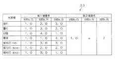
図4には、ROM33に記憶された本実施の形態に係る調整情報が一例として模式的に示されている。同図に示されるように、当該調整情報は、第1撮像系88Aに対応するテーブル及び第2撮像系88Bに対応するテーブルを備えており、各撮像系に対応するテーブルには、予め定められた複数の光源種(同図に示す例では、晴れ、曇り、日陰、電球、蛍光灯(白色)、蛍光灯(昼白色)及び蛍光灯(昼光色)。)と各光源種に応じたデジタルゲインとが関連付けされて記憶されている。 FIG. 4 schematically shows adjustment information according to the present embodiment stored in the
なお、各光源種に応じたデジタルゲインとしては、CCD14A又はCCD14Bの分光特性、各光源の色温度情報、各光源から照射される光の波長の分布等に基づいて、適正な色味を再現可能な値が適用されている。また、同図に示すように、本実施の形態では、感度の基準となるGの画像データのデジタルゲイン(WBa_G、WBb_G)をそれぞれ「1.0」で固定とし、これに対するRの画像データのデジタルゲイン(WBa_R、WBb_R)及びBの画像データのデジタルゲイン(WBa_B、WBb_B)がそれぞれ記憶されている。 As the digital gain corresponding to each light source type, appropriate color can be reproduced based on the spectral characteristics of the CCD 14A or CCD 14B, the color temperature information of each light source, the wavelength distribution of light emitted from each light source, and the like. The correct value is applied. Further, as shown in the figure, in the present embodiment, the digital gain (WBa_G, WBb_G) of the G image data serving as the sensitivity reference is fixed to “1.0”, and the R image data corresponding thereto is fixed. Digital gains (WBa_R, WBb_R) and digital gains (WBa_B, WBb_B) of B image data are stored.
次に、本実施の形態に係るデジタルカメラ10の作用を説明する。まず、立体撮影モードが設定されている場合のデジタルカメラ10の全体的な動作について説明する。 Next, the operation of the
まず、第1撮像系88Aにおいて、CCD14Aによる被写体像の光学ユニット13Aを介した撮像が行なわれ、被写体像を示す信号がCCD14AからCDS16Aに順次出力される。 First, in the first imaging system 88A, the subject image is picked up by the CCD 14A via the
CDS16Aは、CCD14Aから入力された信号に対して相関二重サンプリング処理を施し、これによって得られたR(赤)、G(緑)、B(青)のアナログ画像信号を順次ADC18Aに出力する。 The CDS 16A performs correlated double sampling processing on the signal input from the CCD 14A and sequentially outputs analog image signals of R (red), G (green), and B (blue) obtained thereby to the ADC 18A.
そして、ADC18Aは、CDS16Aから入力されたR、G、Bのアナログ画像信号を各々12ビットのR、G、B信号(デジタル画像データ)に変換して画像入力コントローラ20に出力する。 The ADC 18A converts the R, G, and B analog image signals input from the CDS 16A into 12-bit R, G, and B signals (digital image data) and outputs the converted signals to the
この第1撮像系88Aの動作に並行して、第2撮像系88Bにおいても、CCD14Bによる被写体像の光学ユニット13Bを介した撮像が行なわれて当該被写体像を示す信号がCCD14BからCDS16Bに順次出力され、CDS16Bにより、CCD14Bから入力された信号に対して相関二重サンプリング処理を施し、これによって得られたR、G、Bのアナログ画像信号を順次ADC18Bに出力し、ADC18Bは、CDS16Bから入力されたR、G、Bのアナログ画像信号を各々12ビットのR、G、B信号(デジタル画像データ)に変換して画像入力コントローラ20に出力する。 In parallel with the operation of the first image pickup system 88A, the second image pickup system 88B also picks up the subject image by the CCD 14B via the optical unit 13B, and sequentially outputs a signal indicating the subject image from the CCD 14B to the CDS 16B. The CDS 16B performs correlated double sampling processing on the signal input from the CCD 14B and sequentially outputs the R, G, B analog image signals to the
画像入力コントローラ20は内蔵しているラインバッファにADC18A及びADC18Bから順次入力される2画像分のデジタル画像データを蓄積して一旦第2メモリ40の所定領域に格納する。 The
第2メモリ40の所定領域に格納された2画像分のデジタル画像データは、CPU32による制御下で立体画像信号処理回路23によって読み出され、これらに上述した各種画像処理(図3参照)を施し、得られたYC信号を第2メモリ40の上記所定領域とは異なる領域に格納する。 Digital image data for two images stored in a predetermined area of the second memory 40 is read out by the stereoscopic image
なお、LCD30は、各撮像系による連続的な撮像によって得られた動画像(スルー画像)を表示してファインダとして使用することができるものとして構成されているが、このようにLCD30をファインダとして使用する場合には、第2メモリの所定領域に格納された立体画像を示すYC信号を、ビデオ/LCDエンコーダ28を介して順次LCD30に出力する。これによってLCD30にスルー画像が表示されることになる。 The
ここで、レリーズボタン52Aがユーザによって半押し状態とされたタイミングで、各撮像系において前述したようにAE機能が働いて露出状態が設定された後、AF機能が働いて合焦制御され、その後、引き続き全押し状態とされたタイミングで、その時点で第2メモリ40に格納されているYC信号を、圧縮・伸張処理回路24によって所定の圧縮形式(本実施の形態では、JPEG形式)で圧縮した後にメディアコントローラ42を介して記録メディア43に記録する。 Here, at the timing when the
なお、通常撮影モードが設定されている場合のデジタルカメラ10の動作は、立体画像信号処理回路23に代えて、画像信号処理回路22により、予め選択された撮像系によって得られたデジタル画像データのみに対して各種画像信号処理を施してYC信号を生成し、当該YC信号を第2メモリ40に格納する点を除いて、上述した立体撮影モードが設定されている場合の動作と略同様であるので、ここでの説明は省略する。 Note that the operation of the
ところで、デジタルカメラ10では、上記AE・AWB検出回路36により検出された物理量に基づいてホワイトバランス調整を行なうオートホワイトバランス機能と、ROM33に記憶された調整情報に基づいてホワイトバランス調整を行なうプリセットホワイトバランス機能と、の何れか一方をユーザによる操作部52の操作に応じて選択的に実行するようにしている。 By the way, in the
ユーザによりプリセットホワイトバランス機能が選択された場合及びプリセットホワイトバランス機能における光源種の選択状況が変更された場合、デジタルカメラ10では、立体画像信号処理回路23に対してホワイトバランス調整処理92を行なう際のゲインを設定するWBゲイン設定処理を実行する。 When the preset white balance function is selected by the user and the light source type selection status in the preset white balance function is changed, the
図5は、このときCPU32が実行するWBゲイン設定処理プログラムの処理の流れを示すフローチャートであり、以下、同図を参照して本実施の形態に係るWBゲイン設定処理について説明する。 FIG. 5 is a flowchart showing the flow of processing of the WB gain setting processing program executed by the
なお、ここでは、プリセットホワイトバランス機能が選択される際には、予め定められた複数の光源種の何れかが選択されるものとして説明する。 Here, it is assumed that when the preset white balance function is selected, one of a plurality of predetermined light source types is selected.
まず、ステップ100では、選択された光源種に応じたデジタルゲインをROM33の各撮像光学系に応じたテーブルからそれぞれ読み出す。 First, in
例えば、選択された光源種が「日陰」であった場合、第1撮像系88Aに対応するテーブルからWBa_G=1.0、WBa_R=4.0及びWBa_B=1.0をそれぞれ読み出すと共に、第2撮像系88Bに対応するテーブルからWBb_G=1.0、WBb_R=4.8及びWBb_B=0.8をそれぞれ読み出す。 For example, when the selected light source type is “shade”, WBa_G = 1.0, WBa_R = 4.0, and WBa_B = 1.0 are read from the table corresponding to the first imaging system 88A, and the second WBb_G = 1.0, WBb_R = 4.8, and WBb_B = 0.8 are read from the table corresponding to the imaging system 88B.
次のステップ102では、読み出したデジタルゲインを立体画像信号処理回路23に設定した後、本WBゲイン設定処理プログラムを終了する。 In the
これ以降、立体画像信号処理回路23では、CPU32により設定されたデジタルゲインのうち、処理対象となるデジタル画像データが取得された撮像系に応じたデジタルゲインを用いてホワイトバランス調整処理92を行なう。 Thereafter, the stereoscopic image
以上詳細に説明したように、本第1の実施の形態によれば、第1撮像系88A及び第2撮像系88Bにより各々互いに異なる位置から被写体像を示すデジタル画像データを取得し、取得された複数のデジタル画像データのホワイトバランス調整処理を、予め設定されたゲインを用いて行なうに際し、各々第1撮像系88A及び第2撮像系88Bと1対1で対応する情報であり、かつ対応する撮像系により取得されたデジタル画像データのホワイトバランス調整に用いる複数の調整情報を予めROM33に記憶しておき、各撮像系に対応する調整情報に基づいて各々の撮像系に対応するゲインを設定しているので、ホワイトバランス制御を高精度に行なうことができる。 As described above in detail, according to the first embodiment, digital image data indicating a subject image is acquired from different positions by the first imaging system 88A and the second imaging system 88B, and acquired. When white balance adjustment processing of a plurality of digital image data is performed using a preset gain, the information is one-to-one corresponding to the first imaging system 88A and the second imaging system 88B, and the corresponding imaging is performed. A plurality of adjustment information used for white balance adjustment of digital image data acquired by the system is stored in the
また、本第1の実施の形態によれば、複数の光源種に応じた調整情報を記憶しておき、CPU32は、操作部52の操作により選択された光源種に応じた調整情報に基づいてゲインを設定するようにしているので、各撮像系のゲインを複数の光源種に応じて設定することができ、光源の種類によって異なる色温度に応じたホワイトバランス調整が可能である。 Further, according to the first embodiment, adjustment information corresponding to a plurality of light source types is stored, and the
さらに、本第1の実施の形態によれば、調整情報を、複数の光源種と各光源種に応じたデジタルゲインとを関連付けたものとしているので、選択された光源種と関連付けされたデジタルゲインをそのまま設定すればよいので、ゲインの設定処理が容易かつ高速に行なえる。 Furthermore, according to the first embodiment, since the adjustment information is obtained by associating a plurality of light source types with digital gains corresponding to the respective light source types, the digital gain associated with the selected light source type. Therefore, the gain setting process can be performed easily and at high speed.
(第2の実施の形態)(Second Embodiment)
上記第1の実施の形態では、立体画像信号処理回路23に対するゲインの設定を行なうための調整情報として、第1撮像系88A及び第2撮像系88Bにそれぞれ対応すると共に、予め定められた複数の光源種と各光源種に応じたデジタルゲインとを関連付けた2つのテーブルをROM33に記憶しておく形態について説明したが、本第2の実施の形態では、第1撮像系88Aに対応する調整情報として、予め定められた複数の光源種と各光源種に応じたデジタルゲインとを関連付けたテーブルを記憶しておき、第2撮像系88Bに対応する調整情報として、当該第2撮像系88Bのデジタルゲインを第1撮像系88Aのデジタルゲインに基づいて導出するための係数を記憶しておく形態について説明する。 In the first embodiment, the adjustment information for setting the gain for the stereoscopic image
なお、本第2の実施の形態に係るデジタルカメラの構成は、上述した第1の実施の形態に係るデジタルカメラ10の構成(図1乃至図3参照)と同様であるので、ここでの説明を省略する。 The configuration of the digital camera according to the second embodiment is the same as the configuration of the
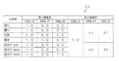
図6には、ROM33に記憶された本実施の形態に係る調整情報が一例として模式的に示されている。同図に示されるように、第1撮像系88Aに対応する調整情報として、予め定められた複数の光源種と各光源種に応じたデジタルゲインとを関連付けたテーブルが記憶されており、第2撮像系88Bに対応する調整情報として、当該第2撮像系88Bのデジタルゲインを第1撮像系88Aのデジタルゲインに基づいて導出するための係数が記憶されている。 In FIG. 6, the adjustment information according to the present embodiment stored in the
同図に示されるように、第1撮像系88Aに対応するテーブルには、予め定められた光源種(晴れ、曇り、日陰、電球、蛍光灯(白色)、蛍光灯(昼白色)、蛍光灯(昼光色))と各光源種に応じたデジタルゲインとが関連付けされて記憶されている。 As shown in the figure, the table corresponding to the first imaging system 88A includes predetermined light source types (sunny, cloudy, shade, light bulb, fluorescent light (white), fluorescent light (day white), fluorescent light. (Daylight color)) and a digital gain corresponding to each light source type are stored in association with each other.
なお、各光源種に応じたデジタルゲインとしては、CCD14Aの分光特性、各光源の色温度情報、各光源から照射される光の波長の分布等に基づいて、適正な色味を再現可能な値が適用されている。また、同図に示すように、本実施の形態では、感度の基準となるGの画像データのデジタルゲイン(WBa_G)を「1.0」で固定とし、これに対するRの画像データのデジタルゲイン(WBa_R)及びBの画像データのデジタルゲイン(WBa_B)がそれぞれ記憶されている。 The digital gain corresponding to each light source type is a value that can reproduce an appropriate color tone based on the spectral characteristics of the CCD 14A, the color temperature information of each light source, the wavelength distribution of light emitted from each light source, and the like. Has been applied. Also, as shown in the figure, in the present embodiment, the digital gain (WBa_G) of the G image data, which is a reference for sensitivity, is fixed at “1.0”, and the digital gain (R The digital gain (WBa_B) of the image data of WBa_R) and B is stored.
また、第2撮像系88Bのデジタルゲインを第1撮像系88Aのデジタルゲインに基づいて導出するための係数は、感度の基準となるWBb_Gについては1.0とし、係数α及び係数βは、製造ライン等において基準光源に対してGの値を1.0とし、R、G、Bのバランスを調整する際に得られた各撮像系のR、Bの値、各撮像系の分光特性の差等に基づくデータ及び実機を用いた実験やシミュレーション等により得られたデータに基づいて導出された係数を適用することができる。 In addition, the coefficient for deriving the digital gain of the second imaging system 88B based on the digital gain of the first imaging system 88A is 1.0 for WBb_G as a sensitivity reference, and the coefficients α and β are manufactured. Difference in R and B values of each imaging system and spectral characteristics of each imaging system obtained when adjusting the balance of R, G, and B with a G value of 1.0 with respect to a reference light source in a line or the like It is possible to apply coefficients derived on the basis of data based on the above and data obtained by experiments or simulations using actual machines.
次に、図7を参照して、本第2の実施の形態に係るWBゲイン設定処理について説明する。なお、図7は、ユーザによりプリセットホワイトバランス機能が選択された場合及びプリセットホワイトバランス機能における光源種の選択状況が変更された場合にCPU32が実行するWBゲイン設定処理プログラムの処理の流れを示すフローチャートである。 Next, a WB gain setting process according to the second embodiment will be described with reference to FIG. FIG. 7 is a flowchart showing the flow of processing of the WB gain setting processing program executed by the
なお、ここでは、プリセットホワイトバランス機能が選択される際には、予め定められた複数の光源種の何れかが選択されるものとして説明する。 Here, it is assumed that when the preset white balance function is selected, one of a plurality of predetermined light source types is selected.
まず、ステップ110では、係数及び選択された光源種に応じたデジタルゲインを読み出し、次のステップ112では、第2撮像系88Bのデジタルゲインを導出する。 First, in
例えば、選択された光源種が「日陰」であった場合、第1撮像系88Aに対応するテーブルからWBa_G=1.0、WBa_R=4.0及びWBa_B=1.0をそれぞれ読み出すと共に、第2撮像系88Bの調整情報(係数1.0、α及びβ)を読み出し、係数1.0、α及びβを選択された光源種に対応する第1撮像系88AのデジタルゲインWBa_G=1.0、WBa_R=4.0及びWBa_B=1.0にそれぞれ乗算し、第2撮像系88BのデジタルゲインWBb_G=1.0、WBb_R=α×4.0及びWBb_B=β×1.0を導出する。 For example, when the selected light source type is “shade”, WBa_G = 1.0, WBa_R = 4.0, and WBa_B = 1.0 are read from the table corresponding to the first imaging system 88A, and the second The adjustment information (coefficient 1.0, α and β) of the imaging system 88B is read, and the digital gain WBa_G = 1.0 of the first imaging system 88A corresponding to the selected light source type with the coefficients 1.0, α and β. By multiplying WBa_R = 4.0 and WBa_B = 1.0, respectively, the digital gain WBb_G = 1.0, WBb_R = α × 4.0, and WBb_B = β × 1.0 of the second imaging system 88B are derived.
次のステップ114では、各撮像系のデジタルゲインを立体画像信号処理回路23に設定した後、本WBゲイン設定処理プログラムを終了する。 In the
これ以降、立体画像信号処理回路23では、CPU32により設定されたデジタルゲインのうち、処理対象となるデジタル画像データが取得された撮像系に応じたデジタルゲインを用いてホワイトバランス調整処理92を行なう。 Thereafter, the stereoscopic image
以上詳細に説明したように、本第2の実施の形態によれば、第1撮像系88A及び第2撮像系88Bにより各々互いに異なる位置から被写体像を示すデジタル画像データを取得し、取得された複数のデジタル画像データのホワイトバランス調整処理を、予め設定されたゲインを用いて行なうに際し、各々第1撮像系88A及び第2撮像系88Bと1対1で対応する情報であり、かつ対応する撮像系により取得されたデジタル画像データのホワイトバランス調整に用いる複数の調整情報を予めROM33に記憶しておき、各撮像系に対応する調整情報に基づいて各々の撮像系に対応するゲインを設定しているので、ホワイトバランス制御を高精度に行なうことができる。 As described above in detail, according to the second embodiment, digital image data indicating a subject image is acquired from different positions by the first imaging system 88A and the second imaging system 88B, and acquired. When white balance adjustment processing of a plurality of digital image data is performed using a preset gain, the information is one-to-one corresponding to the first imaging system 88A and the second imaging system 88B, and the corresponding imaging is performed. A plurality of adjustment information used for white balance adjustment of digital image data acquired by the system is stored in the
また、本第2の実施の形態によれば、複数の光源種に応じた調整情報を記憶しておき、CPU32は、操作部52の操作により選択された光源種に応じた調整情報に基づいてゲインを設定するようにしているので、各撮像系のゲインを複数の光源種に応じて設定することができ、光源の種類によって異なる色温度に応じたホワイトバランス調整が可能である。 Further, according to the second embodiment, adjustment information corresponding to a plurality of light source types is stored, and the
さらに、本第2の実施の形態によれば、第1撮像系88Aに対応する調整情報を複数の光源種と各光源種に応じたデジタルゲインとを関連付けたものとし、第2撮像系88Bに対応する調整情報を第1撮像系88Aの各光源種に応じたデジタルゲインに基づいて当該第2撮像系88Bのデジタルゲインを導出するための係数とし、係数及び第1撮像系88Aの選択された光源種に応じたデジタルゲインに基づいて第2撮像系88Bのデジタルゲインを導出し、各撮像系のゲインをそれぞれ立体画像信号処理回路23に設定するようにしているので、第2撮像系88Bに対応する調整情報の情報容量を少なくすることができるので、ROM33の記憶容量を節約することができる。 Further, according to the second embodiment, adjustment information corresponding to the first imaging system 88A is associated with a plurality of light source types and digital gains corresponding to the respective light source types, and the second imaging system 88B The corresponding adjustment information is used as a coefficient for deriving the digital gain of the second imaging system 88B based on the digital gain corresponding to each light source type of the first imaging system 88A, and the coefficient and the first imaging system 88A are selected. Since the digital gain of the second imaging system 88B is derived based on the digital gain corresponding to the type of light source and the gain of each imaging system is set in the stereoscopic image
なお、本第2の実施の形態では、第2撮像系88Bの各画像データ(R、G、B)に対して1種類の係数を記憶しておく形態について説明したが、本発明はこれに限定されるものではなく、複数の係数を記憶しておくようにしてもよい。 In the second embodiment, a mode has been described in which one type of coefficient is stored for each image data (R, G, B) of the second imaging system 88B. The present invention is not limited, and a plurality of coefficients may be stored.
例えば、図8に示されるように、係数を、輝線を持たない光源種に応じた係数α1、β1及び輝線を持つ光源種に応じた係数α2、β2の2種類とし、選択された光源種の輝線の有無に応じた係数及び第1撮像系88Aの選択された光源種に応じたデジタルゲインに基づいて第2撮像系88Bのデジタルゲインを導出し、各撮像系のデジタルゲインを立体画像信号処理回路23に設定するようにすることもできる。これにより、ROM33の記憶容量を節約しつつ光源種の輝線の有無による色温度の極端な違いを考慮して、ホワイトバランス制御を高精度に行なうことができる。 For example, as shown in FIG. 8, the coefficients are set to two types of coefficients α1 and β1 according to the light source type having no bright line and coefficients α2 and β2 according to the light source type having the bright line, and the selected light source type is selected. The digital gain of the second imaging system 88B is derived based on the coefficient corresponding to the presence or absence of the bright line and the digital gain corresponding to the selected light source type of the first imaging system 88A, and the digital gain of each imaging system is subjected to stereoscopic image signal processing. The
(第3の実施の形態)(Third embodiment)
上記第1の実施の形態では、立体画像信号処理回路23に対するゲインの設定を行なうための調整情報として、第1撮像系88A及び第2撮像系88Bにそれぞれ対応すると共に、予め定められた複数の光源種と各光源種に応じたデジタルゲインとを関連付けた2つのテーブルをROM33に記憶しておく形態について説明したが、本第3の実施の形態では、第1撮像系88Aに対応する調整情報として、予め定められた複数の光源種と各光源種に応じたデジタルゲインとを関連付けたテーブルを記憶しておき、第2撮像系88Bに対応する調整情報として、所定の光源種に応じたデジタルゲインを当該光源種に関連付けて記憶しておく形態について説明する。 In the first embodiment, the adjustment information for setting the gain for the stereoscopic image
なお、本第3の実施の形態に係るデジタルカメラの構成は、上述した第1の実施の形態に係るデジタルカメラ10の構成(図1乃至図3参照)と同様であるので、ここでの説明を省略する。 The configuration of the digital camera according to the third embodiment is the same as the configuration of the
図9には、ROM33に記憶された本実施の形態に係る調整情報が一例として模式的に示されている。同図に示されるように、第1撮像系88Aに対応するテーブルでは、予め定められた光源種(晴れ、曇り、日陰、電球、蛍光灯(白色)、蛍光灯(昼白色)、蛍光灯(昼光色))と各光源種に応じたデジタルゲインとが関連付けされている。 FIG. 9 schematically shows the adjustment information according to the present embodiment stored in the
また、第2撮像系88Bについては、所定の光源種(晴れ)に応じたデジタルゲインのみが当該光源種と関連付けされている。 In the second imaging system 88B, only the digital gain corresponding to a predetermined light source type (clear) is associated with the light source type.
なお、各光源種に応じたデジタルゲインとしては、CCD14Aの分光特性、各光源の色温度情報、各光源から照射される光の波長の分布等に基づいて、適正な色味を再現可能な値が適用されている。また、同図に示すように、本実施の形態では、感度の基準となるGの画像データのデジタルゲイン(WBa_G)を「1.0」で固定とし、これに対するRの画像データのデジタルゲイン(WBa_R)及びBの画像データのデジタルゲイン(WBa_B)がそれぞれ記憶されている。 The digital gain corresponding to each light source type is a value that can reproduce an appropriate color tone based on the spectral characteristics of the CCD 14A, the color temperature information of each light source, the wavelength distribution of light emitted from each light source, and the like. Has been applied. Also, as shown in the figure, in the present embodiment, the digital gain (WBa_G) of the G image data, which is a reference for sensitivity, is fixed at “1.0”, and the digital gain (R The digital gain (WBa_B) of the image data of WBa_R) and B is stored.
次に、図10を参照して、本第2の実施の形態に係るWBゲイン設定処理について説明する。なお、図10は、ユーザによりプリセットホワイトバランス機能が選択された場合及びプリセットホワイトバランス機能における光源種の選択状況が変更された場合にCPU32が実行する、WBゲイン設定処理プログラムの処理の流れを示すフローチャートである。 Next, the WB gain setting process according to the second embodiment will be described with reference to FIG. FIG. 10 shows a flow of processing of the WB gain setting processing program executed by the
なお、ここでは、プリセットホワイトバランス機能が選択される際には、予め定められた複数の光源種の何れかが選択されるものとして説明する。 Here, it is assumed that when the preset white balance function is selected, one of a plurality of predetermined light source types is selected.
まず、ステップ120では、第1撮像系88A及び第2撮像系88Bの所定の光源種に応じたデジタルゲインを読み出し、次のステップ122では、選択された光源種が所定の光源種であるか否かを判定する。当該判定が肯定判定となった場合はステップ124に移行して読み出したデジタルゲインを立体画像信号処理回路23に設定した後、本WBゲイン設定処理プログラムを終了する。 First, in
一方、ステップ122で否定判定となった場合は、第2撮像系のデジタルゲインを導出する必要があると判断してステップ126に移行し、所定の光源種に応じたデジタルゲインを用いて、第1撮像系88Aのデジタルゲインと、第2撮像系88Bのデジタルゲインとの比率(WBb/WBa)を導出する。 On the other hand, if a negative determination is made in
すなわち、第1撮像系88Aに対応するテーブルからWBa_G=1.0、WBa_R=2.0及びWBa_B=3.0をそれぞれ読み出し、第2撮像系88Bに対応する調整情報WBb_G=1.0、WBb_R=2.4及びWBb_B=2.4を読み出して、G、R、Bのそれぞれについての比率として、 That is, WBa_G = 1.0, WBa_R = 2.0, and WBa_B = 3.0 are read from the table corresponding to the first imaging system 88A, respectively, and the adjustment information WBb_G = 1.0, WBb_R corresponding to the second imaging system 88B. = 2.4 and WBb_B = 2.4, and the ratio for each of G, R, and B
(WBb_G/WBa_G)=1.0(WBb_G / WBa_G) = 1.0
(WBb_R/WBa_R)=1.2(WBb_R / WBa_R) = 1.2
(WBb_B/WBa_B)=0.8(WBb_B / WBa_B) = 0.8
を導出する。Is derived.
次のステップ128では、第1撮像系88Aの選択された光源種に応じたデジタルゲインを読み出し、その後ステップ130に移行して、上記ステップ126で導出した比率と上記ステップ128で読み出した第1撮像系88Aの選択された光源種に応じたデジタルゲインとに基づいて第2撮像系88Bのデジタルゲインを導出する。 In the
例えば、選択された光源種が曇りであるとすると、第1撮像系88AのデジタルゲインとしてWBa_G=1.0、WBa_R=3.0及びWBa_B=2.0をそれぞれ読み出して、これらのデジタルゲインに導出された係数を乗算し、第2撮像系88Bのデジタルゲインとして、 For example, if the selected light source type is cloudy, WBa_G = 1.0, WBa_R = 3.0, and WBa_B = 2.0 are read as digital gains of the first imaging system 88A, and these digital gains are read. Multiplying the derived coefficient, as the digital gain of the second imaging system 88B,
WBb_G=1.0×1.0=1.0WBb_G = 1.0 × 1.0 = 1.0
WBb_R=3.0×1.2=3.6WBb_R = 3.0 × 1.2 = 3.6
WBb_B=2.0×0.8=1.6WBb_B = 2.0 × 0.8 = 1.6
を導出する。Is derived.
次のステップ132では、各撮像系のデジタルゲインを立体画像信号処理回路23に設定した後、本WBゲイン設定処理プログラムを終了する。 In the
これ以降、立体画像信号処理回路23では、CPU32により設定されたデジタルゲインのうち、処理対象となるデジタル画像データが取得された撮像系に応じたデジタルゲインを用いてホワイトバランス調整処理92を行なう。 Thereafter, the stereoscopic image
以上詳細に説明したように、本第3の実施の形態によれば、第1撮像系88A及び第2撮像系88Bにより各々互いに異なる位置から被写体像を示すデジタル画像データを取得し、取得された複数のデジタル画像データのホワイトバランス調整処理を、予め設定されたゲインを用いて行なうに際し、各々第1撮像系88A及び第2撮像系88Bと1対1で対応する情報であり、かつ対応する撮像系により取得されたデジタル画像データのホワイトバランス調整に用いる複数の調整情報を予めROM33に記憶しておき、各撮像系に対応する調整情報に基づいて各々の撮像系に対応するゲインを設定しているので、ホワイトバランス制御を高精度に行なうことができる。 As described above in detail, according to the third embodiment, digital image data indicating a subject image is acquired from different positions by the first imaging system 88A and the second imaging system 88B, and acquired. When white balance adjustment processing of a plurality of digital image data is performed using a preset gain, the information is one-to-one corresponding to the first imaging system 88A and the second imaging system 88B, and the corresponding imaging is performed. A plurality of adjustment information used for white balance adjustment of digital image data acquired by the system is stored in the
また、本第3の実施の形態によれば、複数の光源種に応じた調整情報を記憶しておき、CPU32は、操作部52の操作により選択された光源種に応じた調整情報に基づいてゲインを設定するようにしているので、各撮像系のゲインを複数の光源種に応じて設定することができ、光源の種類によって異なる色温度に応じたホワイトバランス調整が可能である。 Further, according to the third embodiment, adjustment information corresponding to a plurality of light source types is stored, and the
さらに、本第3の実施の形態によれば、第1撮像系88Aに対応する調整情報を複数の光源種と各光源種に応じたデジタルゲインとを関連付けたものとし、第2撮像系88Bに対応する調整情報を所定の光源種と当該光源種に応じたデジタルゲインとを関連付けたものとし、選択された光源種が所定の光源種以外の光源種であった場合には、第1撮像系88Aの所定の光源種に応じたデジタルゲインと第2撮像系88Bの所定の光源種に応じたデジタルゲインとの比率を導出し、当該比率及び第1撮像系88Aの選択された光源種に応じたデジタルゲインを用いて第2撮像系88Bのデジタルゲインを導出し、選択された光源種に応じた各撮像光学系のデジタルゲインを立体画像信号処理回路23に設定するようにしているので、選択情報により示される光源種が所定の光源種であった場合はデジタルゲインをそのまま設定すればよく、WBゲイン設定処理が容易かつ高速に行なえる一方、その他の光源種であった場合は第1撮像系88A及び第2撮像系88Bの所定の光源種に応じたデジタルゲインと、第1撮像系88Bの選択された光源種に応じたデジタルゲインとを用いて第2撮像系のデジタルゲインを導出するので、第2撮像系88Bに対応する調整情報の情報容量を少なくすることができ、ROM33の記憶容量を節約することができる。 Further, according to the third embodiment, the adjustment information corresponding to the first imaging system 88A is associated with a plurality of light source types and digital gains corresponding to the respective light source types, and the second imaging system 88B When the corresponding adjustment information is associated with a predetermined light source type and a digital gain corresponding to the light source type, and the selected light source type is a light source type other than the predetermined light source type, the first imaging system A ratio between the digital gain according to the predetermined light source type of 88A and the digital gain according to the predetermined light source type of the second imaging system 88B is derived, and according to the ratio and the selected light source type of the first imaging system 88A. The digital gain of the second imaging system 88B is derived using the digital gain obtained, and the digital gain of each imaging optical system corresponding to the selected light source type is set in the stereoscopic image
なお、所定の光源種としては、すべての光源種の基準となる光源種(図9における「晴れ」など)を適用することにより、適切な調整値を導出することができる。 As the predetermined light source type, an appropriate adjustment value can be derived by applying a light source type (such as “sunny” in FIG. 9) that serves as a reference for all light source types.
また、最もよく用いられると予測される光源等を適用することもでき、これにより最も使用される頻度の高い光源下において最も高精度にホワイトバランス調整を行うことができる。さらに、製造ライン等においてGの値を1.0とし、R、G、Bのバランスを調整する際に用いられる基準光源を適用することもできる。 Further, it is possible to apply a light source that is predicted to be used most frequently, and thereby, it is possible to perform white balance adjustment with the highest accuracy under a light source that is used most frequently. Furthermore, it is also possible to apply a reference light source used when adjusting the balance of R, G, and B by setting the value of G to 1.0 in a production line or the like.
なお、上記各実施の形態では、WBa_G及びWBb_Gの値を「1.0」で固定とする形態について説明したが、本発明はこれに限定されるものではなく、基準となる値については適宜変更可能であることは言うまでもない。 In each of the above embodiments, the description has been given of the mode in which the values of WBa_G and WBb_G are fixed at “1.0”. However, the present invention is not limited to this, and the reference value is appropriately changed. It goes without saying that it is possible.
また、WBa_G及びWBb_Gの値を固定とする場合、WBa_G及びWBb_Gのテーブルや係数に代えて固定値を記憶しておくようにしてもよいし、予め固定としたゲインについては、出荷時等の調整によりゲインを設定した後はゲインの設定を行なわないようにすることもできる。これにより、さらに調整情報の情報容量を少なくすることができる。 When the values of WBa_G and WBb_G are fixed, fixed values may be stored in place of the WBa_G and WBb_G tables and coefficients, and the gain fixed in advance is adjusted at the time of shipment. After setting the gain, it is possible not to set the gain. As a result, the information capacity of the adjustment information can be further reduced.
また、本実施の実施の形態で説明したフローチャート(図4及び図5参照)の処理の流れは一例であり、本発明の主旨を逸脱しない範囲内において適宜変更可能であることは言うまでもない。 Moreover, it is needless to say that the processing flow of the flowcharts (see FIGS. 4 and 5) described in the present embodiment is an example, and can be appropriately changed without departing from the gist of the present invention.
さらに、以上のデジタルカメラ10の構成(図1、図2参照)は一例であり、本発明の主旨を逸脱しない範囲内において適宜変更可能であることは言うまでもない。 Further, the above-described configuration of the digital camera 10 (see FIGS. 1 and 2) is an example, and it goes without saying that the configuration can be appropriately changed without departing from the gist of the present invention.
例えば、本実施の実施の形態では、光学ユニットを2系統備えた場合について説明したが、本発明はこれに限定されるものではなく、3系統以上の光学系ユニットを備えたカメラについても適用することができる。 For example, in this embodiment, the case where two optical units are provided has been described. However, the present invention is not limited to this, and the present invention is also applicable to a camera including three or more optical system units. be able to.
また、上記各実施の形態では、モード切換スイッチ52Bの操作によりデジタルカメラのモードが立体撮影モード、通常撮影モード及び再生モードの何れかが設定されるものとして説明したが、モード切換スイッチの操作によりデジタルカメラを撮影モード及び再生モードの何れかに設定するようにし、さらに立体画像を取扱う立体画像モードと通常の画像を取扱う通常画像モードの何れかを設定するためのスイッチを別途設けてもよい。このように構成した場合、デジタルカメラは、これらのスイッチの操作状態に応じて、立体画像撮影モード、通常画像撮影モード、立体画像再生モード及び通常画像再生モードの何れかのモードで動作することになる。 In each of the above embodiments, the mode of the digital camera has been described as being set to any one of the 3D shooting mode, the normal shooting mode, and the playback mode by operating the mode switch 52B. The digital camera may be set to either the shooting mode or the playback mode, and a switch for setting either a stereoscopic image mode for handling a stereoscopic image or a normal image mode for handling a normal image may be separately provided. In such a configuration, the digital camera operates in any one of the three-dimensional image shooting mode, the normal image shooting mode, the three-dimensional image reproduction mode, and the normal image reproduction mode according to the operation state of these switches. Become.
さらに、上記各実施の形態では、本発明をデジタルカメラに適用した場合について説明したが、本発明はデジタルカメラに限定されるものではなく、銀鉛写真フィルムを用いるカメラにも適用することもできる。 Further, in each of the above embodiments, the case where the present invention is applied to a digital camera has been described. However, the present invention is not limited to a digital camera, and can also be applied to a camera using a silver-lead photographic film. .
10 デジタルカメラ
23 立体画像信号処理回路(調整手段)
32 CPU(設定手段)
33 ROM(記憶手段)
88A 第1撮像系(撮像光学系)
88B 第2撮像系(撮像光学系)10
32 CPU (setting means)
33 ROM (storage means)
88A First imaging system (imaging optical system)
88B Second imaging system (imaging optical system)
Claims (2)
Translated fromJapanese予め定められた複数の光源種の何れかを選択する選択情報を入力するための入力手段と、
前記複数の光源種と、前記複数の撮像光学系により取得された複数の画像情報のホワイトバランス調整を行うために用いられる、各光源種に応じた調整値とを関連付けて予め記憶した記憶手段と、
前記入力手段から入力された選択情報によって示される光源種に応じた調整値を前記記憶手段から読み出して設定する設定手段と、
前記設定手段により設定された調整値を用いて前記ホワイトバランス調整を行なう調整手段と、
を備えたカメラ。A plurality of imaging optical systems for acquiring image information indicating subject images from different positions;
An input means for inputting selection information for selecting any one of a plurality of predetermined light source types;
A storage unit that stores the plurality of light source types in advance in association with adjustment values according to each light source type, which are used to perform white balance adjustment of a plurality of pieces of image information acquired by the plurality of imaging optical systems; ,
A setting unit that reads and sets an adjustment value corresponding to a light source type indicated by the selection information input from the input unit from the storage unit;
Adjusting means for performing the white balance adjustment using the adjustment value set by the setting means;
With a camera.
前記複数の光源種と、前記複数の撮像光学系により取得された複数の画像情報のホワイトバランス調整を行うために用いられる、各光源種に応じた調整値とを関連付けて予め記憶しておき、
前記入力手段から入力された選択情報によって示される光源種に応じた調整値を記憶した内容に基づいて設定し、
設定された調整値を用いて前記ホワイトバランス調整を行なう
カメラの制御方法。A plurality of imaging optical systems for acquiring image information indicating subject images from different positions, and an input means for inputting selection information for selecting any one of a plurality of predetermined light source types. Control method of the camera,
The plurality of light source types and the adjustment value according to each light source type used for white balance adjustment of a plurality of pieces of image information acquired by the plurality of imaging optical systems are associated and stored in advance.
Based on the stored stored adjustment value according to the light source type indicated by the selection information input from the input means,
A camera control method for performing the white balance adjustment using a set adjustment value.
Priority Applications (1)
| Application Number | Priority Date | Filing Date | Title |
|---|---|---|---|
| JP2008275679AJP2009065695A (en) | 2008-10-27 | 2008-10-27 | Camera and camera control method |
Applications Claiming Priority (1)
| Application Number | Priority Date | Filing Date | Title |
|---|---|---|---|
| JP2008275679AJP2009065695A (en) | 2008-10-27 | 2008-10-27 | Camera and camera control method |
Related Parent Applications (1)
| Application Number | Title | Priority Date | Filing Date |
|---|---|---|---|
| JP2004006830ADivisionJP4227030B2 (en) | 2004-01-14 | 2004-01-14 | Camera and camera control method |
Publications (1)
| Publication Number | Publication Date |
|---|---|
| JP2009065695Atrue JP2009065695A (en) | 2009-03-26 |
Family
ID=40559786
Family Applications (1)
| Application Number | Title | Priority Date | Filing Date |
|---|---|---|---|
| JP2008275679APendingJP2009065695A (en) | 2008-10-27 | 2008-10-27 | Camera and camera control method |
Country Status (1)
| Country | Link |
|---|---|
| JP (1) | JP2009065695A (en) |
Citations (3)
| Publication number | Priority date | Publication date | Assignee | Title |
|---|---|---|---|---|
| JPS62104389A (en)* | 1985-10-31 | 1987-05-14 | Nippon Tv Housoumou Kk | Color TV camera white balance adjustment method |
| JPH0795595A (en)* | 1993-09-21 | 1995-04-07 | Canon Inc | Color imaging device |
| JP2001136539A (en)* | 1999-11-04 | 2001-05-18 | Nikon Corp | Electronic camera |
- 2008
- 2008-10-27JPJP2008275679Apatent/JP2009065695A/enactivePending
Patent Citations (3)
| Publication number | Priority date | Publication date | Assignee | Title |
|---|---|---|---|---|
| JPS62104389A (en)* | 1985-10-31 | 1987-05-14 | Nippon Tv Housoumou Kk | Color TV camera white balance adjustment method |
| JPH0795595A (en)* | 1993-09-21 | 1995-04-07 | Canon Inc | Color imaging device |
| JP2001136539A (en)* | 1999-11-04 | 2001-05-18 | Nikon Corp | Electronic camera |
Similar Documents
| Publication | Publication Date | Title |
|---|---|---|
| JP4791331B2 (en) | Imaging apparatus and exposure control method | |
| US20110018970A1 (en) | Compound-eye imaging apparatus | |
| JP4588583B2 (en) | Imaging apparatus and focus control method | |
| US8284294B2 (en) | Compound-eye image pickup apparatus | |
| JP4153444B2 (en) | Digital camera | |
| US8687047B2 (en) | Compound-eye imaging apparatus | |
| JP2024122091A (en) | Information processing device and control method thereof | |
| JP2005311699A (en) | Imaging apparatus and display control method | |
| JP5458937B2 (en) | IMAGING DEVICE, IMAGING METHOD, AND COMPUTER-READABLE RECORDING MEDIUM CONTAINING PROGRAM FOR EXECUTING THE IMAGING METHOD | |
| CN104246597B (en) | Imaging device and formation method | |
| JP4796007B2 (en) | Imaging device | |
| JP2008109485A (en) | Imaging apparatus and imaging control method | |
| JP2008053931A (en) | Imaging device | |
| JP2005323162A (en) | Imaging apparatus and method for recording image | |
| JP5277863B2 (en) | Imaging apparatus and imaging method | |
| JP4136958B2 (en) | Digital camera and digital camera control method | |
| JP4227030B2 (en) | Camera and camera control method | |
| US8041206B2 (en) | Imaging apparatus and method for controlling flash emission | |
| JP2005202037A (en) | Stereo camera | |
| JP2011030091A (en) | Compound eye image pickup device and method for adjusting white balance of the same | |
| JP2008005248A (en) | Imaging device | |
| JP2006080960A (en) | Imaging apparatus and imaging method | |
| EP3276938B1 (en) | Imaging device | |
| JP2005039401A (en) | Camera and photographing method of stereoscopic image | |
| JP5927565B2 (en) | Imaging device |
Legal Events
| Date | Code | Title | Description |
|---|---|---|---|
| A131 | Notification of reasons for refusal | Free format text:JAPANESE INTERMEDIATE CODE: A131 Effective date:20111101 | |
| A521 | Request for written amendment filed | Free format text:JAPANESE INTERMEDIATE CODE: A523 Effective date:20111221 | |
| A02 | Decision of refusal | Free format text:JAPANESE INTERMEDIATE CODE: A02 Effective date:20120124 |