JP2009063371A - Encoder device and starting method thereof - Google Patents
Encoder device and starting method thereofDownload PDFInfo
- Publication number
- JP2009063371A JP2009063371AJP2007230496AJP2007230496AJP2009063371AJP 2009063371 AJP2009063371 AJP 2009063371AJP 2007230496 AJP2007230496 AJP 2007230496AJP 2007230496 AJP2007230496 AJP 2007230496AJP 2009063371 AJP2009063371 AJP 2009063371A
- Authority
- JP
- Japan
- Prior art keywords
- encoder
- motor
- parameter
- sum value
- parameters
- Prior art date
- Legal status (The legal status is an assumption and is not a legal conclusion. Google has not performed a legal analysis and makes no representation as to the accuracy of the status listed.)
- Pending
Links
Images


Landscapes
- Control Of Electric Motors In General (AREA)
- Transmission And Conversion Of Sensor Element Output (AREA)
Abstract
Description
Translated fromJapanese本発明は、各種エンコーダ装置に関するもので、特に、モータの回転を検出するセンサから出力されるエンコーダ信号の処理を行って上位コントローラに対してモータの回転数に応じた信号をフィードバックするエンコーダ装置およびその起動方法に関する。 The present invention relates to various encoder devices, and in particular, an encoder device that processes an encoder signal output from a sensor that detects rotation of a motor and feeds back a signal corresponding to the number of rotations of the motor to a host controller and It relates to the starting method.
モータの回転を検出するセンサから出力されるエンコーダ信号の処理を行って上位コントローラに対してモータの回転数に応じた信号をフィードバックするエンコーダ信号処理は従来より行なわれている。例えば、図5に示す回路ブロックは、特許文献1に開示されているもので、図5において、21はモータ10の制御を行うための上位コントローラであり、速度制御、位置制御等の処理を行うCPU22と、CPU22からの指令によりモータ10に対して必要なトルクを発生するための電流を供給するためのドライバ回路23と、ラインドライバ7とラインレシーバ8により構成されている。100はエンコーダ装置であり、モータ10の回転を検出するため軸に取り付けられたセンサから出力されるエンコーダ信号の処理を行い位置データを生成するためのCPU2、エンコーダ信号処理回路3、モータ10の駆動制御に必要なエンコーダのパルス数や極性などのエンコーダパラメータと、装着するモータの出力や誘起電圧定数、トルク定数などのモータパラメータが書き込まれたROM、もしくは、不揮発性のRAMなどの記憶装置4と、ラインドライバ7とラインレシーバ8により構成されている。
上位コントローラ21とエンコーダ装置100は伝送路により接続されており、エンコーダ装置100は上位コントローラ21に対してモータ10の回転数に対応した信号をフィードバックする。このように、従来のエンコーダ装置100は、上位コントローラ21に対してモータ10の回転数に応じた信号をフィードバックする。
The host controller 21 and the encoder device 100 are connected by a transmission path, and the encoder device 100 feeds back a signal corresponding to the rotational speed of the motor 10 to the host controller 21. Thus, the conventional encoder device 100 feeds back a signal corresponding to the number of rotations of the motor 10 to the host controller 21.
従来のエンコーダ装置100は、記憶装置4に書き込まれたモータ10の駆動制御に必要なエンコーダのパルス数や極性などのエンコーダパラメータと、装着するモータ10の出力や誘起電圧定数、トルク定数などのモータパラメータは、システム起動時にCPU2にて一旦読み出した後、エンコーダ信号処理回路3に対して設定データを書き込む必要があり、CPUの初期化に時間がかかるという問題があった。
本発明はこのような問題点に鑑みてなされたものであり、記憶装置に格納されたパラーメータ等の設定データを自動的に読み出し、エンコーダ信号処理回路に設定することにより、CPUの負荷を軽減し初期化時間を削減することができるエンコーダ装置およびその起動方法を提供することを目的とする。The conventional encoder device 100 includes encoder parameters such as the number of pulses and polarity of the encoder necessary for driving control of the motor 10 written in the
The present invention has been made in view of such problems, and automatically reads setting data such as parameters stored in a storage device and sets them in an encoder signal processing circuit, thereby reducing the load on the CPU. It is an object of the present invention to provide an encoder apparatus capable of reducing initialization time and a starting method thereof.
上記問題を解決するため、請求項1記載のエンコーダ装置の発明は、モータの回転を検出するセンサから出力されるエンコーダ信号の処理を行って上位コントローラに対してモータの回転数に応じた信号をフィードバックするエンコーダ信号処理回路と、前記モータのモータパラメータと前記モータの駆動制御に必要なエンコーダのエンコーダパラメータとが書き込まれた記憶装置と、前記エンコーダ信号処理回路と前記記憶装置に制御指令を出すCPUとを備えたエンコーダ装置であって、前記エンコーダ装置は制御信号生成回路を備え、該制御信号生成回路がシステムロード開始信号により前記記憶装置に格納された前記モータパラメータと前記エンコーダパラメータとを読み出し自動的に設定することを特徴としている。
請求項2記載の発明は、請求項1エンコーダ装置において、前記モータパラメータが、装着するモータの出力や誘起電圧定数、トルク定数を含むパラメータで、エンコーダパラメータがパルス数や極性を含むパラメータであることを特徴としている。
請求項3記載の発明は、請求項1又は2記載のエンコーダ装置において、前記エンコーダ装置がサム値の計算を行うサム値計算回路を備え、該サム値計算回路が前記制御信号生成回路動作時に自動的に設定する書き込みデータについてサム値の計算を行うことを特徴としている。
請求項4記載の発明は、請求項1〜3のいずれか1項記載のエンコーダ装置において、前記システムロード開始信号として、モータおよび上位コントローラを含むシステムのリセット信号を使用し、システム起動時に前記モータパラメータと前記エンコーダパラメータとを読み出し、自動的に設定することを特徴としている。
請求項5記載の発明は、請求項1〜3のいずれか1項記載のエンコーダ装置において、前記システムロード開始信号として、前記CPUの出力ポートを使用し、前記CPUにて任意のタイミングで前記モータパラメータと前記エンコーダパラメータとを読み出し、自動的に設定することを特徴としている。
請求項6記載の発明は、請求項1又は2記載のエンコーダ装置において、前記記憶装置が複数の領域に分けてモータパラメータとエンコーダパラメータが書き込まれており、前記制御信号生成回路はロード領域選択信号により選択された領域に格納されたパラメータのみを読み出し自動的に設定することを特徴としている。
請求項7記載の発明は、請求項3〜6のいずれか1項記載のエンコーダ装置において、前記サム値が、前記サム値確認の結果が一致しない場合は異常と判定し通知されることを特徴としている。
請求項8記載のエンコーダ装置の起動方法の発明は、モータの回転を検出するセンサから出力されるエンコーダ信号の処理をして上位コントローラに対してモータの回転数に応じた信号をフィードバックするエンコーダ信号処理回路を備えたエンコーダ装置を起動するに際し、システムロード開始信号により、前記モータのモータパラメータと前記エンコーダパラメータとが書き込まれた記憶装置から選択されたモータパラメータとエンコーダパラメータとを読み出し自動的に設定するようにしたことを特徴としている。
請求項9記載の発明は、請求項8記載のエンコーダ装置の起動方法において、前記制御信号生成回路の動作時に自動的に設定する書き込みデータについてサム値の計算を行ない、前記サム値が前記サム値確認の結果が一致しない場合は異常と判定することを特徴としている。In order to solve the above problem, the encoder device according to the first aspect of the present invention processes the encoder signal output from the sensor that detects the rotation of the motor, and outputs a signal corresponding to the number of rotations of the motor to the host controller. An encoder signal processing circuit for feedback, a storage device in which motor parameters of the motor and encoder parameters of the encoder necessary for driving control of the motor are written, and a CPU that issues control commands to the encoder signal processing circuit and the storage device The encoder device includes a control signal generation circuit, and the control signal generation circuit automatically reads out the motor parameter and the encoder parameter stored in the storage device in response to a system load start signal. It is characterized by setting it automatically.
The invention according to
According to a third aspect of the present invention, in the encoder device according to the first or second aspect, the encoder device includes a sum value calculation circuit for calculating a sum value, and the sum value calculation circuit is automatically operated when the control signal generation circuit operates. It is characterized in that a sum value is calculated for write data to be set automatically.
According to a fourth aspect of the present invention, in the encoder device according to any one of the first to third aspects, a system reset signal including a motor and a host controller is used as the system load start signal. The parameters and the encoder parameters are read out and automatically set.
According to a fifth aspect of the present invention, in the encoder device according to any one of the first to third aspects, an output port of the CPU is used as the system load start signal, and the motor is at an arbitrary timing in the CPU. The parameters and the encoder parameters are read out and automatically set.
According to a sixth aspect of the present invention, in the encoder device according to the first or second aspect, the storage device is divided into a plurality of areas in which motor parameters and encoder parameters are written, and the control signal generation circuit receives a load area selection signal. Only the parameters stored in the area selected by the above are read and set automatically.
According to a seventh aspect of the present invention, in the encoder device according to any one of the third to sixth aspects, when the sum value does not match the result of the sum value confirmation, it is determined that there is an abnormality and is notified. It is said.
The invention of the start method of the encoder device according to claim 8 is an encoder signal for processing an encoder signal output from a sensor for detecting rotation of a motor and feeding back a signal corresponding to the number of rotations of the motor to a host controller. When starting an encoder device equipped with a processing circuit, the motor load and encoder parameters selected from the storage device in which the motor parameters and encoder parameters of the motor are written are automatically set by a system load start signal. It is characterized by doing so.
According to a ninth aspect of the present invention, in the method of starting an encoder device according to the eighth aspect, a sum value is calculated for write data that is automatically set when the control signal generating circuit operates, and the sum value is the sum value. If the result of confirmation does not match, it is characterized in that it is determined as abnormal.
請求項1に記載の発明によると、制御信号生成回路により記憶装置に格納されたエンコーダのパルス数、極性などのエンコーダパラメータと、装着するモータの出力や誘起電圧定数、トルク定数などのモータパラメータを自動的に読み出し設定を行うことにより、従来システム起動時にCPUが行っていた初期化処理を省き、初期化の時間を削減すると共にCPUの処理を軽減することができる。
請求項2に記載の発明によると、モータパラメータが、装着するモータの出力や誘起電圧定数、トルク定数を含むパラメータで、エンコーダパラメータがパルス数や極性を含むパラメータとすることで、従来システム起動時にCPUが行っていた初期化処理を省き、初期化の時間を削減すると共にCPUの処理を軽減することができる。
請求項3に記載の発明によると、制御信号生成回路動作中に設定データのサム値を計算することにより、誤った設定データが書き込まれた場合にはチェックサム異常を検出することができ、エンコーダ装置の信頼性を向上することができる。
また、請求項4記載の発明によると、システムロード開始信号にシステムのリセット信号を使用することにより、システム起動時に記憶装置に格納されたエンコーダのパルス数や極性などのエンコーダパラメータと、装着するモータの出力や誘起電圧定数、トルク定数などのモータパラメータを読み出し自動的に設定することができ、従来システム起動時にCPUが行っていた初期化処理を省き、初期化の時間を削減すると共にCPUの処理を軽減することができる。
また、請求項5記載の発明によると、システムロード開始信号にCPUの出力ポートを使用することにより、任意のタイミングで記憶装置に格納されたエンコーダのパルス数や極性などのエンコーダパラメータと、装着するモータの出力や誘起電圧定数、トルク定数などのモータパラメータを読み出し自動的に設定することができ、従来システム起動時にCPUが行っていた初期化処理を省き、初期化の時間を削減すると共にCPUの処理を軽減することができる。
また、請求項6記載の発明によると、ロード領域選択信号により選択された領域に書き込まれたパラメータのみを自動的に設定することにより、必要なパラメータのみを自動的に設定を行うことができ、初期化の時間を削減することができる。
また、請求項7記載の発明によると、サム値確認の結果が一致しない場合は異常と判定するので、常に正確なパラメータの設定が可能となる。
また、請求項8に記載の発明によると、従来システム起動時にCPUが行っていた初期化処理を省き、初期化の時間を削減すると共にCPUの処理を軽減することができる。
そして、請求項9に記載の発明によると、誤った設定データが書き込まれた場合にはチェックサム異常を検出することができ、エンコーダ装置の信頼性を向上することができる。According to the first aspect of the invention, the encoder parameters such as the number of pulses and polarity of the encoder stored in the storage device by the control signal generation circuit, and the motor parameters such as the output of the motor to be mounted, the induced voltage constant, and the torque constant By performing the read setting automatically, it is possible to omit the initialization process that has been performed by the CPU at the time of starting the system, thereby reducing the initialization time and reducing the CPU process.
According to the second aspect of the present invention, the motor parameter is a parameter including the output of the motor to be mounted, the induced voltage constant, and the torque constant, and the encoder parameter is a parameter including the number of pulses and the polarity. By omitting the initialization process performed by the CPU, the initialization time can be reduced and the CPU process can be reduced.
According to the invention described in
According to a fourth aspect of the invention, by using a system reset signal as a system load start signal, encoder parameters such as the number and polarity of encoder pulses stored in a storage device at the time of system startup, and a motor to be mounted Motor parameters such as output, induced voltage constant, torque constant, etc. can be read and set automatically, eliminating the initialization process that the CPU had done at the time of system startup, reducing the initialization time and CPU processing. Can be reduced.
According to the fifth aspect of the present invention, by using the CPU output port for the system load start signal, the encoder parameters such as the number of pulses and polarity of the encoder stored in the storage device can be mounted at an arbitrary timing. Motor parameters such as motor output, induced voltage constants, and torque constants can be read and set automatically, eliminating the initialization process that the CPU had done at the time of system startup and reducing the initialization time. Processing can be reduced.
According to the invention of
According to the seventh aspect of the present invention, if the result of the sum value confirmation does not match, it is determined that there is an abnormality, so that it is always possible to set an accurate parameter.
According to the eighth aspect of the present invention, it is possible to omit the initialization process that has been performed by the CPU at the time of system startup, thereby reducing the initialization time and reducing the CPU process.
According to the ninth aspect of the present invention, when erroneous setting data is written, a checksum abnormality can be detected, and the reliability of the encoder device can be improved.
以下、本発明の実施の形態について図を参照して説明する。 Hereinafter, embodiments of the present invention will be described with reference to the drawings.
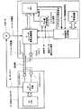
図1は本発明の実施例1に係るエンコーダ装置1のブロック図である。
図1において、CPU2、エンコーダ信号処理回路3、記憶装置4、ラインドライバ7、ラインレシーバ8、モータ10、上位コントローラ21、CPU22、ドライバ回路23は従来技術の図5と同一であるので、ここでは説明を省略する。
本発明により設けられた新たな構成としては、5の制御信号生成回路と、6のサム値計算回路である。制御信号生成回路5は記憶装置4からパラメータを読出し自動的に設定するものであり、サム値計算回路6は記憶装置4から読出したデータの誤り訂正処理を行うものである。FIG. 1 is a block diagram of an
In FIG. 1, the
The new configuration provided by the present invention includes 5 control signal generation circuits and 6 sum value calculation circuits. The control
次に、本発明の実施例1の動作について説明する。
先ず、システムロード開始信号が入力されると、制御信号生成回路5は、記憶装置4からモータパラメータとエンコーダパラメータを読み出しエンコーダ処理回路3に対して設定データと設定データ書き込み信号を出力し、データの設定を行う。なお、記憶装置4にはあらかじめ複数のロード領域に分けて、それぞれのロード領域にモータパラメータとエンコーダパラメータが書き込まれており、制御信号生成回路5はロード領域選択信号により選択された領域に格納されたモータパラメータとエンコーダパラメータのみを読み出し自動的に設定を行う。図4は以上のことを図示する記憶装置4のメモリマップ図である。図4に示す記憶装置4のメモリマップの例のように、記憶装置4はロード領域1〜NのN個のロード領域に分割されており、ロード領域選択信号によりロード領域1からロード領域Nまでのうちの1つのロード領域が選択される。各ロード領域1〜Nにはそれぞれモータパラメータとエンコーダパラメータが格納されており、たとえばモータの種別ごとに異なるものになっている。そこで、使用するモータによってロード領域選択信号によりモータパラメータとエンコーダパラメータを選択することでパラメータの設定ができ、このためエンコーダ装置としては共通化を図ることができる。
サム値計算回路6は制御信号生成回路5から出力される設定データ書き込み信号入力時の設定データに対してサム値の計算を行い、サム値をCPU2に対して出力する。この場合のサム値計算処理は、例えば、チェックサム方式によりデータの合計値(サム値)を計算しておき、これと読み出したデータの合計値との一致を検査するもので、サム値が一致しなければデータを廃棄し異常として処理する。
また、制御信号生成回路5はエンコーダ信号処理回路3に対するデータの設定完了時CPU2に対してシステムロード完了信号を出力しデータの設定完了を通知する。
このように、制御信号生成回路5にて自動的に記憶装置4から設定用パラメータを読み出しエンコーダ信号処理回路3に対して設定データと設定データ書き込み信号を出力しデータの設定を行うことにより、従来システム起動時にCPUが行っていた初期化処理を省き、初期化の時間を削減すると共にCPUの処理を軽減することができる。
また、CPU2はシステムロード完了信号時にサム値計算回路6から出力されるサム値の値を確認することで、エンコーダ信号処理回路3に誤った設定データが書き込まれた場合には異常を検出することができ、エンコーダ装置の信頼性を向上することができる。
本発明が図5に示した従来技術と異なる部分は、2つあり、図1で太線で示したように、1つはシステムロード開始信号により自動的に記憶装置4からパラメータ等の設定データを読み出しエンコーダ信号処理回路にデータの設定を行う制御信号生成回路5を設けたこと、2つ目は制御信号生成回路5の動作時に、エンコーダ信号処理回路3に誤った設定データが書き込まれた場合に異常を検出することができるデータのサム値計算回路6を備えたことである。Next, the operation of the first embodiment of the present invention will be described.
First, when a system load start signal is input, the control
The sum
The control
As described above, the control
Further, the
There are two parts of the present invention that are different from the prior art shown in FIG. 5. As shown by the thick line in FIG. 1, one of them automatically receives setting data such as parameters from the
次に、本発明の実施例2について説明する。
図2は本発明の実施例2に係るエンコーダ装置1’のブロック図である。
図2において、CPU2、エンコーダ信号処理回路3、記憶装置4、ラインドライバ7,ラインレシーバ8、モータ10,上位コントローラ21、CPU22、ドライバ回路23および制御信号発生回路5、サム値計算回路6は実施例1の図1とは同一構成であり、重複する説明は省略する。
図2のブロック図が図1のそれと異なる点は、太線で示すリセットIC9が追加された点である。
次に、実施例2の動作について説明する。
エンコーダ装置1’上のリセットIC9が出力するリセット信号をシステムロード開始信号とすることにより、システム起動時に制御信号生成回路5にて自動的に記憶装置4から前記パラメータを読み出しエンコーダ信号処理回路3に対して設定データと設定データ書き込み信号を出力しデータの設定を行うことができる。Next, a second embodiment of the present invention will be described.
FIG. 2 is a block diagram of an
In FIG. 2, the
The block diagram of FIG. 2 is different from that of FIG. 1 in that a
Next, the operation of the second embodiment will be described.
By using the reset signal output from the
次に、本発明の実施例3について説明する。
図3は本発明の実施例3に係るエンコーダ装置1”のブロック図である。
図3において、CPU2、エンコーダ信号処理回路3、記憶装置4、ラインドライバ7,ラインレシーバ8、モータ10,上位コントローラ21、CPU22、ドライバ回路23および制御信号発生回路5、サム値計算回路6は実施例2の図2とは同一構成であり、重複する説明は省略する。
図3のブロック図が図2のそれと異なる点は、リセットIC9の代わりに、太線で示すCPU2の出力ポートを用いた構成である。
次に、実施例3の動作について説明する。
エンコーダ装置1”上のCPU2の出力ポートををシステムロード開始信号とすることにより、任意のタイミングにて制御信号生成回路5にて自動的に記憶装置4から設定用パラメータを読み出しエンコーダ信号処理回路3に対して設定データと設定データ書き込み信号を出力しデータの設定を行うことができる。Next,
FIG. 3 is a block diagram of an
3, the
The block diagram of FIG. 3 is different from that of FIG. 2 in that the output port of the
Next, the operation of the third embodiment will be described.
By using the output port of the
1 本発明の実施例1に係るエンコーダ装置
1’本発明の実施例2に係るエンコーダ装置
1”本発明の実施例3に係るエンコーダ装置
2 CPU
3 エンコーダ信号処理回路
4 記憶装置
5 制御信号生成回路
6 サム値計算回路
7 ラインドライバ
8 ラインレシーバ
9 リセットIC
10 モータ
21 上位コントローラ
22 CPU
23 ドライバ回路DESCRIPTION OF
3 Encoder
10 Motor 21
23 Driver circuit
Claims (9)
Translated fromJapanese前記エンコーダ装置は制御信号生成回路を備え、該制御信号生成回路がシステムロード開始信号により前記記憶装置に格納された前記モータパラメータと前記エンコーダパラメータとを読み出し自動的に設定することを特徴とするエンコーダ装置。An encoder signal processing circuit that processes an encoder signal output from a sensor that detects the rotation of the motor and feeds back a signal corresponding to the number of rotations of the motor to the host controller, motor parameters of the motor, and driving of the motor An encoder device comprising: a storage device in which encoder parameters of an encoder necessary for control are written; a CPU that issues a control command to the encoder signal processing circuit and the storage device;
The encoder device includes a control signal generation circuit, and the control signal generation circuit reads and automatically sets the motor parameter and the encoder parameter stored in the storage device in response to a system load start signal. apparatus.
Priority Applications (1)
| Application Number | Priority Date | Filing Date | Title |
|---|---|---|---|
| JP2007230496AJP2009063371A (en) | 2007-09-05 | 2007-09-05 | Encoder device and starting method thereof |
Applications Claiming Priority (1)
| Application Number | Priority Date | Filing Date | Title |
|---|---|---|---|
| JP2007230496AJP2009063371A (en) | 2007-09-05 | 2007-09-05 | Encoder device and starting method thereof |
Publications (1)
| Publication Number | Publication Date |
|---|---|
| JP2009063371Atrue JP2009063371A (en) | 2009-03-26 |
Family
ID=40558077
Family Applications (1)
| Application Number | Title | Priority Date | Filing Date |
|---|---|---|---|
| JP2007230496APendingJP2009063371A (en) | 2007-09-05 | 2007-09-05 | Encoder device and starting method thereof |
Country Status (1)
| Country | Link |
|---|---|
| JP (1) | JP2009063371A (en) |
Cited By (2)
| Publication number | Priority date | Publication date | Assignee | Title |
|---|---|---|---|---|
| CN112213636A (en)* | 2020-09-30 | 2021-01-12 | 喻立陶 | Motor parameter self-memory and self-calibration method |
| CN113466688A (en)* | 2020-03-31 | 2021-10-01 | 北京配天技术有限公司 | Motor parameter identification method, device, motor, system and storage medium |
- 2007
- 2007-09-05JPJP2007230496Apatent/JP2009063371A/enactivePending
Cited By (2)
| Publication number | Priority date | Publication date | Assignee | Title |
|---|---|---|---|---|
| CN113466688A (en)* | 2020-03-31 | 2021-10-01 | 北京配天技术有限公司 | Motor parameter identification method, device, motor, system and storage medium |
| CN112213636A (en)* | 2020-09-30 | 2021-01-12 | 喻立陶 | Motor parameter self-memory and self-calibration method |
Similar Documents
| Publication | Publication Date | Title |
|---|---|---|
| CN110116752B (en) | Apparatus and method for controlling vehicle based on redundant structure | |
| JP5164030B2 (en) | Multi-axis motor drive system and multi-axis motor drive apparatus | |
| CN105980214B (en) | Control device and control method for in-vehicle electronic equipment | |
| JP6098581B2 (en) | Motor control device and electric power steering device using the same | |
| JP2013159120A (en) | Electronic control device and electric power steering device using the same | |
| JP2009063371A (en) | Encoder device and starting method thereof | |
| CN108860312B (en) | Method for calibrating a steering angle sensing device of a motor vehicle | |
| JP2011020544A (en) | Memory diagnostic device of control device of in-vehicle equipment | |
| WO2025148401A1 (en) | Gear shifting protection mechanism activation method, apparatus, and device, and storage medium | |
| CN113495606A (en) | Power manager circuit and electronic device for detecting internal errors | |
| JP6611877B1 (en) | Semiconductor integrated circuit and rotation detection device | |
| JP6945944B2 (en) | Rotation detector | |
| JP5975015B2 (en) | Electronic control device and electric power steering device using the same | |
| JP5494430B2 (en) | Information processing apparatus, motor driving apparatus using the same, and information processing method | |
| KR101531340B1 (en) | Servo motor control system | |
| EP3647742B1 (en) | Power supply circuit and motor control device | |
| JP4732091B2 (en) | Timing controller and image display device | |
| WO2022041100A1 (en) | Motor correction system | |
| JP4935241B2 (en) | Data holding device, motor control device and motor control system | |
| JP5273582B2 (en) | Servo motor control method | |
| JP6057860B2 (en) | Vehicle diagnostic device | |
| JP6324585B1 (en) | Engine start control device and start control method | |
| CN114123885A (en) | Calibration system for motor | |
| JP2024014035A (en) | sensor device | |
| CN120117030A (en) | A method, device and vehicle for aligning steering angles of a steering wheel and a steering wheel end |