JP2009061290A - Medical instrument manipulator - Google Patents
Medical instrument manipulatorDownload PDFInfo
- Publication number
- JP2009061290A JP2009061290AJP2008275653AJP2008275653AJP2009061290AJP 2009061290 AJP2009061290 AJP 2009061290AJP 2008275653 AJP2008275653 AJP 2008275653AJP 2008275653 AJP2008275653 AJP 2008275653AJP 2009061290 AJP2009061290 AJP 2009061290A
- Authority
- JP
- Japan
- Prior art keywords
- actuator
- catheter
- movement
- controller
- user
- Prior art date
- Legal status (The legal status is an assumption and is not a legal conclusion. Google has not performed a legal analysis and makes no representation as to the accuracy of the status listed.)
- Pending
Links
- 230000004044responseEffects0.000claimsabstractdescription38
- 239000012530fluidSubstances0.000claimsdescription23
- 238000000034methodMethods0.000claimsdescription18
- 206010044565TremorDiseases0.000claimsdescription8
- 238000003780insertionMethods0.000description8
- 230000037431insertionEffects0.000description8
- 210000001367arteryAnatomy0.000description6
- 210000004204blood vesselAnatomy0.000description6
- 238000004891communicationMethods0.000description6
- 230000000712assemblyEffects0.000description5
- 238000000429assemblyMethods0.000description5
- 230000008901benefitEffects0.000description4
- 230000008878couplingEffects0.000description4
- 238000010168coupling processMethods0.000description4
- 238000005859coupling reactionMethods0.000description4
- 239000000243solutionSubstances0.000description4
- 238000002399angioplastyMethods0.000description3
- 238000010586diagramMethods0.000description3
- 238000001356surgical procedureMethods0.000description3
- 230000000007visual effectEffects0.000description3
- 210000000683abdominal cavityAnatomy0.000description2
- 230000000747cardiac effectEffects0.000description2
- 230000000694effectsEffects0.000description2
- 238000001914filtrationMethods0.000description2
- 238000011010flushing procedureMethods0.000description2
- 238000003384imaging methodMethods0.000description2
- 238000002347injectionMethods0.000description2
- 239000007924injectionSubstances0.000description2
- 238000002697interventional radiologyMethods0.000description2
- 210000005259peripheral bloodAnatomy0.000description2
- 239000011886peripheral bloodSubstances0.000description2
- 230000002093peripheral effectEffects0.000description2
- 230000009467reductionEffects0.000description2
- 230000002792vascularEffects0.000description2
- 229910000831SteelInorganic materials0.000description1
- 208000007536ThrombosisDiseases0.000description1
- 210000002376aorta thoracicAnatomy0.000description1
- 230000002238attenuated effectEffects0.000description1
- 230000008859changeEffects0.000description1
- 238000007796conventional methodMethods0.000description1
- 238000003745diagnosisMethods0.000description1
- 230000010339dilationEffects0.000description1
- 210000001105femoral arteryAnatomy0.000description1
- 208000015181infectious diseaseDiseases0.000description1
- 230000003993interactionEffects0.000description1
- 230000002452interceptive effectEffects0.000description1
- 230000007246mechanismEffects0.000description1
- 230000000116mitigating effectEffects0.000description1
- 230000000737periodic effectEffects0.000description1
- 230000035945sensitivityEffects0.000description1
- 230000001953sensory effectEffects0.000description1
- 239000010959steelSubstances0.000description1
- 230000001960triggered effectEffects0.000description1
Images


Classifications
- A—HUMAN NECESSITIES
- A61—MEDICAL OR VETERINARY SCIENCE; HYGIENE
- A61B—DIAGNOSIS; SURGERY; IDENTIFICATION
- A61B34/00—Computer-aided surgery; Manipulators or robots specially adapted for use in surgery
- A61B34/70—Manipulators specially adapted for use in surgery
- A61B34/75—Manipulators having means for prevention or compensation of hand tremors
- A—HUMAN NECESSITIES
- A61—MEDICAL OR VETERINARY SCIENCE; HYGIENE
- A61B—DIAGNOSIS; SURGERY; IDENTIFICATION
- A61B34/00—Computer-aided surgery; Manipulators or robots specially adapted for use in surgery
- A61B34/70—Manipulators specially adapted for use in surgery
- A—HUMAN NECESSITIES
- A61—MEDICAL OR VETERINARY SCIENCE; HYGIENE
- A61B—DIAGNOSIS; SURGERY; IDENTIFICATION
- A61B34/00—Computer-aided surgery; Manipulators or robots specially adapted for use in surgery
- A61B34/70—Manipulators specially adapted for use in surgery
- A61B34/74—Manipulators with manual electric input means
- A—HUMAN NECESSITIES
- A61—MEDICAL OR VETERINARY SCIENCE; HYGIENE
- A61B—DIAGNOSIS; SURGERY; IDENTIFICATION
- A61B34/00—Computer-aided surgery; Manipulators or robots specially adapted for use in surgery
- A61B34/70—Manipulators specially adapted for use in surgery
- A61B34/76—Manipulators having means for providing feel, e.g. force or tactile feedback
- A—HUMAN NECESSITIES
- A61—MEDICAL OR VETERINARY SCIENCE; HYGIENE
- A61B—DIAGNOSIS; SURGERY; IDENTIFICATION
- A61B34/00—Computer-aided surgery; Manipulators or robots specially adapted for use in surgery
- A61B34/70—Manipulators specially adapted for use in surgery
- A61B34/77—Manipulators with motion or force scaling
- A—HUMAN NECESSITIES
- A61—MEDICAL OR VETERINARY SCIENCE; HYGIENE
- A61B—DIAGNOSIS; SURGERY; IDENTIFICATION
- A61B34/00—Computer-aided surgery; Manipulators or robots specially adapted for use in surgery
- A61B34/30—Surgical robots
- A61B2034/301—Surgical robots for introducing or steering flexible instruments inserted into the body, e.g. catheters or endoscopes
- A—HUMAN NECESSITIES
- A61—MEDICAL OR VETERINARY SCIENCE; HYGIENE
- A61M—DEVICES FOR INTRODUCING MEDIA INTO, OR ONTO, THE BODY; DEVICES FOR TRANSDUCING BODY MEDIA OR FOR TAKING MEDIA FROM THE BODY; DEVICES FOR PRODUCING OR ENDING SLEEP OR STUPOR
- A61M25/00—Catheters; Hollow probes
- A61M25/01—Introducing, guiding, advancing, emplacing or holding catheters
- A61M25/0105—Steering means as part of the catheter or advancing means; Markers for positioning
Landscapes
- Health & Medical Sciences (AREA)
- Surgery (AREA)
- Engineering & Computer Science (AREA)
- Life Sciences & Earth Sciences (AREA)
- Medical Informatics (AREA)
- Robotics (AREA)
- Biomedical Technology (AREA)
- Heart & Thoracic Surgery (AREA)
- Nuclear Medicine, Radiotherapy & Molecular Imaging (AREA)
- Molecular Biology (AREA)
- Animal Behavior & Ethology (AREA)
- General Health & Medical Sciences (AREA)
- Public Health (AREA)
- Veterinary Medicine (AREA)
- Media Introduction/Drainage Providing Device (AREA)
- Manipulator (AREA)
- Endoscopes (AREA)
Abstract
Description
Translated fromJapanese本発明は、使用者が対象物を操作することを可能にし、使用者に触覚または触覚的フィードバックを与える主従制御システムの分野に関し、より詳細には、外科処置に使用される主従システムに関する。 The present invention relates to the field of master-slave control systems that allow a user to manipulate an object and provide tactile or tactile feedback to the user, and more particularly to a master-slave system used in a surgical procedure.
「微小侵襲(minimally-invasive)」の外科手法の使用が増加する傾向にある。この手法は、医療器具が皮膚の比較的小さい穴を通して患者の身体へ挿入され、身体の外部から操作される手法を意味する。バルーン血管形成術として知られている微小侵襲外科手法の一例において、同心カテーテルが患者の身体へ挿入され、詰まりの生じている心臓動脈または抹消血管などの狭い血管へ誘導される。そして、端部の近くにバルーン状膨張室を有することから「バルーンカテーテル」と呼ばれているカテーテルの一つが血管へ誘導される。バルーン状の膨張室が膨張して閉鎖領域にある血管を伸長し、狭い流路を拡張する。 There is a growing trend to use “minimally-invasive” surgical techniques. This means a technique in which a medical device is inserted into a patient's body through a relatively small hole in the skin and operated from outside the body. In one example of a microinvasive surgical procedure known as balloon angioplasty, a concentric catheter is inserted into a patient's body and guided into a narrow vessel such as a clogged heart artery or peripheral blood vessel. And since it has a balloon-like expansion chamber near the end, one of the catheters called “balloon catheter” is guided to the blood vessel. The balloon-like expansion chamber expands to extend the blood vessel in the closed region and expand the narrow channel.
幾つかの種類の微小侵襲医療処置に、主従制御システムを使用することが知られている。主従制御システムは、一般に、使用者が操作できる制御器、処置に使用される器具を保持するアクチュエータ、および制御器と器具との間の電気的・機械的インタフェースにより構成されている。電気的・機械的インタフェースは、使用者の制御器操作により指示されて器具を動かす。主従システムの医療上の使用例は、「腹腔鏡検査」として知られている診査に関連している。医師は、腹腔鏡検査中、「腹腔鏡」として知られる伸長カメラ状の器具を腹腔内で操縦するために、主装置の制御器を操作する。腹腔鏡の移動は、実際には医師による制御器の動作を反映する主装置からの信号に応答し、従装置により行われる。この処置の間、医師は視覚的フィードバックを腹腔鏡から直接に受ける。医師は診断のために腹腔を検査することができ、また、視覚的フィードバックにより腹腔鏡を適切に操作することができる。 It is known to use master-slave control systems for several types of microinvasive medical procedures. The master-slave control system generally includes a controller that can be operated by a user, an actuator that holds an instrument used for treatment, and an electrical and mechanical interface between the controller and the instrument. The electrical / mechanical interface moves the instrument as directed by the user's controller operation. A medical use case of the master-slave system is related to an examination known as “laparoscopic examination”. During the laparoscopic examination, the physician operates the controller of the main device to steer an elongated camera-like instrument known as a “laparoscope” within the abdominal cavity. The movement of the laparoscope is actually performed by the slave device in response to a signal from the master device reflecting the operation of the controller by the doctor. During this procedure, the physician receives visual feedback directly from the laparoscope. The doctor can examine the abdominal cavity for diagnosis and can properly manipulate the laparoscope with visual feedback.
主従システムは、医師が外科器具を直接操作しなくてもよいという利点がある。時には医師と患者が物理的に相互に離れている方が良いということがある。例えば、感染の危険を低減したい場合である。主従システムは、小さい器具を器用に操作することができる。また、主従システムをプログラム化して、人間の手では行えない効果をもたらせることができる。その一つの例は、一端の微小な動きにより他端に大きな動きを発生させるか、または、他端での大きな動きにより一端に微小な動きを発生させる力または位置の位取りである。この位取りは、制御器の動きに対する器具の動きの感度を調節するために使用される。他の例は、手の震えを低減したり、あるいは、組織を損傷するかもしれないような不用意な大きな動きを防止するためのフィルタリングである。 The master-slave system has the advantage that the physician does not have to manipulate the surgical instrument directly. Sometimes it is better for the doctor and patient to be physically separated from each other. For example, when it is desired to reduce the risk of infection. The master-slave system can manipulate small instruments skillfully. In addition, the master-slave system can be programmed to produce effects that cannot be performed by human hands. One example is a force or position scale that causes a small movement at one end to generate a large movement at the other end, or a large movement at the other end to generate a small movement at one end. This scale is used to adjust the sensitivity of the instrument movement to the controller movement. Another example is filtering to reduce hand tremors or prevent inadvertently large movements that may damage tissue.
医療具が視覚的フィードバックを行う腹腔鏡検査などの処置と対照的に、他の微小侵襲処置では、他の形のフィードバックを頼りにして医師が器具を操作することができる。例えば、医師が動脈に通されるカテーテルまたはワイヤの端の位置を追跡することができるように、バルーン血管形成術に関連して画像装置が使用される。これは介入放射線医学のケースでもある。また、医師は、これらの処置中に、その器具自身により、即ち、カテーテルまたはワイヤにより、触覚的フィードバックを受けることができる。例えば、医師は、カテーテルが心臓の壁に沿って移動している場合、摩擦抵抗を感じることができる。触覚的フィードバックは、これらのタイプの処置を成功裡に行うために、医師が使用する感覚的情報の重要な要素である。 In contrast to procedures such as laparoscopic, where the medical device provides visual feedback, other microinvasive procedures allow the physician to manipulate the instrument with other forms of feedback. For example, imaging devices are used in connection with balloon angioplasty so that a physician can track the position of the end of a catheter or wire that is passed through an artery. This is also the case for interventional radiology. The physician can also receive tactile feedback during these procedures by the instrument itself, i.e. by catheter or wire. For example, a physician can feel frictional resistance when the catheter is moving along the heart wall. Tactile feedback is an important element of sensory information used by physicians to successfully perform these types of procedures.
主従システムは、血管カテーテル挿入または介入放射線医学などの処置に関連して使用されていなかった。これら処置は、患者内の器具の動きに関する非常に微細な制御と、器具を介して受ける繊細な触覚的フィードバックの敏感な感知とを必要とする。また、これまで、これらの要求条件は、器具と直接に対話する人間の手に委ねられてきた。しかし、この様な処置に主従制御システムを使用して、上述したような、力または位置の位取りおよび震えの低減などの特徴を利用できることが好ましい。 Master-slave systems have not been used in connection with procedures such as vascular catheterization or interventional radiology. These procedures require very fine control over the movement of the instrument within the patient and sensitive sensing of delicate tactile feedback received through the instrument. In the past, these requirements have been left to human hands to interact directly with the instrument. However, it is preferred that a master-slave control system be used for such a procedure to take advantage of features such as force or position scaling and tremor reduction as described above.
本発明は、患者内で略円筒状の医療器具を操作する医療器具操作装置であって、医師などの使用者により器具の動きを微細に制御でき、また、患者内の組織と器具との対話を繊細に感知することができる医療器具操作装置を提供することを目的とする。また、本発明は、微細な制御と感知が必要とされる抹消血管へのカテーテル挿入または心臓へのカテーテル挿入などの処置に使用されるものであって、この場合に上記の利便性が得られる医療器具操作装置を提供することを目的とする。 The present invention relates to a medical instrument operating device that operates a substantially cylindrical medical instrument in a patient, and allows a user such as a doctor to finely control the movement of the instrument, and also allows interaction between tissue in the patient and the instrument. It is an object of the present invention to provide a medical instrument operating device capable of sensitively sensing the above. In addition, the present invention is used for procedures such as insertion of a catheter into a peripheral blood vessel or insertion of a catheter into the heart that require fine control and sensing, and in this case, the above-described convenience can be obtained. An object of the present invention is to provide a medical instrument operating device.
上記目的を達成するために、本発明は、縦軸を有する少なくとも一つのほぼ管状の器具を操作し、微小侵襲医療処置においてこの器具を患者に挿入するように使用される医療器具操作装置であって、管状にして縦軸を有し、この縦軸方向の移動とこの縦軸周りの回転とを行うように使用者により操作される少なくとも一つの制御器と、この制御器の1つとしての第1管状制御器に接続されたセンサとこの第1管状制御器に機械的に係合する第1電気モータとを有し、使用者による前記第1管状制御器の縦軸方向の移動と縦軸周りの回転に応答して前記第1管状制御器の縦軸方向の移動と縦軸周りの回転を示す第1電気センサ信号を発生するように動作するとともに、前記第1電気モータに対する駆動信号の選択的適用に応答して前記第1管状制御器の縦軸方向の移動と縦軸周りの回転とを起こすように動作する第1アクチュエータと、前記器具の1つとしての第1カテーテルとこの第1カテーテルに機械的に係合する第2電気モータとに接続されたセンサを有し、前記第1カテーテルの軸方向の移動と軸周りの回転を示す第2電気センサ信号を発生するように動作するとともに、前記第2電気モータに対する駆動信号の選択的適用に応答して前記第1カテーテルの軸方向の移動と軸周りの回転とを起こすように動作する第2アクチュエータと、入力信号として前記第1および第2電気センサ信号を受信し、かつ、使用者による前記第1管状制御器の動作に応答して前記第1カテーテルを動かすように前記第1および第2モータ駆動信号を発生するとともに、患者内部の前記第1カテーテルの動きに応答して前記第1管状制御器により触覚的フィードバックを使用者に提供するように動作する電気的インタフェースとを有し、さらに、前記第1カテーテルと同心である前記器具の1つとしての第2カテーテルと、前記第1管状制御器と同心である前記制御器の1つとしての第2管状制御器と、前記第2管状制御器に接続された前記第1アクチュエータ内のセンサと、前記第2管状制御器に機械的に係合する前記第1アクチュエータ内の第3電気モータと、前記第2カテーテルに接続された前記第2アクチュエータ内のセンサと、前記第2カテーテルに機械的に係合する前記第2アクチュエータ内の第4電気モータとを有し、(1)前記第1アクチュエータは、使用者による前記第2管状制御器の軸方向の移動と軸周りの回転とに応答して前記第2管状制御器の軸方向の移動と軸周りの回転とを示す第3電気センサ信号を発生するように動作し、(2)また、前記第1アクチュエータは、前記第3電気モータに対する駆動信号の選択的適用に応答して前記第2管状制御器の軸方向の移動と軸周りの回転とを起こさせるように動作し、(3)前記第2アクチュエータは、前記第2カテーテルの軸方向の移動と軸周りの回転を示す第4電気センサ信号を発生するように動作し、(4)また、前記第2アクチュエータは、前記第4電気モータに対する駆動信号の選択的適用に応答して前記第2カテーテルの軸方向の移動と軸周りの回転とを起こさせるように動作し、(5)前記電気的インタフェースは、入力信号として前記第3および第4電気センサ信号を受信し、かつ、使用者による前記第2管状制御器の動きに応答して前記第2カテーテルを動かすように前記第3および第4モータ駆動信号を発生し、患者内部の前記第2カテーテルの動きに応答して触覚的フィードバックを使用者へ提供するように動作し、さらに、前記第2カテーテルと同心である前記器具の1つとしてのワイヤと、前記第2管状制御器と同心である前記制御器の1つとしての第3管状制御器と、前記第3管状制御器に接続された前記第1アクチュエータ内のセンサと、前記第3管状制御器に機械的に係合する前記第1アクチュエータ内の第5電気モータと、前記ワイヤに接続された前記第2アクチュエータ内のセンサと、前記ワイヤに機械的に係合する前記第2アクチュエータ内の第6電気モータとを有し、(6)前記第1アクチュエータは、使用者による前記第2管状制御器の軸方向の移動と軸周りの回転とに応答して、前記第2管状制御器の軸方向の移動と軸周りの回転の動きを示す第5電気センサ信号を発生するように動作し、(7)前記第1アクチュエータは、前記第5電気モータに対する駆動信号の選択的適用に応答して、前記第3管状制御器の軸方向の移動と軸周りの回転とを起こさせるように動作し、(8)前記第2アクチュエータは、前記ワイヤの軸方向の移動と軸周りの回転とを示す第6電気センサ信号を発生するように動作し、(9)前記第2アクチュエータは、前記第6電気モータに対する駆動信号の選択的適用に応答して、前記ワイヤの軸方向の移動と軸周りの回転とを起こさせるように動作し、(10)前記電気的インタフェースは、入力信号として前記第5および第6電気センサ信号を受信し、かつ、使用者による前記第3管状制御器の動きに応答して前記ワイヤを動かすように前記第5および第6モータ駆動信号を発生し、患者内部の前記ワイヤの動きに応答して触覚的フィードバックを使用者に提供するように動作し、さらに、前記電気的インタフェースは、前記器具を動作させるとともに、触覚的フィードバックを使用者へ提供するように主従制御プログラムを実行するプロセッサを有し、前記電気的インタフェースは、使用者による前記制御器の動きに応答して、前記器具を移動させる場合における力の位取り、位置の位取り、および、震えの内の一つ以上の軽減を行うように動作し、さらに、前記電気的インタフェースは、使用者から発信された制御信号に応答する予めプログラム化された前記ワイヤの振動としての動作シーケンスを提供するように動作し、さらに、患者の外部の端部において前記第1および第2カテーテルにそれぞれ取り付けられた第1および第2密閉流体継ぎ手と、前記第1および第2密閉流体継ぎ手に接続された流体システムであって、この流体システムと前記第1および第2カテーテルとの間の流体流れを制御するように使用者により操作されるバルブを備えた流体システムとを有する。また、前記主従制御プログラムは,位置整合タイプの制御プログラムである。 To achieve the above object, the present invention is a medical instrument operating device used to operate at least one generally tubular instrument having a longitudinal axis and insert the instrument into a patient in a microinvasive medical procedure. And at least one controller operated by a user to have a longitudinal axis and move in the longitudinal direction and rotate about the longitudinal axis, and as one of the controllers A sensor connected to the first tubular controller and a first electric motor mechanically engaged with the first tubular controller, wherein the user moves the longitudinal direction of the first tubular controller in a longitudinal direction; A drive signal for the first electric motor is operative to generate a first electrical sensor signal indicative of longitudinal movement and rotation about the longitudinal axis of the first tubular controller in response to rotation about the axis. In response to selective application of the first tubular A first actuator operable to cause longitudinal movement and rotation about the vertical axis of the controller; a first catheter as one of the instruments; and a second mechanically engaged with the first catheter. A sensor connected to an electric motor, operative to generate a second electric sensor signal indicative of axial movement and rotation about the axis of the first catheter, and a drive signal for the second electric motor Receiving the first and second electrical sensor signals as input signals, a second actuator operative to cause axial movement and rotation about the axis in response to selective application of the first catheter; In addition, the first and second motor drive signals are generated to move the first catheter in response to the operation of the first tubular controller by the user, and the first category inside the patient is also generated. One of the devices having an electrical interface operable to provide tactile feedback to the user by the first tubular controller in response to movement of the tell, and further concentric with the first catheter A second catheter as a second tubular controller as one of the controllers concentric with the first tubular controller, and a sensor in the first actuator connected to the second tubular controller; A third electric motor in the first actuator that mechanically engages the second tubular controller, a sensor in the second actuator connected to the second catheter, and a mechanical force on the second catheter A first electric motor in the second actuator that engages with the first electric actuator, and (1) the first actuator moves in an axial direction and rotates around the axis of the second tubular controller by a user. In response to generating a third electrical sensor signal indicative of axial movement and rotation about the axis of the second tubular controller, (2) and wherein the first actuator is Operative to cause axial movement and rotation about the second tubular controller in response to selective application of a drive signal to the electric motor; (3) the second actuator is Operative to generate a fourth electrical sensor signal indicative of axial movement and rotation about the catheter; and (4) the second actuator is adapted for selective application of the drive signal to the fourth electrical motor. In response to actuate axial movement and rotation about the second catheter; (5) the electrical interface receives the third and fourth electrical sensor signals as input signals; And use Generating third and fourth motor drive signals to move the second catheter in response to movement of the second tubular controller by a person, and tactile in response to movement of the second catheter within the patient. Operating as providing feedback to the user, and further as a wire as one of the instruments concentric with the second catheter and as one of the controllers concentric with the second tubular controller A third tubular controller, a sensor in the first actuator connected to the third tubular controller, and a fifth electric motor in the first actuator that mechanically engages the third tubular controller; A sensor in the second actuator connected to the wire, and a sixth electric motor in the second actuator that mechanically engages the wire, (6) the first actuator A fifth electrical sensor indicating axial movement and rotational movement of the second tubular controller in response to axial movement and rotation of the second tubular controller by the user And (7) the first actuator is responsive to a selective application of a drive signal to the fifth electric motor to axially move and pivot about the third tubular controller. (8) the second actuator operates to generate a sixth electrical sensor signal indicative of axial movement of the wire and rotation about the axis; and (9) The second actuator is operative to cause axial movement and rotation of the wire in response to selective application of a drive signal to the sixth electric motor; (10) the electrical The interface is used as an input signal Receiving the fifth and sixth electrical sensor signals and generating the fifth and sixth motor drive signals to move the wires in response to movement of the third tubular controller by a user; Operative to provide tactile feedback to the user in response to movement of the wire therein, and the electrical interface operates the instrument and provides tactile feedback to the user A processor that executes a master-slave control program, wherein the electrical interface includes a force scale, a position scale, and a tremor when moving the instrument in response to movement of the controller by a user. And the electrical interface is preprogrammed in response to a control signal transmitted by a user. First and second sealed fluid couplings that are attached to the first and second catheters, respectively, at an external end of a patient; A fluid system connected to the first and second sealed fluid couplings, comprising a valve operated by a user to control fluid flow between the fluid system and the first and second catheters. Fluid system. The master-slave control program is a position matching type control program.
本発明は、伸長した器具が患者の身体内で操作されるカテーテル挿入法のような処置に使用される。軸方向の移動と軸周りの回転が独立し感知され、引き起こされるので、本発明によるシステムは、器具側における使用者の動きの再現性、および、制御側にある器具からの触覚的フィードバックの再現性が高度に正確である。また、インタフェースにより、力および移動の位取り、震えの低減などの望ましい効用および装置の機能性を高める他の効用を使用することができる。 The present invention is used in procedures such as catheter insertion where the extended instrument is manipulated within the patient's body. Since axial movement and rotation about the axis are independently sensed and triggered, the system according to the present invention reproduces the user's movement on the instrument side and reproduces tactile feedback from the instrument on the control side. Sex is highly accurate. The interface also allows the use of desirable utilities such as force and movement scales, reduced tremors, and other utilities that enhance the functionality of the device.
本発明の他の実施例、特徴および利点は、以下に続く詳細な説明に開示されている。 Other embodiments, features and advantages of the present invention are disclosed in the detailed description which follows.
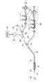
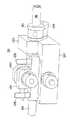
図1は、従来公知の心臓または抹消血管系のカテーテル挿入装置である。図示されているように、このカテーテル挿入装置は、内部ワイヤ10、管状のバルーンカテーテル12、および管状の誘導カテーテル14から成っている。バルーンカテーテル12は、誘導カテーテル14の対応する端部18から伸長している一端に、拡張バルーン16を有する。内部ワイヤ10は、バルーンカテーテル12の端部22から伸長している先端20を有する。 FIG. 1 shows a conventionally known heart or peripheral vascular system catheter insertion device. As shown, the catheter insertion device consists of an
第1Y字状アダプター24が誘導カテーテル14に固定されている。バルーンカテーテル12は、第1Y字状アダプター24の一つの脚部を通って伸長しており、配管26が他の脚部に取り付けられている。配管26は、コントラストおよび他の溶液を誘導カテーテル14へ送る。コントラスト溶液は、カテーテル挿入処置中に使用される画像装置上で、カテーテルを挿入している血管の視認性を向上し、医師がカテーテルを上手に誘導するのを可能にする。コントラストおよび他の溶液の注入とフラッシング(flushing)は、本技術で知られているように、装置28により制御される。 A first Y-shaped adapter 24 is fixed to the
継ぎ手30により、膨張器32とそれに接続した圧力計34、さらには、第2Y字状アダプター36の取り付けを可能にしている。内部ワイヤ10の使用者側の端部38は第2Y字状アダプター36の一つの脚部から伸長し、配管40は他の脚部から伸長している。配管40は、コントラストと他の溶液をバルーンカテーテル12へ送るために使用されるコントラストの注入兼フラッシング装置42に接続されている。 The
図1の実施態様において、内部ワイヤ10の端部20、38は僅かに曲げられている。使用者側の端部38において、医師は曲げ部分を使って内部ワイヤ10をその縦軸周りに回転すること(本明細書では「軸周りの回転」とも称する)ができる。内部側端部,即ち、誘導端部20において、曲げ部分により、カテーテルを挿入している血管への通路上の曲がり部分や分岐部を通して内部ワイヤ10を操作することができる。 In the embodiment of FIG. 1, the ends 20, 38 of the
心臓動脈のバルーン血管形成処置において、誘導カテーテル14は、その端部が手術される心臓動脈の開口近くの大動脈弓に位置するように、最初に患者の大腿部の動脈へ挿入される。誘導カテーテル14は、予め挿入された誘導ワイヤ(示されていない)に沿って滑らすことにより、上記位置に到達する。なお、誘導ワイヤは、誘導カテーテル14が所定の位置に置かれた後取り外される。次に、バルーンカテーテル12と内部ワイヤ10とは、一緒に、誘導カテーテル14を通りその端部まで押し込まれる。次に、内部ワイヤ10が膨張される範囲まで動脈内へ操作され、そして、バルーン16がワイヤ10に沿って所望の位置へ押し込まれる。この位置において、バルーン16は動脈の所望の拡張を達成するに必要なだけ膨張される。 In a balloon angioplasty procedure for a cardiac artery, the
図2は、カテーテル法を実行するための主従システムを示す。この主従システムは、主アクチュエータ50の一部であるカテーテル状の円筒形の制御器10'、12'、14'を使用している。従アクチュエータ52は、カテーテル14”のみならずカテーテル12”および患者54内のワイヤ10”(図2に示されていない)の動きを感知するとともに制御する。主アクチュエータ50と従アクチュエータ52とは、各駆動信号58およびセンサ信号60により電気的インタフェース回路56へ電気的に接続されている。流体装置62は、流体送り管64により従アクチュエータ52に接続されている。多様な装置の操作はコントロールパネル66により制御される。この操作には、カテーテル14を介して血管へ並びに血管を膨張させるためにバルーン16へコントラストおよび他の流体を注入することが含まれる。流体装置62は、コントロールパネル66からの制御信号に応答する電動弁を有する。また、この流体装置62は、コントロールパネル66の入力に応答してバルーン16の一連の時限膨張を選択的に行う。この特徴により、制限された開口を拡張するためにバルーン16を膨張する従来の方法が改善される。 FIG. 2 shows a master-slave system for performing catheterization. This master-slave system uses a catheter-like
アクチュエータ50、52は、制御器10’、12’、14’および器具10”、12”、14”の軸方向の移動と軸周りの回転とを感知するセンサを内蔵している。そして、これらの動きを示すパルスセンサ信号60がインタフェース回路56へ送られる。また、アクチュエータ50、52は、制御器10’、12’、14’および器具10”、12”、14”それぞれに係合するモータを内蔵している。これらモータは、インタフェース回路56が発生した駆動信号58に応答して、これらの構成要素の軸方向の移動と軸周りの回転運動とを起こす。 The
電気的インタフェース回路56は、駆動信号58およびセンサ信号60の電気的駆動回路と増幅回路、および、これら回路に接続されたプロセッサを有することが好ましい。このプロセッサは、主従制御プログラムを実行する。この主従制御プログラムは、カテーテル12”、14”およびワイヤ10”が制御器10’、12’、14’に指示されて患者内を移動するように、センサ信号60からの情報を使用して駆動信号58を発生する。これら移動は、連絡するカテーテルまたはワイヤの縦軸方向の移動と軸周りの回転の両方から成っている。主従制御プログラムは、「位置整合」として知られたタイプであることが好ましい。このタイプの制御プログラムでは、駆動信号58およびセンサ信号60は、可能ならば、各制御器10’、12’、14’および連絡するワイヤ10”あるいはカテーテル12”、14”の相対的位置が変化しないことを確実にするために使用される。例えば、制御器14’およびカテーテル14”の初期位置について考えると、使用者が制御器14’を1インチだけ内方へ押すとすると、制御プログラムがカテーテル14”を1インチだけ押して応答する。また、カテーテル14”がこの移動中に障害物に出会うとすると、使用者の動きに対向するフィードバック力が制御器14’に発生して制御器14’の位置をカテーテル14”の(拘束された)位置へ戻そうとする。 The
主従制御システムの利益の一つは、従装置が主装置からのすべての個々の入力にどのように応答するかを選択できることである。例えば、力または位置の位取りおよび震えの低減などの機能を有することが知られている。力または位置の位取りが使用される場合、従装置は、主装置に応答して、ある一定値に位取りされた同様な力が加えられるか同様な位置に移動される。例えば、2:1の位置の位取りを行う装置では、従装置は、主装置の2インチの動き毎に1インチ動く。位取りは、他の方向、すなわち、従装置から主装置への方向へも行われる。実際に、この2方向の位取りは、完全に所望の効果を達成するために、常に同時に使用される。位取りにより、使用者は、主装置のより大きい制御と対話しながら、小さい器具を操作することができる。震えを軽減するときは、他のタイプの動きによる従装置の動きに比し、特定の周波数帯域内で周期的であると認められるパターンの動きによる従装置の動きをより大きく減衰するように、主装置の入力をフィルタリングすることが行われる。電気的インタフェース56は、力または位置の位取り、震えの軽減、および、主従システムの効果を向上させる他の類似技法を選択的に使用する。 One benefit of the master-slave control system is that the slave device can select how it responds to all individual inputs from the master device. For example, it is known to have functions such as force or position scaling and trembling reduction. If force or position scaling is used, the slave device is responsive to the master device and a similar force scaled to a certain value is applied or moved to a similar position. For example, in a device that scales a 2: 1 position, the slave device moves 1 inch for every 2 inches of movement of the master device. The scaling is also performed in the other direction, that is, from the slave device to the master device. In practice, this bi-directional scale is always used simultaneously to achieve the full desired effect. Scale allows the user to manipulate small instruments while interacting with greater control of the main device. When reducing tremors, the movement of the slave device due to the movement of the pattern that is recognized as periodic within a certain frequency band is attenuated more than the movement of the slave device due to other types of movement. Filtering the input of the main unit is performed. The
電気的インタフェース56により得られる他の特徴は、事前にプログラム化された動作シーケンスを使用することである。例えば、コントロールパネル66からの信号に応答して、電気的インタフェース56は、ワイヤ10”を、人手をコントロールして行うよりも遥かに速く、高振動数で振動させることができる。例えば、ワイヤ10”を血管内の血液凝固中に突っ込んだ場合に、ワイヤ10”を自由にするためにこの振動が使用される。尚、応用場面によっては、電気的インタフェース56は、処置中に発生する特定の状態において、他のタイプの事前プログラム化されたシーケンスを有効に選択的に働かせることができる。 Another feature gained by the
図3は、図2の装置において主アクチュエータ50または従アクチュエータ52として使用されるアクチュエータアッセンブリ50−1の第1実施態様を示す。三つのアクチュエータ70がハウジング内のベース72に配置されている。アクチュエータ70は四角形で示されているが、この表現は単なる図示であって、アクチュエータ70の詳細は後記の図5〜9に示されている。ベース72の一端から、制御器10’、12’、14’がスリーブまたはグロメットを通ってベースに入っている。一組の強靱な同心連絡管76,78、80が、作動軸81に沿ってアクチュエータ70を通り筒形の状態で配置されている。図4に示されているように、制御器10’、12’、14’は、連絡継手82,84または86により連絡管76,78、80に接続されている。継ぎ手82,84、86は、テープ片、または、各連絡管と各カテーテルとの間の機械的接合を確実にする複雑な自動化された機械的器具である。 FIG. 3 shows a first embodiment of an actuator assembly 50-1 used as the
内側連絡管76、78はそれぞれ隣接した外側連絡管からさらに伸長して、アクチュエータ70のうちの一つの連絡アクチュエータと係合している。内側連絡管76、78それぞれが外側連絡管78または80から伸長している量は、他の連絡管の移動を干渉することなく、各連絡管が(図3の右の方へ)引っ込んだ位置と(図3の左の方へ)伸長した位置との間を自由に移動することができるように選択される。前記引っ込んだ位置は、患者に挿入されている実際の内部ワイヤ10、カテーテル12、14の最初の位置に相当する。また、伸長した位置は、実際の内部ワイヤ10またはカテーテル12、14がカテーテルを挿入している血管部分に押し込まれた後の、実際の内部ワイヤ10またはカテーテル12、14の最後の位置に相当する。 Each of the
アクチュエータ70は、各アクチュエータが作動中連絡管76、78、80と係合し、かつ、他の連絡管の移動の障害にならないように配置されている。各アクチュエータ70は、以下にさらに詳細に説明するセンサにより連絡管76,78、80の軸方向の移動と軸周りの回転を感知する。これらセンサは、センサ信号60により軸方向の移動と軸周りの回転の表示を行う。各アクチュエータ70には、駆動信号58の対応信号に応答して、連絡管76,78、80に軸方向の力とトルクを発生するモータが備えられている。アクチュエータ70は、以下にさらに詳細に説明されている。 The
図5は、アクチュエータ70の一つの実施態様を示す。支持脚台90がベース92から伸長している。一組の支持脚台90は、作動軸81に沿って支持脚台90の開孔を通って配置された軸部96、98により、送り台アッセンブリ94を支持している。また、移動制御ホイール102と回転制御ホイール104が、軸部96、98に支持されている。送り台アッセンブリ94と回転制御ホイール104とが軸98に固定されているので、回転制御ホイール104の回転により、送り台アッセンブリ94は作動軸81周りを回転する。移動制御ホイール102と送り台アッセンブリ94との間の接続は、図6により以下に詳細に説明されている。 FIG. 5 shows one embodiment of the
他の2組の支持脚台90は、駆動軸106、108を作動軸81と平行に支持している。各駆動軸106、108は、支持脚台90の対応する組の開孔を通って伸長している。駆動ホイール110、112は、それぞれ、駆動軸106、108に取り付けられている。駆動ホイール110は移動制御ホイール102と係合し、駆動ホイール112は回転制御ホイール104と係合している。 The other two sets of
主従アッセンブリ114、116は、それぞれ、駆動軸106、108に機械的に接続されている。アッセンブリ114、116内のモータは、駆動信号58に応答して対応する駆動軸106、108へトルクを作用させている。これらのモータは、好適には直流(DC)トルクモータである。各アッセンブリ114、116内のセンサは、対応する相互に配置されたモータの回転位置を検出する。これらセンサは、従来の回転位置エンコーダまたはすべての他の適切な装置でもよい。また、これらセンサは、各ホイール102、104の感知位置を示すセンサ信号60を発生する。例えば、センサ信号60は、それぞれ、一連のパルスであってもよく、各パルス信号が対応するモータの回転量を示す。 The master-
アッセンブリ116内のセンサにより発生したセンサ信号60は、アクチュエータ70内に配置された連絡管の回転位置を示す。アッセンブリ114内のセンサが発生したセンサ信号60は、後述のように、送り台アッセンブリ94内のギヤの構成により、軸方向の移動と軸周りの回転の情報の両方を供給する。従って、管の移動位置を得るために、回転のみを示すアッセンブリ114からのセンサ信号60が、軸方向の移動と軸周りの回転の両方を示すアッセンブリ116の信号から取除かれる。 A
図5のアクチュエータ70の動作中、連絡管76,78、80の一つは、作動軸81に沿ってアクチュエータ70を貫通して配置されている。使用者は、この連絡管を押し込み、引っ張りおよび回転する。この連絡管の引っ張りおよび押し込みにより、移動制御ホイール102は回転し、連絡管の回転により、ホイール102、104の両方を回転させる。ホイール102、104の回転は、アッセンブリ114、116内のエンコーダにより検出され、このエンコーダが発生したセンサ信号60の値が対応して変化する。図2のインタフェース56は、回路から位置の情報を受け取る。実行されている主従制御プログラムに従って、駆動信号58の値が所望の力とトルクが連絡管に作用するようにインタフェース56により決定される。そして、この駆動信号58によりアッセンブリ114、116内のモータが駆動される。また、これらモータにより、所望の力とトルクが軸106、108、ホイール110、112およびホイール102、104を介して加えられる。 During operation of the
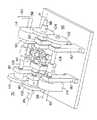
図6〜9は、送り台アッセンブリ94の詳細を示す。図6は、送り台アッセンブリ94の正面斜視図であり、図7は、ホイール140、122が連絡管76と係合している送り台アッセンブリ94の正面斜視図であり、図8は、非固定位置にある送り台アッセンブリ94の背面斜視図であり、図9は、固定位置にある送り台アッセンブリ94の背面斜視図である。 6-9 show the details of the
三つの側面を有する送り台本体120は、次の構成要素を支持する。即ち、軸部96、98、駆動ピンチホイール122、支柱126により支持されたクランプ部材124、相互に係合されたホイールまたはギヤ128、130、ホイール128と同じ軸に取り付けられたマイタホイールまたはギヤ132、および、ホイール130と同じ軸に取り付けられたカラー134。マイタホイール132は、駆動ピンチホイール122と同じ軸138に取り付けられた他のマイタホイールまたはギヤ136と係合している。アイドルピンチホイール140は、クランプ部材124に取り付けられている。 The
軸部98の作動軸81周りの回転により送り台94が作動軸81の周りに回転するように、送り台本体120が軸部分98に固定されている。本体120の作動軸81周りの回転から独立して、ホイール130が作動軸81の周りを回転できるように、ホイール130と保持カラー134が本体120に取り付けられている。また、ホイール128とマイタホイール132も送り台本体120に対し自由に回転するように取り付けられている。従って、ホイール130は、作動軸81周りの送り台本体120の回転に独立して、ホイール128によりマイタホイール132に回転を加える。 The
アクチュエータ70の使用が準備された状態で、クランプ部材124は、図8に示された非固定位置に移動される。連絡管76,78、80は、作動軸81に沿って軸部96、98に挿入される。次に、図7に示されているように、ピンチホイール122、140が、連絡管と係合するように、クランプ部材124が図9の固定位置へ移動される。図示されていないが、支柱126は、クランプ部材124を送り台本体120へ固定する助けとなるためにねじ込まれているのが好ましい。一組のスプリングが、送り台本体120とクランプ部材124の間に一つ、クランプ部材124と支柱126へねじ込まれた保持ナットとの間に一つ、各支柱126に配置されているのが好ましい。クランプ部材124は、この保持ナットを調節することにより、固定位置と非固定位置との間で移動される。 With the
アクチュエータ70の操作中に、使用者が連絡管を回転すると、送り台アッセンブリ94が作動軸81の周りを回転する。この回転は二つの働きをする。この回転は、図5の軸98、ホイール104、112、および、軸108を経て、アッセンブリ116内のエンコーダに伝達される。また、この回転は、次の機構によりアッセンブリ114内のエンコーダにも伝達される。即ち、送り台94が回転すると、ホイール128は作動軸81の周りを回転する。しかし、純粋な回転のためホイール128は送り台本体120に対し少しも回転しない。従って、ホイール130が回転していないホイール128により回転する。ホイール130の回転は、図5の軸96、ホイール102,110、および,軸106によりアッセンブリ114内のエンコーダへ伝達される。 When the user rotates the connecting tube during operation of the
使用者が連絡管を軸方向に移動することにより、ピンチホイール122が回転し、次に、マイタホイール136、132が回転する。この回転は、軸96と共に回転するホイール128、130、図5のホイール102,110および軸106を介してアッセンブリ114に伝達される。 When the user moves the connecting pipe in the axial direction, the
触覚的フィードバックは、アッセンブリ114、116内のモータにより、軸方向の移動とトルクが連絡管に加えられて、使用者へ伝えられる。モータのトルクが連絡管へ伝えられる機械的経路は、使用者が発した移動がエンコーダに伝達される上述の経路とは逆である。 Tactile feedback is transmitted to the user by means of motors in the
図10は、アクチュエータアッセンブリ50−2の第2実施態様を示し、図示されているように三つのアクチュエータ150,152,154を使用している。また、アクチュエータ70のように、アクチュエータ150,152,154は、軸方向の移動と軸周りの回転を感知でき発生させることができる。アクチュエータ150,152,154は、構造が相互にほぼ似ている。各アクチュエータ150,152,154は、断面形状が正方形の異なる大きさの剛性のある管と係合している。図10に示された管156は、制御器12’またはカテーテル12”へ取り付けられ、管158は、制御器10’またはワイヤ10”に取り付けられている。アクチュエータ154内の図10に示されていない管は、制御器14'に取り付けられている。各アクチュエータ150,152,154は、連絡管と係合している状態であるので、後述のようにそれらの内部構造は僅かに異なる。 FIG. 10 shows a second embodiment of the actuator assembly 50-2, using three
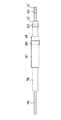
図11は、最外側のカテーテル14”と共に使用されるアクチュエータ154を示す。このアクチュエータ154は、リニアアクチュエータ160とロータリーアクチュエータ162を有する。リニアアクチュエータ160は、ほぼT字状の送り台161と、管166を把持するが、その管166をその縦軸の周りに回転させる回転軸受け164とを有する。この管166は最外側のカテーテル14”に取り付けられている。リニアアクチュエータ160は、レール168に沿って滑り、駆動プーリ172とアイドルプーリ174との間に伸長しているケープルループまたはケーブルベルト170に取り付けられている。駆動プーリ172はモータ176により回転し、その回転位置は、位置エンコーダまたは位置センサ180により感知される。リニアアクチュエータ160がレール168に沿って移動すると、管166は、回転位置が拘束されずにその軸に沿って移動する。 Figure 11 shows an
ロータリーアクチュエータ162は、管166が貫通している正方形の開孔を有するリニア軸受け184を備えている。リニア軸受け184は管166の回転位置を追跡し制御するが、管166をその縦軸に沿って移動させることができる。また、ロータリーアクチュエータ162は、ケーブルループまたはケーブルベルト188により駆動されるプーリ186、駆動プーリ190、およびモータ192に取り付けられている。回転位置エンコーダ194は、駆動プーリ190の回転位置を感知する。ロータリーアクチュエータ162が回転すると、管166もその移動位置を拘束されずにその縦軸に沿って回転する。示された実施態様において、管166は、その断面が正方形であるためにロータリーアクチュエータ162と共に回転するように拘束される。他の実施態様では、アクチュエータ150,152,154内の管は、三角形、六角形、スプラインなどの回転を拘束する他の断面形状としてもよい。 The
図10のアクチュエータ150、152は、軸受け162、164が細い管156、158を収容するように製作されていることを除いて、アクチュエータ154と本質的に同じである。また、管158は管166より十分に細く、その中で独立して回転し、同様に、管156は管158内で回転する。ベルト170、188は、プーリ172,174,186、190のリムの溝に乗っているスチール製のケーブルまたはベルトである。あるいは、プーリはスプロット状のホイールであってもよく、ベルト170、188は、チェーンまたはスプロケット状プーリの歯と係合するように表面が波打った他の構造としてもよい。 The
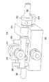
図12は図2の従アクチュエータ52を示すが、この従アクチュエータ52は、患者54に流体を注入することができる特徴がある。主アクチュエータ50のように、従アクチュエータ52は三つのアクチュエータ、例えば、図3のアクチュエータ70を有する。各アクチュエータ70は、ワイヤ10”およびカテーテル12”、14”の対応する一つと係合し、前述の連絡ワイヤまたはカテーテルの軸方向の移動と軸周りの回転を起こさせるために使用される。カテーテル12”、14”は、それぞれ一端に流体継ぎ手200を有する。図2の流体装置62からの管64は一組のバルブに接続されており、さらに、管204により継ぎ手200に接続されている。このバルブは、図2の流体装置62から患者54への流体の流れを制御するために使用される。カテーテル12”の継ぎ手200は、制御器10”の流体気密シールを有し、同様に、カテーテル14”の継ぎ手200は、カテーテル12”の流体気密シールを備えている。 FIG. 12 shows the
これまでの説明は、使用者がカテーテルなどの管状物体を遠隔操作することができるとともに、使用者に触覚的フィードバックを与える主従制御システムを述べた。当業者が、ここに開示された発明概念から逸脱することなく、上述の方法および装置を変更または変形できることは明らかである。従って、本発明は、添付請求の範囲の範囲と精神によってのみ限定されるとみなされるべきである。 The preceding description has described a master-slave control system that allows a user to remotely manipulate a tubular object such as a catheter and provides tactile feedback to the user. It will be apparent to those skilled in the art that the methods and apparatus described above can be modified or modified without departing from the inventive concepts disclosed herein. Accordingly, the invention should be viewed as limited only by the scope and spirit of the appended claims.
10’、12’、14’ 制御器、10、10” (器具の一部としての)ワイヤ、12、14、12”、14” (器具の一部としての)カテーテル、50 主アクチュエータ(第1アクチュエータ)、52 従アクチュエータ(第2アクチュエータ)、54 患者、56 (電気的)インタフェース(回路)、58 駆動信号、60 センサ信号、62 流体装置、64 流体送り装置、66 コントロールパネル、200 継ぎ手。 10 ', 12', 14 'controller, 10, 10 "wire (as part of instrument), 12, 14, 12", 14 "catheter (as part of instrument), 50 main actuator (first Actuator), 52 Slave actuator (second actuator), 54 Patient, 56 (Electrical) interface (circuit), 58 Drive signal, 60 Sensor signal, 62 Fluid device, 64 Fluid feeder, 66 Control panel, 200 Joint.
Claims (2)
Translated fromJapanese管状にして縦軸を有し、この縦軸方向の移動とこの縦軸周りの回転とを行うように使用者により操作される少なくとも一つの制御器と、
この制御器の1つとしての第1管状制御器に接続されたセンサとこの第1管状制御器に機械的に係合する第1電気モータとを有し、使用者による前記第1管状制御器の縦軸方向の移動と縦軸周りの回転に応答して前記第1管状制御器の縦軸方向の移動と縦軸周りの回転を示す第1電気センサ信号を発生するように動作するとともに、前記第1電気モータに対する駆動信号の選択的適用に応答して前記第1管状制御器の縦軸方向の移動と縦軸周りの回転とを起こすように動作する第1アクチュエータと、
前記器具の1つとしての第1カテーテルとこの第1カテーテルに機械的に係合する第2電気モータとに接続されたセンサを有し、前記第1カテーテルの軸方向の移動と軸周りの回転を示す第2電気センサ信号を発生するように動作するとともに、前記第2電気モータに対する駆動信号の選択的適用に応答して前記第1カテーテルの軸方向の移動と軸周りの回転とを起こすように動作する第2アクチュエータと、
入力信号として前記第1および第2電気センサ信号を受信し、かつ、使用者による前記第1管状制御器の動作に応答して前記第1カテーテルを動かすように前記第1および第2モータ駆動信号を発生するとともに、患者内部の前記第1カテーテルの動きに応答して前記第1管状制御器により触覚的フィードバックを使用者に提供するように動作する電気的インタフェースと
を有し、
さらに、前記第1カテーテルと同心である前記器具の1つとしての第2カテーテルと、
前記第1管状制御器と同心である前記制御器の1つとしての第2管状制御器と、
前記第2管状制御器に接続された前記第1アクチュエータ内のセンサと、
前記第2管状制御器に機械的に係合する前記第1アクチュエータ内の第3電気モータと、
前記第2カテーテルに接続された前記第2アクチュエータ内のセンサと、
前記第2カテーテルに機械的に係合する前記第2アクチュエータ内の第4電気モータと
を有し、
(1)前記第1アクチュエータは、使用者による前記第2管状制御器の軸方向の移動と軸周りの回転とに応答して前記第2管状制御器の軸方向の移動と軸周りの回転とを示す第3電気センサ信号を発生するように動作し、
(2)また、前記第1アクチュエータは、前記第3電気モータに対する駆動信号の選択的適用に応答して前記第2管状制御器の軸方向の移動と軸周りの回転とを起こさせるように動作し、
(3)前記第2アクチュエータは、前記第2カテーテルの軸方向の移動と軸周りの回転を示す第4電気センサ信号を発生するように動作し、
(4)また、前記第2アクチュエータは、前記第4電気モータに対する駆動信号の選択的適用に応答して前記第2カテーテルの軸方向の移動と軸周りの回転とを起こさせるように動作し、
(5)前記電気的インタフェースは、入力信号として前記第3および第4電気センサ信号を受信し、かつ、使用者による前記第2管状制御器の動きに応答して前記第2カテーテルを動かすように前記第3および第4モータ駆動信号を発生し、患者内部の前記第2カテーテルの動きに応答して触覚的フィードバックを使用者へ提供するように動作し、
さらに、前記第2カテーテルと同心である前記器具の1つとしてのワイヤと、
前記第2管状制御器と同心である前記制御器の1つとしての第3管状制御器と、
前記第3管状制御器に接続された前記第1アクチュエータ内のセンサと、
前記第3管状制御器に機械的に係合する前記第1アクチュエータ内の第5電気モータと、
前記ワイヤに接続された前記第2アクチュエータ内のセンサと、
前記ワイヤに機械的に係合する前記第2アクチュエータ内の第6電気モータと
を有し、
(6)前記第1アクチュエータは、使用者による前記第2管状制御器の軸方向の移動と軸周りの回転とに応答して、前記第2管状制御器の軸方向の移動と軸周りの回転の動きを示す第5電気センサ信号を発生するように動作し、
(7)前記第1アクチュエータは、前記第5電気モータに対する駆動信号の選択的適用に応答して、前記第3管状制御器の軸方向の移動と軸周りの回転とを起こさせるように動作し、
(8)前記第2アクチュエータは、前記ワイヤの軸方向の移動と軸周りの回転とを示す第6電気センサ信号を発生するように動作し、
(9)前記第2アクチュエータは、前記第6電気モータに対する駆動信号の選択的適用に応答して、前記ワイヤの軸方向の移動と軸周りの回転とを起こさせるように動作し、
(10)前記電気的インタフェースは、入力信号として前記第5および第6電気センサ信号を受信し、かつ、使用者による前記第3管状制御器の動きに応答して前記ワイヤを動かすように前記第5および第6モータ駆動信号を発生し、患者内部の前記ワイヤの動きに応答して触覚的フィードバックを使用者に提供するように動作し、
さらに、前記電気的インタフェースは、前記器具を動作させるとともに、触覚的フィードバックを使用者へ提供するように主従制御プログラムを実行するプロセッサを有し、
前記電気的インタフェースは、使用者による前記制御器の動きに応答して、前記器具を移動させる場合における力の位取り、位置の位取り、および、震えの内の一つ以上の軽減を行うように動作し、
さらに、前記電気的インタフェースは、使用者から発信された制御信号に応答する予めプログラム化された前記ワイヤの振動としての動作シーケンスを提供するように動作し、
さらに、患者の外部の端部において前記第1および第2カテーテルにそれぞれ取り付けられた第1および第2密閉流体継ぎ手と、前記第1および第2密閉流体継ぎ手に接続された流体システムであって、この流体システムと前記第1および第2カテーテルとの間の流体流れを制御するように使用者により操作されるバルブを備えた流体システムと
を有することを特徴とする医療器具操作装置。A medical instrument operating device used to manipulate at least one generally tubular instrument having a longitudinal axis and to insert the instrument into a patient in a microinvasive medical procedure,
At least one controller that is tubular and has a longitudinal axis and is operated by a user to perform movement in the longitudinal direction and rotation about the longitudinal axis;
A first tubular controller by a user having a sensor connected to a first tubular controller as one of the controllers and a first electric motor mechanically engaged with the first tubular controller. Operative to generate a first electrical sensor signal indicative of longitudinal movement and rotation about the longitudinal axis of the first tubular controller in response to movement of the longitudinal axis and rotation about the longitudinal axis, A first actuator that operates to cause longitudinal movement and rotation about the longitudinal axis of the first tubular controller in response to selective application of a drive signal to the first electric motor;
A sensor connected to a first catheter as one of the instruments and a second electric motor mechanically engaged with the first catheter, the axial movement and rotation about the axis of the first catheter; And generating axial movement and rotation about the axis in response to selective application of a drive signal to the second electric motor. A second actuator that operates on
Receiving the first and second electrical sensor signals as input signals and the first and second motor drive signals to move the first catheter in response to an operation of the first tubular controller by a user; And an electrical interface operative to provide haptic feedback to the user by the first tubular controller in response to movement of the first catheter within the patient;
A second catheter as one of the instruments concentric with the first catheter;
A second tubular controller as one of the controllers that is concentric with the first tubular controller;
A sensor in the first actuator connected to the second tubular controller;
A third electric motor in the first actuator that mechanically engages the second tubular controller;
A sensor in the second actuator connected to the second catheter;
A fourth electric motor in the second actuator that mechanically engages the second catheter;
(1) The first actuator is configured to perform axial movement and rotational movement of the second tubular controller in response to an axial movement and rotational movement of the second tubular controller by a user. Operating to generate a third electrical sensor signal indicative of
(2) The first actuator operates to cause axial movement and rotation around the second tubular controller in response to selective application of a drive signal to the third electric motor. And
(3) the second actuator operates to generate a fourth electrical sensor signal indicative of axial movement and rotation about the second catheter;
(4) In addition, the second actuator operates to cause axial movement and rotation about the axis of the second catheter in response to selective application of a drive signal to the fourth electric motor,
(5) The electrical interface receives the third and fourth electrical sensor signals as input signals and moves the second catheter in response to movement of the second tubular controller by a user. Generating the third and fourth motor drive signals and operative to provide tactile feedback to a user in response to movement of the second catheter within the patient;
A wire as one of the instruments that is concentric with the second catheter;
A third tubular controller as one of the controllers concentric with the second tubular controller;
A sensor in the first actuator connected to the third tubular controller;
A fifth electric motor in the first actuator that mechanically engages the third tubular controller;
A sensor in the second actuator connected to the wire;
A sixth electric motor in the second actuator that mechanically engages the wire;
(6) The first actuator moves in the axial direction and rotates around the axis of the second tubular controller in response to the axial movement and rotation around the axis of the second tubular controller by the user. Operate to generate a fifth electrical sensor signal indicative of movement of
(7) The first actuator operates to cause axial movement and rotation around the third tubular controller in response to selective application of a drive signal to the fifth electric motor. ,
(8) the second actuator operates to generate a sixth electrical sensor signal indicative of axial movement and rotation about the axis of the wire;
(9) The second actuator operates to cause axial movement and rotation of the wire in response to selective application of a drive signal to the sixth electric motor;
(10) The electrical interface receives the fifth and sixth electrical sensor signals as input signals and moves the wires in response to movement of the third tubular controller by a user. Generate 5 and 6 motor drive signals and operate to provide tactile feedback to the user in response to movement of the wire within the patient;
The electrical interface further includes a processor that executes the master-slave control program to operate the instrument and provide tactile feedback to the user;
The electrical interface is responsive to movement of the controller by a user to operate to reduce one or more of force scale, position scale, and tremor when moving the instrument And
In addition, the electrical interface operates to provide an operation sequence as vibration of the pre-programmed wire responsive to a control signal transmitted from a user;
And a fluid system connected to the first and second sealed fluid joints attached to the first and second catheters, respectively, at an external end of the patient, and the first and second sealed fluid joints, A medical device operating device comprising: a fluid system including a valve operated by a user to control fluid flow between the fluid system and the first and second catheters.
Applications Claiming Priority (1)
| Application Number | Priority Date | Filing Date | Title |
|---|---|---|---|
| US09/112,998US6096004A (en) | 1998-07-10 | 1998-07-10 | Master/slave system for the manipulation of tubular medical tools |
Related Parent Applications (1)
| Application Number | Title | Priority Date | Filing Date |
|---|---|---|---|
| JP11101693ADivisionJP2000042116A (en) | 1998-07-10 | 1999-04-08 | Medical instrument operating device |
Publications (1)
| Publication Number | Publication Date |
|---|---|
| JP2009061290Atrue JP2009061290A (en) | 2009-03-26 |
Family
ID=22347012
Family Applications (2)
| Application Number | Title | Priority Date | Filing Date |
|---|---|---|---|
| JP11101693APendingJP2000042116A (en) | 1998-07-10 | 1999-04-08 | Medical instrument operating device |
| JP2008275653APendingJP2009061290A (en) | 1998-07-10 | 2008-10-27 | Medical instrument manipulator |
Family Applications Before (1)
| Application Number | Title | Priority Date | Filing Date |
|---|---|---|---|
| JP11101693APendingJP2000042116A (en) | 1998-07-10 | 1999-04-08 | Medical instrument operating device |
Country Status (3)
| Country | Link |
|---|---|
| US (1) | US6096004A (en) |
| EP (1) | EP0970663A1 (en) |
| JP (2) | JP2000042116A (en) |
Cited By (1)
| Publication number | Priority date | Publication date | Assignee | Title |
|---|---|---|---|---|
| JP2024500541A (en)* | 2020-12-28 | 2024-01-09 | ロボカト | catheter robot |
Families Citing this family (212)
| Publication number | Priority date | Publication date | Assignee | Title |
|---|---|---|---|---|
| US7713190B2 (en) | 1998-02-24 | 2010-05-11 | Hansen Medical, Inc. | Flexible instrument |
| US7901399B2 (en) | 1998-02-24 | 2011-03-08 | Hansen Medical, Inc. | Interchangeable surgical instrument |
| US20020095175A1 (en) | 1998-02-24 | 2002-07-18 | Brock David L. | Flexible instrument |
| US7789875B2 (en) | 1998-02-24 | 2010-09-07 | Hansen Medical, Inc. | Surgical instruments |
| US6949106B2 (en) | 1998-02-24 | 2005-09-27 | Endovia Medical, Inc. | Surgical instrument |
| US6810281B2 (en) | 2000-12-21 | 2004-10-26 | Endovia Medical, Inc. | Medical mapping system |
| US7758569B2 (en) | 1998-02-24 | 2010-07-20 | Hansen Medical, Inc. | Interchangeable surgical instrument |
| US8414598B2 (en) | 1998-02-24 | 2013-04-09 | Hansen Medical, Inc. | Flexible instrument |
| US6860878B2 (en) | 1998-02-24 | 2005-03-01 | Endovia Medical Inc. | Interchangeable instrument |
| US7297142B2 (en)* | 1998-02-24 | 2007-11-20 | Hansen Medical, Inc. | Interchangeable surgical instrument |
| US7775972B2 (en) | 1998-02-24 | 2010-08-17 | Hansen Medical, Inc. | Flexible instrument |
| US7090683B2 (en) | 1998-02-24 | 2006-08-15 | Hansen Medical, Inc. | Flexible instrument |
| US8303576B2 (en) | 1998-02-24 | 2012-11-06 | Hansen Medical, Inc. | Interchangeable surgical instrument |
| US6398755B1 (en) | 1998-10-06 | 2002-06-04 | Scimed Life Systems, Inc. | Driveable catheter system |
| EP1224918A3 (en) | 1999-05-10 | 2002-12-18 | endoVia Medical Inc. | Surgical instrument |
| US6626899B2 (en) | 1999-06-25 | 2003-09-30 | Nidus Medical, Llc | Apparatus and methods for treating tissue |
| IL140136A (en)* | 2000-12-06 | 2010-06-16 | Intumed Ltd | Apparatus for self-guided intubation |
| US20030135204A1 (en) | 2001-02-15 | 2003-07-17 | Endo Via Medical, Inc. | Robotically controlled medical instrument with a flexible section |
| US7699835B2 (en) | 2001-02-15 | 2010-04-20 | Hansen Medical, Inc. | Robotically controlled surgical instruments |
| US8414505B1 (en) | 2001-02-15 | 2013-04-09 | Hansen Medical, Inc. | Catheter driver system |
| US20090182226A1 (en)* | 2001-02-15 | 2009-07-16 | Barry Weitzner | Catheter tracking system |
| US7766894B2 (en)* | 2001-02-15 | 2010-08-03 | Hansen Medical, Inc. | Coaxial catheter system |
| US20040243147A1 (en)* | 2001-07-03 | 2004-12-02 | Lipow Kenneth I. | Surgical robot and robotic controller |
| US7198630B2 (en)* | 2002-12-17 | 2007-04-03 | Kenneth I. Lipow | Method and apparatus for controlling a surgical robot to mimic, harmonize and enhance the natural neurophysiological behavior of a surgeon |
| DE10143291A1 (en)* | 2001-09-04 | 2003-03-20 | Thorsten Kern | Biopsy or injection system consists of an arrangement for applying implements, with an active haptic element which is separated from it spatially and mechanically |
| DE60120155T2 (en)* | 2001-09-10 | 2006-10-26 | Thermocore Medical Systems Nv | Arrangement for positioning catheters |
| EP1461104A4 (en)* | 2001-12-05 | 2005-01-19 | Intumed Ltd | Extendable tube |
| AU2003257309A1 (en) | 2002-08-13 | 2004-02-25 | Microbotics Corporation | Microsurgical robot system |
| US20040176751A1 (en) | 2002-08-14 | 2004-09-09 | Endovia Medical, Inc. | Robotic medical instrument system |
| US7331967B2 (en)* | 2002-09-09 | 2008-02-19 | Hansen Medical, Inc. | Surgical instrument coupling mechanism |
| DE10303270A1 (en)* | 2003-01-28 | 2004-08-05 | Technische Universität Darmstadt | Medical device with an elongated device |
| US8007511B2 (en)* | 2003-06-06 | 2011-08-30 | Hansen Medical, Inc. | Surgical instrument design |
| DE102004007935A1 (en)* | 2004-02-18 | 2005-05-25 | Siemens Ag | Method for moving probe in body of patient with remote control, using friction drive with rollers positioned parallel to probe |
| WO2005084542A1 (en)* | 2004-03-04 | 2005-09-15 | Agency For Science, Technology And Research | Apparatus for medical and/or simulation procedures |
| US7976539B2 (en) | 2004-03-05 | 2011-07-12 | Hansen Medical, Inc. | System and method for denaturing and fixing collagenous tissue |
| WO2005087128A1 (en) | 2004-03-05 | 2005-09-22 | Hansen Medical, Inc. | Robotic catheter system |
| EP1575015A1 (en)* | 2004-03-12 | 2005-09-14 | Xitact S.A. | Actuator for an elongated object for a force feedback generating device |
| US10863945B2 (en) | 2004-05-28 | 2020-12-15 | St. Jude Medical, Atrial Fibrillation Division, Inc. | Robotic surgical system with contact sensing feature |
| US7974674B2 (en) | 2004-05-28 | 2011-07-05 | St. Jude Medical, Atrial Fibrillation Division, Inc. | Robotic surgical system and method for surface modeling |
| US9782130B2 (en) | 2004-05-28 | 2017-10-10 | St. Jude Medical, Atrial Fibrillation Division, Inc. | Robotic surgical system |
| US8755864B2 (en) | 2004-05-28 | 2014-06-17 | St. Jude Medical, Atrial Fibrillation Division, Inc. | Robotic surgical system and method for diagnostic data mapping |
| US10258285B2 (en) | 2004-05-28 | 2019-04-16 | St. Jude Medical, Atrial Fibrillation Division, Inc. | Robotic surgical system and method for automated creation of ablation lesions |
| US7632265B2 (en) | 2004-05-28 | 2009-12-15 | St. Jude Medical, Atrial Fibrillation Division, Inc. | Radio frequency ablation servo catheter and method |
| US8528565B2 (en) | 2004-05-28 | 2013-09-10 | St. Jude Medical, Atrial Fibrillation Division, Inc. | Robotic surgical system and method for automated therapy delivery |
| IL162318A (en) | 2004-06-03 | 2011-07-31 | Tal Wenderow | Transmission for a remote catheterization system |
| EP4197447A1 (en)* | 2004-08-16 | 2023-06-21 | Corindus, Inc. | Image-guided navigation for catheter-based interventions |
| CA2578779C (en)* | 2004-08-30 | 2012-08-21 | Synthes (U.S.A.) | A hand-held motorized injection device with haptic feedback for highly viscous materials |
| US7478247B2 (en)* | 2004-11-10 | 2009-01-13 | Hillcrest Laboratories, Inc. | Methods and systems for securing data processing devices |
| US7542816B2 (en) | 2005-01-27 | 2009-06-02 | Outland Research, Llc | System, method and computer program product for automatically selecting, suggesting and playing music media files |
| US7562117B2 (en) | 2005-09-09 | 2009-07-14 | Outland Research, Llc | System, method and computer program product for collaborative broadcast media |
| US20070189544A1 (en) | 2005-01-15 | 2007-08-16 | Outland Research, Llc | Ambient sound responsive media player |
| US7489979B2 (en) | 2005-01-27 | 2009-02-10 | Outland Research, Llc | System, method and computer program product for rejecting or deferring the playing of a media file retrieved by an automated process |
| DE102005003171A1 (en)* | 2005-01-19 | 2006-08-03 | Biotronik Crm Patent Ag | Medical catheter has an integral power supply and a wireless data transfer interface for the transmission of medical data and measurements to an external diagnosis and control device |
| US20100312129A1 (en) | 2005-01-26 | 2010-12-09 | Schecter Stuart O | Cardiovascular haptic handle system |
| US8257302B2 (en)* | 2005-05-10 | 2012-09-04 | Corindus, Inc. | User interface for remote control catheterization |
| US8155910B2 (en) | 2005-05-27 | 2012-04-10 | St. Jude Medical, Atrial Fibrillation Divison, Inc. | Robotically controlled catheter and method of its calibration |
| JP2009500086A (en) | 2005-07-01 | 2009-01-08 | ハンセン メディカル,インク. | Robotic guide catheter system |
| EP1907042B1 (en) | 2005-07-06 | 2009-03-11 | Vascular Pathways Inc. | Intravenous catheter insertion device and method of use |
| EP1907041B1 (en)* | 2005-07-11 | 2019-02-20 | Catheter Precision, Inc. | Remotely controlled catheter insertion system |
| US7519537B2 (en) | 2005-07-19 | 2009-04-14 | Outland Research, Llc | Method and apparatus for a verbo-manual gesture interface |
| US8176101B2 (en) | 2006-02-07 | 2012-05-08 | Google Inc. | Collaborative rejection of media for physical establishments |
| CA2520942C (en)* | 2005-09-23 | 2013-03-19 | Queen's University At Kingston | Tactile amplification instrument and method of use |
| US7917148B2 (en) | 2005-09-23 | 2011-03-29 | Outland Research, Llc | Social musical media rating system and method for localized establishments |
| WO2007036925A1 (en)* | 2005-09-29 | 2007-04-05 | Corindus Ltd. | Methods and apparatuses for treatment of hollow organs |
| US7577522B2 (en) | 2005-12-05 | 2009-08-18 | Outland Research, Llc | Spatially associated personal reminder system and method |
| US7586032B2 (en) | 2005-10-07 | 2009-09-08 | Outland Research, Llc | Shake responsive portable media player |
| US20070103437A1 (en)* | 2005-10-26 | 2007-05-10 | Outland Research, Llc | Haptic metering for minimally invasive medical procedures |
| CN101351236B (en)* | 2005-11-15 | 2013-05-29 | 约翰霍普金斯大学 | An active sleeve for biosensing and surgery |
| FR2893851B1 (en) | 2005-11-30 | 2008-02-08 | Philippe Bencteux | CATHETER ROLLER / DEROULER AND ARTERIOGRAPHY SYSTEM EQUIPPED WITH SUCH ROLLER / DEROULEUR |
| JP4878513B2 (en)* | 2006-03-27 | 2012-02-15 | 国立大学法人 名古屋工業大学 | Apparatus and method for measuring compressive force of flexible linear body |
| WO2007146984A2 (en) | 2006-06-13 | 2007-12-21 | Intuitive Surgical, Inc. | Control system configured to compensate for non-ideal actuator-to-joint linkage characteristics in a medical robotic system |
| JP5177352B2 (en)* | 2007-04-10 | 2013-04-03 | 国立大学法人 名古屋工業大学 | Linear body drive device |
| EP2150304B1 (en)* | 2007-05-07 | 2010-12-01 | Vascular Pathways Inc. | Intravenous catheter insertion and blood sample devices and method of use |
| US20090069830A1 (en)* | 2007-06-07 | 2009-03-12 | Piezo Resonance Innovations, Inc. | Eye surgical tool |
| US10219832B2 (en) | 2007-06-29 | 2019-03-05 | Actuated Medical, Inc. | Device and method for less forceful tissue puncture |
| US8328738B2 (en)* | 2007-06-29 | 2012-12-11 | Actuated Medical, Inc. | Medical tool for reduced penetration force with feedback means |
| US9987468B2 (en) | 2007-06-29 | 2018-06-05 | Actuated Medical, Inc. | Reduced force device for intravascular access and guidewire placement |
| WO2009006291A1 (en)* | 2007-06-29 | 2009-01-08 | Piezo Resonance Innovations, Inc. | Medical tool for reduced penetration force |
| US20110046659A1 (en)* | 2007-07-09 | 2011-02-24 | Immersion Corporation | Minimally Invasive Surgical Tools With Haptic Feedback |
| US20090024140A1 (en)* | 2007-07-20 | 2009-01-22 | Searete Llc, A Limited Liability Corporation Of The State Of Delaware | Surgical feedback system |
| US20090157059A1 (en)* | 2007-12-14 | 2009-06-18 | Searete Llc, A Limited Liability Corporation Of The State Of Delaware | Surgical instrument navigation system |
| US9211160B2 (en) | 2008-01-16 | 2015-12-15 | Luiz Geraldo Pivotto | Remotely controlled catheter insertion system with automatic control system |
| WO2009092059A2 (en) | 2008-01-16 | 2009-07-23 | Catheter Robotics, Inc. | Remotely controlled catheter insertion system |
| US8740840B2 (en)* | 2008-01-16 | 2014-06-03 | Catheter Robotics Inc. | Remotely controlled catheter insertion system |
| US8986246B2 (en) | 2008-01-16 | 2015-03-24 | Catheter Robotics Inc. | Remotely controlled catheter insertion system |
| JP5322153B2 (en) | 2008-03-25 | 2013-10-23 | Ntn株式会社 | Drive device for medical linear body |
| US9161817B2 (en) | 2008-03-27 | 2015-10-20 | St. Jude Medical, Atrial Fibrillation Division, Inc. | Robotic catheter system |
| US20090248042A1 (en)* | 2008-03-27 | 2009-10-01 | Kirschenman Mark B | Model catheter input device |
| EP2266473B1 (en)* | 2008-04-10 | 2015-07-15 | NTN Corporation | Linear object operation controller which controls operation of linear object by operator |
| JP2009273827A (en)* | 2008-05-19 | 2009-11-26 | Ntn Corp | Linear object operation controller |
| WO2009137410A1 (en)* | 2008-05-06 | 2009-11-12 | Corindus Ltd. | Catheter system |
| JP5334035B2 (en)* | 2008-05-29 | 2013-11-06 | Ntn株式会社 | Coil insertion device |
| EP2320990B2 (en)* | 2008-08-29 | 2023-05-31 | Corindus, Inc. | Catheter control system and graphical user interface |
| WO2010025336A1 (en)* | 2008-08-29 | 2010-03-04 | Corindus Ltd. | Catheter simulation and assistance system |
| US9679499B2 (en)* | 2008-09-15 | 2017-06-13 | Immersion Medical, Inc. | Systems and methods for sensing hand motion by measuring remote displacement |
| JP5403785B2 (en) | 2008-10-15 | 2014-01-29 | 国立大学法人 名古屋工業大学 | Insertion device |
| US8594799B2 (en)* | 2008-10-31 | 2013-11-26 | Advanced Bionics | Cochlear electrode insertion |
| WO2010068783A1 (en) | 2008-12-12 | 2010-06-17 | Corindus Inc. | Remote catheter procedure system |
| US8708211B2 (en) | 2009-02-12 | 2014-04-29 | Covidien Lp | Powered surgical instrument with secondary circuit board |
| EP2408509B1 (en)* | 2009-03-18 | 2023-08-09 | Corindus, Inc. | Remote catheter system with steerable catheter |
| US9254123B2 (en) | 2009-04-29 | 2016-02-09 | Hansen Medical, Inc. | Flexible and steerable elongate instruments with shape control and support elements |
| WO2010138499A1 (en)* | 2009-05-25 | 2010-12-02 | Stereotaxis, Inc. | Remote manipulator device |
| JP5313777B2 (en)* | 2009-06-11 | 2013-10-09 | 国立大学法人 筑波大学 | Catheter device |
| WO2011028627A2 (en)* | 2009-08-26 | 2011-03-10 | The Research Foundation Of State University Of New York | System and method for endovascular telerobotic access |
| ITBO20090074U1 (en)* | 2009-09-30 | 2011-04-01 | Tre Esse Progettazione Biomedica S R L | INTERFACE FOR DRIVING FROM REMOTE POSITION OF A ROBOTIC MANIPULATOR FOR STEERABLE CATHETER MANEUVERING IN THE HUMAN CARDIOVASCULAR SYSTEM. |
| US9962229B2 (en) | 2009-10-12 | 2018-05-08 | Corindus, Inc. | System and method for navigating a guide wire |
| EP2488245B1 (en) | 2009-10-12 | 2019-02-20 | Corindus, Inc. | Catheter system with percutaneous device movement algorithm |
| US20120203168A1 (en) | 2009-10-14 | 2012-08-09 | Hideo Fujimoto | Insertion device, training device, and recording system |
| US9211403B2 (en)* | 2009-10-30 | 2015-12-15 | Advanced Bionics, Llc | Steerable stylet |
| RU2555381C2 (en)* | 2009-11-12 | 2015-07-10 | Конинклейке Филипс Электроникс Н.В. | Guidance system and catheter system |
| JP5775881B2 (en)* | 2010-01-15 | 2015-09-09 | イマージョン コーポレーションImmersion Corporation | System and method for minimally invasive surgical tools with tactile feedback |
| US10384039B2 (en) | 2010-05-14 | 2019-08-20 | C. R. Bard, Inc. | Catheter insertion device including top-mounted advancement components |
| US9950139B2 (en) | 2010-05-14 | 2018-04-24 | C. R. Bard, Inc. | Catheter placement device including guidewire and catheter control elements |
| US9872971B2 (en) | 2010-05-14 | 2018-01-23 | C. R. Bard, Inc. | Guidewire extension system for a catheter placement device |
| US8932258B2 (en) | 2010-05-14 | 2015-01-13 | C. R. Bard, Inc. | Catheter placement device and method |
| US11925779B2 (en) | 2010-05-14 | 2024-03-12 | C. R. Bard, Inc. | Catheter insertion device including top-mounted advancement components |
| US9498107B2 (en) | 2010-08-06 | 2016-11-22 | Carefusion 2200, Inc. | Clamping system |
| EP2417925B1 (en) | 2010-08-12 | 2016-12-07 | Immersion Corporation | Electrosurgical tool having tactile feedback |
| US8776800B2 (en) | 2010-09-30 | 2014-07-15 | Carefusion 2200, Inc. | Sterile drape having multiple drape interface mechanisms |
| US9833293B2 (en) | 2010-09-17 | 2017-12-05 | Corindus, Inc. | Robotic catheter system |
| US20120071752A1 (en)* | 2010-09-17 | 2012-03-22 | Sewell Christopher M | User interface and method for operating a robotic medical system |
| US8740883B2 (en) | 2010-09-30 | 2014-06-03 | Carefusion 2200, Inc. | Detachable handle mechanism for use in instrument positioning |
| US8640706B2 (en) | 2010-09-30 | 2014-02-04 | Carefusion 2200, Inc. | Interface mechanism between a drape and a handle |
| WO2012044590A2 (en)* | 2010-09-30 | 2012-04-05 | Carefusion 2200, Inc. | Interface mechanism and detachable shaft |
| US8801710B2 (en) | 2010-12-07 | 2014-08-12 | Immersion Corporation | Electrosurgical sealing tool having haptic feedback |
| US8523043B2 (en) | 2010-12-07 | 2013-09-03 | Immersion Corporation | Surgical stapler having haptic feedback |
| US20120191079A1 (en) | 2011-01-20 | 2012-07-26 | Hansen Medical, Inc. | System and method for endoluminal and translumenal therapy |
| US8690833B2 (en) | 2011-01-31 | 2014-04-08 | Vascular Pathways, Inc. | Intravenous catheter and insertion device with reduced blood spatter |
| ES2835652T3 (en) | 2011-02-25 | 2021-06-22 | Bard Inc C R | Medical component insertion device including a retractable needle |
| US8942828B1 (en) | 2011-04-13 | 2015-01-27 | Stuart Schecter, LLC | Minimally invasive cardiovascular support system with true haptic coupling |
| USD903101S1 (en) | 2011-05-13 | 2020-11-24 | C. R. Bard, Inc. | Catheter |
| US8845667B2 (en) | 2011-07-18 | 2014-09-30 | Immersion Corporation | Surgical tool having a programmable rotary module for providing haptic feedback |
| US20130030363A1 (en) | 2011-07-29 | 2013-01-31 | Hansen Medical, Inc. | Systems and methods utilizing shape sensing fibers |
| WO2013036909A1 (en)* | 2011-09-09 | 2013-03-14 | Children's National Medical Center | Enhanced control of flexible endoscopes through human-machine interface |
| US9402555B2 (en)* | 2011-12-29 | 2016-08-02 | St. Jude Medical, Atrial Fibrillation Division, Inc. | Drive assembly for use in a robotic control and guidance system |
| US10013082B2 (en) | 2012-06-05 | 2018-07-03 | Stuart Schecter, LLC | Operating system with haptic interface for minimally invasive, hand-held surgical instrument |
| US9245428B2 (en) | 2012-08-02 | 2016-01-26 | Immersion Corporation | Systems and methods for haptic remote control gaming |
| US20140066900A1 (en) | 2012-09-06 | 2014-03-06 | Corindus, Inc. | System for guide catheter control |
| GB201217905D0 (en)* | 2012-10-05 | 2012-11-21 | Imp Innovations Ltd | A device |
| US20140148673A1 (en) | 2012-11-28 | 2014-05-29 | Hansen Medical, Inc. | Method of anchoring pullwire directly articulatable region in catheter |
| FR2999939B1 (en)* | 2012-12-21 | 2015-01-16 | Robocath | CATHETERISM SYSTEM TRAINING MODULE |
| WO2014120741A1 (en) | 2013-01-30 | 2014-08-07 | Vascular Pathways, Inc. | Systems and methods for venipuncture and catheter placement |
| US9533121B2 (en) | 2013-02-26 | 2017-01-03 | Catheter Precision, Inc. | Components and methods for accommodating guidewire catheters on a catheter controller system |
| FR3002851B1 (en)* | 2013-03-07 | 2015-06-19 | Robocath | ROBOTISE CATHETERISM SYSTEM TRAINING MODULE. |
| US9566414B2 (en) | 2013-03-13 | 2017-02-14 | Hansen Medical, Inc. | Integrated catheter and guide wire controller |
| US20140277334A1 (en) | 2013-03-14 | 2014-09-18 | Hansen Medical, Inc. | Active drives for robotic catheter manipulators |
| US9326822B2 (en) | 2013-03-14 | 2016-05-03 | Hansen Medical, Inc. | Active drives for robotic catheter manipulators |
| US20140276392A1 (en)* | 2013-03-15 | 2014-09-18 | Hansen Medical, Inc. | Input device for robotic catheter and guide wire system |
| US9549783B2 (en)* | 2013-03-15 | 2017-01-24 | Corindus, Inc. | Catheter system with magnetic coupling |
| US10849702B2 (en) | 2013-03-15 | 2020-12-01 | Auris Health, Inc. | User input devices for controlling manipulation of guidewires and catheters |
| US9283046B2 (en) | 2013-03-15 | 2016-03-15 | Hansen Medical, Inc. | User interface for active drive apparatus with finite range of motion |
| US9408669B2 (en) | 2013-03-15 | 2016-08-09 | Hansen Medical, Inc. | Active drive mechanism with finite range of motion |
| US20140276936A1 (en) | 2013-03-15 | 2014-09-18 | Hansen Medical, Inc. | Active drive mechanism for simultaneous rotation and translation |
| KR102115447B1 (en)* | 2013-03-27 | 2020-05-27 | 한양대학교 에리카산학협력단 | Endoscope apparatus |
| EP2979613B1 (en)* | 2013-03-29 | 2022-10-12 | FUJIFILM Corporation | Device for endoscopic surgery |
| JP6093850B2 (en)* | 2013-03-29 | 2017-03-08 | 富士フイルム株式会社 | Endoscopic surgical device |
| EP2979615B1 (en)* | 2013-03-29 | 2019-11-27 | FUJIFILM Corporation | Device for endoscopic surgery |
| US11020016B2 (en) | 2013-05-30 | 2021-06-01 | Auris Health, Inc. | System and method for displaying anatomy and devices on a movable display |
| US11114918B2 (en) | 2013-06-26 | 2021-09-07 | Corindus, Inc. | Differential drive |
| JP6164964B2 (en)* | 2013-07-26 | 2017-07-19 | オリンパス株式会社 | Medical system and control method thereof |
| US9724493B2 (en) | 2013-08-27 | 2017-08-08 | Catheter Precision, Inc. | Components and methods for balancing a catheter controller system with a counterweight |
| US9993614B2 (en) | 2013-08-27 | 2018-06-12 | Catheter Precision, Inc. | Components for multiple axis control of a catheter in a catheter positioning system |
| US9750577B2 (en) | 2013-09-06 | 2017-09-05 | Catheter Precision, Inc. | Single hand operated remote controller for remote catheter positioning system |
| US9999751B2 (en) | 2013-09-06 | 2018-06-19 | Catheter Precision, Inc. | Adjustable nose cone for a catheter positioning system |
| US9795764B2 (en) | 2013-09-27 | 2017-10-24 | Catheter Precision, Inc. | Remote catheter positioning system with hoop drive assembly |
| US9700698B2 (en) | 2013-09-27 | 2017-07-11 | Catheter Precision, Inc. | Components and methods for a catheter positioning system with a spreader and track |
| EP3243476B1 (en) | 2014-03-24 | 2019-11-06 | Auris Health, Inc. | Systems and devices for catheter driving instinctiveness |
| US10046140B2 (en) | 2014-04-21 | 2018-08-14 | Hansen Medical, Inc. | Devices, systems, and methods for controlling active drive systems |
| US10569052B2 (en) | 2014-05-15 | 2020-02-25 | Auris Health, Inc. | Anti-buckling mechanisms for catheters |
| KR101712417B1 (en)* | 2014-06-23 | 2017-03-06 | 한양대학교 에리카산학협력단 | Robotic Procedure |
| WO2016037127A1 (en) | 2014-09-05 | 2016-03-10 | C.R. Bard, Inc. | Catheter insertion device including retractable needle |
| WO2016090270A1 (en) | 2014-12-05 | 2016-06-09 | Corindus, Inc. | System and method for navigating a guide wire |
| USD903100S1 (en) | 2015-05-01 | 2020-11-24 | C. R. Bard, Inc. | Catheter placement device |
| CN113350614A (en) | 2015-05-15 | 2021-09-07 | C·R·巴德股份有限公司 | Catheter placement device including extendable needle safety feature |
| US10940292B2 (en) | 2015-07-08 | 2021-03-09 | Actuated Medical, Inc. | Reduced force device for intravascular access and guidewire placement |
| JP6560929B2 (en)* | 2015-08-04 | 2019-08-14 | 東レエンジニアリング株式会社 | Operation feeling reproduction device |
| US11793543B2 (en) | 2015-09-18 | 2023-10-24 | Obvius Robotics, Inc. | Device and method for automated insertion of penetrating member |
| US10134306B2 (en)* | 2016-02-26 | 2018-11-20 | Cae Healthcare Canada Inc. | Apparatus for simulating insertion of an elongated instrument into a structure and medical insertion simulator |
| US20170249865A1 (en)* | 2016-02-26 | 2017-08-31 | Cae Healthcare Canada Inc. | Apparatus for simulating insertion of an elongated instrument into a structure providing axial rotating connection of the elongated instrument to a carriage |
| CA2921852C (en)* | 2016-02-26 | 2016-11-29 | Cae Healthcare Canada Inc. | Apparatus for simulating insertion of an elongated instrument into a structure and medical insertion simulator |
| US10078040B2 (en) | 2016-07-20 | 2018-09-18 | Champlain Cable Corp. | Wire flexibility testing apparatus |
| US11037464B2 (en) | 2016-07-21 | 2021-06-15 | Auris Health, Inc. | System with emulator movement tracking for controlling medical devices |
| US10463439B2 (en) | 2016-08-26 | 2019-11-05 | Auris Health, Inc. | Steerable catheter with shaft load distributions |
| US11241559B2 (en) | 2016-08-29 | 2022-02-08 | Auris Health, Inc. | Active drive for guidewire manipulation |
| US10493262B2 (en) | 2016-09-12 | 2019-12-03 | C. R. Bard, Inc. | Blood control for a catheter insertion device |
| US10426616B2 (en)* | 2016-11-17 | 2019-10-01 | Evalve, Inc. | Cardiac implant delivery system |
| EP3585471B1 (en) | 2017-03-01 | 2025-01-01 | C. R. Bard, Inc. | Catheter insertion device |
| CN107184274B (en)* | 2017-06-05 | 2020-03-31 | 上海速介机器人科技有限公司 | Vascular intervention operation robot operating handle with hand feeling and control method thereof |
| IT201800009380A1 (en)* | 2018-10-11 | 2020-04-11 | Guido Danieli | Robotic System for Angioplasty and Endoluminary Surgery |
| IT201700114767A1 (en)* | 2017-10-26 | 2018-01-26 | Guido Danieli | Robotic System for Angioplasty |
| EP3700454A1 (en)* | 2017-10-26 | 2020-09-02 | Guido Danieli | Robotic system for angioplasty and endoluminar surgery |
| WO2019113391A1 (en) | 2017-12-08 | 2019-06-13 | Auris Health, Inc. | System and method for medical instrument navigation and targeting |
| ES2980192T3 (en) | 2018-03-07 | 2024-09-30 | Bard Access Systems Inc | Guidewire advancement and blood reflux systems for a medical device insertion system |
| KR102184889B1 (en)* | 2018-04-19 | 2020-12-01 | (주)엘엔로보틱스 | Roller module for medical robot, driving apparatus for medical robot and medical robot |
| US11179213B2 (en) | 2018-05-18 | 2021-11-23 | Auris Health, Inc. | Controllers for robotically-enabled teleoperated systems |
| USD921884S1 (en) | 2018-07-27 | 2021-06-08 | Bard Access Systems, Inc. | Catheter insertion device |
| US11589936B1 (en) | 2019-01-07 | 2023-02-28 | Arthur John Ulm, III | Robotic surgical system |
| US11628020B2 (en) | 2019-06-19 | 2023-04-18 | Virtuoso Surgical, Inc. | Insertable robot for minimally invasive surgery |
| WO2020264418A1 (en) | 2019-06-28 | 2020-12-30 | Auris Health, Inc. | Console overlay and methods of using same |
| CA3151126A1 (en) | 2019-08-19 | 2021-02-25 | Becton, Dickinson And Company | Midline catheter placement device |
| JP7530177B2 (en)* | 2020-01-31 | 2024-08-07 | 朝日インテック株式会社 | Chemical injection device |
| JP7660224B2 (en)* | 2021-05-26 | 2025-04-10 | 普鋭醫療(香港)有限公司 | Robotic Surgical Devices and Delivery Systems |
| JP7540118B6 (en)* | 2021-07-05 | 2024-09-12 | 深▲せん▼愛博合創医療机器人有限公司 | Interventional Surgery Robot Slave Device |
| US12419703B2 (en) | 2022-08-01 | 2025-09-23 | Imperative Care, Inc. | Robotic drive system for achieving supra-aortic access |
| US20230052862A1 (en)* | 2021-08-12 | 2023-02-16 | Imperative Care, Inc. | Sterile packaging assembly for robotic interventional device |
| JPWO2023074335A1 (en)* | 2021-10-29 | 2023-05-04 | ||
| US20240041480A1 (en) | 2022-08-02 | 2024-02-08 | Imperative Care, Inc. | Multi catheter system with integrated fluidics management |
| US20240181213A1 (en) | 2022-12-01 | 2024-06-06 | Imperative Care, Inc. | Drive table with shuttle |
| US12377206B2 (en) | 2023-05-17 | 2025-08-05 | Imperative Care, Inc. | Fluidics control system for multi catheter stack |
| US12426965B2 (en) | 2023-06-15 | 2025-09-30 | Obvius Robotics, Inc. | Image-guided robotic arm for inserting a penetrating member into a body lumen |
| KR102727987B1 (en) | 2023-07-31 | 2024-11-08 | 고려대학교 산학협력단 | Automatic insertion of tubular surgical tools |
| WO2025117011A1 (en)* | 2023-11-29 | 2025-06-05 | Syncrobotix Inc., A United States State Of Delaware Corporation | Rotary and linear actuated robotic catheter steering system |
Citations (4)
| Publication number | Priority date | Publication date | Assignee | Title |
|---|---|---|---|---|
| JPH06105914A (en)* | 1992-09-14 | 1994-04-19 | Interventional Technol Inc | Guide line vibration device |
| JPH07184909A (en)* | 1993-12-27 | 1995-07-25 | Olympus Optical Co Ltd | Treating device |
| JPH08126646A (en)* | 1994-10-24 | 1996-05-21 | Interventional Technol Inc | Guide wire vibrating instrument |
| JPH10179756A (en)* | 1996-12-26 | 1998-07-07 | Kanegafuchi Chem Ind Co Ltd | Balloon catheter |
Family Cites Families (14)
| Publication number | Priority date | Publication date | Assignee | Title |
|---|---|---|---|---|
| DE2813275A1 (en)* | 1978-03-28 | 1979-10-11 | Fresenius Chem Pharm Ind | DOUBLE LUMEN CATHETER |
| US4655746A (en)* | 1985-12-02 | 1987-04-07 | Target Therapeutics | Catheter device |
| US4925444A (en)* | 1987-08-07 | 1990-05-15 | Baxter Travenol Laboratories, Inc. | Closed multi-fluid delivery system and method |
| CA2054961C (en)* | 1990-12-14 | 1997-09-30 | James R. Gross | Multilumen catheter |
| US5339799A (en)* | 1991-04-23 | 1994-08-23 | Olympus Optical Co., Ltd. | Medical system for reproducing a state of contact of the treatment section in the operation unit |
| JP3197310B2 (en)* | 1991-07-24 | 2001-08-13 | オリンパス光学工業株式会社 | Treatment device |
| US5631973A (en)* | 1994-05-05 | 1997-05-20 | Sri International | Method for telemanipulation with telepresence |
| CA2128606C (en)* | 1992-01-21 | 2008-07-22 | Philip S. Green | Teleoperator system and method with telepresence |
| DE4417400A1 (en)* | 1994-05-18 | 1995-11-23 | D T I Dr Trippe Ingenieurgesel | Carrier system made of proboscis, which can be adjusted in their spatial shape |
| US5882206A (en)* | 1995-03-29 | 1999-03-16 | Gillio; Robert G. | Virtual surgery system |
| JP3756556B2 (en)* | 1995-10-06 | 2006-03-15 | オリンパス株式会社 | Grasping forceps |
| US5624398A (en)* | 1996-02-08 | 1997-04-29 | Symbiosis Corporation | Endoscopic robotic surgical tools and methods |
| US5807377A (en)* | 1996-05-20 | 1998-09-15 | Intuitive Surgical, Inc. | Force-reflecting surgical instrument and positioning mechanism for performing minimally invasive surgery with enhanced dexterity and sensitivity |
| JP3550966B2 (en)* | 1996-09-18 | 2004-08-04 | 株式会社日立製作所 | Surgical equipment |
- 1998
- 1998-07-10USUS09/112,998patent/US6096004A/ennot_activeExpired - Lifetime
- 1999
- 1999-04-08JPJP11101693Apatent/JP2000042116A/enactivePending
- 1999-04-29EPEP99108416Apatent/EP0970663A1/ennot_activeWithdrawn
- 2008
- 2008-10-27JPJP2008275653Apatent/JP2009061290A/enactivePending
Patent Citations (4)
| Publication number | Priority date | Publication date | Assignee | Title |
|---|---|---|---|---|
| JPH06105914A (en)* | 1992-09-14 | 1994-04-19 | Interventional Technol Inc | Guide line vibration device |
| JPH07184909A (en)* | 1993-12-27 | 1995-07-25 | Olympus Optical Co Ltd | Treating device |
| JPH08126646A (en)* | 1994-10-24 | 1996-05-21 | Interventional Technol Inc | Guide wire vibrating instrument |
| JPH10179756A (en)* | 1996-12-26 | 1998-07-07 | Kanegafuchi Chem Ind Co Ltd | Balloon catheter |
Cited By (1)
| Publication number | Priority date | Publication date | Assignee | Title |
|---|---|---|---|---|
| JP2024500541A (en)* | 2020-12-28 | 2024-01-09 | ロボカト | catheter robot |
Also Published As
| Publication number | Publication date |
|---|---|
| EP0970663A1 (en) | 2000-01-12 |
| JP2000042116A (en) | 2000-02-15 |
| US6096004A (en) | 2000-08-01 |
Similar Documents
| Publication | Publication Date | Title |
|---|---|---|
| JP2009061290A (en) | Medical instrument manipulator | |
| US12102290B2 (en) | Device for automatically inserting and manipulating a medical tool into and within a bodily lumen | |
| JP5236502B2 (en) | System and apparatus for measuring distal force of a work implement | |
| JP6837774B2 (en) | Catheter and guide wire interlocking insertion system | |
| US8187229B2 (en) | Coaxial catheter system | |
| EP2408509B1 (en) | Remote catheter system with steerable catheter | |
| US20070103437A1 (en) | Haptic metering for minimally invasive medical procedures | |
| Slade et al. | Design of a soft catheter for low-force and constrained surgery | |
| US20110015648A1 (en) | Endoscopic robotic catheter system | |
| US20110015484A1 (en) | Endoscopic robotic catheter system | |
| US20030065250A1 (en) | Peristaltically Self-propelled endoscopic device | |
| JP2000042117A (en) | Actuator for elongated object | |
| CN117529291A (en) | Compact robotic device and assembly for manipulating elongate surgical tools | |
| JP2022165406A (en) | Devices for automatic insertion into and manipulation of medical instruments into body cavities | |
| EP4079366A1 (en) | Device for automatically inserting and manipulating a medical tool into and within a bodily lumen | |
| JP2000042118A (en) | Feeling feedback generating method and device for elongated object such as catheter or the like | |
| JP2000047568A (en) | Sensing sensor device and sensing and controlling device for position of concentric instrument, method for generating indication for positions of movement and rotation of plural concentric instruments, and actuator assembly for actuating set of extended concentric tubular bodies | |
| HK40077055A (en) | Device for automatically inserting and manipulating a medical tool into and within a bodily lumen | |
| JP2009285180A (en) | Operation support device for linear body |
Legal Events
| Date | Code | Title | Description |
|---|---|---|---|
| A131 | Notification of reasons for refusal | Free format text:JAPANESE INTERMEDIATE CODE: A131 Effective date:20110607 | |
| A521 | Request for written amendment filed | Free format text:JAPANESE INTERMEDIATE CODE: A523 Effective date:20110627 | |
| A131 | Notification of reasons for refusal | Free format text:JAPANESE INTERMEDIATE CODE: A131 Effective date:20111220 | |
| A02 | Decision of refusal | Free format text:JAPANESE INTERMEDIATE CODE: A02 Effective date:20120703 |