JP2009056164A - Medical manipulator system - Google Patents
Medical manipulator systemDownload PDFInfo
- Publication number
- JP2009056164A JP2009056164AJP2007227010AJP2007227010AJP2009056164AJP 2009056164 AJP2009056164 AJP 2009056164AJP 2007227010 AJP2007227010 AJP 2007227010AJP 2007227010 AJP2007227010 AJP 2007227010AJP 2009056164 AJP2009056164 AJP 2009056164A
- Authority
- JP
- Japan
- Prior art keywords
- unit
- reset switch
- manipulator
- reset
- actuator
- Prior art date
- Legal status (The legal status is an assumption and is not a legal conclusion. Google has not performed a legal analysis and makes no representation as to the accuracy of the status listed.)
- Pending
Links
Images


Classifications
- A—HUMAN NECESSITIES
- A61—MEDICAL OR VETERINARY SCIENCE; HYGIENE
- A61B—DIAGNOSIS; SURGERY; IDENTIFICATION
- A61B34/00—Computer-aided surgery; Manipulators or robots specially adapted for use in surgery
- A61B34/70—Manipulators specially adapted for use in surgery
- A—HUMAN NECESSITIES
- A61—MEDICAL OR VETERINARY SCIENCE; HYGIENE
- A61B—DIAGNOSIS; SURGERY; IDENTIFICATION
- A61B34/00—Computer-aided surgery; Manipulators or robots specially adapted for use in surgery
- A61B34/70—Manipulators specially adapted for use in surgery
- A61B34/71—Manipulators operated by drive cable mechanisms
- A—HUMAN NECESSITIES
- A61—MEDICAL OR VETERINARY SCIENCE; HYGIENE
- A61B—DIAGNOSIS; SURGERY; IDENTIFICATION
- A61B17/00—Surgical instruments, devices or methods
- A61B2017/00017—Electrical control of surgical instruments
- A61B2017/00199—Electrical control of surgical instruments with a console, e.g. a control panel with a display
- A—HUMAN NECESSITIES
- A61—MEDICAL OR VETERINARY SCIENCE; HYGIENE
- A61B—DIAGNOSIS; SURGERY; IDENTIFICATION
- A61B90/00—Instruments, implements or accessories specially adapted for surgery or diagnosis and not covered by any of the groups A61B1/00 - A61B50/00, e.g. for luxation treatment or for protecting wound edges
- A61B90/50—Supports for surgical instruments, e.g. articulated arms
Landscapes
- Health & Medical Sciences (AREA)
- Surgery (AREA)
- Engineering & Computer Science (AREA)
- Life Sciences & Earth Sciences (AREA)
- Medical Informatics (AREA)
- Robotics (AREA)
- Biomedical Technology (AREA)
- Heart & Thoracic Surgery (AREA)
- Nuclear Medicine, Radiotherapy & Molecular Imaging (AREA)
- Molecular Biology (AREA)
- Animal Behavior & Ethology (AREA)
- General Health & Medical Sciences (AREA)
- Public Health (AREA)
- Veterinary Medicine (AREA)
- Manipulator (AREA)
- Surgical Instruments (AREA)
Abstract
Translated fromJapaneseDescription
Translated fromJapanese本発明は、操作部から入力された操作指令に基づいて所定の作業部が動作を行う医療用マニピュレータシステムに関する。 The present invention relates to a medical manipulator system in which a predetermined working unit operates based on an operation command input from an operation unit.
腹腔鏡下手術においては、患者の腹部等に小さな孔をいくつかあけて内視鏡、鉗子(又はマニピュレータ)等を挿入し、術者が内視鏡の映像をモニタで見ながら手術を行っている。このような腹腔鏡下手術は、開腹を必要としないため患者への負担が少なく、術後の回復や退院までの日数が大幅に低減されることから、適用分野の拡大が期待されている。 In laparoscopic surgery, a small hole is opened in the patient's abdomen, etc., and an endoscope, forceps (or manipulator), etc. are inserted, and the surgeon performs the operation while viewing the endoscope image on the monitor. Yes. Since such laparoscopic surgery does not require laparotomy, the burden on the patient is small, and the number of days until postoperative recovery and discharge is greatly reduced, and therefore, the application field is expected to expand.
マニピュレータシステムは、例えば特許文献1に記載されているように、マニピュレータ本体と、該マニピュレータ本体を制御するコントローラとから構成される。マニピュレータ本体は、人手によって操作される操作部と、操作部に対して交換自在に着脱される作業部とから構成される。 For example, as described in Patent Document 1, the manipulator system includes a manipulator body and a controller that controls the manipulator body. The manipulator body includes an operation unit that is operated manually and a work unit that is detachably attached to the operation unit.
作業部(器具)は長い連結シャフトと、該連結シャフトの先端に設けられた先端動作部(エンドエフェクタとも呼ばれる。)とを有し、ワイヤによって先端の動作部を駆動するアクチュエータ(モータ)が操作部に設けられている。ワイヤは基端側でプーリに巻き掛けられている。コントローラは、操作部に設けられたモータを駆動して、プーリを介してワイヤを進退駆動する。 The working unit (tool) has a long connecting shaft and a tip operating unit (also referred to as an end effector) provided at the tip of the connecting shaft, and an actuator (motor) that drives the tip operating unit with a wire is operated. Provided in the department. The wire is wound around the pulley on the proximal end side. The controller drives a motor provided in the operation unit to drive the wire forward and backward through a pulley.
作業部側は洗浄、滅菌を容易にする必要性からセンサ等の電子機器を含まず、先端動作部及び後端のプーリの位置又は原点を直接的には検出できない構成であり、モータの回転量に基づいて先端動作部の軸位置を算出する構成がとられている。 The working unit side does not include electronic devices such as sensors because of the need for easy cleaning and sterilization, and the position or origin of the front operating unit and the rear end pulley cannot be detected directly. The axial position of the distal end working unit is calculated based on the above.
ところで、腹腔鏡下手術では、手技に応じて多様な作業部が用いられ、例えばグリッパ、はさみ、電気メス、超音波メス、医療用ドリル等が挙げられる。これらの作業部は操作部に対して着脱自在に構成され、装着時には作業部基端側のプーリが操作部に設けられたモータの回転軸に係合するように構成されている。 By the way, in laparoscopic surgery, various working units are used depending on the procedure, and examples include grippers, scissors, electric scalpels, ultrasonic scalpels, and medical drills. These working units are configured to be detachable from the operation unit, and when installed, the pulley on the proximal side of the working unit is configured to engage with a rotation shaft of a motor provided in the operation unit.
このように、1つの操作部に対して複数の異なる作業部を接続することを前提としているシステムの場合、すべての作業部が唯一共通して着脱のできる軸位置となるモータ位相を設定する必要がある(例えば、特許文献1参照)。これを原点(又は初期位置)としている。 As described above, in the case of a system on the premise that a plurality of different working units are connected to one operation unit, it is necessary to set a motor phase that is an axis position at which all the working units can be attached and detached in common. (For example, refer to Patent Document 1). This is the origin (or initial position).
また、先端動作部を他のものに交換したい場合にはマニピュレータ本体を交換してもよく、この場合にはマニピュレータ本体の操作部とコントローラとを接続するコネクタを抜いて他のマニピュレータ本体のコネクタを接続し直すことになる。 In addition, the manipulator body may be replaced when it is desired to replace the tip operating section with another one. In this case, the connector connecting the operation section of the manipulator body and the controller is removed and the connector of the other manipulator body is replaced. It will be reconnected.
一般の産業用マニピュレータでは、システム運用中にマニピュレータとコントローラとを切り離すことがないが、医療用のマニピュレータでは前記のように多種の作業部を用いることからマニピュレータ本体とコントローラとを切り離すことが簡便に行えると好適である。 In general industrial manipulators, the manipulator and controller are not separated during system operation. However, in medical manipulators, it is easy to separate the manipulator body and controller from the various work units as described above. It is preferable to be able to do so.
マニピュレータシステムについての先行技術としては、下記の特許文献1〜特許文献3が挙げられる。 As the prior art regarding the manipulator system, the following Patent Documents 1 to 3 can be cited.
特許文献1では、着脱時におけるモータ励磁切り換えや電気的な構成については考慮する必要のない構成が提案されている。 Patent Document 1 proposes a configuration that does not require consideration of motor excitation switching and electrical configuration during attachment / detachment.
特許文献2では、複数の先端ツール(作業部)の電気的着脱について記載されている。 Patent Document 2 describes electrical attachment / detachment of a plurality of tip tools (working units).
特許文献3は、医療用マニピュレータの着脱について、先端のマニピュレータにIDを取得するための回路を有していてコントローラがその情報を取得して制御することが記載されている。 Patent Document 3 describes that a medical manipulator is attached and detached with a circuit for acquiring an ID in a manipulator at the tip, and a controller acquires and controls the information.
上記のとおり先端動作部の軸位置は、例えば原点を基準として算出される。したがって、手術の途中で作業部を交換する場合には、新たに装着される別の作業部は正確に原点に一致した軸位置となっている必要がある。換言すれば、作業部を操作部から取り外す場合に該作業部は原点に一致した軸位置としておくことが望ましい。 As described above, the axial position of the distal end working unit is calculated with reference to the origin, for example. Therefore, when exchanging a working part in the middle of surgery, another working part to be newly attached needs to have an axial position that exactly matches the origin. In other words, when the working unit is removed from the operation unit, it is desirable that the working unit has an axial position that coincides with the origin.
一方、何らかの理由によりモータが原点以外となっているときに作業部が取り外された場合等には、操作者の判断によりモータを原点に強制的に復帰させるリセット動作が必要となる場合もあるが、該リセット動作は通常は行われない強制的な手段であることから、不用意に実行されないことが望ましい。 On the other hand, if the work part is removed when the motor is other than the origin for some reason, it may be necessary to perform a reset operation to forcibly return the motor to the origin based on the operator's judgment. Since the reset operation is a forced means that is not normally performed, it is desirable that the reset operation is not performed carelessly.
本発明はこのような課題を考慮してなされたものであり、アクチュエータのリセット動作等を好適に制御することのできる医療用マニピュレータシステムを提供することを目的とする。 The present invention has been made in view of such problems, and an object of the present invention is to provide a medical manipulator system capable of suitably controlling the resetting operation and the like of an actuator.
本発明に係る医療用マニピュレータシステムは、マニピュレータと、制御部と、第1リセットスイッチ及び第2リセットスイッチとを有する医療用マニピュレータシステムであって、前記マニピュレータは、アクチュエータと、人手によって把持されるグリップハンドルと、操作指令を入力する入力部とを備える操作部と、前記アクチュエータに対して着脱自在で、シャフトの先端に前記アクチュエータに連動して前記シャフトの軸と非平行なピボット軸を基準として回動する先端動作部を備える作業部と、前記操作部に対する前記作業部の有無を示す信号を前記制御部に供給する作業部検出手段とを有し、前記制御部は、前記作業部が前記操作部から取り外されたときで、前記アクチュエータが非原点であるときに警報を発し、前記第1リセットスイッチ及び前記第2リセットスイッチの双方が定められた手順によって操作されたときに前記アクチュエータを原点に戻すリセット動作を行うことを特徴とする。 A medical manipulator system according to the present invention is a medical manipulator system having a manipulator, a controller, a first reset switch, and a second reset switch. The manipulator includes an actuator and a grip that is gripped by a hand. An operation unit including a handle and an input unit for inputting an operation command, and a detachable attachment to the actuator, and is rotated on the basis of a pivot axis that is non-parallel to the shaft axis in conjunction with the actuator at the tip of the shaft. A working unit including a moving tip operating unit; and a working unit detecting unit that supplies a signal indicating the presence / absence of the working unit with respect to the operation unit to the control unit. An alarm is generated when the actuator is non-originating, and the first And wherein said actuator to perform a reset operation of returning to the origin when Ttosuitchi and both the second reset switch is operated by the procedure defined.
このように、リセット動作は第1リセットスイッチと第2リセットスイッチの双方が定められた手順によって操作されたときに行われることから、不用意に実行されることがない。 As described above, the reset operation is performed when both the first reset switch and the second reset switch are operated according to a predetermined procedure, so that the reset operation is not performed carelessly.
本発明に係る医療用マニピュレータシステムでは、第1リセットスイッチ及び第2リセットスイッチの双方が定められた手順によって操作されたときにアクチュエータを所定の原点に戻すリセット動作が行われ、該リセット動作が不用意に実行されることがない。 In the medical manipulator system according to the present invention, when both the first reset switch and the second reset switch are operated according to a predetermined procedure, a reset operation is performed to return the actuator to a predetermined origin, and the reset operation is not performed. It will not be executed in preparation.
以下、本発明に係る実施形態として医療用のマニピュレータシステム500について添付の図1〜図11を参照しながら説明する。マニピュレータシステム500(図1参照)は、腹腔鏡下手術等に用いられるものである。 Hereinafter, a
図1に示すように、マニピュレータシステム500は、マニピュレータ10と、コントローラ514とを有する。 As shown in FIG. 1, the
マニピュレータ10とコントローラ514との接続部には着脱可能なようにコネクタ520が設けられている。 A
マニピュレータ10は、先端動作部12に生体の一部又は湾曲針等を把持して所定の処置を行うためのものである。マニピュレータ10は、基本構成として操作部14と作業部16とからなる。コントローラ514は、マニピュレータ10の電気的な制御をするものであり、グリップハンドル26の下端部から延在するケーブル61に対してコネクタ520を介して接続されている。 The
コントローラ514は、マニピュレータ10を独立的に3台同時に制御することができる。コントローラ514のうち、第1、第2及び第3のマニピュレータ10を制御する部分を総括的に第1ポート515a、第2ポート515b及び第3ポート515cとも呼ぶ。第1ポート515a、第2ポート515b及び第3ポート515cに接続されて制御されるマニピュレータ10を、必要に応じてマニピュレータ10a、マニピュレータ10b及びマニピュレータ10cと呼んで区別する(図1参照)。 The
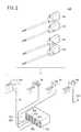
図2に示すように、マニピュレータシステム500は、選択的に種々の構成を採りうる。すなわち、操作部14は、バリエーションとして操作部14a〜14dが用意され、作業部16は、バリエーションとして作業部16a〜16dが用意されている。 As shown in FIG. 2, the
コントローラ514には、操作部14aに代えて操作部14b、14c及び14dを装着することができる。また、各操作部14a〜14dに対し、作業部16aに代えて作業部16b、16c及び16dを装着することができる。すなわち、術者は手技の種類や慣れ等に応じて操作部14a〜14d及び作業部16a〜16dを選択的に組み合わせて構成することができる。このうち、作業部16bは先端動作部12がはさみとなっている。作業部16cは先端動作部12がブレード型電気メスとなっている。作業部16dは先端動作部12がフック型電気メスとなっている。各作業部16a〜16dは、接続部15内のプーリ50a、50b及び50c(図1参照)は共通の構成となっている。 The
前記のとおり、コントローラ514は、3台のマニピュレータ10を同時に制御可能であることから、操作部14a〜14dのうちいずれか3つを第1ポート515a、第2ポート515b及び第3ポート515cに接続が可能である。 As described above, since the
次に、操作部14及び作業部16からなるマニピュレータ10について説明する。 Next, the
マニピュレータ10は、先端動作部12に生体の一部又は湾曲針等を把持して所定の処置を行うためのものであり、通常、把持鉗子やニードルドライバ(持針器)等とも呼ばれる。 The
図1及び図3に示すように、マニピュレータ10は、人手によって把持及び操作される操作部14と、該操作部14に対して着脱自在な作業部16とを有する。 As shown in FIGS. 1 and 3, the
以下の説明では、図1における幅方向をX方向、高さ方向をY方向及び、連結シャフト48の延在方向をZ方向と規定する。また、右方をX1方向、左方をX2方向、上方向をY1方向、下方向をY2方向、前方をZ1方向、後方をZ2方向と規定する。さらに、特に断りのない限り、これらの方向の記載はマニピュレータ10が中立姿勢である場合を基準として表すものとする。これらの方向は説明の便宜上のものであり、マニピュレータ10は任意の向きで(例えば、上下を反転させて)使用可能であることはもちろんである。 In the following description, the width direction in FIG. 1 is defined as the X direction, the height direction is defined as the Y direction, and the extending direction of the connecting
作業部16は、作業を行う先端動作部12と、操作部14のアクチュエータブロック(アクチュエータ部)30に対して接続される接続部15と、これらの先端動作部12と接続部15とを連接する長尺で中空の連結シャフト48とを有する。作業部16は、アクチュエータブロック30における所定の操作によって操作部14から離脱可能であって、洗浄、滅菌及びメンテナンス等を行うことができる。 The working
先端動作部12及び連結シャフト48は細径に構成されており、患者の腹部等に設けられた円筒形状のトラカール20から体腔22内に挿入可能であり、操作部14の操作により体腔22内において患部切除、把持、縫合及び結紮等の様々な手技を行うことができる。 The distal
操作部14は、人手によって把持されるグリップハンドル26と、該グリップハンドル26の上部から延在するブリッジ28と、該ブリッジ28の先端に接続されたアクチュエータブロック30とを有する。 The
図1に示すように、操作部14のグリップハンドル26は、ブリッジ28の端部からY2方向に向かって延在しており、人手によって把持されるのに適した長さであり、入力手段としてのトリガーレバー32と、複合入力部34と、スイッチ36とを有する。 As shown in FIG. 1, the grip handle 26 of the
ブリッジ28の上面(又は側面)における視認しやすい箇所にはLED(インジケータ)29が設けられている。LED29は、マニピュレータ10の制御状態を示すインジケータであり、操作者が容易に認識可能な大きさであり、且つ操作に支障がない程度に十分に小型軽量である。LED29は、ブリッジ28の上面における略中央部で、視認性のよい位置に設けられている。 An LED (indicator) 29 is provided at an easily visible position on the upper surface (or side surface) of the
グリップハンドル26の下端には、コントローラ514に接続されるケーブル61が設けられている。グリップハンドル26とケーブル61とは一体的に接続されている。グリップハンドル26とケーブル61とはコネクタにより接続されていてもよい。 A
複合入力部34は、先端動作部12に対してロール方向(軸回転方向)及びヨー方向(左右方向)の回転指令を与える複合的な入力手段であり、例えば軸回転に動作する第1入力手段によってロール方向指示を行い、横方向に動作する第2入力手段によってヨー方向指示を行うことができる。トリガーレバー32は、先端動作部12のグリッパ59(図1参照)の開閉指令を与える入力手段である。つまり、コントローラ514は、ロール軸、ヨー軸及びグリッパ軸に対応したモータ40、41、42の角度を示す内部信号を保持しており、複合入力部34及びトリガーレバー32の信号に基づいてこれらの内部信号を変化させてモータ40、41、42の角度が一致するように制御をしている。 The
スイッチ36は、マニピュレータ10の動作状態の有効又は無効を設定するための入力手段である。 The
図3及び図4に示すように、複合入力部34、トリガーレバー32には、それぞれ動作量を検出する入力センサ39a、39b、39cが設けられており、検出した動作信号をコントローラ514に供給する。これらのセンサの信号は、例えばアナログ信号であって、5Vの印加電圧に対して0.5V〜4.5Vの信号を発生してコントローラ514に供給する。コントローラ514では所定のプルアップ回路又はプルダウン回路を介してセンサの0.5V〜4.5Vの信号を入力しており、これらのセンサ信号(操作指令)の変化に基づいてコネクタ520の着脱を検出することができる。つまり、コネクタ520が抜かれたときには、プルアップ回路又はプルダウン回路により入力電圧が0V又は5Vになることから、コントローラ514は該コネクタ520が抜かれたことを検出可能である。 As shown in FIGS. 3 and 4, the
トリガーレバー32は、ブリッジ28のやや下方でZ1方向にやや突出したレバーであり、人差し指による操作が容易な位置に設けられている。 The
トリガーレバー32は、グリップハンドル26に対してアーム98により接続されており、該グリップハンドル26に対して進退するように構成されている。 The
スイッチ36はグリップハンドル26に対して進退する操作機構であって、トリガーレバー32とスイッチ36とはグリップハンドル26におけるZ1方向の面で、グリップハンドル26の長尺方向(Y方向)に並んで配置されている。スイッチ36はトリガーレバー32の直下(Y2方向)に設けられている。スイッチ36とトリガーレバー32との間には薄い板材130が設けられている。 The
スイッチ36はオルタネート式であって、一度手前(Z2方向)に引き込むことによってオン状態にロックされ、操作子36aは手前側の位置に保持される。再度スイッチ36を手前側に引き込むことによってオン状態は解除されてオフ状態となり、図示しない弾性体によって先端側(Z1方向)の位置に復帰する。このような操作により、スイッチ36は、オン状態又はオフ状態のいずれかに保持され、スイッチ36を押し続ける必要がない。したがって、オン状態とオフ状態との切り換え時だけスイッチ36の操作をすればよく、それ以外のときはトリガーレバー32の操作をすることができ、スイッチ36とトリガーレバー32とを併存させるのに好適である。 The
また、スイッチ36はオン状態とオフ状態では操作子36aの突き出し量が異なる構成であることから、操作子36aを目視し又は触れることによって状態を確認することができる。 Further, since the
スイッチ36は、モードの変更をさせるものである。モードの状態はLED29及び後述するポート番号ランプ560(図7参照)の点灯状態によっても示される。具体的には、LED29及びポート番号ランプ560は、動作モードのときには緑色点灯、停止モードのときには消灯となる。また、自動原点復帰動作時及びリセット動作時には緑の点滅となり、アラーム発生時には赤の点滅となる。 The
これらのモード及び動作はスイッチ36の操作によって変更される。つまり、コントローラ514は、スイッチ36の状態を読み込み、オン状態であるときに動作モードとし、オン状態からオフ状態に切り換わったときに自動原点復帰動作としてモータ40、41、42を所定の原点に戻し、原点に戻った後に停止モードとする。 These modes and operations are changed by operating the
動作モードとは、操作部14の操作指令を有効にしてモータ40、41、42を駆動するモードである。停止モードは、操作部14の操作指令の有無に関わらずモータ40、41、42を停止させるモードである。また、リセット動作とは、後述する所定の操作がなされたときにモータ40、41、42を自動的に所定の原点に戻す動作である。自動原点復帰動作及びリセット動作は、操作指令の有無に関わらずモータ40、41、42を動作させることから、自動モードとして分類される。 The operation mode is a mode in which the operation command of the
これらのモード及び動作はコントローラ514によって区別されて制御され、LED29及びポート番号ランプ560の点灯状態が切り換えられる。 These modes and operations are distinguished and controlled by the
アクチュエータブロック30には先端動作部12が有する3自由度の機構に対応してモータ40、モータ41及びモータ42が連結シャフト48の延在方向に沿って並列して設けられている。これらのモータ40、41及び42は小型、細径であって、アクチュエータブロック30はコンパクトな扁平形状に構成されている。アクチュエータブロック30は、操作部14のZ1方向端部の下方に設けられている。また、モータ40、41及び42は、操作部14の操作に基づき、コントローラ514の作用下に回転をする。 The
モータ40、41及び42には、回転角度を検出することのできる角度センサ43、44及び45が設けられており、検出した角度信号はコントローラ514に供給される。角度センサ43、44及び45としては、例えばロータリエンコーダが用いられる。 The
作業部16は、アクチュエータブロック30に対して接続される接続部15と、該接続部15からZ1方向に向かって延在する中空の連結シャフト48とを有する。接続部15には、モータ40、41及び42の駆動軸に接続されるプーリ50a、プーリ50b及びプーリ50cが回転自在に設けられている。プーリ50a〜50cにはそれぞれカップリングが設けられている。 The working
プーリ50a、プーリ50b及びプーリ50cには、ワイヤ52、ワイヤ53及びワイヤ54が巻き掛けられており、連結シャフト48の中空部分48a(図5参照)を通って先端動作部12まで延在している。ワイヤ52、ワイヤ53及びワイヤ54はそれぞれ同種、同径のものを用いることができる。 A
作業部16は、アクチュエータブロック30における所定の操作によって操作部14から離脱可能であって、洗浄、滅菌及びメンテナンス等を行うことができる。また、作業部16は他の形式のものに交換可能であって、手技に応じて連結シャフト48の長さの異なるもの、又は先端動作部12の機構が異なるものを装着することができる。 The working
作業部16は、操作部14に対して着脱自在であり、プーリ50a、50b及び50cの中心穴に対して、モータ40、41及び42の回転軸40a、41a及び42aが嵌合するように構成されている。プーリ50a、50b及び50cのY2方向下端にはそれぞれ十字状の結合凸部が設けられ、回転軸40a、41a及び42aには十字状の結合凹部が設けられている。結合凸部と結合凹部は互いに係合可能に形成されており、モータ40、41及び42の回転がプーリ50a、50b及び50cに対して確実に伝達される。これらの係合部は十字形状に限られない。 The working
接続部15には、作業部を個体識別することのできるIDを保持するID保持部104が設けられている。 The
ID保持部104は、例えばRFID(Radio Frequency Identification)等の無線式、バーコード若しくはマトリックス型二次元コード等の光学式等の非接触検出式、又は小突起列等の接触式で構成するとよい。 The
作業部16にRFID等のように書き込み可能な記憶媒体を用いる場合、製造日、使用開始日、最終使用日、メンテナンス期限日等のタイムスタンプやシリアルナンバー、使用回数上限、位相修正値(又は原点修正値)等の固有情報を都度記憶させてもよい。このような情報は、コントローラ514で読み込み動作状態表示部530(図1参照)に表示させ、又は所定の判断を行って注意又は警告を発させるとよい。 When a writable storage medium such as RFID is used for the working
ID保持部104の保持するIDは、作業部16a〜16d毎に識別が可能なように異なる値が付与されている。 Different values are assigned to the IDs held by the
ところで、ID保持部104は直接的な通電の必要がなく、接続部15及び作業部16には電気的接点が存在していない。したがって、操作部14から取り外した作業部16は洗浄、滅菌等を容易に行うことができる。つまり、モータやスイッチ、センサ等の電気機器をすべて操作部14側に配し、連結シャフト48及び先端動作部12からなる機械構成部品のみからなるものを作業部16側に配することで洗浄性を向上させている。作業部16と操作部14では汚れ具合、汚れ種類、洗浄方法が異なり、異なるメンテナンスが行われるため、離脱可能にすることが好適である。 By the way, the
操作部14は、接続された作業部16のID保持部104における情報を読取ってコントローラ514に供給するID中継部106を有する。ID中継部106は、例えばRFID用の送受信回路又はフォトカプラー等により構成される。 The
磁気、光又は電波方式を用いると、ID保持部104はID中継部106に対して非接触でIDを伝達することができ、ID保持部104及びID中継部106の耐久性が高く、汚れが少なく、しかも清掃、洗浄が容易となる。 When the magnetic, optical, or radio wave system is used, the
接続部15を操作部14から取り外す場合には、アクチュエータブロック30の両側面に設けられたレバー206を押してそれぞれ外方に開くように傾動させ、該レバー206の楔部206aを、接続部15の両側面に設けられた係合片200から解放する。これにより接続部15を操作部14から上方(Y1方向)に引き抜き、取り外しが可能となる。アクチュエータブロック30の上面には3本のアライメントピン212が設けられており、接続部15に設けられた嵌合孔202に嵌合することにより該接続部15を安定して保持可能である。接続部15を操作部14に取り付ける場合には、3本のアライメントピン212がそれぞれ嵌合孔202に嵌合するように合わせて、接続部15を下方(Y2方向)に押し下げる。これにより、レバー206は一旦外方に拡がり、その後原位置に戻ることにより係合片200に係合して、接続が完了する。 When removing the
接続部15が載置されるアクチュエータブロック30の上面30bにおいて、Z2方向の端部近傍には、接続部15の有無を検出する作業部検出手段107が設けられている。作業部検出手段107は、対向する位置に設けられた投光器107aと受光器107bとからなり、該投光器107aと該受光器107bとの間に接続部15の後端の一部が挿入されて遮光することにより該接続部15が装着されたことを検出できる。投光器107aと受光器107bは、X方向に対向する向きで且つ近接した位置に設けられている。投光器107aは例えばLEDであり、受光器107bは例えばフォトダイオードである。 On the
図5及び図6に示すように、先端動作部12はY方向の第1回転軸Oyを中心にして、それよりも先の部分がヨー方向に回動する第1自由度の機構(傾動機構、ピボット軸)と、第2回転軸Orを中心にしてロール方向に回動する第2自由度の機構(ロール回転機構)と、第3回転軸Ogを中心として先端のグリッパ59を開閉させる第3自由度とを有する合計3自由度の機構となっている。 As shown in FIGS. 5 and 6, the distal
第1自由度の機構である第1回転軸Oyは、連結シャフト48の基端側から先端側に延在する軸線Cと非平行に回動可能に設定するとよい。第2自由度の機構である第2回転軸Orは先端動作部12における先端部(つまりグリッパ59)の延在方向の軸線を中心として回動可能な機構とし、先端部をロール回転可能に設定するとよい。 The first rotation axis Oy, which is a mechanism having a first degree of freedom, may be set so as to be rotatable in a non-parallel manner with the axis C extending from the proximal end side to the distal end side of the connecting
先端動作部12は、ワイヤ52、ワイヤ53及びワイヤ54によって駆動され、各ワイヤ52、53及び54は、それぞれ対応する筒体60c、60b、60aに巻き掛けられている。 The distal
先端動作部12では、ワイヤ52及び54の作用下に歯車51及び55が回転し、図示しないフェイスギアを回転させることによって先端部をロール方向に回転させることができる。また、ワイヤ54の作用下に歯車51が回転し、ファイスギア57及び歯車58を介してグリッパ59を開閉させることができる。さらに、ワイヤ52、53、54の作用下に主軸部材62を介して先端部をヨー方向に回転させることができる。 In the distal
次に、コントローラ514について図7〜図9を参照しながら説明する。 Next, the
図7に示すように、コントローラ514の正面には、動作状態表示部530、電源情報表示部532、アラーム部534、アクティべートリセット部536、第1ポート515a、第2ポート515b、及び第3ポート515cが設けられている。 As shown in FIG. 7, on the front of the
動作状態表示部530は、術者や手術に携わる助手等が操作状態の確認が容易となるようにマニピュレータ10の動作状態や所定の対応指示を表示する液晶表示画面を有する。 The operation
電源情報表示部532は、電源スイッチ540と、電源ランプ542と、チャージングランプ544と、外部電源警報ランプ546と、バッテリ充電表示ランプ548とを有する。 The power
電源スイッチ540は、マニピュレータシステム500全体の電源の入切を行うスイッチである。電源ランプ542は電源が入っているときに点灯し、切れているときに消灯する。チャージングランプ544は、バッテリ112a(図9参照)に対してチャージが行われているときに点灯する。外部電源警報ランプ546は、外部電源119が非供給となったときに点灯する。バッテリ充電表示ランプ548は、バッテリ112aの充電量にしたがって点灯数、若しくは点灯色を変化させて電力残量を表示するものである。 The
アラーム部534は、アラームランプ550と、アラーム音停止スイッチ552とを有する。アラームランプ550は、アラームが発生したときに点灯するランプであり、別に設けられるアラームブザーのブザー音と同期して点灯する。アラーム音停止スイッチ552は、アラームブザーのブザー音を必要に応じて停止させるときに押すスイッチである。 The
アクティベートリセット部536は、アクティベートリセットスイッチ(第1リセットスイッチ)554と、リセットインディケートランプ556とを有する。リセットインディケートランプ556は、マニピュレータ10の各モータ40、41、42を所定の原点に強制復帰させるリセット動作の実行を行うべきタイミングにおいて点灯する。アクティベートリセットスイッチ554は、リセットインディケートランプ556が点灯しているときに押すことにより、リセット動作の第1回目の指示をするためのスイッチである。 The
第1ポート515aは、ポート番号ランプ560と、3つの作業部種別ランプ562、564及び566と、操作部14の接続確認ランプ568と、リセットスイッチ(第2リセットスイッチ)570と、レセプタクルコネクタ572とを有する。レセプタクルコネクタ572には前記のコネクタ520が接続される。 The
ポート番号ランプ560には番号「1」が印字されており、対応するマニピュレータ10が動作モードであるときに点灯する。前記のとおり、ポート番号ランプ560は、対応するマニピュレータ10が動作モードのときには点灯(例えば緑色)、停止モードのときには消灯となる。また、自動原点復帰動作時及びリセット動作時(つまり、自動モード)には点滅となり、アラーム発生時には赤の点滅となる。つまり、ポート番号ランプ560は、前記のLED29と同期して点灯状態が切り換わる。 The
作業部種別ランプ562、564及び566は、マニピュレータ10aにおいて操作部14に接続された作業部16の種類に応じていずれか1つが点灯し、その種類を表示するものである。作業部種別ランプ562は作業部16がはさみであるときに点灯し、作業部種別ランプ564は作業部16がグリッパであるときに点灯し、作業部種別ランプ566は作業部16が電気メスであるときに点灯する。 One of the work
接続確認ランプ568は、対応するレセプタクルコネクタ572にコネクタ520が正常に接続されたときに点灯する。リセットスイッチ570は、ランプ一体型のスイッチであり、対応するマニピュレータ10のリセット動作が必要なときであって、アクティベートリセットスイッチ554を押した後に点灯する。該リセットスイッチ570は、点灯しているときに押すことによって、対応するマニピュレータ10のモータ40、41、42が、コントローラ514の作用下に自動的にリセット動作を行う。リセット動作を行っている最中には、LED29及びポート番号ランプ560が点滅を行い、自動動作中であることを示す。 The
第2ポート515b及び第3ポート515cにおけるポート番号ランプ560には番号「2」及び「3」が印字されており、それ以外は第1ポート515aと同構成である。第2ポート515b及び第3ポート515cの各要素については、第1ポート515aの各要素と同符号を付して説明を省略する。 Numbers “2” and “3” are printed on the
第1ポート515a、第2ポート515b及び第3ポート515cはそれぞれ異なる色(例えば緑、黄及び青)の枠で囲まれており、識別が容易である。 The
コントローラ514におけるスイッチ及びランプには、それぞれの機能を示すシンボルマーク、文字若しくは略語が併記されている。これらのスイッチ及びランプは、メンブレン式であり、操作性、耐環境性に優れる。 Symbols, characters or abbreviations indicating the respective functions are written on the switches and lamps in the
次に、マニピュレータ10における各モータ40、41、42を所定の原点に強制的に復帰させたり、コントローラ514におけるモータ40、41、42の位置情報をリセットさせる動作の手順について図8を参照しながら説明する。このリセット動作は、モータ40、41、42を原点に戻さない非原点状態で作業部16を操作部14から取り外した場合や、非原点状態でコネクタ520を取り外した場合であって、操作者の判断により行われるものであって、アクティベートリセットスイッチ554及びリセットスイッチ570の双方が定められた手順によって操作されたときに実行される。なお、図8に示す処理は、3つの接続ポートのうち第1ポート515aに接続されたマニピュレータ10aのリセット動作について説明する。図8に示す処理は、基本的にはコントローラ514の作用下に行われる。 Next, referring to FIG. 8, an operation procedure for forcibly returning the
先ず、図8のステップS101において、第1ポート515aに接続されたマニピュレータ10aのモータ40、41、42の少なくとも1つが非原点状態で作業部16を操作部14から取り外した場合、又は非原点状態でコネクタ520を取り外した場合に、すなわち例えばマニピュレータ10aの操作部14から作業部16を取り外した場合、又はマニピュレータ10aに対応するコネクタ520を取り外した場合に、アラームを発生させる。つまり、アラームランプ550を点灯させ、ポート番号ランプ560を緑の点灯から赤の点滅に切り換え、ブザーを吹鳴させる。 First, in step S101 of FIG. 8, when at least one of the
作業部16を操作部14から取り外したか否かの判断は作業部検出手段107の信号に基づいて行う。コネクタ520がレセプタクルコネクタ572から取り外されたか否かの判断は、これらの複合入力部34から入力する操作指令の変化に基づいて行う。 The determination as to whether or not the working
また、動作状態表示部530には、例えば「ポート1の作業部を元に戻してください」という表示や、「ポート1のコネクタを元に戻してください」という表示をする。操作者はこれらの表示等に基づいて、対応の操作を行う。すなわち、コネクタ520が接続されていて作業部16が取り外されている場合には、取り外した作業部16を再装着し、コネクタ520が取り外されている場合には該コネクタを再装着する。その後、所定の操作を行って各モータ40、41、42を原点に復帰させる。 Further, the operation
ステップS102において、作業部16若しくはコネクタ520が元通りに装着若しくは接続された場合には、アラームを停止させる(ステップS103)。つまり、対応するアラームランプ550を消灯させ、ブザーを停止させ、ポート番号ランプ560及び操作部LED29の点灯色を緑に戻す。また、動作状態表示部530の表示を消し、又は正常復帰した旨の表示に切り換える。 In step S102, when the working
何らかの要因により、作業部16若しくはコネクタ520を元通りに装着若しくは接続することが困難であると判断される場合(例えば、作業部16若しくは操作部14に不具合が発生して使用に支障がある場合)にはステップS104に移る。 When it is determined that it is difficult to attach or connect the working
ステップS104において、動作状態表示部530に、「作業部若しくはコネクタを元に戻せない場合には『AR』スイッチを押してください」という表示をするとともに、アクティベートリセットスイッチ554が有効であることを示すためにリセットインディケートランプ556を点灯させる。 In step S104, the operation
ステップS105において、アクティベートリセットスイッチ554が押されたか否かを確認し、アクティベートリセットスイッチ554が押された場合にはステップS106へ移り、押されていない場合には該アクティベートリセットスイッチ554が押されるまで待機する。アクティベートリセットスイッチ554が押されるまでの間はリセットスイッチ570は無効になっている。アクティベートリセットスイッチ554が押された後、リセットインディケートランプ556を消灯する。 In step S105, it is confirmed whether or not the
ステップS106において、第1ポート515aに係るリセットスイッチ570を点灯させ、該リセットスイッチ570が有効になったことを示す。このとき、第2ポート及び第3ポートに係るリセットスイッチ570は消灯しており、操作者は第1ポート515aに係るリセットスイッチ570のみが有効であることを容易に理解できる。 In step S106, the
ステップS107において、第1ポート515aに係るリセットスイッチ570が押されたか否かを確認する。リセットスイッチ570が押された場合にはステップS108へ移り、押されていないときには該リセットスイッチ570が押されるまで待機する。 In step S107, it is confirmed whether or not the
なお、このステップS107及び前記のステップS105の待機の間においても、作業部16若しくはコネクタ520が元に戻せた場合には、図示を省略するが所定の割り込み処理等により、リセットインディケートランプ556を消灯させた後にステップS103に移ってアラームを解除してもよい。 Even during the standby of step S107 and step S105, if the working
ステップS108において、リセット動作を行う。すなわち、第1ポート515aに係るコネクタ520が接続されている場合には、作業部16が操作部14に対して装着されているか否かに拘わらず、モータ40、41、42を強制的に原点に復帰させる。このように、モータ40、41、42を強制的に原点に復帰させることにより、別の作業部16が操作部14に装着されたときに適切な制御が可能となる。リセット動作の後、リセットスイッチ570を消灯する。 In step S108, a reset operation is performed. That is, when the
第1ポート515aに係るコネクタ520が取り外されている場合には、コントローラ514に記憶させている該第1ポート515aに係る操作部14のモータ40、41、42の位置情報(角度を示す内部信号)が原点にリセットされる。位置情報はリセット前に所定の記憶部に退避、保存しておいてもよい。このように、モータ40、41、42の位置情報を強制的に原点に復帰させることにより、別の操作部14がコントローラ514に装着されたときに適切な制御が可能となる。 When the
リセットが終了すると、動作状態表示部530にその旨を表示する。なお、図8に示す処理は、後述するY15(図10参照)の非原点着脱エラーのタイミングにて行われる。 When the reset is completed, the fact is displayed on the operation
上述したように、本実施の形態に係る医療用のマニピュレータシステム500では、アクティベートリセットスイッチ554及びリセットスイッチ570の双方が定められた手順によって操作されたとき(つまり、リセットインディケートランプ556が点灯し、アクティベートリセットスイッチ554を押し、リセットスイッチ570が点灯し、その後リセットスイッチ570を押したとき)にアクチュエータを所定の原点に戻すリセット動作が行われ、該リセット動作が不用意に実行されることがない。アクティベートリセットスイッチ554及びリセットスイッチ570の操作手順は必ずしも上記のような2段階の手順に限らず、アクティベートリセットスイッチ554及びリセットスイッチ570の双方を操作するような別の手順であってもよく、例えば、双方を同時に押す操作が含まれていてもよい。 As described above, in the
また、上記の説明ではマニピュレータ10aの操作部14から作業部16を取り外した場合、又はコネクタ520を取り外した場合を例示したが、マニピュレータ10a〜10cの少なくとも1つの操作部14から作業部16を取り外した場合、又はマニピュレータ10a〜10cの少なくとも1つに対応するコネクタ520を取り外した場合も同様である。 Moreover, although the case where the working
また、点灯したリセットインディケートランプ556は、第1ポート515a〜第3ポート515cに係るエラーが解除された場合、リセットインディケートランプ556を消灯する。アラームランプ550についても同様である。 Also, the
コントローラ514では、リセットスイッチ570が3個設けられることにより、各マニピュレータ10a〜10c(図1参照)に対して個別のリセット動作が可能になり、好適である。また、アクティベートリセットスイッチ554は1つであり、無用にスイッチの数が増えることが防止でき、構成が簡便化されるとともに、操作性が向上する。 In the
アクティベートリセットスイッチ554及びリセットスイッチ570はコントローラ514に設けられており、マニピュレータ10側の構造が無用に複雑になることが防止でき、該マニピュレータ10が簡便且つ軽量となり、操作性が向上する。 The
コントローラ514は、3台のマニピュレータについて個別にエラーを検出する機能を有しており、例えば第1ポート515aでエラーが発生した場合には、ポート番号ランプの1番が赤で点滅し、アクティベートリセットスイッチ554が押されたときに、エラーの発生している第1ポート515aのリセットスイッチ570の発光手段を発光させる。したがって、操作が簡便となり、且つ誤操作が防止できる。 The
マニピュレータ10aにエラーが発生した場合、第2ポート515b及び第3ポート515cについてはコネクタ520の接続の有無に関わらずアラーム表示等を行わない。したがって、操作者は警報が発生したのが第1ポート515aに係るマニピュレータ10aであることを容易に認識できる。 When an error occurs in the
次に、コントローラ514の内部構成について図9を参照しながら説明する。なお、図9においては、煩雑とならないように第1ポート515aに係る部分を示し、第2ポート515b及び第3ポート515cに係る部分は省略する。第2ポート515b及び第3ポート515cに係る構成は、第1ポート515aに係る部分と一部が共通(例えば演算部110等)であり、一部が独立(例えばドライバ116等)に構成されている。図9においては、コントローラ514の表面(図7参照)の構成については省略している。 Next, the internal configuration of the
図9に示すように、コントローラ514は演算部110と、電源部112と、保護装置114と、ドライバ116とを有する。電源部112は、外部電源119から得られる電力を調整して各部に供給するとともに、バッテリ112aに充電を行い、外部電源119から電力が供給されない場合においても自動的にバッテリ112aからの電力供給へと切り換える機能を有しており、いわゆる無停電電源として作用する。バッテリ112aは内部の変圧整流器に対して、通常並列に接続される。 As illustrated in FIG. 9, the
保護装置114は、演算部110の演算周期情報、ドライバ情報、所定の停止指令等の各情報に基づいて、マニピュレータ10への電力を遮断する。保護装置114の作用下にドライバ116の電力を遮断することにより、マニピュレータ10の動作を直ちに停止させることができる。 The
演算部110は、角度センサ43、44、45、入力センサ39a、39b、39c、及びスイッチ36に接続されており、これらの各部から得られる信号に基づいてマニピュレータ10の動作を決定して、所定の指令信号をドライバ116に供給するとともに、動作状態表示部530に所定の状態量を表示させる。演算部110はLED29にも接続されており、該LED29の点灯状態の制御をする。さらに、演算部110は、コントローラ514の表面(図7参照)の、動作状態表示部530、電源情報表示部532、アラーム部534、アクティべートリセット部536、第1ポート515a、第2ポート515b、及び第3ポート515cの各スイッチ及びランプに接続されており、制御をする。演算部110は、CPU、ROM及びRAM等から構成されており、プログラムを読み込み実行することにより所定のソフトウェア処理を実行する。 The
ドライバ116は、モータ40、41及び42に接続されており、演算部110から得られる指令に基づいて該モータ40、41及び42を駆動する。ところで、これらのモータ40、41及び42の駆動系は、先ず、入力センサ39a、39b、39cに基づいて先端動作部に対する動作角度指令値を求め、該動作角度指令値と角度センサ43、44、45から得られる角度信号との偏差を求め、該偏差に基づいて所定の補償処理をして指令信号をドライバ116に供給している。したがって、これらの各モータ40、41及び42の駆動系は閉ループを形成している。 The
演算部110は、ID認識部120と、取外判断部121と、原点認識部122と、警告部124とを有する。ID認識部120は、ID保持部104のIDを認識する。取外判断部121はID認識部120で認識されたIDに基づいて、作業部16が操作部14より着脱された場合の同一性を判断する。 The
演算部110は、ID認識部120、原点認識部122及び操作部14の他の信号に基づいて条件判断を行い、所定条件下でドライバ116に対する電力供給を停止させ、モータ40、41及び42を非励磁とする。なお、モータ40、41及び42を非励磁にする手段としては、これ以外にもリレー等を用いて、該リレーによりドライバとコネクタ520との間を切り離すようにしてもよい。 The
トリガーレバー32及び複合入力部34(図1参照)には、人手による操作量を検出する入力センサ39a、39b、39c(ポテンショメータ等)に所定の電圧が印加され、該電圧の所定範囲が操作範囲として設定され、コントローラ514では、該センサから供給される電圧が所定範囲以外であることに基づいて操作部14が取り外されたことを認識する。これにより、トリガーレバー32及び複合入力部34を、操作量の入力手段と操作部14の取外認識手段に兼用することができる。 A predetermined voltage is applied to the
原点認識部122は、角度センサ43、44及び45の信号に基づいて先端動作部12が規定の原点又は非原点であることを認識する。警告部124は、原点認識部122から得られる信号に基づいて先端動作部12が非原点であると判断される場合で、ID中継部106から得られる信号に基づいて作業部16が操作部14から取り外されたと判断されるときに取外警告を発する。 The
また、警告部124は、取外警告を発しているとき、ID認識部120から得られるIDを監視し、作業部16a〜16dが再接続されたことを認識し、得られたIDが取り外し前に認識したIDと等しいときに取り外し警告を解除し、得られたIDが取り外し前に認識したIDと異なるときに誤接続警告を発し、動作状態表示部530に所定のメッセージを表示させる。 When the
取外警告及び誤接続警告は、音響・音声手段又は動作状態表示部530でのメッセージ表示により行うことができる。取外警告と誤接続警告とは容易に区別可能であることが好ましく、音響、音声手段で行う場合には例えば吹鳴インターバルや周波数の異なるブザー音とするとよい。 The removal warning and the erroneous connection warning can be performed by sound / audio means or message display on the operation
ID中継部106及びID認識部120により作業部16が取り外されていると判断される場合、又は、原点認識部122により先端動作部12が原点にあると判断される場合には、演算部110は、保護装置114の作用下にドライバ116に対する電力供給を停止させる。 When it is determined by the
次に、マニピュレータシステム500における作業部16の着脱動作時の作用について説明する。 Next, the operation at the time of attaching / detaching the working
図10では、最初にコントローラ514に対して操作部14aと作業部16aとからなるマニピュレータ10aが接続されているものとする。術者はこのマニピュレータ10aによって所定の手技を行う。つまり、マニピュレータ10aは、操作部14aの指令にしたがって作業部16aも動作する通常の操作状態となる(Y13)。 In FIG. 10, it is assumed that a
作業部16aを取り外し、別の作業部16b〜16dと交換する場合には、いったん操作部14aのモータ40、41、42の軸位置を原点へ復帰させ(Y14)原点認識部122により原点で停止したことを確認後、作業部16aを操作部14aから取り外して(Y12)別の作業部16b〜16dと交換する(Y11)。操作部14aが原点に復帰していることは、操作部14のLED29及びコントローラ514のパネル面等に設けられたポート番号ランプ560の消灯により確認することができる。 When the
また、仮に操作部14aのモータ40、41、42が非原点位置であるときに、作業部16aを操作部14aから取り外した場合(Y15)には、原点認識部122及びID認識部120の作用下に該状態が認識される。このような状態は非原点着脱エラーと定義され、警告部124の作用下に取外のアラームとしてアラームランプ550を点灯し、アラーム音を発するとともに動作状態表示部530に所定のメッセージを表示させ、術者に認識させる(図8参照)。 In addition, if the
非原点着脱エラー状態から通常の状態へ戻るためには、取り外した作業部16aを再度取り付ける(Y16)ことで、通常の操作状態に移行し、取り外した時点からの操作を継続できる。このとき、非原点着脱エラー及び取外警告は解除される。そして、モータ40、41、42及びプーリ50a〜50cの軸位置を原点へ復帰させて停止させれば前記のY14と同じ状態となり、取り外して別の作業部16b〜16dと交換することができる。 In order to return to the normal state from the non-origin attaching / detaching error state, the removed working
さらに、非原点着脱エラーの状態で、取り外した作業部16aとは異なる作業部16b〜16dを接続した場合(Y17)には、原点認識部122及びID認識部120の作用下に該状態が認識される。このような状態は再接続エラーと定義され、警告部124の作用下に誤接続警告を発し、術者に認識させる。 Further, when the working
この状態から、誤接続をした作業部16b〜16dを取り外すことで(Y18)、再接続エラー及び誤接続警告は解除され、非原点着脱エラーの状態へ戻り、取外警告が再度発せられる。 From this state, by removing the erroneously connected working
次に、このようなマニピュレータシステム500の作用を図11に基づいて説明する。マニピュレータシステム500は、コントローラ514の演算部110の統合的な制御作用下に動作し、基本的には図11に示すフローチャートに従った処理を行う。図11の処理は予め決められた制御周期にしたがって繰り返し実行される。以下の説明では、断りのない限りステップ番号順に処理が行われるものとする。 Next, the operation of such a
図11のステップS11において、操作部14の角度検出器及び駆動部モータの角度検出器の出力を演算部110にて読み取る。 In step S <b> 11 of FIG. 11, the
ステップS12において、指令入力手段やスイッチ36等の入力を演算部110で認識する。 In step S12, the
ステップS13において、演算部110による認識結果をもとにマニピュレータ10の制御モードを決定する。 In step S <b> 13, the control mode of the
ステップS14において、判定された制御モードにしたがって動作方式の判別とモータ40、41及び42の目標値を生成する。ここで制御モードとは、予め決められた動作を自動で実行する自動制御モードや、操作部14の操作にしたがって作業部16aを動作させるマスタスレーブ制御モードをいう。動作方式とは、制御モードの切り換えにおいて確実に動作をつなげるための、加速動作、減速動作、等速動作、停止動作等の動作方式をいう。 In step S14, the operation method is determined and target values for the
ステップS15において、生成された制御目標値と先に読み取った角度センサ43、44及び45の信号とからPID制御等の制御演算によってモータ出力を算出しドライバ116へ出力する。 In step S15, a motor output is calculated by control calculation such as PID control from the generated control target value and the signals of the
ステップS16において、定義された種々の条件と角度センサ43、44及び45等で読み取った状態とを比較し、状態判別を行う。 In step S16, various defined conditions are compared with the states read by the
ステップS17において、判別された結果に基づき、コントローラ514に装備されたランプへ出力を行う。 In step S17, based on the determined result, an output is performed to a lamp equipped in the
上記の例では、接続ポートが3つあるマニピュレータシステム500について述べたが、接続ポートは4つ以上設けてもよい。腹腔鏡下手術においては、3又は4以上のマニピュレータを用いる場合もあり、又は一度に2本しか用いない場合でも予備や次の手技用の準備として設けておくことが好適だからである。 In the above example, the
また、2以上のマニピュレータを1つのコントローラ514で制御することにより、演算部110等が共用化されて消費電力の抑制効果が大きい。 Further, by controlling two or more manipulators with one
本発明に係る医療用マニピュレータシステムは、上述の実施の形態に限らず、本発明の要旨を逸脱することなく、種々の構成を採り得ることはもちろんである。 Of course, the medical manipulator system according to the present invention is not limited to the above-described embodiment, and various configurations can be adopted without departing from the gist of the present invention.
10…マニピュレータ 14…操作部
16…作業部 34…複合入力部
28…ブリッジ 29…LED(インジケータ)
30…アクチュエータブロック 32…トリガーレバー
36…スイッチ 40、41、42…モータ
40a、41a、42a…回転軸 43、44、45…角度センサ
48…連結シャフト 50a〜50c…プーリ
104…保持部 106…中継部
110…演算部 500…医療用のマニピュレータシステム
514…コントローラ 515a〜515c…ポート520…コネクタ
530…動作状態表示器 534…アラーム部
536…アクティベートリセット部 550…アラームランプ
554…アクティベートリセットスイッチ(第1リセットスイッチ)
556…リセットインディケートランプ 560…ポート番号ランプ
562、564、566…作業部種別ランプ
570…リセットスイッチ(第2リセットスイッチ)DESCRIPTION OF
DESCRIPTION OF
556 ...
Claims (6)
Translated fromJapanese前記マニピュレータは、
アクチュエータと、人手によって把持されるグリップハンドルと、操作指令を入力する入力部とを備える操作部と、
前記アクチュエータに対して着脱自在で、シャフトの先端に前記アクチュエータに連動して前記シャフトの軸と非平行なピボット軸を基準として回動する先端動作部を備える作業部と、
前記操作部に対する前記作業部の有無を示す信号を前記制御部に供給する作業部検出手段と、
を有し、
前記制御部は、前記作業部が前記操作部から取り外されたときで、前記アクチュエータが非原点であるときに警報を発し、前記第1リセットスイッチ及び前記第2リセットスイッチの双方が定められた手順によって操作されたときに前記アクチュエータを原点に戻すリセット動作を行うことを特徴とする医療用マニピュレータシステム。A medical manipulator system having a manipulator, a controller, a first reset switch, and a second reset switch,
The manipulator
An operation unit including an actuator, a grip handle gripped by a hand, and an input unit for inputting an operation command;
A working unit that is detachable with respect to the actuator and includes a tip operating unit that rotates at the tip of a shaft with a pivot axis that is non-parallel to the axis of the shaft linked to the actuator;
Working unit detection means for supplying a signal indicating the presence or absence of the working unit to the operation unit to the control unit;
Have
The control unit issues a warning when the working unit is removed from the operation unit and the actuator is at a non-origin, and both the first reset switch and the second reset switch are determined. A medical manipulator system that performs a resetting operation to return the actuator to the origin when operated by.
前記マニピュレータは、
アクチュエータと、人手によって把持されるグリップハンドルと、操作指令を入力する入力部とを備え、前記制御部にコネクタで接続された操作部と、
前記アクチュエータに対して着脱自在で、シャフトの先端に前記アクチュエータに連動して前記シャフト軸と非平行なピボット軸を基準として回動する先端動作部を備える作業部と、
を有し、
前記制御部は、前記操作指令の変化に基づいて前記コネクタの着脱を検出し、前記コネクタが取り外されたときで、前記アクチュエータが非原点であるときに警報を発し、前記第1リセットスイッチ及び前記第2リセットスイッチの双方が定められた手順によって操作されたときに前記アクチュエータの角度を示す内部信号を原点に戻すリセット動作を行うことを特徴とする医療用マニピュレータシステム。A medical manipulator system having a manipulator, a controller, a first reset switch, and a second reset switch,
The manipulator
An actuator, a grip handle gripped by a hand, an input unit for inputting an operation command, and an operation unit connected to the control unit by a connector;
A working unit that is detachable with respect to the actuator and includes a distal end operating unit that rotates at a distal end of a shaft on the basis of a pivot axis that is not parallel to the shaft axis in conjunction with the actuator;
Have
The control unit detects attachment / detachment of the connector based on a change in the operation command, issues an alarm when the connector is removed, and the actuator is at a non-origin, and the first reset switch and the A medical manipulator system that performs a reset operation for returning an internal signal indicating an angle of the actuator to an origin when both of the second reset switches are operated by a predetermined procedure.
前記制御部は、1台でN個の前記マニピュレータの制御が可能であり、
前記第1リセットスイッチはN個の前記マニピュレータに共通で1つ設けられ、
前記第2リセットスイッチは前記マニピュレータに対応したN個が設けられていることを特徴とする医療用マニピュレータシステム。The medical manipulator system according to claim 1 or 2,
The control unit can control the N manipulators with one unit,
The first reset switch is provided in common for the N manipulators,
The second reset switch is provided with N pieces corresponding to the manipulator, and the medical manipulator system.
前記第1リセットスイッチ及び前記第2リセットスイッチは前記制御部に設けられていることを特徴とする医療用マニピュレータシステム。The medical manipulator system according to any one of claims 1 to 3,
The medical manipulator system, wherein the first reset switch and the second reset switch are provided in the control unit.
前記第2リセットスイッチは発光手段を有し、
前記制御部は、N個の前記マニピュレータについて個別に前記作業部の着脱と前記アクチュエータの角度を検出する機能を有し、前記第1リセットスイッチが押されたときに、前記制御部は前記アクチュエータが非原点で前記作業部が取り外された前記マニピュレータに対応した前記第2リセットスイッチの前記発光手段を発光させ、発光をしている前記第2リセットスイッチを押した後に、対応する前記マニピュレータに対してリセット動作を行うことを特徴とする医療用マニピュレータシステム。The medical manipulator system according to claim 1,
The second reset switch has light emitting means,
The control unit has a function to detect attachment / detachment of the working unit and an angle of the actuator individually for the N manipulators, and when the first reset switch is pressed, the control unit The light emitting means of the second reset switch corresponding to the manipulator with the working unit removed at a non-origin is made to emit light, and after pressing the second reset switch emitting light, the corresponding manipulator A medical manipulator system characterized by performing a reset operation.
前記第2リセットスイッチは発光手段を有し、
前記制御部は、N個の前記マニピュレータについて個別にコネクタの着脱と前記アクチュエータの角度を検出する機能を有し、前記第1リセットスイッチが押されたときに、前記制御部は前記アクチュエータが非原点で前記コネクタが取り外された前記マニピュレータに対応した前記第2リセットスイッチの前記発光手段を発光させ、発光をしている前記第2リセットスイッチを押した後に、対応する前記マニピュレータに対してリセット動作を行うことを特徴とする医療用マニピュレータシステム。The medical manipulator system according to claim 2,
The second reset switch has light emitting means,
The control unit has a function of individually detecting attachment / detachment of a connector and an angle of the actuator for the N manipulators, and when the first reset switch is pressed, the control unit detects that the actuator is non-originating. The light emitting means of the second reset switch corresponding to the manipulator from which the connector has been removed is caused to emit light, and after pressing the second reset switch emitting light, the corresponding manipulator is reset. A medical manipulator system characterized by performing.
Priority Applications (2)
| Application Number | Priority Date | Filing Date | Title |
|---|---|---|---|
| JP2007227010AJP2009056164A (en) | 2007-08-31 | 2007-08-31 | Medical manipulator system |
| US12/201,065US8246608B2 (en) | 2007-08-31 | 2008-08-29 | Medical manipulator system |
Applications Claiming Priority (1)
| Application Number | Priority Date | Filing Date | Title |
|---|---|---|---|
| JP2007227010AJP2009056164A (en) | 2007-08-31 | 2007-08-31 | Medical manipulator system |
Publications (1)
| Publication Number | Publication Date |
|---|---|
| JP2009056164Atrue JP2009056164A (en) | 2009-03-19 |
Family
ID=40408666
Family Applications (1)
| Application Number | Title | Priority Date | Filing Date |
|---|---|---|---|
| JP2007227010APendingJP2009056164A (en) | 2007-08-31 | 2007-08-31 | Medical manipulator system |
Country Status (2)
| Country | Link |
|---|---|
| US (1) | US8246608B2 (en) |
| JP (1) | JP2009056164A (en) |
Cited By (17)
| Publication number | Priority date | Publication date | Assignee | Title |
|---|---|---|---|---|
| WO2010126129A1 (en)* | 2009-04-30 | 2010-11-04 | テルモ株式会社 | Medical manipulator |
| WO2010126128A1 (en)* | 2009-04-30 | 2010-11-04 | テルモ株式会社 | Medical manipulator |
| WO2010126127A1 (en)* | 2009-04-30 | 2010-11-04 | テルモ株式会社 | Medical manipulator |
| WO2013018926A1 (en)* | 2011-08-04 | 2013-02-07 | Olympus Corporation | Medical equipment |
| US9161772B2 (en) | 2011-08-04 | 2015-10-20 | Olympus Corporation | Surgical instrument and medical manipulator |
| US9218053B2 (en) | 2011-08-04 | 2015-12-22 | Olympus Corporation | Surgical assistant system |
| US9244523B2 (en) | 2011-08-04 | 2016-01-26 | Olympus Corporation | Manipulator system |
| US9244524B2 (en) | 2011-08-04 | 2016-01-26 | Olympus Corporation | Surgical instrument and control method thereof |
| US9423869B2 (en) | 2011-08-04 | 2016-08-23 | Olympus Corporation | Operation support device |
| US9477301B2 (en) | 2011-08-04 | 2016-10-25 | Olympus Corporation | Operation support device and assembly method thereof |
| US9519341B2 (en) | 2011-08-04 | 2016-12-13 | Olympus Corporation | Medical manipulator and surgical support apparatus |
| US9568992B2 (en) | 2011-08-04 | 2017-02-14 | Olympus Corporation | Medical manipulator |
| US9632573B2 (en) | 2011-08-04 | 2017-04-25 | Olympus Corporation | Medical manipulator and method of controlling the same |
| US9632577B2 (en) | 2011-08-04 | 2017-04-25 | Olympus Corporation | Operation support device and control method thereof |
| US9671860B2 (en) | 2011-08-04 | 2017-06-06 | Olympus Corporation | Manipulation input device and manipulator system having the same |
| US9851782B2 (en) | 2011-08-04 | 2017-12-26 | Olympus Corporation | Operation support device and attachment and detachment method thereof |
| US10881475B2 (en) | 2015-07-09 | 2021-01-05 | Kawasaki Jukogyo Kabushiki Kaisha | Surgical robot |
Families Citing this family (442)
| Publication number | Priority date | Publication date | Assignee | Title |
|---|---|---|---|---|
| US20070084897A1 (en) | 2003-05-20 | 2007-04-19 | Shelton Frederick E Iv | Articulating surgical stapling instrument incorporating a two-piece e-beam firing mechanism |
| US9060770B2 (en) | 2003-05-20 | 2015-06-23 | Ethicon Endo-Surgery, Inc. | Robotically-driven surgical instrument with E-beam driver |
| US11998198B2 (en) | 2004-07-28 | 2024-06-04 | Cilag Gmbh International | Surgical stapling instrument incorporating a two-piece E-beam firing mechanism |
| US9072535B2 (en) | 2011-05-27 | 2015-07-07 | Ethicon Endo-Surgery, Inc. | Surgical stapling instruments with rotatable staple deployment arrangements |
| US11890012B2 (en) | 2004-07-28 | 2024-02-06 | Cilag Gmbh International | Staple cartridge comprising cartridge body and attached support |
| US8215531B2 (en) | 2004-07-28 | 2012-07-10 | Ethicon Endo-Surgery, Inc. | Surgical stapling instrument having a medical substance dispenser |
| US7669746B2 (en) | 2005-08-31 | 2010-03-02 | Ethicon Endo-Surgery, Inc. | Staple cartridges for forming staples having differing formed staple heights |
| US11484312B2 (en) | 2005-08-31 | 2022-11-01 | Cilag Gmbh International | Staple cartridge comprising a staple driver arrangement |
| US10159482B2 (en) | 2005-08-31 | 2018-12-25 | Ethicon Llc | Fastener cartridge assembly comprising a fixed anvil and different staple heights |
| US11246590B2 (en) | 2005-08-31 | 2022-02-15 | Cilag Gmbh International | Staple cartridge including staple drivers having different unfired heights |
| US9237891B2 (en) | 2005-08-31 | 2016-01-19 | Ethicon Endo-Surgery, Inc. | Robotically-controlled surgical stapling devices that produce formed staples having different lengths |
| US7934630B2 (en) | 2005-08-31 | 2011-05-03 | Ethicon Endo-Surgery, Inc. | Staple cartridges for forming staples having differing formed staple heights |
| US20070106317A1 (en) | 2005-11-09 | 2007-05-10 | Shelton Frederick E Iv | Hydraulically and electrically actuated articulation joints for surgical instruments |
| US11793518B2 (en) | 2006-01-31 | 2023-10-24 | Cilag Gmbh International | Powered surgical instruments with firing system lockout arrangements |
| US11278279B2 (en) | 2006-01-31 | 2022-03-22 | Cilag Gmbh International | Surgical instrument assembly |
| US7753904B2 (en) | 2006-01-31 | 2010-07-13 | Ethicon Endo-Surgery, Inc. | Endoscopic surgical instrument with a handle that can articulate with respect to the shaft |
| US20110295295A1 (en) | 2006-01-31 | 2011-12-01 | Ethicon Endo-Surgery, Inc. | Robotically-controlled surgical instrument having recording capabilities |
| US20120292367A1 (en) | 2006-01-31 | 2012-11-22 | Ethicon Endo-Surgery, Inc. | Robotically-controlled end effector |
| US8186555B2 (en) | 2006-01-31 | 2012-05-29 | Ethicon Endo-Surgery, Inc. | Motor-driven surgical cutting and fastening instrument with mechanical closure system |
| US8820603B2 (en) | 2006-01-31 | 2014-09-02 | Ethicon Endo-Surgery, Inc. | Accessing data stored in a memory of a surgical instrument |
| US11224427B2 (en) | 2006-01-31 | 2022-01-18 | Cilag Gmbh International | Surgical stapling system including a console and retraction assembly |
| US7845537B2 (en) | 2006-01-31 | 2010-12-07 | Ethicon Endo-Surgery, Inc. | Surgical instrument having recording capabilities |
| US20110024477A1 (en) | 2009-02-06 | 2011-02-03 | Hall Steven G | Driven Surgical Stapler Improvements |
| US8708213B2 (en) | 2006-01-31 | 2014-04-29 | Ethicon Endo-Surgery, Inc. | Surgical instrument having a feedback system |
| US8992422B2 (en) | 2006-03-23 | 2015-03-31 | Ethicon Endo-Surgery, Inc. | Robotically-controlled endoscopic accessory channel |
| US8322455B2 (en) | 2006-06-27 | 2012-12-04 | Ethicon Endo-Surgery, Inc. | Manually driven surgical cutting and fastening instrument |
| US10568652B2 (en) | 2006-09-29 | 2020-02-25 | Ethicon Llc | Surgical staples having attached drivers of different heights and stapling instruments for deploying the same |
| US7506791B2 (en) | 2006-09-29 | 2009-03-24 | Ethicon Endo-Surgery, Inc. | Surgical stapling instrument with mechanical mechanism for limiting maximum tissue compression |
| US11980366B2 (en) | 2006-10-03 | 2024-05-14 | Cilag Gmbh International | Surgical instrument |
| US8684253B2 (en) | 2007-01-10 | 2014-04-01 | Ethicon Endo-Surgery, Inc. | Surgical instrument with wireless communication between a control unit of a robotic system and remote sensor |
| US8632535B2 (en) | 2007-01-10 | 2014-01-21 | Ethicon Endo-Surgery, Inc. | Interlock and surgical instrument including same |
| US11291441B2 (en) | 2007-01-10 | 2022-04-05 | Cilag Gmbh International | Surgical instrument with wireless communication between control unit and remote sensor |
| US8652120B2 (en) | 2007-01-10 | 2014-02-18 | Ethicon Endo-Surgery, Inc. | Surgical instrument with wireless communication between control unit and sensor transponders |
| US11039836B2 (en) | 2007-01-11 | 2021-06-22 | Cilag Gmbh International | Staple cartridge for use with a surgical stapling instrument |
| US20080169333A1 (en) | 2007-01-11 | 2008-07-17 | Shelton Frederick E | Surgical stapler end effector with tapered distal end |
| US7673782B2 (en) | 2007-03-15 | 2010-03-09 | Ethicon Endo-Surgery, Inc. | Surgical stapling instrument having a releasable buttress material |
| US8893946B2 (en) | 2007-03-28 | 2014-11-25 | Ethicon Endo-Surgery, Inc. | Laparoscopic tissue thickness and clamp load measuring devices |
| US8931682B2 (en) | 2007-06-04 | 2015-01-13 | Ethicon Endo-Surgery, Inc. | Robotically-controlled shaft based rotary drive systems for surgical instruments |
| US11564682B2 (en) | 2007-06-04 | 2023-01-31 | Cilag Gmbh International | Surgical stapler device |
| US7753245B2 (en) | 2007-06-22 | 2010-07-13 | Ethicon Endo-Surgery, Inc. | Surgical stapling instruments |
| US11849941B2 (en) | 2007-06-29 | 2023-12-26 | Cilag Gmbh International | Staple cartridge having staple cavities extending at a transverse angle relative to a longitudinal cartridge axis |
| US8758391B2 (en) | 2008-02-14 | 2014-06-24 | Ethicon Endo-Surgery, Inc. | Interchangeable tools for surgical instruments |
| US8636736B2 (en) | 2008-02-14 | 2014-01-28 | Ethicon Endo-Surgery, Inc. | Motorized surgical cutting and fastening instrument |
| US7866527B2 (en) | 2008-02-14 | 2011-01-11 | Ethicon Endo-Surgery, Inc. | Surgical stapling apparatus with interlockable firing system |
| US11986183B2 (en) | 2008-02-14 | 2024-05-21 | Cilag Gmbh International | Surgical cutting and fastening instrument comprising a plurality of sensors to measure an electrical parameter |
| US9179912B2 (en) | 2008-02-14 | 2015-11-10 | Ethicon Endo-Surgery, Inc. | Robotically-controlled motorized surgical cutting and fastening instrument |
| US7819298B2 (en) | 2008-02-14 | 2010-10-26 | Ethicon Endo-Surgery, Inc. | Surgical stapling apparatus with control features operable with one hand |
| US8573465B2 (en) | 2008-02-14 | 2013-11-05 | Ethicon Endo-Surgery, Inc. | Robotically-controlled surgical end effector system with rotary actuated closure systems |
| JP5410110B2 (en) | 2008-02-14 | 2014-02-05 | エシコン・エンド−サージェリィ・インコーポレイテッド | Surgical cutting / fixing instrument with RF electrode |
| US9585657B2 (en) | 2008-02-15 | 2017-03-07 | Ethicon Endo-Surgery, Llc | Actuator for releasing a layer of material from a surgical end effector |
| US11272927B2 (en) | 2008-02-15 | 2022-03-15 | Cilag Gmbh International | Layer arrangements for surgical staple cartridges |
| US11648005B2 (en) | 2008-09-23 | 2023-05-16 | Cilag Gmbh International | Robotically-controlled motorized surgical instrument with an end effector |
| US9386983B2 (en) | 2008-09-23 | 2016-07-12 | Ethicon Endo-Surgery, Llc | Robotically-controlled motorized surgical instrument |
| US8210411B2 (en) | 2008-09-23 | 2012-07-03 | Ethicon Endo-Surgery, Inc. | Motor-driven surgical cutting instrument |
| US9005230B2 (en) | 2008-09-23 | 2015-04-14 | Ethicon Endo-Surgery, Inc. | Motorized surgical instrument |
| US8608045B2 (en) | 2008-10-10 | 2013-12-17 | Ethicon Endo-Sugery, Inc. | Powered surgical cutting and stapling apparatus with manually retractable firing system |
| US8517239B2 (en) | 2009-02-05 | 2013-08-27 | Ethicon Endo-Surgery, Inc. | Surgical stapling instrument comprising a magnetic element driver |
| RU2525225C2 (en) | 2009-02-06 | 2014-08-10 | Этикон Эндо-Серджери, Инк. | Improvement of drive surgical suturing instrument |
| US8444036B2 (en) | 2009-02-06 | 2013-05-21 | Ethicon Endo-Surgery, Inc. | Motor driven surgical fastener device with mechanisms for adjusting a tissue gap within the end effector |
| US9675329B2 (en)* | 2009-07-27 | 2017-06-13 | Multi Scopic Instruments, Llc | Endoscopic surgical instrument |
| US8220688B2 (en) | 2009-12-24 | 2012-07-17 | Ethicon Endo-Surgery, Inc. | Motor-driven surgical cutting instrument with electric actuator directional control assembly |
| US8851354B2 (en) | 2009-12-24 | 2014-10-07 | Ethicon Endo-Surgery, Inc. | Surgical cutting instrument that analyzes tissue thickness |
| US9722334B2 (en) | 2010-04-07 | 2017-08-01 | Black & Decker Inc. | Power tool with light unit |
| US8783543B2 (en) | 2010-07-30 | 2014-07-22 | Ethicon Endo-Surgery, Inc. | Tissue acquisition arrangements and methods for surgical stapling devices |
| US9364233B2 (en) | 2010-09-30 | 2016-06-14 | Ethicon Endo-Surgery, Llc | Tissue thickness compensators for circular surgical staplers |
| US9386988B2 (en) | 2010-09-30 | 2016-07-12 | Ethicon End-Surgery, LLC | Retainer assembly including a tissue thickness compensator |
| US12213666B2 (en) | 2010-09-30 | 2025-02-04 | Cilag Gmbh International | Tissue thickness compensator comprising layers |
| US11925354B2 (en) | 2010-09-30 | 2024-03-12 | Cilag Gmbh International | Staple cartridge comprising staples positioned within a compressible portion thereof |
| US9629814B2 (en) | 2010-09-30 | 2017-04-25 | Ethicon Endo-Surgery, Llc | Tissue thickness compensator configured to redistribute compressive forces |
| US9788834B2 (en) | 2010-09-30 | 2017-10-17 | Ethicon Llc | Layer comprising deployable attachment members |
| US9016542B2 (en) | 2010-09-30 | 2015-04-28 | Ethicon Endo-Surgery, Inc. | Staple cartridge comprising compressible distortion resistant components |
| US9232941B2 (en) | 2010-09-30 | 2016-01-12 | Ethicon Endo-Surgery, Inc. | Tissue thickness compensator comprising a reservoir |
| US11812965B2 (en) | 2010-09-30 | 2023-11-14 | Cilag Gmbh International | Layer of material for a surgical end effector |
| US9351730B2 (en) | 2011-04-29 | 2016-05-31 | Ethicon Endo-Surgery, Llc | Tissue thickness compensator comprising channels |
| US10945731B2 (en) | 2010-09-30 | 2021-03-16 | Ethicon Llc | Tissue thickness compensator comprising controlled release and expansion |
| US11298125B2 (en) | 2010-09-30 | 2022-04-12 | Cilag Gmbh International | Tissue stapler having a thickness compensator |
| US8695866B2 (en) | 2010-10-01 | 2014-04-15 | Ethicon Endo-Surgery, Inc. | Surgical instrument having a power control circuit |
| US9510895B2 (en) | 2010-11-05 | 2016-12-06 | Ethicon Endo-Surgery, Llc | Surgical instrument with modular shaft and end effector |
| US10881448B2 (en) | 2010-11-05 | 2021-01-05 | Ethicon Llc | Cam driven coupling between ultrasonic transducer and waveguide in surgical instrument |
| US9375255B2 (en) | 2010-11-05 | 2016-06-28 | Ethicon Endo-Surgery, Llc | Surgical instrument handpiece with resiliently biased coupling to modular shaft and end effector |
| US9421062B2 (en) | 2010-11-05 | 2016-08-23 | Ethicon Endo-Surgery, Llc | Surgical instrument shaft with resiliently biased coupling to handpiece |
| US9072523B2 (en) | 2010-11-05 | 2015-07-07 | Ethicon Endo-Surgery, Inc. | Medical device with feature for sterile acceptance of non-sterile reusable component |
| US9782215B2 (en) | 2010-11-05 | 2017-10-10 | Ethicon Endo-Surgery, Llc | Surgical instrument with ultrasonic transducer having integral switches |
| US9730717B2 (en)* | 2011-02-03 | 2017-08-15 | Karl Storz Gmbh & Co. Kg | Medical manipulator system |
| AU2012250197B2 (en) | 2011-04-29 | 2017-08-10 | Ethicon Endo-Surgery, Inc. | Staple cartridge comprising staples positioned within a compressible portion thereof |
| US11207064B2 (en) | 2011-05-27 | 2021-12-28 | Cilag Gmbh International | Automated end effector component reloading system for use with a robotic system |
| US9554866B2 (en) | 2011-08-09 | 2017-01-31 | Covidien Lp | Apparatus and method for using a remote control system in surgical procedures |
| US20130046299A1 (en)* | 2011-08-18 | 2013-02-21 | John J. Newkirk | Intelligent electrosurgical electrode and tracking system |
| US9044230B2 (en) | 2012-02-13 | 2015-06-02 | Ethicon Endo-Surgery, Inc. | Surgical cutting and fastening instrument with apparatus for determining cartridge and firing motion status |
| US20130253480A1 (en) | 2012-03-22 | 2013-09-26 | Cory G. Kimball | Surgical instrument usage data management |
| US9364249B2 (en) | 2012-03-22 | 2016-06-14 | Ethicon Endo-Surgery, Llc | Method and apparatus for programming modular surgical instrument |
| MX358135B (en) | 2012-03-28 | 2018-08-06 | Ethicon Endo Surgery Inc | Tissue thickness compensator comprising a plurality of layers. |
| BR112014024098B1 (en) | 2012-03-28 | 2021-05-25 | Ethicon Endo-Surgery, Inc. | staple cartridge |
| JP6224070B2 (en) | 2012-03-28 | 2017-11-01 | エシコン・エンド−サージェリィ・インコーポレイテッドEthicon Endo−Surgery,Inc. | Retainer assembly including tissue thickness compensator |
| US9101358B2 (en) | 2012-06-15 | 2015-08-11 | Ethicon Endo-Surgery, Inc. | Articulatable surgical instrument comprising a firing drive |
| BR112014032776B1 (en) | 2012-06-28 | 2021-09-08 | Ethicon Endo-Surgery, Inc | SURGICAL INSTRUMENT SYSTEM AND SURGICAL KIT FOR USE WITH A SURGICAL INSTRUMENT SYSTEM |
| US20140005718A1 (en) | 2012-06-28 | 2014-01-02 | Ethicon Endo-Surgery, Inc. | Multi-functional powered surgical device with external dissection features |
| US20140001231A1 (en) | 2012-06-28 | 2014-01-02 | Ethicon Endo-Surgery, Inc. | Firing system lockout arrangements for surgical instruments |
| US9282974B2 (en) | 2012-06-28 | 2016-03-15 | Ethicon Endo-Surgery, Llc | Empty clip cartridge lockout |
| US11278284B2 (en) | 2012-06-28 | 2022-03-22 | Cilag Gmbh International | Rotary drive arrangements for surgical instruments |
| US9289256B2 (en) | 2012-06-28 | 2016-03-22 | Ethicon Endo-Surgery, Llc | Surgical end effectors having angled tissue-contacting surfaces |
| JP6290201B2 (en) | 2012-06-28 | 2018-03-07 | エシコン・エンド−サージェリィ・インコーポレイテッドEthicon Endo−Surgery,Inc. | Lockout for empty clip cartridge |
| US12383267B2 (en) | 2012-06-28 | 2025-08-12 | Cilag Gmbh International | Robotically powered surgical device with manually-actuatable reversing system |
| US9408606B2 (en) | 2012-06-28 | 2016-08-09 | Ethicon Endo-Surgery, Llc | Robotically powered surgical device with manually-actuatable reversing system |
| US20140207124A1 (en) | 2013-01-23 | 2014-07-24 | Ethicon Endo-Surgery, Inc. | Surgical instrument with selectable integral or external power source |
| RU2672520C2 (en) | 2013-03-01 | 2018-11-15 | Этикон Эндо-Серджери, Инк. | Hingedly turnable surgical instruments with conducting ways for signal transfer |
| BR112015021082B1 (en) | 2013-03-01 | 2022-05-10 | Ethicon Endo-Surgery, Inc | surgical instrument |
| US9629629B2 (en) | 2013-03-14 | 2017-04-25 | Ethicon Endo-Surgey, LLC | Control systems for surgical instruments |
| US9808244B2 (en) | 2013-03-14 | 2017-11-07 | Ethicon Llc | Sensor arrangements for absolute positioning system for surgical instruments |
| EP2977150B1 (en)* | 2013-03-18 | 2017-06-28 | Olympus Corporation | Manipulator |
| BR112015026109B1 (en) | 2013-04-16 | 2022-02-22 | Ethicon Endo-Surgery, Inc | surgical instrument |
| US9826976B2 (en) | 2013-04-16 | 2017-11-28 | Ethicon Llc | Motor driven surgical instruments with lockable dual drive shafts |
| US10064541B2 (en)* | 2013-08-12 | 2018-09-04 | Endochoice, Inc. | Endoscope connector cover detection and warning system |
| US9775609B2 (en) | 2013-08-23 | 2017-10-03 | Ethicon Llc | Tamper proof circuit for surgical instrument battery pack |
| MX369362B (en) | 2013-08-23 | 2019-11-06 | Ethicon Endo Surgery Llc | Firing member retraction devices for powered surgical instruments. |
| US9962161B2 (en) | 2014-02-12 | 2018-05-08 | Ethicon Llc | Deliverable surgical instrument |
| JP6462004B2 (en) | 2014-02-24 | 2019-01-30 | エシコン エルエルシー | Fastening system with launcher lockout |
| BR112016021943B1 (en) | 2014-03-26 | 2022-06-14 | Ethicon Endo-Surgery, Llc | SURGICAL INSTRUMENT FOR USE BY AN OPERATOR IN A SURGICAL PROCEDURE |
| US10004497B2 (en) | 2014-03-26 | 2018-06-26 | Ethicon Llc | Interface systems for use with surgical instruments |
| US12232723B2 (en) | 2014-03-26 | 2025-02-25 | Cilag Gmbh International | Systems and methods for controlling a segmented circuit |
| US20150272580A1 (en) | 2014-03-26 | 2015-10-01 | Ethicon Endo-Surgery, Inc. | Verification of number of battery exchanges/procedure count |
| US10013049B2 (en) | 2014-03-26 | 2018-07-03 | Ethicon Llc | Power management through sleep options of segmented circuit and wake up control |
| US10470768B2 (en) | 2014-04-16 | 2019-11-12 | Ethicon Llc | Fastener cartridge including a layer attached thereto |
| US20150297225A1 (en) | 2014-04-16 | 2015-10-22 | Ethicon Endo-Surgery, Inc. | Fastener cartridges including extensions having different configurations |
| BR112016023825B1 (en) | 2014-04-16 | 2022-08-02 | Ethicon Endo-Surgery, Llc | STAPLE CARTRIDGE FOR USE WITH A SURGICAL STAPLER AND STAPLE CARTRIDGE FOR USE WITH A SURGICAL INSTRUMENT |
| US10327764B2 (en) | 2014-09-26 | 2019-06-25 | Ethicon Llc | Method for creating a flexible staple line |
| CN106456176B (en) | 2014-04-16 | 2019-06-28 | 伊西康内外科有限责任公司 | Fastener Cartridge Including Extensions With Different Configurations |
| CN106456159B (en) | 2014-04-16 | 2019-03-08 | 伊西康内外科有限责任公司 | Fastener Cartridge Assembly and Nail Retainer Cover Arrangement |
| WO2016015233A1 (en)* | 2014-07-30 | 2016-02-04 | Covidien Lp | Surgical instruments capable of being selectively disassembled to facilitate replacement of disposable components and/or sterilization of reusable components |
| BR112017004361B1 (en) | 2014-09-05 | 2023-04-11 | Ethicon Llc | ELECTRONIC SYSTEM FOR A SURGICAL INSTRUMENT |
| US10135242B2 (en) | 2014-09-05 | 2018-11-20 | Ethicon Llc | Smart cartridge wake up operation and data retention |
| US11311294B2 (en) | 2014-09-05 | 2022-04-26 | Cilag Gmbh International | Powered medical device including measurement of closure state of jaws |
| US10105142B2 (en) | 2014-09-18 | 2018-10-23 | Ethicon Llc | Surgical stapler with plurality of cutting elements |
| CN107427300B (en) | 2014-09-26 | 2020-12-04 | 伊西康有限责任公司 | Surgical suture buttresses and auxiliary materials |
| US11523821B2 (en) | 2014-09-26 | 2022-12-13 | Cilag Gmbh International | Method for creating a flexible staple line |
| US10076325B2 (en) | 2014-10-13 | 2018-09-18 | Ethicon Llc | Surgical stapling apparatus comprising a tissue stop |
| US9924944B2 (en) | 2014-10-16 | 2018-03-27 | Ethicon Llc | Staple cartridge comprising an adjunct material |
| US10517594B2 (en) | 2014-10-29 | 2019-12-31 | Ethicon Llc | Cartridge assemblies for surgical staplers |
| US11141153B2 (en) | 2014-10-29 | 2021-10-12 | Cilag Gmbh International | Staple cartridges comprising driver arrangements |
| US9844376B2 (en) | 2014-11-06 | 2017-12-19 | Ethicon Llc | Staple cartridge comprising a releasable adjunct material |
| US10736636B2 (en) | 2014-12-10 | 2020-08-11 | Ethicon Llc | Articulatable surgical instrument system |
| US10188385B2 (en)* | 2014-12-18 | 2019-01-29 | Ethicon Llc | Surgical instrument system comprising lockable systems |
| US9943309B2 (en) | 2014-12-18 | 2018-04-17 | Ethicon Llc | Surgical instruments with articulatable end effectors and movable firing beam support arrangements |
| US9844375B2 (en) | 2014-12-18 | 2017-12-19 | Ethicon Llc | Drive arrangements for articulatable surgical instruments |
| US9844374B2 (en) | 2014-12-18 | 2017-12-19 | Ethicon Llc | Surgical instrument systems comprising an articulatable end effector and means for adjusting the firing stroke of a firing member |
| MX389118B (en) | 2014-12-18 | 2025-03-20 | Ethicon Llc | SURGICAL INSTRUMENT WITH AN ANVIL THAT CAN BE SELECTIVELY MOVED ON A DISCRETE, NON-MOBILE AXIS RELATIVE TO A STAPLE CARTRIDGE. |
| US10085748B2 (en) | 2014-12-18 | 2018-10-02 | Ethicon Llc | Locking arrangements for detachable shaft assemblies with articulatable surgical end effectors |
| US9987000B2 (en) | 2014-12-18 | 2018-06-05 | Ethicon Llc | Surgical instrument assembly comprising a flexible articulation system |
| CN107405161B (en)* | 2015-02-25 | 2020-05-26 | 奥林巴斯株式会社 | Mechanical arm |
| US10159483B2 (en) | 2015-02-27 | 2018-12-25 | Ethicon Llc | Surgical apparatus configured to track an end-of-life parameter |
| US11154301B2 (en) | 2015-02-27 | 2021-10-26 | Cilag Gmbh International | Modular stapling assembly |
| US10180463B2 (en) | 2015-02-27 | 2019-01-15 | Ethicon Llc | Surgical apparatus configured to assess whether a performance parameter of the surgical apparatus is within an acceptable performance band |
| US9993248B2 (en) | 2015-03-06 | 2018-06-12 | Ethicon Endo-Surgery, Llc | Smart sensors with local signal processing |
| JP2020121162A (en) | 2015-03-06 | 2020-08-13 | エシコン エルエルシーEthicon LLC | Time dependent evaluation of sensor data to determine stability element, creep element and viscoelastic element of measurement |
| US10617412B2 (en) | 2015-03-06 | 2020-04-14 | Ethicon Llc | System for detecting the mis-insertion of a staple cartridge into a surgical stapler |
| US10687806B2 (en) | 2015-03-06 | 2020-06-23 | Ethicon Llc | Adaptive tissue compression techniques to adjust closure rates for multiple tissue types |
| US9901342B2 (en) | 2015-03-06 | 2018-02-27 | Ethicon Endo-Surgery, Llc | Signal and power communication system positioned on a rotatable shaft |
| US10548504B2 (en) | 2015-03-06 | 2020-02-04 | Ethicon Llc | Overlaid multi sensor radio frequency (RF) electrode system to measure tissue compression |
| US9924961B2 (en) | 2015-03-06 | 2018-03-27 | Ethicon Endo-Surgery, Llc | Interactive feedback system for powered surgical instruments |
| US10245033B2 (en) | 2015-03-06 | 2019-04-02 | Ethicon Llc | Surgical instrument comprising a lockable battery housing |
| US9808246B2 (en) | 2015-03-06 | 2017-11-07 | Ethicon Endo-Surgery, Llc | Method of operating a powered surgical instrument |
| US10441279B2 (en) | 2015-03-06 | 2019-10-15 | Ethicon Llc | Multiple level thresholds to modify operation of powered surgical instruments |
| US10433844B2 (en) | 2015-03-31 | 2019-10-08 | Ethicon Llc | Surgical instrument with selectively disengageable threaded drive systems |
| US10835249B2 (en) | 2015-08-17 | 2020-11-17 | Ethicon Llc | Implantable layers for a surgical instrument |
| US10105139B2 (en) | 2015-09-23 | 2018-10-23 | Ethicon Llc | Surgical stapler having downstream current-based motor control |
| US10363036B2 (en) | 2015-09-23 | 2019-07-30 | Ethicon Llc | Surgical stapler having force-based motor control |
| US10238386B2 (en) | 2015-09-23 | 2019-03-26 | Ethicon Llc | Surgical stapler having motor control based on an electrical parameter related to a motor current |
| US10327769B2 (en) | 2015-09-23 | 2019-06-25 | Ethicon Llc | Surgical stapler having motor control based on a drive system component |
| US10299878B2 (en) | 2015-09-25 | 2019-05-28 | Ethicon Llc | Implantable adjunct systems for determining adjunct skew |
| US11890015B2 (en) | 2015-09-30 | 2024-02-06 | Cilag Gmbh International | Compressible adjunct with crossing spacer fibers |
| US10478188B2 (en) | 2015-09-30 | 2019-11-19 | Ethicon Llc | Implantable layer comprising a constricted configuration |
| US10980539B2 (en) | 2015-09-30 | 2021-04-20 | Ethicon Llc | Implantable adjunct comprising bonded layers |
| US10433846B2 (en) | 2015-09-30 | 2019-10-08 | Ethicon Llc | Compressible adjunct with crossing spacer fibers |
| US10368865B2 (en) | 2015-12-30 | 2019-08-06 | Ethicon Llc | Mechanisms for compensating for drivetrain failure in powered surgical instruments |
| US10292704B2 (en) | 2015-12-30 | 2019-05-21 | Ethicon Llc | Mechanisms for compensating for battery pack failure in powered surgical instruments |
| US10265068B2 (en) | 2015-12-30 | 2019-04-23 | Ethicon Llc | Surgical instruments with separable motors and motor control circuits |
| BR112018016098B1 (en) | 2016-02-09 | 2023-02-23 | Ethicon Llc | SURGICAL INSTRUMENT |
| US11213293B2 (en) | 2016-02-09 | 2022-01-04 | Cilag Gmbh International | Articulatable surgical instruments with single articulation link arrangements |
| US10413291B2 (en) | 2016-02-09 | 2019-09-17 | Ethicon Llc | Surgical instrument articulation mechanism with slotted secondary constraint |
| US11224426B2 (en) | 2016-02-12 | 2022-01-18 | Cilag Gmbh International | Mechanisms for compensating for drivetrain failure in powered surgical instruments |
| US10258331B2 (en) | 2016-02-12 | 2019-04-16 | Ethicon Llc | Mechanisms for compensating for drivetrain failure in powered surgical instruments |
| US10448948B2 (en) | 2016-02-12 | 2019-10-22 | Ethicon Llc | Mechanisms for compensating for drivetrain failure in powered surgical instruments |
| US10413297B2 (en) | 2016-04-01 | 2019-09-17 | Ethicon Llc | Surgical stapling system configured to apply annular rows of staples having different heights |
| US10617413B2 (en) | 2016-04-01 | 2020-04-14 | Ethicon Llc | Closure system arrangements for surgical cutting and stapling devices with separate and distinct firing shafts |
| US10456137B2 (en) | 2016-04-15 | 2019-10-29 | Ethicon Llc | Staple formation detection mechanisms |
| US10426467B2 (en) | 2016-04-15 | 2019-10-01 | Ethicon Llc | Surgical instrument with detection sensors |
| US10405859B2 (en) | 2016-04-15 | 2019-09-10 | Ethicon Llc | Surgical instrument with adjustable stop/start control during a firing motion |
| US10357247B2 (en) | 2016-04-15 | 2019-07-23 | Ethicon Llc | Surgical instrument with multiple program responses during a firing motion |
| US10492783B2 (en) | 2016-04-15 | 2019-12-03 | Ethicon, Llc | Surgical instrument with improved stop/start control during a firing motion |
| US11179150B2 (en) | 2016-04-15 | 2021-11-23 | Cilag Gmbh International | Systems and methods for controlling a surgical stapling and cutting instrument |
| US11607239B2 (en) | 2016-04-15 | 2023-03-21 | Cilag Gmbh International | Systems and methods for controlling a surgical stapling and cutting instrument |
| US10335145B2 (en) | 2016-04-15 | 2019-07-02 | Ethicon Llc | Modular surgical instrument with configurable operating mode |
| US10828028B2 (en) | 2016-04-15 | 2020-11-10 | Ethicon Llc | Surgical instrument with multiple program responses during a firing motion |
| US20170296173A1 (en) | 2016-04-18 | 2017-10-19 | Ethicon Endo-Surgery, Llc | Method for operating a surgical instrument |
| US10363037B2 (en) | 2016-04-18 | 2019-07-30 | Ethicon Llc | Surgical instrument system comprising a magnetic lockout |
| US11317917B2 (en) | 2016-04-18 | 2022-05-03 | Cilag Gmbh International | Surgical stapling system comprising a lockable firing assembly |
| US10500000B2 (en) | 2016-08-16 | 2019-12-10 | Ethicon Llc | Surgical tool with manual control of end effector jaws |
| US10485543B2 (en) | 2016-12-21 | 2019-11-26 | Ethicon Llc | Anvil having a knife slot width |
| US11419606B2 (en) | 2016-12-21 | 2022-08-23 | Cilag Gmbh International | Shaft assembly comprising a clutch configured to adapt the output of a rotary firing member to two different systems |
| JP7010956B2 (en) | 2016-12-21 | 2022-01-26 | エシコン エルエルシー | How to staple tissue |
| US10898186B2 (en) | 2016-12-21 | 2021-01-26 | Ethicon Llc | Staple forming pocket arrangements comprising primary sidewalls and pocket sidewalls |
| US20180168625A1 (en) | 2016-12-21 | 2018-06-21 | Ethicon Endo-Surgery, Llc | Surgical stapling instruments with smart staple cartridges |
| MX2019007295A (en) | 2016-12-21 | 2019-10-15 | Ethicon Llc | Surgical instrument system comprising an end effector lockout and a firing assembly lockout. |
| US10813638B2 (en) | 2016-12-21 | 2020-10-27 | Ethicon Llc | Surgical end effectors with expandable tissue stop arrangements |
| US20180168615A1 (en) | 2016-12-21 | 2018-06-21 | Ethicon Endo-Surgery, Llc | Method of deforming staples from two different types of staple cartridges with the same surgical stapling instrument |
| CN110087565A (en) | 2016-12-21 | 2019-08-02 | 爱惜康有限责任公司 | Surgical stapling system |
| US10426471B2 (en) | 2016-12-21 | 2019-10-01 | Ethicon Llc | Surgical instrument with multiple failure response modes |
| JP6983893B2 (en) | 2016-12-21 | 2021-12-17 | エシコン エルエルシーEthicon LLC | Lockout configuration for surgical end effectors and replaceable tool assemblies |
| US10542982B2 (en)* | 2016-12-21 | 2020-01-28 | Ethicon Llc | Shaft assembly comprising first and second articulation lockouts |
| US10758229B2 (en) | 2016-12-21 | 2020-09-01 | Ethicon Llc | Surgical instrument comprising improved jaw control |
| US10582928B2 (en) | 2016-12-21 | 2020-03-10 | Ethicon Llc | Articulation lock arrangements for locking an end effector in an articulated position in response to actuation of a jaw closure system |
| US11134942B2 (en) | 2016-12-21 | 2021-10-05 | Cilag Gmbh International | Surgical stapling instruments and staple-forming anvils |
| US10973516B2 (en) | 2016-12-21 | 2021-04-13 | Ethicon Llc | Surgical end effectors and adaptable firing members therefor |
| US10695055B2 (en) | 2016-12-21 | 2020-06-30 | Ethicon Llc | Firing assembly comprising a lockout |
| US11090048B2 (en) | 2016-12-21 | 2021-08-17 | Cilag Gmbh International | Method for resetting a fuse of a surgical instrument shaft |
| JP7010957B2 (en) | 2016-12-21 | 2022-01-26 | エシコン エルエルシー | Shaft assembly with lockout |
| US10568625B2 (en) | 2016-12-21 | 2020-02-25 | Ethicon Llc | Staple cartridges and arrangements of staples and staple cavities therein |
| JP2020501815A (en) | 2016-12-21 | 2020-01-23 | エシコン エルエルシーEthicon LLC | Surgical stapling system |
| US10980536B2 (en) | 2016-12-21 | 2021-04-20 | Ethicon Llc | No-cartridge and spent cartridge lockout arrangements for surgical staplers |
| US10888321B2 (en) | 2017-06-20 | 2021-01-12 | Ethicon Llc | Systems and methods for controlling velocity of a displacement member of a surgical stapling and cutting instrument |
| USD879809S1 (en) | 2017-06-20 | 2020-03-31 | Ethicon Llc | Display panel with changeable graphical user interface |
| USD890784S1 (en) | 2017-06-20 | 2020-07-21 | Ethicon Llc | Display panel with changeable graphical user interface |
| US10881396B2 (en) | 2017-06-20 | 2021-01-05 | Ethicon Llc | Surgical instrument with variable duration trigger arrangement |
| US11653914B2 (en) | 2017-06-20 | 2023-05-23 | Cilag Gmbh International | Systems and methods for controlling motor velocity of a surgical stapling and cutting instrument according to articulation angle of end effector |
| US11071554B2 (en) | 2017-06-20 | 2021-07-27 | Cilag Gmbh International | Closed loop feedback control of motor velocity of a surgical stapling and cutting instrument based on magnitude of velocity error measurements |
| US10813639B2 (en) | 2017-06-20 | 2020-10-27 | Ethicon Llc | Closed loop feedback control of motor velocity of a surgical stapling and cutting instrument based on system conditions |
| US11090046B2 (en) | 2017-06-20 | 2021-08-17 | Cilag Gmbh International | Systems and methods for controlling displacement member motion of a surgical stapling and cutting instrument |
| US11382638B2 (en) | 2017-06-20 | 2022-07-12 | Cilag Gmbh International | Closed loop feedback control of motor velocity of a surgical stapling and cutting instrument based on measured time over a specified displacement distance |
| US10624633B2 (en) | 2017-06-20 | 2020-04-21 | Ethicon Llc | Systems and methods for controlling motor velocity of a surgical stapling and cutting instrument |
| US10646220B2 (en) | 2017-06-20 | 2020-05-12 | Ethicon Llc | Systems and methods for controlling displacement member velocity for a surgical instrument |
| US10779820B2 (en) | 2017-06-20 | 2020-09-22 | Ethicon Llc | Systems and methods for controlling motor speed according to user input for a surgical instrument |
| US11517325B2 (en) | 2017-06-20 | 2022-12-06 | Cilag Gmbh International | Closed loop feedback control of motor velocity of a surgical stapling and cutting instrument based on measured displacement distance traveled over a specified time interval |
| US10881399B2 (en) | 2017-06-20 | 2021-01-05 | Ethicon Llc | Techniques for adaptive control of motor velocity of a surgical stapling and cutting instrument |
| US10368864B2 (en) | 2017-06-20 | 2019-08-06 | Ethicon Llc | Systems and methods for controlling displaying motor velocity for a surgical instrument |
| US10390841B2 (en) | 2017-06-20 | 2019-08-27 | Ethicon Llc | Control of motor velocity of a surgical stapling and cutting instrument based on angle of articulation |
| US10327767B2 (en) | 2017-06-20 | 2019-06-25 | Ethicon Llc | Control of motor velocity of a surgical stapling and cutting instrument based on angle of articulation |
| US10980537B2 (en) | 2017-06-20 | 2021-04-20 | Ethicon Llc | Closed loop feedback control of motor velocity of a surgical stapling and cutting instrument based on measured time over a specified number of shaft rotations |
| US10307170B2 (en) | 2017-06-20 | 2019-06-04 | Ethicon Llc | Method for closed loop control of motor velocity of a surgical stapling and cutting instrument |
| USD879808S1 (en) | 2017-06-20 | 2020-03-31 | Ethicon Llc | Display panel with graphical user interface |
| US10856869B2 (en) | 2017-06-27 | 2020-12-08 | Ethicon Llc | Surgical anvil arrangements |
| US11266405B2 (en) | 2017-06-27 | 2022-03-08 | Cilag Gmbh International | Surgical anvil manufacturing methods |
| US10993716B2 (en) | 2017-06-27 | 2021-05-04 | Ethicon Llc | Surgical anvil arrangements |
| US11324503B2 (en) | 2017-06-27 | 2022-05-10 | Cilag Gmbh International | Surgical firing member arrangements |
| US10772629B2 (en) | 2017-06-27 | 2020-09-15 | Ethicon Llc | Surgical anvil arrangements |
| US11090049B2 (en) | 2017-06-27 | 2021-08-17 | Cilag Gmbh International | Staple forming pocket arrangements |
| US11246592B2 (en) | 2017-06-28 | 2022-02-15 | Cilag Gmbh International | Surgical instrument comprising an articulation system lockable to a frame |
| US10765427B2 (en) | 2017-06-28 | 2020-09-08 | Ethicon Llc | Method for articulating a surgical instrument |
| USD854151S1 (en) | 2017-06-28 | 2019-07-16 | Ethicon Llc | Surgical instrument shaft |
| US10716614B2 (en) | 2017-06-28 | 2020-07-21 | Ethicon Llc | Surgical shaft assemblies with slip ring assemblies with increased contact pressure |
| US11259805B2 (en) | 2017-06-28 | 2022-03-01 | Cilag Gmbh International | Surgical instrument comprising firing member supports |
| EP3420947B1 (en) | 2017-06-28 | 2022-05-25 | Cilag GmbH International | Surgical instrument comprising selectively actuatable rotatable couplers |
| USD869655S1 (en) | 2017-06-28 | 2019-12-10 | Ethicon Llc | Surgical fastener cartridge |
| US11484310B2 (en) | 2017-06-28 | 2022-11-01 | Cilag Gmbh International | Surgical instrument comprising a shaft including a closure tube profile |
| US10903685B2 (en) | 2017-06-28 | 2021-01-26 | Ethicon Llc | Surgical shaft assemblies with slip ring assemblies forming capacitive channels |
| US10211586B2 (en) | 2017-06-28 | 2019-02-19 | Ethicon Llc | Surgical shaft assemblies with watertight housings |
| US11564686B2 (en) | 2017-06-28 | 2023-01-31 | Cilag Gmbh International | Surgical shaft assemblies with flexible interfaces |
| USD851762S1 (en) | 2017-06-28 | 2019-06-18 | Ethicon Llc | Anvil |
| US10758232B2 (en) | 2017-06-28 | 2020-09-01 | Ethicon Llc | Surgical instrument with positive jaw opening features |
| USD906355S1 (en) | 2017-06-28 | 2020-12-29 | Ethicon Llc | Display screen or portion thereof with a graphical user interface for a surgical instrument |
| US10258418B2 (en) | 2017-06-29 | 2019-04-16 | Ethicon Llc | System for controlling articulation forces |
| US10398434B2 (en) | 2017-06-29 | 2019-09-03 | Ethicon Llc | Closed loop velocity control of closure member for robotic surgical instrument |
| US10932772B2 (en) | 2017-06-29 | 2021-03-02 | Ethicon Llc | Methods for closed loop velocity control for robotic surgical instrument |
| US11007022B2 (en) | 2017-06-29 | 2021-05-18 | Ethicon Llc | Closed loop velocity control techniques based on sensed tissue parameters for robotic surgical instrument |
| US10898183B2 (en) | 2017-06-29 | 2021-01-26 | Ethicon Llc | Robotic surgical instrument with closed loop feedback techniques for advancement of closure member during firing |
| US11304695B2 (en) | 2017-08-03 | 2022-04-19 | Cilag Gmbh International | Surgical system shaft interconnection |
| US11974742B2 (en) | 2017-08-03 | 2024-05-07 | Cilag Gmbh International | Surgical system comprising an articulation bailout |
| US11944300B2 (en) | 2017-08-03 | 2024-04-02 | Cilag Gmbh International | Method for operating a surgical system bailout |
| US11471155B2 (en) | 2017-08-03 | 2022-10-18 | Cilag Gmbh International | Surgical system bailout |
| USD907648S1 (en) | 2017-09-29 | 2021-01-12 | Ethicon Llc | Display screen or portion thereof with animated graphical user interface |
| US10743872B2 (en) | 2017-09-29 | 2020-08-18 | Ethicon Llc | System and methods for controlling a display of a surgical instrument |
| US10729501B2 (en) | 2017-09-29 | 2020-08-04 | Ethicon Llc | Systems and methods for language selection of a surgical instrument |
| US10765429B2 (en) | 2017-09-29 | 2020-09-08 | Ethicon Llc | Systems and methods for providing alerts according to the operational state of a surgical instrument |
| USD907647S1 (en) | 2017-09-29 | 2021-01-12 | Ethicon Llc | Display screen or portion thereof with animated graphical user interface |
| USD917500S1 (en) | 2017-09-29 | 2021-04-27 | Ethicon Llc | Display screen or portion thereof with graphical user interface |
| US11399829B2 (en) | 2017-09-29 | 2022-08-02 | Cilag Gmbh International | Systems and methods of initiating a power shutdown mode for a surgical instrument |
| US10796471B2 (en) | 2017-09-29 | 2020-10-06 | Ethicon Llc | Systems and methods of displaying a knife position for a surgical instrument |
| US11134944B2 (en) | 2017-10-30 | 2021-10-05 | Cilag Gmbh International | Surgical stapler knife motion controls |
| US11090075B2 (en) | 2017-10-30 | 2021-08-17 | Cilag Gmbh International | Articulation features for surgical end effector |
| US10842490B2 (en) | 2017-10-31 | 2020-11-24 | Ethicon Llc | Cartridge body design with force reduction based on firing completion |
| US10779903B2 (en) | 2017-10-31 | 2020-09-22 | Ethicon Llc | Positive shaft rotation lock activated by jaw closure |
| US10779826B2 (en) | 2017-12-15 | 2020-09-22 | Ethicon Llc | Methods of operating surgical end effectors |
| US11071543B2 (en) | 2017-12-15 | 2021-07-27 | Cilag Gmbh International | Surgical end effectors with clamping assemblies configured to increase jaw aperture ranges |
| US10828033B2 (en) | 2017-12-15 | 2020-11-10 | Ethicon Llc | Handheld electromechanical surgical instruments with improved motor control arrangements for positioning components of an adapter coupled thereto |
| US10743874B2 (en) | 2017-12-15 | 2020-08-18 | Ethicon Llc | Sealed adapters for use with electromechanical surgical instruments |
| US10743875B2 (en) | 2017-12-15 | 2020-08-18 | Ethicon Llc | Surgical end effectors with jaw stiffener arrangements configured to permit monitoring of firing member |
| US11033267B2 (en) | 2017-12-15 | 2021-06-15 | Ethicon Llc | Systems and methods of controlling a clamping member firing rate of a surgical instrument |
| US10869666B2 (en) | 2017-12-15 | 2020-12-22 | Ethicon Llc | Adapters with control systems for controlling multiple motors of an electromechanical surgical instrument |
| US10687813B2 (en) | 2017-12-15 | 2020-06-23 | Ethicon Llc | Adapters with firing stroke sensing arrangements for use in connection with electromechanical surgical instruments |
| US10779825B2 (en) | 2017-12-15 | 2020-09-22 | Ethicon Llc | Adapters with end effector position sensing and control arrangements for use in connection with electromechanical surgical instruments |
| US11197670B2 (en) | 2017-12-15 | 2021-12-14 | Cilag Gmbh International | Surgical end effectors with pivotal jaws configured to touch at their respective distal ends when fully closed |
| US10966718B2 (en) | 2017-12-15 | 2021-04-06 | Ethicon Llc | Dynamic clamping assemblies with improved wear characteristics for use in connection with electromechanical surgical instruments |
| US11006955B2 (en) | 2017-12-15 | 2021-05-18 | Ethicon Llc | End effectors with positive jaw opening features for use with adapters for electromechanical surgical instruments |
| US10729509B2 (en) | 2017-12-19 | 2020-08-04 | Ethicon Llc | Surgical instrument comprising closure and firing locking mechanism |
| USD910847S1 (en) | 2017-12-19 | 2021-02-16 | Ethicon Llc | Surgical instrument assembly |
| US11045270B2 (en) | 2017-12-19 | 2021-06-29 | Cilag Gmbh International | Robotic attachment comprising exterior drive actuator |
| US10835330B2 (en) | 2017-12-19 | 2020-11-17 | Ethicon Llc | Method for determining the position of a rotatable jaw of a surgical instrument attachment assembly |
| US10716565B2 (en) | 2017-12-19 | 2020-07-21 | Ethicon Llc | Surgical instruments with dual articulation drivers |
| US11020112B2 (en) | 2017-12-19 | 2021-06-01 | Ethicon Llc | Surgical tools configured for interchangeable use with different controller interfaces |
| US11076853B2 (en) | 2017-12-21 | 2021-08-03 | Cilag Gmbh International | Systems and methods of displaying a knife position during transection for a surgical instrument |
| US12336705B2 (en) | 2017-12-21 | 2025-06-24 | Cilag Gmbh International | Continuous use self-propelled stapling instrument |
| US11179151B2 (en) | 2017-12-21 | 2021-11-23 | Cilag Gmbh International | Surgical instrument comprising a display |
| US11311290B2 (en) | 2017-12-21 | 2022-04-26 | Cilag Gmbh International | Surgical instrument comprising an end effector dampener |
| US11129680B2 (en) | 2017-12-21 | 2021-09-28 | Cilag Gmbh International | Surgical instrument comprising a projector |
| US10709517B2 (en) | 2018-01-16 | 2020-07-14 | Multi Scopic Instruments, Llc | End effector |
| US11950871B2 (en) | 2018-01-16 | 2024-04-09 | Multi Scopic Instruments, Llc | End effector |
| US20200054321A1 (en) | 2018-08-20 | 2020-02-20 | Ethicon Llc | Surgical instruments with progressive jaw closure arrangements |
| US11291440B2 (en) | 2018-08-20 | 2022-04-05 | Cilag Gmbh International | Method for operating a powered articulatable surgical instrument |
| US11045192B2 (en) | 2018-08-20 | 2021-06-29 | Cilag Gmbh International | Fabricating techniques for surgical stapler anvils |
| US11324501B2 (en) | 2018-08-20 | 2022-05-10 | Cilag Gmbh International | Surgical stapling devices with improved closure members |
| US11207065B2 (en) | 2018-08-20 | 2021-12-28 | Cilag Gmbh International | Method for fabricating surgical stapler anvils |
| US10856870B2 (en) | 2018-08-20 | 2020-12-08 | Ethicon Llc | Switching arrangements for motor powered articulatable surgical instruments |
| US10912559B2 (en) | 2018-08-20 | 2021-02-09 | Ethicon Llc | Reinforced deformable anvil tip for surgical stapler anvil |
| US11039834B2 (en) | 2018-08-20 | 2021-06-22 | Cilag Gmbh International | Surgical stapler anvils with staple directing protrusions and tissue stability features |
| US11253256B2 (en) | 2018-08-20 | 2022-02-22 | Cilag Gmbh International | Articulatable motor powered surgical instruments with dedicated articulation motor arrangements |
| USD914878S1 (en) | 2018-08-20 | 2021-03-30 | Ethicon Llc | Surgical instrument anvil |
| US10842492B2 (en) | 2018-08-20 | 2020-11-24 | Ethicon Llc | Powered articulatable surgical instruments with clutching and locking arrangements for linking an articulation drive system to a firing drive system |
| US10779821B2 (en) | 2018-08-20 | 2020-09-22 | Ethicon Llc | Surgical stapler anvils with tissue stop features configured to avoid tissue pinch |
| US11083458B2 (en) | 2018-08-20 | 2021-08-10 | Cilag Gmbh International | Powered surgical instruments with clutching arrangements to convert linear drive motions to rotary drive motions |
| US11696761B2 (en) | 2019-03-25 | 2023-07-11 | Cilag Gmbh International | Firing drive arrangements for surgical systems |
| US11147553B2 (en) | 2019-03-25 | 2021-10-19 | Cilag Gmbh International | Firing drive arrangements for surgical systems |
| US11147551B2 (en) | 2019-03-25 | 2021-10-19 | Cilag Gmbh International | Firing drive arrangements for surgical systems |
| US11172929B2 (en) | 2019-03-25 | 2021-11-16 | Cilag Gmbh International | Articulation drive arrangements for surgical systems |
| US11471157B2 (en) | 2019-04-30 | 2022-10-18 | Cilag Gmbh International | Articulation control mapping for a surgical instrument |
| US11432816B2 (en) | 2019-04-30 | 2022-09-06 | Cilag Gmbh International | Articulation pin for a surgical instrument |
| US11426251B2 (en) | 2019-04-30 | 2022-08-30 | Cilag Gmbh International | Articulation directional lights on a surgical instrument |
| US11253254B2 (en) | 2019-04-30 | 2022-02-22 | Cilag Gmbh International | Shaft rotation actuator on a surgical instrument |
| US11903581B2 (en) | 2019-04-30 | 2024-02-20 | Cilag Gmbh International | Methods for stapling tissue using a surgical instrument |
| US11648009B2 (en) | 2019-04-30 | 2023-05-16 | Cilag Gmbh International | Rotatable jaw tip for a surgical instrument |
| US11452528B2 (en) | 2019-04-30 | 2022-09-27 | Cilag Gmbh International | Articulation actuators for a surgical instrument |
| US11413063B2 (en)* | 2019-06-18 | 2022-08-16 | Boston Scientific Scimed, Inc. | Atherectomy system with guidewire detection |
| US11625107B2 (en)* | 2019-06-27 | 2023-04-11 | Intuitive Surgical Operations, Inc. | System and method for motion mode management |
| US11684434B2 (en) | 2019-06-28 | 2023-06-27 | Cilag Gmbh International | Surgical RFID assemblies for instrument operational setting control |
| US11399837B2 (en) | 2019-06-28 | 2022-08-02 | Cilag Gmbh International | Mechanisms for motor control adjustments of a motorized surgical instrument |
| US11553971B2 (en) | 2019-06-28 | 2023-01-17 | Cilag Gmbh International | Surgical RFID assemblies for display and communication |
| US11298127B2 (en) | 2019-06-28 | 2022-04-12 | Cilag GmbH Interational | Surgical stapling system having a lockout mechanism for an incompatible cartridge |
| US11771419B2 (en) | 2019-06-28 | 2023-10-03 | Cilag Gmbh International | Packaging for a replaceable component of a surgical stapling system |
| US11219455B2 (en) | 2019-06-28 | 2022-01-11 | Cilag Gmbh International | Surgical instrument including a lockout key |
| US11464601B2 (en) | 2019-06-28 | 2022-10-11 | Cilag Gmbh International | Surgical instrument comprising an RFID system for tracking a movable component |
| US11259803B2 (en) | 2019-06-28 | 2022-03-01 | Cilag Gmbh International | Surgical stapling system having an information encryption protocol |
| US11246678B2 (en) | 2019-06-28 | 2022-02-15 | Cilag Gmbh International | Surgical stapling system having a frangible RFID tag |
| US11298132B2 (en) | 2019-06-28 | 2022-04-12 | Cilag GmbH Inlernational | Staple cartridge including a honeycomb extension |
| US11523822B2 (en) | 2019-06-28 | 2022-12-13 | Cilag Gmbh International | Battery pack including a circuit interrupter |
| US11497492B2 (en) | 2019-06-28 | 2022-11-15 | Cilag Gmbh International | Surgical instrument including an articulation lock |
| US11376098B2 (en) | 2019-06-28 | 2022-07-05 | Cilag Gmbh International | Surgical instrument system comprising an RFID system |
| US11051807B2 (en) | 2019-06-28 | 2021-07-06 | Cilag Gmbh International | Packaging assembly including a particulate trap |
| US11638587B2 (en) | 2019-06-28 | 2023-05-02 | Cilag Gmbh International | RFID identification systems for surgical instruments |
| US11224497B2 (en) | 2019-06-28 | 2022-01-18 | Cilag Gmbh International | Surgical systems with multiple RFID tags |
| US12004740B2 (en) | 2019-06-28 | 2024-06-11 | Cilag Gmbh International | Surgical stapling system having an information decryption protocol |
| US11241235B2 (en) | 2019-06-28 | 2022-02-08 | Cilag Gmbh International | Method of using multiple RFID chips with a surgical assembly |
| US11291451B2 (en) | 2019-06-28 | 2022-04-05 | Cilag Gmbh International | Surgical instrument with battery compatibility verification functionality |
| US11627959B2 (en) | 2019-06-28 | 2023-04-18 | Cilag Gmbh International | Surgical instruments including manual and powered system lockouts |
| US11660163B2 (en) | 2019-06-28 | 2023-05-30 | Cilag Gmbh International | Surgical system with RFID tags for updating motor assembly parameters |
| US11426167B2 (en) | 2019-06-28 | 2022-08-30 | Cilag Gmbh International | Mechanisms for proper anvil attachment surgical stapling head assembly |
| US11478241B2 (en) | 2019-06-28 | 2022-10-25 | Cilag Gmbh International | Staple cartridge including projections |
| US11446029B2 (en) | 2019-12-19 | 2022-09-20 | Cilag Gmbh International | Staple cartridge comprising projections extending from a curved deck surface |
| US11559304B2 (en) | 2019-12-19 | 2023-01-24 | Cilag Gmbh International | Surgical instrument comprising a rapid closure mechanism |
| US11844520B2 (en) | 2019-12-19 | 2023-12-19 | Cilag Gmbh International | Staple cartridge comprising driver retention members |
| US11464512B2 (en) | 2019-12-19 | 2022-10-11 | Cilag Gmbh International | Staple cartridge comprising a curved deck surface |
| US11607219B2 (en) | 2019-12-19 | 2023-03-21 | Cilag Gmbh International | Staple cartridge comprising a detachable tissue cutting knife |
| US11234698B2 (en) | 2019-12-19 | 2022-02-01 | Cilag Gmbh International | Stapling system comprising a clamp lockout and a firing lockout |
| US11304696B2 (en) | 2019-12-19 | 2022-04-19 | Cilag Gmbh International | Surgical instrument comprising a powered articulation system |
| US11529139B2 (en) | 2019-12-19 | 2022-12-20 | Cilag Gmbh International | Motor driven surgical instrument |
| US11529137B2 (en) | 2019-12-19 | 2022-12-20 | Cilag Gmbh International | Staple cartridge comprising driver retention members |
| US11576672B2 (en) | 2019-12-19 | 2023-02-14 | Cilag Gmbh International | Surgical instrument comprising a closure system including a closure member and an opening member driven by a drive screw |
| US11931033B2 (en) | 2019-12-19 | 2024-03-19 | Cilag Gmbh International | Staple cartridge comprising a latch lockout |
| US11291447B2 (en) | 2019-12-19 | 2022-04-05 | Cilag Gmbh International | Stapling instrument comprising independent jaw closing and staple firing systems |
| US11911032B2 (en) | 2019-12-19 | 2024-02-27 | Cilag Gmbh International | Staple cartridge comprising a seating cam |
| US11504122B2 (en) | 2019-12-19 | 2022-11-22 | Cilag Gmbh International | Surgical instrument comprising a nested firing member |
| US11701111B2 (en) | 2019-12-19 | 2023-07-18 | Cilag Gmbh International | Method for operating a surgical stapling instrument |
| US12035913B2 (en) | 2019-12-19 | 2024-07-16 | Cilag Gmbh International | Staple cartridge comprising a deployable knife |
| USD976401S1 (en) | 2020-06-02 | 2023-01-24 | Cilag Gmbh International | Staple cartridge |
| USD974560S1 (en) | 2020-06-02 | 2023-01-03 | Cilag Gmbh International | Staple cartridge |
| USD975278S1 (en) | 2020-06-02 | 2023-01-10 | Cilag Gmbh International | Staple cartridge |
| USD967421S1 (en) | 2020-06-02 | 2022-10-18 | Cilag Gmbh International | Staple cartridge |
| USD966512S1 (en) | 2020-06-02 | 2022-10-11 | Cilag Gmbh International | Staple cartridge |
| USD975851S1 (en) | 2020-06-02 | 2023-01-17 | Cilag Gmbh International | Staple cartridge |
| USD975850S1 (en) | 2020-06-02 | 2023-01-17 | Cilag Gmbh International | Staple cartridge |
| US11871925B2 (en) | 2020-07-28 | 2024-01-16 | Cilag Gmbh International | Surgical instruments with dual spherical articulation joint arrangements |
| US11844518B2 (en) | 2020-10-29 | 2023-12-19 | Cilag Gmbh International | Method for operating a surgical instrument |
| US11717289B2 (en) | 2020-10-29 | 2023-08-08 | Cilag Gmbh International | Surgical instrument comprising an indicator which indicates that an articulation drive is actuatable |
| US11517390B2 (en) | 2020-10-29 | 2022-12-06 | Cilag Gmbh International | Surgical instrument comprising a limited travel switch |
| US11617577B2 (en) | 2020-10-29 | 2023-04-04 | Cilag Gmbh International | Surgical instrument comprising a sensor configured to sense whether an articulation drive of the surgical instrument is actuatable |
| US11779330B2 (en) | 2020-10-29 | 2023-10-10 | Cilag Gmbh International | Surgical instrument comprising a jaw alignment system |
| US11931025B2 (en) | 2020-10-29 | 2024-03-19 | Cilag Gmbh International | Surgical instrument comprising a releasable closure drive lock |
| USD980425S1 (en) | 2020-10-29 | 2023-03-07 | Cilag Gmbh International | Surgical instrument assembly |
| US11896217B2 (en) | 2020-10-29 | 2024-02-13 | Cilag Gmbh International | Surgical instrument comprising an articulation lock |
| US11452526B2 (en) | 2020-10-29 | 2022-09-27 | Cilag Gmbh International | Surgical instrument comprising a staged voltage regulation start-up system |
| USD1013170S1 (en) | 2020-10-29 | 2024-01-30 | Cilag Gmbh International | Surgical instrument assembly |
| US11534259B2 (en) | 2020-10-29 | 2022-12-27 | Cilag Gmbh International | Surgical instrument comprising an articulation indicator |
| US12053175B2 (en) | 2020-10-29 | 2024-08-06 | Cilag Gmbh International | Surgical instrument comprising a stowed closure actuator stop |
| US11849943B2 (en) | 2020-12-02 | 2023-12-26 | Cilag Gmbh International | Surgical instrument with cartridge release mechanisms |
| US11653920B2 (en) | 2020-12-02 | 2023-05-23 | Cilag Gmbh International | Powered surgical instruments with communication interfaces through sterile barrier |
| US11744581B2 (en) | 2020-12-02 | 2023-09-05 | Cilag Gmbh International | Powered surgical instruments with multi-phase tissue treatment |
| US11678882B2 (en) | 2020-12-02 | 2023-06-20 | Cilag Gmbh International | Surgical instruments with interactive features to remedy incidental sled movements |
| US11627960B2 (en) | 2020-12-02 | 2023-04-18 | Cilag Gmbh International | Powered surgical instruments with smart reload with separately attachable exteriorly mounted wiring connections |
| US11653915B2 (en) | 2020-12-02 | 2023-05-23 | Cilag Gmbh International | Surgical instruments with sled location detection and adjustment features |
| US11890010B2 (en) | 2020-12-02 | 2024-02-06 | Cllag GmbH International | Dual-sided reinforced reload for surgical instruments |
| US11944296B2 (en) | 2020-12-02 | 2024-04-02 | Cilag Gmbh International | Powered surgical instruments with external connectors |
| US11737751B2 (en) | 2020-12-02 | 2023-08-29 | Cilag Gmbh International | Devices and methods of managing energy dissipated within sterile barriers of surgical instrument housings |
| US11730473B2 (en) | 2021-02-26 | 2023-08-22 | Cilag Gmbh International | Monitoring of manufacturing life-cycle |
| US12108951B2 (en) | 2021-02-26 | 2024-10-08 | Cilag Gmbh International | Staple cartridge comprising a sensing array and a temperature control system |
| US11950779B2 (en) | 2021-02-26 | 2024-04-09 | Cilag Gmbh International | Method of powering and communicating with a staple cartridge |
| US11701113B2 (en) | 2021-02-26 | 2023-07-18 | Cilag Gmbh International | Stapling instrument comprising a separate power antenna and a data transfer antenna |
| US11723657B2 (en) | 2021-02-26 | 2023-08-15 | Cilag Gmbh International | Adjustable communication based on available bandwidth and power capacity |
| US11812964B2 (en) | 2021-02-26 | 2023-11-14 | Cilag Gmbh International | Staple cartridge comprising a power management circuit |
| US11744583B2 (en) | 2021-02-26 | 2023-09-05 | Cilag Gmbh International | Distal communication array to tune frequency of RF systems |
| US11925349B2 (en) | 2021-02-26 | 2024-03-12 | Cilag Gmbh International | Adjustment to transfer parameters to improve available power |
| US11980362B2 (en) | 2021-02-26 | 2024-05-14 | Cilag Gmbh International | Surgical instrument system comprising a power transfer coil |
| US12324580B2 (en) | 2021-02-26 | 2025-06-10 | Cilag Gmbh International | Method of powering and communicating with a staple cartridge |
| US11751869B2 (en) | 2021-02-26 | 2023-09-12 | Cilag Gmbh International | Monitoring of multiple sensors over time to detect moving characteristics of tissue |
| US11793514B2 (en) | 2021-02-26 | 2023-10-24 | Cilag Gmbh International | Staple cartridge comprising sensor array which may be embedded in cartridge body |
| US11749877B2 (en) | 2021-02-26 | 2023-09-05 | Cilag Gmbh International | Stapling instrument comprising a signal antenna |
| US11950777B2 (en) | 2021-02-26 | 2024-04-09 | Cilag Gmbh International | Staple cartridge comprising an information access control system |
| US11696757B2 (en) | 2021-02-26 | 2023-07-11 | Cilag Gmbh International | Monitoring of internal systems to detect and track cartridge motion status |
| US11759202B2 (en) | 2021-03-22 | 2023-09-19 | Cilag Gmbh International | Staple cartridge comprising an implantable layer |
| US11806011B2 (en) | 2021-03-22 | 2023-11-07 | Cilag Gmbh International | Stapling instrument comprising tissue compression systems |
| US11737749B2 (en) | 2021-03-22 | 2023-08-29 | Cilag Gmbh International | Surgical stapling instrument comprising a retraction system |
| US11826042B2 (en) | 2021-03-22 | 2023-11-28 | Cilag Gmbh International | Surgical instrument comprising a firing drive including a selectable leverage mechanism |
| US11723658B2 (en) | 2021-03-22 | 2023-08-15 | Cilag Gmbh International | Staple cartridge comprising a firing lockout |
| US11826012B2 (en) | 2021-03-22 | 2023-11-28 | Cilag Gmbh International | Stapling instrument comprising a pulsed motor-driven firing rack |
| US11717291B2 (en) | 2021-03-22 | 2023-08-08 | Cilag Gmbh International | Staple cartridge comprising staples configured to apply different tissue compression |
| US11896219B2 (en) | 2021-03-24 | 2024-02-13 | Cilag Gmbh International | Mating features between drivers and underside of a cartridge deck |
| US11849945B2 (en) | 2021-03-24 | 2023-12-26 | Cilag Gmbh International | Rotary-driven surgical stapling assembly comprising eccentrically driven firing member |
| US11849944B2 (en) | 2021-03-24 | 2023-12-26 | Cilag Gmbh International | Drivers for fastener cartridge assemblies having rotary drive screws |
| US11903582B2 (en) | 2021-03-24 | 2024-02-20 | Cilag Gmbh International | Leveraging surfaces for cartridge installation |
| US11744603B2 (en) | 2021-03-24 | 2023-09-05 | Cilag Gmbh International | Multi-axis pivot joints for surgical instruments and methods for manufacturing same |
| US11944336B2 (en) | 2021-03-24 | 2024-04-02 | Cilag Gmbh International | Joint arrangements for multi-planar alignment and support of operational drive shafts in articulatable surgical instruments |
| US11832816B2 (en) | 2021-03-24 | 2023-12-05 | Cilag Gmbh International | Surgical stapling assembly comprising nonplanar staples and planar staples |
| US11786243B2 (en) | 2021-03-24 | 2023-10-17 | Cilag Gmbh International | Firing members having flexible portions for adapting to a load during a surgical firing stroke |
| US11857183B2 (en) | 2021-03-24 | 2024-01-02 | Cilag Gmbh International | Stapling assembly components having metal substrates and plastic bodies |
| US12102323B2 (en) | 2021-03-24 | 2024-10-01 | Cilag Gmbh International | Rotary-driven surgical stapling assembly comprising a floatable component |
| US11793516B2 (en) | 2021-03-24 | 2023-10-24 | Cilag Gmbh International | Surgical staple cartridge comprising longitudinal support beam |
| US11786239B2 (en) | 2021-03-24 | 2023-10-17 | Cilag Gmbh International | Surgical instrument articulation joint arrangements comprising multiple moving linkage features |
| US11896218B2 (en) | 2021-03-24 | 2024-02-13 | Cilag Gmbh International | Method of using a powered stapling device |
| US11826047B2 (en) | 2021-05-28 | 2023-11-28 | Cilag Gmbh International | Stapling instrument comprising jaw mounts |
| US12239317B2 (en) | 2021-10-18 | 2025-03-04 | Cilag Gmbh International | Anvil comprising an arrangement of forming pockets proximal to tissue stop |
| US11957337B2 (en) | 2021-10-18 | 2024-04-16 | Cilag Gmbh International | Surgical stapling assembly with offset ramped drive surfaces |
| US11877745B2 (en) | 2021-10-18 | 2024-01-23 | Cilag Gmbh International | Surgical stapling assembly having longitudinally-repeating staple leg clusters |
| US11980363B2 (en) | 2021-10-18 | 2024-05-14 | Cilag Gmbh International | Row-to-row staple array variations |
| US12089841B2 (en) | 2021-10-28 | 2024-09-17 | Cilag CmbH International | Staple cartridge identification systems |
| US11937816B2 (en) | 2021-10-28 | 2024-03-26 | Cilag Gmbh International | Electrical lead arrangements for surgical instruments |
| US12432790B2 (en) | 2021-10-28 | 2025-09-30 | Cilag Gmbh International | Method and device for transmitting UART communications over a security short range wireless communication |
Citations (4)
| Publication number | Priority date | Publication date | Assignee | Title |
|---|---|---|---|---|
| JPS63253285A (en)* | 1987-04-10 | 1988-10-20 | Citizen Watch Co Ltd | Analog multihand display timepiece |
| JPH07184924A (en)* | 1993-12-28 | 1995-07-25 | Topcon Corp | Surgical microscope |
| JP2004105451A (en)* | 2002-09-18 | 2004-04-08 | Toshiba Corp | Medical manipulator |
| JP2004208922A (en)* | 2002-12-27 | 2004-07-29 | Olympus Corp | Medical apparatus, medical manipulator and control process for medical apparatus |
Family Cites Families (4)
| Publication number | Priority date | Publication date | Assignee | Title |
|---|---|---|---|---|
| US6331181B1 (en)* | 1998-12-08 | 2001-12-18 | Intuitive Surgical, Inc. | Surgical robotic tools, data architecture, and use |
| US8157793B2 (en)* | 2006-10-25 | 2012-04-17 | Terumo Kabushiki Kaisha | Manipulator for medical use |
| JP2009045428A (en)* | 2007-07-25 | 2009-03-05 | Terumo Corp | Operating mechanism, medical manipulator and surgical robot system |
| JP2009028157A (en)* | 2007-07-25 | 2009-02-12 | Terumo Corp | Medical manipulator system |
- 2007
- 2007-08-31JPJP2007227010Apatent/JP2009056164A/enactivePending
- 2008
- 2008-08-29USUS12/201,065patent/US8246608B2/enactiveActive
Patent Citations (4)
| Publication number | Priority date | Publication date | Assignee | Title |
|---|---|---|---|---|
| JPS63253285A (en)* | 1987-04-10 | 1988-10-20 | Citizen Watch Co Ltd | Analog multihand display timepiece |
| JPH07184924A (en)* | 1993-12-28 | 1995-07-25 | Topcon Corp | Surgical microscope |
| JP2004105451A (en)* | 2002-09-18 | 2004-04-08 | Toshiba Corp | Medical manipulator |
| JP2004208922A (en)* | 2002-12-27 | 2004-07-29 | Olympus Corp | Medical apparatus, medical manipulator and control process for medical apparatus |
Cited By (22)
| Publication number | Priority date | Publication date | Assignee | Title |
|---|---|---|---|---|
| JP5623391B2 (en)* | 2009-04-30 | 2014-11-12 | カール シュトルツ ゲゼルシャフト ミット ベシュレンクテル ハフツング ウント コンパニー コマンディートゲゼルシャフト | Medical manipulator |
| WO2010126128A1 (en)* | 2009-04-30 | 2010-11-04 | テルモ株式会社 | Medical manipulator |
| WO2010126127A1 (en)* | 2009-04-30 | 2010-11-04 | テルモ株式会社 | Medical manipulator |
| JPWO2010126129A1 (en)* | 2009-04-30 | 2012-11-01 | テルモ株式会社 | Medical manipulator |
| WO2010126129A1 (en)* | 2009-04-30 | 2010-11-04 | テルモ株式会社 | Medical manipulator |
| JP5624536B2 (en)* | 2009-04-30 | 2014-11-12 | カール シュトルツ ゲゼルシャフト ミット ベシュレンクテル ハフツング ウント コンパニー コマンディートゲゼルシャフト | Medical manipulator |
| US9244523B2 (en) | 2011-08-04 | 2016-01-26 | Olympus Corporation | Manipulator system |
| US9477301B2 (en) | 2011-08-04 | 2016-10-25 | Olympus Corporation | Operation support device and assembly method thereof |
| US9161772B2 (en) | 2011-08-04 | 2015-10-20 | Olympus Corporation | Surgical instrument and medical manipulator |
| US9218053B2 (en) | 2011-08-04 | 2015-12-22 | Olympus Corporation | Surgical assistant system |
| WO2013018926A1 (en)* | 2011-08-04 | 2013-02-07 | Olympus Corporation | Medical equipment |
| US9244524B2 (en) | 2011-08-04 | 2016-01-26 | Olympus Corporation | Surgical instrument and control method thereof |
| US9423869B2 (en) | 2011-08-04 | 2016-08-23 | Olympus Corporation | Operation support device |
| JP2013034859A (en)* | 2011-08-04 | 2013-02-21 | Olympus Corp | Medical equipment |
| US9519341B2 (en) | 2011-08-04 | 2016-12-13 | Olympus Corporation | Medical manipulator and surgical support apparatus |
| US9524022B2 (en) | 2011-08-04 | 2016-12-20 | Olympus Corporation | Medical equipment |
| US9568992B2 (en) | 2011-08-04 | 2017-02-14 | Olympus Corporation | Medical manipulator |
| US9632573B2 (en) | 2011-08-04 | 2017-04-25 | Olympus Corporation | Medical manipulator and method of controlling the same |
| US9632577B2 (en) | 2011-08-04 | 2017-04-25 | Olympus Corporation | Operation support device and control method thereof |
| US9671860B2 (en) | 2011-08-04 | 2017-06-06 | Olympus Corporation | Manipulation input device and manipulator system having the same |
| US9851782B2 (en) | 2011-08-04 | 2017-12-26 | Olympus Corporation | Operation support device and attachment and detachment method thereof |
| US10881475B2 (en) | 2015-07-09 | 2021-01-05 | Kawasaki Jukogyo Kabushiki Kaisha | Surgical robot |
Also Published As
| Publication number | Publication date |
|---|---|
| US8246608B2 (en) | 2012-08-21 |
| US20090062814A1 (en) | 2009-03-05 |
Similar Documents
| Publication | Publication Date | Title |
|---|---|---|
| JP2009056164A (en) | Medical manipulator system | |
| JP2009028157A (en) | Medical manipulator system | |
| JP5017076B2 (en) | Manipulator system and manipulator control method | |
| JP5085996B2 (en) | Manipulator system | |
| US11786229B2 (en) | Intelligent adapter assembly for use with an electromechanical surgical system | |
| JP5210014B2 (en) | manipulator | |
| JP5198014B2 (en) | Medical manipulator | |
| US8277473B2 (en) | Manipulator system and control apparatus | |
| EP1753359B1 (en) | Tool memory-based software upgrades for robotic surgery | |
| JP5881384B2 (en) | Medical manipulator system | |
| JP2009226028A (en) | Manipulator | |
| JP5148335B2 (en) | Operating jig | |
| JP2010075242A (en) | Medical manipulator | |
| KR101299472B1 (en) | Surgical accessory clamp and system | |
| JP5475262B2 (en) | Medical manipulator | |
| CN101167659A (en) | medical manipulation device | |
| JP2008104854A (en) | Medical manipulator | |
| EP2550926A1 (en) | Medical manipulator system | |
| KR20080085143A (en) | Sterile surgical adapter | |
| JP2011177430A (en) | Medical manipulator system | |
| JP2010268844A (en) | Medical manipulator | |
| JP2010022416A (en) | Medical manipulator | |
| US12102399B2 (en) | Surgical robot and surgical robot system | |
| JP2009213653A (en) | Manipulator | |
| JP2009213540A (en) | Medical manipulator system |
Legal Events
| Date | Code | Title | Description |
|---|---|---|---|
| A621 | Written request for application examination | Free format text:JAPANESE INTERMEDIATE CODE: A621 Effective date:20100702 | |
| A977 | Report on retrieval | Free format text:JAPANESE INTERMEDIATE CODE: A971007 Effective date:20120417 | |
| A131 | Notification of reasons for refusal | Free format text:JAPANESE INTERMEDIATE CODE: A131 Effective date:20120424 | |
| A02 | Decision of refusal | Free format text:JAPANESE INTERMEDIATE CODE: A02 Effective date:20120814 |