JP2009055980A - Cyclone dust collector, vacuum cleaner - Google Patents
Cyclone dust collector, vacuum cleanerDownload PDFInfo
- Publication number
- JP2009055980A JP2009055980AJP2007223873AJP2007223873AJP2009055980AJP 2009055980 AJP2009055980 AJP 2009055980AJP 2007223873 AJP2007223873 AJP 2007223873AJP 2007223873 AJP2007223873 AJP 2007223873AJP 2009055980 AJP2009055980 AJP 2009055980A
- Authority
- JP
- Japan
- Prior art keywords
- dust
- inner cylinder
- filter
- cyclone
- removing member
- Prior art date
- Legal status (The legal status is an assumption and is not a legal conclusion. Google has not performed a legal analysis and makes no representation as to the accuracy of the status listed.)
- Pending
Links
Images


Landscapes
- Filters For Electric Vacuum Cleaners (AREA)
Abstract
Translated fromJapaneseDescription
Translated fromJapanese本発明は,吸い込まれた空気を集塵容器で旋回させることにより塵埃を遠心分離するサイクロン集塵装置及びこれを備えた電気掃除機に関し,特に,塵埃が分離された後の空気を集塵容器から排出する内筒の内部で下方に落下した塵埃が上方に舞い上がることを防止するための技術に関するものである。 The present invention relates to a cyclone dust collecting device that centrifuges dust by swirling sucked air in a dust collecting container, and a vacuum cleaner equipped with the cyclone dust collecting device, and in particular, the air after dust is separated is collected in the dust collecting container. The present invention relates to a technique for preventing dust that has fallen downward inside an inner cylinder that is discharged from the air from rising upward.
従来から,吸い込まれた空気を集塵容器で旋回させることにより塵埃を遠心分離するサイクロン集塵装置を有する所謂サイクロン式の電気掃除機が知られている(例えば,特許文献1参照)。
特許文献1にも開示されているように,サイクロン集塵装置では,集塵容器内で塵埃が分離された後の空気は,該集塵容器の中心部に設けられた内筒から排出される。ここで,集塵容器から内筒の内部に流れる空気に塵埃が含まれている可能性がある。なお,集塵容器から内筒の内部への空気流路にフィルタが設けられている場合であっても,細かい塵埃(細塵)はそのフィルタを通過するおそれがある。
このように,集塵容器から内筒の内部に流れた空気に塵埃が含まれている場合には,その塵埃は,空気と共に内筒から電気掃除機の外部に向けて排出され,或いは内筒の内部で下方に落下して堆積することになる。
As disclosed in Patent Document 1, in the cyclone dust collecting apparatus, the air after the dust is separated in the dust collecting container is discharged from an inner cylinder provided at the center of the dust collecting container. . Here, there is a possibility that dust is contained in the air flowing from the dust collection container to the inside of the inner cylinder. Even when a filter is provided in the air flow path from the dust collecting container to the inside of the inner cylinder, fine dust (fine dust) may pass through the filter.
As described above, when the air flowing from the dust collecting container to the inside of the inner cylinder contains dust, the dust is discharged together with the air from the inner cylinder toward the outside of the vacuum cleaner, or the inner cylinder. It will fall down and accumulate inside.
ところで,サイクロン集塵装置の作動時,内筒の内部でも集塵容器と同様に空気の旋回流が発生する。そのため,内筒の内部下方に堆積された塵埃が上方に舞い上がって電気掃除機の外部に排出されるおそれがある。
なお,内筒の空気下流側に更にフィルタを設けておくことで塵埃の外部への排出を低減させることは可能である。しかし,そのフィルタが目詰まりすると電動送風機による吸気抵抗が増大して吸塵能力が低下する。この場合には,フィルタを清掃する必要が生じる。そのため,内筒の空気下流側に設けられたフィルタへの塵埃の付着量はできる限り抑制することが望ましい。
従って,本発明は上記事情に鑑みてなされたものであり,その目的とするところは,集塵容器内に設けられた内筒の内部で下方に落下した塵埃が上方に舞い上がることを防止することのできるサイクロン集塵装置及びこれを備えた電気掃除機を提供することにある。By the way, during the operation of the cyclone dust collector, a swirling flow of air is generated inside the inner cylinder as well as the dust collector. Therefore, there is a risk that the dust accumulated inside the inner cylinder will rise upward and be discharged outside the vacuum cleaner.
In addition, it is possible to reduce the discharge | emission of dust to the exterior by providing a filter further in the air downstream side of an inner cylinder. However, when the filter is clogged, the suction resistance by the electric blower increases and the dust suction capability decreases. In this case, it is necessary to clean the filter. Therefore, it is desirable to suppress the amount of dust adhering to the filter provided on the air downstream side of the inner cylinder as much as possible.
Accordingly, the present invention has been made in view of the above circumstances, and the object of the present invention is to prevent dust that has fallen downward inside the inner cylinder provided in the dust collecting container from rising upward. An object of the present invention is to provide a cyclone dust collector capable of performing the above and a vacuum cleaner equipped with the same.
上記目的を達成するために本発明は,吸い込まれた空気を旋回させることにより該空気から遠心分離された塵埃を収容する集塵容器と,前記集塵容器内に配置され,前記集塵容器で塵埃が分離された後の空気を上方に向けて排出するための排気口を有する円筒状の内筒とを備えてなるサイクロン集塵装置に適用される。そして,本発明に係るサイクロン集塵装置は,前記内筒を回転させる内筒回転駆動手段と,前記集塵容器の底部に設けられ,前記内筒の内部の塵埃が堆積される塵埃堆積部と,前記塵埃堆積部によって前記内筒の前記塵埃堆積部よりも上方の空間と仕切られた塵埃収容部とを備えて構成される。ここで,前記塵埃堆積部の一部には,前記内筒の前記塵埃堆積部よりも上方の空間と前記塵埃収容部とを連通する開口が形成されている。一方,前記内筒には,前記塵埃堆積部の上面に当接する第一の除塵部材が設けられている。
このように構成されたサイクロン集塵装置では,前記内筒が回転されて前記第一の除塵部材が前記塵埃堆積部の上面を摺動することによって,該塵埃堆積部の上面に堆積された塵埃が確実に前記開口に導かれることになる。これにより,前記塵埃堆積部の上面に堆積された塵埃は,前記開口を通じて前記塵埃収容部に落下して収容される。したがって,前記内筒の内部で下方に落下した塵埃が再び上方に舞い上がることが防止される。
具体的に,前記塵埃堆積部は,前記内筒が嵌合されることにより該内筒の内部を上下に仕切るものであり,前記塵埃収容部が,前記内筒の内部に形成された前記塵埃堆積部よりも下側の空間であることが一例として考えられる。このような構成では,前記内筒を前記塵埃堆積部から離脱させることにより,該内筒の内部に形成された前記塵埃堆積部よりも下側の空間に収容された塵埃を,前記集塵容器内の塵埃と共に容易に廃棄することができる。In order to achieve the above object, the present invention comprises a dust collection container for storing dust centrifugally separated from the air by swirling the sucked air, and the dust collection container disposed in the dust collection container. The present invention is applied to a cyclone dust collecting apparatus including a cylindrical inner cylinder having an exhaust port for discharging air after dust is separated upward. The cyclone dust collecting apparatus according to the present invention includes an inner cylinder rotation driving unit that rotates the inner cylinder, a dust accumulation portion that is provided at the bottom of the dust collecting container and accumulates dust inside the inner cylinder, , The dust accumulation portion includes a space above the dust accumulation portion of the inner cylinder and a dust accommodating portion partitioned. Here, an opening that communicates the space above the dust accumulation portion of the inner cylinder and the dust storage portion is formed in a part of the dust accumulation portion. On the other hand, the inner cylinder is provided with a first dust removing member that comes into contact with the upper surface of the dust accumulation portion.
In the cyclone dust collector configured as described above, the dust accumulated on the upper surface of the dust accumulating portion is obtained by rotating the inner cylinder and sliding the first dust removing member on the upper surface of the dust accumulating portion. Is surely guided to the opening. As a result, the dust accumulated on the upper surface of the dust accumulating portion falls and is accommodated in the dust accommodating portion through the opening. Accordingly, it is possible to prevent the dust that has fallen downward in the inner cylinder from rising again.
Specifically, the dust accumulating portion partitions the inside of the inner cylinder up and down by fitting the inner cylinder, and the dust container is formed of the dust formed inside the inner cylinder. As an example, the space below the accumulation portion is considered. In such a configuration, by removing the inner cylinder from the dust accumulation portion, dust contained in a space below the dust accumulation portion formed inside the inner cylinder is transferred to the dust collecting container. It can be easily disposed of with the dust inside.
ところで,前記内筒の上方に配置され,前記内筒から排気された空気を更に濾過する上方濾過部材と,回転することにより前記上方濾過部材に断続的に振動を与える第二の除塵部材と,前記第二の除塵部材を回転させる除塵部材回転駆動手段とを更に備えてなるサイクロン集塵装置では,前記内筒回転駆動手段が,前記内筒を前記第二の除塵部材に一体回転可能に連結するものであることが考えられる。即ち,前記除塵部材回転駆動手段によって前記内筒及び前記第二の除塵部材が連動して回転されることになる。
これにより,前記第二の除塵部材を回転させて前記上方濾過部材の除塵を行う際,該上方濾過部材から除去されて前記内筒の内部下方に落下した塵埃を,前記塵埃収容部まで落下させることができる。したがって,前記サイクロン集塵装置が作動して空気の旋回流が発生したときに,前記上方濾過部材から除去された塵埃が舞い上がって,再び前記上方濾過部材に付着することが防止される。
ところで,本発明は,上記のサイクロン集塵装置を備えてなる電気掃除機の発明として捉えてもよい。By the way, an upper filtering member that is disposed above the inner cylinder and further filters the air exhausted from the inner cylinder, a second dust removing member that intermittently vibrates the upper filtering member by rotating, In the cyclone dust collector further comprising a dust removing member rotation driving means for rotating the second dust removing member, the inner cylinder rotation driving means connects the inner cylinder to the second dust removing member so as to be integrally rotatable. It is thought that it is what. That is, the inner cylinder and the second dust removing member are rotated in conjunction with each other by the dust removing member rotation driving means.
Thus, when the second dust removing member is rotated to remove dust from the upper filtering member, the dust that has been removed from the upper filtering member and dropped to the lower inside of the inner cylinder is dropped to the dust container. be able to. Therefore, when the cyclone dust collector is activated to generate a swirling flow of air, the dust removed from the upper filtration member is prevented from rising and adhering to the upper filtration member again.
By the way, this invention may be grasped | ascertained as invention of the vacuum cleaner provided with said cyclone dust collector.
本発明によれば,前記内筒が回転されて前記第一の除塵部材が前記塵埃堆積部の上面に摺動することによって,該塵埃堆積部の上面に堆積された塵埃が確実に前記開口に導かれることになる。これにより,前記塵埃堆積部の上面に堆積された塵埃は,前記開口を通じて前記塵埃収容部に落下して収容される。したがって,前記内筒の内部で下方に落下した塵埃が再び上方に舞い上がることが防止される。 According to the present invention, the inner cylinder is rotated and the first dust removing member slides on the upper surface of the dust accumulation portion, so that the dust accumulated on the upper surface of the dust accumulation portion can be reliably transferred to the opening. Will be guided. As a result, the dust accumulated on the upper surface of the dust accumulating portion falls and is accommodated in the dust accommodating portion through the opening. Therefore, it is possible to prevent the dust that has fallen downward inside the inner cylinder from rising again.
以下添付図面を参照しながら,本発明の実施の形態について説明し,本発明の理解に供する。尚,以下の実施の形態は,本発明を具体化した一例であって,本発明の技術的範囲を限定する性格のものではない。
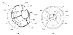
ここに,図1は本発明の実施の形態に係る電気掃除機Xの外観図,図2及び図3は本発明の実施の形態に係るサイクロン集塵装置Yの内部構造を説明するための断面図,図4は本発明の実施の形態に係るサイクロン集塵装置Yに設けられた塵埃回転部123を説明するための図,図5は本発明の実施の形態に係るサイクロン集塵装置Yに設けられた上部フィルタユニット13を説明するための図,図6はフィルタ除塵部材132における二つの接触部132aの配置例を示す図である。Hereinafter, embodiments of the present invention will be described with reference to the accompanying drawings so that the present invention can be understood. The following embodiment is an example embodying the present invention, and does not limit the technical scope of the present invention.
FIG. 1 is an external view of a vacuum cleaner X according to an embodiment of the present invention, and FIGS. 2 and 3 are cross-sectional views for explaining an internal structure of a cyclone dust collecting apparatus Y according to the embodiment of the present invention. FIG. 4 is a diagram for explaining a
まず,図1を用いて,本発明の実施の形態に係る電気掃除機Xの概略構成について説明する。
図1に示すように,前記電気掃除機Xは,掃除機本体部1,吸込口部2,接続管3,接続ホース4,操作ハンドル5などを備えて概略構成されている。前記掃除機本体部1には,不図示の電動送風機V,サイクロン集塵装置Y,制御装置Zなどが内蔵されている。なお,前記サイクロン集塵装置Yについては後段で詳述する。
前記電動送風機Vは,吸気を行うための送風ファン及び該送風ファンを回転駆動する送風駆動モータを有している。前記制御装置Zは,CPUやRAM,ROMなどの制御機器を有してなり,前記電気掃除機Xを統括的に制御する。具体的に,前記制御装置Zでは,前記CPUが前記ROMに記憶された制御プログラムに従って各種の処理を実行する。
なお,前記操作ハンドル5には,ユーザが前記電気掃除機Xの稼働の有無や運転モードの選択操作などを行うための操作スイッチ(不図示)が設けられている。また,その操作スイッチの近傍には,前記電気掃除機Xの現在の状態を表示するLEDなどの表示部(不図示)も設けられている。First, the schematic configuration of the electric vacuum cleaner X according to the embodiment of the present invention will be described with reference to FIG.
As shown in FIG. 1, the electric vacuum cleaner X is schematically configured to include a vacuum cleaner body portion 1, a
The electric blower V has a blower fan for performing intake air and a blower drive motor that rotationally drives the blower fan. The control device Z includes control devices such as a CPU, a RAM, and a ROM, and controls the electric vacuum cleaner X in an integrated manner. Specifically, in the control device Z, the CPU executes various processes according to a control program stored in the ROM.
The operation handle 5 is provided with an operation switch (not shown) for allowing the user to operate the vacuum cleaner X and to select an operation mode. A display unit (not shown) such as an LED for displaying the current state of the electric vacuum cleaner X is also provided in the vicinity of the operation switch.
前記掃除機本体部1は,該掃除機本体部1の前端に接続された前記接続ホース4と,該接続ホース4に接続された前記接続管3とを介して前記吸込口部2に接続されている。
前記電気掃除機Xでは,前記掃除機本体部1に内蔵された前記電動送風機V(不図示)が作動されることにより,前記吸込口部2からの吸気が行われる。そして,前記吸込口部2から吸気された空気は,前記接続管3及び前記接続ホース4を通じて前記サイクロン集塵装置Yに流入する。前記サイクロン集塵装置Yでは,吸い込まれた空気から塵埃が遠心分離される。なお,前記サイクロン集塵装置Yで塵埃が分離された後の空気は,前記掃除機本体部1の後端に設けられた不図示の排気口から排気される。The cleaner body 1 is connected to the
In the electric vacuum cleaner X, the electric blower V (not shown) built in the vacuum cleaner main body 1 is operated, so that intake from the
以下,図2〜6を参照しつつ,前記サイクロン集塵装置Yについて詳説する。
図2及び図3に示すように,前記サイクロン集塵装置Yは,筐体10,集塵容器11,内筒12,上部フィルタユニット13,塵埃受部14及び除塵駆動機構15などを備えて概略構成されている。
前記サイクロン集塵装置Yでは,前記集塵容器11,前記内筒12,前記上部フィルタユニット13,及び前記塵埃受部14が,中心軸Pを中心に同軸上に配置されている。また,前記サイクロン集塵装置Yは,前記掃除機本体部1に着脱可能に構成されている。Hereinafter, the cyclone dust collector Y will be described in detail with reference to FIGS.
As shown in FIGS. 2 and 3, the cyclone dust collecting apparatus Y includes a
In the cyclone dust collecting apparatus Y, the
前記集塵容器11は,吸い込まれた空気から分離された塵埃を収容するための円筒状の容器である。前記集塵容器11は,前記サイクロン集塵装置Yの筐体10に着脱可能に構成されている。
ユーザは,前記掃除機本体部1から前記サイクロン集塵装置Yを取り出した後,該サイクロン集塵装置Yから前記集塵容器11を取り外して,該集塵容器11内の塵埃を廃棄する。
なお,前記サイクロン集塵装置Yの筐体10と前記集塵容器11との間には,環状のシール部材161が設けられている。このシール部材161により,前記筐体10及び前記集塵容器11の間の空気の漏れが防止される。The
After the user removes the cyclone dust collector Y from the cleaner body 1, the user removes the
An
図2に示すように,前記集塵容器11には,前記接続ホース4(図1参照)が接続される接続部111が設けられている。前記吸込口部2から前記接続管3及び前記接続ホース4を通じて吸い込まれた空気は,前記接続部111から前記集塵容器11内に流入する。
ここで,前記接続部111の前記集塵容器11への空気流入口(不図示)は,前記接続ホース4からの空気が前記集塵容器11内で旋回するように形成されている。具体的に,前記空気流入口(不図示)は,前記集塵容器11側の出口が該集塵容器11の円周の接線方向(略接線方向)に向くように形成されている。このように,前記集塵容器11では,吸い込まれた空気を旋回させることで,該空気に含まれた塵埃が遠心力によって分離(遠心分離)される。そして,前記集塵容器11で遠心分離された塵埃は,該集塵容器11の底部に収容される(図2,3の塵埃D1)。
一方,前記集塵容器11で塵埃が分離された後の空気は,該集塵容器11から排気経路110に沿って前記掃除機本体部1に設けられた不図示の排気口から外部に排気される。ここで,前記集塵容器11から前記排気口(不図示)までの前記排気経路110上には,前記内筒12,前記塵埃受部14,及び前記上部フィルタユニット13が順に配置されている。As shown in FIG. 2, the
Here, the air inlet (not shown) of the connecting
On the other hand, the air after the dust is separated in the
また,前記集塵容器11の底部には,前記内筒12に設けられた後述の底筒123cに嵌合する嵌合部11aが設けられている。前記嵌合部11aは,例えば不図示のネジなどによって前記集塵容器11の底部に固定される。前記嵌合部11a下端の外周部には,前記内筒12の底筒123cとの隙間を埋めるための環状のシール部材11bが設けられている。このシール部材11bにより,前記底筒123c及び前記集塵容器11の間の空気の漏れが防止される。
前記嵌合部11aは,前記内筒12の底筒123cが嵌合されることにより該内筒12の内部を上下に仕切る仕切板112(塵埃堆積部の一例)を有している。これにより,前記内筒12の内部には,前記仕切板112よりも下側の空間に塵埃収容部112aが形成される。前記仕切板112には,前記内筒12の内部の塵埃が堆積される。Further, a
The
前記塵埃収容部112aは,前記仕切板112によって前記内筒12の前記仕切板112よりも上方の空間と仕切られた空間である。但し,前記仕切板112には,その一部に開口113及びスロープ114(図4(b)参照)が設けられている。従って,前記内筒12の前記仕切板112よりも上方の空間と前記塵埃収容部112aとの間は,前記開口113で連通している。
前記スロープ114は,前記集塵容器11における空気の旋回方向と同方向に,徐々に下方に傾斜するように形成された傾斜面である(図4(b)参照)。そして,前記開口113は,前記スロープ114の下方の終端に形成されている。The
The
前記内筒12は,前記集塵容器11内に配置された円筒状の部材である。ここで,前記内筒12は,前記塵埃受部14によって回転可能に支持されている。具体的に,前記内筒12は,該内筒12の上端に設けられた環状の凹部12aが,前記塵埃受部14の下端に設けられた環状の支持部14cに支持されることにより回転可能な状態で吊り下げられている。なお,前記内筒12を回転可能に支持する構成は,これに限られるものではない。例えば,前記内筒12の上下の端部を軸支することが一例として考えられる。
さらに,前記内筒12の上端には,後述の傾斜除塵部材134に設けられた係合部134cに係合する複数の連結部12bが設けられている。前記連結部12bは,前記内筒12の上端の開口縁部に上方に突出して設けられたリブである。前記内筒12は,前記連結部12b及び前記係合部134cの係合によって,前記傾斜除塵部材134に一体回転可能に連結されている。これにより,前記内筒12は,前記傾斜除塵部材134に連動して回転することになる。なお,前記内筒12及び前記傾斜除塵部材134の連結構造はこれに限られない。例えば,前記内筒12及び前記傾斜除塵部材134各々に設けられた嵌合部を嵌合させることにより一体回転可能に連結する構成が考えられる。The
Furthermore, a plurality of connecting
また,前記内筒12の上部には,前記集塵容器11で塵埃が分離された後の空気を,上方の前記上部フィルタユニット13に向けて排気するための内筒排気口121が形成されている。そして,前記内筒排気口121には,該内筒排気口121全体を覆う円筒状を成す内筒フィルタ122が設けられている。前記内筒フィルタ122は,前記内筒排気口121を通過する空気を濾過する。
例えば,前記内筒フィルタ122は,メッシュ状のエアフィルタ等である。なお,前記内筒フィルタ122は,前記内筒排気口121の内側又は外側のいずれに設けられていてもよい。また,前記排気口121及び前記内筒フィルタ122に換えて,前記内筒12にメッシュ状の孔を形成する構成も考えられる。その場合は,そのメッシュ状の孔が前記内筒排気口121及び前記内筒フィルタ122として機能する。In addition, an inner
For example, the
一方,前記内筒12の下部には,前記集塵容器11内の塵埃を回転させるための塵埃回転部123が設けられている。
ここで,図2及び図3に加えて図4を参照しつつ,前記塵埃回転部123について説明する。ここに,図4(a)は,前記塵埃回転部123の斜視図,図4(b)は図2におけるA−A矢視断面図である。
図2〜4に示されているように,前記塵埃回転部123には,回転羽根123a,塵埃圧縮部123b,底筒123c及び除塵ブレード123dが設けられている。
前記除塵ブレード123dは,前記内筒12が前記集塵容器11の嵌合部11aに嵌合されたとき,該嵌合部11aの仕切板112の上面に当接するように該内筒12の内部に設けられている。なお,前記除塵ブレード123dは,第一の除塵部材の一例に過ぎず,他にブラシなどを用いてもよい。On the other hand, a
Here, the
As shown in FIGS. 2 to 4, the
When the
前記底筒123cは,前記集塵容器11の底部に設けられた前記嵌合部11aに嵌合される中空円筒である。前述したように,前記底筒123c及び前記嵌合部11aの間には前記シール部材11b(図2,3参照)が介在する。
また,前記底筒123cには,該底筒123cの外周面から突出する4つの回転羽根123aが設けられている。前記回転羽根123a各々は,後述するように前記内筒12が回転されるとき,前記集塵容器11内に集積された塵埃に接触する。これにより,前記集塵容器11内の塵埃は該集塵容器11内で回転移動することになる。
このことは,例えば前記サイクロン集塵装置Yの集塵容器11に集積された塵埃量を光学式センサなど(不図示)で検知する際に利用することが考えられる。即ち,前記内筒12を回転させながら前記光学式センサによる検知を行うことで,前記集塵容器11内の塵埃の集積量を一部だけではなく該集塵容器11の全周に亘って総合的に判断することができる。
さらに,前記内筒12が回転されるとき,前記回転羽根123aは前記集塵容器11との間で塵埃を圧縮しながら回転することになる。また,前記サイクロン集塵装置Yでは,前記内筒12が回転されるとき,前記塵埃圧縮部123bも前記集塵容器11との間で塵埃を圧縮する。これにより,前記集塵容器11に集積された塵埃は凝縮される。このような構成によれば,前記集塵容器11の塵埃の集積可能量を増加させることができる。従って,例えば前記集塵容器11の小型化を実現することが可能である。The
The
This can be used, for example, when detecting the amount of dust accumulated in the
Further, when the
一方,前記内筒12の内筒フィルタ122で濾過された後の空気は,該内筒12内を通じて上方の前記上部フィルタユニット13に導かれる。
ここで,前記集塵容器11から前記内筒12の内部に流れた空気に,細かい塵埃などが含まれている場合,その塵埃は,前記内筒12の上方の前記上部フィルタユニット13に付着し,或いは前記内筒12の内部で下方に落下して前記仕切板112上に堆積することになる。
ここで,図2及び図3に加えて図5を参照しつつ,前記上部フィルタユニット13について説明する。ここに,図5(a)は,前記上部フィルタユニット13を上方から見た斜視図,図5(b)は,前記上部フィルタユニット13を下方から見た斜視図である。
前記上部フィルタユニット13は,HEPAフィルタ(High Efficiency Particulate Air Filter)131,フィルタ除塵部材132(第二の除塵部材の一例)及び傾斜除塵部材134などを有している。On the other hand, the air after being filtered by the
Here, when fine dust or the like is contained in the air flowing from the
Here, the
The
前記HEPAフィルタ131は,前記内筒12の上方に配置されており,該内筒12から排気されて前記排気経路110上を流れる空気を更に濾過するエアフィルタの一種である。ここに,前記HEPAフィルタ131が上方濾過部材の一例である。前記HEPAフィルタ131は,前記中心軸P周りに環状に配置固定された複数枚のフィルタの集合で構成されている。なお,複数枚のフィルタ各々は,例えば図5(b)に示すような骨組みに固定される。また,前記HEPAフィルタ131に含まれた複数枚のフィルタは,略水平方向に凹凸を繰り返すプリーツ状に配置されている。これにより,前記HEPAフィルタ131におけるフィルタ面積が十分に確保されている。なお,前記HEPAフィルタ131の下端と前記筐体10との間には,環状のシール部材162が設けられている。これにより,前記HEPAフィルタ131と前記筐体10との間の空気の漏れが防止される。
また,図2及び図3に示すように,前記HEPAフィルタ131の中央には,後述のフィルタ除塵部材132に設けられた連結部133が嵌挿される中空部131aが形成されている。また,前記中空部131aには,前記連結部133を回転可能に支持する支持部131bが設けられている。The
As shown in FIGS. 2 and 3, a
前述したように,前記サイクロン集塵装置Yでは,前記内筒フィルタ122及び前記HEPAフィルタ131の二段階で空気を濾過することにより塵埃の捕集力が高められている。
但し,前記HEPAフィルタ131に塵埃が堆積して目詰まりが生じると,空気の通過抵抗が大きくなる。そのため,前記電動送風機V(不図示)の負荷が大きくなり吸塵力が低下するおそれがある。そこで,前記上部フィルタユニット13には,前記HEPAフィルタ131に付着した塵埃を除去する前記フィルタ除塵部材132が設けられている。As described above, in the cyclone dust collector Y, the dust collecting power is enhanced by filtering the air in two stages of the
However, if dust accumulates on the
前記フィルタ除塵部材132は,前記HEPAフィルタ131の支持部131aに回転可能に支持される連結部133を有している。これにより,前記フィルタ除塵部材132は,前記HEPAフィルタ131に回転可能に支持される。
前記連結部133には,該連結部133に設けられたネジ穴133aに前記傾斜除塵部材134がネジ133bで螺着される。これにより,前記フィルタ除塵部材132及び前記傾斜除塵部材134が一体回転可能に連結される。なお,前記傾斜除塵部材134及び前記HEPAフィルタ131の間には,隙間を埋める環状のシール部材163が設けられている。これにより,前記傾斜除塵部材134及び前記HEPAフィルタ131の間の空気の漏れが防止される。The filter
The inclined
前記フィルタ除塵部材132は,図2及び図5(a)に示すように,前記HEPAフィルタ131の上端部に接触するように該HEPAフィルタ131に沿って所定間隔で配置された二つの接触部132aを有している。前記接触部132aは板バネ状の弾性部材である。なお,前記接触部132aは,板バネ状の弾性部材に限られるものではない。また,前記接触部132aは,一つであっても或いは更に複数であってもよい。
そして,前記フィルタ除塵部材132には,その外周部にギア132bが形成されている。このギア132bは,図2及び図3に示すように,前記サイクロン集塵装置Yに設けられた除塵駆動機構15に設けられたギア15aに噛合される。As shown in FIGS. 2 and 5A, the filter
The filter
ここに,前記除塵駆動機構15は,前記掃除機本体部1側に設けられた不図示の駆動モータ(以下,「除塵駆動モータ」という)に連結される減速器及び該減速器に連結されたギア15aを有している。前記除塵駆動機構15では,前記除塵駆動モータの回転力が前記減速器を介して前記ギア15aに伝達される。そして,前記除塵駆動機構15のギア15aの回転力は,前記ギア132bに伝達される。これにより,前記フィルタ除塵部材132が回転される。ここに,前記除塵駆動モータ及び前記除塵駆動機構15が除塵部材回転駆動手段の一例である。
なお,本実施の形態では,前記除塵駆動モータによって前記フィルタ除塵部材132が回転される場合を例に挙げて説明するが,前記除塵駆動モータに換えて,前記フィルタ除塵部材132を手動で回転させることのできる機構を設けることも他の実施例として考えられる。
前記フィルタ除塵部材132が回転されると,該フィルタ除塵部材132に設けられた二つの前記接触部132a各々は,プリーツ状に形成された前記HEPAフィルタ131に断続的に衝突して振動を与える。従って,前記HEPAフィルタ131に付着した塵埃は,前記フィルタ除塵部材132から与えられる振動によって叩き落とされる。なお,前記除塵駆動モータ(不図示)が作動されるタイミングは,例えば前記電気掃除機Xにおける集塵動作の開始前や終了後であることが望ましい。これにより,前記電動送風機Vによる吸気によって前記HEPAフィルタ131に下流側への気流がない状態で,前記HEPAフィルタ131の除塵を効果的に行うことができる。Here, the dust
In the present embodiment, the case where the filter
When the filter
ここで,図6を用いて,前記フィルタ除塵部材132における二つの接触部132aの配置例について説明する。ここに,図6は,前記上部フィルタユニット13を上方から見た模式図である。
図6(a)に示す例では,前記フィルタ除塵部材132の二つの接触部132aが,前記HEPAフィルタ131に同じタイミングで接触するように配置されている。このような構成では,二つの接触部132aが同時に前記HEPAフィルタ131に衝突する。
一方,図6(b)に示す例では,前記フィルタ除塵部材132の二つの接触部132aが,前記HEPAフィルタ131に異なるタイミングで接触するように配置されている。このような構成では,図6(a)に示したように同時に接触する場合に比べて,前記HEPAフィルタ131に与えられる振動の数を倍増させることができる。これにより,前記HEPAフィルタ131の高い除塵効果を得ることができる。また,前記フィルタ除塵部材132を回転させるために必要な瞬間最大トルクも小さくすることができ,前記除塵駆動モータ(不図示)に小型モータを採用することができる。
その他,より多くの接触部132aを有する場合には,同じタイミングで接触する接触部132aと,異なるタイミングで接触する接触部132aとが混在するように構成してもよい。Here, the example of arrangement | positioning of the two
In the example shown in FIG. 6A, the two
On the other hand, in the example shown in FIG. 6B, the two
In addition, when it has
ところで,前記フィルタ除塵部材132によって前記HEPAフィルタ131から除去された塵埃(図2,3の塵埃D2)は,該HEPAフィルタ131の下方に設けられた前記塵埃受部14に落下して受けられる(図2,3の塵埃D3)。
前記塵埃受部14は,前記フィルタ除塵部材132及び前記内筒12の間に配置されており,その中心に設けられた開口14aから上方に向けて拡開する傾斜面14bを有するすり鉢状の部材である。前記開口14aは,その下方に配置された前記内筒12の内部に接続されている。
また,前述したように,前記塵埃受部14は,前記内筒12を回転可能に支持している。具体的に,前記塵埃受部14の開口14a縁部の下端には,前記内筒12の上端に設けられた環状の凹部12aに嵌合される環状の支持部14cが設けられている。これにより,前記内筒12は,前記塵埃受部14によって回転可能な状態で吊り下げられている。By the way, the dust (dust D2 in FIGS. 2 and 3) removed from the
The
As described above, the
前記HEPAフィルタ131から前記塵埃受部14に落下した塵埃(図2,3の塵埃D3)は,前記傾斜面14bから前記開口14aを通じて前記内筒12内に滑落する。しかし,前記傾斜面14bに付着した塵埃が滑落せずに残存していると,前記電動送風機V(不図示)が作動されたときに,その吸気によって前記斜面部14bの塵埃が再び前記HEPAフィルタ131に付着することになる。
そこで,前記サイクロン集塵装置Yには,前記塵埃受部14の傾斜面14bに付着した塵埃をより確実に前記内筒12内に導くべく,前記傾斜除塵部材134が設けられている。Dust (dust D3 in FIGS. 2 and 3) dropped from the
In view of this, the cyclone dust collector Y is provided with the inclined
ここで,図2,図3及び図5(b)を参照して,前記傾斜除塵部材134について説明する。
前記傾斜除塵部材134には,先端にブラシ134aを有する二つの除塵ブレード134bが設けられている。前記ブラシ134a各々は,前記塵埃受部14の傾斜面14bに当接している(図3参照)。
また,前述したように,前記傾斜除塵部材134は,前記フィルタ除塵部材132に一体回転可能に連結されている。そのため,前記フィルタ除塵部材132が回転されると,それに連動して前記傾斜除塵部材134も同時に回転する。
前記傾斜除塵部材134が回転されると,前記除塵ブレード134bのブラシ134a各々が,前記傾斜面14bに接触しながら回転することになる。これにより,前記傾斜面14bに付着した塵埃を,前記ブラシ134a各々によって除去し,前記内筒12内に導くことができる。Here, the inclined
The inclined
Further, as described above, the inclined
When the inclined
ところが,前記傾斜面14bから前記内筒12内に落下した塵埃は,前記内筒フィルタ122の内面に付着するおそれがある(図2,3の塵埃D4)。
前記内筒フィルタ121の内面に塵埃が付着したまま,前記電動送風機V(不図示)による吸気が行われると,その塵埃が,前記HEPAフィルタ131に再度付着することになる。そのため,前記サイクロン集塵装置Yでは,さらに,前記内筒フィルタ121に付着した塵埃の除去を図る構成が採られている。
具体的には,図2,3及び図5(b)に示すように,前記除塵ブレード134bの下端に,前記内筒12に設けられた前記連結部12bに係合する係合部134cが設けられている。そして,前述したように,前記傾斜除塵部材134及び前記内筒12は,前記連結部12b及び前記係合部134cの係合によって一体回転可能に連結される。ここに,前記連結部12b及び前記係合部134cが内筒回転駆動手段の一例である。
これにより,前記除塵駆動モータ(不図示)によって前記フィルタ除塵部材132が回転され,前記傾斜除塵部材134が回転すると,前記内筒12も同時に回転する。なお,前記フィルタ除塵部材132ではなく前記HEPAフィルタ131が回転可能に設けられる構成では,前記内筒12を前記HEPAフィルタ131に一体回転可能に連結することが考えられる。However, dust that has fallen into the
If suction is performed by the electric blower V (not shown) while dust is attached to the inner surface of the
Specifically, as shown in FIGS. 2, 3 and 5B, an engaging
As a result, when the filter
このように構成された前記サイクロン集塵装置Yでは,前記フィルタ除塵部材132の接触部132a各々が前記HEPAフィルタ131に断続的に衝突するときに生じる振動が,前記傾斜除塵部材134を介して前記内筒12にも伝達される。従って,その断続的な振動によって,前記内筒12の内筒フィルタ122に付着した塵埃(図2,3の塵埃D4)を剥離させて前記仕切板112上に落下させることができる(図2,3の塵埃D5)。また,これと同時に,前記内筒フィルタ122の外面に付着した塵埃の除去も期待される。 In the cyclone dust collector Y configured as described above, vibrations generated when the
そして,前記HEPAフィルタ131や前記内筒フィルタ122などから落下した塵埃は,前記内筒12の内部下方にある前記仕切板112の上面に堆積する。なお,前記仕切板112の上面には,前記集塵容器11から前記内筒12の内部に流入した空気に含まれた細かい塵埃なども堆積する。
ここで,前記仕切板112の上面に塵埃が残留した状態で前記電動送風機V(不図示)が作動されると,その塵埃は上方に舞い上がって前記HEPAフィルタ131や前記内筒フィルタ122などに再び付着するおそれがある。
しかし,前記サイクロン集塵装置Yでは,前記仕切板112に,前記開口113及び前記スロープ114が設けられているため,前記内筒12内に発生する空気の旋回流によって,前記仕切板112の上面の塵埃(図2,3の塵埃D5)は,前記スロープ114から前記開口113を通じて滑落し,該仕切板112の下部空間112b内に収容される(図2,3の塵埃D6)。これにより,前記内筒12の内部下方に落下した塵埃が再度,上方へ舞い上がることが防止される。Dust falling from the
Here, when the electric blower V (not shown) is operated in a state where dust remains on the upper surface of the
However, in the cyclone dust collector Y, since the
さらに,前記サイクロン集塵装置Yでは,前述したように前記内筒12の内部に,前記仕切板112の上面に当接する前記除塵ブレード123dが設けられている。そのため,前記内筒12が回転されると,前記除塵ブレード123dが前記仕切板112の上面を摺動することになる。
これにより,前記仕切板112の上面に堆積した塵埃は,前記除塵ブレード123dによって確実に前記開口113に導かれ,前記下部空間112b内に落下して収容される。なお,前記内筒12が回転されるタイミング,即ち,前記除塵駆動モータ(不図示)が作動されるタイミングは,前述したように,例えば前記電気掃除機Xにおける集塵動作の開始前や終了後である。また,
なお,ここでは,前記除塵駆動モータ(不図示)を前記内筒12の回転させるための駆動手段として用いる場合を例に挙げているが,これに限られず,前記内筒12を回転し得る構成であればよい。Further, in the cyclone dust collector Y, the
As a result, the dust accumulated on the upper surface of the
In addition, although the case where the said dust removal drive motor (not shown) is used as a drive means for rotating the said
以上,説明したように,前記サイクロン集塵装置Yでは,前記内筒12が回転されることにより,該内筒12の内部下方に落下して前記仕切板112に堆積した塵埃が,前記除塵ブレード123dによって前記下部空間112b内に導かれる。
これにより,前記サイクロン集塵装置Yでは,前記HEPAフィルタ131から除去された塵埃が,再び上方に舞い上がって前記HEPAフィルタ131などに付着することをより確実に防止することができる。また,前記スロープ114が,前記内筒12内で生じる空気の旋回方向と同方向に形成されているため,前記塵埃収容部112a内の塵埃が,前記スロープ114を通じて上部に吹き上がることはない。As described above, in the cyclone dust collector Y, when the
Thereby, in the cyclone dust collector Y, the dust removed from the
ところで,前記実施の形態では,前記仕切板112によって前記内筒12の内部を上下に仕切り,その下側の領域である塵埃収容部112aを塵埃の収容に用いる場合を説明した。しかし,本発明は,これに限られるものではない。
ここに,図7は,本発明の実施例に係るサイクロン集塵装置Y1に設けられた集塵容器11´を説明するための要部断面模式図である。なお,前記実施の形態で説明したサイクロン集塵装置Yと同様の構成要素には同じ符号を付してその説明を省略する。
図7に示すように,前記サイクロン集塵装置Y1の集塵容器11´には,その底部に,前記内筒12の内部の塵埃が堆積される仕切板112´(塵埃堆積部の一例)と,前記仕切板112´によって前記内筒12の前記仕切板112´よりも上方の空間と仕切られた塵埃収容部112a´とが設けられている。即ち,前記集塵容器11´では,該集塵容器11´の底面が二重に形成されており,その間の空間を前記内筒12内の塵埃の収容部として用いるものである。By the way, in the said embodiment, the inside of the said
FIG. 7 is a schematic cross-sectional view of an essential part for explaining the
As shown in FIG. 7, the
そして,前記仕切板112´の一部には,前記仕切板112と同様に前記内筒12の前記仕切板112´よりも上方の空間,即ち前記内筒12の内部と前記塵埃収容部112a´とを連通する開口113´が形成されている。もちろん,前記集塵容器11と同様に前記仕切板112´にスロープ114が設けられていてもよい。
一方,前記内筒12の内部には,該内筒12及び前記集塵容器11´が連結されたときに,前記仕切板112´の上面に当接する除塵ブレード123d´(第一の除塵部材の一例)が設けられている。
このように構成された前記サイクロン集塵装置Y1では,前記内筒12の内部下方に落下して前記仕切板112´の上面に堆積した塵埃は,前記内筒12が回転されることにより,前記除塵ブレード123d´によって前記開口113´に導かれ,前記塵埃収容部112a´内に収容される。これにより,前記HEPAフィルタ131から除去された塵埃が,再び上方に舞い上がって前記HEPAフィルタ131などに付着することをより確実に防止することができる。なお,前記塵埃収容部112a´の塵埃を廃棄するための廃棄口を設けておく必要があることは言うまでもない。Further, a part of the
On the other hand, when the
In the cyclone dust collector Y1 configured in this way, the dust that falls down inside the
本発明は,吸い込まれた空気を集塵容器で旋回させることにより塵埃を遠心分離するサイクロン集塵装置を備えた所謂サイクロン式の電気掃除機に利用することができる。 INDUSTRIAL APPLICABILITY The present invention can be used for a so-called cyclonic type electric vacuum cleaner provided with a cyclone dust collecting device that centrifugally separates dust by swirling sucked air in a dust collecting container.
1…掃除機本体部
2…吸込口部
3…接続管
4…接続ホース
5…操作ハンドル
X…電気掃除機
Y…サイクロン集塵装置
10…筐体
11,11´…集塵容器
11a…嵌合部
11b…シール部材
112,112´…仕切板
112a,112a´…塵埃収容部
113,113´…開口
114…スロープ
12…内筒
12a…凹部
12b…連結部
121…内筒排気口
122…内筒フィルタ
123…塵埃回転部
123a…回転羽根
123b…塵埃圧縮部
123c…底筒
123d…除塵ブレード
13…上部フィルタユニット
131…HEPAフィルタ
131a…中空部
131b…支持部
132…フィルタ除塵部材
132a…接触部
132b…ギア
133…連結部
134…傾斜除塵部材
134a…ブラシ
134b…除塵ブレード
134c…係合部
14…塵埃受部
14a…開口
14b…傾斜面
14c…支持部
15…除塵駆動機構
161〜163…シール部材DESCRIPTION OF SYMBOLS 1 ... Vacuum cleaner
Claims (4)
Translated fromJapanese前記内筒を回転させる内筒回転駆動手段と,前記集塵容器の底部に設けられ,前記内筒の内部の塵埃が堆積される塵埃堆積部と,前記塵埃堆積部によって前記内筒の前記塵埃堆積部よりも上方の空間と仕切られた塵埃収容部と,を備えてなり,
前記塵埃堆積部の一部に,前記内筒の前記塵埃堆積部よりも上方の空間と前記塵埃収容部とを連通する開口が形成されてなり,
前記内筒に,前記塵埃堆積部の上面に当接する第一の除塵部材が設けられてなることを特徴とするサイクロン集塵装置。A dust collecting container that accommodates the dust centrifuged from the air by swirling the sucked air, and disposed in the dust collecting container, and the air after the dust is separated in the dust collecting container A cyclone dust collector comprising: a cylindrical inner cylinder having an exhaust port for discharging toward the
Inner cylinder rotation driving means for rotating the inner cylinder, a dust accumulation part provided at the bottom of the dust collecting container, in which dust inside the inner cylinder is accumulated, and the dust in the inner cylinder by the dust accumulation part A space above the accumulation portion and a dust storage portion partitioned;
An opening that communicates the space above the dust accumulation portion of the inner cylinder and the dust container is formed in a part of the dust accumulation portion,
A cyclone dust collector, wherein the inner cylinder is provided with a first dust removing member that contacts the upper surface of the dust accumulation portion.
前記塵埃収容部が,前記内筒の内部に形成された前記塵埃堆積部よりも下側の空間である請求項1に記載のサイクロン集塵装置。The dust accumulation part is configured to partition the inside of the inner cylinder vertically by fitting the inner cylinder,
The cyclone dust collecting apparatus according to claim 1, wherein the dust container is a space below the dust accumulation part formed in the inner cylinder.
前記内筒回転駆動手段が,前記内筒を前記第二の除塵部材に一体回転可能に連結するものである請求項1又は2のいずれかに記載のサイクロン集塵装置。An upper filtering member disposed above the inner cylinder and further filtering air exhausted from the inner cylinder; a second dust removing member that intermittently vibrates the upper filtering member by rotating; A dust removing member rotating drive means for rotating the second dust removing member,
The cyclone dust collecting device according to claim 1 or 2, wherein the inner cylinder rotation driving means connects the inner cylinder to the second dust removing member so as to be integrally rotatable.
The vacuum cleaner provided with the cyclone dust collector in any one of Claims 1-3.
Priority Applications (1)
| Application Number | Priority Date | Filing Date | Title |
|---|---|---|---|
| JP2007223873AJP2009055980A (en) | 2007-08-30 | 2007-08-30 | Cyclone dust collector, vacuum cleaner |
Applications Claiming Priority (1)
| Application Number | Priority Date | Filing Date | Title |
|---|---|---|---|
| JP2007223873AJP2009055980A (en) | 2007-08-30 | 2007-08-30 | Cyclone dust collector, vacuum cleaner |
Publications (1)
| Publication Number | Publication Date |
|---|---|
| JP2009055980Atrue JP2009055980A (en) | 2009-03-19 |
Family
ID=40552297
Family Applications (1)
| Application Number | Title | Priority Date | Filing Date |
|---|---|---|---|
| JP2007223873APendingJP2009055980A (en) | 2007-08-30 | 2007-08-30 | Cyclone dust collector, vacuum cleaner |
Country Status (1)
| Country | Link |
|---|---|
| JP (1) | JP2009055980A (en) |
Cited By (8)
| Publication number | Priority date | Publication date | Assignee | Title |
|---|---|---|---|---|
| JP2012029732A (en)* | 2010-07-28 | 2012-02-16 | Toshiba Corp | Vacuum cleaner |
| JP2014000343A (en)* | 2012-06-21 | 2014-01-09 | Panasonic Corp | Vacuum cleaner |
| WO2014027498A1 (en) | 2012-08-15 | 2014-02-20 | 三菱電機株式会社 | Cyclone separation device and electric vacuum cleaner with same |
| JP2014033842A (en)* | 2012-08-09 | 2014-02-24 | Panasonic Corp | Vacuum cleaner |
| US10143345B2 (en) | 2016-01-22 | 2018-12-04 | Dyson Technology Limited | Vacuum cleaning apparatus |
| US10299648B2 (en) | 2016-01-22 | 2019-05-28 | Dyson Technology Limited | Vacuum cleaner |
| US10390670B2 (en) | 2016-01-22 | 2019-08-27 | Dyson Technology Limited | Separating apparatus and vacuum cleaner |
| CN110338704A (en)* | 2019-07-31 | 2019-10-18 | 苏州诚河清洁设备有限公司 | Cyclone separator |
- 2007
- 2007-08-30JPJP2007223873Apatent/JP2009055980A/enactivePending
Cited By (9)
| Publication number | Priority date | Publication date | Assignee | Title |
|---|---|---|---|---|
| JP2012029732A (en)* | 2010-07-28 | 2012-02-16 | Toshiba Corp | Vacuum cleaner |
| JP2014000343A (en)* | 2012-06-21 | 2014-01-09 | Panasonic Corp | Vacuum cleaner |
| JP2014033842A (en)* | 2012-08-09 | 2014-02-24 | Panasonic Corp | Vacuum cleaner |
| WO2014027498A1 (en) | 2012-08-15 | 2014-02-20 | 三菱電機株式会社 | Cyclone separation device and electric vacuum cleaner with same |
| US9661969B2 (en) | 2012-08-15 | 2017-05-30 | Mitsubishi Electric Corporation | Cyclone separation device and electric vacuum cleaner with same |
| US10143345B2 (en) | 2016-01-22 | 2018-12-04 | Dyson Technology Limited | Vacuum cleaning apparatus |
| US10299648B2 (en) | 2016-01-22 | 2019-05-28 | Dyson Technology Limited | Vacuum cleaner |
| US10390670B2 (en) | 2016-01-22 | 2019-08-27 | Dyson Technology Limited | Separating apparatus and vacuum cleaner |
| CN110338704A (en)* | 2019-07-31 | 2019-10-18 | 苏州诚河清洁设备有限公司 | Cyclone separator |
Similar Documents
| Publication | Publication Date | Title |
|---|---|---|
| JP4798637B2 (en) | Dust collector and vacuum cleaner | |
| CN102438497B (en) | Vacuum cleaner provided with dust-removing device | |
| JP2009055980A (en) | Cyclone dust collector, vacuum cleaner | |
| RU2276962C1 (en) | Filtering unit for vacuum cleaner | |
| JP2009061307A (en) | Electric vacuum cleaner | |
| JP2010035771A (en) | Cyclone separator | |
| JP4904226B2 (en) | Cyclone dust collector, vacuum cleaner | |
| CN101712015A (en) | Cyclone separation device | |
| JP2008253376A (en) | Centrifugal dust collector and vacuum cleaner provided with the same | |
| JP2016026686A (en) | Cyclone dust collector, vacuum cleaner | |
| JP5031807B2 (en) | Cyclone separator | |
| JP2007021083A (en) | Electric vacuum cleaner | |
| JP4904225B2 (en) | Cyclone dust collector, vacuum cleaner | |
| JP4767928B2 (en) | Vacuum cleaner | |
| JP2010082236A (en) | Vacuum cleaner | |
| JP2010046337A (en) | Cyclone separation apparatus | |
| JP4812901B2 (en) | Cyclone dust collector, vacuum cleaner | |
| JP2009254784A (en) | Cyclone separator | |
| JP4907471B2 (en) | Vacuum cleaner | |
| JP4939667B2 (en) | Cyclone dust collector, vacuum cleaner | |
| JP5108972B2 (en) | Cyclone dust collector, vacuum cleaner | |
| JP5827390B2 (en) | Cyclone dust collector, vacuum cleaner | |
| JP6491779B2 (en) | Dust collector and vacuum cleaner | |
| JP4939664B2 (en) | Cyclone dust collector, vacuum cleaner | |
| JP2008207085A (en) | Centrifugal force dust collector and electric vacuum cleaner using the same |