JP2009053184A - Rotary unit for noncontact sensor and rotary device for noncontact sensor - Google Patents
Rotary unit for noncontact sensor and rotary device for noncontact sensorDownload PDFInfo
- Publication number
- JP2009053184A JP2009053184AJP2008184984AJP2008184984AJP2009053184AJP 2009053184 AJP2009053184 AJP 2009053184AJP 2008184984 AJP2008184984 AJP 2008184984AJP 2008184984 AJP2008184984 AJP 2008184984AJP 2009053184 AJP2009053184 AJP 2009053184A
- Authority
- JP
- Japan
- Prior art keywords
- contact sensor
- rotation
- degrees
- unit
- rotating
- Prior art date
- Legal status (The legal status is an assumption and is not a legal conclusion. Google has not performed a legal analysis and makes no representation as to the accuracy of the status listed.)
- Withdrawn
Links
- 238000005259measurementMethods0.000description9
- 230000001276controlling effectEffects0.000description4
- 230000001105regulatory effectEffects0.000description3
- 238000006073displacement reactionMethods0.000description2
- 230000000694effectsEffects0.000description2
- 238000010586diagramMethods0.000description1
- 238000010792warmingMethods0.000description1
Images


Classifications
- G—PHYSICS
- G01—MEASURING; TESTING
- G01B—MEASURING LENGTH, THICKNESS OR SIMILAR LINEAR DIMENSIONS; MEASURING ANGLES; MEASURING AREAS; MEASURING IRREGULARITIES OF SURFACES OR CONTOURS
- G01B11/00—Measuring arrangements characterised by the use of optical techniques
- G01B11/002—Measuring arrangements characterised by the use of optical techniques for measuring two or more coordinates
- G01B11/005—Measuring arrangements characterised by the use of optical techniques for measuring two or more coordinates coordinate measuring machines
- G01B11/007—Measuring arrangements characterised by the use of optical techniques for measuring two or more coordinates coordinate measuring machines feeler heads therefor
Landscapes
- Physics & Mathematics (AREA)
- General Physics & Mathematics (AREA)
- Length Measuring Devices With Unspecified Measuring Means (AREA)
Abstract
Description
Translated fromJapanese本発明は、一方向に走査可能な非接触センサを利用した3次元測定器等に用いる非接触センサ用回転ユニット及び非接触センサ用回転装置に関する。 The present invention relates to a non-contact sensor rotating unit and a non-contact sensor rotating device used in a three-dimensional measuring instrument using a non-contact sensor that can scan in one direction.
図5に示すように、3次元測定器100は、一方向に走査可能な非接触センサ101と、この非接触センサ101を移動可能に支持するための支持手段102を有している。支持手段102は、3軸構成の支持部材102a、102b、102cと、支持部材102cの先端部に設けられている回転2軸ジョイント102dとから構成されている。 As shown in FIG. 5, the three-dimensional
図6に示すように、非接触センサ101は、回転2軸ジョイント102dの先端部にジョイント部101aを介して固定されている。支持部材102a、102b、102cはそれぞれXYZの3軸に沿って移動可能に構成されており、また、回転2軸ジョイント102dはA軸とB軸の2軸の回転軸を有する(図6及び図7参照)。そして、支持部材102a、102b、102cと回転2軸ジョイント102dとが協働することにより、被測定物に対し非接触センサ101の位置を自由に支持することができる。 As shown in FIG. 6, the
非接触センサ101は、出射したレーザ光を一方向に走査させ、レーザ光の戻り光の受光位置の変位を検出し、被測定物の表面形状を取得するセンサである。即ち、一方向にレーザ光を走査することにより完了する1回の走査範囲は直線状となる。そして、この直線状のレーザ光の走査範囲を少しずつ平行にずらすように非接触センサ101を徐々に移動させ、被測定物の表面形状の3次元マップを取得してゆく。 The
非接触センサ101は、図6に示すように、回転2軸ジョイント102dを駆動し、B軸を中心として回転させることが可能である。回転2軸ジョイント102dの回転前の状態では、レーザ光の走査範囲はR1となっている。そして、回転2軸ジョイント102dを、そのB軸を中心として回転させると、非接触センサ101が回転してレーザ光の走査範囲はR2になる。 As shown in FIG. 6, the
しかし、図7に示すように、回転2軸ジョイント102dを駆動し、A軸を中心として90度回転させた状態では、レーザ光の走査範囲R3の方向を走査範囲R4の方向へ変更することは不可能である。回転2軸ジョイント102dのB軸を中心に回転しても、非接触センサ101は回転2軸ジョイント102dの周囲において円弧を描くように回転するだけだからである。 However, as shown in FIG. 7, in the state where the rotary
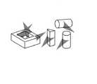
このように非接触センサ101の走査範囲の方向を適宜変更することができない場合、正確な3次元測定を実行できない場合がある。例えば、被測定物の測定面が鏡面である場合には、図8(A)に示すように非接触センサ101が配置されている場合には、戻り光が反射してしまうため正確な測定ができない。この場合、図8(B)に示すように非接触センサ101を90度回転させて走査範囲の方向を変更する必要がある。従来の回転2軸ジョイント102dに装着した状態の非接触センサ101では、このような走査範囲の方向を変更は不可能である。 Thus, when the direction of the scanning range of the
また、図9に示すように、非接触センサ101による走査は、原則として被測定物の断面方向に対して走査することが望ましい。この場合においても、非接触センサ101の走査範囲の方向を変更する必要がある。 In addition, as shown in FIG. 9, it is desirable that the scanning by the
本発明は、非接触センサの走査範囲の方向を容易に変更することができる非接触センサ用回転ユニット及び非接触センサ用回転装置を提供することを目的とする。 An object of the present invention is to provide a non-contact sensor rotating unit and a non-contact sensor rotating device that can easily change the direction of the scanning range of the non-contact sensor.
本発明に係る非接触センサ用回転ユニットは、一方向に走査可能な非接触センサと前記非接触センサを支持する支持手段との間に配設され、前記非接触センサの前記走査方向に対して90度回転可能となっていることを特徴とする。 The rotation unit for a non-contact sensor according to the present invention is disposed between a non-contact sensor capable of scanning in one direction and a support means for supporting the non-contact sensor, and the rotation unit with respect to the scanning direction of the non-contact sensor. It is characterized by being able to rotate 90 degrees.
さらに、本発明に係る非接触センサ用回転ユニットは、前記非接触センサ用回転ユニットの少なくとも0度と90度の回転状態を維持するための位置決め手段を有していることが好ましい。 Furthermore, the non-contact sensor rotating unit according to the present invention preferably has positioning means for maintaining at least 0 degree and 90 degree rotation states of the non-contact sensor rotating unit.
さらに、本発明に係る非接触センサ用回転ユニットは、前記非接触センサ側の第1部材と、前記支持手段側の第2部材とを有し、前記非接触センサ用回転ユニットの少なくとも0度と90度の回転状態において、前記位置決め手段により前記第1部材は前記第2部材により3点支持されることが好ましい。 Furthermore, the non-contact sensor rotation unit according to the present invention includes a first member on the non-contact sensor side and a second member on the support means side, and at least 0 degrees of the rotation unit for the non-contact sensor. In the 90 degree rotation state, it is preferable that the first member is supported by the positioning member at three points by the second member.
さらに、本発明に係る非接触センサ用回転ユニットは、前記第2部材には、前記第1部材に対して前記第2部材を90度回転させるためのレバーが突出して設けられており、前記ロッドは前記非接触センサと別置されている回転補助治具と係合可能となっていることが好ましい。 Further, in the non-contact sensor rotating unit according to the present invention, the second member is provided with a lever protruding to rotate the second member by 90 degrees with respect to the first member, and the rod Is preferably engageable with a rotation assisting jig that is separately provided from the non-contact sensor.
さらに、本発明に係る非接触センサ用回転ユニットは、前記非接触センサ用回転ユニットを90度回転させるための駆動手段を有していることが好ましい。 Furthermore, it is preferable that the non-contact sensor rotation unit according to the present invention includes a driving unit for rotating the non-contact sensor rotation unit by 90 degrees.
本発明に係る非接触センサ用回転装置は、一方向に走査可能な非接触センサと前記非接触センサを支持する支持手段との間に配設され、前記非接触センサの前記走査方向に対して90度回転可能となっている非接触センサ用回転ユニットと、前記非接触センサ用回転ユニットを90度回転させるための回転駆動装置とを有することを特徴とする。 A rotating device for a non-contact sensor according to the present invention is disposed between a non-contact sensor capable of scanning in one direction and a support means for supporting the non-contact sensor, and the non-contact sensor is rotated with respect to the scanning direction of the non-contact sensor. It has a rotation unit for non-contact sensor that can rotate 90 degrees, and a rotation drive device for rotating the rotation unit for non-contact sensor by 90 degrees.
さらに、本発明に係る非接触センサ用回転装置は、前記回転駆動装置が、前記非接触センサへの給電を行うための給電端子を有していることが好ましい。 Furthermore, in the non-contact sensor rotation device according to the present invention, it is preferable that the rotation driving device has a power supply terminal for supplying power to the non-contact sensor.
請求項1記載の本発明によれば、非接触センサ用回転ユニットが、一方向に走査可能な非接触センサと前記非接触センサを支持する支持手段との間に配設され、前記非接触センサの前記走査方向に対して90度回転可能となっているため、非接触センサの走査範囲の方向を90度変更することができ、被測定物の測定面の状況に応じた正確な測定をおこなうことができる。 According to the first aspect of the present invention, the non-contact sensor rotating unit is disposed between the non-contact sensor capable of scanning in one direction and the support means for supporting the non-contact sensor, and the non-contact sensor. Therefore, the direction of the scanning range of the non-contact sensor can be changed by 90 degrees, and an accurate measurement according to the state of the measurement surface of the object to be measured is performed. be able to.
請求項2記載の本発明によれば、前記非接触センサ用回転ユニットが、前記非接触センサ用回転ユニットの少なくとも0度と90度の回転状態を維持するための位置決め手段を有しているため、非接触センサユニットの0度と90度の回転状態が正確に規制され、非接触センサユニットの回転による測定誤差の発生を防止することができる。 According to the second aspect of the present invention, the non-contact sensor rotation unit has positioning means for maintaining at least 0 degrees and 90 degrees of rotation of the non-contact sensor rotation unit. The rotation state of the non-contact sensor unit at 0 degrees and 90 degrees is accurately regulated, and the generation of measurement errors due to the rotation of the non-contact sensor unit can be prevented.
請求項3記載の本発明によれば、前記非接触センサ用回転ユニットが、前記非接触センサ側の第1部材と、前記支持手段側の第2部材とを有し、前記非接触センサ用回転ユニットの少なくとも0度と90度の回転状態において、前記位置決め手段により前記第1部材は前記第2部材により3点支持されるため、第1部材と第2部材との間のガタつきを防止することができる。 According to the third aspect of the present invention, the non-contact sensor rotation unit includes a first member on the non-contact sensor side and a second member on the support means side, and the rotation for the non-contact sensor. Since the first member is supported at three points by the second member by the positioning means when the unit is rotated at least at 0 degrees and 90 degrees, rattling between the first member and the second member is prevented. be able to.
請求項4記載の本発明によれば、前記非接触センサ用回転ユニットにおいて、当該ユニットの第1部材に対して第2部材を90度回転させるためのレバーが突出して設けられており、ロッドは非接触センサと別置されている回転補助治具と係合可能となっているため、非接触センサ用回転ユニットに回転駆動手段を設ける必要がない。 According to the fourth aspect of the present invention, in the non-contact sensor rotating unit, a lever for rotating the second member by 90 degrees with respect to the first member of the unit is provided so as to protrude, and the rod is Since it is possible to engage with a rotation assisting jig placed separately from the non-contact sensor, it is not necessary to provide a rotation driving means in the non-contact sensor rotation unit.
請求項5記載の本発明によれば、前記非接触センサ用回転ユニットが、前記非接触センサ用回転ユニットを90度回転させるための駆動手段を有しているため、例えば、非接触センサの支持手段の位置制御を行うプログラムに、当該非接触用回転ユニットの回転状態をプログラミングすることにより、完全に自動化された3次元測定器を実現することができる。 According to the fifth aspect of the present invention, the non-contact sensor rotation unit has a driving means for rotating the non-contact sensor rotation unit by 90 degrees. By programming the rotational state of the non-contact rotary unit in the program for controlling the position of the means, a fully automated three-dimensional measuring instrument can be realized.
請求項6記載の本発明によれば、非接触センサ用回転ユニットと、非接触センサ用回転ユニットを90度回転させるための回転駆動装置とを有しているために、回転駆動装置によって非接触センサ用回転ユニットを90度回転することができる。 According to the sixth aspect of the present invention, since the rotation unit for non-contact sensor and the rotation drive unit for rotating the rotation unit for non-contact sensor by 90 degrees are provided, the rotation drive unit does not contact the rotation unit. The sensor rotation unit can be rotated 90 degrees.
請求項7記載の本発明によれば、回転駆動装置が非接触センサへの給電を行うための給電端子を有しているため、非接触センサへの給電を回転駆動装置によって行うことができる。 According to the seventh aspect of the present invention, since the rotation drive device has the power supply terminal for supplying power to the non-contact sensor, power supply to the non-contact sensor can be performed by the rotation drive device.
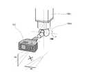
以下、図1ないし図3を参照しつつ本発明の第1実施形態について詳細に説明する。本実施形態の非接触センサ用回転ユニット1は、一方向に走査可能な非接触センサ2と当該非接触センサ2を支持する支持手段3との間に配設され、非接触センサ2の走査方向に対して90度回転可能となっていることを特徴とする。 Hereinafter, a first embodiment of the present invention will be described in detail with reference to FIGS. 1 to 3. The rotation unit 1 for a non-contact sensor according to the present embodiment is disposed between a
図1及び図2に示すように、3次元測定器において、支持手段3は、3軸構成の支持部材3a、3b、3cと、支持部材3cの先端部に設けられている回転2軸ジョイント3dとから構成されている。図示するように支持部材3a、3b、3cはそれぞれXYZの3軸に沿って移動可能に構成されており、また、回転2軸ジョイント3dはA軸とB軸の2軸の回転軸を有する。そして、支持部材3a、3b、3cと回転2軸ジョイント3dとが協働することにより、被測定物に対し非接触センサ2を自由な位置において支持することができる。 As shown in FIGS. 1 and 2, in the three-dimensional measuring instrument, the support means 3 includes
非接触センサ2は、非接触センサ用回転ユニット1と係合するためのジョイント部2aを有している。この非接触センサ2は、出射したレーザ光を一方向に走査させ、レーザ光の戻り光の受光位置の変位を検出し、被測定物の表面形状を取得するセンサである。即ち、一方向にレーザ光を走査することにより完了する1回の走査範囲は直線状となる。そして、この直線状のレーザ光の走査範囲を少しずつ平行にずらすように非接触センサ2を徐々に移動させ、被測定物の表面形状の3次元マップを取得してゆく。 The
非接触センサ用回転ユニット1は、回転2軸ジョイント3dの先端部と非接触センサ2のジョイント部2aとの間に配設されている。この非接触センサ用回転ユニット1は、図3(A)に示すように、外カバー11、波ワッシャ12、第1ジョイント13、カム板14、ディレイ板15、レバー部材16、内カバー17、第2ジョイント18の各部材から構成されている。第1ジョイント13は、回転2軸ジョイント3dの先端部と係合可能となっており、また、第2ジョイント18は、非接触センサ2のジョイント部2aと係合可能となっている。外カバー11、第1ジョイント13、及び内カバー17の各部材は互いに固定され第1部材を構成し、また、カム板14、ディレイ板15、レバー部材16、及び第2ジョイント18の各部材は固定され第2部材を構成している。そして、非接触センサ用回転ユニット1の回転は、第1部材に対して第2部材が90度回転することにより実行される。 The non-contact sensor rotating unit 1 is disposed between the tip of the rotating
第1ジョイント13は120度の角度で離間して形成されている3個の半球状の突起13aを有しており、また、カム板14は、図3(B)に示すように、それぞれ2列の突起から形成されると共に120度の角度で離間して形成されている3つの第1列状突起14aと、第1列状突起14aに対して90度ずれた位置にそれぞれ形成されている3つの第2列状突起14bとを有している。これら突起13a、第1列状突起14a、及び、第2列状突起14bは、非接触センサ用回転ユニット1の少なくとも0度と90度の回転状態を維持するための位置決め手段を構成している。 The first joint 13 has three
第1ジョイント13は波ワッシャ12によって付勢されているため、各突起13aは、第1列状突起14a及び第2列状突起14bの方向へ付勢されている。図3(B)に示されている状態では、各突起13aは各第1列状突起14aによって係止されており、第1ジョイント13はカム板14に対して第1位置(0度の位置)において係止されることになる。また、各突起13aが各第2列状突起14bによって係止されている位置が第2位置(90度の位置)となる。第1位置又は第2位置において、各突起13aは第1列状突起14a又は第2列状突起14bの何れかに係止され、その際、波ワッシャ12の付勢力により第1ジョイント13はカム板14に対してしっかりと3点支持されることになる。 Since the first joint 13 is urged by the
レバー部材16は一対のレバー16aを有し、図2に示すように、このレバー16aは非接触センサ用回転ユニット1の側方から突出している。このレバー16aは、非接触センサ2と別置されている回転補助治具4のU字型の一対の腕部4aの係合溝4bのそれぞれと係合可能となっている。 The
以下、各突起13aが各第1列状突起14aによって第1位置に係止されている状態の非接触センサ用回転ユニット1を回転させ、各突起13aが各第2列状突起14bによって第2位置に係止されている状態へ変更する作業について説明する。 Thereafter, the non-contact sensor rotating unit 1 in a state where each
最初に、支持手段3の支持部材3a、3b、3c及び回転2軸ジョイント3dを操作し、非接触センサ用回転ユニット1のレバー部材16のレバー16aのそれぞれが、回転補助治具4のU字型の一対の腕部4aの係合溝4bのそれぞれと係合する位置へ非接触センサ用回転ユニット1を移動する。 First, the
レバー16aと係合溝4bとを係合させた後、回転2軸ジョイント3dを操作し、そのB軸を中心にして90度回転させる。この90度の回転は図3(B)において反時計回り方向の回転であり、非接触センサ用回転ユニット1の各突起13aが各第1列状突起14aから離脱し、各突起13aが各第2列状突起14bに係止される。即ち、回転2軸ジョイント3dのB軸の回転力により、第1ジョイント13のカム板14に対する位置は、第1位置から第2位置へと変位することになる。そして、第2位置においても波ワッシャ12の付勢力により第1ジョイント13はカム板14に対してしっかりと3点支持される。 After engaging the
第1ジョイント13のカム板14に対する位置が第1位置から第2位置へと変位することにより、非接触センサ2が90度回転し、この非接触センサ2の回転によって、当該センサの走査範囲の方向が90度回転することができる。 When the position of the first joint 13 with respect to the
なお、各突起13aが各第2列状突起14bによって第2位置に係止されている状態の非接触センサ用回転ユニット1を回転させ、各突起13aが各第2列状突起14aによって第1位置に係止されている状態へ変更する作業も、上記のようにレバー16aを係合溝4bに係合し、回転2軸ジョイント3dを操作することにより実行できる。なお、この90度の回転は図3(B)において時計回り方向への回転となる。 Note that the non-contact sensor rotation unit 1 in a state where each
本実施形態の非接触センサ用回転ユニット1は、第1位置及び第2位置のいずれの位置においても波ワッシャ12の付勢力により第1ジョイント13はカム板14に対してしっかりと3点支持されている。従って、レバー16aを手動で操作して、非接触センサ用回転ユニット1を回転することも可能である。 In the non-contact sensor rotation unit 1 of the present embodiment, the first joint 13 is firmly supported by the
本実施形態の非接触センサ用回転ユニット1は、機械式の非接触センサ用回転ユニットの一例にすぎない。例えば、第1部材と第2部材の係合手段は、0度と90度の回転位置を規制できるのであれば、その構成は問わない。また、第1部材と第2部材間の付勢を行えるのであれば、波ワッシャのような部品である必要はない。また、第1部材と第2部材の係合手段は、係合状態において3点支持構造が理想的であるものの、3点支持構造以外の構造を採ることも可能である。 The non-contact sensor rotation unit 1 of this embodiment is merely an example of a mechanical non-contact sensor rotation unit. For example, the configuration of the engaging means of the first member and the second member is not limited as long as the rotation position of 0 degrees and 90 degrees can be regulated. Moreover, if it can energize between a 1st member and a 2nd member, it does not need to be components like a wave washer. In addition, the engaging means for the first member and the second member can adopt a structure other than the three-point support structure, although the three-point support structure is ideal in the engaged state.
次に、図4を参照しつつ本発明の第2実施形態について詳細に説明する。本実施形態の非接触センサ用回転ユニット5は、超音波振動子51を備えている自動回転ユニットである。この非接触センサ用回転ユニット5は、超音波振動子51、振動可動ロッド52、一対のストッパ53、第1ジョイント54、第2ジョイント55、電気回路基板56、第1軸受け57、第2軸受け58を有している。そして、超音波振動子51及び振動可動ロッド52の両部材が非接触センサ用回転ユニット5を90度回転させるための駆動手段を構成している。なお、第1ジョイント54は、上記第1実施形態において説明した回転2軸ジョイント3dの先端部と係合可能となっており、また、第2ジョイント55は、非接触センサ2のジョイント部2aと係合可能となっている。 Next, a second embodiment of the present invention will be described in detail with reference to FIG. The non-contact sensor rotation unit 5 of the present embodiment is an automatic rotation unit including an
超音波振動子51は第1ジョイント54と機械的に連結されており、一方、振動可動ロッド52は第2ジョイント55と機械的に連結されている。この振動可動ロッド52は円弧状の形態を有し、第2ジョイント55の円周に沿うように配設され、また、90度の間隔を隔てて一対のストッパ53を有している。超音波振動子51は、電気回路基板56から供給される振動電気信号によって駆動されることにより、振動可動ロッド52を回転させることができる。この回転範囲は一対のストッパ53により規制されているため、第1ジョイント54と第2ジョイント55の相対角度は0度又は90度の何れかに決定される。また、当該振動電気信号が停止されると、超音波振動子51によって振動可動ロッド52がロックされるため、超音波振動子51の停止時において、第1ジョイント54と第2ジョイント55とはしっかりと固定され、両部材の間のガタつきが防止される。 The
本実施形態の作用効果は、上記第1実施形態における作用効果と略同様であるが、本実施形態の非接触センサ用回転ユニット5は自動回転ユニットであるため回転補助治具4のような部材を必要としない。また、非接触センサ2の支持手段3の位置制御を行うプログラムに、当該非接触用回転ユニット5の回転状態をプログラミングすることにより、完全に自動化された3次元測定器を実現することができる。 The operational effects of the present embodiment are substantially the same as the operational effects of the first embodiment. However, since the non-contact sensor rotating unit 5 of the present embodiment is an automatic rotating unit, a member such as the rotation assist jig 4 is used. Do not need. Further, by programming the rotational state of the non-contact rotation unit 5 in a program for controlling the position of the support means 3 of the
本実施形態の非接触センサ用回転ユニット5は自動回転ユニットの一例にすぎない。例えば、通常の電動モータと歯車等の組み合わせによっても、0度と90度の回転位置を規制できるものであれば当該自動回転ユニットを構成することが可能である。 The non-contact sensor rotating unit 5 of this embodiment is merely an example of an automatic rotating unit. For example, the automatic rotation unit can be configured as long as the rotation position of 0 degrees and 90 degrees can be regulated by a combination of a normal electric motor and gears.
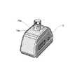
次に、図10を参照しつつ本発明の第3実施形態について詳細に説明する。本実施形態の非接触センサ用回転装置は、第1実施形態における非接触回転ユニット1と、非接触センサ用回転ユニット1を90度回転させるための回転駆動装置6とを有することを特徴とする。 Next, a third embodiment of the present invention will be described in detail with reference to FIG. The non-contact sensor rotation device of the present embodiment includes the non-contact rotation unit 1 in the first embodiment and a
上記第1実施形態において、非接触回転ユニット1は、当該ユニット1の側方から突出しているレバー16aを回転補助治具4の係合溝4bに係合し、回転2軸ジョイント3dのB軸を中心にして90度回転させることにより、非接触センサ2の走査範囲の方向が90度回転するようになっていた。これに対して、本実施形態においては、回転2軸ジョイント3dを回転することなく、回転駆動装置6により非接触センサ2の走査範囲の方向を90度回転させることができる。 In the first embodiment, the non-contact rotation unit 1 engages the
回転駆動装置6は、図10に示すように、本体61と、本体61の上面において回転する回転テーブル62と、回転テーブル62に設けられている1組のアーム63と、本体61に設けられている係止アーム65とを有している。回転テーブル62は、本体61内部に備えられているモータ(図示せず)により90度回転する。 As shown in FIG. 10, the
それぞれのアーム63の先端部には、係止溝64が形成されており、この係止溝64の形状は、非接触回転ユニット1の側方から突出しているレバー16aの形状に対応するようになっている。また、本体61に設けられている係止アーム65の先端部には、非接触回転ユニット1の円筒胴部19を受け入れるための受け入れU字型溝66が形成されている。 A locking
U字型溝66の下方には、非接触センサ2への給電を行うための給電端子(図示せず)が設けられている。この給電端子は、U字型溝66内に非接触回転ユニット1の円筒胴部19が受け入れられた際に、非接触センサ2に設けられている1組の端子19a(図11参照)と電気的に接触することができる。給電端子による非接触センサ2への給電は、当該センサ2を電流により暖気することにより、温度に起因する測定誤差を回避するために行われる。 A power supply terminal (not shown) for supplying power to the
本実施形態において非接触センサ用回転ユニット1を90度回転させる場合には、3次元測定器の支持手段3を制御するプログラムによって、非接触回転ユニット1の側方から突出しているレバー16aに係止され、且つ、非接触回転ユニット1の円筒胴部19が回転駆動装置6のU字型溝66内へ受け入れられるように非接触センサ2を移動する。そして、回転駆動装置6の回転テーブル62を90度回転させることにより、非接触センサ用回転ユニット1を90度回転させる。また、この状態においては、回転駆動装置6に設けられている給電端子により非接触センサ2への給電が可能となる。 In the present embodiment, when the non-contact sensor rotation unit 1 is rotated by 90 degrees, the program for controlling the support means 3 of the three-dimensional measuring instrument is applied to the
上述した3次元測定器の支持手段3を制御するプログラムに回転駆動装置6の回転テーブル62の回転の実行及び停止と給電端子による給電の実行及び停止についてのプログラミングを加えることにより、3次元測定器による測定を自動化することができる。 A program for controlling the support means 3 of the three-dimensional measuring instrument described above is added with programming for execution and stop of rotation of the rotary table 62 of the
1、5 非接触センサ用回転ユニット
2、101 非接触センサ
2a、101a ジョイント部
3、102 支持手段
3a、3b、3c、102a、102b、102c 支持部材
3d、102d 回転2軸ジョイント
4 回転補助治具
4a 腕部
4b 係合溝
6 回転駆動装置
61 本体
62 回転テーブル
63 アーム
64 係止溝
65 係止アーム
66 U字型溝
11 外カバー
12 波ワッシャ
13、54 第1ジョイント
13a 突起
14 カム板
14a 第1列状突起
14b 第2列状突起
15 ディレイ板
16 レバー部材
16a レバー
17 内カバー
18、55 第2ジョイント
19 円筒胴部
19a 端子
51 超音波振動子
52 振動可動ロッド
53 ストッパ
56 電気回路基板
57 第1軸受け
58 第2軸受け
100 三次元測定器1, 5 Non-contact
Claims (7)
Translated fromJapanese前記非接触センサ用回転ユニットを90度回転させるための回転駆動装置とを有することを特徴とする非接触センサ用回転装置。For a non-contact sensor that is disposed between a non-contact sensor that can scan in one direction and a support means that supports the non-contact sensor, and is rotatable by 90 degrees with respect to the scanning direction of the non-contact sensor. A rotating unit;
A non-contact sensor rotating device, comprising: a rotation driving device for rotating the non-contact sensor rotating unit by 90 degrees.
Priority Applications (1)
| Application Number | Priority Date | Filing Date | Title |
|---|---|---|---|
| JP2008184984AJP2009053184A (en) | 2007-07-30 | 2008-07-16 | Rotary unit for noncontact sensor and rotary device for noncontact sensor |
Applications Claiming Priority (2)
| Application Number | Priority Date | Filing Date | Title |
|---|---|---|---|
| JP2007196958 | 2007-07-30 | ||
| JP2008184984AJP2009053184A (en) | 2007-07-30 | 2008-07-16 | Rotary unit for noncontact sensor and rotary device for noncontact sensor |
Publications (1)
| Publication Number | Publication Date |
|---|---|
| JP2009053184Atrue JP2009053184A (en) | 2009-03-12 |
Family
ID=39869674
Family Applications (1)
| Application Number | Title | Priority Date | Filing Date |
|---|---|---|---|
| JP2008184984AWithdrawnJP2009053184A (en) | 2007-07-30 | 2008-07-16 | Rotary unit for noncontact sensor and rotary device for noncontact sensor |
Country Status (2)
| Country | Link |
|---|---|
| JP (1) | JP2009053184A (en) |
| WO (1) | WO2009016185A1 (en) |
Cited By (1)
| Publication number | Priority date | Publication date | Assignee | Title |
|---|---|---|---|---|
| JP2017514119A (en)* | 2014-04-08 | 2017-06-01 | ニコン・メトロロジー・エヌヴェ | Measuring probe unit for measurement |
Families Citing this family (28)
| Publication number | Priority date | Publication date | Assignee | Title |
|---|---|---|---|---|
| DE102006031580A1 (en) | 2006-07-03 | 2008-01-17 | Faro Technologies, Inc., Lake Mary | Method and device for the three-dimensional detection of a spatial area |
| DE102009015920B4 (en) | 2009-03-25 | 2014-11-20 | Faro Technologies, Inc. | Device for optically scanning and measuring an environment |
| US9551575B2 (en) | 2009-03-25 | 2017-01-24 | Faro Technologies, Inc. | Laser scanner having a multi-color light source and real-time color receiver |
| US9529083B2 (en) | 2009-11-20 | 2016-12-27 | Faro Technologies, Inc. | Three-dimensional scanner with enhanced spectroscopic energy detector |
| US9113023B2 (en) | 2009-11-20 | 2015-08-18 | Faro Technologies, Inc. | Three-dimensional scanner with spectroscopic energy detector |
| US8630314B2 (en) | 2010-01-11 | 2014-01-14 | Faro Technologies, Inc. | Method and apparatus for synchronizing measurements taken by multiple metrology devices |
| US9628775B2 (en) | 2010-01-20 | 2017-04-18 | Faro Technologies, Inc. | Articulated arm coordinate measurement machine having a 2D camera and method of obtaining 3D representations |
| US8677643B2 (en) | 2010-01-20 | 2014-03-25 | Faro Technologies, Inc. | Coordinate measurement machines with removable accessories |
| US9607239B2 (en) | 2010-01-20 | 2017-03-28 | Faro Technologies, Inc. | Articulated arm coordinate measurement machine having a 2D camera and method of obtaining 3D representations |
| US8898919B2 (en) | 2010-01-20 | 2014-12-02 | Faro Technologies, Inc. | Coordinate measurement machine with distance meter used to establish frame of reference |
| WO2011090895A1 (en) | 2010-01-20 | 2011-07-28 | Faro Technologies, Inc. | Portable articulated arm coordinate measuring machine with multi-bus arm technology |
| US8875409B2 (en) | 2010-01-20 | 2014-11-04 | Faro Technologies, Inc. | Coordinate measurement machines with removable accessories |
| US8615893B2 (en) | 2010-01-20 | 2013-12-31 | Faro Technologies, Inc. | Portable articulated arm coordinate measuring machine having integrated software controls |
| US8832954B2 (en) | 2010-01-20 | 2014-09-16 | Faro Technologies, Inc. | Coordinate measurement machines with removable accessories |
| US8942940B2 (en) | 2010-01-20 | 2015-01-27 | Faro Technologies, Inc. | Portable articulated arm coordinate measuring machine and integrated electronic data processing system |
| US9163922B2 (en) | 2010-01-20 | 2015-10-20 | Faro Technologies, Inc. | Coordinate measurement machine with distance meter and camera to determine dimensions within camera images |
| US8284407B2 (en) | 2010-01-20 | 2012-10-09 | Faro Technologies, Inc. | Coordinate measuring machine having an illuminated probe end and method of operation |
| DE102010020925B4 (en) | 2010-05-10 | 2014-02-27 | Faro Technologies, Inc. | Method for optically scanning and measuring an environment |
| GB2501390B (en) | 2010-09-08 | 2014-08-06 | Faro Tech Inc | A laser scanner or laser tracker having a projector |
| US9086272B2 (en) | 2010-10-27 | 2015-07-21 | Nikon Corporation | Profile measuring apparatus, method for manufacturing structure, and structure manufacturing system |
| US9168654B2 (en) | 2010-11-16 | 2015-10-27 | Faro Technologies, Inc. | Coordinate measuring machines with dual layer arm |
| DE102012100609A1 (en) | 2012-01-25 | 2013-07-25 | Faro Technologies, Inc. | Device for optically scanning and measuring an environment |
| DE102012103934B3 (en)* | 2012-05-04 | 2013-08-29 | Carl Zeiss Industrielle Messtechnik Gmbh | Optical measuring head for coordinate measuring apparatus, has handle coupled with tubular interface part in selective position, and rod connected to interface part through bolt, which is movably supported in over-sized hole |
| US8997362B2 (en) | 2012-07-17 | 2015-04-07 | Faro Technologies, Inc. | Portable articulated arm coordinate measuring machine with optical communications bus |
| DE102012109481A1 (en) | 2012-10-05 | 2014-04-10 | Faro Technologies, Inc. | Device for optically scanning and measuring an environment |
| US9513107B2 (en) | 2012-10-05 | 2016-12-06 | Faro Technologies, Inc. | Registration calculation between three-dimensional (3D) scans based on two-dimensional (2D) scan data from a 3D scanner |
| DE102015122844A1 (en) | 2015-12-27 | 2017-06-29 | Faro Technologies, Inc. | 3D measuring device with battery pack |
| EP4015986B1 (en)* | 2020-12-18 | 2024-10-16 | TESA Sàrl | Contactless sensor unit for a coordinate measuring machine |
Family Cites Families (2)
| Publication number | Priority date | Publication date | Assignee | Title |
|---|---|---|---|---|
| WO2002027270A1 (en)* | 2000-09-28 | 2002-04-04 | Carl Zeiss | Co-ordinate measuring device |
| DE10260670B4 (en)* | 2002-12-23 | 2007-04-05 | Carl Zeiss Industrielle Messtechnik Gmbh | Device for optically scanning workpieces |
- 2008
- 2008-07-16JPJP2008184984Apatent/JP2009053184A/ennot_activeWithdrawn
- 2008-07-29WOPCT/EP2008/059952patent/WO2009016185A1/enactiveApplication Filing
Cited By (1)
| Publication number | Priority date | Publication date | Assignee | Title |
|---|---|---|---|---|
| JP2017514119A (en)* | 2014-04-08 | 2017-06-01 | ニコン・メトロロジー・エヌヴェ | Measuring probe unit for measurement |
Also Published As
| Publication number | Publication date |
|---|---|
| WO2009016185A1 (en) | 2009-02-05 |
Similar Documents
| Publication | Publication Date | Title |
|---|---|---|
| JP2009053184A (en) | Rotary unit for noncontact sensor and rotary device for noncontact sensor | |
| JP5267722B2 (en) | Laser radar equipment | |
| JP5706158B2 (en) | Surface sensor offset | |
| JP6385463B2 (en) | Object geometric measurement apparatus and method | |
| JP5442457B2 (en) | Locating | |
| US20180128601A1 (en) | Profile measuring apparatus, structure manufacturing system, method for measuring profile, method for manufacturing structure, and non-transitory computer readable medium | |
| JP2006301991A (en) | Correction method of coordinate transformation function | |
| JP4970211B2 (en) | 3D shape measuring instrument | |
| JP2004257927A (en) | Three-dimensional profile measuring system and method for measuring the same | |
| US20130268226A1 (en) | System and Method for Error Correction for CNC Machines | |
| JP6020593B2 (en) | Shape measuring device, structure manufacturing system, stage system, shape measuring method, structure manufacturing method, recording medium recording program | |
| JP2011237425A (en) | Measuring system | |
| JP2017194451A (en) | Error identification method and error identification system for machine tools | |
| JP2010284728A (en) | Conveying robot and automatic teaching method | |
| JP2009014368A (en) | Automatic leveling device for surveying instrument | |
| JP2010190640A (en) | Inclination measuring instrument | |
| US11040443B2 (en) | Rotational angle limiting mechanism | |
| JP2019105481A (en) | Encoder, robot, and measuring method of gap | |
| JP2010117223A (en) | Three-dimensional position measuring apparatus using camera attached on robot | |
| JP2010243219A (en) | Radar device and radar adjusting method | |
| JP6642593B2 (en) | Processing apparatus correction method and processing apparatus | |
| JP7410189B2 (en) | robot calibration device | |
| JP6795911B2 (en) | Measuring method and measuring device | |
| JP5982194B2 (en) | Origin coordinate correction method | |
| JP2010125581A (en) | Gonio stage device |
Legal Events
| Date | Code | Title | Description |
|---|---|---|---|
| A521 | Written amendment | Free format text:JAPANESE INTERMEDIATE CODE: A821 Effective date:20090904 | |
| RD02 | Notification of acceptance of power of attorney | Free format text:JAPANESE INTERMEDIATE CODE: A7422 Effective date:20090904 | |
| A521 | Written amendment | Free format text:JAPANESE INTERMEDIATE CODE: A821 Effective date:20091028 | |
| RD04 | Notification of resignation of power of attorney | Free format text:JAPANESE INTERMEDIATE CODE: A7424 Effective date:20091028 | |
| RD03 | Notification of appointment of power of attorney | Free format text:JAPANESE INTERMEDIATE CODE: A7423 Effective date:20100907 | |
| RD04 | Notification of resignation of power of attorney | Free format text:JAPANESE INTERMEDIATE CODE: A7424 Effective date:20100908 | |
| A521 | Written amendment | Free format text:JAPANESE INTERMEDIATE CODE: A523 Effective date:20100930 | |
| A300 | Withdrawal of application because of no request for examination | Free format text:JAPANESE INTERMEDIATE CODE: A300 Effective date:20111004 |