JP2009051292A - Electric steering device - Google Patents
Electric steering deviceDownload PDFInfo
- Publication number
- JP2009051292A JP2009051292AJP2007218294AJP2007218294AJP2009051292AJP 2009051292 AJP2009051292 AJP 2009051292AJP 2007218294 AJP2007218294 AJP 2007218294AJP 2007218294 AJP2007218294 AJP 2007218294AJP 2009051292 AJP2009051292 AJP 2009051292A
- Authority
- JP
- Japan
- Prior art keywords
- steering
- yaw rate
- torque sensor
- assist
- sensor
- Prior art date
- Legal status (The legal status is an assumption and is not a legal conclusion. Google has not performed a legal analysis and makes no representation as to the accuracy of the status listed.)
- Pending
Links
Images


Landscapes
- Steering Control In Accordance With Driving Conditions (AREA)
- Power Steering Mechanism (AREA)
Abstract
Translated fromJapaneseDescription
Translated fromJapaneseこの発明は、電動ステアリング装置に関するものである。 The present invention relates to an electric steering apparatus.
電動ステアリング装置は、ステアリングシャフトに設けたトルクセンサにより運転者がハンドルに付加した操舵トルクを検出し、検出された操舵トルクに応じてアシストモータを制御し、該モータで発生させたアシストトルクをステアリングシャフトあるいはラックに付加することで、運転者のハンドル操作負担を軽減している。 The electric steering device detects a steering torque applied to a steering wheel by a driver using a torque sensor provided on a steering shaft, controls an assist motor according to the detected steering torque, and steers the assist torque generated by the motor. By adding it to the shaft or rack, the driver's handle operation burden is reduced.
したがって、トルクセンサが故障すると適正なアシストトルクを得ることが困難となる。そこで、トルクセンサ故障時にもアシストモータを制御することができる代替制御方法が考えられている。例えば、特許文献1に記載の発明では、ステアリングシステムのいずれか(トルクセンサを含む)に故障が検出された場合に、故障箇所に応じて予め設定された代替信号を設定し、この代替信号を使ってアシストモータを制御することが開示されている。
なお、トルクセンサの故障検出については、例えば、特許文献2に開示されている。
Note that torque sensor failure detection is disclosed, for example, in
しかしながら、従来のトルクセンサ故障時の代替制御方法では、予め設定された代替信号に基づいてアシストモータを制御するので、アシストトルクの大きさや増減に不自然さがあり、トルクセンサ正常時におけるアシストトルクの増減感との違いに、運転者が戸惑う場合があった。 However, in the conventional alternative control method at the time of torque sensor failure, the assist motor is controlled based on a preset alternative signal, so there is an unnatural amount of increase or decrease in the assist torque, and the assist torque when the torque sensor is normal The driver may be confused by the difference between the increase and decrease feeling.
そこで、この発明は、トルクセンサ故障時にも正常時に近い操舵フィーリングを得ることができる電動ステアリング装置を提供するものである。 Accordingly, the present invention provides an electric steering device that can obtain a steering feeling close to normal even when a torque sensor fails.
この発明に係る電動ステアリング装置では、上記課題を解決するために以下の手段を採用した。
請求項1に係る発明は、運転者の操舵をアシストするアシストトルクを発生させるアシストモータ(例えば、後述する実施例におけるアシストモータ10)と、運転者により入力された操舵トルクを検出する操舵トルクセンサ(例えば、後述する実施例における操舵トルクセンサ16)と、車両に発生した実ヨーレートを検出するヨーレートセンサ(例えば、後述する実施例におけるヨーレートセンサ18)と、前記操舵トルクセンサが正常か否かを判定する故障判定手段(例えば、後述する実施例におけるトルクセンサ故障検出部23)と、備え、前記故障判定手段により前記操舵トルクセンサが正常であると判定されたときには、前記操舵トルクセンサの検出値に基づいて前記アシストモータに供給するアシスト電流を制御し、前記故障判定手段により前記操舵トルクセンサが正常でないと判定されたときには、車両の状態情報に基づいて算出される規範ヨーレートと前記ヨーレートセンサにより検出される実ヨーレートとの偏差に基づいて前記アシストモータに供給するアシスト電流を制御することを特徴とする電動ステアリング装置(例えば、後述する実施例における電動ステアリング装置100)である。The electric steering apparatus according to the present invention employs the following means in order to solve the above problems.
The invention according to claim 1 is an assist motor that generates assist torque that assists the driver's steering (for example, assist
請求項1に係る発明によれば、操舵トルクセンサの異常時には、操舵トルクセンサの出力を用いず、ヨーレート偏差に基づいてアシストモータに供給するアシスト電流を制御することができるので、操舵トルクセンサの異常時にも適正な操舵補助力を発生させることができる。また、運転者が操舵補助力を欲しているときに、例えばステアリングホイールの切り増しや切り戻し時に、操舵補助力を発生させることができる。 According to the first aspect of the invention, when the steering torque sensor is abnormal, the assist current supplied to the assist motor can be controlled based on the yaw rate deviation without using the output of the steering torque sensor. Appropriate steering assist force can be generated even in the event of an abnormality. Further, when the driver wants the steering assist force, the steering assist force can be generated, for example, when the steering wheel is increased or decreased.
以下、この発明に係る電動ステアリング装置の実施例を図1から図6の図面を参照して説明する。
初めに、図1を参照して、電動ステアリング装置の構成を説明する。電動ステアリング装置100は、ステアリングホイール2に連結されたステアリングシャフト1を備えている。ステアリングシャフト1は、ステアリングホイール2に一体結合されたメインシャフト3と、ラック&ピニオン機構のピニオン7が設けられたピニオン軸5とが、ユニバーサルジョイント4によって連結されて構成されている。
ピニオン7はピニオン軸5の下端部に設けられており、車幅方向に往復動し得るラック軸8のラック歯8aに噛合し、ラック軸8の両端には、タイロッド9,9を介して転舵輪としての左右の前輪11,11が連係されている。この構成により、ステアリングホイール2の操舵時に通常のラック&ピニオン式の転舵操作が可能であり、前輪11,11を転舵させて車両の向きを変えることができる。ラック軸8とタイロッド9,9は転舵機構を構成する。Embodiments of an electric steering apparatus according to the present invention will be described below with reference to the drawings of FIGS.
First, the configuration of the electric steering apparatus will be described with reference to FIG. The
The pinion 7 is provided at the lower end of the
電動パワーステアリング装置100は、ステアリングホイール2による操舵力を軽減するための操舵補助力を発生させるブラシレスモータからなるアシストモータ10を備えており、アシストモータ10で発生したトルク(アシストトルク)は、減速装置14によって倍力されてピニオン軸5に伝達される。なお、減速装置14は、アシストモータ10の出力軸に設けられたウォームギヤ12と、ピニオン軸5に設けられウォームギヤ12に噛合するウォームホイールギヤ13とからなる。 The electric
アシストモータ10は、モータシャフトの回転角を検出するためのレゾルバ17を備え、検出した回転角に対応する出力信号をステアリング電子制御装置(以下、EPS−ECUと略す)30へ出力する。
前記ラック&ピニオン機構(8a,7)を収容するステアリングギアボックス(図示略)内には、ピニオン軸5に作用する操舵トルクを検出するための操舵トルクセンサ16が設けられており、操舵トルクセンサ16は検出した操舵トルクに対応する出力信号をEPS−ECU30へ出力する。The
A
また、メインシャフト3には、操舵角を検出するための舵角センサ(操舵角検出手段)15が設けられている。さらに、車体の適所には、車両のヨーレートを検出するヨーレートセンサ18と、車速を検出する車速センサ19と、車両の水平方向加速度(横G)を検出する横Gセンサ20と、車両の前後方向加速度(縦G)を検出する縦Gセンサ21が取り付けられている。 The
舵角センサ15は検出した操舵角に対応する出力信号を、ヨーレートセンサ18は検出したヨーレートに対応する出力信号を、車速センサ19は検出した車速に対応した出力信号を、横Gセンサ20は検出した横Gに対応した出力信号を、縦Gセンサ21は検出した縦Gに対応する出力信号を、それぞれ車内ネットワーク(車内LAN)へ出力する。 The
EPS−ECU30や車両挙動安定化電子制御装置(以下、VSA−ECUと略す)50等の車載の電子制御装置は、車内LANを介してそれぞれの制御に必要な信号を選択的に取り込み、必要な処理を行う。
なお、VSA−ECU50は、ブレーキ時の車輪ロックを防ぐABS(アンチロックブレーキシステム)と、加速時などの車輪空転を防ぐTCS(トラクションコントロールシステム)と、旋回時の横すべり抑制を総合的に制御して車両挙動を安定させる電子制御装置である。In-vehicle electronic control devices such as the EPS-
The VSA-ECU 50 comprehensively controls ABS (anti-lock braking system) that prevents wheel lock during braking, TCS (traction control system) that prevents wheel slipping during acceleration, and side-slip suppression during turning. This is an electronic control device that stabilizes the vehicle behavior.
EPS−ECU30は、操舵トルクセンサ16が正常に作動しているときには、レゾルバ17で検出されたアシストモータ10の回転角と、車速センサ19で検出された車速と、操舵トルクセンサ16により検出された操舵トルクに基づいてアシストモータ10に供給すべき目標電流を決定し、アシストモータ10に流れる実電流(アシスト電流)が目標電流と一致するようにPID制御を行うことにより、アシストモータ10のアシスト電流を制御し、出力トルク(操舵補助力)を制御する。
また、EPS−ECU30は、操舵トルクセンサ16の異常時には、規範ヨーレートと実ヨーレートとの偏差(ヨーレート偏差)に基づいてアシストモータ10に供給すべき目標電流を決定し、アシストモータ10に流れる実電流が目標電流と一致するようにPID制御を行うことにより、アシストモータ10の出力トルクを制御し、操舵補助力を制御する。The EPS-
Further, when the
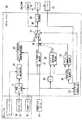
そのため、この電動ステアリング装置100は、図2の制御ブロック図に示すように、操舵トルクセンサ16が正常か否かを判定するトルクセンサ故障検出部(故障判定手段)23と、アシストモータ10に流れる実電流を検出する2つの電流センサ24a,24bを備えている。 Therefore, as shown in the control block diagram of FIG. 2, the
次に、図2の制御ブロック図を参照して、この実施例におけるアシストモータ10に対する電流制御を説明する。
EPS−ECU30は、トルクセンサ故障検出部23と、ベース電流算出部31、イナーシャ補償電流算出部32、ダンパ補償電流算出部33、フィルタ34、回転速度算出部35、加減算器36、切り替え器37、3相dq変換器38、PID制御部39、規範ヨーレート算出部41、ヨーレート偏差算出部42、ヨーレート偏差補償電流算出部43、とを備えている。Next, with reference to the control block diagram of FIG. 2, the current control for the
The EPS-ECU 30 includes a torque sensor
トルクセンサ故障検出部23は、操舵トルクセンサ16の出力信号に基づいて操舵トルクセンサ16が正常か否かを判定し、判定結果に応じた出力信号(正常信号あるいは異常信号)を切り替え器37へ出力する。
ベース電流算出部31は、操舵トルクセンサ16で検出された操舵トルクTおよび車速センサ19で検出された車速Vに基づき、図3に示すベース電流テーブルを参照して、操舵トルクTと車速Vに応じたベース電流DTを算出する(DT=f(T,V))。この実施例のベース電流テーブルは、操舵トルクTが大きくなるにしたがってベース電流DTのゲインが大きくなるように設定されており、また、車速Vが高くなるにしたがってベース電流DTのゲインが小さく且つ不感帯(ゲインがゼロに設定されるトルク域)が大きくなるように設定されている。これにより、車速Vの増大に応じてしっかりとした操舵トルクの手応え感を付与している。The torque sensor
Based on the steering torque T detected by the
また、操舵トルクセンサ16で検出された操舵トルクTはフィルタ34において時間微分され、操舵トルクTの時間微分値F4が算出される。
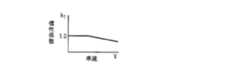
イナーシャ補償電流算出部32は、車速センサ19で検出された車速Vに基づき、図4に示す慣性係数テーブルを参照して車速Vに応じた慣性係数kTを算出し、操舵トルクセンサ16で検出された操舵トルクTと、フィルタ34から出力される操舵トルクTの時間微分値F4と、慣性係数kTとを乗じてイナーシャ補償電流DTDを算出する(DTD=T・F4・kT)。このイナーシャ補償電流DTDは、アシストモータ10およびステアリングシステムの慣性モーメントを打ち消すためのトルクを発生させるものであり、これによりアシストモータ10の応答性を向上させる。この実施例の慣性係数テーブルでは、車速Vが高くなるにしたがって慣性係数kTが小さくなるように設定されている。Further, the steering torque T detected by the
Based on the vehicle speed V detected by the
回転速度算出部35は、レゾルバ17で検出されたアシストモータ10の回転角θを時間微分した値に減速係数kθを乗じてステアリングシャフト1の回転速度Sを算出する(S=kθ・dθ/dt)。
そして、ダンパ補償電流算出部33は、回転速度算出部35で算出された回転速度Sと車速センサ19で検出された車速Vに基づいて、図5に示すダンパ補償電流テーブルを参照して、回転速度Sと車速Vに応じたダンパ補償電流DSを算出する。The rotation
Then, the damper compensation
この実施例のダンパ補償電流テーブルでは、回転速度Sが大きくなるにしたがってダンパ補償電流DSのゲイン(以下、ダンパゲインと略す)が大きくなるように設定されており、また、車速Vが高くなるにしたがってダンパゲインが大きくなるように設定されていて、回転速度Sが大きいほど、車速Vが高いほど大きなダンパ効果が得られるようにしている。これにより、良好な操舵フィールを得ることができ、ステアリングホイール2の収斂性を向上させることができる。The damper compensation current table of this embodiment, the gain of the damper compensation current DS as the rotational speed S increases (hereinafter, referred to as damper gain) is set to increase, also, the vehicle speed V is higher Accordingly, the damper gain is set to be large, and a larger damper effect is obtained as the rotational speed S increases and the vehicle speed V increases. Thereby, a favorable steering feel can be obtained and the convergence of the
加減算器36は、ベース電流算出部31で算出したベース電流DTと、イナーシャ補償電流算出部32で算出したイナーシャ補償電流DTDを加算し、ダンパ補償電流算出部33で算出したダンパ補償電流DSを減算して第1目標電流Dr1を算出し(Dr1=DT+DTD−DS)、切り替え器37へ出力する。この第1目標電流Dr1は、操舵トルクセンサ16が正常なときにアシストモータ10に対する目標電流となる。The adder /
一方、規範ヨーレート算出部41は、車速センサ19で検出された車速Vと、舵角センサ15で検出された操舵角αとに基づいて、規範ヨーレートを算出する。ここで、規範ヨーレートは、車速Vと操舵角α(車両の状態情報)に基づいて算出される理想モデル上のヨーレートである。 On the other hand, the reference yaw
ヨーレート偏差算出部42では、規範ヨーレート算出部41で算出された規範ヨーレートから、ヨーレートセンサ18で検出された実ヨーレートを減算して偏差(以下、ヨーレート偏差という)を算出し、ヨーレート偏差補償電流算出部43へ出力する。 The yaw rate
ヨーレート偏差補償電流算出部43では、車速センサ19で検出された車速Vと、ヨーレート偏差算出部42で算出されたヨーレート偏差とに基づいて、図6に示すヨーレート偏差補償電流テーブルを参照して、ヨーレート偏差補償電流DYを算出し、これを第2目標電流Dr2として切り替え器37へ出力する。この第2目標電流Dr2であるヨーレート偏差補償電流DYは、操舵トルクセンサ16が異常のときにアシストモータ10に対する目標電流となる。この実施例のヨーレート偏差補償電流テーブルでは、ヨーレート偏差が大きくなるにしたがってヨーレート偏差補償電流DYが大きくなるように設定されており、また、車速Vが高くなるにしたがってヨーレート偏差補償電流DYが小さくなるように設定されている。The yaw rate deviation compensation
切り替え器37は、トルクセンサ故障検出部23から正常信号を入力したときには、第1目標電流Dr1だけをPID制御部39へ出力して、第2目標電流Dr2を出力しないように制御し、トルクセンサ故障検出部23から異常信号を入力したときには、第2目標電流Dr2だけをPID制御部39へ出力して、第1目標電流Dr1を出力しないように制御する。 When the normal signal is input from the torque sensor
そして、3相dq変換器38は、電流計24a,24bにより検出されたアシストモータ10に流れている実電流とレゾルバ17により検出された回転角により3相からdq変換する。
そして、PID制御部39は、アシストモータ10に流れる交流電流を、切り替え器37から出力される目標電流(第1目標電流Dr1または第2目標電流Dr2)と一致させるようにPID制御を行う。The three-
Then, the
このように構成された電動ステアリング装置100では、操舵トルクセンサ16の異常が検出されたときには、アシストモータ10の目標電流を決定する際に操舵トルクセンサ16の出力を用いないで、ヨーレート偏差に基づいて算出されるヨーレート偏差補償電流DYをアシストモータ10の目標電流として用いて、アシストモータ10のアシスト電流を制御し、出力トルク(操舵補助力)を制御することができるので、操舵トルクセンサ16の故障時にも操舵補助力を付与することができる。In the
そして、規範ヨーレートと実ヨーレートとの偏差であるヨーレート偏差が生じたときに操舵補助力を発生させ、しかも、ヨーレート偏差が大きいほど大きな操舵補助力を発生させることができるので、ステアリングホイール2を操作している運転者が補助して欲しいとき、例えばステアリングホイール2の切り増しや切り戻し時に操舵補助力を発生させることができる。
一方、運転者がステアリングホイール2を保舵しているときには運転者は余り操舵補助を必要としないが、このようなときにはヨーレート偏差が生じないので操舵補助力が発生しない。
したがって、操舵トルクセンサ16の故障時にも、操舵補助力に対する運転者の要望に近い傾向で操舵補助力をステアリングシャフト1に付与することができ、使い勝手がよい。When the yaw rate deviation, which is the deviation between the standard yaw rate and the actual yaw rate, is generated, the steering assist force can be generated, and the greater the yaw rate deviation, the greater the steering assist force can be generated. When a driver who wants to assist the driver wants to assist, for example, the steering assist force can be generated when the
On the other hand, when the driver is holding the
Therefore, even when the
10 アシストモータ
16 操舵トルクセンサ
18 ヨーレートセンサ
23 トルクセンサ故障検出部(故障判定手段)
100 電動ステアリング装置DESCRIPTION OF
100 Electric steering device
Claims (1)
Translated fromJapanese運転者により入力された操舵トルクを検出する操舵トルクセンサと、
車両に発生した実ヨーレートを検出するヨーレートセンサと、
前記操舵トルクセンサが正常か否かを判定する故障判定手段と、
を備え、
前記故障判定手段により前記操舵トルクセンサが正常であると判定されたときには、前記操舵トルクセンサの検出値に基づいて前記アシストモータに供給するアシスト電流を制御し、
前記故障判定手段により前記操舵トルクセンサが正常でないと判定されたときには、車両の状態情報に基づいて算出される規範ヨーレートと前記ヨーレートセンサにより検出される実ヨーレートとの偏差に基づいて前記アシストモータに供給するアシスト電流を制御することを特徴とする電動ステアリング装置。An assist motor for generating an assist torque for assisting a driver's steering;
A steering torque sensor for detecting the steering torque input by the driver;
A yaw rate sensor that detects the actual yaw rate generated in the vehicle;
Failure determination means for determining whether or not the steering torque sensor is normal;
With
When the failure determination means determines that the steering torque sensor is normal, the assist current supplied to the assist motor is controlled based on the detected value of the steering torque sensor,
When the failure determination means determines that the steering torque sensor is not normal, the assist motor is controlled based on a deviation between a standard yaw rate calculated based on vehicle state information and an actual yaw rate detected by the yaw rate sensor. An electric steering apparatus for controlling an assist current to be supplied.
Priority Applications (1)
| Application Number | Priority Date | Filing Date | Title |
|---|---|---|---|
| JP2007218294AJP2009051292A (en) | 2007-08-24 | 2007-08-24 | Electric steering device |
Applications Claiming Priority (1)
| Application Number | Priority Date | Filing Date | Title |
|---|---|---|---|
| JP2007218294AJP2009051292A (en) | 2007-08-24 | 2007-08-24 | Electric steering device |
Publications (1)
| Publication Number | Publication Date |
|---|---|
| JP2009051292Atrue JP2009051292A (en) | 2009-03-12 |
Family
ID=40502784
Family Applications (1)
| Application Number | Title | Priority Date | Filing Date |
|---|---|---|---|
| JP2007218294APendingJP2009051292A (en) | 2007-08-24 | 2007-08-24 | Electric steering device |
Country Status (1)
| Country | Link |
|---|---|
| JP (1) | JP2009051292A (en) |
Cited By (12)
| Publication number | Priority date | Publication date | Assignee | Title |
|---|---|---|---|---|
| JP2010221944A (en)* | 2009-03-25 | 2010-10-07 | Honda Motor Co Ltd | Vehicle behavior control device |
| EP2799310A1 (en)* | 2013-04-30 | 2014-11-05 | Steering Solutions IP Holding Corporation | Providing assist torque without hand wheel torque sensor |
| EP3006306A1 (en)* | 2014-09-15 | 2016-04-13 | Steering Solutions IP Holding Corporation | Providing assist torque without hand wheel torque sensor for zero to low vehicle speeds |
| US9540040B2 (en) | 2014-06-26 | 2017-01-10 | Steering Solutions Ip Holding Corporation | Phase plane based transitional damping for electric power steering |
| US9540044B2 (en) | 2013-11-15 | 2017-01-10 | Steering Solutions Ip Holding Corporation | Hand wheel angle from vehicle dynamic sensors or wheel speeds |
| US9676409B2 (en) | 2013-03-11 | 2017-06-13 | Steering Solutions Ip Holding Corporation | Road wheel disturbance rejection based on hand wheel acceleration |
| US10144445B2 (en) | 2014-09-15 | 2018-12-04 | Steering Solutions Ip Holding Corporation | Modified static tire model for providing assist without a torque sensor for zero to low vehicle speeds |
| US10155534B2 (en) | 2016-06-14 | 2018-12-18 | Steering Solutions Ip Holding Corporation | Driver intent estimation without using torque sensor signal |
| US10166977B2 (en)* | 2014-09-24 | 2019-01-01 | Hitachi Automotive Systems, Ltd. | Control apparatus for vehicle-mounted apparatus and power steering apparatus |
| US10336363B2 (en) | 2015-09-03 | 2019-07-02 | Steering Solutions Ip Holding Corporation | Disabling controlled velocity return based on torque gradient and desired velocity error |
| US10377415B2 (en) | 2016-10-19 | 2019-08-13 | Hyundai Motor Company | Method of controlling motor driven power steering system |
| US10464594B2 (en) | 2015-09-03 | 2019-11-05 | Steering Solutions Ip Holding Corporation | Model based driver torque estimation |
Citations (9)
| Publication number | Priority date | Publication date | Assignee | Title |
|---|---|---|---|---|
| JPH0834360A (en)* | 1994-07-25 | 1996-02-06 | Honda Motor Co Ltd | Vehicle steering system |
| JP2004050972A (en)* | 2002-07-19 | 2004-02-19 | Mitsubishi Motors Corp | Electric power steering device |
| JP2004338562A (en)* | 2003-05-15 | 2004-12-02 | Toyoda Mach Works Ltd | Electric power steering controller |
| JP2005255107A (en)* | 2004-03-15 | 2005-09-22 | Toyota Motor Corp | Vehicle behavior control device |
| JP2005254902A (en)* | 2004-03-10 | 2005-09-22 | Toyota Motor Corp | Vehicle steering device |
| JP2005343300A (en)* | 2004-06-02 | 2005-12-15 | Toyota Motor Corp | Driving assistance device |
| JP2006151071A (en)* | 2004-11-26 | 2006-06-15 | Toyota Motor Corp | Device for determining vehicle turning travel assist yaw moment |
| JP2006297983A (en)* | 2005-04-15 | 2006-11-02 | Honda Motor Co Ltd | Steering operation support device |
| JP2007039017A (en)* | 2005-06-28 | 2007-02-15 | Honda Motor Co Ltd | Vehicle operation support device |
- 2007
- 2007-08-24JPJP2007218294Apatent/JP2009051292A/enactivePending
Patent Citations (9)
| Publication number | Priority date | Publication date | Assignee | Title |
|---|---|---|---|---|
| JPH0834360A (en)* | 1994-07-25 | 1996-02-06 | Honda Motor Co Ltd | Vehicle steering system |
| JP2004050972A (en)* | 2002-07-19 | 2004-02-19 | Mitsubishi Motors Corp | Electric power steering device |
| JP2004338562A (en)* | 2003-05-15 | 2004-12-02 | Toyoda Mach Works Ltd | Electric power steering controller |
| JP2005254902A (en)* | 2004-03-10 | 2005-09-22 | Toyota Motor Corp | Vehicle steering device |
| JP2005255107A (en)* | 2004-03-15 | 2005-09-22 | Toyota Motor Corp | Vehicle behavior control device |
| JP2005343300A (en)* | 2004-06-02 | 2005-12-15 | Toyota Motor Corp | Driving assistance device |
| JP2006151071A (en)* | 2004-11-26 | 2006-06-15 | Toyota Motor Corp | Device for determining vehicle turning travel assist yaw moment |
| JP2006297983A (en)* | 2005-04-15 | 2006-11-02 | Honda Motor Co Ltd | Steering operation support device |
| JP2007039017A (en)* | 2005-06-28 | 2007-02-15 | Honda Motor Co Ltd | Vehicle operation support device |
Cited By (15)
| Publication number | Priority date | Publication date | Assignee | Title |
|---|---|---|---|---|
| JP2010221944A (en)* | 2009-03-25 | 2010-10-07 | Honda Motor Co Ltd | Vehicle behavior control device |
| US9676409B2 (en) | 2013-03-11 | 2017-06-13 | Steering Solutions Ip Holding Corporation | Road wheel disturbance rejection based on hand wheel acceleration |
| EP2799310A1 (en)* | 2013-04-30 | 2014-11-05 | Steering Solutions IP Holding Corporation | Providing assist torque without hand wheel torque sensor |
| CN104129425A (en)* | 2013-04-30 | 2014-11-05 | 操纵技术Ip控股公司 | Providing assist torque without hand wheel torque sensor |
| US10155531B2 (en) | 2013-04-30 | 2018-12-18 | Steering Solutions Ip Holding Corporation | Providing assist torque without hand wheel torque sensor |
| US9540044B2 (en) | 2013-11-15 | 2017-01-10 | Steering Solutions Ip Holding Corporation | Hand wheel angle from vehicle dynamic sensors or wheel speeds |
| US9540040B2 (en) | 2014-06-26 | 2017-01-10 | Steering Solutions Ip Holding Corporation | Phase plane based transitional damping for electric power steering |
| EP3006306A1 (en)* | 2014-09-15 | 2016-04-13 | Steering Solutions IP Holding Corporation | Providing assist torque without hand wheel torque sensor for zero to low vehicle speeds |
| US10144445B2 (en) | 2014-09-15 | 2018-12-04 | Steering Solutions Ip Holding Corporation | Modified static tire model for providing assist without a torque sensor for zero to low vehicle speeds |
| US9409595B2 (en) | 2014-09-15 | 2016-08-09 | Steering Solutions Ip Holding Corporation | Providing assist torque without hand wheel torque sensor for zero to low vehicle speeds |
| US10166977B2 (en)* | 2014-09-24 | 2019-01-01 | Hitachi Automotive Systems, Ltd. | Control apparatus for vehicle-mounted apparatus and power steering apparatus |
| US10336363B2 (en) | 2015-09-03 | 2019-07-02 | Steering Solutions Ip Holding Corporation | Disabling controlled velocity return based on torque gradient and desired velocity error |
| US10464594B2 (en) | 2015-09-03 | 2019-11-05 | Steering Solutions Ip Holding Corporation | Model based driver torque estimation |
| US10155534B2 (en) | 2016-06-14 | 2018-12-18 | Steering Solutions Ip Holding Corporation | Driver intent estimation without using torque sensor signal |
| US10377415B2 (en) | 2016-10-19 | 2019-08-13 | Hyundai Motor Company | Method of controlling motor driven power steering system |
Similar Documents
| Publication | Publication Date | Title |
|---|---|---|
| JP2009051292A (en) | Electric steering device | |
| US10703405B2 (en) | Steering control device | |
| US7909131B2 (en) | Electric power steering apparatus | |
| US7828112B2 (en) | Electric power steering device | |
| JP4561806B2 (en) | Electric power steering device | |
| JP6380014B2 (en) | Electric power steering device | |
| WO2014162769A1 (en) | Electric power steering device | |
| JP5994481B2 (en) | Electric power steering device | |
| JP2017149359A (en) | Steering control device | |
| JP2006151360A (en) | Vehicle steering system | |
| JP2019131014A (en) | Steering control device | |
| JP2009269540A (en) | Electric power steering device | |
| JP2010162954A (en) | Electric power steering device | |
| JP2014054885A (en) | Electric power steering device | |
| JP4969368B2 (en) | Control method of electric steering device | |
| JP4957022B2 (en) | Vehicle steering control device | |
| JP2008230580A (en) | Electric power steering device | |
| JP2010254096A (en) | Electric power steering device | |
| JP4377750B2 (en) | Vehicle steering device | |
| JP2010274871A (en) | Vehicle steering system | |
| JP2014141129A (en) | Electric power steering system | |
| JP2008068663A (en) | Control device for electric power steering device | |
| JP2016159868A (en) | Automatic driving device | |
| JP2006256425A (en) | Steering device | |
| JP2008254522A (en) | Steering device |
Legal Events
| Date | Code | Title | Description |
|---|---|---|---|
| A621 | Written request for application examination | Effective date:20091127 Free format text:JAPANESE INTERMEDIATE CODE: A621 | |
| A977 | Report on retrieval | Effective date:20110624 Free format text:JAPANESE INTERMEDIATE CODE: A971007 | |
| A131 | Notification of reasons for refusal | Effective date:20110802 Free format text:JAPANESE INTERMEDIATE CODE: A131 | |
| A02 | Decision of refusal | Effective date:20120124 Free format text:JAPANESE INTERMEDIATE CODE: A02 |