JP2009050701A - Dialogue image system, dialogue apparatus and operation control method thereof - Google Patents
Dialogue image system, dialogue apparatus and operation control method thereofDownload PDFInfo
- Publication number
- JP2009050701A JP2009050701AJP2008212786AJP2008212786AJP2009050701AJP 2009050701 AJP2009050701 AJP 2009050701AJP 2008212786 AJP2008212786 AJP 2008212786AJP 2008212786 AJP2008212786 AJP 2008212786AJP 2009050701 AJP2009050701 AJP 2009050701A
- Authority
- JP
- Japan
- Prior art keywords
- image
- interactive
- module
- reference point
- host
- Prior art date
- Legal status (The legal status is an assumption and is not a legal conclusion. Google has not performed a legal analysis and makes no representation as to the accuracy of the status listed.)
- Granted
Links
Images


Classifications
- G—PHYSICS
- G06—COMPUTING OR CALCULATING; COUNTING
- G06F—ELECTRIC DIGITAL DATA PROCESSING
- G06F3/00—Input arrangements for transferring data to be processed into a form capable of being handled by the computer; Output arrangements for transferring data from processing unit to output unit, e.g. interface arrangements
- G06F3/01—Input arrangements or combined input and output arrangements for interaction between user and computer
- G06F3/03—Arrangements for converting the position or the displacement of a member into a coded form
- G06F3/033—Pointing devices displaced or positioned by the user, e.g. mice, trackballs, pens or joysticks; Accessories therefor
- G06F3/0346—Pointing devices displaced or positioned by the user, e.g. mice, trackballs, pens or joysticks; Accessories therefor with detection of the device orientation or free movement in a 3D space, e.g. 3D mice, 6-DOF [six degrees of freedom] pointers using gyroscopes, accelerometers or tilt-sensors
- A—HUMAN NECESSITIES
- A63—SPORTS; GAMES; AMUSEMENTS
- A63F—CARD, BOARD, OR ROULETTE GAMES; INDOOR GAMES USING SMALL MOVING PLAYING BODIES; VIDEO GAMES; GAMES NOT OTHERWISE PROVIDED FOR
- A63F13/00—Video games, i.e. games using an electronically generated display having two or more dimensions
- A63F13/20—Input arrangements for video game devices
- A63F13/23—Input arrangements for video game devices for interfacing with the game device, e.g. specific interfaces between game controller and console
- A63F13/235—Input arrangements for video game devices for interfacing with the game device, e.g. specific interfaces between game controller and console using a wireless connection, e.g. infrared or piconet
- A—HUMAN NECESSITIES
- A63—SPORTS; GAMES; AMUSEMENTS
- A63F—CARD, BOARD, OR ROULETTE GAMES; INDOOR GAMES USING SMALL MOVING PLAYING BODIES; VIDEO GAMES; GAMES NOT OTHERWISE PROVIDED FOR
- A63F13/00—Video games, i.e. games using an electronically generated display having two or more dimensions
- A63F13/20—Input arrangements for video game devices
- A63F13/21—Input arrangements for video game devices characterised by their sensors, purposes or types
- A63F13/211—Input arrangements for video game devices characterised by their sensors, purposes or types using inertial sensors, e.g. accelerometers or gyroscopes
- A—HUMAN NECESSITIES
- A63—SPORTS; GAMES; AMUSEMENTS
- A63F—CARD, BOARD, OR ROULETTE GAMES; INDOOR GAMES USING SMALL MOVING PLAYING BODIES; VIDEO GAMES; GAMES NOT OTHERWISE PROVIDED FOR
- A63F13/00—Video games, i.e. games using an electronically generated display having two or more dimensions
- A63F13/20—Input arrangements for video game devices
- A63F13/21—Input arrangements for video game devices characterised by their sensors, purposes or types
- A63F13/213—Input arrangements for video game devices characterised by their sensors, purposes or types comprising photodetecting means, e.g. cameras, photodiodes or infrared cells
- A—HUMAN NECESSITIES
- A63—SPORTS; GAMES; AMUSEMENTS
- A63F—CARD, BOARD, OR ROULETTE GAMES; INDOOR GAMES USING SMALL MOVING PLAYING BODIES; VIDEO GAMES; GAMES NOT OTHERWISE PROVIDED FOR
- A63F13/00—Video games, i.e. games using an electronically generated display having two or more dimensions
- A63F13/40—Processing input control signals of video game devices, e.g. signals generated by the player or derived from the environment
- A63F13/42—Processing input control signals of video game devices, e.g. signals generated by the player or derived from the environment by mapping the input signals into game commands, e.g. mapping the displacement of a stylus on a touch screen to the steering angle of a virtual vehicle
- A63F13/422—Processing input control signals of video game devices, e.g. signals generated by the player or derived from the environment by mapping the input signals into game commands, e.g. mapping the displacement of a stylus on a touch screen to the steering angle of a virtual vehicle automatically for the purpose of assisting the player, e.g. automatic braking in a driving game
- H—ELECTRICITY
- H04—ELECTRIC COMMUNICATION TECHNIQUE
- H04N—PICTORIAL COMMUNICATION, e.g. TELEVISION
- H04N21/00—Selective content distribution, e.g. interactive television or video on demand [VOD]
- H04N21/40—Client devices specifically adapted for the reception of or interaction with content, e.g. set-top-box [STB]; Operations thereof
- H04N21/41—Structure of client; Structure of client peripherals
- H04N21/414—Specialised client platforms, e.g. receiver in car or embedded in a mobile appliance
- H04N21/4143—Specialised client platforms, e.g. receiver in car or embedded in a mobile appliance embedded in a Personal Computer [PC]
- H—ELECTRICITY
- H04—ELECTRIC COMMUNICATION TECHNIQUE
- H04N—PICTORIAL COMMUNICATION, e.g. TELEVISION
- H04N21/00—Selective content distribution, e.g. interactive television or video on demand [VOD]
- H04N21/40—Client devices specifically adapted for the reception of or interaction with content, e.g. set-top-box [STB]; Operations thereof
- H04N21/41—Structure of client; Structure of client peripherals
- H04N21/422—Input-only peripherals, i.e. input devices connected to specially adapted client devices, e.g. global positioning system [GPS]
- H04N21/42204—User interfaces specially adapted for controlling a client device through a remote control device; Remote control devices therefor
- H04N21/42206—User interfaces specially adapted for controlling a client device through a remote control device; Remote control devices therefor characterized by hardware details
- H04N21/42222—Additional components integrated in the remote control device, e.g. timer, speaker, sensors for detecting position, direction or movement of the remote control, microphone or battery charging device
- A—HUMAN NECESSITIES
- A63—SPORTS; GAMES; AMUSEMENTS
- A63F—CARD, BOARD, OR ROULETTE GAMES; INDOOR GAMES USING SMALL MOVING PLAYING BODIES; VIDEO GAMES; GAMES NOT OTHERWISE PROVIDED FOR
- A63F2300/00—Features of games using an electronically generated display having two or more dimensions, e.g. on a television screen, showing representations related to the game
- A63F2300/10—Features of games using an electronically generated display having two or more dimensions, e.g. on a television screen, showing representations related to the game characterized by input arrangements for converting player-generated signals into game device control signals
- A63F2300/1025—Features of games using an electronically generated display having two or more dimensions, e.g. on a television screen, showing representations related to the game characterized by input arrangements for converting player-generated signals into game device control signals details of the interface with the game device, e.g. USB version detection
- A63F2300/1031—Features of games using an electronically generated display having two or more dimensions, e.g. on a television screen, showing representations related to the game characterized by input arrangements for converting player-generated signals into game device control signals details of the interface with the game device, e.g. USB version detection using a wireless connection, e.g. Bluetooth, infrared connections
- A—HUMAN NECESSITIES
- A63—SPORTS; GAMES; AMUSEMENTS
- A63F—CARD, BOARD, OR ROULETTE GAMES; INDOOR GAMES USING SMALL MOVING PLAYING BODIES; VIDEO GAMES; GAMES NOT OTHERWISE PROVIDED FOR
- A63F2300/00—Features of games using an electronically generated display having two or more dimensions, e.g. on a television screen, showing representations related to the game
- A63F2300/10—Features of games using an electronically generated display having two or more dimensions, e.g. on a television screen, showing representations related to the game characterized by input arrangements for converting player-generated signals into game device control signals
- A63F2300/105—Features of games using an electronically generated display having two or more dimensions, e.g. on a television screen, showing representations related to the game characterized by input arrangements for converting player-generated signals into game device control signals using inertial sensors, e.g. accelerometers, gyroscopes
- A—HUMAN NECESSITIES
- A63—SPORTS; GAMES; AMUSEMENTS
- A63F—CARD, BOARD, OR ROULETTE GAMES; INDOOR GAMES USING SMALL MOVING PLAYING BODIES; VIDEO GAMES; GAMES NOT OTHERWISE PROVIDED FOR
- A63F2300/00—Features of games using an electronically generated display having two or more dimensions, e.g. on a television screen, showing representations related to the game
- A63F2300/10—Features of games using an electronically generated display having two or more dimensions, e.g. on a television screen, showing representations related to the game characterized by input arrangements for converting player-generated signals into game device control signals
- A63F2300/1087—Features of games using an electronically generated display having two or more dimensions, e.g. on a television screen, showing representations related to the game characterized by input arrangements for converting player-generated signals into game device control signals comprising photodetecting means, e.g. a camera
- A—HUMAN NECESSITIES
- A63—SPORTS; GAMES; AMUSEMENTS
- A63F—CARD, BOARD, OR ROULETTE GAMES; INDOOR GAMES USING SMALL MOVING PLAYING BODIES; VIDEO GAMES; GAMES NOT OTHERWISE PROVIDED FOR
- A63F2300/00—Features of games using an electronically generated display having two or more dimensions, e.g. on a television screen, showing representations related to the game
- A63F2300/60—Methods for processing data by generating or executing the game program
- A63F2300/6045—Methods for processing data by generating or executing the game program for mapping control signals received from the input arrangement into game commands
- H—ELECTRICITY
- H04—ELECTRIC COMMUNICATION TECHNIQUE
- H04N—PICTORIAL COMMUNICATION, e.g. TELEVISION
- H04N21/00—Selective content distribution, e.g. interactive television or video on demand [VOD]
- H04N21/40—Client devices specifically adapted for the reception of or interaction with content, e.g. set-top-box [STB]; Operations thereof
- H04N21/41—Structure of client; Structure of client peripherals
- H04N21/422—Input-only peripherals, i.e. input devices connected to specially adapted client devices, e.g. global positioning system [GPS]
- H04N21/42204—User interfaces specially adapted for controlling a client device through a remote control device; Remote control devices therefor
- H04N21/42206—User interfaces specially adapted for controlling a client device through a remote control device; Remote control devices therefor characterized by hardware details
Landscapes
- Engineering & Computer Science (AREA)
- Multimedia (AREA)
- Human Computer Interaction (AREA)
- Signal Processing (AREA)
- General Engineering & Computer Science (AREA)
- Theoretical Computer Science (AREA)
- Computer Networks & Wireless Communication (AREA)
- Physics & Mathematics (AREA)
- General Physics & Mathematics (AREA)
- Position Input By Displaying (AREA)
- Image Analysis (AREA)
- User Interface Of Digital Computer (AREA)
Abstract
Translated fromJapaneseDescription
Translated fromJapanese本発明は、対話画像システム、対話装置及びその運転制御方法に関し、特に、対話装置の画像モジュールのサンプリング周波数を変調することにより消費電力を低減する対話画像システム、対話装置及びその運転制御方法に関する。 The present invention relates to an interactive image system, an interactive apparatus, and an operation control method thereof, and more particularly to an interactive image system, an interactive apparatus, and an operation control method thereof that reduce power consumption by modulating a sampling frequency of an image module of the interactive apparatus.
本願発明は、ここに参照して本明細書に援用する2007年8月23日出願の台湾特許出願第096131177号における全開示内容に対して優先権を主張するものである。 The present invention claims priority to all disclosures in Taiwan Patent Application No. 096131177 filed on August 23, 2007, which is incorporated herein by reference.
従来のゲームリモート装置、例えば特許文献1記載のポインタ位置決め装置は光線銃ゲームに応用することができる。該ポインタ位置決め装置のカメラポインタ装置には、カメラと、計算ユニットと、通信インタフェースとを接続する制御回路が設置されている。通信インタフェースはホストに接続される。カメラには光学フィルタが設けられており、またスクリーンにはカメラで撮像するための複数の発光素子が設けられている。使用者がカメラポインタ装置を使ってホストのプログラムを実行する場合、カメラによりスクリーンを撮像し、またカメラには発光素子から生成される光の波長帯域以外の光を遮断できる光学フィルタが設けられているため、カメラが撮像した画像は発光素子のイメージのみを含む。計算ユニットがこの画像に基づきカメラの照準点の座標値を算出してホストに送信する。そしてホストがこの座標値に基づいて相関制御を行う。 A conventional game remote device, such as the pointer positioning device described in Patent Document 1, can be applied to a light gun game. The camera pointer device of the pointer positioning device is provided with a control circuit for connecting the camera, the calculation unit, and the communication interface. The communication interface is connected to the host. The camera is provided with an optical filter, and the screen is provided with a plurality of light emitting elements for imaging with the camera. When a user executes a host program using a camera pointer device, the camera is imaged on the screen, and the camera is provided with an optical filter capable of blocking light other than the wavelength band of light generated from the light emitting element. Therefore, the image captured by the camera includes only the image of the light emitting element. The calculation unit calculates the coordinate value of the aiming point of the camera based on this image and transmits it to the host. Then, the host performs correlation control based on the coordinate values.
しかし、実際の使用において、リモート装置(リモートコントローラ)の操作の利便性を向上させるために、リモート装置が無線通信によりホストと通信し、かつ電池モジュールによりリモート装置が必要とする消費電力を提供する。リモート装置は複数の電力を消費する素子を有するため、各素子の消費電力をできるだけ低減する必要があり、これは電池モジュールの寿命を延ばすためである。一般に、計算ユニットが算出した照準点の座標値の正確性を高めるため、カメラについては、より高いサンプリング周波数で撮像することが好ましい。しかし、サンプリング周波数が高くなるほど、計算ユニットの計算負荷が増え、これに伴ってリモート装置の消費電力も増加し、かつ電池モジュールの寿命が短くなる。 However, in actual use, in order to improve the convenience of operation of the remote device (remote controller), the remote device communicates with the host by wireless communication, and the battery module provides the power consumption required by the remote device. . Since the remote device has a plurality of power consuming elements, it is necessary to reduce the power consumption of each element as much as possible, in order to extend the life of the battery module. In general, in order to improve the accuracy of the coordinate value of the aiming point calculated by the calculation unit, it is preferable to capture an image at a higher sampling frequency. However, as the sampling frequency increases, the calculation load of the calculation unit increases, and accordingly, the power consumption of the remote device increases and the life of the battery module is shortened.
前記原因に鑑みて、従来のリモート装置の運転方式をさらに改良する必要があり、リモート装置の消費電力を低減し、電池モジュールの寿命を延ばすことが求められている。
本発明の目的は、対話装置の画像モジュールのサンプリング周波数をリアルタイムで直ちに変調することにより、対話装置の消費電力を低減する対話画像システム、対話装置及びその運転制御方法を提供することにある。 An object of the present invention is to provide an interactive image system, an interactive apparatus, and an operation control method thereof that reduce power consumption of the interactive apparatus by immediately modulating the sampling frequency of the image module of the interactive apparatus in real time.
上記の目的を達するために、本発明は、ホストと、少なくとも一つの基準点と、対話装置とを備える対話画像システムを提供する。ホストは、第一の無線モジュール及びソフトウェアをアクセスするためのアクセス装置を有する。基準点は、例えば限定はしないが赤外線又は紫外線などの特定の帯域の光を生成する。対話装置は、第二の無線モジュール、画像モジュール、変調モジュール及び処理部を備える。第二の無線モジュールは、第一の無線モジュールとの通信に用いられる。画像モジュールは、所定のサンプリング周波数で基準点を撮像して第一の画像及び第二の画像を生成し、かつ該第一の画像と第二の画像との間での基準点のイメージの動きベクトルを計算して出力する。変調モジュールは、画像モジュールのサンプリング周波数を変調するために用いられる。処理部は、画像モジュールに接続され、第二の無線モジュールを制御して前記動きベクトルを前記第一の無線モジュールに対して送信させ、かつ所定の条件に従って変調モジュールを制御して前記画像モジュールのサンプリング周波数をリアルタイムで直ちに変調する。 To achieve the above object, the present invention provides an interactive image system comprising a host, at least one reference point, and an interactive device. The host has an access device for accessing the first wireless module and software. The reference point generates light in a specific band such as, but not limited to, infrared or ultraviolet. The interactive apparatus includes a second wireless module, an image module, a modulation module, and a processing unit. The second wireless module is used for communication with the first wireless module. The image module captures a reference point at a predetermined sampling frequency to generate a first image and a second image, and movement of the image of the reference point between the first image and the second image Compute and output a vector. The modulation module is used to modulate the sampling frequency of the image module. The processing unit is connected to the image module, controls the second wireless module to transmit the motion vector to the first wireless module, and controls the modulation module according to a predetermined condition to control the image module. Immediately modulate the sampling frequency in real time.
本発明の他の側面によると、本発明は、対話装置と、該対話装置と無線通信するホストと、所定の帯域の光を生成する少なくとも一つの基準点とを備える対話画像システムに用いる対話装置をさらに提供する。対話装置は、無線モジュール、画像モジュール、変調モジュール及び処理部を有する。無線モジュールは、ホストとの通信に用いられる。画像モジュールは、所定のサンプリング周波数で基準点を撮像して第一の画像及び第二の画像を生成し、かつ該第一の画像と第二の画像との間での基準点のイメージの動きベクトルを計算して出力する。変調モジュールは、画像モジュールのサンプリング周波数を変調するために用いられる。処理部は、画像モジュールに接続され、無線モジュールを制御して動きベクトルをホストに対して送信させ、かつ所定の条件に従って変調モジュールを制御して画像モジュールのサンプリング周波数をリアルタイムで直ちに変調する。 According to another aspect of the present invention, the present invention provides an interactive apparatus for use in an interactive image system comprising an interactive apparatus, a host wirelessly communicating with the interactive apparatus, and at least one reference point that generates light of a predetermined band. Provide further. The interactive apparatus includes a wireless module, an image module, a modulation module, and a processing unit. The wireless module is used for communication with the host. The image module captures a reference point at a predetermined sampling frequency to generate a first image and a second image, and movement of the image of the reference point between the first image and the second image Compute and output a vector. The modulation module is used to modulate the sampling frequency of the image module. The processing unit is connected to the image module, controls the wireless module to transmit a motion vector to the host, and controls the modulation module according to a predetermined condition to immediately modulate the sampling frequency of the image module in real time.
本発明は、対話装置と、該対話装置と無線通信するホストと、所定の帯域の光を生成する少なくとも一つの基準点とを備える対話画像システムに用いる対話装置の運転制御方法をさらに提供する。該運転制御方法は、所定のサンプリング周波数で基準点を撮像して第一の画像及び第二の画像を生成し、かつ該第一の画像と第二の画像との間での基準点のイメージの動きベクトルを計算して出力する画像モジュールを提供するステップと、ホストと通信するための無線モジュールを提供するステップと、無線モジュールを制御して動きベクトルをホストに送信させ、かつ所定の条件に従って画像モジュールのサンプリング周波数をリアルタイムで直ちに変調する処理部を提供するステップとを備える。 The present invention further provides an operation control method for an interactive apparatus used in an interactive image system including an interactive apparatus, a host wirelessly communicating with the interactive apparatus, and at least one reference point that generates light of a predetermined band. The operation control method images a reference point at a predetermined sampling frequency to generate a first image and a second image, and an image of the reference point between the first image and the second image. Providing an image module for calculating and outputting a motion vector, providing a wireless module for communicating with the host, controlling the wireless module to transmit the motion vector to the host, and according to a predetermined condition Providing a processing unit that immediately modulates the sampling frequency of the image module in real time.
本発明の対話画像システム及び対話装置は、動き検出モジュール、すなわち対話装置の状態を検出するために用いられるとともに、例えば電位差信号又は電流信号などの電気信号を生成する動き検出モジュールをさらに備える。処理部は、該電気信号に応じて対話装置の加速度を計算し、かつ無線モジュールを制御して前記加速度をホストに送信させる。 The interactive image system and the interactive device of the present invention further include a motion detection module, that is, a motion detection module that generates an electrical signal such as a potential difference signal or a current signal and is used to detect the state of the interactive device. The processing unit calculates the acceleration of the interactive device according to the electrical signal, and controls the wireless module to transmit the acceleration to the host.
前記本発明の対話画像システム、対話装置及びその運転制御方法において、前記所定の条件には、ホストから対話装置に送信され、かつホストのアクセス装置がアクセスしているソフトウェアにより決定される周波数選択信号や、対話装置の画像モジュールが出力する前記動きベクトル、すなわち前記第一の画像と前記第二の画像との間での基準点のイメージの動きベクトル、及び/又は処理部が電気信号に応じて計算した対話装置の加速度を含むことができる。処理部は、前記所定の条件の一つ又は複数の組み合わせに応じて、変調モジュールを制御して画像モジュールのサンプリング周波数をリアルタイムで直ちに変調させ、対話装置の消費電力を低減する。 In the interactive image system, the interactive apparatus, and the operation control method thereof according to the present invention, the predetermined condition includes a frequency selection signal transmitted from the host to the interactive apparatus and determined by software accessed by the host access apparatus. Or the motion vector output by the image module of the interactive device, that is, the motion vector of the image of the reference point between the first image and the second image, and / or the processing unit according to the electrical signal The calculated interaction device acceleration can be included. The processing unit controls the modulation module according to one or a combination of the predetermined conditions to immediately modulate the sampling frequency of the image module in real time, thereby reducing the power consumption of the interactive device.
本発明の対話画像システム、対話装置及びその運転制御方法において、画像モジュールが第一の画像と第二の画像との間での基準点のイメージの動きベクトルを算出できるようにするために、サンプリング周波数は、60フレーム/秒より高いことが好ましい。また、ハードウェアの伝送速度の限界に基づき、サンプリング周波数は、最高200フレーム/秒に達することができる。 In the interactive image system, the interactive apparatus and the operation control method thereof according to the present invention, sampling is performed so that the image module can calculate the motion vector of the reference point image between the first image and the second image. The frequency is preferably higher than 60 frames / second. Also, based on hardware transmission rate limitations, the sampling frequency can reach up to 200 frames / second.
本発明の対話画像システム及び対話装置において、ホストとしてはゲーム機ホスト又はコンピュータシステムのホストとすることができ、またソフトウェアはゲームソフトウェア又はコンピュータソフトウェアとすることができ、対話装置はリモートコントローラ又はポインティングデバイスとすることができる。 In the interactive image system and the interactive apparatus of the present invention, the host can be a game machine host or a computer system host, the software can be game software or computer software, and the interactive apparatus can be a remote controller or a pointing device. It can be.
この発明のさらなる目的、特徴および新たな利点は、添付図面に関連する以下の詳細な説明から一層明らかとなろう。また、本発明の実施形態において、類似の構成要素には同一の参照符号が付けられている。 Further objects, features and novel advantages of the present invention will become more apparent from the following detailed description taken in conjunction with the accompanying drawings. In the embodiments of the present invention, similar constituent elements are denoted by the same reference numerals.
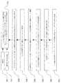
図1に、本発明の対話画像システムの一実施形態の概略図が示されている。対話画像システムは、ホスト10と、基準点12及び14と、対話装置20と、画像表示装置80とを有する。ホスト10は、例えばゲームホスト又はコンピュータシステムのホストとすることができ、第一の無線モジュール16及びアクセス装置18を有する。アクセス装置18は、例えばディスク90、フラッシュメモリドライブ又は記憶装置内のソフトウェアをアクセスために用いられ、使用者がソフトウェアを操作できるようにソフトウェアの状態が画像表示装置80に表示される。画像表示装置80のスクリーン801に、例えば光線銃の照準点又はソフトウェアの制御カーソル等のカーソル802を表示することができる。基準点12及び14は、例えば複数の赤外線発光ダイオード(波長は例えば940nmである)、レーザダイオード又は紫外線などの特定の波長の光源を配列させて形成されたさまざまな形状を持つ基準点とすることができ、画像表示装置80又はホスト10に対して電気的に接続し、又は独立した電源により発光するように消費電力を提供する。また、基準点の数は二個に限定されず、一つ又は複数個とすることができる。対話装置20は、基準点12及び14を撮像し、対話装置20と基準点12及び14との間の相対位置及び/又は角度変化を判定し、スクリーン801にあるカーソル802の動きを相対的に制御する。対話装置20は、ホスト10が実行しているソフトウェア(例えば、ゲームソフトウェア又はコンピュータソフトウェアなど)を制御するために用いられる。ホスト10が実行しているソフトウェアがゲームソフトウェアである場合、対話装置20は例えば光線銃、ビリヤードスティック、ゴルフクラブ、テニスラケット、野球バット、バドミントンラケット、卓球ラケットなどとしてゲームの進行について所望の操作をすることができる。また、ホスト10が実行しているソフトウェアがコンピュータソフトウェアである場合、対話装置20は例えばポインタ(カーソル)位置決め装置として該コンピュータソフトウェアの実行を制御することができる。 FIG. 1 shows a schematic diagram of an embodiment of the interactive image system of the present invention. The interactive image system includes a
次に図1、2及び3を参照する。図2は本発明の対話装置20の一実施形態を示すブロック図である。対話装置20は、画像モジュール21と、処理部22と、変調モジュール23と、動き検出モジュール24と、第二の無線モジュール25とを有する。画像モジュール21は、光フィルタモジュール210と、画像検出モジュール212と、画像処理モジュール214とを備える。光フィルタモジュール210は、所定の帯域(例えば赤外線又は紫外線などの所定の波長範囲の帯域)以外の帯域の光を遮断し、これは画像検出モジュール212に基準点12及び14からの光のみを受光させ、他の光源による干渉を排除するためである。画像検出モジュール212はセンサアレイ(図示せず)を有し、その視野角の範囲及び基準点12及び14の照射角度により、検出可能範囲“A”が決められ(図1参照)、また所定のサンプリング周波数(例えば60〜200フレーム/秒)で基準点12及び14からの光を検出し、デジタル画像を形成する。図1には、検出可能範囲“A”の一例を示したが、実際的に該検出可能範囲“A”をさらに広くしても構わない。画像検出モジュール212について検出可能範囲“A”内に照準を向けると、画像モジュール21が光フィルタモジュール210を有するため、デジタル画像は基準点12及び14のイメージのみを含むことになる。画像検出モジュール212は、例えばCCD(電荷結合素子)イメージセンサ又はCMOS(相補型金属酸化膜半導体)イメージセンサとすることができる。画像処理モジュール214は、画像検出モジュール212からの複数のデジタル画像により、デジタル画像の間での基準点12及び14のイメージの動きベクトルを算出して処理部22に出力する。画像検出モジュール212が出力したデジタル画像は処理部22により処理することができ、複数のデジタル画像の間での基準点12及び14にかかるイメージの動きベクトルを算出する。 Reference is now made to FIGS. FIG. 2 is a block diagram showing an embodiment of the
動き検出モジュール24は、例えば加速度センサ又はジャイロセンサとすることができ、対話装置20の二次元又は三次元の加速度変化を検出するために用いられ、電位差信号又は電流信号を出力する。例えば、対話装置20がゲームの野球バットとして機能する場合、動き検出モジュール24が使用者(図示せず)の打撃の状態を検出でき、電気信号(電位差信号又は電流信号)を生成する。処理部22は該電気信号に従って対話装置20の加速度を算出し、第二の無線モジュール25を制御して該加速度をホスト10の第一の無線モジュール16に対して送信させ、ソフトウェアの実行を相対的に制御する。 The
変調モジュール23は、所定の条件に従って画像モジュール21のサンプリング周波数を変調する。例えば一実施形態において、変調モジュール23は、図3の示す如く、マルチプレクサ26を介してサンプリング周波数を変調する。また、画像モジュール21がデジタル画像の間での基準点12及び14のイメージの動きベクトルを計算できるために、サンプリング周波数波は60フレーム/秒(fps)より高いことが好ましく、かつハードウェアの伝送速度に基づき、サンプリング周波数は200フレーム/秒に達することができる。変調モジュール23については必ずしも処理部22内に設置されるとは限らない、図2に示されたものは単なる一実施形態である。本発明において、画像モジュール21のサンプリング周波数を変調するために用いられる所定の条件は以下の通りである。(1)ホスト10から対話装置20に送信され、ホスト10のアクセス装置18がアクセスしているソフトウェアにより決定される周波数選択信号であり、例えばダイナミックなゲームの場合にサンプリング周波数が高く設定され、静的なゲームの場合にサンプリング周波数が低く設定され、又は使用者により所望のサンプリング周波数に設定される。(2)対話装置20が算出したデジタル画像の間での基準点12及び14のイメージの動きベクトルである。(3)処理部22が計算した対話装置20の加速度である。処理部22は、前記所定の条件の一つ又は複数の組み合わせにより(図3参照)、変調モジュール23を制御して画像モジュール21のサンプリング周波数をリアルタイムで直ちに変調を行う。これにより、ホスト10が実行しているソフトウェアは画像モジュール21によって高速度で撮像する必要がない場合、サンプリング周波数を低減することで対話装置20の全消費電力を低減できる。 The
次に図1及び4を参照する。図4は本発明の対話装置の運転制御方法の一実施形態を示すフローチャートであり、所定のサンプリング周波数で基準点を撮像して第一の画像及び第二の画像を生成し、かつ該第一の画像と第二の画像との間での前記基準点のイメージの動きベクトルを計算して出力する画像モジュールを提供するステップ(ステップB1)と、ホストと通信するための無線モジュールを提供するステップ(ステップB2)と、対話装置の状態を検出して電気信号を生成する動き検出モジュールを提供するステップ(ステップB3)と、前記電気信号に応じて対話装置の加速度を計算し、前記無線モジュールを制御して前記動きベクトル及び加速度をホストに対して送信させ、かつ所定の条件に従って前記画像モジュールのサンプリング周波数をリアルタイムで直ちに変調する処理部を提供するステップ(ステップB4)とを備える。先ず、画像モジュール21の画像検出モジュール212が光フィルタモジュール210を介して基準点12及び14の光を検出して複数のデジタル画像を形成する。画像処理モジュール214がデジタル画像により、デジタル画像の間での基準点12及び14のイメージの動きベクトルを算出し、その計算方法は後述する段落にて説明される(ステップB1)。動き検出モジュール24は、使用者が操作する対話装置20の状態を検出し、電位差信号又は電流信号を生成する(ステップB3)。次に、処理部22が電気信号に応じて対話装置20の加速度を計算し、第二の無線モジュール25を制御して該加速度及び動きベクトルの信号をホスト10に対して送信させ、相対制御を行い、かつ前記所定の条件の一つ又は複数の組み合わせにより変調モジュール23を制御して画像モジュール21のサンプリング周波数をリアルタイムで直ちに変調する(ステップB4)。 Reference is now made to FIGS. FIG. 4 is a flowchart showing an embodiment of the operation control method of the interactive apparatus according to the present invention. The reference point is imaged at a predetermined sampling frequency to generate the first image and the second image, and the first image is generated. Providing an image module for calculating and outputting a motion vector of the reference point image between the first image and the second image (step B1), and providing a wireless module for communicating with the host (Step B2), a step (Step B3) of providing a motion detection module that detects the state of the interactive device and generates an electrical signal, calculates an acceleration of the interactive device according to the electrical signal, and Control to transmit the motion vector and acceleration to the host, and in real time the sampling frequency of the image module according to a predetermined condition Providing a processing unit for immediate modulation (step B4). First, the
本発明をさらに説明するために、対話装置20が画像表示装置80上のカーソル802の動きベクトルを計算する一実施形態の例を挙げるが、本発明を限定するものではない。 In order to further explain the present invention, an example of an embodiment in which the
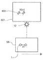
図5〜8に示すように、この実施形態において、対話装置20は、画像表示装置80のスクリーン801上に示すカーソル802の動きを制御することに用いられる。カーソル802は、光線銃の照準点又はソフトウェアの制御カーソルとすることができる。基準点12及び14は異なる面積とされ、かつ同じ形状の二つの基準点とする。例えば、基準点12は大きい星の符号で表示され、デジタル画像DIにてI12を呈する。基準点14は小さい星の符号で表示され、デジタル画像DIにてI14を呈する。カーソル802の制御方法は、所定の帯域の光を生成し、かつ所定の範囲を定義する二つの基準点を提供するステップ150と、画像モジュールについて前記所定の範囲内にて照準を向けるステップ250と、前記画像モジュールにより前記所定の帯域の光を受光し、デジタル画像を生成するステップ300と、前記デジタル画像にある前記基準点のイメージの位置及び形状を判断し、第一のパラメータを生成するステップ400と、前記第一のパラメータについて距離補正及び角度補正を行うステップ500と、前記画像モジュールの照準位置を前記所定の範囲内に移動させ、第二のパラメータを生成するステップ600と、前記補正された第一のパラメータ及び第二のパラメータにて、前記デジタル画像の間の前記基準点のイメージの移動距離を算出することによりカーソルの動きを制御するステップ700とを備える。該ステップ700において、前記第二のパラメータに距離補正及び角度補正を行うステップ710及び前記カーソル802の動き感度を制御するための比例係数を入力するステップ720とを同時に行う。なお、ステップ720は、異なるアプリケーションに応じて省略してもよい。As shown in FIGS. 5 to 8, in this embodiment, the
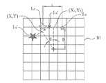
図1、5及び6aを参照すると、対話装置20には工場から出荷される前に、その画像処理モジュール214に予め所定位置パラメータ及び所定距離パラメータが設定されていることが好ましい。それらのパラメータは、対話装置20が基準点12及び14から所定の距離(例えば3メートル)をもって離れ、かつ画像検出モジュール212を介して検出された基準点12及び14のイメージI12及びI14に基づき算出された所定のパラメータであり、図6aに示すように、距離補正及び角度補正の基準とする。所定位置パラメータ及び所定距離パラメータは、例えばセンサアレイの中心点“+”を原点とする平面的な座標空間(以下、「平面座標空間」という)などのように、画像検出モジュール212のセンサアレイにより形成された平面座標空間に応じて定義することができる。例えば、所定位置パラメータは、その平面座標空間における基準点12及び14の所定のイメージI12及びI14の座標と、平均座標(X0、Y0)と、所定のイメージI12及びI14を連結する線分の傾き角度とを含む。所定距離パラメータは、その平面座標空間での基準点12及び14の所定のイメージI12とI14との間の距離L、及び所定のイメージI12、I14の平均座標(X0、Y0)と中心点“+”との間の距離Dとを含む。Referring to FIGS. 1, 5 and 6a, it is preferable that a predetermined position parameter and a predetermined distance parameter are set in advance in the
先ず、基準点12及び14は、例えば赤外線信号等の所定の帯域の光を生成する。画像検出モジュール212の視野角範囲及び基準点12、14の照射角度により、基準点12及び14の周りに検出可能範囲“A”を決定できる(ステップ150)。次に、対話装置20の画像検出モジュール212について検出可能範囲“A”内に照準を向ける(ステップ250)。本発明に使用される画像検出モジュール212が所定の帯域の光のみを検出できるため、図6aに示したように、基準点12及び14のイメージI12’、I14’のみを含むデジタル画像DIを形成する(ステップ300)。また、対話装置20を使い前記デジタル画像を検出する際に、対話装置20が時計回り方向に沿ってθの角度で回転すると、このときの基準点のイメージI12'及びI14'と、画像検出モジュール212が前述した所定の距離で検出した所定のイメージI12及びI14との間にθの角度の差を生じるため、画像検出モジュール212で同じ位置に照準を向けて撮像したとしても、基準点のイメージI12'及びI14'の平均座標(X、Y)は、所定の基準点のイメージI12、I14の平均座標(X0、Y0)と一致しない。First, the
図1、5、6a及び6bに示すように、画像処理モジュール214は基準点のイメージI12'及びI14'の位置及び形状を判断し、第一の位置パラメータと、第一の距離パラメータと、第一の形状パラメータとを含む第一のパラメータを生成する(ステップ400)。画像処理モジュール214は、第一の位置パラメータ(例えば基準点のイメージI12'及びI14'の平均座標及びそれらイメージを連結した線分の傾き角度を含む)と所定位置パラメータ(例えば所定の基準点のイメージI12、I14及びそれらを連結した線分の傾き角度を含む)との間の角度の差θに基づき、角度補正を行う(ステップ500)。この角度補正は式(1)により行われる。
ここで、角度θは、第一の位置パラメータと所定位置パラメータとの間の回転角度の差であり、X及びYは、補正前における第一の位置パラメータの平均座標であり、X'及びY'(図示せず)は、補正後における基準点のイメージの位置の平均座標である。これによって、補正された基準点12及び14のイメージは、同じ基準に基づき得られたものになる。このように、画像検出モジュール212は、画像表示装置80から同じ距離で撮像すれば、いかなる回転角度で撮像しても同じイメージを検出できる。 Here, the angle θ is a difference in rotation angle between the first position parameter and the predetermined position parameter, X and Y are average coordinates of the first position parameter before correction, and X ′ and Y '(Not shown) is an average coordinate of the position of the image of the reference point after correction. Thereby, the corrected images of the
しかしながら、前記角度の差θが180度より大きく、図6bに示す基準点のイメージI12''及びI14''を形成する場合において、もし基準点のイメージI12及びI14の間に差異がない(基準点12及び14が同じ大きさ及び形状を持つ)とすると、基準点のイメージI12''及びI14''が基準点のイメージI12'及びI14'(図6a)を回転させて形成されたのか、又はこれらのイメージを移動させて形成されたのかを判断できなくなる。したがって、ここで異なる面積の二つの基準点12及び14を使い、画像処理モジュール214が得られたイメージの形状パラメータ(例えば基準点のイメージの面積)に基づき、先に基準点12及び14のイメージの各位置を判断した後、角度補正を行う。これによって、画像検出モジュール212を操作するときの回転角度が180度を超えたとしても、正確な角度補正が行われる。However, if the angle difference θ is greater than 180 degrees to form the reference point images I12 ″ and I14 ″ shown in FIG. 6b, the difference between the reference point images I12 and I14 is different. (Reference points 12 and 14 have the same size and shape), the reference point images I12 ″ and I14 ″ represent the reference point images I12 ′ and I14 ′ (FIG. 6a). It is impossible to determine whether the image is formed by rotating or by moving these images. Accordingly, the two
図7に示すように、本発明の実施形態に係る距離補正の方法が開示されている。対話装置20の画像検出モジュール212を使い所定の距離で撮像すると、基準点12及び14の所定のイメージI12及びI14が得られる。対話装置20と基準点12及び14との間の距離が大きくなると、図中に示したI12'''、I14'''のように、撮像されたイメージが小さくなり、かつ基準点のイメージの平均座標がセンサアレイの中心点“+”に近くなる。しかし、このような動作による位置の変化は、使用者が対話装置20の照準位置を移動させることを表してはいない。その位置の変化を補正しないと、撮像距離の変化が対話装置20の照準位置の移動によるものであると誤認識される可能性がある。ここで、イメージの距離パラメータにおいて、イメージI12とI14との間の距離をLとし、それらの平均座標(X0,Y0)とセンサアレイの中心点“+”との間の距離をDとする。第一の距離パラメータについては、イメージI12'''とI14'''との間の距離をlとし、それらの平均座標とセンサアレイの中心点“+”との間の距離をdとする。これによって、式(2)の比例関係により、異なる撮像距離によりなされる位置の差を補正する(ステップ500)。
図8に示すように、基準点のイメージの位置が補正された後には、イメージi12及びi14になる。それらは同じ所定の距離及び回転角度に基づき得られたイメージであり、その平均座標は(Xi,Yi)になる。そして、検出可能範囲“A”内で対話装置20の照準位置を移動させ、基準点のイメージi12'、i14'を含む第二の画像が得られる(ステップ600)。このとき、画像検出モジュール212は検出された第二の画像を画像処理モジュール214に送信する。画像処理モジュール214はその第二の画像に基づき、第二のパラメータを生成する。第二のパラメータは、画像検出モジュール212の照準位置が移動された後における第二の画像上の基準点12及び14の第二の位置パラメータ及び第二の距離パラメータを含む。第二の位置パラメータは、例えばセンサアレイの中心点“+”を原点とする平面座標空間などのように、画像検出モジュール212のセンサアレイにより形成された平面座標空間に応じた移動後の基準点12及び14のイメージの平均座標を含む。第二の距離パラメータは、上記と同じ平面座標空間に応じた移動後における基準点12及び14のイメージの間の距離を含む。画像処理モジュール214は、補正された第一の位置パラメータ及び第二の位置パラメータにより、基準点のイメージi12及びi14からイメージi12'、i14'までの動きベクトルΔSを算出する。それと同時に、上述した角度及び距離の補正方法により、第二のパラメータに回転角度及び距離の偏差を補正し(ステップ710)、正確なカーソル制御を行う。なお、第二のパラメータに行われる補正方法は第一のパラメータに行われる補正方法と類似するため、その詳しい説明を省略する。次に、処理部22は前記第二の無線モジュール25を制御して前記動きベクトルΔSを画像表示装置80に対して無線伝送する。画像表示装置80には、好適に、応用ソフトウェアがインストールされており、使用者インターフェース及びカーソル802の制御に用いられ、第二の無線モジュール25からの動きベクトルの信号を受信した後、これに従ってスクリーン801のカーソル802の動きを制御する(ステップ700)。また、基準点のイメージi12及びi14の動きベクトルΔSを計算するときに、比例係数(スケール因子)Xscale及びYscaleを入力でき(ステップ720)、スクリーン801上でのカーソル802の動き感度を制御する。例えば、動きベクトルΔSは式(3)のように計算できる。
ここで、ΔSXは動きベクトルの水平成分であり、ΔSYは動きベクトルの垂直成分である。式(3)により、Xscale及びYscaleの値が大きくなると、カーソル802の動き感度が小さくなり、すなわち、カーソル802をスクリーン801上にて同じ距離で移動させるために、対話装置20の照準位置の移動距離をより大きくする必要がある。逆に、式(3)において、Xscale及びYscaleの値が小さくなると、カーソル802の動き感度が大きくなり、すなわち、対話装置20の照準位置の移動距離を大きく移動させることを要さずに、スクリーン801上にてカーソル802を同じ距離で移動することができ、本発明の対話装置20の実用性を高める。Here, ΔSX is a horizontal component of the motion vector, and ΔSY is a vertical component of the motion vector. According to the equation (3), when the values of Xscale and Yscale are increased, the motion sensitivity of the
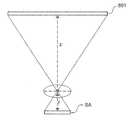
図9〜11を参照し、以下では、処理部22が対話装置20の画像処理モジュール214にて得られたデジタル画像の間での基準点のイメージの動きベクトルにより変調モジュール23を制御して画像モジュール21のサンプリング周波数を変調させることについて、一例を挙げて説明する。図9は、画像検出モジュール212の像距離fと、画像検出モジュール212及びスクリーン801の間の距離Fとの比例関係を示す。一実施形態において、像距離fを32mmとし、画像検出モジュール212とスクリーン801との間の距離Fを1.6メートルとし、すなわち、F/f=50である。図10と併せて参照すれば、画像表示装置80のスクリーン801にあるカーソル802の移動距離は画像検出モジュール212のセンサアレSAにある基準点のイメージI12の50倍であることが明らかである。すなわち、画像処理モジュール214が1μmの動きベクトルを算出した場合、カーソル802が画像表示装置80のスクリーン801に50μmを移動していることを意味する。9 to 11, in the following, the
続いて画像モジュール21のサンプリング周波数の閾値を設定する一例を説明する。画像検出モジュール212のセンサアレイSAの画素ごとのサイズを15μm×15μmとし、サンプリング周波数を200フレーム/秒として二つのフレームの間の基準点12の動きベクトルの大きさを画素二つ分とした場合、画像表示装置80のスクリーン801上でのカーソル802の1秒ごとの位置変化は(15×10−3/25.4)×2×50×200=11.81インチ/秒と求められる。同様に、サンプリング周波数を100フレーム/秒、50フレーム/秒とした場合、カーソル802の1秒ごとの位置変化はそれぞれ5.91インチ/秒、2.95インチ/秒と求められる。図11を参照すると、画像モジュール21のサンプリング周波数と、画像表示装置80のスクリーン801上におけるカーソル802の位置変化との関係図が示され、本実施形態では、サンプリング周波数の閾値が2.95インチ/秒及び5.91インチ/秒に設定される。すなわち、スクリーン801上でのカーソル802の位置変化が2.95インチ/秒より小さい場合、変調モジュール23は画像モジュール21のサンプリング周波数を変調して50フレーム/秒のサンプリング周波数で撮像させる。また、その位置変化が5.91インチ/秒より小さく、かつ2.95インチ/秒より大きい場合、画像モジュール21は100フレーム/秒のサンプリング周波数で撮像する。また、その位置変化が5.91インチ/秒より大きい場合、画像モジュール21は200フレーム/秒のサンプリング周波数で撮像する。Next, an example of setting the threshold value of the sampling frequency of the
図9〜11に示した比例値、閾値、閾値の数及びサンプリング周波数値は単なる一実施例として示したものに過ぎず、本発明を限定するするものではなく、比例値、閾値、閾値の数及びサンプリング周波数値は実際の製品に応じて設定できる。また、処理部22が対話装置20の動き検出モジュール24で得られた加速度により変調モジュール23を制御して画像モジュール21のサンプリング周波数の変調を行う方法については、動き検出モジュール24から出力された電気信号を一つ又は複数の閾値と比較し、処理部22がその比較の結果に基づいて変調モジュール23を制御して画像モジュール21のサンプリング周波数を変調させることである。これにより、カーソル802の位置変化及び/又は対話装置20の加速度が小さい場合、変調モジュール23が画像モジュール21のサンプリング周波数を変調し、画像モジュール21をより低いサンプリング周波数で撮像させ、対話装置20の消費電力を有効に低減できる。 The proportional values, threshold values, the number of threshold values, and the sampling frequency values shown in FIGS. 9 to 11 are merely examples, and are not intended to limit the present invention. The sampling frequency value can be set according to the actual product. In addition, regarding a method in which the
また、対話画像システムの付近に、例えばハロゲンランプ又は太陽光源などの他の光源があり、かつ該光源から生成された光の帯域の一部又は全部が基準点12及び14からの光の帯域と重なった場合、周期的又は非周期的な信号で基準点12及び14からの光を変調することができる。一実施形態において、変調ユニット(図示せず)が基準点12及び14の消費電力を提供する装置に設けられ、例えばホスト10又は画像表示装置80に設けられる。そして、画像モジュール21のサンプリング周波数は変調ユニットの変調周波数の倍数であることが好ましい。これにより、画像の撮像と基準点12及び14の点灯を同調させることができる。例えば一実施形態において、画像モジュール21のサンプリング周波数を200Hzとし(5msecおきにサンプリングする)、基準点12及び14の変調周波数を20Hzとする(50msecおきに点灯させる)。すなわち、画像モジュール21が十回目のサンプリングを行うとき、基準点12及び14が点灯し、画像モジュール21は基準点12及び14から生成された光を撮像することができる。また、対話装置20には変調された光を認識するための復調装置が設けられ、他の光源からの画像認識に対する影響(干渉)を排除できるようにする。 In addition, there is another light source such as a halogen lamp or a solar light source in the vicinity of the interactive image system, and a part or all of the light band generated from the light source is the light band from the
上記のように、従来のリモート装置(コントローラ)においては、イメージセンサのサンプリング周波数が固定されているため、消費電力が比較的に高く、電池モジュールを頻繁に充電必要のためにその更新に要する時間が短くなってしまうという問題がある。本発明のゲームシステム、ゲーム用装置及びその運転制御方法によれば、画像モジュールのサンプリング周波数をリアルタイムで直ちに変調することにより、対話装置の消費電力を低減でき、その実用性を向上させることができる。 As described above, in the conventional remote device (controller), since the sampling frequency of the image sensor is fixed, the power consumption is relatively high, and the battery module needs to be charged frequently, so the time required to update it There is a problem that becomes short. According to the game system, the game device, and the driving control method thereof of the present invention, the power consumption of the interactive device can be reduced and its practicality can be improved by immediately modulating the sampling frequency of the image module in real time. .
なお、本発明を上記の好ましい実施形態に関して記載したが、本発明はこれらの実施形態に限定されるものではない。当業者は、特許を請求する本発明の範囲及び趣旨から逸脱することなく、種々の変形及び変更が可能である。 In addition, although this invention was described regarding said preferable embodiment, this invention is not limited to these embodiment. Those skilled in the art will recognize that various modifications and changes can be made without departing from the scope and spirit of the invention as claimed.
10 ホスト
12、14 基準点
16 第一の無線モジュール
18 アクセス装置
20 対話装置
21 画像モジュール
210 光フィルタモジュール
212 画像検出モジュール
214 画像処理モジュール
22 処理部
23 変調モジュール
24 動き検出モジュール
25 第二の無線モジュール
26 マルチプレクサ
80 画像表示装置
801 スクリーン
802 カーソル
90 ディスク
L,l 基準点のイメージの間の距離
θ 回転角度
ΔS 動きベクトル
ΔSX 動きベクトルの水平成分
ΔSY 動きベクトルの垂直成分
SA センサアレイ
A 検出可能範囲
DI デジタル画像
B1〜B4 ステップ
150〜720 ステップ
f 画像検出モジュールの像距離
Xscale、Yscale 比例係数
F 画像検出モジュールとスクリーンとの間の距離
D、d 基準点のイメージの平均座標とセンサアレイの中心との間の距離
i12、i14、i12'、i14' 基準点のイメージ
I12、I14、I12'、I14'、I12''、I14''、I12'''、I14''' 基準点のイメージ
(X、Y)、(X0、Y0)、(Xi、Yi) 基準点のイメージの平均座標DESCRIPTION OF
Claims (29)
Translated fromJapanese所定の帯域の光を生成する少なくとも一つの基準点と、
対話装置とを備える対話画像システムであって、前記対話装置は、
前記第一の無線モジュールと通信するための第二の無線モジュールと、
所定のサンプリング周波数で前記基準点を撮像して第一の画像及び第二の画像を生成し、かつ該第一の画像と第二の画像との間での前記基準点のイメージの動きベクトルを計算して出力する画像モジュールと、
前記画像モジュールのサンプリング周波数を変調するための変調モジュールと、
前記第二の無線モジュールを制御して前記動きベクトルを前記第一の無線モジュールに対して送信させ、かつ所定の条件に従って前記変調モジュールを制御して前記画像モジュールのサンプリング周波数を直ちに変調させる処理部とを備える対話画像システム。A host comprising a first wireless module and an access device for accessing software;
At least one reference point for generating light in a predetermined band;
An interactive image system comprising an interactive device, wherein the interactive device
A second wireless module for communicating with the first wireless module;
The reference point is imaged at a predetermined sampling frequency to generate a first image and a second image, and a motion vector of the image of the reference point between the first image and the second image is obtained. An image module to calculate and output;
A modulation module for modulating the sampling frequency of the image module;
A processing unit that controls the second wireless module to transmit the motion vector to the first wireless module, and controls the modulation module according to a predetermined condition to immediately modulate the sampling frequency of the image module. An interactive image system comprising:
前記画像モジュールは、
前記所定の帯域以外の帯域の光を遮断するための赤外線フィルタと、
所定のサンプリング周波数で前記基準点を撮像し、前記第一の画像及び第二の画像を生成する画像検出モジュールと、
前記第一の画像と前記第二の画像との間での前記基準点のイメージの動きベクトルを計算して出力する画像処理モジュールとをさらに備えることを特徴とする請求項1に記載の対話画像システム。An interactive image system having an infrared diode at the reference point, wherein the predetermined band is an infrared band;
The image module includes:
An infrared filter for blocking light in a band other than the predetermined band;
An image detection module that images the reference point at a predetermined sampling frequency and generates the first image and the second image;
The interactive image according to claim 1, further comprising an image processing module that calculates and outputs a motion vector of the image of the reference point between the first image and the second image. system.
前記ホストと通信するための無線モジュールと、
所定のサンプリング周波数で前記基準点を撮像して第一の画像及び第二の画像を生成し、かつ該第一の画像と第二の画像との間での前記基準点のイメージの動きベクトルを計算して出力する画像モジュールと、
前記画像モジュールのサンプリング周波数を変調するための変調モジュールと、
前記無線モジュールを制御して前記動きベクトルを前記ホストに対して送信させ、かつ所定の条件に従って前記変調モジュールを制御して前記画像モジュールのサンプリング周波数を直ちに変調させる処理部と、を備える対話装置。An interactive apparatus for use in an interactive image system, comprising: an interactive apparatus; a host that wirelessly communicates with the interactive apparatus; and at least one reference point that generates light of a predetermined band.
A wireless module for communicating with the host;
The reference point is imaged at a predetermined sampling frequency to generate a first image and a second image, and a motion vector of the image of the reference point between the first image and the second image is obtained. An image module to calculate and output;
A modulation module for modulating the sampling frequency of the image module;
And a processing unit that controls the wireless module to transmit the motion vector to the host and controls the modulation module according to a predetermined condition to immediately modulate the sampling frequency of the image module.
前記所定の帯域以外の帯域の光を遮断するための赤外線フィルタと、
所定のサンプリング周波数で前記基準点を撮像して前記第一の画像及び第二の画像を生成する画像検出モジュールと、
前記第一の画像と前記第二の画像との間での前記基準点のイメージの動きベクトルを計算して出力する画像処理モジュールとをさらに備えることを特徴とする請求項15に記載の対話装置。The predetermined band is an infrared band, and the image module is
An infrared filter for blocking light in a band other than the predetermined band;
An image detection module that images the reference point at a predetermined sampling frequency to generate the first image and the second image;
The interactive apparatus according to claim 15, further comprising: an image processing module that calculates and outputs a motion vector of the image of the reference point between the first image and the second image. .
所定のサンプリング周波数で前記基準点を撮像して第一の画像及び第二の画像を生成し、かつ該第一の画像と第二の画像との間での前記基準点のイメージの動きベクトルを計算して出力する画像モジュールを提供するステップと、
前記ホストと通信するための無線モジュールを提供するステップと、
前記無線モジュールを制御して前記動きベクトルを前記ホストに対して送信させ、かつ所定の条件に従って前記画像モジュールのサンプリング周波数を直ちに変調する処理部を提供するステップと、を備える対話装置の運転制御方法。An operation control method for an interactive apparatus used in an interactive image system, comprising: an interactive apparatus; a host wirelessly communicating with the interactive apparatus; and at least one reference point that generates light of a predetermined band.
The reference point is imaged at a predetermined sampling frequency to generate a first image and a second image, and a motion vector of the image of the reference point between the first image and the second image is obtained. Providing an image module for calculating and outputting;
Providing a wireless module for communicating with the host;
Providing a processing unit that controls the wireless module to transmit the motion vector to the host and immediately modulates a sampling frequency of the image module according to a predetermined condition. .
前記電気信号に応じて前記対話装置の加速度を計算するステップと、
前記無線モジュールにより前記加速度を前記ホストに送信するステップとをさらに備えることを特徴とする請求項24に記載の対話装置の運転制御方法。Providing a motion detection module for detecting a state of the interactive device and generating an electrical signal;
Calculating the acceleration of the interactive device in response to the electrical signal;
25. The operation control method for an interactive apparatus according to claim 24, further comprising: transmitting the acceleration to the host by the wireless module.
所定の帯域の光を生成する少なくとも一つの基準点と、
対話装置とを備える対話画像システムであって、前記対話装置は、
前記第一の無線モジュールと通信するための第二の無線モジュールと、
所定のサンプリング周波数で前記基準点を撮像して第一の画像及び第二の画像を生成する画像モジュールと、
前記画像モジュールのサンプリング周波数を変調するための変調モジュールと、
前記第一の画像と前記第二の画像との間での前記基準点のイメージの動きベクトルを計算し、前記第二の無線モジュールを制御して前記動きベクトルを前記第一の無線モジュールに対して送信させ、かつ所定の条件に従って前記変調モジュールを制御して前記画像モジュールのサンプリング周波数を直ちに変調させる処理部とを備える対話画像システム。A host comprising a first wireless module and an access device for accessing software;
At least one reference point for generating light in a predetermined band;
An interactive image system comprising an interactive device, wherein the interactive device
A second wireless module for communicating with the first wireless module;
An image module that images the reference point at a predetermined sampling frequency to generate a first image and a second image;
A modulation module for modulating the sampling frequency of the image module;
Calculating a motion vector of the image of the reference point between the first image and the second image, and controlling the second wireless module to send the motion vector to the first wireless module; And a processing unit that controls the modulation module according to a predetermined condition to immediately modulate the sampling frequency of the image module.
Applications Claiming Priority (2)
| Application Number | Priority Date | Filing Date | Title |
|---|---|---|---|
| TW096131177ATWI338241B (en) | 2007-08-23 | 2007-08-23 | Interactive image system, interactive device and operative method thereof |
| TW096131177 | 2007-08-23 |
Publications (2)
| Publication Number | Publication Date |
|---|---|
| JP2009050701Atrue JP2009050701A (en) | 2009-03-12 |
| JP5049228B2 JP5049228B2 (en) | 2012-10-17 |
Family
ID=40280341
Family Applications (1)
| Application Number | Title | Priority Date | Filing Date |
|---|---|---|---|
| JP2008212786AExpired - Fee RelatedJP5049228B2 (en) | 2007-08-23 | 2008-08-21 | Dialogue image system, dialogue apparatus and operation control method thereof |
Country Status (4)
| Country | Link |
|---|---|
| US (1) | US8553094B2 (en) |
| JP (1) | JP5049228B2 (en) |
| DE (1) | DE102008024462B4 (en) |
| TW (1) | TWI338241B (en) |
Families Citing this family (21)
| Publication number | Priority date | Publication date | Assignee | Title |
|---|---|---|---|---|
| US6990639B2 (en) | 2002-02-07 | 2006-01-24 | Microsoft Corporation | System and process for controlling electronic components in a ubiquitous computing environment using multimodal integration |
| US7665041B2 (en) | 2003-03-25 | 2010-02-16 | Microsoft Corporation | Architecture for controlling a computer using hand gestures |
| US8745541B2 (en)* | 2003-03-25 | 2014-06-03 | Microsoft Corporation | Architecture for controlling a computer using hand gestures |
| KR20100087920A (en)* | 2009-01-29 | 2010-08-06 | 삼성전자주식회사 | Method and apparatus for obtaining image data |
| TWI507925B (en)* | 2010-06-23 | 2015-11-11 | Pixart Imaging Inc | You can switch the range of interactive pointing devices and how to switch fetch ranges |
| TWI446218B (en)* | 2010-06-30 | 2014-07-21 | Pixart Imaging Inc | A method of switching the range of interactive pointing devices and a handover fetch for interactive pointing devices |
| CN102375532B (en)* | 2010-08-10 | 2014-01-22 | 原相科技股份有限公司 | Interactive pointing device and capturing range switching method |
| TWI492096B (en) | 2010-10-29 | 2015-07-11 | Au Optronics Corp | 3d image interactive system and position-bias compensation method of the same |
| TWI486822B (en)* | 2011-02-16 | 2015-06-01 | Pixart Imaging Inc | Image retrieving apparatus for optical pointing apparatus |
| US9179182B2 (en) | 2011-04-12 | 2015-11-03 | Kenneth J. Huebner | Interactive multi-display control systems |
| TWI441042B (en)* | 2011-07-01 | 2014-06-11 | Pixart Imaging Inc | Interactive image system, interactive control device and operation method thereof |
| CN102955577A (en)* | 2011-08-26 | 2013-03-06 | 奇高电子股份有限公司 | Optical pointer control system and method |
| CN102968896B (en)* | 2011-08-29 | 2015-07-22 | 奇高电子股份有限公司 | Optical remote control system and light source control method used therein |
| US20130082923A1 (en)* | 2011-10-03 | 2013-04-04 | Chip Goal Electronics Corporation, R.O.C. | Optical pointer control system and method therefor |
| US8811938B2 (en) | 2011-12-16 | 2014-08-19 | Microsoft Corporation | Providing a user interface experience based on inferred vehicle state |
| US9304574B2 (en) | 2012-04-13 | 2016-04-05 | Pixart Imaging Inc. | Remote device and power saving method of interactive system |
| CN102671397B (en)* | 2012-04-16 | 2013-11-13 | 宁波新文三维股份有限公司 | Seven-dimensional cinema and interaction method thereof |
| TWI468997B (en)* | 2013-01-09 | 2015-01-11 | Pixart Imaging Inc | Pointing system and image system having improved operable range |
| US9804689B2 (en) | 2013-02-19 | 2017-10-31 | Pixart Imaging Inc. | Handheld pointer device and pointer positioning method thereof |
| CN110058690B (en)* | 2019-04-10 | 2022-12-30 | 南京熊大巨幕智能科技有限公司 | Interactive display device, method, apparatus and computer-readable storage medium |
| TWI756728B (en)* | 2020-07-01 | 2022-03-01 | 立積電子股份有限公司 | Object recognition method and object recognition device |
Citations (8)
| Publication number | Priority date | Publication date | Assignee | Title |
|---|---|---|---|---|
| JPH0871252A (en)* | 1994-09-05 | 1996-03-19 | Taito Corp | Method and device for detecting relative position between video screen and gun on firing game device |
| JP2000267799A (en)* | 1999-03-19 | 2000-09-29 | Mitsubishi Electric Corp | Coordinate position control system, coordinate position control method, and computer-readable recording medium storing a program for causing a computer to execute the method |
| JP2001175872A (en)* | 1999-12-15 | 2001-06-29 | Clarion Co Ltd | Device and method for image processing and recording medium with recorded software for image processing |
| JP2002081909A (en)* | 2000-09-11 | 2002-03-22 | Sony Corp | Device and method for position detection and entertainment device |
| JP2003208263A (en)* | 2002-01-12 | 2003-07-25 | Sega Corp | Image processing apparatus having control device and attachment body thereof |
| JP2005185740A (en)* | 2003-12-26 | 2005-07-14 | Sega Corp | Information processing device, game device, image generation method, and game image generation method |
| JP2007061489A (en)* | 2005-09-01 | 2007-03-15 | Nintendo Co Ltd | Information processing system and program |
| JP2007075213A (en)* | 2005-09-12 | 2007-03-29 | Nintendo Co Ltd | Information processing program |
Family Cites Families (14)
| Publication number | Priority date | Publication date | Assignee | Title |
|---|---|---|---|---|
| US5828406A (en)* | 1994-12-30 | 1998-10-27 | Eastman Kodak Company | Electronic camera having a processor for mapping image pixel signals into color display pixels |
| US6452632B1 (en)* | 1997-01-31 | 2002-09-17 | Kabushiki Kaisha Toshiba | Solid state image sensor and video system using the same |
| US6891570B2 (en)* | 2001-01-31 | 2005-05-10 | Itt Manufacturing Enterprises Inc. | Method and adaptively deriving exposure time and frame rate from image motion |
| ATE447721T1 (en)* | 2001-12-13 | 2009-11-15 | Sirf Tech Inc | QUICK CAPTURE OF A GPS SIGNAL |
| US7394939B2 (en)* | 2003-12-17 | 2008-07-01 | Microsoft Corporation | Managing file stream generation |
| US20050213662A1 (en)* | 2004-03-29 | 2005-09-29 | James Owens | Method of compression and digital imaging device employing compression algorithm |
| JP2006025312A (en)* | 2004-07-09 | 2006-01-26 | Konica Minolta Photo Imaging Inc | Imaging apparatus and image acquisition method |
| KR100703740B1 (en)* | 2004-10-21 | 2007-04-05 | 삼성전자주식회사 | Method and apparatus for efficiently encoding multi-layer based motion vector |
| TWI267754B (en) | 2005-05-18 | 2006-12-01 | Zeroplus Technology Co Ltd | Pointer positioning device of a video camera |
| JP4805633B2 (en)* | 2005-08-22 | 2011-11-02 | 任天堂株式会社 | Game operation device |
| EP1932352A2 (en)* | 2005-09-27 | 2008-06-18 | Koninklijke Philips Electronics N.V. | Motion detection device |
| JP4766320B2 (en)* | 2006-02-06 | 2011-09-07 | カシオ計算機株式会社 | Imaging apparatus and program thereof |
| JP4684147B2 (en)* | 2006-03-28 | 2011-05-18 | 任天堂株式会社 | Inclination calculation device, inclination calculation program, game device, and game program |
| US7515822B2 (en)* | 2006-05-12 | 2009-04-07 | Microsoft Corporation | Imaging systems' direct illumination level adjusting method and system involves adjusting operation of image sensor of imaging system based on detected level of ambient illumination |
- 2007
- 2007-08-23TWTW096131177Apatent/TWI338241B/ennot_activeIP Right Cessation
- 2008
- 2008-03-04USUS12/041,892patent/US8553094B2/enactiveActive
- 2008-05-21DEDE102008024462.7Apatent/DE102008024462B4/ennot_activeExpired - Fee Related
- 2008-08-21JPJP2008212786Apatent/JP5049228B2/ennot_activeExpired - Fee Related
Patent Citations (8)
| Publication number | Priority date | Publication date | Assignee | Title |
|---|---|---|---|---|
| JPH0871252A (en)* | 1994-09-05 | 1996-03-19 | Taito Corp | Method and device for detecting relative position between video screen and gun on firing game device |
| JP2000267799A (en)* | 1999-03-19 | 2000-09-29 | Mitsubishi Electric Corp | Coordinate position control system, coordinate position control method, and computer-readable recording medium storing a program for causing a computer to execute the method |
| JP2001175872A (en)* | 1999-12-15 | 2001-06-29 | Clarion Co Ltd | Device and method for image processing and recording medium with recorded software for image processing |
| JP2002081909A (en)* | 2000-09-11 | 2002-03-22 | Sony Corp | Device and method for position detection and entertainment device |
| JP2003208263A (en)* | 2002-01-12 | 2003-07-25 | Sega Corp | Image processing apparatus having control device and attachment body thereof |
| JP2005185740A (en)* | 2003-12-26 | 2005-07-14 | Sega Corp | Information processing device, game device, image generation method, and game image generation method |
| JP2007061489A (en)* | 2005-09-01 | 2007-03-15 | Nintendo Co Ltd | Information processing system and program |
| JP2007075213A (en)* | 2005-09-12 | 2007-03-29 | Nintendo Co Ltd | Information processing program |
Also Published As
| Publication number | Publication date |
|---|---|
| TW200910146A (en) | 2009-03-01 |
| DE102008024462B4 (en) | 2019-11-14 |
| US20090052730A1 (en) | 2009-02-26 |
| DE102008024462A1 (en) | 2009-02-26 |
| US8553094B2 (en) | 2013-10-08 |
| JP5049228B2 (en) | 2012-10-17 |
| TWI338241B (en) | 2011-03-01 |
Similar Documents
| Publication | Publication Date | Title |
|---|---|---|
| JP5049228B2 (en) | Dialogue image system, dialogue apparatus and operation control method thereof | |
| US11670267B2 (en) | Computer vision and mapping for audio applications | |
| CN112105426B (en) | Power management for optical position tracking devices | |
| US11689877B2 (en) | Immersive augmented reality experiences using spatial audio | |
| KR100714722B1 (en) | Apparatus and method for implementing a pointing user interface using a signal from a light source | |
| US8388146B2 (en) | Anamorphic projection device | |
| US20210042513A1 (en) | Information processing apparatus, information processing method, and program | |
| JP2008269616A (en) | Cursor control device and method for image display, and image system | |
| EP3299937B1 (en) | Information processing device and information processing method | |
| JP2015526927A (en) | Context-driven adjustment of camera parameters | |
| KR102627014B1 (en) | electronic device and method for recognizing gestures | |
| US10379627B2 (en) | Handheld device and positioning method thereof | |
| WO2009120299A2 (en) | Computer pointing input device | |
| JP2005021458A (en) | Indicated position specifying device and method therefor, and image display system | |
| US20130082923A1 (en) | Optical pointer control system and method therefor | |
| US20250110333A1 (en) | Augmented reality gaming using virtual eyewear beams | |
| CN101388138A (en) | Interactive image system, interactive device and operation method thereof | |
| US20040001074A1 (en) | Image display apparatus and method, transmitting apparatus and method, image display system, recording medium, and program | |
| US10067576B2 (en) | Handheld pointer device and tilt angle adjustment method thereof | |
| WO2021190421A1 (en) | Virtual reality-based controller light ball tracking method on and virtual reality device | |
| US20170322639A1 (en) | Information processing device, information processing method, and information processing system | |
| WO2017163647A1 (en) | Head-mounted device | |
| CN119697412A (en) | Relative pointing device and method, interactive device | |
| TW201308126A (en) | Optical pointer control system and method therefor | |
| CN102955577A (en) | Optical pointer control system and method |
Legal Events
| Date | Code | Title | Description |
|---|---|---|---|
| A131 | Notification of reasons for refusal | Free format text:JAPANESE INTERMEDIATE CODE: A131 Effective date:20110928 | |
| A521 | Request for written amendment filed | Free format text:JAPANESE INTERMEDIATE CODE: A523 Effective date:20111219 | |
| A131 | Notification of reasons for refusal | Free format text:JAPANESE INTERMEDIATE CODE: A131 Effective date:20120403 | |
| A521 | Request for written amendment filed | Free format text:JAPANESE INTERMEDIATE CODE: A523 Effective date:20120615 | |
| TRDD | Decision of grant or rejection written | ||
| A01 | Written decision to grant a patent or to grant a registration (utility model) | Free format text:JAPANESE INTERMEDIATE CODE: A01 Effective date:20120703 | |
| A01 | Written decision to grant a patent or to grant a registration (utility model) | Free format text:JAPANESE INTERMEDIATE CODE: A01 | |
| A61 | First payment of annual fees (during grant procedure) | Free format text:JAPANESE INTERMEDIATE CODE: A61 Effective date:20120720 | |
| FPAY | Renewal fee payment (event date is renewal date of database) | Free format text:PAYMENT UNTIL: 20150727 Year of fee payment:3 | |
| R150 | Certificate of patent or registration of utility model | Ref document number:5049228 Country of ref document:JP Free format text:JAPANESE INTERMEDIATE CODE: R150 Free format text:JAPANESE INTERMEDIATE CODE: R150 | |
| R250 | Receipt of annual fees | Free format text:JAPANESE INTERMEDIATE CODE: R250 | |
| R250 | Receipt of annual fees | Free format text:JAPANESE INTERMEDIATE CODE: R250 | |
| R250 | Receipt of annual fees | Free format text:JAPANESE INTERMEDIATE CODE: R250 | |
| R250 | Receipt of annual fees | Free format text:JAPANESE INTERMEDIATE CODE: R250 | |
| R250 | Receipt of annual fees | Free format text:JAPANESE INTERMEDIATE CODE: R250 | |
| LAPS | Cancellation because of no payment of annual fees |