JP2009045429A - Pneumatically powered surgical cutting and fastening instrument with electrical control and recording mechanisms - Google Patents
Pneumatically powered surgical cutting and fastening instrument with electrical control and recording mechanismsDownload PDFInfo
- Publication number
- JP2009045429A JP2009045429AJP2008142083AJP2008142083AJP2009045429AJP 2009045429 AJP2009045429 AJP 2009045429AJP 2008142083 AJP2008142083 AJP 2008142083AJP 2008142083 AJP2008142083 AJP 2008142083AJP 2009045429 AJP2009045429 AJP 2009045429A
- Authority
- JP
- Japan
- Prior art keywords
- sensor
- surgical instrument
- end effector
- trigger
- valve
- Prior art date
- Legal status (The legal status is an assumption and is not a legal conclusion. Google has not performed a legal analysis and makes no representation as to the accuracy of the status listed.)
- Granted
Links
- 238000005520cutting processMethods0.000titleclaimsabstractdescription54
- 230000007246mechanismEffects0.000titleclaimsdescription62
- 239000012636effectorSubstances0.000claimsabstractdescription112
- 238000005259measurementMethods0.000claimsdescription19
- 239000007789gasSubstances0.000description111
- 238000010304firingMethods0.000description99
- 208000006011StrokeDiseases0.000description27
- 238000000034methodMethods0.000description21
- 238000004891communicationMethods0.000description15
- 230000000007visual effectEffects0.000description13
- 230000006870functionEffects0.000description11
- 210000002105tongueAnatomy0.000description11
- 230000008859changeEffects0.000description10
- 239000000463materialSubstances0.000description9
- 230000004044responseEffects0.000description8
- 238000001356surgical procedureMethods0.000description8
- 230000008878couplingEffects0.000description7
- 238000010168coupling processMethods0.000description7
- 238000005859coupling reactionMethods0.000description7
- 239000000853adhesiveSubstances0.000description6
- 230000001070adhesive effectEffects0.000description6
- 238000010586diagramMethods0.000description6
- 238000012423maintenanceMethods0.000description5
- 230000008901benefitEffects0.000description4
- 230000007423decreaseEffects0.000description4
- 230000014759maintenance of locationEffects0.000description4
- 238000012544monitoring processMethods0.000description4
- 238000003860storageMethods0.000description4
- 230000004913activationEffects0.000description3
- 238000004140cleaningMethods0.000description3
- 230000008713feedback mechanismEffects0.000description3
- 239000012530fluidSubstances0.000description3
- 238000012986modificationMethods0.000description3
- 230000004048modificationEffects0.000description3
- 229920000642polymerPolymers0.000description3
- 230000008569processEffects0.000description3
- YFMFNYKEUDLDTL-UHFFFAOYSA-N1,1,1,2,3,3,3-heptafluoropropaneChemical compoundFC(F)(F)C(F)C(F)(F)FYFMFNYKEUDLDTL-UHFFFAOYSA-N0.000description2
- XKRFYHLGVUSROY-UHFFFAOYSA-NArgonChemical compound[Ar]XKRFYHLGVUSROY-UHFFFAOYSA-N0.000description2
- IJGRMHOSHXDMSA-UHFFFAOYSA-NAtomic nitrogenChemical compoundN#NIJGRMHOSHXDMSA-UHFFFAOYSA-N0.000description2
- CURLTUGMZLYLDI-UHFFFAOYSA-NCarbon dioxideChemical compoundO=C=OCURLTUGMZLYLDI-UHFFFAOYSA-N0.000description2
- LCGLNKUTAGEVQW-UHFFFAOYSA-NDimethyl etherChemical compoundCOCLCGLNKUTAGEVQW-UHFFFAOYSA-N0.000description2
- GQPLMRYTRLFLPF-UHFFFAOYSA-NNitrous OxideChemical compound[O-][N+]#NGQPLMRYTRLFLPF-UHFFFAOYSA-N0.000description2
- ATUOYWHBWRKTHZ-UHFFFAOYSA-NPropaneChemical compoundCCCATUOYWHBWRKTHZ-UHFFFAOYSA-N0.000description2
- 230000009471actionEffects0.000description2
- 230000006978adaptationEffects0.000description2
- 238000005452bendingMethods0.000description2
- 239000003086colorantSubstances0.000description2
- 230000006835compressionEffects0.000description2
- 238000007906compressionMethods0.000description2
- 238000010276constructionMethods0.000description2
- 239000003989dielectric materialSubstances0.000description2
- 229920001746electroactive polymerPolymers0.000description2
- 150000005828hydrofluoroalkanesChemical class0.000description2
- 238000003780insertionMethods0.000description2
- 230000037431insertionEffects0.000description2
- NNPPMTNAJDCUHE-UHFFFAOYSA-NisobutaneChemical compoundCC(C)CNNPPMTNAJDCUHE-UHFFFAOYSA-N0.000description2
- 239000004973liquid crystal related substanceSubstances0.000description2
- 230000005855radiationEffects0.000description2
- 230000002441reversible effectEffects0.000description2
- 230000001954sterilising effectEffects0.000description2
- 238000003466weldingMethods0.000description2
- 241000894006BacteriaSpecies0.000description1
- DXLHDWUAWXRJCQ-UHFFFAOYSA-NCl[C]F.CCCCChemical compoundCl[C]F.CCCCDXLHDWUAWXRJCQ-UHFFFAOYSA-N0.000description1
- -1HFA134a (1Chemical class0.000description1
- XOBKSJJDNFUZPF-UHFFFAOYSA-NMethoxyethaneChemical compoundCCOCXOBKSJJDNFUZPF-UHFFFAOYSA-N0.000description1
- KEAYESYHFKHZAL-UHFFFAOYSA-NSodiumChemical compound[Na]KEAYESYHFKHZAL-UHFFFAOYSA-N0.000description1
- 239000004775TyvekSubstances0.000description1
- 229920000690TyvekPolymers0.000description1
- 230000001154acute effectEffects0.000description1
- 238000004458analytical methodMethods0.000description1
- 229910052786argonInorganic materials0.000description1
- 238000003491arrayMethods0.000description1
- QVGXLLKOCUKJST-UHFFFAOYSA-Natomic oxygenChemical compound[O]QVGXLLKOCUKJST-UHFFFAOYSA-N0.000description1
- 230000009286beneficial effectEffects0.000description1
- 238000009530blood pressure measurementMethods0.000description1
- 229910002092carbon dioxideInorganic materials0.000description1
- 239000001569carbon dioxideSubstances0.000description1
- 238000006243chemical reactionMethods0.000description1
- 239000003638chemical reducing agentSubstances0.000description1
- 238000013500data storageMethods0.000description1
- 230000007547defectEffects0.000description1
- 238000013461designMethods0.000description1
- 238000006073displacement reactionMethods0.000description1
- 238000009826distributionMethods0.000description1
- 230000009977dual effectEffects0.000description1
- 238000005516engineering processMethods0.000description1
- 230000005284excitationEffects0.000description1
- 230000005281excited stateEffects0.000description1
- 239000001307heliumSubstances0.000description1
- 229910052734heliumInorganic materials0.000description1
- SWQJXJOGLNCZEY-UHFFFAOYSA-Nhelium atomChemical compound[He]SWQJXJOGLNCZEY-UHFFFAOYSA-N0.000description1
- 239000001282iso-butaneSubstances0.000description1
- 239000011159matrix materialSubstances0.000description1
- 239000002991molded plasticSubstances0.000description1
- 229910052757nitrogenInorganic materials0.000description1
- 239000001272nitrous oxideSubstances0.000description1
- 238000010943off-gassingMethods0.000description1
- 239000001301oxygenSubstances0.000description1
- 229910052760oxygenInorganic materials0.000description1
- 239000004033plasticSubstances0.000description1
- 238000005381potential energyMethods0.000description1
- 238000003825pressingMethods0.000description1
- 239000001294propaneSubstances0.000description1
- 238000012958reprocessingMethods0.000description1
- 239000004065semiconductorSubstances0.000description1
- 239000012312sodium hydrideSubstances0.000description1
- 229910000104sodium hydrideInorganic materials0.000description1
- 230000003068static effectEffects0.000description1
- 238000004659sterilization and disinfectionMethods0.000description1
- 230000001960triggered effectEffects0.000description1
- 238000011144upstream manufacturingMethods0.000description1
Images


Classifications
- A—HUMAN NECESSITIES
- A61—MEDICAL OR VETERINARY SCIENCE; HYGIENE
- A61B—DIAGNOSIS; SURGERY; IDENTIFICATION
- A61B17/00—Surgical instruments, devices or methods
- A61B17/068—Surgical staplers, e.g. containing multiple staples or clamps
- A61B17/072—Surgical staplers, e.g. containing multiple staples or clamps for applying a row of staples in a single action, e.g. the staples being applied simultaneously
- A61B17/07207—Surgical staplers, e.g. containing multiple staples or clamps for applying a row of staples in a single action, e.g. the staples being applied simultaneously the staples being applied sequentially
- A—HUMAN NECESSITIES
- A61—MEDICAL OR VETERINARY SCIENCE; HYGIENE
- A61B—DIAGNOSIS; SURGERY; IDENTIFICATION
- A61B34/00—Computer-aided surgery; Manipulators or robots specially adapted for use in surgery
- A61B34/70—Manipulators specially adapted for use in surgery
- A61B34/71—Manipulators operated by drive cable mechanisms
- A—HUMAN NECESSITIES
- A61—MEDICAL OR VETERINARY SCIENCE; HYGIENE
- A61B—DIAGNOSIS; SURGERY; IDENTIFICATION
- A61B17/00—Surgical instruments, devices or methods
- A61B2017/00017—Electrical control of surgical instruments
- A61B2017/00115—Electrical control of surgical instruments with audible or visual output
- A61B2017/00128—Electrical control of surgical instruments with audible or visual output related to intensity or progress of surgical action
- A—HUMAN NECESSITIES
- A61—MEDICAL OR VETERINARY SCIENCE; HYGIENE
- A61B—DIAGNOSIS; SURGERY; IDENTIFICATION
- A61B17/00—Surgical instruments, devices or methods
- A61B2017/00017—Electrical control of surgical instruments
- A61B2017/00199—Electrical control of surgical instruments with a console, e.g. a control panel with a display
- A—HUMAN NECESSITIES
- A61—MEDICAL OR VETERINARY SCIENCE; HYGIENE
- A61B—DIAGNOSIS; SURGERY; IDENTIFICATION
- A61B17/00—Surgical instruments, devices or methods
- A61B2017/00367—Details of actuation of instruments, e.g. relations between pushing buttons, or the like, and activation of the tool, working tip, or the like
- A61B2017/00398—Details of actuation of instruments, e.g. relations between pushing buttons, or the like, and activation of the tool, working tip, or the like using powered actuators, e.g. stepper motors, solenoids
- A—HUMAN NECESSITIES
- A61—MEDICAL OR VETERINARY SCIENCE; HYGIENE
- A61B—DIAGNOSIS; SURGERY; IDENTIFICATION
- A61B17/00—Surgical instruments, devices or methods
- A61B2017/00535—Surgical instruments, devices or methods pneumatically or hydraulically operated
- A61B2017/00544—Surgical instruments, devices or methods pneumatically or hydraulically operated pneumatically
- A—HUMAN NECESSITIES
- A61—MEDICAL OR VETERINARY SCIENCE; HYGIENE
- A61B—DIAGNOSIS; SURGERY; IDENTIFICATION
- A61B17/00—Surgical instruments, devices or methods
- A61B17/068—Surgical staplers, e.g. containing multiple staples or clamps
- A61B17/072—Surgical staplers, e.g. containing multiple staples or clamps for applying a row of staples in a single action, e.g. the staples being applied simultaneously
- A61B2017/07214—Stapler heads
- A—HUMAN NECESSITIES
- A61—MEDICAL OR VETERINARY SCIENCE; HYGIENE
- A61B—DIAGNOSIS; SURGERY; IDENTIFICATION
- A61B17/00—Surgical instruments, devices or methods
- A61B17/28—Surgical forceps
- A61B17/29—Forceps for use in minimally invasive surgery
- A61B2017/2926—Details of heads or jaws
- A61B2017/2927—Details of heads or jaws the angular position of the head being adjustable with respect to the shaft
- A61B2017/2929—Details of heads or jaws the angular position of the head being adjustable with respect to the shaft with a head rotatable about the longitudinal axis of the shaft
- A—HUMAN NECESSITIES
- A61—MEDICAL OR VETERINARY SCIENCE; HYGIENE
- A61B—DIAGNOSIS; SURGERY; IDENTIFICATION
- A61B90/00—Instruments, implements or accessories specially adapted for surgery or diagnosis and not covered by any of the groups A61B1/00 - A61B50/00, e.g. for luxation treatment or for protecting wound edges
- A61B90/06—Measuring instruments not otherwise provided for
- A61B2090/064—Measuring instruments not otherwise provided for for measuring force, pressure or mechanical tension
- A—HUMAN NECESSITIES
- A61—MEDICAL OR VETERINARY SCIENCE; HYGIENE
- A61B—DIAGNOSIS; SURGERY; IDENTIFICATION
- A61B90/00—Instruments, implements or accessories specially adapted for surgery or diagnosis and not covered by any of the groups A61B1/00 - A61B50/00, e.g. for luxation treatment or for protecting wound edges
- A61B90/08—Accessories or related features not otherwise provided for
- A61B2090/0807—Indication means
- A61B2090/0811—Indication means for the position of a particular part of an instrument with respect to the rest of the instrument, e.g. position of the anvil of a stapling instrument
- A—HUMAN NECESSITIES
- A61—MEDICAL OR VETERINARY SCIENCE; HYGIENE
- A61B—DIAGNOSIS; SURGERY; IDENTIFICATION
- A61B90/00—Instruments, implements or accessories specially adapted for surgery or diagnosis and not covered by any of the groups A61B1/00 - A61B50/00, e.g. for luxation treatment or for protecting wound edges
- A61B90/08—Accessories or related features not otherwise provided for
- A61B2090/0813—Accessories designed for easy sterilising, i.e. re-usable
- A—HUMAN NECESSITIES
- A61—MEDICAL OR VETERINARY SCIENCE; HYGIENE
- A61B—DIAGNOSIS; SURGERY; IDENTIFICATION
- A61B34/00—Computer-aided surgery; Manipulators or robots specially adapted for use in surgery
- A61B34/30—Surgical robots
Landscapes
- Health & Medical Sciences (AREA)
- Surgery (AREA)
- Life Sciences & Earth Sciences (AREA)
- Engineering & Computer Science (AREA)
- Molecular Biology (AREA)
- Biomedical Technology (AREA)
- Heart & Thoracic Surgery (AREA)
- Medical Informatics (AREA)
- Nuclear Medicine, Radiotherapy & Molecular Imaging (AREA)
- Animal Behavior & Ethology (AREA)
- General Health & Medical Sciences (AREA)
- Public Health (AREA)
- Veterinary Medicine (AREA)
- Robotics (AREA)
- Surgical Instruments (AREA)
Abstract
Description
Translated fromJapanese〔関連出願に対するクロス−リファレンス〕
本出願は、以下の同時に出願された米国特許出願に関連し、その米国特許出願は、参照することによって、本明細書に組み込まれる。
(1)米国特許出願「電気的フィードバックを備えた空気圧動力式手術用切断および固定器具(PNEUMATICALLY POWERED SURGICAL CUTTING AND FASTENING INSTRUMENT WITH ELECTRICAL FEEDBACK)」、発明者:フレデリック・イー・シェルトン四世(Frederick E. Shelton, IV)、および、ランダール・ジェイ・タンガイ(Randall J. Tanguay)、(ケイ・アンド・エル・ゲイツ070063/END6093USNP(K&L Gates 070063/END6093USNP))[Cross-reference to related applications]
This application is related to the following concurrently filed US patent applications, which are hereby incorporated by reference:
(1) US patent application “PNEUMATICALLY POWERED SURGICAL CUTTING AND FASTENING INSTRUMENT WITH ELECTRICAL FEEDBACK”, inventor: Frederick E. Shelton IV Shelton, IV), and Randall J. Tanguay, (K & L Gates 070063 / END6093USNP)
〔背景技術〕
本開示は、大まかに言って、手術用装置、システム、および方法に関し、より詳しく言うと、空気圧動力式手術用切断および固定器具に関する。本発明の手術用装置、システム、および方法は、通常の内視鏡下および直視下手術用器具類での用途、ならびに、ロボット支援手術での用途を有する場合がある。[Background Technology]
The present disclosure relates generally to surgical devices, systems, and methods, and more particularly to pneumatically powered surgical cutting and fixation instruments. The surgical devices, systems, and methods of the present invention may have applications in conventional endoscopic and direct-view surgical instruments, as well as in robot-assisted surgery.
手術用切断および固定器具(ステープラー)は、従来技術では、組織の長手方向での切開部の形成と切開部の両側でのステープルの列の適用とを同時に行うために、用いられてきた。そのような器具は、一般に、共に動作する一対のジョー部材を含み、それらジョー部材は、その器具が内視鏡または腹腔鏡での用途に用いられることが意図されている場合には、カニューレの通路を通過することができる。ジョー部材の一方は、少なくとも2つの横方向に離れたステープル列を有するステープルカートリッジを受容する。ジョー部材のもう一方は、カートリッジのステープル列と整合したステープル形成ポケットを有するアンビルを画定している。器具は、複数の往復動ウエッジを含み、ウエッジは遠位の向きに押されると、ステープルカートリッジの開口を通って、ステープルを支持しているドライバーと噛み合い、ステープルをアンビルに向けて発射する。 Surgical cutting and fixation devices (staplers) have been used in the prior art to simultaneously form incisions in the longitudinal direction of tissue and apply staple rows on both sides of the incision. Such instruments generally include a pair of jaw members that operate together, which jaw members when the instrument is intended for use in endoscopic or laparoscopic applications. Can pass through the passage. One of the jaw members receives a staple cartridge having at least two laterally spaced staple rows. The other of the jaw members defines an anvil having staple forming pockets aligned with the staple rows of the cartridge. The instrument includes a plurality of reciprocating wedges that, when pushed in a distal orientation, engage the driver supporting the staples through the openings in the staple cartridge and fire the staples toward the anvil.
数年の間に、切断およびステープル配備コンポーネントを作動させるためのさまざまな異なる方法が開発されてきた。例えば、シェルトン四世ら(Shelton, IV et al)に付与された米国特許第6,978,921号は、ある手術用ステープリング器具を開示していて、その器具は、ハンドルに設けられたさまざまなトリガ機構を手動で操作することによって駆動される組織切断およびステープル配備コンポーネントを用いる。他の手術用ステープリング装置が開発されていて、その装置は、電池から電力を供給されたモーターを用いる。そのような装置は、ビオラら(Viola et al.)に付与された米国特許第5,954,259号に開示されている。 Over the years, a variety of different methods have been developed for operating the cutting and stapling component. For example, US Pat. No. 6,978,921 to Shelton, IV et al discloses a surgical stapling instrument that can be applied to various handles provided on the handle. Using a tissue cutting and stapling deployment component that is driven by manually manipulating the trigger mechanism. Other surgical stapling devices have been developed that use a motor powered by a battery. Such a device is disclosed in US Pat. No. 5,954,259 to Viola et al.
さらに他の手術用ステープラーは、加圧ガスの供給源によって作動される。例えば、グリーンら(Green et al.)に付与された米国特許第6,619,529号は、ハンドル内の加圧ガスの供給源を用いる手術用ステープラーを開示していて、その供給源は、同じくハンドル内に配されたシリンダーに動力を与えるために用いられる。シリンダーは、ピストンアセンブリを収容していて、そのピストンアセンブリは加圧ガスをシリンダー内に加えることによって作動される。ピストンは、細長いチューブ部分およびハンドル部材内に配されたコンポーネントと協働するように構成されていて、遠位の部分に取り付けられたエンドエフェクター内のステープルおよび手術用ナイフが配備されるようにする。しかし、そのような構造は、ハンドルに取り付けられたピストンの動きを、装置のエンドエフェクター部分内に配されたコンポーネントに伝えるために、複雑なコンポーネントの集合体を用いる。それに加えて、そのような装置を用いる場合、ガスカートリッジ内に残っているガスの量を監視する方法がないために、手術中に動力源が枯渇する危険が存在する。このような動力源の枯渇が、発射または後退サイクルの間に生じた場合に、そのような装置は、消耗したコンテナーを新たなコンテナーまたは補助の動力源と容易に交換する手段を欠いている。 Still other surgical staplers are activated by a source of pressurized gas. For example, US Pat. No. 6,619,529 to Green et al. Discloses a surgical stapler that uses a source of pressurized gas in a handle, the source of which is It is also used to power a cylinder placed in the handle. The cylinder houses a piston assembly that is actuated by applying pressurized gas into the cylinder. The piston is configured to cooperate with an elongated tube portion and components disposed within the handle member so that staples and surgical knives within the end effector attached to the distal portion are deployed. . However, such a structure uses a complex assembly of components to convey the movement of the piston attached to the handle to the components located within the end effector portion of the device. In addition, when using such a device, there is a risk of running out of power during surgery because there is no way to monitor the amount of gas remaining in the gas cartridge. If such power source depletion occurs during a launch or reverse cycle, such devices lack the means to easily replace a depleted container with a new or auxiliary power source.
別の空気圧動力式手術用ステープリング装置が、ロイ(Roy)に対する米国特許公開第2006/0151567号に開示されている。この装置は、エンドエフェクターを作動させるために用いられる動きを生み出すために装置のハンドル内に支持された空気圧動力式モーターまたはピストンシステムを用いている。この装置は、取り外し可能なカートリッジ、もしくは、病院に既設の空気圧式の空気またはガスの供給源のような、外部の力源から動力を供給される場合がある。 Another pneumatically powered surgical stapling device is disclosed in U.S. Patent Publication No. 2006/0151567 to Roy. This device uses a pneumatically powered motor or piston system supported within the handle of the device to produce the movement used to actuate the end effector. The device may be powered from an external force source, such as a removable cartridge or a pneumatic air or gas source already installed in the hospital.
装置のハンドル部分内のカートリッジまたはコンテナーを用いるそのような空気圧動力式装置もまた、最小利用可能圧力で、望ましい回数だけ装置を作動させるのを容易にするために、十分な容量の加圧ガスを貯蔵するのに必要な寸法のガスシリンダーによって、制約を受ける。過去に、多数回の使用/手術のために設計された装置は、大型のシリンダーの使用を必要とすることがあり、もしくは、小型のシリンダーが用いられる場合には、そのようなシリンダーが望ましくないほどに高圧を有することがある。それに加えて、無限の回数だけ使用される可能性のある取り外し可能なカートリッジを用いる装置は、再処理および再滅菌されなければならない。そのような構成は、性能特性を劇的に変える可能性があり、したがって、あまり望ましくない場合がある。 Such pneumatically powered devices that use cartridges or containers in the handle portion of the device also provide a sufficient volume of pressurized gas to facilitate operating the device the desired number of times at the minimum available pressure. Limited by the size of gas cylinder needed for storage. In the past, devices designed for multiple use / surgery may require the use of large cylinders, or such cylinders may be undesirable when small cylinders are used. May have a high pressure. In addition, devices with removable cartridges that can be used indefinitely must be reprocessed and re-sterilized. Such a configuration can dramatically change performance characteristics and may therefore be less desirable.
その他の課題が、従来の空気圧動力式手術装置に存在する。例えば、一旦外科医が一つのスイッチまたは作動トリガを用いて器具を作動させると、器具は発射サイクルの全体を進行させ、または、少なくとも発射サイクルを完遂しようと試みる。その後、発射コンポーネントは、駆動システムによって後退させられる。従来技術の空気圧作動器具は、作動された空気圧コンポーネントを制御するための適切な電気制御機構を欠いてもいる。従来技術の空気圧作動手術装置は、空気圧作動手術装置に関連する情報を外科医に提供するための適切な電気記録能力を欠いてもいる。 Other problems exist with conventional pneumatic powered surgical devices. For example, once the surgeon activates the instrument using a single switch or actuation trigger, the instrument proceeds through the firing cycle or at least attempts to complete the firing cycle. The firing component is then retracted by the drive system. Prior art pneumatic actuators also lack a suitable electrical control mechanism for controlling the actuated pneumatic component. Prior art pneumatically operated surgical devices also lack the appropriate electrical recording capabilities to provide surgeons with information related to pneumatically operated surgical devices.
その結果として、空気圧によって生み出されたステープリングおよび発射の動作をエンドエフェクターコンポーネントに伝えるための大量のコンポーネントの集合体を用いることを必要としない空気圧動力式および電気制御の手術用ステープリング装置が必要とされている。 As a result, there is a need for a pneumatically powered and electrically controlled surgical stapling device that does not require the use of a large collection of components to communicate pneumatically generated stapling and firing motion to the end effector components. It is said that.
電気制御機構を備えた空気圧動力式器具が必要とされている。従来の空気圧動力式器具は、切断および/またはステープリング機能を作動させるために、加圧ガスを用いている。しかし、一旦空気圧シリンダーが作動されると、空気圧シリンダーからのガスの流量または空気圧システムの加圧を制御することは困難である。したがって、空気圧シリンダーからの加圧ガスの放出の量(the rate of release )を制御し、よって空気圧システムの加圧を制御するための、一つまたは複数の電気制御要素を、空気圧アクチエータに一体化することが必要とされている。空気圧シリンダーからのガスの放出を可変流量(at a variable rate)で制御するために電気制御要素を用いることも有益であろう。 There is a need for a pneumatically powered instrument with an electrical control mechanism. Conventional pneumatic powered instruments use pressurized gas to activate the cutting and / or stapling function. However, once the pneumatic cylinder is activated, it is difficult to control the flow of gas from the pneumatic cylinder or the pressurization of the pneumatic system. Thus, one or more electrical control elements are integrated into the pneumatic actuator to control the rate of release of the pressurized gas from the pneumatic cylinder and thus control the pressurization of the pneumatic system There is a need to do. It would also be beneficial to use an electrical control element to control the release of gas from the pneumatic cylinder at a variable rate.
電気記録能力を備えた空気圧動力式器具も、さらに必要とされている。電気記録能力を用いる一つの理由は、十分な量の組織が向かい合うジョー部材の間に捕らえられたことを含め、切開のための望ましい位置が達成されたことを、臨床医が内視鏡を用いて検証できるようにするためである。さもなければ、向かい合うジョー部材は、互いに接近しすぎる程に引き寄せられる場合があり、特に、ジョー部材の遠位の端部で締め付けられ、したがって、切断された組織で閉じたステープルを有効に形成しない。反対の極端な場合には、過剰な量の挟まれた組織が、器具が引っかかって動かなくなるようにし(cause binding)、不完全な発射を引き起こす。内視鏡手術器具が故障すると、その器具は、故障を分析するために、製造業者またはその他の者に戻されることが多い。故障が、器具の重大なクラスの欠陥をもたらす場合、製造業者は故障の原因を突き止め、設計変更が必要か否かを判定する必要がある。その場合、製造業者は、その器具の損傷のみに基づく、故障した器具の分析、および、器具が故障した条件を再現する試みに、数百人工を費やすかもしれない。このようにして器具の故障を分析することは、費用がかかり、非常に難題である可能性がある。さらに、これらの分析の多くは、単に、その故障が器具の不適切な使用に起因していたと結論付ける。したがって、空気圧シリンダーの作動を選択的に解除し、および/または、空気圧システムを選択的に加圧し、センサーからの読取値に基づいて器具の任意の状態を記録するための、多数のセンサーおよび電気的記録要素を用いる空気圧動力式器具が必要とされている。 There is a further need for a pneumatically powered instrument with electrical recording capability. One reason for using electrical recording capabilities is that clinicians use endoscopes to achieve the desired location for incision, including that a sufficient amount of tissue has been captured between the opposing jaw members. This is so that it can be verified. Otherwise, the opposing jaw members may be drawn too close to each other, and in particular are clamped at the distal end of the jaw members and thus do not effectively form a closed staple with the cut tissue . In the opposite extreme case, an excessive amount of pinched tissue causes the instrument to become stuck and cause incomplete firing. When an endoscopic surgical instrument fails, the instrument is often returned to the manufacturer or others to analyze the failure. If a failure results in a serious class of equipment defects, the manufacturer needs to determine the cause of the failure and determine whether a design change is necessary. In that case, the manufacturer may spend hundreds of man-hours on the analysis of the failed instrument and attempts to reproduce the condition that the instrument failed, based solely on the instrument's damage. Analyzing instrument failures in this way can be expensive and very challenging. Furthermore, many of these analyzes simply conclude that the failure was due to improper use of the instrument. Thus, a number of sensors and electrical devices for selectively deactivating pneumatic cylinders and / or selectively pressurizing the pneumatic system and recording any instrument state based on sensor readings. What is needed is a pneumatically powered instrument that uses a static recording element.
電気的フィードバック能力を備えた空気圧動力式器具がさらに必要とされている。一旦、器具が発射前に組織に対して閉じられると、電気的フィードバックは、臨床医が内視鏡を介して、十分な量の組織が向かい合うジョー部材の間に捕らえられたことを含め、切除に望ましい位置が達成されたことを検証できるようにする。 There is a further need for a pneumatically powered instrument with electrical feedback capability. Once the instrument is closed to the tissue prior to firing, electrical feedback can be excised, including that the clinician has captured a sufficient amount of tissue between the opposing jaw members via the endoscope. To verify that the desired position has been achieved.
さもなければ、向かい合うジョー部材が、互いに接近しすぎる程に引き寄せられる場合があり、特に、ジョー部材の遠位の端部で締め付けられ、したがって、切断された組織で閉じたステープルを有効に形成しない。反対の極端な場合には、過剰な量の挟まれた組織が、器具が引っかかって動かなくなるようにし、不完全な発射を引き起こす。 Otherwise, the opposing jaw members may be drawn too close to each other, and in particular are clamped at the distal end of the jaw members and thus do not effectively form a closed staple with the cut tissue. . In the opposite extreme case, an excessive amount of pinched tissue will cause the instrument to get stuck and cause incomplete firing.
内視鏡用ステープラー/カッターは、各世代で、複雑さおよび機能を増加し続けている。この主な理由のうちの一つは、すべてのまたは大多数の外科医が扱うことができるレベルまで、発射のための力(force-to-fire:FTF)を低下させるという要求である。外科医は、典型的には、切断/ステープリングサイクルが完了したことを確信するために、ほとんどの外科医の能力内の上限(通常、約6.80kg(15ポンド)〜13.61kg(30ポンド))で、ステープルを形成するときにエンドエフェクターによって経験される力に比例する力の分布を外科医が経験することを好む。外科医は、さらに、典型的には、ステープルの配備の制御を維持し、装置のハンドルで感じられる力が大きすぎると感じられた場合に、または、その他のいくつかの臨床上の理由によって、いつでも停止できることを望む。これらの使用者へのフィードバック作用は、現在の空気圧動力式器具では適切に実現されてはいない。その結果、切断/ステープリング動作が単にボタンを押すことによって作動される空気圧動力式器具は医者によって広く受け入れられてはいない。 Endoscopic staplers / cutters continue to increase in complexity and functionality with each generation. One of the main reasons for this is the requirement to reduce the force-to-fire (FTF) to a level that all or most surgeons can handle. Surgeons typically have an upper limit (usually about 6.80 kg (15 lbs) to 13.61 kg (30 lbs)) within the capacity of most surgeons to be sure that the cutting / stapling cycle has been completed. ) Prefers the surgeon to experience a force distribution that is proportional to the force experienced by the end effector when forming the staple. The surgeon also typically maintains control of staple deployment, whenever the force felt at the handle of the device is felt too great, or for some other clinical reason. I hope you can stop. These user feedback actions are not adequately realized in current pneumatic powered instruments. As a result, pneumatic powered instruments where the cutting / stapling operation is activated simply by pressing a button are not widely accepted by physicians.
現在の手術用器具では、器具の状態は、一般的に、手術中にその手術用器具の使用者(臨床医)に提供されていない。例えば、現在の機械的体内カッターでは、ステープルカートリッジの存在、ナイフの位置、クランプ動作から費やされた時間、および、発射力の大きさは、一般的に、使用者に提供されない。視覚的および/または音響的フィードバックなしに、各使用者は自分自身の「感じ」に頼って、手術用器具の状態を判定し、それによって、無効力、不一致、および、手術用器具の潜在的な損傷を生み出している。 With current surgical instruments, instrument status is generally not provided to the user (clinician) of the surgical instrument during surgery. For example, with current mechanical body cutters, the presence of staple cartridges, the position of the knife, the time spent from the clamping operation, and the magnitude of the firing force are generally not provided to the user. Without visual and / or acoustic feedback, each user relies on their own “feel” to determine the status of the surgical instrument, thereby disabling forces, discrepancies, and potential surgical instruments. Is causing serious damage.
〔概要〕
ある実施の形態は、エンドエフェクターを含む手術用器具を提供する。そのエンドエフェクターは、エンドエフェクター内に配された物体を切断するための移動可能な切断器具を含む。空気圧作動式の駆動部材が、エンドエフェクターに連結されている。電気制御される可変流量空気圧弁(variable flow pneumatic valve)が、空気圧作動式の駆動部材に連結されている。電子制御モジュールが、電気制御される可変流量空気圧弁に連結されていて、弁を流れる流量を制御する。〔Overview〕
Certain embodiments provide a surgical instrument that includes an end effector. The end effector includes a movable cutting instrument for cutting an object disposed within the end effector. A pneumatically actuated drive member is coupled to the end effector. An electrically controlled variable flow pneumatic valve is coupled to the pneumatically actuated drive member. An electronic control module is coupled to the electrically controlled variable flow pneumatic valve to control the flow rate through the valve.
〔図面〕
手術用装置、システム、および、方法のさまざまな実施の形態が、以下の図面と共に例示の目的で本明細書に記載されていて、図面中では、同一の数字は、同一の部品を記載するために用いられている。[Drawings]
Various embodiments of surgical devices, systems, and methods are described herein for purposes of illustration in conjunction with the following drawings, wherein like numerals describe like parts, and in which: It is used for.
〔詳細な説明〕
ある実施の形態では、空気圧動力式器具(pneumatically powered instrument)は、一体化された空気圧式作動システムならびに電気的制御、記録、および/または、フィードバック要素を含む。ある実施の形態では、空気圧式作動システムは、電気制御システムと組み合わされていて、空気圧で器具を作動させ、電気的に空気圧式システム内の流量(flow rate)を制御する。アクチエータが、空気圧式システムの加圧を電気的に制御するために用いられる場合がある。制御システムは、加圧ガスを供給源から受取り、電気的出力を生み出して、少なくとも一つの電気的コンポーネントまたは要素を用いて器具の要素を作動させる。制御システムは、手術用切断および固定装置の要素を制御するために用いられる場合がある。切断および固定装置の要素は、コントローラによって、空気圧式に作動可能である。したがって、空気圧式シリンダーの作動は、加圧ガスおよびコントローラを用いて制御される場合がある。コントローラは、加圧ガスが空気圧式システム内に放出される量(rate)を制御する。コントローラは、ソレノイド、圧電アクチエータ、または、電気モーターのような一つまたは複数の流量制御要素を制御するために用いられる場合がある。これらの流量制御要素は、加圧ガスの作動シリンダー内への放出量を制御するために、弁またはその他の閉鎖機構を開閉するために用いられる場合がある。追加的な流量制御要素が、可変流量で加圧ガスを放出するために用いられる場合がある。それらの実施の形態は、この状況に限定されない。[Detailed explanation]
In certain embodiments, a pneumatically powered instrument includes an integrated pneumatic actuation system and electrical control, recording, and / or feedback elements. In one embodiment, the pneumatic actuation system is combined with an electrical control system to actuate the instrument pneumatically and electrically control the flow rate within the pneumatic system. An actuator may be used to electrically control the pressurization of the pneumatic system. The control system receives the pressurized gas from the source, produces an electrical output, and activates the instrument element using at least one electrical component or element. The control system may be used to control the elements of the surgical cutting and fixation device. The elements of the cutting and securing device can be actuated pneumatically by the controller. Thus, the operation of the pneumatic cylinder may be controlled using pressurized gas and a controller. The controller controls the rate at which pressurized gas is released into the pneumatic system. The controller may be used to control one or more flow control elements such as solenoids, piezoelectric actuators, or electric motors. These flow control elements may be used to open and close valves or other closing mechanisms to control the amount of pressurized gas released into the working cylinder. Additional flow control elements may be used to release pressurized gas at variable flow rates. Those embodiments are not limited to this situation.
別の実施の形態では、空気圧動力式器具は、電気的記録能力を有する。その器具は、情報記録システムを含み、その情報記録システムは、例えば、空気圧動力式器具に一体化された、バッテリー、電気回路要素、および、メモリ装置を含む。その情報記録システムは、器具に関連する情報を記録するために用いられる場合がある。その器具は、器具を作動させるために加圧ガスを選択的に放出するための、スイッチ、トリガ、アクチエータ、もしくはその他の要素、または技術を含む場合がある。ある実施の形態では、器具は、記録システムによって収集された情報を補強するために、一つまたは複数のセンサーをさらに含む場合がある。さまざまなセンサーが、情報記録システムに情報を提供するために用いられる場合がある。それらのセンサーは、作動および再処理の回数、器具のエンドエフェクターを作動させるまたは閉じるための力、エンドエフェクターのクランプ力、組織に加えられる圧力、カートリッジが器具に装填されているか否か、カートリッジの状態、器具のロックアウト状態、空気圧式作動シリンダー内の圧力、手術用器具が発射の準備ができているか否か、などを測定および/または記録するためのセンサーを含む。この実施の形態は、この状況に限定されない。 In another embodiment, the pneumatic powered instrument has an electrical recording capability. The instrument includes an information recording system, which includes, for example, a battery, an electrical circuit element, and a memory device integrated into a pneumatically powered instrument. The information recording system may be used to record information related to the instrument. The instrument may include a switch, trigger, actuator, or other element or technique for selectively releasing pressurized gas to activate the instrument. In certain embodiments, the instrument may further include one or more sensors to augment the information collected by the recording system. Various sensors may be used to provide information to the information recording system. These sensors include the number of actuations and reprocessing, the force to actuate or close the end effector of the instrument, the clamping force of the end effector, the pressure applied to the tissue, whether the cartridge is loaded in the instrument, It includes sensors for measuring and / or recording conditions, instrument lockout conditions, pressure in the pneumatically actuated cylinder, whether the surgical instrument is ready for firing, and the like. This embodiment is not limited to this situation.
別の実施の形態では、空気圧動力式器具は、電気的フィードバック能力を有する。空気圧動力式器具は、フィードバックモジュールと一体化されている場合がある。フィードバックモジュールは、独立完備型である(self contained)場合があり、かつ、器具のいたるところに配された複数の接続部、電気回路要素、および複数のインジケータに結合されるように構成されている場合がある。フィードバックシステム、インジケータ、センサー、および制御部は電力を供給されている場合がある。器具は、空気圧動力式すなわち動力支援された手術用切断および固定装置を含む場合がある。実施の形態は、この状況に限定されない。 In another embodiment, the pneumatic powered instrument has an electrical feedback capability. The pneumatic powered instrument may be integrated with the feedback module. The feedback module may be self contained and is configured to be coupled to multiple connections, electrical circuit elements, and multiple indicators located throughout the instrument. There is a case. The feedback system, indicator, sensor, and controller may be powered. The instrument may include a pneumatically powered or power assisted surgical cutting and securing device. The embodiment is not limited to this situation.
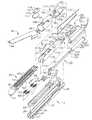
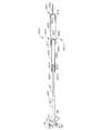
図面を参照すると、図面中では、同じ数字がいくつかの図面を通して、同じコンポーネントを示していて、図1は、いくつかの独自の利益を実践できる手術用ステープリングおよび切断器具10を示している。図1に示された実施の形態は、ハンドルアセンブリ300、細長いシャフトアセンブリ100、および細長いシャフトアセンブリ100に結合されたエンドエフェクター12を含んでいる。手術用装置のさまざまな実施の形態は、エンドエフェクターを含む場合があり、エンドエフェクターは、細長いシャフトアセンブリ100に旋回可能に取り付けられていて、ケーブルまたはバンドを曲げることによって、旋回するように駆動され、そのようなエンドエフェクターは、2006年1月10日に出願された米国特許出願第11/329,020号「関節接合したエンドエフェクターを備えた手術用器具(SURGICAL INSTRUMENT HAVING AN ARTICULATING END EFFECTOR)」に開示されていて、この米国特許出願の開示内容は、参照することによって、本明細書に組み込まれる。しかし、本明細書の詳細な説明が進むにしたがって、当業者は、本明細書に記載された手術用装置のさまざまな実施の形態が、異なる旋回機構および制御部を用いるエンドエフェクター構成と共に成功裡に実施される場合があり、そして、以下にさらに詳しく記載されるように、関節接合していないエンドエフェクター構成と共に成功裡に用いられる場合さえあることを理解するであろう。 Referring to the drawings, wherein like numerals indicate like components throughout the several views, FIG. 1 illustrates a surgical stapling and cutting
図1に見られるように、器具10のハンドルアセンブリ300は、閉鎖トリガ302、および発射トリガ310を含む場合がある。異なる手術作業に指向されたエンドエフェクターを備えた器具が、エンドエフェクターを操作するための異なる個数および種類のトリガまたは他の適切な制御部を有する場合があることは、理解されるであろう。エンドエフェクター12は、細長い形状が好ましいシャフトアセンブリ100によって、ハンドルアセンブリ300から離れて図示されている。臨床医は、関節接合制御部200を用いて、エンドエフェクター12をシャフトアセンブリ100に関して、関節をなして接合するようにする場合がある。 As seen in FIG. 1, the
さまざまな実施の形態では、複数のセンサーが、ハンドルアセンブリ300、細長いシャフトアセンブリ100、および/または、エンドエフェクター12における要素に結合されて、器具10のさまざまな機能を測定および記録し、器具のさまざまなコンポーネントの状態を記録し、ならびに、臨床医または使用者にフィードバック表示を提供するようにされている場合がある。器具10は、複数のセンサーを含み、この複数のセンサーは、例えば、閉鎖トリガセンサー、アンビル閉鎖センサー、アンビル閉鎖負荷センサー、ナイフ位置センサー、カートリッジ存在センサー(cartridge present sensor)、カートリッジ状態センサー、発射トリガセンサー、および弁作動センサー、または、それらの組み合わせなどを含む。他のセンサーは、関節角度センサー、アンビル位置センサー、発射力センサー、ロックアウト状態センサー、空気圧力センサー、流量センサー(flow rate sensor)、またはそれらの組み合わせなどを含む。各センサーは、手術用器具10の外面の近くに配された異なる接点と電気的に通信を行う場合がある。センサーは、閉鎖トリガ302および発射トリガ310に接続されて、閉鎖トリガおよび発射トリガの動作を検出するようになっている場合がある。センサーは、アンビル40の閉鎖、および、アンビル40への閉鎖負荷を測定するために用いられる場合がある。他のセンサーが、ナイフアセンブリ30(図2)の位置、ステープルカートリッジ50(図2)の存在、および/または、ステープルカートリッジ50の状態(例えば、使い切った、または、使い切っていない)を測定するために用いられる場合がある。その他のセンサーが、器具10のいたるところで、器具10の作動の回数、空気圧システムの圧力、空気圧式シリンダーまたは作動シリンダーの圧力、弁アクチエータを作動させるための可変流量などを測定するために用いられる場合がある。しかし、実施の形態は、この状況に限定されない。 In various embodiments, multiple sensors are coupled to elements in the
センサーの出力信号S1からSn(ここで、nは任意の正の整数)が、例えば、ハンドルアセンブリ内に配された電子制御モジュール603に供給される。電子制御モジュール603は、コントローラ、メモリ装置、バッテリー、測定回路、および/または、アクチエータを含み、アクチエータは、本明細書で以下に記載されるように、電気制御される可変流量空気圧式弁の閉鎖機構部分を制御する。しかし、実施の形態は、この状況に限定されない。Sensor output signals S1 to Sn (where n is any positive integer) are provided to an
垂直な、水平な、右の、左の、などのような、空間的な用語は、本明細書中では、手術器具10の長手方向の軸が、細長いシャフトアセンブリ100の中心軸と同軸であり、トリガ302、310がハンドルアセンブリ300の底部から鋭角で下向きに延びた状態であることを仮定して、図面に関して与えられていることが、理解されなければならない。しかし、実際には、手術用器具10は、さまざまな角度に配向される場合があり、したがって、これらの空間的な用語は、手術用器具10自体に対して用いられている。さらに、「近位の」は、ハンドルアセンブリ300の後ろに居てエンドエフェクター12を遠位に、つまり、自分から離して、位置させる臨床医の遠近感を表すために用いられている。 Spatial terms such as vertical, horizontal, right, left, etc. are used herein where the longitudinal axis of the
本明細書で用いられる場合、用語「加圧ガス」は、滅菌環境で用いられる空気圧動力式システムで用いるのに適した任意のガスを表す。そのような媒体の非限定的な例には、圧縮空気、二酸化炭素(CO2)、窒素、酸素、アルゴン、ヘリウム、水素化ナトリウム、プロパン、イソブタン、ブタンクロロフルオロカーボン、ジメチメエーテル、メチルエチルエーテル、亜酸化窒素、例えばHFA134a(1,1,1,2,−テトラフルオロエタン)またはHFA227(1,1,1,2,3,3,3−ヘプタフルオロプロパン)のようなハイドロフルオロアルカン(HFA)が含まれる。As used herein, the term “pressurized gas” refers to any gas suitable for use in a pneumatic powered system used in a sterile environment. Non-limiting examples of such media include compressed air, carbon dioxide (CO2 ), nitrogen, oxygen, argon, helium, sodium hydride, propane, isobutane, butane chlorofluorocarbon, dimethyl ether, methyl ethyl ether. Nitrous oxide, eg hydrofluoroalkanes (HFA) such as HFA134a (1,1,1,2, -tetrafluoroethane) or HFA227 (1,1,1,2,3,3,3-heptafluoropropane) ) Is included.
本明細書で用いられる場合、用語「流体連結された」は、要素が適切なラインまたは他の手段で一体に連結されていて、要素間を加圧ガスが通過できるようになっていることを意味する。本明細書で用いられる場合、「供給ライン」または「戻りライン」で用いられる用語「ライン」は、一つのコンポーネントから別のコンポーネントへ加圧ガスを移すための、硬質のもしくは柔軟な導管、パイプ、および/またはチューブから形成された適切な通路を示す。 As used herein, the term “fluidly connected” means that the elements are connected together by appropriate lines or other means so that pressurized gas can pass between the elements. means. As used herein, the term “line” as used in “supply line” or “return line” refers to a rigid or flexible conduit, pipe for transferring pressurized gas from one component to another. And / or a suitable passage formed from a tube.
本明細書で用いられる用語「空気圧信号」または「空気圧駆動信号」は、加圧ガスの供給源から、加圧ガスの供給源に流体連結された一つまたは複数のコンポーネントへのガスの流れ、または、相互に流体連結されたコンポーネントの間のガスの流れを示す。 As used herein, the term “pneumatic signal” or “pneumatic drive signal” refers to the flow of gas from a source of pressurized gas to one or more components fluidly coupled to the source of pressurized gas, Or, the flow of gas between components fluidly connected to each other.
本明細書で用いられる場合、語句「長手方向の軸に対して実質的に横方向の」の「長手方向の軸」は、シャフトの軸であり、「長手方向の軸に対して実質的に横方向の」とは、その長手方向の軸にほぼ垂直な方向を示している。しかし、長手方向の軸に対する垂直からある程度ずれた方向も、その長手方向の軸に対して実質的に横方向であることが、理解されるであろう。 As used herein, the phrase “longitudinal axis” in the phrase “substantially transverse to the longitudinal axis” is the axis of the shaft and “substantially relative to the longitudinal axis”. “Lateral” indicates a direction substantially perpendicular to the longitudinal axis. However, it will be understood that a direction deviating to some extent from normal to the longitudinal axis is also substantially transverse to the longitudinal axis.
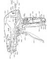
図2は、手術用器具10のさまざまな実施の形態で用いられる場合がある、ある種類の空気圧作動式、かつ電気制御されるツールアセンブリすなわちエンドエフェクターの分解組み立て図を示している。図1〜図4に示された空気圧操作作動式、かつ電気制御されるアセンブリ12は、エンドカッターとして作用するように構成されている。しかし、本明細書の詳しい説明が進むにしたがって、本発明の実施の形態のさまざまな独自かつ新規の駆動構成が、他の手術作業を実行するように構成された他のエンドエフェクターを駆動するためにも、おそらく用いられることができ、したがって、図面に示されたものからコンポーネントを除去、変更、または、追加することが必要となることが、理解されるであろう。さらに、図1〜図4に示されたエンドエフェクター12が具体的な手術への適用に応じて、改造される場合があることが、理解されるであろう。 FIG. 2 shows an exploded view of one type of pneumatically actuated and electrically controlled tool assembly or end effector that may be used in various embodiments of the
手術用器具10のさまざまな実施の形態と共に用いられる場合がある、ある種類のエンドエフェクターが図2に示されている。図2で見ることができるように、エンドエフェクター12は、Eビーム発射機構(ナイフアセンブリ)30を用いていて、この機構は、組織の切断、および、エンドエフェクター内に位置するステープルシリンダー内に配されたステープルの発射に加えて、ステープルシリンダーに対するエンドエフェクター12のアンビル40部分の間隔を有益に制御する。Eビーム発射機構のさまざまな態様が、シェルトン4世ら(Shelton, IV. et al.)に付与された米国特許第6,978,921号「Eビーム発射機構を組み込んだ手術用ステープリング器具(Surgical Stapling Instrument Incorporating An E-Beam Firing Mechanism)」に記載されていて、その米国特許の関連する部分は、参照することによって、本明細書に組み込まれる。しかし、本明細書の詳しい説明が進むにしたがって、当業者は、他のナイフおよび発射機構の構成が、本発明の実施の形態の全体の範囲を逸脱せずに有益に用いられる場合があることを、理解するであろう。 One type of end effector that may be used with various embodiments of the
本明細書で用いられる場合、用語「発射機構」は、空気圧作動式に電気制御されるツールおよび/またはエンドエフェクターの一部もしくはいくつかの部分を示し、これらの部分は、発射機構が本質的に静止している作動されていない位置から、それらの一部もしくはいくつかの部分が最終位置へ移動または再配置され終えている、作動された位置すなわち終了位置へ移動し、この最終位置では、それらの部分の最終位置への移動の結果として、エンドエフェクターへ加えられた少なくとも一回の発射動作に応じて、ツールが一回または複数回の動作を完了する。発射機構は、例えば、(i)空気圧作動式に電気制御されるツールによって完全に支持され、手術用装置内のコンポーネントと連結(interface)するコンポーネント、(ii)空気圧動力式ツール内および手術用装置内に配されたコンポーネントの組み合わせ、または、(iii)手術用装置によって支持され、空気圧作動式に電気制御されるツールの中および外への移動が可能なコンポーネント、を含む場合がある。本明細書で用いられる場合、用語「発射ストローク」は、作動されていない位置から作動された位置への発射機構の実際の動きを示す。用語「後退ストローク」は、発射機構が作動された位置から作動されていない位置へ戻る動きを示す。 As used herein, the term “fire mechanism” refers to a part or some part of a pneumatically actuated tool and / or end effector, which is essentially a fire mechanism. Move from a non-actuated position that is stationary to an activated position, or an end position, some or some of which have been moved or repositioned to a final position, As a result of the movement of these portions to their final position, the tool completes one or more operations in response to at least one firing operation applied to the end effector. The firing mechanism is, for example, (i) a component that is fully supported by a pneumatically actuated tool and interfaces with a component in the surgical device; (ii) in the pneumatically powered tool and the surgical device A combination of components disposed within, or (iii) a component supported by a surgical device and capable of moving in and out of a pneumatically electrically controlled tool. As used herein, the term “fire stroke” refers to the actual movement of the firing mechanism from an unactuated position to an actuated position. The term “retreat stroke” refers to the movement back from the position where the firing mechanism is activated to the position where it is not activated.
図2に見られるように、エンドエフェクター12は、遠位部材を含み、遠位部材は、さまざまな非限定的な実施の形態では、細長い導管20を含み、導管20は、導管に取り付けられた旋回式に移動可能なアンビル40を有する。細長い導管20は、ステープルカートリッジ50を受容し支持するように構成されていて、ステープルカートリッジ50はナイフアセンブリ30に反応して、ステープル70をアンビル40と形成接触させるよう押し出す。容易に交換可能なステープルカートリッジが本明細書で有益に記載されているが、本発明の態様に調和したステープルカートリッジが細長い導管20に永久的に固定されているまたは一体化されている場合があることが、理解されるであろう。 As seen in FIG. 2,
さまざまな実施の形態では、発射機構すなわちナイフアセンブリ30は、発射の間にエンドエフェクター12の間隔を制御する垂直方向に離れたピンを含んでいる。より詳しく言うと、上側ピン32は、アンビル40と細長い導管20との間のピボットの近くのアンビルポケット42に入るように場所を設定されている。図4を参照のこと。アンビル40が閉じられた状態で発射されると、上側ピン32は、アンビル40を通って遠位の向きに延びる長手方向のアンビルスロット44内を遠位の向きに進む。アンビル40のどのような小さい上向きのそりも、上側ピン32によって加えられる下向きの力によって抑えられる。 In various embodiments, firing mechanism or
ナイフアセンブリ30は、ナイフバーキャップ34をも含み、ナイフバーキャップ34は、細長い導管20内に形成された導管スロット23と上向きに噛み合い、それによって、上側ピン32と共に動作して、アンビル40および細長い導管20を、過剰な組織がアンビル40と導管20との間に挟まれた場合に、わずかに互いにより近づくように引く。さまざまな実施の形態で、ナイフアセンブリ30は、中間ピン36を有益に含み、中間ピン36は、カートリッジ50の下側面および細長い導管20の上側面に形成された発射駆動スロット(図示されていない)を通り、それによって、以下に記載されるように、スロット内のステープル70を押す。中間ピン36は、細長い導管20に対してスライドすることによって、エンドエフェクター12がその遠位の端部で締め付けられて閉じる傾向にも有益に対抗する。しかし、本発明のさまざまな実施の形態の独自かつ新規な態様が、他のナイフアセンブリ構成を用いることによって達成される場合がある。 The
ナイフアセンブリ30の上側ピン32および中間ピン36の間で遠位の側に設けられた切断エッジ38は、カートリッジ50の近位の側に設けられた垂直スロット54を通って移動し、挟まれた組織を切断する。ナイフアセンブリ30を細長い導管20およびアンビル40に関して積極的に位置設定することによって、有効な切断が実施されることが、確実になる。さまざまな実施の形態では、アンビル40の下側面には、複数のステープル形成ポケット(図示されていない)が設けられていて、複数のポケットは、ステープルカートリッジ50が細長い導管内に受容されたときに、ステープルカートリッジ50の上側面56の複数のステープル開口58に対応するように配列されている。さまざまな実施の形態では、ステープルカートリッジ50は、細長い導管20にスナップ嵌めされる場合がある。より詳しく言うと、ステープルカートリッジ50の拡張特徴部60、62が、細長い導管20の凹部24、26に、各々、摩擦によって、解除可能に、噛み合う。 The
図2にさらに見られるように、ステープルカートリッジ50は、カートリッジ本体51、ウエッジスレッド64、ステープルドライバー66、ステープル70、およびカートリッジトレイ68を含む。組み立てられると、カートリッジトレイ68は、ウエッジスレッド64、ステープルドライバー66、および、ステープル70を、カートリッジ本体51の内部に保持する。細長い導管20は、細長いシャフトアセンブリ100によって、ハンドルアセンブリ300に連結されていて、シャフトアセンブリ100は、遠位の背部すなわちフレーム部分110、および近位の背部すなわちフレーム部分130を含んでいる。細長い導管20は、近位の側に配された取り付けキャビティ22を有し、各取り付けキャビティ22は、遠位の背部分110の遠位の端部に形成された対応する導管固定部材114を受容する。細長い導管20は、アンビルカムスロット28をも有し、アンビルカムスロット28は、アンビル40の対応するアンビルピボット43を旋回可能に受容する。閉鎖スリーブアセンブリ170は、背部アセンブリ102を覆って受容され、遠位の閉鎖チューブ部分180および近位の閉鎖チューブ部分190を含む。以下に記載されるように、背部アセンブリ102に関する閉鎖スリーブアセンブリ170の軸方向の動きは、アンビル40に細長い導管20に関する旋回運動を起こさせる。 As further seen in FIG. 2, the
図2に見られるように、固定ばね112は、ナイフアセンブリ30に対するロックアウトとして、遠位の背部分110に取り付けられている。遠位の正方形開口111および近位の正方形開口113が、遠位の背部分110の上部に形成されていて、正方形開口の間にクリップバー115を画定し、そのクリップバー115は、固定ばね112の上部アーム116を受容し、固定ばね112の下側の遠位の向きに延びたアーム118は、以下により詳しく記載されるように、ナイフアセンブリ30から突出したピストンバー部分35を支持するシリンダーアセンブリ501の遠位の端部に下向きの力を加える。さまざまな実施の形態が、他の種類のロックアウトを含む場合があり、または、ロックアウトをまったく含まない場合があることが理解されるであろう。 As seen in FIG. 2, the fixed
図1〜図6に示された実施の形態では、エンドエフェクター12は、エンドエフェクター12をピボット104を中心にして引っぱるために曲げられるケーブルまたはバンドの集合によって、近位の閉鎖チューブ部分190(およびハンドルアセンブリ300)に対して、関節接合する場合がある。当業者は、そのような構成が、これらの種類の装置と共に用いられる場合がある多くの関節接合構成のほんの一つを表現したものであることを、理解するであろう。この実施の形態では、遠位の背部分110の近位の端部は、端部に設けられたボス122を有する。近位の背部分130の遠位の端部には、舌部134が設けられていて、舌部134は、舌部を貫通する開口136を有する。近位の背部分130は、開口136がボス122の開口124と同軸に並んでピボットピン138が開口136を通って延びることができるように、遠位の背部分110に関して配されている。図4を参照のこと。そのような構成は、組み立てられたとき、エンドエフェクター12がピボット軸A−Aを中心にして近位の背部分130に関して旋回できるようにする。 In the embodiment shown in FIGS. 1-6, the
上述したように、この実施の形態は、エンドエフェクター12を関節接合するためにバンドを用いる。より詳しく言うと、バンド150、160は、図2および図3に示されているように、関節ピボット104に向かって遠位の向きに延びている場合がある。バンド150は、近位の閉鎖チューブ部分190の左側面に沿って近位の閉鎖チューブ部分190を通って延びていて、バンド150はバンド160を避けて近位の閉鎖チューブ部分190の右側面に渡るように経路を定められている。そこで、バンド150は、例えば接続点123で、ボス122に機械的に連結されている場合がある。同様に、バンド160は、近位の閉鎖チューブ部分190の右側面に沿って近位の閉鎖チューブ部分190を通って延びていて、近位の閉鎖チューブ部分の右側面では、バンド160はバンド部材150を避けて近位の閉鎖チューブ部分190の左側面に渡るように経路を定められている。そこで、バンド160は、例えば接続点125で、ボス122に機械的に連結されている場合がある。 As described above, this embodiment uses a band to articulate the
図3は、閉鎖チューブアセンブリ100が破線で描かれた、エンドエフェクターおよび背部アセンブリ102の上面図である。図4は、器具10の同じ部分の部分的な側断面図である。図4に見られるように、バンド150およびバンド160は、ある非限定的な実施の形態に基づけば、互いにオフセットしていて、動きを妨害しないようになっている。例えば、バンド150は、バンド160よりも下側の位置にある状態で示されている。別の非限定的な実施の形態では、バンド150およびバンド160の垂直方向の位置は、逆である場合がある。図2および図3にさらに見られるように、バンド部材150は、近位のフレーム部分130の舌部134のピン140を囲うように延びている。同様に、バンド160は、近位のフレーム部分130の舌部分134のピン142を囲うように延びている。 FIG. 3 is a top view of the end effector and back assembly 102 with the
バンド部分150および160は、図5に示すように、ボス122から、近位の閉鎖チューブ部分190に沿って、関節制御部200まで延びている場合がある。関節制御部200は、関節スライド202、フレーム204、およびエンクロージャー206を含んでいる場合がある。バンド部分150、160は、スロット208またはその他の開口によって、関節スライド202を通過する場合があるが、バンド部分150、160は、任意の適切な手段によって関節スライド202に連結されている場合があることが、理解されるであろう。関節スライド202は、図5に示されているように、一部品である場合があり、または、ある非限定的な実施の形態では、2つの部品を含み、2つの部品の境界がスロット208を画定している場合がある。ある非限定的な実施の形態では、関節スライド202は、複数のスロットを含む場合があり、例えば、各スロットはバンド部分150、160の一つに対応している。エンクロージャー206は、制御部200のさまざまなコンポーネントを覆って、破片が入るのを防いでいる場合がある。
さまざまな実施の形態では、バンド部分150、160は、スロット208から見て近位の側に配された接続点210、212でフレーム204に固定されている場合がある。図5の非限定的な実施の形態は、バンド部分150、160が接続点210、212から、近位の閉鎖チューブ部分190の長手方向の軸の近くに配されたスロット208まで、予め曲げられていることを示している。バンド部分150、160が、ハンドルアセンブリ300を含めた、スロット208から見て近位の側に配された器具10のいずれかの場所に繋留されている場合があることが、理解されるはずである。 In various embodiments, the
使用時には、図2の実施の形態は、図3に示されているような関節が曲げられていない状態を有する場合がある。関節制御部200およびバンド150、160は、シャフトアセンブリ100の長手方向の軸に対しほぼ中央の位置にある状態で図示されている。したがって、エンドエフェクター12は、中間すなわち関節が曲げられていない位置にある。図6では、関節制御部200は、関節スライド202が関節フレームを通してシャフトアセンブリ100の右側面へ押された状態で、図示されている。したがって、バンド150、160は、シャフトアセンブリ100の右側面に向けて曲げられている。バンド150が右に曲げられていることによって、ボス122のピボット点からオフセットした横向きの力がボス122に加えられることが、分かる。このオフセットした力は、ボス122が関節ピボット104を中心にして旋回するようにし、次に、エンドエフェクター12を、図示されているように右に旋回させることになる。関節スライド202をシャフトアセンブリ100の左側面に向けて押すことが、両方のバンド150、160をシャフトアセンブリ100の左側面に向けて曲げる横方向の力をバンド150、160に加える場合があることが、理解されるであろう。次に、バンド160が曲がることによって、ボス122に横方向の力が加わり、その横方向の力は、上記のように、ボス122のピボット点からオフセットしている。ピボット点からオフセットした力が加わることが、次に、ボス122を関節ピボットを中心にして旋回させて、エンドエフェクター12を左に旋回させる。 In use, the embodiment of FIG. 2 may have an unbent joint as shown in FIG. The
さまざまな実施の形態で、シャフトアセンブリ100は、背部アセンブリ102に受容された閉鎖チューブアセンブリ170を含む。図2を参照のこと。閉鎖チューブアセンブリ170は、遠位の閉鎖チューブ部分180、および近位の閉鎖チューブ部分190を含む。遠位の閉鎖チューブ部分180、および、近位の閉鎖チューブ部分190は、ポリマーまたは他の適切な材料から製造されている場合がある。近位の閉鎖チューブ部分190は、中空で、近位の閉鎖チューブ部分を通って延びる軸方向通路191を有し、軸方向通路191は、その中に背部アセンブリ102の一部を受容するような寸法を有する。 In various embodiments, the
図2および図4に示された実施の形態では、二重ピボット閉鎖ジョイント172が用いられている。本発明が二重ピボット閉鎖ジョイントの構造に限定されず、任意の適切な閉鎖チューブまたはスリーブを含む場合があり、または、閉鎖チューブまたはスリーブをまったく含まない場合があることが理解されるであろう。図4を特に参照すると、遠位の閉鎖チューブ部分180は、近位の向きに突出した上側および下側舌部182、184を有する。遠位の閉鎖チューブ部分180は、アンビル40のアンビル開/閉タブ46と噛み合うための蹄鉄開口185およびタブ186をさらに含んでいて、以下に詳しく記載されるように、アンビル40を開位置および閉位置の間で旋回させる。 In the embodiment shown in FIGS. 2 and 4, a double pivot closure joint 172 is used. It will be appreciated that the present invention is not limited to the construction of a double pivot closure joint and may include any suitable closure tube or sleeve, or may not include any closure tube or sleeve at all. . With particular reference to FIG. 4, the distal
近位の閉鎖チューブ部分190には、同様に、遠位の向きに延びた上側舌部192、および遠位の向きに延びた下側舌部194が設けられている。上側二重ピボットリンク174は、上向きに突出した遠位および近位のピボットピン175、176を含み、それらのピボットピンは、各々、上側の近位の向きに突出した舌部182における上側の遠位のピン開口183、および、上側の遠位の向きに突出した舌部192における上側の近位のピン開口193に噛み合う。接合部の構成は、下側二重ピボットリンク177をさらに含み、そのピボットリンクは、下向きに突出した遠位および近位のピボットピン178、179(図2には示されていないが、図4を参照のこと)を有し、それらのピボットピンは、各々、下側の近位の向きに突出した舌部184における下側の遠位のピン開口187、および、下側の遠位の向きに突出した舌部194における下側の近位のピン開口195に噛み合う。 The proximal
使用中に、閉鎖チューブアセンブリ170は、例えば、閉鎖トリガ302の作動に反応して、遠位の向きに移動して、アンビル40を閉鎖する。アンビル40は、背部アセンブリ102上で閉鎖チューブアセンブリ170を遠位の向きに移動させることによって、閉鎖され、その閉鎖チューブアセンブリ170の移動は、蹄鉄開口185の背面がアンビル40の開/閉タブ46に突き当たり、アンビル40を閉じた位置へ旋回させるようにする。アンビル40を開くためには、閉鎖チューブアセンブリ170は、背部アセンブリ102上で近位の向きに軸方向で動かされ、タブ186を開/閉タブ46に接触させタブ46を押すようにさせて、アンビル40を開いた位置へ旋回させる。ある実施の形態では、センサーが閉鎖チューブアセンブリ170内に配されていて、アンビル40の開/閉タブ46に突き当たり、アンビル40を閉じた位置に旋回させ、かつアンビル40を閉じた位置に維持するために、蹄鉄開口185に加えられる力を測定する。 In use,
図7は、手術用装置のさまざまな実施の形態の非限定的なハンドルアセンブリ300の分解組立て図である。図7に示された実施の形態では、ハンドルアセンブリは、「ピストルグリップ」構造を有し、右手側ケース部材320および左手側ケース部材330から形成されていて、これらのケース部材は、ポリマーまたは他の適切な材料で成型され、または別様に製造されていて、相互に嵌め合わされるように設計されている。そのようなケース部材320および330は、成型されたスナップ特徴部、ペグ、およびソケット、または接着剤、ねじ、ボルト、および/または、クリップによってケース部材に別様に形成されたスナップ特徴部、ペグ、およびソケットによって、相互に取り付けられる場合がある。右手側ケース部材320の上側部分322は、左手側ケース部材330の対応する上側部分323と嵌め合わされて、符号340が付された主ハウジング部分を形成する。同様に、右手側ケース部材320の下側グリップ部分324は、左手側ケース部材の下側グリップ部分334と嵌め合わされて、全体に符号342が付されたグリップ部分を形成する。図7に示された実施の形態では、グリップ部分342の全体は、主ハウジング部分340と一体化されている。そのような構成は、加圧ガスの供給源がグリップ部分342内に永久的に据え付けられている用途に特によく適している場合がある。そのような構成は、ハンドルアセンブリ300の外部に配され、かつハウジングアセンブリの一つまたは複数のポートを通してハンドルアセンブリ内に収容された制御コンポーネントに差し込まれる、加圧ガスの供給源と共に用いるのにも適している。他の実施の形態では、以下にさらに詳しく記載されるように、グリップ部分342は、主ハウジング部分340から取り外し可能である。本明細書の詳しい説明が進むにしたがって理解されるであろうように、そのような構成は、無数の利点および利益を提供する。しかし、当業者は、ハンドルアセンブリ300がさまざまな異なる形状および寸法で提供される場合があることを、容易に理解するであろう。 FIG. 7 is an exploded view of a
明瞭にする目的のために、図7は、最終的にアンビル40の開閉を制御する閉鎖チューブアセンブリ170の軸方向の動きを制御するために用いられるコンポーネントのみを示している。図7に見られるように、連結アセンブリ430によって閉鎖トリガ302に連結された閉鎖シャトル400は、主ハウジング部分340内に支持されている。閉鎖シャトル400も、2つの部品402、404で製造されている場合があり、それらの部品は、ポリマーまたは他の適切な材料で成型もしくは別様に製造されていて、相互に嵌め合わされるように設計されている。例えば、図7に示された実施の形態では、右手側部分402には、左手側部分404内の対応するソケット(図示されていない)内に受容されるように設計された締結具ポスト403が設けられている場合がある。右手および左手側部分402、404は、別に、スナップ部材、および/または、接着剤、および/または、ボルト、ねじ、および/または、クリップ、で相互に維持されている場合がある。図7に見られるように、維持溝196が近位の閉鎖チューブ部分190の近位の端部に設けられている。閉鎖シャトル400の右手側部分402は、右維持フランジ部分405を有し、右維持フランジ部分405は、閉鎖シャトル400の左手部分404の左維持フランジ部分(図示されていない)と共に動作するように構成されていて、近位の閉鎖チューブ部分190内の維持溝196内に延びる維持フランジアセンブリを形成している。 For purposes of clarity, FIG. 7 shows only the components used to control the axial movement of the
図7にさらに見られるように、右背部アセンブリ維持ペグ326は、右手側ケース部材320から内向きに突出している。そのペグ326は、閉鎖シャトル400の右手側部分402の細長いスロットまたは窓406内に突出している。同様の閉鎖シャトル維持ペグ(図示されていない)が、閉鎖シャトル400の左手側部分404に設けられたもう一つの窓またはスロット408に受容されるように、左手側ケース部材330から内向きに突出している。維持ペグは、閉鎖シャトル400がハンドルアセンブリ300に関して軸方向に動けるようにしながら、近位の背部分130(図7には示されていない)の近位の端部133をハンドルアセンブリ300に動かないように固定するのに役立つ。維持ペグは、例えば、ボルト、ねじ、接着剤、および/または、スナップ特徴部などによって、近位の背部分130の近位の端部に機械的に取り付けられている場合がある。さらに、閉鎖シャトル400には、横方向に延びるガイドレール410、411が設けられている。レール410は、右手側ケース部材320のレールガイド328内にスライド式に受容されるように構成されていて、レール411は、左手側ケース部材330のレールガイド(図示されていない)内にスライド式に受容されるように構成されている。 As further seen in FIG. 7, the right back
閉鎖シャトル400および閉鎖チューブアセンブリ170の遠位の向き(矢印C)での軸方向の動きは、閉鎖トリガ302をハンドルアセンブリ300のグリップ部分342へ向けて動かすことによって、生み出され、閉鎖シャトル400の近位の向き(矢印D)での軸方向の動きは、閉鎖トリガ302をグリップ部分342から離れるように動かすことによって、生み出される。さまざまな実施の形態で、閉鎖シャトル400には、閉鎖シャトル400への閉鎖連結アセンブリ430の取り付けを容易にするコネクタタブ412が設けられている。図8および図9を参照のこと。閉鎖連結アセンブリ430は、ピン414によってコネクタタブ412に旋回可能に留められたヨーク部分432を含んでいる。閉鎖連結アセンブリ430は、図7に示されているように、閉鎖ピン436によって、閉鎖トリガ302に形成されたヨークアセンブリ304に旋回可能に留められている閉鎖アーム434をさらに有する。閉鎖トリガ302は、ピボットピン306によってハンドルアセンブリ300内に旋回可能に取り付けられていて、ピボットピン306は、右手側ケース部材320と左手側ケース部材330の間に延びている。 The axial movement of the
臨床医が、アンビル40を閉じて、エンドエフェクター12内に組織を挟むことを望む場合、臨床医は、閉鎖トリガ302をグリップ部分342に向けて引く。臨床医が閉鎖トリガ302をグリップ部分342に向けて引くと、閉鎖連結アセンブリ430は、図8に示されているように、閉鎖連結アセンブリ430が固定位置に移動するまで、遠位の向きの「C」の向きに閉鎖シャトル400を動かす。連結アセンブリ430は、固定位置にある場合、閉鎖シャトル400をその固定位置に維持する傾向を有する。閉鎖シャトル400が固定位置に動かされると、閉鎖チューブアセンブリ170は、背部アセンブリ102上を遠位の向きに動かされ、アンビル40の開/閉タブ46が遠位の閉鎖チューブ部分180の蹄鉄開口185の近位の端部によって接触されるようにし、それによって、アンビル40を閉じた(挟まれた)位置へ旋回させる。 If the clinician wishes to close the
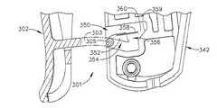
さまざまな実施の形態で、閉鎖シャトル400を閉じた位置に維持するために、閉鎖トリガ302には、解除可能な固定機構301が設けられている場合があり、その解除可能な固定機構301は、グリップ部分342と噛み合い、閉鎖トリガ302を固定位置に解除可能に維持するように構成されている。別の固定装置も、閉鎖シャトル400を固定位置に解除可能に維持するために用いられる場合がある。図8、図8A、図8B、および、図9に示された実施の形態では、閉鎖トリガ302は、柔軟な長手方向のアーム303を含み、アームはそこから延びる横方向ピン305を含んでいる。そのアーム303およびピン305は、例えば、成型プラスチックから作られている場合がある。ハンドルアセンブリ300のピストルグリップ部分342は、開口350を含み、開口350は、開口内に配された横方向に延びるウエッジ352を備えている。閉鎖トリガ302が後退させられると、ピン305がウエッジ352と噛み合い、ピン305がウエッジ352の下側面354によって下向きに押される(つまり、アーム303が時計方向に旋回させられる)。ピン305が下側面354を完全に通過すると、アーム303への時計方向の力が取り除かれ、ピン305は反時計方向に旋回させられて、ピン305がウエッジ352の背後のノッチ303に位置するようになり、それによって、閉鎖トリガ302を固定する。ピン305は、さらに、ウエッジ352から延びる柔軟な停止部358によって固定位置での所定の位置に保持される。 In various embodiments, the
閉鎖トリガ302を固定解除するためには、操作者は、閉鎖トリガ302をさらに引き、ピン305を開口350の傾斜後壁359に噛み合わさせて、ピン305が柔軟な停止部358を越えるようにピン305を上向きに押す。そうすると、ピン305は、開口360の上側導管を通って自由に移動するようになり、閉鎖トリガ302はもはやピストルグリップ部分342に固定されない。そのような構成のさらなる詳細は、2006年1月31日に出願されたシェルトン四世ら(Shelton, IV et al.)による米国特許出願第11/344,020号「取り外し可能なバッテリーを備えた手術用器具(Surgical Instrument Having A Removable Battery)」に見出すことができ、その米国特許出願の関連する部分は、参照することによって、本明細書に組み込まれる。他の解除可能な固定構成も用いられる場合がある。 To unlock the
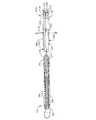
手術装置のさまざまな実施の形態では、ナイフアセンブリ30は、ナイフアセンブリから突出した、または別様にナイフアセンブリに取り付けられたほぼ硬質のピストンバー部分35を有する場合があり、ピストンバー部分35は駆動部材500の一部であり、その駆動部材は、遠位の背部分110によって作動可能に支持され、そして、少なくとも2つの作動の動き(例えば、発射動作および後退動作)をナイフアセンブリ30に加えるように構成されている。図3、図4、図10、および、図11に示された実施の形態では、駆動部材500は、2ステージ空気圧作動式シリンダーアセンブリ501を含んでいる。ナイフアセンブリ30は、一体のコンポーネントを含む場合があり、または、器具10のより容易な組み立てを促進するために複数の部品から構成されている場合がある。例えば、図10および図11に示されているように、ナイフバーアセンブリ30は、遠位の部分31を含み、遠位の部分31は、上側ピン32、キャップ34、中間ピン36、および、ナイフ38を収容している。遠位の部分31には、ピストンバー部分35の遠位の端部に設けられた突出部37を受容するような寸法の開口33が遠位の端部31内に設けられている場合がある。突出部37は、開口33内に摩擦を伴って受容され、また/または、接着剤および/もしくは溶接によって、開口33内に維持されている場合がある。 In various embodiments of the surgical device, the
シリンダーアセンブリ501は、第1のシリンダーハウジング510を含み、第1のシリンダーハウジング510は、第1の閉じた近位の端部512および第1の開いた遠位の端部514を有し、第1の開いた遠位の端部514は、第1のシリンダーハウジング510内の第1の軸方向通路516内に向けて開いている。シリンダーアセンブリ501は、第2のシリンダーハウジング520をも含み、第2のシリンダーハウジング520は、第2の閉じた近位の端部522および第2の開いた遠位の端部524を有し、第2の開いた遠位の端部524は、第2の軸方向通路526内に向かって開いている。第2の閉じた近位の端部522は、第2の閉じた近位の端部522に形成された第1のピストンヘッド528を有し、第1のピストンヘッド528は、第1の近位の端部512の遠位の側面と第1のピストンヘッド528の近位の側面との間に第1のシリンダー領域515を画定するように、第1のシリンダーハウジング510の第1の壁511をほぼ気密にスライド密閉するために、第1の軸方向通路516に関連して寸法を決められている。第1のシリンダーハウジング510の第1の遠位の端部514は、第1の遠位の端部514に形成された内向きに延びる第1のフランジ517をさらに有し、第1のフランジ517は、第1のフランジ517の近位の側面と第1のピストンヘッド528の遠位の側面との間に第2のシリンダー領域518を画定するように、第2のシリンダーハウジング520の外壁面をほぼ気密にスライド密閉する。 The
第1の通路527が、第1のピストンヘッド528を通って設けられている。図10および図11でさらに見られるように、ピストンバー35の近位の端部は、第2のシリンダーハウジング520の第2の開いた遠位の端部524を通って第2の軸方向通路526内まで延びている。第2のピストンヘッド530は、ピストンバー35の近位の端部の表面に形成されているか、または近位の端部に別様に取り付けられている。第2のピストンヘッド530は、第3のシリンダー領域532を画定するように第2のシリンダーハウジング520の第2の壁521をほぼ気密にスライド密閉するために、第2の軸方向通路526に関連して寸法を決められている。第2のシリンダーハウジング520の第2の遠位の端部524は、この遠位の端部524に形成された内向きに延びる第2のフランジ525をさらに有し、第2のフランジ525の近位の側面と第2のピストンヘッド530の遠位の側面の間に第4のシリンダー領域534を画定するように、ピストンバー35をほぼ気密にスライド密閉する。 A
図3および図4に見られるように、シリンダーアセンブリ501は、遠位の背部分110内に取り付けられている。さまざまな実施の形態では、一対のトラニオン519が、第1のシリンダーハウジング510の近位の端部に設けられている。トラニオン519は、遠位の背部分110のトラニオンボア119内に受容されて、シリンダーアセンブリ501がピボット軸B−Bを中心に遠位の背部分110内で旋回できるようにしている。図3を参照のこと。第1の供給ラインすなわち供給コンジット540は、ハンドルアセンブリ300内の方向制御弁610(図8および図9)から、第1のシリンダーハウジング510の第1の近位の端部512に連結されるように近位の閉鎖チューブ部分190を通って延びていて、加圧ガスを、第1の供給ポート513を通して、または、第1のシリンダーハウジング510の第1の近位の端部512の開口を通して、供給する。図10および図11を参照のこと。ある実施の形態では、圧力センサーが、第1の供給ライン540内の圧力(P)を測定または感知するために、第1の供給ライン540に流体連結されている場合がある。圧力センサーは、電気フィードバック信号を、電子制御モジュール603に供給し、その電気フィードバック信号は、第1の供給ライン540内の圧力に比例している。加えて、第2の供給ライン542が、方向制御弁610から、近位の閉鎖チューブ部分190を通って延びていて、第1のシリンダーハウジング510の遠位の端部514に隣接したところで第1のシリンダーハウジング510に結合されていて、加圧ガスを第2のポート529を通して第2のシリンダー領域518内に供給する。ある実施の形態では、圧力センサーが、第2の供給ライン542と流体連結されている場合があり、第2の供給ライン542内の圧力(P)を測定または感知するようになっている。圧力センサーは、電気フィードバック信号を電子制御モジュール603に供給し、その電気フィードバック信号は、第2の供給ライン542内の圧力に比例する。他の圧力センサーが、空気圧システムのいたるところに流体連結されている場合がある。例えば、圧力センサーは、第1および第2の圧力供給ポート513、529のそれぞれに流体連結され、対応する第1および第2のシリンダー領域515、518内の圧力を測定するようになっている場合がある。このようにして、2ステージシリンダーアセンブリ501内の圧力は、電子制御モジュール603へのフィードバック信号として、測定され供給される場合がある。 As seen in FIGS. 3 and 4, the
図8〜図11および図26を参照すると、発射機構すなわちナイフアセンブリ30の伸長および後退が、ここで説明される。図8および図9に見られるように、供給ライン540および542は、電気制御される方向弁610に連結されていて、電気制御される方向弁610は、ハンドルハウジング350内に収容されたアクチエータシステム600の一部である。アクチエータシステム600は、作動トリガ670、方向弁610、および電気制御される可変流量空気圧弁660を含んでいる。これらの要素は、電子制御モジュール603に連結されている。電子制御モジュール603は、器具10のいたるところに分布したさまざまなセンサーからのフィードバック信号を受信する。電子制御モジュール603は、フィードバック信号に基づいて、器具10のいたるところに分布したさまざまな制御要素に制御信号を供給する。ある実施の形態では、電子制御モジュール603は、コントローラ702、メモリ装置703、バッテリー704、測定回路732、および/または、電気制御される可変流量空気圧弁660の一部である閉鎖機構730を制御するためのアクチエータ706を含む。図26を参照のこと。しかし、実施の形態は、この状況に限定されない。ある実施の形態では、アクチエータシステム600は、状態モジュール2408(図33〜図37を参照して以下に記載される)と通信を行う場合がある。さまざまな実施の形態では、方向弁610は、電子制御モジュール603によって電気的に制御される場合がある。別の実施の形態では、方向弁は、ハンドルハウジング350を通してアクセス可能なセレクタースイッチ612またはプッシュボタンによって、前進(伸長)位置および反転(後退)位置の間を手動で切り替えられる場合がある。ある実施の形態では、セレクタースイッチ612または適切なボタンが、電気的な形態で実現され、方向弁610の望ましい状態を表示する信号を生み出す場合がある。信号は、コントローラ702に連結される場合があり、コントローラ702は、方向弁610を制御するための弁方向制御信号を生み出す。図8および図9に示された実施の形態では、加圧ガスの取り外し可能な供給源620が用いられる。以下により詳しく記載されるように、加圧ガスのそのような供給源は、シリンダー622を含み、シリンダー622は、好ましい加圧ガスで再充填可能な場合がある。しかし、当業者は、加圧ガスの交換不可能/再充填不可能な供給源(シリンダー)も、有効に用いられる可能性があることを、理解するであろう。さらに別の実施の形態では、ハンドルアセンブリ300には、加圧ガスの外部の供給源618から加圧ガスを供給するためのポート616が設けられている場合がある。例えば、器具10は、柔軟な供給ライン617を通して施設の圧縮空気供給源618に連結されることもある。図8Bを参照のこと。ある実施の形態では、圧力センサーが、入力供給ライン650内の圧力を測定または感知するために、取り外し可能な供給源622または施設の圧縮空気供給源618の出口ポートに流体連結されている場合がある。圧力センサーは、電気フィードバック信号を、電子制御モジュール603に供給し、その電気フィードバック信号は、入力供給ライン650内の圧力に比例する。 With reference to FIGS. 8-11 and 26, the extension and retraction of the firing mechanism or
取り外し可能/再充填可能なシリンダー622の独自のそして新規な態様が、以下にさらに記載される。しかし、ピストンバー35およびナイフアセンブリ30の伸長および後退を説明する目的のために、加圧ガスがシリンダー622(または外部の圧力源618)から、供給ライン650を通って、電気制御される可変流量空気圧弁660に流れることが分かる。電気制御される可変流量空気圧弁660は、コントローラ702によって制御される。図9に最も詳しく示されているように、可変流量空気圧弁660は、弁作動センサー662に連結されていて、弁作動センサー662は、作動トリガ670によって作動される。弁作動センサー662は、コントローラ702に連結されたデジタルまたはアナログセンサーである場合がある。図示された実施の形態では、弁作動センサー662は、電気制御される可変流量空気圧弁660を通る望ましい流量に比例する電気信号を出力する比例センサーである。弁作動センサー662が作動トリガ670の動きを検出すると、センサーはコントローラ702に電気信号を送り、その電気信号は、シリンダー662から供給ライン680内へそして第1または第2の供給ライン540、542へ流れる加圧ガスの望ましい流量に比例する。コントローラ702は、可変流量空気圧弁660内の流量制御要素を調節して、望ましい流量の加圧ガスを生み出す。ある実施の形態では、圧力センサーが、供給ライン680内の圧力を測定または感知するために、供給ライン680に流体連結されている場合がある。圧力センサーは、電気フィードバック信号を電気制御モジュール603に供給し、その電気フィードバック信号は、供給ライン680内の圧力に比例する。本明細書で用いる場合、用語「可変流量作動アセンブリ」は、少なくとも、可変流量空気圧弁660、作動トリガ670、コントローラ702、バッテリー704、アクチエータ706、および、それらに相当する構造物を含んでいる。 A unique and novel embodiment of the removable /
弁作動センサー662(図22Aおよび図22B)は、作動トリガ670との通信を行い、いつ作動トリガ670が操作者によってハンドルの下側グリップ部分324に向けて引かれ終え(すなわち「閉じられ」終え)、それによって、切断/ステープリング動作が電気制御された方式でエンドエフェクター12によって空気圧式に作動されたかを検出する。弁作動センサー662は、例えば、レオスタットすなわち可変抵抗器のような、比例センサーである場合がある。作動トリガ670が引かれると、弁作動センサー662は、その動きを検出し、電気信号をコントローラ702および/またはメモリ装置703に送り、その電気信号は空気圧システムを通る望ましい圧力または流量を表示している。コントローラ702は、電気作動信号をアクチエータ706に送り、可変流量空気圧弁660を通る流量を制御する。弁作動センサー662が可変抵抗器またはその類似物である場合、作動信号は作動トリガ670の動きの量にほぼ比例する場合がある。したがって、もし操作者が作動トリガ670をほんの少しだけ引くまたは閉じると、作動信号は、ゆえに、流量は、比較的少ない。作動トリガ670が十分に引かれる(すなわち、完全に閉じた位置にある)と、作動信号は、ゆえに、流量は、その最大値になる。言い換えれば、使用者が作動トリガ670を強く引くほど、作動信号はより大きくなり、より大きな流量が可変流量空気圧弁660を流れるようになる。 The valve actuation sensor 662 (FIGS. 22A and 22B) communicates with the
アクチエータ706は、電気モーター、適切なギア減速機、空気圧アクチエータ、ソレノイド、圧力アクチエータといった装置、および、電子または圧縮空気のようなポテンシャルエネルギーの源を、閉鎖機構730(図24)を駆動するのに適した物理的な変位(displacement)に変換できる任意の他の適切な装置、を含む任意の適切な種類の作動機構を含む場合がある。
図22Aおよび図22Bは、比例センサーのさまざまな実施の形態を示している。図示された実施の形態では、図22Aおよび図22Bは、器具のさまざまな実施の形態に基づく弁作動センサー662として用いられる場合がある比例センサーの2つの状態を示している。弁作動センサー662は、表面部分708、第1の電極(A)710、第2の電極(B)712、および、例えば電気的活性ポリマー(EAP)のような電極710、712間の圧縮可能な誘電材料部714を含んでいる場合がある。弁作動センサー662は、作動トリガ670が後退したときに、表面部分708が作動トリガ670と接触するように、配されている場合がある。したがって、作動トリガ670が後退させられたとき、誘電材料部714が図22Bに示されているように圧縮され、電極710、712が互いにより近くなる。電極710、712間の距離「b」は、電極710、712間のインピーダンスに直接関連しているので、距離が大きいほどインピーダンスが大きくなり、距離が短いほど、インピーダンスが小さくなる。そのようにして、誘電体714が作動トリガ670の後退(図22Bの力「F」として示された)に起因して圧縮される量は、電極710、712間のインピーダンスに比例し、このことを、可変流量空気圧弁660を比例的に制御するのに用いることができる。 22A and 22B show various embodiments of the proportional sensor. In the illustrated embodiment, FIGS. 22A and 22B illustrate two states of a proportional sensor that may be used as a
図23は、器具10のさまざまな実施の形態に基づく器具10の電気回路のある実施の形態の模式図である。操作者が最初に閉鎖トリガ302を固定した後に発射トリガ310を引くと、作動センサー662が、作動トリガ670を引くことによって、作動される。作動センサー662の作動によって、圧縮ガスがアクチエータ706およびコントローラ702の制御の下で可変流量空気圧弁660を通って流れることができるようになる。通常開のストローク終了センサー(end-of-stroke sensor)716が開いている場合(エンドエフェクターのストロークの終了にまだ到達していないことを意味する)、加圧ガスは第1の供給導管540を通って可変流量空気圧弁660を通って流れることになる。センサースイッチ716が通常開で、センサースイッチ716が閉じていないので、リレー720のインダクタ718は励磁されず、したがって、リレー720はその非励磁状態にあることになる。回路は、カートリッジロックアウトセンサー722をも含んでいる。エンドエフェクター12がステープルカートリッジ50を含む場合、センサー722は閉じた状態にあることになり、電流が流れることができる。そうではなく、エンドエフェクター12がステープルカートリッジ50を含まない場合、センサー722は、開き、それによって、バッテリー704が電力をアクチエータ706に供給するのが防止される。 FIG. 23 is a schematic diagram of an embodiment of an electrical circuit of the
ステープルカートリッジ50が存在すると、センサー722は閉じられて、単極単投リレー724を励磁する。リレー724が励磁されると、電流がリレー724を通って流れ、そして、弁作動センサー662(可変抵抗器として図示されている)を通って流れる。論理回路726は、センサースイッチ716、リレー720、センサー722、単極単投リレー724、および、弁作動センサー662からの入力を受け取り、コントローラ702へデジタル形式で情報を供給する。コントローラ702は、その情報を用いて、制御信号746(図24)を生み出し、方向制御弁610への作動を維持し、加圧ガスが第1の供給ライン540を流れることができるようにし、エンドエフェクターが近位の端部から遠位の端部への前進方向を維持するようにする。 When the
エンドエフェクター12がそのストロークの終わりに到達すると、センサースイッチ716が作動させられ、それによって、リレー720が励磁される。これによって、リレー720はその励磁された状態(図23には示されていない)を呈することになり、リレー720が励磁されたことにより、電流がカートリッジロックアウトセンサー722および弁作動センサー662を迂回して流れるようになる。こうして、コントローラ702は、方向制御弁610を制御信号796(図24)を用いて作動させ、加圧ガスが第2の供給ライン542を流れるようにし、エンドエフェクターが遠位の端部から近位の端部への向きで戻るようにする。 When
ストローク開始センサー728は、通常閉なので、電流はインダクタ718に戻って流れ、ストローク開始センサー728が開くまで、センサー728を閉じた状態に保つ。ナイフアセンブリ30が十分に後退させられると、ストローク開始センサー728は、作動させられ、センサー728が開かれる。次に、コントローラ702は、アクチエータ706に可変流量空気圧弁660を遮断させる信号を出力する。 Since stroke start sensor 728 is normally closed, current flows back to
他の実施の形態では、アナログ比例タイプの弁作動センサー662ではなく、デジタルのオン・オフタイプのセンサーが代わりに用いられる場合がある。そのような実施の形態では、閉鎖機構730は、操作者によって加えられる力にほぼ依存せずに、その最大流量能力まで開き、または、ゼロ流量になるよう遮断する。完全に開いた状態では、可変流量空気圧弁660は、ほぼ一定の流量を提供する。操作者は、依然として力のフィードバックを経験するが、その理由は、発射トリガ670がギア駆動列に連動させられているからである。 In other embodiments, instead of an analog proportional type
ここで図8〜図11を再び参照すると、さまざまな実施の形態で、作動トリガ670は、発射トリガ310に隣接して支持されていて、発射トリガ310は、右手側ケース部材320と左手側ケース部材330との間に延びているピボットピン370によってハンドルアセンブリ300に旋回可能に連結されている。作動トリガ670を内向きに発射トリガ310に向けて引くことによって、弁作動センサー662が作動させられ、コントローラ702に比例信号が与えられ、アクチエータ706が調節され、それによって、可変流量空気圧弁660が調節され、シリンダー622から、方向弁610に連結された供給ライン680へ流れる加圧ガスの流量が増加する。方向弁610の位置に応じて、加圧ガスは供給ライン540または供給ライン542のいずれかに流れ込む。例えば、方向弁610が臨床医によってナイフアセンブリ30が発射されるように作動されると、加圧ガスはコントローラ702によって制御された流量で可変流量空気圧弁660を通って供給ライン540へ、第1のピストンヘッド528の第1の開口527を通って第1のシリンダー領域515内へ、そして、作動トリガ670の作動時に、第3のシリンダー領域532内へ、流れることができるようになる。ある実施の形態では、圧力センサーは、第1のピストンヘッド528に流体連結されていて、第1のピストンヘッド528での圧力を感知および測定する。加圧ガスが第3のシリンダー領域532に流入すると、第2のピストンヘッド530は、ピストンバー35を遠位の向きに押す。ある実施の形態では、圧力センサーは、第2のピストンヘッド530にも流体連結されていて、第2のピストンヘッド530での圧力を感知および測定する。第4のシリンダー領域内に配されたガスは、第2のシリンダーハウジング520内の排気開口523を通して第4のシリンダー領域から排出される。同様に、第2のシリンダー領域518内に収容されたガスは、第2の供給ライン542に向かう第2の開口529を通して第2のシリンダー領域518から排出されるようになっている。第2の供給ライン542は、排出されたガスを方向弁610へ運び、方向弁610では、排出されたガスは最終的に方向弁610から排出される。加圧ガスを第1のシリンダー領域515および第3のシリンダー領域532に続けて加えることによって、ナイフアセンブリ30は、エンドエフェクター12を通って完全に伸長することになる。ナイフアセンブリ30がエンドエフェクター12を通過すると、ナイフアセンブリ30はエンドエフェクターに挟まれた組織を切断し、ステープルカートリッジ50内のステープル70を発射する(ステープルをアンビル40の下側面と接触させて形成するように押し出す)。一旦ナイフアセンブリ30が、エンドエフェクター12内でのナイフアセンブリ30の最も遠位の位置に進み終えると、臨床医は作動トリガ670を解放して、加圧ガスを加えることを停止する。 Referring again to FIGS. 8-11, in various embodiments, the
発射機構すなわちナイフアセンブリ30を後退させるために、臨床医は、方向弁610を後退位置に調節するためにセレクタースイッチ612または適切なボタンを手動で動かし、作動トリガ670を引き始め、それによって、圧縮ガスを第2の供給ライン542内に流すようにする。第2の供給ライン542を流れるガスは、第2のシリンダー領域518内に入り、それによって、第2のシリンダーハウジング520が第1のシリンダーハウジング510内に近位の向きに後退する。第1のシリンダー領域515内のガスは、第1の供給開口513を通って第1の供給ライン540内に排出されることができるようになる。第1の供給ライン540を通るガスは、方向弁610に入り、方向弁610ではガスが方向弁610から排出される。一旦第2のシリンダー領域518に入る加圧ガスが、第2のシリンダーハウジング520を、図10に示すように、第1のシリンダーハウジング510内に後退させると、第2の開口529を通るガスは、こんどは、第1のシリンダーハウジング510内の排気開口523を通って第4のシリンダー領域534内に流れ込むことができるようになる。加圧ガスが第4のシリンダー領域534に入ると、第2のピストンヘッド530は、ピストンバー35を第2のシリンダーハウジング520内に近位の向きに引く。第3のシリンダー領域532内のガスは、第1の開口527を通って第1のシリンダー領域515内に流れ込み、第1のシリンダー領域515からはガスが上述したように排気される。 To retract the firing mechanism or
器具のさまざまな実施の形態の可変流量空気圧弁660の形態の可変流量弁は、可変流量空気圧弁660を作動されていない位置へ付勢(bias)するために、さまざまな電気制御要素またはコンポーネント(図示されていない)を用いる場合がある。作動されていない位置にあるとき、可変流量空気圧弁660は、可変流量空気圧弁660のオリフィス(図示されていない)を通してガスの供給源620、618からのいずれのガスの流れも阻止するように構成されている場合がある。したがって、アクチエータトリガ670が作動されていない位置にあるとき、装置は本質的にオフ状態である。 A variable flow valve in the form of a variable flow
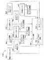
図24は、電気制御される空気圧システム700のある実施の形態を示している。空気圧システム700は、加圧ガスの内部または外部供給源を含んでいる。図示された実施の形態では、空気圧システム700は、加圧ガスの供給源としてシリンダー622を含み、シリンダー622は好ましい加圧ガスを再充填可能である場合がある。加圧ガスの交換不可能/再充填不可能な供給源(シリンダー)も、有効に用いられる場合がある。別の実施の形態ではさらに、ハンドルアセンブリ300には、加圧ガスの外部の供給源618から加圧ガスを供給するためのポート616が設けられている場合がある。電子制御モジュール603は、センサーおよび流量制御要素と電気的な通信を行い、可変流量空気圧弁660(および方向制御弁610)を流れる流量を制御する。例えば、電子制御モジュール603は、複数のセンサーから受信されたフィードバック信号S1からSn、および、複数の圧力センサーから受信された複数の圧力測定信号P1からPmに基づいて、流量制御信号を出力する。ここで、nおよびmは、任意の正の整数である。ある実施の形態では、空気圧システムは、第1および第2の供給ライン540、542、および、測定回路732と流体連通している。測定回路732は、可変流量空気圧弁660ならびに第1および第2の供給ライン540、542から圧力信号P1からPmを受信し、フィードバック信号736をコントローラ702に供給し、フィードバック信号736は、空気圧システム内の流量に比例している。測定回路732は、デジタルまたは任意の適切な形式で、フィードバック信号736を出力する。FIG. 24 illustrates one embodiment of an electrically controlled
ある実施の形態では、測定回路732は、空気圧システムのいたるところに流体連結されたさまざまな圧力センサーからの圧力入力P1、P2、P3、P4、P5...Pmを受信する。例えば、圧力センサー5411は、閉鎖機構730の上流側の弁660の入口部分で入力供給ライン650に流体連結されている場合があり、入力圧力P1を測定し、入力圧力P1は、ある実施の形態では、供給源622の圧力と等しい。圧力センサー5412は、弁660の出口に流体連結されている場合があり、供給ライン680内の閉鎖機構730の下流側の圧力P2を測定する。これらの圧力センサー5411および5412からの電気出力信号は、閉鎖機構730の両端での圧力差を求めるためにも用いられる場合があり、その圧力差は、ΔP=(P2−P1)である。別の実施の形態では、圧力センサー5411および5412は、一つの、示差圧力センサーとして構成されている場合がある。オリフィスを通過する流量をオリフィスでの圧力差ΔPに基づいて計算することはよく知られている。圧力センサー5413は、方向制御弁610の第1の出口に流体連結されている場合があり、第1の供給ライン540内の圧力P3を測定する。圧力センサー5414が、方向制御弁610の第2の出口に流体連結されている場合があり、第2の供給ライン542内の圧力P4を測定する。他の圧力センサー541mが空気圧システムのいたるところに流体連結されている場合があり、空気圧システムにおける対応する圧力Pmを測定する。ある実施の形態では、コントローラ702および/または測定回路732は、器具10のいたるところに配された複数のセンサーからフィードバック信号S1からSnを、さらに受信する。これらのセンサーは、リミットスイッチ、ソレノイド状態スイッチ、リレー、および/または、流量センサーを含む場合がある。In one embodiment, the
さまざまな実施の形態では、コントローラ702は、測定回路732からフィードバック信号736を受信する。フィードバック信号736は、可変流量空気圧弁660を流れる流量に比例し、対応する圧力センサー5411から541mからの測定圧力P1からPmに基づく場合がある。コントローラ702は、制御信号738を生み出し、その制御信号738はアクチエータ706に供給されて、閉鎖機構730を制御し、これにより可変流量空気圧弁660を流れる流量を設定する。コントローラ702は、マイクロプロセッサを含む場合があり、測定回路732によって供給された実際の流量フィードバック信号736を、アクチエータ706に供給される励磁制御信号738に関連付ける適切な制御アルゴリズムを実行して、可変流量空気圧弁660の流れ通過部分を流れる望ましい流量を達成するために閉鎖機構730を制御する。制御アルゴリズムは、任意の適切な、比例、微分、積分制御アルゴリズム、または、それらの任意の組み合わせである場合がある。In various embodiments, the
アクチエータ706は、可変流量空気圧弁660の流れ通過部分734の流路742内に配された閉鎖機構730を作動させるために、制御信号740を送る。可変流量空気圧弁660は、そこを通るガス放出量を制御するために、流れ通過部分734の流路742内に配されたさまざまな種類の電気作動閉鎖機構730を含む場合がある。閉鎖機構730、圧力センサーP1〜Pmおよび測定回路732、コントローラ702、ならびに、アクチエータ706は、空気圧システムを通るガス放出量を制御するための、閉ループ制御システムを形成している。閉鎖機構730は、一つまたは複数のソレノイド、圧電アクチエータ、もしくは、電気モーター、または、それらの任意の組み合わせのような、電気制御要素またはコンポーネントを含む。これらの電気制御要素またはコンポーネントは、コントローラ702およびアクチエータ706によって作動可能に制御され、閉鎖部材730を選択的に制御する。作動シリンダーアセンブリ501を含む空気圧駆動部材500内へと、可変流量空気圧弁660を通るガスの流量または放出は、閉鎖機構730の状態、および、空気圧システムのいたるところの圧力によって決定される。コントローラ702は、方向制御弁610への制御信号746をも生み出し、第1の供給導管540または第2の供給導管542のいずれかをガス放出通路として選択する。この選択は、ストロークの開始(beginning-of-stroke)またはストロークの終了(end-of-stroke)の時点で、作動シリンダーアセンブリ501の方向を制御するために、行われる場合がある。ある実施の形態では、コントローラ702は、可変流量ガス放出弁660を通る加圧ガスのガス放出量を制御するために、ソレノイドまたは圧電アクチエータの作動を制御する場合がある。The
さまざまな実施の形態では、閉鎖部材730は、ソレノイドまたは圧電アクチエータを含む場合がある。したがって、コントローラ702は、一連の電気パルスの形態の制御信号738をアクチエータ706に供給するように構成されている場合があり、一連の電気パルスの形態の制御信号738は、ソレノイドまたは圧電アクチエータをパルス方式で作動させるのに適している。アクチエータ706は、ソレノイドまたは圧電アクチエータを一連の電気パルスで適切に駆動するためのパルス駆動回路を含む場合がある。流量を増減するために、コントローラ702は、パルスの周波数を各々増減する。アクチエータ740は、パルスをソレノイドまたは圧電アクチエータに供給する。 In various embodiments, the
他の実施の形態では、閉鎖機構730は、可変空気圧弁660の流れ通過部分734内に配された制御される可変内部オリフィスを備えた要素を含む場合がある。そのような閉鎖機構は、モーターによって作動させられたアイリス絞りタイプの制御弁(iris-type diaphragm control valve)である場合がある。アイリス絞りタイプの流量弁は、複数のフィンガーまたはブレードを含み、それらのフィンガーまたはブレードは、流れ通過部分734内に延びていて、アイリス絞りタイプの流量弁に連結されたモーターの回転によって制御された可変オリフィスを有する円形シャッターを形成する。フィンガーが流路742内に延びる程度が、オリフィスの半径を制御し、故に、オリフィスを通って流れる流体の量、したがって可変流量空気圧弁660を通る流量を制御する。アイリス絞りタイプの弁のためのアクチエータ706は、アイリス絞りタイプの弁を駆動するように適合しかつ構成されたモーターである場合がある。したがって、モーターは、可変開口またはオリフィスの直径を制御して、可変流量空気圧弁660の流れ通過部分734内の加圧ガスの放出量を制御する。弁のオリフィスの直径は、望ましい流量に対して、コントローラ702によって設定される場合がある。実際の流量は、対応する圧力センサー5411〜5414からの測定圧力P1〜Pm、および/または、他のセンサー(例えば、空気圧システムのいたるところに配されたさまざまな流量センサーなど)からの信号S1〜Snに基づいて、測定回路732によって、決められる場合がある。ある実施の形態では、流れ通過部分734を通る流量は、弁のオリフィスの直径、および、オリフィスでの圧力差ΔP(P2−P1)に基づいて、決められる場合がある。フィードバック信号736に基づいて、コントローラ702は、弁のモーターを制御するのに適しているアクチエータ730へ制御信号738を供給する。アクチエータ730は、適切な制御信号をアイリス絞りタイプの弁機構に供給して、内部オリフィスの直径を設定し、望ましい流量を生み出すことによって、望ましいガス放出流量を設定する。In other embodiments, the
当業者によって、情報が適切な通信プロトコルに基づいて電気制御される空気圧システムのいたるところに伝えられる場合があることが、理解されるであろう。そのようなプロトコルの例には、HART(登録商標)およびオールデジタルFOUNDATION(登録商標)フィールドバスプロトコルがある。任意の適切なプロトコルが、用いられる場合がある。加えて、任意の適切な電子回路が、通信ループと連結し通信ループを介して通信を行うために用いられる場合がある。 It will be appreciated by those skilled in the art that information may be communicated throughout a pneumatic system that is electrically controlled based on a suitable communication protocol. Examples of such protocols are HART® and all-digital FOUNDATION® fieldbus protocols. Any suitable protocol may be used. In addition, any suitable electronic circuit may be used to communicate with and communicate with the communication loop.
上記の実施の形態では、可変流量空気圧弁660は、作動トリガ670および弁作動センサー662に電気的に連結されている場合がある。作動トリガ670および作動センサー662は、コントローラ702に連結されている。弁作動センサー662は、作動トリガ670に連結されていて、いつ、作動トリガ670が操作者によってハンドルアセンブリ300のピストルグリップ部分342に向けて引かれ終え(すなわち「閉じられ」)、それによって、エンドエフェクター12による切断/ステープリング動作を作動したかを検出する。弁作動センサー662は、例えば、レオスタットすなわち可変抵抗器のような比例センサーである場合がある。作動トリガ670が引かれると、弁作動センサー662がその動きを検出し、可変流量空気圧弁600によって供給されるべき加圧ガスの望ましい放出量を示す電気信号を空気圧作動シリンダーアセンブリ501に送る。弁作動センサー662が可変抵抗器またはその類似物である場合、アクチエータ706の出力は、作動トリガ670の動きの量にほぼ比例する場合がある。したがって、もし操作者が作動トリガ670をわずかに引くすなわち閉じると、アクチエータ706の出力はかなり低い(例えば、少ない流量)。作動トリガ670が十分に引かれると(または、十分に閉じられた位置にあると)、アクチエータ706の出力は、その最大値(例えば、最大の流量)になる。言い換えれば、使用者が作動トリガ670を強く引くほど、より大きな出力信号がアクチエータ706に加えられ、より大きなガス放出流量が可変流量空気圧弁660の流れ通過部分734を通るようにする。したがって、臨床医が作動トリガ670を発射トリガ310に向けて内向きに引くと、弁作動センサー662が比例信号をコントローラ702に供給し、コントローラ702は、制御信号738をアクチエータ706に送り、閉鎖機構730を作動させる。それに反応して、可変流量空気圧弁660の閉鎖機構730は、弁を通過するガスの流量を増加させるように増加する。したがって、作動トリガ670を迅速に引くことが、装置の発射速度を増加させ、作動トリガ670が引かれる速度を遅くすることが、発射速度を遅くする。したがって、可変流量空気圧弁660を通ることができるガスの流量は、作動トリガ670に加えられる手作業の力の量にほぼ比例する。 In the above embodiment, the variable flow rate
他の実施の形態では、可変流量空気圧弁660は、電子的に制御されていて、作動トリガが作動されられたときに、可変流量空気圧弁660が弁からガスをデジタル式に噴出するようになっている。可変流量空気圧弁660は、少量のガスをパルス状に放出し、作動トリガ670がより強く引かれるほど、パルス間隔が狭くなる。そのような構成は、装置を作動させるのに用いられるガスの体積を選択的に調整するのに役立つ。 In other embodiments, the variable flow rate
また、さらに別の実施の形態では、作動機構は、作動トリガ670のようにはハンドルアセンブリに関して旋回可能に支持されていない、異なる種類の機構を含む場合がある。例えば、作動トリガは、ばね作動されたスライドスイッチなどを含む場合がある。したがって、本発明のそうした別の実施の形態に与えられる保護範囲(protection)は、旋回可能に作動されるトリガを用いる実施の形態にまったく限定されるべきではない。 In yet another embodiment, the actuation mechanism may include different types of mechanisms that are not pivotally supported with respect to the handle assembly, such as the
また、さまざまな実施の形態では、圧力センサー5411から541mの各々は、図8および図26に示されているような空気圧システムの任意の供給ライン650、680、540、542における対応する測定された圧力P1からPmを表示するために、視覚的なディスプレイに連結されている場合がある。ディスプレイは、対応する圧力センサー5411から541mの各々による圧力読取値P1からPmの視覚的な表示を臨床医に提供する。一つまたは複数の窓(windows)が、ハンドルセンブリ300の対応する部分を通して設けられて、臨床医が圧力センサー5411によって表示された圧力を目視できるようになっている場合があり、または、他の構成が、臨床医が使用中に圧力センサー5411によって表示された圧力を目視できるように用いられる場合がある。さまざまな実施の形態で、圧力ディスプレイが追加の回路に連結されていて、任意の供給ライン650、680、540、542による圧力読取値P1からPmの電子信号表示をコントローラ702に供給する場合がある。これらの非限定的な実施の形態では、圧力センサー5411〜541mは、フィードバック信号P1〜Pmをコントローラ702に供給し、圧力ディスプレイは、発射ストロークの間に遭遇した力のフィードバックを臨床医に供給する。当業者は、いくつかの非限定的な実施の形態で、発射機構を作動させるのに必要な力がシリンダーアセンブリ501内の圧力に直接比例することを、理解するであろう。それらの力が小さい場合、シリンダーアセンブリ501は作動されるのに大きな圧力を必要としない。反対に、シリンダーアセンブリ501を作動させるのに必要な力が大きい場合、より多くのガスがシリンダーアセンブリ501内に放出され、発射機構を十分に作動させるためのシリンダーアセンブリ内の圧力を増加させなければならない。圧力ディスプレイは、臨床医に、エンドエフェクターが経験している力に比例した読取値を提供するのに役立つ。Also, in various embodiments, each of the
他のさまざまな実施の形態では、図8Cに示すように可聴出口545が供給ライン540に設けられている場合がある。そのような可聴出口は、少量のガスが供給ライン540から放出されるようにする。ガスの放出に続いて起こるホイッスルのピッチは、圧力が増加するにつれて、増加する。それで、臨床医は、ホイッスルのピッチを、発射機構によって経験された力に関連付けることができる。したがって、そのような構成は、臨床医に、駆動システム500によって、そして、最終的に、発射機構よって、経験される発射力を監視するための可聴フィードバック機構を提供する。 In various other embodiments, an
さまざまな非限定的な実施の形態には、発射機構が発射ストロークの終点に到達したときを臨床医に自動的に知らせる手段がさらに設けられている場合がある。例えば、図4に示されているように、リミットスイッチ546が、図11に示されているような発射ロッド35に埋め込まれた、または別様に取り付けられた作動部材547を検出するために、遠位の背部分110に設けられている場合がある。作動部材547は、発射バー35および発射機構が発射ストロークの終点に到達したときに、作動部材547がリミットスイッチ546によって検出されるように、配されていて、リミットスイッチ546は、適切な信号Snをコントローラ702および方向制御弁610に伝達するために、コントローラ702および方向制御弁610に電気的に連結されている場合がある。そのような信号Snを受信すると、方向制御弁610は、後退位置に自動的にシフトし、発射機構を後退させるよう、構成されている場合がある。加えて、リミットスイッチ546は、図8に549として全体的に示された表示部材に連結されている場合がある。さまざまな実施の形態では、表示部材は、臨床医に、発射機構が発射ストロークの終点に到達したことを示す可聴信号、視覚的信号、または、可聴信号および視覚的信号の組み合わせを提供する場合がある。例えば、表示部材は、音響発生装置、LED、振動発生装置、および/または、それらの装置の組み合わせを含む場合がある。リミットスイッチ546および関連する制御コンポーネントは、ハウジングアセンブリ300内に支持されたバッテリー704によって電力を供給されている場合があり、または、リミットスイッチ546および関連する制御コンポーネントには、外部の電力供給源からの電力が供給されている場合がある。したがって、本発明のさまざまな非限定的な実施の形態には、臨床医に、発射機構が発射ストロークの終点に到達したことを示す視覚的および/または可聴信号を提供する手段、および/または、発射機構を作動されていない位置に自動的に空気圧式に後退させる手段が設けられている場合がある。Various non-limiting embodiments may further include means for automatically notifying the clinician when the firing mechanism has reached the end of the firing stroke. For example, as shown in FIG. 4, a
図4、図10、および、図11に示されているように、固定突出部39が、ピストンバー35の底部に形成されている場合がある。ナイフアセンブリ30が図4に示されているように十分に後退した位置にあるとき、固定ばね112のアーム118は、シリンダーアセンブリ501の遠位の端部に付勢力を加える。シリンダーアセンブリ501は、トラニオン519によって遠位の背部分110内に旋回可能に取り付けられているので、シリンダーアセンブリ501の遠位の端部は、遠位の背部分110内で下向きに旋回し、さらに、ピストンバー35の固定突出部39を細長い導管20内の固定開口21内へ降下させる。そのような構成は、固定突出部39が、細長い導管20内に固定開口を画定する細長い導管20の部分と、摩擦によって噛み合うことによって、ナイフアセンブリ30を後退位置に固定するのに役立つ。図10および図11に見られるように、固定突出部39は、近位の傾斜表面39’、および、遠位の傾斜表面39’’を有し、固定突出部が細長い導管20内の固定開口を容易に出入りできるようにしている。当業者は、他のナイフバー固定構成が本発明の精神および範囲から逸脱せずに成功裡に用いられる場合があることを、容易に理解するであろう。 As shown in FIGS. 4, 10, and 11, the fixed
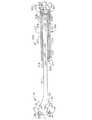
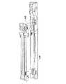
図12〜図16Aは、器具の別の実施の形態を示していて、この実施の形態では、駆動部材500が、上述されたシリンダーアセンブリ501と、以下に記載される相違以外は、構造が同様の、シリンダーアセンブリ800を有する。例えば、この実施の形態では、ばね850、852が、ピストンバー35を後退させるために用いられている。図12および図13に見られるように、シリンダーアセンブリ800は第1のハウジング810を含み、第1のハウジング810は、第1の閉じた端部812および第1のハウジング810を通る第1の供給ポート813を有する。第1の供給ライン840は、第1の閉じた端部812に取り付けられていて、加圧ガスを第1の供給ポート813を通して供給する。この実施の形態では、第1のシリンダーハウジング810は、上述したさまざまな実施の形態に関して記載された第2の開口529を欠いている。第2のシリンダーハウジング820は、第1のシリンダーハウジング810内にスライド可能に受容され、第2の閉じた近位の端部822を有し、この端部822には第1のピストンヘッド828が形成されている。第1のシリンダー領域815が、第1の閉じた端部812と第1のピストンヘッド828との間に画定されている。第1の後退ばね850が、第1のピストンヘッド828と、第1のシリンダーハウジング810の遠位の端部に形成された第1のフランジ817との間に設けられている。第1の後退ばね850は、図12に示すように、第2のシリンダーハウジング820を、第1のシリンダー810内の後退位置に付勢するのに役立つ。ピストンバー35は、段付き端部35’を有し、その段付き端部35’は、第2のシリンダーハウジング820の第2の遠位の端部824に入るような寸法を有する。第2のフランジ825は、第2の遠位の端部824に形成されていて、実質的に横方向に動く密閉をピストンバー35の段付き部分35’との間で達成する。第2のピストンヘッド830が、段付きピストンバー部分35’の近位の端部に設けられていて、第2のピストンヘッド830と第1のピストンヘッド828との間に第3のシリンダー領域832を画定している。第1の開口827が、第1のピストンヘッド828を通して設けられていて、空気が第1のシリンダー領域815と第3のシリンダー領域832との間を通過できるようにしている。第2の後退ばね852が、第2のフランジ825と第2のピストンヘッド830との間に、図12に示すように、設けられていて、第2のピストンヘッド830および段付きピストンバー35’を図12に示されているような第2のシリンダーハウジング820内の完全な後退位置へ付勢している。 FIGS. 12-16A illustrate another embodiment of the instrument in which the
本発明のこの実施の形態は、以下のように、操作される場合がある。図16に見られるように、ハンドルアセンブリ300には、上述されたような加圧ガスの交換可能な供給源620が設けられている。しかし、当業者は、加圧ガスの交換不可能な供給源(シリンダー)も、有効に用いられる場合があることを、理解するであろう。さらに、他の実施の形態では、ハンドルアセンブリ300には、方向制御弁610および関連するコンポーネントを外部の加圧ガスの供給源618に取り付けるのを容易にするためのポート616が設けられている。図16Aを参照のこと。例えば、器具10は、柔軟な供給ライン617を介して施設の加圧空気ラインに連結できる。 This embodiment of the invention may be operated as follows. As seen in FIG. 16, the
器具を操作するために、臨床医は、方向制御弁セレクタースイッチ612(図1)またはプッシュボタンを、前進(伸長)位置に移し、作動トリガ670を引き始め、加圧ガスがシリンダー622(または外部の供給源618)から供給ライン680を通り、方向制御弁610を通り、そして、供給ライン840へ、流れることができるようにする。加圧ガスは、第1の供給ライン840から、第1の供給ポート813を通り、第1のシリンダー領域815内に流れ、第1の開口827を通って、第3のシリンダー領域832内に流れる。第3のシリンダー領域832に入るガスは、第2のピストンヘッド830およびピストンバー35の段付き部分35’を遠位の向きに動くようにする。第2のピストンヘッド830が完全な伸長位置(図13)に移動し終えた後に、第1のシリンダー領域815に入り続けるガスは、第2のハウジング820をその完全な伸長位置へ付勢する。一旦ナイフアセンブリ30がエンドエフェクター12内のその最も遠位の位置に進み終えると、臨床医は、作動トリガ670を解放して、加圧ガスを加えることを中止する。 To operate the instrument, the clinician moves the directional control valve selector switch 612 (FIG. 1) or push button to the advanced (extended) position and begins to pull the
発射機構またはナイフアセンブリ30を後退させるために、臨床医30は方向弁セレクタースイッチ612を逆転(後退)位置に移し、この逆転位置では、第1の供給ライン840が方向弁610の通気口に接続される。第3のシリンダー領域832および第1のシリンダー領域815内のガスは、第1の供給ポート813を通って出て、供給ライン840に入り、そして、最終的に、方向弁610を通って排気される。ガスが第3のシリンダー領域832を出ると、第2の後退ばね852は、ピストンバー35の段付き部分35’を第2のシリンダーハウジング820内に後退させる。同様に、ガスが第1のシリンダー領域815を出ると、第1の後退ばね850は、第2のシリンダーハウジング520を第1のシリンダーハウジング810内に付勢する。 To retract the firing mechanism or
さらに、この実施の形態では、圧力センサー5413は、表示するために、表示部材549に電子的に連結されている場合がある。圧力センサー5413は、図16および図16Aに示されているように供給ライン840に流体連結されていて、圧力センサー5413は、上述したように機能することができ、エンドエフェクター12のよって経験された力に比例する読取値を臨床医に提供するのに役立つ。他のさまざまな実施の形態では、可聴出口545が、図16Bに示されているように供給ライン840に設けられている場合があり、可聴出口545は、上述されたように機能することができ、駆動システム500によって、そして、最終的に発射機構によって、経験される発射力を監視するための可聴フィードバック機構を臨床医に提供する。他の代わりの実施の形態では、リミットスイッチ546(図15)が、方向スイッチ610を自動的に制御するため、および/または、発射機構が発射ストロークの終点に到達し終えたことを示す視覚的または可聴信号を提供するため、発射ロッド35に埋め込まれた作動部材547(図12および図13)を検出する目的で、遠位の背部分110内に設けられている場合がある。Further, in this embodiment, the
図17から図21Aは、器具のさらに別の実施の形態を示していて、その実施の形態では、駆動機構500は、ベローズアセンブリ900を含む。ベローズアセンブリ900は、ナイフバーアセンブリ30の遠位の部分31に取り付けられた遠位の端部902を有する場合がある。遠位の端部902は、遠位の端部902に形成された突出部904を有し、その突出部904は遠位の部分31の開口33内に受容されるような寸法を有する。突出部904は、開口33内に摩擦を伴って受容され、ならびに/または、接着剤および/もしくは溶接によって開口33内に維持される。遠位の部分31は、これまでに詳しく記載されたように、構築されおよび構成されている場合がある。 FIGS. 17-21A illustrate yet another embodiment of the instrument, in which the
ベローズアセンブリ900は、拡張可能/後退可能なベローズ部分910をさらに含み、ベローズ部分は、図18に示されているように、遠位の背部分のベローズ通路117内で、伸長および後退するような寸法を有する。ベローズ部分910は、図20に示されているようにワイヤ閉じ込めリング(wire containment rings)912を用いて形成されて、基部914に取り付けられている場合があり、基部914は、遠位の背部分110に移動不可能に取り付けられるか、または、遠位の背部分110の一体的な部分を構成している。基部914は、遠位の背部分110に、接着剤および/またはねじによって、取り付けられている場合がある。供給ポート916は、ベローズ基部914を通って、設けられていて、供給ライン940は、供給ポート916に取り付けられている。供給ライン940は、ハンドルアセンブリ300内の方向制御弁610にも連結されている。図21および図21Aを参照のこと。方向制御弁610は、真空ライン922を通して、ハンドルアセンブリ300内に取り付けられた真空ポート620にも連通している。真空ポート620は、例えば、柔軟なライン632によって、真空の供給源630に取り付け可能である。真空の供給源は、施設内の永久的な真空供給ラインである場合がある。柔軟な真空ライン632は、ポート620から真空の供給源630に取り付けられている場合があり、臨床医が器具を自由に操縦できるようにしている。 The
この器具には、上述された閉鎖チューブアセンブリ170および閉鎖トリガ302の構成が設けられている場合がある。したがって、組織は、上述された方式で、エンドエフェクター12に挟まれる場合がある。組織がエンドエフェクター12に挟まれた後に、臨床医は以下のように器具を発射する場合がある。臨床医は、方向制御弁610用のセレクタースイッチ612(図1)またはボタンを前進(伸長)位置に動かして、作動トリガ670を引き始める。作動トリガ670が引かれると、流量弁660は、加圧ガスが圧力供給源620(図21)または618(図21A)から方向制御弁610へ流れることができるようにする。方向制御弁610は、加圧ガスが供給ライン940を通ってベローズ910内に流れ込むようにし、ベローズを遠位の向きに伸長するようにする。ベローズ910が遠位の向きに伸長すると、ベローズはナイフアセンブリ30を、エンドエフェクター12を通すように押し、エンドエフェクター12に挟まれた組織を切断し、ステープルカートリッジ50内のステープルを押し出して、アンビル40の底面と接触させてステープルを形成させる。ナイフアセンブリ30がエンドエフェクター12内のナイフアセンブリの最も遠位の位置に押され終えた後に、臨床医は作動トリガ670を解放する。ナイフアセンブリ30を後退させるために、臨床医は、方向制御弁610用のセレクタースイッチ612を後退位置に移し、それによって、真空の供給源630を供給ライン940に連結させる。供給ライン940に真空を加えることによって、ベローズ910は図18に示されたベローズの後退位置へ後退させられる。ベローズ910が完全に後退させられた後に、臨床医はセレクタースイッチ612またはボタンを、方向制御弁が供給ライン940への真空の供給を停止する位置へ、移す場合がある。しかし、供給ライン940内の残りの真空は、ベローズ910を後退位置に維持するのに役に立つ場合がある。 The instrument may be provided with the
図21に示されている実施の形態では、加圧ガスの取り外し可能な供給源620が用いられている。以下に詳しくさらに記載されるように、そのような加圧ガスの供給源は、再充填可能なシリンダー622を含む場合がある。しかし、当業者は、加圧ガスまたは加圧流体の交換不可能な/再充填不可能な供給源(シリンダー)も、有効に用いられる場合があることを、理解するであろう。さらに、他の実施の形態では、ハンドルアセンブリ300には、加圧ガスの外部供給源に対する、加圧ガスを供給するためのポート616が設けられている場合がある。例えば、器具10は、柔軟な供給ライン617を通って、施設の圧縮空気供給ラインに連結されている場合がある。図21Aを参照のこと。 In the embodiment shown in FIG. 21, a
さらに、この実施の形態では、圧力センサー5413が、図21および図21Aに示されているように供給ライン940に流体連結されている場合があり、圧力センサー5413は上述したように機能し、エンドエフェクターによって経験される力に比例する読取値を臨床医に提供するのに役立つ。他のさまざまな実施の形態では、可聴出口545が、図21Bに示されているように、供給ライン940に設けられている場合があり、可聴出口545は、上述したように機能し、作動システム500によって、そして、最終的には、発射機構によって、経験される発射力を監視するための可聴フィードバック機構を臨床医に提供する。他の代わりの実施の形態では、リミットスイッチ546(図18)は、方向スイッチ610を自動的に制御するために、および/または、発射機構またはナイフアセンブリ30が発射ストロークの終点に到達し終えたことを示す視覚的または可聴信号を提供するために、ベローズアセンブリ900に設けられた作動部材912’(図20)を検出する目的で、遠位の背部分110内に設けられている場合がある。Further, in this embodiment, the
図25は、使用中に一回または複数回、器具の状態を記録する能力を備えた手術用器具のさまざまな実施の形態を示している。図25は、器具10の状態を記録するためのシステム750のブロック図である。システム750は、例えば、上記の実施の形態に関連して記載されたような、空気圧制御された、または、空気圧支援された発射を備えた器具10の実施の形態で実現される場合があることが、理解されるであろう。しかし、実施の形態は、この状況に限定されない。 FIG. 25 illustrates various embodiments of a surgical instrument with the ability to record the condition of the instrument one or more times during use. FIG. 25 is a block diagram of a
システム750は、複数の器具の状態を感知するために、さまざまなセンサー752、754、756、758、760、762、770を含む場合がある。センサーは、例えば、器具10の表面または器具10の中に配されている場合がある。さまざまな実施の形態では、センサーはシステム750に対してのみ出力信号S1からSnを供給する専用センサーである場合があり、または、器具10内で他の機能をも実行する二重用途センサーである場合がある。例えば、上述された、センサー662、720、724、および、論理モジュール726は、システム750にも出力信号を供給するように構成されている場合がある。
直接または間接に、各センサーは、信号S1からSnを、メモリ装置703(図26)および/またはコントローラ702に供給する。メモリ装置703は、以下により詳しく記載するように、信号S1からSnを記録する。メモリ装置703は、センサー信号S1からSnを記憶または記録することが可能な任意の種類の装置である場合がある。例えば、メモリ装置703は、マイクロプロセッサ(例えば、コントローラ702)、電気的消去可能読み出し専用メモリ(EEPROM)、または、任意の他の適切な記憶装置を含む場合がある。メモリ装置703は、センサーによって供給された信号を任意の適切な形で記録する場合がある。例えば、ある実施の形態では、メモリ装置703は、信号が状態を変化させたときに特定のセンサーからのその信号を記録する場合がある。もう一つの実施の形態では、メモリ装置703は、システム750の状態を記録する場合があり、例えば、システム750に含まれるすべてのセンサーからの信号S1からSnを、任意のセンサーからの信号S1からSnが状態を変化させたときに、記録する場合がある。このような記録は、器具10の状態のスナップショットを提供する場合がある。さまざまな実施の形態では、メモリ装置703および/またはセンサーは、例えば、1−WARE EEPROMのような、ダラス・セミコンダクター(DALLAS SEMICONDUCTOR)から入手可能な、1−WAREバス製品を含むように実現される場合がある。Directly or indirectly, each sensor provides signals S1 toSn to memory device 703 (FIG. 26) and / or
さまざまな実施の形態では、メモリ装置703は、外部からアクセス可能であり、コンピュータのような外部装置がメモリ装置703によって記録された器具の状態にアクセスできるようになっている。例えば、メモリ装置703は、データポート764を含む場合がある。データポート764は、例えば、シリアルまたはパラレルフォーマットで、任意の有線または無線式通信プロトコルに基づいて、記憶された器具の状態を提供する場合がある。メモリ装置703は、出力ポート764に加えて、または出力ポート764の代わりに、取り外し可能な媒体766をも含んでいる場合がある。取り外し可能な媒体766は、器具10から取り外すことができる任意の種類の適切なデータ記憶装置である場合がある。例えば、取り外し可能な媒体766は、パーソナル・コンピュータ・メモリ・カード・インターナショナル・アソシエーション(Personal Computer Memory Card International Association:PCMCIA)カード、コンパクトフラッシュ(COMPACTFLASH)カード、マルチメディア(MULTIMEDIA)カード、および/または、フラッシュメディア(FLASHMEDIA)カードのような、任意の適切な種類のフラッシュメモリを含む場合がある。取り外し可能な媒体766は、例えば、ポータブルハードディスクドライブ、コンパクトディスク(CD)、および/または、デジタルビデオディスク(DVD)を含む任意の適切な種類のディスクベースの記憶装置をも含む場合がある。 In various embodiments, the
図26は、器具の、ある実施の形態を示している。図26に示された実施の形態は、複数のセンサー、および電子制御モジュール603のより詳しい図を示している。図示されているように、電子制御モジュール603は、コントローラ720、メモリ装置703、測定回路732、アクチエータ706、および、バッテリー704を含んでいる。閉鎖トリガセンサー752は、閉鎖トリガ302の状態を感知する。図26に示されているように、閉鎖トリガセンサー752は、閉鎖トリガ302と閉鎖ピボットピン306との間に配されている。閉鎖トリガ302をピストルグリップ342に向けて引くと、閉鎖トリガ302が閉鎖ピボットピン306に力を加えるようになることが、理解されるであろう。センサー752がこの力を感知して、力に反応して信号を出力し、例えば、弁作動センサー662に関してそして図22Aおよび図22Bに関して上述されたように、信号を出力する場合がある。さまざまな実施の形態では、閉鎖トリガセンサー752は、デジタルセンサーである場合があり、そのデジタルセンサーは閉鎖トリガ302が作動させられているか否かのみを示す。別のさまざまな実施の形態では、閉鎖トリガセンサー752は、アナログセンサーである場合があり、そのアナログセンサーは、閉鎖トリガ302に加えられた力、および/または、閉鎖トリガ302の位置を示す。閉鎖トリガセンサー752がアナログセンサーである場合には、アナログ−デジタル変換器がセンサー752とメモリ装置703との間に論理的に配されている場合がある。さらに、閉鎖トリガセンサー752は任意の適切な形態をとる場合があり、閉鎖トリガ302の状態を感知できるようにする任意の適切な位置に配される場合があることが、理解されるであろう。 FIG. 26 illustrates one embodiment of the instrument. The embodiment shown in FIG. 26 shows a more detailed view of the sensors and the
図27は、アンビル閉鎖センサー754の、ある実施の形態を示している。アンビル閉鎖センサー754は、アンビル40が閉じられたか否かを感知する場合がある。センサー754は、図示されているように、細長い導管20のアンビルカムスロット28に隣接して、または、アンビルカムスロット28内に、配されている。アンビル40が閉じられると、アンビルピボット43は、アンビルカムスロット28を通ってスライドして、センサー754と接触するようになり、センサー754が、アンビル40が閉じられたことを示す信号を出力するようにする。センサー754は、近接センサーを含む、任意の適切な種類のデジタルまたはアナログセンサーである場合がある。アンビル閉鎖センサー754がアナログセンサーである場合、アナログ−デジタル変換器がセンサー754とメモリ装置703および/またはコントローラ702との間に論理的に含まれている場合があることが、理解されるであろう。 FIG. 27 illustrates one embodiment of an
アンビル閉鎖負荷センサー756は、細長い導管20の内側底面に配されて図示されている。使用中には、センサー756は、ステープルカートリッジ50(図27に示されていない)の底側と接触する場合がある。アンビル40が閉じられると、アンビル40はステープルカートリッジ50に力を加え、その力がセンサー756に伝えられる。それに反応して、センサー756は信号Snを出力する。信号Snは、ステープルカートリッジ50によって、およびアンビル40の閉鎖に起因して、センサー756に加えられた力に比例するアナログ信号である場合がある。図25を参照すると、アナログ信号は、アナログ−デジタル変換器768に供給されて、信号をメモリ装置703および/またはコントローラ702に供給する前に、アナログ信号をデジタル信号に変換する。センサー756がデジタルすなわち2進センサーである実施の形態がアナログ−デジタル変換器768を含まない場合があることが、理解されるであろう。Anvil
発射トリガセンサー770は、発射トリガ310の位置および/または状態を感知する。加えて、発射トリガセンサー770は、上述された形態のいずれかをとる場合があり、アナログまたはデジタルである場合がある。図26は、発射トリガセンサー770の実施の形態を示している。図26では、発射トリガセンサー770は、発射トリガ310と発射トリガピボットピン370との間に取り付けられている。発射トリガ310が引かれると、発射トリガ310は発射トリガピボットピン370に力を加え、その力がセンサー770によって感知される。図25を参照すると、発射トリガセンサー770の出力がアナログである実施の形態では、アナログ−デジタル変換器772が、発射トリガセンサー770とメモリ装置703および/またはコントローラ702との間に論理的に含まれている。
図28は、ナイフ位置センサー758の、ある実施の形態を示していて、そのナイフ位置センサー758は、ナイフアセンブリ30から突出した空気圧作動ピストンバー部分35と共に用いるのに適している。ナイフ位置センサー758は、細長い導管20内でのナイフアセンブリ30または切断エッジ38の位置を感知する。センサー758は、器具10のピストンバー部分35に連結された磁石774を含む。コイル776がピストンバー部分35の周りに配されている。ナイフアセンブリ30および切断エッジ38が細長い導管20を通って往復運動させられると、ピストンバー部分35および磁石774は、コイル776を通って、前後に動く場合がある。コイルに関連するこのような動きは、コイル内でのピストンバー部分35の位置および細長い導管20内での切断エッジ38の位置に比例する電圧をコイル中に誘起する。この電圧は、例えば、アナログ−デジタル変換器778を介して、メモリ装置703および/またはコントローラ702に供給される場合がある。 FIG. 28 illustrates one embodiment of a
さまざまな実施の形態では、ナイフ位置センサー758は、代わりに、細長いシャフトアセンブリ100の表面、または、シャフトアセンブリ100内のさまざまな位置に配された一連のデジタルセンサー(図示されていない)として実現される場合がある。デジタルセンサーは、例えば、磁石774のようなピストンバー部分35の特徴部を、その特徴部が細長いシャフトアセンブリ100を通って往復運動するときに、感知する場合がある。ピストンバー部分35の細長いシャフトアセンブリ100内での位置、そして、伸長による、ナイフアセンブリ30の位置は、通り越された最後のデジタルセンサーの位置で、近似値を得られる場合がある。 In various embodiments, the
図29および図30は、カートリッジ存在センサー760の、ある実施の形態を示している。カートリッジ存在センサー760は、ステープルカートリッジ40が細長い導管20内に存在することを感知する場合がある。器具10のいくつかの実施の形態では、カートリッジ存在センサー760は、カートリッジロックアウトセンサーとの二役を務める場合がある。カートリッジロックアウトセンサーは、エンドエフェクター12がステープルカートリッジ40を含むか否かに基づいて状態を変化させる。例えば、エンドエフェクター12がステープルカートリッジ40を含むと、ロックアウトセンサーは、閉じた状態にあり、電流が流れることができるようにし、そうではなく、エンドエフェクター12がステープルカートリッジ40を含まないと、ロックアウトセンサーは開いた状態にあって、器具10が作動されるのを防止する。図示された実施の形態では、カートリッジ存在センサー760は、2つの接点780および782を含む。カートリッジ40が存在しないと、接点780、782は開いた回路を形成する。カートリッジ40が存在すると、ステープルカートリッジ40のカートリッジトレイ68が接点780、782と接触し、閉回路が形成される。回路が開いていると、センサー760は、論理0を出力する場合がある。回路が閉じていると、センサー760は、論理1を出力する場合がある。センサー760の出力は、例えば、図24に示されているように、メモリ装置703および/またはコントローラ702に供給される。 29 and 30 illustrate one embodiment of a cartridge presence sensor 760. Cartridge presence sensor 760 may sense that
カートリッジ状態センサー762は、細長い導管20内に据え付けられたカートリッジ40が発射または費やされ終えたか否かを示す場合がある。ナイフアセンブリ30がエンドエフェクター12を通って移動されると、ナイフアセンブリ30がウエッジスレッド64を押し、ウエッジスレッドがステープルカートリッジ40を発射する。次に、ナイフアセンブリ30が、その元々の位置に移動されて戻り、ウエッジスレッド64がカートリッジ40の遠位の端部に残される。ウエッジスレッド64がナイフアセンブリ30をガイドしていない状態で、ナイフアセンブリ30は、細長い導管20内の固定開口21内に落ちる。センサー762は、ナイフアセンブリ30が固定開口21内に存在するか否かを感知する場合があり、このことが、カートリッジ40が費やされ終えたか否かを間接的に示す。さまざまな実施の形態では、センサー762がカートリッジ40の近位の端部にウエッジスレッド64が存在することを直接感知する場合があり、したがって、ナイフアセンブリ30が固定開口21内に落ちる必要をなくすことが、理解されるだろう。
弁作動センサー662は、作動トリガ670に連結されている。弁作動センサー662は、デジタル・オン/オフ・スイッチである場合があり、または、図22Aおよび図22Bを参照して記載されたように、アナログ比例センサーである場合がある。弁作動センサー662の出力は、メモリ装置703および/またはコントローラ702に連結されている。弁作動センサー662が、作動トリガ670の動きを検出すると、センサー662は、作動信号Snをコントローラ702に送り、可変流量空気圧弁660を作動させる。弁作動センサー662がデジタルデジタル・オン/オフ・スイッチである場合、センサー662は、電気信号Snをコントローラ702に送り、可変流量空気圧弁660を作動させる。弁作動センサー662がアナログ比例センサーである場合、センサー662は、作動トリガ670によって弁作動センサー662に加えられた圧力に比例するアナログ信号Snを出力する。比例出力信号Snは、アナログ−デジタル変換器786に供給されて、アナログ信号がメモリ装置703に供給される前に、デジタル信号に変換される。コントローラ702は、可変流量空気圧弁660を調節して、望ましい流量の加圧ガスを、作動トリガによって弁作動センサー662に加えられた圧力に基づいて、前述したように、生じさせる。
図31Aおよび図31Bは、さまざまな実施の形態に基づく、体内カッターとして構成され、器具の状態を記録する能力を有する、手術器具10の実施の形態を操作するための、プロセスフロー2200の、ある実施の形態を示している。ボックス2202では、器具10のアンビル40が、閉じられる場合がある。アンビル40が閉じられることによって、閉鎖トリガセンサー752および/またはアンビル閉鎖センサー756は状態を変化させることになる。それに反応して、メモリ装置703が、ボックス2203で、システム750のセンサーのすべての状態を記録する場合がある。ボックス2204では、器具10は、患者の体内に挿入される場合がある。器具が挿入されると、アンビル10は、例えば、手術部位での組織を扱うために、ボックス2206で開閉される場合がある。アンビル40の開閉ごとに、閉鎖トリガセンサー752および/またはアンビル閉鎖センサー756が、状態を変える。それに反応して、メモリ装置703は、ボックス2205で、システム750の状態を記録する。 FIGS. 31A and 31B are a
ボックス2208では、組織が切断およびステープリングのために挟まれる。アンビル40が判定ブロック2210で閉じられていない場合、引き続き挟むことが必要である。アンビル40が閉じられている場合、次に、センサー752、754および/または756が、状態を変える場合があり、メモリ装置703にボックス2213でシステムの状態を記録するように促す。この記録には、センサー756から受信された閉鎖圧力が含まれる場合がある。ボックス2212では、切断およびステープリングが行われる場合がある。発射トリガセンサー770は、発射トリガ310がピストルグリップ342に向けて引かれたときに、状態を変える場合がある。さらに、ナイフアセンブリ30が細長い導管20を通って移動するとき、ナイフ位置センサー758が状態を変える。それに反応して、メモリ装置703は、ボックス2013で、システム750の状態を記録する場合がある。 In
切断およびステープリング動作が完了したとき、ナイフアセンブリ30は、発射前位置に戻る場合がある。カートリッジ50はいまや発射され終えているので、ナイフアセンブリ30は、固定開口21内に落ちる場合があり、カートリッジ状態センサー762の状態を変化させ、メモリ装置703が、ボックス2015でシステム750の状態を記録するように誘発する。次に、アンビル40が、組織を取り除くために、開かれる場合がある。アンビル40が開かれることは、閉鎖トリガセンサー752、アンビル閉鎖センサー754、および、アンビル閉鎖負荷センサー756のうちの一つまたは複数のセンサーに状態を変えるようにさせ、その結果、ボックス2017でシステム750の状態の記録を行うようにする。組織が、取り除かれた後、アンビル40は、ボックス2220で再び閉じられる場合がある。アンビルの閉鎖は、少なくともセンサー752および754での別の状態変化を起こさせ、その状態変化がこんどはメモリ装置703がボックス2019でシステムの状態を記録するようにする。次に、器具10は、ボックス2222で、患者の体内から取り除かれる場合がある。 When the cutting and stapling operation is complete, the
器具10が同じ手術中に再び用いられるべき場合、アンビル40は、ボックス2224で開かれ、ボックス2223でシステム状態のもう一つの記録が誘発される。費やされたカートリッジ50は、ボックス2226でエンドエフェクター12から取り除かれる場合がある。カートリッジの除去は、カートリッジ存在センサー760に状態を変化させ、ボックス2225でシステム状態の記録を引き起こす。別のカートリッジ50が、ボックス2228で、挿入される場合がある。カートリッジの挿入は、カートリッジ存在センサー760の状態変化を引き起こし、ボックス2227でシステムの状態の記録を引き起こす。別のカートリッジ50が新しいカートリッジの場合、判定ブロック2230で示されているように、その新しいカートリッジの挿入は、カートリッジ状態センサー762の状態変化をも引き起こす。この場合、システムの状態は、ボックス2231で記録される場合がある。 If the
図32は、メモリ装置703からのメモリマップ2300の、ある実施の形態を示している。メモリマップ2300は、一連の列2302、2304、2306、2308、2310、2312、2314、2316、および、行(符号が付されていない)を含む。列2302は、各行の事象番号を示している。他の列は、システム750の一つのセンサーの出力を表している。所定の時間に記録されたセンサーの読取値のすべては、同じ事象番号の下で、同じ行に記録される場合がある。この故に、各行は、システム750のセンサーからの一つまたは複数の信号が記録された事例を表している。 FIG. 32 illustrates one embodiment of a
列2304は、各事象で記録された閉鎖負荷を列挙している。この閉鎖負荷の列挙は、アンビル閉鎖負荷センサー756の出力を反映している。列2306は、発射ストローク位置を列挙している。発射ストローク位置は、ナイフ位置センサー758から導かれる。例えば、ナイフアセンブリ30の全行程は、区画に分割される場合がある。列2306に列挙された番号は、ナイフアセンブリ30が現在存在する区画を表す場合がある。発射負荷が列2308に列挙されている。発射負荷は、発射トリガセンサー770から導かれる場合がある。ナイフ位置が、列2310に列挙されている。ナイフ位置は、発射ストロークと同様にナイフ位置センサー758から導かれる場合がある。アンビル40が開いているか閉じているかが列2312に列挙されている。この値は、アンビル閉鎖センサー754および/またはアンビル閉鎖負荷センサー756の出力から導かれる場合がある。ウエッジスレッド64が存在するか否か、または、カートリッジ50が費やされたか否かは、列2314に示される場合がある。この値は、カートリッジ状態センサー762から導かれる場合がある。最後に、カートリッジ50が存在するか否かが、列2316に示される場合がある。この値は、カートリッジ存在センサー760から導かれる場合がある。例えば、さまざまな他のセンサーによって測定されたような、例えば、発射ストロークの終了および開始などを含む、さまざまなその他の値が、メモリ装置703に記憶される場合があることが、理解されるであろう。
図33は、手術用器具2400のさまざまな実施の形態を示している。手術用器具2400は、上述された手術用器具10と同様である場合があり、しかし、手術用器具2400には取り外し可能に結合された状態モジュール2402をも含む。状態モジュール2402は、図33では、ハンドルアセンブリ300の外側の下側部品に結合されて示されているが、状態モジュール2402が任意の適切な位置で手術用器具2400に結合されている場合があることが、理解されるであろう。さまざまな実施の形態に基づけば、手術用器具2400のハンドルアセンブリ300は、状態モジュール2402を受容するように構成され配置された凹部を画定している。 FIG. 33 illustrates various embodiments of a
図34は、複数のセンサー2404を含む手術用器具2400の、ある実施の形態の模式図を示している。複数のセンサー2404は、例えば、関節角度センサー、アンビル位置センサー、カートリッジセンサー、閉鎖トリガセンサー、閉鎖力センサー、発射力センサー、ナイフ位置センサー、ロックアウト状態センサー、または、それらの任意の組み合わせを含む。各センサー2404は、手術用器具2400の外側の近くに配されたさまざまな接点2406(図34に模式的に示されている)と電気的に通信を行う場合がある。 FIG. 34 shows a schematic diagram of an embodiment of a
センサー2404は、任意の適切な方式で、実現される場合がある。例えば、関節角度センサーは、例えば、電位差計として実現される場合があり、電位差計は、関節制御部200の一部を含み、エンドエフェクター12の相対的な関節角度を示す信号を出力する。アンビル位置センサーは、例えば、上記のアンビル閉鎖センサー754として実現される場合がある。カートリッジセンサーは、例えば、上記のカートリッジ存在センサー760として実現される場合がある。閉鎖トリガセンサーは、例えば、上記の閉鎖トリガセンサー752として実現される場合がある。閉鎖力センサーは、例えば、上記のアンビル閉鎖負荷センサー756として実現される場合がある。発射力センサーは、例えば、上記の発射トリガセンサー770として実現される場合がある。ナイフ位置センサーは、例えば、上記のナイフ位置センサー758として実現される場合がある。ロックアウト状態センサーは、例えば、上記のカートリッジロックアウトセンサーまたはカートリッジ存在センサー760として、実現される場合がある。
さまざまな実施の形態に基づけば、状態モジュール2402は、手術用器具2400に取り外し可能に結合されるように構成され配されたハウジング2408を含んでいる。状態モジュール2408は、複数の接点2410(図34に模式的に示されている)を含み、異なる接点2410の各々は、ハウジング2408が手術用器具2400に結合されたとき、手術用器具2400の異なるセンサー2404と電気的に通信を行うように構成され配されている。例えば、状態モジュール2402が手術用器具2400に結合されると、状態モジュール2402の各接点2410は、手術用器具2400の対応する各接点2406と整合させられる場合があり、それによって、状態モジュール2402の各接点2410を異なるセンサー2404と電気的に通信を行う状態にする。 According to various embodiments, the
状態モジュール2402は、少なくとも一つの接点2410と通信を行う回路2412(図34に模式的に示されている)、および、複数の表示器2414(図34に模式的に示されている)をさらに含む。少なくとも一つの表示器2414は、回路2412と電気的に通信を行う。回路2412は、駆動回路を含み、少なくとも一つの表示器2414を駆動するように構成され配されている。さまざまな実施の形態に基づけば、回路2412は、図34に模式的に示されているように、スイッチ2416、カウンター2418、送信機2420、または、それらの任意の組み合わせをさらに含む場合がある。ある実施の形態では、回路は、電子制御モジュール603に連結されている。 The
スイッチ2416は、少なくとも一つの表示器2414と電気的に通信を行い、スイッチ2416と電気的に通信を行う対応する表示器2414を非作動状態にするために用いられる場合がある。さまざまな実施の形態に基づけば、スイッチ2416は、回路2412以外の状態モジュール2402の一部を含む場合があり、または、状態モジュール2402以外の手術用器具2400の一部を含む場合がある。そのような実施の形態では、スイッチ2416は、回路2412と電気的に通信を行う場合がある。 The
カウンター2418は、発射の回数、残りの発射の回数、および/または、クランプ後の待ち時間を求めるために用いられる場合がある。さまざまな実施の形態に基づけば、カウンター2418は、回路2412以外の状態モジュール2402の一部を含む場合がある。他の実施の形態に基づけば、カウンター2418は、状態モジュール2402以外の手術用器具2400の一部を含む場合がある。そのような実施の形態では、カウンター2418は、回路2412と電気的に通信を行う場合がある。 Counter 2418 may be used to determine the number of firings, the number of remaining firings, and / or the waiting time after clamping. Based on various embodiments, the counter 2418 may include a portion of the
送信機2420は、複数のセンサー2404によって感知された情報を、モニター(図示されていない)に関連する無線式受信機(図示されていない)に、無線式で送信するために用いられる場合があり、そのモニターは、使用者が手術を実行する間に手術用器具2400の使用者によって目視される場合がある。情報は、連続的に、または、周期的に、無線式で送信される場合がある。表示された情報は、例えば、発射進行情報、圧縮負荷情報、ナイフ負荷情報、発射回数、手術時間、圧縮待ち時間、および/または、バッテリーレベルなどを含む場合がある。他のさまざまな実施の形態に基づけば、送信機2420は、回路2412以外の状態モジュール2402の一部を含む場合があり、または、状態モジュール2402以外の手術用器具2400の一部を含む場合がある。そのような実施の形態では、送信機2420は、回路2412と電気的に通信を行う場合がある。 Transmitter 2420 may be used to wirelessly transmit information sensed by
図35〜図37は、状態モジュール2402のさまざまな実施の形態を示している。図示されているように、状態モジュール2402は、さまざまな種類の表示器2414を含む場合がある。さまざまな実施の形態に基づけば、表示器2414は、例えば、発光ダイオード、多色発光ダイオード、および/もしくは、ディスプレイ、または、それらの任意の組み合わせのような、一つまたは複数の視覚的表示器を含む場合がある。ディスプレイは、例えば、英数字ディスプレイ、ドットマトリクスディスプレイ、および/または、液晶ディスプレイを含む場合がある。さまざまな実施の形態に基づけば、少なくとも一つの表示器2414は、例えば、音響出力装置のような可聴表示器を含む場合がある。可聴出力装置は、例えば、スピーカーとして実現される場合があり、スイッチ2416と電気的に通信を行う場合がある。さまざまな実施の形態に基づけば、表示器2414は、少なくとも一つの視覚的表示器、および、少なくとも一つの可聴表示器を有する場合がある。 FIGS. 35-37 illustrate various embodiments of the
図35は、可聴および視覚的フィードバックを供給する表示器のある実施の形態を示している。動作中に、表示器2414は、手術用器具2400の使用者に視覚的および可聴フィードバックを供給する場合がある。例えば、図35に示されているように、表示器2414(例えば、発光ダイオード)は、閉鎖トリガ302が固定位置にあるか否か、予め決められたクランピング後の待ち時間が完了し終えたか否か、および/または、ステープルカートリッジ50が装填されているか否かを示すために用いられる場合がある。さまざまな表示器2414が、さまざまな色の光を放射する場合がある。図35および図36で用いられる場合、異なるハッチングは異なる色を示している。表示器2414(例えば、多色発光ダイオード)が、手術用器具2400の特定の機能の複数の状態表示に対して用いられる場合がある。例えば、ステープルカートリッジ50の状態を示すために、多色発光ダイオードは、装填されたステープルカートリッジ50が細長い導管20内にある場合に緑色の光を放射し、費やされたステープルカートリッジ50が細長い導管20内にある場合に黄色の光を放射し、ステープルカートリッジ50が導管20内にない場合に赤色の光を放射する場合がある。同様に、切断力が手術用器具2400によって加えられている状態を示すために、多色発光ダイオードは、切断力が正常な範囲内で加えられている場合に緑色の光を放射し、切断力が高い範囲内で加えられている場合に黄色の光を放射し、切断力が高負荷範囲で加えられている場合に赤色の光を放射する場合がある。表示器2414が、例えば、バッテリーレベルのような、手術用器具2400の他の機能の複数の状態表示のために用いられる場合があることが理解される。 FIG. 35 illustrates one embodiment of a display that provides audible and visual feedback. In operation, the
図35に示されているように、表示器2414(例えば、発光ダイオード)の列が、ナイフアセンブリ30の前進、加えられている最大閉鎖力の百分率、加えられている最大発射力の百分率、または、エンドエフェクター12の現在の関節角度を示すために用いられる場合がある。そのような表示は、手術用器具の使用者に、手術用器具2400の操作に関連する力に関するフィードバック、および、手術用器具2400がその最大能力のどれ位近くで動作しているかに関するフィードバックを提供する場合がある。一列の表示器2414のみが図35に示されているが、状態モジュール2402が任意の個数の列の表示器2414を含む場合があることが、理解される。 As shown in FIG. 35, the row of indicators 2414 (e.g., light emitting diodes) may be moved forward of the
図36は、状態モジュールの、ある実施の形態を示している。図36に示されているように、状態モジュール2402は、2つの円形の配向で配列された表示器2414(例えば、発光ダイオード)を含む場合がある。そのような実施の形態では、状態モジュール2402は、図35に示された状態モジュール2402に比べて、より多くの同時発生的情報を手術用器具の使用者に提供することができる場合がある。2つの円形の配列の表示器が図36に示されているが、状態モジュール2402は、任意の複数の配向に配列された任意の複数の表示器2414を含む場合があることが理解される。例えば、状態モジュール2402は、ピラミッド形に配列された表示器を含む場合がある。 FIG. 36 illustrates one embodiment of a status module. As shown in FIG. 36, the
図37は、状態モジュールの、ある実施の形態を示している。図37に示されているように、状態モジュール2402の表示器2414は、一列の発光ダイオード、および、少なくとも一つのディスプレイ(例えば、液晶ディスプレイ)を有する場合がある。そのような実施の形態では、状態モジュール2402は、図35または図36に示された状態モジュール2402に比べて、より多くの同時発生的な情報を手術用器具の使用者に提供できる場合がある。例えば、発光ダイオードは、棒グラフの形式で、アンビル40およびステープルカートリッジ50での反力、バッテリーレベル、または、関節角度を示す場合がある。ディスプレイは、デジタル形式で、閉鎖力、発射力、残りの発射回数、クランピング後の待ち時間、ストロークの進行、または、関節角度に関する情報を示す場合がある。 FIG. 37 illustrates one embodiment of a status module. As shown in FIG. 37, the
器具10のいくつかの実施の形態が記載されたが、それらの実施の形態に対するさまざまな変更、変形、および、適合が、本発明のいくつかのまたはすべての利益を達成して、当業者には思いつく場合があることが、明らかであるはずである。例えば、さまざまな実施の形態に基づけば、所定の一つまたは複数の機能を実行するために、一つのコンポーネントが複数のコンポーネントに置き換えられる場合があり、また、複数のコンポーネントが単一のコンポーネントに置き換えられる場合がある。本出願は、添付の特許請求の範囲によって定義された、開示された手術用器具10の実施の形態の範囲から逸脱せずに、そのようなすべての変形、変更、および、適合を包含することが意図されている。 Although several embodiments of the
本明細書に開示された装置は、一回の使用後に廃棄されるように設計されることができ、または、複数回使用されるように設計されることもできる。しかし、いずれの場合でも、装置は少なくとも一回の使用後に再使用するために再調整することができる。再調整には、装置の分解のステップ、その後の特定の部品の洗浄または交換のステップ、および、その後の再組み立てのステップの組み合わせが含まれる場合がある。より詳しく言うと、装置が分解されることが可能で、装置の任意の個数の特定のピースまたは部品が任意の組み合わせで選択的に交換または除去され得る。特定の部品の洗浄および/または交換の場合には、装置は次の使用のために、再調整施設で、または、手術の直前に手術チームによって、再び組み立てられる場合がある。当業者は、装置の再調整が、分解、洗浄/交換、および、再組み立てのためのさまざまな異なる技術を用いる場合があることを、理解するであろう。そのような技術の使用、および、その結果の再調整された装置はすべて、本出願の範囲内に包含される。 The devices disclosed herein can be designed to be discarded after a single use, or they can be designed to be used multiple times. In either case, however, the device can be reconditioned for reuse after at least one use. Reconditioning may include a combination of equipment disassembly steps, subsequent cleaning or replacement steps for certain parts, and subsequent reassembly steps. More specifically, the device can be disassembled and any number of the particular pieces or parts of the device can be selectively replaced or removed in any combination. In the case of cleaning and / or replacement of particular parts, the device may be reassembled for subsequent use either at a reconditioning facility or by a surgical team immediately prior to surgery. One skilled in the art will appreciate that reconditioning of the device may use a variety of different techniques for disassembly, cleaning / replacement, and reassembly. The use of such techniques and the resulting reconditioned device are all encompassed within the scope of this application.
好ましくは、本明細書に記載された発明は、手術前に処理されるであろう。最初に、新たなまたは使用された器具が、得られ、必要な場合、洗浄される。次に、器具は、滅菌される場合がある。ある滅菌方法では、器具が、プラスチックまたはTYVEK(登録商標)製のバッグのような閉じた密閉された容器内に置かれる。次に、容器および器具が、ガンマ線、X線、または、より高エネルギーの電子のような、容器を透過できる放射線の場の中に置かれる。その放射線は、器具の表面および容器の中の細菌を殺す。次に、滅菌された器具が、滅菌容器内で保管される。密閉された容器は、容器が医療施設内で開けられるまで、器具を滅菌状態に保つ。 Preferably, the invention described herein will be processed before surgery. Initially, new or used equipment is obtained and, if necessary, cleaned. The instrument may then be sterilized. In one sterilization method, the instrument is placed in a closed and sealed container, such as a plastic or TYVEK® bag. The container and instrument are then placed in a field of radiation that can penetrate the container, such as gamma rays, x-rays, or higher energy electrons. The radiation kills bacteria on the instrument surface and in the container. The sterilized instrument is then stored in a sterile container. The sealed container keeps the instrument sterile until the container is opened in the medical facility.
全体または一部が、参照することによって本明細書に組み込まれることが記載された特許、刊行物、または、その他の開示資料は、組み込まれた資料が、本明細書に記載された既存の定義、記述、または、その他の開示資料に抵触しない限りにおいてのみ、本明細書に組み込まれる。よって、必要な限りにおいて、本明細書に明示的に記載された開示内容は、参照することによって本明細書に組み込まれたいずれの抵触する資料にも取って代わる。参照することによって本明細書に組み込まれることが記載され、しかしながら本明細書に記載された既存の定義、記述、またはその他の開示資料と抵触する、任意の資料、または、資料の一部は、それらの組み込まれた資料と既存の開示された資料との間に抵触が生じない限りにおいてのみ、組み込まれるであろう。 Patents, publications, or other disclosure materials that are described in whole or in part by reference are incorporated by reference into the existing definitions set forth herein. , Only as long as it does not conflict with the description or other disclosure material. Thus, to the extent necessary, the disclosure explicitly described herein will supersede any conflicting material incorporated herein by reference. Any document or portion of a document that is incorporated by reference herein, but that conflicts with existing definitions, descriptions, or other disclosure materials described herein, It will be incorporated only to the extent that there is no conflict between those incorporated material and the existing disclosed material.
保護されることが意図される本発明は、開示された具体的な実施の形態に限定されると解釈されない。したがって、実施の形態は、限定的ではなく例示的なものであるとみなされる。変形および変更が、本発明の精神を逸脱せずに他者によって行われるかもしれない。したがって、特許請求の範囲で定義された本発明の精神および範囲内に含まれる、そのような等価物、変形、および、変更のすべてが、特許請求の範囲に包含されることが、明示的に意図される。 The present invention intended to be protected is not to be construed as limited to the specific embodiments disclosed. Accordingly, the embodiments are considered to be illustrative rather than limiting. Variations and changes may be made by others without departing from the spirit of the invention. Therefore, it is expressly intended that all such equivalents, modifications and variations that fall within the spirit and scope of the present invention as defined by the claims are to be embraced by the claims. Intended.
〔実施の態様〕
(1)手術用器具において、
エンドエフェクターであって、前記エンドエフェクター内に配された物体を切断するための移動可能な切断器具を有する、エンドエフェクターと、
前記エンドエフェクターに連結された空気圧作動式の駆動部材と、
前記空気圧作動式の駆動部材に連結された電気制御される可変流量空気圧弁と、
前記電気制御される可変流量空気圧弁を通る流量を制御するために、前記電気制御される可変流量空気圧弁に連結された電子制御モジュールと、
を具備する、手術用器具。
(2)実施態様(1)に記載の手術用器具において、
前記電気制御される可変流量空気圧弁を通る前記流量を調節するための閉鎖機構と、
前記閉鎖機構を制御するためのアクチエータと、
を具備する、手術用器具。
(3)実施態様(2)に記載の手術用器具において、
少なくとも一つのセンサーからフィードバック信号を受信するための測定回路と、
前記測定回路および前記アクチエータに連結されたコントローラであって、前記測定回路は、前記電気制御される可変流量空気圧弁を通る流量に比例するフィードバック信号を前記コントローラに供給する、コントローラと、
を具備する、手術用器具。
(4)実施態様(1)に記載の手術用器具において、
作動トリガであって、前記作動トリガは、前記作動トリガの後退が、前記電気制御される可変流量空気圧弁を作動させ、かつ、前記空気圧作動式の駆動部材を作動させるように構成されており、前記作動トリガの回転位置が、前記エンドエフェクター内での前記切断器具の位置に関連している、作動トリガ、
を具備する、手術用器具。
(5)実施態様(4)に記載の手術用器具において、
前記作動トリガとは別個の閉鎖トリガであって、前記閉鎖トリガの後退は、前記エンドエフェクターが前記エンドエフェクターに配された前記物体を挟むようにさせる、閉鎖トリガ、
を具備する、手術用器具。
(6)実施態様(4)に記載の手術用器具において、
前記作動トリガに連結された弁作動センサーであって、前記弁作動センサーは、前記作動トリガが後退させられたときに、前記電気制御される可変流量空気圧弁を通る望ましい流量に比例する電気信号を、前記電子制御モジュールに供給する、弁作動センサー、
を具備する、手術用器具。
(7)実施態様(6)に記載の手術用器具において、
前記弁作動センサーは、
前記作動トリガに加えられた後退力に比例する電気信号を供給するための比例スイッチを含む、手術用器具。
(8)実施態様(1)に記載の手術用器具において、
前記電子制御モジュールに連結された方向制御弁と、
前記電子制御モジュールに連結された、前記エンドエフェクターの遠位の位置を検出するための、ストローク終了センサーと、
前記電子制御モジュールに連結された、前記エンドエフェクターの近位の位置を検出するための、ストローク開始センサーと、
を具備し、
前記電子制御モジュールが、前記ストローク終了センサーおよび前記ストローク開始センサーの状態に基づいて、前記方向制御弁に、適切な制御信号を供給する、手術用器具。
(9)実施態様(1)に記載の手術用器具において、
閉鎖トリガであって、前記閉鎖トリガの後退は、前記エンドエフェクターが前記エンドエフェクター内に配された物体を挟むようにさせる、閉鎖トリガ、
を具備する、手術用器具。
(10)実施態様(1)に記載の手術用器具において、
前記エンドエフェクターは、
前記切断器具を通すための細長い導管と、
前記細長い導管に旋回可能に結合されたクランピング部材と、
を含む、手術用器具。Embodiment
(1) In surgical instruments,
An end effector comprising a movable cutting instrument for cutting an object disposed in the end effector;
A pneumatically actuated drive member coupled to the end effector;
An electrically controlled variable flow rate pneumatic valve coupled to the pneumatically actuated drive member;
An electronic control module coupled to the electrically controlled variable flow pneumatic valve to control the flow rate through the electrically controlled variable flow pneumatic valve;
A surgical instrument comprising:
(2) In the surgical instrument according to the embodiment (1),
A closure mechanism for adjusting the flow rate through the electrically controlled variable flow pneumatic valve;
An actuator for controlling the closure mechanism;
A surgical instrument comprising:
(3) In the surgical instrument according to the embodiment (2),
A measurement circuit for receiving a feedback signal from at least one sensor;
A controller coupled to the measurement circuit and the actuator, wherein the measurement circuit supplies a feedback signal to the controller proportional to the flow rate through the electrically controlled variable flow pneumatic valve;
A surgical instrument comprising:
(4) In the surgical instrument described in the embodiment (1),
An actuation trigger, wherein the actuation trigger is configured such that retraction of the actuation trigger actuates the electrically controlled variable flow pneumatic valve and actuates the pneumatically actuated drive member; An actuation trigger, wherein a rotational position of the actuation trigger is related to a position of the cutting instrument within the end effector;
A surgical instrument comprising:
(5) In the surgical instrument described in the embodiment (4),
A closure trigger separate from the actuation trigger, wherein retraction of the closure trigger causes the end effector to pinch the object disposed on the end effector;
A surgical instrument comprising:
(6) In the surgical instrument described in the embodiment (4),
A valve actuation sensor coupled to the actuation trigger, the valve actuation sensor providing an electrical signal proportional to a desired flow rate through the electrically controlled variable flow pneumatic valve when the actuation trigger is retracted. A valve actuation sensor for supplying to the electronic control module;
A surgical instrument comprising:
(7) In the surgical instrument described in the embodiment (6),
The valve actuation sensor is
A surgical instrument including a proportional switch for providing an electrical signal proportional to the retracting force applied to the actuation trigger.
(8) In the surgical instrument described in the embodiment (1),
A directional control valve coupled to the electronic control module;
A stroke end sensor coupled to the electronic control module for detecting a distal position of the end effector;
A stroke start sensor coupled to the electronic control module for detecting a proximal position of the end effector;
Comprising
The surgical instrument, wherein the electronic control module supplies an appropriate control signal to the directional control valve based on the state of the stroke end sensor and the stroke start sensor.
(9) In the surgical instrument described in the embodiment (1),
A closure trigger, wherein retraction of the closure trigger causes the end effector to pinch an object disposed within the end effector;
A surgical instrument comprising:
(10) In the surgical instrument according to the embodiment (1),
The end effector is
An elongate conduit for passing the cutting instrument;
A clamping member pivotally coupled to the elongated conduit;
Surgical instruments, including
(11)実施態様(10)に記載の手術用器具において、
前記細長い導管内でのカートリッジの存在を検出するための少なくとも一つのセンサー、
を具備する、手術用器具。
(12)実施態様(10)に記載の手術用器具において、
前記細長い導管内でのカートリッジの状態を検出するための少なくとも一つのセンサー、
を具備する、手術用器具。
(13)実施態様(10)に記載の手術用器具において、
前記クランピング部材の状態を検出するための少なくとも一つのセンサー、
を具備する、手術用器具。
(14)実施態様(10)に記載の手術用器具において、
前記クランピング部材によって加えられた負荷を検出するための少なくとも一つのセンサー、
を具備する、手術用器具。
(15)実施態様(10)に記載の手術用器具において、
前記移動可能な切断器具の位置を検出するための少なくとも一つのセンサー、
を具備する、手術用器具。
(16)方法において、
実施態様(1)に記載の手術用器具を得ることを含む方法であって、
前記手術用器具を滅菌することと、
滅菌容器内に前記手術用器具を保管することと、
を含む、方法。
(17)手術用器具において、
エンドエフェクターと、
前記エンドエフェクターに連結された空気圧作動式の駆動部材と、
前記空気作動式の駆動部材に連結された電気制御される可変流量空気圧弁と、
前記電気制御される可変流量空気圧弁を通る流量を制御するために、前記電気制御される可変流量空気圧弁に連結された、電子制御モジュールと、
前記エンドエフェクターと連通したトリガと、
前記トリガおよび前記エンドエフェクターから成る群の少なくとも一つの要素の第1の状態を表す出力を有する第1のセンサーと、
前記第1のセンサーと通信を行う、外部からアクセス可能なメモリ装置であって、前記メモリ装置は、前記第1のセンサーの前記出力を記録するように構成されている、メモリ装置と、
を具備する、手術用器具。
(18)実施態様(17)に記載の手術用器具において、
前記メモリ装置と通信を行う第2のセンサーであって、前記第2のセンサーは、前記トリガおよび前記エンドエフェクターから成る群の少なくとも一つの要素の第2の状態を表す出力を有し、前記メモリ装置は、前記第2のセンサーの前記出力を記録するようにさらに構成されている、第2のセンサー、
を具備する、手術用器具。
(19)実施態様(18)に記載の手術用器具において、
前記メモリ装置は、前記第1の状態が変化したときに前記第1のセンサーの前記出力を記録し、かつ、前記第2の状態が変化したときに前記第2のセンサーの前記出力を記録するように構成されている、手術用器具。
(20)実施態様(17)に記載の手術用器具において、
前記エンドエフェクターは、旋回式に移動可能なクランピング部材を含み、
前記第1の状態は、前記クランピング部材が開いた位置にあるか、または閉じた位置にあるかを示す、手術用器具。(11) In the surgical instrument according to the embodiment (10),
At least one sensor for detecting the presence of a cartridge in the elongated conduit;
A surgical instrument comprising:
(12) In the surgical instrument described in the embodiment (10),
At least one sensor for detecting a condition of the cartridge within the elongated conduit;
A surgical instrument comprising:
(13) In the surgical instrument described in the embodiment (10),
At least one sensor for detecting a state of the clamping member;
A surgical instrument comprising:
(14) In the surgical instrument according to embodiment (10),
At least one sensor for detecting a load applied by the clamping member;
A surgical instrument comprising:
(15) In the surgical instrument according to the embodiment (10),
At least one sensor for detecting the position of the movable cutting instrument;
A surgical instrument comprising:
(16) In the method,
A method comprising obtaining the surgical instrument according to embodiment (1), comprising:
Sterilizing the surgical instrument;
Storing the surgical instrument in a sterile container;
Including a method.
(17) In surgical instruments,
An end effector,
A pneumatically actuated drive member coupled to the end effector;
An electrically controlled variable flow rate pneumatic valve coupled to the pneumatically actuated drive member;
An electronic control module coupled to the electrically controlled variable flow pneumatic valve to control the flow rate through the electrically controlled variable flow pneumatic valve;
A trigger in communication with the end effector;
A first sensor having an output representative of a first state of at least one element of the group consisting of the trigger and the end effector;
An externally accessible memory device that communicates with the first sensor, wherein the memory device is configured to record the output of the first sensor;
A surgical instrument comprising:
(18) In the surgical instrument according to embodiment (17),
A second sensor in communication with the memory device, the second sensor having an output representative of a second state of at least one element of the group consisting of the trigger and the end effector; A device further configured to record the output of the second sensor, a second sensor;
A surgical instrument comprising:
(19) In the surgical instrument described in the embodiment (18),
The memory device records the output of the first sensor when the first state changes, and records the output of the second sensor when the second state changes. A surgical instrument configured as described above.
(20) In the surgical instrument described in the embodiment (17),
The end effector includes a pivoting movable clamping member,
The surgical instrument, wherein the first condition indicates whether the clamping member is in an open position or a closed position.
(21)実施態様(17)に記載の手術用器具において、
前記第1の状態は、前記エンドエフェクター内での移動可能な切断ナイフ器具の位置、前記トリガの位置、前記トリガに加えられる圧力、および、前記エンドエフェクターによって加えられる圧力のうちのいずれか一つを示す、手術用器具。
(22)手術用器具の状態を記録する方法において、
前記方法は、
少なくとも一つのセンサーの出力を監視することであって、前記出力は、前記手術用器具の状態を表す、監視と、
前記手術用器具の前記状態の少なくとも一つが変化したときに、前記少なくとも一つのセンサーの前記出力をメモリ装置へ記録することと、
を含む、方法。
(23)実施態様(22)に記載の方法において、
前記少なくとも一つのセンサーの記録された前記出力を外部装置に供給すること、
を含む、方法。
(24)実施態様(22)に記載の方法において、
前記少なくとも一つのセンサーの前記出力を前記メモリ装置の出力ポートに供給すること、および
前記少なくとも一つのセンサーの前記出力を取り外し可能な記憶媒体に供給することのうちの少なくとも一つ
を含む、方法。(21) In the surgical instrument according to embodiment (17),
The first state is any one of a position of a movable cutting knife instrument within the end effector, a position of the trigger, a pressure applied to the trigger, and a pressure applied by the end effector. Showing surgical instruments.
(22) In a method of recording the state of a surgical instrument,
The method
Monitoring the output of at least one sensor, wherein the output represents the status of the surgical instrument;
Recording the output of the at least one sensor in a memory device when at least one of the states of the surgical instrument changes;
Including a method.
(23) In the method according to embodiment (22),
Supplying the recorded output of the at least one sensor to an external device;
Including a method.
(24) In the method according to embodiment (22),
A method comprising: providing the output of the at least one sensor to an output port of the memory device; and providing the output of the at least one sensor to a removable storage medium.
Claims (10)
Translated fromJapaneseエンドエフェクターであって、前記エンドエフェクター内に配された物体を切断するための移動可能な切断器具を有する、エンドエフェクターと、
前記エンドエフェクターに連結された空気圧作動式の駆動部材と、
前記空気圧作動式の駆動部材に連結された電気制御される可変流量空気圧弁と、
前記電気制御される可変流量空気圧弁を通る流量を制御するために、前記電気制御される可変流量空気圧弁に連結された電子制御モジュールと、
を具備する、手術用器具。In surgical instruments,
An end effector comprising a movable cutting instrument for cutting an object disposed in the end effector;
A pneumatically actuated drive member coupled to the end effector;
An electrically controlled variable flow rate pneumatic valve coupled to the pneumatically actuated drive member;
An electronic control module coupled to the electrically controlled variable flow pneumatic valve to control the flow rate through the electrically controlled variable flow pneumatic valve;
A surgical instrument comprising:
前記電気制御される可変流量空気圧弁を通る前記流量を調節するための閉鎖機構と、
前記閉鎖機構を制御するためのアクチエータと、
を具備する、手術用器具。The surgical instrument according to claim 1,
A closure mechanism for adjusting the flow rate through the electrically controlled variable flow pneumatic valve;
An actuator for controlling the closure mechanism;
A surgical instrument comprising:
少なくとも一つのセンサーからフィードバック信号を受信するための測定回路と、
前記測定回路および前記アクチエータに連結されたコントローラであって、前記測定回路は、前記電気制御される可変流量空気圧弁を通る流量に比例するフィードバック信号を前記コントローラに供給する、コントローラと、
を具備する、手術用器具。The surgical instrument according to claim 2,
A measurement circuit for receiving a feedback signal from at least one sensor;
A controller coupled to the measurement circuit and the actuator, wherein the measurement circuit supplies a feedback signal to the controller proportional to the flow rate through the electrically controlled variable flow pneumatic valve;
A surgical instrument comprising:
作動トリガであって、前記作動トリガは、前記作動トリガの後退が、前記電気制御される可変流量空気圧弁を作動させ、かつ、前記空気圧作動式の駆動部材を作動させるように構成されており、前記作動トリガの回転位置が、前記エンドエフェクター内での前記切断器具の位置に関連している、作動トリガ、
を具備する、手術用器具。The surgical instrument according to claim 1,
An actuation trigger, wherein the actuation trigger is configured such that retraction of the actuation trigger actuates the electrically controlled variable flow pneumatic valve and actuates the pneumatically actuated drive member; An actuation trigger, wherein a rotational position of the actuation trigger is related to a position of the cutting instrument within the end effector;
A surgical instrument comprising:
前記作動トリガとは別個の閉鎖トリガであって、前記閉鎖トリガの後退は、前記エンドエフェクターが前記エンドエフェクターに配された前記物体を挟むようにさせる、閉鎖トリガ、
を具備する、手術用器具。The surgical instrument according to claim 4, wherein
A closure trigger separate from the actuation trigger, wherein retraction of the closure trigger causes the end effector to pinch the object disposed on the end effector;
A surgical instrument comprising:
前記作動トリガに連結された弁作動センサーであって、前記弁作動センサーは、前記作動トリガが後退させられたときに、前記電気制御される可変流量空気圧弁を通る望ましい流量に比例する電気信号を、前記電子制御モジュールに供給する、弁作動センサー、
を具備する、手術用器具。The surgical instrument according to claim 4, wherein
A valve actuation sensor coupled to the actuation trigger, the valve actuation sensor providing an electrical signal proportional to a desired flow rate through the electrically controlled variable flow pneumatic valve when the actuation trigger is retracted. A valve actuation sensor for supplying to the electronic control module;
A surgical instrument comprising:
前記弁作動センサーは、
前記作動トリガに加えられた後退力に比例する電気信号を供給するための比例スイッチを含む、手術用器具。The surgical instrument according to claim 6, wherein
The valve actuation sensor is
A surgical instrument including a proportional switch for providing an electrical signal proportional to the retracting force applied to the actuation trigger.
前記電子制御モジュールに連結された方向制御弁と、
前記電子制御モジュールに連結された、前記エンドエフェクターの遠位の位置を検出するための、ストローク終了センサーと、
前記電子制御モジュールに連結された、前記エンドエフェクターの近位の位置を検出するための、ストローク開始センサーと、
を具備し、
前記電子制御モジュールが、前記ストローク終了センサーおよび前記ストローク開始センサーの状態に基づいて、前記方向制御弁に、適切な制御信号を供給する、手術用器具。The surgical instrument according to claim 1,
A directional control valve coupled to the electronic control module;
A stroke end sensor coupled to the electronic control module for detecting a distal position of the end effector;
A stroke start sensor coupled to the electronic control module for detecting a proximal position of the end effector;
Comprising
The surgical instrument, wherein the electronic control module supplies an appropriate control signal to the directional control valve based on the state of the stroke end sensor and the stroke start sensor.
閉鎖トリガであって、前記閉鎖トリガの後退は、前記エンドエフェクターが前記エンドエフェクター内に配された物体を挟むようにさせる、閉鎖トリガ、
を具備する、手術用器具。The surgical instrument according to claim 1,
A closure trigger, wherein retraction of the closure trigger causes the end effector to pinch an object disposed within the end effector;
A surgical instrument comprising:
前記エンドエフェクターは、
前記切断器具を通すための細長い導管と、
前記細長い導管に旋回可能に結合されたクランピング部材と、
を含む、手術用器具。The surgical instrument according to claim 1,
The end effector is
An elongate conduit for passing the cutting instrument;
A clamping member pivotally coupled to the elongated conduit;
Surgical instruments, including
Applications Claiming Priority (2)
| Application Number | Priority Date | Filing Date | Title |
|---|---|---|---|
| US11/809,089US20080296346A1 (en) | 2007-05-31 | 2007-05-31 | Pneumatically powered surgical cutting and fastening instrument with electrical control and recording mechanisms |
| US11/809,089 | 2007-05-31 |
Publications (2)
| Publication Number | Publication Date |
|---|---|
| JP2009045429Atrue JP2009045429A (en) | 2009-03-05 |
| JP5394007B2 JP5394007B2 (en) | 2014-01-22 |
Family
ID=39689036
Family Applications (1)
| Application Number | Title | Priority Date | Filing Date |
|---|---|---|---|
| JP2008142083AExpired - Fee RelatedJP5394007B2 (en) | 2007-05-31 | 2008-05-30 | Pneumatic powered surgical cutting and securing instrument with electrical control and recording mechanism |
Country Status (6)
| Country | Link |
|---|---|
| US (1) | US20080296346A1 (en) |
| EP (1) | EP1997438B1 (en) |
| JP (1) | JP5394007B2 (en) |
| CN (1) | CN101313865B (en) |
| BR (1) | BRPI0803012B8 (en) |
| PL (1) | PL1997438T3 (en) |
Cited By (10)
| Publication number | Priority date | Publication date | Assignee | Title |
|---|---|---|---|---|
| JP2010214104A (en)* | 2009-03-18 | 2010-09-30 | Tyco Healthcare Group Lp | Endoscopic surgical clip applier |
| JP2012120842A (en)* | 2010-12-07 | 2012-06-28 | Immersion Corp | Surgical stapler having haptic feedback |
| JP2015524324A (en)* | 2012-08-08 | 2015-08-24 | アエスキュラップ アーゲー | Pneumatically operable surgical instrument |
| JP2016502416A (en)* | 2012-10-22 | 2016-01-28 | エシコン・エンド−サージェリィ・インコーポレイテッドEthicon Endo−Surgery,Inc. | Surgeon feedback detection method and display method (SURGEONEDEDBACKSENSINGANDDISPLAYMETHODS) |
| US9579143B2 (en) | 2010-08-12 | 2017-02-28 | Immersion Corporation | Electrosurgical tool having tactile feedback |
| CN107530080A (en)* | 2015-03-06 | 2018-01-02 | 伊西康有限责任公司 | System for detecting misinsertion of a staple cartridge in a surgical stapler |
| JP2018510699A (en)* | 2015-03-06 | 2018-04-19 | エシコン エルエルシーEthicon LLC | Bidirectional feedback system for powered surgical instruments |
| JP2021506393A (en)* | 2017-12-15 | 2021-02-22 | エシコン エルエルシーEthicon LLC | Adapter with launch stroke detection configuration for use in connection with electromechanical surgical instruments |
| JP2022119191A (en)* | 2021-02-03 | 2022-08-16 | オリンパスメディカルシステムズ株式会社 | therapy equipment |
| CN115087411A (en)* | 2020-02-12 | 2022-09-20 | 瑞德医疗机器股份有限公司 | Robot for operation |
Families Citing this family (1129)
| Publication number | Priority date | Publication date | Assignee | Title |
|---|---|---|---|---|
| US5865361A (en) | 1997-09-23 | 1999-02-02 | United States Surgical Corporation | Surgical stapling apparatus |
| US7364577B2 (en) | 2002-02-11 | 2008-04-29 | Sherwood Services Ag | Vessel sealing system |
| US11229472B2 (en) | 2001-06-12 | 2022-01-25 | Cilag Gmbh International | Modular battery powered handheld surgical instrument with multiple magnetic position sensors |
| US7931649B2 (en) | 2002-10-04 | 2011-04-26 | Tyco Healthcare Group Lp | Vessel sealing instrument with electrical cutting mechanism |
| US7799026B2 (en) | 2002-11-14 | 2010-09-21 | Covidien Ag | Compressible jaw configuration with bipolar RF output electrodes for soft tissue fusion |
| CA2523675C (en) | 2003-05-01 | 2016-04-26 | Sherwood Services Ag | Electrosurgical instrument which reduces thermal damage to adjacent tissue |
| US9060770B2 (en) | 2003-05-20 | 2015-06-23 | Ethicon Endo-Surgery, Inc. | Robotically-driven surgical instrument with E-beam driver |
| US20070084897A1 (en) | 2003-05-20 | 2007-04-19 | Shelton Frederick E Iv | Articulating surgical stapling instrument incorporating a two-piece e-beam firing mechanism |
| US9848938B2 (en) | 2003-11-13 | 2017-12-26 | Covidien Ag | Compressible jaw configuration with bipolar RF output electrodes for soft tissue fusion |
| US7367976B2 (en) | 2003-11-17 | 2008-05-06 | Sherwood Services Ag | Bipolar forceps having monopolar extension |
| US7131970B2 (en) | 2003-11-19 | 2006-11-07 | Sherwood Services Ag | Open vessel sealing instrument with cutting mechanism |
| US8182501B2 (en) | 2004-02-27 | 2012-05-22 | Ethicon Endo-Surgery, Inc. | Ultrasonic surgical shears and method for sealing a blood vessel using same |
| US7780662B2 (en) | 2004-03-02 | 2010-08-24 | Covidien Ag | Vessel sealing system using capacitive RF dielectric heating |
| US8215531B2 (en) | 2004-07-28 | 2012-07-10 | Ethicon Endo-Surgery, Inc. | Surgical stapling instrument having a medical substance dispenser |
| US11998198B2 (en) | 2004-07-28 | 2024-06-04 | Cilag Gmbh International | Surgical stapling instrument incorporating a two-piece E-beam firing mechanism |
| US11890012B2 (en) | 2004-07-28 | 2024-02-06 | Cilag Gmbh International | Staple cartridge comprising cartridge body and attached support |
| US8905977B2 (en) | 2004-07-28 | 2014-12-09 | Ethicon Endo-Surgery, Inc. | Surgical stapling instrument having an electroactive polymer actuated medical substance dispenser |
| US9072535B2 (en) | 2011-05-27 | 2015-07-07 | Ethicon Endo-Surgery, Inc. | Surgical stapling instruments with rotatable staple deployment arrangements |
| US20060079879A1 (en) | 2004-10-08 | 2006-04-13 | Faller Craig N | Actuation mechanism for use with an ultrasonic surgical instrument |
| US7909823B2 (en) | 2005-01-14 | 2011-03-22 | Covidien Ag | Open vessel sealing instrument |
| CA2609970C (en)* | 2005-06-03 | 2014-08-12 | Tyco Healthcare Group Lp | Battery powered surgical instrument |
| US10159482B2 (en) | 2005-08-31 | 2018-12-25 | Ethicon Llc | Fastener cartridge assembly comprising a fixed anvil and different staple heights |
| US7669746B2 (en) | 2005-08-31 | 2010-03-02 | Ethicon Endo-Surgery, Inc. | Staple cartridges for forming staples having differing formed staple heights |
| US11484312B2 (en) | 2005-08-31 | 2022-11-01 | Cilag Gmbh International | Staple cartridge comprising a staple driver arrangement |
| US8800838B2 (en) | 2005-08-31 | 2014-08-12 | Ethicon Endo-Surgery, Inc. | Robotically-controlled cable-based surgical end effectors |
| US7934630B2 (en) | 2005-08-31 | 2011-05-03 | Ethicon Endo-Surgery, Inc. | Staple cartridges for forming staples having differing formed staple heights |
| US7673781B2 (en) | 2005-08-31 | 2010-03-09 | Ethicon Endo-Surgery, Inc. | Surgical stapling device with staple driver that supports multiple wire diameter staples |
| US9237891B2 (en) | 2005-08-31 | 2016-01-19 | Ethicon Endo-Surgery, Inc. | Robotically-controlled surgical stapling devices that produce formed staples having different lengths |
| US11246590B2 (en) | 2005-08-31 | 2022-02-15 | Cilag Gmbh International | Staple cartridge including staple drivers having different unfired heights |
| US7879035B2 (en) | 2005-09-30 | 2011-02-01 | Covidien Ag | Insulating boot for electrosurgical forceps |
| US7922953B2 (en) | 2005-09-30 | 2011-04-12 | Covidien Ag | Method for manufacturing an end effector assembly |
| ES2381560T3 (en) | 2005-09-30 | 2012-05-29 | Covidien Ag | Insulating sleeve for electrosurgical forceps |
| CA2561034C (en) | 2005-09-30 | 2014-12-09 | Sherwood Services Ag | Flexible endoscopic catheter with an end effector for coagulating and transfecting tissue |
| US20070191713A1 (en) | 2005-10-14 | 2007-08-16 | Eichmann Stephen E | Ultrasonic device for cutting and coagulating |
| US7607557B2 (en) | 2005-11-04 | 2009-10-27 | Ethicon Endo-Surgery, Inc. | Surgical stapling instruments structured for pump-assisted delivery of medical agents |
| US7673783B2 (en) | 2005-11-04 | 2010-03-09 | Ethicon Endo-Surgery, Inc. | Surgical stapling instruments structured for delivery of medical agents |
| US20070106317A1 (en) | 2005-11-09 | 2007-05-10 | Shelton Frederick E Iv | Hydraulically and electrically actuated articulation joints for surgical instruments |
| US7799039B2 (en) | 2005-11-09 | 2010-09-21 | Ethicon Endo-Surgery, Inc. | Surgical instrument having a hydraulically actuated end effector |
| US7673780B2 (en) | 2005-11-09 | 2010-03-09 | Ethicon Endo-Surgery, Inc. | Articulation joint with improved moment arm extension for articulating an end effector of a surgical instrument |
| US7670334B2 (en) | 2006-01-10 | 2010-03-02 | Ethicon Endo-Surgery, Inc. | Surgical instrument having an articulating end effector |
| US7621930B2 (en) | 2006-01-20 | 2009-11-24 | Ethicon Endo-Surgery, Inc. | Ultrasound medical instrument having a medical ultrasonic blade |
| US11224427B2 (en) | 2006-01-31 | 2022-01-18 | Cilag Gmbh International | Surgical stapling system including a console and retraction assembly |
| US7568603B2 (en) | 2006-01-31 | 2009-08-04 | Ethicon Endo-Surgery, Inc. | Motor-driven surgical cutting and fastening instrument with articulatable end effector |
| US8708213B2 (en)* | 2006-01-31 | 2014-04-29 | Ethicon Endo-Surgery, Inc. | Surgical instrument having a feedback system |
| US9861359B2 (en) | 2006-01-31 | 2018-01-09 | Ethicon Llc | Powered surgical instruments with firing system lockout arrangements |
| US7753904B2 (en) | 2006-01-31 | 2010-07-13 | Ethicon Endo-Surgery, Inc. | Endoscopic surgical instrument with a handle that can articulate with respect to the shaft |
| US7766210B2 (en) | 2006-01-31 | 2010-08-03 | Ethicon Endo-Surgery, Inc. | Motor-driven surgical cutting and fastening instrument with user feedback system |
| US8161977B2 (en) | 2006-01-31 | 2012-04-24 | Ethicon Endo-Surgery, Inc. | Accessing data stored in a memory of a surgical instrument |
| US11278279B2 (en) | 2006-01-31 | 2022-03-22 | Cilag Gmbh International | Surgical instrument assembly |
| US7770775B2 (en) | 2006-01-31 | 2010-08-10 | Ethicon Endo-Surgery, Inc. | Motor-driven surgical cutting and fastening instrument with adaptive user feedback |
| US7644848B2 (en) | 2006-01-31 | 2010-01-12 | Ethicon Endo-Surgery, Inc. | Electronic lockouts and surgical instrument including same |
| US8763879B2 (en) | 2006-01-31 | 2014-07-01 | Ethicon Endo-Surgery, Inc. | Accessing data stored in a memory of surgical instrument |
| US8186555B2 (en) | 2006-01-31 | 2012-05-29 | Ethicon Endo-Surgery, Inc. | Motor-driven surgical cutting and fastening instrument with mechanical closure system |
| US20110295295A1 (en) | 2006-01-31 | 2011-12-01 | Ethicon Endo-Surgery, Inc. | Robotically-controlled surgical instrument having recording capabilities |
| US8820603B2 (en) | 2006-01-31 | 2014-09-02 | Ethicon Endo-Surgery, Inc. | Accessing data stored in a memory of a surgical instrument |
| US20110024477A1 (en) | 2009-02-06 | 2011-02-03 | Hall Steven G | Driven Surgical Stapler Improvements |
| US11793518B2 (en) | 2006-01-31 | 2023-10-24 | Cilag Gmbh International | Powered surgical instruments with firing system lockout arrangements |
| US20120292367A1 (en) | 2006-01-31 | 2012-11-22 | Ethicon Endo-Surgery, Inc. | Robotically-controlled end effector |
| US7845537B2 (en) | 2006-01-31 | 2010-12-07 | Ethicon Endo-Surgery, Inc. | Surgical instrument having recording capabilities |
| US8992422B2 (en) | 2006-03-23 | 2015-03-31 | Ethicon Endo-Surgery, Inc. | Robotically-controlled endoscopic accessory channel |
| US8236010B2 (en) | 2006-03-23 | 2012-08-07 | Ethicon Endo-Surgery, Inc. | Surgical fastener and cutter with mimicking end effector |
| US7846158B2 (en) | 2006-05-05 | 2010-12-07 | Covidien Ag | Apparatus and method for electrode thermosurgery |
| US8322455B2 (en) | 2006-06-27 | 2012-12-04 | Ethicon Endo-Surgery, Inc. | Manually driven surgical cutting and fastening instrument |
| US7740159B2 (en) | 2006-08-02 | 2010-06-22 | Ethicon Endo-Surgery, Inc. | Pneumatically powered surgical cutting and fastening instrument with a variable control of the actuating rate of firing with mechanical power assist |
| US10130359B2 (en) | 2006-09-29 | 2018-11-20 | Ethicon Llc | Method for forming a staple |
| US7506791B2 (en) | 2006-09-29 | 2009-03-24 | Ethicon Endo-Surgery, Inc. | Surgical stapling instrument with mechanical mechanism for limiting maximum tissue compression |
| US20110087276A1 (en) | 2009-10-09 | 2011-04-14 | Ethicon Endo-Surgery, Inc. | Method for forming a staple |
| US10568652B2 (en) | 2006-09-29 | 2020-02-25 | Ethicon Llc | Surgical staples having attached drivers of different heights and stapling instruments for deploying the same |
| US11980366B2 (en) | 2006-10-03 | 2024-05-14 | Cilag Gmbh International | Surgical instrument |
| US8584921B2 (en) | 2006-10-06 | 2013-11-19 | Covidien Lp | Surgical instrument with articulating tool assembly |
| US8684253B2 (en) | 2007-01-10 | 2014-04-01 | Ethicon Endo-Surgery, Inc. | Surgical instrument with wireless communication between a control unit of a robotic system and remote sensor |
| US7954682B2 (en) | 2007-01-10 | 2011-06-07 | Ethicon Endo-Surgery, Inc. | Surgical instrument with elements to communicate between control unit and end effector |
| US8632535B2 (en) | 2007-01-10 | 2014-01-21 | Ethicon Endo-Surgery, Inc. | Interlock and surgical instrument including same |
| US8652120B2 (en) | 2007-01-10 | 2014-02-18 | Ethicon Endo-Surgery, Inc. | Surgical instrument with wireless communication between control unit and sensor transponders |
| US7721936B2 (en) | 2007-01-10 | 2010-05-25 | Ethicon Endo-Surgery, Inc. | Interlock and surgical instrument including same |
| US7738971B2 (en)* | 2007-01-10 | 2010-06-15 | Ethicon Endo-Surgery, Inc. | Post-sterilization programming of surgical instruments |
| US7721931B2 (en) | 2007-01-10 | 2010-05-25 | Ethicon Endo-Surgery, Inc. | Prevention of cartridge reuse in a surgical instrument |
| US7900805B2 (en) | 2007-01-10 | 2011-03-08 | Ethicon Endo-Surgery, Inc. | Surgical instrument with enhanced battery performance |
| US8459520B2 (en) | 2007-01-10 | 2013-06-11 | Ethicon Endo-Surgery, Inc. | Surgical instrument with wireless communication between control unit and remote sensor |
| US11291441B2 (en) | 2007-01-10 | 2022-04-05 | Cilag Gmbh International | Surgical instrument with wireless communication between control unit and remote sensor |
| US11039836B2 (en) | 2007-01-11 | 2021-06-22 | Cilag Gmbh International | Staple cartridge for use with a surgical stapling instrument |
| US20080169333A1 (en) | 2007-01-11 | 2008-07-17 | Shelton Frederick E | Surgical stapler end effector with tapered distal end |
| US7673782B2 (en) | 2007-03-15 | 2010-03-09 | Ethicon Endo-Surgery, Inc. | Surgical stapling instrument having a releasable buttress material |
| US8226675B2 (en) | 2007-03-22 | 2012-07-24 | Ethicon Endo-Surgery, Inc. | Surgical instruments |
| US8057498B2 (en) | 2007-11-30 | 2011-11-15 | Ethicon Endo-Surgery, Inc. | Ultrasonic surgical instrument blades |
| US8142461B2 (en) | 2007-03-22 | 2012-03-27 | Ethicon Endo-Surgery, Inc. | Surgical instruments |
| US8911460B2 (en) | 2007-03-22 | 2014-12-16 | Ethicon Endo-Surgery, Inc. | Ultrasonic surgical instruments |
| US8893946B2 (en) | 2007-03-28 | 2014-11-25 | Ethicon Endo-Surgery, Inc. | Laparoscopic tissue thickness and clamp load measuring devices |
| US8056787B2 (en) | 2007-03-28 | 2011-11-15 | Ethicon Endo-Surgery, Inc. | Surgical stapling and cutting instrument with travel-indicating retraction member |
| US11259801B2 (en)* | 2007-04-13 | 2022-03-01 | Covidien Lp | Powered surgical instrument |
| US7549564B2 (en) | 2007-06-22 | 2009-06-23 | Ethicon Endo-Surgery, Inc. | Surgical stapling instrument with an articulating end effector |
| US7798386B2 (en) | 2007-05-30 | 2010-09-21 | Ethicon Endo-Surgery, Inc. | Surgical instrument articulation joint cover |
| US7810693B2 (en) | 2007-05-30 | 2010-10-12 | Ethicon Endo-Surgery, Inc. | Surgical stapling and cutting instrument with articulatable end effector |
| US8157145B2 (en) | 2007-05-31 | 2012-04-17 | Ethicon Endo-Surgery, Inc. | Pneumatically powered surgical cutting and fastening instrument with electrical feedback |
| US8534528B2 (en) | 2007-06-04 | 2013-09-17 | Ethicon Endo-Surgery, Inc. | Surgical instrument having a multiple rate directional switching mechanism |
| US7819299B2 (en) | 2007-06-04 | 2010-10-26 | Ethicon Endo-Surgery, Inc. | Surgical instrument having a common trigger for actuating an end effector closing system and a staple firing system |
| US7832408B2 (en) | 2007-06-04 | 2010-11-16 | Ethicon Endo-Surgery, Inc. | Surgical instrument having a directional switching mechanism |
| US7905380B2 (en) | 2007-06-04 | 2011-03-15 | Ethicon Endo-Surgery, Inc. | Surgical instrument having a multiple rate directional switching mechanism |
| US8931682B2 (en) | 2007-06-04 | 2015-01-13 | Ethicon Endo-Surgery, Inc. | Robotically-controlled shaft based rotary drive systems for surgical instruments |
| US11564682B2 (en) | 2007-06-04 | 2023-01-31 | Cilag Gmbh International | Surgical stapler device |
| US7731072B2 (en) | 2007-06-18 | 2010-06-08 | Ethicon Endo-Surgery, Inc. | Surgical stapling and cutting instrument with improved anvil opening features |
| US7658311B2 (en) | 2007-06-22 | 2010-02-09 | Ethicon Endo-Surgery, Inc. | Surgical stapling instrument with a geared return mechanism |
| US8408439B2 (en) | 2007-06-22 | 2013-04-02 | Ethicon Endo-Surgery, Inc. | Surgical stapling instrument with an articulatable end effector |
| US7753245B2 (en) | 2007-06-22 | 2010-07-13 | Ethicon Endo-Surgery, Inc. | Surgical stapling instruments |
| US7604150B2 (en) | 2007-06-22 | 2009-10-20 | Ethicon Endo-Surgery, Inc. | Surgical stapling instrument with an anti-back up mechanism |
| US7597229B2 (en) | 2007-06-22 | 2009-10-06 | Ethicon Endo-Surgery, Inc. | End effector closure system for a surgical stapling instrument |
| US11849941B2 (en) | 2007-06-29 | 2023-12-26 | Cilag Gmbh International | Staple cartridge having staple cavities extending at a transverse angle relative to a longitudinal cartridge axis |
| US8523889B2 (en) | 2007-07-27 | 2013-09-03 | Ethicon Endo-Surgery, Inc. | Ultrasonic end effectors with increased active length |
| US8808319B2 (en) | 2007-07-27 | 2014-08-19 | Ethicon Endo-Surgery, Inc. | Surgical instruments |
| US8882791B2 (en) | 2007-07-27 | 2014-11-11 | Ethicon Endo-Surgery, Inc. | Ultrasonic surgical instruments |
| US9044261B2 (en) | 2007-07-31 | 2015-06-02 | Ethicon Endo-Surgery, Inc. | Temperature controlled ultrasonic surgical instruments |
| US8430898B2 (en) | 2007-07-31 | 2013-04-30 | Ethicon Endo-Surgery, Inc. | Ultrasonic surgical instruments |
| US8512365B2 (en) | 2007-07-31 | 2013-08-20 | Ethicon Endo-Surgery, Inc. | Surgical instruments |
| US7624902B2 (en) | 2007-08-31 | 2009-12-01 | Tyco Healthcare Group Lp | Surgical stapling apparatus |
| US8061576B2 (en) | 2007-08-31 | 2011-11-22 | Tyco Healthcare Group Lp | Surgical instrument |
| EP2217157A2 (en) | 2007-10-05 | 2010-08-18 | Ethicon Endo-Surgery, Inc. | Ergonomic surgical instruments |
| US10010339B2 (en) | 2007-11-30 | 2018-07-03 | Ethicon Llc | Ultrasonic surgical blades |
| US8561870B2 (en) | 2008-02-13 | 2013-10-22 | Ethicon Endo-Surgery, Inc. | Surgical stapling instrument |
| US7766209B2 (en) | 2008-02-13 | 2010-08-03 | Ethicon Endo-Surgery, Inc. | Surgical stapling instrument with improved firing trigger arrangement |
| US8540133B2 (en) | 2008-09-19 | 2013-09-24 | Ethicon Endo-Surgery, Inc. | Staple cartridge |
| US8453908B2 (en) | 2008-02-13 | 2013-06-04 | Ethicon Endo-Surgery, Inc. | Surgical stapling instrument with improved firing trigger arrangement |
| US8657174B2 (en) | 2008-02-14 | 2014-02-25 | Ethicon Endo-Surgery, Inc. | Motorized surgical cutting and fastening instrument having handle based power source |
| US8573465B2 (en) | 2008-02-14 | 2013-11-05 | Ethicon Endo-Surgery, Inc. | Robotically-controlled surgical end effector system with rotary actuated closure systems |
| US7861906B2 (en) | 2008-02-14 | 2011-01-04 | Ethicon Endo-Surgery, Inc. | Surgical stapling apparatus with articulatable components |
| US8622274B2 (en) | 2008-02-14 | 2014-01-07 | Ethicon Endo-Surgery, Inc. | Motorized cutting and fastening instrument having control circuit for optimizing battery usage |
| US7866527B2 (en) | 2008-02-14 | 2011-01-11 | Ethicon Endo-Surgery, Inc. | Surgical stapling apparatus with interlockable firing system |
| US8584919B2 (en) | 2008-02-14 | 2013-11-19 | Ethicon Endo-Sugery, Inc. | Surgical stapling apparatus with load-sensitive firing mechanism |
| US8459525B2 (en) | 2008-02-14 | 2013-06-11 | Ethicon Endo-Sugery, Inc. | Motorized surgical cutting and fastening instrument having a magnetic drive train torque limiting device |
| US11986183B2 (en) | 2008-02-14 | 2024-05-21 | Cilag Gmbh International | Surgical cutting and fastening instrument comprising a plurality of sensors to measure an electrical parameter |
| US7819297B2 (en) | 2008-02-14 | 2010-10-26 | Ethicon Endo-Surgery, Inc. | Surgical stapling apparatus with reprocessible handle assembly |
| US7810692B2 (en) | 2008-02-14 | 2010-10-12 | Ethicon Endo-Surgery, Inc. | Disposable loading unit with firing indicator |
| US7819296B2 (en) | 2008-02-14 | 2010-10-26 | Ethicon Endo-Surgery, Inc. | Surgical stapling apparatus with retractable firing systems |
| US8758391B2 (en) | 2008-02-14 | 2014-06-24 | Ethicon Endo-Surgery, Inc. | Interchangeable tools for surgical instruments |
| US9179912B2 (en) | 2008-02-14 | 2015-11-10 | Ethicon Endo-Surgery, Inc. | Robotically-controlled motorized surgical cutting and fastening instrument |
| US7819298B2 (en) | 2008-02-14 | 2010-10-26 | Ethicon Endo-Surgery, Inc. | Surgical stapling apparatus with control features operable with one hand |
| US7793812B2 (en) | 2008-02-14 | 2010-09-14 | Ethicon Endo-Surgery, Inc. | Disposable motor-driven loading unit for use with a surgical cutting and stapling apparatus |
| US7913891B2 (en) | 2008-02-14 | 2011-03-29 | Ethicon Endo-Surgery, Inc. | Disposable loading unit with user feedback features and surgical instrument for use therewith |
| US8636736B2 (en) | 2008-02-14 | 2014-01-28 | Ethicon Endo-Surgery, Inc. | Motorized surgical cutting and fastening instrument |
| US7857185B2 (en) | 2008-02-14 | 2010-12-28 | Ethicon Endo-Surgery, Inc. | Disposable loading unit for surgical stapling apparatus |
| US8752749B2 (en) | 2008-02-14 | 2014-06-17 | Ethicon Endo-Surgery, Inc. | Robotically-controlled disposable motor-driven loading unit |
| JP5410110B2 (en) | 2008-02-14 | 2014-02-05 | エシコン・エンド−サージェリィ・インコーポレイテッド | Surgical cutting / fixing instrument with RF electrode |
| US9585657B2 (en) | 2008-02-15 | 2017-03-07 | Ethicon Endo-Surgery, Llc | Actuator for releasing a layer of material from a surgical end effector |
| US20090206131A1 (en) | 2008-02-15 | 2009-08-20 | Ethicon Endo-Surgery, Inc. | End effector coupling arrangements for a surgical cutting and stapling instrument |
| US8608044B2 (en) | 2008-02-15 | 2013-12-17 | Ethicon Endo-Surgery, Inc. | Feedback and lockout mechanism for surgical instrument |
| US20090206141A1 (en) | 2008-02-15 | 2009-08-20 | Ethicon Endo-Surgery, Inc. | Buttress material having an activatable adhesive |
| US11272927B2 (en) | 2008-02-15 | 2022-03-15 | Cilag Gmbh International | Layer arrangements for surgical staple cartridges |
| US7980443B2 (en) | 2008-02-15 | 2011-07-19 | Ethicon Endo-Surgery, Inc. | End effectors for a surgical cutting and stapling instrument |
| US7959051B2 (en) | 2008-02-15 | 2011-06-14 | Ethicon Endo-Surgery, Inc. | Closure systems for a surgical cutting and stapling instrument |
| US8393062B2 (en)* | 2008-03-31 | 2013-03-12 | United Technologies Corp. | Systems and methods for positioning fairing sheaths of gas turbine engines |
| US7922061B2 (en) | 2008-05-21 | 2011-04-12 | Ethicon Endo-Surgery, Inc. | Surgical instrument with automatically reconfigurable articulating end effector |
| US7942303B2 (en) | 2008-06-06 | 2011-05-17 | Tyco Healthcare Group Lp | Knife lockout mechanisms for surgical instrument |
| US7789283B2 (en) | 2008-06-06 | 2010-09-07 | Tyco Healthcare Group Lp | Knife/firing rod connection for surgical instrument |
| US8701959B2 (en) | 2008-06-06 | 2014-04-22 | Covidien Lp | Mechanically pivoting cartridge channel for surgical instrument |
| US9089360B2 (en) | 2008-08-06 | 2015-07-28 | Ethicon Endo-Surgery, Inc. | Devices and techniques for cutting and coagulating tissue |
| US8113405B2 (en) | 2008-09-03 | 2012-02-14 | Tyco Healthcare Group, Lp | Surgical instrument with indicator |
| US20100051668A1 (en) | 2008-09-03 | 2010-03-04 | Milliman Keith L | Surgical instrument with indicator |
| US8083120B2 (en) | 2008-09-18 | 2011-12-27 | Ethicon Endo-Surgery, Inc. | End effector for use with a surgical cutting and stapling instrument |
| US7837080B2 (en) | 2008-09-18 | 2010-11-23 | Ethicon Endo-Surgery, Inc. | Surgical stapling instrument with device for indicating when the instrument has cut through tissue |
| US7954686B2 (en) | 2008-09-19 | 2011-06-07 | Ethicon Endo-Surgery, Inc. | Surgical stapler with apparatus for adjusting staple height |
| PL3476312T3 (en) | 2008-09-19 | 2024-03-11 | Ethicon Llc | Surgical stapler with apparatus for adjusting staple height |
| US11648005B2 (en) | 2008-09-23 | 2023-05-16 | Cilag Gmbh International | Robotically-controlled motorized surgical instrument with an end effector |
| US7896214B2 (en) | 2008-09-23 | 2011-03-01 | Tyco Healthcare Group Lp | Tissue stop for surgical instrument |
| US9005230B2 (en) | 2008-09-23 | 2015-04-14 | Ethicon Endo-Surgery, Inc. | Motorized surgical instrument |
| US9050083B2 (en) | 2008-09-23 | 2015-06-09 | Ethicon Endo-Surgery, Inc. | Motorized surgical instrument |
| US8215532B2 (en) | 2008-09-23 | 2012-07-10 | Tyco Healthcare Group Lp | Tissue stop for surgical instrument |
| US8210411B2 (en) | 2008-09-23 | 2012-07-03 | Ethicon Endo-Surgery, Inc. | Motor-driven surgical cutting instrument |
| US8628544B2 (en) | 2008-09-23 | 2014-01-14 | Covidien Lp | Knife bar for surgical instrument |
| US9386983B2 (en) | 2008-09-23 | 2016-07-12 | Ethicon Endo-Surgery, Llc | Robotically-controlled motorized surgical instrument |
| US7988028B2 (en) | 2008-09-23 | 2011-08-02 | Tyco Healthcare Group Lp | Surgical instrument having an asymmetric dynamic clamping member |
| US8142473B2 (en) | 2008-10-03 | 2012-03-27 | Tyco Healthcare Group Lp | Method of transferring rotational motion in an articulating surgical instrument |
| US8016827B2 (en) | 2008-10-09 | 2011-09-13 | Tyco Healthcare Group Lp | Apparatus, system, and method for performing an electrosurgical procedure |
| US8608045B2 (en) | 2008-10-10 | 2013-12-17 | Ethicon Endo-Sugery, Inc. | Powered surgical cutting and stapling apparatus with manually retractable firing system |
| US8020743B2 (en) | 2008-10-15 | 2011-09-20 | Ethicon Endo-Surgery, Inc. | Powered articulatable surgical cutting and fastening instrument with flexible drive member |
| US7918377B2 (en) | 2008-10-16 | 2011-04-05 | Ethicon Endo-Surgery, Inc. | Surgical stapling instrument with apparatus for providing anvil position feedback |
| US8114122B2 (en) | 2009-01-13 | 2012-02-14 | Tyco Healthcare Group Lp | Apparatus, system, and method for performing an electrosurgical procedure |
| US8397971B2 (en) | 2009-02-05 | 2013-03-19 | Ethicon Endo-Surgery, Inc. | Sterilizable surgical instrument |
| US8414577B2 (en) | 2009-02-05 | 2013-04-09 | Ethicon Endo-Surgery, Inc. | Surgical instruments and components for use in sterile environments |
| US8485413B2 (en) | 2009-02-05 | 2013-07-16 | Ethicon Endo-Surgery, Inc. | Surgical stapling instrument comprising an articulation joint |
| US8517239B2 (en) | 2009-02-05 | 2013-08-27 | Ethicon Endo-Surgery, Inc. | Surgical stapling instrument comprising a magnetic element driver |
| US8444036B2 (en)* | 2009-02-06 | 2013-05-21 | Ethicon Endo-Surgery, Inc. | Motor driven surgical fastener device with mechanisms for adjusting a tissue gap within the end effector |
| RU2525225C2 (en) | 2009-02-06 | 2014-08-10 | Этикон Эндо-Серджери, Инк. | Improvement of drive surgical suturing instrument |
| US8245899B2 (en)* | 2009-02-06 | 2012-08-21 | Ethicon Endo-Surgery, Inc. | Driven surgical stapler improvements |
| US20110024478A1 (en)* | 2009-02-06 | 2011-02-03 | Shelton Iv Frederick E | Driven Surgical Stapler Improvements |
| US8453907B2 (en) | 2009-02-06 | 2013-06-04 | Ethicon Endo-Surgery, Inc. | Motor driven surgical fastener device with cutting member reversing mechanism |
| US8066167B2 (en) | 2009-03-23 | 2011-11-29 | Ethicon Endo-Surgery, Inc. | Circular surgical stapling instrument with anvil locking system |
| US8292154B2 (en) | 2009-04-16 | 2012-10-23 | Tyco Healthcare Group Lp | Surgical apparatus for applying tissue fasteners |
| US8187273B2 (en) | 2009-05-07 | 2012-05-29 | Tyco Healthcare Group Lp | Apparatus, system, and method for performing an electrosurgical procedure |
| US8127976B2 (en) | 2009-05-08 | 2012-03-06 | Tyco Healthcare Group Lp | Stapler cartridge and channel interlock |
| US9700339B2 (en) | 2009-05-20 | 2017-07-11 | Ethicon Endo-Surgery, Inc. | Coupling arrangements and methods for attaching tools to ultrasonic surgical instruments |
| CN102448389B (en) | 2009-05-26 | 2014-10-15 | 捷迈公司 | Handheld tool for driving a bone pin into a fractured bone |
| US8132706B2 (en) | 2009-06-05 | 2012-03-13 | Tyco Healthcare Group Lp | Surgical stapling apparatus having articulation mechanism |
| US8650728B2 (en) | 2009-06-24 | 2014-02-18 | Ethicon Endo-Surgery, Inc. | Method of assembling a transducer for a surgical instrument |
| US20100331742A1 (en)* | 2009-06-26 | 2010-12-30 | Shinya Masuda | Surgical operating apparatus |
| US8246618B2 (en) | 2009-07-08 | 2012-08-21 | Tyco Healthcare Group Lp | Electrosurgical jaws with offset knife |
| US8663220B2 (en) | 2009-07-15 | 2014-03-04 | Ethicon Endo-Surgery, Inc. | Ultrasonic surgical instruments |
| US8205779B2 (en) | 2009-07-23 | 2012-06-26 | Tyco Healthcare Group Lp | Surgical stapler with tactile feedback system |
| US8360299B2 (en)* | 2009-08-11 | 2013-01-29 | Covidien Lp | Surgical stapling apparatus |
| US8276801B2 (en) | 2011-02-01 | 2012-10-02 | Tyco Healthcare Group Lp | Surgical stapling apparatus |
| US8955732B2 (en) | 2009-08-11 | 2015-02-17 | Covidien Lp | Surgical stapling apparatus |
| US8342378B2 (en) | 2009-08-17 | 2013-01-01 | Covidien Lp | One handed stapler |
| US8133254B2 (en) | 2009-09-18 | 2012-03-13 | Tyco Healthcare Group Lp | In vivo attachable and detachable end effector assembly and laparoscopic surgical instrument and methods therefor |
| US8112871B2 (en) | 2009-09-28 | 2012-02-14 | Tyco Healthcare Group Lp | Method for manufacturing electrosurgical seal plates |
| US9168054B2 (en) | 2009-10-09 | 2015-10-27 | Ethicon Endo-Surgery, Inc. | Surgical generator for ultrasonic and electrosurgical devices |
| USRE47996E1 (en) | 2009-10-09 | 2020-05-19 | Ethicon Llc | Surgical generator for ultrasonic and electrosurgical devices |
| US9050093B2 (en) | 2009-10-09 | 2015-06-09 | Ethicon Endo-Surgery, Inc. | Surgical generator for ultrasonic and electrosurgical devices |
| US11090104B2 (en) | 2009-10-09 | 2021-08-17 | Cilag Gmbh International | Surgical generator for ultrasonic and electrosurgical devices |
| US10441345B2 (en) | 2009-10-09 | 2019-10-15 | Ethicon Llc | Surgical generator for ultrasonic and electrosurgical devices |
| US20110095064A1 (en)* | 2009-10-22 | 2011-04-28 | Taylor Walter J | Fuel level monitoring system for combustion-powered tools |
| US8418907B2 (en) | 2009-11-05 | 2013-04-16 | Covidien Lp | Surgical stapler having cartridge with adjustable cam mechanism |
| US20110114697A1 (en) | 2009-11-19 | 2011-05-19 | Ethicon Endo-Surgery, Inc. | Circular stapler introducer with multi-lumen sheath |
| US8136712B2 (en) | 2009-12-10 | 2012-03-20 | Ethicon Endo-Surgery, Inc. | Surgical stapler with discrete staple height adjustment and tactile feedback |
| US8220688B2 (en) | 2009-12-24 | 2012-07-17 | Ethicon Endo-Surgery, Inc. | Motor-driven surgical cutting instrument with electric actuator directional control assembly |
| US8851354B2 (en) | 2009-12-24 | 2014-10-07 | Ethicon Endo-Surgery, Inc. | Surgical cutting instrument that analyzes tissue thickness |
| US8267300B2 (en) | 2009-12-30 | 2012-09-18 | Ethicon Endo-Surgery, Inc. | Dampening device for endoscopic surgical stapler |
| US8561871B2 (en)* | 2009-12-31 | 2013-10-22 | Covidien Lp | Indicators for surgical staplers |
| US8714430B2 (en) | 2009-12-31 | 2014-05-06 | Covidien Lp | Indicator for surgical stapler |
| US8608046B2 (en) | 2010-01-07 | 2013-12-17 | Ethicon Endo-Surgery, Inc. | Test device for a surgical tool |
| US8951272B2 (en) | 2010-02-11 | 2015-02-10 | Ethicon Endo-Surgery, Inc. | Seal arrangements for ultrasonically powered surgical instruments |
| US8961547B2 (en) | 2010-02-11 | 2015-02-24 | Ethicon Endo-Surgery, Inc. | Ultrasonic surgical instruments with moving cutting implement |
| US8469981B2 (en) | 2010-02-11 | 2013-06-25 | Ethicon Endo-Surgery, Inc. | Rotatable cutting implement arrangements for ultrasonic surgical instruments |
| US8579928B2 (en) | 2010-02-11 | 2013-11-12 | Ethicon Endo-Surgery, Inc. | Outer sheath and blade arrangements for ultrasonic surgical instruments |
| US8486096B2 (en) | 2010-02-11 | 2013-07-16 | Ethicon Endo-Surgery, Inc. | Dual purpose surgical instrument for cutting and coagulating tissue |
| US8348127B2 (en) | 2010-04-07 | 2013-01-08 | Covidien Lp | Surgical fastener applying apparatus |
| GB2480498A (en) | 2010-05-21 | 2011-11-23 | Ethicon Endo Surgery Inc | Medical device comprising RF circuitry |
| SG186344A1 (en)* | 2010-06-23 | 2013-01-30 | Univ Singapore | An articulating ablation and division device with blood flow sensing capability |
| US8795327B2 (en) | 2010-07-22 | 2014-08-05 | Ethicon Endo-Surgery, Inc. | Electrosurgical instrument with separate closure and cutting members |
| US9192431B2 (en) | 2010-07-23 | 2015-11-24 | Ethicon Endo-Surgery, Inc. | Electrosurgical cutting and sealing instrument |
| US8789740B2 (en) | 2010-07-30 | 2014-07-29 | Ethicon Endo-Surgery, Inc. | Linear cutting and stapling device with selectively disengageable cutting member |
| US8801734B2 (en) | 2010-07-30 | 2014-08-12 | Ethicon Endo-Surgery, Inc. | Circular stapling instruments with secondary cutting arrangements and methods of using same |
| US8783543B2 (en) | 2010-07-30 | 2014-07-22 | Ethicon Endo-Surgery, Inc. | Tissue acquisition arrangements and methods for surgical stapling devices |
| US8360296B2 (en) | 2010-09-09 | 2013-01-29 | Ethicon Endo-Surgery, Inc. | Surgical stapling head assembly with firing lockout for a surgical stapler |
| US9289212B2 (en) | 2010-09-17 | 2016-03-22 | Ethicon Endo-Surgery, Inc. | Surgical instruments and batteries for surgical instruments |
| US8632525B2 (en) | 2010-09-17 | 2014-01-21 | Ethicon Endo-Surgery, Inc. | Power control arrangements for surgical instruments and batteries |
| US20120078244A1 (en) | 2010-09-24 | 2012-03-29 | Worrell Barry C | Control features for articulating surgical device |
| US8733613B2 (en) | 2010-09-29 | 2014-05-27 | Ethicon Endo-Surgery, Inc. | Staple cartridge |
| US9629814B2 (en) | 2010-09-30 | 2017-04-25 | Ethicon Endo-Surgery, Llc | Tissue thickness compensator configured to redistribute compressive forces |
| US12213666B2 (en) | 2010-09-30 | 2025-02-04 | Cilag Gmbh International | Tissue thickness compensator comprising layers |
| US11925354B2 (en) | 2010-09-30 | 2024-03-12 | Cilag Gmbh International | Staple cartridge comprising staples positioned within a compressible portion thereof |
| US9277919B2 (en) | 2010-09-30 | 2016-03-08 | Ethicon Endo-Surgery, Llc | Tissue thickness compensator comprising fibers to produce a resilient load |
| US9016542B2 (en) | 2010-09-30 | 2015-04-28 | Ethicon Endo-Surgery, Inc. | Staple cartridge comprising compressible distortion resistant components |
| US9364233B2 (en) | 2010-09-30 | 2016-06-14 | Ethicon Endo-Surgery, Llc | Tissue thickness compensators for circular surgical staplers |
| US11812965B2 (en) | 2010-09-30 | 2023-11-14 | Cilag Gmbh International | Layer of material for a surgical end effector |
| US9301752B2 (en) | 2010-09-30 | 2016-04-05 | Ethicon Endo-Surgery, Llc | Tissue thickness compensator comprising a plurality of capsules |
| US9314246B2 (en) | 2010-09-30 | 2016-04-19 | Ethicon Endo-Surgery, Llc | Tissue stapler having a thickness compensator incorporating an anti-inflammatory agent |
| US8893949B2 (en) | 2010-09-30 | 2014-11-25 | Ethicon Endo-Surgery, Inc. | Surgical stapler with floating anvil |
| US9332974B2 (en) | 2010-09-30 | 2016-05-10 | Ethicon Endo-Surgery, Llc | Layered tissue thickness compensator |
| RU2013119928A (en) | 2010-09-30 | 2014-11-10 | Этикон Эндо-Серджери, Инк. | A STAPLING SYSTEM CONTAINING A RETAINING MATRIX AND A LEVELING MATRIX |
| US11298125B2 (en) | 2010-09-30 | 2022-04-12 | Cilag Gmbh International | Tissue stapler having a thickness compensator |
| US9113862B2 (en) | 2010-09-30 | 2015-08-25 | Ethicon Endo-Surgery, Inc. | Surgical stapling instrument with a variable staple forming system |
| US9301753B2 (en) | 2010-09-30 | 2016-04-05 | Ethicon Endo-Surgery, Llc | Expandable tissue thickness compensator |
| US9351730B2 (en) | 2011-04-29 | 2016-05-31 | Ethicon Endo-Surgery, Llc | Tissue thickness compensator comprising channels |
| US10945731B2 (en) | 2010-09-30 | 2021-03-16 | Ethicon Llc | Tissue thickness compensator comprising controlled release and expansion |
| US9232941B2 (en) | 2010-09-30 | 2016-01-12 | Ethicon Endo-Surgery, Inc. | Tissue thickness compensator comprising a reservoir |
| US9788834B2 (en) | 2010-09-30 | 2017-10-17 | Ethicon Llc | Layer comprising deployable attachment members |
| US9220501B2 (en) | 2010-09-30 | 2015-12-29 | Ethicon Endo-Surgery, Inc. | Tissue thickness compensators |
| US9055941B2 (en) | 2011-09-23 | 2015-06-16 | Ethicon Endo-Surgery, Inc. | Staple cartridge including collapsible deck |
| US9386988B2 (en) | 2010-09-30 | 2016-07-12 | Ethicon End-Surgery, LLC | Retainer assembly including a tissue thickness compensator |
| US9307989B2 (en) | 2012-03-28 | 2016-04-12 | Ethicon Endo-Surgery, Llc | Tissue stapler having a thickness compensator incorportating a hydrophobic agent |
| USD650074S1 (en) | 2010-10-01 | 2011-12-06 | Ethicon Endo-Surgery, Inc. | Surgical instrument |
| US8695866B2 (en) | 2010-10-01 | 2014-04-15 | Ethicon Endo-Surgery, Inc. | Surgical instrument having a power control circuit |
| US8899461B2 (en) | 2010-10-01 | 2014-12-02 | Covidien Lp | Tissue stop for surgical instrument |
| US8308041B2 (en) | 2010-11-10 | 2012-11-13 | Tyco Healthcare Group Lp | Staple formed over the wire wound closure procedure |
| US8685021B2 (en) | 2010-11-17 | 2014-04-01 | Covidien Lp | Method and apparatus for vascular tissue sealing with active cooling of jaws at the end of the sealing cycle |
| US9113940B2 (en) | 2011-01-14 | 2015-08-25 | Covidien Lp | Trigger lockout and kickback mechanism for surgical instruments |
| US8986287B2 (en) | 2011-02-14 | 2015-03-24 | Adrian E. Park | Adjustable laparoscopic instrument handle |
| KR102143818B1 (en) | 2011-02-15 | 2020-08-13 | 인튜어티브 서지컬 오퍼레이션즈 인코포레이티드 | Indicator for knife location in a stapling or vessel sealing instrument |
| US9211122B2 (en) | 2011-03-14 | 2015-12-15 | Ethicon Endo-Surgery, Inc. | Surgical access devices with anvil introduction and specimen retrieval structures |
| US8800841B2 (en) | 2011-03-15 | 2014-08-12 | Ethicon Endo-Surgery, Inc. | Surgical staple cartridges |
| US8926598B2 (en) | 2011-03-15 | 2015-01-06 | Ethicon Endo-Surgery, Inc. | Surgical instruments with articulatable and rotatable end effector |
| US8540131B2 (en) | 2011-03-15 | 2013-09-24 | Ethicon Endo-Surgery, Inc. | Surgical staple cartridges with tissue tethers for manipulating divided tissue and methods of using same |
| US9044229B2 (en) | 2011-03-15 | 2015-06-02 | Ethicon Endo-Surgery, Inc. | Surgical fastener instruments |
| US8857693B2 (en) | 2011-03-15 | 2014-10-14 | Ethicon Endo-Surgery, Inc. | Surgical instruments with lockable articulating end effector |
| CN102207523A (en)* | 2011-03-17 | 2011-10-05 | 郑峻 | Ohm contact imitation resistor test apparatus and test method |
| AU2012250197B2 (en) | 2011-04-29 | 2017-08-10 | Ethicon Endo-Surgery, Inc. | Staple cartridge comprising staples positioned within a compressible portion thereof |
| US11207064B2 (en) | 2011-05-27 | 2021-12-28 | Cilag Gmbh International | Automated end effector component reloading system for use with a robotic system |
| US9271728B2 (en) | 2011-06-09 | 2016-03-01 | Covidien Lp | Surgical fastener applying apparatus |
| US9451959B2 (en) | 2011-06-09 | 2016-09-27 | Covidien Lp | Surgical fastener applying apparatus |
| US9289209B2 (en) | 2011-06-09 | 2016-03-22 | Covidien Lp | Surgical fastener applying apparatus |
| US8763876B2 (en) | 2011-06-30 | 2014-07-01 | Covidien Lp | Surgical instrument and cartridge for use therewith |
| US20130012983A1 (en)* | 2011-07-08 | 2013-01-10 | Tyco Healthcare Group Lp | Surgical Instrument with Flexible Shaft |
| US20130012958A1 (en) | 2011-07-08 | 2013-01-10 | Stanislaw Marczyk | Surgical Device with Articulation and Wrist Rotation |
| US9844384B2 (en) | 2011-07-11 | 2017-12-19 | Covidien Lp | Stand alone energy-based tissue clips |
| US9259265B2 (en) | 2011-07-22 | 2016-02-16 | Ethicon Endo-Surgery, Llc | Surgical instruments for tensioning tissue |
| US9539007B2 (en) | 2011-08-08 | 2017-01-10 | Covidien Lp | Surgical fastener applying aparatus |
| US9155537B2 (en) | 2011-08-08 | 2015-10-13 | Covidien Lp | Surgical fastener applying apparatus |
| US9724095B2 (en) | 2011-08-08 | 2017-08-08 | Covidien Lp | Surgical fastener applying apparatus |
| US8833632B2 (en) | 2011-09-06 | 2014-09-16 | Ethicon Endo-Surgery, Inc. | Firing member displacement system for a stapling instrument |
| US9050084B2 (en) | 2011-09-23 | 2015-06-09 | Ethicon Endo-Surgery, Inc. | Staple cartridge including collapsible deck arrangement |
| US9016539B2 (en) | 2011-10-25 | 2015-04-28 | Covidien Lp | Multi-use loading unit |
| JP5816527B2 (en)* | 2011-11-08 | 2015-11-18 | オリンパス株式会社 | Medical treatment tool and manipulator having the same |
| US8740036B2 (en) | 2011-12-01 | 2014-06-03 | Covidien Lp | Surgical instrument with actuator spring arm |
| US8967447B2 (en) | 2011-12-14 | 2015-03-03 | Covidien Lp | Surgical instrument including firing indicator |
| US10299815B2 (en) | 2012-01-19 | 2019-05-28 | Covidien Lp | Surgical instrument with clam releases mechanism |
| US8864010B2 (en) | 2012-01-20 | 2014-10-21 | Covidien Lp | Curved guide member for articulating instruments |
| WO2013119545A1 (en) | 2012-02-10 | 2013-08-15 | Ethicon-Endo Surgery, Inc. | Robotically controlled surgical instrument |
| US9044230B2 (en) | 2012-02-13 | 2015-06-02 | Ethicon Endo-Surgery, Inc. | Surgical cutting and fastening instrument with apparatus for determining cartridge and firing motion status |
| US8979827B2 (en) | 2012-03-14 | 2015-03-17 | Covidien Lp | Surgical instrument with articulation mechanism |
| US9078653B2 (en) | 2012-03-26 | 2015-07-14 | Ethicon Endo-Surgery, Inc. | Surgical stapling device with lockout system for preventing actuation in the absence of an installed staple cartridge |
| MX358135B (en) | 2012-03-28 | 2018-08-06 | Ethicon Endo Surgery Inc | Tissue thickness compensator comprising a plurality of layers. |
| BR112014024098B1 (en) | 2012-03-28 | 2021-05-25 | Ethicon Endo-Surgery, Inc. | staple cartridge |
| US9198662B2 (en) | 2012-03-28 | 2015-12-01 | Ethicon Endo-Surgery, Inc. | Tissue thickness compensator having improved visibility |
| JP6224070B2 (en) | 2012-03-28 | 2017-11-01 | エシコン・エンド−サージェリィ・インコーポレイテッドEthicon Endo−Surgery,Inc. | Retainer assembly including tissue thickness compensator |
| US9226766B2 (en) | 2012-04-09 | 2016-01-05 | Ethicon Endo-Surgery, Inc. | Serial communication protocol for medical device |
| US9237921B2 (en) | 2012-04-09 | 2016-01-19 | Ethicon Endo-Surgery, Inc. | Devices and techniques for cutting and coagulating tissue |
| US9724118B2 (en) | 2012-04-09 | 2017-08-08 | Ethicon Endo-Surgery, Llc | Techniques for cutting and coagulating tissue for ultrasonic surgical instruments |
| US9439668B2 (en) | 2012-04-09 | 2016-09-13 | Ethicon Endo-Surgery, Llc | Switch arrangements for ultrasonic surgical instruments |
| US9241731B2 (en) | 2012-04-09 | 2016-01-26 | Ethicon Endo-Surgery, Inc. | Rotatable electrical connection for ultrasonic surgical instruments |
| US9526497B2 (en) | 2012-05-07 | 2016-12-27 | Covidien Lp | Surgical instrument with articulation mechanism |
| US11871901B2 (en) | 2012-05-20 | 2024-01-16 | Cilag Gmbh International | Method for situational awareness for surgical network or surgical network connected device capable of adjusting function based on a sensed situation or usage |
| US9101358B2 (en) | 2012-06-15 | 2015-08-11 | Ethicon Endo-Surgery, Inc. | Articulatable surgical instrument comprising a firing drive |
| EP2674195B1 (en)* | 2012-06-15 | 2015-05-27 | Aptar France SAS | Light pen dispenser |
| US9028494B2 (en) | 2012-06-28 | 2015-05-12 | Ethicon Endo-Surgery, Inc. | Interchangeable end effector coupling arrangement |
| US9408606B2 (en) | 2012-06-28 | 2016-08-09 | Ethicon Endo-Surgery, Llc | Robotically powered surgical device with manually-actuatable reversing system |
| US9072536B2 (en) | 2012-06-28 | 2015-07-07 | Ethicon Endo-Surgery, Inc. | Differential locking arrangements for rotary powered surgical instruments |
| JP6290201B2 (en) | 2012-06-28 | 2018-03-07 | エシコン・エンド−サージェリィ・インコーポレイテッドEthicon Endo−Surgery,Inc. | Lockout for empty clip cartridge |
| US9101385B2 (en) | 2012-06-28 | 2015-08-11 | Ethicon Endo-Surgery, Inc. | Electrode connections for rotary driven surgical tools |
| US8747238B2 (en) | 2012-06-28 | 2014-06-10 | Ethicon Endo-Surgery, Inc. | Rotary drive shaft assemblies for surgical instruments with articulatable end effectors |
| US9125662B2 (en) | 2012-06-28 | 2015-09-08 | Ethicon Endo-Surgery, Inc. | Multi-axis articulating and rotating surgical tools |
| US9289256B2 (en) | 2012-06-28 | 2016-03-22 | Ethicon Endo-Surgery, Llc | Surgical end effectors having angled tissue-contacting surfaces |
| US9282974B2 (en) | 2012-06-28 | 2016-03-15 | Ethicon Endo-Surgery, Llc | Empty clip cartridge lockout |
| US20140005718A1 (en) | 2012-06-28 | 2014-01-02 | Ethicon Endo-Surgery, Inc. | Multi-functional powered surgical device with external dissection features |
| US9561038B2 (en) | 2012-06-28 | 2017-02-07 | Ethicon Endo-Surgery, Llc | Interchangeable clip applier |
| US11278284B2 (en) | 2012-06-28 | 2022-03-22 | Cilag Gmbh International | Rotary drive arrangements for surgical instruments |
| US20140005705A1 (en) | 2012-06-29 | 2014-01-02 | Ethicon Endo-Surgery, Inc. | Surgical instruments with articulating shafts |
| US20140001231A1 (en) | 2012-06-28 | 2014-01-02 | Ethicon Endo-Surgery, Inc. | Firing system lockout arrangements for surgical instruments |
| US12383267B2 (en) | 2012-06-28 | 2025-08-12 | Cilag Gmbh International | Robotically powered surgical device with manually-actuatable reversing system |
| US9119657B2 (en) | 2012-06-28 | 2015-09-01 | Ethicon Endo-Surgery, Inc. | Rotary actuatable closure arrangement for surgical end effector |
| BR112014032776B1 (en) | 2012-06-28 | 2021-09-08 | Ethicon Endo-Surgery, Inc | SURGICAL INSTRUMENT SYSTEM AND SURGICAL KIT FOR USE WITH A SURGICAL INSTRUMENT SYSTEM |
| US9283045B2 (en) | 2012-06-29 | 2016-03-15 | Ethicon Endo-Surgery, Llc | Surgical instruments with fluid management system |
| US9226767B2 (en) | 2012-06-29 | 2016-01-05 | Ethicon Endo-Surgery, Inc. | Closed feedback control for electrosurgical device |
| US20140005702A1 (en) | 2012-06-29 | 2014-01-02 | Ethicon Endo-Surgery, Inc. | Ultrasonic surgical instruments with distally positioned transducers |
| US9351754B2 (en) | 2012-06-29 | 2016-05-31 | Ethicon Endo-Surgery, Llc | Ultrasonic surgical instruments with distally positioned jaw assemblies |
| US9408622B2 (en) | 2012-06-29 | 2016-08-09 | Ethicon Endo-Surgery, Llc | Surgical instruments with articulating shafts |
| US9820768B2 (en) | 2012-06-29 | 2017-11-21 | Ethicon Llc | Ultrasonic surgical instruments with control mechanisms |
| US9326788B2 (en) | 2012-06-29 | 2016-05-03 | Ethicon Endo-Surgery, Llc | Lockout mechanism for use with robotic electrosurgical device |
| US9393037B2 (en) | 2012-06-29 | 2016-07-19 | Ethicon Endo-Surgery, Llc | Surgical instruments with articulating shafts |
| US9232944B2 (en) | 2012-06-29 | 2016-01-12 | Covidien Lp | Surgical instrument and bushing |
| US9198714B2 (en) | 2012-06-29 | 2015-12-01 | Ethicon Endo-Surgery, Inc. | Haptic feedback devices for surgical robot |
| CA2878713C (en) | 2012-07-11 | 2020-09-22 | Zimmer, Inc. | Bone fixation tool |
| EP2900158B1 (en) | 2012-09-28 | 2020-04-15 | Ethicon LLC | Multi-function bi-polar forceps |
| US9386985B2 (en) | 2012-10-15 | 2016-07-12 | Ethicon Endo-Surgery, Llc | Surgical cutting instrument |
| US9364217B2 (en) | 2012-10-16 | 2016-06-14 | Covidien Lp | In-situ loaded stapler |
| US9095367B2 (en) | 2012-10-22 | 2015-08-04 | Ethicon Endo-Surgery, Inc. | Flexible harmonic waveguides/blades for surgical instruments |
| US20140135804A1 (en) | 2012-11-15 | 2014-05-15 | Ethicon Endo-Surgery, Inc. | Ultrasonic and electrosurgical devices |
| US9345480B2 (en) | 2013-01-18 | 2016-05-24 | Covidien Lp | Surgical instrument and cartridge members for use therewith |
| US9386984B2 (en) | 2013-02-08 | 2016-07-12 | Ethicon Endo-Surgery, Llc | Staple cartridge comprising a releasable cover |
| US10092292B2 (en) | 2013-02-28 | 2018-10-09 | Ethicon Llc | Staple forming features for surgical stapling instrument |
| BR112015021082B1 (en) | 2013-03-01 | 2022-05-10 | Ethicon Endo-Surgery, Inc | surgical instrument |
| US9468438B2 (en) | 2013-03-01 | 2016-10-18 | Eticon Endo-Surgery, LLC | Sensor straightened end effector during removal through trocar |
| RU2672520C2 (en) | 2013-03-01 | 2018-11-15 | Этикон Эндо-Серджери, Инк. | Hingedly turnable surgical instruments with conducting ways for signal transfer |
| US10561432B2 (en) | 2013-03-05 | 2020-02-18 | Covidien Lp | Pivoting screw for use with a pair of jaw members of a surgical instrument |
| US12161322B2 (en) | 2013-03-13 | 2024-12-10 | Covidien Lp | Surgical stapling apparatus |
| US9717498B2 (en) | 2013-03-13 | 2017-08-01 | Covidien Lp | Surgical stapling apparatus |
| US9345481B2 (en) | 2013-03-13 | 2016-05-24 | Ethicon Endo-Surgery, Llc | Staple cartridge tissue thickness sensor system |
| US9814463B2 (en) | 2013-03-13 | 2017-11-14 | Covidien Lp | Surgical stapling apparatus |
| US9668729B2 (en) | 2013-03-13 | 2017-06-06 | Covidien Lp | Surgical stapling apparatus |
| US9629628B2 (en) | 2013-03-13 | 2017-04-25 | Covidien Lp | Surgical stapling apparatus |
| US10226273B2 (en) | 2013-03-14 | 2019-03-12 | Ethicon Llc | Mechanical fasteners for use with surgical energy devices |
| US9629629B2 (en) | 2013-03-14 | 2017-04-25 | Ethicon Endo-Surgey, LLC | Control systems for surgical instruments |
| US9808244B2 (en) | 2013-03-14 | 2017-11-07 | Ethicon Llc | Sensor arrangements for absolute positioning system for surgical instruments |
| US9241728B2 (en) | 2013-03-15 | 2016-01-26 | Ethicon Endo-Surgery, Inc. | Surgical instrument with multiple clamping mechanisms |
| US9510827B2 (en) | 2013-03-25 | 2016-12-06 | Covidien Lp | Micro surgical instrument and loading unit for use therewith |
| US9332984B2 (en) | 2013-03-27 | 2016-05-10 | Ethicon Endo-Surgery, Llc | Fastener cartridge assemblies |
| US9795384B2 (en) | 2013-03-27 | 2017-10-24 | Ethicon Llc | Fastener cartridge comprising a tissue thickness compensator and a gap setting element |
| US9572577B2 (en) | 2013-03-27 | 2017-02-21 | Ethicon Endo-Surgery, Llc | Fastener cartridge comprising a tissue thickness compensator including openings therein |
| BR112015026109B1 (en) | 2013-04-16 | 2022-02-22 | Ethicon Endo-Surgery, Inc | surgical instrument |
| US9826976B2 (en) | 2013-04-16 | 2017-11-28 | Ethicon Llc | Motor driven surgical instruments with lockable dual drive shafts |
| US9574644B2 (en) | 2013-05-30 | 2017-02-21 | Ethicon Endo-Surgery, Llc | Power module for use with a surgical instrument |
| US9445810B2 (en) | 2013-06-12 | 2016-09-20 | Covidien Lp | Stapling device with grasping jaw mechanism |
| MX369362B (en) | 2013-08-23 | 2019-11-06 | Ethicon Endo Surgery Llc | Firing member retraction devices for powered surgical instruments. |
| US9775609B2 (en) | 2013-08-23 | 2017-10-03 | Ethicon Llc | Tamper proof circuit for surgical instrument battery pack |
| US9662108B2 (en) | 2013-08-30 | 2017-05-30 | Covidien Lp | Surgical stapling apparatus |
| US9814514B2 (en) | 2013-09-13 | 2017-11-14 | Ethicon Llc | Electrosurgical (RF) medical instruments for cutting and coagulating tissue |
| US20140171986A1 (en) | 2013-09-13 | 2014-06-19 | Ethicon Endo-Surgery, Inc. | Surgical Clip Having Comliant Portion |
| CN105682567B (en) | 2013-11-04 | 2021-09-10 | 柯惠Lp公司 | Surgical fastener applying apparatus |
| CN105682568B (en) | 2013-11-04 | 2018-10-23 | 柯惠Lp公司 | Surgical fasteners bringing device |
| JP6366708B2 (en) | 2013-11-04 | 2018-08-01 | コヴィディエン リミテッド パートナーシップ | Surgical fastener application device |
| US9265926B2 (en) | 2013-11-08 | 2016-02-23 | Ethicon Endo-Surgery, Llc | Electrosurgical devices |
| GB2521228A (en) | 2013-12-16 | 2015-06-17 | Ethicon Endo Surgery Inc | Medical device |
| GB2521229A (en) | 2013-12-16 | 2015-06-17 | Ethicon Endo Surgery Inc | Medical device |
| US9867613B2 (en) | 2013-12-19 | 2018-01-16 | Covidien Lp | Surgical staples and end effectors for deploying the same |
| US9681870B2 (en) | 2013-12-23 | 2017-06-20 | Ethicon Llc | Articulatable surgical instruments with separate and distinct closing and firing systems |
| US9642620B2 (en) | 2013-12-23 | 2017-05-09 | Ethicon Endo-Surgery, Llc | Surgical cutting and stapling instruments with articulatable end effectors |
| US9724092B2 (en) | 2013-12-23 | 2017-08-08 | Ethicon Llc | Modular surgical instruments |
| US9839428B2 (en) | 2013-12-23 | 2017-12-12 | Ethicon Llc | Surgical cutting and stapling instruments with independent jaw control features |
| US20150173756A1 (en) | 2013-12-23 | 2015-06-25 | Ethicon Endo-Surgery, Inc. | Surgical cutting and stapling methods |
| US20150173749A1 (en) | 2013-12-23 | 2015-06-25 | Ethicon Endo-Surgery, Inc. | Surgical staples and staple cartridges |
| US9795436B2 (en) | 2014-01-07 | 2017-10-24 | Ethicon Llc | Harvesting energy from a surgical generator |
| US9962161B2 (en) | 2014-02-12 | 2018-05-08 | Ethicon Llc | Deliverable surgical instrument |
| US9848874B2 (en) | 2014-02-14 | 2017-12-26 | Covidien Lp | Small diameter endoscopic stapler |
| JP6462004B2 (en) | 2014-02-24 | 2019-01-30 | エシコン エルエルシー | Fastening system with launcher lockout |
| US20140166724A1 (en) | 2014-02-24 | 2014-06-19 | Ethicon Endo-Surgery, Inc. | Staple cartridge including a barbed staple |
| US9554854B2 (en) | 2014-03-18 | 2017-01-31 | Ethicon Endo-Surgery, Llc | Detecting short circuits in electrosurgical medical devices |
| CN103943017B (en)* | 2014-03-22 | 2016-08-17 | 北京航空航天大学 | A kind of virtual laparoscopic surgery simulator of band force feedback and preparation method thereof |
| BR112016021943B1 (en) | 2014-03-26 | 2022-06-14 | Ethicon Endo-Surgery, Llc | SURGICAL INSTRUMENT FOR USE BY AN OPERATOR IN A SURGICAL PROCEDURE |
| US10013049B2 (en) | 2014-03-26 | 2018-07-03 | Ethicon Llc | Power management through sleep options of segmented circuit and wake up control |
| US9913642B2 (en) | 2014-03-26 | 2018-03-13 | Ethicon Llc | Surgical instrument comprising a sensor system |
| US12232723B2 (en) | 2014-03-26 | 2025-02-25 | Cilag Gmbh International | Systems and methods for controlling a segmented circuit |
| US10004497B2 (en) | 2014-03-26 | 2018-06-26 | Ethicon Llc | Interface systems for use with surgical instruments |
| US20150272580A1 (en) | 2014-03-26 | 2015-10-01 | Ethicon Endo-Surgery, Inc. | Verification of number of battery exchanges/procedure count |
| US10092310B2 (en) | 2014-03-27 | 2018-10-09 | Ethicon Llc | Electrosurgical devices |
| US10463421B2 (en) | 2014-03-27 | 2019-11-05 | Ethicon Llc | Two stage trigger, clamp and cut bipolar vessel sealer |
| US9757126B2 (en) | 2014-03-31 | 2017-09-12 | Covidien Lp | Surgical stapling apparatus with firing lockout mechanism |
| US9737355B2 (en) | 2014-03-31 | 2017-08-22 | Ethicon Llc | Controlling impedance rise in electrosurgical medical devices |
| CA2944654C (en) | 2014-04-03 | 2020-07-14 | Zimmer, Inc. | Orthopedic tool for bone fixation |
| US9913680B2 (en) | 2014-04-15 | 2018-03-13 | Ethicon Llc | Software algorithms for electrosurgical instruments |
| BR112016023825B1 (en) | 2014-04-16 | 2022-08-02 | Ethicon Endo-Surgery, Llc | STAPLE CARTRIDGE FOR USE WITH A SURGICAL STAPLER AND STAPLE CARTRIDGE FOR USE WITH A SURGICAL INSTRUMENT |
| CN106456176B (en) | 2014-04-16 | 2019-06-28 | 伊西康内外科有限责任公司 | Fastener Cartridge Including Extensions With Different Configurations |
| US10470768B2 (en) | 2014-04-16 | 2019-11-12 | Ethicon Llc | Fastener cartridge including a layer attached thereto |
| US20150297225A1 (en) | 2014-04-16 | 2015-10-22 | Ethicon Endo-Surgery, Inc. | Fastener cartridges including extensions having different configurations |
| CN106456159B (en) | 2014-04-16 | 2019-03-08 | 伊西康内外科有限责任公司 | Fastener Cartridge Assembly and Nail Retainer Cover Arrangement |
| US10327764B2 (en) | 2014-09-26 | 2019-06-25 | Ethicon Llc | Method for creating a flexible staple line |
| US9668733B2 (en) | 2014-04-21 | 2017-06-06 | Covidien Lp | Stapling device with features to prevent inadvertent firing of staples |
| US9861366B2 (en) | 2014-05-06 | 2018-01-09 | Covidien Lp | Ejecting assembly for a surgical stapler |
| US20150324317A1 (en) | 2014-05-07 | 2015-11-12 | Covidien Lp | Authentication and information system for reusable surgical instruments |
| EP3142569B1 (en) | 2014-05-15 | 2023-12-27 | Covidien LP | Surgical fastener applying apparatus |
| US10045781B2 (en) | 2014-06-13 | 2018-08-14 | Ethicon Llc | Closure lockout systems for surgical instruments |
| US10285724B2 (en) | 2014-07-31 | 2019-05-14 | Ethicon Llc | Actuation mechanisms and load adjustment assemblies for surgical instruments |
| BR112017004361B1 (en) | 2014-09-05 | 2023-04-11 | Ethicon Llc | ELECTRONIC SYSTEM FOR A SURGICAL INSTRUMENT |
| US11311294B2 (en) | 2014-09-05 | 2022-04-26 | Cilag Gmbh International | Powered medical device including measurement of closure state of jaws |
| US10135242B2 (en) | 2014-09-05 | 2018-11-20 | Ethicon Llc | Smart cartridge wake up operation and data retention |
| US10105142B2 (en) | 2014-09-18 | 2018-10-23 | Ethicon Llc | Surgical stapler with plurality of cutting elements |
| US11523821B2 (en) | 2014-09-26 | 2022-12-13 | Cilag Gmbh International | Method for creating a flexible staple line |
| CN107427300B (en) | 2014-09-26 | 2020-12-04 | 伊西康有限责任公司 | Surgical suture buttresses and auxiliary materials |
| US10076325B2 (en) | 2014-10-13 | 2018-09-18 | Ethicon Llc | Surgical stapling apparatus comprising a tissue stop |
| US9924944B2 (en) | 2014-10-16 | 2018-03-27 | Ethicon Llc | Staple cartridge comprising an adjunct material |
| US10517594B2 (en) | 2014-10-29 | 2019-12-31 | Ethicon Llc | Cartridge assemblies for surgical staplers |
| US11141153B2 (en) | 2014-10-29 | 2021-10-12 | Cilag Gmbh International | Staple cartridges comprising driver arrangements |
| US11504192B2 (en) | 2014-10-30 | 2022-11-22 | Cilag Gmbh International | Method of hub communication with surgical instrument systems |
| US9844376B2 (en) | 2014-11-06 | 2017-12-19 | Ethicon Llc | Staple cartridge comprising a releasable adjunct material |
| US10639092B2 (en) | 2014-12-08 | 2020-05-05 | Ethicon Llc | Electrode configurations for surgical instruments |
| US10736636B2 (en) | 2014-12-10 | 2020-08-11 | Ethicon Llc | Articulatable surgical instrument system |
| US9844374B2 (en) | 2014-12-18 | 2017-12-19 | Ethicon Llc | Surgical instrument systems comprising an articulatable end effector and means for adjusting the firing stroke of a firing member |
| US10117649B2 (en) | 2014-12-18 | 2018-11-06 | Ethicon Llc | Surgical instrument assembly comprising a lockable articulation system |
| US9943309B2 (en) | 2014-12-18 | 2018-04-17 | Ethicon Llc | Surgical instruments with articulatable end effectors and movable firing beam support arrangements |
| US10085748B2 (en) | 2014-12-18 | 2018-10-02 | Ethicon Llc | Locking arrangements for detachable shaft assemblies with articulatable surgical end effectors |
| MX389118B (en) | 2014-12-18 | 2025-03-20 | Ethicon Llc | SURGICAL INSTRUMENT WITH AN ANVIL THAT CAN BE SELECTIVELY MOVED ON A DISCRETE, NON-MOBILE AXIS RELATIVE TO A STAPLE CARTRIDGE. |
| US9844375B2 (en) | 2014-12-18 | 2017-12-19 | Ethicon Llc | Drive arrangements for articulatable surgical instruments |
| US10188385B2 (en) | 2014-12-18 | 2019-01-29 | Ethicon Llc | Surgical instrument system comprising lockable systems |
| US9987000B2 (en) | 2014-12-18 | 2018-06-05 | Ethicon Llc | Surgical instrument assembly comprising a flexible articulation system |
| US10245095B2 (en) | 2015-02-06 | 2019-04-02 | Ethicon Llc | Electrosurgical instrument with rotation and articulation mechanisms |
| US10039545B2 (en) | 2015-02-23 | 2018-08-07 | Covidien Lp | Double fire stapling |
| US10085749B2 (en) | 2015-02-26 | 2018-10-02 | Covidien Lp | Surgical apparatus with conductor strain relief |
| US10285698B2 (en) | 2015-02-26 | 2019-05-14 | Covidien Lp | Surgical apparatus |
| US10159483B2 (en) | 2015-02-27 | 2018-12-25 | Ethicon Llc | Surgical apparatus configured to track an end-of-life parameter |
| US9993258B2 (en) | 2015-02-27 | 2018-06-12 | Ethicon Llc | Adaptable surgical instrument handle |
| US11154301B2 (en) | 2015-02-27 | 2021-10-26 | Cilag Gmbh International | Modular stapling assembly |
| US10180463B2 (en) | 2015-02-27 | 2019-01-15 | Ethicon Llc | Surgical apparatus configured to assess whether a performance parameter of the surgical apparatus is within an acceptable performance band |
| US10548504B2 (en) | 2015-03-06 | 2020-02-04 | Ethicon Llc | Overlaid multi sensor radio frequency (RF) electrode system to measure tissue compression |
| JP2020121162A (en) | 2015-03-06 | 2020-08-13 | エシコン エルエルシーEthicon LLC | Time dependent evaluation of sensor data to determine stability element, creep element and viscoelastic element of measurement |
| US10245033B2 (en) | 2015-03-06 | 2019-04-02 | Ethicon Llc | Surgical instrument comprising a lockable battery housing |
| US9901342B2 (en)* | 2015-03-06 | 2018-02-27 | Ethicon Endo-Surgery, Llc | Signal and power communication system positioned on a rotatable shaft |
| US10687806B2 (en) | 2015-03-06 | 2020-06-23 | Ethicon Llc | Adaptive tissue compression techniques to adjust closure rates for multiple tissue types |
| US9993248B2 (en) | 2015-03-06 | 2018-06-12 | Ethicon Endo-Surgery, Llc | Smart sensors with local signal processing |
| US9895148B2 (en) | 2015-03-06 | 2018-02-20 | Ethicon Endo-Surgery, Llc | Monitoring speed control and precision incrementing of motor for powered surgical instruments |
| US10441279B2 (en) | 2015-03-06 | 2019-10-15 | Ethicon Llc | Multiple level thresholds to modify operation of powered surgical instruments |
| US9808246B2 (en) | 2015-03-06 | 2017-11-07 | Ethicon Endo-Surgery, Llc | Method of operating a powered surgical instrument |
| US10045776B2 (en) | 2015-03-06 | 2018-08-14 | Ethicon Llc | Control techniques and sub-processor contained within modular shaft with select control processing from handle |
| US10321950B2 (en) | 2015-03-17 | 2019-06-18 | Ethicon Llc | Managing tissue treatment |
| US10342602B2 (en) | 2015-03-17 | 2019-07-09 | Ethicon Llc | Managing tissue treatment |
| US9918717B2 (en) | 2015-03-18 | 2018-03-20 | Covidien Lp | Pivot mechanism for surgical device |
| US10595929B2 (en) | 2015-03-24 | 2020-03-24 | Ethicon Llc | Surgical instruments with firing system overload protection mechanisms |
| US10433844B2 (en) | 2015-03-31 | 2019-10-08 | Ethicon Llc | Surgical instrument with selectively disengageable threaded drive systems |
| US10463368B2 (en) | 2015-04-10 | 2019-11-05 | Covidien Lp | Endoscopic stapler |
| US10299789B2 (en) | 2015-05-05 | 2019-05-28 | Covidie LP | Adapter assembly for surgical stapling devices |
| US10117650B2 (en) | 2015-05-05 | 2018-11-06 | Covidien Lp | Adapter assembly and loading units for surgical stapling devices |
| US10039532B2 (en) | 2015-05-06 | 2018-08-07 | Covidien Lp | Surgical instrument with articulation assembly |
| EP4245227A3 (en) | 2015-05-08 | 2024-01-17 | Bolder Surgical, LLC | Surgical stapler |
| CN107635481B (en) | 2015-05-25 | 2021-01-05 | 柯惠有限合伙公司 | Minor diameter surgical suturing device |
| US10172615B2 (en) | 2015-05-27 | 2019-01-08 | Covidien Lp | Multi-fire push rod stapling device |
| US10349941B2 (en) | 2015-05-27 | 2019-07-16 | Covidien Lp | Multi-fire lead screw stapling device |
| US10034684B2 (en) | 2015-06-15 | 2018-07-31 | Ethicon Llc | Apparatus and method for dissecting and coagulating tissue |
| US11020140B2 (en) | 2015-06-17 | 2021-06-01 | Cilag Gmbh International | Ultrasonic surgical blade for use with ultrasonic surgical instruments |
| US10154841B2 (en) | 2015-06-18 | 2018-12-18 | Ethicon Llc | Surgical stapling instruments with lockout arrangements for preventing firing system actuation when a cartridge is spent or missing |
| US10405855B2 (en)* | 2015-06-26 | 2019-09-10 | Ethicon Llc | Firing circuit for surgical stapler |
| US11051873B2 (en) | 2015-06-30 | 2021-07-06 | Cilag Gmbh International | Surgical system with user adaptable techniques employing multiple energy modalities based on tissue parameters |
| US10034704B2 (en) | 2015-06-30 | 2018-07-31 | Ethicon Llc | Surgical instrument with user adaptable algorithms |
| US11141213B2 (en) | 2015-06-30 | 2021-10-12 | Cilag Gmbh International | Surgical instrument with user adaptable techniques |
| US10357303B2 (en) | 2015-06-30 | 2019-07-23 | Ethicon Llc | Translatable outer tube for sealing using shielded lap chole dissector |
| US11129669B2 (en) | 2015-06-30 | 2021-09-28 | Cilag Gmbh International | Surgical system with user adaptable techniques based on tissue type |
| US10898256B2 (en) | 2015-06-30 | 2021-01-26 | Ethicon Llc | Surgical system with user adaptable techniques based on tissue impedance |
| US10154852B2 (en) | 2015-07-01 | 2018-12-18 | Ethicon Llc | Ultrasonic surgical blade with improved cutting and coagulation features |
| US10548599B2 (en) | 2015-07-20 | 2020-02-04 | Covidien Lp | Endoscopic stapler and staple |
| US9987012B2 (en) | 2015-07-21 | 2018-06-05 | Covidien Lp | Small diameter cartridge design for a surgical stapling instrument |
| US10064622B2 (en) | 2015-07-29 | 2018-09-04 | Covidien Lp | Surgical stapling loading unit with stroke counter and lockout |
| US10045782B2 (en) | 2015-07-30 | 2018-08-14 | Covidien Lp | Surgical stapling loading unit with stroke counter and lockout |
| US10835249B2 (en) | 2015-08-17 | 2020-11-17 | Ethicon Llc | Implantable layers for a surgical instrument |
| MX2018002392A (en) | 2015-08-26 | 2018-08-01 | Ethicon Llc | Staple cartridge assembly comprising various tissue compression gaps and staple forming gaps. |
| RU2725081C2 (en) | 2015-08-26 | 2020-06-29 | ЭТИКОН ЭлЭлСи | Strips with surgical staples allowing the presence of staples with variable properties and providing simple loading of the cartridge |
| US10980538B2 (en) | 2015-08-26 | 2021-04-20 | Ethicon Llc | Surgical stapling configurations for curved and circular stapling instruments |
| MX2022009705A (en) | 2015-08-26 | 2022-11-07 | Ethicon Llc | Surgical staples comprising hardness variations for improved fastening of tissue. |
| MX2022006189A (en) | 2015-09-02 | 2022-06-16 | Ethicon Llc | Surgical staple configurations with camming surfaces located between portions supporting surgical staples. |
| US10238390B2 (en) | 2015-09-02 | 2019-03-26 | Ethicon Llc | Surgical staple cartridges with driver arrangements for establishing herringbone staple patterns |
| US10363036B2 (en) | 2015-09-23 | 2019-07-30 | Ethicon Llc | Surgical stapler having force-based motor control |
| US10327769B2 (en) | 2015-09-23 | 2019-06-25 | Ethicon Llc | Surgical stapler having motor control based on a drive system component |
| US10076326B2 (en) | 2015-09-23 | 2018-09-18 | Ethicon Llc | Surgical stapler having current mirror-based motor control |
| US10105139B2 (en) | 2015-09-23 | 2018-10-23 | Ethicon Llc | Surgical stapler having downstream current-based motor control |
| US10085751B2 (en) | 2015-09-23 | 2018-10-02 | Ethicon Llc | Surgical stapler having temperature-based motor control |
| US10238386B2 (en) | 2015-09-23 | 2019-03-26 | Ethicon Llc | Surgical stapler having motor control based on an electrical parameter related to a motor current |
| US10299878B2 (en) | 2015-09-25 | 2019-05-28 | Ethicon Llc | Implantable adjunct systems for determining adjunct skew |
| US10478188B2 (en) | 2015-09-30 | 2019-11-19 | Ethicon Llc | Implantable layer comprising a constricted configuration |
| US10194973B2 (en) | 2015-09-30 | 2019-02-05 | Ethicon Llc | Generator for digitally generating electrical signal waveforms for electrosurgical and ultrasonic surgical instruments |
| US11890015B2 (en) | 2015-09-30 | 2024-02-06 | Cilag Gmbh International | Compressible adjunct with crossing spacer fibers |
| US10433846B2 (en) | 2015-09-30 | 2019-10-08 | Ethicon Llc | Compressible adjunct with crossing spacer fibers |
| US10980539B2 (en) | 2015-09-30 | 2021-04-20 | Ethicon Llc | Implantable adjunct comprising bonded layers |
| US10213204B2 (en) | 2015-10-02 | 2019-02-26 | Covidien Lp | Micro surgical instrument and loading unit for use therewith |
| US10595930B2 (en) | 2015-10-16 | 2020-03-24 | Ethicon Llc | Electrode wiping surgical device |
| US10772632B2 (en) | 2015-10-28 | 2020-09-15 | Covidien Lp | Surgical stapling device with triple leg staples |
| US10213250B2 (en) | 2015-11-05 | 2019-02-26 | Covidien Lp | Deployment and safety mechanisms for surgical instruments |
| EP3376962B1 (en)* | 2015-11-16 | 2019-04-03 | Hologic, Inc. | Tissue removal system |
| US10595864B2 (en) | 2015-11-24 | 2020-03-24 | Covidien Lp | Adapter assembly for interconnecting electromechanical surgical devices and surgical loading units, and surgical systems thereof |
| US10111660B2 (en) | 2015-12-03 | 2018-10-30 | Covidien Lp | Surgical stapler flexible distal tip |
| CN105476678B (en)* | 2015-12-22 | 2018-11-09 | 苏州英途康医疗科技有限公司 | Linear incision stapler |
| US10265068B2 (en) | 2015-12-30 | 2019-04-23 | Ethicon Llc | Surgical instruments with separable motors and motor control circuits |
| US10179022B2 (en) | 2015-12-30 | 2019-01-15 | Ethicon Llc | Jaw position impedance limiter for electrosurgical instrument |
| US10368865B2 (en) | 2015-12-30 | 2019-08-06 | Ethicon Llc | Mechanisms for compensating for drivetrain failure in powered surgical instruments |
| US10292704B2 (en) | 2015-12-30 | 2019-05-21 | Ethicon Llc | Mechanisms for compensating for battery pack failure in powered surgical instruments |
| US10575892B2 (en) | 2015-12-31 | 2020-03-03 | Ethicon Llc | Adapter for electrical surgical instruments |
| US10966717B2 (en) | 2016-01-07 | 2021-04-06 | Covidien Lp | Surgical fastener apparatus |
| US10716615B2 (en) | 2016-01-15 | 2020-07-21 | Ethicon Llc | Modular battery powered handheld surgical instrument with curved end effectors having asymmetric engagement between jaw and blade |
| US11229471B2 (en) | 2016-01-15 | 2022-01-25 | Cilag Gmbh International | Modular battery powered handheld surgical instrument with selective application of energy based on tissue characterization |
| US11051840B2 (en) | 2016-01-15 | 2021-07-06 | Ethicon Llc | Modular battery powered handheld surgical instrument with reusable asymmetric handle housing |
| US11129670B2 (en) | 2016-01-15 | 2021-09-28 | Cilag Gmbh International | Modular battery powered handheld surgical instrument with selective application of energy based on button displacement, intensity, or local tissue characterization |
| US10660623B2 (en) | 2016-01-15 | 2020-05-26 | Covidien Lp | Centering mechanism for articulation joint |
| US12193698B2 (en) | 2016-01-15 | 2025-01-14 | Cilag Gmbh International | Method for self-diagnosing operation of a control switch in a surgical instrument system |
| US10413291B2 (en) | 2016-02-09 | 2019-09-17 | Ethicon Llc | Surgical instrument articulation mechanism with slotted secondary constraint |
| BR112018016098B1 (en) | 2016-02-09 | 2023-02-23 | Ethicon Llc | SURGICAL INSTRUMENT |
| US11213293B2 (en) | 2016-02-09 | 2022-01-04 | Cilag Gmbh International | Articulatable surgical instruments with single articulation link arrangements |
| US10349937B2 (en) | 2016-02-10 | 2019-07-16 | Covidien Lp | Surgical stapler with articulation locking mechanism |
| US10420559B2 (en) | 2016-02-11 | 2019-09-24 | Covidien Lp | Surgical stapler with small diameter endoscopic portion |
| US10448948B2 (en) | 2016-02-12 | 2019-10-22 | Ethicon Llc | Mechanisms for compensating for drivetrain failure in powered surgical instruments |
| US11224426B2 (en) | 2016-02-12 | 2022-01-18 | Cilag Gmbh International | Mechanisms for compensating for drivetrain failure in powered surgical instruments |
| US10258331B2 (en) | 2016-02-12 | 2019-04-16 | Ethicon Llc | Mechanisms for compensating for drivetrain failure in powered surgical instruments |
| US10555769B2 (en) | 2016-02-22 | 2020-02-11 | Ethicon Llc | Flexible circuits for electrosurgical instrument |
| JP7010838B2 (en) | 2016-04-01 | 2022-01-26 | エシコン エルエルシー | Surgical staple fasteners |
| US10413297B2 (en) | 2016-04-01 | 2019-09-17 | Ethicon Llc | Surgical stapling system configured to apply annular rows of staples having different heights |
| US10617413B2 (en) | 2016-04-01 | 2020-04-14 | Ethicon Llc | Closure system arrangements for surgical cutting and stapling devices with separate and distinct firing shafts |
| US10531874B2 (en) | 2016-04-01 | 2020-01-14 | Ethicon Llc | Surgical cutting and stapling end effector with anvil concentric drive member |
| US11284890B2 (en) | 2016-04-01 | 2022-03-29 | Cilag Gmbh International | Circular stapling system comprising an incisable tissue support |
| US10420552B2 (en) | 2016-04-01 | 2019-09-24 | Ethicon Llc | Surgical stapling system configured to provide selective cutting of tissue |
| US10828028B2 (en) | 2016-04-15 | 2020-11-10 | Ethicon Llc | Surgical instrument with multiple program responses during a firing motion |
| US10335145B2 (en) | 2016-04-15 | 2019-07-02 | Ethicon Llc | Modular surgical instrument with configurable operating mode |
| US11179150B2 (en) | 2016-04-15 | 2021-11-23 | Cilag Gmbh International | Systems and methods for controlling a surgical stapling and cutting instrument |
| US10492783B2 (en) | 2016-04-15 | 2019-12-03 | Ethicon, Llc | Surgical instrument with improved stop/start control during a firing motion |
| US10405859B2 (en)* | 2016-04-15 | 2019-09-10 | Ethicon Llc | Surgical instrument with adjustable stop/start control during a firing motion |
| US10456137B2 (en) | 2016-04-15 | 2019-10-29 | Ethicon Llc | Staple formation detection mechanisms |
| US10357247B2 (en)* | 2016-04-15 | 2019-07-23 | Ethicon Llc | Surgical instrument with multiple program responses during a firing motion |
| US11607239B2 (en) | 2016-04-15 | 2023-03-21 | Cilag Gmbh International | Systems and methods for controlling a surgical stapling and cutting instrument |
| US10426467B2 (en) | 2016-04-15 | 2019-10-01 | Ethicon Llc | Surgical instrument with detection sensors |
| US10363037B2 (en) | 2016-04-18 | 2019-07-30 | Ethicon Llc | Surgical instrument system comprising a magnetic lockout |
| US11317917B2 (en) | 2016-04-18 | 2022-05-03 | Cilag Gmbh International | Surgical stapling system comprising a lockable firing assembly |
| US20170296173A1 (en) | 2016-04-18 | 2017-10-19 | Ethicon Endo-Surgery, Llc | Method for operating a surgical instrument |
| US10285700B2 (en)* | 2016-04-20 | 2019-05-14 | Ethicon Llc | Surgical staple cartridge with hydraulic staple deployment |
| US10702329B2 (en) | 2016-04-29 | 2020-07-07 | Ethicon Llc | Jaw structure with distal post for electrosurgical instruments |
| US10646269B2 (en) | 2016-04-29 | 2020-05-12 | Ethicon Llc | Non-linear jaw gap for electrosurgical instruments |
| US10485607B2 (en) | 2016-04-29 | 2019-11-26 | Ethicon Llc | Jaw structure with distal closure for electrosurgical instruments |
| US10456193B2 (en) | 2016-05-03 | 2019-10-29 | Ethicon Llc | Medical device with a bilateral jaw configuration for nerve stimulation |
| US10561419B2 (en) | 2016-05-04 | 2020-02-18 | Covidien Lp | Powered end effector assembly with pivotable channel |
| US11065022B2 (en) | 2016-05-17 | 2021-07-20 | Covidien Lp | Cutting member for a surgical instrument |
| USD847989S1 (en) | 2016-06-24 | 2019-05-07 | Ethicon Llc | Surgical fastener cartridge |
| JP6980705B2 (en) | 2016-06-24 | 2021-12-15 | エシコン エルエルシーEthicon LLC | Stapling system for use with wire staples and punched staples |
| US10893863B2 (en) | 2016-06-24 | 2021-01-19 | Ethicon Llc | Staple cartridge comprising offset longitudinal staple rows |
| JP6957532B2 (en) | 2016-06-24 | 2021-11-02 | エシコン エルエルシーEthicon LLC | Staple cartridges including wire staples and punched staples |
| USD822206S1 (en) | 2016-06-24 | 2018-07-03 | Ethicon Llc | Surgical fastener |
| USD850617S1 (en) | 2016-06-24 | 2019-06-04 | Ethicon Llc | Surgical fastener cartridge |
| USD826405S1 (en) | 2016-06-24 | 2018-08-21 | Ethicon Llc | Surgical fastener |
| US10245064B2 (en) | 2016-07-12 | 2019-04-02 | Ethicon Llc | Ultrasonic surgical instrument with piezoelectric central lumen transducer |
| US10893883B2 (en) | 2016-07-13 | 2021-01-19 | Ethicon Llc | Ultrasonic assembly for use with ultrasonic surgical instruments |
| US10842522B2 (en) | 2016-07-15 | 2020-11-24 | Ethicon Llc | Ultrasonic surgical instruments having offset blades |
| US10376305B2 (en) | 2016-08-05 | 2019-08-13 | Ethicon Llc | Methods and systems for advanced harmonic energy |
| US10285723B2 (en) | 2016-08-09 | 2019-05-14 | Ethicon Llc | Ultrasonic surgical blade with improved heel portion |
| US10500000B2 (en) | 2016-08-16 | 2019-12-10 | Ethicon Llc | Surgical tool with manual control of end effector jaws |
| USD847990S1 (en) | 2016-08-16 | 2019-05-07 | Ethicon Llc | Surgical instrument |
| US10736649B2 (en) | 2016-08-25 | 2020-08-11 | Ethicon Llc | Electrical and thermal connections for ultrasonic transducer |
| US10952759B2 (en) | 2016-08-25 | 2021-03-23 | Ethicon Llc | Tissue loading of a surgical instrument |
| US11642126B2 (en) | 2016-11-04 | 2023-05-09 | Covidien Lp | Surgical stapling apparatus with tissue pockets |
| US10631857B2 (en) | 2016-11-04 | 2020-04-28 | Covidien Lp | Loading unit for surgical instruments with low profile pushers |
| US10492784B2 (en) | 2016-11-08 | 2019-12-03 | Covidien Lp | Surgical tool assembly with compact firing assembly |
| US10966704B2 (en) | 2016-11-09 | 2021-04-06 | Biomet Sports Medicine, Llc | Methods and systems for stitching soft tissue to bone |
| CN106344093B (en)* | 2016-11-24 | 2019-02-15 | 苏州英途康医疗科技有限公司 | Linear incision stapler |
| US10603064B2 (en) | 2016-11-28 | 2020-03-31 | Ethicon Llc | Ultrasonic transducer |
| US11266430B2 (en) | 2016-11-29 | 2022-03-08 | Cilag Gmbh International | End effector control and calibration |
| US10463371B2 (en) | 2016-11-29 | 2019-11-05 | Covidien Lp | Reload assembly with spent reload indicator |
| US20180168625A1 (en) | 2016-12-21 | 2018-06-21 | Ethicon Endo-Surgery, Llc | Surgical stapling instruments with smart staple cartridges |
| US10426471B2 (en) | 2016-12-21 | 2019-10-01 | Ethicon Llc | Surgical instrument with multiple failure response modes |
| US10695055B2 (en) | 2016-12-21 | 2020-06-30 | Ethicon Llc | Firing assembly comprising a lockout |
| US20180168648A1 (en) | 2016-12-21 | 2018-06-21 | Ethicon Endo-Surgery, Llc | Durability features for end effectors and firing assemblies of surgical stapling instruments |
| JP6983893B2 (en) | 2016-12-21 | 2021-12-17 | エシコン エルエルシーEthicon LLC | Lockout configuration for surgical end effectors and replaceable tool assemblies |
| US10687810B2 (en) | 2016-12-21 | 2020-06-23 | Ethicon Llc | Stepped staple cartridge with tissue retention and gap setting features |
| US10758229B2 (en) | 2016-12-21 | 2020-09-01 | Ethicon Llc | Surgical instrument comprising improved jaw control |
| US10542982B2 (en) | 2016-12-21 | 2020-01-28 | Ethicon Llc | Shaft assembly comprising first and second articulation lockouts |
| JP7010957B2 (en) | 2016-12-21 | 2022-01-26 | エシコン エルエルシー | Shaft assembly with lockout |
| US10813638B2 (en) | 2016-12-21 | 2020-10-27 | Ethicon Llc | Surgical end effectors with expandable tissue stop arrangements |
| JP7010956B2 (en) | 2016-12-21 | 2022-01-26 | エシコン エルエルシー | How to staple tissue |
| US10485543B2 (en) | 2016-12-21 | 2019-11-26 | Ethicon Llc | Anvil having a knife slot width |
| US10945727B2 (en) | 2016-12-21 | 2021-03-16 | Ethicon Llc | Staple cartridge with deformable driver retention features |
| US11684367B2 (en) | 2016-12-21 | 2023-06-27 | Cilag Gmbh International | Stepped assembly having and end-of-life indicator |
| JP2020501815A (en) | 2016-12-21 | 2020-01-23 | エシコン エルエルシーEthicon LLC | Surgical stapling system |
| CN110087565A (en) | 2016-12-21 | 2019-08-02 | 爱惜康有限责任公司 | Surgical stapling system |
| US10993715B2 (en) | 2016-12-21 | 2021-05-04 | Ethicon Llc | Staple cartridge comprising staples with different clamping breadths |
| MX2019007295A (en) | 2016-12-21 | 2019-10-15 | Ethicon Llc | Surgical instrument system comprising an end effector lockout and a firing assembly lockout. |
| US11090048B2 (en) | 2016-12-21 | 2021-08-17 | Cilag Gmbh International | Method for resetting a fuse of a surgical instrument shaft |
| US11134942B2 (en) | 2016-12-21 | 2021-10-05 | Cilag Gmbh International | Surgical stapling instruments and staple-forming anvils |
| US10973516B2 (en) | 2016-12-21 | 2021-04-13 | Ethicon Llc | Surgical end effectors and adaptable firing members therefor |
| US10980536B2 (en) | 2016-12-21 | 2021-04-20 | Ethicon Llc | No-cartridge and spent cartridge lockout arrangements for surgical staplers |
| US10582928B2 (en) | 2016-12-21 | 2020-03-10 | Ethicon Llc | Articulation lock arrangements for locking an end effector in an articulated position in response to actuation of a jaw closure system |
| US10568625B2 (en) | 2016-12-21 | 2020-02-25 | Ethicon Llc | Staple cartridges and arrangements of staples and staple cavities therein |
| US20180168615A1 (en) | 2016-12-21 | 2018-06-21 | Ethicon Endo-Surgery, Llc | Method of deforming staples from two different types of staple cartridges with the same surgical stapling instrument |
| US10898186B2 (en) | 2016-12-21 | 2021-01-26 | Ethicon Llc | Staple forming pocket arrangements comprising primary sidewalls and pocket sidewalls |
| US11419606B2 (en) | 2016-12-21 | 2022-08-23 | Cilag Gmbh International | Shaft assembly comprising a clutch configured to adapt the output of a rotary firing member to two different systems |
| US10709901B2 (en) | 2017-01-05 | 2020-07-14 | Covidien Lp | Implantable fasteners, applicators, and methods for brachytherapy |
| US9746199B1 (en) | 2017-01-05 | 2017-08-29 | Johnson Controls Technology Company | Integrated smart actuator and valve device |
| WO2018129182A1 (en)* | 2017-01-05 | 2018-07-12 | Johnson Controls Technology Company | Integrated smart actuator and valve device |
| US10952767B2 (en) | 2017-02-06 | 2021-03-23 | Covidien Lp | Connector clip for securing an introducer to a surgical fastener applying apparatus |
| US11566805B2 (en) | 2017-02-22 | 2023-01-31 | Johnson Controls Tyco IP Holdings LLP | Integrated smart actuator and valve device applications |
| US20180235618A1 (en) | 2017-02-22 | 2018-08-23 | Covidien Lp | Loading unit for surgical instruments with low profile pushers |
| US10849621B2 (en) | 2017-02-23 | 2020-12-01 | Covidien Lp | Surgical stapler with small diameter endoscopic portion |
| US11350915B2 (en) | 2017-02-23 | 2022-06-07 | Covidien Lp | Surgical stapler with small diameter endoscopic portion |
| US10299790B2 (en) | 2017-03-03 | 2019-05-28 | Covidien Lp | Adapter with centering mechanism for articulation joint |
| US10660641B2 (en) | 2017-03-16 | 2020-05-26 | Covidien Lp | Adapter with centering mechanism for articulation joint |
| US10433842B2 (en) | 2017-04-07 | 2019-10-08 | Lexington Medical, Inc. | Surgical handle assembly |
| US10603035B2 (en) | 2017-05-02 | 2020-03-31 | Covidien Lp | Surgical loading unit including an articulating end effector |
| US11324502B2 (en) | 2017-05-02 | 2022-05-10 | Covidien Lp | Surgical loading unit including an articulating end effector |
| US10524784B2 (en) | 2017-05-05 | 2020-01-07 | Covidien Lp | Surgical staples with expandable backspan |
| US10390826B2 (en) | 2017-05-08 | 2019-08-27 | Covidien Lp | Surgical stapling device with elongated tool assembly and methods of use |
| US10420551B2 (en) | 2017-05-30 | 2019-09-24 | Covidien Lp | Authentication and information system for reusable surgical instruments |
| US10478185B2 (en) | 2017-06-02 | 2019-11-19 | Covidien Lp | Tool assembly with minimal dead space |
| US11090046B2 (en) | 2017-06-20 | 2021-08-17 | Cilag Gmbh International | Systems and methods for controlling displacement member motion of a surgical stapling and cutting instrument |
| US10307170B2 (en) | 2017-06-20 | 2019-06-04 | Ethicon Llc | Method for closed loop control of motor velocity of a surgical stapling and cutting instrument |
| US10327767B2 (en) | 2017-06-20 | 2019-06-25 | Ethicon Llc | Control of motor velocity of a surgical stapling and cutting instrument based on angle of articulation |
| US11382638B2 (en) | 2017-06-20 | 2022-07-12 | Cilag Gmbh International | Closed loop feedback control of motor velocity of a surgical stapling and cutting instrument based on measured time over a specified displacement distance |
| US10980537B2 (en) | 2017-06-20 | 2021-04-20 | Ethicon Llc | Closed loop feedback control of motor velocity of a surgical stapling and cutting instrument based on measured time over a specified number of shaft rotations |
| USD879809S1 (en) | 2017-06-20 | 2020-03-31 | Ethicon Llc | Display panel with changeable graphical user interface |
| US10390841B2 (en) | 2017-06-20 | 2019-08-27 | Ethicon Llc | Control of motor velocity of a surgical stapling and cutting instrument based on angle of articulation |
| US10813639B2 (en) | 2017-06-20 | 2020-10-27 | Ethicon Llc | Closed loop feedback control of motor velocity of a surgical stapling and cutting instrument based on system conditions |
| US10881396B2 (en) | 2017-06-20 | 2021-01-05 | Ethicon Llc | Surgical instrument with variable duration trigger arrangement |
| US10624633B2 (en) | 2017-06-20 | 2020-04-21 | Ethicon Llc | Systems and methods for controlling motor velocity of a surgical stapling and cutting instrument |
| USD879808S1 (en) | 2017-06-20 | 2020-03-31 | Ethicon Llc | Display panel with graphical user interface |
| USD890784S1 (en) | 2017-06-20 | 2020-07-21 | Ethicon Llc | Display panel with changeable graphical user interface |
| US10646220B2 (en) | 2017-06-20 | 2020-05-12 | Ethicon Llc | Systems and methods for controlling displacement member velocity for a surgical instrument |
| US11071554B2 (en) | 2017-06-20 | 2021-07-27 | Cilag Gmbh International | Closed loop feedback control of motor velocity of a surgical stapling and cutting instrument based on magnitude of velocity error measurements |
| US10779820B2 (en) | 2017-06-20 | 2020-09-22 | Ethicon Llc | Systems and methods for controlling motor speed according to user input for a surgical instrument |
| US10881399B2 (en) | 2017-06-20 | 2021-01-05 | Ethicon Llc | Techniques for adaptive control of motor velocity of a surgical stapling and cutting instrument |
| US11653914B2 (en) | 2017-06-20 | 2023-05-23 | Cilag Gmbh International | Systems and methods for controlling motor velocity of a surgical stapling and cutting instrument according to articulation angle of end effector |
| US10368864B2 (en) | 2017-06-20 | 2019-08-06 | Ethicon Llc | Systems and methods for controlling displaying motor velocity for a surgical instrument |
| US10888321B2 (en) | 2017-06-20 | 2021-01-12 | Ethicon Llc | Systems and methods for controlling velocity of a displacement member of a surgical stapling and cutting instrument |
| US11517325B2 (en) | 2017-06-20 | 2022-12-06 | Cilag Gmbh International | Closed loop feedback control of motor velocity of a surgical stapling and cutting instrument based on measured displacement distance traveled over a specified time interval |
| US10856869B2 (en) | 2017-06-27 | 2020-12-08 | Ethicon Llc | Surgical anvil arrangements |
| US10772629B2 (en) | 2017-06-27 | 2020-09-15 | Ethicon Llc | Surgical anvil arrangements |
| US11090049B2 (en) | 2017-06-27 | 2021-08-17 | Cilag Gmbh International | Staple forming pocket arrangements |
| US11266405B2 (en) | 2017-06-27 | 2022-03-08 | Cilag Gmbh International | Surgical anvil manufacturing methods |
| US10993716B2 (en) | 2017-06-27 | 2021-05-04 | Ethicon Llc | Surgical anvil arrangements |
| US11324503B2 (en) | 2017-06-27 | 2022-05-10 | Cilag Gmbh International | Surgical firing member arrangements |
| USD906355S1 (en) | 2017-06-28 | 2020-12-29 | Ethicon Llc | Display screen or portion thereof with a graphical user interface for a surgical instrument |
| USD854151S1 (en) | 2017-06-28 | 2019-07-16 | Ethicon Llc | Surgical instrument shaft |
| EP3420947B1 (en) | 2017-06-28 | 2022-05-25 | Cilag GmbH International | Surgical instrument comprising selectively actuatable rotatable couplers |
| US11564686B2 (en) | 2017-06-28 | 2023-01-31 | Cilag Gmbh International | Surgical shaft assemblies with flexible interfaces |
| US11259805B2 (en) | 2017-06-28 | 2022-03-01 | Cilag Gmbh International | Surgical instrument comprising firing member supports |
| US10765427B2 (en) | 2017-06-28 | 2020-09-08 | Ethicon Llc | Method for articulating a surgical instrument |
| USD851762S1 (en) | 2017-06-28 | 2019-06-18 | Ethicon Llc | Anvil |
| CN110799119B (en)* | 2017-06-28 | 2023-04-18 | 爱惜康有限责任公司 | Surgical instrument with axially movable closure member |
| US10211586B2 (en) | 2017-06-28 | 2019-02-19 | Ethicon Llc | Surgical shaft assemblies with watertight housings |
| US10903685B2 (en) | 2017-06-28 | 2021-01-26 | Ethicon Llc | Surgical shaft assemblies with slip ring assemblies forming capacitive channels |
| USD869655S1 (en) | 2017-06-28 | 2019-12-10 | Ethicon Llc | Surgical fastener cartridge |
| US11246592B2 (en) | 2017-06-28 | 2022-02-15 | Cilag Gmbh International | Surgical instrument comprising an articulation system lockable to a frame |
| US10758232B2 (en) | 2017-06-28 | 2020-09-01 | Ethicon Llc | Surgical instrument with positive jaw opening features |
| US11484310B2 (en) | 2017-06-28 | 2022-11-01 | Cilag Gmbh International | Surgical instrument comprising a shaft including a closure tube profile |
| US10716614B2 (en) | 2017-06-28 | 2020-07-21 | Ethicon Llc | Surgical shaft assemblies with slip ring assemblies with increased contact pressure |
| US11007022B2 (en) | 2017-06-29 | 2021-05-18 | Ethicon Llc | Closed loop velocity control techniques based on sensed tissue parameters for robotic surgical instrument |
| US10398434B2 (en) | 2017-06-29 | 2019-09-03 | Ethicon Llc | Closed loop velocity control of closure member for robotic surgical instrument |
| US10898183B2 (en) | 2017-06-29 | 2021-01-26 | Ethicon Llc | Robotic surgical instrument with closed loop feedback techniques for advancement of closure member during firing |
| US10258418B2 (en) | 2017-06-29 | 2019-04-16 | Ethicon Llc | System for controlling articulation forces |
| US10932772B2 (en) | 2017-06-29 | 2021-03-02 | Ethicon Llc | Methods for closed loop velocity control for robotic surgical instrument |
| US10820920B2 (en) | 2017-07-05 | 2020-11-03 | Ethicon Llc | Reusable ultrasonic medical devices and methods of their use |
| US11944300B2 (en) | 2017-08-03 | 2024-04-02 | Cilag Gmbh International | Method for operating a surgical system bailout |
| US11304695B2 (en) | 2017-08-03 | 2022-04-19 | Cilag Gmbh International | Surgical system shaft interconnection |
| US11471155B2 (en) | 2017-08-03 | 2022-10-18 | Cilag Gmbh International | Surgical system bailout |
| US11974742B2 (en) | 2017-08-03 | 2024-05-07 | Cilag Gmbh International | Surgical system comprising an articulation bailout |
| US10624636B2 (en) | 2017-08-23 | 2020-04-21 | Covidien Lp | Surgical stapling device with floating staple cartridge |
| US10806452B2 (en) | 2017-08-24 | 2020-10-20 | Covidien Lp | Loading unit for a surgical stapling instrument |
| US10695060B2 (en) | 2017-09-01 | 2020-06-30 | RevMedica, Inc. | Loadable power pack for surgical instruments |
| US11331099B2 (en) | 2017-09-01 | 2022-05-17 | Rev Medica, Inc. | Surgical stapler with removable power pack and interchangeable battery pack |
| US10966720B2 (en) | 2017-09-01 | 2021-04-06 | RevMedica, Inc. | Surgical stapler with removable power pack |
| USD917500S1 (en) | 2017-09-29 | 2021-04-27 | Ethicon Llc | Display screen or portion thereof with graphical user interface |
| USD907648S1 (en) | 2017-09-29 | 2021-01-12 | Ethicon Llc | Display screen or portion thereof with animated graphical user interface |
| US10743872B2 (en) | 2017-09-29 | 2020-08-18 | Ethicon Llc | System and methods for controlling a display of a surgical instrument |
| US11399829B2 (en) | 2017-09-29 | 2022-08-02 | Cilag Gmbh International | Systems and methods of initiating a power shutdown mode for a surgical instrument |
| US10796471B2 (en) | 2017-09-29 | 2020-10-06 | Ethicon Llc | Systems and methods of displaying a knife position for a surgical instrument |
| USD907647S1 (en) | 2017-09-29 | 2021-01-12 | Ethicon Llc | Display screen or portion thereof with animated graphical user interface |
| US10765429B2 (en) | 2017-09-29 | 2020-09-08 | Ethicon Llc | Systems and methods for providing alerts according to the operational state of a surgical instrument |
| US10729501B2 (en) | 2017-09-29 | 2020-08-04 | Ethicon Llc | Systems and methods for language selection of a surgical instrument |
| US11801098B2 (en) | 2017-10-30 | 2023-10-31 | Cilag Gmbh International | Method of hub communication with surgical instrument systems |
| US10932804B2 (en) | 2017-10-30 | 2021-03-02 | Ethicon Llc | Surgical instrument with sensor and/or control systems |
| US11510741B2 (en) | 2017-10-30 | 2022-11-29 | Cilag Gmbh International | Method for producing a surgical instrument comprising a smart electrical system |
| US11026687B2 (en) | 2017-10-30 | 2021-06-08 | Cilag Gmbh International | Clip applier comprising clip advancing systems |
| US11134944B2 (en) | 2017-10-30 | 2021-10-05 | Cilag Gmbh International | Surgical stapler knife motion controls |
| US11925373B2 (en) | 2017-10-30 | 2024-03-12 | Cilag Gmbh International | Surgical suturing instrument comprising a non-circular needle |
| US10736616B2 (en) | 2017-10-30 | 2020-08-11 | Ethicon Llc | Surgical instrument with remote release |
| US11129634B2 (en) | 2017-10-30 | 2021-09-28 | Cilag Gmbh International | Surgical instrument with rotary drive selectively actuating multiple end effector functions |
| US11229436B2 (en) | 2017-10-30 | 2022-01-25 | Cilag Gmbh International | Surgical system comprising a surgical tool and a surgical hub |
| EP3476333B1 (en)* | 2017-10-30 | 2023-10-11 | Ethicon LLC | Surgical instrument systems comprising battery arrangements |
| US11317919B2 (en) | 2017-10-30 | 2022-05-03 | Cilag Gmbh International | Clip applier comprising a clip crimping system |
| CN111526813B (en)* | 2017-10-30 | 2023-05-12 | 爱惜康有限责任公司 | Surgical instrument system including feedback mechanism |
| US11090075B2 (en) | 2017-10-30 | 2021-08-17 | Cilag Gmbh International | Articulation features for surgical end effector |
| US11291510B2 (en) | 2017-10-30 | 2022-04-05 | Cilag Gmbh International | Method of hub communication with surgical instrument systems |
| US11564756B2 (en) | 2017-10-30 | 2023-01-31 | Cilag Gmbh International | Method of hub communication with surgical instrument systems |
| US11911045B2 (en) | 2017-10-30 | 2024-02-27 | Cllag GmbH International | Method for operating a powered articulating multi-clip applier |
| US11311342B2 (en) | 2017-10-30 | 2022-04-26 | Cilag Gmbh International | Method for communicating with surgical instrument systems |
| WO2019089296A1 (en)* | 2017-10-30 | 2019-05-09 | Ethicon Llc | Surgical instrument systems comprising feedback mechanisms |
| US10779903B2 (en) | 2017-10-31 | 2020-09-22 | Ethicon Llc | Positive shaft rotation lock activated by jaw closure |
| US10842490B2 (en) | 2017-10-31 | 2020-11-24 | Ethicon Llc | Cartridge body design with force reduction based on firing completion |
| US10925603B2 (en) | 2017-11-14 | 2021-02-23 | Covidien Lp | Reload with articulation stabilization system |
| US10863987B2 (en) | 2017-11-16 | 2020-12-15 | Covidien Lp | Surgical instrument with imaging device |
| US10966718B2 (en) | 2017-12-15 | 2021-04-06 | Ethicon Llc | Dynamic clamping assemblies with improved wear characteristics for use in connection with electromechanical surgical instruments |
| US11033267B2 (en) | 2017-12-15 | 2021-06-15 | Ethicon Llc | Systems and methods of controlling a clamping member firing rate of a surgical instrument |
| US10743875B2 (en) | 2017-12-15 | 2020-08-18 | Ethicon Llc | Surgical end effectors with jaw stiffener arrangements configured to permit monitoring of firing member |
| US10779826B2 (en) | 2017-12-15 | 2020-09-22 | Ethicon Llc | Methods of operating surgical end effectors |
| US10743874B2 (en) | 2017-12-15 | 2020-08-18 | Ethicon Llc | Sealed adapters for use with electromechanical surgical instruments |
| US10869666B2 (en) | 2017-12-15 | 2020-12-22 | Ethicon Llc | Adapters with control systems for controlling multiple motors of an electromechanical surgical instrument |
| US11197670B2 (en) | 2017-12-15 | 2021-12-14 | Cilag Gmbh International | Surgical end effectors with pivotal jaws configured to touch at their respective distal ends when fully closed |
| US10779825B2 (en) | 2017-12-15 | 2020-09-22 | Ethicon Llc | Adapters with end effector position sensing and control arrangements for use in connection with electromechanical surgical instruments |
| US10828033B2 (en) | 2017-12-15 | 2020-11-10 | Ethicon Llc | Handheld electromechanical surgical instruments with improved motor control arrangements for positioning components of an adapter coupled thereto |
| US11006955B2 (en) | 2017-12-15 | 2021-05-18 | Ethicon Llc | End effectors with positive jaw opening features for use with adapters for electromechanical surgical instruments |
| US11071543B2 (en) | 2017-12-15 | 2021-07-27 | Cilag Gmbh International | Surgical end effectors with clamping assemblies configured to increase jaw aperture ranges |
| US11020112B2 (en) | 2017-12-19 | 2021-06-01 | Ethicon Llc | Surgical tools configured for interchangeable use with different controller interfaces |
| US10729509B2 (en) | 2017-12-19 | 2020-08-04 | Ethicon Llc | Surgical instrument comprising closure and firing locking mechanism |
| US11045270B2 (en) | 2017-12-19 | 2021-06-29 | Cilag Gmbh International | Robotic attachment comprising exterior drive actuator |
| US10716565B2 (en) | 2017-12-19 | 2020-07-21 | Ethicon Llc | Surgical instruments with dual articulation drivers |
| USD910847S1 (en) | 2017-12-19 | 2021-02-16 | Ethicon Llc | Surgical instrument assembly |
| US10835330B2 (en) | 2017-12-19 | 2020-11-17 | Ethicon Llc | Method for determining the position of a rotatable jaw of a surgical instrument attachment assembly |
| US11076853B2 (en) | 2017-12-21 | 2021-08-03 | Cilag Gmbh International | Systems and methods of displaying a knife position during transection for a surgical instrument |
| US11311290B2 (en) | 2017-12-21 | 2022-04-26 | Cilag Gmbh International | Surgical instrument comprising an end effector dampener |
| US11179151B2 (en) | 2017-12-21 | 2021-11-23 | Cilag Gmbh International | Surgical instrument comprising a display |
| US12336705B2 (en) | 2017-12-21 | 2025-06-24 | Cilag Gmbh International | Continuous use self-propelled stapling instrument |
| US11129680B2 (en) | 2017-12-21 | 2021-09-28 | Cilag Gmbh International | Surgical instrument comprising a projector |
| US11013563B2 (en) | 2017-12-28 | 2021-05-25 | Ethicon Llc | Drive arrangements for robot-assisted surgical platforms |
| US10987178B2 (en) | 2017-12-28 | 2021-04-27 | Ethicon Llc | Surgical hub control arrangements |
| US11076921B2 (en) | 2017-12-28 | 2021-08-03 | Cilag Gmbh International | Adaptive control program updates for surgical hubs |
| US11056244B2 (en) | 2017-12-28 | 2021-07-06 | Cilag Gmbh International | Automated data scaling, alignment, and organizing based on predefined parameters within surgical networks |
| US11589888B2 (en) | 2017-12-28 | 2023-02-28 | Cilag Gmbh International | Method for controlling smart energy devices |
| US11423007B2 (en) | 2017-12-28 | 2022-08-23 | Cilag Gmbh International | Adjustment of device control programs based on stratified contextual data in addition to the data |
| US11896443B2 (en) | 2017-12-28 | 2024-02-13 | Cilag Gmbh International | Control of a surgical system through a surgical barrier |
| US11786251B2 (en) | 2017-12-28 | 2023-10-17 | Cilag Gmbh International | Method for adaptive control schemes for surgical network control and interaction |
| US11100631B2 (en) | 2017-12-28 | 2021-08-24 | Cilag Gmbh International | Use of laser light and red-green-blue coloration to determine properties of back scattered light |
| US11410259B2 (en) | 2017-12-28 | 2022-08-09 | Cilag Gmbh International | Adaptive control program updates for surgical devices |
| US11179208B2 (en) | 2017-12-28 | 2021-11-23 | Cilag Gmbh International | Cloud-based medical analytics for security and authentication trends and reactive measures |
| US10892995B2 (en) | 2017-12-28 | 2021-01-12 | Ethicon Llc | Surgical network determination of prioritization of communication, interaction, or processing based on system or device needs |
| US11273001B2 (en) | 2017-12-28 | 2022-03-15 | Cilag Gmbh International | Surgical hub and modular device response adjustment based on situational awareness |
| US11132462B2 (en) | 2017-12-28 | 2021-09-28 | Cilag Gmbh International | Data stripping method to interrogate patient records and create anonymized record |
| US11896322B2 (en) | 2017-12-28 | 2024-02-13 | Cilag Gmbh International | Sensing the patient position and contact utilizing the mono-polar return pad electrode to provide situational awareness to the hub |
| US11678881B2 (en) | 2017-12-28 | 2023-06-20 | Cilag Gmbh International | Spatial awareness of surgical hubs in operating rooms |
| US12396806B2 (en) | 2017-12-28 | 2025-08-26 | Cilag Gmbh International | Adjustment of a surgical device function based on situational awareness |
| US11419630B2 (en) | 2017-12-28 | 2022-08-23 | Cilag Gmbh International | Surgical system distributed processing |
| US11464535B2 (en) | 2017-12-28 | 2022-10-11 | Cilag Gmbh International | Detection of end effector emersion in liquid |
| US11096693B2 (en) | 2017-12-28 | 2021-08-24 | Cilag Gmbh International | Adjustment of staple height of at least one row of staples based on the sensed tissue thickness or force in closing |
| US11308075B2 (en) | 2017-12-28 | 2022-04-19 | Cilag Gmbh International | Surgical network, instrument, and cloud responses based on validation of received dataset and authentication of its source and integrity |
| US12062442B2 (en) | 2017-12-28 | 2024-08-13 | Cilag Gmbh International | Method for operating surgical instrument systems |
| US11576677B2 (en) | 2017-12-28 | 2023-02-14 | Cilag Gmbh International | Method of hub communication, processing, display, and cloud analytics |
| US11376002B2 (en) | 2017-12-28 | 2022-07-05 | Cilag Gmbh International | Surgical instrument cartridge sensor assemblies |
| US11069012B2 (en) | 2017-12-28 | 2021-07-20 | Cilag Gmbh International | Interactive surgical systems with condition handling of devices and data capabilities |
| US11364075B2 (en) | 2017-12-28 | 2022-06-21 | Cilag Gmbh International | Radio frequency energy device for delivering combined electrical signals |
| US11304745B2 (en) | 2017-12-28 | 2022-04-19 | Cilag Gmbh International | Surgical evacuation sensing and display |
| US11179175B2 (en) | 2017-12-28 | 2021-11-23 | Cilag Gmbh International | Controlling an ultrasonic surgical instrument according to tissue location |
| US10932872B2 (en) | 2017-12-28 | 2021-03-02 | Ethicon Llc | Cloud-based medical analytics for linking of local usage trends with the resource acquisition behaviors of larger data set |
| US11026751B2 (en) | 2017-12-28 | 2021-06-08 | Cilag Gmbh International | Display of alignment of staple cartridge to prior linear staple line |
| WO2019133144A1 (en) | 2017-12-28 | 2019-07-04 | Ethicon Llc | Detection and escalation of security responses of surgical instruments to increasing severity threats |
| US11266468B2 (en) | 2017-12-28 | 2022-03-08 | Cilag Gmbh International | Cooperative utilization of data derived from secondary sources by intelligent surgical hubs |
| US11864728B2 (en) | 2017-12-28 | 2024-01-09 | Cilag Gmbh International | Characterization of tissue irregularities through the use of mono-chromatic light refractivity |
| US11540855B2 (en) | 2017-12-28 | 2023-01-03 | Cilag Gmbh International | Controlling activation of an ultrasonic surgical instrument according to the presence of tissue |
| US11051876B2 (en) | 2017-12-28 | 2021-07-06 | Cilag Gmbh International | Surgical evacuation flow paths |
| US10943454B2 (en) | 2017-12-28 | 2021-03-09 | Ethicon Llc | Detection and escalation of security responses of surgical instruments to increasing severity threats |
| US10966791B2 (en) | 2017-12-28 | 2021-04-06 | Ethicon Llc | Cloud-based medical analytics for medical facility segmented individualization of instrument function |
| US12376855B2 (en) | 2017-12-28 | 2025-08-05 | Cilag Gmbh International | Safety systems for smart powered surgical stapling |
| US11832899B2 (en) | 2017-12-28 | 2023-12-05 | Cilag Gmbh International | Surgical systems with autonomously adjustable control programs |
| US11419667B2 (en) | 2017-12-28 | 2022-08-23 | Cilag Gmbh International | Ultrasonic energy device which varies pressure applied by clamp arm to provide threshold control pressure at a cut progression location |
| US12096916B2 (en) | 2017-12-28 | 2024-09-24 | Cilag Gmbh International | Method of sensing particulate from smoke evacuated from a patient, adjusting the pump speed based on the sensed information, and communicating the functional parameters of the system to the hub |
| US11424027B2 (en) | 2017-12-28 | 2022-08-23 | Cilag Gmbh International | Method for operating surgical instrument systems |
| US11937769B2 (en) | 2017-12-28 | 2024-03-26 | Cilag Gmbh International | Method of hub communication, processing, storage and display |
| US11832840B2 (en) | 2017-12-28 | 2023-12-05 | Cilag Gmbh International | Surgical instrument having a flexible circuit |
| US11291495B2 (en) | 2017-12-28 | 2022-04-05 | Cilag Gmbh International | Interruption of energy due to inadvertent capacitive coupling |
| US11324557B2 (en) | 2017-12-28 | 2022-05-10 | Cilag Gmbh International | Surgical instrument with a sensing array |
| US10849697B2 (en) | 2017-12-28 | 2020-12-01 | Ethicon Llc | Cloud interface for coupled surgical devices |
| US11696760B2 (en) | 2017-12-28 | 2023-07-11 | Cilag Gmbh International | Safety systems for smart powered surgical stapling |
| US11559308B2 (en) | 2017-12-28 | 2023-01-24 | Cilag Gmbh International | Method for smart energy device infrastructure |
| US11666331B2 (en) | 2017-12-28 | 2023-06-06 | Cilag Gmbh International | Systems for detecting proximity of surgical end effector to cancerous tissue |
| US11278281B2 (en) | 2017-12-28 | 2022-03-22 | Cilag Gmbh International | Interactive surgical system |
| US11464559B2 (en) | 2017-12-28 | 2022-10-11 | Cilag Gmbh International | Estimating state of ultrasonic end effector and control system therefor |
| US11612444B2 (en) | 2017-12-28 | 2023-03-28 | Cilag Gmbh International | Adjustment of a surgical device function based on situational awareness |
| US11389164B2 (en) | 2017-12-28 | 2022-07-19 | Cilag Gmbh International | Method of using reinforced flexible circuits with multiple sensors to optimize performance of radio frequency devices |
| US11253315B2 (en) | 2017-12-28 | 2022-02-22 | Cilag Gmbh International | Increasing radio frequency to create pad-less monopolar loop |
| US10758310B2 (en) | 2017-12-28 | 2020-09-01 | Ethicon Llc | Wireless pairing of a surgical device with another device within a sterile surgical field based on the usage and situational awareness of devices |
| US20190201090A1 (en) | 2017-12-28 | 2019-07-04 | Ethicon Llc | Capacitive coupled return path pad with separable array elements |
| US11304699B2 (en) | 2017-12-28 | 2022-04-19 | Cilag Gmbh International | Method for adaptive control schemes for surgical network control and interaction |
| US11659023B2 (en) | 2017-12-28 | 2023-05-23 | Cilag Gmbh International | Method of hub communication |
| US20190206569A1 (en) | 2017-12-28 | 2019-07-04 | Ethicon Llc | Method of cloud based data analytics for use with the hub |
| US11903601B2 (en) | 2017-12-28 | 2024-02-20 | Cilag Gmbh International | Surgical instrument comprising a plurality of drive systems |
| US11602393B2 (en) | 2017-12-28 | 2023-03-14 | Cilag Gmbh International | Surgical evacuation sensing and generator control |
| US11969216B2 (en) | 2017-12-28 | 2024-04-30 | Cilag Gmbh International | Surgical network recommendations from real time analysis of procedure variables against a baseline highlighting differences from the optimal solution |
| US11571234B2 (en) | 2017-12-28 | 2023-02-07 | Cilag Gmbh International | Temperature control of ultrasonic end effector and control system therefor |
| US11284936B2 (en) | 2017-12-28 | 2022-03-29 | Cilag Gmbh International | Surgical instrument having a flexible electrode |
| US11234756B2 (en) | 2017-12-28 | 2022-02-01 | Cilag Gmbh International | Powered surgical tool with predefined adjustable control algorithm for controlling end effector parameter |
| US11147607B2 (en) | 2017-12-28 | 2021-10-19 | Cilag Gmbh International | Bipolar combination device that automatically adjusts pressure based on energy modality |
| US11304763B2 (en) | 2017-12-28 | 2022-04-19 | Cilag Gmbh International | Image capturing of the areas outside the abdomen to improve placement and control of a surgical device in use |
| US11744604B2 (en) | 2017-12-28 | 2023-09-05 | Cilag Gmbh International | Surgical instrument with a hardware-only control circuit |
| US10898622B2 (en) | 2017-12-28 | 2021-01-26 | Ethicon Llc | Surgical evacuation system with a communication circuit for communication between a filter and a smoke evacuation device |
| US11857152B2 (en) | 2017-12-28 | 2024-01-02 | Cilag Gmbh International | Surgical hub spatial awareness to determine devices in operating theater |
| US10695081B2 (en) | 2017-12-28 | 2020-06-30 | Ethicon Llc | Controlling a surgical instrument according to sensed closure parameters |
| US10944728B2 (en) | 2017-12-28 | 2021-03-09 | Ethicon Llc | Interactive surgical systems with encrypted communication capabilities |
| US11202570B2 (en) | 2017-12-28 | 2021-12-21 | Cilag Gmbh International | Communication hub and storage device for storing parameters and status of a surgical device to be shared with cloud based analytics systems |
| US11633237B2 (en) | 2017-12-28 | 2023-04-25 | Cilag Gmbh International | Usage and technique analysis of surgeon / staff performance against a baseline to optimize device utilization and performance for both current and future procedures |
| US10918310B2 (en) | 2018-01-03 | 2021-02-16 | Biosense Webster (Israel) Ltd. | Fast anatomical mapping (FAM) using volume filling |
| US11559307B2 (en) | 2017-12-28 | 2023-01-24 | Cilag Gmbh International | Method of robotic hub communication, detection, and control |
| US11998193B2 (en) | 2017-12-28 | 2024-06-04 | Cilag Gmbh International | Method for usage of the shroud as an aspect of sensing or controlling a powered surgical device, and a control algorithm to adjust its default operation |
| US11160605B2 (en) | 2017-12-28 | 2021-11-02 | Cilag Gmbh International | Surgical evacuation sensing and motor control |
| US11529187B2 (en) | 2017-12-28 | 2022-12-20 | Cilag Gmbh International | Surgical evacuation sensor arrangements |
| US20190201142A1 (en) | 2017-12-28 | 2019-07-04 | Ethicon Llc | Automatic tool adjustments for robot-assisted surgical platforms |
| US20190201112A1 (en) | 2017-12-28 | 2019-07-04 | Ethicon Llc | Computer implemented interactive surgical systems |
| US10892899B2 (en) | 2017-12-28 | 2021-01-12 | Ethicon Llc | Self describing data packets generated at an issuing instrument |
| US11317937B2 (en) | 2018-03-08 | 2022-05-03 | Cilag Gmbh International | Determining the state of an ultrasonic end effector |
| US11166772B2 (en) | 2017-12-28 | 2021-11-09 | Cilag Gmbh International | Surgical hub coordination of control and communication of operating room devices |
| US11446052B2 (en) | 2017-12-28 | 2022-09-20 | Cilag Gmbh International | Variation of radio frequency and ultrasonic power level in cooperation with varying clamp arm pressure to achieve predefined heat flux or power applied to tissue |
| US11257589B2 (en) | 2017-12-28 | 2022-02-22 | Cilag Gmbh International | Real-time analysis of comprehensive cost of all instrumentation used in surgery utilizing data fluidity to track instruments through stocking and in-house processes |
| US11304720B2 (en) | 2017-12-28 | 2022-04-19 | Cilag Gmbh International | Activation of energy devices |
| US11311306B2 (en) | 2017-12-28 | 2022-04-26 | Cilag Gmbh International | Surgical systems for detecting end effector tissue distribution irregularities |
| US11818052B2 (en) | 2017-12-28 | 2023-11-14 | Cilag Gmbh International | Surgical network determination of prioritization of communication, interaction, or processing based on system or device needs |
| US11432885B2 (en) | 2017-12-28 | 2022-09-06 | Cilag Gmbh International | Sensing arrangements for robot-assisted surgical platforms |
| US11109866B2 (en) | 2017-12-28 | 2021-09-07 | Cilag Gmbh International | Method for circular stapler control algorithm adjustment based on situational awareness |
| US12127729B2 (en) | 2017-12-28 | 2024-10-29 | Cilag Gmbh International | Method for smoke evacuation for surgical hub |
| US11969142B2 (en) | 2017-12-28 | 2024-04-30 | Cilag Gmbh International | Method of compressing tissue within a stapling device and simultaneously displaying the location of the tissue within the jaws |
| US11786245B2 (en) | 2017-12-28 | 2023-10-17 | Cilag Gmbh International | Surgical systems with prioritized data transmission capabilities |
| US10755813B2 (en) | 2017-12-28 | 2020-08-25 | Ethicon Llc | Communication of smoke evacuation system parameters to hub or cloud in smoke evacuation module for interactive surgical platform |
| US20190201039A1 (en) | 2017-12-28 | 2019-07-04 | Ethicon Llc | Situational awareness of electrosurgical systems |
| US10945732B2 (en) | 2018-01-17 | 2021-03-16 | Covidien Lp | Surgical stapler with self-returning assembly |
| US12186879B2 (en)* | 2018-01-18 | 2025-01-07 | Ingersoll-Rand Industrial U.S., Inc. | Add-on user interface module for precision power tools |
| CA3090020A1 (en) | 2018-03-02 | 2019-09-06 | Covidien Lp | Surgical stapling instrument |
| US12303159B2 (en) | 2018-03-08 | 2025-05-20 | Cilag Gmbh International | Methods for estimating and controlling state of ultrasonic end effector |
| US11986233B2 (en) | 2018-03-08 | 2024-05-21 | Cilag Gmbh International | Adjustment of complex impedance to compensate for lost power in an articulating ultrasonic device |
| US11259830B2 (en) | 2018-03-08 | 2022-03-01 | Cilag Gmbh International | Methods for controlling temperature in ultrasonic device |
| US11534196B2 (en) | 2018-03-08 | 2022-12-27 | Cilag Gmbh International | Using spectroscopy to determine device use state in combo instrument |
| US11589865B2 (en) | 2018-03-28 | 2023-02-28 | Cilag Gmbh International | Methods for controlling a powered surgical stapler that has separate rotary closure and firing systems |
| US11090047B2 (en) | 2018-03-28 | 2021-08-17 | Cilag Gmbh International | Surgical instrument comprising an adaptive control system |
| US11207067B2 (en) | 2018-03-28 | 2021-12-28 | Cilag Gmbh International | Surgical stapling device with separate rotary driven closure and firing systems and firing member that engages both jaws while firing |
| US11213294B2 (en) | 2018-03-28 | 2022-01-04 | Cilag Gmbh International | Surgical instrument comprising co-operating lockout features |
| US10973520B2 (en) | 2018-03-28 | 2021-04-13 | Ethicon Llc | Surgical staple cartridge with firing member driven camming assembly that has an onboard tissue cutting feature |
| US11219453B2 (en) | 2018-03-28 | 2022-01-11 | Cilag Gmbh International | Surgical stapling devices with cartridge compatible closure and firing lockout arrangements |
| US11096688B2 (en) | 2018-03-28 | 2021-08-24 | Cilag Gmbh International | Rotary driven firing members with different anvil and channel engagement features |
| US11278280B2 (en) | 2018-03-28 | 2022-03-22 | Cilag Gmbh International | Surgical instrument comprising a jaw closure lockout |
| US11471156B2 (en) | 2018-03-28 | 2022-10-18 | Cilag Gmbh International | Surgical stapling devices with improved rotary driven closure systems |
| US10849622B2 (en) | 2018-06-21 | 2020-12-01 | Covidien Lp | Articulated stapling with fire lock |
| US10736631B2 (en) | 2018-08-07 | 2020-08-11 | Covidien Lp | End effector with staple cartridge ejector |
| US10779821B2 (en) | 2018-08-20 | 2020-09-22 | Ethicon Llc | Surgical stapler anvils with tissue stop features configured to avoid tissue pinch |
| US11083458B2 (en) | 2018-08-20 | 2021-08-10 | Cilag Gmbh International | Powered surgical instruments with clutching arrangements to convert linear drive motions to rotary drive motions |
| US11207065B2 (en) | 2018-08-20 | 2021-12-28 | Cilag Gmbh International | Method for fabricating surgical stapler anvils |
| US10856870B2 (en) | 2018-08-20 | 2020-12-08 | Ethicon Llc | Switching arrangements for motor powered articulatable surgical instruments |
| US11324501B2 (en) | 2018-08-20 | 2022-05-10 | Cilag Gmbh International | Surgical stapling devices with improved closure members |
| US10912559B2 (en) | 2018-08-20 | 2021-02-09 | Ethicon Llc | Reinforced deformable anvil tip for surgical stapler anvil |
| USD914878S1 (en) | 2018-08-20 | 2021-03-30 | Ethicon Llc | Surgical instrument anvil |
| US10842492B2 (en) | 2018-08-20 | 2020-11-24 | Ethicon Llc | Powered articulatable surgical instruments with clutching and locking arrangements for linking an articulation drive system to a firing drive system |
| US11291440B2 (en) | 2018-08-20 | 2022-04-05 | Cilag Gmbh International | Method for operating a powered articulatable surgical instrument |
| US11045192B2 (en) | 2018-08-20 | 2021-06-29 | Cilag Gmbh International | Fabricating techniques for surgical stapler anvils |
| US20200054321A1 (en) | 2018-08-20 | 2020-02-20 | Ethicon Llc | Surgical instruments with progressive jaw closure arrangements |
| US11253256B2 (en) | 2018-08-20 | 2022-02-22 | Cilag Gmbh International | Articulatable motor powered surgical instruments with dedicated articulation motor arrangements |
| US11039834B2 (en) | 2018-08-20 | 2021-06-22 | Cilag Gmbh International | Surgical stapler anvils with staple directing protrusions and tissue stability features |
| US10849620B2 (en) | 2018-09-14 | 2020-12-01 | Covidien Lp | Connector mechanisms for surgical stapling instruments |
| US11510669B2 (en) | 2020-09-29 | 2022-11-29 | Covidien Lp | Hand-held surgical instruments |
| US11090051B2 (en) | 2018-10-23 | 2021-08-17 | Covidien Lp | Surgical stapling device with floating staple cartridge |
| US11197673B2 (en) | 2018-10-30 | 2021-12-14 | Covidien Lp | Surgical stapling instruments and end effector assemblies thereof |
| US10912563B2 (en) | 2019-01-02 | 2021-02-09 | Covidien Lp | Stapling device including tool assembly stabilizing member |
| US10856871B2 (en) | 2019-01-16 | 2020-12-08 | Lexington Medical, Inc. | Advancing a toothed rack of a surgical handle assembly |
| US11369377B2 (en) | 2019-02-19 | 2022-06-28 | Cilag Gmbh International | Surgical stapling assembly with cartridge based retainer configured to unlock a firing lockout |
| US11464511B2 (en) | 2019-02-19 | 2022-10-11 | Cilag Gmbh International | Surgical staple cartridges with movable authentication key arrangements |
| US11331100B2 (en) | 2019-02-19 | 2022-05-17 | Cilag Gmbh International | Staple cartridge retainer system with authentication keys |
| US11317915B2 (en) | 2019-02-19 | 2022-05-03 | Cilag Gmbh International | Universal cartridge based key feature that unlocks multiple lockout arrangements in different surgical staplers |
| US11357503B2 (en) | 2019-02-19 | 2022-06-14 | Cilag Gmbh International | Staple cartridge retainers with frangible retention features and methods of using same |
| US11344297B2 (en) | 2019-02-28 | 2022-05-31 | Covidien Lp | Surgical stapling device with independently movable jaws |
| US11259808B2 (en) | 2019-03-13 | 2022-03-01 | Covidien Lp | Tool assemblies with a gap locking member |
| US11696761B2 (en) | 2019-03-25 | 2023-07-11 | Cilag Gmbh International | Firing drive arrangements for surgical systems |
| US11147553B2 (en) | 2019-03-25 | 2021-10-19 | Cilag Gmbh International | Firing drive arrangements for surgical systems |
| US11172929B2 (en) | 2019-03-25 | 2021-11-16 | Cilag Gmbh International | Articulation drive arrangements for surgical systems |
| US11147551B2 (en) | 2019-03-25 | 2021-10-19 | Cilag Gmbh International | Firing drive arrangements for surgical systems |
| US11284892B2 (en) | 2019-04-02 | 2022-03-29 | Covidien Lp | Loading unit and adapter with modified coupling assembly |
| US11284893B2 (en) | 2019-04-02 | 2022-03-29 | Covidien Lp | Stapling device with articulating tool assembly |
| US11241228B2 (en) | 2019-04-05 | 2022-02-08 | Covidien Lp | Surgical instrument including an adapter assembly and an articulating surgical loading unit |
| US11648009B2 (en) | 2019-04-30 | 2023-05-16 | Cilag Gmbh International | Rotatable jaw tip for a surgical instrument |
| US11432816B2 (en) | 2019-04-30 | 2022-09-06 | Cilag Gmbh International | Articulation pin for a surgical instrument |
| US11452528B2 (en) | 2019-04-30 | 2022-09-27 | Cilag Gmbh International | Articulation actuators for a surgical instrument |
| US11253254B2 (en) | 2019-04-30 | 2022-02-22 | Cilag Gmbh International | Shaft rotation actuator on a surgical instrument |
| US11426251B2 (en) | 2019-04-30 | 2022-08-30 | Cilag Gmbh International | Articulation directional lights on a surgical instrument |
| US11471157B2 (en) | 2019-04-30 | 2022-10-18 | Cilag Gmbh International | Articulation control mapping for a surgical instrument |
| US11903581B2 (en) | 2019-04-30 | 2024-02-20 | Cilag Gmbh International | Methods for stapling tissue using a surgical instrument |
| USD950728S1 (en) | 2019-06-25 | 2022-05-03 | Cilag Gmbh International | Surgical staple cartridge |
| USD952144S1 (en) | 2019-06-25 | 2022-05-17 | Cilag Gmbh International | Surgical staple cartridge retainer with firing system authentication key |
| USD964564S1 (en) | 2019-06-25 | 2022-09-20 | Cilag Gmbh International | Surgical staple cartridge retainer with a closure system authentication key |
| US11771419B2 (en) | 2019-06-28 | 2023-10-03 | Cilag Gmbh International | Packaging for a replaceable component of a surgical stapling system |
| US11291451B2 (en) | 2019-06-28 | 2022-04-05 | Cilag Gmbh International | Surgical instrument with battery compatibility verification functionality |
| US11426167B2 (en) | 2019-06-28 | 2022-08-30 | Cilag Gmbh International | Mechanisms for proper anvil attachment surgical stapling head assembly |
| US11219455B2 (en) | 2019-06-28 | 2022-01-11 | Cilag Gmbh International | Surgical instrument including a lockout key |
| US11523822B2 (en) | 2019-06-28 | 2022-12-13 | Cilag Gmbh International | Battery pack including a circuit interrupter |
| US11627959B2 (en) | 2019-06-28 | 2023-04-18 | Cilag Gmbh International | Surgical instruments including manual and powered system lockouts |
| US11051807B2 (en) | 2019-06-28 | 2021-07-06 | Cilag Gmbh International | Packaging assembly including a particulate trap |
| US11638587B2 (en) | 2019-06-28 | 2023-05-02 | Cilag Gmbh International | RFID identification systems for surgical instruments |
| US11224497B2 (en) | 2019-06-28 | 2022-01-18 | Cilag Gmbh International | Surgical systems with multiple RFID tags |
| US11684434B2 (en) | 2019-06-28 | 2023-06-27 | Cilag Gmbh International | Surgical RFID assemblies for instrument operational setting control |
| US11298132B2 (en) | 2019-06-28 | 2022-04-12 | Cilag GmbH Inlernational | Staple cartridge including a honeycomb extension |
| US11478241B2 (en) | 2019-06-28 | 2022-10-25 | Cilag Gmbh International | Staple cartridge including projections |
| US11497492B2 (en) | 2019-06-28 | 2022-11-15 | Cilag Gmbh International | Surgical instrument including an articulation lock |
| US11660163B2 (en) | 2019-06-28 | 2023-05-30 | Cilag Gmbh International | Surgical system with RFID tags for updating motor assembly parameters |
| US12004740B2 (en) | 2019-06-28 | 2024-06-11 | Cilag Gmbh International | Surgical stapling system having an information decryption protocol |
| US11553971B2 (en) | 2019-06-28 | 2023-01-17 | Cilag Gmbh International | Surgical RFID assemblies for display and communication |
| US11399837B2 (en) | 2019-06-28 | 2022-08-02 | Cilag Gmbh International | Mechanisms for motor control adjustments of a motorized surgical instrument |
| US11246678B2 (en) | 2019-06-28 | 2022-02-15 | Cilag Gmbh International | Surgical stapling system having a frangible RFID tag |
| US11464601B2 (en) | 2019-06-28 | 2022-10-11 | Cilag Gmbh International | Surgical instrument comprising an RFID system for tracking a movable component |
| US11298127B2 (en) | 2019-06-28 | 2022-04-12 | Cilag GmbH Interational | Surgical stapling system having a lockout mechanism for an incompatible cartridge |
| US11241235B2 (en) | 2019-06-28 | 2022-02-08 | Cilag Gmbh International | Method of using multiple RFID chips with a surgical assembly |
| US11376098B2 (en) | 2019-06-28 | 2022-07-05 | Cilag Gmbh International | Surgical instrument system comprising an RFID system |
| US11259803B2 (en) | 2019-06-28 | 2022-03-01 | Cilag Gmbh International | Surgical stapling system having an information encryption protocol |
| US12357307B2 (en) | 2022-05-13 | 2025-07-15 | RevMedica, Inc. | Power pack for activating surgical instruments and providing user feedback |
| US12279771B2 (en) | 2019-07-19 | 2025-04-22 | RevMedica, Inc. | Power pack for activating surgical instruments and providing user feedback |
| US12279770B2 (en) | 2019-07-19 | 2025-04-22 | RevMedica, Inc. | Power pack for activating surgical instruments and providing user feedback |
| US12290257B2 (en) | 2019-07-19 | 2025-05-06 | RevMedica, Inc. | Surgical clip applier with removable power pack |
| EP3998960A4 (en) | 2019-07-19 | 2022-12-14 | Revmedica, Inc. | Surgical stapler with removable power pack |
| US11224424B2 (en) | 2019-08-02 | 2022-01-18 | Covidien Lp | Linear stapling device with vertically movable knife |
| CN110711024B (en)* | 2019-09-30 | 2024-05-17 | 首都医科大学附属北京同仁医院 | Foot-controlled gas flow rate device for controlling gas supply device and jet stripping system |
| US11406385B2 (en) | 2019-10-11 | 2022-08-09 | Covidien Lp | Stapling device with a gap locking member |
| US11123068B2 (en) | 2019-11-08 | 2021-09-21 | Covidien Lp | Surgical staple cartridge |
| US11534163B2 (en) | 2019-11-21 | 2022-12-27 | Covidien Lp | Surgical stapling instruments |
| US11974743B2 (en) | 2019-12-02 | 2024-05-07 | Covidien Lp | Linear stapling device with a gap locking member |
| US11707274B2 (en) | 2019-12-06 | 2023-07-25 | Covidien Lp | Articulating mechanism for surgical instrument |
| US11109862B2 (en) | 2019-12-12 | 2021-09-07 | Covidien Lp | Surgical stapling device with flexible shaft |
| US12383260B2 (en) | 2019-12-13 | 2025-08-12 | Covidien Lp | Surgical stapler with universal tip reload |
| US11489696B2 (en) | 2019-12-17 | 2022-11-01 | Covidien Lp | Surgical instrument with single wire digital communication over differential bus |
| US11737747B2 (en) | 2019-12-17 | 2023-08-29 | Covidien Lp | Hand-held surgical instruments |
| US11911032B2 (en) | 2019-12-19 | 2024-02-27 | Cilag Gmbh International | Staple cartridge comprising a seating cam |
| US11931033B2 (en) | 2019-12-19 | 2024-03-19 | Cilag Gmbh International | Staple cartridge comprising a latch lockout |
| US11291447B2 (en) | 2019-12-19 | 2022-04-05 | Cilag Gmbh International | Stapling instrument comprising independent jaw closing and staple firing systems |
| US11504122B2 (en) | 2019-12-19 | 2022-11-22 | Cilag Gmbh International | Surgical instrument comprising a nested firing member |
| US11464512B2 (en) | 2019-12-19 | 2022-10-11 | Cilag Gmbh International | Staple cartridge comprising a curved deck surface |
| US11701111B2 (en) | 2019-12-19 | 2023-07-18 | Cilag Gmbh International | Method for operating a surgical stapling instrument |
| US11529137B2 (en) | 2019-12-19 | 2022-12-20 | Cilag Gmbh International | Staple cartridge comprising driver retention members |
| US11576672B2 (en) | 2019-12-19 | 2023-02-14 | Cilag Gmbh International | Surgical instrument comprising a closure system including a closure member and an opening member driven by a drive screw |
| US11446029B2 (en) | 2019-12-19 | 2022-09-20 | Cilag Gmbh International | Staple cartridge comprising projections extending from a curved deck surface |
| US11844520B2 (en) | 2019-12-19 | 2023-12-19 | Cilag Gmbh International | Staple cartridge comprising driver retention members |
| US11304696B2 (en) | 2019-12-19 | 2022-04-19 | Cilag Gmbh International | Surgical instrument comprising a powered articulation system |
| US11529139B2 (en) | 2019-12-19 | 2022-12-20 | Cilag Gmbh International | Motor driven surgical instrument |
| US11234698B2 (en) | 2019-12-19 | 2022-02-01 | Cilag Gmbh International | Stapling system comprising a clamp lockout and a firing lockout |
| US12035913B2 (en) | 2019-12-19 | 2024-07-16 | Cilag Gmbh International | Staple cartridge comprising a deployable knife |
| US11559304B2 (en) | 2019-12-19 | 2023-01-24 | Cilag Gmbh International | Surgical instrument comprising a rapid closure mechanism |
| US11607219B2 (en) | 2019-12-19 | 2023-03-21 | Cilag Gmbh International | Staple cartridge comprising a detachable tissue cutting knife |
| US12262937B2 (en) | 2019-12-30 | 2025-04-01 | Cilag Gmbh International | User interface for surgical instrument with combination energy modality end-effector |
| US11779387B2 (en) | 2019-12-30 | 2023-10-10 | Cilag Gmbh International | Clamp arm jaw to minimize tissue sticking and improve tissue control |
| US12082808B2 (en) | 2019-12-30 | 2024-09-10 | Cilag Gmbh International | Surgical instrument comprising a control system responsive to software configurations |
| US12114912B2 (en) | 2019-12-30 | 2024-10-15 | Cilag Gmbh International | Non-biased deflectable electrode to minimize contact between ultrasonic blade and electrode |
| US11779329B2 (en) | 2019-12-30 | 2023-10-10 | Cilag Gmbh International | Surgical instrument comprising a flex circuit including a sensor system |
| US12023086B2 (en) | 2019-12-30 | 2024-07-02 | Cilag Gmbh International | Electrosurgical instrument for delivering blended energy modalities to tissue |
| US11950797B2 (en) | 2019-12-30 | 2024-04-09 | Cilag Gmbh International | Deflectable electrode with higher distal bias relative to proximal bias |
| US11937866B2 (en) | 2019-12-30 | 2024-03-26 | Cilag Gmbh International | Method for an electrosurgical procedure |
| US11452525B2 (en) | 2019-12-30 | 2022-09-27 | Cilag Gmbh International | Surgical instrument comprising an adjustment system |
| US12053224B2 (en) | 2019-12-30 | 2024-08-06 | Cilag Gmbh International | Variation in electrode parameters and deflectable electrode to modify energy density and tissue interaction |
| US11786291B2 (en) | 2019-12-30 | 2023-10-17 | Cilag Gmbh International | Deflectable support of RF energy electrode with respect to opposing ultrasonic blade |
| US11684412B2 (en) | 2019-12-30 | 2023-06-27 | Cilag Gmbh International | Surgical instrument with rotatable and articulatable surgical end effector |
| US12064109B2 (en) | 2019-12-30 | 2024-08-20 | Cilag Gmbh International | Surgical instrument comprising a feedback control circuit |
| US12336747B2 (en) | 2019-12-30 | 2025-06-24 | Cilag Gmbh International | Method of operating a combination ultrasonic / bipolar RF surgical device with a combination energy modality end-effector |
| US11786294B2 (en) | 2019-12-30 | 2023-10-17 | Cilag Gmbh International | Control program for modular combination energy device |
| US11937863B2 (en) | 2019-12-30 | 2024-03-26 | Cilag Gmbh International | Deflectable electrode with variable compression bias along the length of the deflectable electrode |
| US12343063B2 (en) | 2019-12-30 | 2025-07-01 | Cilag Gmbh International | Multi-layer clamp arm pad for enhanced versatility and performance of a surgical device |
| US11986201B2 (en) | 2019-12-30 | 2024-05-21 | Cilag Gmbh International | Method for operating a surgical instrument |
| US11944366B2 (en) | 2019-12-30 | 2024-04-02 | Cilag Gmbh International | Asymmetric segmented ultrasonic support pad for cooperative engagement with a movable RF electrode |
| US20210196357A1 (en) | 2019-12-30 | 2021-07-01 | Ethicon Llc | Electrosurgical instrument with asynchronous energizing electrodes |
| US11696776B2 (en) | 2019-12-30 | 2023-07-11 | Cilag Gmbh International | Articulatable surgical instrument |
| US11660089B2 (en) | 2019-12-30 | 2023-05-30 | Cilag Gmbh International | Surgical instrument comprising a sensing system |
| US11911063B2 (en) | 2019-12-30 | 2024-02-27 | Cilag Gmbh International | Techniques for detecting ultrasonic blade to electrode contact and reducing power to ultrasonic blade |
| US12076006B2 (en) | 2019-12-30 | 2024-09-03 | Cilag Gmbh International | Surgical instrument comprising an orientation detection system |
| US11812957B2 (en) | 2019-12-30 | 2023-11-14 | Cilag Gmbh International | Surgical instrument comprising a signal interference resolution system |
| US20210196362A1 (en) | 2019-12-30 | 2021-07-01 | Ethicon Llc | Electrosurgical end effectors with thermally insulative and thermally conductive portions |
| US11278282B2 (en) | 2020-01-31 | 2022-03-22 | Covidien Lp | Stapling device with selective cutting |
| US11452524B2 (en) | 2020-01-31 | 2022-09-27 | Covidien Lp | Surgical stapling device with lockout |
| US12156651B2 (en) | 2020-02-03 | 2024-12-03 | Covidien Lp | Surgical stapling device |
| JP2023523507A (en) | 2020-02-14 | 2023-06-06 | コヴィディエン リミテッド パートナーシップ | A cartridge holder for surgical staples and having ridges on the peripheral wall for gripping tissue |
| CN115103642A (en) | 2020-02-14 | 2022-09-23 | 柯惠有限合伙公司 | surgical stapler |
| US11344301B2 (en) | 2020-03-02 | 2022-05-31 | Covidien Lp | Surgical stapling device with replaceable reload assembly |
| US11344302B2 (en) | 2020-03-05 | 2022-05-31 | Covidien Lp | Articulation mechanism for surgical stapling device |
| US11707278B2 (en) | 2020-03-06 | 2023-07-25 | Covidien Lp | Surgical stapler tool assembly to minimize bleeding |
| US11246593B2 (en) | 2020-03-06 | 2022-02-15 | Covidien Lp | Staple cartridge |
| US11317911B2 (en) | 2020-03-10 | 2022-05-03 | Covidien Lp | Tool assembly with replaceable cartridge assembly |
| US11357505B2 (en) | 2020-03-10 | 2022-06-14 | Covidien Lp | Surgical stapling apparatus with firing lockout mechanism |
| US11406383B2 (en) | 2020-03-17 | 2022-08-09 | Covidien Lp | Fire assisted powered EGIA handle |
| US11844562B2 (en) | 2020-03-23 | 2023-12-19 | Covidien Lp | Electrosurgical forceps for grasping, treating, and/or dividing tissue |
| US12108953B2 (en) | 2020-03-24 | 2024-10-08 | Covidien Lp | Surgical stapling device with replaceable staple cartridge |
| US11331098B2 (en) | 2020-04-01 | 2022-05-17 | Covidien Lp | Sled detection device |
| US11426159B2 (en) | 2020-04-01 | 2022-08-30 | Covidien Lp | Sled detection device |
| US11504117B2 (en) | 2020-04-02 | 2022-11-22 | Covidien Lp | Hand-held surgical instruments |
| US11937794B2 (en) | 2020-05-11 | 2024-03-26 | Covidien Lp | Powered handle assembly for surgical devices |
| US11406387B2 (en) | 2020-05-12 | 2022-08-09 | Covidien Lp | Surgical stapling device with replaceable staple cartridge |
| US11191537B1 (en) | 2020-05-12 | 2021-12-07 | Covidien Lp | Stapling device with continuously parallel jaws |
| US11534167B2 (en) | 2020-05-28 | 2022-12-27 | Covidien Lp | Electrotaxis-conducive stapling |
| USD975850S1 (en) | 2020-06-02 | 2023-01-17 | Cilag Gmbh International | Staple cartridge |
| USD975278S1 (en) | 2020-06-02 | 2023-01-10 | Cilag Gmbh International | Staple cartridge |
| USD975851S1 (en) | 2020-06-02 | 2023-01-17 | Cilag Gmbh International | Staple cartridge |
| USD967421S1 (en) | 2020-06-02 | 2022-10-18 | Cilag Gmbh International | Staple cartridge |
| USD976401S1 (en) | 2020-06-02 | 2023-01-24 | Cilag Gmbh International | Staple cartridge |
| USD974560S1 (en) | 2020-06-02 | 2023-01-03 | Cilag Gmbh International | Staple cartridge |
| USD966512S1 (en) | 2020-06-02 | 2022-10-11 | Cilag Gmbh International | Staple cartridge |
| US11191538B1 (en) | 2020-06-08 | 2021-12-07 | Covidien Lp | Surgical stapling device with parallel jaw closure |
| US11844517B2 (en) | 2020-06-25 | 2023-12-19 | Covidien Lp | Linear stapling device with continuously parallel jaws |
| US11324500B2 (en) | 2020-06-30 | 2022-05-10 | Covidien Lp | Surgical stapling device |
| US12023027B2 (en) | 2020-07-02 | 2024-07-02 | Covidien Lp | Surgical stapling device with compressible staple cartridge |
| US11517305B2 (en) | 2020-07-09 | 2022-12-06 | Covidien Lp | Contoured staple pusher |
| US11446028B2 (en) | 2020-07-09 | 2022-09-20 | Covidien Lp | Tool assembly with pivotable clamping beam |
| US12349902B2 (en) | 2020-07-09 | 2025-07-08 | Covidien Lp | Powered handle assembly for surgical devices |
| EP4185215A4 (en) | 2020-07-21 | 2024-04-03 | Covidien LP | Shipping cover for staple cartridge |
| US11871925B2 (en) | 2020-07-28 | 2024-01-16 | Cilag Gmbh International | Surgical instruments with dual spherical articulation joint arrangements |
| US11266402B2 (en) | 2020-07-30 | 2022-03-08 | Covidien Lp | Sensing curved tip for surgical stapling instruments |
| US11439392B2 (en) | 2020-08-03 | 2022-09-13 | Covidien Lp | Surgical stapling device and fastener for pathological exam |
| US11395654B2 (en) | 2020-08-07 | 2022-07-26 | Covidien Lp | Surgical stapling device with articulation braking assembly |
| US11602342B2 (en) | 2020-08-27 | 2023-03-14 | Covidien Lp | Surgical stapling device with laser probe |
| US11678878B2 (en) | 2020-09-16 | 2023-06-20 | Covidien Lp | Articulation mechanism for surgical stapling device |
| US11660092B2 (en) | 2020-09-29 | 2023-05-30 | Covidien Lp | Adapter for securing loading units to handle assemblies of surgical stapling instruments |
| US11406384B2 (en) | 2020-10-05 | 2022-08-09 | Covidien Lp | Stapling device with drive assembly stop member |
| US11576674B2 (en) | 2020-10-06 | 2023-02-14 | Covidien Lp | Surgical stapling device with articulation lock assembly |
| US11896217B2 (en) | 2020-10-29 | 2024-02-13 | Cilag Gmbh International | Surgical instrument comprising an articulation lock |
| US11517390B2 (en) | 2020-10-29 | 2022-12-06 | Cilag Gmbh International | Surgical instrument comprising a limited travel switch |
| US11617577B2 (en) | 2020-10-29 | 2023-04-04 | Cilag Gmbh International | Surgical instrument comprising a sensor configured to sense whether an articulation drive of the surgical instrument is actuatable |
| USD980425S1 (en) | 2020-10-29 | 2023-03-07 | Cilag Gmbh International | Surgical instrument assembly |
| US11779330B2 (en) | 2020-10-29 | 2023-10-10 | Cilag Gmbh International | Surgical instrument comprising a jaw alignment system |
| USD1013170S1 (en) | 2020-10-29 | 2024-01-30 | Cilag Gmbh International | Surgical instrument assembly |
| US11534259B2 (en) | 2020-10-29 | 2022-12-27 | Cilag Gmbh International | Surgical instrument comprising an articulation indicator |
| US11931025B2 (en) | 2020-10-29 | 2024-03-19 | Cilag Gmbh International | Surgical instrument comprising a releasable closure drive lock |
| US11844518B2 (en) | 2020-10-29 | 2023-12-19 | Cilag Gmbh International | Method for operating a surgical instrument |
| US11452526B2 (en) | 2020-10-29 | 2022-09-27 | Cilag Gmbh International | Surgical instrument comprising a staged voltage regulation start-up system |
| US11717289B2 (en) | 2020-10-29 | 2023-08-08 | Cilag Gmbh International | Surgical instrument comprising an indicator which indicates that an articulation drive is actuatable |
| US12053175B2 (en) | 2020-10-29 | 2024-08-06 | Cilag Gmbh International | Surgical instrument comprising a stowed closure actuator stop |
| US11890007B2 (en) | 2020-11-18 | 2024-02-06 | Covidien Lp | Stapling device with flex cable and tensioning mechanism |
| US11653915B2 (en) | 2020-12-02 | 2023-05-23 | Cilag Gmbh International | Surgical instruments with sled location detection and adjustment features |
| US20220167982A1 (en)* | 2020-12-02 | 2022-06-02 | Ethicon Llc | Surgical instruments with electrical connectors for power transmission across sterile barrier |
| US11890010B2 (en) | 2020-12-02 | 2024-02-06 | Cllag GmbH International | Dual-sided reinforced reload for surgical instruments |
| US11944296B2 (en) | 2020-12-02 | 2024-04-02 | Cilag Gmbh International | Powered surgical instruments with external connectors |
| US11744581B2 (en) | 2020-12-02 | 2023-09-05 | Cilag Gmbh International | Powered surgical instruments with multi-phase tissue treatment |
| US11678882B2 (en) | 2020-12-02 | 2023-06-20 | Cilag Gmbh International | Surgical instruments with interactive features to remedy incidental sled movements |
| US11627960B2 (en)* | 2020-12-02 | 2023-04-18 | Cilag Gmbh International | Powered surgical instruments with smart reload with separately attachable exteriorly mounted wiring connections |
| US11737751B2 (en) | 2020-12-02 | 2023-08-29 | Cilag Gmbh International | Devices and methods of managing energy dissipated within sterile barriers of surgical instrument housings |
| US11653920B2 (en) | 2020-12-02 | 2023-05-23 | Cilag Gmbh International | Powered surgical instruments with communication interfaces through sterile barrier |
| US11849943B2 (en) | 2020-12-02 | 2023-12-26 | Cilag Gmbh International | Surgical instrument with cartridge release mechanisms |
| US11737774B2 (en) | 2020-12-04 | 2023-08-29 | Covidien Lp | Surgical instrument with articulation assembly |
| US11819200B2 (en) | 2020-12-15 | 2023-11-21 | Covidien Lp | Surgical instrument with articulation assembly |
| US11553914B2 (en) | 2020-12-22 | 2023-01-17 | Covidien Lp | Surgical stapling device with parallel jaw closure |
| WO2022140080A1 (en) | 2020-12-23 | 2022-06-30 | Covidien Lp | Surgical instrument including a decoupling mechanism |
| US11759206B2 (en) | 2021-01-05 | 2023-09-19 | Covidien Lp | Surgical stapling device with firing lockout mechanism |
| US11744582B2 (en) | 2021-01-05 | 2023-09-05 | Covidien Lp | Surgical stapling device with firing lockout mechanism |
| US11517313B2 (en) | 2021-01-27 | 2022-12-06 | Covidien Lp | Surgical stapling device with laminated drive member |
| US11759207B2 (en) | 2021-01-27 | 2023-09-19 | Covidien Lp | Surgical stapling apparatus with adjustable height clamping member |
| US11812964B2 (en) | 2021-02-26 | 2023-11-14 | Cilag Gmbh International | Staple cartridge comprising a power management circuit |
| US11751869B2 (en) | 2021-02-26 | 2023-09-12 | Cilag Gmbh International | Monitoring of multiple sensors over time to detect moving characteristics of tissue |
| US11701113B2 (en) | 2021-02-26 | 2023-07-18 | Cilag Gmbh International | Stapling instrument comprising a separate power antenna and a data transfer antenna |
| US11744583B2 (en) | 2021-02-26 | 2023-09-05 | Cilag Gmbh International | Distal communication array to tune frequency of RF systems |
| US11950779B2 (en) | 2021-02-26 | 2024-04-09 | Cilag Gmbh International | Method of powering and communicating with a staple cartridge |
| US11696757B2 (en) | 2021-02-26 | 2023-07-11 | Cilag Gmbh International | Monitoring of internal systems to detect and track cartridge motion status |
| US11925349B2 (en) | 2021-02-26 | 2024-03-12 | Cilag Gmbh International | Adjustment to transfer parameters to improve available power |
| US12108951B2 (en) | 2021-02-26 | 2024-10-08 | Cilag Gmbh International | Staple cartridge comprising a sensing array and a temperature control system |
| US11980362B2 (en) | 2021-02-26 | 2024-05-14 | Cilag Gmbh International | Surgical instrument system comprising a power transfer coil |
| US11723657B2 (en) | 2021-02-26 | 2023-08-15 | Cilag Gmbh International | Adjustable communication based on available bandwidth and power capacity |
| US11950777B2 (en) | 2021-02-26 | 2024-04-09 | Cilag Gmbh International | Staple cartridge comprising an information access control system |
| US11793514B2 (en) | 2021-02-26 | 2023-10-24 | Cilag Gmbh International | Staple cartridge comprising sensor array which may be embedded in cartridge body |
| US11749877B2 (en) | 2021-02-26 | 2023-09-05 | Cilag Gmbh International | Stapling instrument comprising a signal antenna |
| US12324580B2 (en) | 2021-02-26 | 2025-06-10 | Cilag Gmbh International | Method of powering and communicating with a staple cartridge |
| US11730473B2 (en) | 2021-02-26 | 2023-08-22 | Cilag Gmbh International | Monitoring of manufacturing life-cycle |
| US12178535B2 (en) | 2021-03-01 | 2024-12-31 | RevMedica, Inc. | Power pack for activating surgical instruments |
| US11717300B2 (en) | 2021-03-11 | 2023-08-08 | Covidien Lp | Surgical stapling apparatus with integrated visualization |
| US11806011B2 (en) | 2021-03-22 | 2023-11-07 | Cilag Gmbh International | Stapling instrument comprising tissue compression systems |
| US11737749B2 (en) | 2021-03-22 | 2023-08-29 | Cilag Gmbh International | Surgical stapling instrument comprising a retraction system |
| US11826042B2 (en) | 2021-03-22 | 2023-11-28 | Cilag Gmbh International | Surgical instrument comprising a firing drive including a selectable leverage mechanism |
| US11717291B2 (en) | 2021-03-22 | 2023-08-08 | Cilag Gmbh International | Staple cartridge comprising staples configured to apply different tissue compression |
| US11826012B2 (en) | 2021-03-22 | 2023-11-28 | Cilag Gmbh International | Stapling instrument comprising a pulsed motor-driven firing rack |
| US11723658B2 (en) | 2021-03-22 | 2023-08-15 | Cilag Gmbh International | Staple cartridge comprising a firing lockout |
| US11759202B2 (en) | 2021-03-22 | 2023-09-19 | Cilag Gmbh International | Staple cartridge comprising an implantable layer |
| US11786239B2 (en) | 2021-03-24 | 2023-10-17 | Cilag Gmbh International | Surgical instrument articulation joint arrangements comprising multiple moving linkage features |
| US12102323B2 (en) | 2021-03-24 | 2024-10-01 | Cilag Gmbh International | Rotary-driven surgical stapling assembly comprising a floatable component |
| US11857183B2 (en) | 2021-03-24 | 2024-01-02 | Cilag Gmbh International | Stapling assembly components having metal substrates and plastic bodies |
| US11849944B2 (en) | 2021-03-24 | 2023-12-26 | Cilag Gmbh International | Drivers for fastener cartridge assemblies having rotary drive screws |
| US11786243B2 (en) | 2021-03-24 | 2023-10-17 | Cilag Gmbh International | Firing members having flexible portions for adapting to a load during a surgical firing stroke |
| US11849945B2 (en) | 2021-03-24 | 2023-12-26 | Cilag Gmbh International | Rotary-driven surgical stapling assembly comprising eccentrically driven firing member |
| US11793516B2 (en) | 2021-03-24 | 2023-10-24 | Cilag Gmbh International | Surgical staple cartridge comprising longitudinal support beam |
| US11896219B2 (en) | 2021-03-24 | 2024-02-13 | Cilag Gmbh International | Mating features between drivers and underside of a cartridge deck |
| US11832816B2 (en) | 2021-03-24 | 2023-12-05 | Cilag Gmbh International | Surgical stapling assembly comprising nonplanar staples and planar staples |
| US11903582B2 (en) | 2021-03-24 | 2024-02-20 | Cilag Gmbh International | Leveraging surfaces for cartridge installation |
| US11944336B2 (en) | 2021-03-24 | 2024-04-02 | Cilag Gmbh International | Joint arrangements for multi-planar alignment and support of operational drive shafts in articulatable surgical instruments |
| US11896218B2 (en) | 2021-03-24 | 2024-02-13 | Cilag Gmbh International | Method of using a powered stapling device |
| US11744603B2 (en) | 2021-03-24 | 2023-09-05 | Cilag Gmbh International | Multi-axis pivot joints for surgical instruments and methods for manufacturing same |
| US11974750B2 (en) | 2021-03-26 | 2024-05-07 | Covidien Lp | Surgical staple cartridge |
| US11497495B2 (en) | 2021-03-31 | 2022-11-15 | Covidien Lp | Continuous stapler strip for use with a surgical stapling device |
| US11666330B2 (en) | 2021-04-05 | 2023-06-06 | Covidien Lp | Surgical stapling device with lockout mechanism |
| US11576670B2 (en) | 2021-05-06 | 2023-02-14 | Covidien Lp | Surgical stapling device with optimized drive assembly |
| US11812956B2 (en) | 2021-05-18 | 2023-11-14 | Covidien Lp | Dual firing radial stapling device |
| US11696755B2 (en) | 2021-05-19 | 2023-07-11 | Covidien Lp | Surgical stapling device with reload assembly removal lockout |
| CN117337154A (en) | 2021-05-21 | 2024-01-02 | 柯惠有限合伙公司 | Articulated assemblies for surgical devices |
| US11510673B1 (en) | 2021-05-25 | 2022-11-29 | Covidien Lp | Powered stapling device with manual retraction |
| US11771423B2 (en) | 2021-05-25 | 2023-10-03 | Covidien Lp | Powered stapling device with manual retraction |
| US11701119B2 (en) | 2021-05-26 | 2023-07-18 | Covidien Lp | Powered stapling device with rack release |
| US11826047B2 (en) | 2021-05-28 | 2023-11-28 | Cilag Gmbh International | Stapling instrument comprising jaw mounts |
| US11576675B2 (en) | 2021-06-07 | 2023-02-14 | Covidien Lp | Staple cartridge with knife |
| US12343009B2 (en) | 2021-06-07 | 2025-07-01 | Lexington Medical, Inc. | Motorized surgical handle assembly |
| US11617579B2 (en) | 2021-06-29 | 2023-04-04 | Covidien Lp | Ultra low profile surgical stapling instrument for tissue resections |
| US11707275B2 (en) | 2021-06-29 | 2023-07-25 | Covidien Lp | Asymmetrical surgical stapling device |
| US11602344B2 (en) | 2021-06-30 | 2023-03-14 | Covidien Lp | Surgical stapling apparatus with firing lockout assembly |
| US11540831B1 (en) | 2021-08-12 | 2023-01-03 | Covidien Lp | Staple cartridge with actuation sled detection |
| US11779334B2 (en) | 2021-08-19 | 2023-10-10 | Covidien Lp | Surgical stapling device including a manual retraction assembly |
| US12023028B2 (en) | 2021-08-20 | 2024-07-02 | Covidien Lp | Articulating surgical stapling apparatus with pivotable knife bar guide assembly |
| US11576671B1 (en) | 2021-08-20 | 2023-02-14 | Covidien Lp | Small diameter linear surgical stapling apparatus |
| US11707277B2 (en) | 2021-08-20 | 2023-07-25 | Covidien Lp | Articulating surgical stapling apparatus with pivotable knife bar guide assembly |
| US11864761B2 (en) | 2021-09-14 | 2024-01-09 | Covidien Lp | Surgical instrument with illumination mechanism |
| US11660094B2 (en) | 2021-09-29 | 2023-05-30 | Covidien Lp | Surgical fastening instrument with two-part surgical fasteners |
| US11653922B2 (en) | 2021-09-29 | 2023-05-23 | Covidien Lp | Surgical stapling device with firing lockout mechanism |
| US11849949B2 (en) | 2021-09-30 | 2023-12-26 | Covidien Lp | Surgical stapling device with firing lockout member |
| US12035909B2 (en) | 2021-10-13 | 2024-07-16 | Covidien Lp | Surgical stapling device with firing lockout mechanism |
| US12239317B2 (en) | 2021-10-18 | 2025-03-04 | Cilag Gmbh International | Anvil comprising an arrangement of forming pockets proximal to tissue stop |
| US11877745B2 (en) | 2021-10-18 | 2024-01-23 | Cilag Gmbh International | Surgical stapling assembly having longitudinally-repeating staple leg clusters |
| US11957337B2 (en) | 2021-10-18 | 2024-04-16 | Cilag Gmbh International | Surgical stapling assembly with offset ramped drive surfaces |
| US11980363B2 (en) | 2021-10-18 | 2024-05-14 | Cilag Gmbh International | Row-to-row staple array variations |
| US12279845B2 (en) | 2021-10-18 | 2025-04-22 | Cilag Gmbh International | Cable-driven actuation system for robotic surgical tool attachment |
| US12433588B2 (en)* | 2021-10-19 | 2025-10-07 | Verb Surgical | Integrated sensors for surgical staplers |
| US12251105B2 (en) | 2021-10-20 | 2025-03-18 | Cilag Gmbh International | Lockout arrangements for surgical instruments |
| US12089841B2 (en) | 2021-10-28 | 2024-09-17 | Cilag CmbH International | Staple cartridge identification systems |
| US12432790B2 (en) | 2021-10-28 | 2025-09-30 | Cilag Gmbh International | Method and device for transmitting UART communications over a security short range wireless communication |
| US11937816B2 (en) | 2021-10-28 | 2024-03-26 | Cilag Gmbh International | Electrical lead arrangements for surgical instruments |
| US11957342B2 (en)* | 2021-11-01 | 2024-04-16 | Cilag Gmbh International | Devices, systems, and methods for detecting tissue and foreign objects during a surgical operation |
| US12268389B2 (en) | 2021-11-12 | 2025-04-08 | Covidien Lp | Surgical stapling device with firing lockout |
| US12137905B2 (en) | 2022-05-16 | 2024-11-12 | Covidien Lp | Gas-powered continuous feed surgical fastening device |
| US12193666B2 (en) | 2022-05-27 | 2025-01-14 | Covidien Lp | Replaceable staple cartridge with retractable knife |
| US11896327B1 (en)* | 2022-12-28 | 2024-02-13 | Cilag Gmbh International | Tissue sensing circuit for surgical instrument |
| CN119732709A (en)* | 2023-09-25 | 2025-04-01 | 苏州英途康医疗科技有限公司 | Surgical instruments |
Citations (3)
| Publication number | Priority date | Publication date | Assignee | Title |
|---|---|---|---|---|
| WO2004032760A2 (en)* | 2002-10-04 | 2004-04-22 | Tyco Healthcare Group, Lp | Pneumatic powered surgical stapling device |
| US20060278680A1 (en)* | 2005-06-03 | 2006-12-14 | Viola Frank J | Surgical stapler with timer and feedback display |
| EP1785097A2 (en)* | 2005-11-09 | 2007-05-16 | Ethicon Endo-Surgery, Inc. | Hydraulically and electrically actuated articulation joints for surgical instruments |
Family Cites Families (72)
| Publication number | Priority date | Publication date | Assignee | Title |
|---|---|---|---|---|
| US4331277A (en)* | 1980-05-23 | 1982-05-25 | United States Surgical Corporation | Self-contained gas powered surgical stapler |
| US4809695A (en)* | 1981-10-21 | 1989-03-07 | Owen M. Gwathmey | Suturing assembly and method |
| GB8800909D0 (en)* | 1988-01-15 | 1988-02-17 | Ethicon Inc | Gas powered surgical stapler |
| US5005754A (en)* | 1990-04-04 | 1991-04-09 | Ethicon, Inc. | Bladder and mandrel for use with surgical stapler |
| US5711472A (en)* | 1991-10-18 | 1998-01-27 | United States Surgical Corporation | Self contained gas powered surgical apparatus |
| US5497933A (en)* | 1991-10-18 | 1996-03-12 | United States Surgical Corporation | Apparatus and method for applying surgical staples to attach an object to body tissue |
| US6250532B1 (en)* | 1991-10-18 | 2001-06-26 | United States Surgical Corporation | Surgical stapling apparatus |
| US5383880A (en)* | 1992-01-17 | 1995-01-24 | Ethicon, Inc. | Endoscopic surgical system with sensing means |
| US5772597A (en)* | 1992-09-14 | 1998-06-30 | Sextant Medical Corporation | Surgical tool end effector |
| US5601224A (en)* | 1992-10-09 | 1997-02-11 | Ethicon, Inc. | Surgical instrument |
| US5503320A (en)* | 1993-08-19 | 1996-04-02 | United States Surgical Corporation | Surgical apparatus with indicator |
| US5487499A (en)* | 1993-10-08 | 1996-01-30 | United States Surgical Corporation | Surgical apparatus for applying surgical fasteners including a counter |
| US5465894A (en)* | 1993-12-06 | 1995-11-14 | Ethicon, Inc. | Surgical stapling instrument with articulated stapling head assembly on rotatable and flexible support shaft |
| US5782397A (en)* | 1994-01-04 | 1998-07-21 | Alpha Surgical Technologies, Inc. | Stapling device |
| WO1995023557A1 (en)* | 1994-03-01 | 1995-09-08 | United States Surgical Corporation | Surgical stapler with anvil sensor and lockout |
| US5715987A (en)* | 1994-04-05 | 1998-02-10 | Tracor Incorporated | Constant width, adjustable grip, staple apparatus and method |
| US5529235A (en)* | 1994-04-28 | 1996-06-25 | Ethicon Endo-Surgery, Inc. | Identification device for surgical instrument |
| US5470007A (en)* | 1994-05-02 | 1995-11-28 | Minnesota Mining And Manufacturing Company | Laparoscopic stapler with overload sensor and interlock |
| US5628446A (en)* | 1994-05-05 | 1997-05-13 | United States Surgical Corporation | Self-contained powered surgical apparatus |
| EP0699418A1 (en) | 1994-08-05 | 1996-03-06 | United States Surgical Corporation | Self-contained powered surgical apparatus |
| US5480089A (en)* | 1994-08-19 | 1996-01-02 | United States Surgical Corporation | Surgical stapler apparatus with improved staple pockets |
| CA2146508C (en)* | 1994-08-25 | 2006-11-14 | Robert H. Schnut | Anvil for circular stapler |
| US5704534A (en)* | 1994-12-19 | 1998-01-06 | Ethicon Endo-Surgery, Inc. | Articulation assembly for surgical instruments |
| USRE38708E1 (en)* | 1995-07-11 | 2005-03-01 | United States Surgical Corporation | Disposable loading unit for surgical stapler |
| US5752644A (en)* | 1995-07-11 | 1998-05-19 | United States Surgical Corporation | Disposable loading unit for surgical stapler |
| US5706998A (en)* | 1995-07-17 | 1998-01-13 | United States Surgical Corporation | Surgical stapler with alignment pin locking mechanism |
| US5752965A (en)* | 1996-10-21 | 1998-05-19 | Bio-Vascular, Inc. | Apparatus and method for producing a reinforced surgical fastener suture line |
| US5865361A (en)* | 1997-09-23 | 1999-02-02 | United States Surgical Corporation | Surgical stapling apparatus |
| US6387113B1 (en)* | 1999-02-02 | 2002-05-14 | Biomet, Inc. | Method and apparatus for repairing a torn meniscus |
| US6264087B1 (en)* | 1999-07-12 | 2001-07-24 | Powermed, Inc. | Expanding parallel jaw device for use with an electromechanical driver device |
| US8241322B2 (en)* | 2005-07-27 | 2012-08-14 | Tyco Healthcare Group Lp | Surgical device |
| US6491201B1 (en)* | 2000-02-22 | 2002-12-10 | Power Medical Interventions, Inc. | Fluid delivery mechanism for use with anastomosing, stapling, and resecting instruments |
| US7032798B2 (en)* | 1999-06-02 | 2006-04-25 | Power Medical Interventions, Inc. | Electro-mechanical surgical device |
| US6488197B1 (en)* | 2000-02-22 | 2002-12-03 | Power Medical Interventions, Inc. | Fluid delivery device for use with anastomosing resecting and stapling instruments |
| IL139788A (en)* | 2000-11-20 | 2006-10-05 | Minelu Zonnenschein | Stapler for endoscopes |
| US6755338B2 (en)* | 2001-08-29 | 2004-06-29 | Cerebral Vascular Applications, Inc. | Medical instrument |
| JP4245480B2 (en)* | 2001-10-05 | 2009-03-25 | タイコ ヘルスケア グループ エルピー | Surgical stapling apparatus and method |
| CA2489727C (en)* | 2002-06-14 | 2011-04-26 | Power Medical Interventions, Inc. | Surgical device |
| ES2730694T3 (en)* | 2002-10-04 | 2019-11-12 | Covidien Lp | Surgical stapler with universal joint and prior tissue support |
| US6722550B1 (en)* | 2003-05-09 | 2004-04-20 | Illinois Tool Works Inc. | Fuel level indicator for combustion tools |
| US7380695B2 (en)* | 2003-05-20 | 2008-06-03 | Ethicon Endo-Surgery, Inc. | Surgical stapling instrument having a single lockout mechanism for prevention of firing |
| US7380696B2 (en)* | 2003-05-20 | 2008-06-03 | Ethicon Endo-Surgery, Inc. | Articulating surgical stapling instrument incorporating a two-piece E-beam firing mechanism |
| US7044352B2 (en)* | 2003-05-20 | 2006-05-16 | Ethicon Endo-Surgery, Inc. | Surgical stapling instrument having a single lockout mechanism for prevention of firing |
| US6978921B2 (en) | 2003-05-20 | 2005-12-27 | Ethicon Endo-Surgery, Inc. | Surgical stapling instrument incorporating an E-beam firing mechanism |
| EP2474272B1 (en)* | 2003-06-17 | 2020-11-04 | Covidien LP | Surgical stapling device |
| US7494039B2 (en)* | 2003-06-17 | 2009-02-24 | Tyco Healthcare Group Lp | Surgical stapling device |
| US7213736B2 (en)* | 2003-07-09 | 2007-05-08 | Ethicon Endo-Surgery, Inc. | Surgical stapling instrument incorporating an electroactive polymer actuated firing bar track through an articulation joint |
| US8770459B2 (en)* | 2003-10-17 | 2014-07-08 | Covidien Lp | Surgical stapling device with independent tip rotation |
| US7354447B2 (en)* | 2005-11-10 | 2008-04-08 | Ethicon Endo-Surgery, Inc. | Disposable loading unit and surgical instruments including same |
| US7210609B2 (en)* | 2004-07-30 | 2007-05-01 | Tools For Surgery, Llc | Stapling apparatus having a curved anvil and driver |
| US7255012B2 (en)* | 2004-12-01 | 2007-08-14 | Rosemount Inc. | Process fluid flow device with variable orifice |
| US7784663B2 (en)* | 2005-03-17 | 2010-08-31 | Ethicon Endo-Surgery, Inc. | Surgical stapling instrument having load sensing control circuitry |
| US7500979B2 (en)* | 2005-08-31 | 2009-03-10 | Ethicon Endo-Surgery, Inc. | Surgical stapling device with multiple stacked actuator wedge cams for driving staple drivers |
| US7669746B2 (en)* | 2005-08-31 | 2010-03-02 | Ethicon Endo-Surgery, Inc. | Staple cartridges for forming staples having differing formed staple heights |
| US7467740B2 (en)* | 2005-09-21 | 2008-12-23 | Ethicon Endo-Surgery, Inc. | Surgical stapling instruments having flexible channel and anvil features for adjustable staple heights |
| US20070102472A1 (en)* | 2005-11-04 | 2007-05-10 | Ethicon Endo-Surgery, Inc. | Electrosurgical stapling instrument with disposable severing / stapling unit |
| US7328828B2 (en)* | 2005-11-04 | 2008-02-12 | Ethicon Endo-Surgery, Inc, | Lockout mechanisms and surgical instruments including same |
| US7673783B2 (en)* | 2005-11-04 | 2010-03-09 | Ethicon Endo-Surgery, Inc. | Surgical stapling instruments structured for delivery of medical agents |
| US7607557B2 (en)* | 2005-11-04 | 2009-10-27 | Ethicon Endo-Surgery, Inc. | Surgical stapling instruments structured for pump-assisted delivery of medical agents |
| US7799039B2 (en)* | 2005-11-09 | 2010-09-21 | Ethicon Endo-Surgery, Inc. | Surgical instrument having a hydraulically actuated end effector |
| US7673780B2 (en)* | 2005-11-09 | 2010-03-09 | Ethicon Endo-Surgery, Inc. | Articulation joint with improved moment arm extension for articulating an end effector of a surgical instrument |
| US7651017B2 (en)* | 2005-11-23 | 2010-01-26 | Ethicon Endo-Surgery, Inc. | Surgical stapler with a bendable end effector |
| US7670334B2 (en) | 2006-01-10 | 2010-03-02 | Ethicon Endo-Surgery, Inc. | Surgical instrument having an articulating end effector |
| US8161977B2 (en)* | 2006-01-31 | 2012-04-24 | Ethicon Endo-Surgery, Inc. | Accessing data stored in a memory of a surgical instrument |
| US7464846B2 (en) | 2006-01-31 | 2008-12-16 | Ethicon Endo-Surgery, Inc. | Surgical instrument having a removable battery |
| US20080029574A1 (en)* | 2006-08-02 | 2008-02-07 | Shelton Frederick E | Pneumatically powered surgical cutting and fastening instrument with actuator at distal end |
| US7431189B2 (en)* | 2006-08-02 | 2008-10-07 | Ethicon Endo-Surgery, Inc. | Pneumatically powered surgical cutting and fastening instrument with mechanical linkage coupling end effector and trigger motion |
| US7740159B2 (en)* | 2006-08-02 | 2010-06-22 | Ethicon Endo-Surgery, Inc. | Pneumatically powered surgical cutting and fastening instrument with a variable control of the actuating rate of firing with mechanical power assist |
| US7506791B2 (en)* | 2006-09-29 | 2009-03-24 | Ethicon Endo-Surgery, Inc. | Surgical stapling instrument with mechanical mechanism for limiting maximum tissue compression |
| US7673782B2 (en)* | 2007-03-15 | 2010-03-09 | Ethicon Endo-Surgery, Inc. | Surgical stapling instrument having a releasable buttress material |
| US7490749B2 (en)* | 2007-03-28 | 2009-02-17 | Ethicon Endo-Surgery, Inc. | Surgical stapling and cutting instrument with manually retractable firing member |
| US8893946B2 (en)* | 2007-03-28 | 2014-11-25 | Ethicon Endo-Surgery, Inc. | Laparoscopic tissue thickness and clamp load measuring devices |
- 2007
- 2007-05-31USUS11/809,089patent/US20080296346A1/ennot_activeAbandoned
- 2008
- 2008-05-29BRBRPI0803012Apatent/BRPI0803012B8/ennot_activeIP Right Cessation
- 2008-05-30PLPL08251885Tpatent/PL1997438T3/enunknown
- 2008-05-30JPJP2008142083Apatent/JP5394007B2/ennot_activeExpired - Fee Related
- 2008-05-30EPEP08251885.3Apatent/EP1997438B1/ennot_activeNot-in-force
- 2008-06-02CNCN2008101093775Apatent/CN101313865B/ennot_activeExpired - Fee Related
Patent Citations (4)
| Publication number | Priority date | Publication date | Assignee | Title |
|---|---|---|---|---|
| WO2004032760A2 (en)* | 2002-10-04 | 2004-04-22 | Tyco Healthcare Group, Lp | Pneumatic powered surgical stapling device |
| US20060278680A1 (en)* | 2005-06-03 | 2006-12-14 | Viola Frank J | Surgical stapler with timer and feedback display |
| EP1785097A2 (en)* | 2005-11-09 | 2007-05-16 | Ethicon Endo-Surgery, Inc. | Hydraulically and electrically actuated articulation joints for surgical instruments |
| JP2007130471A (en)* | 2005-11-09 | 2007-05-31 | Ethicon Endo Surgery Inc | Hydraulic and electrical articulation joints for surgical instruments |
Cited By (16)
| Publication number | Priority date | Publication date | Assignee | Title |
|---|---|---|---|---|
| JP2010214104A (en)* | 2009-03-18 | 2010-09-30 | Tyco Healthcare Group Lp | Endoscopic surgical clip applier |
| US9579143B2 (en) | 2010-08-12 | 2017-02-28 | Immersion Corporation | Electrosurgical tool having tactile feedback |
| JP2012120842A (en)* | 2010-12-07 | 2012-06-28 | Immersion Corp | Surgical stapler having haptic feedback |
| JP2015524324A (en)* | 2012-08-08 | 2015-08-24 | アエスキュラップ アーゲー | Pneumatically operable surgical instrument |
| US9566077B2 (en) | 2012-08-08 | 2017-02-14 | Aesculap Ag | Pneumatically actuatable surgical instrument |
| JP2016502416A (en)* | 2012-10-22 | 2016-01-28 | エシコン・エンド−サージェリィ・インコーポレイテッドEthicon Endo−Surgery,Inc. | Surgeon feedback detection method and display method (SURGEONEDEDBACKSENSINGANDDISPLAYMETHODS) |
| JP2018510699A (en)* | 2015-03-06 | 2018-04-19 | エシコン エルエルシーEthicon LLC | Bidirectional feedback system for powered surgical instruments |
| JP2018507071A (en)* | 2015-03-06 | 2018-03-15 | エシコン エルエルシーEthicon LLC | System for detecting erroneous insertion of a staple cartridge into a surgical stapler |
| CN107530080A (en)* | 2015-03-06 | 2018-01-02 | 伊西康有限责任公司 | System for detecting misinsertion of a staple cartridge in a surgical stapler |
| CN107530080B (en)* | 2015-03-06 | 2021-10-26 | 伊西康有限责任公司 | System for detecting erroneous insertion of a staple cartridge in a surgical stapler |
| JP2021506393A (en)* | 2017-12-15 | 2021-02-22 | エシコン エルエルシーEthicon LLC | Adapter with launch stroke detection configuration for use in connection with electromechanical surgical instruments |
| JP7366902B2 (en) | 2017-12-15 | 2023-10-23 | エシコン エルエルシー | Adapter having a firing stroke sensing configuration for use in conjunction with an electromechanical surgical instrument |
| CN115087411A (en)* | 2020-02-12 | 2022-09-20 | 瑞德医疗机器股份有限公司 | Robot for operation |
| US20220378531A1 (en)* | 2020-02-12 | 2022-12-01 | Riverfield Inc. | Surgical robot |
| US12357402B2 (en)* | 2020-02-12 | 2025-07-15 | Riverfield Inc. | Surgical robot |
| JP2022119191A (en)* | 2021-02-03 | 2022-08-16 | オリンパスメディカルシステムズ株式会社 | therapy equipment |
Also Published As
| Publication number | Publication date |
|---|---|
| BRPI0803012B1 (en) | 2020-09-29 |
| CN101313865B (en) | 2013-01-02 |
| US20080296346A1 (en) | 2008-12-04 |
| CN101313865A (en) | 2008-12-03 |
| EP1997438B1 (en) | 2013-11-27 |
| EP1997438A3 (en) | 2009-11-04 |
| JP5394007B2 (en) | 2014-01-22 |
| EP1997438A2 (en) | 2008-12-03 |
| BRPI0803012A2 (en) | 2009-03-31 |
| BRPI0803012B8 (en) | 2021-06-22 |
| PL1997438T3 (en) | 2014-05-30 |
Similar Documents
| Publication | Publication Date | Title |
|---|---|---|
| JP5394007B2 (en) | Pneumatic powered surgical cutting and securing instrument with electrical control and recording mechanism | |
| EP1997439B1 (en) | Pneumatically powered surgical cutting and fastening instrument with electrical feedback | |
| CN101116624B (en) | Pneumatic surgical cutting and fastening instrument with an actuator at the distal end | |
| CN101116627B (en) | Pneumatic Surgical Cutting and Fastening Instruments with Audible and Visual Feedback Elements | |
| JP6466423B2 (en) | Providing near real-time feedback to surgical instrument users | |
| JP5236227B2 (en) | Gas powered surgical cutting / fastening instrument with variable control of firing actuation speed with mechanical power assistance | |
| JP5512659B2 (en) | Surgical instrument having an automatically reconfigurable articulating end effector | |
| JP2014517707A (en) | Access to data stored in surgical instrument memory | |
| JP2014517706A (en) | Access to data stored in surgical instrument memory | |
| JP2012516751A (en) | Sterilizable surgical instrument | |
| TWI468141B (en) | Pneumatically powered surgical cutting and fastening instrument with audible and visual feedback features |
Legal Events
| Date | Code | Title | Description |
|---|---|---|---|
| RD04 | Notification of resignation of power of attorney | Free format text:JAPANESE INTERMEDIATE CODE: A7424 Effective date:20100723 | |
| A621 | Written request for application examination | Free format text:JAPANESE INTERMEDIATE CODE: A621 Effective date:20110530 | |
| RD04 | Notification of resignation of power of attorney | Free format text:JAPANESE INTERMEDIATE CODE: A7424 Effective date:20111205 | |
| A977 | Report on retrieval | Free format text:JAPANESE INTERMEDIATE CODE: A971007 Effective date:20121206 | |
| A131 | Notification of reasons for refusal | Free format text:JAPANESE INTERMEDIATE CODE: A131 Effective date:20121211 | |
| A521 | Written amendment | Free format text:JAPANESE INTERMEDIATE CODE: A523 Effective date:20130304 | |
| TRDD | Decision of grant or rejection written | ||
| A01 | Written decision to grant a patent or to grant a registration (utility model) | Free format text:JAPANESE INTERMEDIATE CODE: A01 Effective date:20130917 | |
| A61 | First payment of annual fees (during grant procedure) | Free format text:JAPANESE INTERMEDIATE CODE: A61 Effective date:20131016 | |
| R150 | Certificate of patent or registration of utility model | Ref document number:5394007 Country of ref document:JP Free format text:JAPANESE INTERMEDIATE CODE: R150 Free format text:JAPANESE INTERMEDIATE CODE: R150 | |
| R250 | Receipt of annual fees | Free format text:JAPANESE INTERMEDIATE CODE: R250 | |
| R250 | Receipt of annual fees | Free format text:JAPANESE INTERMEDIATE CODE: R250 | |
| R250 | Receipt of annual fees | Free format text:JAPANESE INTERMEDIATE CODE: R250 | |
| R250 | Receipt of annual fees | Free format text:JAPANESE INTERMEDIATE CODE: R250 | |
| LAPS | Cancellation because of no payment of annual fees |