JP2009033308A - Head mounted display - Google Patents
Head mounted displayDownload PDFInfo
- Publication number
- JP2009033308A JP2009033308AJP2007193149AJP2007193149AJP2009033308AJP 2009033308 AJP2009033308 AJP 2009033308AJP 2007193149 AJP2007193149 AJP 2007193149AJP 2007193149 AJP2007193149 AJP 2007193149AJP 2009033308 AJP2009033308 AJP 2009033308A
- Authority
- JP
- Japan
- Prior art keywords
- arm
- respect
- unit
- rotation
- head
- Prior art date
- Legal status (The legal status is an assumption and is not a legal conclusion. Google has not performed a legal analysis and makes no representation as to the accuracy of the status listed.)
- Pending
Links
Images


Abstract
Translated fromJapaneseDescription
Translated fromJapanese本発明は、ヘッドマウントディスプレイに関するものである。 The present invention relates to a head mounted display.
例えば下記特許文献1には、ヘッドマウントディスプレイが開示されている。この従来のヘッドマウントディスプレイは、使用者の頭部に装着される頭部装着部と、観察時に前記使用者の片眼の前方に配置される表示部と、前記頭部装着部と前記表示部との間を連結するアーム部と、第1及び第2の連結機構とを備えている。前記第1の連結機構は、前記アーム部の前記頭部装着部に対する1自由度以上の回動が可能でかつ前記アーム部の前記頭部装着部に対する位置決めが可能となるように、前記頭部装着部と前記アーム部の基端部とを連結する。前記第2の連結機構は、前記表示部の前記アーム部に対する1自由度以上の回動が可能でかつ前記表示部の前記アーム部に対する位置決めが可能となるように、前記アーム部の先端部と前記表示部とを連結する。 For example, Patent Document 1 below discloses a head mounted display. This conventional head-mounted display includes a head-mounted unit that is mounted on the user's head, a display unit that is disposed in front of one eye of the user during observation, the head-mounted unit, and the display unit And an arm portion for connecting the first and second connecting mechanisms. The first coupling mechanism is configured so that the head portion can be rotated with one degree of freedom or more with respect to the head mounting portion and the arm portion can be positioned with respect to the head mounting portion. The mounting portion and the base end portion of the arm portion are connected. The second connecting mechanism includes a distal end portion of the arm portion so that the display portion can rotate more than one degree of freedom with respect to the arm portion and can position the display portion with respect to the arm portion. The display unit is connected.
そして、この従来のヘッドマウントディスプレイでは、前記第1の連結機構は、いずれの軸回りの回動に関しても、前記アーム部を前記頭部装着部に対して連続的な任意の位置で自在に位置決めし得るように構成されるとともに、前記第2の連結機構は、いずれの軸回りの回動に関しても、前記表示部を前記アーム部に対して連続的な任意の位置で自在に位置決めし得るように構成されている。 In this conventional head mounted display, the first connecting mechanism can freely position the arm portion at any continuous position with respect to the head mounting portion, regardless of the rotation about any axis. The second connecting mechanism can freely position the display unit at any continuous position with respect to the arm unit with respect to rotation about any axis. It is configured.
また、前記従来のヘッドマウントディスプレイでは、前記アーム部の前記頭部装着部に対する保持トルクと、前記表示部の前記アーム部に対する保持トルクとの関係について、何ら考慮されていなかった。 Further, in the conventional head mounted display, no consideration has been given to the relationship between the holding torque of the arm portion with respect to the head mounting portion and the holding torque of the display portion with respect to the arm portion.
さらに、前記従来のヘッドマウントディスプレイでは、前記アーム部は、一直線状をなすとともに当該一直線状に沿って伸縮可能となるように構成されている。
しかしながら、前記従来のヘッドマウントディスプレイでは、使い勝手が必ずしも良くなかった。 However, the conventional head mounted display is not always convenient.
すなわち、例えば、前記従来のヘッドマウントディスプレイでは、前記第1及び第2の連結機構が前述したように構成されているので、表示部の向き等を調整する際に、粗調整及び微調整を行うことで迅速かつ正確な調整を実現するようなことはできず、その調整に手数を要しており、使い勝手が良くなかった。 That is, for example, in the conventional head mounted display, since the first and second coupling mechanisms are configured as described above, coarse adjustment and fine adjustment are performed when adjusting the orientation of the display unit and the like. Therefore, quick and accurate adjustment cannot be realized, and it takes time and effort to make the adjustment.
また、前記従来のヘッドマウントディスプレイでは、前記アーム部の前記頭部装着部に対する保持トルクが、前記表示部の前記アーム部に対する保持トルクよりも大きいと、前記表示部の向き等を一旦調整した後に、前記表示部を一時的に待避させると、前記頭部装着部に対する前記アーム部の位置関係のみならず、前記表示部の前記アーム部に対する位置関係も変化してしまう。したがって、再び前記表示部を観察時の位置に戻す場合には、一から前記表示部の向き等の調整をやり直さなければならず、その調整に手数を要しており、使い勝手が良くなかった。 Further, in the conventional head mounted display, if the holding torque of the arm portion with respect to the head mounting portion is larger than the holding torque of the display portion with respect to the arm portion, the orientation of the display portion is once adjusted. When the display unit is temporarily retracted, not only the positional relationship of the arm unit with respect to the head mounting unit but also the positional relationship of the display unit with respect to the arm unit changes. Therefore, when returning the display unit to the position at the time of observation again, the orientation of the display unit must be adjusted again from the beginning, and the adjustment is troublesome and the usability is not good.
さらに、前記従来のヘッドマウントディスプレイでは、前記アーム部が一直線状をなしていたので、前記アーム部が使用者の頬に接近してしまい、使用者にとって前記アーム部が煩わしくなり、使い勝手が良くなかった。 Further, in the conventional head-mounted display, the arm portion is in a straight line, so that the arm portion approaches the cheek of the user, and the arm portion becomes troublesome for the user and is not easy to use. It was.
本発明は、このような事情に鑑みてなされたもので、使い勝手を向上させることができるヘッドマウントディスプレイを提供することを目的とする。 The present invention has been made in view of such circumstances, and an object of the present invention is to provide a head mounted display capable of improving usability.
前記課題を解決するため、本発明の第1の態様によるヘッドマウントディスプレイは、使用者の頭部に装着される頭部装着部と、観察時に前記使用者の片眼の前方に配置される表示部と、前記頭部装着部と前記表示部との間を連結するアーム部と、前記アーム部の前記頭部装着部に対する1自由度以上の回動が可能でかつ前記アーム部の前記頭部装着部に対する位置決めが可能となるように、前記頭部装着部と前記アーム部の基端部とを連結する第1の連結機構と、前記表示部の前記アーム部に対する1自由度以上の回動が可能でかつ前記表示部の前記アーム部に対する位置決めが可能となるように、前記アーム部の先端部と前記表示部とを連結する第2の連結機構と、を備え、前記第1の連結機構は、前記アーム部の前記頭部装着部に対する少なくとも1自由度の回動に関して、前記表示部の観察時における位置決めのための所定の調整範囲内における離散的な1つ又は複数の位置で前記アーム部をクリックストップさせるクリック機構を含み、前記第2の連動機構は、前記アーム部の前記頭部装着部に対する前記少なくとも1自由度の回動に対応する回動であって前記表示部の前記アーム部に対する少なくとも1自由度の回動に関して、前記表示部の観察時における位置決めのための所定の調整範囲内における連続的な位置で自在に前記表示部を位置決めし得るように、構成されたものである。 In order to solve the above-described problem, a head mounted display according to a first aspect of the present invention includes a head mounting unit mounted on a user's head and a display disposed in front of one eye of the user during observation. And an arm part that connects between the head mounting part and the display part, and the arm part is capable of rotating more than one degree of freedom relative to the head mounting part, and the head part of the arm part A first connecting mechanism for connecting the head mounting portion and the base end portion of the arm portion, and rotation of the display portion with respect to the arm portion so that positioning with respect to the mounting portion is possible; And a second connecting mechanism for connecting the tip of the arm part and the display part so that the display part can be positioned with respect to the arm part, and the first connecting mechanism. Is for the head mounting part of the arm part A click mechanism for clicking and stopping the arm portion at one or a plurality of discrete positions within a predetermined adjustment range for positioning when observing the display portion with respect to rotation of at least one degree of freedom; The interlocking mechanism of 2 is a rotation corresponding to the rotation of the at least one degree of freedom with respect to the head mounting portion of the arm unit, and the rotation of the display unit with respect to the arm unit is at least one degree of freedom. The display unit can be freely positioned at continuous positions within a predetermined adjustment range for positioning during observation of the display unit.
なお、本明細書では、前記アーム部の前記頭部装着部に対する回動の軸と、前記表示部の前記アーム部に対する回動の軸とが表示部の観察時に略平行となる場合、両者の回動は対応するという。ここで略平行とは、それらの軸の方向のずれが20゜以内の場合をいう。したがって、そのずれが15゜以内の場合も略平行であるし、そのずれが10゜以内の場合も略平行であるし、そのずれが5゜以内の場合も略平行である。これらの点は、後述する各態様についても同様である。 In this specification, when the axis of rotation of the arm unit with respect to the head mounting unit and the axis of rotation of the display unit with respect to the arm unit are substantially parallel when the display unit is observed, The rotation is said to correspond. Here, “substantially parallel” refers to a case where the deviation of the directions of these axes is within 20 °. Therefore, when the deviation is within 15 °, it is substantially parallel, when the deviation is within 10 °, it is substantially parallel, and when the deviation is within 5 °, it is also substantially parallel. These points are the same for each aspect described later.
本発明の第2の態様によるヘッドマウントディスプレイは、前記第1の態様において、前記アーム部の前記頭部装着部に対する前記少なくとも1自由度の回動は、前記使用者の両耳を結ぶ線に略平行な軸回りの回動を含むものである。 The head mounted display according to a second aspect of the present invention is the head mounted display according to the first aspect, wherein the rotation of the arm portion with respect to the head mounting portion is at least one degree of freedom relative to a line connecting the user's ears. This includes rotation about a substantially parallel axis.
本発明の第3の態様によるヘッドマウントディスプレイは、前記第2の態様において、前記クリック機構は、前記表示部を前記使用者の頭頂部付近に待避させるための、前記アーム部の前記頭部装着部に対する待避位置で、前記アーム部をクリックストップさせるものである。 The head mounted display according to a third aspect of the present invention is the head mounted display according to the second aspect, wherein the click mechanism is mounted on the head portion of the arm portion for retracting the display portion near the top of the user's head. The arm portion is click-stopped at a retracted position with respect to the portion.
本発明の第4の態様によるヘッドマウントディスプレイは、前記第2又は第3の態様において、前記アーム部の前記頭部装着部に対する前記使用者の両耳を結ぶ線に略平行な軸回りの回動と、前記頭部装着部の前記使用者に対する装着の左右の入れ替えとによって、左眼用と右眼用とに切り替えて使用でき、前記所定の調整範囲は、左眼用の調整範囲及び右眼用の調整範囲を含むものである。 A head mounted display according to a fourth aspect of the present invention is the head mounted display according to the second or third aspect, wherein the arm portion rotates around an axis substantially parallel to a line connecting the user's ears to the head mounting portion of the arm portion. The left eye and right eye can be used by switching between left and right movements of the head mounting unit and the left and right mounting of the head mounting unit, and the predetermined adjustment range includes the left eye adjustment range and the right eye It includes an eye adjustment range.
本発明の第5の態様によるヘッドマウントディスプレイは、前記第1乃至第4のいずれかの態様において、前記アーム部の前記頭部装着部に対する前記少なくとも1自由度の回動に関する前記アーム部の保持トルクは、前記アーム部の前記頭部装着部に対する前記少なくとも1自由度の回動に対応する回動であって前記表示部の前記アーム部に対する前記少なくとも1自由度の回動に関する前記表示部の保持トルクよりも、小さいものである。 The head-mounted display according to a fifth aspect of the present invention is the head-mounted display according to any one of the first to fourth aspects, wherein the arm portion is held with respect to the rotation of the at least one degree of freedom relative to the head mounting portion. The torque is a rotation corresponding to the rotation of the at least one degree of freedom with respect to the head mounting portion of the arm unit, and the torque of the display unit regarding the rotation of the display unit with respect to the arm unit is at least one degree of freedom. It is smaller than the holding torque.
本発明の第6の態様によるヘッドマウントディスプレイは、前記第1乃至第5のいずれかの態様において、前記表示部の前記アーム部に対する回動の自由度は、前記アーム部の前記頭部装着部に対する回動の自由度よりも大きいものである。 The head mounted display according to a sixth aspect of the present invention is the head mounted display according to any one of the first to fifth aspects, wherein the degree of freedom of rotation of the display unit with respect to the arm unit is determined by the head mounting unit of the arm unit. Is greater than the degree of freedom of rotation relative to.
本発明の第7の態様によるヘッドマウントディスプレイは、前記第1乃至第6のいずれかの態様において、前記アーム部が円弧状をなすとともに当該円弧状に沿って伸縮可能となるように構成され、前記第1の連結部は、前記表示部の観察時の状態において略水平方向となる方向に前記アーム部が前記頭部装着部に対して回動可能となるように、前記頭部装着部と前記アーム部の基端部とを連結し、 A head-mounted display according to a seventh aspect of the present invention is configured such that, in any one of the first to sixth aspects, the arm portion has an arc shape and can be expanded and contracted along the arc shape. The first connecting portion includes the head mounting portion and the head mounting portion so that the arm portion can rotate with respect to the head mounting portion in a direction that is substantially horizontal when the display portion is observed. Connecting the base end of the arm part;
前記第2の連結部は、前記表示部の観察時の状態において略水平方向となる方向に前記表示部が前記アーム部に対して回動可能となるように、前記アーム部の先端部と前記表示部とを連結するものである。 The second connecting portion includes a distal end portion of the arm portion and the end portion of the arm portion so that the display portion is rotatable with respect to the arm portion in a direction that is substantially horizontal when the display portion is observed. The display unit is connected.
本発明の第8の態様によるヘッドマウントディスプレイは、前記第7の態様において、前記アーム部は、当該アーム部の複数の離散的な伸縮状態でクリックストップさせるクリック機構を含むものである。 The head mounted display according to an eighth aspect of the present invention is the head mounted display according to the seventh aspect, wherein the arm portion includes a click mechanism that clicks and stops in a plurality of discrete expansion and contraction states of the arm portion.
本発明の第9の態様によるヘッドマウントディスプレイは、使用者の頭部に装着される頭部装着部と、観察時に前記使用者の片眼の前方に配置される表示部と、前記頭部装着部と前記表示部との間を連結するアーム部と、前記アーム部の前記頭部装着部に対する1自由度以上の回動が可能でかつ前記アーム部の前記頭部装着部に対する位置決めが可能となるように、前記頭部装着部と前記アーム部の基端部とを連結する第1の連結機構と、前記表示部の前記アーム部に対する1自由度以上の回動が可能でかつ前記表示部の前記アーム部に対する位置決めが可能となるように、前記アーム部の先端部と前記表示部とを連結する第2の連結機構と、を備え、前記アーム部の前記頭部装着部に対する少なくとも1自由度の回動に関する前記アーム部の保持トルクは、前記アーム部の前記頭部装着部に対する前記少なくとも1自由度の回動に対応する回動であって前記表示部の前記アーム部に対する少なくとも1自由度の回動に関する前記表示部の保持トルクよりも、小さいものである。 A head-mounted display according to a ninth aspect of the present invention includes a head-mounted unit that is mounted on a user's head, a display unit that is disposed in front of one eye of the user during observation, and the head-mounted display An arm portion that connects between the display portion and the display portion, and the arm portion can be rotated with one or more degrees of freedom relative to the head mounting portion, and the arm portion can be positioned with respect to the head mounting portion. The first connecting mechanism that connects the head mounting portion and the base end portion of the arm portion, and the display portion is capable of rotating more than one degree of freedom relative to the arm portion, and the display portion. A second connecting mechanism for connecting the tip portion of the arm portion and the display portion so that the arm portion can be positioned with respect to the arm portion, and at least one freedom of the arm portion with respect to the head mounting portion. Said arm part for rotation of degree The holding torque is a rotation corresponding to the rotation of the at least one degree of freedom with respect to the head mounting portion of the arm unit, and the display unit relates to the rotation of the display unit with respect to the arm unit of at least one degree of freedom. It is smaller than the holding torque.
本発明の第10の態様によるヘッドマウントディスプレイは、前記第9の態様において、前記アーム部の前記頭部装着部に対する前記少なくとも1自由度の回動は、前記使用者の両耳を結ぶ線に略平行な軸回りの回動を含むものである。 The head mounted display according to a tenth aspect of the present invention is the ninth aspect, wherein the at least one degree of freedom of rotation of the arm portion with respect to the head mounting portion is a line connecting both ears of the user. This includes rotation about a substantially parallel axis.
本発明の第11の態様によるヘッドマウントディスプレイは、前記第9又は第10の態様において、前記アーム部の前記頭部装着部に対する前記少なくとも1自由度の回動は、前記表示部の観察時の状態において略水平方向となる方向への回動を含むものである。 The head-mounted display according to an eleventh aspect of the present invention is the ninth or tenth aspect, wherein the rotation of the arm portion relative to the head mounting portion is at least one degree of freedom during observation of the display portion. This includes rotation in a direction that is substantially horizontal in the state.
本発明の第12の態様によるヘッドマウントディスプレイは、前記第9乃至第11のいずれかの態様において、前記表示部の前記アーム部に対する回動の自由度は、前記アーム部の前記頭部装着部に対する回動の自由度よりも大きいものである。 A head mounted display according to a twelfth aspect of the present invention is the head mounted display according to any one of the ninth to eleventh aspects, wherein the degree of freedom of rotation of the display unit with respect to the arm unit is determined by the head mounting unit of the arm unit. Is greater than the degree of freedom of rotation relative to.
本発明の第13の態様によるヘッドマウントディスプレイは、前記第9乃至第12のいずれかの態様において、前記アーム部が円弧状をなすとともに当該円弧状に沿って伸縮可能となるように構成されたものである。 A head mounted display according to a thirteenth aspect of the present invention is configured such that, in any of the ninth to twelfth aspects, the arm portion has an arc shape and can be expanded and contracted along the arc shape. Is.
本発明の第14の態様によるヘッドマウントディスプレイは、使用者の頭部に装着される頭部装着部と、観察時に前記使用者の片眼の前方に配置される表示部と、前記頭部装着部と前記表示部との間を連結するアーム部と、前記アーム部の前記頭部装着部に対する1自由度以上の回動が可能でかつ前記アーム部の前記頭部装着部に対する位置決めが可能となるように、前記頭部装着部と前記アーム部の基端部とを連結する第1の連結機構と、前記表示部の前記アーム部に対する1自由度以上の回動が可能でかつ前記表示部の前記アーム部に対する位置決めが可能となるように、前記アーム部の先端部と前記表示部とを連結する第2の連結機構と、を備え、前記アーム部が円弧状をなすとともに当該円弧状に沿って伸縮可能となるように構成され、前記第1の連結部は、前記表示部の観察時の状態において略水平方向となる方向に前記アーム部が前記頭部装着部に対して回動可能となるように、前記頭部装着部と前記アーム部の基端部とを連結し、前記第2の連結部は、前記表示部の観察時の状態において略水平方向となる方向に前記表示部が前記アーム部に対して回動可能となるように、前記アーム部の先端部と前記表示部とを連結するものである。 A head-mounted display according to a fourteenth aspect of the present invention includes a head-mounted unit that is mounted on a user's head, a display unit that is disposed in front of one eye of the user during observation, and the head-mounted display An arm portion that connects between the display portion and the display portion, and the arm portion can be rotated with one or more degrees of freedom relative to the head mounting portion, and the arm portion can be positioned with respect to the head mounting portion. The first connecting mechanism that connects the head mounting portion and the base end portion of the arm portion, and the display portion is capable of rotating more than one degree of freedom relative to the arm portion, and the display portion. A second connecting mechanism that connects the tip of the arm part and the display part so that the arm part can be positioned with respect to the arm part, and the arm part has an arc shape and the arc shape. Configured to be stretchable along The first connecting portion includes the head mounting portion such that the arm portion is rotatable with respect to the head mounting portion in a direction that is substantially horizontal when the display portion is observed. And the base end portion of the arm portion, and the second connecting portion is capable of rotating the display portion relative to the arm portion in a substantially horizontal direction when the display portion is observed. Thus, the tip of the arm portion and the display portion are connected.
本発明の第15の態様によるヘッドマウントディスプレイは、前記第14の態様において、前記表示部の前記アーム部に対する回動の自由度は、前記アーム部の前記頭部装着部に対する回動の自由度よりも大きいものである。 A head mounted display according to a fifteenth aspect of the present invention is the head mounted display according to the fourteenth aspect, wherein the degree of freedom of rotation of the display unit with respect to the arm unit is the degree of freedom of rotation of the arm unit with respect to the head mounting unit. Is bigger than that.
本発明によれば、使い勝手を向上させることができるヘッドマウントディスプレイを提供することができる。 ADVANTAGE OF THE INVENTION According to this invention, the head mounted display which can improve usability can be provided.
以下、本発明によるヘッドマウントディスプレイについて、図面を参照して説明する。 Hereinafter, a head mounted display according to the present invention will be described with reference to the drawings.
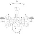
図1は、本発明の一実施の形態によるヘッドマウントディスプレイの表示部観察状態(ただし、使用者の図示は省略。)を示す概略斜視図である。図2は、図1に示すヘッドマウントディスプレイの待避状態を示す概略斜視図である。 FIG. 1 is a schematic perspective view showing a display unit observation state (not shown by a user) of a head mounted display according to an embodiment of the present invention. 2 is a schematic perspective view showing a retracted state of the head mounted display shown in FIG.
本実施の形態によるヘッドマウントディスプレイは、両耳を左右から押さえてヘッドマウントディスプレイを頭部に固定するイヤーパッド1,2を備えている。各イヤーパッド1,2の中にはスピーカ(図示せず)が設けられ、それぞれの耳に音声を出力する。各イヤーパッド1,2は、自在ヒンジ(図示せず)を介して保持部3,4にそれぞれ固定されている。左右の保持部3,4は、ヘッドバンド部5内に摺動自在に差し込まれ、ヘッドバンド部5により連結されている。ヘッドバンド部5は使用者の頭頂部に装着される。ヘッドバンド部5は弾力性を有し、イヤーパッド1、2を左右から耳部に押し付ける付勢力を与える。本実施の形態では、イヤーパッド1,2、保持部3,4及びヘッドバンド部5によって、使用者の頭部に装着される頭部装着部が構成されている。もっとも頭部装着部は、このような構成に限定されるものではなく、例えばヘルメット等でもよい。保持部3には、前記スピーカによる音声発生や表示部6による画像表示などに関する操作を行うための操作部7が設けられている。 The head mounted display according to the present embodiment includes
本実施の形態によるヘッドマウントディスプレイは、観察時に使用者の片眼の前方に配置され画像表示を行う表示部6と、保持部4と表示部6との間を連結するアーム部8と、保持部4とアーム部8の基端部とを連結する第1の連結機構9と、アーム部8の先端部とを連結する第2の連結機構10とを備えている。図1は、右耳にイヤーパッド1を当てるとともに左耳にイヤーパッド2を当てて、左眼で表示部6を観察する状態を示している。 The head mounted display according to the present embodiment includes a
本実施の形態では、第1の連結機構9は、図1に示すように、アーム部8の保持部4に対する2自由度の回動(回動方向θx1の回動と、回動方向θz1の回動)が可能でかつアーム部8の保持部4に対する位置決めが可能となるように、保持部4とアーム部8の基端部とを連結している。回動方向θx1は、使用者の両耳を結ぶ線に略平行な軸X1回りの回動方向である。回動方向θz1は、表示部6の観察時に略上下方向となる軸Z1回りの回動方向であり、表示部6の観察時に略水平方向とされる。軸X1と軸Z1とは直交している。 In the present embodiment, as shown in FIG. 1, the first connecting
本実施の形態では、第1の連結機構9は、アーム部8の保持部4に対する回動方向θx1の回動に関して、表示部6の観察時における位置決めのための所定の調整範囲内における複数の位置でアーム部8をクリックストップさせるクリック機構を含む。また、第1の連結機構9は、アーム部8の保持部4に対する回動方向θz1の回動に関して、表示部6の観察時における位置決めのための所定の調整範囲内における連続的な位置で自在にアーム部8を位置決めし得るように構成されている。 In the present embodiment, the first connecting
図3及び図4に第1の連結機構9の具体例を示す。図3は第1の連結機構9を示す概略平面図、図4は第1の連結機構9を示す概略正面図である。本例では、第1の連結機構9は、保持部4(図3及び図4では省略)に対して固定された基台11と、基台11に対して軸X1回りの回動方向θx1に回動自在に設けられた円盤12とを備えている。円盤12の外周には、所定の複数のクリックストップ位置において係止用の溝12a,12b,12cが形成されている。溝12a,12b,12cの位置については、後述する。板ばね13の一端側が基台11に固定され、板ばね13の他端側には溝12a,12b,12cとクリック係合する凸部13aが設けられている。板ばね13のバネ力により凸部13aが円盤12の外周に押し付けられ、円盤12が回動して凸部13aが溝12a,12b,12cと対面すると、凸部13aが溝12a,12b,12cに落ち込んで係合することで、クリック感が得られるようになっている。このように、本実施の形態では、円盤12の溝12a,12b,12cと板ばね13の凸部13aとによって、前記クリック機構が構成されている。 3 and 4 show specific examples of the
図3及び図4に示すように、アーム部8(図3及び図4では省略)がアーム保持部材14に固定されている。アーム保持部材14は、軸部材15等を用いることで、円盤12に対して、軸Z1回りの回動方向θz1に所定の摩擦力を持って回動自在に取り付けられている。アーム部8は、前記摩擦力によって、回動方向θz1の全範囲に渡る任意の位置に位置決めし得るようになっている。なお、本実施の形態では、アーム保持部材14(ひいては、アーム部8)の回動方向θz1の回動に関してはクリック機構は採用されていないが、その回動に関してもクリック機構を採用してもよい。 As shown in FIGS. 3 and 4, the arm portion 8 (not shown in FIGS. 3 and 4) is fixed to the
図5は、アーム部8の回動方向θx1の回動位置を模式的に示す概略側面図である。図5では、前述した左眼で表示部6を観察する図1に示す状態を実線で示している。本例では、左眼で表示部6を観察する場合のアーム部8の回動方向θx1の回動位置の調整範囲(左眼用調整範囲)は、例えば±30゜(+は水平方向Hに対する仰角側を示し、−は水平方向Hに対する俯角側を示す。)の範囲に設定され、この範囲内の5゜間隔の各位置がクリックストップ位置となるように、図4に示す円盤12の溝12aの位置が設定されている。ただし、図4では、図面表記の便宜上、溝12aの数は減らして示している。 FIG. 5 is a schematic side view schematically showing the rotation position of the
右眼で表示部6を観察する場合は、図1に示す状態に対してアーム部8が保持部4に対して回動方向θx1に180゜程度回動され、左耳にイヤーパッド1を当てるとともに右耳にイヤーパッド2を当てる。本例では、右眼で表示部6を観察する場合のアーム部8の回動方向θx1の回動位置の調整範囲(右眼用調整範囲)は、例えば±30゜(+は水平方向Hに対する仰角側を示し、−は水平方向Hに対する俯角側を示す。)の範囲に設定され、この範囲内の5゜間隔の各位置がクリックストップとなるように、図4に示す円盤12の溝12bの位置が設定されている。ただし、図4では、図面表記の便宜上、溝12bの数は減らして示している。 When the
このように、本例では、回動方向θx1の左眼用調整範囲と回動方向θx1の右眼用調整範囲とは、ちょうど180゜だけずれている。なお、左眼用と右眼用とを切り替える場合には、その切り替え状態に応じて、イヤーパッド1,2のスピーカの音声の左右や表示部6の表示の上下が、手動操作であるいはセンサによる自動切り替えによって反転される。 Thus, in this example, the adjustment range for the left eye in the rotation direction θx1 and the adjustment range for the right eye in the rotation direction θx1 are shifted by exactly 180 °. When switching between the left eye and the right eye, depending on the switching state, the left and right of the sound of the speakers of the
また、図5においてアーム部8が垂直方向Vとほぼ一致する回動方向θx1の回動位置(アーム部8の待避位置)に位置する場合、図2に示すように、表示部6が使用者の頭頂部付近に待避する。本実施の形態では、このアーム部8の待避位置がアーム部8のクリックストップ位置となるように、図4に示す円盤12の溝12cの位置が設定されている。 Further, in FIG. 5, when the
図1及び図2に示すように、アーム部8は、全体として円弧状をなしており、基端側アーム21と、先端側アーム22とを有している。基端側アーム21には先端側アーム22が摺動可能なように差し込まれ、先端側アーム22を基端側アーム21に対して円弧状の方向Rに摺動させることで、アーム部8の伸縮が可能なっている。なお、円弧状の方向Rは、軸X1及び軸Z1と直交する軸(図示せず)と軸X1とがなす平面内の方向である。 As shown in FIGS. 1 and 2, the
図6(a)はアーム部8の一部を拡大した概略断面図、図6(b)は図6(a)におけるA方向から見た図である。先端側アーム22には、規則的な間隔(例えば、1mm〜10mmの間の決まった値)で係止用凹部22aが設けられている。一方、基端側アーム21には切り欠き21aが設けられ、その結果ばね部21bが構成されている。このばね部21bは凸部21cを有する。先端側アーム22を基端側アーム21に差し込んで摺動させたとき、ばね部21bの凸部21cが係止用凹部22a内に嵌り込んで先端側アーム22を係止する。この係止力に抗して先端側アーム22を摺動させると、次の係止用凹部22a内にばね部21bの凸部21cが嵌り込むまで先端側アーム22が摺動する。すなわち、係止用凹部22a及びばね部21bの凸部21cは、アーム部8の複数の離散的な伸縮状態でクリックストップさせるクリック機構を構成している。このようにアーム部8の伸縮にクリック機構を採用すると、その調整が容易となるので好ましい。もっとも、アーム部8の伸縮に必ずしもクリック機構を採用する必要はない。 6A is a schematic cross-sectional view in which a part of the
本実施の形態では、第2の連結機構10は、図1に示すように、表示部6のアーム部8に対する3自由度の回動(回動方向θx2の回動と、回動方向θz2の回動と、回動方向θx3の回動)が可能でかつ表示部6のアーム部8に対する位置決めが可能となるように、アーム部8の先端部と表示部6とを連結している。回動方向θx2は、表示部6の観察時に軸X1と略平行となる軸X2回りの回動方向である。回動方向θz2は、表示部6の観察時に軸Z1と略平行となる軸Z2回りの回動方向である。軸X2と軸Z2とは直交している。回動方向θy2は、軸X2,Z2と直交した軸Y2回りの回動方向である。 In the present embodiment, as shown in FIG. 1, the second connecting
本実施の形態では、第2の連結機構10は、表示部6のアーム部8に対する回動方向θx2に関して、表示部6の観察時における位置決めのための所定の調整範囲内における連続的な位置で自在に表示部6を位置決めし得るように構成されている。また、第2の連結機構10は、表示部6のアーム部8に対する回動方向θz2に関して、表示部6の観察時における位置決めのための所定の調整範囲内における連続的な位置で自在に表示部6を位置決めし得るように構成されている。さらに、第2の連結機構10は、表示部6のアーム部8に対する回動方向θy2に関して、表示部6の観察時における位置決めのための所定の調整範囲内における連続的な位置で自在に表示部6を位置決めし得るように構成されている。 In the present embodiment, the second connecting
図7及び図8に第2の連結機構10の具体例を示す。図7は第2の連結機構10を示す概略斜視図、図8は第2の連結機構10を示す概略平面図である。本例では、第2の連結機構10は、アーム部8の先端側アーム22(図7及び図8では省略)に固定されたパイプ31と、パイプ31に固定されたブロック部材32と、断面L字状の回動部材33〜35とを有している。回動部材33は、軸部材36等を用いることで、ブロック部材32に対して、軸Z2回りの回動方向θz2に所定の摩擦力を持って回動自在に取り付けられている。回動部材34は、軸部材37等を用いることで、回動部材33に対して、軸X2回りの回動方向θx2に所定の摩擦力を持って回動自在に取り付けられている。回動部材35は、軸部材38等を用いることで、回動部材34に対して、軸Y2回りの回動方向θy2に所定の摩擦力を持って回動自在に取り付けられている。図7及び図8には示していないが、回動部材35に対して表示部6が固定されている。これらの回動方向θz2,θx2,θy2の回動のうち、回動方向θz2の回動に関してのみ、1箇所だけのクリックストップ位置を有するクリック機構(図示せず)が採用されている。このクリックストップ位置は、図8中に実線で示す回動方向θz2の回動位置である。図8中の破線で示す回動方向θz2の回動位置は、図1に示すように軸X2が軸X1と平行となる位置である。図8中に実線で示す回動方向θz2の回動位置(クリックストップ位置)は、図8中に破線で示す位置(図1中に示す位置に相当)から回動方向θz2に使用者の顔から遠ざかる向きに例えば20゜だけずれた位置である。回動部材33は、このクリックストップ位置で軽く係止されるようになっている。図1に示す観察状態から図2に示す待避状態に移行する際に、最初に表示部6を回動方向θz2に顔から遠ざかる向きに回動させてこのクリックストップ位置でクリックストップさせ、その後アーム部8を回動方向θx1に回動させて表示部6を頭頂部付近に待避させれば、表示部6が使用者の髪などに触れ難くなり、表示部6に汚れが付着し難くなる。回動方向θz2に関して前述したクリック機構を採用することで、このような待避動作を容易に行うことができるので、好ましい。もっとも、回動方向θz2に関しても必ずしもクリック機構を採用する必要はない。 7 and 8 show a specific example of the
そして、本実施の形態では、観察時に一旦調整した表示部6の向きや位置に従った表示部6のアーム部8に対する位置関係が、前述した待避動作によって極力変更されてしまわないように、前述した各部の摩擦力及び回動方向θx1のクリック係止力の大きさが設定されている。例えば、アーム部8の保持部4に対する軸X1回りの回動方向θx1の回動と、表示部6のアーム部8に対する軸X2回りの回動方向θx2とは対応しているが、アーム部8の回動方向θx1の回動に関する保持トルクは、表示部6の回動方向θ2の回動に関する保持トルクよりも、小さく設定されている。これにより、表示部6の回動方向θx1,θx2の向きを一旦調整した後、表示部6を図2に示す状態に待避させる際に、表示部6のアーム部8に対する回動方向θx2の回動位置は保持されたまま、アーム部8を保持部4に対して回動方向θx1へ回動させることができる。よって、再び、図2に示す待避状態から図1に示す観察状態に戻すときに、表示部6のアーム部8に対する回動方向θx2の回動位置を再調整する必要がなくなり、使い勝手が向上する。 In the present embodiment, the positional relationship of the
なお、前述した待避動作とは関係ないが、アーム部8の保持部4に対する回動方向θz1の回動に関する保持トルクを、この回動に対応する表示部6のアーム部8に対する回動方向θz2の回動に関する保持トルクよりも小さく設定しておくことで、表示部6の軸Z1,Z2回りの向きの調整に関して使い勝手が向上する。 Although not related to the above-described retracting operation, the holding torque related to the rotation of the rotation direction θz1 with respect to the holding
また、本実施の形態では、前述したように、アーム部8の保持部4に対する軸X1回りの回動方向θx1の回動に関しては、所定の調整範囲(左目用±30゜の範囲、右眼用±30゜の範囲)の例えば5゜ずつの位置をクリックストップ位置としたクリック機構が採用される一方、アーム部8の回動方向θx1の回動に対応する表示部6のアーム部8に対する軸X2回りの回動方向θx2の回動に関しては、少なくとも表示部6の観察時の調整範囲においていわゆるフリーストップが採用されている。したがって、表示部6の軸X1,X2回りの向きを調整するに際し、アーム部8の保持部4に対する回動方向θx1の回動においてクリックストップによる粗調整を行い、表示部6のアーム部8に対する回動方向θx2の回動において微調整を行うことができる。よって、表示部6の向きの迅速かつ正確な調整を実現することができ、使い勝手が向上する。そして、本実施の形態では、アーム部8の保持部4に対する軸X1回りの回動方向θx1の回動に関して、左眼用調整範囲と右眼用調整範囲の両方にクリックストップ位置が設定されているので、いずれの眼で観察するように切り替えて使用する場合であっても、表示部6の向きの迅速かつ正確な調整を実現することができ、使い勝手が向上する。もっとも、本発明は片眼用のヘッドマウントディスプレイに適用してもよい。 In the present embodiment, as described above, with respect to the rotation in the rotation direction θx1 around the axis X1 with respect to the holding
なお、本実施の形態では、前述したように、アーム部8の保持部4に対する軸Z1回りの回動に関していわゆるフリーストップが採用されているが、アーム部8の保持部4に対する軸Z1回りの回動に関して、表示部6の観察時の位置決めのための調整範囲において複数のクリックストップ位置を持つクリック機構を採用してもよい。 In this embodiment, as described above, a so-called free stop is adopted for the rotation of the
また、本実施の形態では、アーム部8の待避位置(図2に示す位置)がアーム部8の保持部4に対する回動方向θx1の回動のクリックストップ位置とされているので、表示部6を頭頂部付近に待避させる際の位置決めが容易となり、使い勝手が向上する。 Further, in the present embodiment, the retracted position (position shown in FIG. 2) of the
さらに、本実施の形態では、第1の連結機構9による回動の自由度がθx1,θz1の2である一方、第2の連結機構10による回動の自由度がθx2,θz2,θy2の3であり、前者の自由度よりも後者の自由度の方が高い。したがって、表示部6のアーム部8に対する調整の方が細かく行うことができるので、使い勝手を向上させることができる。また、第1の連結機構9による回動の自由度も3にする場合よりも、コスト低減を図ることができる。 Furthermore, in the present embodiment, the degree of freedom of rotation by the first connecting
さらにまた、本実施の形態では、アーム部8が円弧状をなしているので、アーム部8が一直線状をなす場合に比べて、アーム部8が使用者の頬から遠ざかるため、使用者にとってアーム部8の煩わしさが低減され、使い勝手が向上する。また、このようにアーム部8が円弧状をなし、更にアーム部8が当該円弧状の方向Rに沿って伸縮するため、表示部6を眼から離そうとしてアーム部8を伸ばすと、表示部6が上下方向の軸回りに傾いてしまう。しかし、本実施の形態では、第1の連結機構9は、アーム部が保持部4に対して軸Z1回りの回動方向θz1に回動可能になるように構成され、第2の連結機構10は、表示部6がアーム部8に対して軸Z2回りの回動方向θz2に回動可能となるように構成されているので、アーム部8の伸縮に伴って生ずる表示部6の傾きを容易に補正することができ、使い勝手が向上する。 Furthermore, in the present embodiment, since the
以上、本発明の一実施の形態について説明したが、本発明はこの実施の形態に限定されるものではない。 Although one embodiment of the present invention has been described above, the present invention is not limited to this embodiment.
例えば、本発明では、第2の連結機構10として、前述した図7に示すような構成のものに代えて、いわゆるボールジョイントを採用してもよい。 For example, in the present invention, a so-called ball joint may be employed as the
また、本発明では、第1の連結機構9に関して、表示部6の観察時の所定の調整範囲内における、アーム部8の保持部4に対する軸X1回りの回動方向θx1の回動のクリックストップ位置を、1つだけにしてもよい。この場合、表示部6の観察時には、アーム部8を常に当該クリックストップ位置に位置させ、表示部6の軸X1,X2回りの向きの調整は、表示部6のアーム部8に対する回動方向θx2の回動で行えばよい。 Further, in the present invention, with respect to the first connecting
さらに、本発明では、第1の連結機構9を、アーム部8の保持部4に対する軸X1回りの回動方向θx1の回動に関してもクリック機構を採用せずにフリーストップを行うように構成し、やはり、アーム部8の回動方向θx1の回動に関する保持トルクは、表示部6の回動方向θ2の回動に関する保持トルクよりも、小さく設定してもよい。この場合であっても、待避動作に伴う再調整(表示部6のアーム部8に対する回動方向θx1の回動位置の再調整)が必要なくなる。 Further, in the present invention, the
4 保持部(頭部装着部の一部)
6 表示部
8 アーム部
9 第1の連結機構
10 第2の連結機構4 Holding part (part of head mounting part)
6
Claims (15)
Translated fromJapanese観察時に前記使用者の片眼の前方に配置される表示部と、
前記頭部装着部と前記表示部との間を連結するアーム部と、
前記アーム部の前記頭部装着部に対する1自由度以上の回動が可能でかつ前記アーム部の前記頭部装着部に対する位置決めが可能となるように、前記頭部装着部と前記アーム部の基端部とを連結する第1の連結機構と、
前記表示部の前記アーム部に対する1自由度以上の回動が可能でかつ前記表示部の前記アーム部に対する位置決めが可能となるように、前記アーム部の先端部と前記表示部とを連結する第2の連結機構と、
を備え、
前記第1の連結機構は、前記アーム部の前記頭部装着部に対する少なくとも1自由度の回動に関して、前記表示部の観察時における位置決めのための所定の調整範囲内における離散的な1つ又は複数の位置で前記アーム部をクリックストップさせるクリック機構を含み、
前記第2の連動機構は、前記アーム部の前記頭部装着部に対する前記少なくとも1自由度の回動に対応する回動であって前記表示部の前記アーム部に対する少なくとも1自由度の回動に関して、前記表示部の観察時における位置決めのための所定の調整範囲内における連続的な位置で自在に前記表示部を位置決めし得るように、構成された、
ことを特徴とするヘッドマウントディスプレイ。A head mounting part to be mounted on the user's head;
A display unit disposed in front of one eye of the user during observation;
An arm portion connecting between the head mounting portion and the display portion;
The base of the head mounting portion and the arm portion is configured such that the arm portion can be rotated with one or more degrees of freedom with respect to the head mounting portion, and the arm portion can be positioned with respect to the head mounting portion. A first coupling mechanism that couples the end portions;
A first connecting the display unit and the tip of the arm unit so that the display unit can rotate more than one degree of freedom with respect to the arm unit and can be positioned with respect to the arm unit. Two coupling mechanisms;
With
The first connection mechanism may be a discrete one within a predetermined adjustment range for positioning when observing the display unit, or at least one degree of freedom of rotation of the arm unit with respect to the head mounting unit. Including a click mechanism for clicking and stopping the arm portion at a plurality of positions;
The second interlocking mechanism is a rotation corresponding to the rotation of the at least one degree of freedom of the arm unit with respect to the head mounting unit, and is related to the rotation of the display unit with respect to the arm unit of at least one degree of freedom. The display unit can be freely positioned at continuous positions within a predetermined adjustment range for positioning when observing the display unit.
A head-mounted display characterized by that.
前記所定の調整範囲は、左眼用の調整範囲及び右眼用の調整範囲を含むことを特徴とする請求項2又は3記載のヘッドマウントディスプレイ。A left eye is obtained by rotating about an axis substantially parallel to a line connecting the user's ears to the head mounting portion of the arm portion and switching the left and right mounting of the head mounting portion to the user. Can be used by switching between for the right eye and for the right eye,
4. The head mounted display according to claim 2, wherein the predetermined adjustment range includes an adjustment range for the left eye and an adjustment range for the right eye.
前記第1の連結部は、前記表示部の観察時の状態において略水平方向となる方向に前記アーム部が前記頭部装着部に対して回動可能となるように、前記頭部装着部と前記アーム部の基端部とを連結し、
前記第2の連結部は、前記表示部の観察時の状態において略水平方向となる方向に前記表示部が前記アーム部に対して回動可能となるように、前記アーム部の先端部と前記表示部とを連結する、
ことを特徴とする請求項1乃至6のいずれかに記載のヘッドマウントディスプレイ。The arm portion has an arc shape and is configured to be stretchable along the arc shape,
The first connecting portion includes the head mounting portion and the head mounting portion so that the arm portion can rotate with respect to the head mounting portion in a direction that is substantially horizontal when the display portion is observed. Connecting the base end of the arm part;
The second connecting portion includes a distal end portion of the arm portion and the end portion of the arm portion so that the display portion is rotatable with respect to the arm portion in a direction that is substantially horizontal when the display portion is observed. Connecting the display unit,
The head mounted display according to any one of claims 1 to 6.
観察時に前記使用者の片眼の前方に配置される表示部と、
前記頭部装着部と前記表示部との間を連結するアーム部と、
前記アーム部の前記頭部装着部に対する1自由度以上の回動が可能でかつ前記アーム部の前記頭部装着部に対する位置決めが可能となるように、前記頭部装着部と前記アーム部の基端部とを連結する第1の連結機構と、
前記表示部の前記アーム部に対する1自由度以上の回動が可能でかつ前記表示部の前記アーム部に対する位置決めが可能となるように、前記アーム部の先端部と前記表示部とを連結する第2の連結機構と、
を備え、
前記アーム部の前記頭部装着部に対する少なくとも1自由度の回動に関する前記アーム部の保持トルクは、前記アーム部の前記頭部装着部に対する前記少なくとも1自由度の回動に対応する回動であって前記表示部の前記アーム部に対する少なくとも1自由度の回動に関する前記表示部の保持トルクよりも、小さいことを特徴とするヘッドマウントディスプレイ。A head mounting part to be mounted on the user's head;
A display unit disposed in front of one eye of the user during observation;
An arm portion connecting between the head mounting portion and the display portion;
The base of the head mounting portion and the arm portion is configured such that the arm portion can be rotated with one or more degrees of freedom with respect to the head mounting portion, and the arm portion can be positioned with respect to the head mounting portion. A first coupling mechanism that couples the end portions;
A first connecting the display unit and the tip of the arm unit so that the display unit can rotate more than one degree of freedom with respect to the arm unit and can be positioned with respect to the arm unit. Two coupling mechanisms;
With
The holding torque of the arm part related to the rotation of the arm part with respect to the head mounting part with respect to the head mounting part is a rotation corresponding to the rotation of the arm part with respect to the head mounting part with respect to the at least one degree of freedom. The head mounted display is characterized by being smaller than the holding torque of the display unit relating to the rotation of the display unit with respect to the arm unit with at least one degree of freedom.
観察時に前記使用者の片眼の前方に配置される表示部と、
前記頭部装着部と前記表示部との間を連結するアーム部と、
前記アーム部の前記頭部装着部に対する1自由度以上の回動が可能でかつ前記アーム部の前記頭部装着部に対する位置決めが可能となるように、前記頭部装着部と前記アーム部の基端部とを連結する第1の連結機構と、
前記表示部の前記アーム部に対する1自由度以上の回動が可能でかつ前記表示部の前記アーム部に対する位置決めが可能となるように、前記アーム部の先端部と前記表示部とを連結する第2の連結機構と、
を備え、
前記アーム部が円弧状をなすとともに当該円弧状に沿って伸縮可能となるように構成され、
前記第1の連結部は、前記表示部の観察時の状態において略水平方向となる方向に前記アーム部が前記頭部装着部に対して回動可能となるように、前記頭部装着部と前記アーム部の基端部とを連結し、
前記第2の連結部は、前記表示部の観察時の状態において略水平方向となる方向に前記表示部が前記アーム部に対して回動可能となるように、前記アーム部の先端部と前記表示部とを連結する、
ことを特徴とするヘッドマウントディスプレイ。A head mounting part to be mounted on the user's head;
A display unit disposed in front of one eye of the user during observation;
An arm portion connecting between the head mounting portion and the display portion;
The base of the head mounting portion and the arm portion is configured such that the arm portion can be rotated with one or more degrees of freedom with respect to the head mounting portion, and the arm portion can be positioned with respect to the head mounting portion. A first coupling mechanism that couples the end portions;
A first connecting the display unit and the tip of the arm unit so that the display unit can rotate more than one degree of freedom with respect to the arm unit and can be positioned with respect to the arm unit. Two coupling mechanisms;
With
The arm portion has an arc shape and is configured to be stretchable along the arc shape,
The first connecting portion includes the head mounting portion and the head mounting portion so that the arm portion can rotate with respect to the head mounting portion in a direction that is substantially horizontal when the display portion is observed. Connecting the base end of the arm part;
The second connecting portion includes a distal end portion of the arm portion and the end portion of the arm portion so that the display portion is rotatable with respect to the arm portion in a direction that is substantially horizontal when the display portion is observed. Connecting the display unit,
A head-mounted display characterized by that.
Priority Applications (1)
| Application Number | Priority Date | Filing Date | Title |
|---|---|---|---|
| JP2007193149AJP2009033308A (en) | 2007-07-25 | 2007-07-25 | Head mounted display |
Applications Claiming Priority (1)
| Application Number | Priority Date | Filing Date | Title |
|---|---|---|---|
| JP2007193149AJP2009033308A (en) | 2007-07-25 | 2007-07-25 | Head mounted display |
Publications (1)
| Publication Number | Publication Date |
|---|---|
| JP2009033308Atrue JP2009033308A (en) | 2009-02-12 |
Family
ID=40403350
Family Applications (1)
| Application Number | Title | Priority Date | Filing Date |
|---|---|---|---|
| JP2007193149APendingJP2009033308A (en) | 2007-07-25 | 2007-07-25 | Head mounted display |
Country Status (1)
| Country | Link |
|---|---|
| JP (1) | JP2009033308A (en) |
Cited By (13)
| Publication number | Priority date | Publication date | Assignee | Title |
|---|---|---|---|---|
| WO2016107419A1 (en)* | 2014-12-31 | 2016-07-07 | 青岛歌尔声学科技有限公司 | Adjustable head-mounted display |
| JP2017069736A (en)* | 2015-09-30 | 2017-04-06 | ブラザー工業株式会社 | Head mounted display |
| WO2018118433A1 (en) | 2016-12-23 | 2018-06-28 | Realwear, Incorporated | Articulating components for a head-mounted display |
| CN108700742A (en)* | 2016-01-06 | 2018-10-23 | 伊奎蒂公司 | Head-mounted display with swivel display |
| WO2019050843A1 (en) | 2017-09-06 | 2019-03-14 | Realwear, Incorporated | Audible and visual operational modes for a head-mounted display device |
| US10936872B2 (en) | 2016-12-23 | 2021-03-02 | Realwear, Inc. | Hands-free contextually aware object interaction for wearable display |
| US11099716B2 (en) | 2016-12-23 | 2021-08-24 | Realwear, Inc. | Context based content navigation for wearable display |
| CN113534470A (en)* | 2021-08-03 | 2021-10-22 | 瑞欧威尔(上海)智能科技有限公司 | Variable FOV display system |
| WO2022055153A1 (en)* | 2020-09-14 | 2022-03-17 | 주식회사 메가젠임플란트 | Head mounted display device |
| US11340465B2 (en) | 2016-12-23 | 2022-05-24 | Realwear, Inc. | Head-mounted display with modular components |
| US11409497B2 (en) | 2016-12-23 | 2022-08-09 | Realwear, Inc. | Hands-free navigation of touch-based operating systems |
| US11507216B2 (en) | 2016-12-23 | 2022-11-22 | Realwear, Inc. | Customizing user interfaces of binary applications |
| USD1059729S1 (en) | 2022-08-31 | 2025-02-04 | Vuzix Corporation | Headband |
- 2007
- 2007-07-25JPJP2007193149Apatent/JP2009033308A/enactivePending
Cited By (29)
| Publication number | Priority date | Publication date | Assignee | Title |
|---|---|---|---|---|
| WO2016107419A1 (en)* | 2014-12-31 | 2016-07-07 | 青岛歌尔声学科技有限公司 | Adjustable head-mounted display |
| US10353206B2 (en) | 2014-12-31 | 2019-07-16 | Qingdao Goertek Technology Co., Ltd. | Adjustable head-mounted display |
| US10459235B2 (en) | 2015-09-30 | 2019-10-29 | Brother Kogyo Kabushiki Kaisha | Head-mounted display |
| JP2017069736A (en)* | 2015-09-30 | 2017-04-06 | ブラザー工業株式会社 | Head mounted display |
| WO2017057084A1 (en)* | 2015-09-30 | 2017-04-06 | ブラザー工業株式会社 | Head-mounted display |
| US11988842B2 (en) | 2016-01-06 | 2024-05-21 | Vuzix Corporation | Head-mounted display with pivoting display |
| CN108700742A (en)* | 2016-01-06 | 2018-10-23 | 伊奎蒂公司 | Head-mounted display with swivel display |
| JP2019508925A (en)* | 2016-01-06 | 2019-03-28 | ビュージックス コーポレーションVuzix Corporation | Head mounted display with rotating display |
| US11385469B2 (en) | 2016-01-06 | 2022-07-12 | Vuzix Corporation | Head-mounted display with pivoting display |
| US11409497B2 (en) | 2016-12-23 | 2022-08-09 | Realwear, Inc. | Hands-free navigation of touch-based operating systems |
| US11340465B2 (en) | 2016-12-23 | 2022-05-24 | Realwear, Inc. | Head-mounted display with modular components |
| EP3559730A4 (en)* | 2016-12-23 | 2020-09-02 | Realwear, Incorporated | ARTICULATED COMPONENTS FOR A HEAD MOUNTED DISPLAY |
| US10936872B2 (en) | 2016-12-23 | 2021-03-02 | Realwear, Inc. | Hands-free contextually aware object interaction for wearable display |
| WO2018118433A1 (en) | 2016-12-23 | 2018-06-28 | Realwear, Incorporated | Articulating components for a head-mounted display |
| US11947752B2 (en) | 2016-12-23 | 2024-04-02 | Realwear, Inc. | Customizing user interfaces of binary applications |
| US11099716B2 (en) | 2016-12-23 | 2021-08-24 | Realwear, Inc. | Context based content navigation for wearable display |
| US11507216B2 (en) | 2016-12-23 | 2022-11-22 | Realwear, Inc. | Customizing user interfaces of binary applications |
| CN110100201A (en)* | 2016-12-23 | 2019-08-06 | 瑞欧威尔股份有限公司 | Hinge member for head-mounted display |
| US11061527B2 (en) | 2017-09-06 | 2021-07-13 | Realwear, Inc. | Audible and visual operational modes for a head-mounted display device |
| WO2019050843A1 (en) | 2017-09-06 | 2019-03-14 | Realwear, Incorporated | Audible and visual operational modes for a head-mounted display device |
| CN111194424A (en)* | 2017-09-06 | 2020-05-22 | 瑞欧威尔公司 | Audible and visual modes of operation for head mounted display devices |
| EP3679418A4 (en)* | 2017-09-06 | 2021-05-26 | Realwear, Incorporated | AUDIBLE AND VISUAL OPERATING MODES FOR A HEAD MOUNT DISPLAY DEVICE |
| KR20220035782A (en)* | 2020-09-14 | 2022-03-22 | 주식회사 메가젠임플란트 | head mounted display device |
| WO2022055153A1 (en)* | 2020-09-14 | 2022-03-17 | 주식회사 메가젠임플란트 | Head mounted display device |
| KR102614739B1 (en) | 2020-09-14 | 2023-12-15 | 주식회사 메가젠임플란트 | Head mounted display device |
| US11927764B2 (en) | 2020-09-14 | 2024-03-12 | Megagen Implant Co., Ltd. | Head mounted display device |
| CN113534470A (en)* | 2021-08-03 | 2021-10-22 | 瑞欧威尔(上海)智能科技有限公司 | Variable FOV display system |
| CN113534470B (en)* | 2021-08-03 | 2023-07-25 | 瑞欧威尔(上海)智能科技有限公司 | Variable FOV display system |
| USD1059729S1 (en) | 2022-08-31 | 2025-02-04 | Vuzix Corporation | Headband |
Similar Documents
| Publication | Publication Date | Title |
|---|---|---|
| JP2009033308A (en) | Head mounted display | |
| US10905186B2 (en) | Head-mounted display device | |
| JP6878488B2 (en) | Synchronized inset headphones | |
| JP3880294B2 (en) | Head mounting mechanism and head mounting device using the same | |
| JP5163493B2 (en) | Output device | |
| KR20060051367A (en) | Headphone | |
| JP5072280B2 (en) | Image display device | |
| JP4572737B2 (en) | Head mounted display | |
| JP4622937B2 (en) | Head-mounted display device | |
| JPWO2018003084A1 (en) | Wearable device and adjustment method | |
| CN101018953A (en) | Two-axis swivel joint | |
| US8204267B2 (en) | Earphone and headset | |
| JP6916135B2 (en) | robot | |
| EP2692296B1 (en) | Portable ultrasound system | |
| JP2012105117A (en) | Head-mounted image display device | |
| JP2007064997A (en) | Head mounted image display device | |
| JP2006142023A (en) | Ceiling mounted x-ray tube support | |
| JP2010074220A (en) | Head mount type image display device | |
| JP6021507B2 (en) | Head-mounted display device | |
| JP7665353B2 (en) | Handheld display device and handheld unit | |
| JP2012089984A (en) | Head-mounted image display device | |
| EP4111086B1 (en) | Device for rotating a monitor around an instrument | |
| JP2009055598A (en) | Video camera | |
| JP2008147741A (en) | Head mounted display | |
| JP4517738B2 (en) | Anti-rotation device for auxiliary optical system |