JP2009025128A - Map display device, map display method, and computer program - Google Patents
Map display device, map display method, and computer programDownload PDFInfo
- Publication number
- JP2009025128A JP2009025128AJP2007188090AJP2007188090AJP2009025128AJP 2009025128 AJP2009025128 AJP 2009025128AJP 2007188090 AJP2007188090 AJP 2007188090AJP 2007188090 AJP2007188090 AJP 2007188090AJP 2009025128 AJP2009025128 AJP 2009025128A
- Authority
- JP
- Japan
- Prior art keywords
- vehicle
- battery
- travelable range
- charging
- travelable
- Prior art date
- Legal status (The legal status is an assumption and is not a legal conclusion. Google has not performed a legal analysis and makes no representation as to the accuracy of the status listed.)
- Granted
Links
Images


Classifications
- G—PHYSICS
- G01—MEASURING; TESTING
- G01C—MEASURING DISTANCES, LEVELS OR BEARINGS; SURVEYING; NAVIGATION; GYROSCOPIC INSTRUMENTS; PHOTOGRAMMETRY OR VIDEOGRAMMETRY
- G01C21/00—Navigation; Navigational instruments not provided for in groups G01C1/00 - G01C19/00
- G01C21/26—Navigation; Navigational instruments not provided for in groups G01C1/00 - G01C19/00 specially adapted for navigation in a road network
- G01C21/34—Route searching; Route guidance
- G01C21/36—Input/output arrangements for on-board computers
- G01C21/3667—Display of a road map
- G01C21/3676—Overview of the route on the road map
- B—PERFORMING OPERATIONS; TRANSPORTING
- B60—VEHICLES IN GENERAL
- B60K—ARRANGEMENT OR MOUNTING OF PROPULSION UNITS OR OF TRANSMISSIONS IN VEHICLES; ARRANGEMENT OR MOUNTING OF PLURAL DIVERSE PRIME-MOVERS IN VEHICLES; AUXILIARY DRIVES FOR VEHICLES; INSTRUMENTATION OR DASHBOARDS FOR VEHICLES; ARRANGEMENTS IN CONNECTION WITH COOLING, AIR INTAKE, GAS EXHAUST OR FUEL SUPPLY OF PROPULSION UNITS IN VEHICLES
- B60K35/00—Instruments specially adapted for vehicles; Arrangement of instruments in or on vehicles
- B60K35/20—Output arrangements, i.e. from vehicle to user, associated with vehicle functions or specially adapted therefor
- B60K35/28—Output arrangements, i.e. from vehicle to user, associated with vehicle functions or specially adapted therefor characterised by the type of the output information, e.g. video entertainment or vehicle dynamics information; characterised by the purpose of the output information, e.g. for attracting the attention of the driver
- B—PERFORMING OPERATIONS; TRANSPORTING
- B60—VEHICLES IN GENERAL
- B60L—PROPULSION OF ELECTRICALLY-PROPELLED VEHICLES; SUPPLYING ELECTRIC POWER FOR AUXILIARY EQUIPMENT OF ELECTRICALLY-PROPELLED VEHICLES; ELECTRODYNAMIC BRAKE SYSTEMS FOR VEHICLES IN GENERAL; MAGNETIC SUSPENSION OR LEVITATION FOR VEHICLES; MONITORING OPERATING VARIABLES OF ELECTRICALLY-PROPELLED VEHICLES; ELECTRIC SAFETY DEVICES FOR ELECTRICALLY-PROPELLED VEHICLES
- B60L15/00—Methods, circuits, or devices for controlling the traction-motor speed of electrically-propelled vehicles
- B60L15/20—Methods, circuits, or devices for controlling the traction-motor speed of electrically-propelled vehicles for control of the vehicle or its driving motor to achieve a desired performance, e.g. speed, torque, programmed variation of speed
- B60L15/2045—Methods, circuits, or devices for controlling the traction-motor speed of electrically-propelled vehicles for control of the vehicle or its driving motor to achieve a desired performance, e.g. speed, torque, programmed variation of speed for optimising the use of energy
- B—PERFORMING OPERATIONS; TRANSPORTING
- B60—VEHICLES IN GENERAL
- B60L—PROPULSION OF ELECTRICALLY-PROPELLED VEHICLES; SUPPLYING ELECTRIC POWER FOR AUXILIARY EQUIPMENT OF ELECTRICALLY-PROPELLED VEHICLES; ELECTRODYNAMIC BRAKE SYSTEMS FOR VEHICLES IN GENERAL; MAGNETIC SUSPENSION OR LEVITATION FOR VEHICLES; MONITORING OPERATING VARIABLES OF ELECTRICALLY-PROPELLED VEHICLES; ELECTRIC SAFETY DEVICES FOR ELECTRICALLY-PROPELLED VEHICLES
- B60L50/00—Electric propulsion with power supplied within the vehicle
- B60L50/10—Electric propulsion with power supplied within the vehicle using propulsion power supplied by engine-driven generators, e.g. generators driven by combustion engines
- B60L50/16—Electric propulsion with power supplied within the vehicle using propulsion power supplied by engine-driven generators, e.g. generators driven by combustion engines with provision for separate direct mechanical propulsion
- B—PERFORMING OPERATIONS; TRANSPORTING
- B60—VEHICLES IN GENERAL
- B60L—PROPULSION OF ELECTRICALLY-PROPELLED VEHICLES; SUPPLYING ELECTRIC POWER FOR AUXILIARY EQUIPMENT OF ELECTRICALLY-PROPELLED VEHICLES; ELECTRODYNAMIC BRAKE SYSTEMS FOR VEHICLES IN GENERAL; MAGNETIC SUSPENSION OR LEVITATION FOR VEHICLES; MONITORING OPERATING VARIABLES OF ELECTRICALLY-PROPELLED VEHICLES; ELECTRIC SAFETY DEVICES FOR ELECTRICALLY-PROPELLED VEHICLES
- B60L50/00—Electric propulsion with power supplied within the vehicle
- B60L50/50—Electric propulsion with power supplied within the vehicle using propulsion power supplied by batteries or fuel cells
- B60L50/60—Electric propulsion with power supplied within the vehicle using propulsion power supplied by batteries or fuel cells using power supplied by batteries
- B60L50/61—Electric propulsion with power supplied within the vehicle using propulsion power supplied by batteries or fuel cells using power supplied by batteries by batteries charged by engine-driven generators, e.g. series hybrid electric vehicles
- B—PERFORMING OPERATIONS; TRANSPORTING
- B60—VEHICLES IN GENERAL
- B60L—PROPULSION OF ELECTRICALLY-PROPELLED VEHICLES; SUPPLYING ELECTRIC POWER FOR AUXILIARY EQUIPMENT OF ELECTRICALLY-PROPELLED VEHICLES; ELECTRODYNAMIC BRAKE SYSTEMS FOR VEHICLES IN GENERAL; MAGNETIC SUSPENSION OR LEVITATION FOR VEHICLES; MONITORING OPERATING VARIABLES OF ELECTRICALLY-PROPELLED VEHICLES; ELECTRIC SAFETY DEVICES FOR ELECTRICALLY-PROPELLED VEHICLES
- B60L58/00—Methods or circuit arrangements for monitoring or controlling batteries or fuel cells, specially adapted for electric vehicles
- B60L58/10—Methods or circuit arrangements for monitoring or controlling batteries or fuel cells, specially adapted for electric vehicles for monitoring or controlling batteries
- B60L58/12—Methods or circuit arrangements for monitoring or controlling batteries or fuel cells, specially adapted for electric vehicles for monitoring or controlling batteries responding to state of charge [SoC]
- G—PHYSICS
- G01—MEASURING; TESTING
- G01C—MEASURING DISTANCES, LEVELS OR BEARINGS; SURVEYING; NAVIGATION; GYROSCOPIC INSTRUMENTS; PHOTOGRAMMETRY OR VIDEOGRAMMETRY
- G01C21/00—Navigation; Navigational instruments not provided for in groups G01C1/00 - G01C19/00
- G01C21/26—Navigation; Navigational instruments not provided for in groups G01C1/00 - G01C19/00 specially adapted for navigation in a road network
- G01C21/34—Route searching; Route guidance
- G01C21/3453—Special cost functions, i.e. other than distance or default speed limit of road segments
- G01C21/3469—Fuel consumption; Energy use; Emission aspects
- G—PHYSICS
- G09—EDUCATION; CRYPTOGRAPHY; DISPLAY; ADVERTISING; SEALS
- G09B—EDUCATIONAL OR DEMONSTRATION APPLIANCES; APPLIANCES FOR TEACHING, OR COMMUNICATING WITH, THE BLIND, DEAF OR MUTE; MODELS; PLANETARIA; GLOBES; MAPS; DIAGRAMS
- G09B29/00—Maps; Plans; Charts; Diagrams, e.g. route diagram
- G09B29/10—Map spot or coordinate position indicators; Map reading aids
- G09B29/106—Map spot or coordinate position indicators; Map reading aids using electronic means
- B—PERFORMING OPERATIONS; TRANSPORTING
- B60—VEHICLES IN GENERAL
- B60K—ARRANGEMENT OR MOUNTING OF PROPULSION UNITS OR OF TRANSMISSIONS IN VEHICLES; ARRANGEMENT OR MOUNTING OF PLURAL DIVERSE PRIME-MOVERS IN VEHICLES; AUXILIARY DRIVES FOR VEHICLES; INSTRUMENTATION OR DASHBOARDS FOR VEHICLES; ARRANGEMENTS IN CONNECTION WITH COOLING, AIR INTAKE, GAS EXHAUST OR FUEL SUPPLY OF PROPULSION UNITS IN VEHICLES
- B60K2360/00—Indexing scheme associated with groups B60K35/00 or B60K37/00 relating to details of instruments or dashboards
- B60K2360/16—Type of output information
- B60K2360/172—Driving mode indication
- B—PERFORMING OPERATIONS; TRANSPORTING
- B60—VEHICLES IN GENERAL
- B60L—PROPULSION OF ELECTRICALLY-PROPELLED VEHICLES; SUPPLYING ELECTRIC POWER FOR AUXILIARY EQUIPMENT OF ELECTRICALLY-PROPELLED VEHICLES; ELECTRODYNAMIC BRAKE SYSTEMS FOR VEHICLES IN GENERAL; MAGNETIC SUSPENSION OR LEVITATION FOR VEHICLES; MONITORING OPERATING VARIABLES OF ELECTRICALLY-PROPELLED VEHICLES; ELECTRIC SAFETY DEVICES FOR ELECTRICALLY-PROPELLED VEHICLES
- B60L2240/00—Control parameters of input or output; Target parameters
- B60L2240/10—Vehicle control parameters
- B60L2240/12—Speed
- B—PERFORMING OPERATIONS; TRANSPORTING
- B60—VEHICLES IN GENERAL
- B60L—PROPULSION OF ELECTRICALLY-PROPELLED VEHICLES; SUPPLYING ELECTRIC POWER FOR AUXILIARY EQUIPMENT OF ELECTRICALLY-PROPELLED VEHICLES; ELECTRODYNAMIC BRAKE SYSTEMS FOR VEHICLES IN GENERAL; MAGNETIC SUSPENSION OR LEVITATION FOR VEHICLES; MONITORING OPERATING VARIABLES OF ELECTRICALLY-PROPELLED VEHICLES; ELECTRIC SAFETY DEVICES FOR ELECTRICALLY-PROPELLED VEHICLES
- B60L2240/00—Control parameters of input or output; Target parameters
- B60L2240/40—Drive Train control parameters
- B60L2240/42—Drive Train control parameters related to electric machines
- B60L2240/423—Torque
- B—PERFORMING OPERATIONS; TRANSPORTING
- B60—VEHICLES IN GENERAL
- B60L—PROPULSION OF ELECTRICALLY-PROPELLED VEHICLES; SUPPLYING ELECTRIC POWER FOR AUXILIARY EQUIPMENT OF ELECTRICALLY-PROPELLED VEHICLES; ELECTRODYNAMIC BRAKE SYSTEMS FOR VEHICLES IN GENERAL; MAGNETIC SUSPENSION OR LEVITATION FOR VEHICLES; MONITORING OPERATING VARIABLES OF ELECTRICALLY-PROPELLED VEHICLES; ELECTRIC SAFETY DEVICES FOR ELECTRICALLY-PROPELLED VEHICLES
- B60L2240/00—Control parameters of input or output; Target parameters
- B60L2240/40—Drive Train control parameters
- B60L2240/44—Drive Train control parameters related to combustion engines
- B60L2240/443—Torque
- B—PERFORMING OPERATIONS; TRANSPORTING
- B60—VEHICLES IN GENERAL
- B60L—PROPULSION OF ELECTRICALLY-PROPELLED VEHICLES; SUPPLYING ELECTRIC POWER FOR AUXILIARY EQUIPMENT OF ELECTRICALLY-PROPELLED VEHICLES; ELECTRODYNAMIC BRAKE SYSTEMS FOR VEHICLES IN GENERAL; MAGNETIC SUSPENSION OR LEVITATION FOR VEHICLES; MONITORING OPERATING VARIABLES OF ELECTRICALLY-PROPELLED VEHICLES; ELECTRIC SAFETY DEVICES FOR ELECTRICALLY-PROPELLED VEHICLES
- B60L2240/00—Control parameters of input or output; Target parameters
- B60L2240/60—Navigation input
- B60L2240/62—Vehicle position
- B60L2240/622—Vehicle position by satellite navigation
- B—PERFORMING OPERATIONS; TRANSPORTING
- B60—VEHICLES IN GENERAL
- B60L—PROPULSION OF ELECTRICALLY-PROPELLED VEHICLES; SUPPLYING ELECTRIC POWER FOR AUXILIARY EQUIPMENT OF ELECTRICALLY-PROPELLED VEHICLES; ELECTRODYNAMIC BRAKE SYSTEMS FOR VEHICLES IN GENERAL; MAGNETIC SUSPENSION OR LEVITATION FOR VEHICLES; MONITORING OPERATING VARIABLES OF ELECTRICALLY-PROPELLED VEHICLES; ELECTRIC SAFETY DEVICES FOR ELECTRICALLY-PROPELLED VEHICLES
- B60L2240/00—Control parameters of input or output; Target parameters
- B60L2240/60—Navigation input
- B60L2240/64—Road conditions
- B60L2240/642—Slope of road
- B—PERFORMING OPERATIONS; TRANSPORTING
- B60—VEHICLES IN GENERAL
- B60L—PROPULSION OF ELECTRICALLY-PROPELLED VEHICLES; SUPPLYING ELECTRIC POWER FOR AUXILIARY EQUIPMENT OF ELECTRICALLY-PROPELLED VEHICLES; ELECTRODYNAMIC BRAKE SYSTEMS FOR VEHICLES IN GENERAL; MAGNETIC SUSPENSION OR LEVITATION FOR VEHICLES; MONITORING OPERATING VARIABLES OF ELECTRICALLY-PROPELLED VEHICLES; ELECTRIC SAFETY DEVICES FOR ELECTRICALLY-PROPELLED VEHICLES
- B60L2240/00—Control parameters of input or output; Target parameters
- B60L2240/60—Navigation input
- B60L2240/68—Traffic data
- B—PERFORMING OPERATIONS; TRANSPORTING
- B60—VEHICLES IN GENERAL
- B60L—PROPULSION OF ELECTRICALLY-PROPELLED VEHICLES; SUPPLYING ELECTRIC POWER FOR AUXILIARY EQUIPMENT OF ELECTRICALLY-PROPELLED VEHICLES; ELECTRODYNAMIC BRAKE SYSTEMS FOR VEHICLES IN GENERAL; MAGNETIC SUSPENSION OR LEVITATION FOR VEHICLES; MONITORING OPERATING VARIABLES OF ELECTRICALLY-PROPELLED VEHICLES; ELECTRIC SAFETY DEVICES FOR ELECTRICALLY-PROPELLED VEHICLES
- B60L2250/00—Driver interactions
- B60L2250/16—Driver interactions by display
- B—PERFORMING OPERATIONS; TRANSPORTING
- B60—VEHICLES IN GENERAL
- B60L—PROPULSION OF ELECTRICALLY-PROPELLED VEHICLES; SUPPLYING ELECTRIC POWER FOR AUXILIARY EQUIPMENT OF ELECTRICALLY-PROPELLED VEHICLES; ELECTRODYNAMIC BRAKE SYSTEMS FOR VEHICLES IN GENERAL; MAGNETIC SUSPENSION OR LEVITATION FOR VEHICLES; MONITORING OPERATING VARIABLES OF ELECTRICALLY-PROPELLED VEHICLES; ELECTRIC SAFETY DEVICES FOR ELECTRICALLY-PROPELLED VEHICLES
- B60L2260/00—Operating Modes
- B60L2260/40—Control modes
- B60L2260/46—Control modes by self learning
- B—PERFORMING OPERATIONS; TRANSPORTING
- B60—VEHICLES IN GENERAL
- B60L—PROPULSION OF ELECTRICALLY-PROPELLED VEHICLES; SUPPLYING ELECTRIC POWER FOR AUXILIARY EQUIPMENT OF ELECTRICALLY-PROPELLED VEHICLES; ELECTRODYNAMIC BRAKE SYSTEMS FOR VEHICLES IN GENERAL; MAGNETIC SUSPENSION OR LEVITATION FOR VEHICLES; MONITORING OPERATING VARIABLES OF ELECTRICALLY-PROPELLED VEHICLES; ELECTRIC SAFETY DEVICES FOR ELECTRICALLY-PROPELLED VEHICLES
- B60L2260/00—Operating Modes
- B60L2260/40—Control modes
- B60L2260/50—Control modes by future state prediction
- B60L2260/52—Control modes by future state prediction drive range estimation, e.g. of estimation of available travel distance
- B—PERFORMING OPERATIONS; TRANSPORTING
- B60—VEHICLES IN GENERAL
- B60W—CONJOINT CONTROL OF VEHICLE SUB-UNITS OF DIFFERENT TYPE OR DIFFERENT FUNCTION; CONTROL SYSTEMS SPECIALLY ADAPTED FOR HYBRID VEHICLES; ROAD VEHICLE DRIVE CONTROL SYSTEMS FOR PURPOSES NOT RELATED TO THE CONTROL OF A PARTICULAR SUB-UNIT
- B60W50/00—Details of control systems for road vehicle drive control not related to the control of a particular sub-unit, e.g. process diagnostic or vehicle driver interfaces
- B60W50/08—Interaction between the driver and the control system
- B60W50/14—Means for informing the driver, warning the driver or prompting a driver intervention
- B60W2050/146—Display means
- Y—GENERAL TAGGING OF NEW TECHNOLOGICAL DEVELOPMENTS; GENERAL TAGGING OF CROSS-SECTIONAL TECHNOLOGIES SPANNING OVER SEVERAL SECTIONS OF THE IPC; TECHNICAL SUBJECTS COVERED BY FORMER USPC CROSS-REFERENCE ART COLLECTIONS [XRACs] AND DIGESTS
- Y02—TECHNOLOGIES OR APPLICATIONS FOR MITIGATION OR ADAPTATION AGAINST CLIMATE CHANGE
- Y02T—CLIMATE CHANGE MITIGATION TECHNOLOGIES RELATED TO TRANSPORTATION
- Y02T10/00—Road transport of goods or passengers
- Y02T10/60—Other road transportation technologies with climate change mitigation effect
- Y02T10/62—Hybrid vehicles
- Y—GENERAL TAGGING OF NEW TECHNOLOGICAL DEVELOPMENTS; GENERAL TAGGING OF CROSS-SECTIONAL TECHNOLOGIES SPANNING OVER SEVERAL SECTIONS OF THE IPC; TECHNICAL SUBJECTS COVERED BY FORMER USPC CROSS-REFERENCE ART COLLECTIONS [XRACs] AND DIGESTS
- Y02—TECHNOLOGIES OR APPLICATIONS FOR MITIGATION OR ADAPTATION AGAINST CLIMATE CHANGE
- Y02T—CLIMATE CHANGE MITIGATION TECHNOLOGIES RELATED TO TRANSPORTATION
- Y02T10/00—Road transport of goods or passengers
- Y02T10/60—Other road transportation technologies with climate change mitigation effect
- Y02T10/64—Electric machine technologies in electromobility
- Y—GENERAL TAGGING OF NEW TECHNOLOGICAL DEVELOPMENTS; GENERAL TAGGING OF CROSS-SECTIONAL TECHNOLOGIES SPANNING OVER SEVERAL SECTIONS OF THE IPC; TECHNICAL SUBJECTS COVERED BY FORMER USPC CROSS-REFERENCE ART COLLECTIONS [XRACs] AND DIGESTS
- Y02—TECHNOLOGIES OR APPLICATIONS FOR MITIGATION OR ADAPTATION AGAINST CLIMATE CHANGE
- Y02T—CLIMATE CHANGE MITIGATION TECHNOLOGIES RELATED TO TRANSPORTATION
- Y02T10/00—Road transport of goods or passengers
- Y02T10/60—Other road transportation technologies with climate change mitigation effect
- Y02T10/70—Energy storage systems for electromobility, e.g. batteries
- Y—GENERAL TAGGING OF NEW TECHNOLOGICAL DEVELOPMENTS; GENERAL TAGGING OF CROSS-SECTIONAL TECHNOLOGIES SPANNING OVER SEVERAL SECTIONS OF THE IPC; TECHNICAL SUBJECTS COVERED BY FORMER USPC CROSS-REFERENCE ART COLLECTIONS [XRACs] AND DIGESTS
- Y02—TECHNOLOGIES OR APPLICATIONS FOR MITIGATION OR ADAPTATION AGAINST CLIMATE CHANGE
- Y02T—CLIMATE CHANGE MITIGATION TECHNOLOGIES RELATED TO TRANSPORTATION
- Y02T10/00—Road transport of goods or passengers
- Y02T10/60—Other road transportation technologies with climate change mitigation effect
- Y02T10/7072—Electromobility specific charging systems or methods for batteries, ultracapacitors, supercapacitors or double-layer capacitors
- Y—GENERAL TAGGING OF NEW TECHNOLOGICAL DEVELOPMENTS; GENERAL TAGGING OF CROSS-SECTIONAL TECHNOLOGIES SPANNING OVER SEVERAL SECTIONS OF THE IPC; TECHNICAL SUBJECTS COVERED BY FORMER USPC CROSS-REFERENCE ART COLLECTIONS [XRACs] AND DIGESTS
- Y02—TECHNOLOGIES OR APPLICATIONS FOR MITIGATION OR ADAPTATION AGAINST CLIMATE CHANGE
- Y02T—CLIMATE CHANGE MITIGATION TECHNOLOGIES RELATED TO TRANSPORTATION
- Y02T10/00—Road transport of goods or passengers
- Y02T10/60—Other road transportation technologies with climate change mitigation effect
- Y02T10/72—Electric energy management in electromobility
- Y—GENERAL TAGGING OF NEW TECHNOLOGICAL DEVELOPMENTS; GENERAL TAGGING OF CROSS-SECTIONAL TECHNOLOGIES SPANNING OVER SEVERAL SECTIONS OF THE IPC; TECHNICAL SUBJECTS COVERED BY FORMER USPC CROSS-REFERENCE ART COLLECTIONS [XRACs] AND DIGESTS
- Y02—TECHNOLOGIES OR APPLICATIONS FOR MITIGATION OR ADAPTATION AGAINST CLIMATE CHANGE
- Y02T—CLIMATE CHANGE MITIGATION TECHNOLOGIES RELATED TO TRANSPORTATION
- Y02T90/00—Enabling technologies or technologies with a potential or indirect contribution to GHG emissions mitigation
- Y02T90/10—Technologies relating to charging of electric vehicles
- Y02T90/16—Information or communication technologies improving the operation of electric vehicles
Landscapes
- Engineering & Computer Science (AREA)
- Remote Sensing (AREA)
- Radar, Positioning & Navigation (AREA)
- Mechanical Engineering (AREA)
- Transportation (AREA)
- Physics & Mathematics (AREA)
- Power Engineering (AREA)
- General Physics & Mathematics (AREA)
- Sustainable Energy (AREA)
- Theoretical Computer Science (AREA)
- Life Sciences & Earth Sciences (AREA)
- Automation & Control Theory (AREA)
- Sustainable Development (AREA)
- Mathematical Physics (AREA)
- Business, Economics & Management (AREA)
- Educational Administration (AREA)
- Educational Technology (AREA)
- Chemical & Material Sciences (AREA)
- Combustion & Propulsion (AREA)
- Electric Propulsion And Braking For Vehicles (AREA)
- Navigation (AREA)
- Traffic Control Systems (AREA)
- Instructional Devices (AREA)
Abstract
Translated fromJapaneseDescription
Translated fromJapanese本発明は、車両の走行可能範囲を表示する地図表示装置、地図表示方法及びコンピュータプログラムに関する。 The present invention relates to a map display device, a map display method, and a computer program for displaying a travelable range of a vehicle.
従来より、車載用のナビゲーション装置、PDA(Personal Digital Assistant)や携帯電話機などの携帯情報機器、パーソナルコンピュータ等では、地図情報として一般道路及び高速道路等の道路や施設名称等を各種記憶デバイスに記憶するか、又はサーバ等からダウンロードすることにより、利用者に対して所望のエリアの地図を表示することが可能となっている。 Conventionally, in-vehicle navigation devices, portable information devices such as PDAs (Personal Digital Assistants) and mobile phones, personal computers, etc., roads and facility names such as general roads and expressways are stored in various storage devices as map information. Alternatively, a map of a desired area can be displayed to the user by downloading from a server or the like.
一方で、近年においては、バッテリから供給される電力に基づいて駆動されるモータを駆動源とする電気自動車や、モータとエンジンを併用して駆動源とするハイブリッド車両等の電動車両が多く存在する。そして、このような電動車両が備えるバッテリの充電を行う場合には、自宅や専用の充電施設で充電を行うのが一般であるが、エンジンへのガソリン等の給油と比較すると、バッテリの充電は同じ距離を走行する為に必要なエネルギー量を補充するのに長時間を必要とする。従って、運転者にとってはバッテリの残量が残り少なくなった場合に、最大量まで充電するのではなく、今回の走行に必要な量のみを充電したいという要望があった。従って、このようなモータを動力源とする電動車両では、バッテリの充電時間でどこまで走行できるか、即ち、所定時間の充電後のバッテリに蓄えられている電力が無くなるまでに(ハイブリッド車両である場合にはエンジンも併用して)車両が走行できる範囲(以下、走行可能範囲という)をユーザに報知することが重要である。 On the other hand, in recent years, there are many electric vehicles such as an electric vehicle using a motor driven based on electric power supplied from a battery as a driving source, and a hybrid vehicle using a motor and an engine together as a driving source. . And when charging the battery of such an electric vehicle, it is common to charge it at home or a dedicated charging facility, but compared with refueling such as gasoline to the engine, charging of the battery is It takes a long time to replenish the amount of energy needed to travel the same distance. Therefore, there is a demand for the driver not to charge up to the maximum amount but to charge only the amount necessary for the current travel when the remaining battery level is low. Therefore, in an electric vehicle using such a motor as a power source, how far the battery can travel during the charging time of the battery, that is, until there is no electric power stored in the battery after charging for a predetermined time (in the case of a hybrid vehicle) It is important to inform the user of the range in which the vehicle can travel (hereinafter referred to as the travelable range) in combination with the engine.
そこで従来より、上記の充電時間に基づく走行可能範囲を、ナビゲーション装置等の地図表示機能を有する上記装置を用いてユーザに提供することが提案されている。例えば、特開2003−294463号公報には、電気自動車のナビゲーション装置において、ユーザが希望のバッテリの充電時間を入力すると、入力した充電時間に応じた車両の走行可能範囲を表示することについて記載されている。
ここで、上記特許文献1に記載のナビゲーション装置では、ユーザが入力した希望時間に応じた走行可能範囲が表示されるのみである。しかしながら、ユーザは表示された走行可能範囲から、今回の走行で希望する目的地までに最低限必要となる充電時間を知りたい場合がある。これは、前記したようにバッテリの充電には長時間必要となることから、ユーザは目的地に到達できる必要最低限量のみの充電を行うことを希望する場合が多いからである。しかし、上記特許文献1に記載のナビゲーション装置により、目的地までに最低限必要となる充電時間を知る為には、目的地が走行可能範囲内で且つ走行可能範囲の外縁付近に表示される必要がある。 Here, in the navigation device described in
従って、走行可能範囲が地図上に表示された際に、表示された走行可能範囲内にユーザが希望する目的地がない場合には、目的地が走行可能範囲内に含まれるまで、充電時間を変えて繰り返し入力しなければならなかった。また、表示された走行可能範囲内に含まれたとしても、中央付近にユーザが希望する目的地がある場合には、目的地が走行可能範囲の外縁付近に位置するまで、充電時間を変えて繰り返し入力しなければならなかった。即ち、上記特許文献1に記載のナビゲーション装置では、目的地に到達する為に必要となる充電時間を把握するのに、ユーザに長時間で且つ煩雑な操作を強いる結果になっていた。 Therefore, when the travelable range is displayed on the map, if there is no destination desired by the user within the displayed travelable range, the charging time is increased until the destination is included in the travelable range. I had to change and input repeatedly. Even if it is included in the displayed travelable range, if there is a destination desired by the user near the center, change the charging time until the destination is located near the outer edge of the travelable range. Had to input repeatedly. That is, in the navigation device described in
本発明は前記従来における問題点を解消するためになされたものであり、ユーザに煩雑且つ長時間の操作を強いることなく、目的地まで走行するのに最低限必要となる充電時間をユーザが容易に把握可能に表示することが可能であり、必要以上のバッテリの充電を行わせることなく、ユーザの利便性を向上させた地図表示装置、地図表示方法及びコンピュータプログラムを提供することを目的とする。 The present invention has been made to solve the above-described conventional problems, and allows the user to easily charge the minimum charging time required to travel to the destination without forcing the user to perform complicated and long-time operations. An object of the present invention is to provide a map display device, a map display method, and a computer program that can be displayed in a manner that can be grasped and that improve the convenience of the user without charging the battery more than necessary. .
前記目的を達成するため本願の請求項1に係る地図表示装置(1)は、車両周辺の地図を表示する表示手段(15)と、車両(2)に駆動力を発生させるモータ(5)に電力を供給するバッテリ(7)の残容量を取得するバッテリ残量取得手段(33)と、前記バッテリ残量取得手段により取得されたバッテリの残容量に基づいて、前記バッテリへの複数種類の充電時間毎に充電後の前記車両の走行可能範囲を算出する走行可能範囲算出手段と、前記走行可能範囲算出手段によって算出された複数の走行可能範囲を同時に前記表示手段に表示する走行可能範囲表示手段(33)と、を有することを特徴とする。
ここで、「車両」とはバッテリから供給される電力に基づいて駆動されるモータを駆動源とする電気自動車以外にも、モータとエンジンを併用して駆動源とするハイブリッド車両も含む。
また、「充電後の車両の走行可能範囲」とは、充電後のバッテリに蓄えられている電力が無くなるまでに(ハイブリッド車両である場合にはエンジンも併用して)車両が走行できる範囲をいう。To achieve the above object, the map display device (1) according to
Here, the “vehicle” includes, in addition to an electric vehicle using a motor driven based on electric power supplied from a battery as a drive source, a hybrid vehicle using a motor and an engine in combination as a drive source.
Further, the “travelable range of the vehicle after charging” refers to a range in which the vehicle can travel before the electric power stored in the battery after charging is exhausted (in the case of a hybrid vehicle, the engine is also used). .
また、請求項2に係る地図表示装置(1)は、請求項1に記載の地図表示装置であって、道路の勾配に関する情報を取得する勾配情報取得手段(33)を有し、前記走行可能範囲算出手段(33)は前記道路の勾配に基づいて充電後の前記車両(2)の走行可能範囲を算出することを特徴とする。 Moreover, the map display device (1) according to
また、請求項3に係る地図表示装置(1)は、請求項1に記載の地図表示装置であって、交通情報を取得する交通情報取得手段(33)を有し、前記走行可能範囲算出手段(33)は前記交通情報に基づいて充電後の前記車両(3)の走行可能範囲を算出することを特徴とする。 A map display device (1) according to
また、請求項4に係る地図表示装置(1)は、請求項1に記載の地図表示装置であって、運転者の過去の車両操作を記憶する車両操作履歴記憶手段(46)と、前記走行可能範囲算出手段(33)は前記運転者の過去の車両操作に基づいて充電後の前記車両(2)の走行可能範囲を算出することを特徴とする。 A map display device (1) according to
また、請求項5に係る地図表示装置(1)は、請求項1乃至請求項4のいずれかに記載の地図表示装置であって、前記走行可能範囲算出手段(33)によって算出された走行可能範囲を縮小する縮小手段(33)を有し、前記走行可能範囲表示手段は前記縮小手段により縮小された走行可能範囲を前記表示手段に表示することを特徴とする。 A map display device (1) according to
また、請求項6に係る地図表示装置(1)は、請求項5に記載の地図表示装置であって、前記縮小手段(33)は充電時間の長い走行可能範囲ほど縮小率を高くすることを特徴とする。 Further, the map display device (1) according to
また、請求項7に係る地図表示装置(1)は、請求項1乃至請求項6のいずれかに記載の地図表示装置であって、施設のジャンルを選択するジャンル選択手段(34)と、前記ジャンル選択手段によって選択されたジャンルに属するとともに前記走行可能範囲算出手段(33)によって算出された走行可能範囲内に位置する施設を前記表示手段(15)に表示する施設表示手段(33)と、を有することを特徴とする。 A map display device (1) according to
また、請求項8に係る地図表示方法は、表示装置(15)に車両周辺の地図を表示する地図表示ステップ(S9)と、車両(2)に駆動力を発生させるモータ(5)に電力を供給するバッテリ(7)の残容量を取得するバッテリ残量取得ステップ(S2)と、前記バッテリ残量取得ステップで取得されたバッテリの残容量に基づいて、前記バッテリへの複数種類の充電時間毎に充電後の前記車両の走行可能範囲を算出する走行可能範囲算出ステップ(S8)と、前記走行可能範囲算出ステップによって算出された複数の走行可能範囲を同時に前記表示装置に表示する走行可能範囲表示ステップ(S9)と、を有することを特徴とする。 The map display method according to
更に、請求項9に係るコンピュータプログラムは、コンピュータに搭載され、表示装置(15)に車両周辺の地図を表示する地図表示機能(S9)と、車両(2)に駆動力を発生させるモータ(5)に電力を供給するバッテリ(7)の残容量を取得するバッテリ残量取得機能(S2)と、前記バッテリ残量取得機能により取得されたバッテリの残容量に基づいて、前記バッテリへの複数種類の充電時間毎に充電後の前記車両の走行可能範囲を算出する走行可能範囲算出機能(S8)と、前記走行可能範囲算出機能によって算出された複数の走行可能範囲を同時に前記表示装置に表示する走行可能範囲表示機能(S9)と、を実行させることを特徴とする。 Furthermore, the computer program according to
前記構成を有する請求項1に記載の地図表示装置によれば、ユーザに煩雑且つ長時間の操作を強いることなく、目的地まで走行するのに最低限必要となる充電時間をユーザが容易に把握可能に表示することが可能であり、ユーザに必要以上のバッテリの充電を行わせることもない。従って、ユーザの利便性を向上させることが可能となる。 According to the map display device of
また、請求項2に記載の地図表示装置によれば、道路の勾配を考慮して車両の走行可能範囲をより正確に算出することが可能となる。従って、目的地まで走行するのに最低限必要となる充電時間をユーザにより正確に報知することが可能である。 In addition, according to the map display device of the second aspect, it is possible to calculate the vehicle travelable range more accurately in consideration of the road gradient. Therefore, it is possible to accurately notify the user of the charging time necessary for traveling to the destination.
また、請求項3に記載の地図表示装置によれば、例えば渋滞情報や交通規制等の交通情報を考慮して車両の走行可能範囲をより正確に算出することが可能となる。従って、目的地まで走行するのに最低限必要となる充電時間をユーザにより正確に報知することが可能である。 Further, according to the map display device of the third aspect, it is possible to calculate the vehicle travelable range more accurately in consideration of traffic information such as traffic jam information and traffic regulations. Therefore, it is possible to accurately notify the user of the charging time necessary for traveling to the destination.
また、請求項4に記載の地図表示装置によれば、運転者の過去の車両操作から運転者の操作特性を把握でき、車両走行中におけるバッテリの充電量及び放電量を予測することが可能となる。従って、車両の走行可能範囲をより正確に算出することができる。 In addition, according to the map display device of the fourth aspect, the driver's operation characteristics can be grasped from the driver's past vehicle operation, and the charge amount and the discharge amount of the battery while the vehicle is traveling can be predicted. Become. Therefore, the travelable range of the vehicle can be calculated more accurately.
また、請求項5に記載の地図表示装置によれば、走行可能範囲の算出結果に誤差が生じるのが避けられないことを考慮して、充電後のバッテリの残容量で確実に走行することが可能な範囲まで走行可能範囲を縮小する。従って、車両の目的地までの走行中にバッテリの残量が足りなくなる虞が無い。また、正確な走行可能範囲を算出する為には多数の情報や複雑な計算処理が必要となるが、走行可能範囲を縮小することによって制御部の処理負担を軽減しつつも、車両が確実に到達可能な走行可能範囲を特定できる。 Further, according to the map display device of the fifth aspect, it is possible to surely travel with the remaining capacity of the battery after charging in consideration that an error is unavoidable in the calculation result of the travelable range. Reduce the driving range to the possible range. Therefore, there is no possibility that the remaining amount of the battery becomes insufficient during traveling to the destination of the vehicle. In addition, a large amount of information and complicated calculation processing are required to calculate the accurate driving range, but the vehicle can be surely reduced while reducing the processing load of the control unit by reducing the driving range. The reachable travelable range can be specified.
また、請求項6に記載の地図表示装置によれば、充電時間が長い走行可能範囲、即ち広い走行可能範囲ほど算出結果の誤差が大きくなることを考慮して、確実に走行することが可能な範囲まで走行可能範囲を縮小する。従って、車両の目的地までの走行中にバッテリの残量が足りなくなる虞が無い。 Further, according to the map display device of the sixth aspect, it is possible to surely travel in consideration of the fact that the error in the calculation result increases as the travelable range with a long charging time, that is, the wider travelable range. Reduce the driving range to the range. Therefore, there is no possibility that the remaining amount of the battery becomes insufficient during traveling to the destination of the vehicle.
また、請求項7に記載の地図表示装置によれば、ユーザが目的地とする施設のジャンルが予め決まっている場合に、その施設に到達する為に必要な充電時間を、ユーザが容易に把握可能に表示することが可能であり、必要以上のバッテリの充電を行わせることもない。従って、ユーザの利便性を向上させることが可能となる。 According to the map display device of
また、請求項8に記載の地図表示方法によれば、ユーザに煩雑且つ長時間の操作を強いることなく、目的地まで走行するのに最低限必要となる充電時間をユーザが容易に把握可能に表示することが可能であり、ユーザに必要以上のバッテリの充電を行わせることもない。従って、ユーザの利便性を向上させることが可能となる。 In addition, according to the map display method of the eighth aspect, the user can easily grasp the minimum charging time required to travel to the destination without forcing the user to perform a complicated and long-time operation. It is possible to display, and the user is not charged more than necessary. Therefore, user convenience can be improved.
更に、請求項9に記載のコンピュータプログラムによれば、ユーザに煩雑且つ長時間の操作を強いることなく、目的地まで走行するのに最低限必要となる充電時間をユーザが容易に把握可能に表示させることが可能であり、ユーザに必要以上のバッテリの充電を行わせることもない。従って、ユーザの利便性を向上させることが可能となる。 Furthermore, according to the computer program of the ninth aspect, the user can easily grasp the minimum charging time required to travel to the destination without forcing the user to perform a complicated and long-time operation. And the user is not charged more than necessary. Therefore, user convenience can be improved.
以下、本発明に係る地図表示装置についてナビゲーション装置に具体化した一実施形態に基づき図面を参照しつつ詳細に説明する。先ず、本実施形態に係るナビゲーション装置1を車載機として搭載した電動車両2の電動車両制御システム3の概略構成について図1及び図2を用いて説明する。図1は本実施形態に係る電動車両制御システム3の概略構成図、図2は本実施形態に係る電動車両制御システム3の制御系を模式的に示すブロック図である。尚、電動車両としてはモータのみを駆動源とする電気自動車や、モータとエンジンを併用して駆動源とするハイブリッド車両があるが、以下に説明する本実施形態ではハイブリッド車両を用いることとする。 Hereinafter, a map display device according to the present invention will be described in detail with reference to the drawings based on an embodiment embodied in a navigation device. First, a schematic configuration of an electric
図1及び図2に示すように、本実施形態に係る電動車両制御システム3は、車両2に対して設置されたナビゲーション装置1と、エンジン4と、駆動モータ5と、発電機6と、バッテリ7と、プラネタリギヤユニット8と、車両制御ECU9と、エンジン制御ECU10と、駆動モータ制御ECU11と、発電機制御ECU12とから基本的に構成されている。 As shown in FIGS. 1 and 2, the electric
ここで、ナビゲーション装置1は、車両2の室内のセンターコンソール又はパネル面に備え付けられ、車両周辺の地図や目的地までの探索経路を表示する液晶ディスプレイ15や、経路案内に関する音声ガイダンスを出力するスピーカ16等を備えている。そして、GPS等によって車両2の現在位置を特定するととともに、目的地が設定された場合においては目的地までの経路の探索、並びに設定された経路に従った案内を液晶ディスプレイ15やスピーカ16を用いて行う。また、本実施形態に係るナビゲーション装置1では、後述するようにバッテリ7の充電を行う場合に、バッテリ7への複数種類の充電時間毎に充電後の複数の走行可能範囲を同時に液晶ディスプレイ15に表示する。尚、ナビゲーション装置1の詳細な構成については後述する。 Here, the
また、エンジン4はガソリン、軽油、エタノール等の燃料によって駆動される内燃機関等のエンジンであり、車両2の第1の駆動源として用いられる。そして、エンジン4の駆動力であるエンジントルクはプラネタリギヤユニット8に伝達され、プラネタリギヤユニット8により分配されたエンジントルクの一部により駆動輪17が回転させられ、車両2が駆動される。 The
また、駆動モータ5はバッテリ7から供給される電力に基づいて回転運動するモータであり、車両2の第2の駆動源として用いられる。駆動モータはバッテリ7から供給された電力により駆動され、駆動モータ5のトルクである駆動モータトルクが発生する。そして、発生した駆動モータトルクにより駆動輪17が回転させられ、車両2が駆動される。特に、ハイブリッド車両ではエンジン4の効率が悪い発進時や上り坂路等の低回転域において、駆動モータ5により車両2が駆動される。また、加速走行時にはエンジン4と駆動モータ5の両方により駆動力を発生させ、車両2が駆動される。
更に、エンジンブレーキ必要時及び制動停止時において、駆動モータ5は回生ブレーキとして車輌慣性エネルギを電気エネルギとして回生する。具体的には、定常低・中速走行及び降坂路走行等によりエンジン4の出力に余裕がある場合、バッテリ7の残容量に応じて、駆動モータ5を発電機として機能させてバッテリ7を充電する。特に、降坂時においてエンジンブレーキを要求する場合、発電機として機能する駆動モータ5の回生電力を大きくして、充分なエンジンブレーキ効果を得ることができる。また、運転者がフットブレーキを踏んで車両2の停止を要求する場合には、駆動モータ5の回生電力を更に大きくして、回生ブレーキとして作動し、車両2の慣性エネルギを電力として回生して、摩擦ブレーキに基づく熱によるエネルギ放散を減少する。また、中速域においても、エンジン4をより高出力、高効率な領域で運転できるように、駆動モータ5を回生状態する。それにより、エンジン効率を向上できると共に、上記回生によるバッテリ7の充電に基づきモータ走行を増大することができ、エネルギ効率が向上する。尚、駆動モータ5としては交流モータやDCブラシレスモータ等が用いられる。The
Further, when engine braking is required and when braking is stopped, the
また、発電機6はプラネタリギヤユニット8により分配されたエンジントルクの一部により駆動され、電力を発生させる発電装置である。そして、発電機6は図示されない発電機用インバータを介してバッテリ7に接続されており、発生した交流電流を直流電流に変換し、バッテリ7に供給する。尚、駆動モータ5と発電機6を一体的に構成しても良い。 The
また、バッテリ7は充電と放電とを繰り返すことができる蓄電手段としての二次電池であり、鉛蓄電池、ニッケルカドミウム電池、ニッケル水素電池、リチウムイオン電池、ナトリウム硫黄電池等が用いられる。更に、バッテリ7は車両2の側壁に設けられた充電コネクタ18と接続されている。そして、自宅や所定の充電設備を備えた充電施設において、充電コネクタ18をコンセント等の電力供給源に接続することにより、バッテリ7の充電を行うことが可能となる。更に、バッテリ7は上記駆動モータで発生した回生電力や発電機で発電された電力によっても充電される。 The
また、プラネタリギヤユニット8はサンギヤ、ピニオン、リングギヤ、キャリア等によって構成され、エンジン4の駆動力の一部を発電機6へと分配し、残りの駆動力を駆動輪17へと伝達する。 The
また、車両制御ECU(エレクトロニック・コントロール・ユニット)9は、車両2の全体の制御を行う電子制御ユニットである。また、車両制御ECU9には、エンジン4の制御を行う為のエンジン制御ECU10、駆動モータ5の制御を行う為の駆動モータ制御ECU11、発電機6の制御を行う為の発電機制御ECU12が接続されるとともに、ナビゲーション装置1が備える後述のナビゲーションECU33に接続されている。
そして、車両制御ECU9は、演算装置及び制御装置としてのCPU21、並びにCPU21が各種の演算処理を行うに当たってワーキングメモリとして使用されるRAM22、制御用のプログラム等が記録されたROM23等の内部記憶装置を備えている。The vehicle control ECU (electronic control unit) 9 is an electronic control unit that controls the
The
また、エンジン制御ECU10、駆動モータ制御ECU11及び発電機制御ECU12は、図示しないCPU、RAM、ROM等からなり、それぞれエンジン4、駆動モータ5、発電機6の制御を行う。 The
続いて、ナビゲーション装置1の構成について図2を用いて説明する。
図2に示すように本実施形態に係るナビゲーション装置1は、自車の現在位置を検出する現在位置検出部31と、各種のデータが記録されたデータ記録部32と、入力された情報に基づいて、各種の演算処理を行うナビゲーションECU(バッテリ残量取得手段、走行可能範囲算出手段、走行可能範囲表示手段、勾配情報取得手段、交通情報取得手段、縮小手段、施設表示手段)33と、ユーザからの操作を受け付ける操作部(ジャンル選択手段)34と、ユーザに対して自車周辺の地図やバッテリの充電時間に基づく車両2の走行可能範囲を表示する液晶ディスプレイ(表示手段)15と、経路案内に関する音声ガイダンスを出力するスピーカ16と、プログラムを記憶した記憶媒体であるDVDを読み取るDVDドライブ37、交通情報センタ等の情報センタとの間で通信を行う通信モジュール38と、から構成されている。また、ナビゲーションECU33には、自車の走行速度を検出する車速センサ等が接続される。Next, the configuration of the
As shown in FIG. 2, the
以下に、ナビゲーション装置1を構成する各構成要素について順に説明する。
現在位置検出部31は、GPS41、地磁気センサ42、距離センサ43、ステアリングセンサ44、方位検出部としてのジャイロセンサ45、高度計(図示せず)等からなり、現在の自車の位置、方位等を検出することが可能となっている。Below, each component which comprises the
The current
また、データ記録部32は、外部記憶装置及び記録媒体としてのハードディスク(図示せず)と、ハードディスクに記録された車両操作履歴DB46、地図情報DB47、所定のプログラム等を読み出すとともにハードディスクに所定のデータを書き込む為のドライバである記録ヘッド(図示せず)とを備えている。 The
ここで、車両操作履歴DB46は、運転者の車両操作履歴を記憶するDBである。具体的には、過去に車両が走行したリンクとともに、そのリンクにおける運転者のフットブレーキの踏み回数やアクセルの踏み量が累積的に記憶される。そして、ナビゲーションECU33は車両操作履歴DB46に記憶された車両操作履歴情報に基づいて運転者の車両操作特性を導出し、後述するようにバッテリ7の充電時間に基づく車両2の走行可能範囲を算出する。 Here, the vehicle
また、地図情報DB47は、経路案内、交通情報案内及び地図表示に必要な各種地図データが記録されている。具体的には、レストランや駐車場等の施設に関する施設データ、道路(リンク)形状に関するリンクデータ、ノード点に関するノードデータ、各交差点に関する交差点データ、経路を探索するための探索データ、地点を検索するための検索データ、地図、道路、交通情報等の画像を液晶ディスプレイ15に描画するための画像描画データ等から構成されている。また、特に本実施形態に係るナビゲーション装置1は、道路の勾配に関する勾配情報48についても記録されている。そして、ナビゲーションECU33は車両周辺のリンクの道路形状や勾配情報48に基づいて、後述するようにバッテリ7の充電時間に基づく車両2の走行可能範囲を算出する。 The
一方、ナビゲーションECU(エレクトロニック・コントロール・ユニット)33は、目的地が選択された場合に現在位置から目的地までの誘導経路を設定する誘導経路設定処理、バッテリへの複数種類の充電時間毎に充電後の前記車両の走行可能範囲を算出する走行可能範囲算出処理、算出された複数の走行可能範囲を同時に液晶ディスプレイ15に表示する走行可能範囲表示処理等のナビゲーション装置1の全体の制御を行う電子制御ユニットである。そして、演算装置及び制御装置としてのCPU51、並びにCPU51が各種の演算処理を行うに当たってワーキングメモリとして使用されるとともに、経路が探索されたときの経路データ等が記憶されるRAM52、制御用のプログラムのほか、走行可能範囲表示処理プログラム(図3参照)等が記録されたROM53、ROM53から読み出したプログラムを記録するフラッシュメモリ54等の内部記憶装置を備えている。 On the other hand, the navigation ECU (Electronic Control Unit) 33 performs a guidance route setting process for setting a guidance route from the current position to the destination when a destination is selected, and charging for each of a plurality of types of charging times to the battery. An electronic device that performs overall control of the
操作部34は、案内開始地点としての出発地及び案内終了地点としての目的地を入力する際等に操作され、各種のキー、ボタン等の複数の操作スイッチ(図示せず)から構成される。特に、本実施形態に係るナビゲーション装置1では、車両2のバッテリ7の充電時間に基づく走行可能範囲を表示する際において、地図上に重畳して表示する施設のジャンルを選択する際にも操作部34は用いられる。そして、ナビゲーションECU33は、各スイッチの押下等により出力されるスイッチ信号に基づき、対応する各種の動作を実行すべく制御を行う。尚、液晶ディスプレイ15の前面に設けたタッチパネルによって構成することもできる。 The
また、液晶ディスプレイ15には、道路を含む地図画像、交通情報、操作案内、操作メニュー、キーの案内、現在位置から目的地までの誘導経路、誘導経路に沿った案内情報、ニュース、天気予報、時刻、メール、テレビ番組等が表示される。また、車両2のバッテリ7の充電を行う際には、地図画像に重畳してバッテリへの複数種類の充電時間毎の走行可能範囲を同時に表示する。 The
また、スピーカ16は、ナビゲーションECU33からの指示に基づいて誘導経路に沿った走行を案内する音声ガイダンスや、交通情報の案内を出力する。 The
また、DVDドライブ37は、DVDやCD等の記録媒体に記録されたデータを読み取り可能なドライブである。そして、読み取ったデータに基づいて地図情報DB47の更新等が行われる。 The
また、通信モジュール38は、交通情報センタ、例えば、VICS(登録商標:Vehicle Information and Communication System)センタやプローブセンタ等から送信された渋滞情報、規制情報、駐車場情報、交通事故情報等の各情報から成る交通情報を受信する為の通信装置であり、例えば携帯電話機やDCMが該当する。尚、通信モジュール38で受信した渋滞情報、規制情報等は後述するようにバッテリ7の充電時間に基づく車両2の走行可能範囲を算出するのに用いられる。 In addition, the
続いて、前記構成を有するナビゲーション装置1においてナビゲーションECU33が実行する走行可能範囲表示処理プログラムについて図3に基づき説明する。図3は本実施形態に係る走行可能範囲表示処理プログラムのフローチャートである。ここで、走行可能範囲表示処理プログラムは車両2のバッテリ7の充電が開始された場合又はユーザにより操作部34で所定の操作が行われた場合に実行され、バッテリへの複数種類の充電時間毎に充電後の車両の走行可能範囲を算出するとともに、算出された複数の走行可能範囲を同時に液晶ディスプレイ15に表示するプログラムである。尚、以下の図3にフローチャートで示されるプログラムは、ナビゲーション装置1が備えているRAM52やROM53に記憶されており、CPU51により実行される。 Next, a travelable range display processing program executed by the
先ず、走行可能範囲表示処理プログラムではステップ(以下、Sと略記する)1において、CPU51は自車に搭載されたバッテリ7の充電状況を車両制御ECU9から取得する。具体的には、現在充電が行われているか否かを先ず判定し、充電が行われている場合には単位時間あたりにおけるバッテリの残容量の増加量(以下、充電速度という)についても取得する。一方、充電が行われていない場合には、過去の充電履歴からこれからバッテリの充電を行うと仮定した場合の充電速度を推定する。推定方法としては、例えば過去に行った充電の充電速度の平均値を、これから充電を行う場合の充電速度と推定する方法がある。 First, in the travelable range display processing program, in step (hereinafter abbreviated as “S”) 1, the
次に、S2でCPU51は、自車に搭載されたバッテリ7のSOC値(バッテリ7の残容量)を車両制御ECU9から取得する。尚、上記S2がバッテリ残量取得手段の処理に相当する。 Next, in S <b> 2, the
続いて、S3でCPU51は現在位置検出部31により自車の現在位置を検出する。また、検出した自車の現在位置を地図上で特定するマップマッチングも行われる。 Subsequently, in S <b> 3, the
その後、S4でCPU51は、自車位置周辺(例えば、周囲10km以内)の地図情報を地図情報DB47から読み出す。ここで、前記S4で読み出される地図情報としては、例えば道路の形状(距離、座標、カーブのRを含む)に関する情報や道路の勾配に関する勾配情報等がある。尚、上記S4が勾配情報取得手段の処理に相当する。 Thereafter, in S4, the
更に、S5でCPU51は、通信モジュール38を介してVICSセンタやプローブセンタから交通情報を取得する。ここで、前記S5で取得される交通情報としては、例えば、渋滞情報や通行止めや車線規制等の交通規制に関する情報がある。尚、上記S5が交通情報取得手段の処理に相当する。 Further, in S5, the
続いて、S6においてCPU51は、学習情報として運転者の車両操作特性を取得する。ここで、車両操作特性は、車両操作履歴DB46に累積記憶された過去の車両操作履歴を統計処理することにより導出され、自車周辺の各リンクにおける運転者のフットブレーキの踏み回数やアクセルの踏み量等がある。ナビゲーションECU33はこれらの情報に基づいて発電機6の駆動や駆動モータ5の回生に基づくバッテリ7への充電量や、バッテリ7の消費電力量を算出することが可能となる。 Subsequently, in S6, the
その後、S7においてCPU51は、走行可能範囲の算出条件を取得する。ここで、前記S7で取得される走行可能範囲の算出条件としては、例えば、(a)走行可能範囲の算出対象とするバッテリの充電時間(通常は10分、20分、30分の3種類)や、(b)車両の現在位置から片道での走行可能範囲を表示するのか、又は往復での走行可能範囲を表示するのかに関する条件等がある。尚、これらの算出条件はユーザによる操作部34の操作に基づいて変更することが可能である。 Thereafter, in S7, the
更に、S8においてCPU51は、前記S2で取得されたバッテリのSOC値の他、S1、S3〜S7で取得した各種情報に基づいて、バッテリ7への複数種類の充電時間毎に充電後の自車の走行可能範囲を算出する。 Furthermore, in S8, the
以下に、前記S8の走行可能範囲の算出処理の一例について説明する。先ず、CPU51は、前記S1で取得した充電速度から各充電時間(通常は10分、20分、30分の3種類)の充電を行った後のバッテリの残容量を算出する。その後、自車の現在位置周辺の道路形状を取得し、道路が平坦であると仮定して自車位置から周辺道路を走行する場合の全走行経路に対してそれぞれ到達可能地点を特定する。その際に、前記S6で取得した運転者の車両操作履歴や前記S5で取得した渋滞情報や規制情報から、各経路を走行する際の発電機6の駆動や駆動モータ5の回生に基づくバッテリ7への充電量や、バッテリ7の消費電力量を算出し、その算出値を用いる。
更に、CPU51は前記S4で取得した道路の勾配を考慮して到達可能地点を調整する。具体的には、下り坂が多い場合には駆動モータ5の回生に基づく充電が多く行われることから到達可能地点までの距離を長くする。一方、上り坂が多い場合には駆動モータ5により車両2が駆動される機会が多く、到達可能地点までの距離を短くする。そして各経路における到達可能地点を結ぶことによって、走行可能範囲が算出される。尚、上記S8が走行可能範囲算出手段の処理に相当する。Hereinafter, an example of the calculation process of the travelable range in S8 will be described. First, the
Further, the
その後、S9でCPU51は、前記S8で算出された各充電時間に対応する複数の走行可能範囲を同時に液晶ディスプレイ15に表示する。また、現時点までに液晶ディスプレイ15に自車位置周辺の地図が表示されていなかった場合には、自車位置周辺の地図も液晶ディスプレイ15に対して表示する。その結果、自車位置周辺の地図に重畳して各充電時間に対応する複数の走行可能範囲が表示されることとなる。 Thereafter, in S9, the
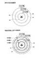
ここで、図4は前記S9において走行可能範囲が表示された液晶ディスプレイ15の表示画面の一例を示した図である。尚、図4では充電時間として10分、20分、30分の3種類の走行可能範囲を示している。
図4に示すように液晶ディスプレイ15の表示画面61には、自車位置周辺の地図画像62と、地図上にマッチングされた自車の現在位置を示す自車位置マーク63と、自車位置マーク63の周囲に等高線状に表示された3種類の走行可能範囲64〜66と、各走行可能範囲に対応する充電時間を示す充電時間表示部67〜69とが表示される。ここで、走行可能範囲64〜66は等高線状に配置された境界線によってその範囲を示しており、その境界線上が各充電時間で到達可能な最長の到達可能地点となる。そして、ユーザは走行可能範囲64〜66を参照することにより、各充電時間で充電後のバッテリに蓄えられている電力が無くなるまでに車両が走行できる範囲を容易に把握することが可能となる。Here, FIG. 4 is a diagram showing an example of a display screen of the
As shown in FIG. 4, the
また、充電時間の異なる複数の走行可能範囲を同時に表示することにより、地図画像62上にユーザの目的地がある場合には、目的地まで走行するのに最低限必要となる充電時間をユーザが容易に把握可能となる。具体的には、図4に示す地点Aがユーザの目的地である場合には、バッテリ7を少なくとも20分充電すれば目的地に到達可能であることが把握できる。また、図4に示す地点Bがユーザの目的地である場合には、バッテリ7を少なくとも30分充電すれば目的地に到達可能であることが把握できる。従って、ユーザは液晶ディスプレイ15を参照することによって、長時間の充電を行うことなく、必要最低限の充電のみ行い、地点A及び地点Bまで走行することが可能となる。尚、上記S9が走行可能範囲表示手段の処理に相当する。 In addition, by simultaneously displaying a plurality of travelable ranges with different charging times, when there is a user's destination on the
尚、図4では走行可能範囲64〜66は等高線状の境界線を用いて示しているが、各エリアを色分けすることにより走行可能範囲64〜66を示しても良い。更に、図4では車両の現在位置から片道での走行可能範囲を表示しているが、ユーザが行う設定に基づいて往復での走行可能範囲を表示するようにしても良い。 In FIG. 4, the travelable ranges 64 to 66 are shown using contour lines, but the travelable ranges 64 to 66 may be shown by color-coding each area. Furthermore, in FIG. 4, the one-way travelable range is displayed from the current position of the vehicle, but the reciprocable travelable range may be displayed based on the setting made by the user.
また、本実施形態の変形例として、前記S8の処理において算出された走行可能範囲を縮小する走行可能範囲縮小処理を行い、前記S9の処理では縮小された走行可能範囲を表示するようにしても良い。
ここで、図5は走行可能範囲縮小処理により縮小された走行可能範囲64〜66を示した模式図である。図5に示す実施形態では、一旦算出された充電時間10分の走行可能範囲64を10%縮小し、充電時間20分の走行可能範囲65を20%縮小し、充電時間30分の走行可能範囲66を30%縮小する。これは、走行可能範囲の算出結果に誤差が生じるのが避けられないことを考慮して、充電後のバッテリ7の残容量で確実に走行することが可能な範囲まで走行可能範囲64〜66を縮小するものである。従って、縮小された走行可能範囲64〜66を基準とすれば、車両の目的地までの走行中にバッテリ7の残量が足りなくなる虞が無い。また、充電時間が長い走行可能範囲、即ち広い走行可能範囲ほど算出結果の誤差が大きくなることを考慮し、充電時間が長い走行可能範囲ほど縮小率を高くすることにより、より確実に走行することが可能な走行可能範囲64〜66を表示することができる。
また、正確な走行可能範囲を算出する為には多数の情報や複雑な計算処理が必要となるが、走行可能範囲を縮小することによって制御部の処理負担を軽減しつつも、車両が確実に到達可能な走行可能範囲を特定できる。As a modification of the present embodiment, a travelable range reduction process for reducing the travelable range calculated in the process of S8 is performed, and the reduced travelable range is displayed in the process of S9. good.
Here, FIG. 5 is a schematic diagram showing the travelable ranges 64-66 reduced by the travelable range reduction process. In the embodiment shown in FIG. 5, the travelable range 64 once calculated for the charging time of 10 minutes is reduced by 10%, the travelable range 65 for the charging time of 20 minutes is reduced by 20%, and the travelable range of the charging time of 30 minutes is reduced. Reduce 66 by 30%. In consideration of the fact that it is inevitable that an error occurs in the calculation result of the travelable range, the travelable ranges 64 to 66 are reduced to a range where the travel can be performed reliably with the remaining capacity of the
In addition, a large amount of information and complicated calculation processing are required to calculate the accurate driving range, but the vehicle can be surely reduced while reducing the processing load of the control unit by reducing the driving range. The reachable travelable range can be specified.
更に、他の変形例として、前記S9の処理で液晶ディスプレイ15に走行可能範囲64〜66が表示された後に、ユーザが施設のジャンルを操作部34で選択することにより、ナビゲーションECU33は走行可能範囲内に位置する選択されたジャンルの施設を液晶ディスプレイ15に表示する施設表示処理を実行するようにしても良い。
ここで、図6はユーザにより施設のジャンルとしてスーパーマーケットが選択された場合に表示される各施設71〜75を示した模式図である。図6に示す実施形態では、ナビゲーションECU33により、A店〜E店の5箇所のスーパーマーケットが走行可能範囲64〜66内に位置すること検索され、各施設の位置が液晶ディスプレイ15に対して表示される。そして、ユーザは液晶ディスプレイ15に表示された各施設と走行可能範囲64〜66を参照することにより、各施設に到達する為に必要な充電時間を容易に把握できる。それにより、例えばB店よりA店の方が購入希望商品の価格が安い場合に、充電に30分かけてA店まで行くのか、価格が高くても充電時間が10分で済むB店に行くのかをユーザに選択させることが可能となる。
尚、ユーザに選択されたジャンルの施設を新たに液晶ディスプレイ15に表示するのではなく、予め液晶ディスプレイ15上に表示されている施設の内、ユーザに選択されたジャンルの施設を強調(例えば、表示色の変更、点滅表示)して表示するようにしても良い。更に、前記した走行可能範囲縮小処理を組合せて適用しても良い。Furthermore, as another modification, after the travelable range 64 to 66 is displayed on the
Here, FIG. 6 is a schematic diagram showing the
The facility of the genre selected by the user is not newly displayed on the
以上詳細に説明した通り、本実施形態に係るナビゲーション装置1、ナビゲーション装置1による地図表示方法及びナビゲーション装置1で実行されるコンピュータプログラムでは、エンジン4と駆動モータ5とを併用するハイブリッド車両における現在のバッテリ7のSOC値、車両周辺の道路形状や勾配情報、交通情報、学習情報等を取得し(S1〜S7)、取得した各情報に基づいてバッテリ7への複数種類の充電時間毎に充電後の車両の走行可能範囲64〜66を算出し(S8)、算出された複数の走行可能範囲64〜66を同時に液晶ディスプレイ15に表示する(S9)ので、ユーザに煩雑且つ長時間の操作を強いることなく、目的地まで走行するのに最低限必要となる充電時間をユーザが容易に把握可能に表示することが可能であり、ユーザに必要以上のバッテリの充電を行わせることもない。従って、ユーザの利便性を向上させることが可能となる。
また、道路の勾配、渋滞情報、交通規制、運転者の操作特性等を考慮して車両の走行可能範囲をより正確に算出するので、目的地まで走行するのに最低限必要となる充電時間をユーザにより正確に報知することが可能である。As described above in detail, in the
In addition, the vehicle travel range is calculated more accurately in consideration of road gradient, traffic jam information, traffic regulations, driver operation characteristics, etc., so the minimum charging time required to travel to the destination It is possible to notify the user accurately.
尚、本発明は前記実施形態に限定されるものではなく、本発明の要旨を逸脱しない範囲内で種々の改良、変形が可能であることは勿論である。
例えば、本実施形態ではハイブリッド車両に搭載されたナビゲーション装置により走行可能範囲64〜66の算出及び表示を行うこととしているが、走行可能範囲64〜66の算出処理については車両と双方向通信可能にある情報センタで実行し、車両はその算出結果を受信してディスプレイに表示するようにしても良い。Note that the present invention is not limited to the above-described embodiment, and various improvements and modifications can be made without departing from the scope of the present invention.
For example, in the present embodiment, the travelable range 64 to 66 is calculated and displayed by the navigation device mounted on the hybrid vehicle. However, the calculation process of the travelable range 64 to 66 can be bidirectionally communicated with the vehicle. It may be executed in a certain information center, and the vehicle may receive the calculation result and display it on the display.
また、走行可能範囲64〜66の算出及び表示処理において、現在のバッテリの残容量が0でない場合には、充電を行わない現在のバッテリの残容量で走行可能な範囲についても算出及び表示処理を行うようにしても良い。 In the calculation and display processing of the travelable ranges 64 to 66, when the current remaining battery capacity is not 0, the calculation and display processing is also performed for the travelable range with the current remaining battery capacity that is not charged. You may make it do.
また、上記実施形態では本願発明をモータとエンジンを併用して駆動源とするハイブリッド車両に適用した場合を説明したが、モータのみを駆動源とする電気自動車にも適用可能である。 Moreover, although the case where this invention was applied to the hybrid vehicle which uses a motor and an engine together as a drive source was demonstrated in the said embodiment, it is applicable also to the electric vehicle which uses only a motor as a drive source.
1 ナビゲーション装置
2 車両
3 電動車両制御システム
4 エンジン
5 駆動モータ
15 液晶ディスプレイ
16 スピーカ
33 ナビゲーションECU
46 車両操作履歴DB
47 地図情報DB
DESCRIPTION OF
46 Vehicle operation history DB
47 Map information DB
Claims (9)
Translated fromJapanese車両に駆動力を発生させるモータに電力を供給するバッテリの残容量を取得するバッテリ残量取得手段と、
前記バッテリ残量取得手段により取得されたバッテリの残容量に基づいて、前記バッテリへの複数種類の充電時間毎に充電後の前記車両の走行可能範囲を算出する走行可能範囲算出手段と、
前記走行可能範囲算出手段によって算出された複数の走行可能範囲を同時に前記表示手段に表示する走行可能範囲表示手段と、を有することを特徴とする地図表示装置。Display means for displaying a map around the vehicle;
Battery remaining amount acquisition means for acquiring a remaining capacity of a battery that supplies electric power to a motor that generates driving force for the vehicle;
Based on the remaining capacity of the battery acquired by the battery remaining amount acquiring unit, a travelable range calculating unit that calculates a travelable range of the vehicle after charging for each of a plurality of types of charging time to the battery;
A map display device comprising: a travelable range display means for simultaneously displaying a plurality of travelable ranges calculated by the travelable range calculation means on the display means.
前記走行可能範囲算出手段は前記道路の勾配に基づいて充電後の前記車両の走行可能範囲を算出することを特徴とする請求項1に記載の地図表示装置。It has a gradient information acquisition means for acquiring information about the gradient of the road,
The map display device according to claim 1, wherein the travelable range calculation unit calculates a travelable range of the vehicle after charging based on a gradient of the road.
前記走行可能範囲算出手段は前記交通情報に基づいて充電後の前記車両の走行可能範囲を算出することを特徴とする請求項1に記載の地図表示装置。Having traffic information acquisition means for acquiring traffic information;
The map display device according to claim 1, wherein the travelable range calculation unit calculates a travelable range of the vehicle after charging based on the traffic information.
前記走行可能範囲算出手段は前記運転者の過去の車両操作に基づいて充電後の前記車両の走行可能範囲を算出することを特徴とする請求項1に記載の地図表示装置。Vehicle operation history storage means for storing the driver's past vehicle operations;
The map display device according to claim 1, wherein the travelable range calculation unit calculates a travelable range of the vehicle after charging based on past vehicle operations of the driver.
前記走行可能範囲表示手段は前記縮小手段により縮小された走行可能範囲を前記表示手段に表示することを特徴とする請求項1乃至請求項4のいずれかに記載の地図表示装置。Reduction means for reducing the travelable range calculated by the travelable range calculation means;
5. The map display device according to claim 1, wherein the travelable range display means displays the travelable range reduced by the reduction means on the display means.
前記ジャンル選択手段によって選択されたジャンルに属するとともに前記走行可能範囲算出手段によって算出された走行可能範囲内に位置する施設を前記表示手段に表示する施設表示手段と、を有することを特徴とする請求項1乃至請求項6のいずれかに記載の地図表示装置。Genre selection means for selecting the genre of the facility,
A facility display means for displaying on the display means a facility that belongs to the genre selected by the genre selection means and is located within the travelable range calculated by the travelable range calculation means. The map display apparatus in any one of Claim 1 thru | or 6.
車両に駆動力を発生させるモータに電力を供給するバッテリの残容量を取得するバッテリ残量取得ステップと、
前記バッテリ残量取得ステップで取得されたバッテリの残容量に基づいて、前記バッテリへの複数種類の充電時間毎に充電後の前記車両の走行可能範囲を算出する走行可能範囲算出ステップと、
前記走行可能範囲算出ステップによって算出された複数の走行可能範囲を同時に前記表示装置に表示する走行可能範囲表示ステップと、を有することを特徴とする地図表示方法。A map display step for displaying a map around the vehicle on the display device;
A battery remaining amount acquiring step for acquiring a remaining capacity of a battery that supplies electric power to a motor that generates driving force for the vehicle;
Based on the remaining capacity of the battery acquired in the battery remaining amount acquisition step, a travelable range calculation step of calculating a travelable range of the vehicle after charging for each of a plurality of types of charging time to the battery;
A map display method comprising: a driving range display step for simultaneously displaying a plurality of driving ranges calculated in the driving range calculation step on the display device.
表示装置に車両周辺の地図を表示する地図表示機能と、
車両に駆動力を発生させるモータに電力を供給するバッテリの残容量を取得するバッテリ残量取得機能と、
前記バッテリ残量取得機能により取得されたバッテリの残容量に基づいて、前記バッテリへの複数種類の充電時間毎に充電後の前記車両の走行可能範囲を算出する走行可能範囲算出機能と、
前記走行可能範囲算出機能によって算出された複数の走行可能範囲を同時に前記表示装置に表示する走行可能範囲表示機能と、
を実行させることを特徴とするコンピュータプログラム。
On the computer,
A map display function for displaying a map around the vehicle on the display device;
A remaining battery capacity acquisition function for acquiring a remaining capacity of a battery that supplies electric power to a motor that generates driving force for the vehicle;
Based on the remaining capacity of the battery acquired by the battery remaining capacity acquisition function, a travelable range calculation function that calculates the travelable range of the vehicle after charging for each of a plurality of types of charging time to the battery;
A driving range display function for simultaneously displaying a plurality of driving ranges calculated by the driving range calculation function on the display device;
A computer program for executing
Priority Applications (5)
| Application Number | Priority Date | Filing Date | Title |
|---|---|---|---|
| JP2007188090AJP4906164B2 (en) | 2007-07-19 | 2007-07-19 | Map display device, map display method, and computer program |
| PCT/JP2008/062937WO2009011393A1 (en) | 2007-07-19 | 2008-07-17 | Map display device, map display method, and computer readable tangible medium |
| EP08791291.1AEP2172740B1 (en) | 2007-07-19 | 2008-07-17 | Map display device, map display method, and computer readable tangible medium |
| CN2008800253243ACN101765756B (en) | 2007-07-19 | 2008-07-17 | Map display device, map display method, and computer readable tangible medium |
| US12/452,618US8417401B2 (en) | 2007-07-19 | 2008-07-17 | Map display apparatus, map display method, and computer-readable tangible medium |
Applications Claiming Priority (1)
| Application Number | Priority Date | Filing Date | Title |
|---|---|---|---|
| JP2007188090AJP4906164B2 (en) | 2007-07-19 | 2007-07-19 | Map display device, map display method, and computer program |
Publications (2)
| Publication Number | Publication Date |
|---|---|
| JP2009025128Atrue JP2009025128A (en) | 2009-02-05 |
| JP4906164B2 JP4906164B2 (en) | 2012-03-28 |
Family
ID=40259725
Family Applications (1)
| Application Number | Title | Priority Date | Filing Date |
|---|---|---|---|
| JP2007188090AExpired - Fee RelatedJP4906164B2 (en) | 2007-07-19 | 2007-07-19 | Map display device, map display method, and computer program |
Country Status (5)
| Country | Link |
|---|---|
| US (1) | US8417401B2 (en) |
| EP (1) | EP2172740B1 (en) |
| JP (1) | JP4906164B2 (en) |
| CN (1) | CN101765756B (en) |
| WO (1) | WO2009011393A1 (en) |
Cited By (33)
| Publication number | Priority date | Publication date | Assignee | Title |
|---|---|---|---|---|
| WO2010119327A1 (en)* | 2009-04-15 | 2010-10-21 | Nissan Motor Co., Ltd. | Electric vehicle structure |
| JP2010252449A (en)* | 2009-04-13 | 2010-11-04 | Denso Corp | Charge monitor apparatus, electric vehicle, and server |
| JP2011147283A (en)* | 2010-01-15 | 2011-07-28 | Alpine Electronics Inc | Charging support system |
| WO2011092854A1 (en)* | 2010-01-29 | 2011-08-04 | パイオニア株式会社 | Information provision device, information processing device, information provision method, information acquisition method, information provision program, information acquisition program, and recording medium |
| WO2011114486A1 (en)* | 2010-03-18 | 2011-09-22 | トヨタ自動車株式会社 | Electrically driven vehicle |
| EP2372307A2 (en) | 2010-03-31 | 2011-10-05 | Aisin Aw Co., Ltd. | Vehicular travel guidance device, vehicular travel guidance method, and computer program |
| JP2011217509A (en)* | 2010-03-31 | 2011-10-27 | Nissan Motor Co Ltd | Display for electric vehicle and display method |
| WO2012098660A1 (en)* | 2011-01-20 | 2012-07-26 | 三菱電機株式会社 | Navigation device and charging control device for electric vehicle |
| WO2012114381A1 (en)* | 2011-02-24 | 2012-08-30 | 三菱電機株式会社 | Map display device, navigation device and map display method |
| JP2012181099A (en)* | 2011-03-01 | 2012-09-20 | Mitsubishi Electric Corp | Energy supply information acquisition device |
| KR101188066B1 (en) | 2010-12-15 | 2012-10-05 | 이경목 | The methode of showing the travelable distance information of the battery vehicle on the samrt phone's map |
| WO2013011880A1 (en)* | 2011-07-20 | 2013-01-24 | トヨタ自動車株式会社 | Drive assist apparatus |
| JP2013083604A (en)* | 2011-10-12 | 2013-05-09 | Toyota Motor Corp | Information providing device |
| WO2013084931A1 (en) | 2011-12-08 | 2013-06-13 | 日立オートモティブシステムズ株式会社 | Device, method and program for calculating accessible range |
| EP2664484A2 (en) | 2012-03-08 | 2013-11-20 | Hitachi Automotive Systems, Ltd. | Traveling range calculation apparatus, method and program |
| WO2014002205A1 (en)* | 2012-06-27 | 2014-01-03 | 三菱電機株式会社 | Charging control device for electric vehicle |
| WO2014132553A1 (en)* | 2013-02-26 | 2014-09-04 | 株式会社デンソー | Travel guide device for electric vehicles |
| CN104203705A (en)* | 2011-12-28 | 2014-12-10 | 丰田自动车工程及制造北美公司 | Intelligent range map for an electric vehicle |
| EP2949501A1 (en) | 2014-05-26 | 2015-12-02 | Hitachi Ltd. | Central apparatus, driving support system, and driving support method |
| JP2016027347A (en)* | 2015-10-29 | 2016-02-18 | パイオニア株式会社 | Image processing apparatus, image processing management apparatus, terminal device, and image processing method |
| JP2016516188A (en)* | 2013-03-15 | 2016-06-02 | アバルタ テクノロジーズ、 インク.Abalta Technologies, Inc. | Predicting vehicle travel distance |
| WO2016199215A1 (en)* | 2015-06-09 | 2016-12-15 | 日産自動車株式会社 | Vehicle arrival area presentation device and vehicle arrival area presentation method |
| KR101774595B1 (en)* | 2011-11-21 | 2017-09-04 | 현대자동차주식회사 | Device for displaying driving range in the electric vehicle and the method thereof |
| US9759572B2 (en) | 2012-11-06 | 2017-09-12 | Mitsubishi Electric Corporation | Navigation apparatus that calculates one or more travelable ranges for an electric vehicle |
| JP2018066759A (en)* | 2018-01-17 | 2018-04-26 | 三菱電機株式会社 | Cruising range output device, map display device, and cruising range output method |
| KR101865928B1 (en)* | 2011-11-08 | 2018-07-04 | 현대자동차주식회사 | Method for informing driving boundary of an electric vehicle |
| JP2018109631A (en)* | 2018-01-16 | 2018-07-12 | パイオニア株式会社 | Image processing unit, image processing management device, terminal device, and image processing method |
| US10222222B2 (en) | 2013-03-15 | 2019-03-05 | Abalta Technologies, Inc. | Roundtrip range projection |
| JP2019095310A (en)* | 2017-11-24 | 2019-06-20 | マツダ株式会社 | Information providing device for vehicles |
| JP2019211484A (en)* | 2019-08-02 | 2019-12-12 | パイオニア株式会社 | Image processing apparatus, image processing management apparatus, terminal device, and image processing method |
| US10514266B2 (en) | 2017-09-13 | 2019-12-24 | Hyundai Motor Company | Method and system for displaying distance to empty of vehicle |
| JP2021071806A (en)* | 2019-10-29 | 2021-05-06 | トヨタ自動車株式会社 | Information processing device, information processing method, and information processing program |
| JP2023148605A (en)* | 2022-03-30 | 2023-10-13 | 本田技研工業株式会社 | simulation device |
Families Citing this family (89)
| Publication number | Priority date | Publication date | Assignee | Title |
|---|---|---|---|---|
| JP4591395B2 (en)* | 2006-03-31 | 2010-12-01 | アイシン・エィ・ダブリュ株式会社 | Navigation system |
| JP4434258B2 (en)* | 2007-10-30 | 2010-03-17 | 株式会社デンソー | Weather information notification device and program for weather information notification device |
| DE102008030563B4 (en) | 2008-06-27 | 2023-11-09 | Bayerische Motoren Werke Aktiengesellschaft | motor vehicle |
| US10189359B2 (en)* | 2009-02-17 | 2019-01-29 | Chargepoint, Inc. | Transmitting notification messages for an electric vehicle charging network |
| DE102010021343A1 (en)* | 2009-09-04 | 2011-03-10 | Volkswagen Ag | Method and device for providing information in a vehicle |
| US20110130885A1 (en)* | 2009-12-01 | 2011-06-02 | Bowen Donald J | Method and system for managing the provisioning of energy to or from a mobile energy storage device |
| JP5482280B2 (en)* | 2010-02-18 | 2014-05-07 | ソニー株式会社 | Information processing apparatus, electric vehicle, and discharge management method |
| JP5577717B2 (en) | 2010-01-25 | 2014-08-27 | ソニー株式会社 | How to manage power efficiently |
| DE102010010445A1 (en)* | 2010-02-25 | 2011-08-25 | Dr. Ing. h.c. F. Porsche Aktiengesellschaft, 70435 | Display device of a motor vehicle |
| JP5141705B2 (en)* | 2010-03-19 | 2013-02-13 | アイシン・エィ・ダブリュ株式会社 | Driving support apparatus, method and program |
| JP5771902B2 (en)* | 2010-04-14 | 2015-09-02 | ソニー株式会社 | Route guidance device, route guidance method and computer program |
| DE102010015342A1 (en)* | 2010-04-17 | 2011-10-20 | Albrecht Kretzschmar | Energy navigation map for e.g. hybrid vehicle, has gradient values measured and/or calculated along route and driving direction, where gradient values and sum value are utilized to display energy- and consumption-optimized routing |
| US20110258047A1 (en)* | 2010-04-19 | 2011-10-20 | Microsoft Corporation | Incorporating time and spatial relationships between user/advertiser locations into advertisement relevance |
| JP5370585B2 (en)* | 2010-04-19 | 2013-12-18 | 日産自動車株式会社 | Information providing apparatus and information providing method |
| AT507916B1 (en) | 2010-04-29 | 2012-01-15 | Avl List Gmbh | METHOD FOR OPERATING AN ELECTRIC VEHICLE |
| FR2960504B1 (en)* | 2010-05-31 | 2012-08-17 | Peugeot Citroen Automobiles Sa | DEVICE FOR PROVIDING INFORMATION RELATING TO THE AUTONOMY OF A TERRESTRIAL VEHICLE |
| JP5742117B2 (en)* | 2010-06-03 | 2015-07-01 | 日産自動車株式会社 | Information presentation device for vehicle |
| AT508065B1 (en) | 2010-06-24 | 2012-09-15 | Avl List Gmbh | METHOD FOR OPERATING AN ELECTRIC VEHICLE |
| KR101202336B1 (en)* | 2010-07-28 | 2012-11-16 | 삼성에스디아이 주식회사 | Electric vehicle and control method |
| US8754777B1 (en)* | 2010-08-13 | 2014-06-17 | Google Inc. | System and method for predicting user route and destination |
| US9385531B2 (en)* | 2010-08-24 | 2016-07-05 | Bennett Hill Branscomb | System and method for optimizing returns of power feedstock producers |
| KR101262459B1 (en)* | 2010-10-12 | 2013-05-08 | 기아자동차주식회사 | Telematics unit for remote charging control and service providing method of the same |
| US9043134B2 (en)* | 2010-11-09 | 2015-05-26 | Toyota Motor Engineering & Manufacturing North America, Inc. | Range marker for a navigation system |
| CN103221786B (en)* | 2010-11-18 | 2016-07-27 | 奥迪股份公司 | Calculate range and/or consumption with energy costs assigned to area segments |
| DE102011104258A1 (en)* | 2010-11-19 | 2012-05-24 | Audi Ag | Method for determining a partial area of a map and motor vehicle describing the remaining range of a motor vehicle |
| US20120143410A1 (en)* | 2010-12-01 | 2012-06-07 | Aptera Motors, Inc. | Interactive driver system for an electric vehicle |
| EP2465721A1 (en)* | 2010-12-16 | 2012-06-20 | Alcatel Lucent | System and methods for predicting energy requirements of a plurality of electric energy vehicles |
| JP5656624B2 (en)* | 2010-12-28 | 2015-01-21 | 三菱重工業株式会社 | Road traffic flow simulation apparatus, road traffic flow simulation program, and road traffic flow simulation method |
| US8755994B2 (en)* | 2011-01-06 | 2014-06-17 | Ford Global Technologies, Llc | Information display system and method |
| US10421420B2 (en)* | 2011-01-06 | 2019-09-24 | Ford Global Technologies, Llc | Methods and apparatus for reporting state of charge in electric vehicles |
| FR2970823A1 (en)* | 2011-01-26 | 2012-07-27 | Peugeot Citroen Automobiles Sa | Electric battery e.g. main battery, recharging controlling device for use in charger of e.g. hybrid car, has processing unit for determining recharging parameters based on charging states and storage capacities of batteries |
| CN103339664B (en)* | 2011-02-03 | 2015-07-29 | 日本电气株式会社 | Charger arrangement plan supportive device, charger arrangement plan support method |
| EP2693168B1 (en)* | 2011-03-29 | 2020-12-16 | Clarion Co., Ltd. | Navigation device, travelable distance display system |
| DE102011015777A1 (en) | 2011-04-01 | 2012-10-04 | Volkswagen Aktiengesellschaft | Method and apparatus for carrying out itinerary planning for a vehicle |
| US10065628B2 (en)* | 2011-05-09 | 2018-09-04 | Ford Global Technologies, Llc | Location enhanced distance until charge (DUC) estimation for a plug-in hybrid electric vehicle (PHEV) |
| FR2976693B1 (en) | 2011-06-14 | 2016-07-01 | Commissariat Energie Atomique | METHOD FOR MANAGING ENERGY IN AN ELECTRICALLY ASSISTED VEHICLE |
| DE102011104153A1 (en) | 2011-06-14 | 2012-12-20 | Continental Automotive Gmbh | Method for displaying the range of a vehicle with electric drive and display device |
| US20130009765A1 (en)* | 2011-07-06 | 2013-01-10 | Ford Global Technologies, Llc | Methods and systems for determining a range limit based on a vehicle's energy source status |
| DE102011108381B4 (en)* | 2011-07-22 | 2013-02-21 | Audi Ag | A method of assisting a person in planning a trip with an electric vehicle and motor vehicle having a navigation device |
| TWI584976B (en)* | 2011-07-26 | 2017-06-01 | 睿能創意公司 | Dynamically limiting vehicle operation for best effort economy |
| US20130052490A1 (en)* | 2011-08-23 | 2013-02-28 | Coda Automotive, Inc. | Environmental control using a dynamic temperature set point |
| JP5853499B2 (en)* | 2011-08-31 | 2016-02-09 | 日産自動車株式会社 | Traveling area display device |
| US8589076B2 (en)* | 2011-09-14 | 2013-11-19 | International Business Machines Corporation | Power usage planning for a vehicle |
| US8874367B2 (en)* | 2011-10-14 | 2014-10-28 | Equilateral Technologies, Inc. | Method for estimating and displaying range of a vehicle |
| DE102011084633A1 (en)* | 2011-10-17 | 2013-04-18 | Robert Bosch Gmbh | Device for detecting defects in track data i.e. operating mode of vehicle component of vehicle, has checker checking whether operating condition of vehicle position corresponding to feedback data with respect to track data |
| US8874293B2 (en)* | 2011-12-30 | 2014-10-28 | Ford Global Technologies, Llc | Climate control advisory system and method |
| CN103292820B (en)* | 2012-03-01 | 2016-08-17 | 日立(中国)研究开发有限公司 | Provide a user with equipment and the method for the accurately continuation of the journey scope of moving body |
| JP6035917B2 (en) | 2012-07-05 | 2016-11-30 | 日産自動車株式会社 | Vehicle information providing device |
| JP5929602B2 (en)* | 2012-08-02 | 2016-06-08 | 株式会社デンソー | Navigation device |
| CN103017769A (en)* | 2012-11-27 | 2013-04-03 | 北京世纪高通科技有限公司 | Method and device for calculating driving range of electric automobile |
| TWI479772B (en)* | 2013-02-21 | 2015-04-01 | 台達電子工業股份有限公司 | Charging system for electric vehicle and charging method thereof |
| US9121356B2 (en) | 2013-02-21 | 2015-09-01 | Ford Global Technologies, Llc | Stop/start control to increase microhybrid vehicle battery charge |
| US9926881B2 (en) | 2013-03-11 | 2018-03-27 | Ford Global Technologies Llc | Stop/start control for stop/start vehicle in turn lane |
| CN108189701B (en) | 2013-08-06 | 2021-10-22 | 睿能创意公司 | Regulation of electric vehicle systems based on electrical energy storage device thermal profiles |
| US9132746B2 (en) | 2013-08-15 | 2015-09-15 | Honda Motor Co., Ltd. | Method and system for reducing range anxiety |
| HUP1300489A2 (en)* | 2013-08-15 | 2015-03-02 | Gps Tuner Kft | Method for displaying real range of an electric vehicle |
| US9151631B2 (en)* | 2013-10-14 | 2015-10-06 | Ford Global Technologies, Llc | Vehicle fueling route planning |
| JP6081902B2 (en)* | 2013-10-31 | 2017-02-15 | 三菱重工業株式会社 | Travel route guidance device, travel route guidance system, travel route guidance method, and program |
| US9488493B2 (en)* | 2014-01-16 | 2016-11-08 | Ford Global Technologies, Llc | Method and apparatus for electric vehicle trip and recharge planning |
| KR101655609B1 (en)* | 2014-12-11 | 2016-09-07 | 현대자동차주식회사 | Method for controlling battery state of charge in hybrid electric vehicle |
| US10030987B2 (en)* | 2015-02-05 | 2018-07-24 | Volkswagen Ag | System and methodologies for visual relevancy-grading of a navigation map |
| CN107873006B (en) | 2015-06-05 | 2021-02-02 | 睿能创意公司 | Vehicle and method for determining a specific type of load of an electric vehicle |
| EP3112809A1 (en)* | 2015-07-03 | 2017-01-04 | Seat, S.A. | Method for the presentation of information relating to locations of points of interest |
| ITUB20155621A1 (en)* | 2015-11-16 | 2017-05-16 | Piaggio & C Spa | Method of managing the energy autonomy of an electric pedal assisted bicycle |
| KR101755504B1 (en) | 2016-04-01 | 2017-07-07 | 현대자동차 주식회사 | Server of providing battery display state of electric vehicle, device and computer readable recording medium for setting battery display state of electric vehicle |
| GB201608233D0 (en)* | 2016-05-04 | 2016-06-22 | Tomtom Navigation Bv | Methods and systems for determining safe return range |
| KR20180056068A (en)* | 2016-11-18 | 2018-05-28 | 삼성전자주식회사 | Electronic device and method for controlling unmanned aerial vehicle |
| US20190003841A1 (en)* | 2017-06-30 | 2019-01-03 | MediaAgility Inc | Method and system for evolving a context cognitive cartographic grid for a map |
| JP6597752B2 (en)* | 2017-11-01 | 2019-10-30 | マツダ株式会社 | Vehicle display device |
| CN109885043A (en)* | 2017-12-06 | 2019-06-14 | 田瑜 | Electric water sports equipment and monitoring system |
| US10458349B2 (en)* | 2017-12-13 | 2019-10-29 | GM Global Technology Operations LLC | Method of start/stop engine control based on location information |
| CN110334287A (en)* | 2018-03-16 | 2019-10-15 | 博世汽车部件(苏州)有限公司 | Method and apparatus for providing navigation information |
| CN108556661B (en)* | 2018-04-23 | 2021-10-22 | 山东理工大学 | A kind of electric vehicle active charging early warning and reservation method |
| DE102018212256A1 (en)* | 2018-07-24 | 2020-01-30 | Robert Bosch Gmbh | Method and device for range estimation for a vehicle |
| CN109186623A (en)* | 2018-09-10 | 2019-01-11 | 威马智慧出行科技(上海)有限公司 | A kind of travelable range dynamic display method and its system |
| CN111016665B (en)* | 2018-10-09 | 2023-04-07 | 沈阳美行科技股份有限公司 | Method and device for determining driving range of electric vehicle |
| JPWO2020100288A1 (en)* | 2018-11-16 | 2021-10-07 | 住友電気工業株式会社 | Charging support systems, methods, and computer programs |
| GB2581786A (en)* | 2019-02-22 | 2020-09-02 | Dyson Technology Ltd | Range prediction |
| US12013243B2 (en) | 2019-04-05 | 2024-06-18 | FLIR Belgium BVBA | Passage planning and navigation systems and methods |
| CN110186473B (en)* | 2019-05-29 | 2023-05-02 | 腾讯科技(深圳)有限公司 | Image processing method, device, electronic equipment and storage medium |
| GB201908502D0 (en)* | 2019-06-13 | 2019-07-31 | Tomtom Telematics Bv | Methods and systems of assigning trips |
| US12018955B2 (en) | 2019-08-14 | 2024-06-25 | Honda Motor Co., Ltd. | System and method for presenting electric vehicle charging options |
| US12117498B2 (en) | 2019-08-14 | 2024-10-15 | Honda Motor Co., Ltd. | System and method for presenting electric vehicle charging options based on a predicted charging speed |
| CN113352938B (en)* | 2020-07-31 | 2022-05-31 | 重庆长安新能源汽车科技有限公司 | Method and system for determining double remaining mileage of pure electric vehicle and pure electric vehicle |
| CN113085655B (en)* | 2021-05-11 | 2022-08-26 | 国网黑龙江省电力有限公司电力科学研究院 | Vehicle-mounted electric automobile comprehensive service system |
| US11840157B2 (en)* | 2021-07-19 | 2023-12-12 | Rivian Ip Holdings, Llc | Charge time estimation |
| US12196566B2 (en) | 2022-10-11 | 2025-01-14 | Signal 4D | Predicting vehicle travel range |
| DE102022127918A1 (en)* | 2022-10-21 | 2024-05-02 | Bayerische Motoren Werke Aktiengesellschaft | Charging a traction battery of an electric vehicle |
| KR20240173277A (en)* | 2023-06-02 | 2024-12-11 | 현대자동차주식회사 | Method for controlling a vehicle by altitude prediction based on identification of high-energy area and vehicle using the same |
Citations (7)
| Publication number | Priority date | Publication date | Assignee | Title |
|---|---|---|---|---|
| JP2000283774A (en)* | 1999-03-31 | 2000-10-13 | Matsushita Electric Ind Co Ltd | Reachable area display device by specifying amount |
| JP2000292195A (en)* | 1999-04-01 | 2000-10-20 | Isuzu Motors Ltd | Hydrogen fuel supply stand guidance system for hydrogen fuel driven motor vehicles |
| JP2001112121A (en)* | 1999-10-07 | 2001-04-20 | Suzuki Motor Corp | Navigation system for electric vehicle |
| JP2001215124A (en)* | 2000-02-03 | 2001-08-10 | Fujitsu Ten Ltd | Navigation device, facility data memory media, and facility data supplying data |
| JP2003294463A (en)* | 2002-04-02 | 2003-10-15 | Nissan Motor Co Ltd | Navigation system of electric automobile |
| JP2004270604A (en)* | 2003-03-11 | 2004-09-30 | Toyota Motor Corp | Vehicle with bi-fuel engine |
| JP2006115623A (en)* | 2004-10-15 | 2006-04-27 | Fuji Heavy Ind Ltd | Travel distance estimation system |
Family Cites Families (10)
| Publication number | Priority date | Publication date | Assignee | Title |
|---|---|---|---|---|
| JP3177806B2 (en) | 1993-09-17 | 2001-06-18 | 本田技研工業株式会社 | Display device for electric vehicle |
| DE4344368C1 (en) | 1993-12-24 | 1995-05-11 | Daimler Benz Ag | Charge information system for an electrical or hybrid vehicle |
| JP3115197B2 (en) | 1994-10-21 | 2000-12-04 | 本田技研工業株式会社 | Automotive display device |
| JPH09233720A (en)* | 1996-02-20 | 1997-09-05 | Sumitomo Electric Ind Ltd | Charging controller |
| JP2843883B2 (en)* | 1996-05-22 | 1999-01-06 | 本田技研工業株式会社 | Control device for hybrid vehicle |
| JP3758140B2 (en)* | 2001-07-09 | 2006-03-22 | 日産自動車株式会社 | Information presentation device |
| JP2005198445A (en) | 2004-01-08 | 2005-07-21 | Yamaha Motor Co Ltd | Charging management system and charging management device |
| JP2006112932A (en)* | 2004-10-15 | 2006-04-27 | Fuji Heavy Ind Ltd | Electric vehicle navigation system |
| US20100094496A1 (en)* | 2008-09-19 | 2010-04-15 | Barak Hershkovitz | System and Method for Operating an Electric Vehicle |
| US8170737B2 (en)* | 2009-04-30 | 2012-05-01 | GM Global Technology Operations LLC | Method of controlling vehicle powertrain and vehicle control system |
- 2007
- 2007-07-19JPJP2007188090Apatent/JP4906164B2/ennot_activeExpired - Fee Related
- 2008
- 2008-07-17USUS12/452,618patent/US8417401B2/ennot_activeExpired - Fee Related
- 2008-07-17CNCN2008800253243Apatent/CN101765756B/ennot_activeExpired - Fee Related
- 2008-07-17EPEP08791291.1Apatent/EP2172740B1/ennot_activeNot-in-force
- 2008-07-17WOPCT/JP2008/062937patent/WO2009011393A1/enactiveApplication Filing
Patent Citations (7)
| Publication number | Priority date | Publication date | Assignee | Title |
|---|---|---|---|---|
| JP2000283774A (en)* | 1999-03-31 | 2000-10-13 | Matsushita Electric Ind Co Ltd | Reachable area display device by specifying amount |
| JP2000292195A (en)* | 1999-04-01 | 2000-10-20 | Isuzu Motors Ltd | Hydrogen fuel supply stand guidance system for hydrogen fuel driven motor vehicles |
| JP2001112121A (en)* | 1999-10-07 | 2001-04-20 | Suzuki Motor Corp | Navigation system for electric vehicle |
| JP2001215124A (en)* | 2000-02-03 | 2001-08-10 | Fujitsu Ten Ltd | Navigation device, facility data memory media, and facility data supplying data |
| JP2003294463A (en)* | 2002-04-02 | 2003-10-15 | Nissan Motor Co Ltd | Navigation system of electric automobile |
| JP2004270604A (en)* | 2003-03-11 | 2004-09-30 | Toyota Motor Corp | Vehicle with bi-fuel engine |
| JP2006115623A (en)* | 2004-10-15 | 2006-04-27 | Fuji Heavy Ind Ltd | Travel distance estimation system |
Cited By (58)
| Publication number | Priority date | Publication date | Assignee | Title |
|---|---|---|---|---|
| JP2010252449A (en)* | 2009-04-13 | 2010-11-04 | Denso Corp | Charge monitor apparatus, electric vehicle, and server |
| US8928279B2 (en) | 2009-04-15 | 2015-01-06 | Nissan Motor Co., Ltd. | Electric vehicle structure |
| WO2010119327A1 (en)* | 2009-04-15 | 2010-10-21 | Nissan Motor Co., Ltd. | Electric vehicle structure |
| JP2011147283A (en)* | 2010-01-15 | 2011-07-28 | Alpine Electronics Inc | Charging support system |
| WO2011092854A1 (en)* | 2010-01-29 | 2011-08-04 | パイオニア株式会社 | Information provision device, information processing device, information provision method, information acquisition method, information provision program, information acquisition program, and recording medium |
| WO2011114486A1 (en)* | 2010-03-18 | 2011-09-22 | トヨタ自動車株式会社 | Electrically driven vehicle |
| US8423219B2 (en) | 2010-03-18 | 2013-04-16 | Toyota Jidosha Kabushiki Kaisha | Electric drive vehicle |
| JPWO2011114486A1 (en)* | 2010-03-18 | 2013-06-27 | トヨタ自動車株式会社 | Electric drive vehicle |
| JP2011217509A (en)* | 2010-03-31 | 2011-10-27 | Nissan Motor Co Ltd | Display for electric vehicle and display method |
| US8872675B2 (en) | 2010-03-31 | 2014-10-28 | Aisin Aw Co., Ltd. | Vehicular travel guidance device, vehicular travel guidance method, and computer program |
| JP2011214894A (en)* | 2010-03-31 | 2011-10-27 | Aisin Aw Co Ltd | Vehicular travel guidance device, vehicular travel guidance method, and computer program |
| EP2372307A2 (en) | 2010-03-31 | 2011-10-05 | Aisin Aw Co., Ltd. | Vehicular travel guidance device, vehicular travel guidance method, and computer program |
| KR101188066B1 (en) | 2010-12-15 | 2012-10-05 | 이경목 | The methode of showing the travelable distance information of the battery vehicle on the samrt phone's map |
| JPWO2012098660A1 (en)* | 2011-01-20 | 2014-06-09 | 三菱電機株式会社 | Navigation device and charging control device for electric vehicle |
| WO2012098660A1 (en)* | 2011-01-20 | 2012-07-26 | 三菱電機株式会社 | Navigation device and charging control device for electric vehicle |
| US9581464B2 (en) | 2011-02-24 | 2017-02-28 | Mitsubishi Electric Corporation | Map display device, navigation device and map display method |
| US9052998B2 (en) | 2011-02-24 | 2015-06-09 | Mitsubishi Electric Corporation | Map display device, navigation device and map display method |
| JPWO2012114381A1 (en)* | 2011-02-24 | 2014-07-07 | 三菱電機株式会社 | Map display device, navigation device, and map display method |
| US10514265B2 (en) | 2011-02-24 | 2019-12-24 | Mitsubishi Electric Corporation | Map display device, navigation device and map display method |
| DE112011104957T5 (en) | 2011-02-24 | 2013-11-28 | Mitsubishi Electric Corporation | Map display device, navigation device and map display method |
| WO2012114381A1 (en)* | 2011-02-24 | 2012-08-30 | 三菱電機株式会社 | Map display device, navigation device and map display method |
| JP2012181099A (en)* | 2011-03-01 | 2012-09-20 | Mitsubishi Electric Corp | Energy supply information acquisition device |
| JP2013024680A (en)* | 2011-07-20 | 2013-02-04 | Toyota Motor Corp | Driving support device |
| US20140163854A1 (en)* | 2011-07-20 | 2014-06-12 | Toyota Jidosha Kabushiki Kaisha | Drive assist apparatus |
| US10232855B2 (en) | 2011-07-20 | 2019-03-19 | Toyota Jidosha Kabushiki Kaisha | Drive assist apparatus |
| US10112620B2 (en) | 2011-07-20 | 2018-10-30 | Toyota Jidosha Kabushiki Kaisha | Drive assist apparatus |
| WO2013011880A1 (en)* | 2011-07-20 | 2013-01-24 | トヨタ自動車株式会社 | Drive assist apparatus |
| JP2013083604A (en)* | 2011-10-12 | 2013-05-09 | Toyota Motor Corp | Information providing device |
| KR101865928B1 (en)* | 2011-11-08 | 2018-07-04 | 현대자동차주식회사 | Method for informing driving boundary of an electric vehicle |
| KR101774595B1 (en)* | 2011-11-21 | 2017-09-04 | 현대자동차주식회사 | Device for displaying driving range in the electric vehicle and the method thereof |
| WO2013084931A1 (en) | 2011-12-08 | 2013-06-13 | 日立オートモティブシステムズ株式会社 | Device, method and program for calculating accessible range |
| US9308827B2 (en) | 2011-12-08 | 2016-04-12 | Hitachi, Ltd. | Reachable range calculation apparatus, method, and program |
| JP2015505452A (en)* | 2011-12-28 | 2015-02-19 | トヨタ モーター エンジニアリング アンド マニュファクチャリング ノース アメリカ,インコーポレイティド | Intelligent range map for electric vehicles |
| CN104203705B (en)* | 2011-12-28 | 2018-09-28 | 丰田自动车工程及制造北美公司 | Smart Range Maps for Electric Vehicles |
| CN104203705A (en)* | 2011-12-28 | 2014-12-10 | 丰田自动车工程及制造北美公司 | Intelligent range map for an electric vehicle |
| EP2664484A2 (en) | 2012-03-08 | 2013-11-20 | Hitachi Automotive Systems, Ltd. | Traveling range calculation apparatus, method and program |
| WO2014002205A1 (en)* | 2012-06-27 | 2014-01-03 | 三菱電機株式会社 | Charging control device for electric vehicle |
| DE112012007108B4 (en) | 2012-11-06 | 2019-06-13 | Mitsubishi Electric Corporation | navigation device |
| US9759572B2 (en) | 2012-11-06 | 2017-09-12 | Mitsubishi Electric Corporation | Navigation apparatus that calculates one or more travelable ranges for an electric vehicle |
| WO2014132553A1 (en)* | 2013-02-26 | 2014-09-04 | 株式会社デンソー | Travel guide device for electric vehicles |
| JP2016516188A (en)* | 2013-03-15 | 2016-06-02 | アバルタ テクノロジーズ、 インク.Abalta Technologies, Inc. | Predicting vehicle travel distance |
| US10151596B2 (en) | 2013-03-15 | 2018-12-11 | Abalta Technologies, Inc. | Caching map data for efficient vehicle range projection |
| US10222222B2 (en) | 2013-03-15 | 2019-03-05 | Abalta Technologies, Inc. | Roundtrip range projection |
| EP2949501A1 (en) | 2014-05-26 | 2015-12-02 | Hitachi Ltd. | Central apparatus, driving support system, and driving support method |
| US11099022B2 (en) | 2015-06-09 | 2021-08-24 | Nissan Motor Co., Ltd. | Vehicle reach area presentation device and vehicle reach area presentation method |
| JPWO2016199215A1 (en)* | 2015-06-09 | 2018-03-29 | 日産自動車株式会社 | Vehicle arrival area presentation device and vehicle arrival area presentation method |
| WO2016199215A1 (en)* | 2015-06-09 | 2016-12-15 | 日産自動車株式会社 | Vehicle arrival area presentation device and vehicle arrival area presentation method |
| US10317228B2 (en) | 2015-06-09 | 2019-06-11 | Nissan Motor Co., Ltd. | Vehicle reach area presentation device and vehicle reach area presentation method |
| JP2016027347A (en)* | 2015-10-29 | 2016-02-18 | パイオニア株式会社 | Image processing apparatus, image processing management apparatus, terminal device, and image processing method |
| US10514266B2 (en) | 2017-09-13 | 2019-12-24 | Hyundai Motor Company | Method and system for displaying distance to empty of vehicle |
| JP2019095310A (en)* | 2017-11-24 | 2019-06-20 | マツダ株式会社 | Information providing device for vehicles |
| JP2018109631A (en)* | 2018-01-16 | 2018-07-12 | パイオニア株式会社 | Image processing unit, image processing management device, terminal device, and image processing method |
| JP2018066759A (en)* | 2018-01-17 | 2018-04-26 | 三菱電機株式会社 | Cruising range output device, map display device, and cruising range output method |
| JP2019211484A (en)* | 2019-08-02 | 2019-12-12 | パイオニア株式会社 | Image processing apparatus, image processing management apparatus, terminal device, and image processing method |
| JP2021071806A (en)* | 2019-10-29 | 2021-05-06 | トヨタ自動車株式会社 | Information processing device, information processing method, and information processing program |
| JP7172948B2 (en) | 2019-10-29 | 2022-11-16 | トヨタ自動車株式会社 | Information processing device, information processing method, and information processing program |
| JP2023148605A (en)* | 2022-03-30 | 2023-10-13 | 本田技研工業株式会社 | simulation device |
| JP7430212B2 (en) | 2022-03-30 | 2024-02-09 | 本田技研工業株式会社 | simulation device |
Also Published As
| Publication number | Publication date |
|---|---|
| EP2172740A4 (en) | 2012-08-22 |
| JP4906164B2 (en) | 2012-03-28 |
| EP2172740A1 (en) | 2010-04-07 |
| US20100138098A1 (en) | 2010-06-03 |
| CN101765756A (en) | 2010-06-30 |
| WO2009011393A1 (en) | 2009-01-22 |
| EP2172740B1 (en) | 2016-04-13 |
| US8417401B2 (en) | 2013-04-09 |
| CN101765756B (en) | 2013-03-27 |
Similar Documents
| Publication | Publication Date | Title |
|---|---|---|
| JP4906164B2 (en) | Map display device, map display method, and computer program | |
| JP4737154B2 (en) | Supply facility guide device, supply facility guide method, and computer program | |
| JP5071018B2 (en) | Vehicle consumption energy estimation device, vehicle consumption energy estimation method, and computer program | |
| JP4946713B2 (en) | Parking position determination device, parking position determination method, and computer program | |
| US8116973B2 (en) | Vehicular display device, method of controlling the same, program, and storage medium having program stored therein | |
| JP5045685B2 (en) | Route guidance device, route guidance method and computer program | |
| US8364388B2 (en) | Traveling guidance system, traveling guidance method, and computer program | |
| JP5029583B2 (en) | Travel guidance device, travel guidance method, and computer program | |
| JP5012754B2 (en) | In-vehicle battery charging support device, in-vehicle battery charging support method, and computer program | |
| CN101516703A (en) | Vehicle control device, vehicle control method, program for causing computer to execute vehicle control method, and recording medium having program recorded thereon | |
| JP5093071B2 (en) | Travel guidance device, travel guidance method, and computer program | |
| JP2010169423A (en) | Driving guidance apparatus, driving guidance method, and computer program | |
| JP2009516829A (en) | Vehicle navigation system | |
| JP2008249503A (en) | Electric vehicle drive control system and electric vehicle drive control method | |
| JP5167968B2 (en) | Hybrid vehicle driving support apparatus, driving support method and program | |
| JP6020285B2 (en) | Driving support system, driving support method, and computer program | |
| JP5370219B2 (en) | In-vehicle battery charging support device, in-vehicle battery charging support method, and computer program | |
| JP4692521B2 (en) | Vehicle control apparatus, vehicle control method, and computer program | |
| JP2013072804A (en) | Electric vehicle | |
| JP2009196449A (en) | Travel controller and travel control method for hybrid vehicle, and program | |
| JP5347991B2 (en) | Vehicle travel guidance device, vehicle travel guidance method, and computer program | |
| JP2008230415A (en) | Electric vehicle drive control system and method |
Legal Events
| Date | Code | Title | Description |
|---|---|---|---|
| A621 | Written request for application examination | Free format text:JAPANESE INTERMEDIATE CODE: A621 Effective date:20090421 | |
| RD03 | Notification of appointment of power of attorney | Free format text:JAPANESE INTERMEDIATE CODE: A7423 Effective date:20090421 | |
| A521 | Request for written amendment filed | Free format text:JAPANESE INTERMEDIATE CODE: A821 Effective date:20090421 | |
| A131 | Notification of reasons for refusal | Free format text:JAPANESE INTERMEDIATE CODE: A131 Effective date:20110705 | |
| A521 | Request for written amendment filed | Free format text:JAPANESE INTERMEDIATE CODE: A523 Effective date:20110830 | |
| TRDD | Decision of grant or rejection written | ||
| A01 | Written decision to grant a patent or to grant a registration (utility model) | Free format text:JAPANESE INTERMEDIATE CODE: A01 Effective date:20111220 | |
| A01 | Written decision to grant a patent or to grant a registration (utility model) | Free format text:JAPANESE INTERMEDIATE CODE: A01 | |
| A61 | First payment of annual fees (during grant procedure) | Free format text:JAPANESE INTERMEDIATE CODE: A61 Effective date:20120109 | |
| FPAY | Renewal fee payment (event date is renewal date of database) | Free format text:PAYMENT UNTIL: 20150120 Year of fee payment:3 | |
| R150 | Certificate of patent or registration of utility model | Ref document number:4906164 Country of ref document:JP Free format text:JAPANESE INTERMEDIATE CODE: R150 Free format text:JAPANESE INTERMEDIATE CODE: R150 | |
| R250 | Receipt of annual fees | Free format text:JAPANESE INTERMEDIATE CODE: R250 | |
| LAPS | Cancellation because of no payment of annual fees |