JP2009020293A - Display and viewing angle control device used therefor - Google Patents
Display and viewing angle control device used thereforDownload PDFInfo
- Publication number
- JP2009020293A JP2009020293AJP2007182533AJP2007182533AJP2009020293AJP 2009020293 AJP2009020293 AJP 2009020293AJP 2007182533 AJP2007182533 AJP 2007182533AJP 2007182533 AJP2007182533 AJP 2007182533AJP 2009020293 AJP2009020293 AJP 2009020293A
- Authority
- JP
- Japan
- Prior art keywords
- liquid crystal
- viewing angle
- display
- translucent
- electrode group
- Prior art date
- Legal status (The legal status is an assumption and is not a legal conclusion. Google has not performed a legal analysis and makes no representation as to the accuracy of the status listed.)
- Withdrawn
Links
Images


Classifications
- G—PHYSICS
- G02—OPTICS
- G02F—OPTICAL DEVICES OR ARRANGEMENTS FOR THE CONTROL OF LIGHT BY MODIFICATION OF THE OPTICAL PROPERTIES OF THE MEDIA OF THE ELEMENTS INVOLVED THEREIN; NON-LINEAR OPTICS; FREQUENCY-CHANGING OF LIGHT; OPTICAL LOGIC ELEMENTS; OPTICAL ANALOGUE/DIGITAL CONVERTERS
- G02F1/00—Devices or arrangements for the control of the intensity, colour, phase, polarisation or direction of light arriving from an independent light source, e.g. switching, gating or modulating; Non-linear optics
- G02F1/01—Devices or arrangements for the control of the intensity, colour, phase, polarisation or direction of light arriving from an independent light source, e.g. switching, gating or modulating; Non-linear optics for the control of the intensity, phase, polarisation or colour
- G02F1/13—Devices or arrangements for the control of the intensity, colour, phase, polarisation or direction of light arriving from an independent light source, e.g. switching, gating or modulating; Non-linear optics for the control of the intensity, phase, polarisation or colour based on liquid crystals, e.g. single liquid crystal display cells
- G02F1/1323—Arrangements for providing a switchable viewing angle
Landscapes
- Physics & Mathematics (AREA)
- Liquid Crystal (AREA)
- Nonlinear Science (AREA)
- Chemical & Material Sciences (AREA)
- Crystallography & Structural Chemistry (AREA)
- General Physics & Mathematics (AREA)
- Optics & Photonics (AREA)
- Devices For Indicating Variable Information By Combining Individual Elements (AREA)
Abstract
Translated fromJapaneseDescription
Translated fromJapanese本発明は、ディスプレイの視野角を広視野角と狭視野角との間で切替えられる視野角制御装置と、それを用いたディスプレイに関するものである。 The present invention relates to a viewing angle control device capable of switching a viewing angle of a display between a wide viewing angle and a narrow viewing angle, and a display using the viewing angle control device.
ディスプレイは、一般的には、どの視角から見ても鮮明な画像を見ることができるように、可能な限り広い視野角を有することが求められている。特に、最近広く普及している液晶ディスプレイは、液晶そのものが視角依存性を有することから、広視野角化に関して様々な技術開発がなされてきた。しかしながら、使用環境によっては、使用者本人にしか表示内容が視認できないよう、視野角が狭い方が好都合であることもある。特に、ノート型パーソナルコンピュータ、携帯型情報端末(PDA)、または携帯電話等は、電車や飛行機内など、不特定多数の人間が存在し得る場所で使用される可能性も高い。そのような使用環境においては、機密保持やプライバシー保護等の観点から、近傍の他人から表示内容を覗かれたくないので、ディスプレイの視野角が狭いことが望ましい。このように、近年、1台のディスプレイの視野角を、使用状況に応じて広視野角と狭視野角との間で切替えたいという要求が高まっている。なお、この要求は、液晶ディスプレイに限らず、任意のディスプレイに対して共通の課題である。 A display is generally required to have a viewing angle as wide as possible so that a clear image can be seen from any viewing angle. In particular, liquid crystal displays that have been widely used recently have been developed with respect to wide viewing angles because the liquid crystal itself has a viewing angle dependency. However, depending on the usage environment, it may be more convenient for the viewing angle to be narrow so that only the user himself can view the display content. In particular, notebook personal computers, personal digital assistants (PDAs), mobile phones, and the like are highly likely to be used in places where an unspecified number of people can exist, such as in trains and airplanes. In such a use environment, it is desirable that the viewing angle of the display is narrow because it is not desirable to look into the display content from other people in the vicinity from the viewpoint of maintaining confidentiality and protecting privacy. Thus, in recent years, there is an increasing demand for switching the viewing angle of a single display between a wide viewing angle and a narrow viewing angle depending on the usage situation. This requirement is not limited to a liquid crystal display, but is a common problem for any display.
このような要求に対して、画像を表示する表示装置に加えて位相差制御用装置を備え、位相差制御用装置に印加する電圧を制御することによって視野角特性を変化させようとする技術が提案されている(例えば、下記の特許文献1)。この特許文献1では、位相差制御用液晶表示装置で用いる液晶モードとして、カイラルネマティック液晶、ホモジニアス液晶、ランダム配向のネマティック液晶などが例示されている。 In response to such demands, there is a technology that includes a phase difference control device in addition to a display device that displays an image, and changes the viewing angle characteristics by controlling the voltage applied to the phase difference control device. It has been proposed (for example,
また、表示用液晶パネル上部に、視野角制御用液晶パネルを設け、これらのパネルを2枚の偏光板で挟持し、視野角制御用液晶パネルへの印加電圧を調整することによって、視野角制御を行う構成も従来開示されている(例えば、特許文献2,3)。特許文献2では、視野角制御用液晶パネルの液晶モードはツイストネマティック方式である。特許文献3には、平行な透過軸を有する2枚の偏光板の間に視野角制御用液晶パネルを備えた構成が開示されている。
上記特許文献1では、位相差制御用液晶素子を用いることによって広視野角と狭視野角との切替えが可能であると述べられているが、その効果は十分とは言えない。例えば特許文献1の図4には、コントラスト比が10:1の等コントラスト曲線が示されており、狭視野角では、確かに広視野角方向のコントラストが低下している。しかしながら、この程度の変化では、隣にいる人から表示が十分に視認されてしまう。一般に、コントラスト比が2:1まで低下しても、十分に表示を視認できるからである。 In
また、特許文献2の技術も、視野角制御用液晶パネルへの印加電圧を変化させてコントラストを調整することによって、広視野角と狭視野角との切替えを行うものであり、その効果は十分とは言えない。 The technique of
すなわち、特許文献1,2のいずれの技術も、広視野角方向のコントラストを低下させることによって、広視野角と狭視野角との切替えを行う手法を採用しているが、このような手法では、狭視野角時に広視野角方向の遮蔽が十分ではなく、他人から画像が見られてしまう可能性があるという問題がある。 That is, both techniques of
そこで、本発明は、上記の課題を解決するためになされたものであって、広視野角と狭視野角とを切替えることにより様々な使用環境や用途に適応可能なディスプレイと、これに用いられる視野角制御装置とを提供することを目的としている。 Therefore, the present invention has been made to solve the above-described problem, and a display that can be adapted to various usage environments and applications by switching between a wide viewing angle and a narrow viewing angle, and to be used in the display. An object of the present invention is to provide a viewing angle control device.
上記の目的を達成するために、本発明にかかるディスプレイは、表示すべき画像に応じて駆動される表示装置と、前記表示装置の背面および前面の少なくとも一方に配置され、前記表示装置の視野角を制御する視野角制御装置とを備えたディスプレイであって、前記視野角制御装置は、一対の透光性基板間に液晶分子をホモジニアス配向またはスプレイ配向させた液晶層を有する液晶セルと、前記液晶層へ電圧を印加する駆動回路とを備え、前記液晶セルは、前記一対の透光性基板の一方である第1の透光性基板に、第1の透光性電極群を備えると共に、前記第1の透光性基板または前記一対の透光性基板の他方である第2の透光性基板に、前記第1の透光性電極群における電極の延伸方向に略直交するように設けられた第2の透光性電極群を備え、前記駆動回路は、前記第1の透光性電極群および第2の透光性電極群に接続され、前記液晶セルは、当該ディスプレイ内で、2枚の偏光板の間に配置され、前記駆動回路が、前記第1の透光性電極群および第2の透光性電極群のいずれかに選択的に電圧を印加し、電圧が印加された電極群において隣接する電極間に電界を発生させることにより、表示状態を、第1の視野角範囲を提供する第1の状態と、第1の視野角範囲内にあり第1の視野角範囲よりも狭い第2の視野角範囲を提供する第2の状態との間で切替え可能とすることを特徴とする。 In order to achieve the above object, a display according to the present invention is disposed on a display device driven according to an image to be displayed and at least one of a back surface and a front surface of the display device, and a viewing angle of the display device. A liquid crystal cell having a liquid crystal layer in which liquid crystal molecules are homogeneously or splay aligned between a pair of translucent substrates; A driving circuit that applies a voltage to the liquid crystal layer, and the liquid crystal cell includes a first translucent electrode group on a first translucent substrate that is one of the pair of translucent substrates, Provided on the second translucent substrate, which is the other of the first translucent substrate or the pair of translucent substrates, so as to be substantially orthogonal to the extending direction of the electrodes in the first translucent electrode group. Second translucent electrode group The drive circuit is connected to the first light transmissive electrode group and the second light transmissive electrode group, and the liquid crystal cell is disposed between two polarizing plates in the display, and the drive The circuit selectively applies a voltage to one of the first light-transmissive electrode group and the second light-transmissive electrode group, and generates an electric field between adjacent electrodes in the electrode group to which the voltage is applied. Thus, the display state is a first state that provides the first viewing angle range, and a second viewing angle range that is within the first viewing angle range and is narrower than the first viewing angle range. It is possible to switch between two states.
上記の構成では、視野角制御装置が、ホモジニアス配向またはスプレイ配向させた液晶層を有する液晶セルは、前記一対の透光性基板の一方である第1の透光性基板にストライプ状の第1の透光性電極群を備えると共に、前記第1の透光性基板または前記一対の透光性基板の他方である第2の透光性基板に、前記第1の透光性電極群における電極の延伸方向に略直交するように設けられた第2の透光性電極群を備えている。そして、駆動回路が、前記第1の透光性電極群および第2の透光性電極群のいずれかに選択的に電圧を印加し、電圧が印加された電極群において隣接する電極間に電界を発生させることにより、視野角制御装置の液晶層の液晶分子の配列状態を変化させる。このとき、液晶分子は、電圧が印加された電極群において隣接する電極間に発生する等電位面にダイレクタを揃えるように回転する。 In the above configuration, the liquid crystal cell having the liquid crystal layer in which the viewing angle control device is homogeneously or splay-aligned has a stripe-shaped first on the first translucent substrate that is one of the pair of translucent substrates. And a second translucent substrate which is the other of the first translucent substrate or the pair of translucent substrates, and an electrode in the first translucent electrode group. The second translucent electrode group is provided so as to be substantially orthogonal to the extending direction. The drive circuit selectively applies a voltage to either the first light transmissive electrode group or the second light transmissive electrode group, and an electric field is applied between adjacent electrodes in the electrode group to which the voltage is applied. By changing the alignment state of the liquid crystal molecules in the liquid crystal layer of the viewing angle control device. At this time, the liquid crystal molecules rotate so as to align the directors on equipotential surfaces generated between adjacent electrodes in the electrode group to which a voltage is applied.
このように、視野角制御装置の液晶分子の向きを切り替えることにより、液晶の複屈折性を利用して、正面方向と斜め方向とのそれぞれに対して、観察者側に配置された偏光板を透過する光の量を互いに異ならせることができる。これにより、上記の構成にかかるディスプレイでは、その表示状態を、第1の視野角範囲を提供する第1の状態(広視野角)と、第1の視野角範囲内にあり第1の視野角範囲よりも狭い第2の視野角範囲を提供する第2の状態(狭視野角)との間で切替え可能となる。なお、「広視野角」と「狭視野角」とは、特定の絶対的な角度範囲を意味するのではなく、相対的に広い視野角と、相対的に狭い視野角とを意味する。また、上記の構成では、液晶分子をホモジニアス配向またはスプレイ配向させた液晶セルを用いることにより、限られた視野角のみ表示を視認できる狭視野角状態が実現可能である。これにより、上記従来の視野角制御技術のように広視野角側の表示のコントラストを低下させるのではなく、光の透過および遮蔽の切替えによって視野角制御を行うことができる。この結果、様々な使用環境や用途に適応可能なディスプレイを提供することができる。 In this way, by switching the orientation of the liquid crystal molecules of the viewing angle control device, the polarizing plate disposed on the observer side is used for each of the front direction and the oblique direction by utilizing the birefringence of the liquid crystal. The amount of transmitted light can be made different from each other. Thereby, in the display according to the above configuration, the display state is within the first viewing angle range and the first viewing angle range providing the first viewing angle range and the first viewing angle range. It is possible to switch between a second state (narrow viewing angle) that provides a second viewing angle range that is narrower than the range. “Wide viewing angle” and “narrow viewing angle” do not mean a specific absolute angle range, but rather a relatively wide viewing angle and a relatively narrow viewing angle. Further, in the above configuration, by using a liquid crystal cell in which liquid crystal molecules are homogeneously or splay-aligned, it is possible to realize a narrow viewing angle state in which display can be visually recognized only in a limited viewing angle. This makes it possible to control the viewing angle by switching between transmission and shielding of light, rather than reducing the contrast of display on the wide viewing angle side as in the conventional viewing angle control technique. As a result, it is possible to provide a display that can be adapted to various usage environments and applications.
本発明にかかるディスプレイにおいて、前記第1の透光性電極群および第2の透光性電極群のそれぞれが、互いに対向して配置される櫛歯状電極を含むことが好ましい。 In the display according to the present invention, it is preferable that each of the first translucent electrode group and the second translucent electrode group includes comb-shaped electrodes disposed to face each other.
本発明にかかるディスプレイにおいて、前記2枚の偏光板が、その偏光吸収軸が−10°〜10°の範囲で交差するよう配置され、前記液晶セルの正面方向のリタデーションがλ/4であることが好ましい。あるいは、前記2枚の偏光板が、その偏光吸収軸が80°〜100°の範囲で交差するよう配置され、前記液晶セルの正面方向のリタデーションがλ/4であることも好ましい。 In the display according to the present invention, the two polarizing plates are arranged so that their polarization absorption axes intersect within a range of −10 ° to 10 °, and the retardation in the front direction of the liquid crystal cell is λ / 4. Is preferred. Alternatively, it is also preferable that the two polarizing plates are arranged so that their polarization absorption axes intersect within a range of 80 ° to 100 °, and the retardation in the front direction of the liquid crystal cell is λ / 4.
本発明にかかるディスプレイにおいて、前記視野角制御装置が、前記一対の透光性基板の一方と前記液晶セルとの間に、少なくとも1枚の位相差板をさらに備えた構成であることが好ましい。 In the display according to the present invention, it is preferable that the viewing angle control device further includes at least one retardation plate between one of the pair of translucent substrates and the liquid crystal cell.
本発明にかかるディスプレイにおいて、前記位相差板が1/2波長位相差板を含み、前記2枚の偏光板が、その偏光吸収軸が−10°〜10°の範囲で交差するよう配置され、前記液晶セルの正面方向のリタデーションが、前記第1の状態および第2の状態において、λ/4と3λ/4との間で切り替わることが好ましい。あるいは、前記位相差板が1/2波長位相差板を含み、前記2枚の偏光板が、その偏光吸収軸が80°〜100°の範囲で交差するよう配置され、前記液晶セルの正面方向のリタデーションが、前記第1の状態および第2の状態において、λ/4と3λ/4との間で切り替わる構成も好ましい。また、これらの場合に、前記1/2波長位相差板の光軸と前記偏光板の偏光吸収軸とが、略45°または略135°をなすように、前記1/2波長位相差板と前記偏光板とが配置されていることがさらに好ましい。 In the display according to the present invention, the retardation plate includes a half-wave retardation plate, and the two polarizing plates are arranged such that their polarization absorption axes intersect within a range of −10 ° to 10 °, The retardation in the front direction of the liquid crystal cell is preferably switched between λ / 4 and 3λ / 4 in the first state and the second state. Alternatively, the retardation plate includes a half-wave retardation plate, and the two polarizing plates are arranged so that their polarization absorption axes intersect within a range of 80 ° to 100 °, and the front direction of the liquid crystal cell A configuration in which the retardation is switched between λ / 4 and 3λ / 4 in the first state and the second state is also preferable. Further, in these cases, the half-wave retardation plate and the half-wave retardation plate so that the optical axis of the half-wave retardation plate and the polarization absorption axis of the polarizing plate form about 45 ° or about 135 °. More preferably, the polarizing plate is disposed.
本発明にかかるディスプレイにおいて、前記位相差板が1/4波長位相差板を含み、前記2枚の偏光板が、その偏光吸収軸が−10°〜10°の範囲で交差するよう配置され、前記液晶セルの正面方向のリタデーションがλ/2である構成も好ましい。あるいは、前記位相差板が1/4波長位相差板を含み、前記2枚の偏光板が、その偏光吸収軸が80°〜100°の範囲で交差するよう配置され、前記液晶セルの正面方向のリタデーションがλ/2である構成も好ましい。 In the display according to the present invention, the retardation plate includes a quarter-wave retardation plate, and the two polarizing plates are arranged so that their polarization absorption axes intersect within a range of −10 ° to 10 °. A configuration in which the retardation in the front direction of the liquid crystal cell is λ / 2 is also preferable. Alternatively, the retardation plate includes a quarter-wave retardation plate, and the two polarizing plates are arranged such that their polarization absorption axes intersect within a range of 80 ° to 100 °, and the front direction of the liquid crystal cell A configuration in which the retardation of λ / 2 is also preferable.
また、本発明にかかるディスプレイにおいて、前記2枚の偏光板の間に光学補償フィルムをさらに含む構成としても良い。この場合、前記光学補償フィルムの3次元屈折率がnx=ny>nzの関係を満たすことが好ましい。あるいは、前記光学補償フィルムの3次元屈折率がnx>ny>nzの関係を満たすことも好ましい。 The display according to the present invention may further include an optical compensation film between the two polarizing plates. In this case, it is preferable that the three-dimensional refractive index of the optical compensation film satisfies a relationship of nx = ny> nz. Or it is also preferable that the three-dimensional refractive index of the optical compensation film satisfies the relationship of nx> ny> nz.
本発明にかかるディスプレイにおいては、前記液晶セルにおける液晶の配向方向が、前記偏光板の偏光吸収軸と略平行であっても良いし、前記液晶セルにおける液晶の配向方向が、前記偏光板の偏光吸収軸と略垂直であっても良い。また、前記視野角制御装置の液晶層が、ポジ型のネマティック液晶を含んでも良いし、前記視野角制御装置の液晶層が、ネガ型のネマティック液晶を含んでも良い。 In the display according to the present invention, the alignment direction of the liquid crystal in the liquid crystal cell may be substantially parallel to the polarization absorption axis of the polarizing plate, and the alignment direction of the liquid crystal in the liquid crystal cell is the polarization of the polarizing plate. It may be substantially perpendicular to the absorption axis. Further, the liquid crystal layer of the viewing angle control device may include a positive type nematic liquid crystal, or the liquid crystal layer of the viewing angle control device may include a negative type nematic liquid crystal.
本発明にかかるディスプレイにおいて、前記表示装置が、直線偏光を出射する表示装置であって、前記2枚の偏光板のうち1枚が、前記表示装置に設けられた偏光板であることが好ましい。例えば、前記表示装置が透過型液晶表示装置であり、バックライトをさらに備えた構成とすれば良い。この場合、前記視野角制御装置が、前記バックライトと前記透過型液晶表示装置との間に配置された構成としても良いし、前記視野角制御装置が、前記透過型液晶表示装置の前面に配置された構成としても良い。また、前記バックライトが、法線方向に指向性を有する指向性バックライトであることが好ましい。 In the display according to the present invention, it is preferable that the display device is a display device that emits linearly polarized light, and one of the two polarizing plates is a polarizing plate provided in the display device. For example, the display device may be a transmissive liquid crystal display device and may further include a backlight. In this case, the viewing angle control device may be arranged between the backlight and the transmissive liquid crystal display device, or the viewing angle control device is arranged in front of the transmissive liquid crystal display device. It is good also as the structure made. Moreover, it is preferable that the said backlight is a directional backlight which has directivity in a normal line direction.
あるいは、本発明にかかるディスプレイにおいて、前記表示装置が、反射型液晶表示装置または半透過型液晶表示装置であることも好ましい。 Alternatively, in the display according to the present invention, it is also preferable that the display device is a reflective liquid crystal display device or a transflective liquid crystal display device.
あるいは、本発明にかかるディスプレイにおいて、前記表示装置が、自発光型表示装置であって、前記2枚の偏光板のうち1枚は、前記自発光型表示装置と前記視野角制御装置との間に設けられている構成も好ましい。 Alternatively, in the display according to the present invention, the display device is a self-luminous display device, and one of the two polarizing plates is between the self-luminous display device and the viewing angle control device. The structure provided in is also preferable.
また、上記の目的を達成するために、本発明にかかる第1の視野角制御装置は、表示すべき画像に応じて駆動され直線偏光を出射する表示装置の背面および前面の少なくとも一方に配置され、前記表示装置の視野角を制御するために用いられる視野角制御装置であって、一対の透光性基板間に液晶分子をホモジニアス配向またはスプレイ配向させた液晶層を有する液晶セルと、前記液晶層へ電圧を印加する駆動回路と、前記液晶セルに対して前記表示装置の反対側に配置された直線偏光板とを備え、前記液晶セルは、前記一対の透光性基板の一方である第1の透光性基板に、第1の透光性電極群を備えると共に、前記第1の透光性基板または前記一対の透光性基板の他方である第2の透光性基板に、前記第1の透光性電極群における電極の延伸方向に略直交するように設けられた第2の透光性電極群を備え、前記駆動回路は、前記第1の透光性電極群および第2の透光性電極群に接続され、前記第1の透光性電極群および第2の透光性電極群のいずれかに選択的に電圧を印加し、電圧が印加された電極群において隣接する電極間に電界を発生させることにより、光の出射範囲を、第1の視野角範囲を提供する第1の状態と、第1の視野角範囲内にあり第1の視野角範囲よりも狭い第2の視野角範囲を提供する第2の状態との間で切替え可能とすることを特徴とする。 In order to achieve the above object, the first viewing angle control device according to the present invention is disposed on at least one of the back surface and the front surface of the display device that is driven according to an image to be displayed and emits linearly polarized light. A viewing angle control device used for controlling a viewing angle of the display device, the liquid crystal cell having a liquid crystal layer in which liquid crystal molecules are homogeneously or splay aligned between a pair of translucent substrates, and the liquid crystal A driving circuit for applying a voltage to the layer; and a linearly polarizing plate disposed on the opposite side of the display device with respect to the liquid crystal cell, wherein the liquid crystal cell is one of the pair of translucent substrates. The first translucent substrate is provided with the first translucent electrode group, and the second translucent substrate which is the other of the first translucent substrate or the pair of translucent substrates, Electrode extension in the first translucent electrode group A second translucent electrode group provided so as to be substantially orthogonal to the direction, and the drive circuit is connected to the first translucent electrode group and the second translucent electrode group, and By selectively applying a voltage to one of the translucent electrode group and the second translucent electrode group and generating an electric field between adjacent electrodes in the electrode group to which the voltage is applied, A first state that provides a first viewing angle range and a second state that provides a second viewing angle range that is within the first viewing angle range and is narrower than the first viewing angle range. It is possible to switch between the two.
上記の目的を達成するために、本発明にかかる第2の視野角制御装置は、表示すべき画像に応じて駆動される自発光型表示装置の前面に配置され、前記自発光型表示装置の視野角を制御するために用いられる視野角制御装置であって、一対の透光性基板間に液晶分子をホモジニアス配向またはスプレイ配向させた液晶層を有する液晶セルと、前記液晶層へ電圧を印加する駆動回路と、前記一対の透光性基板の外側に設けられた一対の偏光板とを備え、前記液晶セルは、前記一対の透光性基板の一方である第1の透光性基板に、第1の透光性電極群を備えると共に、前記第1の透光性基板または前記一対の透光性基板の他方である第2の透光性基板に、前記第1の透光性電極群における電極の延伸方向に略直交するように設けられた第2の透光性電極群を備え、前記駆動回路は、前記第1の透光性電極群および第2の透光性電極群に接続され、前記第1の透光性電極群および第2の透光性電極群のいずれかに選択的に電圧を印加し、電圧が印加された電極群において隣接する電極間に電界を発生させることにより、光の出射範囲を、第1の視野角範囲を提供する第1の状態と、第1の視野角範囲内にあり第1の視野角範囲よりも狭い第2の視野角範囲を提供する第2の状態との間で切替え可能とすることを特徴とする。 In order to achieve the above object, a second viewing angle control device according to the present invention is disposed in front of a self-luminous display device driven according to an image to be displayed. A viewing angle control device used for controlling a viewing angle, which includes a liquid crystal cell having a liquid crystal layer in which liquid crystal molecules are homogeneously or splay aligned between a pair of translucent substrates, and applying a voltage to the liquid crystal layer And a pair of polarizing plates provided outside the pair of translucent substrates, and the liquid crystal cell is disposed on a first translucent substrate that is one of the pair of translucent substrates. The first translucent electrode is provided on a second translucent substrate that is the other of the first translucent substrate or the pair of translucent substrates, and includes the first translucent electrode group. Second light transmission provided so as to be substantially orthogonal to the extending direction of the electrodes in the group An electrode group, and the drive circuit is connected to the first light transmissive electrode group and the second light transmissive electrode group, and the first light transmissive electrode group and the second light transmissive electrode group. A voltage is selectively applied to any one of the electrodes, and an electric field is generated between adjacent electrodes in the electrode group to which the voltage is applied, thereby providing a light emission range and a first viewing angle range. It is possible to switch between a state and a second state that provides a second viewing angle range that is within the first viewing angle range and is narrower than the first viewing angle range.
以上のとおり、本発明によれば、表示状態を広視野角と狭視野角との間で切替えることにより様々な使用環境や用途に適応可能なディスプレイと、これに用いられる視野角制御装置とを提供できる。 As described above, according to the present invention, a display that can be adapted to various usage environments and applications by switching the display state between a wide viewing angle and a narrow viewing angle, and a viewing angle control device used therefor are provided. Can be provided.
以下、本発明の実施形態について、図面を参照しながら説明する。ただし、以下で参照する各図は、説明の便宜上、本発明の実施形態の構成部材のうち、本発明を説明するために必要な主要部材のみを簡略化して示したものである。従って、本発明にかかるディスプレイは、本明細書が参照する各図に示されていない任意の構成部材を備え得る。また、各図中の部材の寸法は、実際の構成部材の寸法および各部材の寸法比率等を忠実に表したものではない。 Hereinafter, embodiments of the present invention will be described with reference to the drawings. However, in the drawings referred to below, for convenience of explanation, among the constituent members of the embodiment of the present invention, only the main members necessary for explaining the present invention are shown in a simplified manner. Therefore, the display according to the present invention may include arbitrary components not shown in the drawings referred to in this specification. Moreover, the dimension of the member in each figure does not represent the dimension of an actual structural member, the dimension ratio of each member, etc. faithfully.
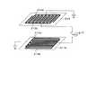
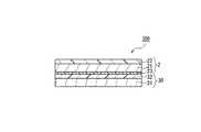
図1は、本発明の一実施形態にかかる液晶ディスプレイ100の概略構成を示す断面図である。図1に示すように、液晶ディスプレイ100は、画像を表示する表示用液晶パネル1(表示装置)と視野角制御用液晶パネル2(視野角制御装置)との2枚の液晶パネルを備えている。本実施形態における表示用液晶パネル1は透過型であり、光源としてバックライト3が用いられる。視野角制御用液晶パネル2は、バックライト3と表示用液晶パネル1との間に設けられている。液晶ディスプレイ100は、視野角制御用液晶パネル2における液晶をスイッチング動作させることにより、表示用液晶パネル1の画像が視認できる視野角が広い状態(広視野角)と、視野角が狭い状態(狭視野角)との間で、表示状態を切替えることができる。狭視野角は、他人に表示用液晶パネル1の画像を見られたくない場合に特に好適に用いられ、広視野角は、それ以外の通常の使用時や、表示用液晶パネル1の画像を複数人で同時に見たい場合等に好適に用いられる。 FIG. 1 is a cross-sectional view showing a schematic configuration of a
表示用液晶パネル1は、一対の透光性基板間に液晶を挟持した液晶セル11と、液晶セル11の表裏に設けられた偏光板12,13とを有する。液晶セル11の液晶モードやセル構造は任意である。また、表示用液晶パネル1の駆動モードも任意である。すなわち、表示用液晶パネル1としては、文字や画像あるいは動画を表示できる任意の液晶パネルを用いることができる。従って、図1においては表示用液晶パネル1の詳細な構造を図示せず、その説明も省略する。また、表示用液晶パネル1は、カラー表示可能なパネルであっても良いし、モノクロ表示専用のパネルであっても良い。さらに、バックライト3の構成にも何ら限定がなく、公知の任意のバックライトを用いることができるので、バックライト3の詳細な構造の図示および説明も省略する。 The display
視野角制御用液晶パネル2は、一対の透光性基板間に液晶層を挟持した液晶セル21と、液晶セル21に対してバックライト3側に設けられた偏光板22と、液晶セル21と偏光板22との間に配置された1/2波長位相差板23とを備えている。 The viewing angle control
ここで、視野角制御用液晶パネル2の液晶セル21の構造について、図2および図3を参照しながら説明する。図2は、液晶セル21の概略構造を示す断面模式図である。図3は、液晶セル21が備える透光性電極の構造を示す模式図である。 Here, the structure of the
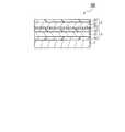
図2に示すように、液晶セル21は、透光性基板211a,211bを備えている。透光性基板211aの表面には、配向膜215aが形成されている。一方、透光性基板211bの表面には、例えばITO(Indium Tin Oxide)を材料として、図3に示すように、互いに対向する櫛歯状の透光性電極212a,212bが形成されている。なお、図2は、1本の透光性電極212a上を、その延伸方向に沿って切断した断面を示しているので、図2には透光性電極212bが表れていない。透光性電極212の上層には、絶縁膜213を介して、透光性電極212a,212bに直交する方向に延伸する透光性電極214a,214bが形成されている。透光性電極214a,214bも、例えばITO(Indium Tin Oxide)を材料として用い、互いに対向する櫛歯状に形成されている。 As shown in FIG. 2, the
図3に示すように、透光性電極212aおよび透光性電極214aは所定電圧を供給する配線に接続されており、透光性電極212b,214bは駆動回路217にスイッチを介して接続されている。すなわち、駆動回路217は、透光性電極212bと透光性電極214bとのいずれか一方に選択的に電圧を印加するようになっている。これにより、透光性電極212bへ駆動回路217から電圧が印加された場合は、櫛歯状に形成されている透光性電極212aと透光性電極212bとの間に、これらの電極の延伸方向にほぼ垂直な電界が生じる。また、透光性電極214bへ駆動回路217から電圧が印加された場合は、櫛歯状に形成されている透光性電極214aと透光性電極214bとの間に、これらの電極の延伸方向にほぼ垂直な電界が生じる。 As shown in FIG. 3, the
透光性電極214a,214bの上層は、配向膜215bで覆われている。そして、透光性基板211a,211bは所定の間隔を保ってシール材(図示せず)を介して貼り合わされ、配向膜215a,215bと前記シール材によって形成された空隙に液晶材料が注入されることにより、液晶層216が形成されている。液晶層216の液晶材料としては、本実施形態においてはポジ型のネマティック液晶を用いるが、ネガ型のネマティック液晶であっても良い。 The upper layers of the
図4は、偏光板22の偏光吸収軸X22、1/2波長位相差板23の光軸(遅相軸)X23、液晶セル21の配向膜215a,215bにおける配向軸Ra,Rb、および、偏光板13の偏光吸収軸X13の関係を示す模式図である。図4に示すように、偏光板22の偏光吸収軸X22と、偏光板13の偏光吸収軸X13とは、互いに平行に設定されている。なお、偏光吸収軸X22と偏光吸収軸X13とは、完全に平行でなくても良く、それらのなす角が−10°〜10°の範囲内であれば、視野角切替えの十分な効果が得られる。1/2波長位相差板23の光軸X23は、偏光板22の偏光吸収軸X22に対して、ほぼ45°をなすように配置されている。液晶セル21の配向膜215a,215bにおける配向軸Ra,Rbは、偏光板22の偏光吸収軸X22にほぼ平行に設定されている。なお、図4の例では、配向軸Ra,Rbは、互いに平行かつ逆方向になるよう設定されているが、平行かつ同方向になるよう設定されていても良い。4, the optical axis of the polarizing
図5は、液晶セル21の配向膜215a,215bにおける配向軸Ra,Rbの向きと、液晶層216の液晶分子の配向状態(電圧無印加時)とを示す断面模式図である。図5(a)に示すように、配向軸Ra,Rbが互いに平行かつ逆方向になるように、配向膜215a,215bに配向処理がなされている場合は、液晶層216の液晶分子216mは、ホモジニアス配向をなす。一方、図5(b)に示すように、配向軸Ra,Rbが互いに平行かつ同方向になるように、配向膜215a,215bに配向処理がなされている場合は、液晶層216の液晶分子216mは、スプレイ配向をなす。なお、図5(a)および(b)においては、説明を分かりやすくするために、プレチルト角の大きさが実際よりも誇張して示されている。本実施形態にかかる視野角制御用液晶パネル2では、図5(a)および(b)にそれぞれ示すホモジニアス配向およびスプレイ配向のいずれであっても、ほぼ同様の効果が得られる。FIG. 5 is a schematic cross-sectional view showing the orientation of alignment axes Ra and Rb in the
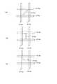
ここで、図6(a)〜(c)を参照し、印加電圧に応じた液晶分子216mのふるまいについて説明する。図6(a)は、液晶セル21に対して電圧が印加されていないとき、図6(b)は、液晶セル21の透光性電極212a,212b間に駆動回路217より所定の電圧が印加されたとき、図6(c)は、液晶セル21の透光性電極214a,214b間に所定の電圧が印加されたときの、液晶分子216mの状態をそれぞれ示す模式図である。なお、本実施形態では、前述したように、液晶層216はポジ型のネマティック液晶、すなわち、液晶分子の長軸方向の誘電率が短軸方向の誘電率よりも大きい液晶であるものとする。 Here, the behavior of the
液晶セル21に対して電圧が印加されていないとき、図6(a)に示すように、液晶セル21の液晶分子216mは、その分子長軸が、配向軸Ra,Rbに平行になるよう配向している。一方、駆動回路217が、透光性電極212a,212b間に所定の電圧を印加したときは、図6(b)に示すように、液晶分子216mは、透光性電極212a,212b間に形成される電界の方向に分子長軸の向きを揃えるように配向する。言い換えると、透光性電極212a,212b間に電圧が印加されると、透光性電極212a,212bの延伸方向にほぼ垂直に等電位面が生じる。液晶分子216mは、この等電位面にダイレクタを一致させるように配向する。また、駆動回路217が、透光性電極214a,214b間に所定の電圧を印加したときは、図6(c)に示すように、液晶分子216mは、透光性電極214a,214b間に形成される電界の方向に分子長軸の向きを揃えるように配向する。When no voltage is applied to the
以上のように、駆動回路217が液晶セル21の透光性電極212a,212b、および透光性電極214a,214bのいずれかへ電圧を選択的に印加することにより、図6(b)および(c)に示すように、液晶分子216mのダイレクタの向きを、基板に平行な面内でスイッチさせることができる。言い換えると、液晶セル21は、図6(b)に示すように、透光性電極212a,212b間に所定の電圧を印加したときには、正面方向に透過する光に対して+λ/4の位相差を生じ、図6(c)に示すように、透光性電極214a,214b間に所定の電圧を印加したときには、正面方向に透過する光に対して−λ/4の位相差を生じる。 As described above, when the
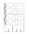
ここで、上述したように、駆動回路217が液晶セル21の透光性電極212a,212b、または透光性電極214a,214bへ電圧を選択的に印加した場合のそれぞれに、視野角制御用液晶パネル2を透過する光に生じる位相差について、図7を参照しながら説明する。図7は、透光性電極212a,212bまたは透光性電極214a,214bに所定の電圧を印加したときに、視野角制御用液晶パネル2を正面方向または斜め方向に透過する光について、各光学部材で生じる位相差を説明する図である。なお、ここでの「斜め方向」とは、方位角が1/2波長位相差板23の光軸にほぼ直交する方向であって、極角が所定の角度(例えば45°)よりも大きい視角方向をいう。なお、極角とは、液晶セル21の基板法線に対して、観察者の視点と液晶セル21の表面中央とを結ぶ線とがなす角度である。 Here, as described above, when the
図7の一番左の欄に示すように、透光性電極212a,212bに電圧を印加した場合は、視野角制御用液晶パネル2を正面方向に透過する光は、まず、偏光板22において偏光吸収軸X22に略直交する直線偏光成分のみが透過する。そして、偏光板22を透過した直線偏光成分は、1/2波長位相差板23に入射して+λ/2の位相遅れを生じ、次に液晶セル21へ入射して上述したようにさらに+λ/4の位相遅れを生じ、合計で4λ/3の位相遅れを持つ円偏光となる。この円偏光が偏光板13へ入射することにより、偏光板13の偏光吸収軸X13に略直交する直線偏光成分のみが透過して観察者に視認されることとなる。As shown in the leftmost column of FIG. 7, when a voltage is applied to the
一方、透光性電極214a,214bに電圧を印加した場合は、図7の左から二番目の欄に示すように、視野角制御用液晶パネル2を正面方向に透過する光は、上記と同様に、まず、偏光板22において偏光吸収軸X22に略直交する直線偏光成分のみが透過する。そして、偏光板22を透過した直線偏光成分は、1/2波長位相差板23に入射して+λ/2の位相遅れを生じ、次に液晶セル21へ入射して、この場合は上述したように−λ/4の位相遅れを生じ、合計でλ/4の位相遅れを持つ円偏光となる。この円偏光が偏光板13へ入射することにより、偏光板13の偏光吸収軸X13に略直交する直線偏光成分のみが透過して観察者に視認されることとなる。On the other hand, when a voltage is applied to the
また、透光性電極212a,212bに電圧を印加した場合は、図7の左から三番目の欄に示すように、視野角制御用液晶パネル2を斜め方向に透過する光は、まず、偏光板22において偏光吸収軸X22に略直交する直線偏光成分のみが透過する。そして、偏光板22を透過した直線偏光成分は、1/2波長位相差板23に入射するが、入射方向が斜めであるので、正面方向から入射した場合の+λ/2よりも大きい位相遅れ(+λ/2+α)を生じ、楕円偏光となる。さらに、液晶セル21においても、正面方向から入射した場合の+λ/4よりも大きい位相遅れ(+λ/4+β)を生じ、合計で(4λ/3+α+β)の位相遅れを持つ楕円偏光となる。この位相差(4λ/3+α+β)は、ほぼλに近い値となる。この楕円偏光が偏光板13へ入射することにより、偏光板13の偏光吸収軸X13に略直交する直線偏光成分のみが透過して観察者に視認されることとなる。Further, when a voltage is applied to the
一方で、透光性電極214a,214bに電圧を印加した場合は、図7の最も右の欄に示すように、視野角制御用液晶パネル2を斜め方向に透過する光は、まず、偏光板22において偏光吸収軸X22に略直交する直線偏光成分のみが透過する。そして、偏光板22を透過した直線偏光成分は、1/2波長位相差板23に入射するが、入射方向が斜めであるので、正面方向から入射した場合の+λ/2よりも大きい位相遅れ(+λ/2+α)を生じ、楕円偏光となる。さらに、液晶セル21においては、正面方向から入射した場合の−λ/4よりも大きい位相遅れ(−λ/4+β)を生じ、合計で(λ/4+α+β)の位相遅れを持つ楕円偏光となる。この位相差(λ/4+α+β)は、ほぼλ/2に近い値となる。この円偏光は、偏光板13へ入射することにより、偏光板13の偏光吸収軸X13に略直交する直線偏光成分のみが透過して観察者に視認されることとなる。On the other hand, when a voltage is applied to the
ここで、最終的に偏光板13を透過して観察者に視認される光の量は、図7から分かるように、正面方向から観察した場合は、透光性電極212a,212bおよび透光性電極214a,214bのいずれに電圧を印加する場合であっても同様であり、正面方向については十分な輝度が得られる。一方、斜め方向から観察した場合は、透光性電極212a,212bに電圧を印加した場合は十分な輝度が得られるが、透光性電極214a,214bに電圧を印加した場合は、透過光量が大きく制限され、表示用液晶パネル1からの出射光をほとんど視認することができない状態となる。従って、透光性電極212a,212bに電圧を印加することにより、正面方向と斜め方向との両方について十分な輝度が得られる広視野角状態を実現できる。一方、透光性電極214a,214bに電圧を印加することにより、正面方向については十分な輝度が得られるが、斜め方向については視野が遮蔽される、いわゆる狭視野角状態を実現できる。 Here, as can be seen from FIG. 7, the amount of light that finally passes through the
なお、1/2波長位相差板23の光軸方向の方位角については、極角が大きい視角についても、液晶層216における複屈折の影響を受けないので、透光性電極212a,212b,214a,214bへの電圧印加状況にかかわらず、視野は遮蔽されない。 Note that the azimuth angle in the optical axis direction of the ½ wavelength
なお、図7は、図4に示したように、偏光板22と偏光板13とをパラレルニコル配置とした場合の状態を示すが、偏光板22と偏光板13とをクロスニコル配置とした場合は、図8に示すように、図7とは逆に、透光性電極212a,212bに電圧を印加することによって狭視野角状態が得られ、透光性電極214a,214bに電圧を印加することによって広視野角状態が得られる。 7 shows a state in which the
以上のように、本実施形態にかかる視野角制御用液晶パネル2を備えた液晶ディスプレイ100は、透光性電極212a,212bまたは透光性電極214a,214bに選択的に電圧を印加することにより、広視野角状態と狭視野角状態とを切り替えることができる。 As described above, the
上記の説明においては、1/2波長位相差板23を備えた構成(図4参照)を例示したが、1/2波長位相差板23は必須ではなく、図9に示すように、図4に示した構成から1/2波長位相差板23を省略した構成も、本発明の一実施形態である。図9に示した構成の場合、液晶セル21の正面方向(法線方向)のリタデーションをλ/4とすればよい。この構成では、液晶セル21の透光性電極212a,212bおよび透光性電極214a,214bのいずれにも電圧を印加しない状態で広視野角状態が得られる。一方、透光性電極212a,212bおよび透光性電極214a,214bの一方に電圧を印加することで狭視野角状態が得られる。このとき、透光性電極212a,212bに電圧を印加した場合と、透光性電極214a,214bに電圧を印加した場合とにおいて、視野が制御される方向(方位角の範囲)が互いに異なる。 In the above description, the configuration including the half-wave retardation plate 23 (see FIG. 4) is illustrated, but the half-
また、図10に示すように、図4に示した構成における1/2波長位相差板23の代わりに、1/4波長位相差板25を備えた構成も、本発明の一実施形態である。この場合、1/4波長位相差板25の光軸X25は、偏光板22の偏光吸収軸X22に対して、ほぼ45°をなすように配置される。また、液晶セル21の正面方向のリタデーションをλ/2とする。図10の構成によれば、透光性電極212a,212bに電圧を印加することにより、正面方向と斜め方向との両方について十分な輝度が得られる広視野角状態を実現できる。一方、透光性電極214a,214bに電圧を印加することにより、正面方向については十分な輝度が得られるが、斜め方向については視野が遮蔽される、いわゆる狭視野角状態を実現できる。Further, as shown in FIG. 10, a configuration including a quarter-
さらに、図11に示すように、図4に示した構成に対して、光学補償フィルム26をさらに備えた構成も、本発明の一実施形態であり、広視野角状態と狭視野角状態との切り替えに関して、図4に示した構成と同じ動作をなす。なお、光学補償フィルム26としては、3次元屈折率がnx=ny>nzの関係を満たすいわゆるネガティブCプレートや、3次元屈折率がnx>ny>nzの関係を満たすいわゆるXプレート等を用いることができる。このような光学補償フィルム26を備えることにより、斜め方向から見た場合の楕円偏光を補償して、出射光を完全な直線偏光とすることができ、当該斜め方向から見たときの遮蔽性を改善することができる。なお、光学補償フィルム26として上記のいわゆるXプレートを用いる場合は、正面方向に対して複屈折の影響がないようにするために、そのnx軸が偏光板22,13の偏光透過軸に対してほぼ平行またはほぼ垂直になるよう配置すれば良い。光学補償フィルム26として上記のいわゆるネガティブCプレートを用いる場合は、ネガティブCプレートは正面方向に対して複屈折を持たないので、光軸の方向は任意で良い。また、図11に示した構成では、光学補償フィルム26が偏光板22と1/2波長位相差板23との間に配置されているが、光学補償フィルム26の位置はこれに限定されない。すなわち、光学補償フィルム26は、1/2波長位相差板23と液晶セル21との間に配置されていても良いし、液晶セル21と位相差板13との間に配置されていても良い。 Further, as shown in FIG. 11, a configuration further including an
なお、図9〜図11においては、偏光板22と偏光板13とがパラレルニコルに配置された例を示したが、偏光板22と偏光板13とはクロスニコル配置であっても良い。 9 to 11 show an example in which the
また、上記の説明では、透光性電極212a,212bが平行な電極を有する櫛形状に形成されている例を示したが、透光性電極212a,212bの各電極がジグザグ形状に形成されていても良い。透光性電極214a,214bについても同様である。また、図4においては、1/2波長位相差板23の光軸X23に対して配向軸Ra,Rbがほぼ45°をなすように設定された構成を例示した。しかし、1/2波長位相差板23の光軸に対して、配向軸Ra,Rbは、必ずしも45°をなしていなくても良い。In the above description, the
また、上記の説明においては、透光性基板211b側に、透光性電極212a,212bと透光性電極214a,214bとの両方を備え、透光性基板211a側には電極を有しない構成を例示した。しかし、透光性電極212a,212bを透光性基板211a側に形成した構成としても良いし、透光性基板211a側に透光性電極212a,212bと透光性電極214a,214bとの両方を備え、透光性基板211b側には電極を有しない構成としても良い。 Further, in the above description, the
さらに、本実施形態にかかる液晶ディスプレイ100は、バックライト3として、一般的なバックライト(極角全範囲にわたってほぼ平均的な輝度分布を有するバックライト)を用いても良いが、指向性バックライトを用いることが好ましい。指向性バックライトとは、ディスプレイの正面方向、すなわち極角φ=0°を中心とした比較的狭い角度範囲の輝度が、他の部分の輝度よりも高くなるような輝度分布を有するバックライトであり、一般的なバックライトに1枚または複数枚のレンズシートを積層することによって実現できる。 Furthermore, the
ここで、図12〜図17を参照し、本実施形態にかかる液晶ディスプレイ100に対して適用可能なバックライトの特性について説明する。図12は、指向性バックライトではない一般的なバックライト(レンズシートなし)を用いた場合のバックライト3の輝度分布図である。この場合、バックライト3は、水平方向(方位角θ=0°からθ=180°の方向)に対称的な輝度分布を有するが、垂直方向(方位角θ=90°からθ=270°の方向)については、輝度のピークP1を方位角θ=270°、極角φ=45°の付近に有する。なお、バックライト3の輝度ピークP1をこのように正面方向からずらした設計としたのは、後述するようにレンズシートを2枚積層した場合に、輝度ピークが真正面(極角φ=0°)に位置するようにしたためである。つまり、レンズシートを用いない場合、あるいはレンズシートを1枚だけ積層する場合は、バックライト3の輝度ピークは、図12に示した位置とは異なる。Here, the characteristics of the backlight applicable to the
図13〜図15は、レンズシートを用いた指向性バックライトとした場合の、バックライト3の輝度分布を示す。図13は、図12の輝度特性を持つバックライトの光出射面にレンズシートを1枚積層した構成とした場合の、バックライト3の輝度分布図である。レンズシートとしては、住友スリーエム株式会社製の「BEF II 90/50(商品名)」を用いたが、これに限定されない。この場合、図13に示すように、レンズシートを光出射面に1枚積層したことによって輝度分布が変化し、輝度のピークP2が方位角θ=270°、極角φ=30°付近に現われる。また、水平方向については極角がおよそ0°≦φ≦40°の範囲、垂直方向については極角がおよそ0°≦φ≦60°の範囲において、他の部分よりも相対的に輝度が高くなる。13 to 15 show the luminance distribution of the
図14は、図12の輝度特性を持つバックライトの光出射面に、上記と同じレンズシートを、図13とは配置角度が90°異なる向きに積層した構成とした場合の、バックライト3の輝度分布図である。この場合、図14に示すように、輝度のピークP3が方位角θ=270°、極角φ=15°付近に現われると共に、水平方向については極角がおよそ0°≦φ≦60°の範囲、垂直方向については極角がおよそ0°≦φ≦40°の範囲において、他の部分よりも相対的に輝度が高くなる。FIG. 14 shows the
図15は、図12の輝度特性を持つバックライトの光出射面に、上記と同じレンズシートを2枚、配置角度が90°異なる向きで積層した構成とした場合の、バックライト3の輝度分布図である。この場合、図15に示すように、輝度のピークP4がほぼ正面(方位角θ=270°、極角φ=5°付近)に現われると共に、水平方向については極角がおよそ0°≦φ≦40°の範囲、垂直方向については極角がおよそ0°≦φ≦40°の範囲において、他の部分よりも相対的に輝度が高くなる。FIG. 15 shows the luminance distribution of the
図16は、バックライト3の水平方向(方位角θ=0°からθ=180°の方向)における輝度分布を、レンズシートの有無の別に示した輝度−極角特性図である。図17は、バックライト3の垂直方向(方位角θ=90°からθ=270°の方向)における輝度分布を、レンズシートの有無の別に示した輝度−極角特性図である。なお、図16では、正面方向(極角φ=0°)から方位角θ=180°側の極角に負の符号を付して表し、図17では、正面方向(極角φ=0°)から方位角θ=270°側の極角に負の符号を付して表した。 FIG. 16 is a luminance-polar angle characteristic diagram showing the luminance distribution of the
図16および図17に示すように、レンズシートを1枚積層した場合、法線方向(極角φ=0°)の輝度は、レンズシートがない場合の約1.8倍(輝度上昇率は約1.60)となる。また、レンズシートを2枚積層した場合は、法線方向の輝度は、レンズシートがない場合の約2.8倍(輝度上昇率は約1.95)となる。ただし、輝度上昇率は、バックライトシステム全体の構成材料や設計または総合的な照明効果に応じて異なるので、上記の輝度上昇率が必ずしも最適であるとは限らない。 As shown in FIGS. 16 and 17, when one lens sheet is laminated, the luminance in the normal direction (polar angle φ = 0 °) is about 1.8 times that without the lens sheet (the rate of increase in luminance is About 1.60). In addition, when two lens sheets are stacked, the luminance in the normal direction is about 2.8 times that when there is no lens sheet (the luminance increase rate is about 1.95). However, since the luminance increase rate varies depending on the constituent material and design of the entire backlight system or the overall lighting effect, the above-described luminance increase rate is not always optimal.
また、図16および図17に示すThは、レンズシートを1枚積層した場合の法線方向の輝度の50%に相当する輝度を表す。このTh以上の輝度が得られる極角の範囲(水平方向)は、図13に示すレンズシートの配置の場合は約66°、図14に示すレンズシートの配置の場合は約96°である。同様に、このTh以上の輝度が得られる極角の範囲(垂直方向)は、図13に示すレンズシートの配置の場合は約99°、図14に示すレンズシートの配置の場合は約66°である。なお、レンズシートを2枚積層した場合、法線方向の輝度の50%に相当する輝度が得られる極角の範囲は、水平方向では約58°であり、垂直方向では約88°である。 Further, Th shown in FIGS. 16 and 17 represents a luminance corresponding to 50% of the luminance in the normal direction when one lens sheet is laminated. The polar angle range (horizontal direction) in which the luminance equal to or higher than Th is obtained is about 66 ° in the case of the lens sheet arrangement shown in FIG. 13 and about 96 ° in the case of the lens sheet arrangement shown in FIG. Similarly, the polar angle range (vertical direction) in which the luminance equal to or higher than Th is obtained is about 99 ° in the case of the lens sheet arrangement shown in FIG. 13 and about 66 ° in the case of the lens sheet arrangement shown in FIG. It is. When two lens sheets are laminated, the polar angle range in which the luminance corresponding to 50% of the luminance in the normal direction is obtained is about 58 ° in the horizontal direction and about 88 ° in the vertical direction.
極角全範囲にわたってほぼ平均的な輝度分布を有する一般的なバックライトの代わりに、上述したような特性を有する指向性バックライトをバックライト3として用いることにより、挟視野角状態において、輝度ピークが正面方向へ近づくと共に、遮光状態となる方位角の範囲がより広くなる。従って、斜め後方にいる他人からの覗き見を、より確実に防止する表示装置を実現できる。 By using a directional backlight having the above-described characteristics as the
図18は、本実施形態にかかる液晶ディスプレイ100の変形例としての液晶ディスプレイ200の構成を示す。図1と図18とを比較することから分かるように、液晶ディスプレイ100と液晶ディスプレイ200とは、表示用液晶パネル1と視野角制御用液晶パネル2との積層順序が逆になっている。すなわち、図18に示すように、液晶ディスプレイ200は、バックライト3の上に表示用液晶パネル1が積層され、さらにその上に視野角制御用液晶パネル2が積層された構成である。なお、液晶ディスプレイ200において、表示用液晶パネル1は、半透過型液晶パネルであっても良い。 FIG. 18 shows a configuration of a
以上のように、本実施形態にかかる液晶ディスプレイ100,200によれば、視野角制御用液晶パネル2の液晶セル21において、透光性電極212a,212b間および透光性電極214a,214b間のいずれかに選択的に電圧を印加することにより、広い視野から表示を視認できる広視野角の表示と、限られた視野角からのみ表示を視認できる狭視野角の表示を実現できる。 As described above, according to the
なお、本実施形態は、あくまでも本発明の具体例を示すものであって、本発明の技術的範囲をこれらの具体例に限定する意図はない。例えば、上記の説明では、視野角制御用液晶パネル2の液晶層216全体が一様に制御される構成を例示した。しかし、液晶セル21の電極構造や配向処理の向きを局所領域毎に異ならせれば、液晶の動作を局所領域毎に制御することができる。これにより、表示画面の視野角の広さを局所領域毎に異ならせることも可能である。 In addition, this embodiment shows the specific example of this invention to the last, Comprising: There is no intention which limits the technical scope of this invention to these specific examples. For example, in the above description, the configuration in which the entire
また、上記の説明では、表示装置の背面または前面に視野角制御装置を配置した例を説明したが、表示装置の背面と前面との両方に視野角制御装置を配置した構成も、本発明の技術的範囲に含まれる。 In the above description, the example in which the viewing angle control device is disposed on the back surface or the front surface of the display device has been described. However, the configuration in which the viewing angle control device is disposed on both the back surface and the front surface of the display device is also applicable. Included in the technical scope.
また、上記の説明では、表示装置の具体例として、透過型液晶パネルを挙げたが、表示装置はこれに限定されない。例えば、反射型または半透過型の液晶表示パネルを表示装置として用いることもできる。また、液晶表示パネルのような非発光型表示装置に限らず、例えば、CRT(Cathode Ray Tube)、プラズマディスプレイ、有機EL(Electronic Luminescence)素子、無機EL素子、LED(Light Emitting Diode)ディスプレイ、蛍光表示管(Vacuum Fluorescent Display)、電界放出ディスプレイ(Field Emission Display)、表面電界ディスプレイ(Surface-conduction Electron-emitter Display)等の自発光型表示装置を用いることもできる。 In the above description, the transmissive liquid crystal panel is given as a specific example of the display device, but the display device is not limited to this. For example, a reflective or transflective liquid crystal display panel can be used as the display device. In addition to a non-light emitting display device such as a liquid crystal display panel, for example, a CRT (Cathode Ray Tube), a plasma display, an organic EL (Electronic Luminescence) element, an inorganic EL element, an LED (Light Emitting Diode) display, fluorescence A self-luminous display device such as a display tube (Vacuum Fluorescent Display), a field emission display (Field Emission Display), or a surface electric field display (Surface-conduction Electron-emitter Display) can also be used.
図19は、表示装置として、反射型の液晶表示パネルを用いた場合の構成例である。図19に示す液晶ディスプレイ300は、反射型液晶表示パネル30の前面(観察者側)に、視野角制御用液晶パネル2を配置した構成である。反射型液晶表示パネル30は、観察者と反対側の基板に反射板(図示せず)を備えた反射型液晶セル31と、反射型液晶セル31の上面に配置された偏光板32とを備えている。反射型液晶セルの構造および動作は周知であるため、ここでは詳細な説明を省略する。図19に示す液晶ディスプレイ300においても、液晶ディスプレイ100と同様に、視野角制御用液晶パネル2の液晶セル21において、透光性電極212a,212b間および透光性電極214a,214b間のいずれかに選択的に電圧を印加することにより、液晶ディスプレイ300の表示状態を広視野角と狭視野角との間で切替えることができる。 FIG. 19 shows a configuration example in the case where a reflective liquid crystal display panel is used as the display device. The
また、図20は、表示装置として、例えばEL素子等の自発光型表示装置を用いた場合の構成例である。図20に示すディスプレイ400は、自発光型表示装置40の前面(観察者側)に、視野角制御用液晶パネル2を配置した構成である。この場合は、視野角制御用液晶パネル2は、液晶セル21の表裏に、一対の偏光板22,24を備えている。偏光板22,24の偏光吸収軸は、互いに略直交するよう配置されている。図20に示すディスプレイ400においても、液晶ディスプレイ100と同様に、視野角制御用液晶パネル2の液晶セル21において、透光性電極212a,212b間および透光性電極214a,214b間のいずれかに選択的に電圧を印加することにより、ディスプレイ400の表示状態を広視野角と狭視野角との間で切替えることができる。 FIG. 20 shows a configuration example when a self-luminous display device such as an EL element is used as the display device. The
なお、上記の実施形態のいずれにおいても、ディスプレイの表示状態が狭視野角であるときに、ユーザにその旨を知らせるためのメッセージ、画像、またはアイコン等を、表示装置の画面に表示するようにしても良い。 In any of the above embodiments, when the display state of the display is a narrow viewing angle, a message, an image, an icon, or the like for informing the user is displayed on the screen of the display device. May be.
また、上記の実施形態のいずれにおいても、表示装置で表示される画像の内容に応じて視野角制御装置の駆動回路が動作し、狭視野角と広視野角とを自動的に切替えるようにしても良い。例えば、ディスプレイがインターネットのウェブページを見るために用いられる場合、ウェブページの内容に応じて各ページに関連付けられたソフトウェアフラッグを参照し、他人から見られないことが好ましい内容である場合等に、狭視野角の表示状態に自動的に切替えるようにしても良い。また、ブラウザが暗号化モードで起動された場合に、狭視野角の表示状態へ切替えるようにしても良い。 In any of the above embodiments, the driving circuit of the viewing angle control device operates according to the content of the image displayed on the display device, and automatically switches between the narrow viewing angle and the wide viewing angle. Also good. For example, when the display is used to view a web page on the Internet, referring to the software flag associated with each page according to the content of the web page, and when it is preferable content not to be seen by others, etc. You may make it switch automatically to the display state of a narrow viewing angle. Further, when the browser is activated in the encryption mode, the display state may be switched to a narrow viewing angle.
また、ディスプレイが、データ入力装置の一部である場合、またはデータ入力装置と関連し、入力されているデータタイプまたは入力されようとするデータタイプが機密性を有するものである場合等に、ディスプレイの表示状態を狭視野角に切替えるよう調整することも可能である。例えば、ユーザが何らかの個人識別番号を入力したとき等に、ディスプレイが自動的に狭視野角に切り替わるようにすれば良い。 In addition, when the display is a part of the data input device, or when the data type to be input or the data type to be input is confidential, the display is related to the data input device. It is also possible to adjust the display state to be switched to a narrow viewing angle. For example, the display may be automatically switched to a narrow viewing angle when the user inputs some personal identification number.
なお、上記の実施形態のいずれにおいても、視野角制御装置は、表示装置から取り外しが可能なモジュールまたはカバーとして形成されても良い。そのような取り外し可能なモジュールは、表示装置に取り付けられたときに、表示装置に電気的に接続されることによって、適切な電力と制御信号を得ることができる。 In any of the above embodiments, the viewing angle control device may be formed as a module or a cover that can be detached from the display device. When such a removable module is attached to the display device, it can be electrically connected to the display device to obtain appropriate power and control signals.
また、上記の実施形態のいずれにおいても、ディスプレイの周囲光を測定する光学センサ(アンビエントセンサ)をさらに備え、光学センサの測定値が所定の閾値を下回るときに、ディスプレイの表示状態を狭視野角とすることも好ましい。 In any of the above-described embodiments, an optical sensor (ambient sensor) that measures the ambient light of the display is further provided, and when the measured value of the optical sensor falls below a predetermined threshold, the display state of the display is set to a narrow viewing angle. It is also preferable that
なお、本発明にかかるディスプレイおよび視野角制御装置の用途は多岐に亘る。例えば、ノート型パーソナルコンピュータ、携帯型情報端末(PDA)、携帯型ゲーム機、または携帯電話等のディスプレイに適用されるだけでなく、ATM(現金自動受け払い機)、公共の場に設置される情報端末、券売機、および車載用ディスプレイ等、様々な機器のディスプレイに適用される。 The display and the viewing angle control device according to the present invention have a wide variety of uses. For example, it is not only applied to a display of a notebook personal computer, a portable information terminal (PDA), a portable game machine, or a cellular phone, but also installed in an ATM (automatic cash dispenser) or a public place. It is applied to displays of various devices such as information terminals, ticket vending machines, and in-vehicle displays.
また、本発明にかかる視野角制御装置は、ディスプレイに組み込まれた状態で実施されることもあるが、ディスプレイの部品として、視野角制御装置単体で製造され、流通する可能性もある。 In addition, the viewing angle control device according to the present invention may be implemented in a state of being incorporated in a display, but as a display component, the viewing angle control device may be manufactured and distributed as a single unit.
本発明は、広視野角と狭視野角とを切替えることにより様々な使用環境や用途に適応可能なディスプレイと、これに用いられる視野角制御装置として、産業上利用可能である。 INDUSTRIAL APPLICABILITY The present invention is industrially applicable as a display that can be adapted to various usage environments and applications by switching between a wide viewing angle and a narrow viewing angle, and a viewing angle control device used therefor.
1 表示用液晶パネル
2 視野角制御用液晶パネル
3 バックライト
11 液晶セル
12 偏光板
13 偏光板
21 液晶セル
212a,212b 透光性電極
213 絶縁膜
214a,214b 透光性電極
215a,215b 配向膜
216 液晶層
216m 液晶分子
217 駆動回路
22 偏光板
23 1/2波長位相差板
24 偏光板
25 1/4波長位相差板
26 光学補償フィルム
30 反射型液晶表示パネル
31 液晶セル
32 偏光板
40 自発光型表示装置
100 液晶ディスプレイ
200 液晶ディスプレイ
300 ディスプレイ
400 ディスプレイDESCRIPTION OF
Claims (26)
Translated fromJapanese前記表示装置の背面および前面の少なくとも一方に配置され、前記表示装置の視野角を制御する視野角制御装置とを備えたディスプレイであって、
前記視野角制御装置は、一対の透光性基板間に液晶分子をホモジニアス配向またはスプレイ配向させた液晶層を有する液晶セルと、前記液晶層へ電圧を印加する駆動回路とを備え、
前記液晶セルは、前記一対の透光性基板の一方である第1の透光性基板に、第1の透光性電極群を備えると共に、前記第1の透光性基板または前記一対の透光性基板の他方である第2の透光性基板に、前記第1の透光性電極群における電極の延伸方向に略直交するように設けられた第2の透光性電極群を備え、
前記駆動回路は、前記第1の透光性電極群および第2の透光性電極群に接続され、
前記液晶セルは、当該ディスプレイ内で、2枚の偏光板の間に配置され、
前記駆動回路が、前記第1の透光性電極群および第2の透光性電極群のいずれかに選択的に電圧を印加し、電圧が印加された電極群において隣接する電極間に電界を発生させることにより、表示状態を、第1の視野角範囲を提供する第1の状態と、第1の視野角範囲内にあり第1の視野角範囲よりも狭い第2の視野角範囲を提供する第2の状態との間で切替え可能とすることを特徴とするディスプレイ。A display device driven according to an image to be displayed;
A display provided with at least one of a rear surface and a front surface of the display device, and a viewing angle control device for controlling a viewing angle of the display device,
The viewing angle control device includes a liquid crystal cell having a liquid crystal layer in which liquid crystal molecules are homogeneously or splay aligned between a pair of translucent substrates, and a drive circuit for applying a voltage to the liquid crystal layer,
The liquid crystal cell includes a first translucent electrode group on a first translucent substrate that is one of the pair of translucent substrates, and the first translucent substrate or the pair of translucent substrates. The second light-transmitting substrate that is the other of the light-transmitting substrates includes a second light-transmitting electrode group provided so as to be substantially orthogonal to the extending direction of the electrodes in the first light-transmitting electrode group,
The drive circuit is connected to the first translucent electrode group and the second translucent electrode group,
The liquid crystal cell is disposed between two polarizing plates in the display,
The drive circuit selectively applies a voltage to either the first light transmissive electrode group or the second light transmissive electrode group, and generates an electric field between adjacent electrodes in the electrode group to which the voltage is applied. By generating the display state, the first state providing the first viewing angle range and the second viewing angle range within the first viewing angle range and narrower than the first viewing angle range are provided. A display that is switchable between a second state and a second state.
前記2枚の偏光板が、その偏光吸収軸が−10°〜10°の範囲で交差するよう配置され、
前記液晶セルの正面方向のリタデーションが、前記第1の状態および第2の状態において、λ/4と3λ/4との間で切り替わる、請求項5に記載のディスプレイ。The retardation plate includes a half-wave retardation plate,
The two polarizing plates are arranged such that their polarization absorption axes intersect within a range of −10 ° to 10 °,
The display according to claim 5, wherein the retardation in the front direction of the liquid crystal cell switches between λ / 4 and 3λ / 4 in the first state and the second state.
前記2枚の偏光板が、その偏光吸収軸が80°〜100°の範囲で交差するよう配置され、
前記液晶セルの正面方向のリタデーションが、前記第1の状態および第2の状態において、λ/4と3λ/4との間で切り替わる、請求項5に記載のディスプレイ。The retardation plate includes a half-wave retardation plate,
The two polarizing plates are arranged so that their polarization absorption axes intersect within a range of 80 ° to 100 °,
The display according to claim 5, wherein the retardation in the front direction of the liquid crystal cell switches between λ / 4 and 3λ / 4 in the first state and the second state.
前記2枚の偏光板が、その偏光吸収軸が−10°〜10°の範囲で交差するよう配置され、
前記液晶セルの正面方向のリタデーションがλ/2である、請求項5に記載のディスプレイ。The retardation plate includes a quarter-wave retardation plate,
The two polarizing plates are arranged such that their polarization absorption axes intersect within a range of −10 ° to 10 °,
The display according to claim 5, wherein retardation of the liquid crystal cell in the front direction is λ / 2.
前記2枚の偏光板が、その偏光吸収軸が80°〜100°の範囲で交差するよう配置され、
前記液晶セルの正面方向のリタデーションがλ/2である、請求項5に記載のディスプレイ。The retardation plate includes a quarter-wave retardation plate,
The two polarizing plates are arranged so that their polarization absorption axes intersect within a range of 80 ° to 100 °,
The display according to claim 5, wherein retardation of the liquid crystal cell in the front direction is λ / 2.
前記2枚の偏光板のうち1枚が、前記表示装置に設けられた偏光板である、請求項1〜17のいずれか一項に記載のディスプレイ。The display device is a display device that emits linearly polarized light,
The display according to claim 1, wherein one of the two polarizing plates is a polarizing plate provided in the display device.
前記2枚の偏光板のうち1枚は、前記自発光型表示装置と前記視野角制御装置との間に設けられている、請求項1〜17のいずれか一項に記載のディスプレイ。The display device is a self-luminous display device,
The display according to claim 1, wherein one of the two polarizing plates is provided between the self-luminous display device and the viewing angle control device.
一対の透光性基板間に液晶分子をホモジニアス配向またはスプレイ配向させた液晶層を有する液晶セルと、
前記液晶層へ電圧を印加する駆動回路と、
前記液晶セルに対して前記表示装置の反対側に配置された直線偏光板とを備え、
前記液晶セルは、前記一対の透光性基板の一方である第1の透光性基板に、第1の透光性電極群を備えると共に、前記第1の透光性基板または前記一対の透光性基板の他方である第2の透光性基板に、前記第1の透光性電極群における電極の延伸方向に略直交するように設けられた第2の透光性電極群を備え、
前記駆動回路は、前記第1の透光性電極群および第2の透光性電極群に接続され、前記第1の透光性電極群および第2の透光性電極群のいずれかに選択的に電圧を印加し、電圧が印加された電極群において隣接する電極間に電界を発生させることにより、光の出射範囲を、第1の視野角範囲を提供する第1の状態と、第1の視野角範囲内にあり第1の視野角範囲よりも狭い第2の視野角範囲を提供する第2の状態との間で切替え可能とすることを特徴とする視野角制御装置。A viewing angle control device which is arranged according to an image to be displayed and is arranged on at least one of a back surface and a front surface of a display device which emits linearly polarized light, and is used for controlling a viewing angle of the display device,
A liquid crystal cell having a liquid crystal layer in which liquid crystal molecules are homogeneously or splay aligned between a pair of translucent substrates;
A drive circuit for applying a voltage to the liquid crystal layer;
A linearly polarizing plate disposed on the opposite side of the display device with respect to the liquid crystal cell,
The liquid crystal cell includes a first translucent electrode group on a first translucent substrate that is one of the pair of translucent substrates, and the first translucent substrate or the pair of translucent substrates. The second light-transmitting substrate that is the other of the light-transmitting substrates includes a second light-transmitting electrode group provided so as to be substantially orthogonal to the extending direction of the electrodes in the first light-transmitting electrode group,
The drive circuit is connected to the first light transmissive electrode group and the second light transmissive electrode group, and is selected as one of the first light transmissive electrode group and the second light transmissive electrode group A first state of providing a first viewing angle range by first applying a voltage and generating an electric field between adjacent electrodes in the electrode group to which the voltage is applied; A viewing angle control device capable of switching between a second state that provides a second viewing angle range that is within the viewing angle range and is narrower than the first viewing angle range.
一対の透光性基板間に液晶分子をホモジニアス配向またはスプレイ配向させた液晶層を有する液晶セルと、
前記液晶層へ電圧を印加する駆動回路と、
前記一対の透光性基板の外側に設けられた一対の偏光板とを備え、
前記液晶セルは、前記一対の透光性基板の一方である第1の透光性基板に、第1の透光性電極群を備えると共に、前記第1の透光性基板または前記一対の透光性基板の他方である第2の透光性基板に、前記第1の透光性電極群における電極の延伸方向に略直交するように設けられた第2の透光性電極群を備え、
前記駆動回路は、前記第1の透光性電極群および第2の透光性電極群に接続され、前記第1の透光性電極群および第2の透光性電極群のいずれかに選択的に電圧を印加し、電圧が印加された電極群において隣接する電極間に電界を発生させることにより、光の出射範囲を、第1の視野角範囲を提供する第1の状態と、第1の視野角範囲内にあり第1の視野角範囲よりも狭い第2の視野角範囲を提供する第2の状態との間で切替え可能とすることを特徴とする視野角制御装置。A viewing angle control device that is disposed in front of a self-luminous display device that is driven according to an image to be displayed and is used to control the viewing angle of the self-luminous display device,
A liquid crystal cell having a liquid crystal layer in which liquid crystal molecules are homogeneously or splay aligned between a pair of translucent substrates;
A drive circuit for applying a voltage to the liquid crystal layer;
A pair of polarizing plates provided outside the pair of translucent substrates,
The liquid crystal cell includes a first translucent electrode group on a first translucent substrate that is one of the pair of translucent substrates, and the first translucent substrate or the pair of translucent substrates. The second light-transmitting substrate that is the other of the light-transmitting substrates includes a second light-transmitting electrode group provided so as to be substantially orthogonal to the extending direction of the electrodes in the first light-transmitting electrode group,
The drive circuit is connected to the first light transmissive electrode group and the second light transmissive electrode group, and is selected as one of the first light transmissive electrode group and the second light transmissive electrode group A first state of providing a first viewing angle range by first applying a voltage and generating an electric field between adjacent electrodes in the electrode group to which the voltage is applied; A viewing angle control device capable of switching between a second state that provides a second viewing angle range that is within the viewing angle range and is narrower than the first viewing angle range.
Priority Applications (1)
| Application Number | Priority Date | Filing Date | Title |
|---|---|---|---|
| JP2007182533AJP2009020293A (en) | 2007-07-11 | 2007-07-11 | Display and viewing angle control device used therefor |
Applications Claiming Priority (1)
| Application Number | Priority Date | Filing Date | Title |
|---|---|---|---|
| JP2007182533AJP2009020293A (en) | 2007-07-11 | 2007-07-11 | Display and viewing angle control device used therefor |
Publications (1)
| Publication Number | Publication Date |
|---|---|
| JP2009020293Atrue JP2009020293A (en) | 2009-01-29 |
Family
ID=40359981
Family Applications (1)
| Application Number | Title | Priority Date | Filing Date |
|---|---|---|---|
| JP2007182533AWithdrawnJP2009020293A (en) | 2007-07-11 | 2007-07-11 | Display and viewing angle control device used therefor |
Country Status (1)
| Country | Link |
|---|---|
| JP (1) | JP2009020293A (en) |
Cited By (29)
| Publication number | Priority date | Publication date | Assignee | Title |
|---|---|---|---|---|
| CN105223743A (en)* | 2015-08-25 | 2016-01-06 | 昆山龙腾光电有限公司 | The switchable liquid crystal indicator in visual angle |
| CN105372883A (en)* | 2015-11-03 | 2016-03-02 | 昆山龙腾光电有限公司 | Liquid crystal display device with switchable visual angle |
| WO2019103012A1 (en)* | 2017-11-27 | 2019-05-31 | 富士フイルム株式会社 | Display device |
| US20190293974A1 (en)* | 2018-03-26 | 2019-09-26 | Coretronic Corporation | Anti-peeping control device and backlight module and display using same |
| JPWO2018221413A1 (en)* | 2017-05-29 | 2020-02-27 | 富士フイルム株式会社 | Display device |
| KR20200122326A (en)* | 2018-01-25 | 2020-10-27 | 리얼디 스파크, 엘엘씨 | Reflective optical stack for privacy display |
| CN112088330A (en)* | 2018-04-27 | 2020-12-15 | 日东电工株式会社 | Liquid crystal display device having a plurality of pixel electrodes |
| CN113808478A (en)* | 2020-06-17 | 2021-12-17 | 北京小米移动软件有限公司 | Screen assembly and its control method, control device and electronic device |
| US11624944B2 (en) | 2020-07-29 | 2023-04-11 | Reald Spark, Llc | Backlight for switchable directional display |
| US11668963B2 (en) | 2020-04-30 | 2023-06-06 | Reald Spark, Llc | Directional display apparatus |
| US11733578B2 (en) | 2019-11-13 | 2023-08-22 | ReaID Spark, LLC | Display device with uniform off-axis luminance reduction |
| US11740496B2 (en) | 2020-07-29 | 2023-08-29 | Reald Spark, Llc | Pupillated illumination apparatus |
| US11747693B2 (en) | 2018-07-18 | 2023-09-05 | Reald Spark, Llc | Optical stack for switchable directional display |
| US11796828B2 (en) | 2019-12-10 | 2023-10-24 | Reald Spark, Llc | Control of reflections of a display device |
| US11809052B2 (en) | 2018-06-29 | 2023-11-07 | Reald Spark, Llc | Stabilization for privacy display |
| US11808965B2 (en) | 2018-03-22 | 2023-11-07 | Reald Spark, Llc | Optical waveguide for directional backlight |
| JP2023173806A (en)* | 2022-05-26 | 2023-12-07 | 株式会社ジャパンディスプレイ | Optical element and display device |
| US11874541B2 (en) | 2019-07-02 | 2024-01-16 | Reald Spark, Llc | Directional display apparatus |
| US11892717B2 (en) | 2021-09-30 | 2024-02-06 | Reald Spark, Llc | Marks for privacy display |
| US11892718B2 (en) | 2022-04-07 | 2024-02-06 | Reald Spark, Llc | Directional display apparatus |
| US11977286B2 (en) | 2022-02-09 | 2024-05-07 | Reald Spark, Llc | Observer-tracked privacy display |
| US12038649B2 (en) | 2018-11-07 | 2024-07-16 | Reald Spark, Llc | Directional display apparatus |
| US12066717B2 (en) | 2017-09-15 | 2024-08-20 | Reald Spark, Llc | Optical stack for switchable directional display |
| US12140847B2 (en) | 2018-10-03 | 2024-11-12 | ReaID Spark, LLC | Display apparatus using application software context for privacy control |
| US12169339B2 (en) | 2018-01-25 | 2024-12-17 | Reald Spark, Llc | Touch screen for privacy display |
| US12253748B2 (en) | 2023-04-25 | 2025-03-18 | Reald Spark, Llc | Switchable privacy display |
| US12366701B2 (en) | 2017-05-08 | 2025-07-22 | Reald Spark, Llc | Optical stack for imaging directional backlights |
| US12393066B2 (en) | 2023-08-03 | 2025-08-19 | Reald Spark, Llc | Privacy displays |
| US12392949B2 (en) | 2016-05-19 | 2025-08-19 | Reald Spark, Llc | Wide angle imaging directional backlights |
- 2007
- 2007-07-11JPJP2007182533Apatent/JP2009020293A/ennot_activeWithdrawn
Cited By (50)
| Publication number | Priority date | Publication date | Assignee | Title |
|---|---|---|---|---|
| CN105223743A (en)* | 2015-08-25 | 2016-01-06 | 昆山龙腾光电有限公司 | The switchable liquid crystal indicator in visual angle |
| CN105372883A (en)* | 2015-11-03 | 2016-03-02 | 昆山龙腾光电有限公司 | Liquid crystal display device with switchable visual angle |
| US20170123241A1 (en)* | 2015-11-03 | 2017-05-04 | Infovision Optoelectronics (Kunshan) Co., Ltd. | Liquid crystal display with switchable viewing angle and method of viewing angle control |
| US10371971B2 (en) | 2015-11-03 | 2019-08-06 | Infovision Optoelectronics (Kushan) Co., Ltd. | Liquid crystal display with switchable viewing angle and method of viewing angle control |
| US12392949B2 (en) | 2016-05-19 | 2025-08-19 | Reald Spark, Llc | Wide angle imaging directional backlights |
| US12366701B2 (en) | 2017-05-08 | 2025-07-22 | Reald Spark, Llc | Optical stack for imaging directional backlights |
| JPWO2018221413A1 (en)* | 2017-05-29 | 2020-02-27 | 富士フイルム株式会社 | Display device |
| US10747057B2 (en) | 2017-05-29 | 2020-08-18 | Fujifilm Corporation | Display device |
| US12066717B2 (en) | 2017-09-15 | 2024-08-20 | Reald Spark, Llc | Optical stack for switchable directional display |
| US10871666B2 (en) | 2017-11-27 | 2020-12-22 | Fujifilm Corporation | Display device comprising a viewing angle switching element having a first linear polarizer, an optically anisotropic layer, a viewing angle control cell, and a second linear polarizer |
| WO2019103012A1 (en)* | 2017-11-27 | 2019-05-31 | 富士フイルム株式会社 | Display device |
| JPWO2019103012A1 (en)* | 2017-11-27 | 2020-12-17 | 富士フイルム株式会社 | Display device |
| US12038633B2 (en) | 2018-01-25 | 2024-07-16 | Reald Spark, Llc | Reflective optical stack for privacy display |
| US12169339B2 (en) | 2018-01-25 | 2024-12-17 | Reald Spark, Llc | Touch screen for privacy display |
| JP2021513101A (en)* | 2018-01-25 | 2021-05-20 | リアルディー スパーク エルエルシー | Reflective optical stack for privacy displays |
| KR102853103B1 (en)* | 2018-01-25 | 2025-09-03 | 리얼디 스파크, 엘엘씨 | Reflective optical stack for privacy displays |
| JP7615219B2 (en) | 2018-01-25 | 2025-01-16 | リアルディー スパーク エルエルシー | Reflective Optical Stacks for Privacy Displays |
| US11630336B2 (en) | 2018-01-25 | 2023-04-18 | Reald Spark, Llc | Reflective optical stack for privacy display |
| KR20200122326A (en)* | 2018-01-25 | 2020-10-27 | 리얼디 스파크, 엘엘씨 | Reflective optical stack for privacy display |
| JP7291444B2 (en) | 2018-01-25 | 2023-06-15 | リアルディー スパーク エルエルシー | Display device and viewing angle control optical element |
| JP2023123475A (en)* | 2018-01-25 | 2023-09-05 | リアルディー スパーク エルエルシー | Reflective optical stack for privacy display |
| US11808965B2 (en) | 2018-03-22 | 2023-11-07 | Reald Spark, Llc | Optical waveguide for directional backlight |
| US20190293974A1 (en)* | 2018-03-26 | 2019-09-26 | Coretronic Corporation | Anti-peeping control device and backlight module and display using same |
| CN110361883A (en)* | 2018-03-26 | 2019-10-22 | 中强光电股份有限公司 | Peep-proof control device and the backlight module and display for using it |
| US10921622B2 (en)* | 2018-03-26 | 2021-02-16 | Coretronic Corporation | Anti-peeping control device and backlight module and display using same |
| CN112088330A (en)* | 2018-04-27 | 2020-12-15 | 日东电工株式会社 | Liquid crystal display device having a plurality of pixel electrodes |
| US11809052B2 (en) | 2018-06-29 | 2023-11-07 | Reald Spark, Llc | Stabilization for privacy display |
| US11874576B2 (en) | 2018-06-29 | 2024-01-16 | Reald Spark, Llc | Optical stack for privacy display |
| US11747693B2 (en) | 2018-07-18 | 2023-09-05 | Reald Spark, Llc | Optical stack for switchable directional display |
| US12174504B2 (en) | 2018-07-18 | 2024-12-24 | Reald Spark, Llc | Optical stack for switchable directional display |
| US12140847B2 (en) | 2018-10-03 | 2024-11-12 | ReaID Spark, LLC | Display apparatus using application software context for privacy control |
| US12038649B2 (en) | 2018-11-07 | 2024-07-16 | Reald Spark, Llc | Directional display apparatus |
| US11874541B2 (en) | 2019-07-02 | 2024-01-16 | Reald Spark, Llc | Directional display apparatus |
| US11733578B2 (en) | 2019-11-13 | 2023-08-22 | ReaID Spark, LLC | Display device with uniform off-axis luminance reduction |
| US12228835B2 (en) | 2019-11-13 | 2025-02-18 | ReaID Spark, LLC | Display device with uniform off-axis luminance reduction |
| US12117621B2 (en) | 2019-12-10 | 2024-10-15 | RealD Spark | Control of reflections of a display device |
| US11796828B2 (en) | 2019-12-10 | 2023-10-24 | Reald Spark, Llc | Control of reflections of a display device |
| US11668963B2 (en) | 2020-04-30 | 2023-06-06 | Reald Spark, Llc | Directional display apparatus |
| CN113808478A (en)* | 2020-06-17 | 2021-12-17 | 北京小米移动软件有限公司 | Screen assembly and its control method, control device and electronic device |
| US11740496B2 (en) | 2020-07-29 | 2023-08-29 | Reald Spark, Llc | Pupillated illumination apparatus |
| US11624944B2 (en) | 2020-07-29 | 2023-04-11 | Reald Spark, Llc | Backlight for switchable directional display |
| US12013603B2 (en) | 2020-07-29 | 2024-06-18 | ReaID Spark, LLC | Pupillated illumination apparatus |
| US11892717B2 (en) | 2021-09-30 | 2024-02-06 | Reald Spark, Llc | Marks for privacy display |
| US11921367B2 (en) | 2021-09-30 | 2024-03-05 | Reald Spark, Llc | Marks for privacy display |
| US11977286B2 (en) | 2022-02-09 | 2024-05-07 | Reald Spark, Llc | Observer-tracked privacy display |
| US12259608B2 (en) | 2022-02-09 | 2025-03-25 | Reald Spark, Llc | Observer-tracked privacy display |
| US11892718B2 (en) | 2022-04-07 | 2024-02-06 | Reald Spark, Llc | Directional display apparatus |
| JP2023173806A (en)* | 2022-05-26 | 2023-12-07 | 株式会社ジャパンディスプレイ | Optical element and display device |
| US12253748B2 (en) | 2023-04-25 | 2025-03-18 | Reald Spark, Llc | Switchable privacy display |
| US12393066B2 (en) | 2023-08-03 | 2025-08-19 | Reald Spark, Llc | Privacy displays |
Similar Documents
| Publication | Publication Date | Title |
|---|---|---|
| JP2009020293A (en) | Display and viewing angle control device used therefor | |
| CN101681577B (en) | Display and viewing angle control element for the display | |
| CN100437278C (en) | Display | |
| JP4704349B2 (en) | Display device, viewing angle control device, and electronic device | |
| CN101681572B (en) | Display and viewing angle control element used for same | |
| US8045097B2 (en) | Liquid crystal display device and viewing angle control module | |
| JP4494410B2 (en) | Display device, viewing angle control device, and electronic device | |
| JP3823972B2 (en) | Viewing angle control element, display device, and electronic device | |
| WO2008001896A1 (en) | Display and field-of-view angle control device used for the same | |
| JP2008096458A (en) | Display and viewing angle control device used therefor | |
| JPWO2018221413A1 (en) | Display device | |
| JPWO2007138731A1 (en) | Liquid crystal display | |
| JP2008064790A (en) | Display and viewing angle control device used therefor | |
| JP4347163B2 (en) | Display device and electronic device | |
| JPWO2019103012A1 (en) | Display device | |
| WO2008047754A1 (en) | Display and viewing angle control device used for same | |
| JP2008299280A (en) | Display and viewing angle control device used therefor | |
| US8203671B2 (en) | View angle controllable display device and terminal having the same | |
| WO2007094390A1 (en) | Display and view angle controller used for same | |
| WO2007094358A1 (en) | Display, and viewing angle control device used therein | |
| JP4470904B2 (en) | Viewing angle control element, display device, and electronic device | |
| JP2008051993A (en) | Electro-optical device, viewing angle control element, and electronic apparatus | |
| KR20080013286A (en) | Display panel and display device having same | |
| WO2007094386A1 (en) | Display and view angle control device used for the same | |
| WO2007139193A1 (en) | Display and filed-of-view angle control device used in the same |
Legal Events
| Date | Code | Title | Description |
|---|---|---|---|
| A300 | Withdrawal of application because of no request for examination | Free format text:JAPANESE INTERMEDIATE CODE: A300 Effective date:20101005 |