JP2009016241A - Power plug connector - Google Patents
Power plug connectorDownload PDFInfo
- Publication number
- JP2009016241A JP2009016241AJP2007178245AJP2007178245AJP2009016241AJP 2009016241 AJP2009016241 AJP 2009016241AJP 2007178245 AJP2007178245 AJP 2007178245AJP 2007178245 AJP2007178245 AJP 2007178245AJP 2009016241 AJP2009016241 AJP 2009016241A
- Authority
- JP
- Japan
- Prior art keywords
- power
- logic circuit
- connector
- terminal
- connection
- Prior art date
- Legal status (The legal status is an assumption and is not a legal conclusion. Google has not performed a legal analysis and makes no representation as to the accuracy of the status listed.)
- Pending
Links
Images


Landscapes
- Details Of Connecting Devices For Male And Female Coupling (AREA)
Abstract
Translated fromJapaneseDescription
Translated fromJapanese本発明は、電源と、電力受給体とを、電気的に接続するための電源プラグのコネクタに関するものである。 The present invention relates to a connector of a power plug for electrically connecting a power source and a power receiving body.
従来の電源プラグのコネクタとしては、例えば、電力受給体が電気自動車(プラグインハイブリッド車を含む)である場合には、プラグイン電源方式で電力受給体である電気自動車に電力を供給するものがある。プラグイン電源方式による電力供給においては、プラグイン電源モジュールの誤実装によって発生する障害を防止するようにしたものがある(例えば、特許文献1参照)。 As a conventional power plug connector, for example, when a power receiving body is an electric vehicle (including a plug-in hybrid vehicle), a power supply body that supplies power to an electric vehicle that is a power receiving body by a plug-in power supply system is available. is there. In the power supply by the plug-in power supply method, there is one that prevents a failure caused by erroneous mounting of the plug-in power supply module (for example, see Patent Document 1).
特許文献1のものでは、接続される端子によって生じる信号の変化を利用して、電力を受給する指令信号を送出する制御を行っている。このような指令信号を得る方法としては、プルアップ回路(以下、負論理回路という)やプルダウン回路(以下、正論理回路という)といった回路構成がある。 With the thing of patent document 1, the control which sends out the command signal which receives electric power is performed using the change of the signal produced by the terminal connected. As a method for obtaining such a command signal, there are circuit configurations such as a pull-up circuit (hereinafter referred to as a negative logic circuit) and a pull-down circuit (hereinafter referred to as a positive logic circuit).
図5は、従来の電源プラグ1の構成を示す概略図である。電源プラグ1は、電源側コネクタ30と、リード部40と、受給側コネクタ10によって構成される。電源側コネクタ30には、電源用接続端子31および32と、接地用接続端子33が備わっている。受給側コネクタ10には、電源用接続端子11および12と、接地用接続端子15と、論理回路用接続端子13および14とが備わっている。電源側コネクタ30の電源用接続端子31は、受給側コネクタ10の電源用接続端子11と、リード線41によって電気的に接続されている。電源側コネクタ30の電源用接続端子32は、受給側コネクタ10の電源用接続端子12と、リード線42によって電気的に接続されている。電源側コネクタ30の接地用接続端子33は、受給側コネクタ10の接地用接続端子15と、リード線43によって電気的に接続されている。受給側コネクタ10の論理回路用接続端子13および14は、受給側コネクタ10において、リード線16によって、電気的に直接接続されている。なお、図5ではリード部40の長さを短く記載しているが、長さについては必要な程度でよく、特に制限はない。 FIG. 5 is a schematic diagram showing a configuration of a conventional power plug 1. The power plug 1 includes a power
図6は、従来のプラグイン電源方式に用いるモジュールの、電源プラグ1の受給側コネクタ10と電力受給体20の接続部の電気回路図を示す。
電力受給体20の接続部には、電源用接続端子21および22と、接地用接続端子25と、論理回路用接続端子23および24とが備わっている。
電源用接続端子21および22は充電器20Aに接続される。接地用接続端子25は出電力需給体の接地回路に接続される。論理回路用接続端子23および24は、接続状態を判定する判定信号発生回路26に備わる正論理回路または負論路回路に接続される。FIG. 6 shows an electrical circuit diagram of the connection portion between the
The connection portion of the
The
また、電源プラグ1と電力受給体20とが接続される場合、電源用接続端子11と21が、また、電源用接続端子12と22が、接地用接続端子15と25が、論理回路用接続端子13と23が、論理回路用接続端子14と24がそれぞれ接続される。 When the power plug 1 and the
電力受給体20では、電源プラグ1との接続がなされると、判定信号発生回路26が接続状態である旨の信号を充電器制御回路27に出力する。充電器制御回路27は接続状態である旨の信号を充電器20Aに与え、その信号を得た充電器はバッテリー20Bに充電を開始する。 When the
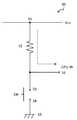
図7および図8によって、接続状態を示す信号の生成方法について説明する。 図7は、負論理回路で構成された判定信号発生回路のHレベル信号を発生する場合の簡略した回路図である。また、図8は負論理回路で構成された判定信号発生回路のLレベル信号を発生する場合の簡略した回路図である。 A method for generating a signal indicating a connection state will be described with reference to FIGS. FIG. 7 is a simplified circuit diagram in the case of generating an H level signal of the determination signal generation circuit configured with a negative logic circuit. FIG. 8 is a simplified circuit diagram in the case where an L level signal is generated by a determination signal generating circuit constituted by a negative logic circuit.
信号の生成を行う構成は、正論理回路によって構成する場合と、負論理回路によって構成する場合とがあるが、ここでは、接続されていない場合はHレベルの信号を、接続された時にはLレベルの信号を送出する負論理回路で説明する。The signal generation may be configured by a positive logic circuit or a negative logic circuit. Here, an H level signal is used when not connected, and an L level when connected. A negative logic circuit for transmitting the above signal will be described.
図7および図8に示す負論理回路50は、回路を動作させるために外部から電圧Vccを与えられている電気的基準点51と、プルアップ抵抗52と、論理回路用接続端子23と電気的に接続されている端子53と、論理回路用接続端子24と電気的に接続されている端子54と、接地回路と接続されている接地用端子55と、信号送出端子56によって構成されている。 The
図7は、電源プラグ1と電力受給体20とが接続されていない状態に相当する回路図である。すなわち、端子53と端子54とが電気的に解放された状態であるから、接地用端子55に向かって電流は流れず、かつ、信号送出端子56はプルアップ抵抗52を介して電圧Vccが与えられている基準点51と接続されているので、信号送出端子56は一定の電位を得る状態(Hレベルの信号を送出する状態)となる。 FIG. 7 is a circuit diagram corresponding to a state in which the power plug 1 and the
図8は、電源プラグ1と電力受給体20とが接続された状態に相当する。すなわち、端子53は論理回路用接続端子23および13、リード線16,論理回路用接続端子14および24を介して端子54とが電気的に接続された状態となる。よって、基準点51は、プルアップ抵抗52を介して接地用端子55と接続されることになり、接地用端子55に向かって電流が流れる状態となり、かつ、信号送出端子56の電位は接地用端子55とほぼ同じGNDレベルとなる。よって、信号送出端子56の電位の絶対値は、接続されていない状態の信号レベル(Hレベル)と比べて小さい状態(L0レベルの信号を送出する状態)となる。 FIG. 8 corresponds to a state in which the power plug 1 and the
これらの動作原理によって、電源プラグ1と、電力受給体2とが接続されると、電力受給体の判定信号発生回路の負論理回路では図7の状態から図8の状態となり、送出される信号の状態がHレベルからL0レベルへ変化するから、電力受給体では、この信号の変化を利用して、充電器はバッテリーに充電を開始する。 According to these operating principles, when the power plug 1 and the power receiver 2 are connected, the negative logic circuit of the determination signal generation circuit of the power receiver changes from the state of FIG. 7 to the state of FIG. Since the state changes from H level to L0 level, the power receiver uses this change in signal to start charging the battery.
なお、ここでは負論理回路50で構成された判定信号発生回路について説明をおこなったが、従来技術として正論理回路で構成された判定信号発生回路についても存在する(説明省略)。 Here, the determination signal generation circuit configured by the
また、従来技術として、電源供給状態を知らせるために、コネクタにおいて発光素子を設ける装置が存在する。 Further, as a conventional technique, there is an apparatus in which a light emitting element is provided in a connector in order to notify a power supply state.
例えば、特許文献2や特許文献3では、電源或いは信号供給時に接続部が有する発光素子によって、コネクタの一部が発光することで、電源或いは信号の供給状態を視認によって検知できるコネクタが開示されている。 For example, Patent Document 2 and Patent Document 3 disclose a connector that can detect the supply state of a power supply or a signal by visual recognition when a part of the connector emits light by a light emitting element included in a connection portion at the time of power supply or signal supply. Yes.
しかしながら、従来における特許文献1に示された技術では、電源供給がなされうる状態、もしくは、電源供給がされている状態であるのかが、装置の外観上では分からないという問題がある。 However, the conventional technique disclosed in Patent Document 1 has a problem in that it is not known from the appearance of the apparatus whether the power can be supplied or whether the power is supplied.
また、従来における特許文献2や特許文献3に示された技術では、発光素子が発光するための電力は、受給体に電力や信号を供給する側(供給側)から得ている。つまり、発光するための電源を、受給体への供給線(電源線)から直接得ている。このような場合、電源線の電圧が高かったり、電流が大きかったりすると、発光素子が壊れることがある。そこで発光素子が正常に動作できる程度の所望の値にまで、電圧を分圧したり、電流を分流する機能をコネクタに組み込む必要が生じ、分圧や分流のための回路が必要となるので、コネクタとして大きくなってしまうという問題があった。 Moreover, in the technique shown in the patent document 2 and the patent document 3 in the past, the electric power for a light emitting element to light-emit is obtained from the side (supply side) which supplies electric power and a signal to a receiving body. That is, a power source for emitting light is directly obtained from a supply line (power supply line) to the receiving body. In such a case, when the voltage of the power supply line is high or the current is large, the light emitting element may be broken. Therefore, it is necessary to divide the voltage to a desired value that allows the light emitting element to operate normally, or to incorporate a function for dividing the current into the connector, and a circuit for dividing or dividing the current is required. As a result, there was a problem of becoming larger.
そこで、本発明は以上のような従来存在した諸事情に鑑み創出されたもので、電源線から直接電力を供給させることなく発光素子を発光させ、もって、電源と受給体との電気的な接続状態を視認によって検知することが可能となる、小型で簡素な構造の電源プラグのコネクタを提供することを目的とする。 Therefore, the present invention was created in view of the conventional circumstances as described above, and causes the light emitting element to emit light without directly supplying power from the power supply line, thereby electrically connecting the power supply and the receiver. It is an object of the present invention to provide a connector for a power plug having a small and simple structure that can detect the state by visual recognition.
本発明に係るコネクタは、電源から、正論理回路または負論理回路を有する電力受給体に対して、電力を供給するための電気的な接続を行う電源プラグのコネクタにおいて、前記コネクタは、電源用接続端子と、接地用接続端子と、前記正論理回路または前記負論路回路と接続される2つの論理回路用接続端子とを有し、前記2つの論理回路用接続端子が、コネクタにおいて発光素子を介して接続されれて成る。これにより、前記発光素子が、電源受給体から供給される電力によって発光することを可能にすることで、上述した課題を解決した。 The connector according to the present invention is a connector of a power plug for performing electrical connection for supplying power from a power source to a power receiving body having a positive logic circuit or a negative logic circuit. A connection terminal; a ground connection terminal; and two logic circuit connection terminals connected to the positive logic circuit or the negative logic circuit, wherein the two logic circuit connection terminals are light emitting elements in the connector. Connected via. Thereby, the said light emitting element enabled it to light-emit with the electric power supplied from the power supply body, and solved the subject mentioned above.
また、発光素子を、発光ダイオードまたは有機電界発光素子とすることで、同じく上述した課題を解決した。 Moreover, the problem mentioned above was solved by making a light emitting element into a light emitting diode or an organic electroluminescent element.
さらに、コネクタ本体に光透過部を設けることで、同じく上述した課題を解決した。 Furthermore, the problem mentioned above was solved by providing the light transmission part in the connector main body.
本発明によれば、電源線から直接電力を供給させることなく電源プラグのコネクタに設けた発光素子を発光させることができるので、当該コネクタの電気的な接続構造を簡素なものとすることが可能となり、もって、当該コネクタを小型化できるようになる。また、電源と受給体との接続状態を視認によって知覚できるようになる。 According to the present invention, since the light emitting element provided in the connector of the power plug can emit light without supplying power directly from the power line, the electrical connection structure of the connector can be simplified. Thus, the connector can be miniaturized. Further, the connection state between the power source and the receiver can be perceived by visual recognition.
以下に、本発明を実施するための最良の形態を、図面を参照して説明する。 The best mode for carrying out the present invention will be described below with reference to the drawings.
本発明に係るコネクタは、図1に示すように、論理回路用接続端子13と14とを接続するリード線16に、発光素子17を設けている。また、発光素子の発光を外部から視認できるように、図に示すように受給側コネクタ本体18に光透過部19を設けている。 As shown in FIG. 1, the connector according to the present invention is provided with a
本実施の形態では、光透過部19は、図2のように、受給側コネクタ本体18の側面の一部に穴を開けて、発光素子17を差込み、受給側コネクタ本体18と、発光素子17とをハンダ19Aで固定することで、外部から視認できるように設置した。なお、固定法方法は接着剤によってもかまわない。 In the present embodiment, as shown in FIG. 2, the
このような構成において、電源プラグ1と電力受給体2とが接続されていない場合は、電力受給体2に備わる負論理回路50では、従来の状態と同じように、端子53と端子54とが電気的に切断された状態を示すHレベルの信号が信号送出端子56に発生する。 In such a configuration, when the power plug 1 and the power receiver 2 are not connected, in the
次に、電源プラグ1と電力受給体20とが接続された状態では、端子53は論理回路用接続端子23および13、リード線16,発光素子17、論理回路用接続端子14および24を介して端子54とが電気的に接続された状態となる。よって、基準点51は、プルアップ抵抗52、発光素子17を介して接地用端子55と接続されることになるため、接地用端子55に向かって電気が流れ、発光素子17が発光する。 Next, in a state where the power plug 1 and the
一方、信号送出端子56の電位の絶対値は、接続されていない状態の信号レベル(Hレベル)と比べて小さい状態(L1レベルの信号を送出する状態)に変化する。電力受給体2では、この信号の変化を利用して、接続状態を把握し、バッテリーに充電を開始する。 On the other hand, the absolute value of the potential of the
なお、L1レベルをL0レベルに近づけるようにすると、電源プラグ1と電力受給体2との接続の有無による信号レベルの差が大きくなり、接続状態を判定しやすくなるのでより好ましい。ここで、L1レベルをL0レベルに近づけるには、発光素子17の内部抵抗をより小さいものを選択すればよい。 In addition, it is more preferable to make the L1 level close to the L0 level because a difference in signal level depending on the presence / absence of connection between the power plug 1 and the power receiving body 2 becomes large and the connection state can be easily determined. Here, in order to bring the L1 level closer to the L0 level, a
なお、説明では負論理回路50によって説明したが、正論理回路でも同様に信号の変化(L1レベルからHレベルへ)が発生するので、この信号の変化を利用すれば接続状態が把握できる。 In the description, the
このようにして、電源プラグ1と、電力受給体2とが接続されると、電源側の供給線から直接電力を供給させるのではなく、電力受給体2の内部にある負論理回路50に与えた電圧Vccにより、電源プラグ1の受給側コネクタ10に内蔵された発光素子17が発光するとともに、発光によって接続状態であることを視認できるようになる。 When the power plug 1 and the power receiving body 2 are connected in this way, power is not supplied directly from the power supply side supply line but is supplied to the
光透過部19の構成について、他の態様としては、図3のように、発光素子17を受給側コネクタ本体18の内部に設置し、受給側コネクタ本体18の側面の一部に視認用の窓(本実施例では受給側コネクタ本体18の側面の長手方向を長軸側とした楕円形の窓としているが形状にはこだわらない)を設けるようにしてもよい。 As another aspect of the configuration of the
更に他の態様としては、図4のように、受給側コネクタ本体18の一部を外周方向全てにわたって光透過性のある素材19Bとする構成としても、組み立てや加工がしやすいので好ましい。 As another embodiment, as shown in FIG. 4, a configuration in which a part of the receiving-side connector
本発明に係る接続コネクタは、例えば、電源と電気自動車へのプラグインハイブリッド車への電力供給において、接続状態を視認するために幅広く利用することができる。 The connection connector according to the present invention can be widely used for visually confirming a connection state, for example, in power supply to a plug-in hybrid vehicle to a power source and an electric vehicle.
1…電源プラグ
10…受給側コネクタ
11、12…電源用接続端子
13、14…論理回路用接続端子
15…接地用接続端子
16…リード線
17…発光素子
18…受給側コネクタ本体
19…光透過部
20…電力受給体
21、22…電源用接続端子
23、24…論理回路用接続端子
25…接地用接続端子
30…電源側コネクタ
31、32…電源用接続端子
33…接地用接続端子
40…リード部
41,42,42…リード線
50…負論理回路
51…電気的基準点
52…プルアップ抵抗
53,54…端子
55…接地用端子
56…信号送出端子DESCRIPTION OF SYMBOLS 1 ...
Claims (3)
Translated fromJapanese前記コネクタは、電源用接続端子と、
接地用接続端子と、
前記正論理回路または前記負論路回路と接続される2つの論理回路用接続端子と、
を有し、
前記2つの論理回路用接続端子が、コネクタにおいて発光素子を介して接続されること
を特徴とするコネクタ。In a power plug connector that performs electrical connection to supply power from a power source to a power receiver having a positive logic circuit or a negative logic circuit,
The connector includes a power connection terminal,
A ground connection terminal;
Two logic circuit connection terminals connected to the positive logic circuit or the negative logic circuit;
Have
The two logic circuit connection terminals are connected to each other through a light emitting element in the connector.
を特徴とする請求項1記載のコネクタ。The connector according to claim 1, wherein the light emitting element is a light emitting diode or an organic electroluminescent element.
を特徴とした、請求項1または請求項2に記載のコネクタ。The connector according to claim 1, wherein the connector main body is provided with a light transmission portion.
Priority Applications (1)
| Application Number | Priority Date | Filing Date | Title |
|---|---|---|---|
| JP2007178245AJP2009016241A (en) | 2007-07-06 | 2007-07-06 | Power plug connector |
Applications Claiming Priority (1)
| Application Number | Priority Date | Filing Date | Title |
|---|---|---|---|
| JP2007178245AJP2009016241A (en) | 2007-07-06 | 2007-07-06 | Power plug connector |
Publications (1)
| Publication Number | Publication Date |
|---|---|
| JP2009016241Atrue JP2009016241A (en) | 2009-01-22 |
Family
ID=40356889
Family Applications (1)
| Application Number | Title | Priority Date | Filing Date |
|---|---|---|---|
| JP2007178245APendingJP2009016241A (en) | 2007-07-06 | 2007-07-06 | Power plug connector |
Country Status (1)
| Country | Link |
|---|---|
| JP (1) | JP2009016241A (en) |
Citations (3)
| Publication number | Priority date | Publication date | Assignee | Title |
|---|---|---|---|---|
| JPH02144867A (en)* | 1988-11-24 | 1990-06-04 | Nec Corp | Package with contact for judging incomplete fitting |
| JPH06325830A (en)* | 1993-05-10 | 1994-11-25 | Sumitomo Wiring Syst Ltd | Charging connector for electric automobile |
| JP2001347701A (en)* | 2000-06-09 | 2001-12-18 | Fuji Photo Film Co Ltd | Exposing unit |
- 2007
- 2007-07-06JPJP2007178245Apatent/JP2009016241A/enactivePending
Patent Citations (3)
| Publication number | Priority date | Publication date | Assignee | Title |
|---|---|---|---|---|
| JPH02144867A (en)* | 1988-11-24 | 1990-06-04 | Nec Corp | Package with contact for judging incomplete fitting |
| JPH06325830A (en)* | 1993-05-10 | 1994-11-25 | Sumitomo Wiring Syst Ltd | Charging connector for electric automobile |
| JP2001347701A (en)* | 2000-06-09 | 2001-12-18 | Fuji Photo Film Co Ltd | Exposing unit |
Similar Documents
| Publication | Publication Date | Title |
|---|---|---|
| US10017137B2 (en) | Vehicle-mounted system and wire harness | |
| US9932002B2 (en) | Seat control system and wire harness | |
| JP2016039147A (en) | Charging plug, charging cable and charging method for electric vehicle | |
| US7471012B2 (en) | Power supply apparatus for vehicle | |
| CN102844512B (en) | Door handle with passive access control and lighting components | |
| US20130285549A1 (en) | Wire harness assembly and lighting unit | |
| EP2730465A1 (en) | Wire harness structure and electronic control unit | |
| JP5206388B2 (en) | Plug-in vehicle charging system and charging control device | |
| CN104608639B (en) | A kind of pure electric automobile high-tension connector | |
| CN104113422A (en) | Communication apparatus | |
| CN108351628A (en) | Distributing switch | |
| CN110979207B (en) | Wire harness | |
| CN107017525B (en) | Receiving confirmation construction, electric circuit connection container and the harness of electronic component | |
| JP2013538722A (en) | Electric circuit and method of manufacturing the electric circuit | |
| JP7058734B2 (en) | Engine starter and its manufacturing method | |
| JP2009016241A (en) | Power plug connector | |
| CN108886219A (en) | Connectors, connection status detection systems, and terminals | |
| US10326442B2 (en) | Assembly having internally configurable solid-state switch arrangement for use as one or more disconnection switches in electrical systems and having external package common to the electrical systems | |
| US8669737B2 (en) | Courtesy light for an electrical charging system | |
| US9553464B2 (en) | In-vehicle-mounted charging device | |
| CN209764117U (en) | Sensor and vehicle | |
| US20120091926A1 (en) | Electronic speed controller apparatus with signal dividing port device and control method thereof | |
| KR20170034167A (en) | Apparatus for supplying always on electric power using a fuse box coaver with socket outlets | |
| US20200267821A1 (en) | Circuit assembly of a lighting unit of a headlight for a vehicle | |
| CN200941112Y (en) | Combined electrician meter for automobile maintenance |
Legal Events
| Date | Code | Title | Description |
|---|---|---|---|
| A621 | Written request for application examination | Effective date:20100706 Free format text:JAPANESE INTERMEDIATE CODE: A621 | |
| A977 | Report on retrieval | Free format text:JAPANESE INTERMEDIATE CODE: A971007 Effective date:20120302 | |
| A131 | Notification of reasons for refusal | Effective date:20120330 Free format text:JAPANESE INTERMEDIATE CODE: A131 | |
| A02 | Decision of refusal | Free format text:JAPANESE INTERMEDIATE CODE: A02 Effective date:20120803 |