JP2009015611A - Charging system, charging unit, and system for automatically charging moving robot - Google Patents
Charging system, charging unit, and system for automatically charging moving robotDownload PDFInfo
- Publication number
- JP2009015611A JP2009015611AJP2007176965AJP2007176965AJP2009015611AJP 2009015611 AJP2009015611 AJP 2009015611AJP 2007176965 AJP2007176965 AJP 2007176965AJP 2007176965 AJP2007176965 AJP 2007176965AJP 2009015611 AJP2009015611 AJP 2009015611A
- Authority
- JP
- Japan
- Prior art keywords
- connection terminal
- slide
- robot
- terminals
- terminal portion
- Prior art date
- Legal status (The legal status is an assumption and is not a legal conclusion. Google has not performed a legal analysis and makes no representation as to the accuracy of the status listed.)
- Pending
Links
- 238000001514detection methodMethods0.000claimsabstractdescription31
- 238000006073displacement reactionMethods0.000claimsdescription23
- 238000000034methodMethods0.000abstractdescription9
- 238000013459approachMethods0.000abstractdescription6
- 230000008878couplingEffects0.000abstract1
- 238000010168coupling processMethods0.000abstract1
- 238000005859coupling reactionMethods0.000abstract1
- 239000000428dustSubstances0.000description87
- 238000004140cleaningMethods0.000description80
- 230000001276controlling effectEffects0.000description5
- 238000012986modificationMethods0.000description5
- 230000004048modificationEffects0.000description5
- 238000007796conventional methodMethods0.000description3
- 230000003028elevating effectEffects0.000description3
- 230000005540biological transmissionEffects0.000description2
- 238000010408sweepingMethods0.000description2
- 230000001174ascending effectEffects0.000description1
- 238000012937correctionMethods0.000description1
- 238000010586diagramMethods0.000description1
- 238000005516engineering processMethods0.000description1
- 230000014509gene expressionEffects0.000description1
- 238000003384imaging methodMethods0.000description1
- 238000011065in-situ storageMethods0.000description1
- 238000005259measurementMethods0.000description1
- 230000002265preventionEffects0.000description1
- 230000001105regulatory effectEffects0.000description1
- 230000008054signal transmissionEffects0.000description1
- 230000002269spontaneous effectEffects0.000description1
Images


Classifications
- G—PHYSICS
- G05—CONTROLLING; REGULATING
- G05D—SYSTEMS FOR CONTROLLING OR REGULATING NON-ELECTRIC VARIABLES
- G05D1/00—Control of position, course, altitude or attitude of land, water, air or space vehicles, e.g. using automatic pilots
- G05D1/02—Control of position or course in two dimensions
- G05D1/021—Control of position or course in two dimensions specially adapted to land vehicles
- G05D1/0255—Control of position or course in two dimensions specially adapted to land vehicles using acoustic signals, e.g. ultra-sonic singals
- G—PHYSICS
- G05—CONTROLLING; REGULATING
- G05D—SYSTEMS FOR CONTROLLING OR REGULATING NON-ELECTRIC VARIABLES
- G05D1/00—Control of position, course, altitude or attitude of land, water, air or space vehicles, e.g. using automatic pilots
- G05D1/02—Control of position or course in two dimensions
- G05D1/021—Control of position or course in two dimensions specially adapted to land vehicles
- G05D1/0212—Control of position or course in two dimensions specially adapted to land vehicles with means for defining a desired trajectory
- G05D1/0225—Control of position or course in two dimensions specially adapted to land vehicles with means for defining a desired trajectory involving docking at a fixed facility, e.g. base station or loading bay
Landscapes
- Engineering & Computer Science (AREA)
- Remote Sensing (AREA)
- Physics & Mathematics (AREA)
- Radar, Positioning & Navigation (AREA)
- General Physics & Mathematics (AREA)
- Aviation & Aerospace Engineering (AREA)
- Automation & Control Theory (AREA)
- Acoustics & Sound (AREA)
- Electric Propulsion And Braking For Vehicles (AREA)
- Control Of Position, Course, Altitude, Or Attitude Of Moving Bodies (AREA)
- Electric Vacuum Cleaner (AREA)
- Connector Housings Or Holding Contact Members (AREA)
- Charge And Discharge Circuits For Batteries Or The Like (AREA)
Abstract
Description
Translated fromJapanese本発明は、移動ロボットにおける充電システム、充電ユニットおよび自動充電システムに関するものである。 The present invention relates to a charging system, a charging unit, and an automatic charging system in a mobile robot.
本発明に係る従来技術として、移動ロボットが充電ステーションに自動的に帰還して、自動的に充電を行う様々な技術が提案されている(特許文献1〜3参照)。
前記特許文献1では、発信方向ごとに異なる信号パターンを有する指向性の探索信号を充電ステーションから移動ロボットに発信することにより、自動充電ステーションに対する移動ロボットの位置と方向を認識させて、充電ステーションに誘導している。
前記特許文献2では、複数のRFIDタグに充電ステーションの位置情報を記憶させて各所に配設し、それを移動ロボットに読み取らせることで充電ステーションに帰還させている。更に別の発明としては、撮像手段を用いた誘導手段等の従来技術が提案されている。In
In
しかし、これらのような従来技術では、各種センサの精度誤差や移動ロボットの制御動作の精度誤差により、移動ロボットを充電ステーションの近傍にまで帰還させることはできるが、移動ロボットと充電ステーションとの接続端子とを精度良く結合させることは技術的に困難であった。 However, in the conventional techniques such as these, the mobile robot can be returned to the vicinity of the charging station due to the accuracy error of various sensors and the control error of the mobile robot, but the connection between the mobile robot and the charging station is not possible. It was technically difficult to connect the terminals with high accuracy.
そのため、この問題を解決するための従来技術として、移動ロボットと充電ステーションとの位置ズレが許容できるように幅広の充電接続面に用いたものがある。しかし、これでは接続面が大きく、複数のバッテリーを同時に充電させるための端子数を増やすことはできない。 For this reason, as a conventional technique for solving this problem, there is a technique used on a wide charging connection surface so that a positional deviation between the mobile robot and the charging station is allowed. However, this has a large connection surface, and the number of terminals for charging a plurality of batteries simultaneously cannot be increased.
一方、特許文献3では、移動ロボットが充電ステーションに進入してきた時に、充電ステーションの前方の床面に配設したアイドラローラで移動ロボットの進入角度のズレを修正する手段が提示されている。しかし、この技術では進入角度のズレは修正できるが、横方向の位置ズレを修正することはできず、接続端子を精度良く接続できないという問題が残っている。 On the other hand,
したがって、本発明の主目的は、移動ロボットの測距センサの精度誤差や走行制御動作の精度誤差などにより、充電ステーションに対して移動ロボットが帰還した時の位置ズレや進入角度ズレがあっても、充電用の接点同士が精度良く結合することができる技術を提供するものである。 Therefore, the main object of the present invention is to prevent positional deviation and approach angle deviation when the mobile robot returns to the charging station due to accuracy error of the distance measuring sensor of the mobile robot or accuracy error of the traveling control operation. The present invention provides a technique capable of accurately connecting charging contacts.
さらに、本発明の他の目的は、移動ロボット側の接続端子および充電ステーション側の接続端子が、人の手などに触れることによって感電したり、ホコリ等によって漏電を生じたりするのを防止するための技術を提供するものである。 Furthermore, another object of the present invention is to prevent the connection terminal on the mobile robot side and the connection terminal on the charging station from receiving an electric shock by touching a human hand or the like, or causing leakage due to dust or the like. Technology.
前記目的を達成するために、本発明の充電システムは、バッテリからの電力で走行車輪を回転させて床面を走行する移動ロボットと、床面もしくは壁面等に設置された充電ユニットとを備え、前記充電ユニットを介して前記バッテリの充電を行う充電システムであって、前記ロボットに設けられ複数の端子を有する第1接続端子部と、前記充電ユニットに設けられ、前記各端子に接続される複数の端子を有する第2接続端子部と、前記充電ユニットの第2接続端子部に前記ロボットの前記第1接続端子部が対面した状態となるように、前記ロボットの走行を制御する走行制御手段と、前記第1または第2接続端子部の一方をロボットの走行方向に直交する横方向にスライド移動可能に支持するスライド支持手段と、前記スライド支持手段によりスライド移動可能に支持された接続端子部を前記横方向にスライド移動させるスライド駆動手段と、前記第1接続端子部と第2接続端子部との前記横方向のズレを検出するズレ検出手段と、前記検出されたズレに基づいて前記スライド駆動手段を駆動して前記2つの端子部のズレを修正するスライド制御手段と、前記第1または第2接続端子部の端子を前記横方向に直交する方向に突出退避可能に支持する端子支持手段と、前記端子支持手段により突出可能に支持された端子を前記突出退避方向に進退させる進退駆動手段と、前記両端子部が互いに対面し、かつ、本質的に前記ズレがない状態または修正された状態で、前記進退駆動手段により前記端子を突出させて前記両端子を互いに接続させる接続制御手段とを備えている。 In order to achieve the above object, a charging system of the present invention includes a mobile robot that travels on a floor surface by rotating a traveling wheel with electric power from a battery, and a charging unit installed on the floor surface or a wall surface. A charging system for charging the battery via the charging unit, wherein the robot is provided with a first connection terminal portion having a plurality of terminals, a plurality of terminals provided in the charging unit and connected to the terminals. A second connection terminal portion having a terminal, and a travel control means for controlling the travel of the robot such that the first connection terminal portion of the robot faces the second connection terminal portion of the charging unit. A slide support means for slidably supporting one of the first or second connection terminal portions in a lateral direction perpendicular to the traveling direction of the robot, and the slide support means. A slide driving means for slidingly moving the connection terminal portion supported so as to be slidable in the lateral direction; a displacement detection means for detecting the lateral displacement between the first connection terminal portion and the second connection terminal portion; A slide control means for driving the slide drive means based on the detected deviation to correct the deviation between the two terminal portions, and a direction orthogonal to the lateral direction of the terminals of the first or second connection terminal portions A terminal support means for supporting the terminal so as to be able to project and retract, an advance / retreat driving means for advancing and retracting the terminal supported so as to project by the terminal support means in the projecting and retracting direction, and both the terminal portions face each other, and essentially Connection control means for projecting the terminal by the advance / retreat driving means to connect the two terminals to each other in a state in which there is no deviation or correction.
本発明によれば、ズレ検出手段により検出されたズレに基づいて、第1または第2接続端子部の一方をロボットの走行方向に直交する横方向にスライド移動させることにより、2つの端子部のズレを修正することにより、充電ステーションに対して移動ロボットが帰還した時の位置ズレや進入角度ズレがあっても、充電用の接点を位置精度良く結合させることができる。 According to the present invention, based on the displacement detected by the displacement detection means, one of the first or second connection terminal portions is slid in the lateral direction perpendicular to the traveling direction of the robot, thereby causing the two terminal portions to move. By correcting the misalignment, the charging contacts can be coupled with high positional accuracy even if there is a misalignment or an approach angle misalignment when the mobile robot returns to the charging station.
また、第1または第2接続端子部の端子が前記横方向に直交する方向に突出退避可能に設定されていると共に、本質的にズレがない状態または修正された状態で、前記端子を突出させて前記両端子を互いに接続させるので、人の手が触れることによる感電やホコリ等による漏電を防止することができる。 Further, the terminal of the first or second connection terminal portion is set so as to be able to protrude and retract in a direction orthogonal to the lateral direction, and the terminal is protruded in a state where there is essentially no deviation or in a corrected state. Thus, both terminals are connected to each other, so that it is possible to prevent an electric shock due to a human hand touching or a leakage due to dust or the like.
本発明において、前記スライド支持手段が前記ロボットに設けられ、前記ロボットの走行部に対し前記スライド支持手段を介してスライド移動可能なスライド部に前記第1接続端子部が設けられていてもよい。
かかる態様によれば、前記ロボットに設けられたスライド部をスライドさせることにより、第2接続端子部に対して第1接続端子部を接続することができる。In this invention, the said slide support means may be provided in the said robot, and the said 1st connection terminal part may be provided in the slide part which can be slid with respect to the running part of the said robot via the said slide support means.
According to this aspect, the first connection terminal portion can be connected to the second connection terminal portion by sliding the slide portion provided in the robot.
本発明において、前記スライド部には、所定の作業を行う作業部が設けられていてもよい。前記スライド部に設ける作業部としては、たとえば、清掃ロボットの場合には、床面のゴミの集塵や清拭を行う機能を設けることができる。 In the present invention, the slide part may be provided with a work part for performing a predetermined work. For example, in the case of a cleaning robot, the working unit provided on the slide unit can be provided with a function of collecting and cleaning dust on the floor surface.
本発明において、前記端子支持手段が前記充電ユニットに設けられていてもよい。 In the present invention, the terminal support means may be provided in the charging unit.
本発明において、前記2つの端子部が互いに平行となった状態で対面しているか否かを検出する傾き検出手段を更に備え、前記走行制御手段は、前記傾き検出手段で検出された傾きに基づいて前記ロボットを回転させて前記2つの端子部が互いに平行となるように前記ロボットの姿勢を制御するようにすれば、より一層、正確に両端子部を接続することができる。 In the present invention, there is further provided an inclination detecting means for detecting whether or not the two terminal portions face each other in a parallel state, and the travel control means is based on the inclination detected by the inclination detecting means. If the robot is rotated so that the posture of the robot is controlled so that the two terminal portions are parallel to each other, the two terminal portions can be more accurately connected.
本発明において、バッテリからの電力で走行車輪を回転させて床面を走行する移動ロボットと、床面もしくは壁面等に設置された充電ユニットとを備え、前記充電ユニットを介して前記バッテリの充電を行う充電システムであって、前記ロボットに設けられ複数の端子を有する第1接続端子部と、前記充電ユニットに設けられ、前記各端子に接続される複数の端子を有する第2接続端子部と、前記充電ユニットの第2接続端子部に前記ロボットの前記第1接続端子部が対面した状態となるように、前記ロボットの走行を制御する走行制御手段と、前記第1または第2接続端子部の端子を前記横方向に直交する方向に突出退避可能に支持する端子支持手段と、前記端子支持手段により突出可能に支持された端子を前記突出退避方向に進退させる進退駆動手段と、前記両端子部が互いに対面した状態状態で、前記進退駆動手段により前記端子を突出させて前記両端子を互いに接続させる接続制御手段とを備えていてもよい。 In the present invention, a mobile robot that travels on a floor surface by rotating a traveling wheel with electric power from a battery, and a charging unit installed on the floor surface or a wall surface, the battery is charged via the charging unit. A charging system for performing a first connection terminal portion provided on the robot and having a plurality of terminals; a second connection terminal portion provided on the charging unit and having a plurality of terminals connected to the terminals; A travel control means for controlling the travel of the robot such that the first connection terminal portion of the robot faces the second connection terminal portion of the charging unit; and the first or second connection terminal portion Terminal support means for supporting the terminal so that it can protrude and retract in a direction orthogonal to the lateral direction, and a terminal supported so as to be able to protrude by the terminal support means are advanced and retracted in the protrusion and retract direction. A retraction drive means, said while the state in which both terminal portions facing each other, may be provided with a connection control means for connecting together the two terminals is protruded to the terminal by the advancing drive means.
本発明において、バッテリからの電力で走行車輪を回転させて床面を走行する移動ロボットと、床面もしくは壁面等に設置された充電ユニットとを備え、前記充電ユニットを介して前記バッテリの充電を行う充電システムであって、前記ロボットに設けられ複数の端子を有する第1接続端子部と、前記充電ユニットに設けられ、前記各端子に接続される複数の端子を有する第2接続端子部と、前記充電ユニットの第2接続端子部に前記ロボットの前記第1接続端子部が対面した状態となるように、前記ロボットの走行を制御する走行制御手段と、前記第1または第2接続端子部の一方をロボットの走行方向に直交する横方向にスライド移動可能に支持するスライド支持手段と、前記スライド支持手段によりスライド移動可能に支持された接続端子部を前記横方向にスライド移動させるスライド駆動手段と、前記第1接続端子部と第2接続端子部との前記横方向のズレを検出するズレ検出手段と、前記検出されたズレに基づいて前記スライド駆動手段を駆動して前記2つの端子部のズレを修正するスライド制御手段と、前記両端子部が互いに対面し、かつ、本質的に前記ズレがない状態または修正された状態で、前記一方の端子を他方の端子に向って前進させて前記両端子を互いに接続させる接続制御手段とを備えていてもよい。 In the present invention, a mobile robot that travels on a floor surface by rotating a traveling wheel with electric power from a battery, and a charging unit installed on the floor surface or a wall surface, the battery is charged via the charging unit. A charging system for performing a first connection terminal portion provided on the robot and having a plurality of terminals; a second connection terminal portion provided on the charging unit and having a plurality of terminals connected to the terminals; A travel control means for controlling the travel of the robot such that the first connection terminal portion of the robot faces the second connection terminal portion of the charging unit; and the first or second connection terminal portion Slide support means for supporting one of the slides in a lateral direction perpendicular to the traveling direction of the robot, and a connection supported to be slidable by the slide support means Based on the detected displacement, slide drive means for sliding the child portion in the lateral direction, displacement detection means for detecting the lateral displacement between the first connection terminal portion and the second connection terminal portion, and The slide control means for driving the slide driving means to correct the deviation between the two terminal portions, the both terminal portions facing each other, and the state in which the deviation is essentially absent or corrected, Connection control means for advancing one terminal toward the other terminal and connecting the two terminals to each other may be provided.
本発明において、バッテリからの電力で走行車輪を回転させて床面を走行する移動ロボットに、床面もしくは壁面等に設置された充電ユニットを介して前記バッテリの充電を行う充電ユニットであって、前記ロボットに設けられた第1接続端子部の複数の各端子に接続される複数の端子を有する第2接続端子部と、前記第2接続端子部をロボットの走行方向に直交する横方向にスライド移動可能に支持するスライド支持手段と、前記第2接続端子部を前記横方向にスライド移動させるスライド駆動手段と、前記第1接続端子部と第2接続端子部との前記横方向のズレを検出するズレ検出手段と、前記検出されたズレに基づいて前記スライド駆動手段を駆動して前記2つの端子部のズレを修正するスライド制御手段と、前記第2接続端子部の端子を前記横方向に直交する方向に突出退避可能に支持する端子支持手段と、前記端子支持手段により突出可能に支持された端子を前記突出退避方向に進退させる進退駆動手段と、前記両端子部が互いに対面し、かつ、本質的に前記ズレがない状態または修正された状態で、前記進退駆動手段により前記第2接続端子部の端子を突出させて前記両端子を互いに接続させる接続制御手段とを備えていてもよい。 In the present invention, a charging unit that charges the battery via a charging unit installed on a floor surface or a wall surface to a mobile robot that travels on the floor surface by rotating traveling wheels with electric power from the battery, A second connection terminal portion having a plurality of terminals connected to a plurality of terminals of the first connection terminal portion provided on the robot; and the second connection terminal portion is slid in a lateral direction perpendicular to the traveling direction of the robot. Detecting the lateral displacement between the slide support means for movably supporting, the slide drive means for slidingly moving the second connection terminal portion in the lateral direction, and the first connection terminal portion and the second connection terminal portion. A displacement detecting means for performing the operation, a slide control means for driving the slide driving means based on the detected displacement to correct a displacement between the two terminal portions, and an end of the second connection terminal portion Terminal support means for supporting the terminal so as to be able to project and retract in a direction orthogonal to the lateral direction, advancing and retracting driving means for allowing the terminal supported by the terminal support means to project and retract in the projecting and retracting direction, and the both terminal portions. Connection control means for causing the terminals of the second connection terminal portion to project by the advancing / retreating driving means so as to connect the two terminals to each other in a state where they face each other and are essentially free of the deviation or are corrected. You may have.
本発明において、バッテリからの電力で走行車輪を回転させて床面を走行する移動ロボットに、床面もしくは壁面等に設置された充電ユニットを介して前記バッテリの充電を行う充電ユニットであって、前記ロボットに設けられた第1接続端子部の複数の各端子に接続される複数の端子を有する第2接続端子部と、前記第2接続端子部の端子を前記横方向に直交する方向に突出退避可能に支持する端子支持手段と、前記端子支持手段により突出可能に支持された端子を前記突出退避方向に進退させる進退駆動手段と、前記両端子部が互いに対面し、かつ、本質的に前記ズレがない状態または修正された状態で、前記進退駆動手段により前記第2接続端子部の端子を突出させて前記両端子を互いに接続させる接続制御手段とを備えていてもよい。 In the present invention, a charging unit that charges the battery via a charging unit installed on a floor surface or a wall surface to a mobile robot that travels on the floor surface by rotating traveling wheels with electric power from the battery, A second connection terminal portion having a plurality of terminals connected to a plurality of terminals of the first connection terminal portion provided in the robot, and a terminal of the second connection terminal portion project in a direction orthogonal to the lateral direction. The terminal support means for removably supporting, the advancing / retreating drive means for advancing / retreating the terminal supported by the terminal support means in a projecting and retracting direction, the both terminal portions face each other, and essentially the above There may be provided connection control means for projecting the terminals of the second connection terminal portion by the advance / retreat driving means to connect the both terminals to each other in a state where there is no deviation or in a corrected state.
本発明において、バッテリからの電力で走行車輪を回転させて床面を走行する移動ロボットに、床面もしくは壁面等に設置された充電ユニットを介して前記バッテリの充電を行う充電ユニットであって、前記ロボットに設けられた第1接続端子部の複数の各端子に接続される複数の端子を有する第2接続端子部と、前記第2接続端子部をロボットの走行方向に直交する横方向にスライド移動可能に支持するスライド支持手段と、前記第2接続端子部を前記横方向にスライド移動させるスライド駆動手段と、前記第1接続端子部と第2接続端子部との前記横方向のズレを検出するズレ検出手段と、前記検出されたズレに基づいて前記スライド駆動手段を駆動して前記2つの端子部のズレを修正するスライド制御手段と、前記両端子部が互いに対面し、かつ、本質的に前記ズレがない状態または修正された状態で、前記一方の端子を他方の端子に向って前進させて前記両端子を互いに接続させる接続制御手段とを備えていてもよい。 In the present invention, a charging unit that charges the battery via a charging unit installed on a floor surface or a wall surface to a mobile robot that travels on the floor surface by rotating traveling wheels with electric power from the battery, A second connection terminal portion having a plurality of terminals connected to a plurality of terminals of the first connection terminal portion provided on the robot; and the second connection terminal portion is slid in a lateral direction perpendicular to the traveling direction of the robot. Detecting the lateral displacement between the slide support means for movably supporting, the slide drive means for slidingly moving the second connection terminal portion in the lateral direction, and the first connection terminal portion and the second connection terminal portion. A shift detecting means for driving, a slide control means for driving the slide driving means based on the detected shift to correct a shift between the two terminal portions, and the two terminal portions are mutually opposed. And connection control means for advancing the one terminal toward the other terminal so as to connect the two terminals to each other in a state in which there is essentially no deviation or in a corrected state. .
本発明における移動ロボットの自動充電システムにおいて、バッテリで床面を走行可能な移動ロボットと、床面に設置されて該移動ロボットのバッテリを充電するための充電ユニットとを備え、前記移動ロボットは、バッテリを搭載し、走行車輪を有する走行部と走行部に対してスライド駆動モータで横方向にスライド移動可能なスライド部とを備え、前記スライド部は、該スライド部のスライド方向から近接する物体を検知するための一対の側面物体検知センサと、前記スライド方向に垂直な方向から近接する物体を検知するための後面物体検知センサと、前記バッテリを充電するための複数の第一接続端子とを備え、前記充電ユニットには、前記充電ユニットの前面から前方に突出し、前記スライド部の幅と同等または若干広い幅で、前記スライド部を挟み込む形状一対のガイド部と、前記第一接続端子に対応した位置に設けられた複数の第二接続端子とを備え、前記移動ロボットの前記スライド部が前記充電ユニットに対面した状態で走行している際に、前記充電ユニットの前記ガイド部を一方の前記側面物体検知センサが検知した時には、当該一方の前記センサが前記ガイド部を検知しなくなる方向に前記スライド部をスライドさせ、前記充電ユニットを前記後面物体検知センサが検知した時は、前記移動ロボットの走行動作と前記スライド部のスライド動作とを停止させて、前記第一接続端子を前記第二接続端子に電気的に接続させる接続制御手段を設けてもよい。 In the automatic charging system for a mobile robot according to the present invention, the mobile robot includes a mobile robot capable of traveling on a floor surface with a battery, and a charging unit installed on the floor surface for charging the battery of the mobile robot, A traveling part having a battery and having traveling wheels, and a sliding part that can be slid laterally by a slide drive motor with respect to the traveling part, the sliding part is configured to remove an object close to the sliding direction of the sliding part. A pair of side object detection sensors for detecting, a rear object detection sensor for detecting an object approaching from a direction perpendicular to the sliding direction, and a plurality of first connection terminals for charging the battery. The charging unit protrudes forward from the front surface of the charging unit and has a width equal to or slightly wider than the width of the slide portion. A pair of guide portions sandwiching the slide portion and a plurality of second connection terminals provided at positions corresponding to the first connection terminals, with the slide portion of the mobile robot facing the charging unit When one of the side object detection sensors detects the guide part of the charging unit while traveling, the slide part is slid in a direction in which the one sensor does not detect the guide part, When the rear object detection sensor detects the charging unit, the traveling operation of the mobile robot and the sliding operation of the slide portion are stopped, and the first connection terminal is electrically connected to the second connection terminal. Connection control means may be provided.
発明の概要:
本発明の移動ロボットは、例えば、バッテリ駆動で床面を移動し、床面のゴミの集塵や清拭作業等を行うような清掃ロボットと、そのバッテリを自動で充電するための充電ステーションに係るものである。Summary of the invention:
The mobile robot of the present invention is, for example, a cleaning robot that moves on a floor surface driven by a battery and collects dust on the floor surface, or performs a wiping operation, and a charging station for automatically charging the battery. It is concerned.
ただし、ゴミの集塵作業を行う清掃ロボットを例示して、以下、具体的に説明するが、移動ロボットは、清掃ロボットに限定されるものではなく、たとえば、警備ロボットや案内ロボットなどの床面上を走行するものであればよい。 However, a cleaning robot that performs dust collection work will be exemplified and will be described in detail below. However, the mobile robot is not limited to the cleaning robot, for example, a floor surface of a security robot, a guide robot, or the like. Anything that travels above is acceptable.
前記清掃ロボットの走行部は、バッテリを搭載し、左右に独立駆動車輪と前後に自在キャスタで直進走行、カーブ走行、その場回転を行うことができる走行部を有し、走行部の後ろ側には床面のゴミを回転ブラシで掃きながら吸い込むための集塵作業部を脱着可能に配設されている。走行部の上側には、集塵作業部で床面のゴミを吸い上げるためのバキューム装置を内蔵してゴミを溜めるための集塵タンク部が脱着可能に配設されている。 The traveling part of the cleaning robot is equipped with a battery, and has a traveling part that can perform straight traveling, curve traveling, and in-situ rotation with independent drive wheels on the left and right and front and rear casters, and behind the traveling part. Is provided with a dust collecting work part for detaching the dust on the floor surface while sweeping it with a rotating brush. On the upper side of the traveling unit, a vacuum collecting device for sucking up dust on the floor surface in the dust collecting working unit is built in, and a dust collecting tank unit for collecting the dust is detachably disposed.
更に、清掃ロボットを充電ステーションに帰還させるために、走行部にリモート信号発信機と2個の超音波受信機を備えるとともに、充電ステーションにはリモート信号受信機と2個の超音波発信機を備えている。 Furthermore, in order to return the cleaning robot to the charging station, the traveling unit is provided with a remote signal transmitter and two ultrasonic receivers, and the charging station is provided with a remote signal receiver and two ultrasonic transmitters. ing.
移動ロボットのリモート信号発信機が信号を発信し、リモート信号受信機がその信号を受信すると、充電ステーションの2個の超音波発信機を発信させる。それらの超音波を移動ロボットの2個の超音波受信機が受信することにより、移動ロボットと充電ステーションとの距離と角度を算出して認識する。これを何度か繰り返しながら、移動ロボットは充電ステーション前方の所定の位置まで帰還して停止することができる。 When the remote signal transmitter of the mobile robot transmits a signal and the remote signal receiver receives the signal, the two ultrasonic transmitters of the charging station are transmitted. When the two ultrasonic receivers of the mobile robot receive these ultrasonic waves, the distance and angle between the mobile robot and the charging station are calculated and recognized. While repeating this several times, the mobile robot can return to a predetermined position in front of the charging station and stop.
また、本発明において、障害物を回避しながらの走行や壁倣い走行を行わせるために、図4A〜図4Cの走行部2には左右にスライド可能な集塵作業部6を有している。集塵作業部6には、障害物や壁などのスライド方向からの近接物体を検知するための側面物体検知センサと、バック走行時などのスライド方向に垂直な方向からの近接物体を検知するための後面物体検知センサを備えている。これらの検知センサに関しては、本出願人が特開2006-079145 にて出願済みである。
そして更に集塵作業部の後面には、バッテリを充電するための第一接続端子を備えている。Further, in the present invention, the traveling
In addition, the rear surface of the dust collection working unit is provided with a first connection terminal for charging the battery.
一方、充電ステーション両側方部には、集塵作業部を所定の位置に案内するための充電ユニットの前面より突出し、集塵作業部の幅と同等または若干広い幅で、スライド部を嵌合する形状のガイド部が配設され、第一接続端子に対応する位置に複数の第二接続端子とを備えている。 On the other hand, the both sides of the charging station protrude from the front surface of the charging unit for guiding the dust collecting working part to a predetermined position, and the sliding parts are fitted with a width equal to or slightly wider than the width of the dust collecting working part. A guide portion having a shape is provided, and a plurality of second connection terminals are provided at positions corresponding to the first connection terminals.
上述したように、移動ロボットが充電ステーション前方の所定の位置まで帰還して停止する。そしてその場で180°回転した後に、集塵作業部を充電ステーション側に向けて後退走行を開始する。この時、充電ステーションの両端に配設しているガイドに集塵作業部の側面物体検知センサが接触を検知すると、接触したガイドから集塵作業部が離れる方向にスライド動作する。更に後退移動すると、充電ステーションに集塵作業部の後面物体検知センサが接触を検知して、移動ロボットの後退移動動作とスライド動作を停止させた後、第一接続端子と第二接続端子を電気的に接続させるようにしたことを特徴とする。 これにより、清掃ロボットの第一接続端子と充電ステーションの第二接続端子の位置が精度良く対応したことになる。 As described above, the mobile robot returns to a predetermined position in front of the charging station and stops. Then, after rotating 180 ° on the spot, the vehicle starts to move backward with the dust collection unit facing the charging station. At this time, when the side object detection sensor of the dust collection working unit detects contact with the guides disposed at both ends of the charging station, the dust collection working unit slides in a direction away from the contacted guide. When the vehicle further moves backward, the rear surface object detection sensor of the dust collection work unit detects contact with the charging station, stops the backward movement operation and the sliding operation of the mobile robot, and then electrically connects the first connection terminal and the second connection terminal. It is characterized in that it is made to connect automatically. As a result, the positions of the first connection terminal of the cleaning robot and the second connection terminal of the charging station correspond to each other with high accuracy.
また、後面物体検知センサは、集塵作業部のスライド方向に離間した位置に少なくとも2個の後面物体検知センサが配置されていてもよい。集塵作業部に充電ユニットが当接したことを1個の後面物体検知センサが検知した時は、未検知の他の後面検知センサも検知する方向に走行部を回転させ、少なくとも2個の後面検知センサが検知した状態になったところで回転動作を停止させる。
これにより、清掃ロボットの第一接続端子と充電ステーションの第二接続端子の位置と対面する角度が精度良く対応したことになる。Further, at least two rear surface object detection sensors may be arranged at positions separated from each other in the sliding direction of the dust collection working unit. When one rear object detection sensor detects that the charging unit has come into contact with the dust collecting work part, the traveling part is rotated in a direction to detect another undetected rear sensor, and at least two rear parts are detected. The rotation operation is stopped when the detection sensor is in the detected state.
Thereby, the angle which faces the position of the 1st connection terminal of a cleaning robot and the 2nd connection terminal of a charging station respond | corresponded with sufficient precision.
また、前記第一接続端子は、集塵作業部の外部に一部露出している複数の第一露出接続端子と第一露出接続端子と対面した位置で離間して配置され、バッテリに接続された複数の第一離間接続端子とで構成されていてもよい。充電ステーション側の第二接続端子が集塵作業部に向けて近接し、第一露出接続端子に当接して押し込まれると、第一露出接続端子と第一離間接続端子とが接触して電気的に接続される。 In addition, the first connection terminal is disposed at a position facing the first exposure connection terminal and the plurality of first exposure connection terminals that are partially exposed to the outside of the dust collection working unit, and is connected to the battery. In addition, a plurality of first spaced connection terminals may be included. When the second connection terminal on the charging station side is close to the dust collection working part and is pressed in contact with the first exposed connection terminal, the first exposed connection terminal and the first separated connection terminal come into contact with each other and are electrically Connected to.
これにより、第一露出端子が充電ステーションの第二接続端子に当接していない時には、第一露出端子とバッテリは電気的に接続していないため、第一露出端子に人の手が触れることによる感電やホコリ等による漏電を防止することができる。 As a result, when the first exposed terminal is not in contact with the second connection terminal of the charging station, the first exposed terminal and the battery are not electrically connected. Electric leakage due to electric shock or dust can be prevented.
また、充電ステーションの第二接続端子は、接続端子駆動モータにより充電ユニットの外に押し出される複数の第二露出接続端子と、第二露出接続端子と離間して配置され、充電器と電気的に接続された複数の第二離間接続端子とからなり、接続端子駆動モータにより第二露出接続端子が押し出された時にのみ第二露出接続端子と第二離間接続端子とが電気的に接続されるようにしてもよい。
これにより、第二露出端子が集塵作業部の第一接続端子に当接していない時には、第二露出端子と充電器は電気的に接続していないため、第二露出端子に人の手が触れることによる感電やホコリ等による漏電を防止することができる。In addition, the second connection terminal of the charging station is disposed apart from the plurality of second exposed connection terminals that are pushed out of the charging unit by the connection terminal drive motor, and the second exposed connection terminals, and is electrically connected to the charger. The second exposed connection terminal and the second spaced connection terminal are electrically connected only when the second exposed connection terminal is pushed out by the connection terminal drive motor. It may be.
As a result, when the second exposed terminal is not in contact with the first connection terminal of the dust collection working unit, the second exposed terminal and the charger are not electrically connected. It is possible to prevent electric shock due to touching or leakage due to dust or the like.
また、移動ロボットの自動充電システムは、清掃ロボットに限定するものではないが、特にスライド部を床面のゴミの集塵や清拭を行うための作業部とすることにより、機能上で一層効果的である。 In addition, the automatic charging system for mobile robots is not limited to cleaning robots, but it is more effective in terms of function by making the slide part a working part for collecting and cleaning dust on the floor. Is.
また、走行部に連結された前記集塵作業部は、床面に対して昇降駆動モータで昇降動作を行う昇降機構を有することで、床面の清掃作業時には床面に集塵作業部を近接させた状態で清掃作業を行うことができるようにしてもよい。清掃作業を行わずに移動する時には、床面から離れる方向に持ち揚げることで移動のための走行動作への負荷を軽減することができる。 In addition, the dust collection working unit connected to the traveling unit has a lifting mechanism that lifts and lowers the floor surface with a lifting drive motor, so that the dust collection working unit is brought close to the floor surface during cleaning of the floor surface. You may enable it to perform cleaning work in the made state. When moving without performing the cleaning work, it is possible to reduce the load on the traveling operation for moving by lifting in the direction away from the floor surface.
この昇降機構を利用することで、移動ロボットが充電ユニットに対して所定の位置に来た時に、スライド部を昇降機構で床面側に降ろす方向又は床面から上げる動作を行い、この動作で第一接続端子と第二接続端子を上下方向で電気的に接続するようにしてもよい。この場合には、前記接続端子駆動モータを設ける必要がなくなる。 By using this lifting mechanism, when the mobile robot comes to a predetermined position with respect to the charging unit, the sliding part is moved down or raised from the floor by the lifting mechanism, and this operation The one connection terminal and the second connection terminal may be electrically connected in the vertical direction. In this case, it is not necessary to provide the connection terminal drive motor.
以下、本発明の実施例を図面にしたがって説明する。
図1〜図10は実施例1を示す。Embodiments of the present invention will be described below with reference to the drawings.
1 to 10 show a first embodiment.
全体構成:
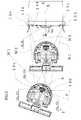
図1と図2は、本発明に係る清掃ロボット(移動ロボットの一例)1および充電ステーション8の要部の構成を示す。走行部2は2個のバッテリ3を内蔵し、左右の独立駆動車輪(走行車輪)4と前後の自在キャスタ5で直進走行、カーブ走行、その場での回転を行うことができる。overall structure:
FIG. 1 and FIG. 2 show the configuration of the main parts of a cleaning robot (an example of a mobile robot) 1 and a charging
走行部2の後ろ側には、床面のゴミを回転ブラシで掃きながら吸い込むための集塵作業部(スライド部)6を脱着可能に配設している。走行部2の上側には、集塵作業部6で床面のゴミを吸い上げるためのバキューム装置を内蔵してゴミを溜めるための集塵タンク部7が脱着可能に配設されている。前記集塵作業部6には、清掃ロボット1の充電を行うための第1接続端子部13が設けられている。
一方、充電ステーション8は、床面もしくは壁面等に予め設置されていると共に、前記清掃ロボット1の充電を行うための第2接続端子部14が設けられた充電ユニット14aを備えている。A dust collection work part (slide part) 6 for sucking the dust on the floor surface while sweeping it with a rotating brush is detachably disposed behind the traveling
On the other hand, the charging
清掃ロボット1:
図5に示すように、清掃ロボット1には左右の走行車輪4を走行用タイミングベルト45を介して回転駆動させる一対の駆動モータMrが設けられている。Cleaning robot 1:
As shown in FIG. 5, the cleaning
清掃ロボット1の後方には、前記集塵作業部6を清掃ロボット1の走行方向Yに直交する横方向Wにスライド移動可能に支持するスライド支持手段52が設けられている。スライド支持手段52は、清掃ロボット1の走行部2に設けたスライドガイド50と、該スライドガイド50に沿って集塵作業部6を横方向Wに移動可能に支持するスライド板51により構成されている。
前記集塵作業部6は、スライド板51が、スライド用タイミングベルト55を介してスライド駆動モータMsにより、前記横方向Wにスライド移動されることにより、該横方向Wにスライド移動される。したがって、スライド用タイミングベルト55およびスライド駆動モータMsは、集塵作業部6および該集塵作業部6に設けられた第1接続端子部13を横方向Wにスライド移動させるスライド移動手段56を構成している。Behind the
The dust
清掃ロボット1の機器構成:
図6に示すように、清掃ロボット1の走行部2には、前記駆動モータMrの制御を行うための走行制御手段61が設けられている。走行制御手段61により、清掃ロボット1の走行が制御され、種々の走行パターンで清掃ロボット1が走行されると共に、後述するように、集塵作業部6の第2接続端子部14に清掃ロボット1の第1接続端子部13が対面した状態になるように、清掃ロボット1の走行が制御される。Equipment configuration of cleaning robot 1:
As shown in FIG. 6, the traveling
前記集塵作業部6の周囲にはバンパ15が設けられている。前記集塵作業部6には、前記バンパ15が、障害物や充電ステーション8などに接触したか否かを検出するためのバンパセンサ63が、集塵作業部6の横方向Wの左右にそれぞれ設けられている。
前記バンパセンサ63は、清掃ロボット1が充電ステーション8を介してバッテリ3の充電を行う際には、第1接続端子部13と第2接続端子部14との横方向Wのズレを検出するズレ検出手段を構成している。A
When the cleaning
前記走行部2には、スライド駆動モータMsを制御するためのスライド制御手段62が設けられており、該スライド制御手段62は、バンパセンサ63が検出したズレに基づき、前記スライド移動手段56(図5)を駆動して2つの接続端子部13,14のズレを修正する。 The traveling
清掃ロボット1の充電のための帰還動作:
図2に示す清掃ロボット1を充電ステーション8に帰還させるために、走行部2にはリモート信号発信機9と2個の超音波受信機10(図1)を備えるとともに、充電ステーションには複数のリモート信号受信機11と2個の超音波発信機12を備えている。これにより、清掃ロボット1のリモート信号発信機9が信号を発信し、リモート信号受信機11がその信号を受信すると、2個の超音波発信機12は混信しないように所定時間タイミングをずらして発信させる。
それらの超音波を清掃ロボット1の2個の超音波受信機10が受信することにより、清掃ロボット1と充電ステーション8との距離と角度を算出して認識する。これを何度か繰り返しながら、清掃ロボット1は充電ステーション8前方の所定の位置まで帰還して停止する。Return action for charging cleaning robot 1:
In order to return the
When the two
集塵作業部6の後面には、6個の端子18(図8)を備えた第1接続端子部13が配設され、それらと対面して接続するために、充電ステーション8の前面には同じく6個の端子24(図10)を備えた第2接続端子部14が配設されている。
バッテリ3(図1)を充電するためには、正極、負極の端子に加えて、過充電にならないように充電完了のタイミングを図るための温度センサ端子が一般に必要とされている。この実施例では、2個のバッテリを備えており、バッテリの固体差にも対応できるようにそれぞれ独立的に充電できるようにするため、全6個の接続端子を設けている。A first
In order to charge the battery 3 (FIG. 1), in addition to the positive and negative terminals, a temperature sensor terminal is generally required for timing the completion of charging so as not to overcharge. In this embodiment, two batteries are provided, and a total of six connection terminals are provided so that each battery can be charged independently so as to be able to cope with individual differences of batteries.
図3は、清掃ロボット1と充電ステーション8との距離と角度を確認しながら帰還動作中と、充電ステーション8前面の所定位置に向けて帰還した状態を示している。
清掃ロボット1の周囲に複数配設したリモート信号発信機9から信号を発信し、充電ステーション8のリモート信号受信機11a 、11b、11cがその信号を受けると、充電ステーション8の距離R離れた2個の超音波発信機12a と12bは所定時間タイミングをずらして発信する。それらの超音波を清掃ロボット1の左右振り分けで離れて配置した2個の超音波受信機10a 、10b が受信し、超音波の到達時間から清掃ロボット1と充電ステーション8との距離M1、M2、N1、N2の距離を計測する。
なお、リモート信号受信機11a 、11b 、11c を3個設けているのは、受信の指向角度を広げるためである。FIG. 3 shows a state in which a return operation is being performed while confirming the distance and angle between the cleaning
When a signal is transmitted from a plurality of
The reason why three
充電ステーション8の中央をXY座標の原点(0,0)とし、清掃ロボット1の超音波受信機10a の座標を(X1 、Y1)とし、超音波受信機10bの座標を(X2、Y2)とすると、下記の関係式(1),(2) が成り立つ。
M12=(X1 +R/2)2+Y12 …(1)
M22=(X1 −R/2)2+Y12 …(2)The center of the charging
M12 = (X1 + R / 2)2 + Y12 (1)
M22 = (X1−R / 2)2 + Y12 (2)
この2式より、下記の(3),(4) 式に基づいて、超音波受信機10a の座標(X1 、Y1)を算出することができる。
X1=(M12−M22)/(2R) …(3)
Y1=[M12−{(M12−M22)/(2R)+(R/2)}2]1/2 …(4)
同様に、下記の(5),(6) 式に基づいて、超音波受信機10bの座標(X1 、Y1)も算出することができる
X2=(N12−N22)/(2R) …(5)
Y2=[N12−{(N12−N22)/(2R)+(R/2)}2]1/2 …(6)
そして、超音波受信機10aと10bの中央の座標(Xo,Yo)と、充電ステーションに対する対面角度θも下記の(7) 〜(9) 式に基づいて算出できる。
Xo=(X1+X2)/2 …(7)
Yo=(Y1+Y2)/2 …(8)
θ=tan-1{(Y2−Y1)/(X1 −X2 )} …(9)From these two equations, the coordinates (X1, Y1) of the ultrasonic receiver 10a can be calculated based on the following equations (3) and (4).
X1 = (M12 −M22 ) / (2R) (3)
Y1 = [M12 − {(M12 −M22 ) / (2R) + (R / 2)}2 ]1/2 (4)
Similarly, the coordinates (X1, Y1) of the ultrasonic receiver 10b can also be calculated based on the following equations (5), (6): X2 = (N12 −N22 ) / (2R) ( Five)
Y2 = [N12 − {(N12 −N22 ) / (2R) + (R / 2)}2 ]1/2 (6)
The central coordinates (Xo, Yo) of the ultrasonic receivers 10a and 10b and the facing angle θ with respect to the charging station can also be calculated based on the following equations (7) to (9).
Xo = (X1 + X2) / 2 (7)
Yo = (Y1 + Y2) / 2 (8)
θ = tan−1 {(Y2−Y1) / (X1−X2)} (9)
このように、充電ステーション8に対する清掃ロボット1の位置と角度を認識することができる。これを何度か繰り返し、図3の右側に示したように、充電ステーション8前面の所定位置に向かうように清掃ロボット1を走行させて帰還し、その場で停止させることができる。 Thus, the position and angle of the cleaning
図4Aは、清掃ロボット1が充電ステーション8前面の所定位置に停止した後、その場で180°回転し、バック走行しているところを示している。ただし、この時、清掃ロボット1が、充電ステーション8への帰還走行中に超音波の測定誤差や走行制御誤差などで位置ズレをしたり、その場の180°回転で位置ズレΔXを発生させた場合を示している。そして、清掃ロボット1は、その状態のまま矢印方向に集塵作業部6を前側にして、バック走行を開始する。 FIG. 4A shows a state where the cleaning
図4Bは、図4Aの状態から清掃ロボット1がバック走行を行った時に、集塵作業部6に配設したバンパ15が充電ステーション8の両側に設けた2個のガイド16a、16bの内のガイド16aに接触したところを示している。 FIG. 4B shows that the
バンパ15に障害物に当たると、集塵作業部6に対してバンパ15は、清掃ロボット1のバック走行の方向Y1に直交する前記横方向Wにスライド移動することができ、集塵作業部6には、前述したように、それがどの方向から当たったのかを検知できるようなバンパセンサ63(図6)が内蔵されている。 When the
前記バンパセンサ63(図6)により、バンパ15がガイド16aに接触したことを検知して、集塵作業部6はバンパ15がガイド16aから離れる横方向W(矢印の方向)にスライド動作を行いながらバック走行を続ける。即ち、ガイド16aと16bの間隔は、集塵作業部6と略同じか又は若干広く設定されているため、ガイド16aと16bの間に、集塵作業部6が納まるようにバック走行する。 The bumper sensor 63 (FIG. 6) detects that the
図4Cは、充電ステーション8の前面に設けられた4個のストッパピン17a、17b、17c、17dに集塵作業部6のバンパ15が前記ストッパピン17a、17b、17c、17dのそれぞれに接触したところを示している。この時、前記バンパセンサ63(図6)がストッパピン17a、17b、17c、17dに接触したことを検知するため、清掃ロボット1のバック走行が停止する。 FIG. 4C shows that the
ところで、もしも、位置ズレΔX(図4A)だけでなく、充電ステーションに対して対面角度θもズレていた場合には、4個のストッパピン17a、17b、17c、17dの内の外側のストッパピン17a又は17dが先に接触する。そこで、接触していない側に近接するように走行部2をゆっくりと回転動作させ、接触していなかった側のストッパピン17a又は17dもバンパ15に接触したところで回転動作を停止すれば良い。以上で清掃ロボット1の集塵部6は充電ステーション8に対して、所定の位置に正確に帰還した状態になる。 By the way, if not only the positional deviation ΔX (FIG. 4A) but also the facing angle θ with respect to the charging station, the outer stopper pin among the four
図6に示す4個のストッパピン17a、17b、17c、17dの内のストッパピン17bと17cの内の先端には、接触検知センサ64が設けられている。このストッパピン17bと17cがバンパ15と接触した時には、接触検知センサ64が充電ステーション8に清掃ロボット1が帰還したことを検知し、集塵作業部6の第1接続端子部13と充電ステーション8の第2接続端子部14の連結動作に移行する。
したがって、接触検知センサ64は、前記2つの端子部13,14が互いに平行となった状態で対面しているか否かを検出する傾き検出手段を構成している。前記走行制御手段61は、前記接触検知センサ64で検出された傾きに基づいて清掃ロボット1を回転させて前記2つの端子部13,14が互いに平行となるように清掃ロボット1の姿勢を制御する。A contact detection sensor 64 is provided at the tip of the stopper pins 17b and 17c among the four
Therefore, the contact detection sensor 64 constitutes an inclination detection means for detecting whether or not the two
なお、4個のストッパピン17a、17b、17c、17dは、2個のストッパピン17aと17d のみとし、そのそれぞれの先端に接触検知センサ64を設けて、両端の2個のストッパピン17a,17dの両者の接触検知センサ64が検知した時に、集塵作業部6の第1接続端子部13と充電ステーション8の第2接続端子部14の連結動作に移行させても良い。 The four
更に又、不図示の接触検知センサを内蔵したストッパピン17bと17cを廃止し、バンパ15で横方向Wの両端のストッパピン17a,17dを検知して、清掃ロボット1の集塵部6が充電ステーション8に対して、所定の位置に正確に帰還して停止制御するとともに、清掃ロボット1側のリモート信号発信機9で帰還完了信号を発信させ、充電ステーション8のリモート信号受信機11でその信号を受信し、集塵作業部6の第1接続端子部13と充電ステーション8の第2接続端子部14の連結動作に移行させても良い。 Furthermore, the stopper pins 17b and 17c having built-in contact detection sensors (not shown) are eliminated, and the
第1接続端子部13:
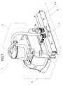
図7は、清掃ロボット1を斜め後から見たところで、集塵作業部6の一部の集塵ケース6aを透かして描き、集塵作業部6の後面には6個配列した第1接続端子部13の構成を示している。図8は、図7の第1接続端子部13とその近傍を拡大して示している。First connection terminal portion 13:
FIG. 7 is a perspective view of the cleaning
図8に示すように、集塵ケース6a には、第1接続端子部13の端子18に対応して6個のケース穴6bが形成されている。第1接続端子部13には、ケース穴6bを内側から塞ぐように外部に一部を露出させた露出接続端子18が、集塵ケース6a に固定された台板19とは電気的に絶縁されて固設されている台板20に対して回転軸21で回転可能に取り付けられている。
回転軸21の内側には不図示のバネが配されて、露出接続端子18がケース穴6bを塞ぐように付勢されている。露出接続端子18の内面側には、間隙を設けて対面するように切片22を配設しており、切片22は、図5に示す走行部2に配設されたバッテリ3に電気的に接続されている。As shown in FIG. 8, six
A spring (not shown) is disposed on the inner side of the rotating shaft 21, and the exposed
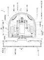
図9は、図2の充電ステーション8を斜め後から示しており、ケース8aの内部が分かるように透かして示している。図5の清掃ロボット1の2個のバッテリ3(図5)に対応して、図6の充電ステーション8には、2個の充電器23、リモート信号受信機11a、11b 、11c、超音波発信機12a、12b 、ガイド16a、16bが配設されている。更に、図8の集塵作業部6の第1接続端子部13の6個の端子18に対応する位置には、図10に示す6個の端子24が第2接続端子部14に配置されている。 FIG. 9 shows the charging
充電ユニット14a:
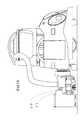
図10は、図9に示した充電ユニット14aとその近傍を拡大して示している。図10に示すように、第2接続端子部14は、軸方向Yに摺動可能な6個の接続端子軸からなる端子24と、その端部にそれぞれ固定された6個の円板25と、円板25に間隙を設けて対面し、接触可能な6個の二股の切片26とで構成されている。Charging
FIG. 10 is an enlarged view of the charging
6個の接続端子軸24の内、隣り合う3個の接続端子軸24を1つのユニット単位にして、2つのユニットを構成している。そして、それぞれ3個づつの接続端子軸24はお互いに電気的に絶縁した構成で、台板27aと台板28a及び台板27bと図面上で影部のため不図示の台板28bで上下に挟み込んで連結している。
したがって、台板27a,27b,28a,28bは第2接続端子部14の端子24を横方向Wに直交する方向Yに突出進退可能に支持する端子支持手段を構成している。Of the six
Accordingly, the
上側の台板27a,27bの上部には、ケース8a(図9)との間にそれぞれバネ29が掛けられて、6個の接続端子軸24を充電ステーション8の外方に向って押し出す方向Y1に付勢している。図10は、バネ29で引っ張られている台板27a,27bは、摺動規制板30でバネ29に抗して付勢された状態を示している。 The
摺動規制板30は、傾き防止板31a、31bに支えられて軸32の軸方向Yに摺動可能に軸32に嵌合し、クランク33に対して軸34で回転可能に連結している。クランク33は、モータ35と結合している円板36に対して偏芯した位置の軸37と回転可能に連結している。円板36の回転中心からの距離がそれぞれ異なる位置に、2個の穴36a 、36bの開口穴があり、穴36aの真下には穴を検知するための反射型のフォトセンサ38aが固設されている。 The sliding
図10の待機状態から、モータ35が回転して円板36が180°回転すると、穴36bが反射型のフォトセンサ38bの真上にくることで円板36が180°回転したことを検知できる。
この時、クランク33の動作に連動している摺動規制板30は、軸32に嵌合して前方に押し出される。そして、摺動規制板30に台板27a、27bが当接して摺動規制されていた2つの接続端子ユニットは、バネ29の付勢力で前に押し出される。これにより、充電ステーション8の前面から6個の接続端子軸24が突出した充填状態になるとともに、その反対側の端部の6個の円板25は、6個の切片26にそれぞれ接触する。
したがって、クランク33、モータ35および円板36は、前記端子支持手段により突出可能に支持された各端子18を前記突出退避方向Yに、それぞれ進退させる進退駆動手段を構成している。When the
At this time, the sliding restricting
Therefore, the crank 33, the
ここで、円板36の孔36a,36bの位置をフォトセンサ38a,38bが検出することにより、現在の状態が、第2接続端子部14の突出状態であるか否かが判別される。図6に示す接続制御手段65は、充電を行わない待機状態の場合には、図10に示すフォトセンサ38aが前記円板36の孔36aを検出する位置になるように進退駆動手段を動作させる。
一方、清掃ロボット1と充電ステーション8の両端子部13,14が互いに対面し、かつ、本質的にズレがない状態または修正された状態になった場合には、接続制御手段65が、前記進退駆動手段を動作させて、フォトセンサ38bが円板36の孔36bを検出する位置になるように前記充填状態に移動させることにより、前記端子24を突出させて前記両端子18,24を互いに接続させる。Here, when the photosensors 38a and 38b detect the positions of the holes 36a and 36b of the
On the other hand, when the
この時、切片26は充電器23(図9)に常に電気的に接続されているため、切片26を介して接続端子軸24が充電器23と電気的に接続された状態になる。
この時は図4Cのように、充電ステーション8に清掃ロボット1が帰還して、充電できる体勢になっているおり、充電器23(図9)に電気的に接続される図10の接続端子軸24が突出動作すると、接続端子軸24は、図8の集塵ケース6 aのケース穴6bを通して露出接続端子18を回転軸21を回転中心にして押し込むとともに、露出接続端子18の後面が切片22に押し付けられる。
これにより、図9の充電器23と、図6のバッテリ3が電気的に接続されて、充電が開始される。At this time, since the
At this time, as shown in FIG. 4C, the cleaning
Thereby, the
したがって、床面を自律的に移動する清掃ロボット1の測距センサの精度誤差や走行制御の精度誤差があって、清掃ロボット1が充電のために充電ステーションに帰還した時に、位置ズレや角度ズレがあっても、清掃ロボット1と充電ステーションの接続端子18,24が精度良く結合することが可能になる。 Therefore, when there is an accuracy error of the distance measuring sensor of the cleaning
充電の完了は、図8および図10の6個の接続端子18,24の内の2個が、2個のバッテリ3(図6)のそれぞれの充電完了のタイミングを知らせるための端子であるので、それに基づいて図9の充電器23が判断して充電を完了させる。
その充電完了とともに、再度、図10のモータ35を回転させ、円板36を180°回転したところで、円板36の穴36aをフォトセンサ38aが検知してモータ35の回転を停止し、図10の待機状態に戻って、清掃ロボット1が集塵作業を行うためにいつでも出動できるような待機状態となる。As for the completion of charging, two of the six
When the charging is completed, the
なお、もしも、充電完了前に、図6の充電ステーション8から清掃ロボット1 が出動しなければならない場合には、図1の清掃ロボット1のリモート信号発信機9から出動する旨の信号を、図2の充電ステーション8のリモート信号受信機11に送り、その信号で図10の待機状態に戻してから清掃ロボット1を出動させるようにすればよい。 If the
この充電完了前に出動させる信号伝達を、図2のリモート信号発信機9とリモート信号受信機11で行わせたが、第1接続端子部13と第2接続端子14の接続端子を増設し、その接続端子で出動信号を伝達してもよい。 The signal transmission to be dispatched before the completion of charging is performed by the
このように充電時以外の時は、図8の集塵作業部6の露出接続端子18とバッテリ3は電気的に遮断されているとともに、図9の充電ステーション8の充電接続端子軸24(図10)と充電器23も電気的に遮断されている。そのため、不用意に露出接続端子18(図8)や、充電接続端子軸24(図10)に手で触れても感電することはなく、ホコリなどが付着して漏電の発生も防止できる。 As described above, when the battery is not charged, the exposed
ここで、以上に述べた実施例では、図10の充電ステーション8の6個の第2接続端子14は、1 個のモータ35で同じタイミングで、図2の集塵作業部6の第1接続端子部13に接続するため、清掃ロボット1 に搭載された2個のバッテリ3(図1)が、ほぼ同じような状態で使用されていればよいが、新しいバッテリと古いバッテリが組み込まれることが想定される場合には、それぞれのバッテリに対応するように、図10の充電ユニット14aに2個のモータ35を搭載して、3個づつの接続端子24が独立して接続動作を行わせるようにすれば、それぞれのバッテリ充電時間のタイムラグにも対応可能である。 Here, in the embodiment described above, the six
図11および図12は、実施例2を示す。
集塵作業部8には、清掃ロボット1の走行部2に対して集塵作業部6を上下に昇降するための昇降部39を備えている。この昇降部39は、集塵作業を行う時には集塵作業部を降下させ、集塵作業を行わずに移動したり、作業停止している時には上昇させるのが本来の機能である。この実施例は、この昇降機能を接続端子の接続動作にも活用した例である。11 and 12 show a second embodiment.
The dust
清掃ロボット1が充電ステーション8に帰還してきた時には、図11のように集塵作業部8を上に昇降部39で持ち上げた状態である。この時は、集塵作業部6の接続端子40と充電ステーション8の接続端子41は、上下方向で離間した状態である。
バンパセンサ63(図6)により、集塵作業部6のバンパ15が充電ステーション8のストッパピン17に接触したことを検知すると、清掃ロボット1の充電ステーション8への帰還走行動作を停止するとともに、昇降部39を動作させて集塵作業部6を降下の動作を開始する。図12のように、接続端子40と接続端子41が接続するところまで降下すると、降下動作を停止して充電を開始する。充電が完了すると、再び上昇動作を行って出動待機状態となる。When the cleaning
When it is detected by the bumper sensor 63 (FIG. 6) that the
この図11と図12の実施例の場合、充電ステーション8の側の接続端子41は、図7と図8のような構造にし、集塵作業部6の側の接続端子40は、昇降動作に連動してバッテリと電気的に接続させる構造にすれば、上記のような感電や漏電も防止可能である。
なお、図11および図12は集塵作業部6の降下動作で接続させたが、逆に集塵作業部6の上昇動作で接続するようにしてもよい。
その他の構成は、実施例1と同様であり、同一部分または相当部分に同一符号を付して、その説明を省略する。11 and 12, the connection terminal 41 on the charging
11 and 12 are connected by the lowering operation of the dust
Other configurations are the same as those of the first embodiment, and the same reference numerals are given to the same portions or corresponding portions, and the description thereof is omitted.
なお、前述の各実施例では、第2接続端子部14の端子24を突出退避方向Yに進退させることとしたが、第2接続端子部14の端子24を突出退避させる代わりに、第1接続端子部13の端子18を突出退避させるようにしてもよい。
また、充電法式としては、バッテリの自然放電を補うために、負荷から切り離して絶えず微小電流を流しておくトリクル充電方式を採用してもよい。In each of the above-described embodiments, the
In addition, as a charging method, a trickle charging method in which a minute current is continuously supplied after being disconnected from the load may be employed in order to compensate for the spontaneous discharge of the battery.
更に、以上述べた各実施例では、移動ロボットの一例として清掃ロボットを例示して記載したが、清掃ロボットのみに限定するものではなく、床面を自律的に移動するロボットであれば本発明を適用することができる。移動ロボットとしては、たとえば、全方向に移動可能な走行部を備えていてもよい。 Further, in each of the embodiments described above, the cleaning robot is exemplified and described as an example of the mobile robot. However, the present invention is not limited to the cleaning robot, and the present invention is not limited to the robot that moves autonomously on the floor surface. Can be applied. As a mobile robot, you may provide the traveling part which can move to all directions, for example.
変形例:
なお、前述の各実施例では、横方向Wにスライド可能な集塵作業部6に第1接続端子部13を設けた清掃ロボット1について説明したが、必ずしも第1接続端子部13を横方向Wにスライドさせる機構を設ける必要はない。
以下に説明する各変形例では、第1接続端子部13を横方向Wにスライド移動することなく、第1接続端子部13と第2接続端子部14の端子18,24同士を接合させる充電ユニット14aの構成について説明する。Variations:
In each of the above-described embodiments, the cleaning
In each modification described below, a charging unit that joins the
変形例1;
図13Aに示すように、充電ユニット14aは、横方向Wに沿って設けられたレール70に沿って移動可能に設定されている。充電ユニット14aには、該充電ユニット14aを横方向Wに移動させるための移動モータMおよび駆動輪71からなる駆動装置が設けられている。
As shown in FIG. 13A, the charging
清掃ロボット1の第1接続端子部13と第2接続端子14との間にズレが生じた場合には、清掃ロボット1の第1接続端子部13を横方向W方向に移動させることなく、当該ズレに応じて、図13Bに示すように、充電ユニット14aを横方向Wに移動すると共に、第2接続端子部14の端子24を突出させることにより、清掃ロボット1に設けられた第1接続端子部13の端子18と、第2接続端子14の端子24とを互いに接続させることができる。
したがって、第1接続端子部13を清掃ロボット1本体に設けることも可能であると共に、集塵作業部6等の横方向Wに移動する部分を有しない種々の移動ロボットにおいてもスムースな充電が可能となる。When a deviation occurs between the first
Therefore, the first
変形例2;
図13Cに示すように、充電ユニット14aは、床面や壁面等に固定されている。
図1の清掃ロボット1は、集塵作業部6をスライド移動させることなく、走行部2のみを駆動することにより、該清掃ロボット1に設けた第1接続端子部13と第2接続端子14との位置合わせを行った後、第2接続端子部14の端子24が突出し、両端子18,24が互いに接合される。
As illustrated in FIG. 13C, the charging
The cleaning
変形例3;
図13Dに示すように、充電ユニット14aは、横方向Wに沿って設けられたレール70に沿って横方向Wに移動可能に設定されている。充電ユニット14aには、該充電ユニット14aを横方向Wに移動させるための駆動装置が設けられている。一方、第2接続端子14に設けた端子24は、突出した状態で固定して設けられている。
As shown in FIG. 13D, the charging
本発明は、特に、移動ロボットの充電システムおよび充電ユニットに適用することができる。 The present invention is particularly applicable to mobile robot charging systems and charging units.
1:清掃ロボット(移動ロボット)
2:走行部
3:バッテリ
4:走行車輪
6:集塵作業部(スライド部)
13:第1接続端子部
14:第2接続端子部
14a:充電ユニット
18,24:端子
27a,27b,28a,28b:台板(端子支持手段)
33:クランク(進退駆動手段)
35:モータ(進退駆動手段)
36:円板(進退駆動手段)
52:スライド支持手段
56:スライド移動手段
61:走行制御手段
62:スライド制御手段
63:バンパセンサ(ズレ検出手段)
64:接触検知センサ(傾き検出手段)
65:接続制御手段
W:横方向1: Cleaning robot (mobile robot)
2: traveling unit 3: battery 4: traveling wheel 6: dust collection working unit (sliding unit)
13: 1st connection terminal part 14: 2nd
33: Crank (advance / retreat driving means)
35: Motor (advance / retreat driving means)
36: Disc (advance / retreat drive)
52: Slide support means 56: Slide movement means 61: Travel control means 62: Slide control means 63: Bumper sensor (deviation detection means)
64: Contact detection sensor (tilt detection means)
65: Connection control means W: Lateral direction
Claims (11)
Translated fromJapanese前記ロボットに設けられ複数の端子を有する第1接続端子部と、
前記充電ユニットに設けられ、前記各端子に接続される複数の端子を有する第2接続端子部と、
前記充電ユニットの第2接続端子部に前記ロボットの前記第1接続端子部が対面した状態となるように、前記ロボットの走行を制御する走行制御手段と、
前記第1または第2接続端子部の一方をロボットの走行方向に直交する横方向にスライド移動可能に支持するスライド支持手段と、
前記スライド支持手段によりスライド移動可能に支持された接続端子部を前記横方向にスライド移動させるスライド駆動手段と、
前記第1接続端子部と第2接続端子部との前記横方向のズレを検出するズレ検出手段と、
前記検出されたズレに基づいて前記スライド駆動手段を駆動して前記2つの端子部のズレを修正するスライド制御手段と、
前記第1または第2接続端子部の端子を前記横方向に直交する方向に突出退避可能に支持する端子支持手段と、
前記端子支持手段により突出可能に支持された端子を前記突出退避方向に進退させる進退駆動手段と、
前記両端子部が互いに対面し、かつ、本質的に前記ズレがない状態または修正された状態で、前記進退駆動手段により前記端子を突出させて前記両端子を互いに接続させる接続制御手段とを備えた充電システム。A charging system comprising: a mobile robot that travels on a floor surface by rotating a traveling wheel with electric power from a battery; and a charging unit installed on the floor surface or a wall surface, and the battery is charged via the charging unit. There,
A first connection terminal portion provided on the robot and having a plurality of terminals;
A second connection terminal portion provided in the charging unit and having a plurality of terminals connected to the terminals;
Travel control means for controlling the travel of the robot so that the second connection terminal portion of the charging unit faces the first connection terminal portion of the robot;
Slide support means for supporting one of the first or second connection terminal portions so as to be slidable in a lateral direction perpendicular to the traveling direction of the robot;
Slide drive means for slidingly moving the connection terminal portion supported by the slide support means so as to be slidable in the lateral direction;
A displacement detecting means for detecting the lateral displacement between the first connection terminal portion and the second connection terminal portion;
Slide control means for driving the slide drive means based on the detected deviation to correct the deviation between the two terminal portions;
Terminal support means for supporting the terminal of the first or second connection terminal portion so as to protrude and retract in a direction orthogonal to the lateral direction;
Advancing and retracting drive means for advancing and retracting the terminal supported by the terminal supporting means so as to be able to protrude;
Connection control means for projecting the terminals by the advance / retreat driving means to connect the terminals to each other in a state where the both terminal portions face each other and are essentially free from or displaced. Charging system.
前記スライド支持手段が前記ロボットに設けられ、前記ロボットの走行部に対し前記スライド支持手段を介してスライド移動可能なスライド部に前記第1接続端子部が設けられている充電システム。In claim 1,
A charging system in which the slide support means is provided in the robot, and the first connection terminal part is provided in a slide part that is slidable with respect to a traveling part of the robot via the slide support means.
前記スライド部には、所定の作業を行う作業部が設けられている充電システム。In claim 2,
A charging system in which the slide unit is provided with a working unit for performing a predetermined work.
前記端子支持手段が前記充電ユニットに設けられている充電システム。In claim 1, 2 or 3,
A charging system in which the terminal support means is provided in the charging unit.
前記2つの端子部が互いに平行となった状態で対面しているか否かを検出する傾き検出手段を更に備え、
前記走行制御手段は、前記傾き検出手段で検出された傾きに基づいて前記ロボットを回転させて前記2つの端子部が互いに平行となるように前記ロボットの姿勢を制御することを特徴とする充電システム。In claim 1,
Further comprising an inclination detecting means for detecting whether or not the two terminal portions face each other in a parallel state;
The traveling control means controls the posture of the robot so that the two terminal portions are parallel to each other by rotating the robot based on the inclination detected by the inclination detecting means. .
前記ロボットに設けられ複数の端子を有する第1接続端子部と、
前記充電ユニットに設けられ、前記各端子に接続される複数の端子を有する第2接続端子部と、
前記充電ユニットの第2接続端子部に前記ロボットの前記第1接続端子部が対面した状態となるように、前記ロボットの走行を制御する走行制御手段と、
前記第1または第2接続端子部の端子を前記横方向に直交する方向に突出退避可能に支持する端子支持手段と、
前記端子支持手段により突出可能に支持された端子を前記突出退避方向に進退させる進退駆動手段と、
前記両端子部が互いに対面した状態状態で、前記進退駆動手段により前記端子を突出させて前記両端子を互いに接続させる接続制御手段とを備えた充電システム。A charging system comprising: a mobile robot that travels on a floor surface by rotating a traveling wheel with electric power from a battery; and a charging unit installed on the floor surface or a wall surface, and the battery is charged via the charging unit. There,
A first connection terminal portion provided on the robot and having a plurality of terminals;
A second connection terminal portion provided in the charging unit and having a plurality of terminals connected to the terminals;
Travel control means for controlling the travel of the robot so that the second connection terminal portion of the charging unit faces the first connection terminal portion of the robot;
Terminal support means for supporting the terminal of the first or second connection terminal portion so as to protrude and retract in a direction orthogonal to the lateral direction;
Advancing and retracting drive means for advancing and retracting the terminal supported by the terminal supporting means so as to be able to protrude;
A charging system comprising: connection control means for projecting the terminals by the advance / retreat driving means to connect the terminals to each other in a state where the both terminal portions face each other.
前記ロボットに設けられ複数の端子を有する第1接続端子部と、
前記充電ユニットに設けられ、前記各端子に接続される複数の端子を有する第2接続端子部と、
前記充電ユニットの第2接続端子部に前記ロボットの前記第1接続端子部が対面した状態となるように、前記ロボットの走行を制御する走行制御手段と、
前記第1または第2接続端子部の一方をロボットの走行方向に直交する横方向にスライド移動可能に支持するスライド支持手段と、
前記スライド支持手段によりスライド移動可能に支持された接続端子部を前記横方向にスライド移動させるスライド駆動手段と、
前記第1接続端子部と第2接続端子部との前記横方向のズレを検出するズレ検出手段と、
前記検出されたズレに基づいて前記スライド駆動手段を駆動して前記2つの端子部のズレを修正するスライド制御手段と、
前記両端子部が互いに対面し、かつ、本質的に前記ズレがない状態または修正された状態で、前記一方の端子を他方の端子に向って前進させて前記両端子を互いに接続させる接続制御手段とを備えた充電システム。A charging system comprising: a mobile robot that travels on a floor surface by rotating a traveling wheel with electric power from a battery; and a charging unit installed on the floor surface or a wall surface, and the battery is charged via the charging unit. There,
A first connection terminal portion provided on the robot and having a plurality of terminals;
A second connection terminal portion provided in the charging unit and having a plurality of terminals connected to the terminals;
Travel control means for controlling the travel of the robot so that the second connection terminal portion of the charging unit faces the first connection terminal portion of the robot;
Slide support means for supporting one of the first or second connection terminal portions so as to be slidable in a lateral direction perpendicular to the traveling direction of the robot;
Slide drive means for slidingly moving the connection terminal portion supported by the slide support means so as to be slidable in the lateral direction;
A displacement detecting means for detecting the lateral displacement between the first connection terminal portion and the second connection terminal portion;
Slide control means for driving the slide drive means based on the detected deviation to correct the deviation between the two terminal portions;
Connection control means for connecting the two terminals to each other by advancing the one terminal toward the other terminal in a state where the both terminal portions face each other and are essentially free from or displaced. And a charging system.
前記ロボットに設けられた第1接続端子部の複数の各端子に接続される複数の端子を有する第2接続端子部と、
前記第2接続端子部をロボットの走行方向に直交する横方向にスライド移動可能に支持するスライド支持手段と、
前記第2接続端子部を前記横方向にスライド移動させるスライド駆動手段と、
前記第1接続端子部と第2接続端子部との前記横方向のズレを検出するズレ検出手段と、
前記検出されたズレに基づいて前記スライド駆動手段を駆動して前記2つの端子部のズレを修正するスライド制御手段と、
前記第2接続端子部の端子を前記横方向に直交する方向に突出退避可能に支持する端子支持手段と、
前記端子支持手段により突出可能に支持された端子を前記突出退避方向に進退させる進退駆動手段と、
前記両端子部が互いに対面し、かつ、本質的に前記ズレがない状態または修正された状態で、前記進退駆動手段により前記第2接続端子部の端子を突出させて前記両端子を互いに接続させる接続制御手段とを備えた充電ユニット。A charging unit that charges the battery via a charging unit installed on a floor surface or a wall surface to a mobile robot that travels on the floor surface by rotating traveling wheels with electric power from the battery,
A second connection terminal part having a plurality of terminals connected to a plurality of terminals of the first connection terminal part provided in the robot;
Slide support means for slidably supporting the second connection terminal portion in a lateral direction orthogonal to the traveling direction of the robot;
Slide driving means for slidingly moving the second connection terminal portion in the lateral direction;
A displacement detecting means for detecting the lateral displacement between the first connection terminal portion and the second connection terminal portion;
Slide control means for driving the slide drive means based on the detected deviation to correct the deviation between the two terminal portions;
Terminal support means for supporting the terminal of the second connection terminal portion so as to be able to protrude and retract in a direction orthogonal to the lateral direction;
Advancing and retracting drive means for advancing and retracting the terminal supported by the terminal supporting means so as to be able to protrude;
In a state where the both terminal portions face each other and there is essentially no deviation or a corrected state, the terminals of the second connection terminal portion are projected by the advance / retreat driving means to connect the two terminals to each other. A charging unit comprising connection control means.
前記ロボットに設けられた第1接続端子部の複数の各端子に接続される複数の端子を有する第2接続端子部と、
前記第2接続端子部の端子を前記横方向に直交する方向に突出退避可能に支持する端子支持手段と、
前記端子支持手段により突出可能に支持された端子を前記突出退避方向に進退させる進退駆動手段と、
前記両端子部が互いに対面し、かつ、本質的に前記ズレがない状態または修正された状態で、前記進退駆動手段により前記第2接続端子部の端子を突出させて前記両端子を互いに接続させる接続制御手段とを備えた充電ユニット。A charging unit that charges the battery via a charging unit installed on a floor surface or a wall surface to a mobile robot that travels on the floor surface by rotating traveling wheels with electric power from the battery,
A second connection terminal part having a plurality of terminals connected to a plurality of terminals of the first connection terminal part provided in the robot;
Terminal support means for supporting the terminal of the second connection terminal portion so as to be able to protrude and retract in a direction orthogonal to the lateral direction;
Advancing and retracting drive means for advancing and retracting the terminal supported by the terminal supporting means so as to be able to protrude;
In a state where the both terminal portions face each other and there is essentially no deviation or a corrected state, the terminals of the second connection terminal portion are projected by the advance / retreat driving means to connect the two terminals to each other. A charging unit comprising connection control means.
前記ロボットに設けられた第1接続端子部の複数の各端子に接続される複数の端子を有する第2接続端子部と、
前記第2接続端子部をロボットの走行方向に直交する横方向にスライド移動可能に支持するスライド支持手段と、
前記第2接続端子部を前記横方向にスライド移動させるスライド駆動手段と、
前記第1接続端子部と第2接続端子部との前記横方向のズレを検出するズレ検出手段と、
前記検出されたズレに基づいて前記スライド駆動手段を駆動して前記2つの端子部のズレを修正するスライド制御手段と、
前記両端子部が互いに対面し、かつ、本質的に前記ズレがない状態または修正された状態で、前記一方の端子を他方の端子に向って前進させて前記両端子を互いに接続させる接続制御手段とを備えた充電ユニット。A charging unit that charges the battery via a charging unit installed on a floor surface or a wall surface to a mobile robot that travels on the floor surface by rotating traveling wheels with electric power from the battery,
A second connection terminal part having a plurality of terminals connected to a plurality of terminals of the first connection terminal part provided in the robot;
Slide support means for slidably supporting the second connection terminal portion in a lateral direction orthogonal to the traveling direction of the robot;
Slide driving means for slidingly moving the second connection terminal portion in the lateral direction;
A displacement detecting means for detecting the lateral displacement between the first connection terminal portion and the second connection terminal portion;
Slide control means for driving the slide drive means based on the detected deviation to correct the deviation between the two terminal portions;
Connection control means for connecting the two terminals to each other by advancing the one terminal toward the other terminal in a state where the both terminal portions face each other and are essentially free from or displaced. And a charging unit.
前記移動ロボットは、バッテリを搭載し、走行車輪を有する走行部と走行部に対してスライド駆動モータで横方向にスライド移動可能なスライド部とを備え、
前記スライド部は、該スライド部のスライド方向から近接する物体を検知するための一対の側面物体検知センサと、前記スライド方向に垂直な方向から近接する物体を検知するための後面物体検知センサと、前記バッテリを充電するための複数の第一接続端子とを備え、
前記充電ユニットには、前記充電ユニットの前面から前方に突出し、前記スライド部の幅と同等または若干広い幅で、前記スライド部を挟み込む形状一対のガイド部と、前記第一接続端子に対応した位置に設けられた複数の第二接続端子とを備え、
前記移動ロボットの前記スライド部が前記充電ユニットに対面した状態で走行している際に、前記充電ユニットの前記ガイド部を一方の前記側面物体検知センサが検知した時には、当該一方の前記センサが前記ガイド部を検知しなくなる方向に前記スライド部をスライドさせ、
前記充電ユニットを前記後面物体検知センサが検知した時は、前記移動ロボットの走行動作と前記スライド部のスライド動作とを停止させて、前記第一接続端子を前記第二接続端子に電気的に接続させる接続制御手段を設けたことを特徴とする移動ロボットの自動充電システム。A mobile robot capable of running on the floor with a battery, and a charging unit installed on the floor for charging the battery of the mobile robot,
The mobile robot is equipped with a traveling unit having a battery and having traveling wheels, and a slide unit that can slide and move laterally with a slide drive motor with respect to the traveling unit.
The slide part includes a pair of side object detection sensors for detecting an object approaching from the slide direction of the slide part, and a rear object detection sensor for detecting an object approaching from a direction perpendicular to the slide direction; A plurality of first connection terminals for charging the battery;
The charging unit protrudes forward from the front surface of the charging unit, and has a pair of guide portions sandwiching the slide portion with a width equal to or slightly wider than the slide portion, and a position corresponding to the first connection terminal A plurality of second connection terminals provided in the
When one of the side object detection sensors detects the guide portion of the charging unit while the slide portion of the mobile robot is running in a state of facing the charging unit, the one sensor is Slide the slide part in a direction that stops detecting the guide part,
When the rear object detection sensor detects the charging unit, the traveling operation of the mobile robot and the sliding operation of the slide portion are stopped, and the first connection terminal is electrically connected to the second connection terminal. An automatic charging system for a mobile robot, characterized in that a connection control means is provided.
Priority Applications (1)
| Application Number | Priority Date | Filing Date | Title |
|---|---|---|---|
| JP2007176965AJP2009015611A (en) | 2007-07-05 | 2007-07-05 | Charging system, charging unit, and system for automatically charging moving robot |
Applications Claiming Priority (1)
| Application Number | Priority Date | Filing Date | Title |
|---|---|---|---|
| JP2007176965AJP2009015611A (en) | 2007-07-05 | 2007-07-05 | Charging system, charging unit, and system for automatically charging moving robot |
Publications (1)
| Publication Number | Publication Date |
|---|---|
| JP2009015611Atrue JP2009015611A (en) | 2009-01-22 |
Family
ID=40356437
Family Applications (1)
| Application Number | Title | Priority Date | Filing Date |
|---|---|---|---|
| JP2007176965APendingJP2009015611A (en) | 2007-07-05 | 2007-07-05 | Charging system, charging unit, and system for automatically charging moving robot |
Country Status (1)
| Country | Link |
|---|---|
| JP (1) | JP2009015611A (en) |
Cited By (42)
| Publication number | Priority date | Publication date | Assignee | Title |
|---|---|---|---|---|
| CN101923352A (en)* | 2010-07-05 | 2010-12-22 | 东南大学 | Indoor security robot with automatic return to charging stand function and return method |
| CN102437601A (en)* | 2011-10-21 | 2012-05-02 | 中国科学院苏州纳米技术与纳米仿生研究所 | Cloud robot autonomous charging system and method |
| US8239992B2 (en) | 2007-05-09 | 2012-08-14 | Irobot Corporation | Compact autonomous coverage robot |
| US8253368B2 (en) | 2004-01-28 | 2012-08-28 | Irobot Corporation | Debris sensor for cleaning apparatus |
| US8368339B2 (en) | 2001-01-24 | 2013-02-05 | Irobot Corporation | Robot confinement |
| US8374721B2 (en) | 2005-12-02 | 2013-02-12 | Irobot Corporation | Robot system |
| US8380350B2 (en) | 2005-12-02 | 2013-02-19 | Irobot Corporation | Autonomous coverage robot navigation system |
| US8386081B2 (en) | 2002-09-13 | 2013-02-26 | Irobot Corporation | Navigational control system for a robotic device |
| US8382906B2 (en) | 2005-02-18 | 2013-02-26 | Irobot Corporation | Autonomous surface cleaning robot for wet cleaning |
| US8390251B2 (en) | 2004-01-21 | 2013-03-05 | Irobot Corporation | Autonomous robot auto-docking and energy management systems and methods |
| US8387193B2 (en) | 2005-02-18 | 2013-03-05 | Irobot Corporation | Autonomous surface cleaning robot for wet and dry cleaning |
| US8396592B2 (en) | 2001-06-12 | 2013-03-12 | Irobot Corporation | Method and system for multi-mode coverage for an autonomous robot |
| US8412377B2 (en) | 2000-01-24 | 2013-04-02 | Irobot Corporation | Obstacle following sensor scheme for a mobile robot |
| US8417383B2 (en) | 2006-05-31 | 2013-04-09 | Irobot Corporation | Detecting robot stasis |
| US8418303B2 (en) | 2006-05-19 | 2013-04-16 | Irobot Corporation | Cleaning robot roller processing |
| US8428778B2 (en) | 2002-09-13 | 2013-04-23 | Irobot Corporation | Navigational control system for a robotic device |
| US8463438B2 (en) | 2001-06-12 | 2013-06-11 | Irobot Corporation | Method and system for multi-mode coverage for an autonomous robot |
| US8474090B2 (en) | 2002-01-03 | 2013-07-02 | Irobot Corporation | Autonomous floor-cleaning robot |
| US8515578B2 (en) | 2002-09-13 | 2013-08-20 | Irobot Corporation | Navigational control system for a robotic device |
| JP2013168151A (en)* | 2012-02-16 | 2013-08-29 | Micro-Star Internatl Co Ltd | Cleaning robot and charging system |
| US8584307B2 (en) | 2005-12-02 | 2013-11-19 | Irobot Corporation | Modular robot |
| US8600553B2 (en) | 2005-12-02 | 2013-12-03 | Irobot Corporation | Coverage robot mobility |
| US8739355B2 (en) | 2005-02-18 | 2014-06-03 | Irobot Corporation | Autonomous surface cleaning robot for dry cleaning |
| US8780342B2 (en) | 2004-03-29 | 2014-07-15 | Irobot Corporation | Methods and apparatus for position estimation using reflected light sources |
| US8788092B2 (en) | 2000-01-24 | 2014-07-22 | Irobot Corporation | Obstacle following sensor scheme for a mobile robot |
| US8800107B2 (en) | 2010-02-16 | 2014-08-12 | Irobot Corporation | Vacuum brush |
| US8874264B1 (en) | 2004-07-07 | 2014-10-28 | Irobot Corporation | Celestial navigation system for an autonomous robot |
| US8930023B2 (en) | 2009-11-06 | 2015-01-06 | Irobot Corporation | Localization by learning of wave-signal distributions |
| US8972052B2 (en) | 2004-07-07 | 2015-03-03 | Irobot Corporation | Celestial navigation system for an autonomous vehicle |
| US9008835B2 (en) | 2004-06-24 | 2015-04-14 | Irobot Corporation | Remote control scheduler and method for autonomous robotic device |
| WO2015105176A1 (en)* | 2014-01-09 | 2015-07-16 | 株式会社東芝 | Traveling body device |
| WO2016147571A1 (en)* | 2015-03-13 | 2016-09-22 | パナソニックIpマネジメント株式会社 | Automatic power supply system, automatic power supply device, and autonomous moving system |
| CN107256023A (en)* | 2017-07-28 | 2017-10-17 | 小狗电器互联网科技(北京)股份有限公司 | A kind of mobile charging seat, sweeping robot and its charging method |
| CN108433640A (en)* | 2018-04-13 | 2018-08-24 | 苏州爱普电器有限公司 | Rechargeable surface cleaning system |
| JP2019129695A (en)* | 2018-01-22 | 2019-08-01 | 広東翼景信息科技有限公司 | High-precision robot |
| JP2019129696A (en)* | 2018-01-22 | 2019-08-01 | 広東翼景信息科技有限公司 | Equipment of improved type robot |
| JP2019159606A (en)* | 2018-03-09 | 2019-09-19 | クラリオン株式会社 | Lane line recognition system |
| WO2020100263A1 (en)* | 2018-11-15 | 2020-05-22 | 本田技研工業株式会社 | Autonomous working machine, autonomous working system, control method for autonomous working machine, and program |
| CN111588302A (en)* | 2019-02-21 | 2020-08-28 | Seb公司 | Vacuum cleaner |
| CN113060035A (en)* | 2021-03-10 | 2021-07-02 | 西华大学 | Automatic power-off device for charging pile of automobile power battery |
| JP2022175534A (en)* | 2021-05-13 | 2022-11-25 | 株式会社ジェンク | Storage battery and usage system thereof |
| CN116520738A (en)* | 2023-04-14 | 2023-08-01 | 无锡小天鹅电器有限公司 | Intelligent equipment, control method and device thereof, storage medium and intelligent system |
Citations (3)
| Publication number | Priority date | Publication date | Assignee | Title |
|---|---|---|---|---|
| JPH0670408A (en)* | 1992-08-20 | 1994-03-11 | Daifuku Co Ltd | Power supply for moving vehicle |
| JPH08228408A (en)* | 1994-10-14 | 1996-09-03 | Hughes Aircraft Co | Self-aligned inductive charging system |
| JP2005149808A (en)* | 2003-11-12 | 2005-06-09 | Matsushita Electric Works Ltd | Power feed device to movable body |
- 2007
- 2007-07-05JPJP2007176965Apatent/JP2009015611A/enactivePending
Patent Citations (3)
| Publication number | Priority date | Publication date | Assignee | Title |
|---|---|---|---|---|
| JPH0670408A (en)* | 1992-08-20 | 1994-03-11 | Daifuku Co Ltd | Power supply for moving vehicle |
| JPH08228408A (en)* | 1994-10-14 | 1996-09-03 | Hughes Aircraft Co | Self-aligned inductive charging system |
| JP2005149808A (en)* | 2003-11-12 | 2005-06-09 | Matsushita Electric Works Ltd | Power feed device to movable body |
Cited By (118)
| Publication number | Priority date | Publication date | Assignee | Title |
|---|---|---|---|---|
| US8788092B2 (en) | 2000-01-24 | 2014-07-22 | Irobot Corporation | Obstacle following sensor scheme for a mobile robot |
| US8761935B2 (en) | 2000-01-24 | 2014-06-24 | Irobot Corporation | Obstacle following sensor scheme for a mobile robot |
| US8412377B2 (en) | 2000-01-24 | 2013-04-02 | Irobot Corporation | Obstacle following sensor scheme for a mobile robot |
| US8478442B2 (en) | 2000-01-24 | 2013-07-02 | Irobot Corporation | Obstacle following sensor scheme for a mobile robot |
| US8565920B2 (en) | 2000-01-24 | 2013-10-22 | Irobot Corporation | Obstacle following sensor scheme for a mobile robot |
| US9446521B2 (en) | 2000-01-24 | 2016-09-20 | Irobot Corporation | Obstacle following sensor scheme for a mobile robot |
| US9144361B2 (en) | 2000-04-04 | 2015-09-29 | Irobot Corporation | Debris sensor for cleaning apparatus |
| US8686679B2 (en) | 2001-01-24 | 2014-04-01 | Irobot Corporation | Robot confinement |
| US8659256B2 (en) | 2001-01-24 | 2014-02-25 | Irobot Corporation | Robot confinement |
| US8659255B2 (en) | 2001-01-24 | 2014-02-25 | Irobot Corporation | Robot confinement |
| US9582005B2 (en) | 2001-01-24 | 2017-02-28 | Irobot Corporation | Robot confinement |
| US9038233B2 (en) | 2001-01-24 | 2015-05-26 | Irobot Corporation | Autonomous floor-cleaning robot |
| US8368339B2 (en) | 2001-01-24 | 2013-02-05 | Irobot Corporation | Robot confinement |
| US9622635B2 (en) | 2001-01-24 | 2017-04-18 | Irobot Corporation | Autonomous floor-cleaning robot |
| US8838274B2 (en) | 2001-06-12 | 2014-09-16 | Irobot Corporation | Method and system for multi-mode coverage for an autonomous robot |
| US9104204B2 (en) | 2001-06-12 | 2015-08-11 | Irobot Corporation | Method and system for multi-mode coverage for an autonomous robot |
| US8396592B2 (en) | 2001-06-12 | 2013-03-12 | Irobot Corporation | Method and system for multi-mode coverage for an autonomous robot |
| US8463438B2 (en) | 2001-06-12 | 2013-06-11 | Irobot Corporation | Method and system for multi-mode coverage for an autonomous robot |
| US8671507B2 (en) | 2002-01-03 | 2014-03-18 | Irobot Corporation | Autonomous floor-cleaning robot |
| US8474090B2 (en) | 2002-01-03 | 2013-07-02 | Irobot Corporation | Autonomous floor-cleaning robot |
| US8763199B2 (en) | 2002-01-03 | 2014-07-01 | Irobot Corporation | Autonomous floor-cleaning robot |
| US8516651B2 (en) | 2002-01-03 | 2013-08-27 | Irobot Corporation | Autonomous floor-cleaning robot |
| US8656550B2 (en) | 2002-01-03 | 2014-02-25 | Irobot Corporation | Autonomous floor-cleaning robot |
| US9128486B2 (en) | 2002-01-24 | 2015-09-08 | Irobot Corporation | Navigational control system for a robotic device |
| US9949608B2 (en) | 2002-09-13 | 2018-04-24 | Irobot Corporation | Navigational control system for a robotic device |
| US8428778B2 (en) | 2002-09-13 | 2013-04-23 | Irobot Corporation | Navigational control system for a robotic device |
| US8793020B2 (en) | 2002-09-13 | 2014-07-29 | Irobot Corporation | Navigational control system for a robotic device |
| US8515578B2 (en) | 2002-09-13 | 2013-08-20 | Irobot Corporation | Navigational control system for a robotic device |
| US8781626B2 (en) | 2002-09-13 | 2014-07-15 | Irobot Corporation | Navigational control system for a robotic device |
| US8386081B2 (en) | 2002-09-13 | 2013-02-26 | Irobot Corporation | Navigational control system for a robotic device |
| US8854001B2 (en) | 2004-01-21 | 2014-10-07 | Irobot Corporation | Autonomous robot auto-docking and energy management systems and methods |
| US8749196B2 (en) | 2004-01-21 | 2014-06-10 | Irobot Corporation | Autonomous robot auto-docking and energy management systems and methods |
| US8390251B2 (en) | 2004-01-21 | 2013-03-05 | Irobot Corporation | Autonomous robot auto-docking and energy management systems and methods |
| US9215957B2 (en) | 2004-01-21 | 2015-12-22 | Irobot Corporation | Autonomous robot auto-docking and energy management systems and methods |
| US8461803B2 (en) | 2004-01-21 | 2013-06-11 | Irobot Corporation | Autonomous robot auto-docking and energy management systems and methods |
| US8598829B2 (en) | 2004-01-28 | 2013-12-03 | Irobot Corporation | Debris sensor for cleaning apparatus |
| US8378613B2 (en) | 2004-01-28 | 2013-02-19 | Irobot Corporation | Debris sensor for cleaning apparatus |
| US8253368B2 (en) | 2004-01-28 | 2012-08-28 | Irobot Corporation | Debris sensor for cleaning apparatus |
| US8456125B2 (en) | 2004-01-28 | 2013-06-04 | Irobot Corporation | Debris sensor for cleaning apparatus |
| US8780342B2 (en) | 2004-03-29 | 2014-07-15 | Irobot Corporation | Methods and apparatus for position estimation using reflected light sources |
| US9360300B2 (en) | 2004-03-29 | 2016-06-07 | Irobot Corporation | Methods and apparatus for position estimation using reflected light sources |
| US9008835B2 (en) | 2004-06-24 | 2015-04-14 | Irobot Corporation | Remote control scheduler and method for autonomous robotic device |
| US9486924B2 (en) | 2004-06-24 | 2016-11-08 | Irobot Corporation | Remote control scheduler and method for autonomous robotic device |
| US8874264B1 (en) | 2004-07-07 | 2014-10-28 | Irobot Corporation | Celestial navigation system for an autonomous robot |
| US9229454B1 (en) | 2004-07-07 | 2016-01-05 | Irobot Corporation | Autonomous mobile robot system |
| US8972052B2 (en) | 2004-07-07 | 2015-03-03 | Irobot Corporation | Celestial navigation system for an autonomous vehicle |
| US9223749B2 (en) | 2004-07-07 | 2015-12-29 | Irobot Corporation | Celestial navigation system for an autonomous vehicle |
| US8670866B2 (en) | 2005-02-18 | 2014-03-11 | Irobot Corporation | Autonomous surface cleaning robot for wet and dry cleaning |
| US8774966B2 (en) | 2005-02-18 | 2014-07-08 | Irobot Corporation | Autonomous surface cleaning robot for wet and dry cleaning |
| US8382906B2 (en) | 2005-02-18 | 2013-02-26 | Irobot Corporation | Autonomous surface cleaning robot for wet cleaning |
| US8387193B2 (en) | 2005-02-18 | 2013-03-05 | Irobot Corporation | Autonomous surface cleaning robot for wet and dry cleaning |
| US8855813B2 (en) | 2005-02-18 | 2014-10-07 | Irobot Corporation | Autonomous surface cleaning robot for wet and dry cleaning |
| US8782848B2 (en) | 2005-02-18 | 2014-07-22 | Irobot Corporation | Autonomous surface cleaning robot for dry cleaning |
| US9445702B2 (en) | 2005-02-18 | 2016-09-20 | Irobot Corporation | Autonomous surface cleaning robot for wet and dry cleaning |
| US8392021B2 (en) | 2005-02-18 | 2013-03-05 | Irobot Corporation | Autonomous surface cleaning robot for wet cleaning |
| US8985127B2 (en) | 2005-02-18 | 2015-03-24 | Irobot Corporation | Autonomous surface cleaning robot for wet cleaning |
| US10470629B2 (en) | 2005-02-18 | 2019-11-12 | Irobot Corporation | Autonomous surface cleaning robot for dry cleaning |
| US8739355B2 (en) | 2005-02-18 | 2014-06-03 | Irobot Corporation | Autonomous surface cleaning robot for dry cleaning |
| US8954192B2 (en) | 2005-12-02 | 2015-02-10 | Irobot Corporation | Navigating autonomous coverage robots |
| US8374721B2 (en) | 2005-12-02 | 2013-02-12 | Irobot Corporation | Robot system |
| US10524629B2 (en) | 2005-12-02 | 2020-01-07 | Irobot Corporation | Modular Robot |
| US9392920B2 (en) | 2005-12-02 | 2016-07-19 | Irobot Corporation | Robot system |
| US8950038B2 (en) | 2005-12-02 | 2015-02-10 | Irobot Corporation | Modular robot |
| US8606401B2 (en) | 2005-12-02 | 2013-12-10 | Irobot Corporation | Autonomous coverage robot navigation system |
| US8978196B2 (en) | 2005-12-02 | 2015-03-17 | Irobot Corporation | Coverage robot mobility |
| US8584307B2 (en) | 2005-12-02 | 2013-11-19 | Irobot Corporation | Modular robot |
| US8761931B2 (en) | 2005-12-02 | 2014-06-24 | Irobot Corporation | Robot system |
| US8600553B2 (en) | 2005-12-02 | 2013-12-03 | Irobot Corporation | Coverage robot mobility |
| US9599990B2 (en) | 2005-12-02 | 2017-03-21 | Irobot Corporation | Robot system |
| US8661605B2 (en) | 2005-12-02 | 2014-03-04 | Irobot Corporation | Coverage robot mobility |
| US8584305B2 (en) | 2005-12-02 | 2013-11-19 | Irobot Corporation | Modular robot |
| US9144360B2 (en) | 2005-12-02 | 2015-09-29 | Irobot Corporation | Autonomous coverage robot navigation system |
| US8380350B2 (en) | 2005-12-02 | 2013-02-19 | Irobot Corporation | Autonomous coverage robot navigation system |
| US9149170B2 (en) | 2005-12-02 | 2015-10-06 | Irobot Corporation | Navigating autonomous coverage robots |
| US9492048B2 (en) | 2006-05-19 | 2016-11-15 | Irobot Corporation | Removing debris from cleaning robots |
| US8418303B2 (en) | 2006-05-19 | 2013-04-16 | Irobot Corporation | Cleaning robot roller processing |
| US9955841B2 (en) | 2006-05-19 | 2018-05-01 | Irobot Corporation | Removing debris from cleaning robots |
| US8528157B2 (en) | 2006-05-19 | 2013-09-10 | Irobot Corporation | Coverage robots and associated cleaning bins |
| US10244915B2 (en) | 2006-05-19 | 2019-04-02 | Irobot Corporation | Coverage robots and associated cleaning bins |
| US8572799B2 (en) | 2006-05-19 | 2013-11-05 | Irobot Corporation | Removing debris from cleaning robots |
| US8417383B2 (en) | 2006-05-31 | 2013-04-09 | Irobot Corporation | Detecting robot stasis |
| US9317038B2 (en) | 2006-05-31 | 2016-04-19 | Irobot Corporation | Detecting robot stasis |
| US10070764B2 (en) | 2007-05-09 | 2018-09-11 | Irobot Corporation | Compact autonomous coverage robot |
| US11498438B2 (en) | 2007-05-09 | 2022-11-15 | Irobot Corporation | Autonomous coverage robot |
| US9480381B2 (en) | 2007-05-09 | 2016-11-01 | Irobot Corporation | Compact autonomous coverage robot |
| US11072250B2 (en) | 2007-05-09 | 2021-07-27 | Irobot Corporation | Autonomous coverage robot sensing |
| US8438695B2 (en) | 2007-05-09 | 2013-05-14 | Irobot Corporation | Autonomous coverage robot sensing |
| US8239992B2 (en) | 2007-05-09 | 2012-08-14 | Irobot Corporation | Compact autonomous coverage robot |
| US8726454B2 (en) | 2007-05-09 | 2014-05-20 | Irobot Corporation | Autonomous coverage robot |
| US10299652B2 (en) | 2007-05-09 | 2019-05-28 | Irobot Corporation | Autonomous coverage robot |
| US8839477B2 (en) | 2007-05-09 | 2014-09-23 | Irobot Corporation | Compact autonomous coverage robot |
| US8930023B2 (en) | 2009-11-06 | 2015-01-06 | Irobot Corporation | Localization by learning of wave-signal distributions |
| US11058271B2 (en) | 2010-02-16 | 2021-07-13 | Irobot Corporation | Vacuum brush |
| US8800107B2 (en) | 2010-02-16 | 2014-08-12 | Irobot Corporation | Vacuum brush |
| US10314449B2 (en) | 2010-02-16 | 2019-06-11 | Irobot Corporation | Vacuum brush |
| CN101923352A (en)* | 2010-07-05 | 2010-12-22 | 东南大学 | Indoor security robot with automatic return to charging stand function and return method |
| CN102437601A (en)* | 2011-10-21 | 2012-05-02 | 中国科学院苏州纳米技术与纳米仿生研究所 | Cloud robot autonomous charging system and method |
| JP2013168151A (en)* | 2012-02-16 | 2013-08-29 | Micro-Star Internatl Co Ltd | Cleaning robot and charging system |
| WO2015105176A1 (en)* | 2014-01-09 | 2015-07-16 | 株式会社東芝 | Traveling body device |
| US10048695B2 (en) | 2014-01-09 | 2018-08-14 | Toshiba Lifestyle Products & Services Corporation | Traveling device |
| WO2016147571A1 (en)* | 2015-03-13 | 2016-09-22 | パナソニックIpマネジメント株式会社 | Automatic power supply system, automatic power supply device, and autonomous moving system |
| JPWO2016147571A1 (en)* | 2015-03-13 | 2017-04-27 | パナソニックIpマネジメント株式会社 | Automatic power supply system, automatic power supply device and autonomous mobile system |
| US10023060B2 (en) | 2015-03-13 | 2018-07-17 | Panasonic Intellectual Property Management Co., Ltd. | Automatic power supply system, automatic power supply device, and autonomous moving system |
| CN107256023A (en)* | 2017-07-28 | 2017-10-17 | 小狗电器互联网科技(北京)股份有限公司 | A kind of mobile charging seat, sweeping robot and its charging method |
| CN107256023B (en)* | 2017-07-28 | 2023-09-12 | 小狗电器互联网科技(北京)股份有限公司 | Charging method of sweeping robot |
| JP2019129695A (en)* | 2018-01-22 | 2019-08-01 | 広東翼景信息科技有限公司 | High-precision robot |
| JP2019129696A (en)* | 2018-01-22 | 2019-08-01 | 広東翼景信息科技有限公司 | Equipment of improved type robot |
| US11482016B2 (en) | 2018-03-09 | 2022-10-25 | Faurecia Clarion Electronics Co., Ltd. | Division line recognition apparatus |
| JP2019159606A (en)* | 2018-03-09 | 2019-09-19 | クラリオン株式会社 | Lane line recognition system |
| CN108433640A (en)* | 2018-04-13 | 2018-08-24 | 苏州爱普电器有限公司 | Rechargeable surface cleaning system |
| WO2020100263A1 (en)* | 2018-11-15 | 2020-05-22 | 本田技研工業株式会社 | Autonomous working machine, autonomous working system, control method for autonomous working machine, and program |
| US12041872B2 (en) | 2018-11-15 | 2024-07-23 | Honda Motor Co., Ltd. | Autonomous work machine, autonomous work system, method of controlling autonomous work machine, and storage medium |
| CN111588302A (en)* | 2019-02-21 | 2020-08-28 | Seb公司 | Vacuum cleaner |
| CN111588302B (en)* | 2019-02-21 | 2023-12-01 | Seb公司 | Dust collector |
| CN113060035A (en)* | 2021-03-10 | 2021-07-02 | 西华大学 | Automatic power-off device for charging pile of automobile power battery |
| CN113060035B (en)* | 2021-03-10 | 2022-07-29 | 西华大学 | Automatic power-off device for charging pile of automobile power battery |
| JP2022175534A (en)* | 2021-05-13 | 2022-11-25 | 株式会社ジェンク | Storage battery and usage system thereof |
| CN116520738A (en)* | 2023-04-14 | 2023-08-01 | 无锡小天鹅电器有限公司 | Intelligent equipment, control method and device thereof, storage medium and intelligent system |
Similar Documents
| Publication | Publication Date | Title |
|---|---|---|
| JP2009015611A (en) | Charging system, charging unit, and system for automatically charging moving robot | |
| TWI675528B (en) | Robotic system capable of facilitating return alignment | |
| US8106626B2 (en) | Robot for use with robot battery charging station | |
| CN206812968U (en) | Homing guidance type electricity changing robot and electric charging station | |
| KR102335686B1 (en) | Method and device for replacement of a battery in a vehicle | |
| KR100468107B1 (en) | Robot cleaner system having external charging apparatus and method for docking with the same apparatus | |
| US10418863B1 (en) | Charging system | |
| US20150191094A1 (en) | Device and method of adjusting relative position between power-supplying coil and power-receiving coil | |
| CN101375781A (en) | Ground processing system and method for contacting joint of ground processing equipment and charging stand | |
| CN107097762A (en) | Railway guidance type electricity changing robot, electric charging station and change method for electrically | |
| CN107396680A (en) | Automatic working system, charging station and method for returning intelligent lawnmower to charging station | |
| KR101102994B1 (en) | Medical transport robot | |
| JP2016045598A (en) | Autonomous traveling body device | |
| JP4600781B2 (en) | Robot charging system | |
| KR20080015985A (en) | Charging device tracking method of mobile robot and its system | |
| CN113895286B (en) | How to judge the locking of push plate box and battery pack | |
| CN112736527B (en) | Charging connection structure and charging system | |
| CN208314095U (en) | A kind of charging pile inspection dedicated track robot | |
| JP2021089673A (en) | Autonomous travel device, and positional deviation correction method | |
| CN206812967U (en) | Railway guidance type electricity changing robot, electric charging station | |
| CN208830803U (en) | A kind of garage with charge function | |
| CN212685312U (en) | Battery swapping equipment | |
| JP2008117185A (en) | Self-propelled mobile system | |
| US20240181925A1 (en) | Electrically Powered Vehicle | |
| CN211633122U (en) | Sweeper, sweeper replenishment system and replenishment station for sweeper |
Legal Events
| Date | Code | Title | Description |
|---|---|---|---|
| A621 | Written request for application examination | Free format text:JAPANESE INTERMEDIATE CODE: A621 Effective date:20100610 | |
| A977 | Report on retrieval | Free format text:JAPANESE INTERMEDIATE CODE: A971007 Effective date:20111020 | |
| A131 | Notification of reasons for refusal | Free format text:JAPANESE INTERMEDIATE CODE: A131 Effective date:20120214 | |
| A02 | Decision of refusal | Free format text:JAPANESE INTERMEDIATE CODE: A02 Effective date:20120703 |