JP2009011019A - Rotor structure - Google Patents
Rotor structureDownload PDFInfo
- Publication number
- JP2009011019A JP2009011019AJP2007167399AJP2007167399AJP2009011019AJP 2009011019 AJP2009011019 AJP 2009011019AJP 2007167399 AJP2007167399 AJP 2007167399AJP 2007167399 AJP2007167399 AJP 2007167399AJP 2009011019 AJP2009011019 AJP 2009011019A
- Authority
- JP
- Japan
- Prior art keywords
- shaft
- adhesive
- rotor magnet
- rotor
- shaft hole
- Prior art date
- Legal status (The legal status is an assumption and is not a legal conclusion. Google has not performed a legal analysis and makes no representation as to the accuracy of the status listed.)
- Pending
Links
- 239000000853adhesiveSubstances0.000claimsabstractdescription81
- 230000001070adhesive effectEffects0.000claimsabstractdescription76
- 230000002093peripheral effectEffects0.000claimsabstractdescription16
- 238000010276constructionMethods0.000claims1
- 238000000034methodMethods0.000description6
- 230000004323axial lengthEffects0.000description3
- 238000004519manufacturing processMethods0.000description3
- 229910052761rare earth metalInorganic materials0.000description3
- 150000002910rare earth metalsChemical group0.000description3
- 238000010586diagramMethods0.000description2
- 238000003780insertionMethods0.000description2
- 230000037431insertionEffects0.000description2
- 229910001172neodymium magnetInorganic materials0.000description2
- 239000004593EpoxySubstances0.000description1
- BGPVFRJUHWVFKM-UHFFFAOYSA-NN1=C2C=CC=CC2=[N+]([O-])C1(CC1)CCC21N=C1C=CC=CC1=[N+]2[O-]Chemical compoundN1=C2C=CC=CC2=[N+]([O-])C1(CC1)CCC21N=C1C=CC=CC1=[N+]2[O-]BGPVFRJUHWVFKM-UHFFFAOYSA-N0.000description1
- 238000009825accumulationMethods0.000description1
- 239000012790adhesive layerSubstances0.000description1
- 238000013459approachMethods0.000description1
- 239000003795chemical substances by applicationSubstances0.000description1
- 238000005336crackingMethods0.000description1
- 238000001723curingMethods0.000description1
- 230000007423decreaseEffects0.000description1
- 230000003247decreasing effectEffects0.000description1
- 238000013007heat curingMethods0.000description1
- 238000010438heat treatmentMethods0.000description1
- 238000002347injectionMethods0.000description1
- 239000007924injectionSubstances0.000description1
- 229910052751metalInorganic materials0.000description1
- 239000002184metalSubstances0.000description1
- 239000004570mortar (masonry)Substances0.000description1
- 230000000149penetrating effectEffects0.000description1
- 229920001187thermosetting polymerPolymers0.000description1
- 229910000859α-FeInorganic materials0.000description1
Images


Classifications
- H—ELECTRICITY
- H02—GENERATION; CONVERSION OR DISTRIBUTION OF ELECTRIC POWER
- H02K—DYNAMO-ELECTRIC MACHINES
- H02K1/00—Details of the magnetic circuit
- H02K1/06—Details of the magnetic circuit characterised by the shape, form or construction
- H02K1/22—Rotating parts of the magnetic circuit
- H02K1/27—Rotor cores with permanent magnets
- H02K1/2706—Inner rotors
- H02K1/272—Inner rotors the magnetisation axis of the magnets being perpendicular to the rotor axis
- H02K1/2726—Inner rotors the magnetisation axis of the magnets being perpendicular to the rotor axis the rotor consisting of a single magnet or two or more axially juxtaposed single magnets
- H02K1/2733—Annular magnets
- H—ELECTRICITY
- H02—GENERATION; CONVERSION OR DISTRIBUTION OF ELECTRIC POWER
- H02K—DYNAMO-ELECTRIC MACHINES
- H02K1/00—Details of the magnetic circuit
- H02K1/06—Details of the magnetic circuit characterised by the shape, form or construction
- H02K1/22—Rotating parts of the magnetic circuit
- H02K1/28—Means for mounting or fastening rotating magnetic parts on to, or to, the rotor structures
Landscapes
- Engineering & Computer Science (AREA)
- Power Engineering (AREA)
- Permanent Field Magnets Of Synchronous Machinery (AREA)
- Iron Core Of Rotating Electric Machines (AREA)
Abstract
Description
Translated fromJapanese本発明は、たとえば小型のPM型ステッピングモータに使用されるロータ構造に関する。 The present invention relates to a rotor structure used in, for example, a small PM type stepping motor.
近年、クローポール形ステッピングモータ、所謂、PM型ステッピングモータは、使用される機器の小型化に伴い、小型で高性能化の要求がなされている。 In recent years, claw-pole type stepping motors, so-called PM type stepping motors, have been required to be small and have high performance in accordance with miniaturization of devices used.
このPM型ステッピングモータの小型高性能化の要求に伴い、ロータマグネットの小型化、そのロータマグネットをシャフトに固定する手段の工夫も必要となってきた。 With the demand for miniaturization and high performance of this PM type stepping motor, it has become necessary to devise a means for fixing the rotor magnet to the shaft and miniaturizing the rotor magnet.
たとえば、ロータマグネットとしては高性能の磁気特性を有するNd−Fe−B系希土類ボンド磁石が多く使用されるようになり、そのロータマグネットをシャフトに固定する手段としては、シャフトの外周面に接着剤を塗布した上で、このシャフトをロータマグネットの軸孔に挿入し、シャフトとロータマグネットとの隙間に接着剤を介してすきま嵌めで接着する方法が知られている。 For example, Nd—Fe—B rare earth bonded magnets having high-performance magnetic characteristics are often used as rotor magnets. As a means for fixing the rotor magnet to the shaft, an adhesive is used on the outer peripheral surface of the shaft. A method is known in which the shaft is inserted into the shaft hole of the rotor magnet and the gap between the shaft and the rotor magnet is adhered by a clearance fit via an adhesive.
この方法は、シャフトの外周面に接着剤を塗布した後、シャフトをロータマグネットの軸孔に挿入し、ロータマグネットをシャフトに沿ってスライドさせて所定位置まで移動させているが、ロータマグネットのスライドによって接着剤がロータマグネットの端面からはみ出してしまうため、はみ出した接着剤を拭き取る作業が生じる。 In this method, after applying an adhesive to the outer peripheral surface of the shaft, the shaft is inserted into the shaft hole of the rotor magnet, and the rotor magnet is slid along the shaft to a predetermined position. As a result, the adhesive protrudes from the end face of the rotor magnet, so that the operation of wiping off the protruding adhesive occurs.
また、接着力の維持のためにシャフトの外周面とロータマグネットの軸孔との間に必要とされる接着剤までが、上記スライドによってはみ出してしまい、そのはみ出した分を拭き取りによって取除いてしまうため、十分な接着力が維持できないという問題がある。 In addition, even the adhesive required between the outer peripheral surface of the shaft and the shaft hole of the rotor magnet for maintaining the adhesive force protrudes by the slide, and the protruding portion is removed by wiping. Therefore, there is a problem that sufficient adhesive force cannot be maintained.
このようなロータマグネットの端面からの接着剤のはみ出しを改善するため、ロータマグネットの軸孔の一端をすり鉢状に拡開させ、この空間を接着剤の溜まり溝として利用した構造が提案されている(たとえば、特許文献1参照)。 In order to improve the protrusion of the adhesive from the end face of the rotor magnet, a structure has been proposed in which one end of the shaft hole of the rotor magnet is expanded in a mortar shape and this space is used as a reservoir groove for the adhesive. (For example, refer to Patent Document 1).
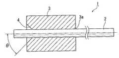
図5は、特許文献1に記載のロータを示す図であり、(a)は組立前の状態を示す側面図であり、(b)は円筒状マグネットの側断面図である。 5A and 5B are views showing a rotor described in
ロータの組立は、シャフト102の周面に点状または線状に接着剤105を塗布した上、シャフト102の一端側から円筒状マグネット101を、角度θの傾斜を有するすり鉢状溜まり溝104が形成された側から外嵌する。 In assembling the rotor, the
挿入側の軸孔103の端部にはすり鉢状溜まり溝104が存在することから、接着剤105はすり鉢状溜まり溝104の傾斜面に沿って軸孔103内面とシャフト102の間の隙間内に円滑に侵入し、両部材の接触面における広い範囲に行き渡らせることが可能で、シャフト102の円筒状マグネット101に対する引き抜き強度を高めることができる。そして嵌挿後は、はみ出した接着剤105はすり鉢状溜まり溝104内に残存するが、接着剤105は円筒状マグネット101の端部より外方には存在しないため、ロータの回転動作の障害となることはない。 Since there is a mortar-
しかしながら、この特許文献1のロータでは、円筒状マグネット101の軸孔103内面とシャフト102周面との間の隙間内に接着剤105を介在させた構成のため、軸孔103の軸中心線とシャフト102の軸中心線とが必ずしも一致せず、軸孔103の軸中心線とシャフト102の軸中心線とが一致しない場合には、ロータ回転時に回転振れが生じ、振動の原因となる。 However, in the rotor of this
このように、従来は、シャフトとロータマグネットとの間に接着剤の層を必要とするため、すきま嵌めとなり、接着剤が硬化するまでの間、ロータマグネットの軸孔中でシャフトの軸中心線がずれないように所定の位置に保持する必要があり、そのための治具等を必要とする結果、作業性が悪いという問題もあった。 As described above, conventionally, since an adhesive layer is required between the shaft and the rotor magnet, the axial center line of the shaft in the shaft hole of the rotor magnet is used until the adhesive is hardened until the adhesive is cured. There is a problem that workability is poor as a result of requiring a jig or the like for holding it at a predetermined position so as not to shift.
これに対し、マグネットの軸孔の軸中心線とシャフトの軸中心線とが一致するように固着したロータが提案されている(たとえば、特許文献2参照)。 On the other hand, a rotor that is fixed so that the axial center line of the shaft hole of the magnet coincides with the axial center line of the shaft has been proposed (see, for example, Patent Document 2).
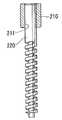
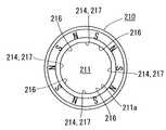
図6は特許文献2に記載のロータの一部断面を示した側面図であり、図7は図6のロータマグネットの平面図である。 6 is a side view showing a partial cross section of the rotor described in
この特許文献2においては、軸孔211の内壁面211aに、軸方向にわたる受け手段214を、内壁面211aの円周方向に複数個有し、且つこの受け手段214における頂面または頂端間を結ぶ仮想円が正円をなす構成としてある。 In this
受け手段214が軸方向にわたって備えられ、且つ仮想の正円にある複数個の弧状湾曲面216の互いに隣り合う弧状湾曲面216、216間を連設するように軸方向にわたって備えられる平らな面217として構成されている。 A flat surface 217 provided in the axial direction so that the receiving means 214 is provided in the axial direction and the arc-shaped
シャフト220は、その外周面が受け手段214によって支承され、シャフト220と弧状湾曲面216との間の隙間に接着剤が充填され、ロータマグネット210の軸孔211の軸中心線とシャフト220の軸中心線とを一致させることができると共に、強固に接着できる。 The outer peripheral surface of the
しかしながら、特許文献2に記載のロータにあっては、ロータマグネット210の軸孔211にシャフト220を挿入した後、シャフト220と弧状湾曲面216との間の隙間に接着剤を充填しているが、シャフト220と弧状湾曲面216との間の隙間は僅かなため、この隙間へ接着剤を充填する作業性が容易ではない。 However, in the rotor described in
また、シャフト220と弧状湾曲面216との間の隙間へ充填された接着剤の量を判断することが難しいという問題がある。 In addition, there is a problem that it is difficult to determine the amount of adhesive filled in the gap between the
本発明は係る問題に鑑みてなされたもので、その目的とするところは、ロータマグネットとシャフトとの嵌合における強固な固着力を得ると共に、ロータマグネットとシャフトとの間に充填される接着剤の量を容易に判断することができるロータ構造を提供することにある。 The present invention has been made in view of such problems, and an object of the present invention is to obtain a strong fixing force in the fitting between the rotor magnet and the shaft and to fill the adhesive between the rotor magnet and the shaft. It is an object of the present invention to provide a rotor structure that can easily determine the amount of the rotor.
本発明は上記の目的を達成するために、円筒状のロータマグネットと、該ロータマグネットの軸孔に嵌着されたシャフトとからなるロータ構造において、前記ロータマグネットの軸孔の断面形状が平面部と角部とから構成される正多角形であって、前記シャフトの外周面が前記軸孔の平面部に当接して嵌合し、前記角部と前記平面部と前記シャフトとの間に隙間が形成され、前記軸孔の少なくとも一端には端面に向けて漸次拡径されてテーパー状の面取り部が形成され、該テーパー状の面取り部による空間に接着剤を注入することにより、該接着剤が前記隙間に充填されてなることを特徴とする。 In order to achieve the above object, the present invention provides a rotor structure comprising a cylindrical rotor magnet and a shaft fitted in the shaft hole of the rotor magnet, wherein the cross-sectional shape of the shaft hole of the rotor magnet is a flat portion. And an outer peripheral surface of the shaft is in contact with and fitted to the flat portion of the shaft hole, and a gap is formed between the corner portion, the flat portion, and the shaft. And at least one end of the shaft hole is gradually expanded toward the end surface to form a tapered chamfered portion, and the adhesive is injected by injecting the adhesive into the space formed by the tapered chamfered portion. Is filled in the gap.
また本発明は、前記ロータマグネットに前記シャフトを圧入したときに、前記テーパー状の面取り部による空間の容積から、該面取り部による空間中にある前記シャフトの体積を差し引いた容積が、前記隙間全体の容積とほぼ等しいことを特徴とする。 In the present invention, when the shaft is press-fitted into the rotor magnet, the volume obtained by subtracting the volume of the shaft in the space by the chamfered portion from the volume of the space by the tapered chamfered portion is the entire gap. It is characterized by being approximately equal to the volume of.
また本発明は、前記正多角形の角部がR面に形成されていると共に、前記角部と前記シャフトとの距離が0.05mm以下に形成されてなることを特徴とする。 In addition, the present invention is characterized in that the corners of the regular polygon are formed on the R surface, and the distance between the corners and the shaft is 0.05 mm or less.
また本発明は、前記面取り部の軸方向からの角度は30度〜60度の範囲に形成されてなることを特徴とする。 In the present invention, the angle of the chamfered portion from the axial direction is formed in a range of 30 to 60 degrees.
本発明によれば、ロータマグネットとシャフトとの嵌合における強固な固着力を得ると共に、ロータマグネットとシャフトとの間に充填される接着剤の量を容易に判断することができるロータ構造を提供することができる。 According to the present invention, there is provided a rotor structure capable of obtaining a strong fixing force in fitting between a rotor magnet and a shaft and easily determining the amount of adhesive filled between the rotor magnet and the shaft. can do.
すなわち本願請求項1に係る発明によれば、円筒状のロータマグネットと、該ロータマグネットの軸孔に嵌着されたシャフトとからなるロータ構造において、前記ロータマグネットの軸孔の断面形状が平面部と角部とから構成される正多角形であって、前記シャフトの外周面が前記軸孔の平面部に当接して嵌合し、前記角部と前記平面部と前記シャフトとの間に隙間が形成され、前記軸孔の少なくとも一端には端面に向けて漸次拡径されてテーパー状の面取り部が形成され、該テーパー状の面取り部に接着剤を注入することにより、該接着剤が前記隙間に充填されてなるロータ構造のため、ロータマグネットの軸孔の軸中心線とシャフトの軸中心線とを一致させることができ、かつロータマグネットの軸孔とシャフトとの間に形成される隙間に充填する接着剤の注入作業が容易となる。 That is, according to the invention according to
また、シャフトがロータマグネットに圧入されているため、マグネットを所定位置に保持するための治具を必要としない。なお、シャフトと嵌合するロータマグネットの軸孔が正多角形の形状のため、シャフト圧入によるシャフトとの接触は部分接触の線接触となり、発生する応力が周方向に分散できるため、シャフト圧入による保持力を確保してもロータマグネットの割れが防止できる。 Further, since the shaft is press-fitted into the rotor magnet, a jig for holding the magnet in a predetermined position is not required. In addition, since the shaft hole of the rotor magnet fitted to the shaft is a regular polygonal shape, the contact with the shaft due to the shaft press-fitting is a partial contact line contact, and the generated stress can be dispersed in the circumferential direction. Even if the holding force is secured, the rotor magnet can be prevented from cracking.
また、本願請求項2に係る発明によれば、前記ロータマグネットに前記シャフトを圧入したときに、前記テーパー状の面取り部の容積から、該面取り部中にある前記シャフトの体積を差し引いた容積が、前記隙間全体の容積とほぼ等しくなるように形成されているため、面取り部に残存する接着剤の量を見ることによって、前記隙間充填された接着剤の量を容易に推測できる結果、接着強度の良否を判断することができる。 According to the invention of
また、本願請求項3に係る発明によれば、前記正多角形の角部がR面に形成されていると共に、前記角部と前記シャフトとの距離が0.05mm以下に形成することによって、前記面取り部に注入された接着剤が毛細管現象により前記隙間内へ侵入し、接着剤が隙間内に過大に流れ込むことなく、効率よく充填される。 According to the invention of
以下、本発明を実施するための最良の形態について図面を参照して説明する。 The best mode for carrying out the present invention will be described below with reference to the drawings.
なお、本発明は、PM型ステッピングモータにおけるロータ構造に関するものであり、ステッピングモータにおける他の部分については、その説明および図示を省略する。 The present invention relates to a rotor structure in a PM type stepping motor, and the description and illustration of the other parts of the stepping motor are omitted.
図1は、本発明によるロータ構造の一実施の形態を示す側断面図であり、ロータマグネットにシャフトを取付けた状態を示す図である。 FIG. 1 is a side sectional view showing an embodiment of a rotor structure according to the present invention, and shows a state where a shaft is attached to a rotor magnet.
図1において、ロータ構造1は、金属製の丸棒状のシャフト2とNd−Fe−B系希土類ボンド磁石からなる円筒状のロータマグネット3とから構成され、ロータマグネット3の外周面には周方向に多極着磁が施されている。 In FIG. 1, a
また、ロータマグネット3の中央には軸方向に貫通する軸孔3aが形成され、軸孔3aの軸方向に直角な面における断面形状は正六角形にて形成されている。 Further, a
正六角形に形成された軸孔3aの各角部3cは応力集中を緩和するためにR面に形成されている。また、軸孔3aの一端は端面に向けて漸次拡径されてテーパー状の面取り部4を形成している。 Each
図2は、図1のロータマグネット3を面取り部4の側から見た(図1の左側から見た)側面図である。 2 is a side view of the
また、図3は、図1のロータマグネット3を軸方向に破断させて見た側断面図である。 FIG. 3 is a sectional side view of the
本実施の形態では、ロータマグネット3を図2や図3に示すような形状としたので、シャフト2をロータマグネット3の軸孔3aに圧入すると、シャフト2の外周面は軸孔3aの平面部3bに当接して嵌合し、正六角形に形成された軸孔3aの角部3cと平面部3bとシャフト2の外周面との間には隙間3dが形成され、これによって周方向で均等に6箇所の隙間3dが形成される。 In the present embodiment, the
次に、本実施の形態のロータ構造を製造する工程について説明する。 Next, a process for manufacturing the rotor structure of the present embodiment will be described.
図4は、図1のロータ構造を製造する工程を説明する図であり、(a)はロータマグネット3にシャフト2を圧入する直前の状態を示す側面図であり、(b)はロータマグネット3にシャフト2を圧入した後に接着剤5を注入する様子を示す側面図であり、(c)は接着剤5が注入される、面取り部4による空間の容積を説明する斜視図であり、(d)は接着剤5を熱硬化させた後のロータ構造1を、面取り部4の側から見た(図4(b)の上側から見た)平面図である。 4A and 4B are diagrams illustrating a process for manufacturing the rotor structure of FIG. 1, in which FIG. 4A is a side view showing a state immediately before the
まず、図4(a)に示すように、ロータマグネット3の軸孔3aにシャフト2を圧入し、ロータマグネット3を所定の位置までスライドさせて嵌着した後、図4(b)に示すように、簡単な治具(図示せず)を用いてテーパー状の面取り部4を上にした状態に保持し、ディスペンサー(吐出機)の吐出口6から所定量の接着剤5を面取り部4による空間に注入する。 First, as shown in FIG. 4 (a), the
この接着剤5は、たとえば熱硬化性の接着剤であるエポキシ系接着剤であり、常温ではある程度の粘度を有してほとんど流れずに、面取り部4による空間に充填される。その後に加熱すると、接着剤5は流動性を増し、さらにその後に熱硬化して接着力を発揮する。 The adhesive 5 is, for example, an epoxy-based adhesive that is a thermosetting adhesive, and has a certain viscosity at room temperature and hardly flows, and is filled in the space by the chamfered
ロータマグネット3にはシャフト2が圧入されているため、面取り部4による空間の容積(以下、単に「面取り部4の容積」という)はそのシャフト2の分だけ減り、図4(c)に網掛けをして示す部分vに対して接着剤5が充填される。 Since the
なお、この時点では、接着剤5はその粘度のために軸孔3aの角部3cと平面部3bとシャフト2の外周面との間に形成された隙間3dへは流れずに面取り部4による空間に留まっている。 At this time, the adhesive 5 does not flow into the
このように面取り部4による空間に充填された接着剤5は、その後に加熱されることによって流動性を増し、毛細管現象により隙間3dへと流れて侵入し、これによって、図4(d)に示すように、隙間3d内に接着剤5が充填される。 The adhesive 5 filled in the space by the chamfered
本実施の形態では、軸孔3aの角部3cとシャフト2との間の距離が0.05mm以下になるように設定している。軸孔3aの角部3cとシャフト2との間の距離を0.05mmよりも大きくした場合、隙間3dに接着剤が流れ込み過ぎてしまうため好ましくない。これに対して、軸孔3aの角部3cとシャフト2との間の距離を0.05mm以下に設定した場合、毛細管現象により接着剤5が隙間3dに効率よく侵入して軸方向全長に亘って充填することができる。 In the present embodiment, the distance between the
しかしながら、接着剤5の種類によっては、軸孔3aの角部3cとシャフト2との間の距離が小さすぎると、隙間3dに接着剤が流れ込まなくなってしまう虞もあるし、十分な接着強度が得られない虞もある。軸孔3aの角部3cとシャフト2との間の距離はこの点を考慮して定められる。 However, depending on the type of the adhesive 5, if the distance between the
面取り部4に所定量の接着剤5を充填した後、所定の条件下で加熱して隙間3d内に接着剤5を充填させて接着剤5を硬化させる。これによってロータマグネット3とシャフト2とが固着される。 After the chamfered
本実施の形態では、面取り部4の角度(すなわちテーパ部の角度)θを45度に形成している。 In the present embodiment, the angle θ of the chamfered portion 4 (that is, the angle of the tapered portion) is formed at 45 degrees.
本実施の形態のロータ構造が使用される小型のステッピングモータの中でもデジタルカメラや携帯電話機のカメラモジュール用に用いられるステッピングモータはその外径寸法が約6mmと小さく、そのステッピングモータに使われるロータマグネットの外径寸法は3mm程度となり、極めて小さい。このため、面取り部4の角度θを小さくすると、面取り部4の半径方向長さに対して軸方向長さ(深さ)が大きくなるため、接着剤5の硬化後、面取り部4に残る接着剤5の体積が減っても上から見た見かけ上の差が小さく、減り具合が分かり難い。また、面取り部4の端面における面積が小さくなってしまうため、ディスペンサーの吐出口6からの接着剤5の注入作業が行い難くなってしまう。 Among the small stepping motors in which the rotor structure of the present embodiment is used, the stepping motor used for the camera module of a digital camera or a mobile phone has a small outer diameter of about 6 mm, and the rotor magnet used for the stepping motor The outer diameter is about 3 mm, which is extremely small. For this reason, if the angle θ of the chamfered
逆に面取り部4の角度θを大きくすると、ディスペンサーの吐出口6からの接着剤5の注入の作業性は向上するが、面取り部4の傾斜が緩やかになって接着剤5が面取り部4の傾斜を流れ難くなり、付着して残存してしまう虞がある。また、面取り部4の外周縁がロータマグネット3の外周縁に接近してしまうため、ロータマグネット3の外周縁が欠け易くなるという問題が生じる。 Conversely, when the angle θ of the chamfered
そこで、面取り部4の角度θは30度〜60度の範囲に形成することが望ましく、面取り部4の角度θを45度にすると、半径方向の長さと軸方向の長さ(深さ)とが等しいため、接着剤5が隙間3dへと流れていく過程で面取り部4による空間の残存量が減少していく様子がわかり易く、一方、面取り部4がある程度の急勾配を形成しているので、接着剤5が面取り部4に付着して残存することも避けられ、望ましい。 Therefore, the angle θ of the chamfered
接着剤5を加熱して硬化させた後、面取り部4に残存する接着剤5の量を見ることによって隙間3dに充填された接着剤5の量を推測し、接着強度の良否を判定することができるようにした。 After the adhesive 5 is heated and cured, the amount of the adhesive 5 filled in the
すなわち、本実施の形態では、面取り部4による空間の容積から、面取り部4による空間中にあるシャフト2の体積を差し引いた容積が、隙間3d全体の容積と等しくなるように形成しており、このようにすることによって、面取り部4に残存する接着剤5の量を見ることによって隙間3dに充填された接着剤5の量を概略推測することができ、この結果
により、接着強度の良否を判断することができる。That is, in this embodiment, the volume obtained by subtracting the volume of the
なお、上述の実施の形態では、軸孔3aの断面形状は正六角形にて形成されているが、本発明はこれに限定されるものではなく、正三角形、正四角形、正八角形などの正多角形であっても良く、隙間3dに充填される接着剤5の粘度は軸孔3aの形状に対応して適宜選択される。 In the above-described embodiment, the cross-sectional shape of the
また、ロータマグネット3は希土類ボンド磁石に限定されるものではなく、フェライトボンド磁石であっても、焼結磁石であっても勿論良い。 Further, the
上述のように、軸孔3aの一端が端面に向けて漸次拡径されてテーパー状の面取り部4を形成し、このテーパー状の面取り部4に接着剤5を注入することにより、ロータマグネット3の軸孔3aとシャフト2の軸中心線を一致させることができると共に、充填する接着剤5の注入作業が容易となる。 As described above, one end of the
1 ロータ構造
2 シャフト
3 ロータマグネット
4 面取り部
5 接着剤
6 吐出機の吐出口DESCRIPTION OF
Claims (4)
Translated fromJapanese前記ロータマグネットの軸孔の断面形状が平面部と角部とから構成される正多角形であって、
前記シャフトの外周面が前記軸孔の平面部に当接して嵌合し、前記角部と前記平面部と前記シャフトとの間に隙間が形成され、前記軸孔の少なくとも一端には端面に向けて漸次拡径されてテーパー状の面取り部が形成され、該テーパー状の面取り部による空間に接着剤を注入することにより、該接着剤が前記隙間に充填されてなることを特徴とするロータ構造。In a rotor structure consisting of a cylindrical rotor magnet and a shaft fitted in the shaft hole of the rotor magnet,
A cross-sectional shape of the shaft hole of the rotor magnet is a regular polygon composed of a plane portion and a corner portion,
The outer peripheral surface of the shaft is in contact with and fitted to the flat portion of the shaft hole, and a gap is formed between the corner portion, the flat portion, and the shaft, and at least one end of the shaft hole faces the end surface. The rotor structure is characterized in that a tapered chamfered portion is formed by gradually expanding the diameter, and the adhesive is filled into the gap by injecting the adhesive into a space formed by the tapered chamfered portion. .
Priority Applications (2)
| Application Number | Priority Date | Filing Date | Title |
|---|---|---|---|
| JP2007167399AJP2009011019A (en) | 2007-06-26 | 2007-06-26 | Rotor structure |
| US12/214,153US7642689B2 (en) | 2007-06-26 | 2008-06-17 | Rotor structure |
Applications Claiming Priority (1)
| Application Number | Priority Date | Filing Date | Title |
|---|---|---|---|
| JP2007167399AJP2009011019A (en) | 2007-06-26 | 2007-06-26 | Rotor structure |
Publications (1)
| Publication Number | Publication Date |
|---|---|
| JP2009011019Atrue JP2009011019A (en) | 2009-01-15 |
Family
ID=40159542
Family Applications (1)
| Application Number | Title | Priority Date | Filing Date |
|---|---|---|---|
| JP2007167399APendingJP2009011019A (en) | 2007-06-26 | 2007-06-26 | Rotor structure |
Country Status (2)
| Country | Link |
|---|---|
| US (1) | US7642689B2 (en) |
| JP (1) | JP2009011019A (en) |
Cited By (1)
| Publication number | Priority date | Publication date | Assignee | Title |
|---|---|---|---|---|
| JP2011024351A (en)* | 2009-07-16 | 2011-02-03 | Nippon Densan Corp | Spindle motor, disk drive, and manufacturing method for spindle motor |
Families Citing this family (14)
| Publication number | Priority date | Publication date | Assignee | Title |
|---|---|---|---|---|
| GB2467967B (en)* | 2009-02-24 | 2015-04-22 | Dyson Technology Ltd | Rotor assembly |
| DE112011100698T5 (en)* | 2010-02-27 | 2013-03-28 | Mbs Engineering Llc | Improved magnet rotor device with improved physical strength |
| DE102010023813A1 (en)* | 2010-06-15 | 2011-12-15 | Maxon Motor Ag | Small electric motor |
| JP5653746B2 (en)* | 2010-12-24 | 2015-01-14 | ミネベア株式会社 | Stepping motor for meter |
| EP2670031B1 (en)* | 2011-01-26 | 2020-07-01 | Makita Corporation | Brushless motor for power tool |
| GB2487921B (en) | 2011-02-08 | 2013-06-12 | Dyson Technology Ltd | Rotor for a turbomachine |
| JP2013027075A (en)* | 2011-07-15 | 2013-02-04 | Nidec Sankyo Corp | Rotor, motor, and method of manufacturing rotor |
| US20130053489A1 (en)* | 2011-08-22 | 2013-02-28 | Robert R. Gallucci | Polyetherimide compositions and methods for the manufacture and use thereof |
| KR102234696B1 (en) | 2014-03-17 | 2021-04-02 | 엔에이치엔 주식회사 | On-line card game server |
| CN106469964B (en) | 2016-10-31 | 2018-05-08 | 北京金风科创风电设备有限公司 | Permanent magnet motor magnetic pole protects coating moulding process and process equipment |
| CN106787509B (en)* | 2016-12-22 | 2018-10-09 | 宁波韵升股份有限公司 | A kind of production method of motor rotor component |
| TWI645655B (en)* | 2017-07-04 | 2018-12-21 | 建準電機工業股份有限公司 | Rotor of inner-rotor motor |
| WO2019233596A1 (en)* | 2018-06-08 | 2019-12-12 | Pierburg Pump Technology Gmbh | Electric motor |
| KR102759703B1 (en)* | 2019-11-26 | 2025-02-03 | 삼성전자주식회사 | Brushless Direct Current Motor |
Citations (6)
| Publication number | Priority date | Publication date | Assignee | Title |
|---|---|---|---|---|
| JPS5063505U (en)* | 1973-10-12 | 1975-06-10 | ||
| JPS5084816A (en)* | 1973-11-30 | 1975-07-09 | ||
| JPS6188477U (en)* | 1984-11-15 | 1986-06-09 | ||
| JPH04168967A (en)* | 1990-10-30 | 1992-06-17 | Matsushita Electric Ind Co Ltd | stepping motor rotor |
| JPH0497445U (en)* | 1991-01-11 | 1992-08-24 | ||
| JP2006158136A (en)* | 2004-11-30 | 2006-06-15 | Nidec Sankyo Corp | Small motor |
Family Cites Families (13)
| Publication number | Priority date | Publication date | Assignee | Title |
|---|---|---|---|---|
| JPH0497445A (en) | 1990-08-16 | 1992-03-30 | Nec Corp | Diagnostic system for information processor |
| JP3139195B2 (en) | 1993-02-17 | 2001-02-26 | 松下電器産業株式会社 | PM type stepping motor rotor |
| JPH0716558A (en) | 1993-06-18 | 1995-01-20 | Riide Purantsu:Kk | Garbage treatment method and apparatus therefor |
| JP3148588B2 (en) | 1995-08-14 | 2001-03-19 | 三洋電機株式会社 | Permanent magnet type inner rotor and small motor |
| JPH09200983A (en) | 1996-01-12 | 1997-07-31 | Tokyo Ferrite Seizo Kk | Rotor for motor |
| JPH10201152A (en) | 1997-01-17 | 1998-07-31 | Mitsubishi Electric Corp | Permanent magnet rotor and manufacturing method thereof |
| DE19914021C2 (en)* | 1999-03-19 | 2002-01-31 | Siemens Ag | Multi-pole, permanently excited rotor for a rotating electrical machine and method for producing such a rotor |
| US6800967B2 (en)* | 2000-06-09 | 2004-10-05 | Neomax Co., Ltd. | Integrated magnet body and motor incorporating it |
| JP2004120891A (en) | 2002-09-26 | 2004-04-15 | Hitachi Metals Ltd | Ferrite magnet and rotating machine |
| JP4267309B2 (en)* | 2002-12-03 | 2009-05-27 | 株式会社ジェイテクト | Adhesive structure |
| JP4102749B2 (en) | 2003-12-24 | 2008-06-18 | オークマ株式会社 | Reluctance motor rotor |
| US7061152B2 (en)* | 2004-10-25 | 2006-06-13 | Novatorque, Inc. | Rotor-stator structure for electrodynamic machines |
| JP4763320B2 (en)* | 2005-03-09 | 2011-08-31 | 三菱電機株式会社 | Synchronous induction motor rotor and compressor |
- 2007
- 2007-06-26JPJP2007167399Apatent/JP2009011019A/enactivePending
- 2008
- 2008-06-17USUS12/214,153patent/US7642689B2/enactiveActive
Patent Citations (6)
| Publication number | Priority date | Publication date | Assignee | Title |
|---|---|---|---|---|
| JPS5063505U (en)* | 1973-10-12 | 1975-06-10 | ||
| JPS5084816A (en)* | 1973-11-30 | 1975-07-09 | ||
| JPS6188477U (en)* | 1984-11-15 | 1986-06-09 | ||
| JPH04168967A (en)* | 1990-10-30 | 1992-06-17 | Matsushita Electric Ind Co Ltd | stepping motor rotor |
| JPH0497445U (en)* | 1991-01-11 | 1992-08-24 | ||
| JP2006158136A (en)* | 2004-11-30 | 2006-06-15 | Nidec Sankyo Corp | Small motor |
Cited By (1)
| Publication number | Priority date | Publication date | Assignee | Title |
|---|---|---|---|---|
| JP2011024351A (en)* | 2009-07-16 | 2011-02-03 | Nippon Densan Corp | Spindle motor, disk drive, and manufacturing method for spindle motor |
Also Published As
| Publication number | Publication date |
|---|---|
| US20090001826A1 (en) | 2009-01-01 |
| US7642689B2 (en) | 2010-01-05 |
Similar Documents
| Publication | Publication Date | Title |
|---|---|---|
| JP2009011019A (en) | Rotor structure | |
| JP4143631B2 (en) | Manufacturing method of rotor | |
| KR101220381B1 (en) | Interior permanent magnet motor and manufacturing method for the same | |
| US7560842B2 (en) | Permanent magnet type rotating electric machine capable of suppressing deformation of rotor core | |
| JP4095795B2 (en) | Method of manufacturing rotor of synchronous machine having permanent magnet and rotor manufactured by the method | |
| JP5505281B2 (en) | Rotating electrical machine rotor | |
| US20050225190A1 (en) | Rotor for brushless motor and brushless motor | |
| JP6836842B2 (en) | Rotor and motor including it | |
| JP3487143B2 (en) | Rotary electric machine rotor and method for manufacturing rotary electric machine rotor | |
| JP6583105B2 (en) | Coil end forming method | |
| JP2005012859A (en) | Electric motor rotor and manufacturing method thereof | |
| US20130241319A1 (en) | Magnet plate for linear motor for preventing misalignment of magnets | |
| US20020117923A1 (en) | Permanent magnet embedded motor, rotor for motor and method for manufacturing motor and rotor | |
| JPH10201152A (en) | Permanent magnet rotor and manufacturing method thereof | |
| JP2005269804A (en) | Rotating electric machine | |
| JP6813009B2 (en) | How to manufacture the rotor | |
| JP2006288200A (en) | Method for manufacturing permanent magnet rotor and motor | |
| JP6486122B2 (en) | Wall body repair method | |
| JP2000180661A (en) | Ferrule and its fixing method | |
| JP4613654B2 (en) | Motor and manufacturing method thereof | |
| JP2007300711A (en) | Motor and manufacturing method therefor | |
| JP2015228732A (en) | Fixing structure and fixing method of permanent magnet, motor, and permanent magnet | |
| JPH0956090A (en) | Field device for rotating electric machine | |
| US11368062B2 (en) | Rotor structure and rotor structure manufacturing method | |
| JPH07322576A (en) | Method of manufacturing permanent magnet rotor |
Legal Events
| Date | Code | Title | Description |
|---|---|---|---|
| A621 | Written request for application examination | Free format text:JAPANESE INTERMEDIATE CODE: A621 Effective date:20100413 | |
| A977 | Report on retrieval | Free format text:JAPANESE INTERMEDIATE CODE: A971007 Effective date:20120510 | |
| A131 | Notification of reasons for refusal | Free format text:JAPANESE INTERMEDIATE CODE: A131 Effective date:20120515 | |
| A521 | Request for written amendment filed | Free format text:JAPANESE INTERMEDIATE CODE: A523 Effective date:20120705 | |
| A131 | Notification of reasons for refusal | Free format text:JAPANESE INTERMEDIATE CODE: A131 Effective date:20120821 | |
| A521 | Request for written amendment filed | Free format text:JAPANESE INTERMEDIATE CODE: A523 Effective date:20121009 | |
| A02 | Decision of refusal | Free format text:JAPANESE INTERMEDIATE CODE: A02 Effective date:20121127 |