JP2009006152A - Method and apparatus for fixing graft in bone tunnel - Google Patents
Method and apparatus for fixing graft in bone tunnelDownload PDFInfo
- Publication number
- JP2009006152A JP2009006152AJP2008181244AJP2008181244AJP2009006152AJP 2009006152 AJP2009006152 AJP 2009006152AJP 2008181244 AJP2008181244 AJP 2008181244AJP 2008181244 AJP2008181244 AJP 2008181244AJP 2009006152 AJP2009006152 AJP 2009006152A
- Authority
- JP
- Japan
- Prior art keywords
- bone tunnel
- bone
- guide rod
- frame member
- tunnel
- Prior art date
- Legal status (The legal status is an assumption and is not a legal conclusion. Google has not performed a legal analysis and makes no representation as to the accuracy of the status listed.)
- Granted
Links
- 210000000988bone and boneAnatomy0.000titleclaimsabstractdescription325
- 238000000034methodMethods0.000titleclaimsabstractdescription68
- 210000003041ligamentAnatomy0.000claimsabstractdescription73
- 230000001054cortical effectEffects0.000claimsabstractdescription10
- 238000005553drillingMethods0.000claimsdescription41
- 238000003780insertionMethods0.000claimsdescription37
- 230000037431insertionEffects0.000claimsdescription37
- 230000002745absorbentEffects0.000claimsdescription16
- 239000002250absorbentSubstances0.000claimsdescription16
- 230000037118bone strengthEffects0.000claimsdescription3
- 230000000149penetrating effectEffects0.000claimsdescription3
- 230000000717retained effectEffects0.000claims2
- 210000002303tibiaAnatomy0.000abstractdescription40
- 238000010586diagramMethods0.000description23
- 239000007943implantSubstances0.000description22
- 238000007634remodelingMethods0.000description20
- 210000000689upper legAnatomy0.000description9
- 210000001519tissueAnatomy0.000description7
- 210000000629knee jointAnatomy0.000description6
- 230000006378damageEffects0.000description3
- 230000000694effectsEffects0.000description3
- 210000002435tendonAnatomy0.000description3
- 210000001264anterior cruciate ligamentAnatomy0.000description2
- 208000014674injuryDiseases0.000description2
- 210000003127kneeAnatomy0.000description2
- 238000001356surgical procedureMethods0.000description2
- 206010024453Ligament sprainDiseases0.000description1
- 241000124008MammaliaSpecies0.000description1
- 208000010040Sprains and StrainsDiseases0.000description1
- 208000027418Wounds and injuryDiseases0.000description1
- 230000001154acute effectEffects0.000description1
- 238000004873anchoringMethods0.000description1
- 230000009286beneficial effectEffects0.000description1
- 230000015572biosynthetic processEffects0.000description1
- 230000035876healingEffects0.000description1
- 239000000463materialSubstances0.000description1
- 238000005204segregationMethods0.000description1
- 238000000926separation methodMethods0.000description1
- 210000000323shoulder jointAnatomy0.000description1
- 230000006641stabilisationEffects0.000description1
- 238000011105stabilizationMethods0.000description1
- 230000008736traumatic injuryEffects0.000description1
Images


Classifications
- A—HUMAN NECESSITIES
- A61—MEDICAL OR VETERINARY SCIENCE; HYGIENE
- A61B—DIAGNOSIS; SURGERY; IDENTIFICATION
- A61B17/00—Surgical instruments, devices or methods
- A61B17/16—Instruments for performing osteoclasis; Drills or chisels for bones; Trepans
- A61B17/17—Guides or aligning means for drills, mills, pins or wires
- A61B17/1714—Guides or aligning means for drills, mills, pins or wires for applying tendons or ligaments
- A—HUMAN NECESSITIES
- A61—MEDICAL OR VETERINARY SCIENCE; HYGIENE
- A61B—DIAGNOSIS; SURGERY; IDENTIFICATION
- A61B17/00—Surgical instruments, devices or methods
- A61B17/16—Instruments for performing osteoclasis; Drills or chisels for bones; Trepans
- A61B17/17—Guides or aligning means for drills, mills, pins or wires
- A61B17/1739—Guides or aligning means for drills, mills, pins or wires specially adapted for particular parts of the body
- A61B17/1764—Guides or aligning means for drills, mills, pins or wires specially adapted for particular parts of the body for the knee
- A—HUMAN NECESSITIES
- A61—MEDICAL OR VETERINARY SCIENCE; HYGIENE
- A61F—FILTERS IMPLANTABLE INTO BLOOD VESSELS; PROSTHESES; DEVICES PROVIDING PATENCY TO, OR PREVENTING COLLAPSING OF, TUBULAR STRUCTURES OF THE BODY, e.g. STENTS; ORTHOPAEDIC, NURSING OR CONTRACEPTIVE DEVICES; FOMENTATION; TREATMENT OR PROTECTION OF EYES OR EARS; BANDAGES, DRESSINGS OR ABSORBENT PADS; FIRST-AID KITS
- A61F2/00—Filters implantable into blood vessels; Prostheses, i.e. artificial substitutes or replacements for parts of the body; Appliances for connecting them with the body; Devices providing patency to, or preventing collapsing of, tubular structures of the body, e.g. stents
- A61F2/02—Prostheses implantable into the body
- A61F2/08—Muscles; Tendons; Ligaments
- A61F2/0805—Implements for inserting tendons or ligaments
- A—HUMAN NECESSITIES
- A61—MEDICAL OR VETERINARY SCIENCE; HYGIENE
- A61F—FILTERS IMPLANTABLE INTO BLOOD VESSELS; PROSTHESES; DEVICES PROVIDING PATENCY TO, OR PREVENTING COLLAPSING OF, TUBULAR STRUCTURES OF THE BODY, e.g. STENTS; ORTHOPAEDIC, NURSING OR CONTRACEPTIVE DEVICES; FOMENTATION; TREATMENT OR PROTECTION OF EYES OR EARS; BANDAGES, DRESSINGS OR ABSORBENT PADS; FIRST-AID KITS
- A61F2/00—Filters implantable into blood vessels; Prostheses, i.e. artificial substitutes or replacements for parts of the body; Appliances for connecting them with the body; Devices providing patency to, or preventing collapsing of, tubular structures of the body, e.g. stents
- A61F2/02—Prostheses implantable into the body
- A61F2/08—Muscles; Tendons; Ligaments
- A61F2/0811—Fixation devices for tendons or ligaments
- A—HUMAN NECESSITIES
- A61—MEDICAL OR VETERINARY SCIENCE; HYGIENE
- A61B—DIAGNOSIS; SURGERY; IDENTIFICATION
- A61B17/00—Surgical instruments, devices or methods
- A61B17/16—Instruments for performing osteoclasis; Drills or chisels for bones; Trepans
- A61B17/1637—Hollow drills or saws producing a curved cut, e.g. cylindrical
- A—HUMAN NECESSITIES
- A61—MEDICAL OR VETERINARY SCIENCE; HYGIENE
- A61B—DIAGNOSIS; SURGERY; IDENTIFICATION
- A61B17/00—Surgical instruments, devices or methods
- A61B17/16—Instruments for performing osteoclasis; Drills or chisels for bones; Trepans
- A61B17/1662—Instruments for performing osteoclasis; Drills or chisels for bones; Trepans for particular parts of the body
- A61B17/1675—Instruments for performing osteoclasis; Drills or chisels for bones; Trepans for particular parts of the body for the knee
- A—HUMAN NECESSITIES
- A61—MEDICAL OR VETERINARY SCIENCE; HYGIENE
- A61B—DIAGNOSIS; SURGERY; IDENTIFICATION
- A61B90/00—Instruments, implements or accessories specially adapted for surgery or diagnosis and not covered by any of the groups A61B1/00 - A61B50/00, e.g. for luxation treatment or for protecting wound edges
- A61B90/03—Automatic limiting or abutting means, e.g. for safety
- A61B2090/033—Abutting means, stops, e.g. abutting on tissue or skin
- A61B2090/034—Abutting means, stops, e.g. abutting on tissue or skin abutting on parts of the device itself
- A—HUMAN NECESSITIES
- A61—MEDICAL OR VETERINARY SCIENCE; HYGIENE
- A61B—DIAGNOSIS; SURGERY; IDENTIFICATION
- A61B90/00—Instruments, implements or accessories specially adapted for surgery or diagnosis and not covered by any of the groups A61B1/00 - A61B50/00, e.g. for luxation treatment or for protecting wound edges
- A61B90/06—Measuring instruments not otherwise provided for
- A61B2090/062—Measuring instruments not otherwise provided for penetration depth
- A—HUMAN NECESSITIES
- A61—MEDICAL OR VETERINARY SCIENCE; HYGIENE
- A61F—FILTERS IMPLANTABLE INTO BLOOD VESSELS; PROSTHESES; DEVICES PROVIDING PATENCY TO, OR PREVENTING COLLAPSING OF, TUBULAR STRUCTURES OF THE BODY, e.g. STENTS; ORTHOPAEDIC, NURSING OR CONTRACEPTIVE DEVICES; FOMENTATION; TREATMENT OR PROTECTION OF EYES OR EARS; BANDAGES, DRESSINGS OR ABSORBENT PADS; FIRST-AID KITS
- A61F2/00—Filters implantable into blood vessels; Prostheses, i.e. artificial substitutes or replacements for parts of the body; Appliances for connecting them with the body; Devices providing patency to, or preventing collapsing of, tubular structures of the body, e.g. stents
- A61F2/02—Prostheses implantable into the body
- A61F2/08—Muscles; Tendons; Ligaments
- A61F2/0811—Fixation devices for tendons or ligaments
- A61F2002/0847—Mode of fixation of anchor to tendon or ligament
- A61F2002/087—Anchor integrated into tendons, e.g. bone blocks, integrated rings
- A—HUMAN NECESSITIES
- A61—MEDICAL OR VETERINARY SCIENCE; HYGIENE
- A61F—FILTERS IMPLANTABLE INTO BLOOD VESSELS; PROSTHESES; DEVICES PROVIDING PATENCY TO, OR PREVENTING COLLAPSING OF, TUBULAR STRUCTURES OF THE BODY, e.g. STENTS; ORTHOPAEDIC, NURSING OR CONTRACEPTIVE DEVICES; FOMENTATION; TREATMENT OR PROTECTION OF EYES OR EARS; BANDAGES, DRESSINGS OR ABSORBENT PADS; FIRST-AID KITS
- A61F2/00—Filters implantable into blood vessels; Prostheses, i.e. artificial substitutes or replacements for parts of the body; Appliances for connecting them with the body; Devices providing patency to, or preventing collapsing of, tubular structures of the body, e.g. stents
- A61F2/02—Prostheses implantable into the body
- A61F2/08—Muscles; Tendons; Ligaments
- A61F2/0811—Fixation devices for tendons or ligaments
- A61F2002/0876—Position of anchor in respect to the bone
- A61F2002/0882—Anchor in or on top of a bone tunnel, i.e. a hole running through the entire bone
Landscapes
- Health & Medical Sciences (AREA)
- Life Sciences & Earth Sciences (AREA)
- Orthopedic Medicine & Surgery (AREA)
- Veterinary Medicine (AREA)
- Animal Behavior & Ethology (AREA)
- Oral & Maxillofacial Surgery (AREA)
- Surgery (AREA)
- Engineering & Computer Science (AREA)
- Biomedical Technology (AREA)
- Heart & Thoracic Surgery (AREA)
- Public Health (AREA)
- General Health & Medical Sciences (AREA)
- Rheumatology (AREA)
- Cardiology (AREA)
- Vascular Medicine (AREA)
- Rehabilitation Therapy (AREA)
- Dentistry (AREA)
- Nuclear Medicine, Radiotherapy & Molecular Imaging (AREA)
- Transplantation (AREA)
- Medical Informatics (AREA)
- Molecular Biology (AREA)
- Surgical Instruments (AREA)
- Prostheses (AREA)
Abstract
Description
Translated fromJapanese本特許出願は、グレゴリー・ウィトカー(Gregory Whittakaer)により2001年3月13日付けで出願された、移植体を脛骨トンネル内に固定する方法及び装置(METHOD AND APPARATUS FOR FIXING A GRAFT IN A TIBIAL TUNNEL)という名称の先の係属中の米国仮特許出願第60/275,431号(弁護士事件番号第MIT−ZZ号 PROV)の利益を主張するものであり、その特許出願の内容は参考として引用し本明細書に含めてある。 This patent application is filed March 13, 2001, by Gregory Whittakaer, and a method and apparatus for fixing an implant in a tibial tunnel. Claims the benefit of previously pending US provisional patent application No. 60 / 275,431 (lawyer case number MIT-ZZ PROV), the contents of which are incorporated by reference. It is included in the description.
本発明は、全体として、外科的方法及び外科用装置、より具体的には、移植体を骨トンネル内に固定する方法及び装置に関する。 The present invention relates generally to surgical methods and surgical devices, and more particularly to methods and devices for securing an implant in a bone tunnel.
靭帯、腱及び(又は)その他の柔軟な組織が身体内のその関係した骨から完全に、又は部分的に分離することは、比較的一般的な損傷である。組織の分離は、仕事に関係した活動、運動中の活動又はその他の多くの状況及び(又は)活動の任意の1つの間における転倒、過度の伸張のような事故の結果として生ずる可能性がある。かかる損傷は、全体として、過剰な応力が組織に加わる結果である。 It is a relatively common injury that ligaments, tendons and / or other flexible tissues are completely or partially separated from their associated bone in the body. Organizational segregation can occur as a result of an accident such as a fall, excessive stretching during any work-related activity, exercise activity or many other situations and / or any one of activities . Such damage as a whole is a result of excessive stress being applied to the tissue.
一般的に「捻挫」という一般的な語で表現される部分的な分離の場合、癒合過程の間、損傷部分を不当な応力に曝さないように所定の十分な時間及び注意が払われるならば、損傷は自然に治癒することが多い。しかし、靭帯又は腱がその関係した1つ又は複数の骨から完全に分離した場合、又は外傷の損傷の結果として切断されたならば、部分的又は永久的な身体障害が生ずるであろう。都合の良いことに、かかる分離した組織を再度取り付け且つ(又は)ひどく損傷した組織を完全に置換するため多数の外科的方法が存在する。 In the case of partial separation, commonly expressed in the general term “sprain”, if sufficient time and care is taken to avoid exposing the damaged part to undue stress during the healing process Damage often heals spontaneously. However, if the ligament or tendon is completely separated from its associated bone or bones, or if it is cut as a result of traumatic injury, partial or permanent disability will occur. Conveniently, there are a number of surgical methods to reattach such detached tissue and / or completely replace severely damaged tissue.
かかる方法の1つは、ステープル、縫合糸及び(又は)海綿状骨ねじのような「従来の」取り付け装置を使用して分離した組織を再度取り付けることを含む。かかる従来の取り付け装置は、また、腱又は靭帯移植体(身体の他の部分から採取した自家組織で形成されることが多い)を1つ又は複数の所望の骨に取り付けるためにも使用されている。 One such method involves reattaching the separated tissue using “conventional” attachment devices such as staples, sutures and / or cancellous bone screws. Such conventional attachment devices are also used to attach tendon or ligament grafts (often formed with autologous tissue taken from other parts of the body) to one or more desired bones. Yes.
別の方法は、ジェラルド・A・ボーマン(Jerald A.Bowman)らに対して1990年8月21日付けで発行された米国特許第4,950,270号に記載されている。この方法において、人間の膝の損傷した前十字形靭帯(「ACL」)は、最初に、前十字形靭帯の通常の取り付け箇所にて脛骨及び大腿骨に骨トンネルを形成することにより置換される。次に、その一端に骨ブロックを有する移植体靭帯は、骨トンネルに嵌まり得るような寸法とされている。次に、縫合糸を骨ブロックに取り付け、その後、縫合糸を脛骨トンネルに、次に、大腿骨トンネルに通す。次に、骨ブロックを脛骨トンネルを通じて上方に進めて縫合糸を使用して大腿骨トンネル内に入れる。これが行われたとき、移植体靭帯は、膝関節の内部を横切って大腿骨トンネルを出て後方に戻り、次に、脛骨トンネルから外方に出る。移植体靭帯の自由端は、脛骨の前側部にて脛骨外に位置している。次に、骨ブロックを緊密な締嵌めによって所望位置に確実に係止し得るように骨ブロックと大腿骨トンネルとの間に骨ねじを挿入する。最後に、移植体靭帯の自由端を脛骨に確実に取り付ける。 Another method is described in U.S. Pat. No. 4,950,270 issued August 21, 1990 to Jerald A. Bowman et al. In this way, the damaged anterior cruciate ligament (“ACL”) of the human knee is first replaced by forming a bone tunnel in the tibia and femur at the normal attachment location of the anterior cruciate ligament. . Next, a graft ligament having a bone block at one end is dimensioned to fit into a bone tunnel. The suture is then attached to the bone block, after which the suture is passed through the tibial tunnel and then through the femoral tunnel. The bone block is then advanced upward through the tibial tunnel and placed into the femoral tunnel using a suture. When this is done, the graft ligament traverses the interior of the knee joint, exits the femoral tunnel and returns posteriorly, and then exits outward from the tibial tunnel. The free end of the graft ligament is located outside the tibia at the anterior side of the tibia. A bone screw is then inserted between the bone block and the femoral tunnel to ensure that the bone block can be securely locked in the desired position with a tight fit. Finally, securely attach the free end of the graft ligament to the tibia.
1992年9月15日付けでE・マーロウ ゴブル(E.Marlowe Goble)に対して発行された米国特許第5,147,362号には、整合した大腿骨トンネル及
び脛骨トンネルが人間の膝に形成される方法が開示されている。移植体靭帯が取り付けられた骨ブロックは、脛骨トンネル及び大腿骨トンネルを通って大腿骨トンネルの盲端まで進め、その盲端にて、ブロックをアンカーによって所要位置に固定する。移植体靭帯は、脛骨トンネル外に伸び、また、その基端は、ステープル等によって脛骨皮質に取り付けられる。これと代替的に、靭帯の基端は、アンカー又は締嵌めねじによって脛骨トンネル内に固定してもよい。U.S. Pat. No. 5,147,362 issued to E. Marlowe Goble on September 15, 1992, shows the formation of aligned femoral and tibial tunnels in a human knee A method is disclosed. The bone block to which the graft ligament is attached is advanced through the tibial tunnel and the femoral tunnel to the blind end of the femoral tunnel, where the block is fixed in place by an anchor. The graft ligament extends outside the tibial tunnel, and its proximal end is attached to the tibial cortex by staples or the like. Alternatively, the proximal end of the ligament may be secured in the tibial tunnel with an anchor or an interference screw.
色々な型式の靭帯及び(又は)縫合アンカー及びその他の物を骨に取り付けるためのアンカーも当該技術分野にて周知である。これら装置の多くは、米国特許第4,898,156号、米国特許第4,899,743号、米国特許第4,968,315号、米国特許第5,356,413号及び米国特許第5,372,599号に記載されている。 Various types of ligaments and / or suture anchors and other anchors for attaching other objects to bone are also well known in the art. Many of these devices are described in U.S. Pat. No. 4,898,156, U.S. Pat. No. 4,899,743, U.S. Pat. No. 4,968,315, U.S. Pat. No. 5,356,413 and U.S. Pat. , 372,599.
骨ブロックを骨トンネル内に定着する1つの既知の方法は、ピン、ねじ又はロッドを骨トンネルを横断するように骨内に押し込み、骨ブロックと相互作用し、これにより骨ブロックを骨トンネル内で「交差状にピン止めする」交差状にピン止めすることによるものである。 One known method of anchoring a bone block within a bone tunnel is to push a pin, screw or rod into the bone across the bone tunnel and interact with the bone block, thereby causing the bone block to move within the bone tunnel. "Pin in cross" is by pinning in cross.
この点に関して、クロスピン(すなわち、上述したピン、ねじ又はロッド)は全体として予め穿孔した横通路内に配置されることを理解すべきである。骨ブロックを骨トンネル内で適正に交差状にピン止めするため、一般に、ドリルガイドが使用される。ドリルガイドは、横通路が適宜なトンネル部分、従って、骨ブロックと直交するように、横通路が骨内に配置されることを保証するような働きをする。かかる横穿孔を行うために使用されるドリルガイドは、米国特許第4,901,711号、米国特許第4,985,032号、米国特許第5,152,764号、米国特許第5,350,380号及び米国特許第5,431,651号に記載されている。 In this regard, it should be understood that the cross pin (ie, the pin, screw or rod described above) is generally disposed within a pre-drilled lateral passage. A drill guide is generally used to properly pin the bone block in the bone tunnel in a properly crossed manner. The drill guide serves to ensure that the transverse passage is positioned in the bone so that the transverse passage is orthogonal to the appropriate tunnel portion and thus the bone block. Drill guides used to perform such side drilling are US Pat. No. 4,901,711, US Pat. No. 4,985,032, US Pat. No. 5,152,764, US Pat. No. 5,350. 380 and U.S. Pat. No. 5,431,651.
交差状にピン止めすることが論じられるその他の特許は、米国特許第3,973,277号、米国特許第5,004,474号、米国特許第5,067,962号、米国特許第5,266,075号、米国特許第5,356,435号、米国特許第5,376,119号、米国特許第5,393,302号及び米国特許第5,397,356号を含む。 Other patents discussed to be pinned in a cross are US Pat. No. 3,973,277, US Pat. No. 5,004,474, US Pat. No. 5,067,962, US Pat. 266,075, US Pat. No. 5,356,435, US Pat. No. 5,376,119, US Pat. No. 5,393,302 and US Pat. No. 5,397,356.
移植体靭帯を大腿骨トンネル内に固定する交差状ピン止め方法及び装置が現在、存在する。しかし、当該技術にて現在、既知の大腿骨交差状ピン止め方法及び装置は、異なる考慮を必要とする、クロスピンを脛骨トンネル内で使用することは対象としていない。これら考慮事項として、解剖学的な幾何学的形態、骨の形態、骨の質等がある。 There are currently crossed pinning methods and devices that secure the graft ligaments within the femoral tunnel. However, the femoral cross pinning methods and devices currently known in the art are not directed to the use of cross pins in tibial tunnels that require different considerations. These considerations include anatomical geometry, bone morphology, bone quality, and the like.
従って、移植体を脛骨トンネル内に固定し得るように少なくとも1つのクロスピンを位置決めする方法及び装置が必要とされている。
また、方法が完了したとき、クロスピンが脛骨平部に隣接して脛骨の皮質部分内に配置されるように少なくとも1つのクロスピンを脛骨トンネルを横断して位置決めする方法及び装置も必要とされている。Accordingly, there is a need for a method and apparatus for positioning at least one cross pin so that an implant can be secured within a tibial tunnel.
There is also a need for a method and apparatus for positioning at least one cross pin across a tibial tunnel such that when the method is completed, the cross pin is positioned within the cortical portion of the tibia adjacent to the tibia flat. .
このため、本発明の1つの目的は、移植体を脛骨トンネル内で固定し得るように少なくとも1つのクロスピンを位置決めする新規な方法及び装置を提供することである。
本発明の別の目的は、方法が完了したとき、クロスピンがけい骨内に配置され、より好ましくは、脛骨平部に隣接して脛骨の皮質部分内に配置されるように少なくとも1つのクロスピンを脛骨トンネルを横断して位置決めする新規な方法及び装置を提供することである。Thus, one object of the present invention is to provide a novel method and apparatus for positioning at least one cross pin so that an implant can be secured within a tibial tunnel.
Another object of the present invention is to provide at least one crosspin so that when the method is complete, the crosspin is placed in the tibia, more preferably in the cortical portion of the tibia adjacent to the tibia flat. It is to provide a novel method and apparatus for positioning across a tibial tunnel.
本発明の上記及びその他の目的は、移植体を骨トンネル内に固定する新規な方法及び装置を提供し且つ使用することにより実現される。
本発明の1つの特徴によれば、少なくとも1つのクロスピンを骨トンネルを通して骨内に位置決めする装置であって、基端及び末端を有する骨トンネル案内ロッドと、骨トンネル案内ロッドの周りで摺動可能に配置された可動要素であって、上記末端と該可動要素との間で上記案内ロッドの長さを選択的に調節し得る位置に係止可能である上記可動要素と、基部分及びアーム部分を有し、該基部分が骨トンネル案内ロッドの基端に取り付け可能であるフレーム部材と、該フレーム部材のアーム部分に取り付け可能なドリル案内部材と、少なくとも1つのクロスピン穴を骨に且つ骨トンネルを横断して穿孔する穿孔手段とを備え、穿孔手段がドリル案内部材によって所要位置に支持され、ドリル案内部材がフレーム部材に取り付けられ、フレーム部材が骨トンネル案内ロッドに取り付けられ、骨トンネル案内ロッドが骨トンネル内に挿入され、装置が骨に対して保持され、可動要素が骨トンネル内への更なる挿入を制限するようにした、装置が提供される。The above and other objects of the present invention are realized by providing and using a novel method and apparatus for securing an implant in a bone tunnel.
According to one aspect of the present invention, an apparatus for positioning at least one cross pin in a bone through a bone tunnel, the bone tunnel guide rod having a proximal end and a distal end, and slidable about the bone tunnel guide rod A movable element disposed on the movable element, the movable element being lockable at a position where the length of the guide rod can be selectively adjusted between the distal end and the movable element, and a base part and an arm part A frame member having a base portion attachable to a proximal end of a bone tunnel guide rod, a drill guide member attachable to an arm portion of the frame member, at least one cross pin hole in the bone and the bone tunnel A drilling means for drilling across the frame, the drilling means being supported in position by a drill guide member, the drill guide member being attached to the frame member, A device wherein the member is attached to the bone tunnel guide rod, the bone tunnel guide rod is inserted into the bone tunnel, the device is held against the bone, and the movable element restricts further insertion into the bone tunnel Is provided.
本発明の更なる特徴によれば、靭帯を骨トンネル内に固定する方法であって、第1の開放端及び第2の開放端を備え、第1の開放端と第2の開放端との間の部分が靭帯を受け入れ得る寸法とされた直径を有する、骨トンネルを骨に形成するステップと、基端及び末端を有する案内ロッドを骨トンネル内に挿入するステップと、案内ロッドの末端を骨トンネルの第2の開放端に隣接して位置決めするステップと、可動要素を骨トンネルの第1の開放端部にて骨に対して案内ロッド上で位置決めするステップと、ドリル案内部材によって所要位置に支持された穿孔手段であって、ドリル案内部材がフレーム部材に取り付けられ、フレーム部材が骨トンネル案内ロッドに取り付けられ、骨トンネル案内ロッドが骨トンネル内に挿入され、可動要素が骨トンネル案内ロッドの骨トンネル内への更なる挿入を制限する、上記穿孔手段を使用して少なくとも1つのクロスピン穴を骨を通じて且つ骨トンネルを横断して横方向に穿孔するステップと、少なくとも1つのクロスピンを少なくとも1つのクロスピン穴を通じて挿入するステップとを備える方法が提供される。 According to a further feature of the present invention, a method of securing a ligament in a bone tunnel comprising a first open end and a second open end, the first open end and the second open end. Forming a bone tunnel in the bone having a diameter sized to receive a ligament, inserting a guide rod having a proximal end and a distal end into the bone tunnel, and inserting the distal end of the guide rod into the bone Positioning adjacent to the second open end of the tunnel; positioning the movable element on the guide rod relative to the bone at the first open end of the bone tunnel; Supported drilling means, wherein the drill guide member is attached to the frame member, the frame member is attached to the bone tunnel guide rod, the bone tunnel guide rod is inserted into the bone tunnel, and the movable element is Drilling at least one cross pin hole laterally through the bone and across the bone tunnel using the drilling means to limit further insertion of the tunnel guide rod into the bone tunnel; and at least one cross pin Through the at least one cross pin hole.
本発明の更なる特徴によれば、少なくとも1つのクロスピンを骨トンネルを通じて骨内に位置決めする装置であって、基端及び末端を有し、該基端及び末端の間に目盛り付き割出し部(gradiated index)を有する骨トンネル案内ロッドであって、目盛り付き割出し部が少なくとも1つのクロスピン穴の所期の位置に対して骨トンネル内部の所定の位置にて読み取られるようにした、上記の骨トンネル案内ロッドと、基部分及びアーム部分を有するフレーム部材であって、基部分が骨トンネル案内ロッドの基端に隣接して取り付け可能であり、フレーム部材のアーム部分が骨トンネル案内ロッドの目盛り付き割出し部と相応する目盛りを有する上記フレーム部材と、フレーム部材のアーム部分に取り付け可能なドリル案内部材であって、フレーム部材の目盛りに対して選択的に調節可能な上記ドリル案内部材と、少なくとも1つのクロスピン穴を骨トンネルを通じて骨に穿孔する穿孔手段であって、ドリル案内部材により所要位置に支持された上記穿孔手段とを備え、ドリル案内部材がフレーム部材に取り付けられ、フレーム部材が骨トンネル案内ロッドに取り付けられ、骨トンネル案内ロッドが骨トンネル内に挿入され、装置の末端が骨トンネルの終端に対して保持され、骨トンネル内への更なる挿入を制限するようにした装置が提供される。 According to a further feature of the present invention, an apparatus for positioning at least one cross pin in a bone through a bone tunnel, having a proximal end and a distal end, and a graduated index between the proximal and distal ends ( a bone tunnel guide rod having a graduated index), wherein the indexed portion with a scale is read at a predetermined position inside the bone tunnel with respect to the intended position of the at least one cross-pin hole. A frame member having a tunnel guide rod and a base portion and an arm portion, the base portion being attachable adjacent to the proximal end of the bone tunnel guide rod, the arm portion of the frame member being calibrated with the bone tunnel guide rod The frame member having a scale corresponding to the index part, and a drill guide member that can be attached to the arm portion of the frame member A drill guide member that is selectively adjustable with respect to the scale of the frame member, and a drilling means for drilling at least one cross pin hole in the bone through the bone tunnel, and is supported at a desired position by the drill guide member. A drill guide member is attached to the frame member, the frame member is attached to the bone tunnel guide rod, the bone tunnel guide rod is inserted into the bone tunnel, and the end of the device is at the end of the bone tunnel. A device is provided that is held against and restricts further insertion into the bone tunnel.
本発明の更なる特徴によれば、靭帯を骨トンネル内で固定する方法であって、第1の部分及び第2の部分を備え、第1の部分が第1の開放端部及び第2の開放端部を有し、第2の部分が第3の開放端部及び第4の終端部を有し、第1の開放端部と第4の終端部との間の部分が靭帯を受け入れ得る寸法とされた骨トンネルを骨に形成するステップと、基端及び末端を有し、基端及び末端の間に目盛り付き割出し部を有する骨トンネル案内ロッドを骨トンネル内に挿入するステップと、案内ロッドの末端を骨トンネルの第4の終端に対して位置決めするステップと、骨トンネルの第2の開放端部に対する目盛り付き割出し部の
位置を決定するステップと、フレーム部材であって、骨トンネル案内ロッドの目盛り付き割出し部に相応する目盛りを有する上記フレーム部材に取り付けられたドリルガイドを位置決めし、ドリルガイドが骨トンネルのドリルを開放端部に対して目盛り付き割出し部に従って目盛りに対して位置決めされるようにするステップと、クロスピン穴を穿孔する穿孔手段であって、ドリル案内部材により所要位置に支持され、ドリル案内部材がフレーム部材に取り付けられた上記穿孔手段を使用して少なくとも1つのクロスピン穴を骨を通って横方向に骨トンネル内に穿孔するステップであって、フレーム部材が骨トンネル案内ロッドに取り付けられ、骨トンネル案内ロッドが骨トンネル内に挿入され、骨トンネルの第4の終端が骨トンネル内への更なる挿入を制限するステップと、少なくとも1つのクロスピンをクロスピン穴を通じて挿入するステップとを備える方法が提供される。According to a further feature of the present invention, a method of securing a ligament in a bone tunnel comprising a first portion and a second portion, wherein the first portion is a first open end and a second portion. Having an open end, a second portion having a third open end and a fourth end, and a portion between the first open end and the fourth end can receive a ligament Forming a sized bone tunnel in the bone; inserting a bone tunnel guide rod having a proximal end and a distal end and having a graduated index between the proximal end and the distal end into the bone tunnel; Positioning the distal end of the guide rod relative to the fourth end of the bone tunnel; determining the position of the graduated index relative to the second open end of the bone tunnel; Has a scale corresponding to the indexed part of the tunnel guide rod Positioning the drill guide attached to the frame member such that the drill guide positions the bone tunnel drill relative to the scale according to the indexed portion relative to the open end; Drilling means for drilling, wherein said drilling means is supported in place by a drill guide member and the drill guide member is attached to the frame member, and at least one cross pin hole is passed through the bone laterally through the bone tunnel. Drilling in, wherein the frame member is attached to the bone tunnel guide rod, the bone tunnel guide rod is inserted into the bone tunnel, and the fourth end of the bone tunnel restricts further insertion into the bone tunnel And a step of inserting at least one cross pin through the cross pin hole There is provided.
本発明の更なる特徴によれば、少なくとも1つのクロスピンを骨トンネルを貫通する穴内に位置決めする装置であって、骨トンネル案内ロッドであって、各々が基端及び末端を有し、各々が骨トンネル内への挿入を制限する挿入制限手段を有する前記骨トンネル案内ロッドのキットを備え、骨トンネル案内ロッドの各々の挿入制限手段が、その末端から所定の距離に配置され、該キットが、少なくとも2つの骨トンネル案内ロッドを備え、骨トンネル案内ロッドの各々の所定の距離が互いに相違し、骨トンネル案内ロッドの少なくとも1つを骨トンネル内に挿入し且つ、上記挿入制限手段が別の骨表面と係合しているとき、その末端が骨表面と整合した骨トンネル案内ロッドを選ぶことにより、キットからの選択が行われ、基部分及びアーム部分を有するフレーム部材であって、該基部分が選ばれた骨トンネル案内ロッドの基端に隣接して取り付け可能である上記フレーム部材と、該フレーム部材のアーム部分に取り付けられたドリル案内部材と、骨トンネルを通じて骨に少なくとも1つのクロスピン穴を穿孔する穿孔手段であって、ドリル案内部材によって所要位置に支持され、ドリル案内部材がフレーム部材に取り付けられ、フレーム部材が選ばれた骨トンネル案内ロッドに取り付けられ、選ばれた骨トンネル案内ロッドが骨トンネル内に挿入される上記穿孔手段と、骨トンネル内への更なる挿入を防止する挿入制限手段とを備える、位置決め装置が提供される。 According to a further feature of the present invention, an apparatus for positioning at least one cross pin within a bore through a bone tunnel, the bone tunnel guide rod, each having a proximal end and a distal end, each bone A bone tunnel guide rod kit having insertion restriction means for restricting insertion into the tunnel, each bone tunnel guide rod insertion restriction means being disposed at a predetermined distance from its distal end, the kit comprising at least Two bone tunnel guide rods, each of the bone tunnel guide rods having a predetermined distance different from each other, inserting at least one of the bone tunnel guide rods into the bone tunnel, and the insertion limiting means is another bone surface By selecting a bone tunnel guide rod whose distal end is aligned with the bone surface when engaged, selection from the kit is made and the base and arm A frame member having a portion, wherein the base portion is attachable adjacent a proximal end of a selected bone tunnel guide rod, and a drill guide member attached to an arm portion of the frame member; Bone tunnel guide rod for drilling at least one cross pin hole in a bone through a bone tunnel, supported at a required position by a drill guide member, the drill guide member being attached to the frame member, and the frame member being selected There is provided a positioning device comprising said drilling means attached to the selected bone tunnel guide rod into the bone tunnel and insertion limiting means for preventing further insertion into the bone tunnel.
本発明の更なる特徴によれば、靭帯を骨トンネル内で固定する方法であって、第1の開放端部及び第2の開放端部を有し、第1の開放端部と第2の開放端部との間の一部分が靭帯を受け入れ得る寸法とされた直径を有する骨トンネルを骨に形成するステップと、骨トンネル案内ロッドであって、各々が基端及び末端を有し、骨トンネル内への挿入を制限する挿入制限手段を有し、骨トンネル案内ロッドの各々の挿入制限手段がその末端から所定の距離に配置された骨トンネル案内ロッドのキットからのすくなくとも1つの案内ロッドを骨トンネル内に挿入するステップであって、該キットは、少なくとも2つの骨トンネル案内ロッドを有し、骨トンネル案内ロッドの各々の所定の距離が互いに相違するようにするステップと、骨トンネル案内ロッドの少なくとも1つを骨トンネル内に挿入し且つ、挿入制限手段が骨トンネルの第1の端部に隣接して骨と係合するとき、その末端が骨トンネルの第2の端部と整合した骨トンネル案内ロッドを選ぶステップと、ドリル案内部材により所定位置に支持され、クロスピン穴を穿孔する穿孔手段を使用して骨を貫通し且つ、骨トンネルを横断して横方向に少なくとも1つのクロスピン穴を穿孔するステップであって、フレーム部材が選ばれた骨トンネル案内ロッドに取り付けられ、選んだ骨トンネル案内ロッドが骨トンネル内に挿入され、骨トンネル案内ロッドの骨トンネル内への更なる挿入を制限する挿入制限手段を備えるようにするステップと、少なくとも1つのクロスピンを前記少なくとも1つのクロスピン穴を通じて挿入するステップとを備える方法が提供される。 According to a further feature of the present invention, a method for securing a ligament in a bone tunnel having a first open end and a second open end, the first open end and the second open end Forming a bone tunnel in the bone having a diameter dimensioned to receive a ligament, a portion between the open end and a bone tunnel guide rod, each having a proximal end and a distal end, At least one guide rod from the bone tunnel guide rod kit having an insertion restriction means for restricting insertion therein, wherein each insertion restriction means of the bone tunnel guide rod is disposed at a predetermined distance from its distal end. Inserting into the tunnel, the kit comprising at least two bone tunnel guide rods, each bone tunnel guide rod having a predetermined distance different from each other; When at least one of the rods is inserted into the bone tunnel and the insertion limiting means engages the bone adjacent to the first end of the bone tunnel, its distal end is connected to the second end of the bone tunnel. Selecting an aligned bone tunnel guide rod; and at least one transversely across the bone tunnel through the bone using a drilling means supported in place by the drill guide member and drilling a cross pin hole; Drilling a cross-pin hole, wherein the frame member is attached to a selected bone tunnel guide rod, the selected bone tunnel guide rod is inserted into the bone tunnel, and the bone tunnel guide rod is further inserted into the bone tunnel Providing an insertion restriction means for restricting insertion; and inserting at least one cross pin through the at least one cross pin hole. Method is provided comprising and.
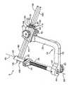
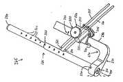
先ず、図1から図10を参照すると、膝関節の脛骨トンネルのような、骨トンネル内に少なくとも1つのクロスピン(図1から図10に図示せず)を配置するクロスピン案内組
立体5が図示されている。クロスピン案内組立体5は、基部分15及びアーム部分20を有するL字形部材10を備えている。アーム部分20は、基部分15に対し横方向に、好ましくは、基部分15に対し直角に伸びている。Referring first to FIGS. 1-10, there is illustrated a
クロスピン案内組立体5は、その第1の端部30に隣接して、正反対の長手方向に細長とされた通路35を形成し、その第2の端部40にて、L字形部材10の基部分15に解放可能に取り付け得る骨トンネル案内ロッド25を更に備えている。一好適実施例において、骨トンネル案内ロッド25は、ガイドワイヤー(図1から図10に図示せず)上に配置し得るようにその軸線65に沿ってカニューレ付きとされている(図1から図10参照)。骨トンネル案内ロッド25は、基部分15に形成された穴45内に止めねじ50によって保持することができる。この1つの代替的な実施の形態において、骨トンネル案内ロッド25は、基部分15に固定状態に接続することができる。 The
図1から図10を更に参照すると、第1の端部30と第2の端部40との間で可動要素55が骨トンネル案内ロッド25上に配置されている。可動要素55は、案内ロッド25上で動き回り、このため第1の端部30からの可動要素55の距離は選択的に調節することができる。可動要素55は、これら長手方向位置の任意の位置にて案内ロッド25に固着することもできる。本発明の一好適実施例において、可動要素55は、図1から図10に示したもののようなラチェット装置を使用して案内ロッド25に可動に固着することができる。 With further reference to FIGS. 1-10, a
本発明は、任意の型式のクロスピンにて具体化することができ、外科的方法にて使用されるクロスピンの型式と独立的である。好ましくは、吸収性のクロスピンが所定の外科的方法にて使用されるようにする。従って、吸収性クロスピンを使用する場合、及びかかる吸収性クロスピンを展開させるため好ましい装置を使用する場合について、ACLの再形態形成に関して以下に説明する。 The present invention can be embodied in any type of cross pin and is independent of the type of cross pin used in the surgical procedure. Preferably, an absorbable cross pin is used in a predetermined surgical method. Accordingly, the use of an absorbent cross pin and the use of a preferred device for deploying such an absorbent cross pin will be described below with respect to ACL reshape.
より具体的には、吸収性クロスピン255、260(図34)を使用する一好適実施例において、トロカールスリーブの案内部材58(図1から図10)は、L字形部材10のアーム部分20に取り外し可能に接続できる。トロカールスリーブの案内部材58には、貫通して伸びる穴60が形成されている。穴60は、骨トンネル案内ロッド25の長手方向軸線と直交している。従って、少なくとも1つのクロスピンは、脛骨トンネルを貫通し得るように最終的に脛骨内に配置される。より好ましくは、穴60は、患者の脛骨平部の真下にて骨トンネル案内ロッド25の長手方向軸線65と直交するような形態とされている。このようにして、少なくとも1つのクロスピンは、脛骨平部に隣接して且つ、最大の最強度領域にて脛骨の皮質骨内で展開されよう。止めねじ70を使用してトロカールスリーブの案内部材58をアーム部分20上の所要位置に解放可能に保持することができる。 More specifically, in one preferred embodiment using absorbent cross pins 255, 260 (FIG. 34), the trocar sleeve guide member 58 (FIGS. 1-10) is removed from the
これと代替的に、又はこれに加えて、アーム部分20には、トロカールスリーブの案内部材58がアーム部分20に沿って動くのを制限するためストッパ手段(図示せず)を設けることができる。トロカールスリーブの案内部材58は、止めねじ75により共に解放可能に保持された2つの半体にて形成され、これにより以下に更に説明するように、トロカールスリーブの案内部材58を穴60を貫通する第1及び第2のトロカールスリーブ80、85から分離させることができる。 Alternatively or additionally, the
第1及び第2のトロカールスリーブ80、85(図1から図10及び図11から図13)は、穴60によって摺動可能に受け入れられ(図1)、このため、スリーブ80、85は、穴60内で軸方向に且つ回転可能に動くことができる。トロカールスリーブ80、85の各々には、その内部に形成された対角状に伸びるスロット95を有するカラー部分90が設けられる。クロスピン案内組立体5は、また、スリーブ80、85内に配置するた
め1つ又は2つ以上のトロカール100を有することが好ましい(図1から図10、図11から図13)。トロカール100の各々には、骨に貫入するための鋭角な端部105が設けられている。横方向に伸びるピン110がトロカール100の他端付近であるが、該他端100から隔てられた位置に設けられている。ピン110は、所要位置に固定され且つトロカールスリーブ80、85のスロット95内に受け入れられ、このためトロカール100が軸方向(末端方向)に且つ回転動作すると、スリーブ80、85も同様の動作を行う。The first and
第1及び第2の吸収性ロッド255、266(図34参照)又は既知の材料から成るその他の型式のロッドは、以下に更に説明するように、スリーブ80、85を通じて摺動可能である。 First and second
別の好適実施例において、案内部材58は、トロカールスリーブ80、85及びトロカール100を使用せずに、クロスピンを直接配置し得るような形態とされている。この場合、クロスピンは、案内部材58の穴60の各々を通じて挿入し且つ該穴60の各々によって案内される。 In another preferred embodiment, the
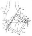
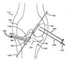
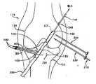
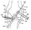
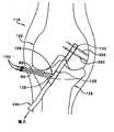
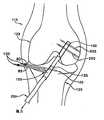
次に、図1を参照すると、大腿骨120及び脛骨125を有する、人間の膝関節115が図示されている。適宜な大腿骨トンネル130及び適宜な脛骨トンネル135が当該技術分野にて周知の手段及び方法によって設けられている。ガイドワイヤー140は、図示するように、トンネル130、135を貫通して伸びている。 Referring now to FIG. 1, a human knee joint 115 having a
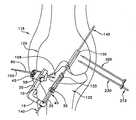
次に、図15を参照すると、大腿骨の交差状ピン止めラック組立体145又は別の同様の装置が設けられて、クロスピン255、260(図30)を大腿骨トンネル130を横断して配置する。ラック組立体145を使用して、カニューレ付きスリーブ155は、ガイドワイヤー140に装荷され、脛骨トンネル135を通り且つカニューレ付きスリーブの頭部分160(図15)が大腿骨トンネル130の環状肩部165に係合するまで、大腿骨トンネル130内を上方に伸びる。ガイドワイヤー140は、L字形部材180の基部分175に形成された穴170(図15)を貫通して伸びている。カニューレ付きスリーブの頭部分160は、大腿骨トンネル130内に密着嵌めし得るような寸法とされることが好ましい。カニューレ付きスリーブ155は、骨トンネル130、135内に配置し、次に、L字形部材180に接続するか、又は、より好ましくは、カニューレ付きスリーブ155を、最初に、L字形部材180に接続し、次に、大腿骨トンネル130及び脛骨トンネル135内に配置することができる。トロカールスリーブの案内部材185(図15)は、アーム部分190上で既に配置されていないならば、次に、止めねじ(図示せず)等によってアーム部分190に固定する。 Referring now to FIG. 15, a femoral cross pinning
次に、図16を参照すると、次に、第1のトロカールスリーブ200を案内部材185(図16)の穴205内に挿入し、トロカール210のピン215がスリーブ200のスロット220内に入れ子式に嵌まるまで、トロカール210がスリーブ200を通って伸び、トロカールの鋭利な先端225がスリーブ200の末端を超えて伸びるようにする。これと代替的に、トロカール200は、第1のトロカールスリーブ200が穴205内に取り付けられる前に、第1のトロカールスリーブ200内に取り付けることができる。いずれの場合でも、次に、トロカールスリーブ200及びトロカール210の組合せ体を1つのユニットとして大腿骨120内に穿孔し、カニューレ付きスリーブ155(図16)の拡大頭部分160に向かうが、その丁度手前で終わるようにする。 Referring now to FIG. 16, the
次に、トロカール210を第1のトロカールスリーブ200から引き出し、第2のトロカールスリーブ230(図17)内に配置することができる。これと代替的に、第2のトロカールスリーブ230に対し第2のトロカール210を設けてもよい。いずれの場合で
も、トロカールスリーブ230及びトロカール210の組合せ体は、次に、1つのユニットとして大腿骨120内に穿孔し、カニューレ付きスリーブ155(図17)の頭部分160に向かうが、丁度、その手前で終わるようにする。次に、ラックのL字形部材180を外科手術箇所から除去することができる。このことは、最初に、止めねじ(図示せず)を緩め、トロカールスリーブの案内部材185をその2つの半体に分離し、これによりトロカールスリーブ200、230が案内部材185から自由とされ、次に、カニューレ付きスリーブが骨トンネル130、135から出るまで、カニューレ付きスリーブ155をガイドワイヤー140に沿って下方に摺動させることにより行うことができる。この方法により、トロカールスリーブ200、230は大腿骨120(図18)内に止まったままである。The
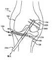
次に、図19を参照すると、骨トンネル案内ロッド25(図1から図10)はガイドワイヤー140上を供給され、案内ロッドの第1の端部30が脛骨平部235と整合するまで、脛骨トンネル135内に上方に進ませる。関節鏡240を使用して案内ロッドの第1の端部30が脛骨平部235と整合したときを判断することができる。 Referring now to FIG. 19, the bone tunnel guide rod 25 (FIGS. 1-10) is fed over the
次に、図20を参照すると、次に、可動要素55(図1から図10)を案内ロッド25に沿って案内ロッドの第1の端部30及び脛骨125に向けて移動させる。可動要素55が脛骨125に対して配置され(また、案内ロッドの第1の端部30が脛骨平部235に隣接して配置された)とき、可動要素55は、所要位置に係止され、このため、案内ロッド25は、脛骨トンネル135内に更に進むことができない。この形態において、案内組立体5は、末端方向に向けた力を案内ロッド25に加えることにより脛骨125に対して安定化させることができ、可動要素55は脛骨125に対する案内ロッドの位置を保つ。 Referring now to FIG. 20, the movable element 55 (FIGS. 1-10) is then moved along the
次に、図21を参照すると、骨トンネル案内ロッド25は、L字形部材10に接続され且つ、脛骨トンネル135内に配置された状態で示してある。1つの実施の形態において、骨トンネル案内ロッド25は、最初に、L字形部材10に接続し、次に、脛骨トンネル135内に配置することができる。これと代替的に、一好適実施例において、骨トンネル案内ロッド25を最初に、脛骨トンネル135内に配置し、次に、L字形部材10に接続する。いずれの場合でも、可動要素55は、骨トンネル案内ロッド25を脛骨125に対し適正に配置し、案内ロッドの第1の端部30が脛骨平部235と整合される。トロカールスリーブの案内部材58(図1から図10)は、アーム部分20上に既に配置されてないならば、次に、止めねじ50等によってアーム部分20に固定する(図1から図10)。案内組立体5は、次のような幾何学的形態を有する、すなわち骨トンネル案内ロッド25の第1の端部30が脛骨トンネル135内に配置され、可動要素55が脛骨125の正面と係合し、このため、クロスピン255、260(図34)は、脛骨内の所望の方位にて方向決めされ、また、より好ましくは、脛骨平部235(図34)の真下に配置された強力な皮質骨を通じて方向決めされるような幾何学的形態を有するようにする。 Referring now to FIG. 21, the bone
次に、図22を参照すると、第1のトロカールスリーブ80は、次に、案内部材58の穴60内に挿入され、トロカール100はスリーブ80を通じて伸び、トロカールの鋭角な端部105がスリーブ80の末端を超えて伸びるようにする。これと代替的に、トロカール100は、第1のトロカールスリーブ80が案内部材の穴60内に取り付けられる前に、第1のトロカールスリーブ80内に取り付けてもよい。そのいずれの場合でも、スリーブ80及びトロカール100の組合せ体を次に、1つのユニットとして脛骨125内に案内ロッドの通路35(図2)に向けるが、通路35の丁度、手前にて穿孔する。 Referring now to FIG. 22, the
次に、トロカール100を第1のトロカールスリーブ80から引き出し且つ、第2のトロカールスリーブ85内に配置する。これと代替的に、第2のトロカール100を第2のトロカールスリーブ85内に設けてもよい。そのいずれの場合でも、次に、トロカールス
リーブ85及びトロカール100の組合せ体を1つのユニットとして、案内ロッド(図24)に向けるが、案内ロッドの丁度、手前にて脛骨125に穿孔する。Next, the
次に、案内組立体のL字形部材10を外科手術箇所から取り外すことができる。このことは、最初に止めねじ75(図1から図10)を緩め、トロカールスリーブの案内部材58をその2つの半体に分離し、これにより80、85が案内部材58から自由にされ、次に、案内ロッド25が脛骨トンネル135から出るまで、骨トンネル案内ロッド25をガイドワイヤー140に沿って下方に摺動させることで行うことができる。この方法は、トロカールスリーブ80、85が脛骨125内で止まったままにする(図25)。 The L-shaped
重要なことは、案内組立体5の幾何学的形態のため、トロカールスリーブ80、85(従って、クロスピン255、260)は、脛骨平部235の真下に配置された強力な皮質骨内に挿入する。 Importantly, because of the geometry of the
次に、移植体靭帯250が大腿骨トンネル130の環状肩部165と係合する(図26)まで、ガイドワイヤー140を使用して移植体靭帯250(非限定的に、柔軟な移植体及び骨ブロック移植体を含む)に取り付けられた縫合糸245を脛骨トンネル135を通じて大腿骨トンネル130内に引き込む。ガイドワイヤー140には、この手順を容易にし得るようにその基端に隣接してアイレット(図示せず)を設ける。次に、大腿骨120の頂部から出る縫合糸245の部分に張力を維持することにより、移植体靭帯250をこの位置に保持することができる。 Next, the graft ligament 250 (including, but not limited to, a flexible graft and bone) is used using the
次に、第1のトロカールスリーブ200内に配置された第2のトロカールスリーブ230からトロカール210を取り外し、次に、スリーブ200及びトロカール210を図27に示すように、移植体靭帯250の末端に穿孔する。次に、第2のスリーブ230内に配置されたスリーブ200からトロカール210を取り外し、図27に示すように、第2のスリーブ230及びトロカール210を移植体靭帯250の末端に穿孔する。次に、トロカール210(又は、1つ以上のトロカールが使用される場合、トロカール210)をスリーブ200、230から引き出すことができる(図28)。次に、ロッド255をトロカールスリーブ200を通じて靭帯250を通って伸びる位置まで摺動させることにより、第1の吸収性ロッド255(図29)を展開させる。次に、スリーブ200を靭帯250及び大腿骨120から引き出し、第1の吸収性ロッド255が大腿骨120内の所要位置に残り且つ、靭帯250を通って伸びるままにする。同様に、第2の吸収性ロッド260をスリーブ230を通じて所要位置に摺動させることができる。次に、スリーブ230を取り外し、靭帯250を通って伸びる第1の吸収性ロッド255と共に、第2の吸収性ロッド260が残り、図29に示すように、靭帯250が大腿骨トンネル130内の所望位置に係止するようにする。 Next, the
次に、図30を参照すると、次に、脛骨125から出る靭帯250の基端部分に張力を維持することにより、移植体靭帯250を所要位置に保持することができる。
次に、移植体靭帯250を脛骨125に取り付ける。より具体的には、図31に示すように、第1のトロカールスリーブ80及びトロカール100を靭帯250に穿孔する。次に、第2のスリーブ85内に配置された第1のスリーブ80からトロカールを取り外し、第2のスリーブ85及びトロカール100を図32に示すように、靭帯250に穿孔する。これと代替的に、第2のスリーブ85と共に使用するため第2のトロカール100を設けてもよい。そのいずれの場合でも、トロカールスリーブ80、85が固定された後、次に、スリーブ80、85(図23)からトロカール100(又は、1つ以上のトロカールが使用されるならば、トロカール100)を引き出すことができる。次に、ロッド255をトロカールスリーブ80を通じて靭帯250を通って伸びる位置に摺動させることにより、第1の吸収性ロッド255を挿入する。次に、スリーブ80を靭帯250及び脛骨1
25から引き出し、第1の吸収性ロッド255が脛骨125内の所要位置に残り且つ靭帯250を通って伸びるようにする。同様に、次に、第2の吸収性ロッド260をスリーブ85を通って所要位置に摺動させる。次に、スリーブ85は、取り外し、靭帯250を通って伸びる第1の吸収性ロッド255と共に、第2の吸収性ロッド260が残り、図34に示すように、靭帯250が脛骨トンネル135内の所要位置に係止するようにする。Referring now to FIG. 30, the
Next, the
25 so that the first
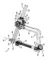
次に、図35から図38を参照すると、少なくとも1つのクロスピン(図35から図38に図示せず)を膝関節の脛骨トンネルのような骨トンネル内に配置するための骨トンネル基準ガイド265が図示されている。骨トンネル基準ガイド265は、この手順にて使用し、移植体靭帯(柔軟な組織移植体及び骨ブロック移植体の双方を含む)を骨トンネル内に固定することができる。骨トンネル基準ガイド265は、基部分275及びアーム部分280を有するL字形部材270を備えている。アーム部分280は、基部分275に対して横方向に且つ該基部分に対し直角に伸びている。 Referring now to FIGS. 35-38, there is a bone
骨トンネル基準ガイド265は、第1の端部290及び第2の端部295を有する骨トンネル案内ロッド285を更に備えている。骨トンネル案内ロッド285は、第1の端部290及び第2の端部295の間に目盛り付き割り出し部300を有している。骨トンネル案内ロッド285は、その長さの中間に、正反対の方向に伸びる長手方向に細長とされた通路305を有しており、第2の端部295にてL字形部材270の基部分275に接続されている。一好適実施例において、骨トンネル案内ロッド285は、ガイドワイヤー(図示せず)上に配置するため箇所306にてカニューレ付きとされている(図35)。骨トンネル案内ロッド285は、基部分275に形成された穴315内にピン320により保持することができる。 The bone
更に図35から図38を参照すると、L字形部材270のアーム部分280上に目盛り325が設けられている。目盛り325は、以下に説明するように、骨トンネル案内ロッド285上の目盛り付き割出し部300と調和させてある。 With further reference to FIGS. 35-38, a
本発明は。任意の型式のクロスピンにて具体化することができ、また、外科的方法で使用されるクロスピンの型式から独立的である。好ましくは、吸収性のクロスピンが所定の外科的方法にて使用されるものとする。従って、吸収性ピンを使用する場合、また、かかる吸収性ピンを展開させる場合に関して、以下にACL再形態形成について説明する。 The present invention. It can be embodied in any type of cross pin and is independent of the type of cross pin used in the surgical procedure. Preferably, an absorbable cross pin is used in a predetermined surgical method. Therefore, ACL reshape will be described below with respect to the use of absorbent pins and the deployment of such absorbent pins.
より具体的には、吸収性クロスピンを使用する一好適実施例において、トロカールスリーブ案内部材330は、L字形部材270のアーム部分280に取り外し可能に接続でき、また、該アーム部分280の目盛り325と共に選択的に調節可能である。トロカールスリーブの案内部材330には、貫通して伸びる穴335が設けられている。穴335は、骨トンネル案内ロッド285の長手方向軸線340を通って伸びている。従って、少なくとも1つのクロスピンは、脛骨トンネルを通り得るように最終的に脛骨内に配置されている。より好ましくは、穴335は、患者の脛骨平部の真下で骨トンネルガイド部285の長手方向軸線340と交差するような形態とされている。このようにして、少なくとも1つのクロスピンは、脛骨平部に隣接し且つ該平部の真下で、また、最大骨強度領域にて脛骨の皮質部分内に展開させる。止めねじ345を使用してトロカールスリーブの案内部材330をアーム部分280の目盛り325に沿って所要位置に解放可能に保持することができる。トロカールスリーブの案内部材330は、止めねじ350によって共に解放可能に保持された2つの半体に形成されることが好ましく、これにより、以下に説明するように、スリーブ案内部材330を、穴335を通って伸びる第1及び第2のトロカールスリーブ355、360から取り外すことができる。 More specifically, in one preferred embodiment using an absorbent cross pin, the trocar
別の好適実施例において、トロカールスリーブの案内部材330は、トロカールスリー
ブ355、360を使用せずに、クロスピンを直接配置し得る形態とされている。この場合、クロスピンは、案内部材330の穴335の各々に挿入され且つ穴335の各々によって案内される。In another preferred embodiment, the trocar
骨トンネル基準ガイド265は、次のようにして使用することが好ましい。最初に、大腿骨トンネル130及び脛骨トンネル135(図14)を形成する。次に、案内ロッド285の末端290が大腿骨トンネル130(図14)の末端と係合するまで、基準ガイドの案内ロッド285(図35から図38)を脛骨トンネル135及び大腿骨トンネル130を経て上方に進める。この状態となったとき、基準ガイドのL字形部材270は、患者の大腿骨の外方でトロカールスリーブの案内部材30を支持する。大腿骨トンネル130の末端165と係合した案内ロッド285に末端方向への力を加えることにより、骨トンネル基準ガイド265は安定化される。この安定化によってクロスピンを正確に配置することが可能となる。次に、案内ロッド285が脛骨平部を形成する時点にて目盛り付き割り出し部300を読み取るため、関節鏡を使用する。次に、トロカールスリーブの案内部材330をそれ自体の目盛り325に沿った相応する位置に固定する。この点に関して、目盛り付き割り出し部300は、目盛り325と調和されて、穴335(図35)、従ってクロスピンの軸線が脛骨平部の丁度、真下にて脛骨皮質骨を通るような、所望の位置にて脛骨を通るようにされることが理解されよう。 The bone
次に、ドリルスリーブ355、360を使用してトロカール365、370を脛骨内に固定する。次に、トロカールスリーブ案内部材330をその2つの半体に分離し、ドリルスリーブ355、360を基準ガイド265から自由にし、基準ガイド265を、例えば、該ガイドワイヤーから基端方向に引き出すことによって外科手術部位から除去する。次に、移植体靭帯を大腿骨トンネル130及び脛骨トンネル135内に上方に引張り、移植体靭帯の末端を大腿骨トンネル130内でしっかりと形成し、次に、ドリルスリーブ355、360を使用して移植体靭帯の末端を通じて吸収性クロスピンを固定し、これにより靭帯を脛骨に交差状にピン止めする。 Next, trocars 365 and 370 are secured in the tibia using
次に、図39を参照すると、図40に示したクロスピン案内組立体308のようなクロスピン案内組立体と共に使用される骨トンネル案内ロッド305のキット300が示してある。本発明の1つの好ましい形態において、クロスピン案内組立体308は、クロスピン案内部材5の骨トンネル案内ロッド25が図39に示した骨トンネル案内ロッド305の1つと置換されている点を除いて、図1から図10に示したクロスピン案内組立体5と同様である。 Referring now to FIG. 39, a
骨トンネル案内ロッド305の各々は、基端310及び末端315を有している。骨トンネル内への挿入を制限する挿入制限手段320は、基端310と末端315との間に配置されている。好ましくは、挿入制限手段320は、所定の骨トンネル案内ロッド305の末端321と基端322との間の中間に形成された環状肩部を備えるようにする。 Each bone
挿入制限手段320は、骨トンネル案内ロッド305の末端321から所定の距離325に配置されている。キット300の各々は、少なくとも2つの骨トンネル案内ロッドを備えており、トンネル案内ロッドの各々の所定の距離325は互いに相違する。従って、少なくとも1つの骨トンネル案内ロッド305を骨トンネル内に挿入し且つ挿入制限手段320が患者の脛骨の前側と係合したとき、その末端321が患者の脛骨平部と整合した骨トンネル案内ロッド305の1つを選ぶことにより、キット300からの選択が行われる。この構造の結果、選ばれた骨トンネルロッド305がクロスピン案内組立体308内に装荷されたとき、穴60(図40)、従ってクロスピンは、脛骨平部の真下にて厚い皮質骨に配置され、これにより、脛骨の交差状ピン止めを確実に且つ高信頼状態で行うことを可能にする。 The
本発明は、本明細書に開示され及び(又は)図面に示したその特定の適用例にのみ何ら限定されるものではないことを理解すべきである。例えば、説明の目的のため、本発明は人間の膝関節に関して説明し且つ図示した。本明細書に記載した方法及び装置は、かかる適用に関して特に有益であることが理解される。しかし、当該技術分野の当業者には、本明細書に記載した方法及び装置は哺乳類一般に有用であり、また、例えば、肩関節等のようなその他の骨に関しても有用であることが予想されよう。 It should be understood that the invention is not limited in any way to that specific application disclosed herein and / or shown in the drawings. For example, for purposes of explanation, the present invention has been described and illustrated with respect to a human knee joint. It will be appreciated that the methods and apparatus described herein are particularly beneficial for such applications. However, one of ordinary skill in the art would expect that the methods and devices described herein will be useful for mammals in general and also for other bones such as, for example, shoulder joints and the like. .
更に、トロカール100、210は、本明細書にて骨に侵入する鋭利な先端を有する硬いロッドの形態として開示されている。従って、例えば、トロカール100、210は、三角錐形の前側点を有するガイドワイヤー又はKワイヤーを備えることも可能である。しかし、これと代替的に、本発明は、捩れドリル、スペードドリル及び(又は)他の何らかの種類のドリルを備えるトロカール100、210にて具体化することも考えられる。 Further, the
トロカール100及び(又は)210は、その関係した案内部材58、ラック組立体145、基準ガイド265、案内組立体308及び(又は)装置400と共に使用して、吸収性ロッド255、260を固定するが、その関係したスリーブ80、85、200、230はそれぞれ使用しないことが考えられる。この場合、少なくとも1つのトロカールは、少なくとも1つの吸収性ロッド255、260が骨ブロック内に配置されるまで、常に移植体靭帯250内に配置される。
所望であるならば、1つのスリーブ80、1つのトロカール100又は1つのスリーブ85及び1つのトロカール100又は1つのスリーブ200及び1つのトロカール210のみを使用し且つ、スリーブ及び(又は)トロカールを全く使用せずに本発明を実施することも可能である。 If desired, use only one
Claims (41)
Translated fromJapanese基端及び末端を有する骨トンネル案内ロッドと、
骨トンネル案内ロッドの周りで摺動可能に配置された可動要素であって、上記末端と該可動要素との間で上記案内ロッドの長さを選択的に調節し得る位置に係止可能である前記可動要素と、
基部分及びアーム部分を有し、該基部分が前記骨トンネル案内ロッドの前記基端に隣接して取り付け可能であるフレーム部材と、
該フレーム部材の前記アーム部分に接続されたドリル案内部材と、
少なくとも1つのクロスピン穴を前記骨に且つ前記骨トンネルを横断して穿孔する穿孔手段とを備え、該穿孔手段が前記ドリル案内部材によって所要位置に支持され、前記ドリル案内部材が前記フレーム部材に取り付けられ、前記フレーム部材が前記骨トンネル案内ロッドに取り付けられ、前記骨トンネル案内ロッドが前記骨トンネル内に挿入され、該装置が前記骨に対して保持され、前記可動要素が前記骨トンネル内への更なる挿入を制限するようにした、装置。In an apparatus for positioning at least one cross pin in a bone through a bone tunnel,
A bone tunnel guide rod having a proximal end and a distal end;
A movable element slidably disposed around a bone tunnel guide rod, and lockable in a position where the length of the guide rod can be selectively adjusted between the distal end and the movable element The movable element;
A frame member having a base portion and an arm portion, the base portion being attachable adjacent to the proximal end of the bone tunnel guide rod;
A drill guide member connected to the arm portion of the frame member;
Drilling means for drilling at least one cross pin hole in the bone and across the bone tunnel, the drilling means being supported in place by the drill guide member, the drill guide member being attached to the frame member The frame member is attached to the bone tunnel guide rod, the bone tunnel guide rod is inserted into the bone tunnel, the device is held against the bone, and the movable element is moved into the bone tunnel. A device designed to limit further insertion.
に解放可能に保持する止めねじを更に備える、装置。The apparatus of claim 1, further comprising a set screw that releasably holds the drill guide member on the arm portion of the frame member.
第1の開放端及び第2の開放端を備え、該第1の開放端と前記第2の開放端との間の部分が靭帯を受け入れ得る寸法とされた直径を有する、骨トンネルを骨に形成するステップと、
基端及び末端を有する案内ロッドを前記骨トンネル内に挿入するステップと、
前記案内ロッドの前記末端を前記骨トンネルの前記第2の開放端に隣接して位置決めするステップと、
可動要素を前記骨トンネルの第1の開放端部にて骨に対して前記案内ロッド上で位置決めするステップと、
ドリル案内部材によって所要位置に支持された穿孔手段であって、前記ドリル案内部材がフレーム部材に取り付けられ、前記フレーム部材が前記骨トンネル案内ロッドに取り付けられ、前記骨トンネル案内ロッドが前記骨トンネル内に挿入され、前記可動要素が骨トンネル案内ロッドの前記骨トンネル内への更なる挿入を制限する、前記穿孔手段を使用して少なくとも1つのクロスピン穴を前記骨を通じて且つ前記骨トンネルを横断して横方向に穿孔するステップと、
少なくとも1つのクロスピンを前記少なくとも1つのクロスピン穴を通じて挿入するステップとを備える、方法。In the method of fixing the ligament in the bone tunnel,
A bone tunnel comprising a first open end and a second open end, the portion between the first open end and the second open end having a diameter sized to receive a ligament Forming step;
Inserting a guide rod having a proximal end and a distal end into the bone tunnel;
Positioning the distal end of the guide rod adjacent to the second open end of the bone tunnel;
Positioning a movable element on the guide rod relative to the bone at a first open end of the bone tunnel;
Drilling means supported at a required position by a drill guide member, wherein the drill guide member is attached to a frame member, the frame member is attached to the bone tunnel guide rod, and the bone tunnel guide rod is inserted into the bone tunnel. And the movable element restricts further insertion of a bone tunnel guide rod into the bone tunnel, using the drilling means to pass at least one cross pin hole through the bone and across the bone tunnel. Drilling laterally; and
Inserting at least one cross pin through the at least one cross pin hole.
基端及び末端を有し、前記基端及び前記末端の間に目盛り付き割出し部を有する前記骨トンネル案内ロッドであって、前記目盛り付き割出し部が少なくとも1つのクロスピン穴の所期の位置に対し前記骨トンネル内部の所定の位置にて読み取られるようにした、前記骨トンネル案内ロッドと、
基部分及びアーム部分を有するフレーム部材であって、該基部分が前記骨トンネル案内ロッドの前記基端に隣接して取り付け可能であり、前記フレーム部材の前記アーム部分が前記骨トンネル案内ロッドの前記目盛り付き割出し部と相応する目盛りを有する、前記フレーム部材と、
前記フレーム部材の前記アーム部分に取り付け可能なドリル案内部材であって、前記フレーム部材の前記目盛りに対し選択的に調節可能な前記ドリル案内部材と、
前記少なくとも1つのクロスピン穴を前記骨トンネルを通じて前記骨に穿孔する穿孔手段であって、前記ドリル案内部材により所要位置に支持された前記穿孔手段とを備え、前記ドリル案内部材が、前記フレーム部材に取り付けられ、前記フレーム部材が、前記骨トンネル案内ロッドに取り付けられ、前記骨トンネル案内ロッドが骨トンネル内に挿入され、装置の前記末端が、前記骨トンネルの前記終端に対し保持され、前記骨トンネル内への
更なる挿入を制限するようにした、装置。In an apparatus for positioning at least one cross pin in a bone through a bone tunnel,
The bone tunnel guide rod having a proximal end and a distal end, and having a graduated index portion between the proximal end and the distal end, wherein the graduated index portion is an intended position of at least one cross pin hole The bone tunnel guide rod is adapted to be read at a predetermined position inside the bone tunnel,
A frame member having a base portion and an arm portion, the base portion being attachable adjacent to the proximal end of the bone tunnel guide rod, wherein the arm portion of the frame member is the portion of the bone tunnel guide rod; The frame member having a scale corresponding to the indexed portion with a scale;
A drill guide member attachable to the arm portion of the frame member, the drill guide member selectively adjustable with respect to the scale of the frame member;
Drilling means for drilling the at least one cross pin hole in the bone through the bone tunnel, the drilling means supported at a required position by the drill guide member, and the drill guide member on the frame member Attached, the frame member is attached to the bone tunnel guide rod, the bone tunnel guide rod is inserted into the bone tunnel, and the distal end of the device is held against the end of the bone tunnel; A device designed to limit further insertion into it.
第1の部分及び第2の部分を備え、該第1の部分が第1の開放端部及び第2の開放端部を有し、該第2の部分が第3の開放端部及び第4の終端部を有し、前記第1の開放端部と前記第4の終端部との間の部分が前記靭帯を受け入れ得る寸法とされた骨トンネルを骨に形成するステップと、
基端及び末端を有し、基端及び末端の間に目盛り付き割出し部を有する骨トンネル案内ロッドを骨トンネル内に挿入するステップと、
前記案内ロッドの前記末端を前記骨トンネルの第4の終端に対して位置決めするステップと、
前記骨トンネルの前記第2の開放端部に対する前記目盛り付き割出し部の位置を決定するステップと、
フレーム部材であって、前記骨トンネル案内ロッドの前記目盛り付き割出し部に相応する目盛りを有する前記フレーム部材に取り付けられたドリルガイドを位置決めし、該ドリルガイドが前記骨トンネルのドリルの開放端部に対して目盛り付き割出し部に従って目盛りに対して位置決めされるようにするステップと、
クロスピン穴を穿孔する穿孔手段であって、前記ドリル案内部材により所要位置に支持され、前記ドリル案内部材がフレーム部材に取り付けられた前記穿孔手段を使用して少なくとも1つのクロスピン穴を前記骨を通って横方向に前記骨トンネル内に穿孔するステップであって、前記フレーム部材が前記骨トンネル案内ロッドに取り付けられ、前記骨トンネル案内ロッドが前記骨トンネル内に挿入され、前記骨トンネルの前記第4の終端が骨トンネル内への更なる挿入を制限するようにした前記ステップと、
少なくとも1つのクロスピンを前記クロスピン穴を通じて挿入するステップとを備える、方法。In the method of fixing the ligament in the bone tunnel,
A first portion and a second portion, the first portion having a first open end and a second open end, the second portion being a third open end and a fourth; Forming a bone tunnel in the bone with a portion of the first open end and a portion between the first open end and the fourth end sized to receive the ligament;
Inserting a bone tunnel guide rod having a proximal end and a distal end and having a graduated index between the proximal end and the distal end into the bone tunnel;
Positioning the end of the guide rod relative to a fourth end of the bone tunnel;
Determining the position of the graduated index relative to the second open end of the bone tunnel;
Positioning a drill guide attached to the frame member having a scale corresponding to the indexed portion of the bone tunnel guide rod, the drill guide being an open end of the bone tunnel drill To be positioned relative to the scale according to the indexed portion with respect to
A drilling means for drilling a cross pin hole, wherein the drill guide member supports the drill pin in a desired position, and the drill guide member is attached to a frame member, so that at least one cross pin hole is passed through the bone. Drilling laterally into the bone tunnel, wherein the frame member is attached to the bone tunnel guide rod, the bone tunnel guide rod is inserted into the bone tunnel, and the fourth of the bone tunnel. Said step in which the end of the tube restricts further insertion into the bone tunnel;
Inserting at least one cross pin through the cross pin hole.
骨トンネル案内ロッドであって、各々が基端及び末端を有し、各々が前記骨トンネル内への挿入を制限する挿入制限手段を有する前記骨トンネル案内ロッドのキットを備え、前記骨トンネル案内ロッドの各々の前記挿入制限手段が、その末端から所定の距離に配置され、該キットが、少なくとも2つの骨トンネル案内ロッドを備え、前記骨トンネル案内ロッドの各々の前記所定の距離が互いに相違し、前記骨トンネル案内ロッドの少なくとも1つを前記骨トンネル内に挿入し且つ、前記挿入制限手段が別の骨表面と係合しているとき、その末端が骨表面と整合した骨トンネル案内ロッドを選ぶことにより、前記キットからの選択が行われ、
基部分及びアーム部分を有するフレーム部材であって、該基部分が前記選ばれた骨トンネル案内ロッドの前記基端に隣接して取り付け可能である前記フレーム部材と、
前記フレーム部材の前記アーム部分に取り付けられたドリル案内部材と、
前記骨トンネルを通じて前記骨に前記少なくとも1つのクロスピン穴を穿孔する穿孔手段であって、前記ドリル案内部材によって所要位置に支持され、前記ドリル案内部材が前記フレーム部材に取り付けられ、前記フレーム部材が前記選ばれた骨トンネル案内ロッドに取り付けられ、前記選ばれた骨トンネル案内ロッドが前記骨トンネル内に挿入される前記穿孔手段と、
前記骨トンネル内への更なる挿入を防止する前記挿入制限手段とを備える、位置決め装置。In an apparatus for positioning at least one cross pin in a hole through a bone tunnel,
A bone tunnel guide rod comprising a kit of bone tunnel guide rods, each having a proximal end and a distal end, each having an insertion restriction means for restricting insertion into the bone tunnel; Each of the insertion restriction means is disposed at a predetermined distance from its distal end, and the kit comprises at least two bone tunnel guide rods, the predetermined distances of each of the bone tunnel guide rods being different from each other; When at least one of the bone tunnel guide rods is inserted into the bone tunnel and the insertion limiting means is engaged with another bone surface, a bone tunnel guide rod whose distal end is aligned with the bone surface is selected. The selection from the kit is made,
A frame member having a base portion and an arm portion, the base portion being attachable adjacent to the proximal end of the selected bone tunnel guide rod;
A drill guide member attached to the arm portion of the frame member;
Drilling means for drilling the at least one cross pin hole in the bone through the bone tunnel, supported by the drill guide member at a required position, the drill guide member being attached to the frame member, and the frame member being The piercing means attached to a selected bone tunnel guide rod, the selected bone tunnel guide rod being inserted into the bone tunnel;
And a positioning device for preventing further insertion into the bone tunnel.
第1の開放端部及び第2の開放端部を有し、前記第1の開放端部と前記第2の開放端部との間の一部分が靭帯を受け入れ得る寸法とされた直径を有する骨トンネルを骨に形成するステップと、
骨トンネル案内ロッドであって、各々が基端及び末端を有し、前記骨トンネル内への挿
入を制限する挿入制限手段を有し、前記骨トンネル案内ロッドの各々の挿入制限手段がその末端から所定の距離に配置された前記骨トンネル案内ロッドのキットからのすくなくとも1つの案内ロッドを骨トンネル内に挿入するステップであって、該キットは、少なくとも2つの骨トンネル案内ロッドを有し、前記骨トンネル案内ロッドの各々の前記所定の距離が互いに相違するようにする前記ステップと、
骨トンネル案内ロッドの少なくとも1つを骨トンネル内に挿入し且つ、前記挿入制限手段が骨トンネルの第1の端部に隣接して骨と係合するとき、その末端が前記骨トンネルの前記第2の端部と整合した骨トンネル案内ロッドを選ぶステップと、
ドリル案内部材により所定位置に支持され、クロスピン穴を穿孔する穿孔手段を使用して前記骨を貫通し且つ、前記骨トンネルを横断して横方向に少なくとも1つのクロスピン穴を穿孔するステップであって、前記フレーム部材が前記選ばれた骨トンネル案内ロッドに取り付けられ、前記選んだ骨トンネル案内ロッドが骨トンネル内に挿入され、骨トンネル案内ロッドの前記骨トンネル内への更なる挿入を制限する前記挿入制限手段を備えるようにする前記ステップと、
少なくとも1つのクロスピンを前記少なくとも1つのクロスピン穴を通じて挿入するステップとを備える、靭帯を骨トンネル内で固定する方法。In the method of fixing the ligament in the bone tunnel,
A bone having a first open end and a second open end, and having a diameter dimensioned to receive a ligament, a portion between the first open end and the second open end. Forming a tunnel in the bone;
A bone tunnel guide rod, each having a proximal end and a distal end, with insertion restriction means for restricting insertion into the bone tunnel, wherein each insertion restriction means of the bone tunnel guide rod is from its distal end. Inserting at least one guide rod from the bone tunnel guide rod kit disposed at a predetermined distance into the bone tunnel, the kit comprising at least two bone tunnel guide rods; The step of causing the predetermined distance of each of the tunnel guide rods to be different from each other;
When at least one of the bone tunnel guide rods is inserted into the bone tunnel and the insertion limiting means engages the bone adjacent to the first end of the bone tunnel, its distal end is the first of the bone tunnel. Selecting a bone tunnel guide rod aligned with the ends of the two;
Drilling at least one cross-pin hole transversely across the bone tunnel using a drilling means supported in place by a drill guide member and drilling the cross-pin hole. The frame member is attached to the selected bone tunnel guide rod, and the selected bone tunnel guide rod is inserted into the bone tunnel to limit further insertion of the bone tunnel guide rod into the bone tunnel. The step of providing insertion limiting means;
Inserting at least one cross-pin through the at least one cross-pin hole and securing the ligament in the bone tunnel.
Applications Claiming Priority (4)
| Application Number | Priority Date | Filing Date | Title |
|---|---|---|---|
| US27543101P | 2001-03-13 | 2001-03-13 | |
| US60/275,431 | 2001-03-13 | ||
| US09/865,274 | 2001-05-25 | ||
| US09/865,274US6517546B2 (en) | 2001-03-13 | 2001-05-25 | Method and apparatus for fixing a graft in a bone tunnel |
Related Parent Applications (1)
| Application Number | Title | Priority Date | Filing Date |
|---|---|---|---|
| JP2002570919ADivisionJP4195298B2 (en) | 2001-03-13 | 2002-03-13 | Method and apparatus for securing an implant in a bone tunnel |
Related Child Applications (1)
| Application Number | Title | Priority Date | Filing Date |
|---|---|---|---|
| JP2010249707ADivisionJP5080631B2 (en) | 2001-03-13 | 2010-11-08 | Method and apparatus for securing an implant in a bone tunnel |
Publications (2)
| Publication Number | Publication Date |
|---|---|
| JP2009006152Atrue JP2009006152A (en) | 2009-01-15 |
| JP4754605B2 JP4754605B2 (en) | 2011-08-24 |
Family
ID=26957414
Family Applications (3)
| Application Number | Title | Priority Date | Filing Date |
|---|---|---|---|
| JP2002570919AExpired - LifetimeJP4195298B2 (en) | 2001-03-13 | 2002-03-13 | Method and apparatus for securing an implant in a bone tunnel |
| JP2008181244AExpired - LifetimeJP4754605B2 (en) | 2001-03-13 | 2008-07-11 | Method and apparatus for securing an implant in a bone tunnel |
| JP2010249707AExpired - LifetimeJP5080631B2 (en) | 2001-03-13 | 2010-11-08 | Method and apparatus for securing an implant in a bone tunnel |
Family Applications Before (1)
| Application Number | Title | Priority Date | Filing Date |
|---|---|---|---|
| JP2002570919AExpired - LifetimeJP4195298B2 (en) | 2001-03-13 | 2002-03-13 | Method and apparatus for securing an implant in a bone tunnel |
Family Applications After (1)
| Application Number | Title | Priority Date | Filing Date |
|---|---|---|---|
| JP2010249707AExpired - LifetimeJP5080631B2 (en) | 2001-03-13 | 2010-11-08 | Method and apparatus for securing an implant in a bone tunnel |
Country Status (7)
| Country | Link |
|---|---|
| US (5) | US6517546B2 (en) |
| EP (1) | EP1377226B1 (en) |
| JP (3) | JP4195298B2 (en) |
| AU (2) | AU2002247337B2 (en) |
| CA (1) | CA2441050C (en) |
| DE (1) | DE60223348T2 (en) |
| WO (1) | WO2002071958A1 (en) |
Cited By (2)
| Publication number | Priority date | Publication date | Assignee | Title |
|---|---|---|---|---|
| JP2013043093A (en)* | 2011-08-24 | 2013-03-04 | Depuy Mitek Llc | Cross pinning guide device and method |
| KR101244901B1 (en)* | 2010-12-06 | 2013-03-18 | 김정재 | aiming arm for locking feumr medullary nail |
Families Citing this family (101)
| Publication number | Priority date | Publication date | Assignee | Title |
|---|---|---|---|---|
| US6066173A (en)* | 1998-01-28 | 2000-05-23 | Ethicon, Inc. | Method and apparatus for fixing a graft in a bone tunnel |
| US6878166B2 (en)* | 2000-08-28 | 2005-04-12 | Ron Clark | Method and implant for securing ligament replacement into the knee |
| US7530999B2 (en)* | 2000-08-28 | 2009-05-12 | Biomet Sports Medicine, Llc | Method and implant for securing ligament replacement into the knee |
| US7195642B2 (en)* | 2001-03-13 | 2007-03-27 | Mckernan Daniel J | Method and apparatus for fixing a graft in a bone tunnel |
| US6517546B2 (en)* | 2001-03-13 | 2003-02-11 | Gregory R. Whittaker | Method and apparatus for fixing a graft in a bone tunnel |
| US7594917B2 (en)* | 2001-03-13 | 2009-09-29 | Ethicon, Inc. | Method and apparatus for fixing a graft in a bone tunnel |
| US9463058B2 (en) | 2013-12-05 | 2016-10-11 | Acumed Llc | Guide for surgical wires, method, system, and device |
| US7175633B2 (en)* | 2001-10-17 | 2007-02-13 | Synthes (Usa) | Orthopedic implant insertion instruments |
| US7713300B2 (en)* | 2002-01-31 | 2010-05-11 | Biomet Sports Medicince, LLC | Apparatus and method for manipulating a flexible strand and soft tissue replacement during surgery |
| US20060206206A1 (en) | 2003-06-06 | 2006-09-14 | Peyman Gholam A | Intraocular telescope |
| US7033364B1 (en)* | 2002-01-31 | 2006-04-25 | Arthrotek, Inc. | Apparatus and method for manipulating a flexible strand and soft tissue replacement during surgery |
| US7270666B2 (en)* | 2002-05-15 | 2007-09-18 | Linvatec Corporation | Cross-pin graft fixation, instruments, and methods |
| US7175632B2 (en)* | 2002-05-15 | 2007-02-13 | Linvatec Corporation | Cross-pin graft fixation instruments and method |
| US7338492B2 (en)* | 2002-05-15 | 2008-03-04 | Linvatec Corporation | Cross-pin graft fixation, instruments, and methods |
| US9468449B2 (en) | 2010-12-02 | 2016-10-18 | Smith & Nephew, Inc. | Reconstructive joint tunnel drilling locator |
| AU2003902467A0 (en)* | 2003-05-19 | 2003-06-05 | Boris Rjazancev | A prosthetic component, a method of attaching a prosthetic component to a bone, a method of performing knee replacement surgery and a frame for application to a knee joint during knee replacement surgery |
| US7300439B2 (en)* | 2003-06-24 | 2007-11-27 | Depuy Mitek, Inc. | Porous resorbable graft fixation pin |
| US7491206B2 (en)* | 2003-06-27 | 2009-02-17 | Ethicon, Inc. | Adjustable drill guide assembly and method of use |
| US7896917B2 (en)* | 2003-10-15 | 2011-03-01 | Biomet Sports Medicine, Llc | Method and apparatus for graft fixation |
| US7341592B1 (en)* | 2003-10-15 | 2008-03-11 | Biomet Sports Medicine, Inc. | Method and apparatus for graft fixation |
| GR20040100020A (en)* | 2004-01-20 | 2005-09-27 | Ηρακλης Ιωαννη Πατσοπουλος | System of tools for the arthroscopic reconstruction of both segements of the cruciate ligament |
| US8088128B2 (en) | 2004-03-25 | 2012-01-03 | Depuy Mitek, Inc. | Implantable cross-pin for anterior cruciate ligament repair |
| AU2005253927B2 (en)* | 2004-04-22 | 2010-11-25 | Covidien Lp | Apparatus and method for reconstructing a ligament |
| US20070239166A1 (en)* | 2004-05-11 | 2007-10-11 | Mcguire David A | Surgical Device for Anterolateral and Posterolateral Reconstruction |
| US20050261701A1 (en)* | 2004-05-11 | 2005-11-24 | Mcguire David A | Surgical device for a anterolateral reconstruction |
| US7033363B2 (en)* | 2004-05-19 | 2006-04-25 | Sean Powell | Snap-lock for drill sleeve |
| US7294133B2 (en)* | 2004-06-03 | 2007-11-13 | Zimmer Technology, Inc. | Method and apparatus for preparing a glenoid surface |
| US8002778B1 (en) | 2004-06-28 | 2011-08-23 | Biomet Sports Medicine, Llc | Crosspin and method for inserting the same during soft ligament repair |
| US7776672B2 (en)* | 2004-08-19 | 2010-08-17 | Fuji Electric Systems Co., Ltd. | Semiconductor device and manufacturing method thereof |
| JP4982948B2 (en)* | 2004-08-19 | 2012-07-25 | 富士電機株式会社 | Manufacturing method of semiconductor device |
| US7458975B2 (en)* | 2004-12-21 | 2008-12-02 | Johnson & Johnson | Method of replacing an anterior cruciate ligament in the knee |
| US7527648B2 (en)* | 2004-12-21 | 2009-05-05 | Mitek Surgical Products Div Of Ethicon, Inc. | Method of replacing an anterior cruciate ligament in the knee |
| US7833244B2 (en) | 2005-04-20 | 2010-11-16 | Arthroscopic Innovations Llc | Suture fixation device and method for surgical repair |
| CA2605288C (en)* | 2005-04-20 | 2014-09-30 | Arthroscopic Innovations Llc | Method and apparatus for surgical repair |
| US20070100346A1 (en)* | 2005-10-27 | 2007-05-03 | Wyss Joseph G | Support for locating instrument guides |
| ATE481039T1 (en) | 2005-11-10 | 2010-10-15 | Arthrex Inc | DEVICE FOR RESTORING THE ANTERIOR CRUCIAL LIGAMENT USING A DRILL FOR RETROGRADE SHAPING OF CANALS |
| US9770344B2 (en)* | 2006-03-23 | 2017-09-26 | Imperial Innovations Ltd. | Reconstruction of anterior cruciate ligaments |
| US7942914B2 (en)* | 2006-10-17 | 2011-05-17 | Arthroscopic Innovations Llc | Method and apparatus for surgical repair |
| EP2120788B1 (en) | 2007-01-25 | 2013-11-27 | Arthrex, Inc. | Drill pin for fixation of ligaments using button/loop construct |
| US8147546B2 (en) | 2007-03-13 | 2012-04-03 | Biomet Sports Medicine, Llc | Method and apparatus for graft fixation |
| US8632568B2 (en) | 2007-09-24 | 2014-01-21 | Stryker Corporation | Suture anchor having a suture engaging structure and inserter arrangement |
| US8187281B2 (en)* | 2007-10-10 | 2012-05-29 | Ebi, Llc | Variable angle targeting device |
| DE102007057075A1 (en) | 2007-11-23 | 2009-05-28 | Karl Storz Gmbh & Co. Kg | Tibial target device for the dual channel technique |
| US9826992B2 (en) | 2007-12-21 | 2017-11-28 | Smith & Nephew, Inc. | Multiple portal guide |
| US8956278B2 (en) | 2007-12-21 | 2015-02-17 | Smith & Nephew, Inc. | Multiple portal guide |
| US8298239B2 (en)* | 2008-02-21 | 2012-10-30 | Tyco Healthcare Group Lp | Tibial guide for ACL repair having interchangeable and/or rotatable outrigger |
| US8323289B2 (en)* | 2008-02-21 | 2012-12-04 | Covidien Lp | Tibial guide for ACL repair having left/right docking configuration |
| US20100049198A1 (en)* | 2008-02-21 | 2010-02-25 | Tyco Healthcare Group Lp | Tibial guide for acl repair having off-axis guide wire arrangement |
| US20100049199A1 (en)* | 2008-02-21 | 2010-02-25 | Tyco Healthcare Group Lp | Tibial guide for acl repair having moveable distal features |
| AU2009200864A1 (en)* | 2008-02-29 | 2009-09-17 | Robert J. Medoff | Method and apparatus for articular scapholunate reconstruction |
| JP5964545B2 (en) | 2008-03-04 | 2016-08-03 | スミス アンド ネフュー インコーポレーテッドSmith & Nephew,Inc. | Apparatus and method for use in ligament regenerative surgery |
| AU2009222580B2 (en)* | 2008-10-10 | 2014-11-27 | Depuy Mitek, Inc. | Method for replacing a ligament in a knee |
| US8740911B2 (en)* | 2008-11-07 | 2014-06-03 | Howmedica Osteonics Corp. | Method of preparing a femur for implantation of a femoral implant |
| US20100121375A1 (en)* | 2008-11-13 | 2010-05-13 | Pandya Rajiv D | Suture anchoring system and method |
| US8932301B2 (en)* | 2009-08-26 | 2015-01-13 | Biomet C.V. | Targeting jig for hip fracture nail system |
| GB0918006D0 (en)* | 2009-10-14 | 2009-12-02 | Chana Gursharan S | Improvements in or relating to the removal of articles embedded in surrounding material |
| US8821504B2 (en) | 2009-11-20 | 2014-09-02 | Zimmer Knee Creations, Inc. | Method for treating joint pain and associated instruments |
| JP2013511356A (en)* | 2009-11-20 | 2013-04-04 | ニー・クリエイションズ・リミテッド・ライアビリティ・カンパニー | Device for variable angle approach to joints |
| US8579900B2 (en)* | 2010-01-06 | 2013-11-12 | Chia-Hao Hsu | Minimally invasive skeletal fixation device |
| EP2547279A1 (en) | 2010-03-18 | 2013-01-23 | Smith&Nephew, Inc. | A device for use during ligament reconstruction surgery |
| DE102010024259B4 (en)* | 2010-06-18 | 2012-12-13 | Richard Wolf Gmbh | Surgical target device for cruciate ligament reconstruction |
| MX2013003496A (en) | 2010-09-27 | 2013-12-02 | Smith & Nephew Inc | Device and methods for use during arthroscopic surgery. |
| WO2012061639A1 (en) | 2010-11-03 | 2012-05-10 | Smith & Nephew, Inc. | Drill guide |
| US8685033B2 (en)* | 2011-06-27 | 2014-04-01 | Smith & Nephew, Inc. | Anatomic femoral guide |
| US20130123809A1 (en) | 2011-11-11 | 2013-05-16 | VentureMD Innovations, LLC | Transosseous attachment instruments |
| US10675014B2 (en) | 2011-11-16 | 2020-06-09 | Crossroads Extremity Systems, Llc | Knotless soft tissue attachment |
| US10548585B2 (en) | 2011-11-16 | 2020-02-04 | VentureMD Innovations, LLC | Soft tissue attachment |
| US10470756B2 (en) | 2011-11-16 | 2019-11-12 | VentureMD Innovations, LLC | Suture anchor and method |
| US10136883B2 (en) | 2011-11-16 | 2018-11-27 | VentureMD Innovations, LLC | Method of anchoring a suture |
| ES2656974T3 (en)* | 2012-01-19 | 2018-03-01 | Stryker European Holdings I, Llc | Cuff for suprarrotulian surgery |
| US9186163B2 (en) | 2012-06-04 | 2015-11-17 | Depuy Mitek, Llc | Methods and devices for forming bone tunnels |
| US9687221B2 (en) | 2013-02-13 | 2017-06-27 | Venture MD Innovations, LLC | Method of anchoring a suture |
| US9386997B2 (en) | 2013-03-29 | 2016-07-12 | Smith & Nephew, Inc. | Tunnel gage |
| WO2014179802A2 (en)* | 2013-05-03 | 2014-11-06 | The Curators Of The University Of Missouri | Systems and methods for alignment and site preparation of rotator cuff grafts |
| US10045789B2 (en) | 2014-09-30 | 2018-08-14 | Medos International Sàrl | Universal surgical guide systems and methods |
| US10307173B2 (en) | 2014-09-30 | 2019-06-04 | Medos International Sàrl | Gage for limiting distal travel of drill pin |
| US10010333B2 (en) | 2014-09-30 | 2018-07-03 | Medos International Sàrl | Side-loading carriage for use in surgical guide |
| US10098646B2 (en) | 2014-09-30 | 2018-10-16 | Medos International Sàrl | Surgical guide for use in ligament repair procedures |
| GB201507116D0 (en)* | 2015-04-27 | 2015-06-10 | Alam Mohammed I | A new approach for interconnecting fractured femoral bone segments |
| US10258401B2 (en) | 2015-07-17 | 2019-04-16 | Kator, Llc | Transosseous guide |
| US10820918B2 (en) | 2015-07-17 | 2020-11-03 | Crossroads Extremity Systems, Llc | Transosseous guide and method |
| US9962174B2 (en) | 2015-07-17 | 2018-05-08 | Kator, Llc | Transosseous method |
| US10386950B2 (en)* | 2015-07-22 | 2019-08-20 | Sharp Kabushiki Kaisha | Touch-panel-equipped display device and method for manufacturing touch-panel-equipped display device |
| US10226243B2 (en) | 2015-08-04 | 2019-03-12 | Kator, Llc | Transosseous suture anchor |
| US12383253B2 (en) | 2015-08-04 | 2025-08-12 | Crossroads Extremity Systems, Llc | Suture anchor |
| US10064632B2 (en) | 2016-02-19 | 2018-09-04 | Rajiv D. Pandya | System and technique for accessing extra articular lesions or abnormalities or intra osseous lesions or bone marrow lesions |
| US9925010B2 (en) | 2016-02-19 | 2018-03-27 | Rajiv D. Pandya | System and technique for accessing extra articular lesions or abnormalities or intra osseous lesions or bone marrow lesions |
| US11419684B2 (en) | 2016-02-19 | 2022-08-23 | Rajiv D. Pandya | System and technique for accessing extra articular lesions or abnormalities or intra osseous lesions or bone marrow lesions |
| US11376079B2 (en) | 2016-02-19 | 2022-07-05 | Rajiv D. Pandya | System and technique for accessing extra articular lesions or abnormalities or intra osseous lesions or bone marrow lesions |
| CN209851112U (en)* | 2017-10-16 | 2019-12-27 | 创科(澳门离岸商业服务)有限公司 | Angled hole fixture |
| EP3583905A1 (en) | 2018-06-20 | 2019-12-25 | Arthrex Inc | Percutaneous targeting device |
| IT201800009919A1 (en) | 2018-10-30 | 2020-04-30 | La Marzocco Srl | Active water monitoring and filtration system for an espresso coffee machine and its espresso coffee machine |
| IT201900001623A1 (en) | 2019-02-05 | 2020-08-05 | La Marzocco Srl | Coffee grinder machine with improved dosing system and relative method |
| US11357517B1 (en) | 2019-04-25 | 2022-06-14 | Nirav H. Amin | System and method for creating graft tunnels in bone |
| WO2021211249A1 (en)* | 2020-04-13 | 2021-10-21 | Wright Medical Technology, Inc. | Alignment devices for use in correction of bone deformities |
| CN112155707B (en)* | 2020-10-29 | 2022-11-01 | 江佩师 | Femoral tunnel guiding and positioning device for reconstruction of anterior cruciate ligament |
| US20240050243A1 (en)* | 2020-12-23 | 2024-02-15 | Formae, Inc. | Instruments and methods for preparing patient recipient site and installing medical implant |
| ES2921907A1 (en)* | 2021-02-22 | 2022-09-02 | Univ Granada | DEVICE FOR THE SUPPORT AND GUIDANCE OF RIGID ELEMENTS IN THE CONSOLIDATION OF THE FRACTURE OF THE SCAPHHOID BONE |
| US11963688B2 (en) | 2021-11-20 | 2024-04-23 | Panorthopaedics, Inc. | Device adapted for lateral engagement of an elongated member |
| US20250017719A1 (en)* | 2023-07-12 | 2025-01-16 | Integrity Medical Services Inc. | Tissue repair devices, systems, and methods |
| US12433583B1 (en) | 2024-05-31 | 2025-10-07 | Integrity Medical Services Inc. | Suture passer devices, systems, and methods |
Citations (5)
| Publication number | Priority date | Publication date | Assignee | Title |
|---|---|---|---|---|
| JPH0257247A (en)* | 1987-10-21 | 1990-02-27 | Jellicoe Enterp Pty Ltd | Surgical equipment |
| JPH08505550A (en)* | 1993-01-15 | 1996-06-18 | デピュイ インコーポレイテッド | Drill guide device and method |
| JPH10505516A (en)* | 1994-07-28 | 1998-06-02 | デピュイ オーソピーディック,インコーポレイテッド | Replacement ligament graft through and method |
| WO1998035621A1 (en)* | 1997-02-13 | 1998-08-20 | Mednext Inc. | Adjustable depth drill guide |
| JPH11267135A (en)* | 1998-01-28 | 1999-10-05 | Ethicon Inc | Method and apparatus for fixing transplant in tunnel of bone |
Family Cites Families (147)
| Publication number | Priority date | Publication date | Assignee | Title |
|---|---|---|---|---|
| US422706A (en)* | 1890-03-04 | Chili mill | ||
| US2112337A (en)* | 1936-06-06 | 1938-03-29 | Gillespie Percy Joseph | Means for drawing-off slivers in combing machines, gill boxes, or other machines for preparing textile fibers for spinning |
| GB1465744A (en) | 1974-01-30 | 1977-03-02 | Ethicon Inc | Attaching fibrous connective tissue to bone |
| IL46030A0 (en) | 1974-11-11 | 1975-02-10 | Rosenberg L | Orthopaedic screw |
| US4022191A (en) | 1976-06-04 | 1977-05-10 | Khosrow Jamshidi | Biopsy needle guard and guide |
| US4257411A (en) | 1979-02-08 | 1981-03-24 | Cho Kenneth O | Cruciate ligament surgical drill guide |
| GB2084468B (en) | 1980-09-25 | 1984-06-06 | South African Inventions | Surgical implant |
| DE8208970U1 (en)* | 1982-03-30 | 1982-09-09 | Howmedica International, Inc. Zweigniederlassung Kiel, 2301 Schönkirchen | Distal aiming device for an interlocking nail |
| JPS591966U (en) | 1982-06-26 | 1984-01-07 | 杉村 宣行 | Backup spring for packing hydraulic equipment |
| US4462395A (en) | 1983-03-02 | 1984-07-31 | Johnson Lanny L | Arthroscopic ligamentous and capsular fixation system |
| FR2560764B1 (en) | 1984-03-09 | 1988-05-13 | Matco | DAVIER FOR FRACTURE REDUCTION |
| EP0209685A3 (en) | 1985-07-12 | 1988-11-09 | Fischerwerke Arthur Fischer GmbH & Co. KG | Fixation element for osteosynthesis |
| US4792336A (en) | 1986-03-03 | 1988-12-20 | American Cyanamid Company | Flat braided ligament or tendon implant device having texturized yarns |
| FR2598311B1 (en) | 1986-05-07 | 1988-09-09 | Laboureau Jacques | SURGICAL INSTRUMENT FOR FOCUSING AND PLACING THE PLASTY (OR PROSTHETIC REPLACEMENT) OF THE LIGAMENT CROSS POSTERIOR KNEE |
| US4838282A (en)* | 1987-02-26 | 1989-06-13 | Manan Manufacturing Co., Inc. | Bone biopsy needle assembly |
| US4898156A (en) | 1987-05-18 | 1990-02-06 | Mitek Surgical Products, Inc. | Suture anchor |
| US4809694A (en) | 1987-05-19 | 1989-03-07 | Ferrara Vincent L | Biopsy guide |
| US4809594A (en)* | 1987-08-11 | 1989-03-07 | Bloomfield Industries, Inc. | Tea brewer |
| US4968315A (en) | 1987-12-15 | 1990-11-06 | Mitek Surgical Products, Inc. | Suture anchor and suture anchor installation tool |
| US4899743A (en) | 1987-12-15 | 1990-02-13 | Mitek Surgical Products, Inc. | Suture anchor installation tool |
| US5080673A (en) | 1988-02-03 | 1992-01-14 | Intermedics Orthopedics, Inc. | Glenoid prosthesis and method of use |
| DE3811345C1 (en) | 1988-04-02 | 1989-09-07 | Aesculap Ag, 7200 Tuttlingen, De | |
| US4858603A (en) | 1988-06-06 | 1989-08-22 | Johnson & Johnson Orthopaedics, Inc. | Bone pin |
| US4944742A (en) | 1988-06-06 | 1990-07-31 | Johnson & Johnson Orthopaedics, Inc. | Bone pin |
| US4901711A (en) | 1988-12-27 | 1990-02-20 | Marlowe Goble E | Drill guide |
| US4950270A (en) | 1989-02-03 | 1990-08-21 | Boehringer Mannheim Corporation | Cannulated self-tapping bone screw |
| US5522817A (en) | 1989-03-31 | 1996-06-04 | United States Surgical Corporation | Absorbable surgical fastener with bone penetrating elements |
| US5067962A (en) | 1989-04-18 | 1991-11-26 | Baxter International Inc. | Bioprosthetic ligament |
| US4986833A (en) | 1989-05-05 | 1991-01-22 | Worland Richard L | Glenoid component for an artificial shoulder joint |
| DE3936703A1 (en) | 1989-11-03 | 1991-05-08 | Lutz Biedermann | BONE SCREW |
| US5004474A (en) | 1989-11-28 | 1991-04-02 | Baxter International Inc. | Prosthetic anterior cruciate ligament design |
| EP0437174B1 (en) | 1990-01-08 | 1993-12-22 | SULZER Medizinaltechnik AG | Artificial ligament and/or tendon replacement implant |
| US5053042A (en) | 1990-01-16 | 1991-10-01 | Bidwell Clifford D | Biopsy needle guide for use with CT scanner |
| US5031634A (en) | 1990-01-19 | 1991-07-16 | Beth Israel Hospital Assoc., Inc. | Adjustable biopsy needle-guide device |
| US4985032A (en) | 1990-05-14 | 1991-01-15 | Marlowe Goble E | Drill guide |
| US5120318A (en) | 1990-06-25 | 1992-06-09 | Harinathareddy Nallapareddy | Arthroscopy portal maker |
| US5100387A (en) | 1990-07-02 | 1992-03-31 | Ng Raymond C | Disposable universal needle guide apparatus (for amniocentesis) |
| US5013318A (en)* | 1990-07-31 | 1991-05-07 | Special Devices Incorporated | Medical instrument for measuring depth of fastener hold in bone |
| US5385567A (en)* | 1990-09-07 | 1995-01-31 | Goble; E. Marlowe | Sight barrel arthroscopic instrument |
| US5098435A (en) | 1990-11-21 | 1992-03-24 | Alphatec Manufacturing Inc. | Cannula |
| US5108446A (en) | 1990-11-26 | 1992-04-28 | Sulzer Brothers Limited | Hip joint prosthesis |
| US5314487A (en) | 1991-02-14 | 1994-05-24 | Smith & Nephew Richards Inc. | Acetabular prosthesis with anchoring pegs |
| US5235987A (en) | 1991-02-22 | 1993-08-17 | Dymax Corporation | Needle guide |
| CA2062012C (en) | 1991-03-05 | 2003-04-29 | Randall D. Ross | Bioabsorbable interference bone fixation screw |
| US5147362A (en) | 1991-04-08 | 1992-09-15 | Marlowe Goble E | Endosteal ligament fixation device |
| US5201742A (en) | 1991-04-16 | 1993-04-13 | Hasson Harrith M | Support jig for a surgical instrument |
| FR2676356A1 (en) | 1991-05-13 | 1992-11-20 | Cendis Medical | Fixation element for ligaments |
| US5279309A (en) | 1991-06-13 | 1994-01-18 | International Business Machines Corporation | Signaling device and method for monitoring positions in a surgical operation |
| US5298012A (en) | 1991-09-30 | 1994-03-29 | Baxter International Inc. | Tendon graft preparation workstation |
| US5681320A (en)* | 1991-12-13 | 1997-10-28 | Mcguire; David A. | Bone-cutting guide |
| US5672158A (en) | 1992-01-07 | 1997-09-30 | Sherwood Medical Company | Catheter introducer |
| US5316014A (en) | 1992-02-07 | 1994-05-31 | Livingston Products, Inc. | Biopsy locator and guide |
| US5320111A (en) | 1992-02-07 | 1994-06-14 | Livingston Products, Inc. | Light beam locator and guide for a biopsy needle |
| AU672596B2 (en) | 1992-02-14 | 1996-10-10 | Smith & Nephew, Inc. | Polymeric screws and coatings for surgical uses |
| US5154720A (en) | 1992-02-19 | 1992-10-13 | Linvatec Corporation | Surgical drill guide |
| US5562664A (en) | 1992-02-20 | 1996-10-08 | Arthrex Inc. | Drill guide with target PCL-oriented marking hook |
| US5152764A (en) | 1992-05-18 | 1992-10-06 | Marlowe Goble E | Femoral tunnel entry drill guide |
| US5312409A (en)* | 1992-06-01 | 1994-05-17 | Mclaughlin Robert E | Drill alignment guide |
| US5234434A (en) | 1992-08-17 | 1993-08-10 | Marlowe Goble E | Mutliple guide sleeve drill guide |
| US5257632A (en)* | 1992-09-09 | 1993-11-02 | Symbiosis Corporation | Coaxial bone marrow biopsy coring and aspirating needle assembly and method of use thereof |
| US5266075A (en) | 1992-10-05 | 1993-11-30 | Roy Clark | Tendon threader for endosteal ligament mounting |
| ATE161703T1 (en) | 1992-11-02 | 1998-01-15 | Sulzer Orthopaedie Ag | ANCHORAGE FOR AN ARTIFICIAL LIGAMENT, ESPECIALLY A CRUCIAL LIGAMENT OF A KNEE JOINT |
| US5397356A (en) | 1993-01-15 | 1995-03-14 | Depuy Inc. | Pin for securing a replacement ligament to a bone |
| US5354300A (en)* | 1993-01-15 | 1994-10-11 | Depuy Inc. | Drill guide apparatus for installing a transverse pin |
| US5431651A (en) | 1993-02-08 | 1995-07-11 | Goble; E. Marlowe | Cross pin and set screw femoral and tibial fixation method |
| US5372599A (en) | 1993-03-12 | 1994-12-13 | Mitek Surgical Products, Inc. | Surgical anchor and method for deploying the same |
| US5356413A (en) | 1993-03-12 | 1994-10-18 | Mitek Surgical Products, Inc. | Surgical anchor and method for deploying the same |
| JP3180219B2 (en)* | 1993-07-09 | 2001-06-25 | ニプロ株式会社 | Trocar |
| US5494039A (en) | 1993-07-16 | 1996-02-27 | Cryomedical Sciences, Inc. | Biopsy needle insertion guide and method of use in prostate cryosurgery |
| IL107523A (en) | 1993-11-07 | 2000-01-31 | Ultraguide Ltd | Articulated needle guide for ultrasound imaging and method of using same |
| JP2616684B2 (en)* | 1993-12-28 | 1997-06-04 | 日本電気株式会社 | Decoder circuit |
| US5538509A (en)* | 1994-01-31 | 1996-07-23 | Richard-Allan Medical Industries, Inc. | Trocar assembly |
| FR2716364B1 (en)* | 1994-02-22 | 1996-05-15 | Rahuaud Jacques | Viewfinder for anterior knee ligamentoplasty. |
| US5829444A (en) | 1994-09-15 | 1998-11-03 | Visualization Technology, Inc. | Position tracking and imaging system for use in medical applications |
| DE69531994T2 (en) | 1994-09-15 | 2004-07-22 | OEC Medical Systems, Inc., Boston | SYSTEM FOR POSITION DETECTION BY MEANS OF A REFERENCE UNIT ATTACHED TO A PATIENT'S HEAD FOR USE IN THE MEDICAL AREA |
| US5954670A (en) | 1994-10-05 | 1999-09-21 | Baker; Gary H. | Mandrel-guided tandem multiple channel biopsy guide device and method of use |
| ATE228338T1 (en) | 1994-10-07 | 2002-12-15 | Univ St Louis | SURGICAL NAVIGATION ARRANGEMENT INCLUDING REFERENCE AND LOCATION SYSTEMS |
| US5674224A (en) | 1994-11-18 | 1997-10-07 | Howell; Stephen M. | Bone mulch screw assembly for endosteal fixation of soft tissue grafts and method for using same |
| US5601562A (en) | 1995-02-14 | 1997-02-11 | Arthrex, Inc. | Forked insertion tool and metnod of arthroscopic surgery using the same |
| DE19510372C1 (en)* | 1995-03-22 | 1996-07-25 | Aesculap Ag | Drilling gauge for surgical drilling instruments with sleeve |
| US5868673A (en) | 1995-03-28 | 1999-02-09 | Sonometrics Corporation | System for carrying out surgery, biopsy and ablation of a tumor or other physical anomaly |
| KR19990029038A (en) | 1995-07-16 | 1999-04-15 | 요아브 빨띠에리 | Free aiming of needle ceramic |
| FR2741796B1 (en) | 1995-11-30 | 1998-03-27 | Tornier Sa | DEVICE FOR FIXING A PROSTHESIS AND PARTICULARLY A GLENOIDAL PROSTHESIS OF OMOPLATE |
| US5697933A (en) | 1995-12-18 | 1997-12-16 | Medicinelodge, Inc. | Bone-tendon-bone drill guide |
| IT1285549B1 (en) | 1996-01-26 | 1998-06-18 | Alberto Bauer | TISSUE COLLECTION SYSTEM (BIOPSY) USING A BIOPSY NEEDLE APPLIANCE AND A TESO A GETTING STARTED GUIDE |
| US5919193A (en) | 1996-03-14 | 1999-07-06 | Slavitt; Jerome A. | Method and kit for surgically correcting malformations in digits of a finger or toe |
| US5669885A (en) | 1996-05-14 | 1997-09-23 | United States Surgical Corporation | Trocar assembly with spring-loaded mechanism |
| JPH1050306A (en)* | 1996-07-31 | 1998-02-20 | Toyota Autom Loom Works Ltd | Manufacture of hydrogen storage alloy electrode |
| US5688284A (en)* | 1996-09-20 | 1997-11-18 | Medicinelodge, Inc. | Variable angle drill guide and ligament fixation method |
| US5984930A (en) | 1996-09-30 | 1999-11-16 | George S. Allen | Biopsy guide |
| US5766250A (en) | 1996-10-28 | 1998-06-16 | Medicinelodge, Inc. | Ligament fixator for a ligament anchor system |
| FR2755846B1 (en) | 1996-11-20 | 1998-12-31 | Jacques Philippe Laboureau | PRE-ORIENT PROSTHETIC LIGAMENT AND METHOD OF MAKING |
| US5891150A (en)* | 1996-12-04 | 1999-04-06 | Chan; Kwan-Ho | Apparatus and method for fixing a ligament in a bone tunnel |
| US5849013A (en) | 1997-01-14 | 1998-12-15 | Whittaker; Gregory R. | Method and apparatus for fixing a bone block in a bone tunnel |
| US5918604A (en) | 1997-02-12 | 1999-07-06 | Arthrex, Inc. | Method of loading tendons into the knee |
| CA2280882C (en) | 1997-02-14 | 2003-12-30 | At&T Corp. | Video objects coded by keyregions |
| US6400979B1 (en) | 1997-02-20 | 2002-06-04 | Johns Hopkins University | Friction transmission with axial loading and a radiolucent surgical needle driver |
| US6731966B1 (en) | 1997-03-04 | 2004-05-04 | Zachary S. Spigelman | Systems and methods for targeting a lesion |
| US5766179A (en) | 1997-03-05 | 1998-06-16 | Orthofix S.R.L. | Mechanical system for blind nail-hole alignment of bone screws |
| US5911707A (en) | 1997-04-09 | 1999-06-15 | Datascope Investment Corp. | Needle guide |
| USD422706S (en) | 1997-04-30 | 2000-04-11 | Surgical Navigation Technologies | Biopsy guide tube |
| US6231565B1 (en) | 1997-06-18 | 2001-05-15 | United States Surgical Corporation | Robotic arm DLUs for performing surgical tasks |
| US5957947A (en) | 1997-07-18 | 1999-09-28 | Wattiez; Arnaud | Single use trocar assembly |
| US6280472B1 (en) | 1997-07-23 | 2001-08-28 | Arthrotek, Inc. | Apparatus and method for tibial fixation of soft tissue |
| WO1999015095A1 (en) | 1997-09-24 | 1999-04-01 | Depuy Orthopaedics, Inc. | Acl fixation pin and method |
| US6030364A (en) | 1997-10-03 | 2000-02-29 | Boston Scientific Corporation | Apparatus and method for percutaneous placement of gastro-intestinal tubes |
| US6048321A (en) | 1997-10-10 | 2000-04-11 | William E. McPherson | Guide assembly for a biopsy device |
| US5941889A (en) | 1997-10-14 | 1999-08-24 | Civco Medical Instruments Inc. | Multiple angle disposable needle guide system |
| US6231585B1 (en) | 1997-11-20 | 2001-05-15 | Medivas, Llc | Device for stabilizing a treatment site and method of use |
| US5968050A (en)* | 1997-12-05 | 1999-10-19 | Smith & Nephew, Inc. | Positioning a tibial tunnel |
| US6283942B1 (en) | 1997-12-30 | 2001-09-04 | Volunteers For Medical Engineering | Needle insertion guide apparatus and method |
| US6066173A (en) | 1998-01-28 | 2000-05-23 | Ethicon, Inc. | Method and apparatus for fixing a graft in a bone tunnel |
| US6228061B1 (en)* | 1998-02-03 | 2001-05-08 | Imagyn Medical Technologies California, Inc. | Trocar seal system having dual seals |
| ATE274844T1 (en)* | 1998-04-09 | 2004-09-15 | Sdgi Holdings Inc | VERTEBRATE BODY DISTRACTOR |
| US6529765B1 (en) | 1998-04-21 | 2003-03-04 | Neutar L.L.C. | Instrumented and actuated guidance fixture for sterotactic surgery |
| US6355066B1 (en)* | 1998-08-19 | 2002-03-12 | Andrew C. Kim | Anterior cruciate ligament reconstruction hamstring tendon fixation system |
| US6361499B1 (en) | 1998-09-16 | 2002-03-26 | Civco Medical Instruments Inc. | Multiple angle needle guide |
| US6379307B1 (en) | 1998-09-16 | 2002-04-30 | Roy Filly | Adjustable needle guide apparatus and method |
| US6203499B1 (en) | 1998-10-05 | 2001-03-20 | Atl Ultrasound Inc. | Multiple angle needle guide |
| US6195577B1 (en) | 1998-10-08 | 2001-02-27 | Regents Of The University Of Minnesota | Method and apparatus for positioning a device in a body |
| AU1525400A (en) | 1998-11-18 | 2000-06-05 | Microdexterity Systems, Inc. | Medical manipulator for use with an imaging device |
| JP4542710B2 (en) | 1998-11-23 | 2010-09-15 | マイクロデクステラティー・システムズ・インコーポレーテッド | Surgical manipulator |
| US20020165611A1 (en) | 1998-12-22 | 2002-11-07 | Robert-Jan Enzerink | Graft material convenience package |
| US6501981B1 (en) | 1999-03-16 | 2002-12-31 | Accuray, Inc. | Apparatus and method for compensating for respiratory and patient motions during treatment |
| US6096060A (en) | 1999-05-20 | 2000-08-01 | Linvatec Corporation | Bioabsorbable threaded soft tissue anchor system |
| US6436119B1 (en) | 1999-09-30 | 2002-08-20 | Raymedica, Inc. | Adjustable surgical dilator |
| US6254606B1 (en)* | 1999-10-13 | 2001-07-03 | William P. Carney | Laser aiming device for performing anterior cruciate ligament reconstruction surgery and method for using same |
| US6575919B1 (en)* | 1999-10-19 | 2003-06-10 | Kyphon Inc. | Hand-held instruments that access interior body regions |
| US6245028B1 (en) | 1999-11-24 | 2001-06-12 | Marconi Medical Systems, Inc. | Needle biopsy system |
| US6342056B1 (en)* | 2000-02-04 | 2002-01-29 | Jean-Marc Mac-Thiong | Surgical drill guide and method for using the same |
| US6475152B1 (en) | 2000-03-13 | 2002-11-05 | Koninklijke Philips Electronics N.V. | Biopsy needle guide for attachment to an ultrasound transducer |
| US6535756B1 (en) | 2000-04-07 | 2003-03-18 | Surgical Navigation Technologies, Inc. | Trajectory storage apparatus and method for surgical navigation system |
| DE10049270B4 (en) | 2000-09-28 | 2005-09-15 | Richard Wolf Gmbh | Apparatus for conditioning a band to be implanted |
| US6468226B1 (en) | 2000-11-22 | 2002-10-22 | Mcintyre, Iv John J. | Remote tissue biopsy apparatus and associated methods |
| NO315143B1 (en) | 2000-11-24 | 2003-07-21 | Neorad As | Apparatus for light beam-guided biopsy |
| US6770076B2 (en) | 2001-02-12 | 2004-08-03 | Opus Medical, Inc. | Method and apparatus for attaching connective tissues to bone using a knotless suture anchoring device |
| US6517546B2 (en) | 2001-03-13 | 2003-02-11 | Gregory R. Whittaker | Method and apparatus for fixing a graft in a bone tunnel |
| US7195642B2 (en) | 2001-03-13 | 2007-03-27 | Mckernan Daniel J | Method and apparatus for fixing a graft in a bone tunnel |
| US7594917B2 (en) | 2001-03-13 | 2009-09-29 | Ethicon, Inc. | Method and apparatus for fixing a graft in a bone tunnel |
| US6783524B2 (en) | 2001-04-19 | 2004-08-31 | Intuitive Surgical, Inc. | Robotic surgical tool with ultrasound cauterizing and cutting instrument |
| US6770027B2 (en) | 2001-10-05 | 2004-08-03 | Scimed Life Systems, Inc. | Robotic endoscope with wireless interface |
| WO2003032837A1 (en) | 2001-10-12 | 2003-04-24 | University Of Florida | Computer controlled guidance of a biopsy needle |
| US6785572B2 (en) | 2001-11-21 | 2004-08-31 | Koninklijke Philips Electronics, N.V. | Tactile feedback and display in a CT image guided robotic system for interventional procedures |
| DE60112591T2 (en) | 2001-11-23 | 2006-05-18 | Nucletron B.V. | Automatic image-controlled device for introducing a cannula into a human or animal body for radiotherapy in this body |
| AU2003214837B2 (en) | 2002-02-06 | 2008-06-12 | The Johns Hopkins University | Remote center of motion robotic system and method |
| US6902526B2 (en) | 2002-10-23 | 2005-06-07 | Orthopaedic Development, Llc | Visualizing ablation device and procedure |
| US6902067B1 (en)* | 2003-03-07 | 2005-06-07 | Henry H. Barnes, Jr. | In-shell nut sorting and debris removal assembly |
- 2001
- 2001-05-25USUS09/865,274patent/US6517546B2/ennot_activeExpired - Lifetime
- 2002
- 2002-03-13WOPCT/US2002/007810patent/WO2002071958A1/enactiveIP Right Grant
- 2002-03-13DEDE60223348Tpatent/DE60223348T2/ennot_activeExpired - Lifetime
- 2002-03-13EPEP02715120Apatent/EP1377226B1/ennot_activeExpired - Lifetime
- 2002-03-13CACA2441050Apatent/CA2441050C/ennot_activeExpired - Fee Related
- 2002-03-13AUAU2002247337Apatent/AU2002247337B2/ennot_activeCeased
- 2002-03-13JPJP2002570919Apatent/JP4195298B2/ennot_activeExpired - Lifetime
- 2003
- 2003-02-11USUS10/364,786patent/US6958067B2/ennot_activeExpired - Lifetime
- 2005
- 2005-03-23USUS11/088,250patent/US7655011B2/ennot_activeExpired - Lifetime
- 2006
- 2006-09-08AUAU2006100762Apatent/AU2006100762A4/ennot_activeExpired
- 2008
- 2008-07-11JPJP2008181244Apatent/JP4754605B2/ennot_activeExpired - Lifetime
- 2009
- 2009-10-09USUS12/576,749patent/US8128634B2/ennot_activeExpired - Fee Related
- 2009-12-04USUS12/631,429patent/US8137360B2/ennot_activeExpired - Fee Related
- 2010
- 2010-11-08JPJP2010249707Apatent/JP5080631B2/ennot_activeExpired - Lifetime
Patent Citations (5)
| Publication number | Priority date | Publication date | Assignee | Title |
|---|---|---|---|---|
| JPH0257247A (en)* | 1987-10-21 | 1990-02-27 | Jellicoe Enterp Pty Ltd | Surgical equipment |
| JPH08505550A (en)* | 1993-01-15 | 1996-06-18 | デピュイ インコーポレイテッド | Drill guide device and method |
| JPH10505516A (en)* | 1994-07-28 | 1998-06-02 | デピュイ オーソピーディック,インコーポレイテッド | Replacement ligament graft through and method |
| WO1998035621A1 (en)* | 1997-02-13 | 1998-08-20 | Mednext Inc. | Adjustable depth drill guide |
| JPH11267135A (en)* | 1998-01-28 | 1999-10-05 | Ethicon Inc | Method and apparatus for fixing transplant in tunnel of bone |
Cited By (2)
| Publication number | Priority date | Publication date | Assignee | Title |
|---|---|---|---|---|
| KR101244901B1 (en)* | 2010-12-06 | 2013-03-18 | 김정재 | aiming arm for locking feumr medullary nail |
| JP2013043093A (en)* | 2011-08-24 | 2013-03-04 | Depuy Mitek Llc | Cross pinning guide device and method |
Also Published As
| Publication number | Publication date |
|---|---|
| JP5080631B2 (en) | 2012-11-21 |
| EP1377226A1 (en) | 2004-01-07 |
| CA2441050A1 (en) | 2002-09-19 |
| US8128634B2 (en) | 2012-03-06 |
| US6517546B2 (en) | 2003-02-11 |
| EP1377226A4 (en) | 2005-06-15 |
| DE60223348D1 (en) | 2007-12-20 |
| JP2005500089A (en) | 2005-01-06 |
| EP1377226B1 (en) | 2007-11-07 |
| US8137360B2 (en) | 2012-03-20 |
| JP4754605B2 (en) | 2011-08-24 |
| US20030130666A1 (en) | 2003-07-10 |
| US7655011B2 (en) | 2010-02-02 |
| WO2002071958A1 (en) | 2002-09-19 |
| US20020133165A1 (en) | 2002-09-19 |
| US20100121339A1 (en) | 2010-05-13 |
| CA2441050C (en) | 2011-07-19 |
| DE60223348T2 (en) | 2008-09-11 |
| US20100030222A1 (en) | 2010-02-04 |
| US20050234469A1 (en) | 2005-10-20 |
| JP4195298B2 (en) | 2008-12-10 |
| AU2006100762A4 (en) | 2006-10-05 |
| AU2002247337B2 (en) | 2006-06-08 |
| JP2011067639A (en) | 2011-04-07 |
| US6958067B2 (en) | 2005-10-25 |
Similar Documents
| Publication | Publication Date | Title |
|---|---|---|
| JP4754605B2 (en) | Method and apparatus for securing an implant in a bone tunnel | |
| JP4740537B2 (en) | Method and apparatus for securing a graft to a bone tunnel | |
| US8080013B2 (en) | Method and apparatus for fixing a graft in a bone tunnel | |
| JP4124824B2 (en) | Method and apparatus for fixing a bone block within a bone hole | |
| AU2002359297A1 (en) | Method and apparatus for fixing a graft in a bone tunnel | |
| AU2002247337A1 (en) | Method and apparatus for fixing a graft in a bone tunnel | |
| AU2007231608A1 (en) | Methods and devices for ligament repair | |
| US7491206B2 (en) | Adjustable drill guide assembly and method of use |
Legal Events
| Date | Code | Title | Description |
|---|---|---|---|
| A131 | Notification of reasons for refusal | Free format text:JAPANESE INTERMEDIATE CODE: A131 Effective date:20100708 | |
| A977 | Report on retrieval | Free format text:JAPANESE INTERMEDIATE CODE: A971007 Effective date:20100708 | |
| A601 | Written request for extension of time | Free format text:JAPANESE INTERMEDIATE CODE: A601 Effective date:20101007 | |
| A602 | Written permission of extension of time | Free format text:JAPANESE INTERMEDIATE CODE: A602 Effective date:20101013 | |
| A521 | Request for written amendment filed | Free format text:JAPANESE INTERMEDIATE CODE: A523 Effective date:20101029 | |
| TRDD | Decision of grant or rejection written | ||
| A01 | Written decision to grant a patent or to grant a registration (utility model) | Free format text:JAPANESE INTERMEDIATE CODE: A01 Effective date:20110426 | |
| A61 | First payment of annual fees (during grant procedure) | Free format text:JAPANESE INTERMEDIATE CODE: A61 Effective date:20110525 | |
| FPAY | Renewal fee payment (event date is renewal date of database) | Free format text:PAYMENT UNTIL: 20140603 Year of fee payment:3 | |
| R150 | Certificate of patent or registration of utility model | Ref document number:4754605 Country of ref document:JP Free format text:JAPANESE INTERMEDIATE CODE: R150 Free format text:JAPANESE INTERMEDIATE CODE: R150 | |
| R250 | Receipt of annual fees | Free format text:JAPANESE INTERMEDIATE CODE: R250 | |
| R250 | Receipt of annual fees | Free format text:JAPANESE INTERMEDIATE CODE: R250 | |
| R250 | Receipt of annual fees | Free format text:JAPANESE INTERMEDIATE CODE: R250 | |
| R250 | Receipt of annual fees | Free format text:JAPANESE INTERMEDIATE CODE: R250 | |
| R250 | Receipt of annual fees | Free format text:JAPANESE INTERMEDIATE CODE: R250 | |
| R250 | Receipt of annual fees | Free format text:JAPANESE INTERMEDIATE CODE: R250 | |
| R250 | Receipt of annual fees | Free format text:JAPANESE INTERMEDIATE CODE: R250 | |
| R250 | Receipt of annual fees | Free format text:JAPANESE INTERMEDIATE CODE: R250 | |
| EXPY | Cancellation because of completion of term |