JP2009004893A - Image processor and imaging system equipped with same - Google Patents
Image processor and imaging system equipped with sameDownload PDFInfo
- Publication number
- JP2009004893A JP2009004893AJP2007161638AJP2007161638AJP2009004893AJP 2009004893 AJP2009004893 AJP 2009004893AJP 2007161638 AJP2007161638 AJP 2007161638AJP 2007161638 AJP2007161638 AJP 2007161638AJP 2009004893 AJP2009004893 AJP 2009004893A
- Authority
- JP
- Japan
- Prior art keywords
- signal
- gradation conversion
- unit
- saturation
- calculating
- Prior art date
- Legal status (The legal status is an assumption and is not a legal conclusion. Google has not performed a legal analysis and makes no representation as to the accuracy of the status listed.)
- Pending
Links
Images


Landscapes
- Image Processing (AREA)
- Processing Of Color Television Signals (AREA)
- Facsimile Image Signal Circuits (AREA)
- Color Image Communication Systems (AREA)
Abstract
Description
Translated fromJapanese本発明は、映像信号の色信号処理を行う画像処理装置およびこれを備える撮像システムに関するものである。 The present invention relates to an image processing apparatus that performs color signal processing of a video signal and an imaging system including the same.
現在のデジタルスチルカメラやビデオカメラ等の撮像系の信号処理において、映像の輝度信号を階調変換処理するという処理がしばしば行われる。その際、自然な色再現のために、輝度信号の変化に対応して彩度信号を抑制する手法が用いられている。 In the current signal processing of an imaging system such as a digital still camera or a video camera, a process of gradation conversion processing of a luminance signal of an image is often performed. At that time, in order to reproduce natural colors, a technique for suppressing the saturation signal corresponding to the change of the luminance signal is used.
従来技術において、補正前後の輝度値を用いて彩度値を補正する方法が開示されている(例えば、特許文献1参照)。また、階調変換前後の最大彩度値に基づいて彩度補正を行う方法が開示されている(特許文献2参照)。
上記の方法によれば、輝度信号の変化に応じた自然な色再現は可能となる。しかし、特に暗部の輝度信号が強調された場合にはノイズ成分も増幅されてしまうため、色ノイズが強調されるという問題があった。 According to the above method, natural color reproduction according to the change of the luminance signal becomes possible. However, particularly when the luminance signal in the dark part is enhanced, the noise component is also amplified, so that there is a problem that the color noise is enhanced.
本発明は、上記問題に鑑みてなされたもので、輝度信号の変化によりノイズが増幅される場合にも、色ノイズが強調されることを低減した色再現を可能とする画像処理装置およびこれを備える撮像システムを提供することを目的とする。 The present invention has been made in view of the above problems, and an image processing apparatus that enables color reproduction with reduced enhancement of color noise even when the noise is amplified by a change in luminance signal, and the image processing apparatus. An object is to provide an imaging system provided.
上記課題を解決するために、本発明は以下の手段を採用する。
本発明に係る画像処理装置は、入力された映像信号を階調変換して出力する画像処理装置であって、前記映像信号を輝度信号、色相信号、および彩度信号からなる色空間へ変換する色空間変換手段と、前記映像信号で表される画像中の領域の情報を算出する領域情報算出手段と、前記色空間変換手段によって変換された前記輝度信号に対して階調変換を行って階調変換後の輝度信号を生成する階調変換手段と、前記色空間変換手段によって変換された前記輝度信号および前記色相信号を用いて第1の最大彩度信号を算出するとともに、前記色空間変換手段によって変換された前記色相信号および前記階調変換手段によって生成された前記階調変換後の輝度信号を用いて第2の最大彩度信号を算出する最大彩度算出手段と、前記色空間変換手段によって変換された前記輝度信号、前記階調変換手段によって生成された前記階調変換後の輝度信号、および前記領域情報算出手段によって算出された前記領域の情報に基づいて補正情報を算出する補正情報算出手段と、前記最大彩度算出手段によって算出された前記第1の最大彩度信号および前記第2の最大彩度信号と前記補正情報算出手段によって算出された前記補正情報とに基づいて、前記色空間変換手段によって変換された前記彩度信号の補正を行う彩度補正手段と、を有することを特徴とする。In order to solve the above problems, the present invention employs the following means.
An image processing apparatus according to the present invention is an image processing apparatus that performs gradation conversion on an input video signal and outputs the converted video signal into a color space composed of a luminance signal, a hue signal, and a saturation signal. Color space conversion means, area information calculation means for calculating area information in the image represented by the video signal, and gradation conversion on the luminance signal converted by the color space conversion means A tone conversion unit that generates a luminance signal after tone conversion; a first maximum saturation signal is calculated using the luminance signal and the hue signal converted by the color space conversion unit; and the color space conversion Maximum saturation calculation means for calculating a second maximum saturation signal using the hue signal converted by the means and the luminance signal after the gradation conversion generated by the gradation conversion means; and the color space conversion means Correction information for calculating correction information based on the luminance signal thus converted, the luminance signal after the gradation conversion generated by the gradation conversion means, and the area information calculated by the area information calculation means Based on the calculation means, the first maximum saturation signal and the second maximum saturation signal calculated by the maximum saturation calculation means, and the correction information calculated by the correction information calculation means, And saturation correction means for correcting the saturation signal converted by the color space conversion means.
このような画像処理装置によれば、色相信号、彩度信号、および階調変換前後の輝度信号を用いて階調変換後の輝度信号に対応する彩度信号を演算すると共に、各信号に含まれるノイズ等の領域情報および階調変換前後の輝度信号を用いて補正情報を算出し、演算した階調変換後の輝度信号に対応する彩度信号に対して補正情報を用いて補正を行うことによって補正彩度信号を算出する。これにより、補正彩度信号についてもノイズ等の領域情報が反映されるので、階調変換処理によって色ノイズが増幅されるような場合においても、色ノイズを低減した高品位な映像信号を算出することができる。 According to such an image processing apparatus, the hue signal, the saturation signal, and the luminance signal before and after the gradation conversion are used to calculate the saturation signal corresponding to the luminance signal after the gradation conversion and are included in each signal. Correction information is calculated using the area information such as noise and the luminance signal before and after the gradation conversion, and the saturation signal corresponding to the calculated luminance signal after the gradation conversion is corrected using the correction information. To calculate a corrected saturation signal. As a result, the area information such as noise is also reflected in the corrected saturation signal, so even when the color noise is amplified by the gradation conversion process, a high-quality video signal with reduced color noise is calculated. be able to.
本発明に係る撮像システムは、上記の画像処理装置を備えることを特徴とする。 An imaging system according to the present invention includes the above-described image processing apparatus.
本発明によれば、階調変換処理によって色ノイズが増幅されるような場合においても、色ノイズを低減した高品位な映像信号を算出することができる。 According to the present invention, it is possible to calculate a high-quality video signal with reduced color noise even when the color noise is amplified by gradation conversion processing.
[第1の実施形態]
以下に、本発明の第1の実施形態に係る画像処理装置およびこれを備える撮像システムについて、図面を参照して説明する。
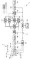
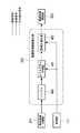
図1は本実施形態に係る撮像システムの概略構成図である。
撮像システム1は、撮像装置2と、画像処理装置3とを主な構成要素として備えている。
撮像装置2は、レンズ系100、絞り101、AFモータ102、カラーフィルタ103、およびCCD104を備えている。
画像処理装置3は、A/D変換器105、バッファ106、撮影制御部107、信号処理部108、領域分割部(領域分割手段)119、色空間変換部(色空間変換手段)109、階調変換部(階調変換手段)110、補正情報算出部(補正情報算出手段)111、最大彩度算出部(最大彩度算出手段)112、領域情報算出部(領域情報算出手段)113、彩度補正部(彩度作成手段)114、圧縮部115、出力部116、制御部117、および外部I/F部118を備えている。[First Embodiment]
Hereinafter, an image processing apparatus according to a first embodiment of the present invention and an imaging system including the same will be described with reference to the drawings.
FIG. 1 is a schematic configuration diagram of an imaging system according to the present embodiment.
The
The
The image processing apparatus 3 includes an A /
撮像装置2と画像処理装置3とは、画像処理装置3内のA/D変換器105および撮影制御部107を介して接続している。
撮像装置2に接続された撮影制御部107は、絞り101、AFモータ102、およびCCD104へ接続している。信号処理部108は領域分割部119へ接続している。領域分割部119は色空間変換部109へ接続している。色空間変換部109は階調変換部110、補正情報算出部111、最大彩度算出部112および領域情報算出部113へ接続している。階調変換部110は補正情報算出部111、最大彩度算出部112および彩度補正部114へ接続している。補正情報算出部111は彩度補正部114へ接続しており、最大彩度算出部112は彩度補正部114へ接続している。領域情報算出部113は補正情報算出部111へ接続している。彩度補正部114は圧縮部115へ接続している。圧縮部115は出力部116へ接続している。マイクロコンピュータなどの制御部117は、撮影制御部107、信号処理部108、色空間変換部109、階調変換部110、補正情報算出部111、最大彩度算出部112、領域情報算出部113、彩度補正部114、領域分割部119および圧縮部115と双方向に接続している。さらに、電源スイッチ、シャッターボタン、撮影時の各種モードの切り替えを行うためのインターフェースを備えた外部I/F部118も制御部117と双方向に接続している。The
The
上記構成を有する撮像システム1において、まず、全体の信号の流れについて以下に説明する。
撮像システム1は、ユーザまたは図示しない外部入力部によって、外部I/F部118を介してISO感度、露出などの撮影条件が設定された後、図示しないシャッターボタンを半押しにすることでプリ撮影モードに入る。In the
The
上記の状態において、レンズ系100、絞り101、カラーフィルタ103、CCD104を介して撮影された映像は、A/D変換器105にてデジタル信号へ変換される。A/D変換器105からの映像信号は、バッファ106を介して信号処理部108へ転送される。また、バッファ106からの信号は、撮影制御部107へも転送される。なお、本実施形態例においてCCD104は、RGB原色系の単板CCDを想定し、A/D変換器105による信号の階調幅を例えば12bitとする。 In the above state, an image photographed through the
撮影制御部107は、映像信号のAFエリア内のコントラスト情報を検出し、これが最大となるようにAFモータ102を制御することで合焦信号を得て距離情報が取得される。あるいは、プリ撮影時に映像信号を取得せず、図示しない外部赤外線センサを用いて主要被写体との距離を測定し、それに応じてAFモータ102を制御し、合焦位置における距離情報を得てもよい。
また、撮影制御部107は、信号中の輝度レベルや図示しない輝度センサを用いて適正露光となるよう絞り101およびCCD104の電子シャッター速度などを制御する。The
The photographing
次に、外部I/F部118を介して、ユーザによって図示しないシャッターボタンを全押しにされることにより本撮影が行われる。本撮影は、撮影制御部107にて求められた合焦条件および露光条件に基づいて行われ、これらの撮影時の情報は制御部117へ転送される。 Next, actual shooting is performed by fully pressing a shutter button (not shown) by the user via the external I /
バッファ106内の映像信号は、信号処理部108へ転送される。信号処理部108は、制御部115の制御に基づいてバッファ106上の単板状態の映像信号を読み出し、公知の補間処理、ホワイトバランス処理などが行われた三板状態の映像信号を生成し、領域分割部119へ転送する。 The video signal in the
領域分割部119は、転送された映像信号で表される画像を少なくとも一つ以上の領域に分割するように、映像信号を分割する。分割の方法は、例えば、画像を固定の矩形ブロックで分割したり、公知のテクスチャ解析を用いて画像から所定のテクスチャの領域を分割したり、映像信号の色情報を用いて所定の色を示す領域を分割したりする。映像信号は、色空間変換部109へ転送される。 The
色空間変換部109は、(1)式を用いてRGB信号をYCbCr信号に変換し、さらに(2)式を用いて輝度信号V、色相信号Hおよび彩度信号Cの色信号に変換する。 The color

あるいは(3)式および(4)式を用いてCIE−XYZ信号からCIE−L*a*b*信号への変換を行い、(5)式のように輝度、色相、彩度を求めてもよい。Alternatively, conversion from the CIE-XYZ signal to the CIE-L* a* b* signal is performed using Equations (3) and (4), and the luminance, hue, and saturation are obtained as in Equation (5). Good.
ただし、Xn、Yn、Znは、標準光における完全拡散反射面における値である。関数fは、例えばf(X/Xn)で(6)式の通りである。However, X n, Y n, Z n is a value in the perfect reflecting diffuser in the standard light. The function f is, for example, f (X / Xn ) as shown in equation (6).
なお、色変換の方法はこれらに限ったものではなく、例えば、LUT(ルックアップテーブル)を用いた変換でもよい。
このように色空間変換部109にて変換された色信号は、階調変換部110、補正情報算出部111、最大彩度算出部112、および領域情報算出部113へ転送される。Note that the color conversion method is not limited to these, and for example, conversion using an LUT (look-up table) may be used.
The color signal thus converted by the color
階調変換部110は、色空間変換部109から転送された輝度信号に対して後述する階調変換処理を行う。階調変換処理が行われた輝度信号は、補正情報算出部111、最大彩度算出部112、および彩度補正部114へ転送される。 The
次に、領域情報算出部113は、色空間変換部109から転送された色信号に対して、分割された領域のヒストグラム、輝度値の平均値、標準偏差、およびノイズ量の平均値を算出する。ノイズ量の算出法としては、例えば、以下の方法があげられる。 Next, the area
色信号の注目画素を中心とした例えば5×5の領域に対して標準偏差を算出し、それをノイズ量とする。また、上記領域中の全画素に対してノイズ量を算出し、それを平均したものを上記領域のノイズ量とする。ここで、ノイズ量の算出は、輝度信号V、色相信号Hおよび彩度信号Cのおのおのに対して行われ、(7)式のようにノイズ量Nを算出する。
N=aNV+bNH+cNC・・・(7)
ただし、NV、NH、NCはそれぞれ輝度信号、色相信号、および彩度信号に対するノイズ量を表し、a、b、cはそれぞれ重み係数を表す。A standard deviation is calculated for, for example, a 5 × 5 region centered on the target pixel of the color signal, and is used as the noise amount. Further, the amount of noise is calculated for all the pixels in the region, and the average of the amounts is used as the amount of noise in the region. Here, the noise amount is calculated for each of the luminance signal V, the hue signal H, and the saturation signal C, and the noise amount N is calculated as shown in Equation (7).
N = aNV + bNH + cNC (7)
However, NV , NH , and NC represent noise amounts for the luminance signal, hue signal, and saturation signal, respectively, and a, b, and c represent weighting factors, respectively.
補正情報算出部111は、色空間変換部109から転送された色信号と階調変換部110から転送された階調変換処理後の輝度信号および領域情報算出部113から転送されたノイズ量を用いて彩度補正に用いる補正情報の算出を行う。 The correction
最大彩度算出部112は、色空間変換部109および階調変換部110から転送された色信号を用いて最大彩度の算出を行う。
ここで、図5は彩度補正の説明図であり、YCbCr空間上にて表現している。図5におけるY1、Y2はそれぞれV1、V2に対応する。図5を用いて説明すると、最大彩度算出部112は、色空間変換部109から転送された信号V1、色相信号H、および彩度信号Cを用いて最大彩度maxC1を算出する。同様に、最大彩度算出部112は、階調変換部110から転送された信号V2を用いて最大彩度maxC2を算出する。The maximum
Here, FIG. 5 is an explanatory diagram of saturation correction, which is expressed in the YCbCr space. Y1 and Y2 in FIG. 5 correspond to V1 and V2 , respectively. Referring to FIG. 5, the maximum
彩度補正部114は、階調変換部110から転送された階調変換処理後の輝度信号および色信号と、補正情報算出部111から転送された補正情報と、最大彩度算出部112から転送された最大彩度の情報とを基に彩度信号の補正を行う。彩度補正部114における詳細な処理については後述する。 The
圧縮部115は、彩度補正部114から転送された色信号に対して公知のJPEG等の圧縮処理を行い、出力部116へ転送する。出力部114は、メモリカードなどへ圧縮信号を記録保存あるいは外部表示ディスプレイに映像信号を表示する。 The
次に、図1に示す各部の詳細な処理について以下に説明する。
まず、階調変換部110における詳細な処理について、図2を用いて説明する。
図2に示すように、階調変換部110は、バッファ200、局所領域分割部(局所領域分割手段)201、階調変換曲線算出部(階調変換曲線算出手段)202、および階調変換実施部(階調変換実施手段)203を備えている。Next, detailed processing of each unit shown in FIG. 1 will be described below.
First, detailed processing in the
As shown in FIG. 2, the
色空間変換部109はバッファ200に接続している。バッファ200は局所領域分割部201および階調変換実施部203に接続しており、局所領域分割部201は階調変換曲線算出部202に接続している。階調変換曲線算出部202は階調変換実施部203に接続しており、階調変換実施部203は補正情報算出部111、最大彩度算出部112および彩度補正部114に接続している。制御部117は、局所領域分割部201、階調変換曲線算出部202、および階調変換実施部203と双方向に接続している。 The color
上記構成を有する階調変換部110における処理について以下に説明する。
色空間変換部109は、バッファ200に色信号を転送する。局所領域分割部201は、バッファ200から転送された色信号を少なくとも一つ以上の領域に分割する。階調変換曲線算出部202は、局所領域分割部201から転送された色信号の輝度信号に対する階調変換曲線を設定する。Processing in the
The color
ここで、階調変換曲線算出部202における詳細な処理について、図3を用いて説明する。図3は、階調変換曲線算出部202の第1の構成例を示している。
図3に示すように、階調変換曲線算出部202は、バッファ300、平均輝度算出部(平均輝度算出手段)301、標準偏差算出部(標準偏差算出手段)302、階調変換曲線設定部(階調変換曲線設定手段)303、および階調変換曲線ROM(階調変換曲線保持手段)304を備えている。Here, detailed processing in the gradation conversion
As shown in FIG. 3, the gradation conversion
局所領域分割部201は、バッファ300に接続している。バッファ300は、平均輝度算出部301および標準偏差算出部302に接続している。平均輝度算出部301および標準偏差算出部302は階調変換曲線設定部303に接続しており、階調変換曲線ROM304は階調変換曲線設定部303に接続している。階調変換曲線設定部303は階調変換実施部203に接続している。 The local
上記構成を有する階調変換曲線算出部202における処理について以下に説明する。
平均輝度算出部301は、バッファ300から転送された領域における輝度信号の平均値を算出する。
次に、標準偏差算出部302は、バッファ300から転送された領域における輝度信号および平均輝度算出部301から転送された輝度信号の平均値を用いて標準偏差を算出する。
階調変換曲線設定部303は、平均輝度算出部301から転送された平均輝度値および標準偏差算出部302から転送された標準偏差の値を用いて階調変換曲線ROM304から階調変換に用いる階調変換曲線を設定する。Processing in the gradation conversion
The average
Next, the standard
The gradation conversion
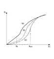
ここで、図6は、階調変換曲線の説明図を示している。
平均輝度値が所定値Th以下でかつ、標準偏差の値が所定値以下の場合、所定値以下の信号を強調するとノイズが増幅される可能性がある。したがって、階調変換曲線としては、例えば図6における(a)に示すように、Th以下の信号のコントラストをあまり強調しない階調変換曲線を設定する。
平均輝度値が所定値Th以下でかつ、標準偏差の値が所定値以上の場合、ノイズがすでに増幅されている可能性がある。したがって、階調変換曲線としては、例えば図6における(b)に示すように、所定値以下の信号のコントラストを下げる階調変換曲線を設定する。
平均輝度値が所定値Th以上の場合、階調変換処理によるノイズの増幅による影響が小さい。したがって、階調変換曲線としては平均輝度値付近のコントラストを強調させる階調変換曲線、例えば図6における(c)に示すように、平均輝度値Vave付近の信号を強調する階調変換曲線を設定する。
なお、この構成例では、階調変換曲線ROMを用いる例を示したが、これに限定されるものではない。例えば、ガンマ値を用いて階調変換曲線設定部303にてガンマ値を設定する構成も可能である。Here, FIG. 6 shows an explanatory diagram of the gradation conversion curve.
When the average luminance value is equal to or smaller than the predetermined value Th and the standard deviation value is equal to or smaller than the predetermined value, noise may be amplified when a signal equal to or smaller than the predetermined value is emphasized. Therefore, as the gradation conversion curve, for example, as shown in FIG. 6A, a gradation conversion curve that does not emphasize the contrast of signals below Th is set.
When the average luminance value is equal to or smaller than the predetermined value Th and the standard deviation value is equal to or larger than the predetermined value, the noise may already be amplified. Therefore, as the gradation conversion curve, for example, as shown in FIG. 6B, a gradation conversion curve that lowers the contrast of signals below a predetermined value is set.
When the average luminance value is equal to or greater than the predetermined value Th, the influence of noise amplification by the gradation conversion process is small. Therefore, as the gradation conversion curve, a gradation conversion curve for enhancing the contrast near the average luminance value, for example, a gradation conversion curve for enhancing the signal near the average luminance value Vave as shown in FIG. Set.
In this configuration example, the example using the gradation conversion curve ROM is shown, but the present invention is not limited to this. For example, a configuration in which the gamma value is set by the gradation conversion
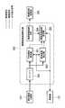
次に、補正情報算出部111における詳細な処理について、図4を用いて説明する。
図4に示すように、補正情報算出部111は、バッファ400、バッファ401、増幅率算出部(増幅率算出手段)402、および補正係数算出部(補正係数算出手段)403を備えている。Next, detailed processing in the correction
As shown in FIG. 4, the correction
色空間変換部109はバッファ400に接続しており、階調変換部110はバッファ401に接続している。バッファ400は増幅率算出部402および補正係数算出部403に接続しており、バッファ401は増幅率算出部402および補正係数算出部403に接続している。増幅率算出部402は補正係数算出部403に接続しており、領域情報算出部113は補正係数算出部403に接続している。補正係数算出部403は彩度補正部114に接続している。制御部117は増幅率算出部402および補正係数算出部403と双方向に接続している。 The color
上記構成を有する補正情報算出部111における処理について以下に説明する。
色空間変換部109から転送された輝度信号V1は、バッファ400に転送される。一方、階調変換部110から転送された輝度信号V2は、バッファ401に転送される。増幅率算出部402は、バッファ400およびバッファ401から転送された信号を用いて(8)式に示される増幅率Gの算出を行う。Processing in the correction
The luminance signal V1 transferred from the color
さらに、補正係数算出部403は、輝度信号V1、V2および領域情報算出部113から転送される領域の情報、例えば領域内のノイズ量の平均Nの情報を用いて(9)式に示される補正情報すなわち補正係数αの算出を行う。Further, the correction
ただし、Cは調整係数であり、0≦α≦1である。
増幅率や領域のノイズ量が大きいとき、階調変換処理によってノイズ成分が目立つため、この関数を用いて、彩度補正部114において後述する彩度信号の補正を行うことにより色ノイズ成分を抑制する。増幅率が1に近く、ノイズ成分が少ないとき,この関数の出力は1に近くなり、領域の情報による補正の影響は少なくなる。算出された補正係数は彩度補正部114に転送される。However, C is an adjustment coefficient, and 0 ≦ α ≦ 1.
When the amplification factor or the amount of noise in the area is large, noise components are conspicuous due to the gradation conversion processing. Therefore, using this function, the
次に、彩度補正部114の処理について図5を用いて説明する。
彩度補正部114は、最大彩度算出部112から転送された最大彩度の情報を用いて、階調変換前の輝度信号V1に対する彩度信号C1と最大彩度maxC1との比R1を(10)式に示すように算出する。
R1=C1/maxC1・・・(10)Next, the processing of the
The ratio of the
R1 = C1 / maxC1 (10)
次に、階調変換後の輝度信号V2に対する彩度信号C2の算出を(11)式に示すように行う。
C2=R1・maxC2・・・(11)
(11)式は、階調変換前の彩度信号と最大彩度信号との比が、階調変換後の彩度信号と最大彩度信号との比に等しいことを表している。Next, the saturation signal C2 is calculated with respect to the luminance signal V2 after the gradation conversion as shown in the equation (11).
C2 = R1 · maxC2 (11)
Equation (11) indicates that the ratio between the saturation signal before gradation conversion and the maximum saturation signal is equal to the ratio between the saturation signal after gradation conversion and the maximum saturation signal.
この処理により、輝度信号が階調変換処理によって変化しても、それに対応した彩度信号の変換を行うことができる。さらに、補正情報算出部111から転送される補正係数αの情報を用いて最終的な彩度信号C’2を(12)式を用いて算出する。
C’2=α・C2・・・(12)With this process, even if the luminance signal changes due to the gradation conversion process, the corresponding saturation signal can be converted. Further, the final saturation signal C ′2 is calculated using the equation (12) using the information of the correction coefficient α transferred from the correction
C ′2 = α · C2 (12)
本実施形態に係る画像処理装置およびこれを備えた撮像システムによれば、色相信号、彩度信号、および階調変換前後の輝度信号を用いて階調変換後の輝度信号に対応する彩度信号を演算すると共に、各信号に含まれるノイズ等の領域情報および階調変換前後の輝度信号を用いて補正情報を算出し、演算した階調変換後の輝度信号に対応する彩度信号に対して補正情報を用いて補正を行うことによって補正彩度信号を算出する。これにより、補正彩度信号についてもノイズ等の領域情報が反映されるので、階調変換処理によって色ノイズが増幅されるような場合においても、色ノイズを低減した高品位な映像信号を算出することができる。 According to the image processing apparatus and the imaging system including the image processing apparatus according to the present embodiment, the saturation signal corresponding to the luminance signal after the gradation conversion using the hue signal, the saturation signal, and the luminance signal before and after the gradation conversion. Correction information is calculated using area information such as noise and luminance signals before and after gradation conversion included in each signal, and the saturation signal corresponding to the calculated luminance signal after gradation conversion is calculated. A corrected saturation signal is calculated by performing correction using the correction information. As a result, the area information such as noise is also reflected in the corrected saturation signal, so that a high-quality video signal with reduced color noise is calculated even when the color noise is amplified by gradation conversion processing. be able to.
なお、上記実施例では、ハードウェアによる処理を前提としていたが、このような構成に限定される必要はない。例えば、CCD104からの映像信号を未処理のままのRawデータとして、ISO感度情報や映像信号サイズなどをヘッダ情報として出力し、別途ソフトウェアにて処理する構成も可能である。この場合、撮像システムは、CPU、RAM等の主記憶装置、上記処理の全て或いは一部を実現させるためのプログラムが記録されたコンピュータ読み取り可能な記録媒体を備えている。そして、CPUが上記記憶媒体に記録されているプログラムを読み出して、情報の加工・演算処理を実行することにより、上述の撮像システムと同様の処理を実現させる。ここでコンピュータ読み取り可能な記録媒体とは、磁気ディスク、光磁気ディスク、CD−ROM、DVD−ROM、半導体メモリ等をいう。 In the above embodiment, processing by hardware is assumed, but it is not necessary to be limited to such a configuration. For example, a configuration in which the video signal from the
図7に本実施形態のソフトウェアに関するフローを示す。
図1における処理と対応させると、S1にてヘッダ情報を読み込み、S2にて映像信号を入力する。信号処理部108に相当するS3にて所定の信号処理を行い、領域分割部119に相当するS4にて領域の分割を行う。色空間変換部109に相当するS5にて色空間の変換を行い、階調変換部110に相当するS6にて輝度信号に対する階調変換処理を行う。領域情報算出部113に相当するS7にて色信号の領域情報を抽出し、補正情報算出部111に相当するS8にて彩度補正に用いる補正情報の算出を行う。最大彩度算出部112に相当するS9にて最大彩度の算出を行い、彩度補正部114に相当するS10にて彩度信号の補正を行う。S11にて全画素に対して処理が行われたか判断し、全画素に対して処理が行われた場合、処理を終了する。FIG. 7 shows a flow relating to the software of this embodiment.
Corresponding to the processing in FIG. 1, header information is read in S1, and a video signal is input in S2. Predetermined signal processing is performed in S3 corresponding to the
〔第2の実施形態〕
次に、本発明の第2の実施形態について、図8を用いて説明する。
本実施形態に係る撮像システムが第1の実施形態と異なる点は、補正情報算出部にて行う補正情報の算出を制御する補正情報制御部を設けた点である。以下、本実施形態について、第1の実施形態と共通する点については説明を省略し、異なる点について主に説明する。[Second Embodiment]
Next, a second embodiment of the present invention will be described with reference to FIG.
The imaging system according to the present embodiment is different from the first embodiment in that a correction information control unit that controls calculation of correction information performed by the correction information calculation unit is provided. Hereinafter, the description of the present embodiment will be omitted with respect to the points common to the first embodiment, and different points will be mainly described.
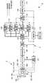
図8は本実施形態に係る撮像システムの概略構成図であり、第1の実施形態と同一の構成には同一の名称と番号を割り当てている。
撮像システム5は、撮像装置2と、画像処理装置6とを主な構成要素として備えている。
画像処理装置6において、色空間変換部109は、階調変換部110、最大彩度算出部112、領域情報算出部113、補正情報制御部(補正情報算出制御手段)130および補正情報算出部150に接続している。階調変換部110は最大彩度算出部112、彩度補正部114、補正情報算出部150および補正情報制御部130に接続している。補正情報制御部130は補正情報算出部150に接続している。補正情報算出部150は彩度補正部114へ接続している。マイクロコンピュータなどの制御部117は補正情報制御部130および補正情報算出部150へ双方向に接続されている。FIG. 8 is a schematic configuration diagram of the imaging system according to the present embodiment, and the same name and number are assigned to the same configuration as the first embodiment.
The
In the
上記構成を有する画像処理装置6における信号の流れについて以下に説明する。
補正情報制御部130は、色空間変換部109から転送された色信号と、階調変換部110から転送された階調変換処理後の輝度信号と、領域情報算出部113から転送された領域情報とを用いて、補正情報算出部150における補正情報の算出処理を停止するかどうか判断する。
例えば、色空間変換部109から転送された輝度信号における閾値をVth1、階調変換処理後の輝度信号における閾値をVth2、および領域におけるノイズ量の閾値をNthとした場合、補正情報制御部130は、V1>Vth1かつ、V2>Vth2かつN<Nthの場合には、補正情報算出部150の算出処理を行わないようにする。
なお、上記判定処理はすべての情報に対して行う必要はなく、例えば、ノイズ量のみで判定してもよい。
このように、補正情報算出部150は補正情報制御部130の情報に基づいて、補正情報の算出処理を停止する。A signal flow in the
The correction
For example, when the threshold value in the luminance signal transferred from the color
Note that the above determination process need not be performed for all information, and for example, the determination may be made based on only the noise amount.
As described above, the correction
図9は、階調変換部110内の階調変換曲線算出部202の第2の構成例を示している。
図9において、階調変換曲線算出部202は、バッファ900、ヒストグラム作成部(ヒストグラム算出手段)901、および累積正規化部902を備えている。
局所領域分割部201はバッファ900に接続しており、バッファ900はヒストグラム作成部901に接続している。ヒストグラム作成部901は累積正規化部902に接続しており、累積正規化部902は階調変換実施部203に接続している。制御部117はヒストグラム作成部901および累積正規化部902と双方向に接続している。FIG. 9 shows a second configuration example of the gradation conversion
In FIG. 9, the gradation conversion
The local
上記構成を有する階調変換曲線算出部202における処理について以下に説明する。
ヒストグラム作成部901は、バッファ900から転送された輝度信号に対するヒストグラムを作成する。
累積正規化部902は、ヒストグラム作成部901から転送されたヒストグラムに基づき累積処理を行い、累積ヒストグラムを作成する。これを階調幅に合わせて正規化することで階調変換曲線を生成する。例えば、輝度信号の入力が12bit、出力が12bitの場合、階調変換曲線は12bit入力12bit出力となる。
また、ヒストグラム作成部901にて任意のクリップ値を用いてヒストグラムの作成を行ってもよい。Processing in the gradation conversion
The histogram creation unit 901 creates a histogram for the luminance signal transferred from the buffer 900.
The accumulation normalization unit 902 performs accumulation processing based on the histogram transferred from the histogram creation unit 901 and creates a cumulative histogram. A gradation conversion curve is generated by normalizing this according to the gradation width. For example, when the luminance signal input is 12 bits and the output is 12 bits, the gradation conversion curve is a 12-bit input and a 12-bit output.
Further, the histogram creation unit 901 may create a histogram using an arbitrary clip value.
図10は、ヒストグラムに基づいた階調変換曲線算出の説明図を示している。
図10(a)は、ヒストグラム作成部901から算出されたヒストグラムと、縦軸の頻度に対するクリップ値を示している。図10(b)は、クリッピング処理によりクリップ値以上の頻度をクリップ値に置換したヒストグラムを示す。図10(c)は、オリジナルのヒストグラムとクリッピング処理後のヒストグラムを累積、正規化して得られた階調変換曲線を示す。
このように、ヒストグラムに基づいて算出された階調変換曲線は階調変換実施部203へ転送される。FIG. 10 shows an explanatory diagram of the gradation conversion curve calculation based on the histogram.
FIG. 10A shows a histogram calculated from the histogram creation unit 901 and clip values with respect to the frequency on the vertical axis. FIG. 10B shows a histogram in which the frequency equal to or higher than the clip value is replaced with the clip value by the clipping process. FIG. 10C shows a gradation conversion curve obtained by accumulating and normalizing an original histogram and a histogram after clipping processing.
Thus, the gradation conversion curve calculated based on the histogram is transferred to the gradation
なお、この階調変換曲線算出部202の構成は第1の実施形態でも実施可能であり、第1の実施形態に記載されている階調変換曲線部の構成にこの第2の実施例を適用することも可能である。 Note that the configuration of the gradation conversion
本実施形態に係る画像処理装置およびこれを備える撮像システムによれば、輝度信号およびノイズ量に基づいて補正情報の算出処理を停止することができるため、補正の必要がない高品位な信号に対しては処理の高速化が実現できる。 According to the image processing apparatus and the imaging system including the image processing apparatus according to the present embodiment, the correction information calculation process can be stopped based on the luminance signal and the amount of noise. Speeding up the processing.
なお、上記実施例では、ハードウェアによる処理を前提としていたが、このような構成に限定される必要はなく、別途ソフトウェアにて処理する構成も可能である。
図11に第2の実施例のソフトウェアに関するフローを示す。
第8図における処理と対応させると、S1にてヘッダ情報を読み込み、S2にて映像信号を入力する。信号処理部108に相当するS3にて所定の信号処理を行い、領域分割部119に相当するS4にて領域の分割を行う。色空間変換部109に相当するS5にて色空間の変換を行い、階調変換部110に相当するS6にて輝度信号に対する階調変換処理を行う。領域情報算出部113に相当するS7にて色信号の領域情報を抽出し、補正情報制御部130に相当するS20にて補正情報の制御情報を算出する。最大彩度算出部112に相当するS9にて最大彩度の算出を行い、補正情報算出部150に相当するS30にて彩度補正に用いる補正情報の算出を行う。S20の情報に応じてS30の処理を行わせないことも可能である。彩度補正部114に相当するS10にて彩度信号の補正を行う。S11にて全画素に対して処理が行われたか判断し、全画素に対して処理が行われた場合、処理を終了する。In the above embodiment, processing by hardware is assumed. However, it is not necessary to be limited to such a configuration, and a configuration in which processing is performed separately by software is also possible.
FIG. 11 shows a flow relating to the software of the second embodiment.
In correspondence with the processing in FIG. 8, header information is read in S1, and a video signal is input in S2. Predetermined signal processing is performed in S3 corresponding to the
1,5 撮像システム
2 撮像装置
3,6 画像処理装置
109 色空間変換部
110 階調変換部
111 補正情報算出部
112 最大彩度算出部
113 領域情報算出部
114 彩度補正部
130 補正情報制御部
201 局所領域分割部
202 階調変換曲線算出部
203 階調変換実施部
301 平均輝度算出部
302 標準偏差算出部
303 階調変換曲線設定部
304 階調変換曲線ROM
402 増幅率算出部
403 補正係数算出部
901 ヒストグラム作成部
902 累積正規化部DESCRIPTION OF
402 Amplification
Claims (12)
Translated fromJapanese前記映像信号を輝度信号、色相信号、および彩度信号からなる色空間へ変換する色空間変換手段と、
前記映像信号で表される画像中の領域の情報を算出する領域情報算出手段と、
前記色空間変換手段によって変換された前記輝度信号に対して階調変換を行って階調変換後の輝度信号を生成する階調変換手段と、
前記色空間変換手段によって変換された前記輝度信号および前記色相信号を用いて第1の最大彩度信号を算出するとともに、前記色空間変換手段によって変換された前記色相信号および前記階調変換手段によって生成された前記階調変換後の輝度信号を用いて第2の最大彩度信号を算出する最大彩度算出手段と、
前記色空間変換手段によって変換された前記輝度信号、前記階調変換手段によって生成された前記階調変換後の輝度信号、および前記領域情報算出手段によって算出された前記領域の情報に基づいて補正情報を算出する補正情報算出手段と、
前記最大彩度算出手段によって算出された前記第1の最大彩度信号および前記第2の最大彩度信号と前記補正情報算出手段によって算出された前記補正情報とに基づいて、前記色空間変換手段によって変換された前記彩度信号の補正を行う彩度補正手段と、
を有する画像処理装置。An image processing apparatus that performs gradation conversion on an input video signal and outputs the converted image signal,
Color space conversion means for converting the video signal into a color space consisting of a luminance signal, a hue signal, and a saturation signal;
Area information calculating means for calculating information of an area in the image represented by the video signal;
Gradation conversion means for performing gradation conversion on the luminance signal converted by the color space conversion means to generate a luminance signal after gradation conversion;
The luminance signal and the hue signal converted by the color space conversion unit are used to calculate a first maximum saturation signal, and the hue signal converted by the color space conversion unit and the gradation conversion unit Maximum saturation calculation means for calculating a second maximum saturation signal using the generated luminance signal after gradation conversion;
Correction information based on the luminance signal converted by the color space conversion means, the luminance signal after the gradation conversion generated by the gradation conversion means, and information on the area calculated by the area information calculation means Correction information calculating means for calculating
The color space conversion means based on the first maximum saturation signal and the second maximum saturation signal calculated by the maximum saturation calculation means and the correction information calculated by the correction information calculation means. Saturation correction means for correcting the saturation signal converted by
An image processing apparatus.
前記色空間変換手段によって変換された前記輝度信号および前記階調変換手段によって生成された前記階調変換後の輝度信号を用いて、前記色空間変換手段によって変換された前記輝度信号に対する増幅率を算出する増幅率算出手段と、
前記増幅率算出手段によって算出された前記増幅率および前記領域情報算出手段によって算出された前記領域の情報に基づいて補正係数を算出する補正係数算出手段と、
を有する請求項1に記載の画像処理装置。The correction information calculation means includes
Using the luminance signal converted by the color space conversion unit and the luminance signal after the gradation conversion generated by the gradation conversion unit, an amplification factor for the luminance signal converted by the color space conversion unit is obtained. A gain calculating means for calculating;
Correction coefficient calculation means for calculating a correction coefficient based on the amplification factor calculated by the amplification factor calculation means and information on the area calculated by the area information calculation means;
The image processing apparatus according to claim 1, comprising:
前記色空間変換手段によって変換された各信号におけるノイズ量を算出するノイズ量算出手段を有する請求項1または2に記載の撮像システム。The area information calculating means includes
The imaging system according to claim 1, further comprising a noise amount calculation unit that calculates a noise amount in each signal converted by the color space conversion unit.
前記最大彩度算出手段によって算出された前記第1の最大彩度信号と前記色空間変換手段によって変換された前記彩度信号との彩度比を算出する彩度比算出手段と、
前記彩度比算出手段によって算出された前記彩度比および前記最大彩度算出手段によって算出された前記第2の最大彩度信号に基づいて、前記階調変換後の輝度信号に対応する彩度信号を算出する彩度信号算出手段と、
前記補正情報算出手段によって算出された前記補正情報および前記彩度信号算出手段によって算出された前記階調変換後の輝度信号に対応する彩度信号に基づいて、補正彩度信号を算出する補正彩度信号算出手段と、
を有する請求項1から3のいずれかに記載の画像処理装置。The saturation correction means includes
Saturation ratio calculation means for calculating a saturation ratio between the first maximum saturation signal calculated by the maximum saturation calculation means and the saturation signal converted by the color space conversion means;
Based on the saturation ratio calculated by the saturation ratio calculation means and the second maximum saturation signal calculated by the maximum saturation calculation means, the saturation corresponding to the luminance signal after the gradation conversion A saturation signal calculating means for calculating a signal;
A corrected saturation signal for calculating a corrected saturation signal based on the correction information calculated by the correction information calculation unit and a saturation signal corresponding to the luminance signal after the gradation conversion calculated by the saturation signal calculation unit. Degree signal calculation means,
The image processing apparatus according to claim 1, comprising:
前記彩度比と前記第2の最大彩度信号とを乗算することによって前記階調変換後の輝度信号に対応する彩度信号を算出する請求項4に記載の画像処理装置。The saturation signal calculation means includes
The image processing apparatus according to claim 4, wherein a saturation signal corresponding to the luminance signal after the gradation conversion is calculated by multiplying the saturation ratio and the second maximum saturation signal.
前記補正情報算出手段によって算出された前記補正情報と前記彩度信号算出手段によって算出された前記階調変換後の輝度信号に対応する彩度信号とを乗算することにより、前記補正彩度信号を算出する請求項4に記載の画像処理装置。The corrected saturation signal calculation means includes:
Multiplying the correction information calculated by the correction information calculation means by the saturation signal corresponding to the luminance signal after the gradation conversion calculated by the saturation signal calculation means, the corrected saturation signal is The image processing apparatus according to claim 4 to calculate.
前記輝度信号を少なくとも1つ以上の局所領域に分割する局所領域分割手段と、
前記局所領域分割手段によって分割された局所領域に対する階調変換曲線を算出する階調変換曲線算出手段と、
前記階調変換曲線算出手段によって算出された階調変換曲線を用いて前記局所領域の輝度信号に対して階調変換を実施する階調変換実施手段と、
を有する請求項1から6のいずれかに記載の撮影装置。The gradation converting means includes
Local region dividing means for dividing the luminance signal into at least one local region;
A gradation conversion curve calculating means for calculating a gradation conversion curve for the local area divided by the local area dividing means;
Gradation conversion performing means for performing gradation conversion on the luminance signal of the local region using the gradation conversion curve calculated by the gradation conversion curve calculating means;
The imaging device according to claim 1, comprising:
階調変換曲線を複数保持する階調変換曲線保持手段と、
前記局所領域内の平均輝度値を算出する平均輝度算出手段と、
前記局所領域内の輝度信号の標準偏差を算出する標準偏差算出手段と、
前記平均輝度算出手段によって算出された前記平均輝度値および前記標準偏差算出手段によって算出された前記標準偏差に基づいて、前記階調変換曲線保持手段によって保持された前記複数の階調変換曲線の中から前記局所領域における階調変換曲線を設定する階調変換曲線設定手段と、
を有する請求項7に記載の撮影装置。The gradation conversion curve calculation means includes:
Gradation conversion curve holding means for holding a plurality of gradation conversion curves;
Average luminance calculating means for calculating an average luminance value in the local region;
Standard deviation calculating means for calculating a standard deviation of the luminance signal in the local region;
Based on the average luminance value calculated by the average luminance calculating unit and the standard deviation calculated by the standard deviation calculating unit, the plurality of gradation conversion curves held by the gradation conversion curve holding unit. Gradation conversion curve setting means for setting a gradation conversion curve in the local region from,
The imaging device according to claim 7, comprising:
ガンマ値を複数保持するガンマ値保持手段と、
前記局所領域内の平均輝度値を算出する平均輝度算出手段と、
前記局所領域内の輝度信号の標準偏差を算出する標準偏差算出手段と、
前記平均輝度算出手段によって算出された前記平均輝度値および前記標準偏差算出手段によって算出された前記標準偏差に基づいて、前記ガンマ値保持手段によって保持された前記複数のガンマ値の中から前記局所領域におけるガンマ値を設定するガンマ値設定手段と、
前記ガンマ値設定手段によって設定されたガンマ値に基づいてガンマ曲線を設定するガンマ曲線設定手段と、
を有する請求項7に記載の撮影装置。The gradation conversion curve calculation means includes:
Gamma value holding means for holding a plurality of gamma values;
Average luminance calculating means for calculating an average luminance value in the local region;
Standard deviation calculating means for calculating a standard deviation of the luminance signal in the local region;
Based on the average luminance value calculated by the average luminance calculating unit and the standard deviation calculated by the standard deviation calculating unit, the local region is selected from the plurality of gamma values held by the gamma value holding unit. Gamma value setting means for setting the gamma value in
Gamma curve setting means for setting a gamma curve based on the gamma value set by the gamma value setting means;
The imaging device according to claim 7, comprising:
前記局所領域内のヒストグラムを算出するヒストグラム算出手段と、
前記ヒストグラム算出手段によって算出された前記ヒストグラムに基づいて前記局所領域における階調変換曲線を設定する階調変換曲線設定手段と、
を有する請求項7に記載の撮影装置。The gradation conversion curve calculation means includes:
A histogram calculating means for calculating a histogram in the local region;
A gradation conversion curve setting means for setting a gradation conversion curve in the local region based on the histogram calculated by the histogram calculation means;
The imaging device according to claim 7, comprising:
Priority Applications (1)
| Application Number | Priority Date | Filing Date | Title |
|---|---|---|---|
| JP2007161638AJP2009004893A (en) | 2007-06-19 | 2007-06-19 | Image processor and imaging system equipped with same |
Applications Claiming Priority (1)
| Application Number | Priority Date | Filing Date | Title |
|---|---|---|---|
| JP2007161638AJP2009004893A (en) | 2007-06-19 | 2007-06-19 | Image processor and imaging system equipped with same |
Publications (1)
| Publication Number | Publication Date |
|---|---|
| JP2009004893Atrue JP2009004893A (en) | 2009-01-08 |
Family
ID=40320835
Family Applications (1)
| Application Number | Title | Priority Date | Filing Date |
|---|---|---|---|
| JP2007161638APendingJP2009004893A (en) | 2007-06-19 | 2007-06-19 | Image processor and imaging system equipped with same |
Country Status (1)
| Country | Link |
|---|---|
| JP (1) | JP2009004893A (en) |
Cited By (1)
| Publication number | Priority date | Publication date | Assignee | Title |
|---|---|---|---|---|
| JP2014165891A (en)* | 2013-02-28 | 2014-09-08 | Hitachi Ltd | Imaging apparatus and image signal processor |
Citations (2)
| Publication number | Priority date | Publication date | Assignee | Title |
|---|---|---|---|---|
| JP2004312467A (en)* | 2003-04-08 | 2004-11-04 | Olympus Corp | Imaging systems, image processing program |
| JP2006211610A (en)* | 2005-01-31 | 2006-08-10 | Olympus Corp | Imaging system |
- 2007
- 2007-06-19JPJP2007161638Apatent/JP2009004893A/enactivePending
Patent Citations (2)
| Publication number | Priority date | Publication date | Assignee | Title |
|---|---|---|---|---|
| JP2004312467A (en)* | 2003-04-08 | 2004-11-04 | Olympus Corp | Imaging systems, image processing program |
| JP2006211610A (en)* | 2005-01-31 | 2006-08-10 | Olympus Corp | Imaging system |
Cited By (1)
| Publication number | Priority date | Publication date | Assignee | Title |
|---|---|---|---|---|
| JP2014165891A (en)* | 2013-02-28 | 2014-09-08 | Hitachi Ltd | Imaging apparatus and image signal processor |
Similar Documents
| Publication | Publication Date | Title |
|---|---|---|
| JP3668014B2 (en) | Image processing method and apparatus | |
| KR101388130B1 (en) | Image processing apparatus and image processing method | |
| US8199227B2 (en) | Image-signal processing apparatus for performing space-variant image-signal processing | |
| JP4803284B2 (en) | Image processing apparatus and image processing program | |
| US8254675B2 (en) | Image processing apparatus, imaging apparatus and image processing program | |
| CN105960658B (en) | Image processing apparatus, image capturing apparatus, image processing method, and non-transitory storage medium that can be processed by computer | |
| US9185265B2 (en) | Image processing method and image processing apparatus for performing a tone correction to acquire a combined image | |
| KR20120025414A (en) | Image processing apparatus, image processing method, and recording medium | |
| WO2009060970A1 (en) | Signal processing apparatus and signal processing program | |
| JP5911525B2 (en) | Image processing apparatus and method, image processing program, and imaging apparatus | |
| US20100295977A1 (en) | Image processor and recording medium | |
| JP4544308B2 (en) | Image processing apparatus, imaging apparatus, method, and program | |
| JP6904788B2 (en) | Image processing equipment, image processing methods, and programs | |
| CN105993170A (en) | Image processing device, image capturing device, image processing method, and image processing program | |
| JP5782311B2 (en) | Imaging apparatus and control method thereof | |
| JP2007329619A (en) | Video signal processing apparatus, video signal processing method, and video signal processing program. | |
| JP2007329620A (en) | Imaging device and video signal processing program | |
| US8102446B2 (en) | Image capturing system and image processing method for applying grayscale conversion to a video signal, and computer-readable recording medium having recorded thereon an image processing program for applying grayscale conversion to a video signal | |
| JP2022186166A (en) | IMAGING DEVICE, CONTROL METHOD THEREOF, PROGRAM AND STORAGE MEDIUM | |
| KR20180138530A (en) | Detection apparatus, image processing apparatus, detection method, and image processing method | |
| JP5743456B2 (en) | Image processing apparatus, image processing method, and imaging apparatus | |
| JP2009004893A (en) | Image processor and imaging system equipped with same | |
| JP2019029781A (en) | Image processing system | |
| US8106977B2 (en) | Image capturing system and image processing method for applying grayscale conversion to a video signal, and computer-readable recording medium having recorded thereon an image processing program for applying grayscale conversion to a video signal |
Legal Events
| Date | Code | Title | Description |
|---|---|---|---|
| A621 | Written request for application examination | Free format text:JAPANESE INTERMEDIATE CODE: A621 Effective date:20100519 | |
| A131 | Notification of reasons for refusal | Free format text:JAPANESE INTERMEDIATE CODE: A131 Effective date:20111122 | |
| A02 | Decision of refusal | Free format text:JAPANESE INTERMEDIATE CODE: A02 Effective date:20120313 |