JP2009003412A - Polarization turning film with reduced color separation - Google Patents
Polarization turning film with reduced color separationDownload PDFInfo
- Publication number
- JP2009003412A JP2009003412AJP2008055218AJP2008055218AJP2009003412AJP 2009003412 AJP2009003412 AJP 2009003412AJP 2008055218 AJP2008055218 AJP 2008055218AJP 2008055218 AJP2008055218 AJP 2008055218AJP 2009003412 AJP2009003412 AJP 2009003412A
- Authority
- JP
- Japan
- Prior art keywords
- light
- turning film
- angle
- color separation
- prism
- Prior art date
- Legal status (The legal status is an assumption and is not a legal conclusion. Google has not performed a legal analysis and makes no representation as to the accuracy of the status listed.)
- Pending
Links
- 238000000926separation methodMethods0.000titleclaimsabstractdescription33
- 230000010287polarizationEffects0.000titleabstractdescription27
- 238000005286illuminationMethods0.000abstractdescription17
- 239000010408filmSubstances0.000description90
- 239000000463materialSubstances0.000description20
- 238000013459approachMethods0.000description13
- 230000003287optical effectEffects0.000description10
- 229920002492poly(sulfone)Polymers0.000description7
- 229920000139polyethylene terephthalatePolymers0.000description7
- 239000005020polyethylene terephthalateSubstances0.000description7
- 230000000052comparative effectEffects0.000description6
- 230000006870functionEffects0.000description6
- 238000000034methodMethods0.000description6
- 230000001419dependent effectEffects0.000description3
- 238000004519manufacturing processMethods0.000description3
- 230000007423decreaseEffects0.000description2
- 230000002708enhancing effectEffects0.000description2
- 239000004973liquid crystal related substanceSubstances0.000description2
- 239000012788optical filmSubstances0.000description2
- 238000001228spectrumMethods0.000description2
- 229910052717sulfurInorganic materials0.000description2
- NINIDFKCEFEMDL-UHFFFAOYSA-NSulfurChemical compound[S]NINIDFKCEFEMDL-UHFFFAOYSA-N0.000description1
- 239000011324beadSubstances0.000description1
- 230000005540biological transmissionEffects0.000description1
- 238000006243chemical reactionMethods0.000description1
- 239000003086colorantSubstances0.000description1
- 229920001577copolymerPolymers0.000description1
- 239000006185dispersionSubstances0.000description1
- 230000000694effectsEffects0.000description1
- 230000008571general functionEffects0.000description1
- 229920003229poly(methyl methacrylate)Polymers0.000description1
- -1polybutylenePolymers0.000description1
- 229920001748polybutylenePolymers0.000description1
- 229920000728polyesterPolymers0.000description1
- 239000011112polyethylene naphthalateSubstances0.000description1
- 229920000642polymerPolymers0.000description1
- 239000004926polymethyl methacrylateSubstances0.000description1
- 229920001021polysulfidePolymers0.000description1
- 239000005077polysulfideSubstances0.000description1
- 150000008117polysulfidesPolymers0.000description1
- 229920002578polythiourethane polymerPolymers0.000description1
- 239000011593sulfurSubstances0.000description1
Images


Classifications
- G—PHYSICS
- G02—OPTICS
- G02B—OPTICAL ELEMENTS, SYSTEMS OR APPARATUS
- G02B6/00—Light guides; Structural details of arrangements comprising light guides and other optical elements, e.g. couplings
- G02B6/0001—Light guides; Structural details of arrangements comprising light guides and other optical elements, e.g. couplings specially adapted for lighting devices or systems
- G02B6/0011—Light guides; Structural details of arrangements comprising light guides and other optical elements, e.g. couplings specially adapted for lighting devices or systems the light guides being planar or of plate-like form
- G02B6/0033—Means for improving the coupling-out of light from the light guide
- G02B6/005—Means for improving the coupling-out of light from the light guide provided by one optical element, or plurality thereof, placed on the light output side of the light guide
- G02B6/0053—Prismatic sheet or layer; Brightness enhancement element, sheet or layer
- G—PHYSICS
- G02—OPTICS
- G02B—OPTICAL ELEMENTS, SYSTEMS OR APPARATUS
- G02B5/00—Optical elements other than lenses
- G02B5/30—Polarising elements
- G—PHYSICS
- G02—OPTICS
- G02B—OPTICAL ELEMENTS, SYSTEMS OR APPARATUS
- G02B6/00—Light guides; Structural details of arrangements comprising light guides and other optical elements, e.g. couplings
- G02B6/0001—Light guides; Structural details of arrangements comprising light guides and other optical elements, e.g. couplings specially adapted for lighting devices or systems
- G02B6/0011—Light guides; Structural details of arrangements comprising light guides and other optical elements, e.g. couplings specially adapted for lighting devices or systems the light guides being planar or of plate-like form
- G02B6/0033—Means for improving the coupling-out of light from the light guide
- G02B6/0056—Means for improving the coupling-out of light from the light guide for producing polarisation effects, e.g. by a surface with polarizing properties or by an additional polarizing elements
Landscapes
- Physics & Mathematics (AREA)
- General Physics & Mathematics (AREA)
- Optics & Photonics (AREA)
- Planar Illumination Modules (AREA)
- Liquid Crystal (AREA)
- Optical Elements Other Than Lenses (AREA)
- Light Guides In General And Applications Therefor (AREA)
- Polarising Elements (AREA)
Abstract
Description
Translated fromJapanese本発明は、概して、表面からの輝度を増強するためのディスプレイ照明物品に関し、より詳細には、両面に、導光板からの光を向け直し、偏光出力を提供し、色分解を低減する構造を有する転向フィルムに関する。 The present invention relates generally to display lighting articles for enhancing brightness from a surface, and more particularly to a structure that redirects light from a light guide plate on both sides to provide polarized output and reduce color separation. It has a turning film.
液晶ディスプレイ(LCD)は、コスト及び性能において改善され続けており、多くのコンピュータ、計測装置及び娯楽応用のための好ましい表示方式になってきている。従来のラップトップ型コンピュータディスプレイで使用される透過型LCDは、バックライト付きディスプレイの一種であり、光を外側へ、すなわちLCDの方へ向けるために、LCDの背後に配置された光供給面を有する。小型かつ低コストでありながら十分に均一な明るさを有する適切なバックライト装置を提供するという課題は、2つの基礎的アプローチの1つに従って対処されている。第1のアプローチでは、光供給面が、広範囲の角度にわたって実質的に一定の輝度を有する高度に散乱した実質的に均等拡散の光分布を提供するために使用されている。この第1のアプローチに従って、軸上及び軸近くの輝度を増強することを目的として、より平行になった照明を提供するために、いくつかの輝度増強フィルムが、均等拡散分布を有するこの光の一部を向け直すのに提案されている。輝度増強フィルムに関して提案された解決手段の中には、例えば、米国特許第5,592,332号(Nishioら)、米国特許第6,111,696号(Allenら)及び米国特許第6,280,063号(Fongら)に記載されたものが含まれる。前掲の特許に記載された輝度増強フィルム(BEF)などの解決手段は、広視野角にわたってある程度増強された輝度を提供する。 Liquid crystal displays (LCDs) continue to improve in cost and performance and are becoming the preferred display scheme for many computer, instrumentation and entertainment applications. A transmissive LCD used in a conventional laptop computer display is a type of backlit display in which a light supply surface disposed behind the LCD is used to direct light outward, that is, toward the LCD. Have. The challenge of providing a suitable backlight device that is small and low cost but has sufficiently uniform brightness is addressed according to one of two basic approaches. In the first approach, the light supply surface is used to provide a highly scattered, substantially evenly diffused light distribution having a substantially constant brightness over a wide range of angles. In order to provide more parallel illumination for the purpose of enhancing the on-axis and near-axis brightness according to this first approach, several brightness enhancement films have been developed for this light with a uniform diffuse distribution. Suggested to redirect some. Among the solutions proposed for brightness enhancement films are, for example, US Pat. No. 5,592,332 (Nishio et al.), US Pat. No. 6,111,696 (Allen et al.) And US Pat. No. 6,280. , 063 (Fong et al.). Solutions such as the brightness enhancement film (BEF) described in the aforementioned patents provide a somewhat enhanced brightness over a wide viewing angle.
バックライト照明を提供する第2のアプローチは、導光板(LGP)を用いる。導光板(LGP)は、側方に配置されたランプ又は他の光源から入射光を受け入れ、光が狭い範囲の角度にわたってLGPから放射されるように、この光を、全内部反射(TIR)を使用して内部に誘導する。LGPからの出力光は、通常、垂線に対して、例えば70度以上など、かなり急角度である。この第2のアプローチでは、光方向転換物品の一種である転向フィルムが、LGPから放射された光出力を垂線の方へ向け直すために、その後使用される。光方向転換物品又は光方向転換フィルムと広く称される方向転換フィルム、例えば、ニューヨーク州ボールドウィンのClarex,Inc.から入手できるHSOT(高散乱光透過)導光パネルが備わっているものなどは、製造に際して拡散フィルム又はドット印刷の必要性なしに、この種の均一なバックライトを提供するための改善された解決手段を提供する。HSOT導光パネル及び他の種類の方向転換フィルムは、導光板からの光を垂線の方へ又は典型的には二次元の面に対する垂線近くである他の何らかの適切なターゲット角の方へ向け直すために、プリズム構造の配列を様々な組み合わせで使用する。一例として、米国特許第6,746,130号(Ohkawa)は、LGP照明のための転向フィルムとしての役割を果たす光制御シートを記載する。 A second approach for providing backlight illumination uses a light guide plate (LGP). A light guide plate (LGP) accepts incident light from a laterally placed lamp or other light source and directs this light to total internal reflection (TIR) so that the light is emitted from the LGP over a narrow range of angles. Use to guide inside. The output light from the LGP is usually quite steep with respect to the normal, for example 70 degrees or more. In this second approach, a turning film, a type of light redirecting article, is then used to redirect the light output emitted from the LGP towards the normal. Redirecting films, commonly referred to as light redirecting articles or light redirecting films, such as Clarke, Inc. of Baldwin, NY Improved solutions to provide this type of uniform backlight without the need for diffusing films or dot printing in production, such as those equipped with HSOT (High Scatter Light Transmission) light guide panels available from Provide a means. HSOT light guide panels and other types of redirecting films redirect light from the light guide plate towards a normal or some other suitable target angle that is typically near the normal to a two-dimensional surface. For this purpose, prism array arrangements are used in various combinations. As an example, US Pat. No. 6,746,130 (Ohkawa) describes a light control sheet that serves as a turning film for LGP illumination.
図1を参照すると、表示装置100における導光板10の総括的機能が示されている。光源12からの光は、入力面18で入射し、図のように典型的にくさび形である導光板10内に進む。光は、全内部反射(TIR)状態が妨げられるまで導光板10内を伝播し、その後、反射面142から反射される可能性があり、出力面16で導光板から抜け出る。この光は、その後、転向フィルム122に進み、例えば、LCD、他の種類の空間光変調器又は光を変調する他の二次元のバックライト付きコンポーネントなどの光ゲートデバイス120を照らすように向けられる。ほとんどの条件下で最適に表示するために、放射光は、垂線Vの周囲の比較的狭い角度の範囲にわたって提供される必要がある。偏光子124は、変調のための適切な偏光を有する光ゲートデバイス120を提供するために、照明経路に必ず配置される。しかしながら、転向フィルム122通過後の光は、実質的に偏光しないか、又はせいぜい僅かな偏光しか有しないため、偏光子124は、光の約半分を吸収しなければならない。この問題を克服するために、反射偏光子125が吸収偏光子124と転向フィルム122との間によく設けられる。 Referring to FIG. 1, the general function of the
反射偏光子の一種は、Koikeらの「Surface light source device with polarization function」と題する米国特許第5,982,540号及び米国特許第6,172,809号に開示されている。Koikeらの米国特許第5,982,540号及び米国特許第6,172,809号の開示は、導光板、1以上の偏光分離板、光方向修正要素(実質的に転向フィルム)及び偏光変換手段を有する面光源装置を示している。偏光分離板は、反射偏光子125の一種である。Koikeらの米国特許第5,982,540号の開示に記載された偏光分離板は、照明のS偏光成分とP偏光成分を分離するためにブリュースター角を利用する。このアプローチは、若干の光の偏光を提供するが、多くの従来の反射偏光フィルムの代替品の一種を提供するにすぎない。この解決手段は、依然として、(1つまたは複数の)別個の偏光フィルムの追加使用を必要とする。その上、Koikeらの米国特許第5,982,540号及び米国特許第6,172,809号の開示のアプローチは、偏光分離板に使用される材料の屈折率nが、導光板からの光の入射角に基づく狭い範囲内であることを必要とする。 One type of reflective polarizer is disclosed in US Pat. No. 5,982,540 and US Pat. No. 6,172,809 entitled “Surface light source device with polarization function” by Koike et al. Koike et al., US Pat. No. 5,982,540 and US Pat. No. 6,172,809, disclose a light guide plate, one or more polarization separators, a light redirecting element (substantially turning film) and polarization conversion. 1 shows a surface light source device having means. The polarization separation plate is a kind of the
明らかに、画像品質及び性能を落とすことなしに偏光された照明を提供するのに必要な全体的な構成要素の数が少ない方が有利なはずである。この目的を考慮して、偏光子125の構造を簡略化し、又は機能を組み合わせることによって別個のユニットとしてこの構成要素を除去するために提案されたいくつかの解決手段がある。機能を組み合わせようとする試みにおいて、Araiの「Surface Light Source Device Outputting Polarized Frontal Illumination Light」と題する米国特許第6,027,220号は、少なくとも一部が偏光された照明を生成可能な面光源装置を開示する。Araiの米国特許第6,027,220号が示すように、導光板10(図1)から出現する光の本質的に若干の偏光がある。加えて、転向フィルムによって本質的に行われるこの光の更なる偏光がある。一対の転向フィルムを用いる構成では、偏光をさらにほんのわずか得ることができる。Araiの米国特許第6,027,220号の開示に従って、各転向フィルムのための適切な材料を使用し、これらの材料を、それらの屈折率nに従って、導光板からの光の傾斜角に適合させるだけで、ある程度の偏光を提供する面光源が設計され得る。このアプローチは、ある程度の偏光を提供するという利点を有するが、屈折率nを単に特定することに基づいてどの程度の改善を得ることができるかには実際上限界がある。さらに、複数の転向フィルムを利用する実施形態は、照明システム設計にコスト、厚さ及び複雑さを加える。 Clearly, it would be advantageous to have fewer overall components required to provide polarized illumination without compromising image quality and performance. In view of this objective, there are several solutions proposed to eliminate this component as a separate unit by simplifying the structure of the
さらにもう1つのアプローチにおいて、Suzukiの「Apparatus for Increasing a Polarization Component, Light guiding Unit, Liquid Crystal Display and Polarization Method」と題する米国特許第6,079,841号は、それ自体が偏光を供給するように設計された導光板を提供する。Suzukiの米国特許第6,079,841号の導光板は、一緒に積層され、好ましい偏光状態を得るために光のブリュースター角条件を提供するように配向された光ガイドの積み重ねを利用する。この方法は、光ガイド自体の内部に偏光要素を組み込んでいるという利点を有するが、この種のアプローチには欠点がある。導光板の複雑さと、半波長又は四分の一波長の板及び反射体の追加された必要性は、照明経路における別個の要素としての偏光子を除去することによって得られる利点を打ち消す。 In yet another approach, U.S. Patent No. 84, entitled "Apparatus for Incrementing a Polarization Component, Light guiding Unit, Liquid Crystal Display and Polarization Method" by Suzuki, 79, entitled "Polarization No. 1", 79 A designed light guide plate is provided. The light guide plate of Suzuki U.S. Pat. No. 6,079,841 utilizes a stack of light guides that are laminated together and oriented to provide the Brewster angle condition of light to obtain the preferred polarization state. While this method has the advantage of incorporating a polarizing element within the light guide itself, this type of approach has drawbacks. The complexity of the light guide plate and the added need for half-wave or quarter-wave plates and reflectors negates the advantages obtained by removing the polarizer as a separate element in the illumination path.
同時係属の米国特許出願第11/302,011号、米国特許出願第11/300,659号及びMiの「Polarizing turning film using total internal reflection」と題する米国特許第7,139,125号に開示されているアプローチは、転向フィルム内又はより広くはディスプレイの光方向転換素子内に偏光機能を組み込むものである。これらの方法は、光方向転換物品の配列及び構成の設計においてブリュースター角を用いることによって、単一の構成要素で光方向転換と偏光の両方を行う。 Disclosed in copending US patent application Ser. No. 11 / 302,011, US patent application Ser. No. 11 / 300,659 and US Pat. No. 7,139,125 entitled “Polarizing turning film using total internal reflection”. One approach is to incorporate a polarizing function in the turning film or more broadly in the light redirecting element of the display. These methods both light redirect and polarize in a single component by using Brewster angles in the design of the array and configuration of light redirecting articles.
上向きのプリズム構造を有する転向フィルムの1つの問題は、フィルム材料の屈折率の波長依存性による色分解である。
従って、偏光機能を他の構成要素と組み合わせることによって偏光された照明を提供しようとする試みがなされているが、これらの試みは満足のいく解決手段を提供していないことが分かる。その結果、低減された構成要素の数及び低減された色分解を有する偏光された照明を提供する転向フィルム解決手段又はバックライトユニット解決手段の必要性がある。 Thus, although attempts have been made to provide polarized illumination by combining the polarization function with other components, it can be seen that these attempts do not provide a satisfactory solution. As a result, there is a need for turning film solutions or backlight unit solutions that provide polarized illumination with a reduced number of components and reduced color separation.
本発明は、光入射面及び光出射面を備え、前記出射面上に第1のプリズム構造を、前記光入射面上に第2のプリズム構造又はレンズ構造を備える転向フィルムであって、
(a)第1のプリズム素子が、遠い底角(β1)及び近い底角(β2)を特徴とし、
(b)第2のプリズム又はレンズ素子が、遠い底角(γ1)及び近い底角(γ2)を特徴とし、
副段落(a)及び(b)における角度の値が、前記出射面上の第1のプリズム素子のみを備える同じフィルムと比べて低減された色分解度を提供するように選択されることを条件とする転向フィルムを提供する。The present invention is a turning film comprising a light incident surface and a light exit surface, a first prism structure on the exit surface, and a second prism structure or lens structure on the light entrance surface,
(A) the first prism element is characterized by a far base angle (β1 ) and a close base angle (β2 );
(B) the second prism or lens element is characterized by a far base angle (γ1 ) and a close base angle (γ2 );
Provided that the angle values in sub-paragraphs (a) and (b) are selected to provide a reduced degree of color separation compared to the same film comprising only the first prism element on the exit surface. To provide a turning film.
本発明は、また、本発明の転向フィルムを用いるバックライトも含む。 The present invention also includes a backlight using the turning film of the present invention.
本発明の利点は、本発明が、主角の範囲にわたって入射し、低減された色分解を有する照明のための、転向フィルムと偏光子の機能を兼ね備える単一の構成要素を提供することである。 An advantage of the present invention is that it provides a single component that combines the functions of a turning film and a polarizer for illumination incident over a range of principal angles and having reduced color separation.
本明細書は、本発明の主題を特に指摘し、明確に請求する特許請求の範囲で締め括るが、本発明は、添付図面とともに解釈したとき、以下の説明からよりよく理解されるであろうと考えられる。 While the specification concludes with claims that particularly point out and distinctly claim the subject matter of the invention, the invention will be better understood from the following description when taken in conjunction with the accompanying drawings. Conceivable.
本説明は、特に、本発明による装置の一部を形成し、又は本発明による装置とより直接的に協働する要素を対象とする。具体的に図示し、または説明しない要素も、当業者に周知の様々な形を取り得ることを理解すべきである。 The present description is directed in particular to elements that form part of the device according to the invention or that cooperate more directly with the device according to the invention. It should be understood that elements not specifically shown or described may take various forms well known to those skilled in the art.
上記の背景技術の欄で述べたように、照明経路における他の構成要素内に偏光機能を組み込むことによって照明装置全体の複雑さを低減しようとする試みがなされている。本発明のアプローチは、転向フィルムの、より広くはディスプレイの光方向転換素子の色分解を低減することである。前述の従来のアプローチと異なり、本発明の方法は、光方向転換物品の配列と構成の設計において、両面にマイクロ構造を用いることによって、単一の構成要素で光方向転換と偏光の両方を行う。 As noted in the Background section above, attempts have been made to reduce the overall complexity of the lighting device by incorporating polarization functionality within other components in the illumination path. The approach of the present invention is to reduce the color separation of the turning film, and more broadly the light redirecting element of the display. Unlike the previous approach described above, the method of the present invention performs both light redirection and polarization in a single component by using a micro structure on both sides in the design of the arrangement and configuration of the light redirecting article. .
転向フィルム
当技術分野で周知であり、背景技術で述べたように、転向フィルムは、広く光方向転換物品又は光方向転換フィルムと称され、導光板から放射されるおおよそ平行な光出力を、大きくずれた角度から垂線の方へ又は見える方向へ向け直す光学フィルムである。Turning film As is well known in the art and described in the background art, turning films are broadly referred to as light redirecting articles or light redirecting films, which greatly increase the roughly parallel light output emitted from a light guide plate. It is an optical film that redirects from a deviated angle toward a perpendicular or in a visible direction.
本発明の装置は、典型的にプリズムのように成形した光方向転換構造を使用する。より正規の定義では、本来のプリズムは、少なくとも2つの平坦な面を有する。しかしながら、光方向転換構造の1以上の面がすべての実施形態において平坦である必要はなく、湾曲し又は複数の切断面を有していてもよいため、本明細書ではより一般的な用語である「プリズム構造」が使用される。 The apparatus of the present invention uses a light redirecting structure that is typically shaped like a prism. In a more regular definition, a natural prism has at least two flat surfaces. However, one or more surfaces of the light redirecting structure need not be flat in all embodiments, and may be curved or have multiple cut surfaces, so in the more general terms herein. Some “prism structure” is used.
以前に与えられた背景資料において述べられたように、従来の転向フィルムは、導光板又は類似の光供給要素から、典型的に垂線から60度以上の斜めの入射角で受け取った光を方向転換する。転向フィルムは、通常、導光板からの光を垂線の方へ向け直すために、典型的にプリズム形状で、かつ様々な寸法の屈折構造の配列を用いる。これらはフィルムとして設けられるため、垂線は、フィルムの二次元の平面に対するものとみなされる。 As stated in the background material given earlier, conventional turning films redirect light received from a light guide plate or similar light supply element at an oblique incident angle typically 60 degrees or more from the normal. To do. The turning film is typically prismatic and uses an array of refractive structures of various dimensions to redirect the light from the light guide plate toward the normal. Since they are provided as films, the normal is considered to be relative to the two-dimensional plane of the film.
図1を参照して示したように、光源12は、導光板10の側方に置かれている。その上面及び/又はその底面にマイクロ構造を有する導光板10のこの位置決めと設計は、転向フィルムの必要とされる角度作用及び設計レイアウトを決定する。ある範囲の導光板10の性能条件のために、同時係属の米国特許出願第11/302,011号、米国特許出願第11/300,659号及びMiの「Polarizing turning film using total internal reflection」と題する米国特許第7,139,125号に開示されている光方向転換物品は、図1の配列における従来の転向フィルム122を置き換えるのに使用することができ、偏光子124と反射偏光子125のどちらか又は両方の性能要件をなくし、又は少なくとも最小限に抑えるのに十分な偏光を提供することができる。 As shown with reference to FIG. 1, the
米国特許第7,139,125号の図3Aに対応する図2Aを参照すると、単一波長の光を放射する導光板10とともに使用される偏光転向フィルム20の概略断面図が示されており、主要な角及び幾何学的関係を示している。転向フィルム20は、上向き、すなわちLC装置又はその他の光変調器の方へ向いたいくつかのプリズム構造を有し、各構造は、近い面24(図1の実施形態に示したように、光源12に対して近いことを意味する)及び遠い面26を有し、両面とも、水平Hに対して、頂角αと、遠い底角β1及び近い底角β2とによって決定されるように、フィルムの垂線方向Vから見て傾斜している。導光板10からの光は、中心的な入力主角θinに係る角度の狭い範囲にわたって入射する。転向フィルム20の構造化された出力面からLCディスプレイ素子に送られる光の出力角θoutは、式(1)で示されるように、中心的な入力主角θin、転向フィルム20の屈折率n及び平面22に対して斜めの角度で遠い面26が傾けられる遠い底角β1を含むいくつかの要因によって決定される。Referring to FIG. 2A corresponding to FIG. 3A of US Pat. No. 7,139,125, there is shown a schematic cross-sectional view of a

導光板からの入射光は、入射光の大部分が主角の±10度以内になるように、主角を中心とする角の一群にわたって入射する。式(1)および後の式は、主角として入力角θinを使用する。Incident light from the light guide plate is incident over a group of angles centered on the principal angle so that most of the incident light is within ± 10 degrees of the principal angle. Equation (1) and the following equations use the input angle θin as the principal angle.
導光板10から単一波長の光線R1が放射されるとき、転向フィルム20から出る一条の光線が存在することが注目される。しかしながら、冷陰極蛍光灯(CCFL)と結合されたほとんどの一般に使用される導光板は、常に、複数の波長の光を放射し、又は連続した波長スペクトルの光さえも放射する。図2Bは、光線R1が複数の波長、例えば、赤色の650nm、緑色の550nm、青色の450nmなどを示すことを除いて、図2Aと同じである。図2Bは、転向フィルム20に関する色分解の問題、すなわち、3つの波長の光線30a、30b、30cが転向フィルム20内で分解し、さらにそれらが転向フィルム20から出現するときに分解することを説明する。典型的な材料の屈折率は波長とともに減少するため、図2Bに示される光線30a、30b、30cは、それぞれ、青色、緑色及び赤色の光を表し得る。 It is noted that when a single wavelength ray R1 is emitted from the
図2Cは、色分解に関する別の可能性を示す。図2Bの光路と同じ光路をたどるより長い波長の光線30b(緑色光)、30c(赤色光)は、遠い面に当たって遠い面26から出現する。より短い波長の光線30a(青色光)は、より高い屈折率であると考えられ、図2Cの異なる光路をたどる。光線30aは、遠い面26に当たり、その後、全内部反射によって近い面に向かって反射され、最後に、近い面24から出現する。 FIG. 2C shows another possibility for color separation. Longer wavelength rays 30b (green light) and 30c (red light) that follow the same optical path as in FIG. 2B emerge from the
図2Dは、色分解に関するさらに別の可能性を示す。図2Bの光路と同じ光路をたどるより長い波長の光線30b(緑色光)、30c(赤色光)は、遠い面に当たって遠い面26から出現する。より短い波長の光線30a(青色光)は、より高い屈折率であると考えられ、図2Dの異なる光路をたどる。光線30aは、遠い面26に当たり、その後、全内部反射によって近い面に向かって反射され、さらに、導光板の方へ屈折し、又は後方反射される。この場合、光線30aは、転向フィルムから直接出現しない。 FIG. 2D shows yet another possibility for color separation. Longer wavelength rays 30b (green light) and 30c (red light) that follow the same optical path as in FIG. 2B emerge from the
図2C及び図2Dのどちらにおいても、より短い波長の光は、より長い波長の光とは全く異なる経路を取り、大きな色分解の問題が生じる。 In both FIG. 2C and FIG. 2D, shorter wavelength light takes a completely different path than longer wavelength light, resulting in significant color separation problems.
色分解は、転向フィルムが特定の方向から見られるとき、不快な色の見えを引き起こす。この問題は、上向きのプリズム構造を有する転向フィルムに生じるが、下向きのプリズム構造を有する転向フィルムにはそれほど生じない。 Color separation causes an unpleasant color appearance when the turning film is viewed from a particular direction. This problem occurs in turning films having an upward prism structure, but not so much in turning films having a downward prism structure.
周知のように、あらゆる光学材料の屈折率は、波長依存である(Modern Optical Engineering,Warren J. Smith,McGraw−Hill,2000)。コーシーの屈折率分散式によれば、光学材料の屈折率は、式(2)によって決定される。 As is well known, the refractive index of any optical material is wavelength dependent (Modern Optical Engineering, Warren J. Smith, McGraw-Hill, 2000). According to Cauchy's refractive index dispersion formula, the refractive index of the optical material is determined by formula (2).
式中、a、b及びcは、所定の波長で測定された屈折率から個々の材料ごとに解かれた定数である。 In the formula, a, b and c are constants solved for each material from the refractive index measured at a predetermined wavelength.
式(1)及び式(1.1)によれば、出力角θoutは、式(2)に関するように、転向フィルム材料の屈折率の波長依存のために、波長依存である。According to Equation (1) and Equation (1.1), the output angle θout is wavelength dependent because of the wavelength dependence of the refractive index of the turning film material, as for Equation (2).
図3は、2つの一般に使用される光学材料の屈折率の波長依存の例を示す。ポリ(エチレンテレフタレート)(PET)の屈折率は、入射波長が375nmから988nmに増大するとき、1.8034から1.7367に減少する。ポリスルホンに関しては、同じスペクトルにおける屈折率の変動が0.1037である。PETに関しては、屈折率nが、450nmの波長λでは約1.787、550nmでは1.766、650nmでは1.754である。ポリスルホンに関しては、屈折率nが、450nm(青色光)の波長λでは約1.670、550nm(緑色光)では1.642、650nm(赤色光)では1.628である。 FIG. 3 shows an example of the wavelength dependence of the refractive index of two commonly used optical materials. The refractive index of poly (ethylene terephthalate) (PET) decreases from 1.8034 to 1.7367 when the incident wavelength increases from 375 nm to 988 nm. For polysulfone, the refractive index variation in the same spectrum is 0.1037. For PET, the refractive index n is about 1.787 at a wavelength λ of 450 nm, 1.766 at 550 nm, and 1.754 at 650 nm. For polysulfone, the refractive index n is about 1.670 at a wavelength λ of 450 nm (blue light), 1.642 at 550 nm (green light), and 1.628 at 650 nm (red light).
色分解度(DCS)
本発明をよりよく理解するために、定量化された色分解度が有用であると考えられる。色分解を測定するための異なる方法もあるが、本発明における色分解度は、以下の式で定義されるように、出力角θoutの二乗平均平方根の観点から測定される。Color separation (DCS)
In order to better understand the present invention, a quantified degree of color separation is considered useful. Although there are different methods for measuring color separation, the degree of color separation in the present invention is measured in terms of the root mean square of the output angle θout as defined by the following equation.
<>という表記は、400nmから700nmの波長にわたる平均値を表す。 The notation <> represents an average value over a wavelength of 400 nm to 700 nm.
簡略化したバージョンでは、3つの波長450nm、550nm及び650nmにおいてのみ、出力角θoutが考慮される。平均値は、以下の式で定義される。In the simplified version, the output angle θout is considered only at the three wavelengths 450 nm, 550 nm and 650 nm. The average value is defined by the following formula.
以下の例では、平均値の簡略化したバージョンが使用される。それは、比較のために十分役立つ。 In the following example, a simplified version of the average value is used. It is useful enough for comparison.
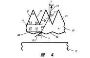
図4及び図5を参照すると、本発明の改善された転向フィルム20の主な特徴が示されている。プリズム構造は、この場合もやはり上向きである(より一般には、見る人の方と、LC装置又はその他の光変調器の方へ外へ向いている)。各プリズム構造は、光源12(図1)の位置に対して、近い面24及び遠い面26を有する。遠い面26は、図2Aに示したように、光の放射面又は出射面である。図4を参照すると、上向きのプリズム構造に加えて、導光板10の方へ向いた下向きのプリズム構造があり、下向きのプリズム構造は、近い底角γ2及び遠い底角γ1(図1の実施形態に示したように、光源12に対して近い又は遠いことを意味する)を特徴とする。転向フィルム20の構造化された出力面からLCディスプレイ素子に送られる光の出力角θoutは、中心的な入力主角θin、転向フィルム20の屈折率n、水平方向Hに対して斜めの角度で遠い面26が傾けられる底角β1及び水平方向Hに対して斜めの角度で近い面28が傾けられる近い底角γ2を含むいくつかの要因によって決定される。4 and 5, the main features of the
本発明の実施形態では、出力角θoutは、式(3)によって示されるように、入力角θin、プリズム構造の屈折率n、遠い底角β1及び近い底角γ2によって決定される。In an embodiment of the present invention, the output angle θout is determined by the input angle θin , the refractive index n of the prism structure, the far base angle β1 and the close base angle γ2 as shown by equation (3). .
以下の表1に関する考察を読むと、式(3)で求められる出力角θoutは、波長依存がより少ないことが明らかになるであろう。Reading the discussion regarding Table 1 below, it will be apparent that the output angle θout determined by Equation (3) is less wavelength dependent.
図4を振り返って見ると、遠い面26及び近い面28に与えられた(平面22に対する)適切な斜めの斜面によって、近い面28上の主光線とも称される中心的な照明光線R1に係る入射光は、ターゲット角、すなわちフィルムの垂線方向Vの方へ適切に向け直される。一実施形態では、各プリズム構造が出力面の一端から他端までのラインにおいて延長するように、プリズム構造は、転向フィルム20の表面に沿った延長方向に直線的に延長される。例えば図4のような断面図に関して、直線延長方向は、紙面に対して垂直である。この配列が転向フィルム20の製造のための利点を有することは十分理解され得る。しかしながら、プリズム構造がそのような延長された直線的に配列される必要はない。重要なことは、図4の断面図に示したように、導光板10からの入射光の角度に対するプリズム構造の様々な面の角度関係である。 Looking back at FIG. 4, it is related to the central illumination ray R <b> 1, also referred to as the chief ray on the
図5を参照すると、上向きのプリズム構造に加えて、導光板10の方へ向いた下向きのレンズ構造がある。転向フィルム20の構造化された出力面からLCディスプレイ素子に送られる光の出力角θoutは、中心的な入力主角θin、転向フィルム20の屈折率n、水平方向Hに対して斜めの角度で遠い面26が傾けられる底角β1及び導光板10の方へ向いた下向きのレンズ構造の曲率Cを含むいくつかの要因によって決定される。図4と同様に、底角γ1及びγ2もレンズ構造に関して定義され得る。Referring to FIG. 5, in addition to the upward prism structure, there is a downward lens structure facing the
遠い面26に与えられた(平面22に対する)適切な斜めの斜面によって、及びレンズ面30に与えられた適切な曲率Cによって、レンズ面30上の主光線とも称される中心的な照明光線R1に係る入射光は、ターゲット角、すなわちフィルムの垂線方向Vの方へ適切に向け直される。一実施形態では、各プリズム構造が出力面の一端から他端までのラインにおいて延長するように、プリズム構造は、転向フィルム20の表面に沿った延長方向に直線的に延長される。例えば図5のような断面図に関して、直線延長方向は、紙面に対して垂直である。この配列が転向フィルム20の製造のための利点を有することは十分理解され得る。しかしながら、プリズム構造がそのような延長された直線的に配列される必要はない。重要なことは、図5の断面図に示したように、導光板10からの入射光の角度に対するプリズム構造の様々な面の角度関係である。 A central
表1は、比較例と実施例のDCSを要約する。比較例1.1において、転向フィルムは、底角β1=66.0°、β2=66.0°を有する。転向フィルムは、ポリスルホン(その屈折率nは、450nm(青色光)の波長λでは約1.670、550nm(緑色光)では1.642、650nm(赤色光)では1.628である)かそれともPET(450nmの波長λではn≒1.787、550nmでは1.766及び650nmでは1.754)で作られている。3つの波長すべての主角が同じθin=70°である。式(1)、(3)、(5.1)及び(5.2)から、DCSは、ポリスルホンに関して2.16°ということになる。PETに関して、光は、図2Dに示したように、光線30aの経路を取り、従って、DCSは大きすぎるので定量化できない。重要なことは、DCSが非常に大きいことである。Table 1 summarizes the DCS of the comparative example and the example. In Comparative Example 1.1, the turning film has a base angle β1 = 66.0 °, β2 = 66.0 °. The turning film is polysulfone (its refractive index n is about 1.670 at a wavelength λ of 450 nm (blue light), 1.642 at 550 nm (green light), 1.628 at 650 nm (red light)) or PET (n≈1.787 at 450 nm wavelength λ, 1.766 at 550 nm and 1.754 at 650 nm). The principal angles of all three wavelengths are the same θin = 70 °. From equations (1), (3), (5.1) and (5.2), DCS is 2.16 ° for polysulfone. For PET, the light takes the path of
実施例1.2は、転向フィルムが、図4に示したように、その底面に追加のプリズム構造を有し、そのプリズム構造が、底角γ2=10.0°及びγ1=20°を特徴とすることを除いて、比較例1.1と同じである。一般に、条件γ1≧90°−θinが満たされる。本実施例の転向フィルムは、DCSが低減されることを示している。すなわち、DCSは、PETに関して1.23°であり、ポリスルホンに関して1.33°である。In Example 1.2, the turning film has an additional prism structure on its bottom surface, as shown in FIG. 4, and the prism structure has base angles γ2 = 10.0 ° and γ1 = 20 °. Is the same as Comparative Example 1.1. In general, the condition γ1 ≧ 90 ° −θin is satisfied. The turning film of this example shows that DCS is reduced. That is, DCS is 1.23 ° for PET and 1.33 ° for polysulfone.
実施例1.3は、底面のプリズム構造が、底角γ2=20.0°及びγ1=20°を特徴とすることを除いて、実施例1.2と同じである。DCSはさらに低減される。すなわち、DCSは、PETに関して0.79°であり、ポリスルホンに関して0.95°である。Example 1.3 is the same as Example 1.2 except that the bottom prism structure is characterized by a base angle γ2 = 20.0 ° and γ1 = 20 °. DCS is further reduced. That is, DCS is 0.79 ° for PET and 0.95 ° for polysulfone.
一般に、遠い底角β1は、好ましくは、50°から70°までの範囲である。In general, the far base angle β1 is preferably in the range of 50 ° to 70 °.
近い底角γ1は、好ましくは、10°から20°までの範囲である。この範囲外では、色分解度(DCS)は、依然として十分に大きいか、又は出力角の範囲が好ましくない。The close base angle γ1 is preferably in the range of 10 ° to 20 °. Outside this range, the degree of color separation (DCS) is still large enough or the range of output angles is not preferred.
異なる波長に様々な主角を提供する導光板
次に図6を参照すると、異なる波長に様々な主角を提供するために導光板10’を使用する本発明に従って色分解を低減する別の解決手段が示されている。導光板は、その底面及び上面にマイクロ構造を有し得る。発光ダイオード(LED)などの2つ以上の個別の光源は、異なる波長の光を生成する。3つの典型的な個別の光源201、202、203は、異なる波長を生成するように、導光板の側方に垂直に配置されている。個別の光源は、垂直方向及び水平方向の両方に移されることも可能である。個別の光源は、異なるサイズ又はその他の特性を有し得る。光源及び導光板の配列がオプティクスモデリング又は実験などの任意の知られた方法で適切に設計されるとき、導光板10’は、異なる波長に好ましい主角を提供することができる。相対的に、単一の従来のCCFL光源は、異なる波長のための出力光分布を単独で変更することができず、従って、この用途には適さない。しかしながら、異なる運転条件下の2つ以上のCCFLは、導光板と適切に結合されるとき、異なる波長に異なる主角を生成し得る。加えて、弱い拡散体126が転向フィルム20と光ゲートデバイス120の間に任意に設置され得る。弱い拡散体も色分解を若干低減するが、転向フィルムを通過する光にあまり多くの散乱を生じさせることができないため、色分解を完全に除去することはできない。Light Guide Plate Providing Various Principal Angles at Different Wavelengths Referring now to FIG. 6, another solution for reducing color separation in accordance with the present invention using light guide plate 10 'to provide various principal angles at different wavelengths. It is shown. The light guide plate may have a microstructure on its bottom and top surfaces. Two or more individual light sources, such as light emitting diodes (LEDs), generate light of different wavelengths. Three typical individual
表2は、様々な条件下で、異なる波長の光の主角を決定する個別の光源と結合された様々な導光板を使用して、転向フィルム20のDCSがどのように低減されるのかを説明する実施例と比較例を示す。 Table 2 illustrates how the DCS of turning
比較例2.1では、底角β1=66.0°、β2=66.0°である。転向フィルムは、ポリスルホンで作られている。3つの波長すべての主角が、同じθin=70°である。出力角θoutは、5°を上回って変化し、λ=450nmでは4.5°、λ=550nmでは8.0°、λ=650nmでは9.7°であり、それらは式(1)から算出することができる。DCSは、式(3)、(5.1)及び(5.2)から算出された2.16°である。In Comparative Example 2.1, the base angles β1 = 66.0 ° and β2 = 66.0 °. The turning film is made of polysulfone. The principal angles of all three wavelengths are the same θin = 70 °. The output angle θout varies by more than 5 °, 4.5 ° for λ = 450 nm, 8.0 ° for λ = 550 nm, and 9.7 ° for λ = 650 nm, which are derived from equation (1). Can be calculated. DCS is 2.16 ° calculated from Equations (3), (5.1), and (5.2).
実施例2.2は、主角が波長とともに変化することを除いて、比較例2.1と同じである。主角θinは、λ=450nmでは70°、550nmでは63°、λ=650nmでは61°である。結果として、出力角θoutは、1°より小さく変化し、λ=450nmでは4.5°、550nmでは4.1°、λ=650nmでは4.0°である。異なる波長に対する出力角のより小さい変化は、より少ない色分解を示しており、それは、0.22°というより小さいDCSにも反映されている。本実施例は、主角が波長とともに変化する光を放射する導光板を導入することによって、色分解度を低減することが可能であることを示唆している。青色光(λ=450nm)の主角は、赤色光(λ=650nm)の主角より大きい緑色光(λ=550nm)の主角より大きいことが好ましい。また、青色光と緑色光の主角間の差は、緑色光と赤色光の主角間の差より大きいことが好ましい。Example 2.2 is the same as Comparative Example 2.1 except that the principal angle varies with wavelength. The main angle θin is 70 ° at λ = 450 nm, 63 ° at 550 nm, and 61 ° at λ = 650 nm. As a result, the output angle θout changes less than 1 °, 4.5 ° at λ = 450 nm, 4.1 ° at 550 nm, and 4.0 ° at λ = 650 nm. A smaller change in output angle for different wavelengths indicates less color separation, which is also reflected in a DCS smaller than 0.22 °. This example suggests that the degree of color separation can be reduced by introducing a light guide plate that emits light whose principal angle changes with wavelength. The principal angle of blue light (λ = 450 nm) is preferably larger than the principal angle of green light (λ = 550 nm), which is larger than the principal angle of red light (λ = 650 nm). The difference between the main angles of blue light and green light is preferably larger than the difference between the main angles of green light and red light.
実施例2.3は、主角θinが、λ=450nmでは78°、550nmでは72°、λ=650nmでは70°であることを除いて、実施例2.2と同じである。したがって、出力角θoutは、実施例2.2の約4.0°と比べて、ほぼ9.0°になるように調整される。同様に、出力角θoutは、1°より小さく変化し、DCSは、0.29°という小さい値を有する。Example 2.3 is the same as Example 2.2 except that the principal angle θin is 78 ° at λ = 450 nm, 72 ° at 550 nm, and 70 ° at λ = 650 nm. Therefore, the output angle θout is adjusted to be approximately 9.0 ° as compared to approximately 4.0 ° in Example 2.2. Similarly, the output angle θout varies less than 1 ° and the DCS has a small value of 0.29 °.
実施例2.2と比較して、実施例2.4は、異なる底角及び主角を有する。底角は、β1=68.0°、β2=68.0°であり、主角θinは、λ=450nmでは78°、550nmでは72°、λ=650nmでは70°である。これらは、ほぼ0.0°になる、又は垂線方向に近い出力角θoutを作り出すように選択される。出力角θoutは、1°より小さく変化し、DCSは、0.40°という小さい値を有する。Compared to Example 2.2, Example 2.4 has a different base angle and principal angle. The base angles are β1 = 68.0 ° and β2 = 68.0 °, and the main angle θin is 78 ° at λ = 450 nm, 72 ° at 550 nm, and 70 ° at λ = 650 nm. These are selected to produce an output angle θout that is approximately 0.0 ° or close to the normal direction. The output angle θout varies less than 1 °, and DCS has a small value of 0.40 °.
実施例2.5は、主角θinが、λ=450nmでは71°、550nmでは66°、λ=650nmでは63°であることを除いて、実施例2.4と同じである。これらもまた、ほぼ0.0°になる、又は垂線方向に近い出力角θoutを作り出すように選択される。出力角θoutは、λ=450nmでは0.8°、550nmでは0.7°、λ=650nmでは−0.4°である。DCSは、0.54°という小さい値を有する。本実施例では、青色光(λ=450nm)の出力角は、赤色光(λ=650nm)の出力角より大きい緑色光(λ=550nm)の出力角より大きいが、実施例2.2から実施例2.4では、青色光(λ=450nm)の出力角は、赤色光(λ=650nm)の出力角より小さい緑色光(λ=550nm)の出力角より小さい。Example 2.5 is the same as Example 2.4 except that the main angle θin is 71 ° at λ = 450 nm, 66 ° at 550 nm, and 63 ° at λ = 650 nm. These are also selected to produce an output angle θout that is approximately 0.0 ° or close to the normal direction. The output angle θout is 0.8 ° at λ = 450 nm, 0.7 ° at 550 nm, and −0.4 ° at λ = 650 nm. DCS has a small value of 0.54 °. In this embodiment, the output angle of blue light (λ = 450 nm) is larger than the output angle of green light (λ = 550 nm), which is larger than the output angle of red light (λ = 650 nm). In Example 2.4, the output angle of blue light (λ = 450 nm) is smaller than the output angle of green light (λ = 550 nm), which is smaller than the output angle of red light (λ = 650 nm).
上記の実施例2.2から実施例2.5は、単なる例示である。その他の変形も全く可能である。 The above Example 2.2 to Example 2.5 are merely illustrative. Other variations are entirely possible.
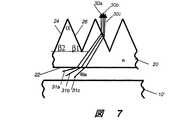
図7は、図6の分解図であり、導光板10’から出て、転向フィルム20から光線30a、30b、30cとして出現する異なる波長又は色の光線31a、31b、31cを示している。これらの光線は、非常に小さい角度分離を有する。 FIG. 7 is an exploded view of FIG. 6, showing
転向フィルム20を形成するための材料
本発明で使用される転向フィルム20は、硫黄含有ポリマー、特に、ポリチオウレタン、ポリスルフィドなどを含む、比較的高い屈折率を有する材料を使用して製造することができる。また、高屈折率の材料には、2004年8月12日に公開されたSadayoriらによる「Polycarbodiimide having high index of refraction and production method thereof」と題する米国特許出願公開第2004/0158021号に開示されている、熱安定性に優れ、高い加工性と成形性を有する、ポリカルボジイミド共重合体も含まれる。これらの材料の屈折率は、589nmで1.738から1.757まで変化した。また、Chisholmらによる「HIGH INDEX COATED LIGHT MANAGEMENT FILMS」と題する米国特許出願公開第2004/0109305号に開示されているように、ドープしたミクロスフェアを有する材料又はチタニア、ジルコニア及びバリアなどの高屈折率材料のビードも、1.7より小さい又は大きい高屈折率を示す。また、高屈折率の材料には、ポリエチレンナフタレート(PEN)及びポリブチレン2,6−ナフタレート(PBN)などの多くのポリエステルも含まれる。これらの材料は、Hebrinkらの「Method for making coPEN/PMMA multilayer optical films」と題する米国特許第6,830,713号において論じられているように、約1.64から約1.9の高さまで変化する屈折率を有する。高い屈折率を有するその他の周知の材料も使用することができる。Material for forming
本明細書で参照した特許及びその他の文献は、参照により組み込まれるものである。 Patents and other documents referred to herein are incorporated by reference.
10,10’ 導光板
12 光源
16 出力面
18 入力面
20 転向フィルム
22 平面
24 近い面
26 遠い面
30a,30b,30c 光線
31a,31b,31c 光線
34 プリズム構造
82 点光源
100,110 表示装置
120 光ゲートデバイス
122 転向フィルム
124 偏光子
125 反射偏光子
126 弱い拡散体
142 反射面
201 青色光の光源
202 緑色光の光源
203 赤色光の光源
α 頂角
β1 底角
β2 底角
γ1 底角
γ2 底角
n 屈折率
θin 入射角
θout 出力角
V フィルムの垂線方向
V1 遠い面上の垂線方向
H 水平方向
R1 中心的な照明光線10, 10 '
Claims (6)
Translated fromJapanese(a)前記第1のプリズム素子が、遠い底角(β1)及び近い底角(β2)を特徴とし、
(b)前記第2のプリズム又はレンズ素子が、遠い底角(γ1)及び近い底角(γ2)を特徴とし、
副段落(a)及び(b)における角度の値が、前記出射面上の第1のプリズム素子のみを備える同じフィルムと比べて低減された色分解度を提供するように選択されることを条件とする転向フィルム。A turning film comprising a light incident surface and a light exit surface, comprising a first prism structure on the exit surface and a second prism structure or lens structure on the light entrance surface;
(A) the first prism element is characterized by a far base angle (β1 ) and a close base angle (β2 );
(B) the second prism or lens element is characterized by a far base angle (γ1 ) and a close base angle (γ2 );
Provided that the angle values in subparagraphs (a) and (b) are selected to provide a reduced degree of color separation compared to the same film comprising only the first prism element on the exit surface. Turning film.
Applications Claiming Priority (1)
| Application Number | Priority Date | Filing Date | Title |
|---|---|---|---|
| US90549207P | 2007-03-07 | 2007-03-07 |
Publications (1)
| Publication Number | Publication Date |
|---|---|
| JP2009003412Atrue JP2009003412A (en) | 2009-01-08 |
Family
ID=39529450
Family Applications (1)
| Application Number | Title | Priority Date | Filing Date |
|---|---|---|---|
| JP2008055218APendingJP2009003412A (en) | 2007-03-07 | 2008-03-05 | Polarization turning film with reduced color separation |
Country Status (6)
| Country | Link |
|---|---|
| US (1) | US20080218858A1 (en) |
| EP (1) | EP1967789A1 (en) |
| JP (1) | JP2009003412A (en) |
| KR (1) | KR20080082543A (en) |
| CN (1) | CN101281270A (en) |
| TW (1) | TW200846781A (en) |
Cited By (2)
| Publication number | Priority date | Publication date | Assignee | Title |
|---|---|---|---|---|
| WO2015141369A1 (en)* | 2014-03-20 | 2015-09-24 | シャープ株式会社 | Illumination device and display device |
| CN106195766A (en)* | 2016-07-12 | 2016-12-07 | 京东方科技集团股份有限公司 | A kind of backlight, display device and control method thereof |
Families Citing this family (3)
| Publication number | Priority date | Publication date | Assignee | Title |
|---|---|---|---|---|
| US8659830B2 (en)* | 2009-12-21 | 2014-02-25 | 3M Innovative Properties Company | Optical films enabling autostereoscopy |
| US11187847B2 (en)* | 2017-06-06 | 2021-11-30 | 3M Innovative Properties Company | Backlight including wide-web turning film and reflective polarizer with quarter-wave retarder |
| CN107515439B (en)* | 2017-09-28 | 2019-10-08 | 京东方科技集团股份有限公司 | Light guide assembly, backlight source and display device |
Citations (2)
| Publication number | Priority date | Publication date | Assignee | Title |
|---|---|---|---|---|
| JPH0682634A (en)* | 1992-07-07 | 1994-03-25 | Sekisui Chem Co Ltd | Surface light source device |
| JP2001143515A (en)* | 1999-09-03 | 2001-05-25 | Mitsubishi Rayon Co Ltd | Prism sheet and surface light source element |
Family Cites Families (19)
| Publication number | Priority date | Publication date | Assignee | Title |
|---|---|---|---|---|
| KR0168879B1 (en) | 1992-12-25 | 1999-04-15 | 기따지마 요시또시 | Renticular lens, surface light source and liquid crystal display apparatus |
| US5982540A (en)* | 1994-03-16 | 1999-11-09 | Enplas Corporation | Surface light source device with polarization function |
| JP2915317B2 (en)* | 1995-02-28 | 1999-07-05 | インターナショナル・ビジネス・マシーンズ・コーポレイション | Light guide unit, liquid crystal display device and polarization method |
| US5825543A (en)* | 1996-02-29 | 1998-10-20 | Minnesota Mining And Manufacturing Company | Diffusely reflecting polarizing element including a first birefringent phase and a second phase |
| US6027220A (en) | 1996-11-19 | 2000-02-22 | Enplas Corporation | Surface light source device outputting polarized frontal illumination light |
| US6280063B1 (en)* | 1997-05-09 | 2001-08-28 | 3M Innovative Properties Company | Brightness enhancement article |
| US6808658B2 (en)* | 1998-01-13 | 2004-10-26 | 3M Innovative Properties Company | Method for making texture multilayer optical films |
| JP4011287B2 (en) | 2000-12-25 | 2007-11-21 | 株式会社エンプラス | Light control sheet, surface light source device, and liquid crystal display |
| US6811274B2 (en)* | 2002-12-04 | 2004-11-02 | General Electric Company | Polarization sensitive optical substrate |
| JP4397394B2 (en)* | 2003-01-24 | 2010-01-13 | ディジタル・オプティクス・インターナショナル・コーポレイション | High density lighting system |
| JP4249996B2 (en)* | 2003-02-10 | 2009-04-08 | 日東電工株式会社 | Lens material comprising polycarbodiimide copolymer |
| TWI274178B (en)* | 2003-05-22 | 2007-02-21 | Hitachi Chemical Co Ltd | Optical film and surface light source device using the same |
| JP4262113B2 (en)* | 2004-02-13 | 2009-05-13 | シチズン電子株式会社 | Backlight |
| US20060138702A1 (en)* | 2004-12-23 | 2006-06-29 | Biernath Rolf W | Method of making uniaxially oriented articles having structured surfaces |
| MX2007010903A (en)* | 2005-03-09 | 2007-12-05 | 3M Innovative Properties Co | Microreplicated article with moire reducing surface. |
| KR100739720B1 (en)* | 2005-08-16 | 2007-07-13 | 삼성전자주식회사 | Color filter-free liquid crystal display device |
| US7139125B1 (en)* | 2005-12-13 | 2006-11-21 | Eastman Kodak Company | Polarizing turning film using total internal reflection |
| US7633679B2 (en) | 2005-12-13 | 2009-12-15 | Skc Haas Display Films Co., Ltd. | Polarizing turning film |
| US20070133226A1 (en) | 2005-12-13 | 2007-06-14 | Eastman Kodak Company | Polarizing turning film with multiple operating orientations |
- 2008
- 2008-03-05JPJP2008055218Apatent/JP2009003412A/enactivePending
- 2008-03-06CNCNA2008100966810Apatent/CN101281270A/enactivePending
- 2008-03-06TWTW097107777Apatent/TW200846781A/enunknown
- 2008-03-07EPEP08152486Apatent/EP1967789A1/ennot_activeWithdrawn
- 2008-03-07KRKR1020080021720Apatent/KR20080082543A/ennot_activeWithdrawn
- 2008-03-07USUS12/074,978patent/US20080218858A1/ennot_activeAbandoned
Patent Citations (2)
| Publication number | Priority date | Publication date | Assignee | Title |
|---|---|---|---|---|
| JPH0682634A (en)* | 1992-07-07 | 1994-03-25 | Sekisui Chem Co Ltd | Surface light source device |
| JP2001143515A (en)* | 1999-09-03 | 2001-05-25 | Mitsubishi Rayon Co Ltd | Prism sheet and surface light source element |
Cited By (2)
| Publication number | Priority date | Publication date | Assignee | Title |
|---|---|---|---|---|
| WO2015141369A1 (en)* | 2014-03-20 | 2015-09-24 | シャープ株式会社 | Illumination device and display device |
| CN106195766A (en)* | 2016-07-12 | 2016-12-07 | 京东方科技集团股份有限公司 | A kind of backlight, display device and control method thereof |
Also Published As
| Publication number | Publication date |
|---|---|
| CN101281270A (en) | 2008-10-08 |
| KR20080082543A (en) | 2008-09-11 |
| EP1967789A1 (en) | 2008-09-10 |
| US20080218858A1 (en) | 2008-09-11 |
| TW200846781A (en) | 2008-12-01 |
Similar Documents
| Publication | Publication Date | Title |
|---|---|---|
| JP2008288195A (en) | Backlight unit with reduced color separation containing polarization conversion film | |
| JP4989658B2 (en) | Polarization turning film using total internal reflection | |
| JP5203216B2 (en) | Polarization turning film | |
| US7957082B2 (en) | Turning film having multiple slopes | |
| KR101519171B1 (en) | Semi-specular components in hollow cavity light recycling backlights | |
| US7448787B2 (en) | Prism sheet and backlight unit employing the same | |
| US20080089093A1 (en) | Backlight unit using particular direct backlight assembly | |
| JP2009519502A (en) | Polarization turning film with multiple working orientations | |
| US20080037283A1 (en) | Backlight apparatus with particular light-redirecting film | |
| KR20090080098A (en) | Lighting system and display device | |
| US8289639B2 (en) | Optical films | |
| JP2010123464A (en) | Illumination device, optical sheet, and liquid crystal display device | |
| US20120229727A1 (en) | Illumination device and image display device employing the same | |
| TW200937085A (en) | Backlight unit | |
| US20110032449A1 (en) | Perforated backlight | |
| JP2009003412A (en) | Polarization turning film with reduced color separation | |
| JP5071827B2 (en) | Surface light source device | |
| JP2009063997A (en) | Turning film, display apparatus and process | |
| JP7237018B2 (en) | Backlight comprising a wide web turning film and a reflective polarizer with a quarter wave retarder | |
| US20100302807A1 (en) | Light Guide plate for a turning film system | |
| JP3516466B2 (en) | Lighting device and liquid crystal display device | |
| JP2020013067A (en) | Optical structure and display device | |
| JP2011146207A (en) | Light guide plate, surface light source, and liquid crystal display device | |
| KR100738111B1 (en) | High power light guide plate, backlight unit and display using the same | |
| EP2320255A2 (en) | Novel turning film for liquid crystal displays |
Legal Events
| Date | Code | Title | Description |
|---|---|---|---|
| A621 | Written request for application examination | Free format text:JAPANESE INTERMEDIATE CODE: A621 Effective date:20110304 | |
| A977 | Report on retrieval | Free format text:JAPANESE INTERMEDIATE CODE: A971007 Effective date:20120627 | |
| A131 | Notification of reasons for refusal | Free format text:JAPANESE INTERMEDIATE CODE: A131 Effective date:20130227 | |
| A02 | Decision of refusal | Free format text:JAPANESE INTERMEDIATE CODE: A02 Effective date:20131007 |