JP2009000532A - Forehead support for facial mask - Google Patents
Forehead support for facial maskDownload PDFInfo
- Publication number
- JP2009000532A JP2009000532AJP2008162512AJP2008162512AJP2009000532AJP 2009000532 AJP2009000532 AJP 2009000532AJP 2008162512 AJP2008162512 AJP 2008162512AJP 2008162512 AJP2008162512 AJP 2008162512AJP 2009000532 AJP2009000532 AJP 2009000532A
- Authority
- JP
- Japan
- Prior art keywords
- forehead
- strap
- headgear
- mask
- forehead support
- Prior art date
- Legal status (The legal status is an assumption and is not a legal conclusion. Google has not performed a legal analysis and makes no representation as to the accuracy of the status listed.)
- Granted
Links
Images


Classifications
- A—HUMAN NECESSITIES
- A61—MEDICAL OR VETERINARY SCIENCE; HYGIENE
- A61M—DEVICES FOR INTRODUCING MEDIA INTO, OR ONTO, THE BODY; DEVICES FOR TRANSDUCING BODY MEDIA OR FOR TAKING MEDIA FROM THE BODY; DEVICES FOR PRODUCING OR ENDING SLEEP OR STUPOR
- A61M16/00—Devices for influencing the respiratory system of patients by gas treatment, e.g. ventilators; Tracheal tubes
- A61M16/06—Respiratory or anaesthetic masks
- A61M16/0605—Means for improving the adaptation of the mask to the patient
- A61M16/0633—Means for improving the adaptation of the mask to the patient with forehead support
- A61M16/0644—Means for improving the adaptation of the mask to the patient with forehead support having the means for adjusting its position
- A—HUMAN NECESSITIES
- A62—LIFE-SAVING; FIRE-FIGHTING
- A62B—DEVICES, APPARATUS OR METHODS FOR LIFE-SAVING
- A62B18/00—Breathing masks or helmets, e.g. affording protection against chemical agents or for use at high altitudes or incorporating a pump or compressor for reducing the inhalation effort
- A62B18/08—Component parts for gas-masks or gas-helmets, e.g. windows, straps, speech transmitters, signal-devices
- A62B18/084—Means for fastening gas-masks to heads or helmets
Landscapes
- Health & Medical Sciences (AREA)
- Emergency Medicine (AREA)
- Pulmonology (AREA)
- Engineering & Computer Science (AREA)
- Anesthesiology (AREA)
- Biomedical Technology (AREA)
- Heart & Thoracic Surgery (AREA)
- Hematology (AREA)
- Life Sciences & Earth Sciences (AREA)
- Animal Behavior & Ethology (AREA)
- General Health & Medical Sciences (AREA)
- Public Health (AREA)
- Veterinary Medicine (AREA)
- Respiratory Apparatuses And Protective Means (AREA)
Abstract
Translated fromJapaneseDescription
Translated fromJapanese関連出願の相互参照
本出願は、2007年6月22日に出願された豪州特許仮出願第2007903361号の利益を主張するものであり、その全体が参照により本明細書に組み込まれる。CROSS-REFERENCE TO RELATED APPLICATIONS This application claims the benefit of Australian Provisional Patent Application No. 2007903361, filed Jun. 22, 2007, entirely incorporated herein by reference.
本発明は呼吸マスクに関し、特に、呼吸マスク用の前額部支持体、前額部パッド及びヘッドギアに関する。 The present invention relates to a respiratory mask, and more particularly to a forehead support, a forehead pad, and headgear for a respiratory mask.
呼吸マスクは、一般に、フレーム、シーリングクッション、空気分配エルボー、1つまたは複数の前額部パッドを有する調節可能前額部支持体、及び、ヘッドギアから構成される。 A respirator generally consists of a frame, a sealing cushion, an air distribution elbow, an adjustable forehead support having one or more forehead pads, and headgear.
前額部支持体は、患者の顔の上でマスクを安定させる働きをし、クッションが患者の顔の輪郭上に正確に位置するのを確実にする。前額部支持体は、一般に、フレーム及びクッションが前額部パッドの周りを枢動するのを可能にする形でフレームを固定し、クッションがヘッドギアの張力下でつぶれないようにする。これにより、クッションが患者の顔と密閉して当接するように維持される。 The forehead support serves to stabilize the mask on the patient's face and ensures that the cushion is accurately positioned on the contour of the patient's face. The forehead support generally secures the frame in a manner that allows the frame and cushion to pivot about the forehead pad and prevents the cushion from collapsing under headgear tension. Thus, the cushion is maintained so as to be in sealing contact with the patient's face.
ヘッドギアは、前額部支持体及びクッションを含むマスクを患者の顔上の選択した位置で安定させることを目的とする。これは、クッションの周りの漏れを減少させるのに役立つ。 The headgear is intended to stabilize the mask including the forehead support and the cushion at a selected position on the patient's face. This helps to reduce leakage around the cushion.
一般に、マスクの患者の顔との接触領域は患者にとって柔らかく感じることが好ましく、更に、ある領域にわたってヘッドギアの張力を分配することが好ましい。 In general, the contact area of the mask with the patient's face preferably feels soft to the patient, and further preferably distributes the headgear tension over an area.
典型的な前額部支持体は、概略T形またはI形で剛性または半剛性の構成要素を有しており、この構成要素は、それ自体に取り付けられる一対の前額部パッドを有し、更に、ヘッドギアストラップと係合するように適合された1つまたは複数のフック、スロットまたはクリップ受けを有する。特許文献1〜特許文献4、及び米国特許仮出願第60/858694号を参照されたい。 A typical forehead support has a generally T-shaped or I-shaped rigid or semi-rigid component, which has a pair of forehead pads attached to itself, In addition, it has one or more hook, slot or clip receptacles adapted to engage the headgear strap. See U.S. Pat. Nos. 5,058,049 and 4,086,894, and U.S. Provisional Application No. 60/858694.
前額部パッドは、典型的には、発泡体から切断されるか、シリコン内で成形されたりシリコン内に押し出されたりするか、或いは、前額部支持体のより剛性の材料とは異なり、しばしばポリカーボネート材料から成形される柔らかく快適な材料から構成される。 Forehead pads are typically cut from foam, molded into silicon or extruded into silicon, or unlike the more rigid material of the forehead support, Often composed of soft and comfortable materials molded from polycarbonate materials.
他の形態のマスクには半剛性の安定構造体が含まれてよく、この安定構造体は、それ自体に縫い込まれたりその他の形で取り付けられたりする繊維と発泡体との層を有する。特許文献5を参照されたい。
本発明の第1の態様は、使用するのが容易で、安価且つ快適な前額部支持体を提供する。 The first aspect of the present invention provides a forehead support that is easy to use, inexpensive and comfortable.
本発明の第2の態様によると、呼吸マスク用のヘッドギアが提供され、このヘッドギアの少なくとも一部分は、患者の前額部とマスクの前額部支持体との間に柔らかい中間物(medium)を形成する。 According to a second aspect of the invention, a headgear for a respiratory mask is provided, at least a portion of the headgear having a soft medium between the patient's forehead and the forehead support of the mask. Form.
有利には、ヘッドギアの張力下において、ヘッドギアは、(a)高い圧力の接触領域を形成するのを回避するために前額部の大部分にわたって過重を分配する段階と、(b)触れると柔らかく且つ/または温かい接触表面を用意する段階と、(c)前額部の可能な限り広い部分を前額部支持体と確実に接触させて平均圧力が低下するように、前額部支持体と患者の前額部との間に変形可能な中間物を介在させる段階とにより、患者の快適さを向上させる、患者の前額部と前額部支持体との間の詰め物(padding)として機能する。 Advantageously, under headgear tension, the headgear is (a) distributing excess weight over the majority of the forehead to avoid creating a high pressure contact area; and (b) soft to the touch. And / or providing a warm contact surface; and (c) a forehead support to ensure that the widest possible portion of the forehead is in contact with the forehead support to reduce the average pressure; Acts as a padding between the patient's forehead and forehead support that improves patient comfort by interposing a deformable intermediate between the patient's forehead To do.
本発明の実施形態の別の利点は、特定の前額部パッド(例えば、典型的にはレスメッドウルトラミラージュマスク(ResMed Ultra Mirage Mask)に設けられるパッド)が余分になり、物資コスト、組立ての複雑さ、及び/または組立て時間が縮小されることである。 Another advantage of embodiments of the present invention is that certain forehead pads (eg, pads typically provided on a ResMed Ultra Mirage Mask) are extra, resulting in material costs and assembly costs. Complexity and / or assembly time is reduced.
本発明の第3の態様によると、マスクの前額部支持体に取外し可能に取り付けられるように適合された、呼吸マスク用のヘッドギアが提供される。 According to a third aspect of the present invention, there is provided a headgear for a respiratory mask adapted to be removably attached to a mask forehead support.
本発明の第4の態様によると、呼吸マスク用のヘッドギアが提供され、このヘッドギアの少なくとも一部分が、患者の前額部とマスクの前額部支持体との間に柔らかい中間物を形成し、ヘッドギアが可撓性ストラップで形成されている。 According to a fourth aspect of the present invention, a headgear for a respiratory mask is provided, at least a portion of the headgear forming a soft intermediate between the patient's forehead and the forehead support of the mask; The headgear is formed of a flexible strap.
一形態では、2つの前面ヘッドギアストラップが患者の前額部上を通っており、これらのそれぞれが端部領域に形成されるループを有する。これらのループは、隣接して向かい合う関係で使用される。 In one form, two front headgear straps run over the patient's forehead, each of which has a loop formed in the end region. These loops are used in an adjacent face-to-face relationship.
一形態では、ヘッドギアは、患者の前額部に隣接するヘッドギアの少なくとも一部分を補強するように働く前額部部材を含む。前額部部材は患者の前額部に沿って横方向に延在してよく、前額部支持体と一体化して、または別個の部材として提供されてよい。前額部部材は、ヘッドギアに着脱自在に或いは永久的に取り付けられてよい。 In one form, the headgear includes a forehead member that serves to reinforce at least a portion of the headgear adjacent to the patient's forehead. The forehead member may extend laterally along the patient's forehead and may be integrated with the forehead support or provided as a separate member. The forehead member may be detachably or permanently attached to the headgear.
一形態では、前面ヘッドギアストラップのそれそれが、前額部部材内または前額部支持体内の開口を通ってループする。各ストラップループは、前額部部材または前額部支持体の一方の側または両側(すなわち、患者の顔に最も接近する側及び患者の顔から最も離れた側)に配置されてよい。前額部部材または前額部支持体の内側表面に隣接する各ストラップループの両側に配置することの1つの利点は、二重の層のヘッドギアが患者の前額部と前額部部材または前額部支持体との間に設けられることである。この二重の層のヘッドギアは詰め物として機能し、患者の快適さを向上させることができる。 In one form, that of the front headgear strap loops through an opening in the forehead member or the forehead support. Each strap loop may be disposed on one or both sides of the forehead member or forehead support (ie, the side closest to the patient's face and the side farthest from the patient's face). One advantage of placing on each side of each strap loop adjacent to the forehead member or the inner surface of the forehead support is that the double layer headgear provides for the patient's forehead and forehead member or front. It is to be provided between the forehead support. This double layer headgear can act as a padding and improve patient comfort.
一形態では、各前面ヘッドギアストラップは、上述した方式と同様の方式でループして前額部部材または前額部支持体のどちらかに固定される端部を有する離隔された2つのストラップに分岐してよい。有利には、これにより、患者の前額部上でのストラップのより安定した接合が実現される。 In one form, each front headgear strap branches into two spaced straps that loop in a manner similar to that described above and have ends that are secured to either the forehead member or the forehead support. You can do it. Advantageously, this provides a more stable joint of the strap on the patient's forehead.
一形態では、各ヘッドギアストラップまたはストラップループは、前額部部材または前額部支持体を1回または複数回通過することができ、それによりストラップが安定した形で固定される。 In one form, each headgear strap or strap loop can pass through the forehead member or forehead support one or more times, thereby securing the strap in a stable manner.
ループは、ヴェルクロ(Velcro(登録商標))アタッチメント、縫成、バックル、または他の適当な手段によって閉じられてよい。バックルは、前額部支持体の前額部部材内に設けられてよい。 The loop may be closed by Velcro attachment, sewing, buckles, or other suitable means. The buckle may be provided in the forehead member of the forehead support.
マスクは、任意のタイプの、特に呼吸療法用に適合されたタイプの顔面マスクであってよく、フルフェイスマスク、鼻マスク、鼻枕(nasal pillows)、または他の任意のタイプのマスクの形態をとることができることに留意されたい。 The mask may be a face mask of any type, especially adapted for respiratory therapy, in the form of a full face mask, nasal mask, nasal pillows, or any other type of mask. Note that it can be taken.
本発明の別の態様は、マスクフレームと、マスクフレームに設けられ、前額部部材を含む前額部支持体と、前額部部材に連結するように適合された少なくとも1つのストラップを含むヘッドギアとを含む呼吸マスクに関する。前額部部材は、少なくとも1つのストラップが前額部部材の少なくとも一部分の周りをループするストラップループを形成し、使用時にヘッドギア部材と患者の前額部との間に1つまたは複数の層のストラップループを構成するのを可能にするように構成及び配置される1つまたは複数の穴を含む。 Another aspect of the invention is a headgear comprising a mask frame, a forehead support provided on the mask frame and including a forehead member, and at least one strap adapted to couple to the forehead member. And a breathing mask. The forehead member forms a strap loop in which at least one strap loops around at least a portion of the forehead member and, in use, includes one or more layers between the headgear member and the patient's forehead. It includes one or more holes configured and arranged to allow a strap loop to be configured.
本発明の別の態様は、マスクフレームと、マスクフレームに設けられ、前額部部材を含む前額部支持体と、第1及び第2のストラップを含むヘッドギアとを含む呼吸マスクに関する。前額部部材は、第1及び第2のストラップが前額部部材の個別の部分の周りをループする第1及び第2のストラップループを形成するのを可能にするように構成及び配置される1つまたは複数の穴を含み、このストラップループは、前額部部材の左右対称の垂直面を基準に非対称に配置される。 Another aspect of the present invention relates to a respiratory mask including a mask frame, a forehead support provided on the mask frame and including a forehead member, and headgear including first and second straps. The forehead member is constructed and arranged to allow the first and second straps to form first and second strap loops that loop around separate portions of the forehead member. One or more holes are included, and the strap loops are asymmetrically arranged with respect to the symmetrical vertical plane of the forehead member.
本発明の別の態様は、マスクフレームと、マスクフレームに設けられ、第1の幅の前額部部材を含む前額部支持体と、第1の幅より大きい第2の幅を含む可撓性梁と、第1及び第2のストラップを含むヘッドギアとを含む呼吸マスクに関する。前額部部材及び可撓性梁はそれぞれ、第1及び第2のストラップが前額部部材及び可撓性梁の個別の部分の周りをループする第1及び第2のストラップループを形成するのを可能にするように構成及び配置される開口部を含み、各ストラップループの層は、使用時に可撓性梁と患者の前額部との接触を防止するために可撓性梁と患者の前額部との間に配置される。 Another aspect of the present invention is a mask frame, a forehead support provided on the mask frame and including a forehead member having a first width, and a flexible including a second width greater than the first width. The present invention relates to a respiratory mask including a sex beam and headgear including first and second straps. The forehead member and the flexible beam respectively form first and second strap loops in which the first and second straps loop around separate portions of the forehead member and the flexible beam, respectively. Each strap loop layer is configured and arranged to allow for contact between the flexible beam and the patient's forehead to prevent contact between the flexible beam and the patient's forehead during use. It is arranged between the forehead part.
本発明の別の態様は、マスクフレームと、マスクフレームに設けられる前額部支持体と、前額部支持体に連結されるように適合された少なくとも1つのストラップを含むヘッドギアとを含む呼吸マスクに関する。この少なくとも1つのストラップは、前額部支持体と患者の前額部との間に離隔されたストラップのそれぞれの層を配置するために前額部支持体の少なくとも一部分の周りをループする2つの離隔されたストラップに分岐する。 Another aspect of the invention is a respiratory mask comprising a mask frame, a forehead support provided on the mask frame, and a headgear including at least one strap adapted to be coupled to the forehead support. About. The at least one strap includes two loops that loop around at least a portion of the forehead support to place respective layers of the strap spaced between the forehead support and the patient's forehead. Branch to a separate strap.
本発明の他の態様、特徴及び利点は、本開示の一部であり更に例として本発明の原理を図示している添付図面と合わせて以下の詳細な説明を読むことにより、明らかになるであろう。 Other aspects, features and advantages of the present invention will become apparent from the following detailed description, taken in conjunction with the accompanying drawings, which are a part of this disclosure and which illustrate, by way of example, the principles of the invention. I will.
添付図面により、本発明の種々の実施形態の理解が容易になる。 The accompanying drawings facilitate an understanding of the various embodiments of this invention.
以下の説明は、共通の特性及び特徴を共有してよいいくつかの実施形態に関連して提示される。任意の一実施形態の1つまたは複数の特徴が別の実施形態の1つまたは複数の特徴と組合せ可能であってよいことを理解されたい。更に、複数の実施形態のいずれかにおける任意の一特徴または複数の特徴の組合せにより追加の実施形態を構成することができる。 The following description is presented in connection with several embodiments that may share common characteristics and features. It is to be understood that one or more features of any one embodiment may be combinable with one or more features of another embodiment. Furthermore, an additional embodiment can be configured by any one feature or a combination of features in any of the embodiments.
本明細書において、「comprising(備える)」という用語は、「非限定」の意味、すなわち「including(含む)」の意味で解釈されるべきであり、従って、「限定」の意味、すなわち「consisting only of(のみからなる)」の意味に限定されるべきではない。「comprise」、「comprised」、及び「comprises」という関連する用語が現れたときも、同様の解釈がされる。 In this specification, the term “comprising” should be interpreted in the meaning of “non-limiting”, ie “including”, and thus the meaning of “limiting”, ie “consisting”. It should not be limited to the meaning of “only of”. Similar interpretations are made when related terms such as “comprise”, “comprised”, and “comprises” appear.
「空気」という用語は、例えば補足的な酸素(supplemental oxygen)を含む空気の如き、呼吸に供することが可能な気体(breathable gases)を含むと解釈される。 The term “air” is taken to include breathable gases, such as, for example, air containing supplemental oxygen.
1.従来の前額部支持体
図1に、従来のマスク10を示す(例えば特許文献2を参照されたい)。図示したように、マスク10は、フレーム12と、フレーム12に設けられ、患者の顔と密閉状態を形成するように適合されたクッション14と、フレーム12に設けられ、呼吸に供することが可能な気体を患者に供給する空気供給チューブに連結されるように適合されたエルボー16と、マスクと患者の前額部との間に支持安定機構を形成する前額部支持体18とを含む。ヘッドギアはフレーム12及び前額部支持体18に着脱自在に取り付けられてよく、患者の顔上でマスクを調整された所望の位置に維持する。1. Conventional Forehead Support FIG. 1 shows a conventional mask 10 (see, for example, Patent Document 2). As shown, the
前額部支持体18は、基部18(1)と、「T」の上側交差部分に沿って配置される一対のアーム18(2)とを備える概略「T」形である。各アーム18(2)は、アーム18(2)に取り付けられるエラストマーまたは発泡体の前額部パッド20と、個別のヘッドギアストラップを係合するように適合されたスロット22とを含む。 The
2.ヘッドギアストラップの詰め物を備える前額部支持体
本発明の一態様は、ヘッドギアからの1つまたは複数のヘッドギアストラップが前額部支持体用の前額部詰め物として使用され得るように構成された、マスク用の前額部支持体に関する。すなわち、前額部支持体は従来の前額部パッド(例えば、エラストマーまたは発泡体のパッド)を備えておらず、代わりに、ヘッドギアからの1つまたは複数のヘッドギアストラップが、ヘッドギアストラップの材料が前額部詰め物として機能することが可能になる形で前額部支持体を通ってループする。2. Forehead support with headgear strap padding One aspect of the present invention is configured such that one or more headgear straps from headgear can be used as a forehead padding for the forehead support. The present invention relates to a forehead support for a mask. That is, the forehead support does not include a conventional forehead pad (eg, an elastomer or foam pad), instead, one or more headgear straps from the headgear are replaced by the headgear strap material. Loop through the forehead support in a manner that allows it to function as a forehead stuffing.
以下でより詳細に説明するように、前額部支持体は、使用時にストラップが前額部支持体と患者の前額部との間に配置される形でヘッドギアストラップの少なくとも一部分を支持するように構成される。例えば、前額部支持体の各アームまたは端部分は、ヘッドギアストラップがアームの周りをループし更に患者の前額部に面した内側に沿って延在するのを可能にするヘッドギアストラップコネクタ(例えば、スロットを画定するクロスバーまたはバックル)を備えてよい。それにより、前額部支持体が、従来の前額部パッドを使用することなく安定した或いは固定された部分を形成する。 As described in more detail below, the forehead support supports at least a portion of the headgear strap with the strap disposed between the forehead support and the patient's forehead in use. Configured. For example, each arm or end portion of the forehead support may be a headgear strap connector (e.g., allowing the headgear strap to loop around the arm and extend along the inside facing the patient's forehead) (e.g. , A crossbar or buckle that defines a slot. Thereby, the forehead support forms a stable or fixed part without using a conventional forehead pad.
以下で説明する各前額部支持体は、患者の前額部に隣接するヘッドギアの少なくとも一部分を補強する働きをする前額部部材を含む。この前額部部材は、患者の前額部に沿って横方向に延在するように適合された一対のアームを含んでよく、前額部支持体と一体化して、または別個の部材として提供されてよい。前額部部材は、ヘッドギアに着脱自在に或いは永久的に取り付けられてよい。 Each forehead support described below includes a forehead member that serves to reinforce at least a portion of the headgear adjacent to the patient's forehead. The forehead member may include a pair of arms adapted to extend laterally along the patient's forehead and is provided integral with the forehead support or as a separate member. May be. The forehead member may be detachably or permanently attached to the headgear.
図示した前額部部材は例示であり、別の適当な構成も可能であることを理解されたい。例えば、前額部部材は、長さがより短くても或いは長くてもよく(例えば、アームまたはウィングが、ストラップ用開口部のための構造を単に形成することにおいて短縮される)、更に、材料を削減するために先細の端部を含んでもよく、並びに/或いは、接触する表面積を増大させるためにより幅が広くてもよい。比較的大きな表面積を形成してそれにより接触圧を低くするために、また使用時のマスクの横方向安定性を向上させるために、多くの異なる幾何形状の前額部部材を採用することができる。 It should be understood that the illustrated forehead member is exemplary and other suitable configurations are possible. For example, the forehead member may be shorter or longer (eg, the arms or wings are shortened simply by forming a structure for the strap opening), and the material May be tapered and / or wider to increase the contact surface area. Forehead members of many different geometries can be employed to create a relatively large surface area, thereby reducing contact pressure, and to improve the lateral stability of the mask in use. .
また、前額部部材は、固定した状態でまたは調節自在にマスクフレームに取り付けることができる基部によって支持されてよい。一実施形態では、基部は、前額部部材を付勢し、それによりヘッドギアストラップを患者の前額部へと付勢し、並びに/或いは前額部支持体に使用時における調整性を付加するのを助けるように、輪郭を合わせられてよく、或いは柔軟性を有してよい。この実施形態では、前額部支持体を曲げるための力の大きさは、マスクシールを変形させるための力の大きさと同等であってよく、このことが、前額部支持体が所定の位置に十分に固定されているときの密封状態を確実なものにするのを助ける。 The forehead member may be supported by a base that can be fixedly or adjustablely attached to the mask frame. In one embodiment, the base biases the forehead member, thereby biasing the headgear strap toward the patient's forehead and / or adds adjustability to the forehead support in use. It may be contoured or flexible to help. In this embodiment, the magnitude of the force for bending the forehead support may be equivalent to the magnitude of the force for deforming the mask seal, which means that the forehead support is in place. Helps to ensure a tight seal when fully secured to.
一実施形態では、前額部支持体は、個別のヘッドギアストラップをループさせるための離隔された開口部を形成する端部を備えるIビームを単に含んでよい。この実施形態では、詰め物(例えば、発泡体の詰め物)が、使用時の快適性を向上させるために、ストラップにより画定されるループ内に設けられてよい。 In one embodiment, the forehead support may simply include an I-beam with ends that form spaced openings for looping individual headgear straps. In this embodiment, a stuffing (eg, foam stuffing) may be provided within the loop defined by the strap to improve comfort during use.
前額部支持体が剛性の場合、ヘッドギアストラップは、使用時に前額部に押圧されて変形する変形可能な中間物である。前額部支持体が柔軟性を有する場合、前額部支持体は、前額部の形状を収容し更に接触領域の全体にわたって均等に荷重を分配するためにヘッドギアストラップと一体に変形する。 When the forehead support is rigid, the headgear strap is a deformable intermediate that is deformed by being pressed against the forehead during use. If the forehead support is flexible, the forehead support will deform integrally with the headgear strap to accommodate the shape of the forehead and to distribute the load evenly throughout the contact area.
2.1左右対称のストラップ
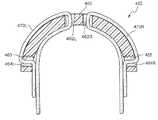
図2−1から図2−6に、本発明の実施形態による、左右対称の形で左側及び右側前額部ストラップを受け入れるように構成された前額部部材を備える前額部支持体が示されている。すなわち、前額部部材の各側(すなわち、前額部部材の右手側及び左手側の両方)が、左右対称のストラップが前額部部材を通ってループし更に各ストラップの第1のループがマスクの左右対称の垂直面に近傍の穴を通るように構成される。2.1 Symmetrical Straps FIGS. 2-1 to 2-6 include forehead members configured to receive left and right forehead straps in a symmetrical manner, according to embodiments of the present invention. A forehead support is shown. That is, each side of the forehead member (ie, both the right hand side and the left hand side of the forehead member) loops a symmetrical strap through the forehead member, and the first loop of each strap The mask is configured so as to pass through a hole in the vicinity of a symmetrical vertical plane of the mask.
以下の実施形態で示すように、各ストラップまたはストラップループは、前額部部材または前額部支持体を1回、2回、または3回以上通過することができ、それによりストラップが安定した形で固定される。 As shown in the following embodiments, each strap or strap loop can pass through the forehead member or forehead support once, twice, or more than three times so that the strap is in a stable shape. It is fixed with.
また、以下の実施形態では、前額部支持体は剛性であっても或いは柔軟性を有してもよく、各実施形態に異なる利点/欠点をもたらす。 Also, in the following embodiments, the forehead support may be rigid or flexible, resulting in different advantages / disadvantages for each embodiment.
2.1.1単一ループ−ヴェルクロ(Velcro(登録商標))
図2−1に、本発明の一実施形態による前額部支持体50を示す。前額部支持体50は前額部部材60を含み、前額部部材60の各側は、左右対称の垂直面55の近傍に穴または開口を含む(すなわち、前額部部材の左側の穴62L及び右側の穴62R)。示すように、左側及び右側のヘッドギアストラップ70L、70Rは左右対称の垂直面に近傍のそれぞれの穴62L及び62Rを通ってループしており、それにより、左側及び右側のヘッドギアストラップ70L、70Rが支持領域の大部分を覆うようになる。2.1.1 Single Loop-Velcro (Velcro®)
2-1 shows the
すなわち、各ヘッドギアストラップ70L、70Rは、端部領域にループ72L、72Rを形成し、これらのループは使用時には隣接して向かい合う関係となる。各ループ72L、72Rは、ヴェルクロ(Velcro(登録商標))アタッチメント80によって固定されるか或いは閉じられてよく、これにより長さの調節が可能となる。しかし、各ループは、例えば、縫成、バックル等といった他の適当な構成で閉じられてもよい。 That is, the headgear straps 70L and
示すように、各ループ72L、72Rは、前額部部材の内側表面に隣接する(患者の顔と向かって面している)内側74と、前額部部材の外側表面に隣接する(患者の顔から離れた側を向いている)外側76とを含む。内側表面に沿ったループの内側74は、患者の前額部と前額部支持体との間にヘッドギアの層を形成し、これは、使用時に患者の快適さを向上させる詰め物として機能する。具体的には、ヘッドギアの張力下で、ヘッドギアの詰め物が、圧力の高い接触領域が形成されるのを回避するために前額部の大部分にわたって荷重を分配し、触れると柔らかく且つ/または温かい接触領域を形成し、前額部の可能な限り広い部分を前額部支持体と確実に接触させて平均圧力が低下するように、前額部支持体と患者の前額部との間に柔らかく変形可能な中間物を介在させる。 As shown, each
一実施形態では、1つまたは複数の位置決めリブまたはリムを前額部支持体の前額部部材の長手方向に沿って設けて、ヘッドギアストラップと前額部支持体との間の相対的な位置ずれを防止すること、例えば、相対的な位置ずれを引き起こす可能性があり前額部支持体を患者の前額部に接触させる可能性がある、シート面に対して垂直の方向(すなわち、上方−下方平面の方向(すなわち、位置ずれは、前額部支持体の上方または下方へヘッドギアストラップが移動すること、それによって下にある剛性支持体材が露出することに起因する))に沿ったそれらのストラップと前額部支持体との間の相対的な動きを防止することができる。例えば、図2−1−1に示すように、前額部部材60の上方縁及び下方縁が、ヘッドギアストラップ70を受けるためのチャネルを形成してストラップの摺動を誘導する位置決めリム63をその長手方向に沿って備えてよい。 In one embodiment, one or more positioning ribs or rims are provided along the longitudinal direction of the forehead member of the forehead support to provide a relative position between the headgear strap and the forehead support. Preventing misalignment, for example, in a direction perpendicular to the seat surface (ie upward) that may cause relative misalignment and may cause the forehead support to contact the patient's forehead -Along the direction of the lower plane (ie due to displacement of the headgear strap above or below the forehead support, thereby exposing the underlying rigid support material) Relative movement between the straps and the forehead support can be prevented. For example, as shown in FIG. 2-1-1, an upper edge and a lower edge of the
2.1.2内側からの二重ループ−ヴェルクロ(Velcro(登録商標))
図2−2に、本発明の別の実施形態による前額部支持体250を示す。この実施形態では、前額部部材260の各側が、左右対称の垂直面255に近傍の第1の内側穴262L、262Rと、部材のそれぞれの端部に近傍の第2の外側穴264L、264Rとを含む。示すように、左側及び右側ヘッドギアストラップ270L、270Rはそれぞれ、左右対称の垂直面に近傍の個別の内側穴262L、262Rを通ってループし、それにより、ストラップ自体が支持領域の大部分を覆うようになる。また、各ストラップ270L、270Rは外側穴264L、264Rを通って戻るようにループし、それにより、ストラップと前額部支持体との間のいかなる位置ずれも防止される。ストラップによって形成される各ループ272L、272Rは、ヴェルクロ(Velcro(登録商標))アタッチメント280によって固定されてよい。示すように、各ストラップ270L、270Rは前額部支持体の内側に向かって戻るようにループし、ヴェルクロ(Velcro(登録商標))アタッチメント280が内側に沿って配置される。2.1.2 Double loop from inside-Velcro (R)
FIG. 2-2 shows a
2.1.3外側からの二重ループ−ヴェルクロ(Velcro(登録商標))
図2−3に、本発明の別の実施形態による前額部支持体350を示す。この実施形態では、前額部部材360の各側が、左右対称の垂直面355に近傍の第1の内側穴362L、362Rと、部材のそれぞれの端部に近傍の第2の外側穴364L、364Rとを含む。示すように、各ヘッドギアストラップ370L、370Rは、それぞれの第2の穴362L、362Rを通って戻るようにループする。ストラップによって形成される各ループ372L、372Rは、ヴェルクロ(Velcro(登録商標))アタッチメント380によって固定されてよい。示すように、各ストラップ370L、370Rは前額部支持体の外側に向かって戻るようにループし、ヴェルクロ(Velcro(登録商標))アタッチメント380が外側に沿って配置される。2.1.3 Double loop from outside-Velcro (R)
2-3 shows a
2.1.4内側からの二重ループ−バックル
図2−4に、本発明の別の実施形態による前額部支持体450を示す。この実施形態は図2−2に類似しており、ストラップ470L、470Rが前額部部材460のそれぞれの第1の穴462L、462R及び第2の穴464L、464Rを通ってループしており、前額部支持体の内側に向かって戻るようにループしている。異なるのは、各ストラップ470L、470Rが、前額部支持体をバックルとして使用して固定されており、それによりヘッドギアの製造プロセスが簡略化され、より安価になることである。例えば、各第2の穴464L、464Rは、それぞれのストラップを所定の位置に固定するように構成された1つまたは複数の歯465を含んでよい(例えば、ヘッドギアバックル内でのラダーロック構成)。2.1.4 Double Loop from Inside-Buckle FIG. 2-4 illustrates a
2.1.5二重の詰め物を用いた単一バックル
図2−5に、本発明の別の実施形態による前額部支持体550を示す。この実施形態では、前額部部材560の各側が、左右対称の垂直面555の近傍に対となる穴562(1)L、562(2)L、562(1)R、562(2)Rを含む。示すように、各ヘッドギアストラップ570L、570Rは、穴562(1)、562(2)L、562(1)R、562(2)Rのそれぞれの対を通って戻るようにループし、それにより、両側のループ572L、572Rが前額部部材の内側表面に沿って(患者の顔に向かって面して)延在する。この構成により、患者の前額部と前額部支持体との間に挿置される二重の層のヘッドギアが形成され、使用時における詰め物の効果が向上する。2.1.5 Single buckle with double padding FIG. 2-5 illustrates a
図2−4と同様に、各ストラップ570L、570Rは前額部支持体560をバックルとして使用することにより固定されてよい。図2−1に関連して上述したように、1つまたは複数の位置決めリムが、安定性を向上させヘッドギアストラップと前額部支持体との間の相対的な位置ずれを防止するために、前額部支持体の前額部部材の長手方向に沿って設けられてよい。 Similar to FIGS. 2-4, each
2.1.6二重の詰め物を用いた複数ループ
図2−6に、本発明の別の実施形態による前額部支持体650を示す。この実施形態では、前額部部材660の各側が、左右対称の垂直面655の近傍に対となる内側穴662(1)L、662(2)L、662(1)R、662(2)R、及び、部材のそれぞれの端部の近傍に対となる外側穴664(1)L、664(2)L、664(1)R、664(2)Rを含む。示すように、各ヘッドギアストラップ670L、670Rは、外側の穴664(1)L、664(1)Rのうちのそれぞれの1つを通過し(外側から内側へ)、それぞれの内側穴662(1)L、662(2)L、662(1)R、662(2)Rを通ってループし、次いで、前額部支持体の外側に向かって戻るように残りの外側穴664(2)L、664(2)Rを通過する(内側から外側へ)。2.1.6 Multiple loops with double padding FIGS. 2-6 illustrate a
ストラップは、使用時における詰め物の効果を向上させるために患者の前額部と前額部支持体との間に挿置される二重の層のヘッドギアを形成する形で複数回ループする。更に、前額部支持体は、安定性を向上させヘッドギアストラップと前額部支持体との間の相対的な位置ずれを防止する形でストラップを維持する。 The strap loops multiple times to form a double layer headgear that is inserted between the patient's forehead and forehead support to improve the effectiveness of the padding in use. In addition, the forehead support maintains the strap in a manner that improves stability and prevents relative misalignment between the headgear strap and the forehead support.
各ループは、ヴェルクロ(Velcro(登録商標))アタッチメントを用いて或いは図2−4及び図2−5のようにバックル装置を用いて固定されてよい。 Each loop may be secured using a Velcro (R) attachment or using a buckle device as in FIGS. 2-4 and 2-5.
2.2非対称のストラップ
図2−7から図2−9に、ヘッドギアストラップが左右対称の垂直面を基準に左右対称でない穴をループしている、前額部支持体の実施形態が示されている。2.2 Asymmetric straps FIGS. 2-7 to 2-9 show an embodiment of the forehead support in which the headgear strap loops through a non-symmetrical hole with respect to a symmetrical vertical plane. Yes.
以下の実施形態では、前額部支持体は剛性であっても或いは柔軟性を有してもよく、各実施形態に異なる利点/欠点をもたらす。 In the following embodiments, the forehead support may be rigid or flexible, resulting in different advantages / disadvantages for each embodiment.
2.2.1内側からの二重ループ
図2−7に、本発明の一実施形態による前額部支持体750を示す。前額部支持体750は、部材の一方の端部(例えば、図2−7に示すように左側)に隣接した第1の小さい穴762と部材の他方の端部(例えば、図2−7に示すように右側)に隣接した第2の大きい穴764とを含む前額部部材760を含む。2.2.1 Double Loop from Inside FIG. 2-7 illustrates a
示すように、より長い左側のヘッドギアストラップ770Lは、第1及び第2の穴726、764を通ってループし、前額部支持体の内側に向かって戻るようにループする。より長い左側のヘッドギアストラップ770Lは、ヴェルクロ(Velcro(登録商標))アタッチメント780を用いて或いはバックル装置を用いて固定されてよい。より短い右側のヘッドギアストラップ770Rは第2の穴764を通ってループしており、ヴェルクロ(Velcro(登録商標))アタッチメント780を用いて或いはバックル装置を用いて固定されてよい。より長い左側のヘッドギアストラップ770Lは、患者の前額部と前額部支持体との間に挿置されるヘッドギアの層を形成する。 As shown, the longer left
2.2.2外側からの二重ループ
図2−8に、本発明の別の実施形態による前額部支持体850を示す。この実施形態は図2−7に類似しており、第1及び第2の穴862、864が前額部部材860のそれぞれの端部に隣接している。異なるのは、より長い左側の前額部ストラップ870Lが、前額部支持体の外側に向かって戻るようにループしていることである。左側のヘッドギアストラップ870Lは、ヴェルクロ(Velcro(登録商標))アタッチメント880を用いて或いはバックル装置を用いて固定されてよい。より短い右側のヘッドギアストラップ870Rは第2の穴864を通ってループしており、ヴェルクロ(Velcro(登録商標))アタッチメント880を用いて或いはバックル装置を用いて固定されてよい。2.2.2 Double Loop from Outside FIG. 2-8 illustrates a
2.2.3追加のバックルを用いたループ
図2−9に、本発明の別の実施形態による前額部支持体950を示す。前額部支持体950は、部材の一方の端部に隣接した第1の穴962と部材の他方の端部に隣接した第2の穴964とを含む前額部部材960を含む。示すように、より長い左側のヘッドギアストラップ970Lは、第1の穴962を通ってループし(外側から内側へ)、前額部支持体の内側表面に沿って移動し、ストラップの自由端が前額部支持体の外側から延在するように第2の穴964を通ってループする(内側から外側へ)。2.2.3 Loop with Additional Buckle FIG. 2-9 illustrates a
従って、より長い左側のヘッドギアストラップ970Lは患者の前額部及び前額部支持体の全周囲をループし、例えばバックル980またはヴェルクロ(Velcro(登録商標))アタッチメントを通して、より短い右側のヘッドギアストラップ970Rに連結される。左側の前額部ストラップ970Lは、例えば引張り効果を生み出すために第1及び第2の支持穴962、964の内側に自由に摺動することができる。 Thus, the longer left
2.3引張り効果
ヘッドギアストラップの張力は、ストラップが患者の前額部と前額部支持体との間で押圧されたときにストラップ自体の圧縮に付加的なばね効果を生み出すことができる。これは、患者の前額部上に前額部支持体を付勢するのに有利である可能性があり、それにより、マスクの密封状態が向上する。加えて、このばね効果によりヘッドギアストラップが患者の頭のサイズに適合するようになることから、調節機構(例えば、バックル)の必要性をなくすことができる。2.3 Tensile Effect The tension of the headgear strap can create an additional spring effect on the compression of the strap itself when the strap is pressed between the patient's forehead and the forehead support. This can be advantageous for biasing the forehead support over the patient's forehead, thereby improving the sealing of the mask. In addition, the spring effect allows the headgear strap to fit the size of the patient's head, thus eliminating the need for an adjustment mechanism (eg, a buckle).
ばね効果は非対称の構成においてより明白となるが、左右対称の構成に対しても有効であり、すなわち、ばね効果の大きさは使用される幾何形状に応じてよい。例えば、図2−10に、図2−9に示した前額部支持体と類似しており同様の参照符号で示されている前額部支持体950が示されている。図示したように、ヘッドギアストラップ970Lは、ストラップを張力下に置くための穴962、964の間で伸びることができ、使用時にヘッドギアストラップがばね効果を生み出すのを可能にする。ストラップ970Lの緊縮性は、ばね効果を調整するために調節することができる。 The spring effect becomes more apparent in an asymmetric configuration, but is also effective for a symmetric configuration, i.e. the magnitude of the spring effect may depend on the geometry used. For example, FIG. 2-10 shows a
2.4ストラップの取外し
前額部部材の各穴またはスロットは、ヴェルクロ(Velcro(登録商標))アタッチメントを外すことなく、また例えばヘッドギアの正常な長さを減少させることなくヘッドギアストラップが固定されるのを可能にするギャップまたは開口側を含んでよい。2.4 Removal of thestrap Each hole or slot in the forehead member secures the headgear strap without removing the Velcro® attachment and without reducing the normal length of the headgear, for example. It may include a gap or open side that allows
例えば、図2−11に、第1及び第2のスロット1062、1064を含んだ前額部部材1060の一方の側が示されており、第1のスロット1062はその上側縁に沿って開口側1066を含んでおり、第2のスロット1064はその右側縁に沿って開口側1068を含んでいる。示すように、第1のスロット1062用の開口側1066は、ストラップの不適切な分離を防止するためにL形である。この構成により、ヴェルクロ(Velcro(登録商標))を用いて固定されたストラップが、ヴェルクロ(Velcro(登録商標))自体を実際に開けることなく、従ってヘッドギアの設定を無効にすることなく、前額部支持体から取り外されることが可能になる。この構成は、ヘッドギアを洗浄する必要があってその後に適切な密封状態を実現するためにヘッドギアを再度設定することによる時間の損失を回避する際にかなり有効である。すなわち、この構成は、ヘッドギア支持体からのヘッドギアストラップの組立て及び取外しを容易にする。 For example, FIG. 2-11 shows one side of the
このような即時に解除できる構成は、バックルを用いて固定されたストラップと共に使用されてもよく、例えば、レスメッドホスピタル(ResMed Hospital)フルフェイスマスクの即時に解除できるバックル構成が使用されてよい。 Such an instant release configuration may be used with a strap secured with a buckle, for example, an immediate release buckle configuration of a ResMed Hospital full face mask may be used.
2.5他の構成
以下に前額部支持体の代替の構成を示す。2.5 Other configurations Below are alternativeconfigurations of the forehead support.
2.5.1ヴェルクロ(Velcro(登録商標))を用いた前額部支持体
上述したように、ヘッドギアの上側ストラップは、ヴェルクロ(Velcro(登録商標))を用いて前額部支持体に取り付けることができる。ストラップは使用時において柔らかい詰め物として機能し、ヴェルクロ(Velcro(登録商標))はストラップを安定させる。2.5.1 Forehead Support Using Velcro® As described above, the upper strap of the headgear is attached to the forehead support using Velcro®. be able to. The strap functions as a soft padding when in use and Velcro® stabilizes the strap.
2.5.2パッドとしてのヘッドギアクリップ
一実施形態では、ヘッドギアの上側ストラップは、ヘッドギアクリップ装置、すなわち、前額部支持体に設けられたクリップ受けと着脱自在にインターロックするように適合された個別のヘッドギアストラップと連動するヘッドギアクリップを介して前額部支持体に連結されてよい。2.5.2 Headgear Clip as Pad In one embodiment, the upper strap of the headgear is adapted to detachably interlock with a headgear clip device, i.e., a clip receiver provided on the forehead support. It may be connected to the forehead support via a headgear clip that interlocks with individual headgear straps.
この実施形態は、左右対称ストラップの実施形態(例えば、図2−1から図2−6)と同様に機能するが、ストラップは、前額部支持体の周りを直接ループする代わりにクリップに連結される。クリップは上述した左右対称面の近傍で前額部支持体に連結され、適切な前額部支持体として機能する。クリップは、使用時に患者の前額部と係合する適合された内側表面に沿った詰め物を含んでよい。 This embodiment functions similarly to the symmetric strap embodiments (eg, FIGS. 2-1 to 2-6), but the strap is connected to the clip instead of looping directly around the forehead support. Is done. The clip is connected to the forehead support in the vicinity of the above-described plane of symmetry and functions as a suitable forehead support. The clip may include a padding along the adapted inner surface that engages the patient's forehead in use.
2.5.3前額部支持体上の位置決めリブ
上述したように、1つまたは複数の位置決めリムが、ストラップが摺動するチャネルを形成するために前額部部材の長手方向に沿って設けられる(図2−1−1)。快適性を向上させるため、リムは、例えばストラップの過剰な圧縮により患者の前額部に偶然に接触することがないように、前額部支持体の外側表面に配置されてよい。2.5.3 Positioning ribs on the forehead support As described above, one or more positioning rims are provided along the length of the forehead member to form a channel through which the strap slides. (FIG. 2-1-1). To improve comfort, the rim may be placed on the outer surface of the forehead support so that it does not accidentally contact the patient's forehead due to, for example, excessive compression of the strap.
2.5.4切断されたストラップ
一実施形態では、ヘッドギアの各上側ストラップはその長手軸に沿って切断されてよく、或いはそうでない場合は、図2−12に示すように、離隔された一対のストラップ1170、1171を形成するように作られてもよい。すなわち、各上側ストラップは、上述した方式と同様の方式でループして前額部支持体1150に固定される端部を有する2つの離隔されたストラップ1170、1171に分岐してよい。例えば、非対称構成(例えば、図2−7から図2−9)のより長いストラップは、患者の前額部の輪郭により適合するようにその長手軸に沿って切断されてよい。有利には、これにより、患者の前額部上でより安定したストラップの接合が実現される。2.5.4 Cut Strap In one embodiment, each upper strap of the headgear may be cut along its longitudinal axis, or otherwise, as shown in FIG. The
2.5.5前額部梁
一実施形態では、前額支持体は、例えばストラップが通過してループするのにちょうど適当であるように最小寸法であってよい。この実施形態では、可撓性梁が、ヘッドギアストラップにより前額部支持体と一体に結び付けられてよい。使用時に、ストラップが患者の前額部に接触し、梁がその剛性に応じて荷重を分配する。2.5.5 Forehead Beam In one embodiment, the forehead support may be minimally dimensioned, for example, just suitable for a strap to pass through and loop. In this embodiment, the flexible beam may be tied together with the forehead support by a headgear strap. In use, the strap contacts the patient's forehead and the beam distributes the load according to its stiffness.
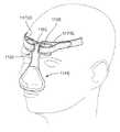
例えば、図2−13A及び図2−13Bに、開口部1162L、1162Rに対して十分である狭い幅を有する前額部部材1160を備える前額部支持体1150を含むマスク1145が示されている。開口部1192L、1192Rを備える可撓性梁1190は、前額部部材1160の開口部1162L、1162Rに位置合わせされ、ヘッドギアストラップ1170L、1170Rを介してそれらと結合される。具体的には、各ヘッドギアストラップ1170L、1170Rは、前額部部材1160及び梁1190のそれぞれの開口1162L、1162R、1192L、1192Rを通ってループし、このループは、ヴェルクロ(Velcro(登録商標))アタッチメント1180を用いて固定されてよい。梁1190の内側表面に沿ったループの内側は、患者の前額部と前額部支持体との間にヘッドギアの層を形成し、これは使用時に詰め物として機能する。 For example, FIGS. 2-13A and 2-13B illustrate a
梁1190は追加の構成要素であるため、その材料及び剛性は、マスクのマスクレーム及び前額部支持体の材料及び剛性とは別に選択することができる。例えば、種々のサイズ、材料及び/または剛性値の梁が使用されてよく、使用時に適切な荷重分配を実現する。 Since
本発明を、現時点で最も実用的で好ましい実施形態と思われるものに関連して説明してきたが、本発明は、開示した実施形態に限定されるものではなく、逆に、本発明の精神及び範囲に含まれる様々な修正形態及び均等の構成を包含するものであることを理解されたい。また、上述の様々な実施形態を、他の実施形態と合わせて実施してもよく、例えば、ある実施形態の態様を別の実施形態の態様と組み合わせて更なる別の実施形態を実現してもよい。更にまた、任意の所与の組立体の各別個の特徴または構成要素は、追加の実施形態を構成することができる。更に、本発明は閉塞型睡眠時無呼吸(OSA:obstructive sleep apnea)を患う患者に特に適用されるが、他の病気(例えば、うっ血性心不全、糖尿病、病的肥満、脳卒中、肥満症治療手術等)を患う患者も、上記の教示から利益を得ることができることを理解されたい。更に、上記の教示は、医療以外の用途で、患者にも患者でない人にも適用することができる。 Although the present invention has been described in connection with what is presently considered to be the most practical and preferred embodiments, the present invention is not limited to the disclosed embodiments, and conversely, the spirit and It should be understood that various modifications and equivalent configurations included in the scope are included. Also, the various embodiments described above may be implemented in combination with other embodiments, for example, by combining aspects of one embodiment with aspects of another embodiment to achieve further embodiments. Also good. Furthermore, each distinct feature or component of any given assembly may constitute an additional embodiment. Furthermore, the present invention is particularly applicable to patients suffering from obstructive sleep apnea (OSA), but other diseases (eg congestive heart failure, diabetes, morbid obesity, stroke, bariatric surgery) It should be understood that patients suffering from etc. may also benefit from the above teachings. Furthermore, the above teachings can be applied to non-patients and non-patients for non-medical applications.
10 マスク
12 フレーム
14 クッション
16 エルボー
18、50、250、350、450、550、650、750、850、950、1150 前額部支持体
18(1) 基部
18(2) アーム
20 前額部パッド
22 スロット
55、255、355、555、655 垂直面
60、260、360、460、560、660、760、860、960、1060、1160 前額部部材
62L、62R、262L、262R、264L、264R、362L、362R、364L、364R、462L、462R、464L、464R、562(1)L、562(2)L、562(1)R、562(2)R、662(1)L、662(2)L、662(1)R、662(2)R、664(1)L、664(2)L、664(1)R、664(2)R、762、764、862、864、962、964 穴
63 位置決めリム
70、70L、70R、270L、270R、370L、370R、470L、470R、570L、570R、670L、670R、770L、770R、870L、870R、970L、970R、1170L、1170R ヘッドギアストラップ
72L、72R、272L、272R、372L、372R、572L、572R ループ
74 内側
76 外側
80、280、380、780、880、1180 ヴェルクロ(Velcro(登録商標))アタッチメント
465 歯
980 バックル
1062、1064 スロット
1066、1068 開口側
1145 マスク
1162L、1162R、1192L、1192R 開口部
1170、1171 離隔されたストラップ
1190 可撓性梁10 Mask 12 Frame 14 Cushion 16 Elbow 18, 50, 250, 350, 450, 550, 650, 750, 850, 950, 1150 Forehead Support 18 (1) Base 18 (2) Arm 20 Forehead Pad 22 Slot 55, 255, 355, 555, 655 Vertical plane 60, 260, 360, 460, 560, 660, 760, 860, 960, 1060, 1160 Forehead member 62L, 62R, 262L, 262R, 264L, 264R, 362L , 362R, 364L, 364R, 462L, 462R, 464L, 464R, 562 (1) L, 562 (2) L, 562 (1) R, 562 (2) R, 662 (1) L, 662 (2) L , 662 (1) R, 662 (2) R, 664 (1) L, 664 (2) L, 664 (1) R , 664 (2) R, 762, 764, 862, 864, 962, 964 hole 63 positioning rim 70, 70L, 70R, 270L, 270R, 370L, 370R, 470L, 470R, 570L, 570R, 670L, 670R, 770L, 770R, 870L, 870R, 970L, 970R, 1170L, 1170R Headgear Strap 72L, 72R, 272L, 272R, 372L, 372R, 572L, 572R Loop 74 Inner 76 Outer 80, 280, 380, 780, 880, 1180 Velcro (Velcro ( (Registered trademark)) Attachment 465 Teeth 980 Buckle 1062, 1064 Slot 1066, 1068 Open side 1145 Mask 1162L, 1162R, 1192L, 1192R Opening 1170, 1171 Septum straps 1190 flexible beam
Claims (13)
Translated fromJapanese該マスクフレームに設けられ、前額部部材を含む前額部支持体と、
前記前額部部材に連結されるように適合された少なくとも1つのストラップを含むヘッドギアと、
を備え、
前記前額部部材が、少なくとも1つのストラップが該前額部部材の少なくとも一部分の周りをループするストラップループを形成し、使用時に前記ヘッドギア部材と患者の前額部との間に1つまたは複数の層のストラップループを構成するのを可能にするように構成及び配置される1つまたは複数の穴を含む、
呼吸マスク。Mask frame,
A forehead support provided on the mask frame and including a forehead member;
Headgear including at least one strap adapted to be coupled to the forehead member;
With
The forehead member forms a strap loop in which at least one strap loops around at least a portion of the forehead member, and in use, one or more between the headgear member and the patient's forehead Including one or more holes configured and arranged to allow for the formation of strap loops of layers of
Breathing mask.
該マスクフレームに設けられ、前額部部材を含む前額部支持体と、
第1及び第2のストラップを含むヘッドギアと、
を備え、
前記前額部部材が、前記第1及び第2のストラップが該前額部部材の個別の部分の周りをループする第1及び第2のストラップループを形成するのを可能にするように構成及び配置される1つまたは複数の穴を含み、前記ストラップループが、前記前額部部材の左右対称の垂直面を基準に非対称に配置される、
呼吸マスク。Mask frame,
A forehead support provided on the mask frame and including a forehead member;
A headgear including first and second straps;
With
The forehead member is configured to allow the first and second straps to form first and second strap loops that loop around separate portions of the forehead member; and Including one or more holes to be disposed, wherein the strap loop is disposed asymmetrically with respect to a symmetrical vertical plane of the forehead member;
Breathing mask.
該マスクフレームに設けられ、第1の幅を有する前額部部材を含む前額部支持体と、
前記第1の幅より大きい第2の幅を含む可撓性梁と、
第1及び第2のストラップを含むヘッドギアと、
を備え、
前記前額部部材及び前記可撓性梁がそれぞれ、前記第1及び第2のストラップが該前額部部材及び該可撓性梁の個別の部分の周りをループする第1及び第2のストラップループを形成するのを可能にするように構成及び配置される開口部を含み、各ストラップループの層が、使用時に前記可撓性梁と患者の前額部との接触を防止するために前記可撓性梁と患者の前額部との間に配置される、
呼吸マスク。Mask frame,
A forehead support provided on the mask frame and including a forehead member having a first width;
A flexible beam including a second width greater than the first width;
A headgear including first and second straps;
With
The forehead member and the flexible beam are respectively first and second straps wherein the first and second straps loop around separate portions of the forehead member and the flexible beam, respectively. Including openings configured and arranged to allow a loop to be formed, wherein each strap loop layer is configured to prevent contact between the flexible beam and a patient's forehead in use. Located between the flexible beam and the patient's forehead,
Breathing mask.
該マスクフレームに設けられる前額部支持体と、
該前額部支持体に連結されるように適合された少なくとも1つのストラップを含むヘッドギアと、
を備え、
前記少なくとも1つのストラップが、前記前額部支持体と患者の前額部との間に離隔されたストラップのそれぞれの層を配置するために前記前額部支持体の少なくとも一部分の周りをループする2つの離隔されたストラップに分岐する、
呼吸マスク。Mask frame,
A forehead support provided on the mask frame;
Headgear including at least one strap adapted to be coupled to the forehead support;
With
The at least one strap loops around at least a portion of the forehead support to position respective layers of the strap spaced between the forehead support and the patient's forehead. Branch into two spaced straps,
Breathing mask.
Applications Claiming Priority (2)
| Application Number | Priority Date | Filing Date | Title |
|---|---|---|---|
| AU2007903361 | 2007-06-22 | ||
| AU2007903361AAU2007903361A0 (en) | 2007-06-22 | Forehead Support for a Facial Mask |
Publications (3)
| Publication Number | Publication Date |
|---|---|
| JP2009000532Atrue JP2009000532A (en) | 2009-01-08 |
| JP2009000532A5 JP2009000532A5 (en) | 2011-06-30 |
| JP5542314B2 JP5542314B2 (en) | 2014-07-09 |
Family
ID=39712638
Family Applications (1)
| Application Number | Title | Priority Date | Filing Date |
|---|---|---|---|
| JP2008162512AExpired - Fee RelatedJP5542314B2 (en) | 2007-06-22 | 2008-06-20 | Breathing mask |
Country Status (6)
| Country | Link |
|---|---|
| US (1) | US9061113B2 (en) |
| EP (1) | EP2005987B1 (en) |
| JP (1) | JP5542314B2 (en) |
| CN (1) | CN101327354B (en) |
| ES (1) | ES2464283T3 (en) |
| NZ (3) | NZ582624A (en) |
Cited By (2)
| Publication number | Priority date | Publication date | Assignee | Title |
|---|---|---|---|---|
| JP2020006164A (en)* | 2018-07-02 | 2020-01-16 | ▲や▼博股▲ふん▼有限公司Apex Medical Corp. | Patient interface with adaptation system, respiratory mask and pad for the adaptation system |
| JP2022036184A (en)* | 2009-11-20 | 2022-03-04 | レスメド・プロプライエタリー・リミテッド | Mask system |
Families Citing this family (24)
| Publication number | Priority date | Publication date | Assignee | Title |
|---|---|---|---|---|
| DE20017940U1 (en) | 2000-10-19 | 2000-12-28 | MAP Medizintechnik für Arzt und Patient GmbH & Co KG, 82152 Planegg | Breathing mask for supplying a breathing gas to a mask user and a derivation device for deriving breathing gas |
| US7320323B2 (en) | 2001-10-22 | 2008-01-22 | Map Medizin-Technologie Gmbh | Breathing mask device and application device and frontal support device thereof |
| DE10201682A1 (en) | 2002-01-17 | 2003-07-31 | Map Medizin Technologie Gmbh | The breathing mask arrangement |
| DE10151984C5 (en) | 2001-10-22 | 2008-07-17 | Map Medizin-Technologie Gmbh | Application device for a breathing mask arrangement |
| ES2443417T3 (en) | 2002-09-06 | 2014-02-19 | Resmed Limited | Forehead pad for a respiratory mask |
| CN101987221B (en) | 2003-05-02 | 2013-09-04 | 雷斯梅德有限公司 | A mask system |
| US8397728B2 (en) | 2005-10-14 | 2013-03-19 | Resmed Limited | Cushion to frame assembly mechanism |
| US20090126739A1 (en) | 2005-10-25 | 2009-05-21 | Resmed Limited | Interchangeable Mask Assembly |
| USD586458S1 (en)* | 2006-04-07 | 2009-02-10 | Resmed Limited | Respiratory mask |
| US8517023B2 (en) | 2007-01-30 | 2013-08-27 | Resmed Limited | Mask system with interchangeable headgear connectors |
| US11331447B2 (en) | 2008-03-04 | 2022-05-17 | ResMed Pty Ltd | Mask system with snap-fit shroud |
| NZ783425A (en) | 2008-03-04 | 2022-12-23 | ResMed Pty Ltd | Mask system |
| US8967148B2 (en) | 2009-05-18 | 2015-03-03 | Weinmann Gerate Fur Medizin Gmbh & Co. Kg | Respiratory device comprising a fastening system |
| US9149593B2 (en) | 2009-05-29 | 2015-10-06 | Resmed Limited | Nasal mask system |
| AU2013257413B2 (en)* | 2009-05-29 | 2015-03-19 | ResMed Pty Ltd | Nasal Mask System |
| USD679799S1 (en) | 2010-01-08 | 2013-04-09 | Resmed Limited | Mask assembly |
| CN102284118A (en)* | 2011-05-30 | 2011-12-21 | 牛红丽 | Novel noninvasive ventilation mask |
| WO2013056389A1 (en)* | 2011-10-18 | 2013-04-25 | Honeywell International Inc. | Automatically adjustable cushion of respiratory mask for better fit |
| KR102662489B1 (en) | 2015-03-31 | 2024-05-02 | 피셔 앤 페이켈 핼스케어 리미티드 | User interface and system for gassing the airway |
| US10188177B2 (en)* | 2015-08-17 | 2019-01-29 | Bell Sports, Inc. | Friction stop strap adjustor |
| EP3995168B8 (en) | 2016-08-11 | 2025-09-03 | Fisher & Paykel Healthcare Limited | A collapsible conduit, patient interface and headgear connector |
| USD856510S1 (en) | 2018-01-29 | 2019-08-13 | Fisher & Paykel Healthcare Limited | Combined elbow and swivel with a rotatable pressure port |
| FR3106498A1 (en) | 2020-01-27 | 2021-07-30 | L'Air Liquide Société Anonyme pour l'Etude et l'Exploitation des Procédés Georges Claude | Respirator mask with system for measuring the effective duration of inhaled therapy |
| FR3106982B1 (en) | 2020-02-11 | 2022-01-14 | Air Liquide | Gas supply assembly with system for measuring the effective duration of an inhaled therapy |
Citations (7)
| Publication number | Priority date | Publication date | Assignee | Title |
|---|---|---|---|---|
| WO2003082406A2 (en)* | 2002-03-22 | 2003-10-09 | Invacare Corporation | Nasal mask |
| WO2005002656A1 (en)* | 2003-06-23 | 2005-01-13 | Invacare Corporation | Nasal mask |
| WO2005009521A1 (en)* | 2003-07-30 | 2005-02-03 | Fisher & Paykel Healthcare Limited | Forehead rest for respiratory masks |
| US20050268916A1 (en)* | 2004-05-18 | 2005-12-08 | Mumford John R | Mask assembly with integrated sensors |
| WO2005123166A1 (en)* | 2004-06-16 | 2005-12-29 | Resmed Limited | Cushion for a respiratory mask assembly |
| JP2006506109A (en)* | 2002-09-06 | 2006-02-23 | アールアイシー・インベストメンツ・インコーポレイテッド | Patient interface material with forehead support device |
| WO2006113321A2 (en)* | 2005-04-13 | 2006-10-26 | Ric Investments, Llc | Cushion inside a cushion patient interface |
Family Cites Families (21)
| Publication number | Priority date | Publication date | Assignee | Title |
|---|---|---|---|---|
| US858694A (en) | 1906-08-24 | 1907-07-02 | Olof Winkler | Combined collar-button and necktie-fastener. |
| US4621378A (en)* | 1984-05-23 | 1986-11-11 | Hatchman Robert A | Eyeshield |
| US4825878A (en)* | 1987-12-28 | 1989-05-02 | Kuntz David H | Light-weight disposable protective face shield |
| US5074297A (en)* | 1989-12-19 | 1991-12-24 | The General Hospital Corporation | Self-sealing mask for delivering intermittent positive pressure ventilation |
| FR2707504B1 (en)* | 1993-07-13 | 1995-09-29 | Jacobelli Chantal Michele Andr | Oral respiratory mask. |
| AUPM338394A0 (en)* | 1994-01-17 | 1994-02-10 | Moorhouse, Gerard Maxwell | Impact resistant screen |
| AUPO126596A0 (en)* | 1996-07-26 | 1996-08-22 | Resmed Limited | A nasal mask and mask cushion therefor |
| AUPO399596A0 (en)* | 1996-12-02 | 1997-01-02 | Resmed Limited | A harness assembly for a nasal mask |
| AUPQ104099A0 (en)* | 1999-06-18 | 1999-07-08 | Resmed Limited | Forehead support for facial mask |
| US6119693A (en)* | 1998-01-16 | 2000-09-19 | Resmed Limited | Forehead support for facial mask |
| AUPQ821500A0 (en)* | 2000-06-19 | 2000-07-13 | Australian Centre For Advanced Medical Technology Ltd | Mask |
| AU2002301370B2 (en)* | 2001-09-07 | 2008-09-25 | Resmed Limited | Mask Assembly |
| US6805117B1 (en)* | 2001-11-07 | 2004-10-19 | Ric Investments, Llc | Universal fitting headgear |
| AUPS192602A0 (en) | 2002-04-23 | 2002-05-30 | Resmed Limited | Nasal mask |
| ES2443417T3 (en)* | 2002-09-06 | 2014-02-19 | Resmed Limited | Forehead pad for a respiratory mask |
| US20040211428A1 (en)* | 2003-02-28 | 2004-10-28 | Sunrise Medical Hhg Inc. | Nasal mask cushion |
| US7047971B2 (en)* | 2003-10-03 | 2006-05-23 | Ric Investments, Llc. | Patient interface with forehead and chin support |
| US7296575B1 (en)* | 2003-12-05 | 2007-11-20 | Ric Investments, Llc | Headgear and interface assembly using same |
| US20060053658A1 (en)* | 2004-09-15 | 2006-03-16 | Dee Voughlohn | Unique systems and methods for fastening footwear |
| DE202006021248U1 (en) | 2005-01-12 | 2014-02-13 | Resmed Limited | Forehead supports for face masks |
| TW201106999A (en)* | 2009-08-26 | 2011-03-01 | Hsiner Co Ltd | Breathing mask |
- 2008
- 2008-06-17NZNZ582624Apatent/NZ582624A/enunknown
- 2008-06-17NZNZ569153Apatent/NZ569153A/enunknown
- 2008-06-17NZNZ591863Apatent/NZ591863A/enunknown
- 2008-06-20JPJP2008162512Apatent/JP5542314B2/ennot_activeExpired - Fee Related
- 2008-06-20CNCN200810126987.6Apatent/CN101327354B/ennot_activeExpired - Fee Related
- 2008-06-20USUS12/213,584patent/US9061113B2/enactiveActive
- 2008-06-23ESES08158803.0Tpatent/ES2464283T3/enactiveActive
- 2008-06-23EPEP08158803.0Apatent/EP2005987B1/ennot_activeNot-in-force
Patent Citations (9)
| Publication number | Priority date | Publication date | Assignee | Title |
|---|---|---|---|---|
| WO2003082406A2 (en)* | 2002-03-22 | 2003-10-09 | Invacare Corporation | Nasal mask |
| JP2006506109A (en)* | 2002-09-06 | 2006-02-23 | アールアイシー・インベストメンツ・インコーポレイテッド | Patient interface material with forehead support device |
| WO2005002656A1 (en)* | 2003-06-23 | 2005-01-13 | Invacare Corporation | Nasal mask |
| WO2005009521A1 (en)* | 2003-07-30 | 2005-02-03 | Fisher & Paykel Healthcare Limited | Forehead rest for respiratory masks |
| US20050268916A1 (en)* | 2004-05-18 | 2005-12-08 | Mumford John R | Mask assembly with integrated sensors |
| WO2005123166A1 (en)* | 2004-06-16 | 2005-12-29 | Resmed Limited | Cushion for a respiratory mask assembly |
| JP2008502380A (en)* | 2004-06-16 | 2008-01-31 | レスメド リミテッド | Cushion for respirator assembly |
| WO2006113321A2 (en)* | 2005-04-13 | 2006-10-26 | Ric Investments, Llc | Cushion inside a cushion patient interface |
| JP2008536565A (en)* | 2005-04-13 | 2008-09-11 | アールアイシー・インベストメンツ・エルエルシー | Double buffer subject interface device |
Cited By (3)
| Publication number | Priority date | Publication date | Assignee | Title |
|---|---|---|---|---|
| JP2022036184A (en)* | 2009-11-20 | 2022-03-04 | レスメド・プロプライエタリー・リミテッド | Mask system |
| JP7293410B2 (en) | 2009-11-20 | 2023-06-19 | レスメド・プロプライエタリー・リミテッド | mask system |
| JP2020006164A (en)* | 2018-07-02 | 2020-01-16 | ▲や▼博股▲ふん▼有限公司Apex Medical Corp. | Patient interface with adaptation system, respiratory mask and pad for the adaptation system |
Also Published As
| Publication number | Publication date |
|---|---|
| EP2005987A3 (en) | 2009-03-25 |
| ES2464283T3 (en) | 2014-06-02 |
| US20080314389A1 (en) | 2008-12-25 |
| NZ591863A (en) | 2013-04-26 |
| JP5542314B2 (en) | 2014-07-09 |
| NZ569153A (en) | 2010-02-26 |
| NZ582624A (en) | 2011-08-26 |
| CN101327354B (en) | 2014-01-08 |
| EP2005987B1 (en) | 2014-04-30 |
| US9061113B2 (en) | 2015-06-23 |
| CN101327354A (en) | 2008-12-24 |
| EP2005987A2 (en) | 2008-12-24 |
Similar Documents
| Publication | Publication Date | Title |
|---|---|---|
| JP5542314B2 (en) | Breathing mask | |
| US20220001129A1 (en) | Foam respiratory mask | |
| US8286635B2 (en) | Headgear for mask assembly | |
| US8695601B2 (en) | Forehead support for a patient interface | |
| US11191918B2 (en) | Patient interface assembly with self-adjusting anchor points | |
| CN102512741B (en) | Headgear assembly for a mask system, forming method thereof and mask system | |
| JP5746635B2 (en) | Adjustable headgear | |
| JP6105291B2 (en) | Patient interface device with cheekbone stabilization | |
| US20140283841A1 (en) | Ergonomically formed headgear straps | |
| JP2016517758A (en) | Stabilized mask | |
| EP4221795B1 (en) | Soft slide-through mechanism for cpap headgear | |
| US12208210B2 (en) | Wrap-back headgear for patient interface | |
| JP2015506204A (en) | Headgear assembly with improved stabilization |
Legal Events
| Date | Code | Title | Description |
|---|---|---|---|
| A521 | Written amendment | Free format text:JAPANESE INTERMEDIATE CODE: A523 Effective date:20110516 | |
| A621 | Written request for application examination | Free format text:JAPANESE INTERMEDIATE CODE: A621 Effective date:20110516 | |
| A131 | Notification of reasons for refusal | Free format text:JAPANESE INTERMEDIATE CODE: A131 Effective date:20121023 | |
| A521 | Written amendment | Free format text:JAPANESE INTERMEDIATE CODE: A523 Effective date:20130123 | |
| A131 | Notification of reasons for refusal | Free format text:JAPANESE INTERMEDIATE CODE: A131 Effective date:20130730 | |
| A521 | Written amendment | Free format text:JAPANESE INTERMEDIATE CODE: A523 Effective date:20131028 | |
| TRDD | Decision of grant or rejection written | ||
| A01 | Written decision to grant a patent or to grant a registration (utility model) | Free format text:JAPANESE INTERMEDIATE CODE: A01 Effective date:20140422 | |
| A61 | First payment of annual fees (during grant procedure) | Free format text:JAPANESE INTERMEDIATE CODE: A61 Effective date:20140507 | |
| R150 | Certificate of patent or registration of utility model | Ref document number:5542314 Country of ref document:JP Free format text:JAPANESE INTERMEDIATE CODE: R150 | |
| R250 | Receipt of annual fees | Free format text:JAPANESE INTERMEDIATE CODE: R250 | |
| R250 | Receipt of annual fees | Free format text:JAPANESE INTERMEDIATE CODE: R250 | |
| LAPS | Cancellation because of no payment of annual fees |