JP2008546496A - User interface of delivery system with shortcut navigation function - Google Patents
User interface of delivery system with shortcut navigation functionDownload PDFInfo
- Publication number
- JP2008546496A JP2008546496AJP2008518804AJP2008518804AJP2008546496AJP 2008546496 AJP2008546496 AJP 2008546496AJP 2008518804 AJP2008518804 AJP 2008518804AJP 2008518804 AJP2008518804 AJP 2008518804AJP 2008546496 AJP2008546496 AJP 2008546496A
- Authority
- JP
- Japan
- Prior art keywords
- user
- user input
- profile
- drug delivery
- unit
- Prior art date
- Legal status (The legal status is an assumption and is not a legal conclusion. Google has not performed a legal analysis and makes no representation as to the accuracy of the status listed.)
- Withdrawn
Links
- 238000012377drug deliveryMethods0.000claimsabstractdescription49
- 238000001802infusionMethods0.000claimsdescription53
- 239000003814drugSubstances0.000claimsdescription37
- 229940079593drugDrugs0.000claimsdescription33
- 238000002347injectionMethods0.000claimsdescription23
- 239000007924injectionSubstances0.000claimsdescription23
- 239000002131composite materialSubstances0.000claims1
- 230000006870functionEffects0.000description49
- NOESYZHRGYRDHS-UHFFFAOYSA-NinsulinChemical compoundN1C(=O)C(NC(=O)C(CCC(N)=O)NC(=O)C(CCC(O)=O)NC(=O)C(C(C)C)NC(=O)C(NC(=O)CN)C(C)CC)CSSCC(C(NC(CO)C(=O)NC(CC(C)C)C(=O)NC(CC=2C=CC(O)=CC=2)C(=O)NC(CCC(N)=O)C(=O)NC(CC(C)C)C(=O)NC(CCC(O)=O)C(=O)NC(CC(N)=O)C(=O)NC(CC=2C=CC(O)=CC=2)C(=O)NC(CSSCC(NC(=O)C(C(C)C)NC(=O)C(CC(C)C)NC(=O)C(CC=2C=CC(O)=CC=2)NC(=O)C(CC(C)C)NC(=O)C(C)NC(=O)C(CCC(O)=O)NC(=O)C(C(C)C)NC(=O)C(CC(C)C)NC(=O)C(CC=2NC=NC=2)NC(=O)C(CO)NC(=O)CNC2=O)C(=O)NCC(=O)NC(CCC(O)=O)C(=O)NC(CCCNC(N)=N)C(=O)NCC(=O)NC(CC=3C=CC=CC=3)C(=O)NC(CC=3C=CC=CC=3)C(=O)NC(CC=3C=CC(O)=CC=3)C(=O)NC(C(C)O)C(=O)N3C(CCC3)C(=O)NC(CCCCN)C(=O)NC(C)C(O)=O)C(=O)NC(CC(N)=O)C(O)=O)=O)NC(=O)C(C(C)CC)NC(=O)C(CO)NC(=O)C(C(C)O)NC(=O)C1CSSCC2NC(=O)C(CC(C)C)NC(=O)C(NC(=O)C(CCC(N)=O)NC(=O)C(CC(N)=O)NC(=O)C(NC(=O)C(N)CC=1C=CC=CC=1)C(C)C)CC1=CN=CN1NOESYZHRGYRDHS-UHFFFAOYSA-N0.000description22
- 238000000034methodMethods0.000description21
- 230000008859changeEffects0.000description19
- 238000004891communicationMethods0.000description18
- 230000009977dual effectEffects0.000description13
- 230000009471actionEffects0.000description12
- 102000004877InsulinHuman genes0.000description11
- 108090001061InsulinProteins0.000description11
- 239000008280bloodSubstances0.000description11
- 210000004369bloodAnatomy0.000description11
- 229940125396insulinDrugs0.000description11
- 239000012530fluidSubstances0.000description10
- 238000003780insertionMethods0.000description10
- 230000037431insertionEffects0.000description10
- WQZGKKKJIJFFOK-GASJEMHNSA-NGlucoseNatural productsOC[C@H]1OC(O)[C@H](O)[C@@H](O)[C@@H]1OWQZGKKKJIJFFOK-GASJEMHNSA-N0.000description8
- 239000008103glucoseSubstances0.000description8
- 239000007788liquidSubstances0.000description8
- 239000000853adhesiveSubstances0.000description6
- 230000001070adhesive effectEffects0.000description6
- 235000012054mealsNutrition0.000description6
- 239000012528membraneSubstances0.000description5
- 239000000843powderSubstances0.000description5
- 230000008569processEffects0.000description5
- 230000004044responseEffects0.000description4
- 238000012360testing methodMethods0.000description4
- 238000010586diagramMethods0.000description3
- 230000014509gene expressionEffects0.000description3
- 229920001690polydopaminePolymers0.000description3
- 230000001681protective effectEffects0.000description3
- 230000003213activating effectEffects0.000description2
- 230000005540biological transmissionEffects0.000description2
- 238000004364calculation methodMethods0.000description2
- 230000007246mechanismEffects0.000description2
- 239000000243solutionSubstances0.000description2
- XLYOFNOQVPJJNP-UHFFFAOYSA-NwaterSubstancesOXLYOFNOQVPJJNP-UHFFFAOYSA-N0.000description2
- 229910000831SteelInorganic materials0.000description1
- 239000012190activatorSubstances0.000description1
- 239000000443aerosolSubstances0.000description1
- 230000015572biosynthetic processEffects0.000description1
- 230000004397blinkingEffects0.000description1
- 150000001720carbohydratesChemical class0.000description1
- 238000010276constructionMethods0.000description1
- 239000000599controlled substanceSubstances0.000description1
- 230000008878couplingEffects0.000description1
- 238000010168coupling processMethods0.000description1
- 238000005859coupling reactionMethods0.000description1
- 238000013479data entryMethods0.000description1
- 238000013500data storageMethods0.000description1
- 238000013461designMethods0.000description1
- 206010012601diabetes mellitusDiseases0.000description1
- 230000037213dietEffects0.000description1
- 235000005911dietNutrition0.000description1
- 238000007599dischargingMethods0.000description1
- 239000000428dustSubstances0.000description1
- 239000000835fiberSubstances0.000description1
- 235000013305foodNutrition0.000description1
- 239000000499gelSubstances0.000description1
- 230000002068genetic effectEffects0.000description1
- 230000003054hormonal effectEffects0.000description1
- 229940088597hormoneDrugs0.000description1
- 239000005556hormoneSubstances0.000description1
- 239000012535impuritySubstances0.000description1
- 239000000411inducerSubstances0.000description1
- 210000004072lungAnatomy0.000description1
- 230000013011matingEffects0.000description1
- 239000011159matrix materialSubstances0.000description1
- 235000015097nutrientsNutrition0.000description1
- 238000004806packaging method and processMethods0.000description1
- 102000004196processed proteins & peptidesHuman genes0.000description1
- 108090000765processed proteins & peptidesProteins0.000description1
- 238000012545processingMethods0.000description1
- 102000004169proteins and genesHuman genes0.000description1
- 108090000623proteins and genesProteins0.000description1
- 230000002940repellentEffects0.000description1
- 239000005871repellentSubstances0.000description1
- 210000002345respiratory systemAnatomy0.000description1
- 239000007787solidSubstances0.000description1
- 239000010959steelSubstances0.000description1
- 238000007920subcutaneous administrationMethods0.000description1
- 239000000126substanceSubstances0.000description1
- 239000000725suspensionSubstances0.000description1
- 230000037317transdermal deliveryEffects0.000description1
- 239000012780transparent materialSubstances0.000description1
- 230000003442weekly effectEffects0.000description1
Images


Classifications
- G—PHYSICS
- G16—INFORMATION AND COMMUNICATION TECHNOLOGY [ICT] SPECIALLY ADAPTED FOR SPECIFIC APPLICATION FIELDS
- G16H—HEALTHCARE INFORMATICS, i.e. INFORMATION AND COMMUNICATION TECHNOLOGY [ICT] SPECIALLY ADAPTED FOR THE HANDLING OR PROCESSING OF MEDICAL OR HEALTHCARE DATA
- G16H20/00—ICT specially adapted for therapies or health-improving plans, e.g. for handling prescriptions, for steering therapy or for monitoring patient compliance
- G16H20/10—ICT specially adapted for therapies or health-improving plans, e.g. for handling prescriptions, for steering therapy or for monitoring patient compliance relating to drugs or medications, e.g. for ensuring correct administration to patients
- G16H20/17—ICT specially adapted for therapies or health-improving plans, e.g. for handling prescriptions, for steering therapy or for monitoring patient compliance relating to drugs or medications, e.g. for ensuring correct administration to patients delivered via infusion or injection
- G—PHYSICS
- G16—INFORMATION AND COMMUNICATION TECHNOLOGY [ICT] SPECIALLY ADAPTED FOR SPECIFIC APPLICATION FIELDS
- G16H—HEALTHCARE INFORMATICS, i.e. INFORMATION AND COMMUNICATION TECHNOLOGY [ICT] SPECIALLY ADAPTED FOR THE HANDLING OR PROCESSING OF MEDICAL OR HEALTHCARE DATA
- G16H40/00—ICT specially adapted for the management or administration of healthcare resources or facilities; ICT specially adapted for the management or operation of medical equipment or devices
- G16H40/60—ICT specially adapted for the management or administration of healthcare resources or facilities; ICT specially adapted for the management or operation of medical equipment or devices for the operation of medical equipment or devices
- G16H40/63—ICT specially adapted for the management or administration of healthcare resources or facilities; ICT specially adapted for the management or operation of medical equipment or devices for the operation of medical equipment or devices for local operation
- A—HUMAN NECESSITIES
- A61—MEDICAL OR VETERINARY SCIENCE; HYGIENE
- A61M—DEVICES FOR INTRODUCING MEDIA INTO, OR ONTO, THE BODY; DEVICES FOR TRANSDUCING BODY MEDIA OR FOR TAKING MEDIA FROM THE BODY; DEVICES FOR PRODUCING OR ENDING SLEEP OR STUPOR
- A61M2205/00—General characteristics of the apparatus
- A61M2205/50—General characteristics of the apparatus with microprocessors or computers
- A61M2205/502—User interfaces, e.g. screens or keyboards
- A61M2205/505—Touch-screens; Virtual keyboard or keypads; Virtual buttons; Soft keys; Mouse touches
- A—HUMAN NECESSITIES
- A61—MEDICAL OR VETERINARY SCIENCE; HYGIENE
- A61M—DEVICES FOR INTRODUCING MEDIA INTO, OR ONTO, THE BODY; DEVICES FOR TRANSDUCING BODY MEDIA OR FOR TAKING MEDIA FROM THE BODY; DEVICES FOR PRODUCING OR ENDING SLEEP OR STUPOR
- A61M5/00—Devices for bringing media into the body in a subcutaneous, intra-vascular or intramuscular way; Accessories therefor, e.g. filling or cleaning devices, arm-rests
- A61M5/14—Infusion devices, e.g. infusing by gravity; Blood infusion; Accessories therefor
- A61M5/142—Pressure infusion, e.g. using pumps
- A61M5/14244—Pressure infusion, e.g. using pumps adapted to be carried by the patient, e.g. portable on the body
- A61M5/14248—Pressure infusion, e.g. using pumps adapted to be carried by the patient, e.g. portable on the body of the skin patch type
Landscapes
- Health & Medical Sciences (AREA)
- Engineering & Computer Science (AREA)
- Public Health (AREA)
- Epidemiology (AREA)
- General Health & Medical Sciences (AREA)
- Medical Informatics (AREA)
- Primary Health Care (AREA)
- Biomedical Technology (AREA)
- Business, Economics & Management (AREA)
- General Business, Economics & Management (AREA)
- Chemical & Material Sciences (AREA)
- Bioinformatics & Cheminformatics (AREA)
- Medicinal Chemistry (AREA)
- Infusion, Injection, And Reservoir Apparatuses (AREA)
- Medical Treatment And Welfare Office Work (AREA)
Abstract
Translated fromJapaneseDescription
Translated fromJapanese本発明は、概して、電子的に制御された薬剤送達システム及び装置に関する。特定の実施形態では、本発明は、送達装置を制御するユーザ操作型制御インターフェースと組み合わせた医療用送達装置に関するが、本発明の種々の態様は、装置又はシステムを制御するのにユーザによる情報の入力が必要な全ての種類の装置又はシステムに適用することができる。 The present invention relates generally to electronically controlled drug delivery systems and devices. In certain embodiments, the present invention relates to a medical delivery device in combination with a user-operated control interface that controls the delivery device, although various aspects of the present invention can be used to control information by a user to control a device or system. It can be applied to all types of devices or systems that require input.
発明の背景
本発明の開示において、説明はほとんどインスリンの注入による糖尿病の治療に関して行なうが、これは本発明の一使用例に過ぎない。
インスリンのような薬剤を患者に送達するための薬剤送達装置は周知であり、一般的に、薬液を収容する容器と、容器から患者に薬剤を放出するポンプアセンブリとを備える。このような装置は注入ポンプと呼ばれることが多く、普通、ユーザによるポンプ操作の制御を可能にするユーザインターフェースが設けられている。第1ポンプの内の幾つかに設けられるユーザインターフェースによって、ユーザは、基礎注入速度を変更し、所望のボーラス注入量をプログラムすることができる。最新の注入ポンプは、選択可能な多種の基礎速度、一時的な基礎速度、血糖(BG)入力値及び/又は食事量に基づくボーラス計算、日記機能、食物データベース、血糖測定器(BGM)、PC、PDAか、又は携帯電話機のような外部機器との接続性等の、多くの最先端機能を実装している。Background of the Invention In the disclosure of the present invention, the description will mostly be directed to the treatment of diabetes by infusion of insulin, but this is only one use of the present invention.
Drug delivery devices for delivering a drug, such as insulin, to a patient are well known and generally include a container that contains a drug solution and a pump assembly that releases the drug from the container to the patient. Such devices are often referred to as infusion pumps and are usually provided with a user interface that allows the user to control the operation of the pump. A user interface provided on some of the first pumps allows the user to change the basal infusion rate and program the desired bolus infusion volume. Modern infusion pumps have a variety of selectable basal rates, temporary basal rates, blood glucose (BG) input values and / or bolus calculations based on meal volume, diary function, food database, blood glucose meter (BGM), PC It implements many state-of-the-art functions such as connectivity to external devices such as PDAs or mobile phones.
基本的に、注入ポンプは、遠隔制御可能な埋め込み型ポンプか、又は人体の外側に装着し、ソフトカニューレ又は針のような経皮装置によって人体に接続することができる外部ポンプとすることができる。外部ポンプは、例えばユーザの腰周りのベルトに装着することができる耐久性の高い従来のポンプとすることができ、これにより、ユーザが、ポンプのユーザインターフェースに直接アクセスすることによりポンプを操作して、例えば注入速度を変更したり、又はボーラス注入をプログラムしたりすることができる。しかしながら、ポンプは着衣の下に隠れるように着用することもでき、これは操作を一層難しくする。従って、耐久性の高い注入ポンプに無線リモートコントローラを設け、この無線リモートコントローラによって、ユーザがポンプの機能の一部又は全てを操作することを可能にすることが提案されている。例えば、米国特許第6551276号、米国特許出願公開第2005/0022274号、及び同第2003/0065308号を参照されたい。これらの特許文献は、ここで参照することによりその内容を本明細書に取り込む。米国特許出願公開第2003/0065308号は、通信装置(CD)から制御メッセージを受信する移動式医療装置(MD)を開示している。
耐久性の高い従来の外部ポンプは非常に高価であるので、このような装置の下側表面に接着剤を用いることにより、ユーザの皮膚に直接取り付けることができる使い捨てポンプが提案されている。使い捨てポンプは、事前充填製品としてユーザに提供することができるか、又はユーザによって充填される製品とすることができる。従って、ポンプは、単一の完全使い捨て装置とすることができるか、又は異なる期間に亘って使用される2つ以上の部分を含むことができる。従って、通常、ユーザの皮膚への装置の直接取り付けを可能にする接着剤を含む皮膚接触型装置では、完全なユーザインターフェースをポンプに搭載するコストが削減されるため、リモートコントローラが一層望ましい手段と考えられる。従って、ここで参照により本明細書に組み込む欧州特許第1177802号及び米国特許第6740059号は、主に又は完全に無線リモートコントローラ(リモート装置又はリモートユニットと表記される)によって操作される半使い捨て及び完全使い捨て注入装置(ローカル装置又はローカルユニットと表記される)を開示している。このように、送達装置はディスプレイ及びキーボードのようなユーザインターフェースを備える必要がないので、半使い捨て又は使い捨て注入装置は更にコスト効率の高い形で提供することができる。Basically, the infusion pump can be a remotely controllable implantable pump or an external pump that can be attached to the outside of the human body and connected to the human body by a transcutaneous device such as a soft cannula or needle. . The external pump can be a durable conventional pump that can be worn, for example, on a belt around the user's waist, which allows the user to operate the pump by accessing the pump's user interface directly. For example, the infusion rate can be changed, or the bolus infusion can be programmed. However, the pump can also be worn behind the garment, which makes operation more difficult. Therefore, it has been proposed to provide a highly durable infusion pump with a wireless remote controller that allows the user to operate some or all of the functions of the pump. See, for example, US Pat. No. 6,551,276, US Patent Application Publication Nos. 2005/0022274, and 2003/0065308. The contents of these patent documents are incorporated herein by reference. US Patent Application Publication No. 2003/0065308 discloses a mobile medical device (MD) that receives control messages from a communication device (CD).
Conventional external pumps that are highly durable are so expensive that disposable pumps have been proposed that can be attached directly to the user's skin by using an adhesive on the lower surface of such devices. The disposable pump can be provided to the user as a pre-filled product or can be a product that is filled by the user. Thus, the pump can be a single fully disposable device or can include two or more parts that are used over different periods of time. Thus, a skin contact type device that typically includes an adhesive that allows direct attachment of the device to the user's skin reduces the cost of mounting a complete user interface on the pump, so a remote controller is a more desirable means. Conceivable. Thus, EP 1177802 and US Pat. No. 6740059, which are hereby incorporated by reference herein, are semi-disposable and operated primarily or entirely by a wireless remote controller (denoted as a remote device or remote unit). A fully disposable infusion device (denoted as local device or local unit) is disclosed. In this way, semi-disposable or disposable infusion devices can be provided in a more cost-effective manner because the delivery device need not include a user interface such as a display and keyboard.
上述の説明を鑑み、本発明の目的は、学習が容易である、直感的且つ容易に使用できる、迅速に使用できる、情報入力が簡単である、探索が簡単である、情報の取り出しが容易である、といった利点の内の一つ以上の利点を確実に得ることができる薬剤送達装置用のユーザインターフェース、及び操作方法を提供することである。別の目的は、強化型ディスプレイ/患者通知機能、安全機能、及び/又は医療装置プログラミング/通信機能を含むユーザインターフェースを提供することである。 In view of the above description, the object of the present invention is easy to learn, intuitive and easy to use, quick to use, easy to input information, easy to search, easy to retrieve information. It is to provide a user interface and a method of operation for a drug delivery device that can reliably obtain one or more of the advantages. Another object is to provide a user interface that includes enhanced display / patient notification functions, safety functions, and / or medical device programming / communication functions.
発明の要旨
本発明の開示では、上記目的の一つ以上を達成するか、又は後述の開示内容並びに実施例の説明から明らかとなる目的を達成する実施形態及び態様について記載する。
従って、第1の態様では、薬剤送達システムのパラメータプロファイルをプログラムするユーザ入力装置が提供され、本ユーザ入力装置は、パラメータ値を時間の関数として示すパラメータプロファイルをグラフ表示するディスプレイ手段を備え、前記プロファイルは、それぞれが一つの期間及び関連するパラメータ値を表示し且つ開始時点及び終了時点を有するセグメントを少なくとも一つ含み、このディスプレイ手段は、所定の時点の所定パラメータ値に対応して配置されるインジケータ(又はカーソル)も表示する。本入力装置は、ユーザが所望の時点に対応するインジケータを移動させることを可能にする第1ユーザ入力手段と、ユーザが所望のパラメータ値に対応するインジケータを移動させることを可能にする第2ユーザ入力手段とを更に含む。このような構成によって、ユーザは、所望の期間に応じてディスプレイ上でインジケータを移動させることにより、所望の期間に亘る連続するプロファイルをグラフ描画することができ、描画されたプロファイルは注入プロファイルをグラフ表示する。この構成によって使用が容易になるだけでなく、あらゆる期間についてパラメータをプログラムするのにユーザの積極的なアクション(即ち、インジケータを移動させること)が必要になり、不正な値が誤って了解されてしまう状況を防止することができる。「所定の時点」という用語は、例えばインジケータ及び/又はディスプレイ手段の分解能に応じて所定の期間も含む。プロファイルは何らかの便利な方法により、例えば直線状セグメント又はカラムを使用して表示することができ、この場合、例えば一つのセグメントは例えば30分又は60分を表わす一つ以上の柱又は一つの直線によって表わすことができる。ディスプレイ手段は、一つ以上のLCDスクリーンの形態等、いずれかの適切な種類とすることができる。SUMMARY OF THE INVENTION The disclosure of the present invention describes embodiments and aspects that achieve one or more of the above objects, or that achieve the objectives that will become apparent from the disclosure and examples below.
Accordingly, in a first aspect, a user input device for programming a parameter profile of a drug delivery system is provided, the user input device comprising display means for graphically displaying a parameter profile showing parameter values as a function of time, The profile includes at least one segment each displaying a period and associated parameter values and having a start time and an end time, the display means being arranged corresponding to a predetermined parameter value at a predetermined time An indicator (or cursor) is also displayed. The input device includes a first user input means that allows the user to move an indicator corresponding to a desired time point, and a second user that allows the user to move an indicator corresponding to a desired parameter value. Input means. With such a configuration, the user can graph a continuous profile over a desired period by moving the indicator on the display according to the desired period, and the drawn profile graphs the injection profile. indicate. This configuration not only facilitates use, but also requires a user's active action (ie, moving the indicator) to program the parameters for any period of time and incorrect values are misunderstood. Can be prevented. The term “predetermined point in time” also includes a predetermined period, for example depending on the resolution of the indicator and / or display means. The profile can be displayed in any convenient way, for example using linear segments or columns, where for example one segment is represented by one or more columns or a single
ディスプレイ手段は、時間を表わす第1軸、及びパラメータを表わす第2軸を表示することができ、ユーザは、第1ユーザ入力手段によってインジケータを第1軸に沿って移動させることができ、第2ユーザ入力手段によってインジケータを第2軸に沿って移動させることができる。装置の好適な使用方向では、第1軸を「水平に」向け、第2軸を「垂直に」向けることができる。特定の実施形態では、パラメータプロファイルは注入プロファイルであり、パラメータ値はインスリン注入量である。このような装置の場合、ディスプレイはプロファイルを24時間の期間について、例えば0:00〜24:00について表示することができ、この場合、第1入力手段によってインジケータ(例えばカーソル)が、例えば30分又は60分の時間幅で段階的に移動する。このような構成の場合、単一のセグメントは24時間から30分又は60分に亘ることができる。通常、x軸を使用して時間を表わし、y軸を使用して注入量を表わす。開始時点は、便利には、小さい時刻値、例えば4:30とし、終了時点はそれよりも大きい時刻値、例えば7:00とすることができる。ユーザ入力手段は一方向に移動可能で、例えばインジケータを一方向にのみ移動させ、24:00から0:00にジャンプさせることができるか、又は第1ユーザ入力手段が、時間に関して正反対の方向に移動させることができる第1入力手段対を含み、第2ユーザ入力手段がパラメータ値に関して正反対の方向にインジケータを移動させることができる第2入力手段対を含み、双方向に移動可能である。
本入力装置は、(i)インジケータを第1パラメータ値にまで移動させ、(ii)インジケータを第1開始時点から第1終了時点に移動させて、第1開始時点と第1終了時点の間に第1パラメータ値を有するパラメータプロファイルの第1セグメントをプログラムすることにより、パラメータプロファイルの第1セグメントをプログラムすることができる。本入力装置は更に、(iii)インジケータを第1パラメータ値から第2パラメータ値に移動させ、(iv)インジケータを、第2開始時点を表わす第1終了時点から第2終了時点に移動させて、第2開始時点と第2終了時点の間に第2パラメータ値を有する注入プロファイルの第2セグメントをプログラムすることにより、パラメータプロファイルの第2セグメントをプログラムすることができる。The display means can display a first axis representing time and a second axis representing parameters, the user can move the indicator along the first axis by the first user input means, and the second The indicator can be moved along the second axis by user input means. In a preferred direction of use of the device, the first axis can be oriented “horizontal” and the second axis can be oriented “vertically”. In certain embodiments, the parameter profile is an infusion profile and the parameter value is an insulin infusion amount. In the case of such a device, the display can display the profile for a period of 24 hours, for example from 0:00 to 24:00, in which case an indicator (for example a cursor) is displayed by the first input means, for example for 30 minutes. Alternatively, move in stages with a time width of 60 minutes. With such a configuration, a single segment can range from 24 hours to 30 minutes or 60 minutes. Usually, the x-axis is used to represent time and the y-axis is used to represent injection volume. The start time may conveniently be a small time value, eg 4:30, and the end time may be a larger time value, eg 7:00. The user input means can be moved in one direction, for example, the indicator can be moved only in one direction and jumped from 24:00 to 0:00, or the first user input means can be in the opposite direction with respect to time. It includes a first input means pair that can be moved and a second user input means that includes a second input means pair that can move the indicator in the opposite direction with respect to the parameter value and is movable in both directions.
The input device moves (i) the indicator to the first parameter value, (ii) moves the indicator from the first start time to the first end time, and between the first start time and the first end time. By programming the first segment of the parameter profile having the first parameter value, the first segment of the parameter profile can be programmed. The input device further includes (iii) moving the indicator from the first parameter value to the second parameter value, and (iv) moving the indicator from the first end time representing the second start time to the second end time, By programming the second segment of the injection profile having the second parameter value between the second start time and the second end time, the second segment of the parameter profile can be programmed.
別の実施形態では、ユーザ入力装置は、(i)グラフ表示される既存のパラメータプロファイル上の、変更開始時点及び初期パラメータ値を表わす所望の位置にインジケータを配置し、(ii)インジケータを変更したいパラメータ値に移動させ、(iii)インジケータを変更開始時点から変更終了時点に移動させて、変更開始時点と変更終了時点の間に変更パラメータ値を有するパラメータプロファイルの変更済みセグメントをプログラムすることにより、既存のパラメータプロファイルの変更をプログラムすることができる。ユーザ入力装置によって更に、(iv)変更パラメータ値から変更終了時点に対応する初期パラメータ値にインジケータを移動させる別のステップが可能になる。ここで明らかなように、グラフプロファイルの最後の「垂直」部分の描画は自動又は手動で行なうことができる。
第1ユーザ入力手段は、ユーザが時間に関して正反対の方向にインジケータを移動させることを可能にする第1入力手段対を含むことができ、第2ユーザ入力手段は、ユーザがパラメータ値に関してインジケータを正反対の方向に移動させることを可能にする第2入力手段対を含むことができる。第1及び第2入力手段対は、4ウェイロッカースイッチ又は4ウェイジョイスティックのいずれかによって実現することができる。In another embodiment, the user input device (i) wants to place an indicator at a desired position on the existing parameter profile that is graphed to represent the starting point of the change and the initial parameter value, and (ii) want to change the indicator (Iii) by moving the indicator from the change start time to the change end time and programming the changed segment of the parameter profile with the change parameter value between the change start time and the change end time, Changes to existing parameter profiles can be programmed. The user input device further allows (iv) another step of moving the indicator from the changed parameter value to the initial parameter value corresponding to the end of the change. As can be seen, the drawing of the last “vertical” portion of the graph profile can be done automatically or manually.
The first user input means can include a first input means pair that allows the user to move the indicator in the opposite direction with respect to time, and the second user input means is the opposite of the indicator with respect to the parameter value by the user. A second input means pair that allows movement in the direction can be included. The first and second input means pair can be realized by either a 4-way rocker switch or a 4-way joystick.
本発明の一態様に関する上の開示では、パラメータ値(例えば、インスリン注入量)を時間の関数として示すプロファイルを作成するユーザ入力装置が提供されるが、更に一般的な態様では、薬剤送達システムのプロファイルをプログラムするユーザ入力装置が提供され、このユーザ入力装置は、第1パラメータを第2パラメータの関数としてグラフ表示するディスプレイ手段を備え、プロファイルは、それぞれが第2パラメータの区間、及び第1パラメータの関連値を表示するセグメントを少なくとも一つ含み、第1パラメータの開始値及び終了値を有し、ディスプレイ手段は、第1パラメータ及び第2パラメータそれぞれの所定の値に対応して配置されるインジケータを表示する。本装置は更に、ユーザが第2パラメータの所望の値に対応してインジケータを移動させることを可能にする第1ユーザ入力手段と、ユーザが第1パラメータの所望の値に対応してインジケータを移動させることを可能にする第2ユーザ入力手段とを含み、これにより、ユーザは、ディスプレイ上で、所望の区間に対応してインジケータを移動させることにより、第2パラメータの所望の区間に亘る連続プロファイルをグラフ描画することができ、描画されたプロファイルはプログラムされたプロファイルをグラフ表示する。
更に別の態様では、薬剤送達システムが提供され、本薬剤送達システムは、前の請求項のいずれか一項に記載のユーザ入力装置と、薬剤を収容する容器と、容器と連動して薬剤を容器から放出する放出アセンブリと、プログラムされた注入プロファイルに従って放出アセンブリを制御する少なくとも一つのプロセッサとを備える。While the above disclosure relating to one aspect of the present invention provides a user input device that creates a profile showing parameter values (eg, insulin infusion volume) as a function of time, in a more general aspect, a drug delivery system A user input device for programming a profile is provided, the user input device comprising display means for graphically displaying the first parameter as a function of the second parameter, each profile comprising a second parameter section and a first parameter. An indicator having a start value and an end value of the first parameter, wherein the display means is arranged corresponding to a predetermined value of each of the first parameter and the second parameter. Is displayed. The apparatus further includes first user input means that allows the user to move the indicator in response to the desired value of the second parameter, and the user to move the indicator in response to the desired value of the first parameter. A second user input means that allows the user to move the indicator on the display in response to the desired interval, thereby providing a continuous profile over the desired interval of the second parameter. The drawn profile displays a graph of the programmed profile.
In yet another aspect, a drug delivery system is provided, the drug delivery system comprising: a user input device according to any one of the preceding claims; a container containing the drug; and a drug in conjunction with the container. A discharge assembly for discharging from the container and at least one processor for controlling the discharge assembly according to a programmed injection profile.
システム構成に基づいて、システムは一つ以上のプロセッサを備えることができ、ユーザインターフェースをサポートし、送達手段を制御する異なるタスクは、単一のプロセッサ、又は2つ以上のプロセッサの組み合わせにより実行することができる。
本出願の文脈において、本明細書及び請求項で使用されるプロセッサという用語は、データ処理及びメモリ制御等の指定された機能を実行するのに適した電子回路、並びに接続される全ての入力装置及び出力装置のあらゆる組み合わせを含む。プロセッサは通常、一つ以上のCPU又はマイクロプロセッサを含み、これらのCPU又はマイクロプロセッサは、サポート機能又は制御機能を持つ更に別の装置によって補完することができる。例えば、通信インターフェース(例えば、無線通信インターフェース)が設けられる場合、送信機及び受信機は、プロセッサに完全に又は部分的に一体化させることができるか、或いは個々のユニットとして設けることができる。プロセッサ回路を構成する複数の構成要素の各々は、特定用途向け装置又は汎用装置とすることができる。Based on the system configuration, the system can include one or more processors, and different tasks that support the user interface and control the delivery means are performed by a single processor or a combination of two or more processors. be able to.
In the context of this application, the term processor as used in the specification and claims refers to electronic circuits suitable for performing specified functions such as data processing and memory control, and all input devices connected thereto. And any combination of output devices. The processor typically includes one or more CPUs or microprocessors, which can be supplemented by yet another device having support or control functions. For example, where a communication interface (eg, a wireless communication interface) is provided, the transmitter and receiver can be fully or partially integrated into the processor, or can be provided as individual units. Each of the plurality of components constituting the processor circuit may be an application specific device or a general purpose device.
システムは、容器及び放出アセンブリが配置される送達ユニットと、ディスプレイ手段及びユーザ入力手段を含む制御ユニットを備えることができ、送達ユニット及び制御ユニットは、有線、RF、又はIR等により互いに通信する。別の構成として、システムは、容器及び放出アセンブリが配置される送達ユニットを備え、送達ユニットは更にディスプレイ手段及びユーザ入力手段を含む。
薬剤は液体薬剤又は粉末薬剤の形態とすることができる。液体薬剤の場合、放出アセンブリは、容器から患者に経皮装置を介して薬剤を送り込むか又は引き込むポンプの形態とすることができる。液体薬剤又は粉末薬剤の場合、放出アセンブリは、所定量の薬剤を容器から放出した後、システムの使用者によって生成される空気流によって粉末薬剤を所望の位置、例えば肺又は気道の他の部分に運ぶ半自動アセンブリとすることもできる。The system may comprise a delivery unit in which the container and the discharge assembly are disposed and a control unit including display means and user input means, the delivery unit and control unit communicating with each other by wire, RF, IR, or the like. Alternatively, the system comprises a delivery unit in which the container and the discharge assembly are arranged, the delivery unit further comprising a display means and a user input means.
The drug can be in the form of a liquid drug or a powder drug. In the case of a liquid drug, the release assembly may be in the form of a pump that pumps or draws the drug from the container to the patient via the transdermal device. In the case of a liquid drug or a powder drug, the release assembly releases a predetermined amount of drug from the container, and then the powder drug is delivered to the desired location, such as the lungs or other parts of the respiratory tract, by the air flow generated by the system user. It can also be a semi-automatic assembly to carry.
液体薬剤の容器は、一定量の液体薬剤の収容に適したあらゆる構造、例えば剛性容器、可撓性容器、膨張性容器か、又は弾性容器とすることができる。容器は、例えば事前充填式か、又はユーザにより充填可能とすることができるか、或いは同じように事前充填式又は充填可能とすることができる交換式カートリッジの形態とすることができる。容器は加圧式エアゾール容器の形態とすることができる。粉末薬剤の場合、容器は一のブリスター又は複数の個別ブリスターの形態とすることができる。
液体薬剤の場合、システムは、経皮装置を備えるか又は経皮装置と連動することができ、経皮装置は、例えば中空スチール針、内針又は外針と組み合わせたソフトカニューレ、又はマイクロニードルアレイの形態とすることができる。The liquid drug container can be any structure suitable for containing a quantity of liquid drug, such as a rigid container, a flexible container, an inflatable container, or an elastic container. The container can be, for example, pre-filled or can be filled by a user, or can be in the form of a replaceable cartridge that can be pre-filled or fillable as well. The container may be in the form of a pressurized aerosol container. In the case of a powder medicament, the container may be in the form of a single blister or a plurality of individual blisters.
In the case of a liquid drug, the system can include or be associated with a transdermal device, such as a soft cannula combined with a hollow steel needle, an inner needle or an outer needle, or a microneedle array. It can be made the form.
ユーザ入力手段は、一つ以上のユーザ操作キーを含むキーボードの形態とすることができるが、別の構成として、タッチディスプレイ又は音声認識を使用することができる。ユーザ入力手段によってユーザは、同時に表示されるユーザ制御可能な設定の各々を双方向に設定することができ、例えばダイヤルを回して上下させることができる。例えば、2つのパラメータ、即ち期間及び調整割合を含む一時的な基礎注入を設定する場合、実際に表示される期間、例えば1:00を一組の矢印の間に配置する(<1:00>のように)ことができ、この場合、入力手段は該当する一組の矢印マークに対応する。調整割合には該当する値の上及び下に配置される一対のアップダウン矢印対を設けることができる。タッチ感知ディスプレイを使用する場合、ユーザは矢印インデックスを直接叩くことができる。 The user input means can be in the form of a keyboard that includes one or more user operation keys, but alternatively, a touch display or voice recognition can be used. The user input means allows the user to set each of the user-controllable settings displayed at the same time in both directions, for example, by turning the dial up and down. For example, when setting a temporary basal infusion that includes two parameters, a period and an adjustment rate, the actual displayed period, eg, 1:00, is placed between a set of arrows (<1:00>). In this case, the input means corresponds to a corresponding set of arrow marks. The adjustment ratio can be provided with a pair of up / down arrows arranged above and below the corresponding value. When using a touch sensitive display, the user can tap the arrow index directly.
更に別の態様では、本発明は、パラメータプロファイルをプログラムする方法を提供し、本方法は、(a)パラメータ値を時間の関数として示すパラメータプロファイルをグラフ表示するディスプレイ手段を含むユーザ入力装置を設けるステップ、及び(b)所望の期間に亘る連続プロファイルを、プログラムされた注入プロファイルをグラフ表示するグラフに描画するステップを含む。ディスプレイ手段は、それぞれが一つの期間とそれに関連するパラメータ値を表示して且つ開始時点及び終了時点を有するセグメントを、少なくとも一つ含むプロファイルを表示することができる。ディスプレイ手段は更に、所定の時点の所定のパラメータ値に対応して配置されるインジケータを表示することができる。連続プロファイルは、(i)第1ユーザ入力手段を使用して所望の時点にインジケータを移動させるステップ、及び(ii)第2ユーザ入力手段を使用して所望のパラメータにインジケータを移動させるステップを使用してインジケータを移動させることにより描画することができる。ユーザ入力装置に関し、パラメータプロファイルは注入プロファイルとすることができ、パラメータ値は注入速度とすることができる。 In yet another aspect, the present invention provides a method for programming a parameter profile, the method comprising: (a) providing a user input device including display means for graphically displaying a parameter profile showing parameter values as a function of time. And (b) drawing a continuous profile over a desired period in a graph that graphically displays the programmed infusion profile. The display means may display a profile that includes at least one segment each displaying a period and associated parameter values and having a start time and an end time. The display means can further display an indicator arranged corresponding to a predetermined parameter value at a predetermined time. The continuous profile uses (i) moving the indicator to a desired time using a first user input means, and (ii) moving the indicator to a desired parameter using a second user input means. Then, drawing can be performed by moving the indicator. For a user input device, the parameter profile can be an infusion profile and the parameter value can be an infusion rate.
第2の態様では、薬剤送達システムを操作するユーザ入力装置が提供され、本ユーザ入力装置は、複数のメニューアイテムを同時に表示し、且つ少なくとも一つのユーザ設定可能な薬剤送達パラメータを表示するディスプレイ手段と、同時に表示されるメニューアイテムの少なくとも一部分をユーザが直接選択することを可能にするユーザ入力手段とを備え、ユーザ入力手段が、少なくとも一対のユーザ入力キーを含むキーボードを含み、各対によってユーザは、ユーザ制御可能な設定が表示されているとき、ユーザ設定可能な薬剤送達パラメータを双方向に設定することができる。このような構成によって、コンパクト且つ経済的であると同時に、使い易いユーザインターフェースが実現する。
キーボードは、それぞれがユーザ設定可能な薬剤送達パラメータをユーザが双方向に設定することを可能にする二対のユーザ入力キーを含み、当該二対のキーは、それぞれ上下キー、及び左右キーとして図式的に配置される。ユーザ入力手段は、4ウェイロッカースイッチ又は4ウェイジョイスティックを含み、4ウェイのそれぞれの方向は4つのユーザ入力キーに対応する。ロッカースイッチは「仮想」スイッチとすることもでき、メンブレインキーボードを用いることができる。所定のメニューアイテムを容易且つ直感的に選択することができるように、個々のメニューアイテムはディスプレイ手段上に所定の位置を有することができ、システムは、所定の位置に対応して配置されるユーザ入力手段をアクティブにすることにより、所定のメニューアイテムを選択することができるユーザ入力手段を備える。In a second aspect, a user input device for operating a drug delivery system is provided, the user input device displaying a plurality of menu items simultaneously and displaying at least one user-configurable drug delivery parameter. And user input means that allow the user to directly select at least a portion of the menu items that are displayed simultaneously, the user input means including a keyboard that includes at least a pair of user input keys, with each pair providing a user When user-controllable settings are displayed, user-configurable drug delivery parameters can be set in both directions. Such a configuration realizes a user interface that is compact and economical and easy to use.
The keyboard includes two pairs of user input keys that allow a user to interactively set drug delivery parameters, each of which is user configurable, the two pairs of keys being graphically represented as up and down keys and left and right keys, respectively. Arranged. The user input means includes a 4-way rocker switch or a 4-way joystick, and each direction of the 4-way corresponds to four user input keys. The rocker switch can be a “virtual” switch, and a membrane keyboard can be used. Each menu item can have a predetermined position on the display means so that a predetermined menu item can be selected easily and intuitively, and the system is arranged to correspond to a predetermined position. A user input unit is provided that can select a predetermined menu item by activating the input unit.
特定の実施形態では、表示メニューアイテムは、ユーザ入力キーに対応して図式的に配置され、該当するキーによって直接選択することができる。
少なくとも一つのメニューアイテムによって、ユーザ設定可能な薬剤送達パラメータを直接操作することができる。例えば、少なくとも一つのユーザ設定可能な薬剤送達パラメータは、(a)送達されるボーラス量、(b)送達されるボーラスの注入プロファイル、(c)注入プロファイルの期間、(d)注入プロファイルの注入速度、(e)事前にプログラムされた選択可能な注入プロファイル、(f)事前にプログラムされた注入プロファイル(例えば、一時的基礎速度)のプロファイルセグメント、(g)注入プロファイル又は速度の時間位置(例えば、開始時間及び終了時間)、及び(h)注入プロファイルの注入速度からなる群より選択される。更に、少なくとも一つのメニューアイテムによって、(a)送達されるボーラス量とその注入プロファイル、(b)注入プロファイル又はセグメントの期間とその注入速度又はその変更、(c)事前にプログラムされた選択可能な注入プロファイルとそのプロファイルセグメント、及び(d)注入プロファイルの時間位置とその注入速度(例えば、注入プロファイルをプログラムする場合の)からなる群から選択される一対のユーザ設定可能な薬剤送達パラメータを直接操作することができる。In certain embodiments, the display menu items are arranged graphically corresponding to user input keys and can be selected directly by the appropriate keys.
User-configurable drug delivery parameters can be directly manipulated by at least one menu item. For example, the at least one user-configurable drug delivery parameter includes: (a) the amount of bolus delivered; (b) the infusion profile of the delivered bolus; (c) the duration of the infusion profile; (d) the infusion rate of the infusion profile (E) a pre-programmed selectable infusion profile; (f) a pre-programmed infusion profile (eg, temporary basal rate) profile segment; (g) an infusion profile or time position of the rate (eg, Start time and end time), and (h) selected from the group consisting of the injection rate of the injection profile. In addition, at least one menu item allows (a) the amount of the bolus delivered and its infusion profile, (b) the duration of the infusion profile or segment and its infusion rate or its change, (c) a preprogrammed selectable Direct manipulation of a pair of user-configurable drug delivery parameters selected from the group consisting of the infusion profile and its profile segment, and (d) the time position of the infusion profile and its infusion rate (eg, when programming the infusion profile) can do.
特定の実施形態では、ディスプレイ手段は、少なくとも2つのユーザ制御可能な設定を同時に表示し、ユーザ入力手段によってユーザは、同時に表示されるユーザ制御可能な設定の各々を同時に且つ直接設定することができる。
ユーザが、表示されるユーザ設定可能な薬剤送達パラメータを、パラメータ設定用に設けられる入力キーに関連付け易くするために、表示される少なくとも一つのユーザ設定可能な薬剤送達パラメータを、設定値を双方向に調整することが可能であることを示す一対のインデックスに関連付けることができ、一対のユーザ入力キーには、それぞれ上下又は左右等のマークが付される。In certain embodiments, the display means displays at least two user-controllable settings simultaneously, and the user input means allows the user to set simultaneously and directly each of the user-controllable settings displayed simultaneously. .
In order to make it easier for the user to associate the displayed user-configurable drug delivery parameter with an input key provided for parameter setting, the user can interactively set the displayed value of at least one user-settable drug delivery parameter. The pair of user input keys are respectively marked with a mark such as up / down or left / right.
薬剤送達システムを操作する上述の入力装置は、薬剤送達システムの一部分として提供することができる。システム、容器、放出アセンブリ、ディスプレイ手段及び入力手段、並びにプロセッサの実際の構成は、第1の態様に関して上述したように提供することができる。 The input device described above for operating the drug delivery system can be provided as part of the drug delivery system. The actual configuration of the system, container, discharge assembly, display means and input means, and processor may be provided as described above with respect to the first aspect.
第3の態様では、薬剤送達システムを操作するユーザ入力装置が提供され、本ユーザ入力装置は、少なくとも2つのユーザ制御可能な設定を同時に表示するディスプレイ手段と、同時に表示されるユーザ制御可能な設定の各々をユーザが同時に且つ直接設定することを可能にするユーザ入力手段とを備える。このような構成によって、ユーザは、2つ以上の入力スクリーンの間を往来する必要なく、関連する情報を効果的且つ確実に入力することができる。 In a third aspect, a user input device for operating a drug delivery system is provided, the user input device comprising: display means for simultaneously displaying at least two user controllable settings; and user controllable settings displayed simultaneously. User input means that allow the user to set each of these simultaneously and directly. With such a configuration, the user can input related information effectively and reliably without having to go between two or more input screens.
「ユーザ制御可能な設定」という用語は、異なる種類の「設定」を含み、例えば、(1)「操作設定」、即ちパラメータ(例えば、ボーラスの数値又は時間値、ボーラス計算、一時的基礎速度、注入プロファイル、CIR又はISF値)の入力、又は薬剤注入の直接的な影響を有するオプションの選択(例えば、直接ボーラス注入、又は延長ボーラス注入)の設定、(2)「情報設定」、例えば日記情報、例えば薬剤治療、食事、又は運動の時刻及び量の入力の設定、並びに(3)「表示設定」、例えば所望の種類の情報を表示するようにディスプレイを設定し、例えば所定の期間、例えば1日又は1週間に亘って所定の種類の情報(例えば、BG値)を表示させる設定を含む。「同時に且つ直接的に」という表現は、設定を、メニュー又は事前選択アイテムを探索する必要なく設定できることを意味する。
ユーザ入力手段により、ユーザは、上下又は前後の入力キーを使用して、同時に表示されるユーザ制御可能な設定の各々を双方向に設定することができる。上述のように、少なくとも一つのユーザ制御可能な設定は、薬剤送達パラメータを表わすことができる。The term “user-controllable settings” includes different types of “settings”, for example: (1) “operation settings”, ie parameters (for example bolus numerical or time values, bolus calculation, temporary basal speed, (Infusion profile, CIR or ISF value) input, or selection of options that have a direct impact on drug infusion (eg direct bolus infusion or extended bolus infusion), (2) “information settings”, eg diary information For example, setting of time and amount input of drug treatment, meal, or exercise, and (3) “display setting”, for example, a display is set so as to display information of a desired type, for example, a predetermined period, for example, 1 It includes a setting for displaying a predetermined type of information (for example, BG value) over a day or a week. The expression “simultaneously and directly” means that the setting can be set without having to search for menus or pre-selected items.
The user input means allows the user to set each of the user-controllable settings displayed simultaneously using the up / down or front / rear input keys. As described above, the at least one user-controllable setting can represent a drug delivery parameter.
ユーザが、表示されるユーザ設定可能な薬剤送達パラメータを、パラメータ設定用に設けられる入力キーに関連付け易くするために、表示される少なくとも一つのユーザ設定可能な薬剤送達パラメータを、設定値を双方向に調整することが可能であることを示す一対のインデックスに関連付けることができ、一対のユーザ入力キーには、上下又は左右などの対応するマークが付される。
2つのユーザ制御可能な設定は、(i)送達されるボーラス量とその注入プロファイル、(ii)注入プロファイルの期間とその注入速度、並びに(iii)注入プロファイルの時間位置とその注入速度からなる群より選択される一対の薬剤送達パラメータを表わすことができる。In order to make it easier for the user to associate the displayed user-configurable drug delivery parameter with an input key provided for parameter setting, the user can interactively set the displayed value of at least one user-settable drug delivery parameter. The pair of user input keys are provided with corresponding marks such as up and down or left and right.
The two user-controllable settings are: (i) the amount of bolus delivered and its infusion profile; (ii) the duration of the infusion profile and its infusion rate; and (iii) the time position of the infusion profile and its infusion rate. A more selected pair of drug delivery parameters can be represented.
ユーザ入力装置はデータを格納するメモリを含み、少なくとも2つのユーザ制御可能な設定を使用してデータの位置を特定することができ、例えば(i)データの種類、及び当該種類に関連する期間、又は(ii)パラメータの値、及び前記値に関連する期間からなる群から選択される一対のデータ格納パラメータを表わすことができる。
薬剤送達システムを操作する上述の入力装置は、薬剤送達システムの一部分として提供することができる。システム、容器、放出アセンブリ、ディスプレイ手段及び入力手段、及びプロセッサの実際の構成は、第1の態様に関して上述のように提供することができる。The user input device includes a memory for storing data, and the location of the data can be determined using at least two user-controllable settings, for example: (i) the type of data and the time period associated with the type; Or (ii) a pair of data storage parameters selected from the group consisting of a parameter value and a time period associated with the value.
The input device described above for operating the drug delivery system can be provided as part of the drug delivery system. The actual configuration of the system, container, discharge assembly, display means and input means, and processor may be provided as described above with respect to the first aspect.
本明細書において使用される「薬剤」という用語は、カニューレ、中空針、又は吸入管のような注入手段を制御された状態で通過することができる、薬剤を含有する流動性の薬物全てを含み、例えば液体、溶液、ゲル、微粒子懸濁液か、又は粉末の形態である。代表的な薬剤として、ペプチド、タンパク質、及びホルモンのような調合薬、生物学的誘導剤又は活性剤、ホルモン剤及び遺伝子薬剤、栄養剤及び固体(懸濁された)又は液体の他の物質を挙げることができる。実施例の説明において、インスリンを使用する場合を参照する。従って、「皮下」注入という用語は、被験者に対す経皮的送達のあらゆる方法を含む。
以下に、添付図面を参照して本発明を更に説明する。
これらの図では、同様の構造には主として同様の参照番号が付されている。As used herein, the term “medicament” includes any fluid drug-containing drug that can be controlled through an infusion means such as a cannula, hollow needle, or inhalation tube. For example in the form of a liquid, solution, gel, particulate suspension, or powder. Typical drugs include pharmaceuticals such as peptides, proteins and hormones, biological inducers or activators, hormonal and genetic drugs, nutrients and other substances that are solid (suspended) or liquid. Can be mentioned. In the description of the examples, reference is made to the case of using insulin. Thus, the term “subcutaneous” infusion includes any method of transdermal delivery to a subject.
The present invention will be further described below with reference to the accompanying drawings.
In these figures, like structures are mainly given like reference numerals.
以下の記述において、「上」及び「下」、「右」及び「左」、「水平」及び「垂直」という用語、又は相対関係を表わす同様の表現を使用する場合、これらの表現は添付図面のみを指し、実際の使用状況を指すのではない。ここに示す図は模式図であり、そのため、異なる構造の構成、並びにこれらの相対的寸法は説明のみを目的とする。
本発明は、薬剤送達システムにおいて薬剤送達装置(例えば、薬剤送達ポンプ)と連動するユーザ入力装置に関する。In the following description, when using the terms “upper” and “lower”, “right” and “left”, “horizontal” and “vertical”, or similar expressions representing relative relationships, these expressions are attached to the drawings. It only refers to the actual usage situation. The figures shown here are schematic, so the construction of the different structures and their relative dimensions are for illustrative purposes only.
The present invention relates to a user input device that works with a drug delivery device (eg, a drug delivery pump) in a drug delivery system.
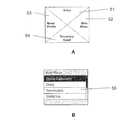
図1は、リモートコントローラ(RC)の形態のユーザ入力装置1を示し、このリモートコントローラは、ユニットの上部に配置されるLCDディスプレイ30と、ディスプレイの下方に配置されるボタンとを備えている。中心線に近接する配置が人間工学的に選択されている。リモートコントローラは、ロッカースイッチ10及び左側のACCEPTキー21、並びに右側ESCAPEキー22を備える。ロッカースイッチは、基本的なナビゲーションボタンであり、上下及び左右の方向をそれぞれ支持する4つのエリア11、12、13、14を有する4ウェイスイッチである。実際、ロッカースイッチの4つのエリアは、いずれかの所望の構成に配置される複数のキーに置き換えることができる。垂直軸は、例えば(i)メニューをスクロールアップ/ダウンし、(ii)数字を増やすか又は減らすように機能する。左右方向の水平軸は、例えば(i)時間をスクロールし、(ii)時間関連パラメータ又は2次パラメータを変更するために使用される。acceptボタンは基本的に「イエス」ボタンであり、(i)進む、入力する、選択する、了解する、又は確認する等の機能、及び(ii)ビューをズームインする機能を有する。Escapeボタンは基本的に「ノー」ボタンであり、(i)ノー、escape、前に戻る、exit、又は取り消しの機能、及び(ii)ビューをズームアウトする機能を有する。更に別の機能を上記機能に追加することができる。ディスプレイはドットマトリクスディスプレイであり、単色、グレイスケール、又はカラーのディスプレイとすることができる。ディスプレイは、普通RCの電源をオンにすると表示されるメインスクリーン(MS)を示している。MSはユーザに対し、RCによって制御されるシステムの状態を表示する。スクリーンは他の多くの使用状況においても使用される汎用的な構成を持つ(以下を参照)。具体的には、MSは中央の「分割スクリーン」エリアを含み、このエリアには、左側部分31及び右側部分32、並びに上側情報バー33及び下側情報バー34が含まれる。図示のビューでは、MSの上側バーに、現時点でRCと対になっているインスリンポンプ内のインスリンの残量、並びにRCのバッテリ状態が表示される。分割スクリーンには、現在の時刻及び日付が表示され、下側バーには対になるポンプの現在の基礎注入速度が表示される。RCの選択モードに応じて、分割スクリーンは、複数の入力スクリーンに使用される「デュアルモード」構成(以下参照)を有することができる。
システムの状態に応じて、他の情報、例えば進行中のボーラス送達及び/又は一時的基礎注入速度の状態を表示することができる。FIG. 1 shows a
Depending on the status of the system, other information can be displayed, such as the status of ongoing bolus delivery and / or temporary basal infusion rates.
RCには更に、内蔵式BG測定器用の上部ポート40が設けられ、このポートを通してBG試験片を挿入してBG値を求めることができる。RCの、例えば両側に更に一つ以上のキーを設けることができ、これによって使用頻度の少ない機能、例えばオンオフ及びキーボードロックを作動することができる。RCの電源は、取り替え可能又は再充電可能な電池から供給することができる。
リモートコントローラは、電源を入れると、初期設定(例えば、個人的な限界値及びアラーム設定値の入力)が済んでいるかどうかをチェックし、初期設定が済んでいる場合、上述のようにメインスクリーン又は「ステータススクリーン」に進む。いずれかのキーを押すと、ディスプレイには、図2Aに示すように、所定の位置に複数のアイテム51、52、53、54を有するショートカットメニュー(SM)スクリーンが表示される。以下に説明するように、このスクリーン内のテキストは、実際のボーラス条件又は基礎設定によって変わる。ロッカースイッチを使用して、ユーザは、4個の表示アイテム、即ちボーラス(bolus)スクリーン、プロファイル(profile)スクリーン、一時的基礎(temporaray basal)スクリーン、メニュー(menu)スクリーンの内のいずれかのスクリーンに直接進むことができる。メニュースクリーンを選択すると、メインメニューが表示され(図2B参照)、これによってユーザはスクロールして所望のメニューアイテム55、例えば日記(diary)、統計(statistics)、備忘録(reminders)、又は設定(setup)を選択することができる。従来のメニューを有するセクションを有することで、構造全体を壊すことなく機能の追加又は削除が容易に行える。更に、このようなメニュー構造によってカスタマイズ可能なインターフェースを提供することも容易になり、ヘルスケア専門家は、所定のユーザが利用できる機能の数をコントロールすることができる。このような図2Aに前述したショートカットメニューの種類は、メニューの一つ以上のサブレベルにも使用することができ、例えば図2Bの4個のメニューアイテムを図2Aに対応させて表示することができる。この場合、4個のサブレベルのショートカットメニューの内の一つ以上に、更なるレベルのショートカットメニューを設けることができる。The RC further has an
When the remote controller is turned on, the remote controller checks whether the initial settings (for example, input of personal limit values and alarm set values) have been completed, and if the initial settings have been completed, the main screen or Go to "Status Screen". When any key is pressed, a shortcut menu (SM) screen having a plurality of
上述から分かるように、4ウェイロッカースイッチ及びSMスクリーンは、ユーザ入力装置及びユーザ入力手段の具体的な実施形態を表わし、このユーザ入力装置では、ディスプレイは、ディスプレイ手段上の所定の位置に複数のメニューアイテムを同時に表示し、ユーザ入力手段によって、ユーザは、同時に表示されるメニューアイテムの各々を直接選択することができる。しかしながら、以下に詳細に説明するように、本ユーザインターフェースは、メニュー選択手段(例えば、ロッカーキー)を第2ユーザインターフェースと組み合わせることによりユーザ操作性を高めており、この場合、ディスプレイ手段は少なくとも一つのユーザ設定可能な薬剤送達パラメータを表示し、ユーザ入力手段は少なくとも一対のユーザ入力キーを含むキーボードを含み、各対によってユーザは、ユーザ制御可能な設定値が表示されているときに、ユーザ設定可能な薬剤送達パラメータを双方向に設定することができる。 As can be seen from the above, the 4-way rocker switch and the SM screen represent a specific embodiment of the user input device and user input means, in which the display has a plurality of positions at predetermined positions on the display means. Menu items are displayed at the same time, and the user input means allows the user to directly select each of the menu items displayed at the same time. However, as will be described in detail below, this user interface enhances user operability by combining menu selection means (for example, a rocker key) with the second user interface. In this case, the display means has at least one display means. Two user-configurable drug delivery parameters, wherein the user input means includes a keyboard including at least a pair of user input keys, with each pair allowing the user to set user settings when user-controllable setting values are displayed Possible drug delivery parameters can be set in both directions.
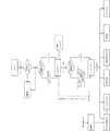
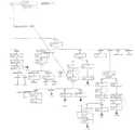
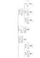
図3は、リモートコントローラー(RC)用の一般的なユーザインターフェース(UI)アーキテクチャの一実施形態を示している。UIはメインスクリーン(MS)を有し、メインスクリーンは普通、RCの電源を入れると表示される。MSは標準のMSとすることができるか、又は進行中のボーラス又は一時的基礎(TB)速度に関する追加的情報を表示することができる。RCの電源が初めてオンになると、ユーザは初期設定メニューに案内される。MSから、ユーザは、いずれかのキーを押すことにより、ショートカットメニュー(SM)に進むことができ、SMから特定のメイン機能を、直接又はメインメニュー(MM)を介して選択することができる。上述のように、進行中のボーラス又は一時的基礎(TB)速度がSMのオプションに影響する。
個々のメイン機能を参照すると、図4は、ユーザを「ボーラスを変更する」メニューに案内する3つの異なる方法を示している。即ち、(1)血糖値(BG)を、RC試験片ポートを使用して(又は、外部BG測定器によって)求めた後で案内する方法、(2)ユーザが直接案内する方法、又は(3)ボーラス計算機(メインメニュー(MM)介して選択)を使用することにより案内する方法を示している。更に、進行中のボーラスを中止することができる。FIG. 3 illustrates one embodiment of a general user interface (UI) architecture for a remote controller (RC). The UI has a main screen (MS), which is usually displayed when the RC is turned on. The MS can be a standard MS or can display additional information regarding the ongoing bolus or temporary basal (TB) speed. When the RC power is turned on for the first time, the user is guided to an initial setting menu. From the MS, the user can go to the shortcut menu (SM) by pressing any key and select a specific main function from the SM either directly or via the main menu (MM). As mentioned above, an ongoing bolus or temporary basal (TB) speed affects SM options.
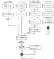
Referring to the individual main functions, FIG. 4 shows three different ways of guiding the user to the “Modify Bolus” menu. (1) A method for guiding blood glucose level (BG) after obtaining it using an RC test strip port (or by an external BG measuring device), (2) a method for direct guidance by a user, or (3 ) Shows how to guide by using a bolus calculator (selected via main menu (MM)). Furthermore, an ongoing bolus can be stopped.
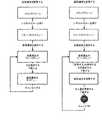
図5は、内蔵型BG測定器の使用方法、及び当該測定器を使用したボーラスメニューへの移行方法を示している。BG試験片が挿入されると、ユーザに対し、較正及びデータ入力の要求が行なわれるが、入力が行なわれないと、RCは直ちに「血液をリクエストする」に進む。十分な量の血液が試験片に付着し、設定正常範囲内のBGが計算されて表示される場合、ユーザに対し、ボーラス計算機に進む又はBGメニューから出るというオプションが提示される。ボーラスオプションが選択される場合、ユーザは、食事の炭水化物(含まれる場合)の量を入力するようリクエストされ、RCはボーラス送達の推奨量を計算して表示する。従って、ユーザは、所望のボーラス量を自由に設定するとき、この情報を手引きとして使用することができる。
図6は2つのTBオプションを示し、これによってユーザは、TBの設定又は取り消しを行うことができる。一時的基礎の設定方法については、図13を参照して後述する。FIG. 5 shows a method for using the built-in BG measuring device and a method for shifting to a bolus menu using the measuring device. Once the BG test strip is inserted, the user is prompted for calibration and data entry, but if no entry is made, the RC immediately proceeds to “Request Blood”. If a sufficient amount of blood adheres to the specimen and the BG within the set normal range is calculated and displayed, the user is presented with the option to proceed to the bolus calculator or exit the BG menu. If the bolus option is selected, the user is requested to enter the amount of carbohydrate (if included) in the meal and the RC calculates and displays the recommended amount of bolus delivery. Therefore, the user can use this information as a guide when freely setting a desired bolus amount.
FIG. 6 shows two TB options that allow the user to set or cancel the TB. A temporary basis setting method will be described later with reference to FIG.
図7A及び7Bは、ユーザが:(1)基礎速度(BR)プロファイルの閲覧、(2)BRプロファイルの変更、又は(3)BRプロファイルの再決定を行なう方法を示している。1日のBRプロファイルを繰り返すのではなく、開示されるシステムは、初期設定の間に初めて設定される7日間BRプロファイルを使用する。「BRプロファイルを変更する」機能を使用して、ユーザは、単一の日を選択し、当該日のBRプロファイルを変更することができる。別の構成として、ユーザは、7日間BRプロファイルの全てをリセットすることを決定できる。毎日のプロファイルが同じである場合、最初の(例えば月曜日の)BRプロファイルが入力された後、ユーザは当該プロファイルを後続の日にコピーすることができる。毎日のBRプロファイルを設定する方法について、図17及び18を参照しながら以下に説明する。
MMでは、ユーザは「ボーラス計算機(bolus calculator)」(上記参照)、「日記(diary)」(フローチャートでは「ログブック」とも表記)、「備忘録(reminders)」、「統計(statistics)」及び「設定(setup)」の中から選択を行なうことができる。7A and 7B show how a user can: (1) view a basal velocity (BR) profile, (2) change a BR profile, or (3) redetermine a BR profile. Rather than repeating a one-day BR profile, the disclosed system uses a seven-day BR profile that is set for the first time during initial setup. Using the “Change BR Profile” function, the user can select a single day and change the BR profile for that day. Alternatively, the user can decide to reset all of the BR profiles for 7 days. If the daily profile is the same, after the first (eg, Monday) BR profile is entered, the user can copy the profile on subsequent days. A method for setting a daily BR profile will be described below with reference to FIGS.
In MM, a user can use “bolus calculator” (see above), “diary” (also referred to as “logbook” in the flowchart), “reminders”, “statistics” and “statistics”. A selection can be made from “setup”.
図8は、ユーザが日記機能を実行するために利用することができるオプションを示している。「ビュー」オプションでは、ディスプレイ上に7日間ビューが開き、事前に選択された種類の情報、例えばBG値、又は複数の種類の情報の組み合わせ、例えばBG値とボーラスが表示される。所定の種類の情報について、各イベントが特定のアイコンによって表示される。この時点でユーザは2つのオプションを持ち、別の種類の情報を選択して表示するか、又はデイビューを選択してほぼ同じ情報を1日の24時間に亘って細く表示する。デイビューの状態のとき、ユーザは異なる種類の情報を選択することもできる。デイビューの状態で、ユーザは、閲覧により表示されたアイコンのいずれかを選択し、次に関連する詳細情報をリクエストして「アクションカード」ビューに表示させることができる。アクションカードが表示されると、ユーザは、選択日、並びに選択日の前日又は翌日の両方について、選択された種類の情報に関する前のカード又は次のカードを閲覧することができる。所定のアクションカードが選択されると、ユーザは(許可される場合)、表示される情報について異なるオプション、即ち、変更、消去、又は非表示を選択することができる。「追加する」オプションでは、ユーザは、日にちと情報の種類を選択する。次に、ユーザに対して「アクションカードを変更する」ビューが表示され、よってユーザは、選択された種類の情報、例えば食事量及び時刻について関連する種類の情報を入力することができる。
図9は、ユーザが備忘録機能を実行するために利用することができるオプションを示している。備忘録機能は、日記機能とほぼ同じように実行される。即ち、ユーザに対して、ウィークビュー、デイビュー、及び「備忘録カード」(アクションカードの替わりに)オプション、並びに備忘録の種類が提示される。従って、ユーザは、アクションカード情報に関して上述したように備忘録の編集及び追加を行うことができる。更に、新規の備忘録を設定する場合、ユーザは繰り返しオプションを持ち、即ち日単位又は週単位の繰り返しを選択することができる。FIG. 8 shows options that can be used by the user to perform the diary function. In the “view” option, the view opens on the display for 7 days and displays pre-selected types of information, eg, BG values, or a combination of multiple types of information, eg, BG values and boluses. For a given type of information, each event is displayed with a specific icon. At this point, the user has two options to select and display another type of information, or select a day view to display nearly the same information for 24 hours a day. When in the day view state, the user can select different types of information. In the day view state, the user can select any of the icons displayed by browsing and then request the relevant details to be displayed in the “Action Card” view. When the action card is displayed, the user can view the previous or next card for the selected type of information for both the selected date and the previous or next day of the selected date. Once a given action card has been selected, the user (if allowed) can select different options for the displayed information: change, delete, or hide. In the “add” option, the user selects the date and type of information. Next, the “change action card” view is displayed to the user, so that the user can enter the type of information selected, for example, the type of information related to the amount of meal and time.
FIG. 9 shows the options that the user can use to perform the memorandum function. The memorandum function is executed in almost the same way as the diary function. That is, a week view, a day view, a “memorandum card” (instead of an action card) option, and a memorandum type are presented to the user. Accordingly, the user can edit and add the memorandum as described above with respect to the action card information. Furthermore, when setting up a new memorandum, the user has a repeat option, i.e., can select daily or weekly repeats.
図10は、ユーザが統計機能を実行するために利用することができるオプションを示している。統計機能では、一つ以上の平均値、例えば14日間又は30日間の平均値を、選択された種類の情報、例えば毎日の基礎又は毎日のボーラスに関して表示できる。
図11は、ユーザが時刻及び日付、地理的設定、並びにアラーム等の設定機能を実行するために利用することができる種々のオプションを示している。FIG. 10 illustrates options that can be utilized by a user to perform a statistical function. In the statistical function, one or more average values, for example 14 or 30 day average values, can be displayed for selected types of information, for example daily basis or daily bolus.
FIG. 11 illustrates various options that can be utilized by the user to perform setting functions such as time and date, geographic settings, and alarms.
図29に示すように、ポンプはRCを介して制御され、これにより新規設定をポンプに送信することができるが、通信は双方向で行なわれ、よってポンプもアラーム等の情報をRCに送信することができる。特に後者の場合、通信を2つのユニット間で維持することが重要である。図23に示すように、通信が第1の所定時間、例えば10分を超える長さに亘って不能になると、最初の「接続障害」警告がメインスクリーンに現われる。通信が第2の所定時間、例えば2時間以内に再接続されない場合、2回目の「接続障害」警告がメインスクリーンに現われ、聴覚及び/又は触覚アラームが鳴動する。
後述では、入力オプションの内の幾つかについて説明し、上述のユーザ入力装置に関する複数の異なるユーザ指向性の形態を示す。As shown in FIG. 29, the pump is controlled via RC, which allows new settings to be sent to the pump, but communication is bi-directional, so the pump also sends alarms and other information to the RC. be able to. Especially in the latter case, it is important to maintain communication between the two units. As shown in FIG. 23, when communication is disabled for a first predetermined time, eg, more than 10 minutes, an initial “connection failure” warning appears on the main screen. If the communication is not reconnected within a second predetermined time, eg, 2 hours, a second “connection failure” warning will appear on the main screen and an audible and / or tactile alarm will sound.
In the following, some of the input options will be described and a number of different user-directed forms for the user input device described above will be shown.
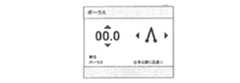
ユーザが注入するボーラスを直接、即ちボーラス計算機を使用することなく入力しようとする場合、UPキーを使用してSMのボーラスメニューポイントが選択され、ユーザは「デュアルモード」構成である設定ボーラス入力スクリーンに誘導される(例えば図13を参照)。デュアルモードスクリーンには、ユーザによる制御が可能な2つの設定、例えば2つのパラメータが表示され、これらのパラメータは同時に(即ち、同じスクリーンを使用して)、リモートコントローラに設けられるキーボードを使用してユーザが直接設定することができる。本実施形態では、4ウェイロッカースイッチを設けて、2つの設定を「上下」するか、又はスクロールして制御することができる。図示のように、スクリーンの画像には、2組の矢印36、37、38、39が設けられて、4ウェイスイッチを操作するときにユーザを支援する。2つの異なる設定が、制御可能であると同時に表示可能であるので、使用が容易且つ確実なユーザインターフェースが得られる。ディスプレイはまた、更に別の情報を提供する上部バー及び下部バーを含んでいる。
具体的には、図12のボーラス入力スクリーンの左側には、インスリン単位等の選択された量を示す数値(最初は0.0を示す)を、上下一組の矢印と共に示す。右側には、選択された種類のボーラス注入、例えば「direct」(例えば、出来る限り迅速に)、「extended」(延長して)又は「sawtooth」(ギザギザに増減させる)(デュアルフェーズとも呼ばれる)を示す記号を、左右一組の矢印と共に示す。後述のように、ボーラスを設定する場合、ユーザは上下キーを使用して薬剤量を入力し、「種類メニュー」をスクロールすることにより注入種類を選択する。所望のボーラスを行なうために、ACCEPTを押すと、チェックマークがスクリーンに現われる。このチェックマークは、ポンプユニットが、命令が受信されており、且つ実行される予定であることを確認していることを示し、その後リモートコントローラは自動的にステータススクリーンに戻る。当該スクリーンにはこのとき、ボーラスの送達中であれば、ボーラス(残りの時間及びインスリン量)が表示されている。ボーラス計算機を介して「ボーラスを変更する」スクリーンに入っている場合、下部のバーにボーラスに関する示唆を表示することができる。If the user wants to enter the bolus to be injected directly, i.e. without using a bolus calculator, the SM bolus menu point is selected using the UP key, and the user sets the bolus input screen in a "dual mode" configuration. (See, for example, FIG. 13). The dual mode screen displays two settings that can be controlled by the user, eg, two parameters, which are simultaneously (ie, using the same screen) using the keyboard provided on the remote controller. It can be set directly by the user. In this embodiment, a four-way rocker switch is provided, and the two settings can be "up and down" or scrolled to control. As shown, the screen image is provided with two sets of
Specifically, on the left side of the bolus input screen of FIG. 12, a numerical value (initially 0.0) indicating a selected amount such as an insulin unit is shown together with a pair of up and down arrows. On the right side is the selected type of bolus injection, eg “direct” (eg as quickly as possible), “extended” (extended) or “sawtooth” (increase or decrease) (also called dual phase) The symbols shown are shown with a pair of left and right arrows. As will be described later, when setting a bolus, the user uses the up and down keys to input a drug amount, and selects an injection type by scrolling the “type menu”. Press ACCEPT to perform the desired bolus and a check mark appears on the screen. This check mark indicates that the pump unit has confirmed that the command has been received and will be executed, after which the remote controller automatically returns to the status screen. At this time, if the bolus is being delivered, the bolus (remaining time and insulin amount) is displayed on the screen. If you are in the “Modify Bolus” screen via the bolus calculator, you can display bolus suggestions in the bottom bar.
ユーザが送達中のボーラス注入をキャンセルする場合、SMスクリーンが選択され、このスクリーンには「ボーラス」の代わりに「ボーラスを中止する」が表示される。ユーザは「ボーラスを中止する」というメニューアイテムを選択し、ACCEPTを押して中止を確認する。
図13は、TB速度がプログラムされるデュアルモードスクリーンの別の使用方法を示している。具体的には、TB入力スクリーンの左側には、送達中の基礎速度又はプロファイルについて選択されたパーセント調整値を、一組の上下の矢印と共に示す数値のパーセント表示(最初は0%を表示)が表示される。右側には、時間及び分で表示されるTBの選択された期間が、一組の左右の矢印と共に示される。後述するように、TBの速度を設定する場合、ユーザは、例えば(−100%)〜(+100%)から選択することができるパーセント調整値、並びにTB速度の所望の期間を入力する。所望のTB速度を伝達するために、ACCEPTを押すと、チェックマークがスクリーンに現われる。このチェックマークは、ポンプユニットが、命令が受信されており且つ実行される予定であることを確認していることを示し、その後リモートコントローラは自動的にステータススクリーンに戻る。当該スクリーンにはこのとき、TB速度の伝達中であれば、TB速度が分割スクリーンビュー(パーセントの変化及び残り時間)に表示されている。図14は、ボーラス及びTB速度の両方が伝達中であることを示すステータススクリーンを示している。If the user cancels a bolus injection during delivery, the SM screen is selected and this screen displays “Stop Bolus” instead of “Bolus”. The user selects the menu item “Stop Bolus” and presses ACCEPT to confirm the cancellation.
FIG. 13 shows another use of the dual mode screen where the TB speed is programmed. Specifically, on the left side of the TB input screen is a numerical percentage display (initially showing 0%) showing the percentage adjustment value selected for the basal rate or profile being delivered, along with a set of up and down arrows. Is displayed. On the right side, the selected period of TB displayed in hours and minutes is shown with a set of left and right arrows. As will be described later, when setting the TB speed, the user inputs, for example, a percent adjustment value that can be selected from (−100%) to (+ 100%), and a desired period of the TB speed. When ACCEPT is pressed to convey the desired TB rate, a check mark appears on the screen. This check mark indicates that the pump unit has confirmed that the command has been received and will be executed, after which the remote controller automatically returns to the status screen. At this time, if the TB speed is being transmitted, the TB speed is displayed in the split screen view (percent change and remaining time). FIG. 14 shows a status screen indicating that both bolus and TB speed are being transmitted.
新規のBRプロファイルのプログラミングを一実施例として使用し、図15〜18に別の種類のデュアルモードスクリーンを示す。初期設定において、又はBRプロファイルを再決定することが望ましい場合、ユーザは「プロファイルを決定する(define profile)」スクリーンに誘導される。
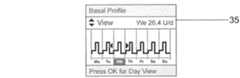
具体的には、SMの「基礎プロファイル(basal profile)」を起動する場合、ユーザはBRプロファイルの「ウィークビュー」スクリーンに誘導される(図15参照)。このスクリーンは2組の矢印を含み、第一組の矢印は上部情報バーの下方に配置される「スピナーバー」35の中で使用され、第2組の矢印は所定の選択日のために使用される。RC上の該当する上下キーを使用して、ユーザはスピナーバーのオプション、例えば「view(ビュー)」、「edit(変更)」、又は「redefine(再決定)」の間で切り替えを行なうことができる。それに対応して、左右キーを使用して、ユーザは所定の日を選択することができる。「redefine(再決定)」が選択されると(図16参照)、図示の実施形態に示すように第2組の矢印が消え、BRプロファイルのみを週全体について再決定することができる。従って、ACCEPTを押すと、ユーザはBRプロファイル再決定スクリーンに誘導される(図17参照)。Using a new BR profile programming as an example, FIGS. 15-18 illustrate another type of dual mode screen. At initialization or if it is desired to redetermine the BR profile, the user is directed to a “define profile” screen.
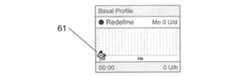
Specifically, when activating the SM “basal profile”, the user is directed to the “weak view” screen of the BR profile (see FIG. 15). This screen contains two sets of arrows, the first set of arrows being used in a “spinner bar” 35 located below the upper information bar, the second set of arrows being used for a given selection date Is done. Using the appropriate up / down keys on the RC, the user can switch between spinner bar options, eg, “view”, “edit”, or “redefine”. it can. Correspondingly, using the left and right keys, the user can select a predetermined day. When “redefine” is selected (see FIG. 16), the second set of arrows disappears as shown in the illustrated embodiment, and only the BR profile can be redetermined for the entire week. Thus, pressing ACCEPT takes the user to the BR profile redetermination screen (see FIG. 17).
本発明の一態様によれば、BRプロファイルス変更クリーンは、注入速度を時間の関数として表示する注入プロファイルをグラフ形式で表示する。プロファイルには、それぞれが1つの期間とそれに関連する注入速度(BR)を示す複数の連続セグメントが含まれる。図示の実施形態では、24個のセグメントが24時間の期間に使用され、プロファイルが実線として示されている。スクリーンには更に、所定の時点の所定の注入速度に対応する位置に配置されるインジケータ61(中心にドットを有する円)を表示する。所定の時点及び所定の注入速度の初期設定はいずれも0である。インジケータは2組の矢印に関連付けられ、これらの矢印は、所望のBRに応じて上下に、及び所望のセグメント、即ち所望の時点に応じて前後に、インジケータを移動させることができることを示している。このように、ロッカースイッチを使用して、RCには、ユーザがインジケータを所望の時点に応じて移動させることを可能にする第1ユーザ入力手段と、ユーザがインジケータを所望の注入速度に応じて移動させることを可能にする第2ユーザ入力手段が設けられ、従ってユーザは、所望の期間に対応させてスクリーン上でインジケータを移動させることにより、所望の期間に亘る連続プロファイル62をグラフ形式で描くことができ、描かれたプロファイルはBRプロファイルをグラフ形式で示す。インジケータに対応する実際の時刻及びBRは、下部バーに表示される。プロファイルが完成すると、ユーザはACCEPTを押すが、プロファイルが完成しない場合、例えば「欠落」しているプロファイル部分が明滅することにより、これが通知される(図18参照)。
開示されるRCの実施形態では、BRプロファイルは7日間プロファイルとして定義される。最初の日(例えば、月曜日)のプロファイルをプログラムする場合、プロファイルを了解すると、ユーザは「事前に設定された」同じプロファイルを表示する次の日のスクリーンに誘導され、これを了解する(且つ1週間が終わるまで繰り返す)ことができる。これは、プロファイルが、複数の日、又は週7日間全てに亘って同じである場合が多いので都合が良い。次の日にプロファイルをコピーすることが望ましくない場合、ユーザは単に新規プロファイルの再描画を開始するか、又は前日のプロファイルを変更する。According to one aspect of the present invention, the BR profile change screen displays an injection profile in graphical form that displays the injection rate as a function of time. The profile includes a plurality of consecutive segments, each indicating one period and the associated infusion rate (BR). In the illustrated embodiment, 24 segments are used in a 24 hour period and the profile is shown as a solid line. Further, an indicator 61 (a circle having a dot at the center) arranged at a position corresponding to a predetermined injection speed at a predetermined time is displayed on the screen. The initial settings for the predetermined time point and the predetermined injection rate are both zero. The indicator is associated with two sets of arrows, which indicate that the indicator can be moved up and down depending on the desired BR and back and forth depending on the desired segment, i.e. the desired point in time. . Thus, using the rocker switch, the RC allows the user to move the indicator according to the desired point in time, and the first user input means that allows the user to move the indicator according to the desired injection rate. A second user input means is provided that allows the user to move, so that the user draws a
In the disclosed RC embodiment, the BR profile is defined as a 7 day profile. When programming a profile for the first day (e.g., Monday), accepting the profile directs the user to the next day's screen displaying the same "pre-set" profile and accepts this (and 1 Repeat until the end of the week). This is advantageous because the profile is often the same over multiple days, or all seven days a week. If it is not desirable to copy the profile the next day, the user simply starts redrawing the new profile or changes the previous day's profile.
次に、図19〜23を参照して日記機能の態様について説明する。この機能によってデュアルモードスクリーンの更なる実施例が提供される。
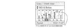
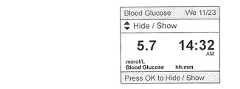
具体的には、MMを使用してユーザは日記機能を選択する。この日記機能は、「diary−options(日記オプション)」のビュー/追加メニューを介して、ユーザを「diary−week view(日記−ウィークビュー)」スクリーンに誘導する(図19参照)。このスクリーンは、図15を参照して説明した基礎プロファイルの上述のウィークビューと同様であり、つまりスピナーバー、及び日にちが選択可能なウィークビューを含み、これら両方は、4ウェイロッカーキーによって提供される2組のキーを使用して選択可能である。上下キーを使用して、ユーザは、次の日記アイテムオプション、即ち血糖(BG)、BG及びボーラス(図20参照)、BG及び基礎(つまりBRプロファイル)、及びその他から選択を行なって表示させることができる。日記アイテムオプションは、単一種類のデータ、例えばBG、又は一つ以上のデータ種類の組み合わせ、例えばBGと基礎を表わすことができる。更に、その他の項目に、複数のデータ種類、例えば食事、薬剤治療、又は運動を含めることができる。左右キー及びその後にACCEPTキーを使用して、ユーザはデイビュー(day view)を選択することができる(図21参照)。ウィークビュー及びデイビューの両方において、個々のデータユニットは、記号63によって表わされ、例えばBGに関しては液滴又は血液のマーク、或いは基礎に関しては表示プロファイルの変化によって表わされる。デイビューにおいて、第2組の矢印を使用して単一の記号を表示する場合、左右キーによってユーザは、直前の又は次の記号に前後にスクロールすることができ、これは「隣接する」日の記号を含む。選択した所定の記号にACCEPTキーを使用して、ユーザは、選択された記号に関連するデータを表示する「diary action card(日記アクションカード)」スクリーンに誘導される(図22参照)。所定の記号及び当該記号に関連するデータは、次のデータグループの内の一つに含まれるデータを含むことができるデータユニットと考えることができる。即ち、(i)血糖値を表わす記号、一時点を表わす時間データ、及び血糖値、(ii)食事を表わす記号、一時点を表わす時間データ、及び食事の特徴を表わす値、(iii)ボーラス送達を表わす記号、一時点を表わす時間データ、及びボーラスの量、(iv)運動を表わす記号、一時点を表わす時間データ、及び運動のレベルを表わす値、及び(v)基礎送達速度の変化量、薬剤の摂取、又は病状を表わす記号、及び一時点を表わす時間データ、である。実際、他の種類のデータを保存することが望ましい場合がある。また、「diary action card(日記アクションカード)」スクリーンにはスピナーバーが含まれ、スピナーバーによってユーザが「edit(変更)」、「delete(消去)」、及び「hide/show(非表示/表示)」を切り替えることができると望ましい。データの種類に応じて、これらのアクションの内の一つ以上を許可することができ、例えば一部の種類のデータは消去又は変更できない。Next, an aspect of the diary function will be described with reference to FIGS. This feature provides a further embodiment of a dual mode screen.
Specifically, the user selects the diary function using MM. This diary function guides the user to a “diary-week view” screen via a view / addition menu of “diary-options” (see FIG. 19). This screen is similar to the above week view of the basic profile described with reference to FIG. 15, ie it includes a spinner bar and a week view with a selectable date, both of which are provided by a 4-way rocker key. These can be selected using two sets of keys. Using the up and down keys, the user can select and display from the following diary item options: blood glucose (BG), BG and bolus (see FIG. 20), BG and basis (ie BR profile), and others. Can do. The diary item option can represent a single type of data, eg BG, or a combination of one or more data types, eg BG and basis. In addition, other items may include multiple data types, such as diet, medication, or exercise. Using the left and right keys followed by the ACCEPT key, the user can select a day view (see FIG. 21). In both week view and day view, individual data units are represented by
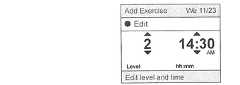
ユーザが「diary−options(日記オプション)」メニューの「add(追加)」を選択する場合、ユーザは、例えばスピナーバー及び日にち選択機能を含む、ビューオプションのスクリーンと同様のウィークビュースクリーンに誘導される。しかしながら、日にち及びデータの種類がスピナーバーから選択されると、ACCEPTキーを押すことにより、ユーザは入力される選択されたデータの種類に対応するアクションカード編集スクリーンに直接誘導される(図23参照)。この図は、追加される運動アイテムのレベル及び時間の入力方法を示している。
上述では、薬剤送達装置のユーザインターフェースの態様について説明した。従って、以下の記述では、説明した種々の態様又は機能の内の一つ以上を取り入れたユーザインターフェースと組み合わせて使用するのに適した薬剤送達システムを例証する。本発明について、図24〜29に開示されるポンプユニット及びリモートコントローラユニットを参照しながら説明するが、本開示内容は、ポンプユニットと、コントローラユニット又は他の外部ユニット、例えばPC又はPDAとの組み合わせを備えるあらゆる形態のシステムに広く適用可能である。例えば、本発明の種々の態様は、複数の製造業者が現在市販している種類のプログラム可能な携帯型インスリン注入ポンプに使用することができる。それら製造業者として、限定しないが、例えばPARADIGMという登録商標を持つMedtronic MiniMed、OmniPodという登録商標を持つInsulet Corporation、Deltec COZMOという登録商標を持つSmiths Medical、及びその他の会社を挙げることができ、これらのポンプにはリモートコントローラが設けられるか、又はこれらのポンプはリモートコントローラと一緒に使用することができることができる。If the user selects “add” in the “diary-options” menu, the user is directed to a week view screen similar to the view options screen, including, for example, a spinner bar and a date selection function. The However, once the date and data type are selected from the spinner bar, pressing the ACCEPT key will direct the user directly to the action card editing screen corresponding to the selected data type to be entered (see FIG. 23). ). This figure shows a method for inputting the level and time of the exercise item to be added.
In the above, the aspect of the user interface of the medicine delivery device has been described. Accordingly, the following description illustrates a drug delivery system suitable for use in combination with a user interface that incorporates one or more of the various aspects or functions described. The present invention will be described with reference to the pump unit and remote controller unit disclosed in FIGS. 24-29, but the present disclosure is a combination of a pump unit and a controller unit or other external unit such as a PC or PDA. It can be widely applied to all forms of systems comprising For example, various aspects of the present invention can be used with programmable portable insulin infusion pumps of the type currently marketed by multiple manufacturers. These manufacturers include, but are not limited to, for example, Medtronic MiniMed with the registered trademark PARADIGM, Insul Corporation with the registered trademark OmniPod, Smiths Medical with the registered trademark Deltec COZMO, and other companies. The pumps can be provided with a remote controller or these pumps can be used with a remote controller.
図24は、パッチ(又はカニューレ)ユニット400の形態の皮膚接触型装置を示している。パッチユニットは、下側接着面431を有する可撓性シート部材430の上に配置される比較的剛性のボディ部分414を含み、下側接着面431には接着剤が塗布され、これによってシートを被験者の皮膚に接着させることができる。シート部材は中心開口432を含み、この開口を通してカニューレを挿入することができる。ボディ部分はハウジング部分412を含み、このハウジング部分にはカニューレ挿入機構が配置される(後述)。ボディ部分は更に、ハウジングから伸びる2つのスライド脚部材413を含み、これらの脚はパッチユニットに剛性を付与し、更にはポンプ/容器ユニットがパッチユニットに取り付けられるときのガイド手段として機能する(後述)。ハウジングには一組の対向溝420が設けられ、これらの対向溝は、パッケージング用の、続いてポンプユニット用の取り付け手段として機能する。ハウジングは更に、取り付けられるポンプユニット450の対応する流体流出口と流体を連通するように取り付けられる流体流入口415と、取り付けられるポンプユニットの電気コンタクトを作動させるアクチュエータ416と、ポンプユニットが初めて取り付けられるときにカニューレ挿入機構を解放し、よってカニューレが開口432に挿入される解放部材417とを備える。ハウジング部分412は更に、ポンプユニット上の対応する結合構造と係合するキャッチ419を含む。図示のように、カニューレ951が挿入されると(図25参照)、カニューレはポンプユニットによって保護されるが、ポンプユニットは、図26に示すように、挿入部位を検査するために取り外すことができる。
図26は、パッチユニット1010とポンプユニット1050が並ぶ別の実施形態を示し、図27は、ポンプユニットが完全にではあるが解放可能に取り付けられた状態を示している。具体的には、図26は、医療装置1000の一実施形態を示し、医療装置1000は、図24に示す種類のカニューレユニット1010と、カニューレユニット1010に装着可能なポンプ(又は、容器)ユニット1050とを含む。図示の実施形態では、カニューレユニットはシャフト付きのハウジング1015を含み、シャフトには、ポンプユニットの一部分1051が挿入される。シャフトは開口1012を有する蓋部分1011を有し、蓋の自由端は下側突起(図示せず)を有する可撓性ラッチ部材1013を形成しており、下側突起がポンプユニットの対応する凹部1052と嵌合することにより、ポンプユニットがカニューレユニットのシャフトに挿入されるとスナップ嵌合が行なわれる。通気開口1054も観察することができる。ハウジング1015には一対の対向脚1018が設けられ、ハウジングは皮膚接触面として機能する下側接着面1020を有する可撓性シート部材1019の上部に取り付けられる。シート部材はカニューレ1017用の開口1016を含む。FIG. 24 shows a skin contact device in the form of a patch (or cannula)
FIG. 26 shows another embodiment in which the
図示のように、カニューレユニットのハウジングからは、カニューレが斜めの角度で伸び、カニューレは、皮膚表面を貫通するカニューレ挿入部位を、例えば挿入直後に検査することができるように配置される(図では、カニューレ全体を見ることができる)。図示の実施形態では、蓋の開口により挿入部位の検査が容易である。ポンプユニットは、カニューレユニットに接続されると、カニューレ及び挿入部位を完全に覆い、且つ水、埃、及び機械力等の外部の影響から保護する(図27参照)が、ポンプユニットは取り外し可能にカニューレユニットに接続されており、ポンプユニットをカニューレユニットから解放し(ラッチ部材を持ち上げることにより)、完全に又は部分的に引き出すことができるので、挿入部位をいつでも所望の時点で検査することができる。このような構成により、経皮装置、例えば図示のソフトカニューレを有する薬剤送達装置が提供され、ソフトカニューレは通常の使用の間は良好に保護されるが、ポンプユニットを完全に又は部分的に取り外すことにより、必要に応じて検査することができる。実際、挿入部位を少なくとも或る程度、ポンプユニットを装着している間に、例えば対応する開口又は透明領域により検査できるように所定の装置を製作することができる。しかしながら、装着するポンプユニットは、ポンプユニットを装着している間に検査を行うために挿入部位が完全に又は部分的に遮られるとしても、使用中に挿入部位を堅牢に保護する。図示の実施形態では斜めになったカニューレを使用しているが、別の実施形態では、皮膚接触面に対して垂直に、針又はカニューレを挿入することができる。
図28は、図26に示すユニットと同じ種類のポンプユニット300の分解図である。ポンプユニットは上側ハウジング部分310、及び下側ハウジング部分320を含み、これらの部分を組立てると、容器ユニットの他の構成部品、即ちポンプアセンブリ330、アクチュエータ340、容器350、及び電子制御手段360のための防水性筐体を形成する。ユーザに提供される初期状態では、保護キャップアセンブリ370がユニットに取り付けられる。As shown, from the housing of the cannula unit, the cannula extends at an oblique angle and the cannula is positioned so that the cannula insertion site that penetrates the skin surface can be examined, for example immediately after insertion (in the figure). Can see the whole cannula). In the illustrated embodiment, the insertion site is easily inspected by the opening of the lid. When connected to the cannula unit, the pump unit completely covers the cannula and insertion site and protects against external influences such as water, dust and mechanical forces (see FIG. 27), but the pump unit is removable. Connected to the cannula unit, the pump unit can be released from the cannula unit (by lifting the latch member) and fully or partially withdrawn so that the insertion site can be inspected at any desired time . Such a configuration provides a transdermal device, such as a drug delivery device having a soft cannula as shown, which is well protected during normal use, but completely or partially removes the pump unit. Therefore, it can be inspected as necessary. In fact, certain devices can be made so that the insertion site can be inspected at least to some extent, for example by means of corresponding openings or transparent areas, while the pump unit is mounted. However, the installed pump unit provides a robust protection during use, even if the insertion site is completely or partially blocked for testing while the pump unit is installed. While the illustrated embodiment uses an angled cannula, in another embodiment, a needle or cannula can be inserted perpendicular to the skin contacting surface.
FIG. 28 is an exploded view of a
下側ハウジング部分は、ユーザが容器(後述)を外側から検査することを可能にする透明材料により形成され、撥水加工水抜き穴322が配置される開口321を有する。窓開口326付きのシート部材325は下側ハウジング部分の下側表面に取り付けられ、これにより、容器上の窓を除く透明部分が遮蔽される。シート部材を使用して、薬剤の種類及び量といったユーザ情報を表示することができる。
ポンプアセンブリ330は、流体制御用流入口バルブ及び流出口バルブを有するピストン式ポンプ膜を含む膜ポンプの形態である。ポンプは、複数のボディ部材を含む一般的な層構造を有し、これらのボディ部材の間に可撓性メンブレン層が配置されることにより、ポンプチャンバ、流入口バルブ及び流出口バルブ、並びに一つ以上の安全バルブを形成することができる。これらの層はクランプ338によって一括して保持される。ポンプは更に、ポンプ内にスライド可能に収容される(分かり易く示すためにポンプの外側に示す)中空接続針の形態の流体コネクタ335を含み、これによって、保護キャップアセンブリ370が作動すると、ポンプが容器に接続される。このような膜ポンプに関する更に詳細な説明は、本出願人による同時係属中のPCT/EP2006/060277を参照されたく、この特許文献を参照により本明細書に組み込む。The lower housing portion is formed of a transparent material that allows a user to inspect a container (described below) from the outside, and has an
The
ポンプアクチュエータは、クランプによってポンプアセンブリが取り付けられるコイルアクチュエータの形態である。このようなコイルアクチュエータに関する更に詳細な説明は、図1〜9に関連する上記説明、及び本出願人による同時係属中の国際公開番号WO2005/094919を参照されたく、この特許文献を参照により本明細書に組み込む。
薬剤容器は、針貫通可能な隔壁354を含む事前充填式の可撓性折り畳み式ポーチ350の形態であり、この隔壁によって流体コネクタを容器の内部に漏れを生じることなく押し込むことができるので、ポンプとの間に流体を連通させることができる。クリップホルダ352が容器に取り付けられ、これによって、容器自体に影響を与えることなくハウジングに容器を取り付けることができる。容器の下には(ユニットの下側表面から観察されるように)シート(図示せず)が配置され、シートがコントラスト強調パターン、例えば白地に描かれた黒線を含むことにより、薬剤に含まれる不純物、例えばインスリン中の繊維形成を容易に目視確認できる。The pump actuator is in the form of a coil actuator to which the pump assembly is attached by a clamp. For a more detailed description of such a coil actuator, see the above description in relation to FIGS. 1-9 and co-pending International Publication No. WO 2005/094919 by the Applicant, hereby incorporated by reference. Include in the book.
The drug container is in the form of a pre-filled flexible
電子制御手段360は、プロセッサ361を搭載したPCB又はフレキシブルプリント基板362を含み、このプロセッサは、ポンプアセンブリ、バッテリ366、アラームを出す音響トランスデューサ365、及びユーザとの通信インターフェース、並びにアクチュエータに取り付けられるコンタクトを制御し、このアクチュエータによって、初回使用時に、ユーザが制御手段を起動することができる(アクチュエータ216を介して)。制御手段は、容器とリモートコントローラとの無線通信を可能にする受信機及び/又は送信機を含むことができる。
保護キャップアセンブリ370は、初期状態において容器ユニットに固定される取り付け部材371と、取り付け部材にスライドして取り付けられる作動「プッシュボタン」部材372とを含む。容器ユニットをそのプライマリパッケージ(図示せず)から取り外すとき、ユーザは作動部材を容器ユニットに向かって押し込む。このように作動させることにより、3つのアクションが行なわれる。即ち、作動部材上の第1の突起は容器ユニット上のコンタクトを作動させ、よって電子機器が作動し、第2の突起はポンプアセンブリと係合し、ポンプアセンブリから容器に流体コネクタ335を押し出し、これによって容器とポンプの間に流体が連通する。第3に、作動部材を押し込むことにより取り付け部材が「アンロック」され、当該部材、よって作動部材を容器ユニットから取り外すことができる。その後、容器ユニットはパッチユニットに接続することができる。The electronic control means 360 includes a PCB or flexible printed
The
図29は、プロセスユニット200(ここでは、図26のポンプユニット1050に対応)、及びコントローラユニット100(ここでは、ポンプユニット用の無線「リモートコントローラ」又は「外部通信装置」の形態)の模式図である。このようなユニットの一般的な構造は当業者には公知であると考えられるが、本発明の所望の機能を提供するために必要な回路の詳細な説明は、参照により本明細書に組み込まれる米国特許出願公開第2003/0065308号を参照されたい。
具体的には、図29は、ポンプユニット200及びリモートコントローラ100に含まれる種々の機能部品又はモジュール(即ち、単一部品群又は部品グループ群)の簡易ブロック図である。リモートコントローラユニットは、ハウジング101、CPUを含むリモートプロセッサ110、制御プログラム及び操作データとクロックを格納するメモリ要素、ユーザによる情報の操作を可能にするLCDディスプレイ120、ユーザからの入力を取り込むキーパッド130、ユーザに情報を提供する音声アラーム140、ユーザに情報を提供するバイブレータ150、コントローラに電源を供給するメインバッテリ160、コントローラのメモリ保持を行なうバックアップバッテリ161、ポンプユニットに信号を送信する無線周波数(RF)テレメトリ送信機170、ポンプユニットから信号を受信する無線周波数(RF)テレメトリ受信機180、並びに第2送信機190を備える。コントローラは更に、赤外線(IR)ポート又はRF入力/出力システムのようなポート185、或いは血糖測定器(BGM)、血糖連続測定装置(CGM)、PC、又はPDAのような別の装置と通信するUSBポートを含む。FIG. 29 is a schematic diagram of the process unit 200 (here, corresponding to the
Specifically, FIG. 29 is a simplified block diagram of various functional components or modules (that is, a single component group or component group group) included in the pump unit 200 and the
また図29に示すように、ポンプユニット200は、ハウジング201、CPU及び制御プログラムと操作データを格納するメモリ要素を含むローカルプロセッサ電子機器210、システムに電源を供給するバッテリ260、リモートユニットに通信信号を送信するプロセスユニットRFテレメトリ送信機270、リモートユニットから信号を受信するプロセスユニット無線周波数(RF)テレメトリ受信機280、第2プロセスユニット受信機240(ユーザにフィードバックを供給する音声アラームに使用される音響トランスデューサのコイルの形態とすることができる)、薬剤を格納する容器230、並びに、容器から経皮装置を介して患者の体内に薬剤を放出するポンプアセンブリ220を含む。別の実施形態では、ポンプユニットは更に、ユーザに情報を提供するLCDディスプレイ、ユーザからの入力を取り込むキーパッド、並びにユーザに情報を提供するバイブレータ又は他の触覚アクチュエータを含むことができる。RF送信は、Bluetooth(登録商標)のような標準プロトコルに従って行なうことができる。
図示のように、図29のシステムは、2つのユニッの間で第1及び第2データ種類の組の送信を可能にする第1及び第2通信手段を備える。このようにして、2つの通信手段の異なる特性を使用して、例えば近距離通信を使用して2つの装置をペアリングしている間に、特定のデータを送信する際の制御性を確実に高めることができ、一方長距離通信を使用して、それよりも低い制御性の下に他のデータを送信することができる。As shown in FIG. 29, the pump unit 200 includes a housing 201, a CPU and a local processor
As shown, the system of FIG. 29 comprises first and second communication means that allow transmission of a set of first and second data types between two units. In this way, the different characteristics of the two communication means are used to ensure controllability when sending specific data, for example while pairing two devices using near field communication. While long distance communication can be used to transmit other data with less controllability.
上述では、薬剤送達システムのユーザインターフェースの多くの機能について説明した。図30A及び30Bには、一般的な情報アーキテクチャの一部分として異なる機能が示されている(図30A及び30Bは、アーキテクチャの左側部分及び右側部分をそれぞれ示している)。それに対応して、図31A及び31Bは、システムの初期設定の情報構造を示している。種々のスクリーンの詳細な開示内容は本出願人による同時係属中の国際公開(NN整理番号7230)に記載されている。
好適な実施形態に関する上の記述では、異なる構成要素について説明した機能を実現する種々の構造及び手段について、本発明のコンセプトを当業者が明確に理解できる程度に記載した。種々の構成要素の詳細な構成及び仕様は、本明細書に開示される基本原理に沿って当業者が実行する通常の設計手順の対象と考えられる。The above describes many functions of the user interface of the drug delivery system. FIGS. 30A and 30B show different functions as part of a general information architecture (FIGS. 30A and 30B show the left and right parts of the architecture, respectively). Correspondingly, FIGS. 31A and 31B show the default information structure of the system. Detailed disclosure of the various screens can be found in our co-pending International Publication (NN Docket No. 7230).
In the above description of the preferred embodiments, various concepts and means for implementing the functions described for the different components have been described to the extent that one skilled in the art can clearly understand the concepts of the present invention. The detailed configurations and specifications of the various components are considered the subject of normal design procedures performed by those skilled in the art in accordance with the basic principles disclosed herein.
Claims (14)
Translated fromJapanese−複数のメニューアイテム(51、52、53、54)を同時に表示するディスプレイ手段(30)、
−少なくとも一つのユーザ設定可能な薬剤送達パラメータ(65)を表示するディスプレイ手段、及び
−少なくとも一対のユーザ入力キー(11、12)を有するキーボードを含むユーザ入力手段であって、各対によってユーザは、ユーザ制御可能な設定が表示されているとき、ユーザ設定可能な薬剤送達パラメータ(65)を双方向に設定することができるユーザ入力手段
を備え、
−少なくとも一対のユーザ入力キー(11、12、13、14)によって、ユーザが、同時に表示されるメニューアイテムの少なくとも一部を直接選択することができる
ユーザ入力装置。A user input device (1) for operating a drug delivery system comprising:
Display means (30) for simultaneously displaying a plurality of menu items (51, 52, 53, 54),
-A user input means including a display means for displaying at least one user-configurable drug delivery parameter (65); and a keyboard having at least a pair of user input keys (11, 12), each pair allowing the user to A user input means capable of bidirectionally setting a user-settable drug delivery parameter (65) when a user-controllable setting is displayed;
A user input device that allows the user to directly select at least some of the menu items displayed simultaneously by at least a pair of user input keys (11, 12, 13, 14);
−送達されるボーラス量、
−送達されるボーラスの注入プロファイル、
−注入プロファイルの期間、
−注入プロファイルの注入速度、
−事前にプログラムされる選択可能な注入プロファイル、
−事前にプログラムされる注入プロファイルのプロファイルセグメント、
−注入プロファイルの時間位置、及び
−注入プロファイルの注入速度
からなる群から選択される、請求項1ないし5のいずれか一項に記載のユーザ入力装置。At least one user-configurable drug delivery parameter is
The amount of bolus delivered,
An injection profile of the delivered bolus,
The duration of the infusion profile,
The injection rate of the injection profile,
-Selectable infusion profile, pre-programmed,
A profile segment of a preprogrammed injection profile,
6. A user input device according to any one of the preceding claims, selected from the group consisting of: the time position of the injection profile; and the injection speed of the injection profile.
−送達されるボーラス量とその注入プロファイル、
−注入速度とその期間、
−事前にプログラムされる注入速度又はプロファイルのパーセント表示と、その期間、
−事前にプログラムされる選択可能な注入プロファイルと、そのセグメント、及び
−注入プロファイルの時間位置と、その注入速度
からなる群より選択される、ユーザ設定可能な一対の薬剤送達パラメータ(65、66)を直接操作することができる、請求項1ないし5のいずれか一項に記載のユーザ入力装置。By at least one menu item
The amount of bolus delivered and its injection profile,
The injection rate and its duration,
-Preprogrammed infusion rate or percentage display of profile and its duration,
A pair of user-configurable drug delivery parameters (65, 66) selected from the group consisting of a pre-programmed selectable infusion profile, its segments, and a time position of the infusion profile and its infusion rate The user input device according to claim 1, wherein the user input device can be directly operated.
−少なくとも2つのユーザ制御可能な設定(65、66)を同時に表示するディスプレイ手段、及び
−ユーザが、同時に表示されるユーザ制御可能な設定の各々を同時且つ直接に設定することを可能にするユーザ入力手段
を備えたユーザ入力装置。A user input device for operating a drug delivery system comprising:
A display means for simultaneously displaying at least two user-controllable settings (65, 66), and a user allowing the user to set each of the user-controllable settings displayed at the same time simultaneously and directly A user input device provided with input means.
−薬剤を収容する容器(350)、
−容器と連動して容器から薬剤を放出する放出アセンブリ(330)、及び
−ユーザにより設定される薬剤送達パラメータに従って放出アセンブリを制御する少なくとも一つのプロセッサ(361)
を備える薬剤送達システム。A user input device (1, 100) according to any one of the preceding claims,
-A container (350) containing a drug;
A release assembly (330) for releasing the drug from the container in conjunction with the container, and at least one processor (361) for controlling the release assembly according to the drug delivery parameters set by the user
A drug delivery system comprising:
−経皮装置(1017)、及び
−被験者の皮膚に装着される接触面(1020)
を含み、
−経皮装置ユニット及び送達ユニット(1050)が、互いに対して固定されて複合装置を形成する、請求項12又は13記載のシステム。Furthermore, a transcutaneous device unit (1015) is provided, the transcutaneous device unit being -the transcutaneous device (1017), and a contact surface (1020) to be attached to the skin of the subject.
Including
The system according to claim 12 or 13, wherein the transdermal device unit and the delivery unit (1050) are fixed relative to each other to form a composite device.
Applications Claiming Priority (2)
| Application Number | Priority Date | Filing Date | Title |
|---|---|---|---|
| DKPA200500944 | 2005-06-27 | ||
| PCT/EP2006/063522WO2007000426A2 (en) | 2005-06-27 | 2006-06-23 | User interface for delivery system providing shortcut navigation |
Publications (1)
| Publication Number | Publication Date |
|---|---|
| JP2008546496Atrue JP2008546496A (en) | 2008-12-25 |
Family
ID=36773870
Family Applications (1)
| Application Number | Title | Priority Date | Filing Date |
|---|---|---|---|
| JP2008518804AWithdrawnJP2008546496A (en) | 2005-06-27 | 2006-06-23 | User interface of delivery system with shortcut navigation function |
Country Status (5)
| Country | Link |
|---|---|
| US (1) | US20090018495A1 (en) |
| EP (1) | EP1904942A2 (en) |
| JP (1) | JP2008546496A (en) |
| CN (1) | CN101238464A (en) |
| WO (1) | WO2007000426A2 (en) |
Cited By (6)
| Publication number | Priority date | Publication date | Assignee | Title |
|---|---|---|---|---|
| WO2012127870A1 (en)* | 2011-03-23 | 2012-09-27 | パナソニック株式会社 | Living organism information measurement device |
| WO2013047855A1 (en)* | 2011-09-26 | 2013-04-04 | テルモ株式会社 | Liquid-drug administration device, puncturing device, liquid-drug filling device, liquid-drug filling method, and liquid-drug filling system |
| JP2013070718A (en)* | 2011-09-26 | 2013-04-22 | Terumo Corp | Liquid-drug administration system and liquid-drug administration device |
| WO2013121791A1 (en)* | 2012-02-17 | 2013-08-22 | パナソニック株式会社 | Biometric information measurement device |
| JP2017511913A (en)* | 2014-01-28 | 2017-04-27 | デビオテック ソシエテ アノニム | Control interface, system for controlling fluid management for a patient, method for controlling a drug delivery device, device for treating diabetes in a patient using a treatment system, method for learning a patient for the treatment of diabetes, and insulin How to recommend the amount of |
| JP2020121174A (en)* | 2007-12-31 | 2020-08-13 | デカ・プロダクツ・リミテッド・パートナーシップ | Infusion pump assembly |
Families Citing this family (122)
| Publication number | Priority date | Publication date | Assignee | Title |
|---|---|---|---|---|
| US7008403B1 (en)* | 2002-07-19 | 2006-03-07 | Cognitive Ventures Corporation | Infusion pump and method for use |
| US8065161B2 (en) | 2003-11-13 | 2011-11-22 | Hospira, Inc. | System for maintaining drug information and communicating with medication delivery devices |
| US9123077B2 (en) | 2003-10-07 | 2015-09-01 | Hospira, Inc. | Medication management system |
| US7699833B2 (en) | 2005-05-06 | 2010-04-20 | Moberg Sheldon B | Pump assembly and method for infusion device |
| US8840586B2 (en) | 2006-08-23 | 2014-09-23 | Medtronic Minimed, Inc. | Systems and methods allowing for reservoir filling and infusion medium delivery |
| US20080097291A1 (en) | 2006-08-23 | 2008-04-24 | Hanson Ian B | Infusion pumps and methods and delivery devices and methods with same |
| US8277415B2 (en) | 2006-08-23 | 2012-10-02 | Medtronic Minimed, Inc. | Infusion medium delivery device and method with drive device for driving plunger in reservoir |
| US8512288B2 (en) | 2006-08-23 | 2013-08-20 | Medtronic Minimed, Inc. | Infusion medium delivery device and method with drive device for driving plunger in reservoir |
| US8137314B2 (en) | 2006-08-23 | 2012-03-20 | Medtronic Minimed, Inc. | Infusion medium delivery device and method with compressible or curved reservoir or conduit |
| US7905868B2 (en) | 2006-08-23 | 2011-03-15 | Medtronic Minimed, Inc. | Infusion medium delivery device and method with drive device for driving plunger in reservoir |
| US20080287922A1 (en)* | 2005-06-27 | 2008-11-20 | Novo Nordisk A/S | User Interface for Delivery System Providing Graphical Programming of Profile |
| EP1904943A1 (en)* | 2005-06-27 | 2008-04-02 | Novo Nordisk A/S | User interface for delivery system providing dual setting of parameters |
| US11497846B2 (en) | 2006-02-09 | 2022-11-15 | Deka Products Limited Partnership | Patch-sized fluid delivery systems and methods |
| US11027058B2 (en) | 2006-02-09 | 2021-06-08 | Deka Products Limited Partnership | Infusion pump assembly |
| US11364335B2 (en) | 2006-02-09 | 2022-06-21 | Deka Products Limited Partnership | Apparatus, system and method for fluid delivery |
| US11478623B2 (en) | 2006-02-09 | 2022-10-25 | Deka Products Limited Partnership | Infusion pump assembly |
| US12370305B2 (en) | 2006-02-09 | 2025-07-29 | Deka Products Limited Partnership | Patch-sized fluid delivery systems and methods |
| EP3165247B1 (en) | 2006-02-09 | 2020-10-28 | DEKA Products Limited Partnership | Pumping fluid delivery systems and methods using force application assembley |
| US12274857B2 (en) | 2006-02-09 | 2025-04-15 | Deka Products Limited Partnership | Method and system for shape-memory alloy wire control |
| US12070574B2 (en) | 2006-02-09 | 2024-08-27 | Deka Products Limited Partnership | Apparatus, systems and methods for an infusion pump assembly |
| US10010669B2 (en) | 2006-02-09 | 2018-07-03 | Deka Products Limited Partnership | Systems and methods for fluid delivery |
| US12151080B2 (en) | 2006-02-09 | 2024-11-26 | Deka Products Limited Partnership | Adhesive and peripheral systems and methods for medical devices |
| US7794434B2 (en) | 2006-08-23 | 2010-09-14 | Medtronic Minimed, Inc. | Systems and methods allowing for reservoir filling and infusion medium delivery |
| US7682338B2 (en) | 2006-08-23 | 2010-03-23 | Medtronic Minimed, Inc. | Infusion medium delivery system, device and method with needle inserter and needle inserter device and method |
| US7828764B2 (en) | 2006-08-23 | 2010-11-09 | Medtronic Minimed, Inc. | Systems and methods allowing for reservoir filling and infusion medium delivery |
| US7811262B2 (en) | 2006-08-23 | 2010-10-12 | Medtronic Minimed, Inc. | Systems and methods allowing for reservoir filling and infusion medium delivery |
| AU2007317669A1 (en) | 2006-10-16 | 2008-05-15 | Hospira, Inc. | System and method for comparing and utilizing activity information and configuration information from mulitple device management systems |
| CA2677667A1 (en) | 2007-02-09 | 2008-08-14 | Deka Products Limited Partnership | Automated insertion assembly |
| US7959715B2 (en) | 2007-04-30 | 2011-06-14 | Medtronic Minimed, Inc. | Systems and methods allowing for reservoir air bubble management |
| US8434528B2 (en) | 2007-04-30 | 2013-05-07 | Medtronic Minimed, Inc. | Systems and methods for reservoir filling |
| US8323250B2 (en) | 2007-04-30 | 2012-12-04 | Medtronic Minimed, Inc. | Adhesive patch systems and methods |
| US7963954B2 (en) | 2007-04-30 | 2011-06-21 | Medtronic Minimed, Inc. | Automated filling systems and methods |
| JP5102350B2 (en) | 2007-04-30 | 2012-12-19 | メドトロニック ミニメド インコーポレイテッド | Reservoir filling / bubble management / infusion medium delivery system and method using the system |
| US8597243B2 (en) | 2007-04-30 | 2013-12-03 | Medtronic Minimed, Inc. | Systems and methods allowing for reservoir air bubble management |
| US8613725B2 (en) | 2007-04-30 | 2013-12-24 | Medtronic Minimed, Inc. | Reservoir systems and methods |
| US9391670B2 (en) | 2007-06-15 | 2016-07-12 | Animas Corporation | Methods for secure communication and pairing of a medical infusion device and a remote controller for such medical device |
| US8932250B2 (en) | 2007-06-15 | 2015-01-13 | Animas Corporation | Systems and methods to pair a medical device and a remote controller for such medical device |
| US8449523B2 (en)* | 2007-06-15 | 2013-05-28 | Animas Corporation | Method of operating a medical device and at least a remote controller for such medical device |
| US8444595B2 (en)* | 2007-06-15 | 2013-05-21 | Animas Corporation | Methods to pair a medical device and at least a remote controller for such medical device |
| US8032226B2 (en)* | 2007-09-07 | 2011-10-04 | Asante Solutions, Inc. | User profile backup system for an infusion pump device |
| US8317752B2 (en)* | 2007-12-18 | 2012-11-27 | Hospira, Inc. | Touch screen system and navigation and programming methods for an infusion pump |
| US9026370B2 (en) | 2007-12-18 | 2015-05-05 | Hospira, Inc. | User interface improvements for medical devices |
| US9456955B2 (en) | 2007-12-31 | 2016-10-04 | Deka Products Limited Partnership | Apparatus, system and method for fluid delivery |
| US10080704B2 (en) | 2007-12-31 | 2018-09-25 | Deka Products Limited Partnership | Apparatus, system and method for fluid delivery |
| US9526830B2 (en) | 2007-12-31 | 2016-12-27 | Deka Products Limited Partnership | Wearable pump assembly |
| US10188787B2 (en) | 2007-12-31 | 2019-01-29 | Deka Products Limited Partnership | Apparatus, system and method for fluid delivery |
| US8900188B2 (en) | 2007-12-31 | 2014-12-02 | Deka Products Limited Partnership | Split ring resonator antenna adapted for use in wirelessly controlled medical device |
| US8881774B2 (en) | 2007-12-31 | 2014-11-11 | Deka Research & Development Corp. | Apparatus, system and method for fluid delivery |
| USD597515S1 (en)* | 2008-03-04 | 2009-08-04 | Pantech&Curitel Communications, Inc. | Mobile communication terminal |
| US8271106B2 (en) | 2009-04-17 | 2012-09-18 | Hospira, Inc. | System and method for configuring a rule set for medical event management and responses |
| RU2012103000A (en)* | 2009-06-30 | 2013-08-10 | Лайфскен, Инк. | METHOD AND SYSTEM FOR ANALYTES TESTING |
| EP3973855A1 (en)* | 2009-06-30 | 2022-03-30 | Lifescan, Inc. | Analyte testing methods and device for calculating basal insulin therapy |
| EP2455875A3 (en)* | 2009-06-30 | 2013-01-16 | Lifescan Scotland Limited | System and method for diabetes management |
| WO2011008966A2 (en) | 2009-07-15 | 2011-01-20 | Deka Products Limited Partnership | Apparatus, systems and methods for an infusion pump assembly |
| EP2724739B1 (en) | 2009-07-30 | 2015-07-01 | Tandem Diabetes Care, Inc. | Portable infusion pump system |
| EP2644088B1 (en)* | 2009-09-29 | 2017-01-18 | Lifescan Scotland Limited | Analyte testing method and device for diabetes management |
| CA3033439C (en) | 2010-01-22 | 2021-04-06 | Deka Products Limited Partnership | Method and system for shape-memory alloy wire control |
| KR101600549B1 (en)* | 2010-02-11 | 2016-03-07 | 삼성전자주식회사 | Method and apparatus for providing history of information associated to time information |
| BR112012021572A2 (en)* | 2010-02-25 | 2016-10-25 | Lifescan Scotland Ltd | analyte testing method and system with notification of high and low blood glucose trends. |
| WO2012004298A1 (en) | 2010-07-06 | 2012-01-12 | Novo Nordisk A/S | System for indicating lifetime status for medical component |
| AU2012299169B2 (en) | 2011-08-19 | 2017-08-24 | Icu Medical, Inc. | Systems and methods for a graphical interface including a graphical representation of medical data |
| CA2852271A1 (en) | 2011-10-21 | 2013-04-25 | Hospira, Inc. | Medical device update system |
| US10022498B2 (en) | 2011-12-16 | 2018-07-17 | Icu Medical, Inc. | System for monitoring and delivering medication to a patient and method of using the same to minimize the risks associated with automated therapy |
| US9136939B2 (en)* | 2011-12-29 | 2015-09-15 | Roche Diabetes Care, Inc. | Graphical user interface pertaining to a bolus calculator residing on a handheld diabetes management device |
| US11524151B2 (en) | 2012-03-07 | 2022-12-13 | Deka Products Limited Partnership | Apparatus, system and method for fluid delivery |
| JP6306566B2 (en) | 2012-03-30 | 2018-04-04 | アイシーユー・メディカル・インコーポレーテッド | Air detection system and method for detecting air in an infusion system pump |
| US9335910B2 (en) | 2012-04-23 | 2016-05-10 | Tandem Diabetes Care, Inc. | System and method for reduction of inadvertent activation of medical device during manipulation |
| US9180242B2 (en) | 2012-05-17 | 2015-11-10 | Tandem Diabetes Care, Inc. | Methods and devices for multiple fluid transfer |
| US9381297B2 (en)* | 2012-06-07 | 2016-07-05 | Tandem Diabetes Care, Inc. | Sealed infusion device with electrical connector port |
| US9715327B2 (en) | 2012-06-07 | 2017-07-25 | Tandem Diabetes Care, Inc. | Preventing inadvertent changes in ambulatory medical devices |
| AU2013296555B2 (en) | 2012-07-31 | 2017-10-19 | Icu Medical, Inc. | Patient care system for critical medications |
| WO2014138446A1 (en) | 2013-03-06 | 2014-09-12 | Hospira,Inc. | Medical device communication method |
| US10357606B2 (en) | 2013-03-13 | 2019-07-23 | Tandem Diabetes Care, Inc. | System and method for integration of insulin pumps and continuous glucose monitoring |
| US9173998B2 (en) | 2013-03-14 | 2015-11-03 | Tandem Diabetes Care, Inc. | System and method for detecting occlusions in an infusion pump |
| AU2014268355B2 (en) | 2013-05-24 | 2018-06-14 | Icu Medical, Inc. | Multi-sensor infusion system for detecting air or an occlusion in the infusion system |
| WO2014194065A1 (en) | 2013-05-29 | 2014-12-04 | Hospira, Inc. | Infusion system and method of use which prevents over-saturation of an analog-to-digital converter |
| US10166328B2 (en) | 2013-05-29 | 2019-01-01 | Icu Medical, Inc. | Infusion system which utilizes one or more sensors and additional information to make an air determination regarding the infusion system |
| US9617020B2 (en) | 2013-07-03 | 2017-04-11 | Deka Products Limited Partnership | Apparatus, system and method for fluid delivery |
| EP3039596A4 (en) | 2013-08-30 | 2017-04-12 | Hospira, Inc. | System and method of monitoring and managing a remote infusion regimen |
| US9662436B2 (en) | 2013-09-20 | 2017-05-30 | Icu Medical, Inc. | Fail-safe drug infusion therapy system |
| US10311972B2 (en) | 2013-11-11 | 2019-06-04 | Icu Medical, Inc. | Medical device system performance index |
| US10004435B2 (en)* | 2013-11-14 | 2018-06-26 | Dexcom, Inc. | Devices and methods for continuous analyte monitoring |
| EP3071253B1 (en) | 2013-11-19 | 2019-05-22 | ICU Medical, Inc. | Infusion pump automation system and method |
| AU2013267042B2 (en)* | 2013-12-05 | 2019-07-25 | Newell Australia Pty Ltd | Toaster |
| EP4250313A3 (en) | 2013-12-26 | 2023-11-22 | Tandem Diabetes Care, Inc. | Integration of infusion pump with remote electronic device |
| WO2015100340A1 (en) | 2013-12-26 | 2015-07-02 | Tandem Diabetes Care, Inc. | Safety processor for wireless control of a drug delivery device |
| EP3110474B1 (en) | 2014-02-28 | 2019-12-18 | ICU Medical, Inc. | Infusion system and method which utilizes dual wavelength optical air-in-line detection |
| EP3138032B1 (en) | 2014-04-30 | 2024-07-24 | ICU Medical, Inc. | Patient care system with conditional alarm forwarding |
| US11344673B2 (en) | 2014-05-29 | 2022-05-31 | Icu Medical, Inc. | Infusion system and pump with configurable closed loop delivery rate catch-up |
| US9724470B2 (en) | 2014-06-16 | 2017-08-08 | Icu Medical, Inc. | System for monitoring and delivering medication to a patient and method of using the same to minimize the risks associated with automated therapy |
| US9539383B2 (en) | 2014-09-15 | 2017-01-10 | Hospira, Inc. | System and method that matches delayed infusion auto-programs with manually entered infusion programs and analyzes differences therein |
| US11344668B2 (en) | 2014-12-19 | 2022-05-31 | Icu Medical, Inc. | Infusion system with concurrent TPN/insulin infusion |
| US10850024B2 (en) | 2015-03-02 | 2020-12-01 | Icu Medical, Inc. | Infusion system, device, and method having advanced infusion features |
| EP3304370B1 (en) | 2015-05-26 | 2020-12-30 | ICU Medical, Inc. | Infusion pump system and method with multiple drug library editor source capability |
| CA3023658C (en) | 2016-05-13 | 2023-03-07 | Icu Medical, Inc. | Infusion pump system and method with common line auto flush |
| WO2017214441A1 (en) | 2016-06-10 | 2017-12-14 | Icu Medical, Inc. | Acoustic flow sensor for continuous medication flow measurements and feedback control of infusion |
| CA3030786A1 (en) | 2016-07-14 | 2018-01-18 | Icu Medical, Inc. | Multi-communication path selection and security system for a medical device |
| US10089055B1 (en) | 2017-12-27 | 2018-10-02 | Icu Medical, Inc. | Synchronized display of screen content on networked devices |
| CA3098372A1 (en) | 2018-04-24 | 2019-10-31 | Deka Products Limited Partnership | Apparatus and system for fluid delivery |
| US11139058B2 (en) | 2018-07-17 | 2021-10-05 | Icu Medical, Inc. | Reducing file transfer between cloud environment and infusion pumps |
| ES2985889T3 (en) | 2018-07-17 | 2024-11-07 | Icu Medical Inc | Updating infusion pump drug libraries and operational software in a networked environment |
| US11483402B2 (en) | 2018-07-17 | 2022-10-25 | Icu Medical, Inc. | Maintaining clinical messaging during an internet outage |
| CA3106519A1 (en) | 2018-07-17 | 2020-01-23 | Icu Medical, Inc. | Systems and methods for facilitating clinical messaging in a network environment |
| US10692595B2 (en) | 2018-07-26 | 2020-06-23 | Icu Medical, Inc. | Drug library dynamic version management |
| EP3827337A4 (en) | 2018-07-26 | 2022-04-13 | ICU Medical, Inc. | Drug library management system |
| USD875765S1 (en) | 2018-08-10 | 2020-02-18 | Tandem Diabetes Care, Inc. | Display screen or portion thereof with graphical user interface |
| USD875766S1 (en) | 2018-08-10 | 2020-02-18 | Tandem Diabetes Care, Inc. | Display screen or portion thereof with graphical user interface |
| USD880496S1 (en) | 2018-08-20 | 2020-04-07 | Tandem Diabetes Care, Inc. | Display screen or portion thereof with graphical user interface |
| USD864218S1 (en) | 2018-08-20 | 2019-10-22 | Tandem Diabetes Care, Inc. | Display screen or portion thereof with graphical user interface |
| USD864219S1 (en) | 2018-08-20 | 2019-10-22 | Tandem Diabetes Care, Inc. | Display screen or portion thereof with graphical user interface |
| USD864217S1 (en) | 2018-08-20 | 2019-10-22 | Tandem Diabetes Care, Inc. | Display screen or portion thereof with graphical user interface |
| USD882622S1 (en) | 2018-08-22 | 2020-04-28 | Tandem Diabetes Care, Inc. | Display screen or portion thereof with graphical user interface |
| USD875767S1 (en) | 2018-08-23 | 2020-02-18 | Tandem Diabetes Care, Inc. | Display screen or portion thereof with graphical user interface |
| CA3138528A1 (en) | 2019-05-08 | 2020-11-12 | Icu Medical, Inc. | Threshold signature based medical device management |
| US11278671B2 (en) | 2019-12-04 | 2022-03-22 | Icu Medical, Inc. | Infusion pump with safety sequence keypad |
| USD931306S1 (en) | 2020-01-20 | 2021-09-21 | Tandem Diabetes Care, Inc. | Display screen or portion thereof with graphical user interface |
| US11590057B2 (en) | 2020-04-03 | 2023-02-28 | Icu Medical, Inc. | Systems, methods, and components for transferring medical fluids |
| CA3189781A1 (en) | 2020-07-21 | 2022-01-27 | Icu Medical, Inc. | Fluid transfer devices and methods of use |
| EP4208798A4 (en) | 2020-09-05 | 2024-10-09 | ICU Medical, Inc. | Identity-based secure medical device communications |
| US11135360B1 (en) | 2020-12-07 | 2021-10-05 | Icu Medical, Inc. | Concurrent infusion with common line auto flush |
| USD1091564S1 (en) | 2021-10-13 | 2025-09-02 | Icu Medical, Inc. | Display screen or portion thereof with graphical user interface for a medical device |
| CA3241894A1 (en) | 2021-12-10 | 2023-06-15 | Icu Medical, Inc. | Medical fluid compounding systems with coordinated flow control |
Family Cites Families (30)
| Publication number | Priority date | Publication date | Assignee | Title |
|---|---|---|---|---|
| US4553958A (en)* | 1983-02-04 | 1985-11-19 | Quest Medical, Inc. | IV Delivery controller |
| US6554798B1 (en)* | 1998-08-18 | 2003-04-29 | Medtronic Minimed, Inc. | External infusion device with remote programming, bolus estimator and/or vibration alarm capabilities |
| DE19840965A1 (en) | 1998-09-08 | 2000-03-09 | Disetronic Licensing Ag | Device for self-administration of a product fluid |
| US8241270B2 (en)* | 1999-04-30 | 2012-08-14 | Medtronic, Inc. | Drug infusion system and method adapted to start during programming cycle |
| US6752787B1 (en)* | 1999-06-08 | 2004-06-22 | Medtronic Minimed, Inc., | Cost-sensitive application infusion device |
| US6423035B1 (en)* | 1999-06-18 | 2002-07-23 | Animas Corporation | Infusion pump with a sealed drive mechanism and improved method of occlusion detection |
| US6577899B2 (en)* | 2000-01-21 | 2003-06-10 | Medtronic Minimed, Inc. | Microprocessor controlled ambulatory medical apparatus with hand held communication device |
| US20030060765A1 (en)* | 2000-02-16 | 2003-03-27 | Arthur Campbell | Infusion device menu structure and method of using the same |
| US20010041869A1 (en)* | 2000-03-23 | 2001-11-15 | Causey James D. | Control tabs for infusion devices and methods of using the same |
| US6589229B1 (en) | 2000-07-31 | 2003-07-08 | Becton, Dickinson And Company | Wearable, self-contained drug infusion device |
| CA2421133C (en) | 2000-09-08 | 2012-06-26 | Insulet Corporation | Devices, systems and methods for patient infusion |
| US6875195B2 (en)* | 2001-09-19 | 2005-04-05 | Soo Bong Choi | Portable automatic insulin syringe device with blood sugar measuring function |
| US7204823B2 (en)* | 2001-12-19 | 2007-04-17 | Medtronic Minimed, Inc. | Medication delivery system and monitor |
| US20030212379A1 (en)* | 2002-02-26 | 2003-11-13 | Bylund Adam David | Systems and methods for remotely controlling medication infusion and analyte monitoring |
| US6852104B2 (en)* | 2002-02-28 | 2005-02-08 | Smiths Medical Md, Inc. | Programmable insulin pump |
| US8250483B2 (en) | 2002-02-28 | 2012-08-21 | Smiths Medical Asd, Inc. | Programmable medical infusion pump displaying a banner |
| US6744350B2 (en)* | 2002-02-28 | 2004-06-01 | Smiths Medical Md, Inc. | Insulin pump having missed meal bolus alarm |
| US20040225252A1 (en)* | 2002-06-14 | 2004-11-11 | John Gillespie | System and method for operating an infusion pump |
| EP1391794A1 (en)* | 2002-07-23 | 2004-02-25 | Novo Nordisk A/S | Device with time indicating means |
| AU2003245872A1 (en)* | 2002-07-24 | 2004-02-09 | M 2 Medical A/S | An infusion pump system, an infusion pump unit and an infusion pump |
| US20040093648A1 (en)* | 2002-11-01 | 2004-05-13 | Johnson David W. | Alfalfa plants having improved standability and/or fast recovery after harvest and methods for producing same |
| US20050182366A1 (en)* | 2003-04-18 | 2005-08-18 | Insulet Corporation | Method For Visual Output Verification |
| WO2004093648A2 (en)* | 2003-04-18 | 2004-11-04 | Insulet Corporation | User interface for infusion pump remote controller and method of using the same |
| JP4638694B2 (en) | 2003-08-21 | 2011-02-23 | テルモ株式会社 | Infusion device |
| JP2007530860A (en) | 2004-03-30 | 2007-11-01 | ノボ・ノルデイスク・エー/エス | Actuator system having detection means |
| US20080287922A1 (en)* | 2005-06-27 | 2008-11-20 | Novo Nordisk A/S | User Interface for Delivery System Providing Graphical Programming of Profile |
| EP1904943A1 (en)* | 2005-06-27 | 2008-04-02 | Novo Nordisk A/S | User interface for delivery system providing dual setting of parameters |
| EP1801718A1 (en)* | 2005-12-21 | 2007-06-27 | F. Hoffmann-La Roche AG | Method for operating a computer controlled dosing device for liquid medicine in situations of travel time shift |
| JP2010506279A (en)* | 2006-10-04 | 2010-02-25 | ノボ・ノルデイスク・エー/エス | Administration system user interface with diary function |
| CN101627386B (en)* | 2006-12-14 | 2013-10-30 | 诺沃-诺迪斯克有限公司 | Device and method for displaying information and comprising diary function with time change feature |
- 2006
- 2006-06-23JPJP2008518804Apatent/JP2008546496A/ennot_activeWithdrawn
- 2006-06-23EPEP06763868Apatent/EP1904942A2/ennot_activeWithdrawn
- 2006-06-23WOPCT/EP2006/063522patent/WO2007000426A2/enactiveApplication Filing
- 2006-06-23CNCNA2006800232110Apatent/CN101238464A/enactivePending
- 2006-06-23USUS11/917,166patent/US20090018495A1/ennot_activeAbandoned
Cited By (12)
| Publication number | Priority date | Publication date | Assignee | Title |
|---|---|---|---|---|
| JP2020121174A (en)* | 2007-12-31 | 2020-08-13 | デカ・プロダクツ・リミテッド・パートナーシップ | Infusion pump assembly |
| WO2012127870A1 (en)* | 2011-03-23 | 2012-09-27 | パナソニック株式会社 | Living organism information measurement device |
| US9554704B2 (en) | 2011-03-23 | 2017-01-31 | Panasonic Healthcare Holdings Co., Ltd. | Living organism biological information measurement device |
| US10736508B2 (en) | 2011-03-23 | 2020-08-11 | Phc Holdings Corporation | Biological information measuring apparatus |
| US12087439B2 (en) | 2011-03-23 | 2024-09-10 | Phc Holdings Corporation | Biological information measuring apparatus |
| WO2013047855A1 (en)* | 2011-09-26 | 2013-04-04 | テルモ株式会社 | Liquid-drug administration device, puncturing device, liquid-drug filling device, liquid-drug filling method, and liquid-drug filling system |
| JP2013070718A (en)* | 2011-09-26 | 2013-04-22 | Terumo Corp | Liquid-drug administration system and liquid-drug administration device |
| US9220838B2 (en) | 2011-09-26 | 2015-12-29 | Terumo Kabushiki Kaisha | Puncture device |
| WO2013121791A1 (en)* | 2012-02-17 | 2013-08-22 | パナソニック株式会社 | Biometric information measurement device |
| JPWO2013121791A1 (en)* | 2012-02-17 | 2015-05-11 | パナソニックヘルスケアホールディングス株式会社 | Biological information measuring device |
| US9919104B2 (en) | 2012-02-17 | 2018-03-20 | Panasonic Healthcare Holdings Co., Ltd. | Biological information measurement device |
| JP2017511913A (en)* | 2014-01-28 | 2017-04-27 | デビオテック ソシエテ アノニム | Control interface, system for controlling fluid management for a patient, method for controlling a drug delivery device, device for treating diabetes in a patient using a treatment system, method for learning a patient for the treatment of diabetes, and insulin How to recommend the amount of |
Also Published As
| Publication number | Publication date |
|---|---|
| CN101238464A (en) | 2008-08-06 |
| WO2007000426A3 (en) | 2007-06-07 |
| EP1904942A2 (en) | 2008-04-02 |
| US20090018495A1 (en) | 2009-01-15 |
| WO2007000426A2 (en) | 2007-01-04 |
Similar Documents
| Publication | Publication Date | Title |
|---|---|---|
| JP2008546496A (en) | User interface of delivery system with shortcut navigation function | |
| JP2008543518A (en) | Delivery system user interface with dual parameter setting | |
| JP2008546495A (en) | Delivery system user interface with profile graphical programming capability | |
| US8506524B2 (en) | User interface for delivery system comprising diary function | |
| CN101627386B (en) | Device and method for displaying information and comprising diary function with time change feature | |
| US11954273B2 (en) | Systems, devices and methods for managing glucose levels | |
| US8308680B1 (en) | Selective alarms for an infusion device | |
| EP1933903B1 (en) | Modular external infusion device | |
| US20080114299A1 (en) | Remote Commander To Be Used With A Drug Delivery Device | |
| US20050137530A1 (en) | Infusion device menu structure and method of using the same | |
| US20090247931A1 (en) | Device for self-care support | |
| EP3703781B1 (en) | Control of medical device using wireless communication | |
| CN217219744U (en) | medical fluid pump | |
| WO2009034100A1 (en) | User interface for displaying predicted values | |
| WO2009112513A1 (en) | Drug delivery system with two communicating devices providing continuous drug delivery | |
| WO2024055164A1 (en) | Drug infusion system with graphical user interface |
Legal Events
| Date | Code | Title | Description |
|---|---|---|---|
| A621 | Written request for application examination | Free format text:JAPANESE INTERMEDIATE CODE: A621 Effective date:20090612 | |
| A977 | Report on retrieval | Free format text:JAPANESE INTERMEDIATE CODE: A971007 Effective date:20110804 | |
| A761 | Written withdrawal of application | Free format text:JAPANESE INTERMEDIATE CODE: A761 Effective date:20110830 |