JP2008545326A - Improved repeater antenna - Google Patents
Improved repeater antennaDownload PDFInfo
- Publication number
- JP2008545326A JP2008545326AJP2008519210AJP2008519210AJP2008545326AJP 2008545326 AJP2008545326 AJP 2008545326AJP 2008519210 AJP2008519210 AJP 2008519210AJP 2008519210 AJP2008519210 AJP 2008519210AJP 2008545326 AJP2008545326 AJP 2008545326A
- Authority
- JP
- Japan
- Prior art keywords
- antenna
- repeater
- antenna element
- repeater antenna
- elements
- Prior art date
- Legal status (The legal status is an assumption and is not a legal conclusion. Google has not performed a legal analysis and makes no representation as to the accuracy of the status listed.)
- Pending
Links
- 238000009434installationMethods0.000claimsabstractdescription9
- 239000011159matrix materialSubstances0.000claimsdescription6
- 239000004020conductorSubstances0.000claimsdescription4
- 239000003989dielectric materialSubstances0.000claimsdescription3
- 230000001413cellular effectEffects0.000description3
- 238000003491arrayMethods0.000description2
- 230000005540biological transmissionEffects0.000description2
- 238000010586diagramMethods0.000description2
- 239000002184metalSubstances0.000description1
- 238000000034methodMethods0.000description1
- 230000005855radiationEffects0.000description1
- 239000000758substrateSubstances0.000description1
Images


Classifications
- H—ELECTRICITY
- H01—ELECTRIC ELEMENTS
- H01Q—ANTENNAS, i.e. RADIO AERIALS
- H01Q1/00—Details of, or arrangements associated with, antennas
- H01Q1/52—Means for reducing coupling between antennas; Means for reducing coupling between an antenna and another structure
- H—ELECTRICITY
- H01—ELECTRIC ELEMENTS
- H01Q—ANTENNAS, i.e. RADIO AERIALS
- H01Q1/00—Details of, or arrangements associated with, antennas
- H01Q1/12—Supports; Mounting means
- H01Q1/22—Supports; Mounting means by structural association with other equipment or articles
- H01Q1/24—Supports; Mounting means by structural association with other equipment or articles with receiving set
- H01Q1/241—Supports; Mounting means by structural association with other equipment or articles with receiving set used in mobile communications, e.g. GSM
- H01Q1/246—Supports; Mounting means by structural association with other equipment or articles with receiving set used in mobile communications, e.g. GSM specially adapted for base stations
- H—ELECTRICITY
- H01—ELECTRIC ELEMENTS
- H01Q—ANTENNAS, i.e. RADIO AERIALS
- H01Q21/00—Antenna arrays or systems
- H01Q21/06—Arrays of individually energised antenna units similarly polarised and spaced apart
- H01Q21/061—Two dimensional planar arrays
- H01Q21/065—Patch antenna array
- H—ELECTRICITY
- H01—ELECTRIC ELEMENTS
- H01Q—ANTENNAS, i.e. RADIO AERIALS
- H01Q25/00—Antennas or antenna systems providing at least two radiating patterns
- H01Q25/005—Antennas or antenna systems providing at least two radiating patterns providing two patterns of opposite direction; back to back antennas
- H—ELECTRICITY
- H04—ELECTRIC COMMUNICATION TECHNIQUE
- H04B—TRANSMISSION
- H04B7/00—Radio transmission systems, i.e. using radiation field
- H04B7/14—Relay systems
- H04B7/15—Active relay systems
- H04B7/155—Ground-based stations
- H04B7/15528—Control of operation parameters of a relay station to exploit the physical medium
- H04B7/1555—Selecting relay station antenna mode, e.g. selecting omnidirectional -, directional beams, selecting polarizations
Landscapes
- Engineering & Computer Science (AREA)
- Computer Networks & Wireless Communication (AREA)
- Signal Processing (AREA)
- Mobile Radio Communication Systems (AREA)
- Variable-Direction Aerials And Aerial Arrays (AREA)
- Radio Relay Systems (AREA)
- Waveguide Aerials (AREA)
Abstract
Translated fromJapaneseDescription
Translated fromJapanese本発明は、マイクロ波領域における通信システムにおいて用いられるリピータアンテナを開示する。そのリピータアンテナは、第1の設置場所の第1の無線ユニットから第2の設置場所の第2の無線ユニットへの送信接続が意図されている。 The present invention discloses a repeater antenna used in a communication system in the microwave region. The repeater antenna is intended for transmission connection from a first radio unit at a first installation location to a second radio unit at a second installation location.
例えば、マイクロ波領域におけるセルラ電話システムのような通信システムにおいて、基地局には、その基地局によりカバーされる領域に位置するユーザとの通信を試みようとする際に多くの課題がある。なお、前記領域は“セル”として言及される。また、前記課題は高速ビット速度を用いるシステムにおいて特に目立つものである。都市の地域では、そのような課題の例は、ある狭い領域への視線を遮る高層ビルであるかもしれず、ある狭い領域ではユーザが集中しその基地局により処理できる限界を超えてしまうことであるかもしれない。 For example, in a communication system such as a cellular telephone system in the microwave region, a base station has many problems when attempting to communicate with a user located in the region covered by the base station. Note that the region is referred to as a “cell”. The problem is particularly noticeable in a system using a high bit rate. In urban areas, an example of such a challenge might be a high-rise building that blocks the line of sight to a narrow area, where the user is concentrated and exceeds the limits that can be handled by the base station. It may be.
特に視線が遮られる領域での場合に、これらの課題を扱うための1つの方法は、所謂、リピータアンテナ、即ち、基地局から到達できる場所に設置され、その場所から、視線が遮られた領域に対して、或いは、視線が遮られた領域からの送信を中継できるアンテナを用いることである。 One method for handling these issues, particularly in areas where the line of sight is obstructed, is a so-called repeater antenna, i.e., an area where the line of sight is obstructed from a place that can be reached from the base station. Alternatively, an antenna that can relay transmission from a region where the line of sight is blocked is used.
特に基地局により処理できないほどに余りにも多くのユーザ数があるセル内の狭い領域での場合に、上述の課題を扱うためのもう1つの方法は、問題となっているその狭い領域をカバーすることのできる別の基地局を設置することである。通常、その基地局は小さな容量をもち、“ピコ−ステーション”と呼ばれている。 Another way to deal with the above problem is to cover the narrow area in question, especially in a narrow area in the cell where there are too many users that cannot be handled by the base station. Is to install another base station that can Usually, the base station has a small capacity and is called a “pico-station”.
これら“ピコ−ステーション”は、ある方法でネットワークと接続される必要があり、ポイント−ツウ−ポイント接続における複数のポイントの1つとしてピコ−ステーションが備えられるのが適切である。前記ポイント−ツウ−ポイント接続はリピータ局によりなされ、そのリピータ局は、基地局或いはネットワークのより上位のノードからの“ピコ−ステーション”で管理される。 These “pico-stations” need to be connected to the network in some way, and suitably a pico-station is provided as one of a plurality of points in a point-to-point connection. The point-to-point connection is made by a repeater station, which is managed by a “pico-station” from a base station or a higher node of the network.
従来のリピータアンテナは通常、しばしば放物線形状の皿のような2つの反射型アンテナによりデザインされ、導波管により接続され、異なる方向に向いている。そのようなリピータアンテナを、特に、都会の地域で設置することは、美的感覚を考慮することや、リピータアンテナの設置場所のための十分な空間を見出す難しさがあるといった数多くの要因のためにますます困難になってきている。 Conventional repeater antennas are usually designed with two reflective antennas, often parabolic dishes, connected by waveguides and pointing in different directions. The installation of such repeater antennas, especially in urban areas, is due to a number of factors, including aesthetic considerations and the difficulty of finding sufficient space for the location of the repeater antenna. It has become increasingly difficult.
別の種類の以前から知られているリピータは、金属のような大きなシート状の反射材に過ぎない。そのようなリピータは数多くの欠点がある。例えば、指向性が小さいために損失が大きいといったことなどである。それは一般には都会の地域での使用には適していない。 Another type of previously known repeater is just a large sheet of reflector like metal. Such repeaters have a number of drawbacks. For example, the loss is large because the directivity is small. It is generally not suitable for use in urban areas.
従って、上述のように、上述した公知のリピータアンテナの欠点を克服するリピータアンテナがマイクロ波領域での通信システムにおいて必要である。 Therefore, as described above, a repeater antenna that overcomes the disadvantages of the known repeater antennas described above is required in communication systems in the microwave region.
この必要は本発明によって扱われるものであり、本発明では、マイクロ波領域における通信システムにおいて用いられ、第1の設置場所の第1の無線ユニットを第2の設置場所の第2の無線ユニットに接続することが意図されているリピータアンテナを開示する。 This need is addressed by the present invention. In the present invention, the first wireless unit at the first installation location is used as the second wireless unit at the second installation location, which is used in the communication system in the microwave region. A repeater antenna that is intended to be connected is disclosed.
開示されるリピータアンテナは、少なくとも第1のアンテナ要素と第2のアンテナ要素とこれらのアンテナ要素に対する給電ネットワークとをもち、これらのアンテナ要素が第1のアンテナビームと第2のアンテナビームとを生じさせ、その結果、第1のアンテナビームはそのリピータアンテナを前記第1の無線ユニットに接続するために用いられ、そして、第2のアンテナビームはそのリピータアンテナを前記第2の無線ユニットに接続するために用いられる。 The disclosed repeater antenna has at least a first antenna element, a second antenna element, and a feeding network for these antenna elements, and these antenna elements produce a first antenna beam and a second antenna beam. As a result, the first antenna beam is used to connect the repeater antenna to the first radio unit, and the second antenna beam connects the repeater antenna to the second radio unit. Used for.
そのリピータアンテナでは、前記第1のアンテナ要素と前記第2のアンテナ要素とがある面に設置され、その面に沿った2つのアンテナ要素間の距離がこれら2つのアンテナ要素間の最短距離よりも長い、言い換えると、フラットではない面、つまり、曲面或いは曲げられた面のようである。 In the repeater antenna, the first antenna element and the second antenna element are installed on a plane, and the distance between the two antenna elements along the plane is longer than the shortest distance between the two antenna elements. It seems to be long, in other words, a non-flat surface, that is, a curved surface or a curved surface.
リピータアンテナの1実施例では、前記第1のアンテナ要素と前記第2のアンテナ要素との内の少なくとも1つは、複数のアンテナ要素を有するアレイの一部である。この実施例の1つの変形例では、そのリピータアンテナは適度に縦方向と横方向の拡がりをもち、これらアンテナ要素のアレイは、そのアンテナの拡がりの前記方向の1つと一致するように構成される1次元アレイである。この実施例のもう1つの変形例では、そのアンテナ要素のアレイは2次元アレイであり、その2つの次元はそのアンテナの拡がりの前記方向の1つと実質的に一致するように構成される。 In one embodiment of a repeater antenna, at least one of the first antenna element and the second antenna element is part of an array having a plurality of antenna elements. In one variation of this embodiment, the repeater antenna has a moderate longitudinal and lateral extent, and the array of antenna elements is configured to coincide with one of the directions of the antenna extent. A one-dimensional array. In another variation of this embodiment, the array of antenna elements is a two-dimensional array, and the two dimensions are configured to substantially coincide with one of the directions of the antenna spread.
必ずしも必要ではないが、適切なこととして、これらアンテナ要素は、実質的に平面であり、導電材のシート上に形成され、そのリピータアンテナはさらに、誘電材により前記アンテナ要素とは離間した接地平面を有すると良い。 Although not necessary, as appropriate, the antenna elements are substantially planar, formed on a sheet of conductive material, and the repeater antenna is further grounded from the antenna element by a dielectric material. It is good to have.
従って、本発明により、多かれ少なかれ何らかの(水平の)方位角或いは仰角にビームを向けて、基地局のアンテナをカバーする第1のビームと、基地局のアンテナにより与えられるカバレッジに加えて付加的なカバレッジを必要とするセル内での領域をカバーする第2のビームとをもつことができるリピータアンテナが開示される。前記第1のビームと前記第2のビームとは多かれ少なかれ任意の角度により分離でき、その結果、リピータアンテナは非常に多様な方法で用いることができる。 Accordingly, the present invention directs the beam to more or less some (horizontal) azimuth or elevation angle to provide a first beam covering the base station antenna and additional coverage in addition to the coverage provided by the base station antenna. A repeater antenna is disclosed that can have a second beam that covers an area in a cell that requires coverage. The first beam and the second beam can be separated by more or less arbitrary angles, so that the repeater antenna can be used in a very wide variety of ways.
本発明について、添付図面を参照し、次の記載から詳細に説明する。 The present invention will be described in detail from the following description with reference to the accompanying drawings.
図1は本発明のリピータアンテナが用いられる通信システム100の例を示している。この例で図示されたシステム100はマイクロ波領域、即ち、1GHz以上の周波数でのセルラ電話システムである。 FIG. 1 shows an example of a
システム100では、そのシステムの上位レベルに接続される基地局110がある。無線基地局は1つ以上のアンテナをもち、所謂セルと呼ばれる一定の領域をカバーする。そのセルで、基地局はセルラシステムのユーザに対する、また、そのユーザからの通信と、前記ユーザの電話の全ての制御を処理する。 In the
システム100のセルは、1つ以上の高層建築物125、126がある都会の地域に位置しており、これらの建築物が基地局120から1つ以上の領域への通信を阻害している。従って、セル内には斜線で影を付けた領域Aのような領域があり、その領域では低速のビット速度でのサービスしかできないか、或いは、基地局アンテナ120により与えられたカバレッジにより基地局110では全くサービスを提供できない。 The cells of the
基地局110がそのセル内の領域でユーザにサービスを行なうことを困難、或いは、不可能にする数多くの他の要因もある。そのような理由の1つは特定の領域のユーザ数が余りにも多くてセル全体でのユーザの数が基地局の能力を超えてしまうことである。 There are also many other factors that make it difficult or impossible for the
図2は、いくつかの付加的な装備を施した図1のシステムを示しており、これを次に説明する。領域Aにおいて、システムのユーザにサービスを提供するために、本発明のリピータアンテナ250がこの場合には、建築物126の屋上に展開されている。リピータアンテナ250は、その基地局を、領域A内にサイトがあるシステムの1つ以上のユーザに接続することが意図されている。 FIG. 2 shows the system of FIG. 1 with some additional equipment, which will now be described. In region A, the
図2に示されるように、リピータアンテナ250は少なくとも第1のアンテナビーム260と第2のアンテナビーム270とをもつ。後で詳細に説明するが、第1のビームは基地局からの信号の受信のために用いられ、第2のビームはその受信信号を領域A、即ち、その領域内の1つ以上のユーザに送信するために用いられる。 As shown in FIG. 2, the
図3において、図2のシステム200が模式的上面図として示されている。ここから分かるように、リピータアンテナ250は建築物126の1つの屋上に展開され、そこからは遮られた領域Aへの視線がある。リピータアンテナは以前に述べたように2つのビーム260、270をもつ。その内の第1のビーム260は基地局をカバーするようにそのビームが向けられており、その内の第2のビーム270は遮られた領域Aをカバーするようにそのビームが向けられている。従って、特に、典型的には0.5Mbps以上の高速ビット速度での接続を望むなら、リピータアンテナ250は基地局110を、リピータアンテナがなければ基地局への接続を行なうことができない領域Aのユーザに接続することができる。 In FIG. 3, the
リピータアンテナの他の応用では、領域Aにあるユーザが基地局の視線からは遮られてはいないか、或いは、遮られていることに加えて、ユーザの数が基地局が処理することのできないようなものであるなら、システムは領域Aにサービスを行なう専用の付加的な基地局を有するように拡張されても良い。この付加的な基地局は基地局110に類似の基地局であっても良いが、基地局110と比較して小さい能力をもった基地局、所謂、“ピコ”ステーションであっても良い。ピコステーションは、特に、より大きな基地局をサポートすることが意図された基地局の1種である。この時、リピータアンテナは、ピコステーションを基地局に接続するように設置され、ピコステーションが領域Aのユーザを扱い、基地局により直接これらのユーザを扱う代わりをするのである。 In other applications of repeater antennas, users in area A are not obstructed from the line of sight of the base station, or in addition to being obstructed, the number of users cannot be processed by the base station. If so, the system may be extended to have additional base stations dedicated to serving region A. This additional base station may be a base station similar to the
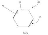
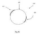
システムの要求を満たすために、リピータアンテナの第1と第2のアンテナビームは、多かれ少なかれ任意に選択された角度αにより分離される。これを成し遂げるために、リピータアンテナ250の2つの実施例の上面が示されている図4aと図4bに示されているように、リピータアンテナは第1のアンテナ要素410と第2のアンテナ要素420とを有し、それらは面430に設置されている。ここで、その面に沿った2つのアンテナ要素間の距離はこれらアンテナ要素間の最短距離よりも長くなっている。言い換えると、アンテナ要素が配置される面は曲面であるか、或いは、曲がっている。そのようなものとしてアンテナ要素は、図4aと図4bに夫々示されているように、その面の形状を曲面的に或いは曲がって辿ることができるか、或いは、実質的には直線であっても良い。 To meet the system requirements, the first and second antenna beams of the repeater antenna are separated by an angle α that is more or less arbitrarily selected. To accomplish this, the repeater antenna comprises a
リピータアンテナのデザインを詳細に説明する前に、リピータアンテナのもう1つの側面について言及しておく。即ち、リピータアンテナは能動型アンテナでも良いし、或いは、受動型アンテナでも良い。言い換えると、リピータアンテナは1つのビームにおいて受信した信号をそのアンテナのもう1つのビームによって送信されるように受動的に中継するか、或いは、受信信号をその再送信前に増幅することができる。1つの同じリピータアンテナは事実、両方のアプリケーションのために用いられる。もし、そのリピータが受動モードにおいて用いられるなら、各ビームへの入出力ポートは単純に互いに接続されるだけである。もし、そのリピータが能動モードにおいて用いられるなら、同じポートは外部増幅装置を介して互いに接続される。 Before describing the repeater antenna design in detail, another aspect of the repeater antenna will be mentioned. That is, the repeater antenna may be an active antenna or a passive antenna. In other words, the repeater antenna can either passively relay the signal received in one beam to be transmitted by the other beam of that antenna, or amplify the received signal before its retransmission. One identical repeater antenna is in fact used for both applications. If the repeater is used in passive mode, the input / output ports to each beam are simply connected to each other. If the repeater is used in active mode, the same ports are connected to each other via an external amplifier.
当然ことであるが、リピータアンテナはまた最初から能動型或いは受動型リピータとしてデザインされても良い。 Of course, repeater antennas may also be designed from the outset as active or passive repeaters.
さて、リピータアンテナのより正確なデザインのいくつかの例に戻って説明すると、そのアンテナは必ずしも必要ではないが適切に所謂“パッチアンテナ”として設計されている。そのようなアンテナは、放射要素として、通常、この技術分野ではそのようなものとしては公知の方法で、非導電層或いは基板上に形成された導電材のパッチを有している。“パッチ”タイプのアンテナはまた、接地平面、即ち、誘電材により放射要素からは離間された導電材の別の平面を、通常は別の物理層の形で有している。しかしながら、前記誘電材の層はただの空気の層であっても良い。 Now, returning to some examples of a more accurate design of a repeater antenna, the antenna is not necessarily required, but is appropriately designed as a so-called “patch antenna”. Such an antenna has a radiating element, typically a patch of conductive material formed on a non-conductive layer or substrate in a manner known as such in the art. “Patch” type antennas also have a ground plane, ie another plane of conductive material separated from the radiating element by a dielectric material, usually in the form of another physical layer. However, the dielectric layer may be just a layer of air.
また、そのパッチアンテナは給電ネットワークを有しており、その給電ネットワークにより放射要素がそのアンテナの入出力ポートに接続され、互いに対してもおそらく接続され、そして、適用可能である場合には、例えば、移相器のようなアンテナの別の要素に対して接続される。 The patch antenna also has a feeding network, where the radiating elements are connected to the input and output ports of the antenna, possibly connected to each other, and if applicable, for example, Connected to another element of the antenna, such as a phase shifter.
給電ネットワークは、放射要素或と同じ導電層に形成されても良いし、或いは、例えば接地平面の貫通孔により放射要素に接続された分離されたネットワークとして形成されても良い。 The feed network may be formed in the same conductive layer as the radiating element or may be formed as a separate network connected to the radiating element, for example by a through hole in the ground plane.
放射要素に対する給電ネットワークの設計は、例えば、複数の放射要素を接続して、所謂、進行波アンテナを形成したり、その給電ネットワークをバトラマトリクスアンテナとしたり、或いは、個々に給電ネットワークを備えた個々のアンテナパッチがあるようにさえするなど数多くの原理から選択することができる。 The design of the feeding network for the radiating element is, for example, by connecting a plurality of radiating elements to form a so-called traveling wave antenna, using the feeding network as a Butler matrix antenna, or individually including a feeding network. There are many principles to choose from, such as even having an antenna patch.
図5には進行波アンテナ500の例が示されている。アンテナ500は、少なくとも第1の放射要素511と第2の放射要素512を備え、それらが互いから中心距離Dを保って直列に配列されている。 An example of traveling
その放射要素は互いに直列に接続されているので、第1の“終端”要素と第2の“終端”要素とがあり、それらに対してアンテナ500の入出力ポート522、523が取り付けられる。 Since the radiating elements are connected in series with each other, there are a first “termination” element and a second “termination” element to which the input /
図5に示されているように、アンテナ500は第1のアンテナビーム532と第2のアンテナビーム533とがあり、それらは各々、アンテナポート522、523の1つと関係付けられる。このことは第1のビーム532が第1のポート522にアクセスすることにより用いられ、同様にして、第2のビーム533が第2のポート523と関係付けられる。そのビーム間の角度は、そのアンテナのアンテナ要素間の中心距離Dにより決定される。 As shown in FIG. 5, the
また、図5から分かるように、進行波アンテナの2つのアンテナビームはアンテナに垂直な方向に伸びる仮想線に関して、互いの“鏡像”となる。従って、これら2つのビームはしばしば“+(プラス)”或いは“−(マイナス)”方向として言及される。 Further, as can be seen from FIG. 5, the two antenna beams of the traveling wave antenna become “mirror images” of each other with respect to the imaginary line extending in the direction perpendicular to the antenna. Thus, these two beams are often referred to as “+ (plus)” or “− (minus)” directions.
バトラマトリクスアンテナは、この技術分野では非常に良く知られたものなので、ここではその説明を簡単に留める。バトラマトリクスアンテナはN個の入出力ポートを有し、N個のアンテナビームを生成する。そのバトラマトリクスの内部にあるネットワークによって、複数の入出力ポートのいずれか1つに入力される信号は全てのアンテナポートで同じ振幅と、(アンテナ)ポートからポートへと線形位相プログレッションを作り出す。もし、そのアンテナポートが順に同じ間隔が設けられた線形アンテナアレイに接続されるなら、1つのアンテナビームが各入出力ポートに対して形成される。 Since the Butler matrix antenna is very well known in the art, its description will be briefly described here. The Butler matrix antenna has N input / output ports and generates N antenna beams. Due to the network inside the Butler matrix, the signal input to any one of the input / output ports creates the same amplitude at all antenna ports and linear phase progression from (antenna) port to port. If the antenna port is connected in turn to a linear antenna array with the same spacing, one antenna beam is formed for each input / output port.
内部ネットワークは移相器とハイブリッドを有し、2つ以上の入出力ポートを外部接続することにより、そのアンテナ図は動かされ、広げられ、或いは、変更されたサイドローブレベルに与えられる。 The internal network has a phase shifter and a hybrid, and by externally connecting two or more input / output ports, the antenna diagram can be moved, widened, or applied to a modified sidelobe level.
図6はリピータアンテナの好適な実施例600を示している。ここで分かるように、そのアンテナは曲げられた面620、この場合には、八つの面をもつ或いは八面体を有している。前記本体部は細長い形をしている、即ち、縦方向(y)の拡がりと、横方向(x)の拡がりとをもち、この場合、縦方向への拡がりは横方向への拡がりより大きい。そして、八面体のフラットな面夫々にはアンテナ要素6211−621Nをもつ数多くのアレイ621−623が構成されており、360度のカバレッジを達成している。当然ことであるが、アンテナ本体部は六角形でもよく、或いは、異なる方向に複数の面をもつ何らかの他の形でもよく、或いは、図4に示されているように円筒形でも良い。FIG. 6 shows a
図6に示されているように、アンテナアレイ621−623は1次元アレイ、即ち、リピータアンテナの拡がりの前記方向の1つ、この場合には、縦方向(y)の拡がりと一致するように構成された縦列状のアレイである。従って、以前に述べた第1のアンテナ要素と第2のアンテナ要素とは、この実施例では、複数のアンテナ要素を有する各アレイの一部である。 As shown in FIG. 6, the antenna array 621-623 is a one-dimensional array, ie, coincides with one of the above-mentioned directions of repeater antenna spread, in this case the longitudinal (y) spread. It is a configured columnar array. Accordingly, the previously described first antenna element and second antenna element are part of each array having a plurality of antenna elements in this embodiment.
このアレイは図6に示されているように、1次元アレイで良いが、それは2次元アレイでも良い。この2つの次元はリピータアンテナの2つの主要な拡がりの方向と実質的に一致するように配置される。 This array can be a one-dimensional array, as shown in FIG. 6, but it can also be a two-dimensional array. These two dimensions are arranged to substantially coincide with the two major spreading directions of the repeater antenna.
図7は本発明に従うリピータアンテナの他の実施例700を示している。 FIG. 7 shows another
以前に示したアンテナと類似して、アンテナ700は第1の複数の放射要素710、第2の複数の放射要素720をもっており、ここでは八角形の側面にある縦列アレイとして示されている。前記複数の放射要素の両方は2次元ビーム形成ネットワークに接続され、そのネットワークにより、複数のビーム或いは放射ダイヤグラムが方位角方向(水平方向“H”)と仰角方向(垂直方向“V”)の両方に生成される。従って、アンテナ700により、別々のビームがセル内の数多くの関連のある領域に対して形成され、例えば、基地局と上述したような遮られた領域“A”とをカバーできる。 Similar to the antenna previously shown, the
図7に示されたように、アンテナ700は、この場合は、八角形であるが、円筒形アンテナであり、既に述べたように、2次元、つまり、仰角と方位角方向の両方に、ビーム形成ネットワークが備えられ、複数のビームが仰角方向に形成される。 As shown in FIG. 7, the
一例として、アンテナ700は個々の縦列アレイに別々の給電ネットワークで給電してもよく、垂直方向の給電ネットワーク720の出力ポートからの信号は方位角方向の2つ以上のビーム形成ネットワーク730を用いて結合される。 As an example,
ビーム形成はここでは、垂直方向と水平(方位角)方向の両方で実行される。また、較正は縦列だけを基本として、即ち、縦列間で、その縦列内の固定されたビーム形成ネットワークを用いて実施される。 Beam forming here is performed both in the vertical and horizontal (azimuth) directions. Also, calibration is performed on a column-by-column basis, i.e., between columns, using a fixed beamforming network within that column.
ビーム形成ネットワーク(例えば、バトラマトリクス)が(二重偏向アンテナ要素の場合)2つの直交偏向の1つ或いは両方に適用され、仰角方向に異なる数のアンテナ要素を接続することができる。 A beam forming network (e.g., a Butler matrix) can be applied to one or both of the two orthogonal deflections (in the case of double deflection antenna elements) to connect different numbers of antenna elements in the elevation direction.
本発明は上述の実施例に限定されるものではなく、添付の請求の範囲の中で自由に変更することができる。例えば、異なる偏向が異なるアンテナビームで用いられても良く、或いは、1つ以上のアンテナ要素が二重偏向されても良い。 The invention is not limited to the embodiments described above, but may be varied freely within the scope of the appended claims. For example, different deflections may be used with different antenna beams, or one or more antenna elements may be double deflected.
放射要素或いはアンテナ要素は典型的には、所謂パッチアンテナであるが、当業者には公知であるようなダイポールや何か他のタイプの放射要素でも良い。 The radiating element or antenna element is typically a so-called patch antenna, but may be a dipole or some other type of radiating element as is known to those skilled in the art.
所望のカバレッジを達成するためにリピータアンテナはそれが生成する任意の数のビームを利用できることも指摘しておくべきである。例えば、4つのビームをもつリピータアンテナでは1つのビームを用いて受信し、異なる方向に向けられた2つのビームを用いてそれが受信したデータを再送信できる。 It should also be pointed out that a repeater antenna can utilize any number of beams that it generates to achieve the desired coverage. For example, a repeater antenna with four beams can receive using one beam and retransmit the data it receives using two beams directed in different directions.
Claims (7)
Translated fromJapanese前記リピータアンテナは、少なくとも第1のアンテナ要素(410)と第2のアンテナ要素(420)と前記アンテナ要素に対する給電ネットワークとをもち、
前記アンテナ要素が第1のアンテナビーム(260)と第2のアンテナビーム(270)とを生じさせ、
前記第1のアンテナビームが前記リピータアンテナを前記第1の無線ユニットに接続するために用いられ、そして、前記第2のアンテナビームが前記リピータアンテナを前記第2の無線ユニットに接続するために用いられ、
前記第1のアンテナ要素と前記第2のアンテナ要素とがある面(430,620)に設置され、
前記面に沿った前記2つのアンテナ要素間の距離が前記2つのアンテナ要素間の最短距離よりも長いことを特徴とするリピータアンテナ。A repeater antenna used in a communication system in the microwave region and intended for connection from a first radio unit (120) at a first installation location to a second radio unit at a second installation location (A) There,
The repeater antenna has at least a first antenna element (410), a second antenna element (420) and a feeding network for the antenna element;
The antenna element produces a first antenna beam (260) and a second antenna beam (270);
The first antenna beam is used to connect the repeater antenna to the first radio unit, and the second antenna beam is used to connect the repeater antenna to the second radio unit. And
The first antenna element and the second antenna element are installed on a plane (430, 620);
A repeater antenna, wherein a distance between the two antenna elements along the plane is longer than a shortest distance between the two antenna elements.
前記アンテナ要素のアレイは、前記リピータアンテナの拡がりの前記方向の1つと一致するように構成される1次元アレイであることを特徴とする請求項2に記載のリピータアンテナ。The repeater antenna has a horizontal (x) and vertical (y) spread,
The repeater antenna of claim 2, wherein the array of antenna elements is a one-dimensional array configured to coincide with one of the directions of the repeater antenna spread.
前記アンテナ要素のアレイは2次元アレイであり、
前記2つの次元は前記リピータアンテナの拡がりの前記方向の1つと実質的に一致するように構成されることを特徴とする請求項2に記載のリピータアンテナ。The repeater antenna has a horizontal (x) and vertical (y) spread,
The array of antenna elements is a two-dimensional array;
The repeater antenna of claim 2, wherein the two dimensions are configured to substantially coincide with one of the directions of the repeater antenna spread.
前記アンテナはさらに、誘電材により前記アンテナ要素とは離間した接地平面を有することを特徴とする請求項1乃至4のいずれか1項に記載のリピータアンテナ。The antenna element is substantially planar and formed on a sheet of conductive material;
The repeater antenna according to any one of claims 1 to 4, wherein the antenna further includes a ground plane separated from the antenna element by a dielectric material.
Applications Claiming Priority (1)
| Application Number | Priority Date | Filing Date | Title |
|---|---|---|---|
| PCT/SE2005/001078WO2007004927A1 (en) | 2005-07-04 | 2005-07-04 | An improved repeater antenna |
Publications (1)
| Publication Number | Publication Date |
|---|---|
| JP2008545326Atrue JP2008545326A (en) | 2008-12-11 |
Family
ID=37604698
Family Applications (1)
| Application Number | Title | Priority Date | Filing Date |
|---|---|---|---|
| JP2008519210APendingJP2008545326A (en) | 2005-07-04 | 2005-07-04 | Improved repeater antenna |
Country Status (6)
| Country | Link |
|---|---|
| US (1) | US20080200116A1 (en) |
| EP (1) | EP1900113A4 (en) |
| JP (1) | JP2008545326A (en) |
| CN (1) | CN101218762B (en) |
| MX (1) | MX2007015713A (en) |
| WO (1) | WO2007004927A1 (en) |
Families Citing this family (5)
| Publication number | Priority date | Publication date | Assignee | Title |
|---|---|---|---|---|
| US10862575B2 (en) | 2016-03-04 | 2020-12-08 | Netgear, Inc. | Compact passive repeater |
| US11018416B2 (en) | 2017-02-03 | 2021-05-25 | Commscope Technologies Llc | Small cell antennas suitable for MIMO operation |
| WO2018156445A1 (en)* | 2017-02-21 | 2018-08-30 | 3M Innovative Properties Company | Passive repeater device, microwave network, and method of designing a repeater device |
| US10530440B2 (en)* | 2017-07-18 | 2020-01-07 | Commscope Technologies Llc | Small cell antennas suitable for MIMO operation |
| JP7293066B2 (en)* | 2019-09-20 | 2023-06-19 | 株式会社日立製作所 | antenna device |
Citations (8)
| Publication number | Priority date | Publication date | Assignee | Title |
|---|---|---|---|---|
| JPH09172317A (en)* | 1995-07-18 | 1997-06-30 | Lucent Technol Inc | Multi-layer integrated power distribution device |
| JPH09200115A (en)* | 1996-01-23 | 1997-07-31 | Toshiba Corp | Antenna directivity control method for wireless base station in wireless communication system and variable directivity antenna |
| JPH11251823A (en)* | 1998-03-05 | 1999-09-17 | Sumitomo Electric Ind Ltd | Scanning antenna |
| JP2001077739A (en)* | 1999-07-20 | 2001-03-23 | Andrew Corp | Flank-to-flank repeater and its operating method |
| JP2003332967A (en)* | 1997-03-03 | 2003-11-21 | Toshiba Corp | Satellite broadcast system, terrestrial transmitter, gap filler device, broadcast receiver, and satellite broadcast method |
| JP2005020368A (en)* | 2003-06-26 | 2005-01-20 | Nippon Telegr & Teleph Corp <Ntt> | Multi-beam antenna |
| JP2006514488A (en)* | 2003-02-26 | 2006-04-27 | イーエムエス テクノロジーズ インコーポレイテッド | Cellular signal enhancer |
| JP2008545329A (en)* | 2005-07-04 | 2008-12-11 | テレフオンアクチーボラゲット エル エム エリクソン(パブル) | Improved repeater antenna used for point-to-point applications |
Family Cites Families (8)
| Publication number | Priority date | Publication date | Assignee | Title |
|---|---|---|---|---|
| US4843403A (en)* | 1987-07-29 | 1989-06-27 | Ball Corporation | Broadband notch antenna |
| US5642358A (en)* | 1994-04-08 | 1997-06-24 | Ericsson Inc. | Multiple beamwidth phased array |
| US5861844A (en)* | 1994-11-29 | 1999-01-19 | Qualcomm Incorporated | Method and apparatus for providing redundant coverage within a cellular communication system |
| FR2766995B1 (en)* | 1997-07-31 | 1999-10-01 | Alsthom Cge Alcatel | ACTIVE REPEATER FOR TRANSMISSION SYSTEM |
| CA2397430A1 (en) | 2000-01-14 | 2001-07-19 | Breck W. Lovinggood | Repeaters for wireless communication systems |
| US7065384B2 (en)* | 2001-08-21 | 2006-06-20 | Hrl Laboratories, Llc | Networked and field addressable distributed antenna system |
| GB0200237D0 (en)* | 2002-01-07 | 2002-02-20 | Imec Inter Uni Micro Electr | Wireless cellular network architecture |
| US7009573B2 (en)* | 2003-02-10 | 2006-03-07 | Calamp Corp. | Compact bidirectional repeaters for wireless communication systems |
- 2005
- 2005-07-04JPJP2008519210Apatent/JP2008545326A/enactivePending
- 2005-07-04USUS11/994,464patent/US20080200116A1/ennot_activeAbandoned
- 2005-07-04WOPCT/SE2005/001078patent/WO2007004927A1/enactiveApplication Filing
- 2005-07-04EPEP05755293Apatent/EP1900113A4/ennot_activeCeased
- 2005-07-04MXMX2007015713Apatent/MX2007015713A/enactiveIP Right Grant
- 2005-07-04CNCN200580050981XApatent/CN101218762B/ennot_activeExpired - Fee Related
Patent Citations (8)
| Publication number | Priority date | Publication date | Assignee | Title |
|---|---|---|---|---|
| JPH09172317A (en)* | 1995-07-18 | 1997-06-30 | Lucent Technol Inc | Multi-layer integrated power distribution device |
| JPH09200115A (en)* | 1996-01-23 | 1997-07-31 | Toshiba Corp | Antenna directivity control method for wireless base station in wireless communication system and variable directivity antenna |
| JP2003332967A (en)* | 1997-03-03 | 2003-11-21 | Toshiba Corp | Satellite broadcast system, terrestrial transmitter, gap filler device, broadcast receiver, and satellite broadcast method |
| JPH11251823A (en)* | 1998-03-05 | 1999-09-17 | Sumitomo Electric Ind Ltd | Scanning antenna |
| JP2001077739A (en)* | 1999-07-20 | 2001-03-23 | Andrew Corp | Flank-to-flank repeater and its operating method |
| JP2006514488A (en)* | 2003-02-26 | 2006-04-27 | イーエムエス テクノロジーズ インコーポレイテッド | Cellular signal enhancer |
| JP2005020368A (en)* | 2003-06-26 | 2005-01-20 | Nippon Telegr & Teleph Corp <Ntt> | Multi-beam antenna |
| JP2008545329A (en)* | 2005-07-04 | 2008-12-11 | テレフオンアクチーボラゲット エル エム エリクソン(パブル) | Improved repeater antenna used for point-to-point applications |
Also Published As
| Publication number | Publication date |
|---|---|
| WO2007004927A1 (en) | 2007-01-11 |
| US20080200116A1 (en) | 2008-08-21 |
| EP1900113A1 (en) | 2008-03-19 |
| CN101218762A (en) | 2008-07-09 |
| CN101218762B (en) | 2012-07-18 |
| EP1900113A4 (en) | 2012-02-15 |
| MX2007015713A (en) | 2008-02-21 |
Similar Documents
| Publication | Publication Date | Title |
|---|---|---|
| US12199715B2 (en) | Small cell beam-forming antennas | |
| CN108432088B (en) | Phased array antenna with sub-arrays | |
| EP3218962B1 (en) | Array antennas including non-uniform antenna elements | |
| EP1900063B1 (en) | An improved repeater antenna for use in point-to-point applications | |
| US20100127949A1 (en) | Mobile Communication base station antenna | |
| US20240047861A1 (en) | Small cell beamforming antennas suitable for use with 5g beamforming radios and related base stations | |
| CN115461933A (en) | Active antenna system | |
| JP7196930B2 (en) | Radio repeater and communication system | |
| KR20080028408A (en) | Improved repeater antenna | |
| JP2008545326A (en) | Improved repeater antenna | |
| US12294430B2 (en) | Signal processing device and base station antenna | |
| JP3822607B2 (en) | Array antenna | |
| US7280084B2 (en) | Antenna system for generating and utilizing several small beams from several wide-beam antennas | |
| RU2562756C1 (en) | Scanning antenna array, basic station, wireless communication network and method for formation of directivity pattern | |
| KR102428139B1 (en) | Uniform circular array antenna for milimeter wave | |
| KR102092601B1 (en) | Radiation pattern for modified antenna for shadow zone of of radio wave | |
| WO2007004930A1 (en) | An improved repeater antenna for use in point-to-point applications |
Legal Events
| Date | Code | Title | Description |
|---|---|---|---|
| A977 | Report on retrieval | Free format text:JAPANESE INTERMEDIATE CODE: A971007 Effective date:20100830 | |
| A131 | Notification of reasons for refusal | Free format text:JAPANESE INTERMEDIATE CODE: A131 Effective date:20101224 | |
| A601 | Written request for extension of time | Free format text:JAPANESE INTERMEDIATE CODE: A601 Effective date:20110317 | |
| A602 | Written permission of extension of time | Free format text:JAPANESE INTERMEDIATE CODE: A602 Effective date:20110325 | |
| A521 | Request for written amendment filed | Free format text:JAPANESE INTERMEDIATE CODE: A523 Effective date:20110408 | |
| A02 | Decision of refusal | Free format text:JAPANESE INTERMEDIATE CODE: A02 Effective date:20120130 |