JP2008541878A - Electrothermal disc treatment - Google Patents
Electrothermal disc treatmentDownload PDFInfo
- Publication number
- JP2008541878A JP2008541878AJP2008513747AJP2008513747AJP2008541878AJP 2008541878 AJP2008541878 AJP 2008541878AJP 2008513747 AJP2008513747 AJP 2008513747AJP 2008513747 AJP2008513747 AJP 2008513747AJP 2008541878 AJP2008541878 AJP 2008541878A
- Authority
- JP
- Japan
- Prior art keywords
- treatment site
- transfer device
- heat transfer
- heat
- applying heat
- Prior art date
- Legal status (The legal status is an assumption and is not a legal conclusion. Google has not performed a legal analysis and makes no representation as to the accuracy of the status listed.)
- Pending
Links
- 238000012546transferMethods0.000claimsabstractdescription110
- 238000010438heat treatmentMethods0.000claimsabstractdescription99
- 238000000034methodMethods0.000claimsabstractdescription38
- 239000004020conductorSubstances0.000claimsdescription26
- 230000007246mechanismEffects0.000claimsdescription25
- 239000012530fluidSubstances0.000claimsdescription15
- FAPWRFPIFSIZLT-UHFFFAOYSA-MSodium chlorideChemical compound[Na+].[Cl-]FAPWRFPIFSIZLT-UHFFFAOYSA-M0.000claimsdescription8
- 239000011780sodium chlorideSubstances0.000claimsdescription8
- 238000012544monitoring processMethods0.000claimsdescription6
- 238000005452bendingMethods0.000claimsdescription5
- 230000005611electricityEffects0.000claimsdescription5
- 230000006698inductionEffects0.000claimsdescription2
- 230000007850degenerationEffects0.000abstractdescription7
- 210000001519tissueAnatomy0.000description18
- 208000002193PainDiseases0.000description16
- 230000007170pathologyEffects0.000description9
- 210000005036nerveAnatomy0.000description8
- 208000008035Back PainDiseases0.000description7
- 238000004925denaturationMethods0.000description7
- 230000036425denaturationEffects0.000description7
- 230000006870functionEffects0.000description6
- 208000008930Low Back PainDiseases0.000description5
- 230000002638denervationEffects0.000description4
- 239000000463materialSubstances0.000description4
- 239000000523sampleSubstances0.000description4
- 208000024891symptomDiseases0.000description4
- 206010070834SensitisationDiseases0.000description3
- 239000000975dyeSubstances0.000description3
- 210000000929nociceptorAnatomy0.000description3
- 230000001575pathological effectEffects0.000description3
- 230000008313sensitizationEffects0.000description3
- 238000001356surgical procedureMethods0.000description3
- 206010019909HerniaDiseases0.000description2
- 206010061246Intervertebral disc degenerationDiseases0.000description2
- 208000034693LacerationDiseases0.000description2
- 230000008901benefitEffects0.000description2
- 230000006835compressionEffects0.000description2
- 238000007906compressionMethods0.000description2
- 239000002872contrast mediaSubstances0.000description2
- 239000000835fiberSubstances0.000description2
- 238000002594fluoroscopyMethods0.000description2
- 230000030214innervationEffects0.000description2
- 238000009413insulationMethods0.000description2
- 239000002184metalSubstances0.000description2
- 230000004048modificationEffects0.000description2
- 238000012986modificationMethods0.000description2
- 210000000944nerve tissueAnatomy0.000description2
- 108091008700nociceptorsProteins0.000description2
- 230000000149penetrating effectEffects0.000description2
- 230000008569processEffects0.000description2
- 230000004044responseEffects0.000description2
- 238000012800visualizationMethods0.000description2
- 102000008186CollagenHuman genes0.000description1
- 108010035532CollagenProteins0.000description1
- 108090000790EnzymesProteins0.000description1
- 102000004190EnzymesHuman genes0.000description1
- 239000004642PolyimideSubstances0.000description1
- 208000027418Wounds and injuryDiseases0.000description1
- 238000002679ablationMethods0.000description1
- 230000003213activating effectEffects0.000description1
- 210000003484anatomyAnatomy0.000description1
- 239000002260anti-inflammatory agentSubstances0.000description1
- 229940124599anti-inflammatory drugDrugs0.000description1
- 238000013459approachMethods0.000description1
- 238000011882arthroplastyMethods0.000description1
- 230000009286beneficial effectEffects0.000description1
- 210000004204blood vesselAnatomy0.000description1
- 244000309466calfSpecies0.000description1
- 230000001684chronic effectEffects0.000description1
- 229920001436collagenPolymers0.000description1
- 229940039231contrast mediaDrugs0.000description1
- 238000011461current therapyMethods0.000description1
- 230000006378damageEffects0.000description1
- 230000003412degenerative effectEffects0.000description1
- 238000009792diffusion processMethods0.000description1
- 230000001079digestive effectEffects0.000description1
- 229940079593drugDrugs0.000description1
- 239000003814drugSubstances0.000description1
- 238000002651drug therapyMethods0.000description1
- 230000000694effectsEffects0.000description1
- 230000000763evoking effectEffects0.000description1
- 230000004927fusionEffects0.000description1
- 230000001939inductive effectEffects0.000description1
- 238000002347injectionMethods0.000description1
- 239000007924injectionSubstances0.000description1
- 239000012212insulatorSubstances0.000description1
- 210000002414legAnatomy0.000description1
- 230000003902lesionEffects0.000description1
- 239000007788liquidSubstances0.000description1
- 230000004807localizationEffects0.000description1
- 238000002595magnetic resonance imagingMethods0.000description1
- 238000007726management methodMethods0.000description1
- 210000004126nerve fiberAnatomy0.000description1
- 230000000926neurological effectEffects0.000description1
- HLXZNVUGXRDIFK-UHFFFAOYSA-Nnickel titaniumChemical compound[Ti].[Ti].[Ti].[Ti].[Ti].[Ti].[Ti].[Ti].[Ti].[Ti].[Ti].[Ni].[Ni].[Ni].[Ni].[Ni].[Ni].[Ni].[Ni].[Ni].[Ni].[Ni].[Ni].[Ni].[Ni]HLXZNVUGXRDIFK-UHFFFAOYSA-N0.000description1
- 229910001000nickel titaniumInorganic materials0.000description1
- 239000013307optical fiberSubstances0.000description1
- 238000002559palpationMethods0.000description1
- 230000035515penetrationEffects0.000description1
- 239000004033plasticSubstances0.000description1
- 229920000728polyesterPolymers0.000description1
- 229920001721polyimidePolymers0.000description1
- 230000009467reductionEffects0.000description1
- 230000008439repair processEffects0.000description1
- 239000000565sealantSubstances0.000description1
- 230000035945sensitivityEffects0.000description1
- 238000004513sizingMethods0.000description1
- 230000007480spreadingEffects0.000description1
- 238000002626targeted therapyMethods0.000description1
- 230000002277temperature effectEffects0.000description1
- 238000002560therapeutic procedureMethods0.000description1
- 238000000015thermotherapyMethods0.000description1
- 230000001550time effectEffects0.000description1
- 230000026683transductionEffects0.000description1
- 238000010361transductionMethods0.000description1
- 210000000689upper legAnatomy0.000description1
- 230000000007visual effectEffects0.000description1
Images


Classifications
- A—HUMAN NECESSITIES
- A61—MEDICAL OR VETERINARY SCIENCE; HYGIENE
- A61B—DIAGNOSIS; SURGERY; IDENTIFICATION
- A61B18/00—Surgical instruments, devices or methods for transferring non-mechanical forms of energy to or from the body
- A61B18/04—Surgical instruments, devices or methods for transferring non-mechanical forms of energy to or from the body by heating
- A61B18/12—Surgical instruments, devices or methods for transferring non-mechanical forms of energy to or from the body by heating by passing a current through the tissue to be heated, e.g. high-frequency current
- A61B18/14—Probes or electrodes therefor
- A61B18/148—Probes or electrodes therefor having a short, rigid shaft for accessing the inner body transcutaneously, e.g. for neurosurgery or arthroscopy
- A—HUMAN NECESSITIES
- A61—MEDICAL OR VETERINARY SCIENCE; HYGIENE
- A61B—DIAGNOSIS; SURGERY; IDENTIFICATION
- A61B18/00—Surgical instruments, devices or methods for transferring non-mechanical forms of energy to or from the body
- A61B2018/00053—Mechanical features of the instrument of device
- A61B2018/00214—Expandable means emitting energy, e.g. by elements carried thereon
- A61B2018/00267—Expandable means emitting energy, e.g. by elements carried thereon having a basket shaped structure
- A—HUMAN NECESSITIES
- A61—MEDICAL OR VETERINARY SCIENCE; HYGIENE
- A61B—DIAGNOSIS; SURGERY; IDENTIFICATION
- A61B18/00—Surgical instruments, devices or methods for transferring non-mechanical forms of energy to or from the body
- A61B2018/00315—Surgical instruments, devices or methods for transferring non-mechanical forms of energy to or from the body for treatment of particular body parts
- A61B2018/00434—Neural system
- A61B2018/0044—Spinal cord
- A—HUMAN NECESSITIES
- A61—MEDICAL OR VETERINARY SCIENCE; HYGIENE
- A61B—DIAGNOSIS; SURGERY; IDENTIFICATION
- A61B18/00—Surgical instruments, devices or methods for transferring non-mechanical forms of energy to or from the body
- A61B18/04—Surgical instruments, devices or methods for transferring non-mechanical forms of energy to or from the body by heating
- A61B18/12—Surgical instruments, devices or methods for transferring non-mechanical forms of energy to or from the body by heating by passing a current through the tissue to be heated, e.g. high-frequency current
- A61B18/14—Probes or electrodes therefor
- A61B2018/1405—Electrodes having a specific shape
- A61B2018/1407—Loop
- A—HUMAN NECESSITIES
- A61—MEDICAL OR VETERINARY SCIENCE; HYGIENE
- A61B—DIAGNOSIS; SURGERY; IDENTIFICATION
- A61B18/00—Surgical instruments, devices or methods for transferring non-mechanical forms of energy to or from the body
- A61B18/04—Surgical instruments, devices or methods for transferring non-mechanical forms of energy to or from the body by heating
- A61B18/12—Surgical instruments, devices or methods for transferring non-mechanical forms of energy to or from the body by heating by passing a current through the tissue to be heated, e.g. high-frequency current
- A61B18/14—Probes or electrodes therefor
- A61B2018/1405—Electrodes having a specific shape
- A61B2018/1425—Needle
- A61B2018/143—Needle multiple needles
- A—HUMAN NECESSITIES
- A61—MEDICAL OR VETERINARY SCIENCE; HYGIENE
- A61B—DIAGNOSIS; SURGERY; IDENTIFICATION
- A61B18/00—Surgical instruments, devices or methods for transferring non-mechanical forms of energy to or from the body
- A61B18/04—Surgical instruments, devices or methods for transferring non-mechanical forms of energy to or from the body by heating
- A61B18/12—Surgical instruments, devices or methods for transferring non-mechanical forms of energy to or from the body by heating by passing a current through the tissue to be heated, e.g. high-frequency current
- A61B18/14—Probes or electrodes therefor
- A61B2018/1405—Electrodes having a specific shape
- A61B2018/1435—Spiral
- A—HUMAN NECESSITIES
- A61—MEDICAL OR VETERINARY SCIENCE; HYGIENE
- A61B—DIAGNOSIS; SURGERY; IDENTIFICATION
- A61B18/00—Surgical instruments, devices or methods for transferring non-mechanical forms of energy to or from the body
- A61B18/04—Surgical instruments, devices or methods for transferring non-mechanical forms of energy to or from the body by heating
- A61B18/12—Surgical instruments, devices or methods for transferring non-mechanical forms of energy to or from the body by heating by passing a current through the tissue to be heated, e.g. high-frequency current
- A61B18/14—Probes or electrodes therefor
- A61B2018/1467—Probes or electrodes therefor using more than two electrodes on a single probe
- A—HUMAN NECESSITIES
- A61—MEDICAL OR VETERINARY SCIENCE; HYGIENE
- A61B—DIAGNOSIS; SURGERY; IDENTIFICATION
- A61B18/00—Surgical instruments, devices or methods for transferring non-mechanical forms of energy to or from the body
- A61B18/04—Surgical instruments, devices or methods for transferring non-mechanical forms of energy to or from the body by heating
- A61B18/12—Surgical instruments, devices or methods for transferring non-mechanical forms of energy to or from the body by heating by passing a current through the tissue to be heated, e.g. high-frequency current
- A61B18/14—Probes or electrodes therefor
- A61B2018/1475—Electrodes retractable in or deployable from a housing
- A—HUMAN NECESSITIES
- A61—MEDICAL OR VETERINARY SCIENCE; HYGIENE
- A61B—DIAGNOSIS; SURGERY; IDENTIFICATION
- A61B2218/00—Details of surgical instruments, devices or methods for transferring non-mechanical forms of energy to or from the body
- A61B2218/001—Details of surgical instruments, devices or methods for transferring non-mechanical forms of energy to or from the body having means for irrigation and/or aspiration of substances to and/or from the surgical site
- A61B2218/002—Irrigation
Landscapes
- Health & Medical Sciences (AREA)
- Engineering & Computer Science (AREA)
- Life Sciences & Earth Sciences (AREA)
- Surgery (AREA)
- Biomedical Technology (AREA)
- Molecular Biology (AREA)
- Nuclear Medicine, Radiotherapy & Molecular Imaging (AREA)
- Otolaryngology (AREA)
- Physics & Mathematics (AREA)
- Neurosurgery (AREA)
- Neurology (AREA)
- Heart & Thoracic Surgery (AREA)
- Medical Informatics (AREA)
- Plasma & Fusion (AREA)
- Animal Behavior & Ethology (AREA)
- General Health & Medical Sciences (AREA)
- Public Health (AREA)
- Veterinary Medicine (AREA)
- Surgical Instruments (AREA)
- Thermotherapy And Cooling Therapy Devices (AREA)
- Prostheses (AREA)
Abstract
Translated fromJapaneseDescription
Translated fromJapanese本発明は、電熱椎間板治療に関する。 The present invention relates to electrothermal disc treatment.
椎間板起因の腰痛は、椎間板内部の亀裂によって特徴付けられる椎間板変性によって引き起こされると考えられる。椎間板自体が痛みの原因になり得る証拠は、意識状態での患者からの痛み反応を惹起するために椎間板探針(disc probing)を行った研究によって証明されている。また、椎間板の痛みと、椎間板内の亀裂に合致した解剖学的変化との間に相関が見られる。 Disc-induced low back pain is thought to be caused by disc degeneration characterized by cracks within the disc. Evidence that the disc itself can cause pain is evidenced by studies that performed disc probing to elicit pain responses from patients in a conscious state. There is also a correlation between disc pain and anatomical changes consistent with a crack in the disc.
これらの研究で使用される主要な診断ツールは、椎間板造影法である。椎間板造影法では、椎間板内に食塩水及び造影剤を注入するために、針が椎間板内に挿入される。椎間板を加圧することによって、触診に類似した痛み反応が惹起される。造影剤は、椎間板の解剖学的構造を評価するために、蛍光透視法を使用して視覚化することができる。椎間板は、変性の程度を示すために1〜4のスケールで等級付けされ、数値が高くなるにしたがって変性の程度が大きくなる。 The primary diagnostic tool used in these studies is discography. In discography, a needle is inserted into the disc to inject saline and contrast media into the disc. By pressurizing the disc, a pain response similar to palpation is evoked. The contrast agent can be visualized using fluoroscopy to assess the anatomy of the disc. Intervertebral discs are graded on a scale of 1 to 4 to indicate the degree of degeneration, and the degree of degeneration increases as the value increases.
椎間板が変性の自然なプロセスを受けると、椎間板の構造及び生化学環境内で生じる変化が、椎間板上への重量の負荷パターンの変化をもたらすことがあり、また、侵害受容器神経繊維の鋭敏化(sensitization)をもたらすこともある。機械的及び神経的な変化の組合せが、慢性の椎間板起因の痛みをもたらす。 When the disc undergoes the natural process of degeneration, changes that occur within the disc structure and biochemical environment can result in changes in the weight loading pattern on the disc and also sensitize nociceptor nerve fibers. May cause (sensitization). The combination of mechanical and neurological changes results in chronic discogenic pain.
さまざまな研究者が、椎間板内部の侵害受容器の存在を実証している。椎間板が亀裂を生じると、椎間板の外側環内に成長する血管によって特徴付けられる修復プロセスがそれに続いて起こる。この血管新生(vascularization)と共に、神経支配(innervation)が生じる。この神経支配は、椎間板に関する通常の負荷条件下で、環内部の痛覚受容器の負荷をもたらし、痛覚受容器が椎間板起因の腰痛をもたらす。 Various researchers have demonstrated the existence of nociceptors inside the disc. When the intervertebral disc cracks, it is followed by a repair process characterized by blood vessels growing in the outer annulus of the disc. Along with this vascularization, innervation occurs. This innervation results in the loading of pain receptors within the annulus under normal loading conditions for the intervertebral disc, which results in discogenic low back pain.
椎間板起因の腰痛は、影響を受ける椎骨の周りの痛み、並びに臀部及び腿など、より広い領域への痛みの関連をもたらす。このタイプの痛みは、神経根痛(radicular pain)から区別可能であり、主として脚を下がってふくらはぎまで発する疼痛(shooting pain)である。神経根痛は、しばしば、神経根が脊椎から出るときに神経根のインピンジメント(impingement)により生じることがある。神経根のインピンジメントは、神経根が孔から出るときに神経根の圧迫及び鋭敏化をもたらす椎間板の隆起またはヘルニアによりしばしば生じる。椎間板起因及び神経根の痛みは、頚椎及び腰椎で生じることがある。椎間板起因及び神経根の症状は、しばしば同時に存在し、多くの患者において明確には区別できない。 Intervertebral disc low back pain results in pain around the affected vertebrae and pain in larger areas such as the hips and thighs. This type of pain is distinguishable from radial pain and is primarily pain that shoots down the leg to the calf. Nerve root pain is often caused by impingement of the nerve root as it exits the spine. Nerve root impingement is often caused by disc protuberances or hernias that cause compression and sensitization of the nerve root as it exits the foramen. Intervertebral disc origin and nerve root pain can occur in the cervical and lumbar vertebrae. Intervertebral disc causes and nerve root symptoms often exist simultaneously and are not clearly distinguishable in many patients.
腰痛のための各種電流治療は、保存管理(conservative management)(例えば、運動及び/または抗炎症薬療法)から、脊椎癒合(spine fusion)または関節固定、及び関節形成などの外科処置までの範囲がある。外科処置において、目標は、主として不快感を与える椎間板を取り除くこと及び椎間板が位置されている部分を癒合する、または椎間板を人工椎間板で置き換えることである。 Various current therapies for back pain range from conservative management (eg, exercise and / or anti-inflammatory drug therapy) to spinal fusion or joint fixation, and surgical procedures such as arthroplasty. is there. In a surgical procedure, the goal is to remove the intervertebral disc that is primarily uncomfortable and to heal the area where the disc is located, or to replace the disc with an artificial disc.
椎間板内温熱療法(Intradiscal Electrothermal Therapy:IDET)など非外科的代替方法が、少なくとも一部は、痛みのある椎間板を加熱することによって腰痛を緩和する方法として開発されている。痛みは、例えば外科手術を用いることなく椎間板内の病理神経組織を除神経する(すなわち殺す)ことによって緩和されることがある。より詳細には、亀裂の領域に加えられる熱が、亀裂の周りのコラーゲン構造を変更して変性(lesion)を生成する。主として、45℃よりも高い温度まで組織を加熱することが、神経組織を殺して変性を生成するために必要とされる。 Non-surgical alternatives such as Intradiscal Electrothermal Therapy (IDET) have been developed, at least in part, as a way to relieve back pain by heating the painful disc. Pain may be relieved, for example, by denervating (ie killing) pathologic nerve tissue in the disc without using surgery. More specifically, heat applied to the crack region alters the collagen structure around the crack, creating a lesion. Primarily, heating the tissue to a temperature above 45 ° C. is required to kill nerve tissue and produce degeneration.
IDETデバイスの従来技術例は、Sharkey(特許文献1)及びShah(特許文献2)に記載されるデバイス及び技法を含む。Sharkeyは、湾曲形状を取るように予備構成されたシースと、外部から椎間板内部にプローブを案内するための近位ハンドルとを含む椎間板デバイスを開示している。展開状態で、Shahのプローブは、プローブがシースの湾曲の方向で移動すると、及び/または環状壁と接触する際に核に向かって曲がって戻ると、椎間板内部で受動的に誘導される。また、Shahによって開示されるプローブは、ガイドワイヤを介して前進されることによって受動的に誘導されてもよく、このガイドワイヤは、ロープなど所定の形状を有し、シースから延出されている。 Prior art examples of IDET devices include the devices and techniques described in Sharkey (Patent Document 1) and Shah (Patent Document 2). Sharkey discloses an intervertebral disc device that includes a sheath preconfigured to assume a curved shape and a proximal handle for guiding the probe from the exterior into the intervertebral disc. In the deployed state, the Shah probe is passively guided inside the disc as the probe moves in the direction of the curvature of the sheath and / or bends back toward the nucleus when in contact with the annular wall. Also, the probe disclosed by Shah may be passively guided by being advanced through a guide wire, which has a predetermined shape, such as a rope, and extends from the sheath. .
Shahは、椎間板の病理に起因する椎間板起因の腰痛を治療するための椎間板内変性形成デバイスを開示している。Shahのデバイスは、機械、液圧、またはソレノイドアクチュエータを使用して椎間板内外に誘導することができる。Shahは、椎間板の内部に入ると、デバイスの遠位部分が、椎間板の核を通って誘導するように予備成形形状に受動的かつ弾性的に反跳することを開示する。
一般的な態様において、椎間板治療のためのデバイスは、椎間板内部の三次元治療部位に熱を供給するために椎間板の三次元体積を取り囲むように構成された伝熱デバイス(heat-delivery device)を含む。デバイスは、少なくとも二次元での伝熱デバイスの誘導を可能にするように構成された能動操縦機構(active steering mechanism)を含む。 In a general aspect, a device for intervertebral disc treatment includes a heat-delivery device configured to surround a three-dimensional volume of the intervertebral disc to provide heat to a three-dimensional treatment site within the intervertebral disc. Including. The device includes an active steering mechanism configured to allow guidance of the heat transfer device in at least two dimensions.
この態様の実装形態は、1またはそれ以上の後述の特徴を含む。例えば、操縦機構は、予備湾曲(pre-bent)ガイドワイヤと、ガイドワイヤをその長手方向軸の周りで回転させるためのノブとを含む。別法または追加として、操縦機構は、ガイドカテーテルと、ガイドカテーテルを誘導するための引張ワイヤまたはストリップとを含む。引張ワイヤまたはストリップを制御するためのさまざまな手段が開示される。 Implementations of this aspect include one or more of the features described below. For example, the steering mechanism includes a pre-bent guide wire and a knob for rotating the guide wire about its longitudinal axis. Alternatively or additionally, the steering mechanism includes a guide catheter and a puller wire or strip for guiding the guide catheter. Various means for controlling the puller wire or strip are disclosed.
ガイドカテーテルは、ガイドカテーテル内部に含まれる導電流体に電気を選択的に加えることによって誘導することができる。 The guide catheter can be guided by selectively applying electricity to the conductive fluid contained within the guide catheter.
伝熱デバイスは、椎間板内部で展開されたときに椎間板の三次元体積を取り囲むように伸張する加熱部材を含む。 The heat transfer device includes a heating member that expands to surround a three-dimensional volume of the disc when deployed within the disc.
加熱部材は、展開された状態で扇状に広がるバスケットの形状である、または展開されると巻き解かれる電極を含む。 The heating member includes an electrode that is in the shape of a basket that expands in a fan shape when unfolded or unrolled when unfolded.
別の一般的な態様において、椎間板を治療するための方法は、椎間板内部の治療部位の領域に向けて伝熱デバイスを能動的に操縦する段階を含む。治療部位は、三次元であり、操縦は、少なくとも二次元で伝熱デバイスを誘導する。方法は、伝熱デバイスを使用して、治療部位の領域に熱を加える段階を含む。 In another general aspect, a method for treating an intervertebral disc includes actively manipulating a heat transfer device toward a region of a treatment site within the intervertebral disc. The treatment site is three-dimensional, and maneuvering guides the heat transfer device in at least two dimensions. The method includes applying heat to the area of the treatment site using a heat transfer device.
この態様の実装形態は、後述の特徴の1またはそれ以上を含むことがある。例えば、伝熱デバイスを能動的に操縦する段階は、二次元で伝熱デバイスを誘導するために患者の外部に配置されたノブを回転する段階を含む。別法として、伝熱デバイスを能動的に操縦する段階は、二次元で伝熱デバイスを誘導するために患者の外部に配置されたハンドルを作動する段階を含む。 Implementations of this aspect may include one or more of the features described below. For example, actively maneuvering the heat transfer device includes rotating a knob located outside the patient to guide the heat transfer device in two dimensions. Alternatively, actively manipulating the heat transfer device includes actuating a handle located outside the patient to guide the heat transfer device in two dimensions.
伝熱デバイスは、ガイドワイヤと加熱要素とを含み、ガイドワイヤは、椎間板内部の治療部位の領域に向けて能動的に操縦され、加熱要素は、ガイドワイヤを介して治療部位の領域に向けて前進される。 The heat transfer device includes a guide wire and a heating element, the guide wire being actively steered toward the area of the treatment site within the intervertebral disc, and the heating element is directed toward the area of the treatment site via the guide wire. Move forward.
別法として、伝熱デバイスは、シースと加熱要素とを含み、シースは、椎間板内部の治療部位の領域に向けて能動的に操縦され、加熱要素は、シースを通して治療部位の領域に向けて前進される。加熱要素を、シースから取り外すことができ、伝熱以外の機能を有する第2のデバイスを、シースを通して治療部位に向けて前進させることができる。 Alternatively, the heat transfer device includes a sheath and a heating element, wherein the sheath is actively steered toward the treatment site region within the intervertebral disc, and the heating element is advanced through the sheath toward the treatment site region. Is done. The heating element can be removed from the sheath and a second device having functions other than heat transfer can be advanced through the sheath toward the treatment site.
治療部位の領域に熱を加える段階は、例えば、治療部位の三次元形状に対応する三次元形状を有する伝熱デバイスの加熱要素を使用して、治療部位のほぼ全体に熱を加える段階を含む。熱は、治療部位から所定距離の位置で、治療部位の領域に加えることができる。導電材料、例えば食塩水を治療部位内に注入することができ、熱が、治療部位内の導電材料に加えられる。 Applying heat to the area of the treatment site includes applying heat to substantially the entire treatment site using, for example, a heating element of a heat transfer device having a three-dimensional shape corresponding to the three-dimensional shape of the treatment site. . Heat can be applied to the area of the treatment site at a predetermined distance from the treatment site. A conductive material, such as saline, can be injected into the treatment site and heat is applied to the conductive material in the treatment site.
治療部位に加えられる熱の温度は、例えば、椎間板の環の内壁に加えられる熱の温度を監視するために椎間板の環の外壁に熱電対を配置することによって監視することができる。 The temperature of the heat applied to the treatment site can be monitored, for example, by placing a thermocouple on the outer wall of the disc annulus to monitor the temperature of the heat applied to the inner wall of the disc annulus.
治療部位の領域に向けて伝熱デバイスを能動的に操縦する段階は、治療部位から所定距離の位置に向けて伝熱デバイスを能動的に操縦する段階と、治療部位に加えられる熱の温度を監視するために、伝熱デバイスから治療部位までの距離に相当する伝熱デバイスからの距離に熱電対を配置する段階とを含む。 The step of actively manipulating the heat transfer device toward the region of the treatment site includes the step of actively manipulating the heat transfer device toward a predetermined distance from the treatment site, and the temperature of heat applied to the treatment site. Placing a thermocouple at a distance from the heat transfer device corresponding to the distance from the heat transfer device to the treatment site for monitoring.
温度を監視する段階は、伝熱デバイスの誘導とは別に、温度を監視するための位置に熱電対を誘導する段階を含む。 The step of monitoring the temperature includes the step of inducing a thermocouple to a position for monitoring the temperature separately from the induction of the heat transfer device.
治療部位に熱を加える段階は、45℃よりも高い温度で熱を加える段階を含む。 Applying heat to the treatment site includes applying heat at a temperature greater than 45 ° C.
治療部位に熱を加える段階は、単極または双極構成で伝熱デバイスの加熱要素を用いて治療部位に熱を加える段階を含む。加熱要素は、例えばバスケット形状に形成された電極、すなわち非展開状態においてシース内部で巻かれて展開形状において平坦な形状を成すように椎間板内に延出される電極を含む。別法として、加熱要素は、少なくとも2つの電極を含み、電極間の距離は、電極の長さに沿って一定である。 Applying heat to the treatment site includes applying heat to the treatment site using a heating element of the heat transfer device in a monopolar or bipolar configuration. The heating element includes, for example, an electrode formed in a basket shape, i.e., an electrode that is wound within the sheath in a non-deployed state and extends into the intervertebral disc to form a flat shape in the deployed shape. Alternatively, the heating element includes at least two electrodes, and the distance between the electrodes is constant along the length of the electrodes.
流体を治療部位内に注入することができ、加熱要素は、治療部位内に流体を注入するように構成することができる。 Fluid can be injected into the treatment site and the heating element can be configured to inject fluid into the treatment site.
本発明の1またはそれ以上の実施形態の詳細は、添付図面及び以下の説明に記載される。本発明の他の特徴、目的、及び利点は、説明、図面、及び特許請求の範囲から明らかになろう。 The details of one or more embodiments of the invention are set forth in the accompanying drawings and the description below. Other features, objects, and advantages of the invention will be apparent from the description and drawings, and from the claims.
さまざまな図面中の同様の参照符号は、同様の要素を示す。 Like reference symbols in the various drawings indicate like elements.
椎間板における病理を治療するための技法を説明する。椎間板の環状壁における亀裂などの病理は、椎間板内部の治療部位に向けて伝熱デバイスを能動的に操縦することによって治療される。伝熱デバイスは、病理をほぼカバーする加熱プロファイルを形成する加熱要素を含むことができる。これら2つの特徴の組合せは、病理の部位におけるデバイスの目標配置と、ほぼ病理全体を治療する加熱プロファイルとをもたらす。そのような組合せは、椎間板の三次元構造及び椎間板病理の局所化された性質ゆえに望まれる。治療部位は、亀裂(椎間板起因の痛みを有する患者において)またはヘルニア(根性症状を有する患者において)の領域内にあり得る。目標位置において椎間板内部で行うことができる他の機能は、材料の追加または除去と、治療部位にアクセスするための高密度組織の視覚化及び貫通とを含む。 Describe techniques for treating pathology in the intervertebral disc. Pathologies such as cracks in the annular wall of the disc are treated by actively manipulating the heat transfer device toward the treatment site within the disc. The heat transfer device can include a heating element that forms a heating profile that substantially covers the pathology. The combination of these two features results in a targeted placement of the device at the site of the pathology and a heating profile that treats the entire pathology. Such a combination is desirable because of the three-dimensional structure of the disc and the localized nature of the disc pathology. The treatment site can be in the region of a crack (in patients with disc-induced pain) or hernia (in patients with radical symptoms). Other functions that can be performed within the intervertebral disc at the target location include the addition or removal of material and visualization and penetration of dense tissue to access the treatment site.
治療部位に向けたデバイスの誘導を補助するために、蛍光透視法を使用することができる。治療部位が主として三次元であるので、デバイスの能動操縦は、二次元例えばデバイス軸に対して上下方向及び左右方向の少なくとも二次元で提供される。能動操縦は、デバイス軸に沿ったデバイスの非操縦前進及び後退と組み合わせられ、椎間板内部で望まれるようにデバイスの遠位端を正確に位置決めするために、誘導可能性をもたらす。 Fluoroscopy can be used to assist in guiding the device toward the treatment site. Since the treatment site is primarily three-dimensional, active maneuvering of the device is provided in two dimensions, eg, at least two dimensions up and down and left and right with respect to the device axis. Active steering is combined with non-steering advancement and retraction of the device along the device axis, providing guidance to accurately position the distal end of the device as desired within the disc.
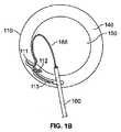
図1A及び1Bを参照すると、3つの亀裂111〜113が、2つの椎体120、130間に位置された椎間板110内部に示される。亀裂を治療するために、椎間板110内部の任意の位置に達するように能動的に操縦することができる伝熱デバイス165は、椎間板110内に挿入され、亀裂を治療するために熱を加えるように作動される。一例において、伝熱デバイスは、例えば亀裂112の一部分を治療するために、椎間板110内部の位置に能動的に操縦される。そして、伝熱デバイスは、亀裂112の別の部分を治療するために(やはり能動操縦を使用して)位置決めし直される。このプロセスが、全ての3つの亀裂が治療されるまで繰り返される。別の例において、伝熱デバイスは、椎間板110内部の位置に能動的に操縦され、例えば亀裂112などの亀裂全体を一度に、または亀裂111及び112及び/または113など複数の亀裂を一度に治療するように熱を供給する。 With reference to FIGS. 1A and 1B, three cracks 111-113 are shown inside the
図1Bで、3つの亀裂111〜113は、椎間板110内で髄核150から環状壁140内に延在して示されている。図示されるように、亀裂111は半径方向裂傷であり、亀裂112及び113は同心円状の裂傷である。 In FIG. 1B, three cracks 111-113 are shown extending from the
伝熱デバイス165は、導入器針160(introducer needle)を通って椎間板内に導入され、デバイス165の遠位部分が亀裂111〜113の任意の1またはそれ以上の近くまたは亀裂の中に誘導されるように能動的に操縦される。例えば、デバイス165は、デバイスの遠位部分が同心円状の裂傷の全長をたどるように能動的に操縦することができる。 The
図1A及び1Bは、椎間板亀裂の三次元性質を示す。デバイスを上下に(図1AでのZ軸に沿って)及び左右に(図1AでのY軸に沿って)能動的に操縦すること、並びにデバイス軸に沿って(図1AでX軸に沿って)デバイスを前進及び後退させることができることが、亀裂に対してデバイスを配置するために所望の自由度をもたらす。Y及びZ軸によって形成される平面内で二次元でデバイスを誘導することができる限り、デバイスは、Y及びZ軸の方向に沿って別個に操縦可能である必要はない。 1A and 1B show the three-dimensional nature of the intervertebral disc crack. Actively steering the device up and down (along the Z axis in FIG. 1A) and left and right (along the Y axis in FIG. 1A), and along the device axis (along the X axis in FIG. 1A) The ability to advance and retract the device provides the desired degree of freedom to position the device relative to the crack. As long as the device can be guided in two dimensions in the plane formed by the Y and Z axes, the device need not be separately steerable along the directions of the Y and Z axes.
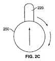
図2A〜2Cを参照すると、伝熱デバイス265は、予備湾曲ガイドワイヤ220の形態での操縦機構を含み、それを介して、伝熱デバイスの加熱部材(図示せず)を前進させることができる。操縦機構は、ガイドワイヤをその長手方向軸の周りで回転させることによってガイドワイヤを能動的に操縦するためのノブまたはダイヤル250を含む。非展開状態(図2A)において、ガイドワイヤ220は、全体が伝熱デバイス265のシース210内部に位置している。 Referring to FIGS. 2A-2C, the
例えばニチノールで形成されるガイドワイヤ220は、所定の湾曲形状を有する。非展開状態において、シース210は、ガイドワイヤをシースの形状で拘束する。図2Bに示されるように、シースからの展開時、ガイドワイヤ220は、その所定の湾曲形状を取る。 For example, the
ガイドワイヤ220は、図2Cに示されるように、ダイヤル250を回転させ、次にそれがガイドワイヤを回転させることによって、Y−Z平面に沿って誘導される。ガイドワイヤの展開前のガイドワイヤ220の回転は、ガイドワイヤがシース210から展開されるときに進む方向を制御する。別法としてまたは追加として、シース210からのガイドワイヤの展開後にガイドワイヤ220を回転させるために、ダイヤル250を使用することができる。ガイドワイヤ220が位置決めされると、加熱部材がガイドワイヤに沿って治療部位に向けて前進される。 The
図3の伝熱デバイス300は、所定の湾曲形状を有するガイドワイヤを採用するのではなく、引張ワイヤ340及び341を使用する能動操縦機構を有する。操縦機構は、シース310内部に配置されたガイドカテーテル320を含む。引張ワイヤ340は、その端部302でガイドカテーテル320の遠位部分304の第1の側に取り付けられる。引張ワイヤ341は、その端部308でガイドカテーテル320の遠位部分304の第2の側に取り付けられており、第2の側は、第1の側から90°の位置にある。両者の引張ワイヤ340及び341も、それらの反対の端部306でハンドル350に取り付けられる。ガイドカテーテル320の遠位部分は、ハンドル350の作動により、引張ワイヤ340が縮められる場合において方向A(すなわち下)に、引張ワイヤ341が縮められる場合において方向B(すなわち一方の側)に湾曲する。いずれの引張ワイヤも縮められないとき、すなわちハンドルが作動しないとき、ガイドカテーテル320は直進方向に進む。ガイドカテーテル320を方向AまたはBと反対の方向に進ませる(すなわち上、または他方の側に進ませる)ために、伝熱デバイスを180°回転させることができる。さらに、ガイドカテーテル320を元の向きから45°または60°などの水平方向に進ませるためには、この結果を実現するように同様に伝熱デバイスを回転させることができる。 The
図3に示されるように、矢印を、ハンドル350などの能動操縦機構の近位端(操作者の把持端部)に示すことができ、能動操縦構成要素が作動するときにデバイスが進む方向を示す。追加としてまたは別法として、矢印を、同様にデバイスまたはガイドカテーテルの近位端に直接示すこともできる。 As shown in FIG. 3, an arrow can be shown at the proximal end (operator's gripping end) of an active steering mechanism, such as
シース310は、例えばプラスチックから形成されており、例えば標準的なルアー接続330を用いてハンドル350に取り付けられる。シース310及び(引張ワイヤ340及び341が取り付けられた状態での)ガイドカテーテル320は、例えば17ゲージ導入器針(図示せず)を使用して椎間板内に挿入される。シース310及びガイドカテーテル320が椎間板内で前進されるとき、ハンドル350を引っ張ることによって能動操縦が実現されて、引張ワイヤ340及び341を縮め、ガイドカテーテル320の先端を曲げ、それによりA及び/またはB方向への撓みを引き起こす。弛緩状態(すなわち、ハンドルが作動されていないとき)において、ガイドカテーテル320及びシース310は、直線方向に前進される。カテーテルが治療部位に適切に配置されると、ルアー接続330を解放することができ、シース310が取り外される。ガイドカテーテル320は、伝熱デバイスの加熱部材など治療デバイスの配置のためのチャネルを形成するために残る。 The
図4において、伝熱デバイス400の能動操縦機構のガイドカテーテル420は、ガイドカテーテル420と同軸に延びるガイドカテーテル420の4つの四分円内に位置された4つの引張ワイヤ441〜444を含む。ワイヤは、例えばワイヤ対441と443、及びワイヤ対442と444など、対として伸縮するように作動及び作動停止される(engaged and disengaged)。4つの引張ワイヤが、二次元での全範囲の移動をもたらす。2つのワイヤ対は、順次または同時に作動させることができる。 In FIG. 4, the
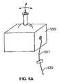
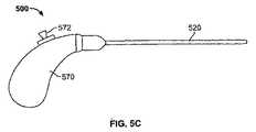
図5Aを参照すると、引張ワイヤは、ケーブル551によってガイドカテーテル420に結合されたジョイスティック550によって制御することができる。ジョイスティック550は、ガイドカテーテル420を能動的に操縦するために、左、右、上、下、及び斜めに動かすことができる。別法として、引張ワイヤは、伝熱デバイス400が接続された発電機560(図5B)にあるジョイスティックまたはボタン562によって制御することができる。図5Cに示されるように、ジョイスティック572は、ガイドカテーテル520を能動的に操縦するために、伝熱デバイス500のハンドル570に一体化することができる。 Referring to FIG. 5A, the pull wire can be controlled by a
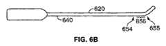
図6A及び6Bを参照すると、引張ワイヤの作動感度は、ガイドカテーテル620に接続される引張ワイヤ640の長さ及び配置を調節することによって制御することができる。例えば、図6Aは、位置651と652との間でのカテーテルの長さ653に沿ってガイドカテーテル620に接続されたワイヤ640を示す。ガイドカテーテルの大部分にわたってワイヤをガイドカテーテルに接続することにより、ワイヤ640が作動される(例えば、縮められる)ときにガイドカテーテル620の大区域が撓む。したがって、ガイドカテーテル620は、ワイヤ640のわずかな縮みに敏感であり、それによって操作者による大量の操縦なしに急に回転する。 With reference to FIGS. 6A and 6B, the actuation sensitivity of the puller wire can be controlled by adjusting the length and placement of the
別の例において、図6Bは、位置654と655との間でのカテーテルのより短い長さ656に沿ってガイドカテーテル620に接続されたワイヤ640を示す。ガイドカテーテルのより小さな部分にわたってワイヤをガイドカテーテルに接続することにより、ワイヤ640が縮められるときに、ガイドカテーテル620のより小区域が撓む。したがって、ガイドカテーテル620の誘導は、図6Aに示される構成と対照的に、小量の操縦に対してそれほど敏感でない。 In another example, FIG. 6B shows a
図7A及び7Bにおいて、ガイドカテーテル720の誘導は、カテーテルを曲げるために伸縮するワイヤではなく、薄いストリップ741〜744によって制御される。ストリップ741〜744は、ガイドカテーテル720の外側(図7A)または内部(図7B)に位置させることができる。ストリップ741〜744は、上述したように例えばハンドル、ダイヤルまたはジョイスティックを使用してガイドカテーテル720を能動的に操縦するように制御することができる。 In FIGS. 7A and 7B, guide
図8A及び8Bを参照すると、ガイドカテーテル820は、ワイヤまたはストリップではなく、ガイドカテーテル820の壁内部に含まれる液体またはゲルなど導電流体に電気を供給することによって制御することができる。図8Aにおいて、ガイドカテーテル820を形成する管は、4つの四分円841〜844を有し、それぞれが導電流体で充填されて部分845によって離隔され、部分845は、いくつかの実装形態において絶縁材料で充填される。図8Bにおいて、ガイドカテーテル820を形成する管は、導電流体840のリングによって取り囲まれる開いたコア845を含む。代替実装形態では、管は、導電流体で完全に充填される。電気が(例えば、ガイドカテーテル820の外壁または内壁に沿って、あるいは流体内に直接的に)流体に加えられるとき、ガイドカテーテルが特定の方向に曲がる。この様式において、操作者は、ある量の電気を印加して、ガイドカテーテルが曲がる量及び方向を能動的に制御し、それによって椎間板内部の所望の位置に向けてガイドカテーテルを能動的に操縦することができる。 Referring to FIGS. 8A and 8B, the
ガイドカテーテルまたはシースを椎間板内に能動的に誘導することは、さまざまな機能が行われるように、椎間板内へのさまざまなデバイスの配置を可能にする。例えば、鋭利なデバイスをシース内に配置することができ、変性された椎間板の核内部で生じるものなど堅い組織を貫通する、または治療のための病理の部位へのアクセスを得るように亀裂の部位における環を貫通する。その後、鋭利なデバイスをシースから取り外すことができ、例えば加熱部材など別のデバイスを挿入することができ、亀裂の除神経を引き起こすために治療部位に熱を加える。別の例では、光ファイバデバイスをシース内部に配置することができ、亀裂の部位を識別する目的または椎間板の変性の状態を検査する目的で、椎間板を視覚化する。さらに、吸引器を含めたオーガ(auger)または他の切除タイプのデバイスをシース内部に配置して、組織を除去するために使用することができる。消化組織への酵素、亀裂を修復するためのシーラント、または椎間板を治療するための製薬剤(1またはそれ以上)などの材料も、シースを通して椎間板内に導入することができる。 Actively guiding the guide catheter or sheath into the intervertebral disc allows various devices to be placed within the intervertebral disc so that various functions can be performed. For example, a sharp device can be placed in the sheath and penetrates hard tissue, such as that occurring within the nucleus of a degenerated disc, or the site of a crack to gain access to a pathological site for treatment Penetrating through the ring. The sharp device can then be removed from the sheath, and another device, such as a heating member, can be inserted, applying heat to the treatment site to cause denervation of the crack. In another example, a fiber optic device can be placed inside the sheath and the disc is visualized for the purpose of identifying the site of the crack or examining the condition of the disc degeneration. In addition, an auger or other ablation type device including an aspirator can be placed inside the sheath and used to remove tissue. Materials such as enzymes to digestive tissue, sealants for repairing cracks, or drugs (one or more) to treat the disc can also be introduced into the disc through the sheath.
椎間板は、しばしば貫通困難なことがある比較的高密度の組織の領域を有するので、能動操縦性による精密な配置に加えて、組織を選択的に貫通することができることが必要となることがある。この高密度組織と接触することが、所望の軌跡からのずれをもたらすことがある。したがって、能動操縦機構は、精密な配置が実現されることを保証するために、高密度組織を貫通するための機能を提供することもある。 Intervertebral discs have areas of relatively dense tissue that are often difficult to penetrate, so in addition to precise placement with active maneuverability, it may be necessary to be able to selectively penetrate tissue . Contact with this dense tissue may result in a deviation from the desired trajectory. Thus, the active steering mechanism may provide a function for penetrating dense tissue to ensure that precise placement is achieved.
シースまたはガイドカテーテルは、17ゲージまたはそれより小さな導入器針に嵌合することが望ましい。椎間板内に設けられた大きな穴が変性をもたらすことが実証されているので、17ゲージ針を使用することは有益である。したがって、シースを通して椎間板内に配置される構成要素及びデバイスのサイズ設定は、制約される可能性がある。しかし、さまざまな機能を有する構成要素の互換性をもたらすことが、それらの構成要素に対するサイズ制約を低減する。上述した構成では、1つの構成要素が、所定時間にシース内部に配置される。したがって、使用すべき各構成要素は、その構成要素が複数の機能を実施するために本体内に一度に挿入される多機能デバイスの部分構成要素にすぎない場合よりも、大きくなることがある。別法として、構成要素は、多機能デバイスの部分構成要素である。 Desirably, the sheath or guide catheter fits into a 17 gauge or smaller introducer needle. The use of a 17 gauge needle is beneficial because large holes provided in the disc have been demonstrated to cause degeneration. Thus, the sizing of components and devices that are placed through the sheath and into the intervertebral disc can be constrained. However, providing compatibility of components having different functions reduces size constraints on those components. In the configuration described above, one component is placed inside the sheath at a predetermined time. Thus, each component to be used may be larger than if the component is only a partial component of a multi-function device that is inserted into the body at one time to perform multiple functions. Alternatively, the component is a partial component of a multifunction device.
椎間板起因の腰痛を治療することに加えて、デバイスの配置が目的の療法を提供するので、根性症状を治療するように意図された椎間板内処置に関する利益も実現することができる。 In addition to treating discogenic low back pain, the benefits of an intradiscal procedure intended to treat radical symptoms can also be realized because the placement of the device provides the targeted therapy.
椎間板内部における伝熱デバイスなどのデバイスの目標配置をもたらすことに加えて、椎間板の実質的な部分または三次元椎間板内部の治療部位に熱を加えるために、大きな加熱プロファイルを形成することができる。それを行うために、大きな体積にわたって大きな加熱プロファイルを形成するように、伝熱デバイスの加熱要素の有効な構成が用いられる。一例において、加熱要素は、カテーテルから展開して広がる一連のワイヤを含む。そして、個々のワイヤは、加熱を誘発するために、単極または双極無線周波数(RF)エネルギー、抵抗性の熱または他のエネルギーを放出できる。そのような展開は、例えば、シースの閉込めを越えて延出される際に所定の形状を取る形状記憶金属を使用することによって達成することができる。また、ばね負荷またはばね付勢構成を使用することもできる。別の例において、加熱要素は、シースの閉込めを越えて延出される際に広がる広い平坦な表面を含む。 In addition to providing a targeted placement of a device, such as a heat transfer device, within the disc, a large heating profile can be created to apply heat to a substantial portion of the disc or a treatment site within the three-dimensional disc. To do that, an effective configuration of the heating elements of the heat transfer device is used to form a large heating profile over a large volume. In one example, the heating element includes a series of wires that unfold from the catheter. Individual wires can then emit monopolar or bipolar radio frequency (RF) energy, resistive heat or other energy to induce heating. Such deployment can be achieved, for example, by using a shape memory metal that takes a predetermined shape as it extends beyond the containment of the sheath. Spring loaded or spring biased configurations can also be used. In another example, the heating element includes a wide flat surface that extends as it extends beyond the containment of the sheath.
椎間板内部のより広い体積に熱を送達するために加熱プロファイルを拡大することは、椎間板の三次元構造ゆえに有用である。椎間板は、X、Y及びZ軸に沿って延在する体積を有する。椎間板は、主として(Z軸に沿った)高さが約0.5から1cmまでの範囲である。伝熱の領域を拡大することによって、例えば治療部位における伝熱デバイスの直接的な位置決めが実現されない場合であっても病理を完全に治療することができることにより、病理の部位での加熱を保証することができる能力が改善される。より詳細には、椎間板の大きな体積にわたって大きな加熱プロファイルを形成することにより、椎間板のz軸に沿った亀裂を含めた亀裂の全てまたは実質的な部分が除神経を引き起こすのに適した熱を受け取る。 Enlarging the heating profile to deliver heat to a larger volume inside the disc is useful because of the three-dimensional structure of the disc. The intervertebral disc has a volume that extends along the X, Y, and Z axes. Intervertebral discs mainly range in height (along the Z axis) from about 0.5 to 1 cm. Enlarging the area of heat transfer ensures that the pathology can be completely treated even if, for example, direct positioning of the heat transfer device at the treatment site is not achieved, thereby ensuring heating at the pathological site The ability to be improved. More specifically, by forming a large heating profile over a large volume of the disc, all or a substantial portion of the crack, including the crack along the z-axis of the disc, receives heat suitable to cause denervation. .
図9A及び9Bを参照すると、伝熱デバイス920は、能動的に操縦可能なシース910と、シース910内部に位置される加熱部材930とを含む。加熱部材930は、亀裂を加熱することによって亀裂を治療するために単極または双極エネルギーを供給するための成形されたワイヤまたは電極の形態で、一連の加熱要素931〜937を含む。 With reference to FIGS. 9A and 9B, the
加熱部材930は、非展開状態(図9A)と展開状態(図9B)との間においてシース910内部で(軸Xに沿って)前進及び後退させることができ、加熱要素931〜937は、展開状態でシース910から延出する。展開状態において、加熱部材930のワイヤが露出されてY及びZ軸に沿って扇状に広がり、それによって加熱部材930の中央から延出するワイヤは、直進またはほぼ直進の形状を含み、中央ワイヤのいずれかの側にあるワイヤは、伝熱デバイス920の中心から離れるように曲げられる。展開時におけるワイヤのそのような広がり及び曲がりは、例えば、シースの閉込めを越えて延出されるときに所定の形状を取る形状記憶金属を使用して達成される。ばね負荷またはばね付勢構成を使用することもできる。ワイヤの遠位先端(各ワイヤの一部分が絶縁される実装形態で)またはワイヤ全体(ワイヤの全体が露出される、または絶縁されない実装形態で)が、展開状態でシース910を越えて延出する。シース910は、上述したように能動的に操縦可能であってよい。別法としてまたは追加として、加熱部材930は、能動的に操縦可能である。シース910は、例えば約0.028インチ(0.7112mm)の内径と約0.036インチ(0.9144mm)の外径とを有する繊維補強ポリイミドの管である。 The
展開状態で扇状に広がるワイヤを含む加熱要素を備えることによって、伝熱デバイス920は、椎間板の大きな体積をカバーするように大きな加熱プロファイルを形成する。大きな加熱プロファイルは、三次元を含む椎間板の体積をカバーし、それによって椎間板または椎間板内部の治療部位のX、Y、及びZ軸に沿って熱を加えることができる。 By providing a heating element that includes a fan-shaped wire in the deployed state, the
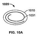
図10A〜10Cを参照すると、伝熱デバイス1020は、シース1010と、加熱部材1030とを含む。加熱部材1030は、椎間板の大きな体積をカバーするために、展開状態(図10B及び10C)で、拡大された平坦なプロフィルを有する加熱要素1031を含む。非展開状態(図10A)において、加熱要素1031は、シース1010内部で完全に巻かれる。他の実装形態において、加熱要素1031は、展開及び非展開状態で他の形状を取ることができる。シース及び/または加熱部材は、能動的に操縦可能であってよい。 Referring to FIGS. 10A to 10C, the
図11A及び11Bを参照すると、図9A及び9Bに示されるものなど伝熱デバイス1120は、双極構成で正及び負の電圧で交互に帯電された加熱要素電極1131〜1136を含む。例えば、電極1131、1133、及び1135は負に帯電され、電極1132、1134、及び1136は正に帯電される。他の実装形態において、電極は単極様式で構成され、それによって電極は全て正に帯電され、接地パッドが患者の皮膚に配置される。 Referring to FIGS. 11A and 11B, a
図12を参照すると、伝熱デバイス1220の加熱部材1230は、シース1210から外に延出する一連の加熱ワイヤ1231〜1234を含む。ワイヤ1231〜1234は、バスケット構成を成す。いくつかの実装形態において、バスケットは、時計方向、半時計方向またはその両方に回転する。いくつかの実装形態において、回転は、回転機構に電力を印加するオン/オフスイッチを作動することによって開始することができ、それによって選択された方向でバスケットを回転させる。別法として、手動クランクまたはダイヤルが、選択された方向で回転され、選択された方向でバスケットを回転させる。バスケットを回転させることが、加熱部材1230によってもたらされる加熱プロファイルを拡大する。 Referring to FIG. 12, the
ワイヤは、双極構成では正及び負の電圧で交互に帯電され、バスケット内部及び周囲に集中加熱領域を生成する。別法として、単極構成が使用され、全てのワイヤ1231〜1234が正に帯電され、熱は、ワイヤから患者の皮膚に配置された接地パッドの位置に流れる。 The wires are alternately charged with positive and negative voltages in a bipolar configuration, creating a concentrated heating area in and around the basket. Alternatively, a unipolar configuration is used, all
図13では、伝熱デバイス1320の双極電極1331〜1334は、例えば薄いポリエステル収縮配管(polyester shrink tubing)1332a及び1334aを用いて部分的に絶縁され(電極1332及び1334)て正の電極を形成して高い電圧を供給し、または裸すなわち絶縁されずに(電極1331及び1333)接地帰路(ground-return)を形成する。 In FIG. 13, the
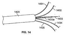
図14において、伝熱デバイス1420は、5つのワイヤ電極1431〜1435を含む。中心プロング(prong)1433は、直進形状を有し、遠位先端から例えば0.2インチ(5.08mm)の位置まで絶縁体1433aで絶縁されている。4つのサイドプロング1431、1432、1434及び1435は絶縁されない。加熱部材1430は双極様式で構成されており、プロング1433は高い電圧を供給し、プロング1431、1432、1434、及び1435は接地帰路として使用される。双極構成では、電流密度が非絶縁部分において比較的高いので、中心プロング1433の非絶縁部分の小さな表面積が変性のサイズを制限する。 In FIG. 14, the
図15を参照すると、伝熱デバイス1520が、いずれも少なくとも部分的に絶縁された双極電極ワイヤ1531〜1534を含む。ワイヤ1531〜1534それぞれは、1531a〜1534aで示されるように、遠位先端での露出部分まで絶縁されている。プロングの遠位先端での露出部分は、例えば長さ0.2インチ(5.08mm)である。そのような絶縁により、複数の正及び負に帯電された(または接地された)電極それぞれの先端に表面積が形成される。この構成は、全ての4つのプロング1531〜1534の先端での高い電流密度により、より大きな直径を有する変性領域が生成されるようにする。絶縁されない先端のサイズを増加することによって、生成される変性のサイズが制御される。しかし、より大きな電気的表面積は、変性を引き起こすために適切な加熱を実現するためにより多くの電力を必要とする。 Referring to FIG. 15, a
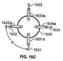
図16A〜16Cでは、伝熱デバイス1620は、絶縁部分1631a〜1634aを有するワイヤ電極プロング1631〜1634を含む。プロング1631〜1634は、扇状に広げられた形状ではなく、直進形状を有し、互いに平行になるように構成される。したがって、プロング1631〜1634それぞれの間の距離Aは、プロング間の距離がプロングの長さに沿って変化する様式で展開するのではなく、展開状態で非絶縁部分に沿って一定のままである。この様式において、(双極構成で)プロング間を流れる、または(単極構成で)プロングから流れる電流は、電気経路がより一定のままであるので、より均一に分散される。絶縁部分1631a〜1634aは、プロング1631〜1634それぞれの非平行部分を覆う。上述したように、加熱部材を形成するプロングまたは電極の構成は、形成される加熱プロファイルひいては治療の効力(例えば、変性の位置及び密度)に影響を及ぼす。例えば、プロングの非絶縁部分のサイズ(すなわち、各プロングにおける絶縁量)を調節することによって、変性サイズ及び位置を制御することができる。また、印加するエネルギーが多くなるにしたがってより多くの変性が生成されるため、送達されるエネルギーの量は、変性の生成に影響を及ぼしてそれを制御する。また、時間/温度効果が存在し、一般に、加熱時間が長くなるにしたがって組織効果を向上させてより多くの変性を生成する。また、プロングの直径を変えることが、変性形状及び分布に影響を及ぼす。 In FIGS. 16A-16C, the
図17及び18を参照すると、導電材料などの流体を、伝熱及び除神経の補助となるように治療部位内に注入することができる。いくつかの実装形態において、上述したさまざまな加熱要素構成を採用することに加えて、またはその代わりに、導電材料を使用することによってより大きな加熱プロファイルが形成される。治療すべき組織が高いインピーダンスを有する場合、組織が低いインピーダンスを有する場合よりも少量の伝熱(より小さな変性サイズをもたらす)が要求される。一実施形態において、治療部位での組織のインピーダンスは、例えば食塩水などの導電材料を注入することによって一時的に減少させることができる。インピーダンスを一時的に減少することにより、導電材料は、治療部位での導電率を一時的に高めることができる。次いで、熱またはエネルギーが、導電材料が導入されている組織に加えられて、導電材料の注入なしで得られたよりも比較的大きな変性を生成する。 Referring to FIGS. 17 and 18, a fluid, such as a conductive material, can be injected into the treatment site to aid in heat transfer and denervation. In some implementations, a larger heating profile is formed by using conductive materials in addition to or instead of employing the various heating element configurations described above. If the tissue to be treated has a high impedance, a smaller amount of heat transfer (resulting in a smaller denatured size) is required than if the tissue has a low impedance. In one embodiment, the tissue impedance at the treatment site can be temporarily reduced by injecting a conductive material, such as saline. By temporarily reducing the impedance, the conductive material can temporarily increase the conductivity at the treatment site. Heat or energy is then applied to the tissue into which the conductive material has been introduced, producing a relatively greater denaturation than that obtained without injection of the conductive material.
図17において、導入器針1760は椎間板内に挿入されており、例えば伝熱及び導電材料供給デバイス1765などのデバイスが治療部位まで誘導されている。治療部位は、亀裂1770の部位である。導電材料1780が、デバイス1765を通して亀裂1770内に導入される。 In FIG. 17, an
導電材料1780は、例えば食塩水であってもよい。食塩水は、椎間板内部の所望の位置(すなわち治療部位)に供給されており、他の無関係の位置に供給されないことが好ましい。所望の位置への食塩水の導入を制限するために、例えば増粘された(thickened)電解媒体など、代替または追加の材料を使用することができる。増粘された電解媒体は、亀裂内部で型を形成するために治療部位で「セットアップ(set up)」することができる。他の実装形態において、導電材料1780は、放射線不透過性色素である。放射線不透過性色素は、蛍光透視視覚化をもたらすまたは色素の導入に続いて椎間板内に配置される光ファイバによる視覚的位置特定を補助するために使用することができる。導電材料1780が亀裂1770内に導入されると、伝熱デバイスを使用して導電材料に熱を加え、それにより亀裂を加熱することができる。 The
一実施形態において、亀裂は、それが漏出性であるか否か判定するために椎間板造影法を使用して分析される。この判定は、導電材料を導入するか否か決定する際の重要な第1の段階である。亀裂が漏出性である場合、亀裂内に導入される導電材料は、椎間板から流出することがあり、所望レベルのインピーダンス減少及び導電率増加がもたらされない。 In one embodiment, the crack is analyzed using discography to determine if it is leaky. This determination is an important first step in determining whether to introduce a conductive material. If the crack is leaky, the conductive material introduced into the crack may flow out of the intervertebral disc and will not result in the desired level of impedance reduction and conductivity increase.
治療部位を適切に加熱するために、大きな体積にわたって45℃よりも高い温度が、治療部位のほぼ全体に加えられる。追加としてまたは別法として、45℃よりも高い温度が、より小さな体積にわたって達成される。伝熱デバイスによってもたらされる熱の温度の制御は、熱電対(TC)または同様のセンサを使用する温度の測定に基づく。TC読取値に基づいて、発電機電力は、適当量の熱を供給するように調整することができる。 In order to properly heat the treatment site, a temperature higher than 45 ° C. over a large volume is applied to almost the entire treatment site. Additionally or alternatively, temperatures above 45 ° C. are achieved over a smaller volume. Control of the temperature of the heat provided by the heat transfer device is based on measuring the temperature using a thermocouple (TC) or similar sensor. Based on the TC reading, the generator power can be adjusted to provide an appropriate amount of heat.
図17を参照すると、熱電対(TC)1790が、亀裂1770内部の導電材料1780に加えられる熱の温度を測定するために、環1750の外側に配置される。TC1790を使用して、導電材料1780に加えられる熱の温度及び量を監視し、したがってその温度及び量の制御及び変更を決定する。一実装形態において、図17に示されるように、TCは、例えば蛍光透視誘導の下で位置決めされる導入器針を使用して、病理の部位(例えば、亀裂の部位での外側環)に直接配置される。亀裂は、例えば磁気共鳴映像法(MRI)または椎間板造影技法を使用して位置特定される。伝熱デバイスは、椎間板内に配置されており、内側環にある亀裂の部位に向けて能動的に操縦され、外部TCでの十分な温度読取値が達成されるまで熱を加えるために使用される。この手法において、温度制御は、部位及び/または患者に特有のものであってよい。したがって、除神経を実現するのに適切な温度が供給されるが、この技法は、熱療法を受けるように意図されていない構造に対する損傷を制限するので、より安全である。 Referring to FIG. 17, a thermocouple (TC) 1790 is placed outside
別の実装形態において、伝熱デバイスは、伝熱デバイスに取り付けられた一体型TCを含む。TCは、伝熱デバイスの加熱部材での温度ではなく、治療される部位での温度を測定するようにデバイス上に配置することができる。これは、伝熱デバイスの加熱部材が治療部位から選択された距離隔てて配置されているときに有用である。したがって、TCは、伝熱デバイスの加熱部材から選択された距離隔ててデバイス上に配置することができ、選択された距離は、加熱部材から治療部位までの距離と同じ、加熱部材からの距離である。例えば、TCは、加熱部材からある距離(すなわち、加熱部材から治療部位までの距離と同じ距離)での温度を測定することができるように、伝熱デバイスの長さに沿って近位または遠位にある距離に配置される。この手法は、適切な熱が所望の位置に供給されることを保証する助けとなる。さらに別の実装形態では、伝熱デバイスと一体でないTCを、伝熱デバイスの操縦とは別の誘導によって、治療部位にまたは治療部位から選択された距離隔てて配置することができる。 In another implementation, the heat transfer device includes an integrated TC attached to the heat transfer device. The TC can be placed on the device to measure the temperature at the site to be treated rather than the temperature at the heating member of the heat transfer device. This is useful when the heating member of the heat transfer device is placed at a selected distance from the treatment site. Thus, the TC can be placed on the device at a selected distance from the heating member of the heat transfer device, and the selected distance is the same distance from the heating member as the distance from the heating member to the treatment site. is there. For example, the TC can be proximal or far along the length of the heat transfer device so that it can measure temperature at a distance from the heating member (ie, the same distance from the heating member to the treatment site). Placed at a certain distance. This approach helps to ensure that adequate heat is delivered to the desired location. In yet another implementation, a TC that is not integral with the heat transfer device can be placed at or at a selected distance from the treatment site by guidance other than steering the heat transfer device.
図18を参照すると、例えば食塩水などの導電材料を椎間板内に注入するために、ワイヤ電極1831〜1834を含むデバイス1820の中央ポスト1840を使用することができる。中央ポスト1840は、内部ボア1841を含み、遠位先端以外は、参照番号1843で示されるように絶縁される。遠位先端は、参照番号1842で示されるように穿孔され、治療部位(例えば、変性が望まれる位置)での組織全体にわたる、内部ボアを通してもたらされる導電材料の拡散を可能にするように構成される。また、中央ポスト1840は、通電することもでき、他のプロング1831〜1834は、接地帰路として働く。 Referring to FIG. 18, the
椎間板内部の治療部位に熱及び/または導電材料を加えるためのデバイスは、頑丈であり、剛性があり、高い曲げ率を有する。これらの属性は、デバイスが、椎間板の環状壁及び椎間板内部の組織に特有である高密度組織を通して誘導されることを可能にする。さらに、デバイスは、デバイスが誘導される椎間板内の領域及び椎間板の体積に相応するようなサイズで構成することができる。 Devices for applying heat and / or conductive material to a treatment site within an intervertebral disc are robust, rigid and have a high bending rate. These attributes allow the device to be guided through high density tissue that is characteristic of the annular wall of the disc and the tissue within the disc. Further, the device can be sized to correspond to the area within the disc from which the device is guided and the volume of the disc.
いくつかの実装形態において、伝熱デバイスは、例えば460kHzの周波数を有するRFエネルギーを加えるように構成される。他の実装形態は、例えば1MHzなど、より高い周波数を提供するように構成される。 In some implementations, the heat transfer device is configured to apply RF energy having a frequency of, for example, 460 kHz. Other implementations are configured to provide higher frequencies, eg, 1 MHz.
この開示は、椎間板起因の痛みの治療に主に焦点を当てられているが、開示した技法を使用して神経根痛を治療することもできる。例えば、椎間板ヘルニア組織を除去し、収縮させて、それにより生じる神経根での発作(例えば圧迫及び感作)を減少し、根性症状を効果的に緩和することができる。 Although this disclosure is primarily focused on the treatment of disc-induced pain, the disclosed techniques can also be used to treat nerve root pain. For example, disc herniated tissue can be removed and contracted to reduce the resulting nerve root attacks (eg, compression and sensitization) and effectively relieve radical symptoms.
いくつかの実施形態を説明してきた。それにも関わらず、さまざまな変更を施すことができることを理解されよう。例えば、さまざまな実装形態の要素を組み合わせ、補い、または取り除いて、他の実装形態を生成することができる。特に、大きな加熱プロファイルを形成する実装形態からの特徴を、能動操縦機構を使用してデバイスの照準された配置を提供する実装形態からの特徴と組み合わせることができる。したがって、これら及びその他の特徴は、頭記の特許請求の範囲内にある。 Several embodiments have been described. Nevertheless, it will be understood that various changes can be made. For example, elements of various implementations can be combined, supplemented, or removed to generate other implementations. In particular, features from an implementation that forms a large heating profile can be combined with features from an implementation that uses an active steering mechanism to provide an aimed placement of the device. Accordingly, these and other features are within the scope of the appended claims.
110 椎間板
111,112,113,1770 亀裂
120,130 椎体
140 環状壁
150 髄核
160,1760 導入器針
165,265,300,400,500,920,1020,1120,1220,1320,1420,1520,1620,1820 伝熱デバイス(デバイス)
210,310,910,1210 シース
220 ガイドワイヤ(予備湾曲ガイドワイヤ)
250,350 ノブ(ダイヤル,ハンドル)
320,420,520,620,720,820 ガイドカテーテル
340,341,411〜444 引張ワイヤ
550,572 ジョイスティック
741〜744 ストリップ
840 導電流体
930,1030,1230,1430 加熱部材
1131〜1136 加熱要素電極
1790 熱電対(TC)110 Intervertebral disc 111,112,113,1770 Crack 120,130
210, 310, 910, 1210
250, 350 knob (dial, handle)
320, 420, 520, 620, 720, 820
Claims (33)
Translated fromJapanese少なくとも二次元において前記伝熱デバイスの誘導可能に構成された能動操縦機構と、
を備える椎間板治療デバイス。A heat transfer device configured to surround a three-dimensional volume of the intervertebral disc to provide heat to a three-dimensional treatment site within the intervertebral disc;
An active steering mechanism configured to be steerable of the heat transfer device in at least two dimensions;
An intervertebral disc treatment device comprising:
ガイドカテーテルと、
前記ガイドカテーテルを曲げるための前記ガイドカテーテルに取り付けられた引張要素と、
を備える請求項1に記載のデバイス。The active steering mechanism is
A guide catheter;
A tension element attached to the guide catheter for bending the guide catheter;
The device of claim 1 comprising:
ガイドカテーテルと、
前記ガイドカテーテル内部に収容される導電流体であって、前記ガイドカテーテルを曲げるために電気を加えることができる導電流体と、
を備える請求項1に記載のデバイス。The active steering mechanism is
A guide catheter;
A conductive fluid contained within the guide catheter, the conductive fluid capable of applying electricity to bend the guide catheter;
The device of claim 1 comprising:
シースと、
非展開状態で前記シース内部で巻かれている電極を含む加熱部材と、
を備える請求項1に記載のデバイス。The heat transfer device is
A sheath,
A heating member including an electrode wound inside the sheath in a non-deployed state;
The device of claim 1 comprising:
前記椎間板内部の治療部位の領域に向けて伝熱デバイスを能動的に操縦する段階であって、前記治療部位が三次元であり、前記操縦が、少なくとも二次元で前記伝熱デバイスを誘導する段階と、
前記伝熱デバイスを使用して、前記治療部位の前記領域に熱を加える段階と、
を含む方法。A method for treating an intervertebral disc, comprising:
Actively maneuvering a heat transfer device toward a region of a treatment site within the intervertebral disc, wherein the treatment site is three-dimensional and the maneuvering guides the heat transfer device in at least two dimensions When,
Applying heat to the region of the treatment site using the heat transfer device;
Including methods.
前記伝熱デバイスを能動的に操縦する段階が、
前記椎間板内部の前記治療部位の前記領域に向けてガイドワイヤを能動的に操縦する段階と、
前記ガイドワイヤを介して前記治療部位の前記領域に向けて前記加熱要素を前進させる段階と、
を含む請求項9に記載の方法。The heat transfer device comprises a guide wire and a heating element;
Actively steering the heat transfer device comprises:
Actively maneuvering a guidewire toward the region of the treatment site within the intervertebral disc;
Advancing the heating element through the guidewire toward the region of the treatment site;
The method of claim 9 comprising:
前記伝熱デバイスを能動的に操縦する段階が、
前記椎間板内部の前記治療部位の前記領域に向けて前記シースを能動的に操縦する段階と、
前記シースを通して前記治療部位の前記領域に向けて前記加熱要素を前進させる段階と
を含む請求項9に記載の方法。The heat transfer device comprises a sheath and a heating element;
Actively steering the heat transfer device comprises:
Actively maneuvering the sheath toward the region of the treatment site within the intervertebral disc;
10. The method of claim 9, comprising advancing the heating element through the sheath toward the region of the treatment site.
前記シースから前記加熱要素を取り外す段階と、
前記シースを通して、前記治療部位に向けて、伝熱以外の働きを有する第2のデバイスを前進させる段階と、
を含む請求項13に記載の方法。further,
Removing the heating element from the sheath;
Advancing a second device having a function other than heat transfer through the sheath toward the treatment site;
The method of claim 13 comprising:
前記治療部位内に導電材料を注入する段階と、
前記治療部位内の前記導電材料に熱を加える段階と、
を含む請求項9に記載の方法。further,
Injecting a conductive material into the treatment site;
Applying heat to the conductive material in the treatment site;
The method of claim 9 comprising:
前記治療部位に熱を加える段階が、前記椎間板の前記環の内壁に熱を加える段階を含む請求項20に記載の方法。Further comprising placing a thermocouple on the outer wall of the disc annulus to monitor the temperature of the heat applied to the treatment site;
21. The method of claim 20, wherein applying heat to the treatment site includes applying heat to an inner wall of the annulus of the intervertebral disc.
さらに、前記治療部位に加えられる前記熱の温度を監視するために前記伝熱デバイスから前記治療部位までの距離に相当する前記伝熱デバイスからの距離に熱電対を配置する段階を含む請求項20に記載の方法。Actively steering the heat transfer device toward the region of the treatment site includes actively steering the heat transfer device toward a distance from the treatment site;
21. The method further comprises disposing a thermocouple at a distance from the heat transfer device corresponding to a distance from the heat transfer device to the treatment site to monitor the temperature of the heat applied to the treatment site. The method described in 1.
前記電極間の距離が、前記電極の長さに沿って一定である請求項25に記載の方法。Applying heat to the treatment site using the heating element comprises applying heat to the treatment site using at least two electrodes;
26. The method of claim 25, wherein the distance between the electrodes is constant along the length of the electrodes.
前記加熱要素が、前記治療部位内に前記流体を注入するように構成される請求項25に記載の方法。And injecting fluid into the treatment site,
26. The method of claim 25, wherein the heating element is configured to inject the fluid into the treatment site.
Applications Claiming Priority (2)
| Application Number | Priority Date | Filing Date | Title |
|---|---|---|---|
| US68451805P | 2005-05-26 | 2005-05-26 | |
| PCT/US2006/020379WO2006127970A2 (en) | 2005-05-26 | 2006-05-26 | Electrothermal intervertebral disc treatment |
Publications (1)
| Publication Number | Publication Date |
|---|---|
| JP2008541878Atrue JP2008541878A (en) | 2008-11-27 |
Family
ID=37307146
Family Applications (1)
| Application Number | Title | Priority Date | Filing Date |
|---|---|---|---|
| JP2008513747APendingJP2008541878A (en) | 2005-05-26 | 2006-05-26 | Electrothermal disc treatment |
Country Status (6)
| Country | Link |
|---|---|
| US (1) | US20070016273A1 (en) |
| EP (1) | EP1922006A2 (en) |
| JP (1) | JP2008541878A (en) |
| AU (1) | AU2006249799A1 (en) |
| CA (1) | CA2609591A1 (en) |
| WO (1) | WO2006127970A2 (en) |
Cited By (10)
| Publication number | Priority date | Publication date | Assignee | Title |
|---|---|---|---|---|
| JP2015512712A (en)* | 2012-03-27 | 2015-04-30 | ディファイン, インコーポレイテッド | Method and system for use in controlling tissue ablation volume by temperature monitoring |
| US10463380B2 (en) | 2016-12-09 | 2019-11-05 | Dfine, Inc. | Medical devices for treating hard tissues and related methods |
| US10478241B2 (en) | 2016-10-27 | 2019-11-19 | Merit Medical Systems, Inc. | Articulating osteotome with cement delivery channel |
| US10624652B2 (en) | 2010-04-29 | 2020-04-21 | Dfine, Inc. | System for use in treatment of vertebral fractures |
| US10660656B2 (en) | 2017-01-06 | 2020-05-26 | Dfine, Inc. | Osteotome with a distal portion for simultaneous advancement and articulation |
| US11026744B2 (en) | 2016-11-28 | 2021-06-08 | Dfine, Inc. | Tumor ablation devices and related methods |
| JP2021180885A (en)* | 2016-05-31 | 2021-11-25 | クレオ・メディカル・リミテッドCreo Medical Limited | Electrosurgical apparatus and method |
| US11197681B2 (en) | 2009-05-20 | 2021-12-14 | Merit Medical Systems, Inc. | Steerable curvable vertebroplasty drill |
| US11510723B2 (en) | 2018-11-08 | 2022-11-29 | Dfine, Inc. | Tumor ablation device and related systems and methods |
| US11986229B2 (en) | 2019-09-18 | 2024-05-21 | Merit Medical Systems, Inc. | Osteotome with inflatable portion and multiwire articulation |
Families Citing this family (12)
| Publication number | Priority date | Publication date | Assignee | Title |
|---|---|---|---|---|
| US20080228135A1 (en)* | 2007-03-05 | 2008-09-18 | Elizabeth Ann Snoderly | Apparatus for treating a damaged spinal disc |
| EP2008600B1 (en)* | 2007-06-25 | 2010-09-22 | Terumo Kabushiki Kaisha | Medical device |
| US8394090B2 (en)* | 2007-06-25 | 2013-03-12 | Terumo Kabushiki Kaisha | Medical device |
| US8470043B2 (en)* | 2008-12-23 | 2013-06-25 | Benvenue Medical, Inc. | Tissue removal tools and methods of use |
| US9161773B2 (en) | 2008-12-23 | 2015-10-20 | Benvenue Medical, Inc. | Tissue removal tools and methods of use |
| US9480574B2 (en) | 2013-03-14 | 2016-11-01 | Benvenue Medical, Inc. | Spinal fusion implants and devices and methods for deploying such implants |
| US10314605B2 (en) | 2014-07-08 | 2019-06-11 | Benvenue Medical, Inc. | Apparatus and methods for disrupting intervertebral disc tissue |
| US10022243B2 (en) | 2015-02-06 | 2018-07-17 | Benvenue Medical, Inc. | Graft material injector system and method |
| US20170143405A1 (en)* | 2015-11-20 | 2017-05-25 | Covidien Lp | Apparatuses, systems and methods for treating ulcerative colitis and other inflammatory bowel diseases |
| US10758286B2 (en) | 2017-03-22 | 2020-09-01 | Benvenue Medical, Inc. | Minimal impact access system to disc space |
| WO2019148083A1 (en) | 2018-01-29 | 2019-08-01 | Benvenue Medical, Inc. | Minimally invasive interbody fusion |
| WO2019178575A1 (en) | 2018-03-16 | 2019-09-19 | Benvenue Medical, Inc. | Articulated instrumentation and methods of using the same |
Family Cites Families (17)
| Publication number | Priority date | Publication date | Assignee | Title |
|---|---|---|---|---|
| JP2782728B2 (en)* | 1988-09-06 | 1998-08-06 | セイコーエプソン株式会社 | Printer paper feeder |
| US5104393A (en)* | 1989-08-30 | 1992-04-14 | Angelase, Inc. | Catheter |
| US5125896A (en)* | 1990-10-10 | 1992-06-30 | C. R. Bard, Inc. | Steerable electrode catheter |
| AU660444B2 (en)* | 1991-02-15 | 1995-06-29 | Ingemar H. Lundquist | Torquable catheter and method |
| US5431649A (en)* | 1993-08-27 | 1995-07-11 | Medtronic, Inc. | Method and apparatus for R-F ablation |
| US5462545A (en)* | 1994-01-31 | 1995-10-31 | New England Medical Center Hospitals, Inc. | Catheter electrodes |
| NZ272354A (en)* | 1994-06-17 | 1997-10-24 | Trudell Medical Ltd | Catheter system; method and apparatus for delivering an aerosol form of medication to the lungs, details of method and of catheter apparatus |
| US5868740A (en)* | 1995-03-24 | 1999-02-09 | Board Of Regents-Univ Of Nebraska | Method for volumetric tissue ablation |
| US6159208A (en)* | 1995-06-07 | 2000-12-12 | Arthocare Corporation | System and methods for electrosurgical treatment of obstructive sleep disorders |
| US5638564A (en)* | 1995-11-02 | 1997-06-17 | Foot Levelers, Inc. | Therapeutic pillow |
| US5755760A (en)* | 1996-03-11 | 1998-05-26 | Medtronic, Inc. | Deflectable catheter |
| US7069087B2 (en)* | 2000-02-25 | 2006-06-27 | Oratec Interventions, Inc. | Apparatus and method for accessing and performing a function within an intervertebral disc |
| US6055457A (en)* | 1998-03-13 | 2000-04-25 | Medtronic, Inc. | Single pass A-V lead with active fixation device |
| EP1063931A2 (en)* | 1998-03-19 | 2001-01-03 | Oratec Interventions, Inc. | Catheter for delivery of energy to a surgical site |
| US6889089B2 (en)* | 1998-07-28 | 2005-05-03 | Scimed Life Systems, Inc. | Apparatus and method for treating tumors near the surface of an organ |
| US6562033B2 (en)* | 2001-04-09 | 2003-05-13 | Baylis Medical Co. | Intradiscal lesioning apparatus |
| US6638276B2 (en)* | 2001-06-06 | 2003-10-28 | Oratec Interventions, Inc. | Intervertebral disc device employing prebent sheath |
- 2006
- 2006-05-26USUS11/420,673patent/US20070016273A1/ennot_activeAbandoned
- 2006-05-26JPJP2008513747Apatent/JP2008541878A/enactivePending
- 2006-05-26CACA002609591Apatent/CA2609591A1/ennot_activeAbandoned
- 2006-05-26AUAU2006249799Apatent/AU2006249799A1/ennot_activeAbandoned
- 2006-05-26EPEP06771260Apatent/EP1922006A2/ennot_activeWithdrawn
- 2006-05-26WOPCT/US2006/020379patent/WO2006127970A2/enactiveApplication Filing
Cited By (21)
| Publication number | Priority date | Publication date | Assignee | Title |
|---|---|---|---|---|
| US11197681B2 (en) | 2009-05-20 | 2021-12-14 | Merit Medical Systems, Inc. | Steerable curvable vertebroplasty drill |
| US10624652B2 (en) | 2010-04-29 | 2020-04-21 | Dfine, Inc. | System for use in treatment of vertebral fractures |
| JP2015512712A (en)* | 2012-03-27 | 2015-04-30 | ディファイン, インコーポレイテッド | Method and system for use in controlling tissue ablation volume by temperature monitoring |
| US10028784B2 (en) | 2012-03-27 | 2018-07-24 | Dfine, Inc. | Methods and systems for use in controlling tissue ablation volume by temperature monitoring |
| US12064176B2 (en) | 2016-05-31 | 2024-08-20 | Creo Medical Limited | Electrosurgical apparatus and method |
| JP2021180885A (en)* | 2016-05-31 | 2021-11-25 | クレオ・メディカル・リミテッドCreo Medical Limited | Electrosurgical apparatus and method |
| US11564741B2 (en) | 2016-05-31 | 2023-01-31 | Creo Medical Limited | Electrosurgical apparatus and method |
| US11344350B2 (en) | 2016-10-27 | 2022-05-31 | Dfine, Inc. | Articulating osteotome with cement delivery channel and method of use |
| US10478241B2 (en) | 2016-10-27 | 2019-11-19 | Merit Medical Systems, Inc. | Articulating osteotome with cement delivery channel |
| US12433671B2 (en) | 2016-11-28 | 2025-10-07 | Dfine, Inc. | Tumor ablation devices and related methods |
| US11026744B2 (en) | 2016-11-28 | 2021-06-08 | Dfine, Inc. | Tumor ablation devices and related methods |
| US11116570B2 (en) | 2016-11-28 | 2021-09-14 | Dfine, Inc. | Tumor ablation devices and related methods |
| US12011215B2 (en) | 2016-11-28 | 2024-06-18 | Dfine, Inc. | Tumor ablation devices and related methods |
| US10463380B2 (en) | 2016-12-09 | 2019-11-05 | Dfine, Inc. | Medical devices for treating hard tissues and related methods |
| US11540842B2 (en) | 2016-12-09 | 2023-01-03 | Dfine, Inc. | Medical devices for treating hard tissues and related methods |
| US10470781B2 (en) | 2016-12-09 | 2019-11-12 | Dfine, Inc. | Medical devices for treating hard tissues and related methods |
| US11607230B2 (en) | 2017-01-06 | 2023-03-21 | Dfine, Inc. | Osteotome with a distal portion for simultaneous advancement and articulation |
| US10660656B2 (en) | 2017-01-06 | 2020-05-26 | Dfine, Inc. | Osteotome with a distal portion for simultaneous advancement and articulation |
| US11510723B2 (en) | 2018-11-08 | 2022-11-29 | Dfine, Inc. | Tumor ablation device and related systems and methods |
| US11937864B2 (en) | 2018-11-08 | 2024-03-26 | Dfine, Inc. | Ablation systems with parameter-based modulation and related devices and methods |
| US11986229B2 (en) | 2019-09-18 | 2024-05-21 | Merit Medical Systems, Inc. | Osteotome with inflatable portion and multiwire articulation |
Also Published As
| Publication number | Publication date |
|---|---|
| US20070016273A1 (en) | 2007-01-18 |
| CA2609591A1 (en) | 2006-11-30 |
| WO2006127970A3 (en) | 2007-01-18 |
| AU2006249799A1 (en) | 2006-11-30 |
| EP1922006A2 (en) | 2008-05-21 |
| WO2006127970A2 (en) | 2006-11-30 |
Similar Documents
| Publication | Publication Date | Title |
|---|---|---|
| JP2008541878A (en) | Electrothermal disc treatment | |
| AU2023204019B2 (en) | Systems and methods for creating curved paths through bone and modulating nerves within the bone | |
| US6767347B2 (en) | Catheter for delivery of energy to a surgical site | |
| AU2013337680A1 (en) | Systems and methods for creating curved paths through bone and modulating nerves within the bone | |
| HK1212186B (en) | Systems for creating curved paths through bone and modulating nerves within the bone |