JP2008541614A - Vehicle network and method with time slot access - Google Patents
Vehicle network and method with time slot accessDownload PDFInfo
- Publication number
- JP2008541614A JP2008541614AJP2008511144AJP2008511144AJP2008541614AJP 2008541614 AJP2008541614 AJP 2008541614AJP 2008511144 AJP2008511144 AJP 2008511144AJP 2008511144 AJP2008511144 AJP 2008511144AJP 2008541614 AJP2008541614 AJP 2008541614A
- Authority
- JP
- Japan
- Prior art keywords
- link
- network
- time slot
- resource
- communication link
- Prior art date
- Legal status (The legal status is an assumption and is not a legal conclusion. Google has not performed a legal analysis and makes no representation as to the accuracy of the status listed.)
- Pending
Links
- 238000000034methodMethods0.000titleclaimsabstractdescription37
- 238000004891communicationMethods0.000claimsabstractdescription122
- 238000013507mappingMethods0.000claimsabstractdescription21
- 230000001960triggered effectEffects0.000claimsdescription19
- 230000003068static effectEffects0.000claimsdescription5
- 230000005540biological transmissionEffects0.000claimsdescription4
- 230000008569processEffects0.000description13
- 230000006870functionEffects0.000description10
- 238000010586diagramMethods0.000description8
- 239000004744fabricSubstances0.000description8
- 239000006163transport mediaSubstances0.000description6
- 238000013468resource allocationMethods0.000description4
- 238000001514detection methodMethods0.000description3
- 238000012546transferMethods0.000description3
- 230000002457bidirectional effectEffects0.000description2
- 230000004397blinkingEffects0.000description2
- 238000005516engineering processMethods0.000description2
- 239000002609mediumSubstances0.000description2
- 230000002093peripheral effectEffects0.000description2
- 238000012545processingMethods0.000description2
- 238000012384transportation and deliveryMethods0.000description2
- 241001417501LobotidaeSpecies0.000description1
- 230000003044adaptive effectEffects0.000description1
- 230000008901benefitEffects0.000description1
- 230000008859changeEffects0.000description1
- 230000008878couplingEffects0.000description1
- 238000010168coupling processMethods0.000description1
- 238000005859coupling reactionMethods0.000description1
- 125000004122cyclic groupChemical group0.000description1
- 230000007547defectEffects0.000description1
- 230000001934delayEffects0.000description1
- 238000011161developmentMethods0.000description1
- 238000007726management methodMethods0.000description1
- 230000007246mechanismEffects0.000description1
- 238000012544monitoring processMethods0.000description1
- 230000003287optical effectEffects0.000description1
- 239000013307optical fiberSubstances0.000description1
- 230000002085persistent effectEffects0.000description1
- 230000000717retained effectEffects0.000description1
- 230000002441reversible effectEffects0.000description1
- 230000011664signalingEffects0.000description1
- 239000000725suspensionSubstances0.000description1
- 238000013519translationMethods0.000description1
- 230000007723transport mechanismEffects0.000description1
Images


Classifications
- H—ELECTRICITY
- H04—ELECTRIC COMMUNICATION TECHNIQUE
- H04L—TRANSMISSION OF DIGITAL INFORMATION, e.g. TELEGRAPHIC COMMUNICATION
- H04L12/00—Data switching networks
- H04L12/28—Data switching networks characterised by path configuration, e.g. LAN [Local Area Networks] or WAN [Wide Area Networks]
- H04L12/40—Bus networks
- H04L12/403—Bus networks with centralised control, e.g. polling
- H04L12/4035—Bus networks with centralised control, e.g. polling in which slots of a TDMA packet structure are assigned based on a contention resolution carried out at a master unit
- H—ELECTRICITY
- H04—ELECTRIC COMMUNICATION TECHNIQUE
- H04L—TRANSMISSION OF DIGITAL INFORMATION, e.g. TELEGRAPHIC COMMUNICATION
- H04L12/00—Data switching networks
- H04L12/28—Data switching networks characterised by path configuration, e.g. LAN [Local Area Networks] or WAN [Wide Area Networks]
- H04L12/40—Bus networks
- H04L2012/40267—Bus for use in transportation systems
- H04L2012/40273—Bus for use in transportation systems the transportation system being a vehicle
Landscapes
- Engineering & Computer Science (AREA)
- Computer Networks & Wireless Communication (AREA)
- Signal Processing (AREA)
- Small-Scale Networks (AREA)
- Mobile Radio Communication Systems (AREA)
Abstract
Translated fromJapaneseDescription
Translated fromJapanese本発明は車両内通信ネットワークに関する。詳細には、本発明は車両内の通信ネットワークにおけるタイムスロット式アクセスに基づくパケット配信に関する。 The present invention relates to an in-vehicle communication network. In particular, the present invention relates to packet distribution based on time slot access in a communication network in a vehicle.
車両製造業者は、情報を共有し制御を分散するために、ここしばらくの間、コントローラ間のシリアル通信(多重化)を用いている。このようにすることで、現代の一般消費者向け車両に必要な快適性、利便性、及び安全性の特徴を実現するのに必要な車両信号配線の量が大幅に減少されている。 Vehicle manufacturers have used serial communication (multiplexing) between controllers for some time to share information and distribute control. In this way, the amount of vehicle signal wiring required to realize the comfort, convenience, and safety features required for modern consumer vehicles is greatly reduced.
所望の特徴を実現するための車両の装置の制御は、機能別(動力伝達、制動、操舵等)、場所別(エンジン室、座席、ドア等)、又はその組合せで複数のコントローラへ分割され得る。各機能/領域用のコントローラは、共有アクセスシリアルバスを用いて、他のコントローラと情報を共有し得る。バスは、通常、コントローラ・エリア・ネットワーク(CAN)プロトコル、SAEJ1850通信規格、ローカル・インタコネクト・ネットワーク(LIN)プロトコル、FLEXRAY通信システム規格、及び媒体指向システムトランスポート(MOST)プロトコル等の業界標準規格に従う。複数の独立したバスが用いられる場合もある。その場合、複数のコントローラのうちの1つは、互換性のないバス間における情報用ゲートウェイとして機能する。 Control of vehicle equipment to achieve desired features can be divided into multiple controllers by function (power transmission, braking, steering, etc.), by location (engine room, seat, door, etc.), or a combination thereof. . Controllers for each function / area may share information with other controllers using a shared access serial bus. Buses are typically industry standards such as Controller Area Network (CAN) protocol, SAEJ 1850 communication standard, Local Interconnect Network (LIN) protocol, FLEXRAY communication system standard, and Media Oriented System Transport (MOST) protocol. Follow. Multiple independent buses may be used. In that case, one of the plurality of controllers functions as an information gateway between incompatible buses.
代替のアーキテクチャでは、車両を位置領域に分割し、その領域における全ての特徴のための単一のコントローラを配置するという考え方が導入される。このアーキテクチャには、車両の局所領域における相互接続数を低減するスマート周辺機器の概念が含まれる場合もある。スマート周辺機器は、LINバス等の単純なシリアル通信バスを用いて、センサから領域コントローラに情報を中継したり、領域コントローラからアクチュエータ命令を受け取ったりする。領域コントローラは、シリアル通信バス構造によってリンクされる場合がある。 An alternative architecture introduces the idea of dividing the vehicle into location areas and placing a single controller for all features in that area. This architecture may include the concept of smart peripherals that reduce the number of interconnections in a local area of the vehicle. The smart peripheral device relays information from the sensor to the area controller or receives an actuator command from the area controller using a simple serial communication bus such as a LIN bus. Region controllers may be linked by a serial communication bus structure.
別の代替のアーキテクチャでは、車両の様々な領域に配置可能なジャンクションブロックが採用される。ジャンクションブロックは、入出力装置間のインタフェースを行うために用いられる小型の装置に電力、接地、及び通信のための機械的並びに電気的な接続点を提供する。また、ジャンクションブロックは、接続された小型の装置や、異なるレベルでシステムに分散される複数の電源に、過電流保護装置を提供する。 Another alternative architecture employs junction blocks that can be placed in various areas of the vehicle. Junction blocks provide mechanical and electrical connection points for power, ground, and communication in small devices used to interface between input and output devices. Junction blocks also provide overcurrent protection devices for small connected devices and multiple power supplies distributed across the system at different levels.
現在のバスプロトコルはスケーリングが容易ではなく、また、帯域幅が限定されている。エックス・バイ・ワイヤ(X−by−wire)機能、マルチメディア・インフォテイメント(infotainment)、ナビゲーション及び他のコンテンツ集約型アプリケーションでは、帯域幅及びサービス品質(QoS)に対しさらに大きな要求がおかれ、帯域幅、速さ、遅延、ジッター、耐故障性、メッセージ完全性、配信保証、利用可能性及び残存性の大幅な改善が必要とされている。 Current bus protocols are not easily scalable and have limited bandwidth. X-by-wire capabilities, multimedia infotainment, navigation and other content-intensive applications place greater demands on bandwidth and quality of service (QoS) There is a need for significant improvements in bandwidth, speed, delay, jitter, fault tolerance, message integrity, delivery guarantees, availability and survivability.
従って、既存のバスアーキテクチャと同等のコストで、特に、容量及び冗長性双方のスケーラビリティを提供する自動車環境分野において、上記問題の全てではないにしろほとんどを克服又は最小限にするシステム及び方法を提供することが所望される。 Thus, a system and method is provided that overcomes or minimizes most, if not all, of the above problems at an equivalent cost to existing bus architectures, especially in the automotive environment field that provides both capacity and redundancy scalability. It is desirable to do.
記載するのは、車両内において情報を通信するためのシステム及び方法である。ネットワークは、通信リンクによって結合された複数のネットワーク要素を含む。ネットワークに取り付けられた第1装置と第2装置との間で情報を通信するために、データフレームが提供される。ネットワークにおけるネットワーク要素は、ネットワーク要素の着信通信リンク上の第1資源をネットワーク要素の発信通信リンクの第2リンク資源にマッピングすることが可能である。更に、ネットワーク要素は着信通信リンクの第1リンク資源からデータフレームを受信し、また、発信通信リンクの第2リンク資源にデータフレームを通信するための複数のポートを有する。マッピングは、ネットワーク要素に記憶された情報に基づいて、又はデータフレームに記憶された情報に基づいてなど、静的に又は動的に行われ得る。 Described are systems and methods for communicating information within a vehicle. The network includes a plurality of network elements coupled by communication links. A data frame is provided for communicating information between a first device and a second device attached to the network. A network element in the network can map a first resource on the incoming communication link of the network element to a second link resource of the outgoing communication link of the network element. Further, the network element has a plurality of ports for receiving data frames from the first link resource of the incoming communication link and communicating data frames to the second link resource of the outgoing communication link. The mapping may be performed statically or dynamically, such as based on information stored in the network element or based on information stored in the data frame.
ここで図面を参照する。図1には、様々な車両装置24a〜dがそれぞれのインタフェース26a〜dを介して結合されるネットワーク22を含む車両20を示す。車両装置24a〜dは、これらに限定するものではないが、診断、スロットル用のコントロール・バイ・ワイヤ・アプリケーション、制動及び操舵制御、適応サスペンション、電力装備品制御、通信、エンターテイメント等の様々な車両機能システム及びサブシステムに関連して用いられるセンサ、アクチュエータ、及びプロセッサであってよい。 Reference is now made to the drawings. FIG. 1 shows a
インタフェース26a〜dは、特定の車両装置24a〜dをネットワーク22に結合するための任意の適切なインタフェースであり、有線、光、無線、又はそれらの組合せであってよい。車両装置24a〜dは、特に、車両20に関連する1つ以上の機能を提供するように構成されている。これらの車両装置24a〜dは、センサ等、データを生成するもの、アクチュエータ等、データを消費するもの、又はデータの生成と消費双方の処理を行うものであってよい。当然のことながら、通常、データを消費する装置であるアクチュエータは、例えば、アクチュエータが指示された状態に到達したことを示すデータを生成するなど、データを生成する場合もある。あるいは、センサは、例えば、機能の作用の命令を提供されるなど、データを消費する場合もある。車両装置24a〜dによって生成又は提供され、ネットワーク22によって搬送されるデータは、車両装置24a〜dそれ自体の機能とは独立している。即ち、インタフェース26a〜dは、結合された装置24a〜dとネットワーク22との間でデータ交換を行う。 Interfaces 26a-d are any suitable interface for coupling a
ネットワーク22には、車両装置24a〜d間の複数の通信経路を定義するスイッチファブリック28が含まれ得る。これらの通信経路によって、車両装置24a〜d間の複数の同時ピアツーピア通信、一対多通信、多対多通信等が可能である。車両20の動作中、例えば、装置24aと24dとの間で交信されるデータは、装置24aと24dとの間の任意の利用可能な1つ以上の経路を利用し得る。動作中、スイッチファブリック28を通る単一の経路が、1つの車両装置24aと別の車両装置24dとの間の単一のデータ通信の全てを搬送してもよく、あるいは、幾つかの通信経路がデータ通信の一部を搬送してもよい。続く通信には、同じ経路又はネットワーク22のその時の状態によって指示される他の経路が用いられる。これによって、装置間に単一の通信経路を提供し、したがって単一経路の故障による障害や経路の輻輳に基づく遅延を受け易いバスアーキテクチャに勝る、信頼性や速さの利点が提供される。更に、装置24b、24cのうちの他方との間の通信は、スイッチファブリック28内の通信経路を用いて同時に行われ得る。 The network 22 may include a
ネットワーク22は、伝送制御プロトコル/インターネット(TCP/IP)、非同期転送モード(ATM)、インフィニバンド(Infiniband)、高速IO(RapidIO)、又は現在公知の若しくは今後開発される他のパケットデータプロトコルに準拠し得るパケットデータネットワークである。それには、更に、本明細書において後述するように、パケットトランジットモードで動作するバス構造が含まれ得る。このように、ネットワーク22は、固定又は可変長の、1つ以上の適用可能なプロトコルによって定義されるデータパケットを用い得る。例えば、ネットワーク22が非同期転送モード(ATM)通信プロトコルを用いる場合、ATM標準規格データセルが用いられる。 Network 22 is compliant with Transmission Control Protocol / Internet (TCP / IP), Asynchronous Transfer Mode (ATM), Infiniband, High Speed IO (RapidIO), or other packet data protocols now known or later developed A packet data network. It may further include a bus structure that operates in packet transit mode, as described later herein. As such, the network 22 may use data packets defined by one or more applicable protocols of fixed or variable length. For example, if the network 22 uses an asynchronous transfer mode (ATM) communication protocol, ATM standard data cells are used.
車両装置24a〜dは個別の装置である必要はない。むしろ、装置は車両のシステム又はサブシステムであってよく、また、1つ以上の従来の通信媒体、即ち、コントローラ・エリア・ネットワーク(CAN)プロトコル、SAEJ1850通信規格、ローカル・インタコネクト・ネットワーク(LIN)プロトコル、FLEXRAY通信システム規格、媒体指向システムトランスポート即ちMOSTプロトコル、又は同様なバス構造等の従来のバスアーキテクチャであってもよい。そのような実施形態において、それぞれのインタフェース26a〜dは、ネットワーク22と複数の従来のプロトコルのうちの1つを用いる装置との間の通信を可能にするプロキシ又はゲートウェイとして構成され得る。
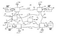
図2を参照すると、ネットワーク40は、通信リンク54〜70によって通信可能に結合された複数のネットワーク要素42〜52を含む。複数の装置72〜78が、対応する通信リンク(個別に特定せず)によって、様々な場所にて、即ち、ネットワーク40のネットワーク要素42〜52の幾つかに対し結合される。これらの装置は、点滅灯(flasher)72a〜d、点滅灯制御装置(レバースイッチ)74、アクセルペダル76、計器78等の1つ以上の計器等、任意の車両装置であってよい。 With reference to FIG. 2, the
通信リンク54〜70は、堅牢な輸送媒体であってよく、後述するシリアル通信アーキテクチャから転用され得る。即ち、通信リンク54〜70によって、ネットワーク要素間において信頼度が高いメッセージ転送を保証することが可能である。所定の通信リンク54〜70は、いずれも単一の双方向リンク、単一の単方向リンク、双方向リンク若しくは単方向リンクの組合せ、又は任意のリンク技術の組合せであってよい。更に、接続リンク54〜70は、配線又は光ファイバ等の有限媒体、自由な光又は無線周波数等の無限媒体、又はそれらの組合せであってよい。リンクは、CAN、LIN、FLEXRAY、J1850等の自動車環境用に設計された既存の堅牢な輸送メカニズムにより定義されてもよく、あるいは開発中若しくは後に開発されるトランスポート・プロトコルにより定義されてもよい。また、リンクは複数の技術の組合せであってもよく、他の実質的に任意のプロトコルに基づき指定されてもよい。 Communication links 54-70 may be robust transport media and may be diverted from the serial communication architecture described below. That is, the communication links 54 to 70 can guarantee message transfer with high reliability between network elements. Any given communication link 54-70 may be a single bidirectional link, a single unidirectional link, a bidirectional link or combination of unidirectional links, or any combination of link technologies. Further, the connecting links 54-70 may be finite media such as wiring or optical fiber, infinite media such as free light or radio frequency, or combinations thereof. The link may be defined by existing robust transport mechanisms designed for automotive environments such as CAN, LIN, FLEXRAY, J1850, etc., or may be defined by a transport protocol developed during or after development . Also, the link may be a combination of technologies and may be specified based on other substantially arbitrary protocols.
ネットワーク40は、何らかのレベルで、監視、制御、診断、及び他の関連する機能を提供するシステム管理機能を内蔵し得る。この機能は、ネットワーク40に結合された別個のエンティティを通して提供されたり、又はこの機能は、ネットワーク要素42〜52若しくはネットワーク40の他の適切な要素内に分散されたりしてよい。 The
ネットワーク要素42〜52及び接続リンク54〜70を連係させることによって、ネットワーク40に通信可能に接続された装置72〜78間の複数の通信経路が定義される。図3には、ネットワーク40によって提供される自由度を示す。この自由度の例として、点滅灯制御装置74から点滅灯72bに信号を通信するタスクを考える。ネットワーク40はパケットベースのネットワークであり、通信媒体にかかわらず、発信元から宛先への任意の利用可能な通信経路を使用できるようにする。図3に示すように、点滅灯制御装置74からの信号は、ネットワーク要素46及び44によって定義された点滅灯制御装置74とそれらを結合する通信リンク62との間の比較的まっすぐな経路82を通過し得る。経路82に沿って分断があり点滅灯制御装置74から点滅灯72bへのデータパケットの通信が阻害される場合、例えば、1つ以上の要素が最大出力である場合若しくは使用不可になった場合、又は経路82に沿って要素を結合する接続媒体に分断があった場合、ネットワーク要素46、42、44及び通信リンク58、54を介した経路84として示す新しい経路が用いられ得る。経路84は、点滅灯制御装置74と点滅灯72bとの間の通信を保証可能な通信経路として動的に生成されてもよく、又は予め定義されてもよい。ネットワーク要素46、50、52、44及び通信リンク64、68、56を介する更に他の経路86も用いられ得る。 By linking network elements 42-52 and connection links 54-70, a plurality of communication paths between devices 72-78 communicatively connected to
上例では、数多くの通信経路が定義され得ることを示す。複数の経路が利用可能であることによって、ネットワークは、トラフィックを管理して、通信リンク54〜70のうちの1つ以上の上の、あるいは、ネットワーク要素42〜52のうちの1つ以上における輻輳を回避し得る。また、複数の通信経路が利用可能であることにより、故障した要素/リンクを迂回して通信経路を確立することによって、1つ以上のネットワーク要素、通信リンク、又はその両方が故障した場合の耐故障性が可能になる。 The above example shows that many communication paths can be defined. By having multiple paths available, the network manages traffic and congestion on one or more of the communication links 54-70 or on one or more of the network elements 42-52. Can be avoided. Also, failure tolerance in the event of failure of one or more network elements, communication links, or both, by establishing a communication path bypassing the failed element / link due to the availability of multiple communication paths Sex becomes possible.
ここで図4を参照すると、ネットワーク140には、通信リンク154〜170によって通信可能に結合された複数のネットワーク要素142〜152が含まれる。複数の装置172〜178が、対応する通信リンク(個別に特定せず)によって、様々な場所で、即ち、ネットワーク140のネットワーク要素142〜152の幾つかに結合される。従来の装置182〜188、即ち、J1850、CAN、LIN、FLEXRAY、MOST等の既存の通信プロトコルによる通信に対し適合された装置もまたネットワーク140に結合される。例えば、ドアスイッチとして示す装置182及び184は、それぞれJ1850通信リンク192及び194によって、ネットワーク要素142及び144に接続され得る。この例ではドアロックである装置186及び188は、それぞれCAN通信リンク196及び198によってネットワーク要素150及び152に接続され得る。更に、いずれの通信リンクも、任意の適切な、好適には、堅牢なトランスポート・プロトコルに基づき指定され得る。図4に示すように、通信リンク196及び198は、CANプロトコルにより指定され、残りのリンクは、TCP/IP、CAN、LIN、FLEXRAY等により指定され得る。 Referring now to FIG. 4, the network 140 includes a plurality of network elements 142-152 communicatively coupled by communication links 154-170. A plurality of devices 172-178 are coupled to various locations, ie, some of the network elements 142-152 of the network 140 by corresponding communication links (not individually identified). Conventional devices 182-188, ie, devices adapted for communication over existing communication protocols such as J1850, CAN, LIN, FLEXRAY, MOST, etc. are also coupled to network 140. For example,
ネットワーク要素の構造は、図5に示すようであってよい。図5のネットワーク要素200には、1つをポート202として示す操作可能に結合された1つ以上の入出力ポート、プロセッサ204、及びメモリ206が含まれる。メモリ206は、関連するネットワークを通してデータパケットの通信を円滑化するように機能することをプロセッサに指示する制御プログラム(図示せず)を内蔵する。入出力ポート202は、通信リンクに接続され、ネットワーク要素200からデータパケットを送受信するように構成される。ネットワーク要素200は、複数の輸送媒体タイプに接続され得ることから、プロセッサは、制御プログラムに基づき動作して、第1輸送媒体を介して送信されるデータパケットを受け取り、第2輸送媒体を介した通信に必要なようにデータパケットを修正し、第2輸送媒体上でデータパケットの通信を行う。このようにして、ネットワーク要素は、異種の通信媒体間のプロキシ又はゲートウェイとして機能し得る。アプリケーションの要求に応じて、他のネットワーク要素が強化された機能又は簡略化された機能で用いられ得ることが認識されるであろう。例えば、ネットワーク要素が単一のプロトコルにより接続リンクを結合する場合、異種のプロトコルを取り扱うための処理能力は必要でなく、また、そのようなネットワーク要素は、データパケットに関連する情報のルートに基づき、単にデータパケットのルーティングを行うように構成され得る。 The structure of the network element may be as shown in FIG. The
本明細書に述べたネットワーク内通信に用いられるデータパケットには、パケットタイプ識別子、ルーティング情報、発信元ID情報、サービス品質(QoS)情報及びペイロードが含まれ得る。図6には、ネットワークにおいて用いられ得る代表的なデータパケット210を示す。データパケット210には、フレーム開始フィールド212、仲介フィールド214、制御フィールド216、データフィールド218、巡回冗長検査フィールド220、及びフレーム終止フィールド222が含まれ得る。仲介フィールド214は、パケットタイプ識別子224、ルートポインタ226、ポート識別子228、230、232、発信元ノード識別子234、及び優先度タグ236を含むように構成され得る。パケットタイプ224は、ベアラ、発見、通知、異常、制御等のデータパケットのタイプを識別する。データパケットがルート情報を含む場合、ルートポインタ226は現在のホップを指し、ホップ毎にデクリメントされる。ルートポインタ226には、また、他のタイプのルート情報が含まれ得る。ポート識別子228〜232は、ポート、例えば、データパケットが通過したネットワーク要素を識別し得る。発信元ノード234は情報発信元を識別する。優先度タグ236はサービス品質(QoS)要件用に予約でき、また、データパケットのサービスレベルを識別するコードを含み得る。制御フィールド216は、輸送媒体特有の制御データを含み得るが、例えば、データパケットが、CAN準拠通信装置から発せられたり又はそれに宛てられたりする場合、CAN制御データを含み得る。データフィールド218は、パケットによって搬送されるデータ、即ち、ペイロードを含む。 A data packet used for intra-network communication described herein may include a packet type identifier, routing information, source ID information, quality of service (QoS) information, and payload. FIG. 6 shows an
データパケット210は、発信元ルーティングを円滑化するように構成され得る、即ち、データパケットがネットワーク内を通過するルートは、情報発信元によって決定され、この経路情報は、データパケットそれ自体に含まれる。データパケット210は、宛先ルーティングを円滑化するようにも構成され得る、即ち、データパケットがネットワーク内を通過するルートは、各中間ノードによって決定され、次のノード情報は、データパケットに含まれ得る。
データパケット210は、CANデータパケット等の既知の通信パケット構造から転用され得る。図6に示すように、仲介フィールド214は、複数の異なるシリアル通信プロトコルにより、ネットワーク140内におけるデータパケットの通信を円滑化するように構成される。仲介フィールドは、ネットワーク140を通してデータパケット210を通信するためのルーティング情報を含むようにも構成され得る。即ち、情報はルートポインタ226フィールド内に含まれるか、そうでなければ仲介フィールド214内に含まれ得る。例えば、ルーティング情報は、ネットワーク140全体を通してデータパケットと共に残る固定ラベルであってよい。そして、ネットワーク140の各ネットワーク要素には、ラベルに基づきネットワーク140内においてデータパケットを導くテーブルが含まれる。他の選択肢として、パケットは、発信元でルーティングされてよく、そして、仲介フィールドには、ネットワーク全体の各ホップ用のルーティング情報が含まれ得る。更に、他の選択肢は、データパケット210、特に、仲介情報が、次のホップ用の情報を含むように、各ホップにおいてそれを修正することである。当然のことながら、データパケット210の他のフィールドを用いて、ルーティング情報、QoS情報、又は他のタイプの情報が搬送され得る。
ネットワーク40及び140は、既存の堅牢な通信媒体からの通信リンクを適応させることによって、既存の用途に実装され得る。図2〜3に示す具体例において、通信リンク54〜70は、CANプロトコルにより指定され得る。他の選択肢として、通信リンク54〜70は、LEN、FLEXRAY、J1850、MOST又は他のプロトコルにより指定され得る。図4に示す具体例では、通信リンク154〜170は、CAN、LIN、FLEXRAY、J1850、MOST等の任意の適切なプロトコルにより指定され得る。これらの各プロトコルは、仲介メカニズムを定義して、フロー制御の提供を可能とし得る。仲介を指定して、通信リンク上の優先度を最も高い優先度のメッセージに与え得る。優先度は、データパケット210の優先度タグ236等、メッセージヘッダ中のデータパケット内に示され得る。例えば、メッセージヘッダは、最も優勢なビットにゼロを含み得る。2つのネットワーク要素が同時に同じ通信リンク上で送信しようとする場合、最も高い優先度のメッセージ、例えば、優勢なビットの最小値が勝り他の全てが通信リンクを解放する。
ネットワーク40及び140等の本明細書に述べた実施形態によるネットワークの初期起動時、ネットワークの全てのノードを識別する必要がある。用語「ノード」は、ネットワーク40及び140に関連して述べたネットワーク要素に限定するものではなく、それらを含むネットワーク要素、スイッチ、ルータ、及び全ての結合される装置を意味し得る。また、特定のノードにとって関心のあるメッセージ識別子を識別し、各ノードに論理アドレスを割り当て、識別子対ノード論理アドレスの変換テーブルを生成し、ノードからノードへのルーティングテーブルを生成し、また、ノードからノードへの1つ以上のバックアップルートを生成する必要がある。幾つかのサービスレベルは、この所謂発見プロセスに関連付け得る。例えば、更に詳述するように、ネットワークは、マルチキャスト、暗号化又は他の能力が可能なノードを提示し得る。ノードは、情報を受信するように又は情報の利用可能性を通知するように構成され得る。 During initial startup of a network according to the embodiments described herein, such as
発見プロセスは、ネットワークに関連して知られており、通常用いられるダイクストラ(Dijkstra)アルゴリズムを採用して、ネットワーク発見プロセスを完成し、また、ルーティングテーブルを計算し得る。しかしながら、これら既知のプロセスでは、完全に動的なネットワークが仮定されており、各電源投入時又は任意の障害の検出時に全発見プロセスが完了される。ネットワークの規模に応じて、この発見プロセスは、数分の時間を要することがあり、このことは、ユーザが、車両に入り、それを始動し、それを直ちに操作することができることを期待する自動車環境において、又は車両が動作している間に異常が発生し、発見プロセスの完了の際の何らかの大幅な遅延が安全上の不安を引き起こす自動車環境においては、実用的でない。発見プロセスが完了するために数分間待たねばならないということは、欠陥と見なされ、ユーザや製造業者にとっては、容認できないものである。 The discovery process is known in the context of the network and employs the commonly used Dijkstra algorithm to complete the network discovery process and calculate the routing table. However, in these known processes, a fully dynamic network is assumed, and the entire discovery process is completed at each power up or detection of any failure. Depending on the size of the network, this discovery process may take a few minutes, which means that the user expects to be able to enter the vehicle, start it and operate it immediately It is impractical in the environment or in an automotive environment where anomalies occur while the vehicle is operating and any significant delay in completing the discovery process causes safety concerns. Having to wait a few minutes for the discovery process to complete is considered a defect and is unacceptable to users and manufacturers.
本明細書に述べた実施形態によるネットワークは、一般的に完全に動的ではなく、一般的に、ネットワークは障害検出時のみ動的になる。即ち、ネットワークは、何かが悪くなるまで動的ではなく、又は、新しいハードウェアがネットワークに追加された時のみ動的になる。従って、ネットワーク変化検出時、ネットワークの既知の最新状態が保存され、漸進的発見プロセスが用いられ得る。漸進的発見プロセスは、全体的なネットワーク性能にほとんど又は全く影響を及ぼさずに完了され得る。「車両ネットワークにおける発見プロセス」と題する米国特許出願第10/463,988号には、適切な発見プロセスが開示および記載されている。その開示を引用によって本明細書に援用する。 The network according to the embodiments described herein is generally not fully dynamic, and generally the network is dynamic only upon failure detection. That is, the network is not dynamic until something goes wrong, or only when new hardware is added to the network. Thus, upon detection of a network change, the known current state of the network is saved and an incremental discovery process can be used. The incremental discovery process can be completed with little or no impact on overall network performance. US patent application Ser. No. 10 / 463,988 entitled “Discovery Process in Vehicle Networks” discloses and describes a suitable discovery process. That disclosure is incorporated herein by reference.
本明細書に述べたネットワークアーキテクチャは、車両用途に用いられる既存のアーキテクチャより大きい自由度、信頼性、及び改善された通信能力を提供する。タイムスロットスイッチングを用いる具体例では、これらのネットワーク通信容量及び自由度は、更に強化され得る。現在の時間トリガ式バス構成では、ネットワークは、本質的にタイムスロットを有するバスである。ネットワーク要素は割り当てられたタイムスロットにメッセージを挿入することができるが、その割り当てられたタイムスロットにしか挿入できない。ネットワーク要素は、タイムスロットを割り当てられると、静的であり、タイムスロットはネットワーク全体において意味を有する。即ち、そのネットワーク要素だけが、そのタイムスロットにメッセージを挿入することができる。 The network architecture described herein provides greater flexibility, reliability, and improved communication capabilities than existing architectures used for vehicle applications. In embodiments using time slot switching, these network communication capacities and degrees of freedom can be further enhanced. In current time-triggered bus configurations, the network is essentially a bus with time slots. A network element can insert a message into an assigned time slot, but only into that assigned time slot. A network element is static when assigned a time slot, which has meaning in the entire network. That is, only that network element can insert a message into that time slot.
本発明の一実施形態に基づき、ネットワークは、ネットワーク要素がフレームのタイムスロットを切換えるように構成され、これにより、タイムスロットに挿入された情報は、その情報を必要とする再選択された要素/要素のグループによってのみ受信される。このことは、修正されたルーティングを統計的に割り当てることによって又は各データパケット内にルーティング情報を提供することによって、達成され得る。修正されたルーティング情報によって、中間ノードは、ネットワーク要素/ネットワーク要素のグループに対応して、第1タイムスロット割当から第2タイムスロット割当にパケットを切り換え、これにより、パケットは、所望のネットワーク要素/ネットワーク要素のグループにおいて最終的に終了し得る。 In accordance with one embodiment of the present invention, the network is configured such that the network element switches the time slot of the frame so that the information inserted in the time slot can be re-selected element / Received only by a group of elements. This can be achieved by statistically assigning modified routing or by providing routing information within each data packet. With the modified routing information, the intermediate node switches the packet from the first time slot assignment to the second time slot assignment corresponding to the network element / group of network elements, so that the packet is sent to the desired network element / It may eventually end in a group of network elements.
図7を参照すると、ネットワーク要素/ノード301は、スイッチ305及びスイッチ307を通して、ネットワーク要素/ノード303に情報を送信している。要素301/スイッチ305のリンク309上において、ペイロード、即ち、資源内において通信される情報及びデータは、第1リンク資源、例えば、リンク309のタイムスロット1を用いて通信される。ペイロードは、スイッチ305/スイッチ307のリンク311上の第2リンク資源、例えば、タイムスロット3を用いて通信され、また、第1リンク資源、例えば、タイムスロット1を用いて、スイッチ307/要素303のリンク313上で再度通信される。 Referring to FIG. 7, the network element /
スイッチ305/スイッチ307のリンク311は、複数の物理的なリンクを有し、スイッチ305/307は、リンク311が含まれる任意の物理リンクのあらゆる利用可能な資源上の要素301/303間でペイロードの切り換えが可能である。当然のことながら、リンク311上のマッピングは、任意の利用可能な資源、例えば、任意の利用可能なタイムスロットであってよい。更に、パケットが、宛先要素リンク、例えば、リンク313上の宛先ネットワーク要素用の適切なタイムスロットに切り換えられる限り、スイッチ305及び307を介してネットワーク要素301とネットワーク要素303との間で通信されるあらゆるペイロードは、リンク311上で同じ資源で送信される必要はない。 The
通信ネットワークの決定論的性質を保持することが望ましい場合や必要な場合もある。例えば、ネットワーク要素303は、タイムスロット1又は他のいずれかの割り当てられたタイムスロットによりペイロードを受信すると常に予想するように構成され得るが、以下の議論のため、このタイムスロットはタイムスロット1であると考えられる。従来的には、これは、ネットワーク要素303がタイムスロット1を割り当てられ、この割当がネットワーク全体で有意であることを意味している。即ち、ネットワーク要素303に情報を送信するあらゆる要素はペイロードをタイムスロット1に配置することによってこれを行い、ネットワーク要素303は常にタイムスロット1のペイロードを捜す。そのような構成は融通がきかず、また、ネットワーク資源を効率的に利用していない。図7に示すネットワークでは、資源の更により良い利用が提示される。しかしながら、ネットワークの決定論的性質を保持するには、即ち、割り当てられたタイムスロットを有するように構成されたネットワーク要素が情報を適切に受信することを保証するには、ネットワーク要素に情報を結合するリンク上の適切なタイムスロットに、ペイロードが存在することを保証する必要がある。図7に示す例の場合、このことは隣接するネットワーク要素、例えば、スイッチ307にタイムスロット割当データを提供することによって達成され得る。これによって、スイッチ307は、ネットワーク要素303に通信される情報を、その割り当てられたタイムスロットであるタイムスロット1に配置する。他の選択肢として、配信時、最終的に適切なタイムスロットにペイロードが存在することを保証するために、様々なネットワーク要素によって利用されるルート情報等の情報をペイロード自身が初期的に含んでもよく、又はルーティング中に含むように変更されてもよい。これら後の2つの可能性については、更に後述する。 It may be desirable or necessary to preserve the deterministic nature of the communication network. For example,
ネットワーク構成又は発見プロセス中、タイムスロット1に割り当てられるネットワーク要素303等、割り当てられるネットワーク資源を必要とするネットワーク装置には、適切に資源が割り当てられ、この情報は他のネットワーク要素に提供されてよい。ネットワーク資源に情報を送信する際、ペイロードは、送信前に資源割当情報を含むように構成され得る。次いで、この情報は、最終的に宛先ネットワーク要素に接続する通信ルートの最終レッグ上の適切なネットワーク資源にこの情報が配置されるように、送信側ネットワーク要素又は任意の中継ネットワーク要素によって用いられ得る。他の選択肢として、送信側ネットワーク要素は、宛先資源に対する任意の特定の割当要件を認識しない資源に情報を配置し得る。この場合、宛先ネットワーク要素に情報を通信するために用いられる中継ネットワーク要素のうちの1つ以上は、資源割当情報を含むように情報を修正する前、それが宛先ネットワーク要素に通信される前、又はその両方の前に、単に情報を適切な資源に配置し得る。 During a network configuration or discovery process, network devices that require network resources to be allocated, such as
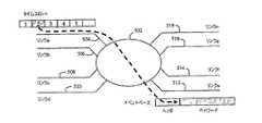
図8を参照すると、ノード402は、複数のタイムスロット式リンク404、406、408、410、412、414、416及び418に接続される。これらのタイムスロット式リンクは、FLEXRAYリンク等の任意の適切なタイプのタイムスロット式通信リンクであってよい。ノード402は、情報即ち第1リンク資源のペイロード、例えば、リンク404のタイムスロット2のペイロードを、他のリンク資源上の割り当てられたリンクタイムスロット、例えば、リンク412のタイムスロット6に転送する。この一方のリンク上の着信リンク資源と他方のリンク上の発信リンク資源との間の関連付けは、ペイロードに、例えば、ペイロードヘッダに含まれる情報を通して静的に若しくは動的に割り当てられるか又はネットワーク要素内に保持され得る。この関連付けは、帯域外信号送信(図示せず)によって割り当てられてもよい。動的な割当を用いる場合、リンク資源割当は、アドホックに行われ得る、即ち、各ペイロードは、それ自体の資源割当を受信する。他の選択肢として、永続的な関連付けが、組み立てられ、そして、通信が完了した後、即ち、全メッセージ又は情報の一部が通信された後、解体される。 Referring to FIG. 8,
図9を参照すると、ノード502は、複数のタイムスロット式リンク、例えば、リンク504、506、508及び510を複数のイベントトリガ式リンク、例えば、リンク512、514、516及び518に接続する。タイムスロット式リンクは、FLEXRAYリンク等の任意の適切なタイプのタイムスロット式通信リンクであってよく、他方、イベントトリガ式リンクは、CAN又は同様なリンクであってよい。ノード502は、1つのリンク上のタイムスロットのパケット又はフレーム等の情報ペイロード、例えば、リンク504のタイムスロット2のペイロードを、他のリンク、例えば、リンク512上のイベントトリガ式トランスポートフレームのペイロードに転送する。タイムスロット情報は、イベントトリガ式リンク上のノード502によってヘッダ情報に変換され、ペイロードの配信が可能となる。例えば、この情報は、通常のCAN識別情報であってよい。それは、また、スイッチファブリックが、リンク512に接続されたネットワーク上においてペイロードの更なるルーティングを行えるように定義されたルーティング情報であってよい。この実施形態は、時間トリガ式からイベントトリガ式の構成を示すが、逆もまた可能であり、イベントトリガ式ヘッダを発信リンク及びタイムスロットに変換してもよい。 Referring to FIG. 9,
例えば、図10を参照すると、ノード602は、複数のイベントトリガ式リンク、例えば、リンク604、606、608及び610を複数のタイムスロット式リンク、例えば、リンク612、614、616及び618に接続する。イベントトリガ式リンクは、CANリンク等の任意の適切なタイプのイベントベースの通信リンクであってよく、他方、タイムスロット式リンクは、FLEXRAY又は同様なリンクであってよい。ノード602は、リンク604等の1つのリンク上のイベントトリガ式トランスポートフレームの情報ペイロード、例えば、パケット又はフレームを、他のリンク上のタイムスロットのペイロード、例えば、リンク612のタイムスロット2のペイロードに転送する。ヘッダ情報は、タイムスロット式リンク上のノード602によってタイムスロット情報に変換され、ペイロードを配信し得る。例えば、この情報は、FLEXRAY情報であってよい。それは、また、スイッチファブリックが、リンク612に接続されたネットワーク上においてペイロードの更なるルーティングを行えるように定義されたルーティング情報であってよい。 For example, referring to FIG. 10,
車両内において情報を通信するための車両ネットワーク及び方法について記載した。ネットワークは、通信リンクによって結合された複数のネットワーク要素を含む。ネットワークに取り付けられた第1装置と第2装置との間で情報を通信するために、データフレームが提供される。ネットワークにおけるネットワーク要素は、ネットワーク要素の着信通信リンク上の第1資源をネットワーク要素の発信通信リンクの第2リンク資源にマッピングすることが可能である。更に、ネットワーク要素は着信通信リンクの第1リンク資源からデータフレームを受信し、また、発信通信リンクの第2リンク資源にデータフレームを通信するための複数のポートを有する。マッピングは、ネットワーク要素に記憶された情報に基づいて、又はデータフレームに記憶された情報に基づいてなど、静的に又は動的に行われ得る。本発明の上記説明は、例示のみであり、本出願から発行されるあらゆる特許の範囲を限定するものではない。本発明は、以下の請求項の範囲及び精神によってのみ限定されるものである。 A vehicle network and method for communicating information in a vehicle has been described. The network includes a plurality of network elements coupled by communication links. A data frame is provided for communicating information between a first device and a second device attached to the network. A network element in the network can map a first resource on the incoming communication link of the network element to a second link resource of the outgoing communication link of the network element. Further, the network element has a plurality of ports for receiving data frames from the first link resource of the incoming communication link and communicating data frames to the second link resource of the outgoing communication link. The mapping may be performed statically or dynamically, such as based on information stored in the network element or based on information stored in the data frame. The above description of the present invention is illustrative only and is not intended to limit the scope of any patent issued from this application. The present invention is limited only by the scope and spirit of the following claims.
Claims (21)
Translated fromJapaneseデータフレームを提供するデータフレーム提供工程と、
複数のネットワーク要素のうちの1つの着信通信リンク上の第1リンク資源を同ネットワーク要素の発信通信リンクの第2リンク資源にマッピングするマッピング工程と、第2リンク資源は第1リンク資源とは異なることと、同着信通信リンク及び同発信通信リンクのうちの一方又は両方はタイムスロット式通信リンクであることと、
前記着信通信リンクの第1リンク資源からデータフレームを受信し、前記発信通信リンクの第2リンク資源に同データフレームを通信する通信工程と、からなる方法。A method for communicating information in a vehicle including a network including a plurality of network elements communicatively linked by a communication link, comprising:
A data frame providing step for providing a data frame;
A mapping step of mapping a first link resource on one incoming communication link of a plurality of network elements to a second link resource of an outgoing communication link of the network element; and the second link resource is different from the first link resource And one or both of the incoming communication link and the outgoing communication link are timeslot communication links;
Receiving a data frame from a first link resource of the incoming communication link and communicating the data frame to a second link resource of the outgoing communication link.
前記ネットワーク要素のうちの1つ以上に接続された第1装置と前記ネットワーク要素のうちの1つ以上に接続された第2装置との間で情報を通信するためのデータフレームと、
前記ネットワーク要素のうちの1つ以上におけるプロセッサと、同プロセッサはネットワーク要素の着信通信リンク上の第1資源をネットワーク要素の発信通信リンクの第2リンク資源にマッピング可能であることと、
着信通信リンクの第1リンク資源からデータフレームを受信するための前記ネットワーク要素のうちの1つ以上における1つ以上のポートと、発信通信リンクの第2リンク資源にデータフレームを通信するための前記ネットワーク要素のうちの1つ以上における1つ以上のポートと、からなる車両ネットワーク。A plurality of network elements coupled by communication links;
A data frame for communicating information between a first device connected to one or more of the network elements and a second device connected to one or more of the network elements;
A processor in one or more of the network elements, the processor being capable of mapping a first resource on the incoming communication link of the network element to a second link resource of the outgoing communication link of the network element;
One or more ports in one or more of the network elements for receiving data frames from a first link resource of an incoming communication link, and the data for communicating data frames to a second link resource of an outgoing communication link A vehicle network comprising one or more ports in one or more of the network elements.
第1タイムスロット割当に割り当てられたデータパケットを第1リンクから受信するパケット受信工程と、
データパケットに対する第2タイムスロット割当を決定するタイムスロット割当決定工程と、第2タイムスロット割当は第1タイムスロット割当と異なることと、
第2タイムスロット割当に割り当てられたデータパケットを第2リンク上で送信するパケット送信工程と、からなる方法。A method for communicating information in a vehicle including a network including a plurality of network elements communicatively linked by a communication link, comprising:
Receiving a data packet assigned to the first time slot assignment from the first link;
A time slot assignment determining step for determining a second time slot assignment for the data packet; the second time slot assignment being different from the first time slot assignment;
A packet transmission step of transmitting a data packet allocated to the second time slot allocation on the second link.
Applications Claiming Priority (2)
| Application Number | Priority Date | Filing Date | Title |
|---|---|---|---|
| US11/125,791US7733841B2 (en) | 2005-05-10 | 2005-05-10 | Vehicle network with time slotted access and method |
| PCT/US2006/015754WO2006121613A2 (en) | 2005-05-10 | 2006-04-26 | Vehicle network with time slotted access and method |
Publications (1)
| Publication Number | Publication Date |
|---|---|
| JP2008541614Atrue JP2008541614A (en) | 2008-11-20 |
Family
ID=37397054
Family Applications (1)
| Application Number | Title | Priority Date | Filing Date |
|---|---|---|---|
| JP2008511144APendingJP2008541614A (en) | 2005-05-10 | 2006-04-26 | Vehicle network and method with time slot access |
Country Status (4)
| Country | Link |
|---|---|
| US (1) | US7733841B2 (en) |
| EP (1) | EP1886214B1 (en) |
| JP (1) | JP2008541614A (en) |
| WO (1) | WO2006121613A2 (en) |
Cited By (5)
| Publication number | Priority date | Publication date | Assignee | Title |
|---|---|---|---|---|
| JP2010206837A (en)* | 2010-05-25 | 2010-09-16 | Moeller Gmbh | Method and switching device for controlling device connected in bus network through opened field bus |
| KR101462551B1 (en)* | 2010-11-03 | 2014-11-18 | 브로드콤 코포레이션 | Vehicle communication network |
| US8935435B2 (en) | 2007-07-06 | 2015-01-13 | Eaton Electrical Ip Gmbh & Co. Kg | System and method for controlling bus-networked devices via an open field bus |
| JP2015522982A (en)* | 2012-05-15 | 2015-08-06 | エフテーエス コンピューターテヒニク ゲゼルシャフト ミット ベシュレンクテル ハフツング | Method and apparatus for relaying time trigger messages and event trigger messages |
| WO2020122279A1 (en)* | 2018-12-13 | 2020-06-18 | 엘지전자 주식회사 | Vehicle system |
Families Citing this family (15)
| Publication number | Priority date | Publication date | Assignee | Title |
|---|---|---|---|---|
| WO2006131879A2 (en)* | 2005-06-09 | 2006-12-14 | Nxp B.V. | Storage unit for a communication system node, method for data storage and communication system node |
| CN101305566A (en)* | 2005-09-13 | 2008-11-12 | Nxp股份有限公司 | Message transmission method |
| CN101512987A (en)* | 2006-09-06 | 2009-08-19 | Nxp股份有限公司 | Cluster couplers in time-triggered networks |
| JP4950704B2 (en)* | 2007-03-06 | 2012-06-13 | 株式会社オートネットワーク技術研究所 | In-vehicle relay connection unit |
| US8130773B2 (en)* | 2008-06-25 | 2012-03-06 | Honeywell International Inc. | Hybrid topology ethernet architecture |
| FR2945171B1 (en)* | 2009-04-29 | 2011-06-10 | Peugeot Citroen Automobiles Sa | METHOD FOR TRANSMITTING MESSAGES |
| US8184555B1 (en)* | 2009-06-24 | 2012-05-22 | The Boeing Company | SpaceWire network management |
| DE102010023071B4 (en)* | 2009-10-01 | 2017-10-19 | Volkswagen Ag | Method and network node for transmitting event-driven messages |
| DE102012201669B4 (en)* | 2012-02-10 | 2021-05-06 | Robert Bosch Gmbh | Method and communication controller for data transmission between two data processing units connected by means of transmission links |
| US9215168B2 (en) | 2012-07-23 | 2015-12-15 | Broadcom Corporation | Controller area network communications using ethernet |
| EP2741452A1 (en)* | 2012-12-10 | 2014-06-11 | Robert Bosch Gmbh | Method for data transmission among ECUs and/or measuring devices |
| US10158966B2 (en) | 2014-11-05 | 2018-12-18 | At&T Intellectual Property I, L.P. | Connected car data links aggregator |
| JP6532789B2 (en)* | 2015-09-03 | 2019-06-19 | 日立オートモティブシステムズ株式会社 | Gateway apparatus and computing apparatus |
| DE102018205264B3 (en) | 2018-04-09 | 2019-10-10 | Continental Automotive Gmbh | Method for operating an Ethernet electrical system of a motor vehicle, control unit and Ethernet electrical system |
| KR20230084959A (en)* | 2021-12-06 | 2023-06-13 | 현대자동차주식회사 | Gateway and method for processing can message thereof |
Citations (7)
| Publication number | Priority date | Publication date | Assignee | Title |
|---|---|---|---|---|
| JPH03247049A (en)* | 1990-02-23 | 1991-11-05 | Furukawa Electric Co Ltd:The | Multiplex transmission method |
| JPH05300570A (en)* | 1992-04-17 | 1993-11-12 | Mazda Motor Corp | Multiplex transmitting device |
| JPH0746665A (en)* | 1993-07-30 | 1995-02-14 | Mazda Motor Corp | Multiplex transmitter |
| JPH09149063A (en)* | 1995-11-24 | 1997-06-06 | Nec Corp | Ring type network |
| WO2001045329A1 (en)* | 1999-12-15 | 2001-06-21 | Hitachi, Ltd. | Gateway and distributed system using the gateway |
| WO2003021889A1 (en)* | 2001-08-31 | 2003-03-13 | Motorola, Inc. A Corporation Of The State Of Delaware | Vehicle active network using multiple communication paths |
| WO2004051925A2 (en)* | 2002-12-03 | 2004-06-17 | Freescale Semiconductor, Inc. | System node and method for providing media arbitration in a time-slotted system |
Family Cites Families (73)
| Publication number | Priority date | Publication date | Assignee | Title |
|---|---|---|---|---|
| US4736367A (en)* | 1986-12-22 | 1988-04-05 | Chrysler Motors Corporation | Smart control and sensor devices single wire bus multiplex system |
| US7606575B2 (en)* | 1988-08-04 | 2009-10-20 | Broadcom Corporation | Remote radio data communication system with data rate switching |
| US4907222A (en)* | 1988-08-17 | 1990-03-06 | Nuvatec, Inc. | Vehicle multiplex system |
| DE3934974A1 (en)* | 1989-08-08 | 1991-02-14 | Bosch Gmbh Robert | DEVICE FOR THE FUNCTIONAL CONTROL OF SEVERAL CONTROL UNITS IN A MOTOR VEHICLE |
| US4964120A (en)* | 1989-09-08 | 1990-10-16 | Honeywell Inc. | Method of detecting a cable fault and switching to a redundant cable in a universal local area network |
| JP2904297B2 (en)* | 1990-03-30 | 1999-06-14 | マツダ株式会社 | Multiplex transmission equipment for vehicles |
| US5710798A (en)* | 1992-03-12 | 1998-01-20 | Ntp Incorporated | System for wireless transmission and receiving of information and method of operation thereof |
| US5323385A (en)* | 1993-01-27 | 1994-06-21 | Thermo King Corporation | Serial bus communication method in a refrigeration system |
| WO1994026558A1 (en)* | 1993-05-07 | 1994-11-24 | Oztech Industries Pty. Limited | Vehicle communication/control system |
| US6236940B1 (en)* | 1995-09-08 | 2001-05-22 | Prolink, Inc. | Display monitor for golf cart yardage and information system |
| US5794164A (en)* | 1995-11-29 | 1998-08-11 | Microsoft Corporation | Vehicle computer system |
| US5732074A (en)* | 1996-01-16 | 1998-03-24 | Cellport Labs, Inc. | Mobile portable wireless communication system |
| US6111888A (en)* | 1997-05-27 | 2000-08-29 | Micro Motion, Inc. | Deterministic serial bus communication system |
| US20020150050A1 (en)* | 1999-06-17 | 2002-10-17 | Nathanson Martin D. | Automotive telemetry protocol |
| US6330236B1 (en)* | 1998-06-11 | 2001-12-11 | Synchrodyne Networks, Inc. | Packet switching method with time-based routing |
| US20050058149A1 (en)* | 1998-08-19 | 2005-03-17 | Howe Wayne Richard | Time-scheduled and time-reservation packet switching |
| US6665601B1 (en)* | 1998-12-22 | 2003-12-16 | Case Corporation | Communications system for managing messages across a vehicle data bus |
| US6177867B1 (en)* | 1999-04-09 | 2001-01-23 | Eaton Corporation | System for wireless communication between components of a vehicle |
| US6430164B1 (en)* | 1999-06-17 | 2002-08-06 | Cellport Systems, Inc. | Communications involving disparate protocol network/bus and device subsystems |
| US6356823B1 (en)* | 1999-11-01 | 2002-03-12 | Itt Research Institute | System for monitoring and recording motor vehicle operating parameters and other data |
| US6526335B1 (en)* | 2000-01-24 | 2003-02-25 | G. Victor Treyz | Automobile personal computer systems |
| US20030093798A1 (en)* | 2000-07-10 | 2003-05-15 | Michael Rogerson | Modular entertainment system configured for multiple broadband content delivery incorporating a distributed server |
| US6738701B2 (en)* | 2000-07-14 | 2004-05-18 | International Truck Intellectual Property Company, Llc | Gear shifter to transmission interface and control sub-system |
| US6559783B1 (en)* | 2000-08-16 | 2003-05-06 | Microchip Technology Incorporated | Programmable auto-converting analog to digital conversion module |
| NO315248B1 (en)* | 2000-12-15 | 2003-08-04 | Knutsen Oas Shipping As | Gas bottle device |
| US20030051131A1 (en)* | 2001-08-31 | 2003-03-13 | Juergen Reinold | Vehicle active network with data encryption |
| US6885916B2 (en)* | 2001-08-31 | 2005-04-26 | Motorola, Inc. | Data packet for a vehicle active network |
| US7173903B2 (en)* | 2001-08-31 | 2007-02-06 | Temic Automotive Of North America, Inc. | Vehicle active network with communication path redundancy |
| US7415508B2 (en)* | 2001-08-31 | 2008-08-19 | Temic Automotive Of North America, Inc. | Linked vehicle active networks |
| US8194536B2 (en)* | 2001-08-31 | 2012-06-05 | Continental Automotive Systems, Inc. | Vehicle active network with fault tolerant devices |
| US6747365B2 (en)* | 2001-08-31 | 2004-06-08 | Motorola, Inc. | Vehicle active network adapted to legacy architecture |
| US20030043824A1 (en)* | 2001-08-31 | 2003-03-06 | Remboski Donald J. | Vehicle active network and device |
| US20030045234A1 (en)* | 2001-08-31 | 2003-03-06 | Remboski Donald J. | Vehicle active network with reserved portions |
| US7170853B2 (en)* | 2001-08-31 | 2007-01-30 | Temic Automotive Of North America, Inc. | Vehicle active network topologies |
| US7027387B2 (en)* | 2001-08-31 | 2006-04-11 | Motorola, Inc. | Vehicle active network with data redundancy |
| US6931004B2 (en)* | 2001-08-31 | 2005-08-16 | Motorola, Inc. | Vehicle active network with backbone structure |
| US20030065630A1 (en)* | 2001-10-02 | 2003-04-03 | International Business Machines Corporation | Adjusting an amount owed for fueling based on vehicle characteristics |
| US20030230443A1 (en)* | 2002-01-08 | 2003-12-18 | David Cramer | Advanced composite hybrid-electric vehicle |
| DE10206875A1 (en)* | 2002-02-18 | 2003-08-28 | Philips Intellectual Property | Method and circuit arrangement for monitoring and managing the data traffic in a communication system with several communication nodes |
| US20030222982A1 (en)* | 2002-03-28 | 2003-12-04 | Hamdan Majil M. | Integrated video/data information system and method for application to commercial vehicles to enhance driver awareness |
| EP1355456A1 (en)* | 2002-04-16 | 2003-10-22 | Robert Bosch Gmbh | FlexRay communication protocol |
| ATE306163T1 (en)* | 2002-04-16 | 2005-10-15 | Bosch Gmbh Robert | METHOD FOR MONITORING AN ACCESS PROCESS CONTROL FOR A COMMUNICATIONS MEDIUM A COMMUNICATIONS CONTROL OF A COMMUNICATIONS SYSTEM |
| US20040043824A1 (en)* | 2002-06-08 | 2004-03-04 | Nicholas Uzelac | Swing training device |
| US20040003232A1 (en)* | 2002-06-28 | 2004-01-01 | Levenson Samuel M. | Method and system for vehicle component authentication of another vehicle component |
| US6839710B2 (en)* | 2002-06-28 | 2005-01-04 | Motorola, Inc. | Method and system for maintaining a configuration history of a vehicle |
| US20040001593A1 (en)* | 2002-06-28 | 2004-01-01 | Jurgen Reinold | Method and system for component obtainment of vehicle authentication |
| US7228420B2 (en)* | 2002-06-28 | 2007-06-05 | Temic Automotive Of North America, Inc. | Method and system for technician authentication of a vehicle |
| US7325135B2 (en)* | 2002-06-28 | 2008-01-29 | Temic Automotive Of North America, Inc. | Method and system for authorizing reconfiguration of a vehicle |
| US20040003234A1 (en)* | 2002-06-28 | 2004-01-01 | Jurgen Reinold | Method and system for vehicle authentication of a subassembly |
| US7600114B2 (en)* | 2002-06-28 | 2009-10-06 | Temic Automotive Of North America, Inc. | Method and system for vehicle authentication of another vehicle |
| US7127611B2 (en)* | 2002-06-28 | 2006-10-24 | Motorola, Inc. | Method and system for vehicle authentication of a component class |
| US7549046B2 (en)* | 2002-06-28 | 2009-06-16 | Temic Automotive Of North America, Inc. | Method and system for vehicle authorization of a service technician |
| US7137001B2 (en)* | 2002-06-28 | 2006-11-14 | Motorola, Inc. | Authentication of vehicle components |
| US7010682B2 (en)* | 2002-06-28 | 2006-03-07 | Motorola, Inc. | Method and system for vehicle authentication of a component |
| US7137142B2 (en)* | 2002-06-28 | 2006-11-14 | Motorola, Inc. | Method and system for vehicle authentication of a component using key separation |
| US20040003230A1 (en)* | 2002-06-28 | 2004-01-01 | Puhl Larry C. | Method and system for vehicle authentication of a service technician |
| US7131005B2 (en)* | 2002-06-28 | 2006-10-31 | Motorola, Inc. | Method and system for component authentication of a vehicle |
| US7076665B2 (en)* | 2002-06-28 | 2006-07-11 | Motorola, Inc. | Method and system for vehicle subassembly authentication of a component |
| US7181615B2 (en)* | 2002-06-28 | 2007-02-20 | Motorola, Inc. | Method and system for vehicle authentication of a remote access device |
| AT5705U3 (en)* | 2002-07-04 | 2003-06-25 | Plasser Bahnbaumasch Franz | STAMPING MACHINE WITH A MACHINE AND AGGREGATE FRAME |
| US7113759B2 (en)* | 2002-08-28 | 2006-09-26 | Texas Instruments Incorporated | Controller area network transceiver having capacitive balancing circuit for improved receiver common-mode rejection |
| SE524201C2 (en)* | 2002-12-17 | 2004-07-06 | Lars-Berno Fredriksson | Device for distributed control and monitoring system |
| US7310327B2 (en)* | 2003-04-28 | 2007-12-18 | Temic Automotive Of North America, Inc. | Method and apparatus for time synchronizing an in-vehicle network |
| US7999408B2 (en)* | 2003-05-16 | 2011-08-16 | Continental Automotive Systems, Inc. | Power and communication architecture for a vehicle |
| US7570597B2 (en)* | 2003-06-12 | 2009-08-04 | Temic Automotive Of North America, Inc. | Discovery process in a vehicle network |
| US7593344B2 (en)* | 2004-10-14 | 2009-09-22 | Temic Automotive Of North America, Inc. | System and method for reprogramming nodes in an automotive switch fabric network |
| US7593429B2 (en)* | 2004-10-14 | 2009-09-22 | Temic Automotive Of North America, Inc. | System and method for time synchronizing nodes in an automotive network using input capture |
| US7623552B2 (en)* | 2004-10-14 | 2009-11-24 | Temic Automotive Of North America, Inc. | System and method for time synchronizing nodes in an automotive network using input capture |
| US20060083172A1 (en)* | 2004-10-14 | 2006-04-20 | Jordan Patrick D | System and method for evaluating the performance of an automotive switch fabric network |
| US7599377B2 (en)* | 2004-10-15 | 2009-10-06 | Temic Automotive Of North America, Inc. | System and method for tunneling standard bus protocol messages through an automotive switch fabric network |
| US7613190B2 (en)* | 2004-10-18 | 2009-11-03 | Temic Automotive Of North America, Inc. | System and method for streaming sequential data through an automotive switch fabric |
| EP1672505A3 (en)* | 2004-12-20 | 2012-07-04 | BWI Company Limited S.A. | Fail-silent node architecture |
| US7324892B2 (en)* | 2005-04-08 | 2008-01-29 | Temic Automotive Of North America, Inc. | Parameter coordination in a vehicular communication network |
- 2005
- 2005-05-10USUS11/125,791patent/US7733841B2/enactiveActive
- 2006
- 2006-04-26WOPCT/US2006/015754patent/WO2006121613A2/enactiveApplication Filing
- 2006-04-26JPJP2008511144Apatent/JP2008541614A/enactivePending
- 2006-04-26EPEP06751453.9Apatent/EP1886214B1/enactiveActive
Patent Citations (7)
| Publication number | Priority date | Publication date | Assignee | Title |
|---|---|---|---|---|
| JPH03247049A (en)* | 1990-02-23 | 1991-11-05 | Furukawa Electric Co Ltd:The | Multiplex transmission method |
| JPH05300570A (en)* | 1992-04-17 | 1993-11-12 | Mazda Motor Corp | Multiplex transmitting device |
| JPH0746665A (en)* | 1993-07-30 | 1995-02-14 | Mazda Motor Corp | Multiplex transmitter |
| JPH09149063A (en)* | 1995-11-24 | 1997-06-06 | Nec Corp | Ring type network |
| WO2001045329A1 (en)* | 1999-12-15 | 2001-06-21 | Hitachi, Ltd. | Gateway and distributed system using the gateway |
| WO2003021889A1 (en)* | 2001-08-31 | 2003-03-13 | Motorola, Inc. A Corporation Of The State Of Delaware | Vehicle active network using multiple communication paths |
| WO2004051925A2 (en)* | 2002-12-03 | 2004-06-17 | Freescale Semiconductor, Inc. | System node and method for providing media arbitration in a time-slotted system |
Cited By (9)
| Publication number | Priority date | Publication date | Assignee | Title |
|---|---|---|---|---|
| US8935435B2 (en) | 2007-07-06 | 2015-01-13 | Eaton Electrical Ip Gmbh & Co. Kg | System and method for controlling bus-networked devices via an open field bus |
| US9164934B2 (en) | 2007-07-06 | 2015-10-20 | Eaton Electrical Ip Gmbh & Co. Kg | System and method for controlling bus-networked devices via an open field bus |
| US10599604B2 (en) | 2007-07-06 | 2020-03-24 | Eaton Intelligent Power Unlimited | System and method for controlling bus-networked devices via an open field bus |
| US11182327B2 (en) | 2007-07-06 | 2021-11-23 | Eaton Intelligent Power Limited | System and method for controlling bus-networked devices via an open field bus |
| JP2010206837A (en)* | 2010-05-25 | 2010-09-16 | Moeller Gmbh | Method and switching device for controlling device connected in bus network through opened field bus |
| KR101462551B1 (en)* | 2010-11-03 | 2014-11-18 | 브로드콤 코포레이션 | Vehicle communication network |
| US9215124B2 (en) | 2010-11-03 | 2015-12-15 | Broadcom Corporation | Unified vehicle network frame protocol |
| JP2015522982A (en)* | 2012-05-15 | 2015-08-06 | エフテーエス コンピューターテヒニク ゲゼルシャフト ミット ベシュレンクテル ハフツング | Method and apparatus for relaying time trigger messages and event trigger messages |
| WO2020122279A1 (en)* | 2018-12-13 | 2020-06-18 | 엘지전자 주식회사 | Vehicle system |
Also Published As
| Publication number | Publication date |
|---|---|
| US7733841B2 (en) | 2010-06-08 |
| WO2006121613A3 (en) | 2007-11-15 |
| WO2006121613A2 (en) | 2006-11-16 |
| EP1886214A4 (en) | 2012-08-22 |
| EP1886214A2 (en) | 2008-02-13 |
| EP1886214B1 (en) | 2014-08-06 |
| US20060259204A1 (en) | 2006-11-16 |
Similar Documents
| Publication | Publication Date | Title |
|---|---|---|
| JP2008541614A (en) | Vehicle network and method with time slot access | |
| US6934612B2 (en) | Vehicle network and communication method in a vehicle network | |
| CN108370343B (en) | Network hub, transfer method, and in-vehicle network system | |
| US7391719B2 (en) | Redundant network interface for ethernet devices | |
| JP7192074B2 (en) | Network hub, transfer method and in-vehicle network system | |
| JP2008517527A (en) | System and method for evaluating the performance of automotive switch configuration networks | |
| US10992599B2 (en) | Communication method of ethernet network for vehicle | |
| KR20160096526A (en) | Method for diagnosing network and apparatus for the same | |
| JP4705492B2 (en) | Ring node device and ring node redundancy method | |
| JPH088975A (en) | Local area network interconnected system and device | |
| JP4109693B2 (en) | Node, RPR interface card and optical network system | |
| US6771645B1 (en) | Packet relaying apparatus | |
| KR19990077415A (en) | Network system | |
| US20200296165A1 (en) | Method and device for operating a communication system | |
| Häckel et al. | Dynamic service-orientation for software-defined in-vehicle networks | |
| KR100768418B1 (en) | Vehicle network and method of communicating data packets in a vehicle network | |
| JP3529541B2 (en) | Router device and packet transfer method | |
| JP5542628B2 (en) | Information transmission system, train transmission system | |
| JP3800338B2 (en) | Communication control system | |
| Nagaraj et al. | On the importance of traffic control subsystem in icn-based industrial networks | |
| Heise et al. | Self-configuring real-time communication network based on openflow | |
| KR100218666B1 (en) | How to Create Path Control Tags for Multilevel Interconnect Networks | |
| CN119071218A (en) | Method and device for publishing information, method and device for obtaining forwarded information | |
| JPWO2006009109A1 (en) | Bridge, transmitter, and information system |
Legal Events
| Date | Code | Title | Description |
|---|---|---|---|
| A977 | Report on retrieval | Free format text:JAPANESE INTERMEDIATE CODE: A971007 Effective date:20100802 | |
| A131 | Notification of reasons for refusal | Free format text:JAPANESE INTERMEDIATE CODE: A131 Effective date:20100810 | |
| A02 | Decision of refusal | Free format text:JAPANESE INTERMEDIATE CODE: A02 Effective date:20110118 |