JP2008541096A - Apparatus, system, and method capable of performing spectral domain optical coherence reflectometry for sensitive detection of chemical and biological samples - Google Patents
Apparatus, system, and method capable of performing spectral domain optical coherence reflectometry for sensitive detection of chemical and biological samplesDownload PDFInfo
- Publication number
- JP2008541096A JP2008541096AJP2008511472AJP2008511472AJP2008541096AJP 2008541096 AJP2008541096 AJP 2008541096AJP 2008511472 AJP2008511472 AJP 2008511472AJP 2008511472 AJP2008511472 AJP 2008511472AJP 2008541096 AJP2008541096 AJP 2008541096A
- Authority
- JP
- Japan
- Prior art keywords
- electromagnetic radiation
- sample
- change
- thickness
- radiation
- Prior art date
- Legal status (The legal status is an assumption and is not a legal conclusion. Google has not performed a legal analysis and makes no representation as to the accuracy of the status listed.)
- Withdrawn
Links
- 238000000034methodMethods0.000titleclaimsabstractdescription38
- 230000003595spectral effectEffects0.000titleclaimsabstractdescription10
- 230000003287optical effectEffects0.000titleclaimsdescription8
- 239000000126substanceSubstances0.000titledescription4
- 238000011896sensitive detectionMethods0.000titledescription2
- 239000012472biological sampleSubstances0.000title1
- 238000002310reflectometryMethods0.000title1
- 230000008859changeEffects0.000claimsabstractdescription52
- 230000005670electromagnetic radiationEffects0.000claimsabstractdescription41
- 230000005855radiationEffects0.000claimsabstractdescription19
- 230000027455bindingEffects0.000claimsdescription16
- 238000010494dissociation reactionMethods0.000claimsdescription2
- 230000005593dissociationsEffects0.000claimsdescription2
- 230000004907fluxEffects0.000claims3
- 239000000523sampleSubstances0.000description33
- 238000005259measurementMethods0.000description25
- 238000001514detection methodMethods0.000description24
- 108010090804StreptavidinProteins0.000description18
- 108090000623proteins and genesProteins0.000description13
- 102000004169proteins and genesHuman genes0.000description13
- 239000000243solutionSubstances0.000description12
- KRHYYFGTRYWZRS-UHFFFAOYSA-NFluoraneChemical compoundFKRHYYFGTRYWZRS-UHFFFAOYSA-N0.000description11
- 230000009878intermolecular interactionEffects0.000description10
- QPJSUIGXIBEQAC-UHFFFAOYSA-Nn-(2,4-dichloro-5-propan-2-yloxyphenyl)acetamideChemical compoundCC(C)OC1=CC(NC(C)=O)=C(Cl)C=C1ClQPJSUIGXIBEQAC-UHFFFAOYSA-N0.000description9
- YBJHBAHKTGYVGT-ZKWXMUAHSA-N(+)-BiotinChemical compoundN1C(=O)N[C@@H]2[C@H](CCCCC(=O)O)SC[C@@H]21YBJHBAHKTGYVGT-ZKWXMUAHSA-N0.000description6
- 238000010521absorption reactionMethods0.000description6
- 238000010586diagramMethods0.000description6
- 230000006870functionEffects0.000description6
- 239000010410layerSubstances0.000description6
- 230000035945sensitivityEffects0.000description6
- 241000894007speciesSpecies0.000description6
- 238000005516engineering processMethods0.000description5
- 239000011521glassSubstances0.000description5
- 238000003384imaging methodMethods0.000description5
- 230000000243photosynthetic effectEffects0.000description5
- VYPSYNLAJGMNEJ-UHFFFAOYSA-Nsilicon dioxideInorganic materialsO=[Si]=OVYPSYNLAJGMNEJ-UHFFFAOYSA-N0.000description5
- 239000012491analyteSubstances0.000description4
- 238000009792diffusion processMethods0.000description4
- LOKCTEFSRHRXRJ-UHFFFAOYSA-Idipotassium trisodium dihydrogen phosphate hydrogen phosphate dichlorideChemical compoundP(=O)(O)(O)[O-].[K+].P(=O)(O)([O-])[O-].[Na+].[Na+].[Cl-].[K+].[Cl-].[Na+]LOKCTEFSRHRXRJ-UHFFFAOYSA-I0.000description4
- 238000009826distributionMethods0.000description4
- 239000012530fluidSubstances0.000description4
- 230000009149molecular bindingEffects0.000description4
- 239000002953phosphate buffered salineSubstances0.000description4
- 238000002198surface plasmon resonance spectroscopyMethods0.000description4
- 229910004298SiO 2Inorganic materials0.000description3
- 230000004913activationEffects0.000description3
- 229960002685biotinDrugs0.000description3
- 235000020958biotinNutrition0.000description3
- 239000011616biotinSubstances0.000description3
- 239000000835fiberSubstances0.000description3
- 230000003993interactionEffects0.000description3
- 238000002493microarrayMethods0.000description3
- 238000012014optical coherence tomographyMethods0.000description3
- 238000000926separation methodMethods0.000description3
- 235000012239silicon dioxideNutrition0.000description3
- XLYOFNOQVPJJNP-UHFFFAOYSA-NwaterSubstancesOXLYOFNOQVPJJNP-UHFFFAOYSA-N0.000description3
- 241000700605VirusesSpecies0.000description2
- 230000008901benefitEffects0.000description2
- 238000002508contact lithographyMethods0.000description2
- 239000013078crystalSubstances0.000description2
- 230000007123defenseEffects0.000description2
- 239000008367deionised waterSubstances0.000description2
- 229910021641deionized waterInorganic materials0.000description2
- 239000004205dimethyl polysiloxaneSubstances0.000description2
- 230000007613environmental effectEffects0.000description2
- 238000002474experimental methodMethods0.000description2
- 239000000463materialSubstances0.000description2
- 238000000813microcontact printingMethods0.000description2
- 229920000435poly(dimethylsiloxane)Polymers0.000description2
- 230000008929regenerationEffects0.000description2
- 238000011069regeneration methodMethods0.000description2
- 238000012552reviewMethods0.000description2
- 239000000377silicon dioxideSubstances0.000description2
- 238000001228spectrumMethods0.000description2
- HRPVXLWXLXDGHG-UHFFFAOYSA-NAcrylamideChemical compoundNC(=O)C=CHRPVXLWXLXDGHG-UHFFFAOYSA-N0.000description1
- 241000193738Bacillus anthracisSpecies0.000description1
- 108091003079Bovine Serum AlbuminProteins0.000description1
- 238000000018DNA microarrayMethods0.000description1
- 108010043121Green Fluorescent ProteinsProteins0.000description1
- 102000004144Green Fluorescent ProteinsHuman genes0.000description1
- 208000007479Orofaciodigital syndrome type 1Diseases0.000description1
- 241000219315SpinaciaSpecies0.000description1
- 235000009337Spinacia oleraceaNutrition0.000description1
- 238000003491arrayMethods0.000description1
- 230000015572biosynthetic processEffects0.000description1
- 229940098773bovine serum albuminDrugs0.000description1
- 239000007853buffer solutionSubstances0.000description1
- 239000013626chemical specieSubstances0.000description1
- 238000005229chemical vapour depositionMethods0.000description1
- 230000009260cross reactivityEffects0.000description1
- 238000004925denaturationMethods0.000description1
- 230000036425denaturationEffects0.000description1
- 230000033310detection of chemical stimulusEffects0.000description1
- 230000000694effectsEffects0.000description1
- 238000005566electron beam evaporationMethods0.000description1
- 238000000609electron-beam lithographyMethods0.000description1
- 238000005530etchingMethods0.000description1
- 239000002360explosiveSubstances0.000description1
- 230000036541healthEffects0.000description1
- 238000001727in vivoMethods0.000description1
- 238000002347injectionMethods0.000description1
- 239000007924injectionSubstances0.000description1
- 238000005305interferometryMethods0.000description1
- 238000002372labellingMethods0.000description1
- 239000002184metalSubstances0.000description1
- 238000012986modificationMethods0.000description1
- 230000004048modificationEffects0.000description1
- 238000012544monitoring processMethods0.000description1
- 230000004899motilityEffects0.000description1
- 239000012044organic layerSubstances0.000description1
- 201000003455orofaciodigital syndrome IDiseases0.000description1
- 244000052769pathogenSpecies0.000description1
- 238000000059patterningMethods0.000description1
- 239000000575pesticideSubstances0.000description1
- -1polydimethylsiloxanePolymers0.000description1
- 230000008569processEffects0.000description1
- 238000012545processingMethods0.000description1
- 239000010453quartzSubstances0.000description1
- 230000002285radioactive effectEffects0.000description1
- 238000011897real-time detectionMethods0.000description1
- 238000012827research and developmentMethods0.000description1
- 229920006395saturated elastomerPolymers0.000description1
- 150000003384small moleculesChemical class0.000description1
- 230000009870specific bindingEffects0.000description1
- 239000003053toxinSubstances0.000description1
- 231100000765toxinToxicity0.000description1
- 108700012359toxinsProteins0.000description1
- 230000001131transforming effectEffects0.000description1
Images


Classifications
- G—PHYSICS
- G01—MEASURING; TESTING
- G01N—INVESTIGATING OR ANALYSING MATERIALS BY DETERMINING THEIR CHEMICAL OR PHYSICAL PROPERTIES
- G01N21/00—Investigating or analysing materials by the use of optical means, i.e. using sub-millimetre waves, infrared, visible or ultraviolet light
- G01N21/17—Systems in which incident light is modified in accordance with the properties of the material investigated
- G01N21/47—Scattering, i.e. diffuse reflection
- G01N21/4795—Scattering, i.e. diffuse reflection spatially resolved investigating of object in scattering medium
- G—PHYSICS
- G01—MEASURING; TESTING
- G01B—MEASURING LENGTH, THICKNESS OR SIMILAR LINEAR DIMENSIONS; MEASURING ANGLES; MEASURING AREAS; MEASURING IRREGULARITIES OF SURFACES OR CONTOURS
- G01B11/00—Measuring arrangements characterised by the use of optical techniques
- G01B11/02—Measuring arrangements characterised by the use of optical techniques for measuring length, width or thickness
- G01B11/06—Measuring arrangements characterised by the use of optical techniques for measuring length, width or thickness for measuring thickness ; e.g. of sheet material
- G01B11/0616—Measuring arrangements characterised by the use of optical techniques for measuring length, width or thickness for measuring thickness ; e.g. of sheet material of coating
- G01B11/0625—Measuring arrangements characterised by the use of optical techniques for measuring length, width or thickness for measuring thickness ; e.g. of sheet material of coating with measurement of absorption or reflection
- G—PHYSICS
- G01—MEASURING; TESTING
- G01B—MEASURING LENGTH, THICKNESS OR SIMILAR LINEAR DIMENSIONS; MEASURING ANGLES; MEASURING AREAS; MEASURING IRREGULARITIES OF SURFACES OR CONTOURS
- G01B9/00—Measuring instruments characterised by the use of optical techniques
- G01B9/02—Interferometers
- G01B9/02015—Interferometers characterised by the beam path configuration
- G01B9/02025—Interference between three or more discrete surfaces
- G—PHYSICS
- G01—MEASURING; TESTING
- G01B—MEASURING LENGTH, THICKNESS OR SIMILAR LINEAR DIMENSIONS; MEASURING ANGLES; MEASURING AREAS; MEASURING IRREGULARITIES OF SURFACES OR CONTOURS
- G01B9/00—Measuring instruments characterised by the use of optical techniques
- G01B9/02—Interferometers
- G01B9/02041—Interferometers characterised by particular imaging or detection techniques
- G01B9/02044—Imaging in the frequency domain, e.g. by using a spectrometer
- G—PHYSICS
- G01—MEASURING; TESTING
- G01B—MEASURING LENGTH, THICKNESS OR SIMILAR LINEAR DIMENSIONS; MEASURING ANGLES; MEASURING AREAS; MEASURING IRREGULARITIES OF SURFACES OR CONTOURS
- G01B9/00—Measuring instruments characterised by the use of optical techniques
- G01B9/02—Interferometers
- G01B9/02055—Reduction or prevention of errors; Testing; Calibration
- G01B9/02056—Passive reduction of errors
- G01B9/02057—Passive reduction of errors by using common path configuration, i.e. reference and object path almost entirely overlapping
- G—PHYSICS
- G01—MEASURING; TESTING
- G01B—MEASURING LENGTH, THICKNESS OR SIMILAR LINEAR DIMENSIONS; MEASURING ANGLES; MEASURING AREAS; MEASURING IRREGULARITIES OF SURFACES OR CONTOURS
- G01B9/00—Measuring instruments characterised by the use of optical techniques
- G01B9/02—Interferometers
- G01B9/0209—Low-coherence interferometers
- G01B9/02091—Tomographic interferometers, e.g. based on optical coherence
- G—PHYSICS
- G01—MEASURING; TESTING
- G01N—INVESTIGATING OR ANALYSING MATERIALS BY DETERMINING THEIR CHEMICAL OR PHYSICAL PROPERTIES
- G01N21/00—Investigating or analysing materials by the use of optical means, i.e. using sub-millimetre waves, infrared, visible or ultraviolet light
- G01N21/17—Systems in which incident light is modified in accordance with the properties of the material investigated
- G01N21/25—Colour; Spectral properties, i.e. comparison of effect of material on the light at two or more different wavelengths or wavelength bands
- G01N21/251—Colorimeters; Construction thereof
- G01N21/253—Colorimeters; Construction thereof for batch operation, i.e. multisample apparatus
- G—PHYSICS
- G01—MEASURING; TESTING
- G01N—INVESTIGATING OR ANALYSING MATERIALS BY DETERMINING THEIR CHEMICAL OR PHYSICAL PROPERTIES
- G01N21/00—Investigating or analysing materials by the use of optical means, i.e. using sub-millimetre waves, infrared, visible or ultraviolet light
- G01N21/17—Systems in which incident light is modified in accordance with the properties of the material investigated
- G01N21/41—Refractivity; Phase-affecting properties, e.g. optical path length
- G01N21/45—Refractivity; Phase-affecting properties, e.g. optical path length using interferometric methods; using Schlieren methods
- A—HUMAN NECESSITIES
- A61—MEDICAL OR VETERINARY SCIENCE; HYGIENE
- A61B—DIAGNOSIS; SURGERY; IDENTIFICATION
- A61B5/00—Measuring for diagnostic purposes; Identification of persons
- A61B5/0059—Measuring for diagnostic purposes; Identification of persons using light, e.g. diagnosis by transillumination, diascopy, fluorescence
- A61B5/0062—Arrangements for scanning
- A61B5/0066—Optical coherence imaging
Landscapes
- Physics & Mathematics (AREA)
- General Physics & Mathematics (AREA)
- Health & Medical Sciences (AREA)
- General Health & Medical Sciences (AREA)
- Biochemistry (AREA)
- Analytical Chemistry (AREA)
- Chemical & Material Sciences (AREA)
- Life Sciences & Earth Sciences (AREA)
- Immunology (AREA)
- Pathology (AREA)
- Spectroscopy & Molecular Physics (AREA)
- Nuclear Medicine, Radiotherapy & Molecular Imaging (AREA)
- Radiology & Medical Imaging (AREA)
- Optics & Photonics (AREA)
- Investigating Or Analysing Materials By Optical Means (AREA)
Abstract
Translated fromJapaneseDescription
Translated fromJapanese本発明は分子認識のための方法と装置に関する。より詳細には、本発明は、検知面上の分子結合および流路中の分子の存在の検出装置、システム、および方法に関する。 The present invention relates to a method and apparatus for molecular recognition. More particularly, the present invention relates to an apparatus, system, and method for detecting molecular binding on a sensing surface and the presence of molecules in a flow path.
(関連出願の相互参照)
本出願は、2005年5月13日出願の米国特許出願第60/680,947号に基づき優先権を主張するものであり、この全ての開示内容を本明細書の一部として援用する。(Cross-reference of related applications)
This application claims priority based on US Patent Application No. 60 / 680,947 filed May 13, 2005, the entire disclosure of which is incorporated herein by reference.
(連邦政府による資金提供を受けた研究開発に関する声明)
本発明は、契約RO1EY014975およびRO1RR019768に基づく国立衛生研究所からの給付と、契約F49620−021−1−0014に基づく国防総省からの給付による米国政府の援助により行われた。従って、米国政府は本発明において一定の権利を有する。(Statement on research and development funded by the federal government)
This invention was made with US Government support with benefits from the National Institutes of Health under contracts RO1EY014975 and RO1RR019768 and from the Department of Defense under contract F49620-021-1-0014. Accordingly, the US government has certain rights in this invention.
分子(例えば農薬、ウィルス、および有機毒素)の微小な痕跡を実時間で検知することは、医療診断、環境監視、および国家の安全保障等のさまざまな用途において重要である。例えば、ウィルスを極めて高感度に検出する方法、ならびに是正措置を開始できるように化学物質および病原体(爆発物や炭疽菌)を早期に検出する工程が求められる。このような方法は、例えば、医療、環境の用途および生物学的防衛など、広範囲において重要となろう。 Real-time detection of minute traces of molecules (eg, pesticides, viruses, and organic toxins) is important in a variety of applications such as medical diagnostics, environmental monitoring, and national security. For example, there is a need for a method for detecting viruses with extremely high sensitivity, and a step for early detection of chemical substances and pathogens (explosives and anthrax) so that corrective measures can be initiated. Such methods will be important in a wide range, for example, medical, environmental applications and biological defenses.
このような検出の代表的なものとして、蛍光によるもの(D.W.Pierceらによる「Imaging individual green fluorescent proteins」Nature,1997,Vol.388,pp338以下参照)、および一定の放射線手段を用いるものがあげられる。これらのラベルを用いる技術は潜在的に1分子レベルの検出を達成しうるが、そのためには追加的な試料の分離を実施することが必要で、この分離は時間がかかり、目的とする分子に影響を与える可能性がある。 Representative examples of such detection are those using fluorescence (see “Imaging individual green fluorescent proteins” Nature, 1997, Vol. 388, pp338 and below) by DW Pierce et al., And using certain radiation means. Can be given. Techniques using these labels can potentially achieve single molecule level detection, but this requires additional sample separation, which is time consuming and can be performed on the target molecule. May have an impact.
表面プラズモン共鳴(SPR)センサ(J.Homolaらの「Surface plasmon resonance sensors:review」Sensors and Actuators B,1999,Vol.54,pp.3−15参照)、水晶結晶マイクロバランス(QCM)装置(G.Kleefischらの「Quartz microbalance sensor for the detection of Acrylamide」Sensors,2004,Vol.4,pp.136−146参照)等のラベルを用いない技術はセンサ面上の分子の物理的な吸収の示度を与える。SPRセンサは、一般に、タンパク質吸収が起こると金属・誘電体界面で屈折率が変化することによるSPR角度の変化を利用する。しかし、このセンサは、感度を落とさないとセンサの横方向の分解能を減少させることができないために、多量の分子を観察する可能性がある(C.Bergerらの「Resolution in surface plasmon microscopy」REVIEW OF SCIENTIFIC INSTRUMENTS,1994,Vol.65,pp.2829−2836参照)。QCM技術もまた、タンパク質結合時に生じる有効質量増加による共振周波数の偏移を利用している。QCM検出法は、多量の分子を必要とすることに加え、水を含んだ環境中での減衰は感度を劣化させる可能性があるため、乾燥した環境中、好ましくは真空中で動作する必要がある。 Surface plasmon resonance (SPR) sensor (see J. Homola et al. “Surface plasma resonance sensors: reviews” Sensors and Actuators B, 1999, Vol. 54, pp. 3-15), crystal crystal microbalance (QCM) device (GCM) Kleefisch et al., “Quartz microbalance sensor for the detection of Acrylamide”, Sensors, 2004, Vol. 4, pp. 136-146) is a measure of the physical absorption of molecules on the sensor surface. give. The SPR sensor generally uses a change in SPR angle due to a change in refractive index at the metal / dielectric interface when protein absorption occurs. However, this sensor can observe a large amount of molecules because the lateral resolution of the sensor cannot be reduced unless the sensitivity is reduced (C. Berger et al., “Resolution in surface plasma microscopic” REVIEW. OF SCIENTIFIC INSTRUMENTS, 1994, Vol. 65, pp. 2829-2836). QCM technology also utilizes a shift in resonant frequency due to an increase in effective mass that occurs during protein binding. QCM detection methods need to operate in a dry environment, preferably in a vacuum, because in addition to requiring large amounts of molecules, attenuation in water-containing environments can degrade sensitivity. is there.
上述の課題に対処するために、いくつかの微細加工技術を用いた方法が試みられてきた(P.Burgらの「Suspended micro流路 resonators for biomolecular detection」Applied Physics Letters,2003,Vol.83(13),pp.2698−2700、およびW.U.Wangらの「Label−free detection of small−Molecule−protein interactions by using nanowire nanosensors」PROCEEDINGS OF THE NATIONAL ACADEMY OF SCIENCES OF THE UNITED STATES OF AMERICA,2005.102:p.3208−3212参照)。このような方法は、ラベルのない種に対して潜在的に感度の良い検出を達成しうるが、加工技術(例えば、Eビームリソグラフィー法、電子ビーム蒸着法、および化学蒸着法)は複雑で高価であり、このような技術を使用する検知装置は微小流体素子に直接接続される可能性があるため、これらのさまざまな診断用途の使用を制限する。 In order to cope with the above-mentioned problems, methods using several microfabrication techniques have been tried (P. Burg et al., “Suspended microchannels resonators for biomolecular detection”, Applied Physics Letters, 2003, Vol. 83 ( 13), pp. 2698-2700, and W. U. Wang et al. 005.102: See p.3208-3212). Such methods can achieve potentially sensitive detection for unlabeled species, but processing techniques (eg, E-beam lithography, electron beam evaporation, and chemical vapor deposition) are complex and expensive. And sensing devices using such techniques can be directly connected to the microfluidic device, thus limiting the use of these various diagnostic applications.
スペクトル領域光コヒーレンス反射計測(SD−OCR)技術は、ナノメートル以下の厚さ感度をもって深さ分解位相情報の測定が可能な光学測距手法である。例えば、厚さの変化は光学的厚さの変化、屈折率の変化、および/または物理的厚さの変化となりえる。SD−OCRの詳細な説明およびナノメートル以下の感度の実証が、国際特許出願第PCT/US03/02349号、C.Jooらの「スペクトル領域 光コヒーレンス phase microscopy for quantitative phase−contrast imaging」Optics Letters,2005,Vol.Vol.30,pp.2131−2133、およびB.C.Nassifらの「In vivo human retinal imaging by ultrahigh−speed spectral domain Optical Coherence tomography」Optics Letters,2004,Vol.29,pp.480−482に提示されている。 Spectral domain optical coherence reflection measurement (SD-OCR) technology is an optical ranging technique capable of measuring depth-resolved phase information with a thickness sensitivity of nanometers or less. For example, a change in thickness can be a change in optical thickness, a change in refractive index, and / or a change in physical thickness. A detailed description of SD-OCR and demonstration of sub-nanometer sensitivity is provided in International Patent Application No. PCT / US03 / 02349, C.I. Jo et al., “Spectral Domain Optical Coherence for Quantitative Phase-Contrast Imaging”, Optics Letters, 2005, Vol. Vol. 30, pp. 2131-2133, and B.I. C. Nassif et al, "In vivo human imaging by ultrahigh-speed spectral domain optical coherence tomography" Optics Letters, 2004, Vol. 29, pp. 480-482.
本発明は、(上述のものを含む)従来技術の欠点および課題を解決することを一つの目的として、以下に詳細に説明する代表的なSD−OCR技術を実施する。本発明の一つの目的は、SD−OCR技術(例えば、SD−OCR装置、システムおよび方法)を用いた装置、システムおよび方法を実施することによって、達成できる。本発明はさらにシステム、装置および方法を用いて、SD−OCR技術を応用して、ラベルのない化学種または生物学的種を極めて高感度に検出することをもう一つの目的とする。 The present invention implements a typical SD-OCR technique, described in detail below, for the purpose of solving the disadvantages and problems of the prior art (including those described above). One object of the present invention can be achieved by implementing an apparatus, system and method using SD-OCR technology (eg, SD-OCR apparatus, system and method). Another object of the present invention is to detect an unlabeled chemical species or biological species with extremely high sensitivity by applying SD-OCR technology using the system, apparatus and method.
例えば、本発明の代表的な実施形態のシステム、装置および方法は、ラベルのない化学種または生物学的種のために提供できる。代表的な実施形態は、低コヒーレンス干渉法のコヒーレンスゲーティングを用いて、目的とする干渉信号を識別し、表面の分子吸収/分離または流路内の濃度測定に関連する信号の位相変化を測定できる。検知面の分子結合については、これらの代表的な実施形態は、分子間相互作用をミクロンのレベルの領域で試験できるため、使い捨てアレーの二次元面上で多数の活性化部位を平行してモニターでき、活性化した結合部位をマイクロアレーに含めることによって、新しい化学種または生物学的種の検出にも適合させることができる。 For example, the systems, devices and methods of the exemplary embodiments of the present invention can be provided for unlabeled chemical or biological species. Exemplary embodiments use low-coherence interferometry coherence gating to identify desired interference signals and measure signal phase changes related to surface molecular absorption / separation or concentration measurements in the flow path it can. For molecular binding on the sensing surface, these exemplary embodiments allow intermolecular interactions to be tested in the micron level region so that multiple activation sites can be monitored in parallel on the two-dimensional surface of the disposable array. It can also be adapted to detect new chemical or biological species by including activated binding sites in the microarray.
このようにして、分子認識(例えば、検知面における分子結合および流路における分子の存在)用のシステム、装置および方法を提供する。例えば、時間とともに変化する波長、および/または10nmよりも大きいスペクトル幅を有する特定の放射を生成する。例えば、少なくとも1つの試料に少なくとも1つの第1の電磁放射を、参照体に少なくとも1つの第2の電磁放射を照射してもよい。ここで、第1の放射と第2の放射はこの特定の放射の一部である。さらに、(第1の電磁放射に関連付けられた)第3の電磁放射と(第2の電磁放射に関連付けられた)第4の電磁放射との間の干渉を検出する。この干渉に基づいて、試料の少なくとも一部の厚さの変化が決定できる。 In this way, systems, devices and methods for molecular recognition (eg, molecular binding at the sensing surface and presence of molecules in the flow path) are provided. For example, it generates specific radiation having a wavelength that varies over time and / or a spectral width greater than 10 nm. For example, the at least one sample may be irradiated with at least one first electromagnetic radiation and the reference body may be irradiated with at least one second electromagnetic radiation. Here, the first radiation and the second radiation are part of this particular radiation. In addition, an interference between a third electromagnetic radiation (associated with the first electromagnetic radiation) and a fourth electromagnetic radiation (associated with the second electromagnetic radiation) is detected. Based on this interference, a change in thickness of at least a portion of the sample can be determined.
本発明の他の代表的な実施形態によると、第1の放射および第2の放射は共通の経路を共有してもよい。この試料は複数の試料を含み、複数の試料のそれぞれの少なくとも一部の厚さの変化を同時に決定してもよい。少なくとも1つの試料の少なくとも一部の厚さの変化は、第1の電磁放射の光束経路に沿った異なる位置、または第1の電磁放射の光束経路に直交する異なる位置の少なくとも一方において、同時に決定されてもよい。この厚さの変化は、第1の電磁放射の光束経路に沿った異なる位置に沿って、同時に決定されてもよい。第1の電磁放射は、試料の表面上をその複数の位置において走査してもよい。 According to other exemplary embodiments of the present invention, the first radiation and the second radiation may share a common path. This sample may include a plurality of samples, and the change in thickness of at least a part of each of the plurality of samples may be determined simultaneously. The change in thickness of at least a portion of the at least one sample is simultaneously determined at at least one of a different position along the beam path of the first electromagnetic radiation or a different position orthogonal to the beam path of the first electromagnetic radiation. May be. This change in thickness may be determined simultaneously along different positions along the beam path of the first electromagnetic radiation. The first electromagnetic radiation may be scanned at the plurality of positions on the surface of the sample.
本発明のさらに他の代表的な実施形態によると、試料の一部は、さらなる分子と結合する、または解離するように設計された特定の分子で被覆されてもよい。厚さの変化は、特定の分子の結合または解離に関連づけられてもよい。特定の分子は、特定の分子と異なるさらなる分子と結合する親和性を有してもよい。この一部は複数の部分を含んでもよい。例えば、特定の分子の第1の組が複数の部分の第1の部分に結合する親和性を有し、特定の分子の第2の組が複数の部分の第2の部分に結合する親和性を有してもよい。第1と第2の組が互いに異なってもよい。 According to yet another exemplary embodiment of the present invention, a portion of the sample may be coated with specific molecules designed to bind or dissociate further molecules. The change in thickness may be related to the binding or dissociation of a particular molecule. Certain molecules may have an affinity to bind to additional molecules that are different from the particular molecule. This part may include a plurality of parts. For example, an affinity that a first set of specific molecules binds to a first portion of a plurality of portions, and an affinity that a second set of specific molecules binds to a second portion of a plurality of portions You may have. The first and second sets may be different from each other.
本発明のさらなる代表的な実施形態によると、試料は、その中に複数の層を有する、および/または、使い捨てであってもよい。試料は微小流体の配列であってもよい。試料の一部の厚さの変化は、光学的厚さ変化、および/または、物理的厚さ変化、および/または、屈折率変化であってもよい。厚さの変化を、試料の一部の境界部、および/または、内部の分子の濃度に関連づけてもよい。厚さの変化を波長の関数として、試料の一部の境界部、および/または、内部の分子の種類に関連づけてもよい。第1の電磁放射が、試料の一部の境界部、または内部に光束の断面を有し、断面が少なくとも回折限界の大きさ(例えば、10μm)を有してもよい。厚さは、(i)干渉を複素数形式の第1のデータに変換し、(ii)第1のデータに関連づけられた絶対値を決定して第2のデータを生成し、(iii)一部の特定の位置を第2のデータの関数として識別し、(iv)第1のデータに関連づけられた位相を決定して第3のデータを生成し、(v)厚さの変化を第3のデータに関連づけることによってしてもよい。さらに、干渉をフーリエ変換して第1のデータを生成してもよい。 According to further exemplary embodiments of the invention, the sample may have multiple layers therein and / or be disposable. The sample may be an array of microfluids. The change in thickness of a portion of the sample may be an optical thickness change and / or a physical thickness change and / or a refractive index change. The change in thickness may be related to a partial boundary of the sample and / or the concentration of molecules inside. The change in thickness as a function of wavelength may be related to some boundaries of the sample and / or the type of molecules inside. The first electromagnetic radiation may have a cross-section of the light beam at a part of the boundary or inside the sample, and the cross-section may have at least a diffraction limit size (for example, 10 μm). The thickness is: (i) transforming the interference into first data in complex form; (ii) determining the absolute value associated with the first data to generate second data; Are identified as a function of the second data, (iv) the phase associated with the first data is determined to generate third data, and (v) the change in thickness is determined by the third data It may be by associating with data. Furthermore, the interference may be Fourier transformed to generate the first data.
本発明のさらなる目的、特徴および利点は、本発明の例示的な実施形態を図示する添附の図面とあわせ、以下の詳細な説明から明らかであろう。 Further objects, features and advantages of the present invention will become apparent from the following detailed description, taken in conjunction with the accompanying drawings, which illustrate exemplary embodiments of the invention.
特に説明のない限り、図面を通して同様の参照番号および文字は、例示された実施形態の同様の機能、要素、部品または部分を意味する。これらの図面を参照して、例示的な実施形態の説明をしながら、本発明について詳細に説明する。 Unless otherwise noted, like reference numerals and letters throughout the drawings mean like functions, elements, components or parts of the illustrated embodiment. With reference to these drawings, the present invention will be described in detail while explaining exemplary embodiments.
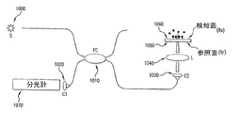
本発明によるファイバを用いた代表的な実施形態のSD−OCRシステムを図1に示す。例えば、図1に示すように、このシステムは、2×2ファイバカプラ等の干渉計(1010)を照射するように構成された広帯域光源(1000)を含み、この光束は回折限界のスポットの大きさで検知面上に焦点を結ぶことができる。検知面は、タンパク/DNAチップまたは微小流体素子の一部でよい。検知面1060(およびガラス1050)の界面から反射された光束は干渉計に再び結合して検出部にて干渉信号を生成させることができる。分光計(1070)のおける干渉に関する信号は次式で表すことができる。
例えば、代表的な分子吸収検出を実施するために、検知面における代表的なプローブ分子を既知の手順(Biacore AB社の1998年「BIACORE Getting Started」参照)によって固定またはパターン化することができる。これを実施形態するための方法の一つとして、センサ面をプローブ分子の高濃度溶液に数時間の間浸漬し、次にそれを燐酸バッファ生理食塩水(PBS)で洗浄することがあげられる。プローブ分子アレーのパターン化については、タンパク質を含んだポリジメチルシロキサン(PDMS)スタンプが、この表面に接触させられ物理吸収を行わせる、微小接触印刷技術を採用することによってなしうる(A.Bernardらの「Microcontact printing of proteins」Advanced Materials,2000,Vol.12,pp.1067−1070参照)。センサ面がプローブ分子で活性化された後、これらの図では、図1の代表的なシステムを用いた分子間相互作用の代表的な測定を説明する図2a〜2cに示すように被検体を検知面に導入してもよい。例えば、プローブ分子(2020)は検知面(2010)に固定することができ、目的の分子(2030)を導入できる。被検体がプローブ分子と作用し結合すると、センサ面の厚さが変化し、結合した分子の層からの反射は、測定中の干渉信号内で位相変化を起こす。換言すると、これらの分子がプローブ分子と結合すると、実時間で位相変化を検出可能できる。この代表的な変化を使用して、被検体のプローブ分子に対する親和性、およびこの相互作用に関する運動性を研究する。 For example, to perform representative molecular absorption detection, representative probe molecules on the sensing surface can be immobilized or patterned by known procedures (see Biacore AB, 1998, “BIACORE Getting Started”). One way to implement this is to immerse the sensor surface in a high concentration solution of probe molecules for several hours and then wash it with phosphate buffered saline (PBS). For patterning of probe molecule arrays, a polydimethylsiloxane (PDMS) stamp containing protein can be brought into contact with this surface to effect physical absorption (A. Bernard et al. "Microcontact printing of proteins", Advanced Materials, 2000, Vol. 12, pp. 1067-1070). After the sensor surface has been activated with probe molecules, these figures illustrate the subject as shown in FIGS. 2a-2c which illustrate representative measurements of intermolecular interactions using the representative system of FIG. You may introduce | transduce into a detection surface. For example, the probe molecule (2020) can be immobilized on the detection surface (2010), and the target molecule (2030) can be introduced. When the analyte acts on and binds to the probe molecule, the thickness of the sensor surface changes, and reflection from the layer of the bound molecule causes a phase change in the interference signal being measured. In other words, when these molecules bind to the probe molecule, the phase change can be detected in real time. This representative change is used to study the affinity of the analyte for the probe molecule and the motility associated with this interaction.
本発明の代表的な実施形態のシステム、装置および方法は、分子間相互作用のSD−OCR深さ分解測定を実施可能なSD−OCR装置の他の代表的な実施形態を例示する、図3に示す分子間相互作用の深さ分解検出も実行可能である。図3に示すように、ミラー(M:3080)を参照経路に設置してよく、分光計(3090)が参照ミラー(M:3080)からの反射と、分子が結合したガラススライド(3050、3060)からの反射との間の干渉のパワースペクトルを測定可能である。特に、この代表的な図3の装置は、さらに、広帯域光源(S:3000)、2×2ファイバカプラ(FC:3010)、コリメータ(C1:3020、C2:3030、C3:3070)、集束レンズ(L:3040)、分子が結合したガラススライド(3050、3060)および分光計(3090)を含んでよい。例えば、固定ミラーからの反射光束と多層素子の界面からの光束との間の干渉が測定される。 The system, apparatus and method of an exemplary embodiment of the present invention illustrate another exemplary embodiment of an SD-OCR apparatus capable of performing SD-OCR depth resolved measurements of intermolecular interactions, FIG. It is also possible to perform depth-resolved detection of intermolecular interactions shown in. As shown in FIG. 3, a mirror (M: 3080) may be placed in the reference path, and the spectrometer (3090) reflects from the reference mirror (M: 3080) and glass slides (3050, 3060) with molecules attached. The power spectrum of interference between reflections from In particular, this representative apparatus of FIG. 3 further includes a broadband light source (S: 3000), a 2 × 2 fiber coupler (FC: 3010), a collimator (C1: 3020, C2: 3030, C3: 3070), a focusing lens. (L: 3040), molecularly bound glass slides (3050, 3060) and spectrometer (3090). For example, the interference between the reflected light beam from the fixed mirror and the light beam from the interface of the multilayer element is measured.
図4は、本発明の代表的な実施形態による代表的な運用測定と、これに関連しこの出力を例示するグラフであり、図1および/または図3のSD−OCR生物学的検知装置および/または国際特許出願第PCT/US03/02349号に記載された装置を用いて、深さ分解情報を、例えば、ほとんどまたは全ての界面にて同時に測定するものである。例えば、電磁放射または光が1つまたは複数のレンズL(4000)を介して投射され、この図に示す分子が結合したセンサ面(4010、4020)が異なる分子によって活性化されうる。これらの表面に基づく代表的な深さ分解測定(4010、4020)は、固定された分子A、Bに対する目的分子の親和性が異なることを示しうる。強度情報を用いて、図3に示すそれぞれのセンサ面(3050、3060)を特定し、それぞれのセンサ面の位相を実時間で観測して、例えば、図4に示すように、異なる(プローブ)分子に対して同じまたは同様な被検体の動態を解析することが可能である。 FIG. 4 is a graph illustrating exemplary operational measurements and associated output in accordance with an exemplary embodiment of the present invention, the SD-OCR biological sensing device of FIGS. 1 and / or 3 and Using the apparatus described in International Patent Application No. PCT / US03 / 02349, depth resolution information is measured simultaneously at, for example, most or all interfaces. For example, electromagnetic radiation or light can be projected through one or more lenses L (4000) and the sensor surfaces (4010, 4020) to which the molecules shown in this figure are bound can be activated by different molecules. Representative depth-resolved measurements based on these surfaces (4010, 4020) may indicate that the target molecules have different affinities for immobilized molecules A, B. Using the intensity information, the respective sensor surfaces (3050, 3060) shown in FIG. 3 are specified, and the phases of the respective sensor surfaces are observed in real time. For example, as shown in FIG. It is possible to analyze the kinetics of the same or similar analyte with respect to the molecule.
図5の略図およびグラフに示すように、分子結合の高速多チャンネル検出の代表的な実施形態がプローブ分子のマイクロアレーを介して可能である。ガルバノメータ走査ミラー(GM:5000)、集束レンズ(L:5010)、および多分子が結合したガラススライド(5020)を例示する図5に示すように、スライド(5020)のセンサ面は、種々のプローブの小さな特徴(1〜10□m)でパターン化可能であり、その後に、空いている表面を不活性なタンパク質で飽和させる。目的の分子すなわち被検体が導入され、探査光束が検知面を渡って走査し、プローブ(すなわち活性化)部位のそれぞれにおける分子間相互作用を実時間で観測し測定する。非特異的なタンパク質・タンパク質結合(交差反応(cross reactivity))が、センサ面全体で一般的であるため、これは、センサ面全体を検査することにより、およびプローブ(すなわち活性化)領域における変化を非活性化領域のそれと比べることによって、解消可能である。 As shown in the schematic and graph of FIG. 5, an exemplary embodiment of fast multi-channel detection of molecular binding is possible via a microarray of probe molecules. As shown in FIG. 5, which illustrates a glass slide (5020) with a galvanometer scanning mirror (GM: 5000), a focusing lens (L: 5010), and a polymolecule, the sensor surface of the slide (5020) can be a variety of probes. Can be patterned with small features (1-10 □ m), after which the vacant surface is saturated with inert protein. The target molecule, that is, the analyte is introduced, and the probe light beam scans across the detection surface, and the intermolecular interaction at each of the probe (ie, activation) sites is observed and measured in real time. Since non-specific protein-protein binding (cross reactivity) is common across the sensor surface, this can be done by examining the entire sensor surface and changes in the probe (ie, activation) region. Can be resolved by comparing it with that of the non-activated region.
検知面上の分子吸収の検出に加え、本発明によるシステム、装置および方法の代表的な実施形態は、流体流路中の自由な分子の量(すなわち濃度)の測定のためにも使用可能である。例えば、溶液中に自由な分子の存在は流路の有効屈折率を変化させる可能性があり、流路の上面および底面からの反射光束間の干渉における位相を変化させることがある。
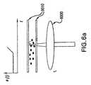
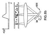
図6aおよび6bは、このような概念の代表的な2つの図で運用例示を示しているが、少なくとも1つの集束レンズ(L:6000)、微小流体素子(6010)、およびガルバノメータ光束走査器(GM:6030)を含む。図6aでは、流体流路の上壁と底壁との間の干渉における位相が、1つまたは複数の特定の位置で時間の関数として測定または観測され、分子を流路に導入すると測定位相が増加する。適切な校正を通じて、本発明の代表的な実施形態を用いて溶液の濃度レベルを定量することが可能である。図6bは、どのように2つの異なる分子が流体流路中を拡散するかを表す運用の略図を示す。図示するように、探査光束は流体流路に渡って走査し、分子が拡散する際に空間位相分布を測定する。分子が流路中に、例えば、微小流体素子(6010)の表面と表面の間に流入する際に、位相変化が引き起こされることがあり、分子濃度の変化を示すことがある。拡散測定では、探査光束は流路に渡って走査し、これらの分子の拡散によって起こる空間位相分布を測定する。この測定は有用であり、与えられた環境でラベルのない種の拡散速度および結合親和性を定量することが可能である。
添附データIn addition to detecting molecular absorption on the sensing surface, exemplary embodiments of the systems, devices and methods according to the present invention can also be used to measure the amount (ie concentration) of free molecules in a fluid flow path. is there. For example, the presence of free molecules in the solution can change the effective refractive index of the flow path and can change the phase in the interference between reflected light beams from the top and bottom surfaces of the flow path.
FIGS. 6a and 6b show operational illustrations in two representative views of such a concept, but at least one focusing lens (L: 6000), microfluidic device (6010), and galvanometer beam scanner ( GM: 6030). In FIG. 6a, the phase in the interference between the top and bottom walls of the fluid flow path is measured or observed as a function of time at one or more specific locations, and when a molecule is introduced into the flow path, the measured phase is To increase. Through appropriate calibration, it is possible to quantify the concentration level of a solution using exemplary embodiments of the present invention. FIG. 6b shows a schematic diagram of the operation showing how two different molecules diffuse in the fluid flow path. As shown, the probe beam scans across the fluid flow path and measures the spatial phase distribution as the molecules diffuse. When molecules flow into the channel, for example, between the surfaces of the microfluidic device (6010), a phase change may be caused, which may indicate a change in molecular concentration. In diffusion measurement, the probe beam is scanned across the flow path and the spatial phase distribution caused by the diffusion of these molecules is measured. This measurement is useful and it is possible to quantify the diffusion rate and binding affinity of unlabeled species in a given environment.
Attached data
I.ビオチンとストレプトアビジンの相互作用の測定
本発明の代表的な実施形態の実施の予備的な実証として、図7のようにセンサ面におけるビオチンとストレプトアビジンとの間の相互作用を測定したが、この図に本発明による代表的なSD−OCR生物学的検知装置によって測定された代表的なサブシクエントbBSAストレプトアビジン結合のグラフ7010を示す。微小流体素子の内部流路はビオチン化したウシ血清アルブミン(bBSA)によって活性化され、サブシクエントbBSAストレプトアビジン結合を検出するいくつかの実験が行われた。当初は、PBS溶液の導入で検知面における厚さは変化しなかったが、ストレプトアビジン溶液(1μM)が代表的な素子の中に注入された後に、固定されたbBSA層へのストレプトアビジンの結合による顕著な変化が観察された。図7に示すように、この厚さは、bBSAの全ての結合部位がストレプトアビジンによって占有された後に一定を保った。続くPBS溶液の導入では、測定厚さは変化しなかった。しかし、bBSA溶液を再度流入させた際に(3μM)、厚さの一層の増加が観察されたが、これは、bBSAストレプトアビジンの多層形成によって例示されるように、ストレプトアビジンの注入が流路中でbBSAに結合する能力を再生させたためであろう。続くバッファ溶液の導入で信号は変化しなかったが、bBSA溶液に戻した際には、厚さの一層の増加が観察された。I. Measurement of the interaction between biotin and streptavidin As a preliminary demonstration of the implementation of the exemplary embodiment of the present invention, the interaction between biotin and streptavidin on the sensor surface was measured as shown in FIG. Shown in the figure is a
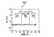
低濃度のストレプトアビジン溶液(250nM)を用いた管理用の実験も行われたが、これを図8aおよび8bに示す。例えば、図8aは、代表的な管理用のbBSAストレプトアビジン結合測定の代表的な結果を与えるグラフ8010を示し、bBSA官能化センサ面における厚さの増加を例示している。図8bは、代表的な管理用のbBSAストレプトアビジン結合測定の代表的な結果のグラフ8020を示し、非官能化表面における厚さの増加が観測されなかったことを例示している。これらの図に示すように、微小流体素子の流路はbBSAで官能化されており、ストレプトアビジンが流路中に導入された。先の測定と比べるとより遅い速度でのストレプトアビジンの結合による、厚さの増加が観察された。しかし、非官能化検知面の場合には、厚さは図8bに示すように変化せず、これはストレプトアビジンのビオチンに対する特異結合性質を示すものである。 A control experiment using a low concentration streptavidin solution (250 nM) was also performed and is shown in FIGS. 8a and 8b. For example, FIG. 8a shows a
II.SiO2エッチングの検出
図11に本発明による方法の代表的な実施形態の流れ図を示す。例えば、時間とともに変化する波長、および/または10nmより大きなスペクトル幅を有する特定の放射が光源装置によって提供する(ステップ110)。具体的には、ステップ120に示すように、第1の電磁放射を試料に提供し、第2の電磁放射が参照体に提供してもよい(両方とも特定の放射の一部である)。次にステップ130で、第3の電磁放射(第1の電磁放射に関連づけられる)と第4の電磁放射(第2の電磁放射に関連づけられる)との間の干渉を検出する。さらに、干渉に基づき試料の少なくとも一部の厚さの変化をステップ140で決定できる。II. Detection of SiO2 Etch FIG. 11 shows a flowchart of an exemplary embodiment of the method according to the present invention. For example, a specific radiation having a wavelength that varies with time and / or a spectral width greater than 10 nm is provided by the light source device (step 110). Specifically, as shown in
本発明による方法の代表的な実施形態を用いて、希釈されたフッ酸(HF)溶液によってエッチングされた二酸化珪素分子(SiO2、MW:約60Da)の数を測定が可能である(Handbook of Chemistry and Physics,86 ed.,2005:CRC Press,p.2544参照)。SiO2は小分子の代表であり、その表面密度はよく知られている。この例では、カバースリップ底培養ディシュ(Mattek,Ashland,MA)が脱イオン水で満たされ、HF溶液がディッシュ中に注入され所望の濃度にされた。カバースリップ表面での探査光束は約5μmの直径を有し、有効厚さ変化が時間の関数として観測された。図9aは本発明による、容積にて約0.07%の特定のHF濃度におけるカバースリップ厚さの代表的な変化を例示するグラフを示す。図9aのこのグラフでは、測定されたエッチング速度は約51nm/minであった。カバースリップ底培養ディシュは脱イオン水で満たされ、HF溶液がディッシュ中に注入され所望の濃度(7x10−5〜0.7%)にされた。二酸化珪素分子のエッチング速度の変化も、図9bに示すようにHF濃度の変化として測定され、この図に、例えばHF濃度が0.05%より大きい場合に、本発明による種々のHF濃度でのエッチング速度の代表的な大きな変化のグラフを例示する。Using an exemplary embodiment of the method according to the invention, it is possible to determine the number of silicon dioxide molecules (SiO2 , MW: approx. 60 Da) etched by a diluted hydrofluoric acid (HF) solution (Handbook of Chemistry and Physics, 86 ed., 2005: CRC Press, p. 2544). SiO2 is a representative small molecule and its surface density is well known. In this example, a coverslip bottom culture dish (Mattek, Ashland, Mass.) Was filled with deionized water and an HF solution was injected into the dish to the desired concentration. The probe beam at the cover slip surface had a diameter of about 5 μm, and an effective thickness change was observed as a function of time. FIG. 9a shows a graph illustrating a typical change in cover slip thickness at a specific HF concentration of about 0.07% by volume according to the present invention. In this graph of FIG. 9a, the measured etch rate was about 51 nm / min. The coverslip bottom culture dish was filled with deionized water and the HF solution was poured into the dish to the desired concentration (7 × 10⁻⁵ to 0.7%). The change in the etching rate of silicon dioxide molecules is also measured as the change in HF concentration as shown in FIG. 9b, which shows, for example, when the HF concentration is greater than 0.05% at various HF concentrations according to the present invention. 2 illustrates a graph of a representative large change in etch rate.
III.光合成タンパク質層の画像
ホウレンソウから抽出された光合成タンパク質は微細スタンプ接触印刷技術(A.Bernardらの「Microcontact printing of proteins」Advanced Materials,2000,Vol.12,pp.1067−1070参照)を用いてカバースリップ上にパターン化され、タンパク質のパターンが、カバースリップの上面および底面からの反射間の干渉における位相測定として、本発明の代表的なシステム、装置、および方法によって画像化された。図10に、本発明による装置および方法を用いて表面に生成された光合成タンパク質層の分布画像のグラフ10000を示す。カバースリップに渡り、カバースリップの上面および底面間の干渉における位相測定によって厚さの分布が得られた。光合成タンパク質層が微小スタンプ接触印刷技術によってパターン化された。この結果は、極めて薄い有機物層または薄膜の画像化に対して本発明の潜在能力を実証するものである。III. Image of photosynthetic protein layer Photosynthetic protein extracted from spinach is covered using a fine stamp contact printing technique (see A. Bernard et al., “Microcontact printing of proteins”, Advanced Materials, 2000, Vol. 12, pp. 1067-1070). Patterned on the slip, the protein pattern was imaged by the exemplary system, apparatus, and method of the present invention as a phase measurement in the interference between reflections from the top and bottom surfaces of the coverslip. FIG. 10 shows a
本発明によるシステム、装置、および方法の代表的な実施形態には、化学的および生物学的な種の検出の実施においていくかの態様がある。例えば、これらの代表的な実施形態は、次のものを提供する。
i.ラベルを用いない検出であり、例えば分子認識が、蛍光性および放射性のラベル等の試料分離を必要とせずに達成可能である。
ii.検知範囲は、おおよそ回折限界の大きさ(約1ミクロン)程に小さいことが可能で、著しく少量の分子で検出が達成可能である。
iii.検出範囲の大きさが小さいため、使い捨ての2次元アレー上の複数の活性化プローブ部位の観測が同時に可能である。
iv.代表的な測定システムおよび装置はマイクロアレーや微小流体素子から完全に切り離し可能であり、このため、どのような環境にも配備可能であり、センサ面の再生を使用しないでよい。
v.多層深さ分解分子検出が実施可能である。
vi.測定はマイクロ秒の時間分解で達成可能であり、代表的な実施形態は、DNAの変性等の速い動的な過程に応用可能である。
vii.代表的な実施形態は、また、微小流体素子中の自由な分子の濃度および拡散の測定に用いることが可能である。Exemplary embodiments of systems, apparatus, and methods according to the present invention have several aspects in performing chemical and biological species detection. For example, these exemplary embodiments provide the following:
i. Detection without labeling, for example, molecular recognition can be achieved without the need for sample separation such as fluorescent and radioactive labels.
ii. The detection range can be as small as about the diffraction limit (about 1 micron), and detection can be achieved with a significantly smaller amount of molecules.
iii. Since the size of the detection range is small, it is possible to simultaneously observe a plurality of activated probe sites on a disposable two-dimensional array.
iv. Exemplary measurement systems and devices are completely separable from microarrays and microfluidic devices, so that they can be deployed in any environment and sensor surface regeneration may not be used.
v. Multilayer depth-resolved molecular detection can be performed.
vi. Measurement can be achieved with microsecond time resolution, and exemplary embodiments are applicable to fast dynamic processes such as DNA denaturation.
vii. Exemplary embodiments can also be used to measure the concentration and diffusion of free molecules in a microfluidic device.
前述のものは、単に、本発明の原理を例示するものである。本明細書の教示を考慮して、説明した実施形態にさまざまな修正や変更を行うことは、当業者にとって自明であろう。実際に、本発明の代表的な実施形態による装置、システム、および方法は、どのようなOCTシステム、OFDIシステム、SD−OCTシステム、または他の画像化システム、例えば、2004年9月8日出願の国際特許出願第PCT/US2004/029148号、2005年11月2日出願の米国特許出願第11/266,779号、および2004年7月9日出願の米国特許出願第10/501,276号に記載されているものに対しても使用可能であり、これらの開示の全てを本明細書の一部として援用する。当業者には、本明細書に明確に図示または説明されていなくても、本発明の原理を具現化するシステム、装置、および方法を多数案出することが可能であり、従って、これらも本発明の趣旨と範囲内であることが理解されるであろう。さらに、上述の明細書に前記の先行技術の知識が明示的に援用されていない範囲においても、その全体を明示的に本明細書に援用する。本明細書で引用した上述の全ての文献は、その全体を本明細書の一部として援用する。 The foregoing merely illustrates the principles of the invention. It will be apparent to those skilled in the art that various modifications and variations can be made to the described embodiments in light of the teachings herein. Indeed, the apparatus, system, and method according to exemplary embodiments of the present invention can be applied to any OCT system, OFDI system, SD-OCT system, or other imaging system, eg, filed Sep. 8, 2004. International Patent Application No. PCT / US2004 / 029148, US Patent Application No. 11 / 266,779 filed November 2, 2005, and US Patent Application No. 10 / 501,276 filed July 9, 2004. And all of these disclosures are incorporated herein by reference. Those skilled in the art can devise numerous systems, devices, and methods that embody the principles of the present invention, even if not explicitly illustrated or described herein, and thus these are It will be understood that it is within the spirit and scope of the invention. Furthermore, the entire contents of the above-mentioned specification are expressly incorporated in the present specification even in a range where the above-mentioned prior art knowledge is not explicitly incorporated. All of the above references cited herein are hereby incorporated by reference in their entirety.
Claims (20)
Translated fromJapanese前記少なくとも1つの第1の電磁放射に関連づけられた少なくとも1つの第3の電磁放射と、前記少なくとも1つの第2の電磁放射に関連づけられた少なくとも1つの第4の電磁放射との間の干渉を検出するように構成された、少なくとも1つの第2の装置と、
前記干渉に基づいて前記少なくとも1つの試料の少なくとも一部の厚さの変化を決定するように構成された、少なくとも1つの第3の装置と、を含むシステムであって、
前記特定の放射が、
i.前記少なくとも1つの第1の装置によって提供された時間とともに変化する波長、または
ii.10nmよりも大きいスペクトル幅、の少なくとも一方を有することを特徴とするシステム。At least one configured to provide specific radiation including at least one first electromagnetic radiation directed at at least one sample and at least one second electromagnetic radiation directed at the reference body A first device;
Interference between at least one third electromagnetic radiation associated with the at least one first electromagnetic radiation and at least one fourth electromagnetic radiation associated with the at least one second electromagnetic radiation; At least one second device configured to detect;
A system comprising: at least one third device configured to determine a change in thickness of at least a portion of the at least one sample based on the interference;
The specific radiation is
i. A time varying wavelength provided by the at least one first device, or ii. A system having at least one of a spectral width greater than 10 nm.
i.前記干渉を複素数形式の第1のデータに変換し、
ii.前記第1のデータに関連づけられた絶対値を決定して第2のデータを生成し、
iii.前記少なくとも一部の特定の位置を前記第2のデータの関数として識別し、
iv.前記第1のデータに関連づけられた位相を決定して第3のデータを生成し、
v.前記厚さの前記変化を前記第3のデータに関連づけることによって、厚さを決定する、請求項1記載のシステム。The at least one third device comprises:
i. Converting the interference into first data in a complex number format;
ii. Determining an absolute value associated with the first data to generate second data;
iii. Identifying the particular location of the at least part as a function of the second data;
iv. Determining a phase associated with the first data to generate third data;
v. The system of claim 1, wherein the thickness is determined by associating the change in the thickness with the third data.
前記少なくとも1つの第1の電磁放射に関連づけられた少なくとも1つの第3の電磁放射と、前記少なくとも1つの第2の電磁放射に関連づけられた少なくとも1つの第4の電磁放射との間の干渉を検出するステップと、
前記干渉に基づいて前記少なくとも1つの試料の少なくとも一部の厚さの変化を決定するステップと、を含む方法であって、
前記特定の放射が、
i.時間とともに変化する波長、または
ii.10nmよりも大きいスペクトル幅、の少なくとも一方を有することを特徴とする方法。Providing specific radiation comprising at least one first electromagnetic radiation directed at at least one sample and at least one second electromagnetic radiation directed at a reference body;
Interference between at least one third electromagnetic radiation associated with the at least one first electromagnetic radiation and at least one fourth electromagnetic radiation associated with the at least one second electromagnetic radiation; Detecting step;
Determining a change in thickness of at least a portion of the at least one sample based on the interference, comprising:
The specific radiation is
i. A wavelength that changes over time, or ii. A method having at least one of a spectral width greater than 10 nm.
Applications Claiming Priority (2)
| Application Number | Priority Date | Filing Date | Title |
|---|---|---|---|
| US68094705P | 2005-05-13 | 2005-05-13 | |
| PCT/US2006/018865WO2006124860A1 (en) | 2005-05-13 | 2006-05-15 | Arrangements, systems and methods capable of providing spectral-domain optical coherence reflectometry for a sensitive detection of chemical and biological sample |
Publications (1)
| Publication Number | Publication Date |
|---|---|
| JP2008541096Atrue JP2008541096A (en) | 2008-11-20 |
Family
ID=36808984
Family Applications (1)
| Application Number | Title | Priority Date | Filing Date |
|---|---|---|---|
| JP2008511472AWithdrawnJP2008541096A (en) | 2005-05-13 | 2006-05-15 | Apparatus, system, and method capable of performing spectral domain optical coherence reflectometry for sensitive detection of chemical and biological samples |
Country Status (4)
| Country | Link |
|---|---|
| US (1) | US20070009935A1 (en) |
| EP (1) | EP1886121A1 (en) |
| JP (1) | JP2008541096A (en) |
| WO (1) | WO2006124860A1 (en) |
Cited By (2)
| Publication number | Priority date | Publication date | Assignee | Title |
|---|---|---|---|---|
| JP2018048954A (en)* | 2016-09-23 | 2018-03-29 | 株式会社Screenホールディングス | Imaging apparatus and imaging method |
| WO2018123377A1 (en)* | 2016-12-26 | 2018-07-05 | 株式会社Screenホールディングス | Imaging device and imaging method |
Families Citing this family (78)
| Publication number | Priority date | Publication date | Assignee | Title |
|---|---|---|---|---|
| US7231243B2 (en) | 2000-10-30 | 2007-06-12 | The General Hospital Corporation | Optical methods for tissue analysis |
| US9295391B1 (en) | 2000-11-10 | 2016-03-29 | The General Hospital Corporation | Spectrally encoded miniature endoscopic imaging probe |
| AT503309B1 (en) | 2001-05-01 | 2011-08-15 | Gen Hospital Corp | DEVICE FOR DETERMINING ATHEROSCLEROTIC BEARING BY MEASURING OPTICAL TISSUE PROPERTIES |
| US7355716B2 (en) | 2002-01-24 | 2008-04-08 | The General Hospital Corporation | Apparatus and method for ranging and noise reduction of low coherence interferometry LCI and optical coherence tomography OCT signals by parallel detection of spectral bands |
| US8054468B2 (en) | 2003-01-24 | 2011-11-08 | The General Hospital Corporation | Apparatus and method for ranging and noise reduction of low coherence interferometry LCI and optical coherence tomography OCT signals by parallel detection of spectral bands |
| EP2436307B1 (en) | 2003-03-31 | 2015-10-21 | The General Hospital Corporation | Speckle reduction in optical coherence tomography by path length encoded angular compounding |
| KR101386971B1 (en) | 2003-06-06 | 2014-04-18 | 더 제너럴 하스피탈 코포레이션 | Process and apparatus for a wavelength tunning source |
| EP2280256B1 (en) | 2003-10-27 | 2016-11-16 | The General Hospital Corporation | Method and apparatus for performing optical imaging using frequency-domain interferometry |
| KR101239250B1 (en) | 2004-05-29 | 2013-03-05 | 더 제너럴 하스피탈 코포레이션 | Process, system and software arrangement for a chromatic dispersion compensation using reflective layers in optical coherence tomography (oct) imaging |
| AU2005270037B2 (en) | 2004-07-02 | 2012-02-09 | The General Hospital Corporation | Endoscopic imaging probe comprising dual clad fibre |
| EP1782020B1 (en) | 2004-08-06 | 2012-10-03 | The General Hospital Corporation | Process, system and software arrangement for determining at least one location in a sample using an optical coherence tomography |
| WO2006024014A2 (en) | 2004-08-24 | 2006-03-02 | The General Hospital Corporation | Process, system and software arrangement for measuring a mechanical strain and elastic properties of a sample |
| EP2272421A1 (en) | 2004-08-24 | 2011-01-12 | The General Hospital Corporation | Method and apparatus for imaging of vessel segments |
| US7365859B2 (en) | 2004-09-10 | 2008-04-29 | The General Hospital Corporation | System and method for optical coherence imaging |
| KR101257100B1 (en) | 2004-09-29 | 2013-04-22 | 더 제너럴 하스피탈 코포레이션 | System and Method for Optical Coherence Imaging |
| WO2006058049A1 (en) | 2004-11-24 | 2006-06-01 | The General Hospital Corporation | Common-path interferometer for endoscopic oct |
| WO2006058346A1 (en) | 2004-11-29 | 2006-06-01 | The General Hospital Corporation | Arrangements, devices, endoscopes, catheters and methods for performing optical imaging by simultaneously illuminating and detecting multiple points on a sample |
| ES2337497T3 (en) | 2005-04-28 | 2010-04-26 | The General Hospital Corporation | EVALUATION OF CHARACTERISTICS OF THE IMAGE OF AN ANATOMICAL STRUCTURE IN IMAGES OF TOMOGRAPHY OF OPTICAL COHERENCE. |
| US9060689B2 (en) | 2005-06-01 | 2015-06-23 | The General Hospital Corporation | Apparatus, method and system for performing phase-resolved optical frequency domain imaging |
| EP2267404B1 (en) | 2005-08-09 | 2016-10-05 | The General Hospital Corporation | Apparatus and method for performing polarization-based quadrature demodulation in optical coherence tomography |
| US7843572B2 (en) | 2005-09-29 | 2010-11-30 | The General Hospital Corporation | Method and apparatus for optical imaging via spectral encoding |
| US7889348B2 (en) | 2005-10-14 | 2011-02-15 | The General Hospital Corporation | Arrangements and methods for facilitating photoluminescence imaging |
| EP1971848B1 (en) | 2006-01-10 | 2019-12-04 | The General Hospital Corporation | Systems and methods for generating data based on one or more spectrally-encoded endoscopy techniques |
| DK1973466T3 (en) | 2006-01-19 | 2021-02-01 | Massachusetts Gen Hospital | BALLOON IMAGING CATHETER |
| US8145018B2 (en) | 2006-01-19 | 2012-03-27 | The General Hospital Corporation | Apparatus for obtaining information for a structure using spectrally-encoded endoscopy techniques and methods for producing one or more optical arrangements |
| WO2007149602A2 (en) | 2006-02-01 | 2007-12-27 | The General Hospital Corporation | Methods and systems for providing electromagnetic radiation to at least one portion of a sample using conformal laser therapy procedures |
| JP5680829B2 (en) | 2006-02-01 | 2015-03-04 | ザ ジェネラル ホスピタル コーポレイション | A device that irradiates a sample with multiple electromagnetic radiations |
| US9777053B2 (en) | 2006-02-08 | 2017-10-03 | The General Hospital Corporation | Methods, arrangements and systems for obtaining information associated with an anatomical sample using optical microscopy |
| EP2982929A1 (en) | 2006-02-24 | 2016-02-10 | The General Hospital Corporation | Methods and systems for performing angle-resolved fourier-domain optical coherence tomography |
| WO2007133961A2 (en) | 2006-05-10 | 2007-11-22 | The General Hospital Corporation | Processes, arrangements and systems for providing frequency domain imaging of a sample |
| US7782464B2 (en) | 2006-05-12 | 2010-08-24 | The General Hospital Corporation | Processes, arrangements and systems for providing a fiber layer thickness map based on optical coherence tomography images |
| US7920271B2 (en) | 2006-08-25 | 2011-04-05 | The General Hospital Corporation | Apparatus and methods for enhancing optical coherence tomography imaging using volumetric filtering techniques |
| US8838213B2 (en) | 2006-10-19 | 2014-09-16 | The General Hospital Corporation | Apparatus and method for obtaining and providing imaging information associated with at least one portion of a sample, and effecting such portion(s) |
| EP2104968A1 (en) | 2007-01-19 | 2009-09-30 | The General Hospital Corporation | Rotating disk reflection for fast wavelength scanning of dispersed broadband light |
| US9176319B2 (en) | 2007-03-23 | 2015-11-03 | The General Hospital Corporation | Methods, arrangements and apparatus for utilizing a wavelength-swept laser using angular scanning and dispersion procedures |
| US10534129B2 (en) | 2007-03-30 | 2020-01-14 | The General Hospital Corporation | System and method providing intracoronary laser speckle imaging for the detection of vulnerable plaque |
| US8045177B2 (en) | 2007-04-17 | 2011-10-25 | The General Hospital Corporation | Apparatus and methods for measuring vibrations using spectrally-encoded endoscopy |
| US9375158B2 (en) | 2007-07-31 | 2016-06-28 | The General Hospital Corporation | Systems and methods for providing beam scan patterns for high speed doppler optical frequency domain imaging |
| WO2009029843A1 (en) | 2007-08-31 | 2009-03-05 | The General Hospital Corporation | System and method for self-interference fluoresence microscopy, and computer-accessible medium associated therewith |
| WO2009033064A2 (en)* | 2007-09-05 | 2009-03-12 | The General Hospital Corporation | Systems, methods and computer-accessible medium for providing spectral-domain optical coherence phase microscopy for cell and deep tissue imaging |
| US7933021B2 (en) | 2007-10-30 | 2011-04-26 | The General Hospital Corporation | System and method for cladding mode detection |
| US11123047B2 (en) | 2008-01-28 | 2021-09-21 | The General Hospital Corporation | Hybrid systems and methods for multi-modal acquisition of intravascular imaging data and counteracting the effects of signal absorption in blood |
| US7898656B2 (en) | 2008-04-30 | 2011-03-01 | The General Hospital Corporation | Apparatus and method for cross axis parallel spectroscopy |
| EP2274572A4 (en) | 2008-05-07 | 2013-08-28 | Gen Hospital Corp | SYSTEM, METHOD AND COMPUTER MEDIUM FOR MONITORING THE MOVEMENT OF VESSELS DURING A THREE-DIMENSIONAL MICROSCOPY EXAMINATION OF CORONARY ARTERIES |
| US8861910B2 (en) | 2008-06-20 | 2014-10-14 | The General Hospital Corporation | Fused fiber optic coupler arrangement and method for use thereof |
| WO2010009136A2 (en) | 2008-07-14 | 2010-01-21 | The General Hospital Corporation | Apparatus and methods for color endoscopy |
| JP5731394B2 (en) | 2008-12-10 | 2015-06-10 | ザ ジェネラル ホスピタル コーポレイション | System, apparatus and method for extending imaging depth range of optical coherence tomography through optical subsampling |
| JP2012515576A (en) | 2009-01-20 | 2012-07-12 | ザ ジェネラル ホスピタル コーポレイション | Endoscopic biopsy device, system, and method |
| US8097864B2 (en) | 2009-01-26 | 2012-01-17 | The General Hospital Corporation | System, method and computer-accessible medium for providing wide-field superresolution microscopy |
| FR2942049B1 (en)* | 2009-02-12 | 2011-04-01 | Ecole Norm Superieure Lyon | HIGH RESOLUTION SURFACE PLASMON MICROSCOPE COMPRISING A HETERODYNE FIBER INTERFEROMETER |
| WO2010105197A2 (en) | 2009-03-12 | 2010-09-16 | The General Hospital Corporation | Non-contact optical system, computer-accessible medium and method for measuring at least one mechanical property of tissue using coherent speckle techniques(s) |
| JP5819823B2 (en) | 2009-07-14 | 2015-11-24 | ザ ジェネラル ホスピタル コーポレイション | Device for measuring the flow and pressure inside a blood vessel and method of operating the device |
| US20110122412A1 (en)* | 2009-11-23 | 2011-05-26 | General Electric Company | Devices and methods for optical detection |
| KR20130004326A (en) | 2010-03-05 | 2013-01-09 | 더 제너럴 하스피탈 코포레이션 | Systems, methods and computer-accessible medium which provide microscopic images of at least one anatomical structure at a particular resolution |
| US9069130B2 (en) | 2010-05-03 | 2015-06-30 | The General Hospital Corporation | Apparatus, method and system for generating optical radiation from biological gain media |
| EP2575597B1 (en) | 2010-05-25 | 2022-05-04 | The General Hospital Corporation | Apparatus for providing optical imaging of structures and compositions |
| EP2575598A2 (en) | 2010-05-25 | 2013-04-10 | The General Hospital Corporation | Apparatus, systems, methods and computer-accessible medium for spectral analysis of optical coherence tomography images |
| JP6066901B2 (en) | 2010-06-03 | 2017-01-25 | ザ ジェネラル ホスピタル コーポレイション | Method for apparatus and device for imaging structures in or in one or more luminal organs |
| WO2012058381A2 (en) | 2010-10-27 | 2012-05-03 | The General Hospital Corporation | Apparatus, systems and methods for measuring blood pressure within at least one vessel |
| US9330092B2 (en) | 2011-07-19 | 2016-05-03 | The General Hospital Corporation | Systems, methods, apparatus and computer-accessible-medium for providing polarization-mode dispersion compensation in optical coherence tomography |
| EP3835718B1 (en) | 2011-08-25 | 2023-07-26 | The General Hospital Corporation | Apparatus for providing micro-optical coherence tomography inside a respiratory system |
| CN103842799B (en)* | 2011-09-30 | 2017-09-08 | 通用电气公司 | Systems and methods for self-referencing detection and imaging of sample arrays |
| JP2015502562A (en) | 2011-10-18 | 2015-01-22 | ザ ジェネラル ホスピタル コーポレイション | Apparatus and method for generating and / or providing recirculating optical delay |
| WO2013148306A1 (en) | 2012-03-30 | 2013-10-03 | The General Hospital Corporation | Imaging system, method and distal attachment for multidirectional field of view endoscopy |
| JP2015517387A (en) | 2012-05-21 | 2015-06-22 | ザ ジェネラル ホスピタル コーポレイション | Apparatus, device and method for capsule microscopy |
| US9968261B2 (en) | 2013-01-28 | 2018-05-15 | The General Hospital Corporation | Apparatus and method for providing diffuse spectroscopy co-registered with optical frequency domain imaging |
| WO2014120791A1 (en) | 2013-01-29 | 2014-08-07 | The General Hospital Corporation | Apparatus, systems and methods for providing information regarding the aortic valve |
| US11179028B2 (en) | 2013-02-01 | 2021-11-23 | The General Hospital Corporation | Objective lens arrangement for confocal endomicroscopy |
| US10478072B2 (en) | 2013-03-15 | 2019-11-19 | The General Hospital Corporation | Methods and system for characterizing an object |
| EP2997354A4 (en) | 2013-05-13 | 2017-01-18 | The General Hospital Corporation | Detecting self-interefering fluorescence phase and amplitude |
| WO2015009932A1 (en) | 2013-07-19 | 2015-01-22 | The General Hospital Corporation | Imaging apparatus and method which utilizes multidirectional field of view endoscopy |
| EP3021735A4 (en) | 2013-07-19 | 2017-04-19 | The General Hospital Corporation | Determining eye motion by imaging retina. with feedback |
| WO2015013651A2 (en) | 2013-07-26 | 2015-01-29 | The General Hospital Corporation | System, apparatus and method utilizing optical dispersion for fourier-domain optical coherence tomography |
| WO2015105870A1 (en) | 2014-01-08 | 2015-07-16 | The General Hospital Corporation | Method and apparatus for microscopic imaging |
| US10736494B2 (en) | 2014-01-31 | 2020-08-11 | The General Hospital Corporation | System and method for facilitating manual and/or automatic volumetric imaging with real-time tension or force feedback using a tethered imaging device |
| WO2015153982A1 (en) | 2014-04-04 | 2015-10-08 | The General Hospital Corporation | Apparatus and method for controlling propagation and/or transmission of electromagnetic radiation in flexible waveguide(s) |
| US10912462B2 (en) | 2014-07-25 | 2021-02-09 | The General Hospital Corporation | Apparatus, devices and methods for in vivo imaging and diagnosis |
| CN105842257B (en)* | 2016-05-09 | 2019-01-11 | 南京理工大学 | A kind of the glass subsurface defect detection device and method of sub-micrometer scale |
Family Cites Families (99)
| Publication number | Priority date | Publication date | Assignee | Title |
|---|---|---|---|---|
| US38040A (en)* | 1863-03-31 | Improvement in treating phosphatic guanos | ||
| US273777A (en)* | 1883-03-13 | Purifying water | ||
| US86347A (en)* | 1869-02-02 | Improvement in the manufacture of tin-lined lead pipes | ||
| US188855A (en)* | 1877-03-27 | Improvement in can-jackets | ||
| US53673A (en)* | 1866-04-03 | Improved railway-frog | ||
| US174339A (en)* | 1876-02-29 | Improvement in stockings | ||
| US171691A (en)* | 1876-01-04 | Improvement in heating-stoves | ||
| US254474A (en)* | 1882-03-07 | Automatic discharging apparatus for bone-black kilns | ||
| US137669A (en)* | 1873-04-08 | Improvement in machines for cutting coal | ||
| US236700A (en)* | 1881-01-18 | Machine for cleaning cotton | ||
| US2339754A (en)* | 1941-03-04 | 1944-01-25 | Westinghouse Electric & Mfg Co | Supervisory apparatus |
| US3030816A (en)* | 1960-06-03 | 1962-04-24 | Specialties Dev Corp | Control device |
| US3082105A (en)* | 1960-09-29 | 1963-03-19 | Bethlehem Steel Corp | Chrome silica brick |
| US3120137A (en)* | 1961-01-03 | 1964-02-04 | Ingersoll Rand Canada | Apparatus for forming varying shaped bores in hollow members |
| US3872407A (en)* | 1972-09-01 | 1975-03-18 | Us Navy | Rapidly tunable laser |
| JPS584481Y2 (en)* | 1973-06-23 | 1983-01-26 | オリンパス光学工業株式会社 | Naishikiyoushiyahenkankogakkei |
| US4002650A (en)* | 1973-12-10 | 1977-01-11 | The Standard Oil Company (Ohio) | Preparation of maleic anhydride from n-butane |
| DE2601226C3 (en)* | 1976-01-14 | 1982-01-14 | Zahnradfabrik Friedrichshafen Ag, 7990 Friedrichshafen | Control device for the automotive control of the hydraulic variable displacement pump of a hydrostat |
| US4428643A (en)* | 1981-04-08 | 1984-01-31 | Xerox Corporation | Optical scanning system with wavelength shift correction |
| CH663466A5 (en)* | 1983-09-12 | 1987-12-15 | Battelle Memorial Institute | METHOD AND DEVICE FOR DETERMINING THE POSITION OF AN OBJECT IN RELATION TO A REFERENCE. |
| US4650327A (en)* | 1985-10-28 | 1987-03-17 | Oximetrix, Inc. | Optical catheter calibrating assembly |
| US5202931A (en)* | 1987-10-06 | 1993-04-13 | Cell Analysis Systems, Inc. | Methods and apparatus for the quantitation of nuclear protein |
| US4909631A (en)* | 1987-12-18 | 1990-03-20 | Tan Raul Y | Method for film thickness and refractive index determination |
| US4890901A (en)* | 1987-12-22 | 1990-01-02 | Hughes Aircraft Company | Color corrector for embedded prisms |
| US4892406A (en)* | 1988-01-11 | 1990-01-09 | United Technologies Corporation | Method of and arrangement for measuring vibrations |
| US5730731A (en)* | 1988-04-28 | 1998-03-24 | Thomas J. Fogarty | Pressure-based irrigation accumulator |
| US4998972A (en)* | 1988-04-28 | 1991-03-12 | Thomas J. Fogarty | Real time angioscopy imaging system |
| US4905169A (en)* | 1988-06-02 | 1990-02-27 | The United States Of America As Represented By The United States Department Of Energy | Method and apparatus for simultaneously measuring a plurality of spectral wavelengths present in electromagnetic radiation |
| DE3833602A1 (en)* | 1988-10-03 | 1990-02-15 | Krupp Gmbh | SPECTROMETER FOR SIMULTANEOUS INTENSITY MEASUREMENT IN DIFFERENT SPECTRAL AREAS |
| US5085496A (en)* | 1989-03-31 | 1992-02-04 | Sharp Kabushiki Kaisha | Optical element and optical pickup device comprising it |
| US4984888A (en)* | 1989-12-13 | 1991-01-15 | Imo Industries, Inc. | Two-dimensional spectrometer |
| US5197470A (en)* | 1990-07-16 | 1993-03-30 | Eastman Kodak Company | Near infrared diagnostic method and instrument |
| US5202745A (en)* | 1990-11-07 | 1993-04-13 | Hewlett-Packard Company | Polarization independent optical coherence-domain reflectometry |
| US5275594A (en)* | 1990-11-09 | 1994-01-04 | C. R. Bard, Inc. | Angioplasty system having means for identification of atherosclerotic plaque |
| JP3035336B2 (en)* | 1990-11-27 | 2000-04-24 | 興和株式会社 | Blood flow measurement device |
| US5293872A (en)* | 1991-04-03 | 1994-03-15 | Alfano Robert R | Method for distinguishing between calcified atherosclerotic tissue and fibrous atherosclerotic tissue or normal cardiovascular tissue using Raman spectroscopy |
| JP3479069B2 (en)* | 1991-04-29 | 2003-12-15 | マサチューセッツ・インステチュート・オブ・テクノロジー | Method and apparatus for optical imaging and measurement |
| DE4128744C1 (en)* | 1991-08-29 | 1993-04-22 | Siemens Ag, 8000 Muenchen, De | |
| US5486701A (en)* | 1992-06-16 | 1996-01-23 | Prometrix Corporation | Method and apparatus for measuring reflectance in two wavelength bands to enable determination of thin film thickness |
| US5716324A (en)* | 1992-08-25 | 1998-02-10 | Fuji Photo Film Co., Ltd. | Endoscope with surface and deep portion imaging systems |
| US5383467A (en)* | 1992-11-18 | 1995-01-24 | Spectrascience, Inc. | Guidewire catheter and apparatus for diagnostic imaging |
| ATE151615T1 (en)* | 1992-11-18 | 1997-05-15 | Spectrascience Inc | DIAGNOSTIC IMAGE DEVICE |
| JP3112595B2 (en)* | 1993-03-17 | 2000-11-27 | 安藤電気株式会社 | Optical fiber strain position measuring device using optical frequency shifter |
| DE4310209C2 (en)* | 1993-03-29 | 1996-05-30 | Bruker Medizintech | Optical stationary imaging in strongly scattering media |
| US5590660A (en)* | 1994-03-28 | 1997-01-07 | Xillix Technologies Corp. | Apparatus and method for imaging diseased tissue using integrated autofluorescence |
| TW275570B (en)* | 1994-05-05 | 1996-05-11 | Boehringer Mannheim Gmbh | |
| US5491524A (en)* | 1994-10-05 | 1996-02-13 | Carl Zeiss, Inc. | Optical coherence tomography corneal mapping apparatus |
| US6033721A (en)* | 1994-10-26 | 2000-03-07 | Revise, Inc. | Image-based three-axis positioner for laser direct write microchemical reaction |
| US5600486A (en)* | 1995-01-30 | 1997-02-04 | Lockheed Missiles And Space Company, Inc. | Color separation microlens |
| RU2100787C1 (en)* | 1995-03-01 | 1997-12-27 | Геликонов Валентин Михайлович | Fibre-optical interferometer and fiber-optical piezoelectric transducer |
| AU1130797A (en)* | 1995-08-24 | 1997-03-19 | Purdue Research Foundation | Fluorescence lifetime-based imaging and spectroscopy in tissues and other random media |
| US6016197A (en)* | 1995-08-25 | 2000-01-18 | Ceramoptec Industries Inc. | Compact, all-optical spectrum analyzer for chemical and biological fiber optic sensors |
| US6763261B2 (en)* | 1995-09-20 | 2004-07-13 | Board Of Regents, The University Of Texas System | Method and apparatus for detecting vulnerable atherosclerotic plaque |
| US5719399A (en)* | 1995-12-18 | 1998-02-17 | The Research Foundation Of City College Of New York | Imaging and characterization of tissue based upon the preservation of polarized light transmitted therethrough |
| ATA84696A (en)* | 1996-05-14 | 1998-03-15 | Adolf Friedrich Dr Fercher | METHOD AND ARRANGEMENTS FOR INCREASING CONTRAST IN OPTICAL COHERENCE TOMOGRAPHY |
| US6020963A (en)* | 1996-06-04 | 2000-02-01 | Northeastern University | Optical quadrature Interferometer |
| US6044288A (en)* | 1996-11-08 | 2000-03-28 | Imaging Diagnostics Systems, Inc. | Apparatus and method for determining the perimeter of the surface of an object being scanned |
| US6517532B1 (en)* | 1997-05-15 | 2003-02-11 | Palomar Medical Technologies, Inc. | Light energy delivery head |
| US5871449A (en)* | 1996-12-27 | 1999-02-16 | Brown; David Lloyd | Device and method for locating inflamed plaque in an artery |
| US20080004922A1 (en)* | 1997-01-06 | 2008-01-03 | Jeff Scott Eder | Detailed method of and system for modeling and analyzing business improvement programs |
| US6010449A (en)* | 1997-02-28 | 2000-01-04 | Lumend, Inc. | Intravascular catheter system for treating a vascular occlusion |
| US6201989B1 (en)* | 1997-03-13 | 2001-03-13 | Biomax Technologies Inc. | Methods and apparatus for detecting the rejection of transplanted tissue |
| US5887009A (en)* | 1997-05-22 | 1999-03-23 | Optical Biopsy Technologies, Inc. | Confocal optical scanning system employing a fiber laser |
| JP4138027B2 (en)* | 1997-06-02 | 2008-08-20 | イザット,ジョーゼフ,エイ. | Imaging Doppler flow using optical coherence tomography |
| US6208415B1 (en)* | 1997-06-12 | 2001-03-27 | The Regents Of The University Of California | Birefringence imaging in biological tissue using polarization sensitive optical coherent tomography |
| US6193676B1 (en)* | 1997-10-03 | 2001-02-27 | Intraluminal Therapeutics, Inc. | Guide wire assembly |
| JP4709969B2 (en)* | 1998-02-26 | 2011-06-29 | ザ ジェネラル ホスピタル コーポレイション | Confocal microscopy using multispectral coding |
| US6174291B1 (en)* | 1998-03-09 | 2001-01-16 | Spectrascience, Inc. | Optical biopsy system and methods for tissue diagnosis |
| US6175669B1 (en)* | 1998-03-30 | 2001-01-16 | The Regents Of The Universtiy Of California | Optical coherence domain reflectometry guidewire |
| US6996549B2 (en)* | 1998-05-01 | 2006-02-07 | Health Discovery Corporation | Computer-aided image analysis |
| US6191862B1 (en)* | 1999-01-20 | 2001-02-20 | Lightlab Imaging, Llc | Methods and apparatus for high speed longitudinal scanning in imaging systems |
| US6185271B1 (en)* | 1999-02-16 | 2001-02-06 | Richard Estyn Kinsinger | Helical computed tomography with feedback scan control |
| US6353693B1 (en)* | 1999-05-31 | 2002-03-05 | Sanyo Electric Co., Ltd. | Optical communication device and slip ring unit for an electronic component-mounting apparatus |
| US6208887B1 (en)* | 1999-06-24 | 2001-03-27 | Richard H. Clarke | Catheter-delivered low resolution Raman scattering analyzing system for detecting lesions |
| GB9915082D0 (en)* | 1999-06-28 | 1999-08-25 | Univ London | Optical fibre probe |
| US6359692B1 (en)* | 1999-07-09 | 2002-03-19 | Zygo Corporation | Method and system for profiling objects having multiple reflective surfaces using wavelength-tuning phase-shifting interferometry |
| US6687010B1 (en)* | 1999-09-09 | 2004-02-03 | Olympus Corporation | Rapid depth scanning optical imaging device |
| US6198956B1 (en)* | 1999-09-30 | 2001-03-06 | Oti Ophthalmic Technologies Inc. | High speed sector scanning apparatus having digital electronic control |
| US6538817B1 (en)* | 1999-10-25 | 2003-03-25 | Aculight Corporation | Method and apparatus for optical coherence tomography with a multispectral laser source |
| US6680780B1 (en)* | 1999-12-23 | 2004-01-20 | Agere Systems, Inc. | Interferometric probe stabilization relative to subject movement |
| US6751490B2 (en)* | 2000-03-01 | 2004-06-15 | The Board Of Regents Of The University Of Texas System | Continuous optoacoustic monitoring of hemoglobin concentration and hematocrit |
| AU2001259435A1 (en)* | 2000-05-03 | 2001-11-12 | Stephen T Flock | Optical imaging of subsurface anatomical structures and biomolecules |
| US6687036B2 (en)* | 2000-11-03 | 2004-02-03 | Nuonics, Inc. | Multiplexed optical scanner technology |
| US6687007B1 (en)* | 2000-12-14 | 2004-02-03 | Kestrel Corporation | Common path interferometer for spectral image generation |
| US6701181B2 (en)* | 2001-05-31 | 2004-03-02 | Infraredx, Inc. | Multi-path optical catheter |
| US6685885B2 (en)* | 2001-06-22 | 2004-02-03 | Purdue Research Foundation | Bio-optical compact dist system |
| US7006231B2 (en)* | 2001-10-18 | 2006-02-28 | Scimed Life Systems, Inc. | Diffraction grating based interferometric systems and methods |
| US7355716B2 (en)* | 2002-01-24 | 2008-04-08 | The General Hospital Corporation | Apparatus and method for ranging and noise reduction of low coherence interferometry LCI and optical coherence tomography OCT signals by parallel detection of spectral bands |
| GB0229734D0 (en)* | 2002-12-23 | 2003-01-29 | Qinetiq Ltd | Grading oestrogen and progesterone receptors expression |
| WO2004111661A2 (en)* | 2003-05-30 | 2004-12-23 | Duke University | System and method for low coherence broadband quadrature interferometry |
| KR101386971B1 (en)* | 2003-06-06 | 2014-04-18 | 더 제너럴 하스피탈 코포레이션 | Process and apparatus for a wavelength tunning source |
| JP2005077964A (en)* | 2003-09-03 | 2005-03-24 | Fujitsu Ltd | Spectroscope apparatus |
| US7190464B2 (en)* | 2004-05-14 | 2007-03-13 | Medeikon Corporation | Low coherence interferometry for detecting and characterizing plaques |
| US7450242B2 (en)* | 2004-12-10 | 2008-11-11 | Fujifilm Corporation | Optical tomography apparatus |
| US7336366B2 (en)* | 2005-01-20 | 2008-02-26 | Duke University | Methods and systems for reducing complex conjugate ambiguity in interferometric data |
| US7342659B2 (en)* | 2005-01-21 | 2008-03-11 | Carl Zeiss Meditec, Inc. | Cross-dispersed spectrometer in a spectral domain optical coherence tomography system |
| US7664300B2 (en)* | 2005-02-03 | 2010-02-16 | Sti Medical Systems, Llc | Uterine cervical cancer computer-aided-diagnosis (CAD) |
| KR100743591B1 (en)* | 2005-09-23 | 2007-07-27 | 한국과학기술원 | Confocal self-interference microscope with side lobe removed |
| US7599074B2 (en)* | 2006-06-19 | 2009-10-06 | The Board Of Trustees Of The Leland Stanford Junior University | Grating angle magnification enhanced angular sensor and scanner |
- 2006
- 2006-05-15JPJP2008511472Apatent/JP2008541096A/ennot_activeWithdrawn
- 2006-05-15WOPCT/US2006/018865patent/WO2006124860A1/enactiveApplication Filing
- 2006-05-15EPEP06759903Apatent/EP1886121A1/ennot_activeWithdrawn
- 2006-05-15USUS11/435,228patent/US20070009935A1/ennot_activeAbandoned
Cited By (4)
| Publication number | Priority date | Publication date | Assignee | Title |
|---|---|---|---|---|
| JP2018048954A (en)* | 2016-09-23 | 2018-03-29 | 株式会社Screenホールディングス | Imaging apparatus and imaging method |
| WO2018123377A1 (en)* | 2016-12-26 | 2018-07-05 | 株式会社Screenホールディングス | Imaging device and imaging method |
| JP2018105683A (en)* | 2016-12-26 | 2018-07-05 | 株式会社Screenホールディングス | Imaging apparatus and imaging method |
| US10801830B2 (en) | 2016-12-26 | 2020-10-13 | SCREEN Holdings Co., Ltd. | Imaging apparatus and imaging method |
Also Published As
| Publication number | Publication date |
|---|---|
| EP1886121A1 (en) | 2008-02-13 |
| US20070009935A1 (en) | 2007-01-11 |
| WO2006124860A1 (en) | 2006-11-23 |
Similar Documents
| Publication | Publication Date | Title |
|---|---|---|
| JP2008541096A (en) | Apparatus, system, and method capable of performing spectral domain optical coherence reflectometry for sensitive detection of chemical and biological samples | |
| US20220276174A1 (en) | Structured substrates for optical surface profiling | |
| EP2633288B1 (en) | Systems for detection and imaging of two-dimensional sample arrays | |
| CN103842799B (en) | Systems and methods for self-referencing detection and imaging of sample arrays | |
| WO2008131314A1 (en) | Method for employing a biosensor to detect small molecules that bind directly to immobilized targets | |
| US7445938B2 (en) | System and method for detecting presence of analytes using gratings | |
| US8617470B2 (en) | System for label-free quantitative detection of biomolecules | |
| JP2007178442A6 (en) | Imaging apparatus and method | |
| JP2007178442A (en) | Imaging apparatus and imaging method | |
| EP3879257A1 (en) | Interferometric detection method | |
| Sutapun et al. | A multichannel surface plasmon resonance sensor using a new spectral readout system without moving optics | |
| Yuk et al. | Sensitivity of ex situ and in situ spectral surface plasmon resonance sensors in the analysis of protein arrays | |
| WO2013089624A1 (en) | Systems and methods for high throughput detection and imaging of sample arrays using surface plasmon resonance | |
| US20240295497A1 (en) | System and method for analyte detection | |
| Cheema et al. | Integrated photonic and plasmonic biosensors | |
| CN119816723A (en) | Algorithmic deconvolution and computational resolution of light absorption during interferometry testing | |
| Lee et al. | From an integrated biochip detection system to a defensive weapon against the SARS-CoV virus: OBMorph | |
| Sun et al. | Optical fiber direct-sensing biosensor applied in detecting biolayer thickness of nanometer grade | |
| Evans | Distinguishing Signal Contributions from Bulk Fluid and Channel Surface Regions to Improve Backscattering Interferometry |
Legal Events
| Date | Code | Title | Description |
|---|---|---|---|
| A300 | Application deemed to be withdrawn because no request for examination was validly filed | Free format text:JAPANESE INTERMEDIATE CODE: A300 Effective date:20090804 |