JP2008539898A - Medical device and manufacturing method thereof - Google Patents
Medical device and manufacturing method thereofDownload PDFInfo
- Publication number
- JP2008539898A JP2008539898AJP2008510278AJP2008510278AJP2008539898AJP 2008539898 AJP2008539898 AJP 2008539898AJP 2008510278 AJP2008510278 AJP 2008510278AJP 2008510278 AJP2008510278 AJP 2008510278AJP 2008539898 AJP2008539898 AJP 2008539898A
- Authority
- JP
- Japan
- Prior art keywords
- layer
- thickness
- layers
- prosthesis
- stent
- Prior art date
- Legal status (The legal status is an assumption and is not a legal conclusion. Google has not performed a legal analysis and makes no representation as to the accuracy of the status listed.)
- Pending
Links
Images


Classifications
- A—HUMAN NECESSITIES
- A61—MEDICAL OR VETERINARY SCIENCE; HYGIENE
- A61F—FILTERS IMPLANTABLE INTO BLOOD VESSELS; PROSTHESES; DEVICES PROVIDING PATENCY TO, OR PREVENTING COLLAPSING OF, TUBULAR STRUCTURES OF THE BODY, e.g. STENTS; ORTHOPAEDIC, NURSING OR CONTRACEPTIVE DEVICES; FOMENTATION; TREATMENT OR PROTECTION OF EYES OR EARS; BANDAGES, DRESSINGS OR ABSORBENT PADS; FIRST-AID KITS
- A61F2/00—Filters implantable into blood vessels; Prostheses, i.e. artificial substitutes or replacements for parts of the body; Appliances for connecting them with the body; Devices providing patency to, or preventing collapsing of, tubular structures of the body, e.g. stents
- A61F2/82—Devices providing patency to, or preventing collapsing of, tubular structures of the body, e.g. stents
- A61F2/86—Stents in a form characterised by the wire-like elements; Stents in the form characterised by a net-like or mesh-like structure
- A61F2/90—Stents in a form characterised by the wire-like elements; Stents in the form characterised by a net-like or mesh-like structure characterised by a net-like or mesh-like structure
- A61F2/91—Stents in a form characterised by the wire-like elements; Stents in the form characterised by a net-like or mesh-like structure characterised by a net-like or mesh-like structure made from perforated sheets or tubes, e.g. perforated by laser cuts or etched holes
- A61F2/915—Stents in a form characterised by the wire-like elements; Stents in the form characterised by a net-like or mesh-like structure characterised by a net-like or mesh-like structure made from perforated sheets or tubes, e.g. perforated by laser cuts or etched holes with bands having a meander structure, adjacent bands being connected to each other
- A—HUMAN NECESSITIES
- A61—MEDICAL OR VETERINARY SCIENCE; HYGIENE
- A61F—FILTERS IMPLANTABLE INTO BLOOD VESSELS; PROSTHESES; DEVICES PROVIDING PATENCY TO, OR PREVENTING COLLAPSING OF, TUBULAR STRUCTURES OF THE BODY, e.g. STENTS; ORTHOPAEDIC, NURSING OR CONTRACEPTIVE DEVICES; FOMENTATION; TREATMENT OR PROTECTION OF EYES OR EARS; BANDAGES, DRESSINGS OR ABSORBENT PADS; FIRST-AID KITS
- A61F2/00—Filters implantable into blood vessels; Prostheses, i.e. artificial substitutes or replacements for parts of the body; Appliances for connecting them with the body; Devices providing patency to, or preventing collapsing of, tubular structures of the body, e.g. stents
- A61F2/82—Devices providing patency to, or preventing collapsing of, tubular structures of the body, e.g. stents
- A61F2/86—Stents in a form characterised by the wire-like elements; Stents in the form characterised by a net-like or mesh-like structure
- A61F2/90—Stents in a form characterised by the wire-like elements; Stents in the form characterised by a net-like or mesh-like structure characterised by a net-like or mesh-like structure
- A61F2/91—Stents in a form characterised by the wire-like elements; Stents in the form characterised by a net-like or mesh-like structure characterised by a net-like or mesh-like structure made from perforated sheets or tubes, e.g. perforated by laser cuts or etched holes
- A—HUMAN NECESSITIES
- A61—MEDICAL OR VETERINARY SCIENCE; HYGIENE
- A61L—METHODS OR APPARATUS FOR STERILISING MATERIALS OR OBJECTS IN GENERAL; DISINFECTION, STERILISATION OR DEODORISATION OF AIR; CHEMICAL ASPECTS OF BANDAGES, DRESSINGS, ABSORBENT PADS OR SURGICAL ARTICLES; MATERIALS FOR BANDAGES, DRESSINGS, ABSORBENT PADS OR SURGICAL ARTICLES
- A61L31/00—Materials for other surgical articles, e.g. stents, stent-grafts, shunts, surgical drapes, guide wires, materials for adhesion prevention, occluding devices, surgical gloves, tissue fixation devices
- A61L31/02—Inorganic materials
- A61L31/022—Metals or alloys
- A—HUMAN NECESSITIES
- A61—MEDICAL OR VETERINARY SCIENCE; HYGIENE
- A61F—FILTERS IMPLANTABLE INTO BLOOD VESSELS; PROSTHESES; DEVICES PROVIDING PATENCY TO, OR PREVENTING COLLAPSING OF, TUBULAR STRUCTURES OF THE BODY, e.g. STENTS; ORTHOPAEDIC, NURSING OR CONTRACEPTIVE DEVICES; FOMENTATION; TREATMENT OR PROTECTION OF EYES OR EARS; BANDAGES, DRESSINGS OR ABSORBENT PADS; FIRST-AID KITS
- A61F2/00—Filters implantable into blood vessels; Prostheses, i.e. artificial substitutes or replacements for parts of the body; Appliances for connecting them with the body; Devices providing patency to, or preventing collapsing of, tubular structures of the body, e.g. stents
- A61F2/0077—Special surfaces of prostheses, e.g. for improving ingrowth
- A—HUMAN NECESSITIES
- A61—MEDICAL OR VETERINARY SCIENCE; HYGIENE
- A61F—FILTERS IMPLANTABLE INTO BLOOD VESSELS; PROSTHESES; DEVICES PROVIDING PATENCY TO, OR PREVENTING COLLAPSING OF, TUBULAR STRUCTURES OF THE BODY, e.g. STENTS; ORTHOPAEDIC, NURSING OR CONTRACEPTIVE DEVICES; FOMENTATION; TREATMENT OR PROTECTION OF EYES OR EARS; BANDAGES, DRESSINGS OR ABSORBENT PADS; FIRST-AID KITS
- A61F2/00—Filters implantable into blood vessels; Prostheses, i.e. artificial substitutes or replacements for parts of the body; Appliances for connecting them with the body; Devices providing patency to, or preventing collapsing of, tubular structures of the body, e.g. stents
- A61F2/82—Devices providing patency to, or preventing collapsing of, tubular structures of the body, e.g. stents
- A61F2/86—Stents in a form characterised by the wire-like elements; Stents in the form characterised by a net-like or mesh-like structure
- A61F2/90—Stents in a form characterised by the wire-like elements; Stents in the form characterised by a net-like or mesh-like structure characterised by a net-like or mesh-like structure
- A61F2/91—Stents in a form characterised by the wire-like elements; Stents in the form characterised by a net-like or mesh-like structure characterised by a net-like or mesh-like structure made from perforated sheets or tubes, e.g. perforated by laser cuts or etched holes
- A61F2/915—Stents in a form characterised by the wire-like elements; Stents in the form characterised by a net-like or mesh-like structure characterised by a net-like or mesh-like structure made from perforated sheets or tubes, e.g. perforated by laser cuts or etched holes with bands having a meander structure, adjacent bands being connected to each other
- A61F2002/91533—Stents in a form characterised by the wire-like elements; Stents in the form characterised by a net-like or mesh-like structure characterised by a net-like or mesh-like structure made from perforated sheets or tubes, e.g. perforated by laser cuts or etched holes with bands having a meander structure, adjacent bands being connected to each other characterised by the phase between adjacent bands
- A—HUMAN NECESSITIES
- A61—MEDICAL OR VETERINARY SCIENCE; HYGIENE
- A61F—FILTERS IMPLANTABLE INTO BLOOD VESSELS; PROSTHESES; DEVICES PROVIDING PATENCY TO, OR PREVENTING COLLAPSING OF, TUBULAR STRUCTURES OF THE BODY, e.g. STENTS; ORTHOPAEDIC, NURSING OR CONTRACEPTIVE DEVICES; FOMENTATION; TREATMENT OR PROTECTION OF EYES OR EARS; BANDAGES, DRESSINGS OR ABSORBENT PADS; FIRST-AID KITS
- A61F2/00—Filters implantable into blood vessels; Prostheses, i.e. artificial substitutes or replacements for parts of the body; Appliances for connecting them with the body; Devices providing patency to, or preventing collapsing of, tubular structures of the body, e.g. stents
- A61F2/82—Devices providing patency to, or preventing collapsing of, tubular structures of the body, e.g. stents
- A61F2/86—Stents in a form characterised by the wire-like elements; Stents in the form characterised by a net-like or mesh-like structure
- A61F2/90—Stents in a form characterised by the wire-like elements; Stents in the form characterised by a net-like or mesh-like structure characterised by a net-like or mesh-like structure
- A61F2/91—Stents in a form characterised by the wire-like elements; Stents in the form characterised by a net-like or mesh-like structure characterised by a net-like or mesh-like structure made from perforated sheets or tubes, e.g. perforated by laser cuts or etched holes
- A61F2/915—Stents in a form characterised by the wire-like elements; Stents in the form characterised by a net-like or mesh-like structure characterised by a net-like or mesh-like structure made from perforated sheets or tubes, e.g. perforated by laser cuts or etched holes with bands having a meander structure, adjacent bands being connected to each other
- A61F2002/9155—Adjacent bands being connected to each other
- A61F2002/91575—Adjacent bands being connected to each other connected peak to trough
- A—HUMAN NECESSITIES
- A61—MEDICAL OR VETERINARY SCIENCE; HYGIENE
- A61F—FILTERS IMPLANTABLE INTO BLOOD VESSELS; PROSTHESES; DEVICES PROVIDING PATENCY TO, OR PREVENTING COLLAPSING OF, TUBULAR STRUCTURES OF THE BODY, e.g. STENTS; ORTHOPAEDIC, NURSING OR CONTRACEPTIVE DEVICES; FOMENTATION; TREATMENT OR PROTECTION OF EYES OR EARS; BANDAGES, DRESSINGS OR ABSORBENT PADS; FIRST-AID KITS
- A61F2230/00—Geometry of prostheses classified in groups A61F2/00 - A61F2/26 or A61F2/82 or A61F9/00 or A61F11/00 or subgroups thereof
- A61F2230/0002—Two-dimensional shapes, e.g. cross-sections
- A61F2230/0028—Shapes in the form of latin or greek characters
- A61F2230/0054—V-shaped
Landscapes
- Health & Medical Sciences (AREA)
- Engineering & Computer Science (AREA)
- Biomedical Technology (AREA)
- Life Sciences & Earth Sciences (AREA)
- Veterinary Medicine (AREA)
- Public Health (AREA)
- General Health & Medical Sciences (AREA)
- Animal Behavior & Ethology (AREA)
- Heart & Thoracic Surgery (AREA)
- Vascular Medicine (AREA)
- Cardiology (AREA)
- Transplantation (AREA)
- Oral & Maxillofacial Surgery (AREA)
- Physics & Mathematics (AREA)
- Optics & Photonics (AREA)
- Chemical & Material Sciences (AREA)
- Inorganic Chemistry (AREA)
- Surgery (AREA)
- Epidemiology (AREA)
- Materials For Medical Uses (AREA)
- Media Introduction/Drainage Providing Device (AREA)
- Prostheses (AREA)
Abstract
Translated fromJapaneseDescription
Translated fromJapanese本発明は、ステント等の医療用具及びその製造方法に関する。 The present invention relates to a medical device such as a stent and a manufacturing method thereof.
身体は、動脈やその他の血管、及びその他の身体の管腔のような、様々な通路を含む。これらの通路は時に閉塞したり弱化する。例えば、通路は、腫瘍により閉塞して、血小板により通過面積が制限されたり、動脈瘤により弱化する。これらが発生すると、通路は、再び開放したり、補強されたり、時には医療用人工器官により置換されたりする。人工器官とは人体内の管腔に配置される管状部材である。この人工器官の例として、ステント、カバー付きステント、及びステント接合部が挙げられる。 The body includes various passageways, such as arteries and other blood vessels, and other body lumens. These passages are sometimes blocked or weakened. For example, the passage is occluded by a tumor, the passage area is limited by platelets, or weakened by an aneurysm. When these occur, the passageway is reopened, reinforced, or sometimes replaced by a medical prosthesis. A prosthesis is a tubular member placed in a lumen in a human body. Examples of this prosthesis include stents, covered stents, and stent joints.
人工器官は、コンパクトに寸法が縮小されたのち、カテーテルによって補助されて、身体内部の所望の部位に搬送可能である。この部位にたどり着くと、人工器官は展開されて、例えば、管腔の壁部に接触可能である。 After the prosthesis is compactly reduced in size, it can be assisted by a catheter and delivered to a desired site within the body. When this site is reached, the prosthesis is deployed and can, for example, contact the lumen wall.
拡張機構は、人工器官を半径方向に拡張する。例えば、拡張機構は、バルーンを搬送するカテーテルを含み、バルーンを拡張可能な人工器官を搬送する。バルーンは膨張して、展開した人工器官を変形して管腔の壁部に接触するように定位置に配置する。バルーンは、収縮されて、カテーテルは取り去られる。 The expansion mechanism expands the prosthesis radially. For example, the expansion mechanism includes a catheter that carries a balloon and delivers a prosthesis that can expand the balloon. The balloon is inflated and placed in place so that the deployed prosthesis deforms and contacts the lumen wall. The balloon is deflated and the catheter is removed.
搬送技術の別例においては、人工器官は、例えば、弾性により、或いは、材料の相移転により両面利用して拡大縮小可能な弾性を備えた部材で形成される。所望の移植部位に到達すると、例えば、外部シースのような抑制する装置を取り去ることにより抑制手段は取り払われ、これにより、人工器官は、内部の弾性からくる戻る力により自然に拡張可能である。 In another example of the transport technique, the prosthesis is formed of a member having elasticity that can be enlarged and reduced by using both sides by elasticity or phase transfer of material. Upon reaching the desired implantation site, the restraining means is removed, for example, by removing the restraining device, such as the outer sheath, so that the prosthesis is naturally expandable due to the returning force from the internal elasticity.
本発明は、ステントのような医療用具、及び、医療用具の製造方法を提供することを目的とする。 An object of this invention is to provide the medical device like a stent, and the manufacturing method of a medical device.
ある側面において、本発明は、少なくとも3つの層を含む人工器官を開示する。各層は、層の厚みを横切って1つ以上のグレインを含み、各層は、略同じ組成を有する。
別の側面において、本発明は、人工器官の製造方法を開示する。方法は、人工器官内への管腔を決定する管状部材を形成する工程から構成される。管状部材はほぼ同じ組成を有する少なくとも3層から構成され、各層は、層の厚みを横切って1つ以上のグレインから構成される。In one aspect, the present invention discloses a prosthesis that includes at least three layers. Each layer includes one or more grains across the thickness of the layer, and each layer has substantially the same composition.
In another aspect, the present invention discloses a method for manufacturing a prosthesis. The method consists of forming a tubular member that determines a lumen into the prosthesis. The tubular member is composed of at least three layers having substantially the same composition, and each layer is composed of one or more grains across the thickness of the layer.
更に別の側面において、本発明は、人工器官の製造方法を開示する。方法は、略同心円状に複数の管を相互に配置して多層から構成される管状部材を構成する工程から構成される。管状部材は、同管状部材の厚みを横切って少なくとも3つのグレインから構成される。方法は、少なくとも1つの層の厚みを減少させる工程からも構成される。 In yet another aspect, the present invention discloses a method for manufacturing a prosthesis. The method includes a step of forming a tubular member composed of multiple layers by arranging a plurality of tubes in a substantially concentric manner. The tubular member is composed of at least three grains across the thickness of the tubular member. The method also consists of reducing the thickness of at least one layer.
実施例は、後述する1つ以上の特徴を含む。実施例において、少なくともグレインのいくつかは、米国材料試験協会E112による少なくとも約6(例、約6乃至12)のグレイン値を有する。実施例において、少なくとも1つの層は、約0.08mm以下の厚みを有する(例、約0.01mm乃至0.08mm)。 Embodiments include one or more features described below. In an embodiment, at least some of the grains have a grain value of at least about 6 (eg, about 6-12) according to American Materials Testing Institute E112. In an embodiment, the at least one layer has a thickness of about 0.08 mm or less (eg, about 0.01 mm to 0.08 mm).
実施例において、少なくとも1つの層は、ステンレススチール、白金及びステンレススチールの合金、ニオブ、タンタル、チタン、インジウム、コバルト、及び、クロミウムを含む。実施例において、人工器官は、更に、2つの層の間に配置される第1の材料から構成される。第1の材料は、2つの層の組成とは異なる組成を有する。 In an embodiment, the at least one layer includes stainless steel, platinum and stainless steel alloys, niobium, tantalum, titanium, indium, cobalt, and chromium. In an embodiment, the prosthesis is further comprised of a first material disposed between the two layers. The first material has a composition different from the composition of the two layers.
実施例において、第1の材料は、各層の間に配置される。実施例において、第1の材料はステンレススチール合金から構成される。実施例において、人工器官は、更に、複数のバンド及び連結部から構成される。実施例において、バンドの少なくとも1つは、多層を含む。 In an embodiment, the first material is disposed between each layer. In an embodiment, the first material is composed of a stainless steel alloy. In the embodiment, the prosthesis further includes a plurality of bands and connecting portions. In an embodiment, at least one of the bands includes multiple layers.
実施例において、バンドのうち少なくとも1つは、約0.01mm乃至約0.08mmの厚みを有する。
実施例において、方法は、更に、少なくとも1つの層の厚みを減少させる工程から構成される。In an embodiment, at least one of the bands has a thickness of about 0.01 mm to about 0.08 mm.
In an embodiment, the method further comprises the step of reducing the thickness of at least one layer.
実施例において、厚みを減少させた後に、少なくとも1つの層の厚みは、約0.08mm以下(例、約0.01mm乃至約0.08mm)である。
実施例において、方法は、複数の管を同心円状に配置して、管状部材を形成する工程から構成される。実施例において、方法は、更に、グレインのうち少なくともいくつかの寸法が減少するように、管状部材を硬化する工程から構成される。In an embodiment, after reducing the thickness, the thickness of the at least one layer is about 0.08 mm or less (eg, about 0.01 mm to about 0.08 mm).
In an embodiment, the method comprises the steps of arranging a plurality of tubes concentrically to form a tubular member. In an embodiment, the method further comprises the step of curing the tubular member such that at least some dimensions of the grains are reduced.
実施例において、方法は、更に、いくつかの層の間に第1の材料を配置する工程から構成される。第1の材料は、層のうち1つの組成とは異なる組成を有する。方法は、第1の材料を各層の間に配置する工程から構成される。 In an embodiment, the method further comprises disposing a first material between several layers. The first material has a composition different from the composition of one of the layers. The method consists of placing a first material between each layer.
実施例において、方法は、更に、管状部材の部分を取り払い、多バンド及び連結部を形成する工程から構成される。
実施例において、少なくとも1つの連結部、約0.03mm乃至約0.3mmの幅を有する。In an embodiment, the method further comprises the step of removing portions of the tubular member to form multiple bands and connections.
In an embodiment, the at least one connecting portion has a width of about 0.03 mm to about 0.3 mm.
実施例において、管状部材は少なくとも3つの層から構成される。
実施例において、各層は、層の厚みを横切って1つか複数のグレインから構成される。
実施例において、少なくとも1つの層は層の厚みを横切って1つ以上のグレインから構成される。In an embodiment, the tubular member is composed of at least three layers.
In an embodiment, each layer is composed of one or more grains across the thickness of the layer.
In an embodiment, at least one layer is composed of one or more grains across the thickness of the layer.
実施例は、以下のような1つ以上の効果を有する。
実施例において、人工器官のような医療用具は、グレインの配置により製造可能であり、これにより人工器官は肉薄且つ堅固なものとなる。従って、人工器官は、コンパクトに形成されて小型なものとなり、これにより、比較的径の小さな人体の血管を通過でき、移植可能となる。Embodiments have one or more of the following effects.
In an embodiment, a medical device such as a prosthesis can be manufactured by grain placement, which makes the prosthesis thin and rigid. Accordingly, the prosthesis is compact and small in size, so that it can pass through a blood vessel of a human body having a relatively small diameter and can be transplanted.
実施例において、器具の製造方法により、器具の厚みを横切って多グレインを有する器具を確実に形成可能となる。本発明のその他の側面、特徴、及び、効果は、その好適な実施例の記載及び特許請求の範囲から明らかとなる。 In an embodiment, a device manufacturing method can reliably form a device with multiple grains across the thickness of the device. Other aspects, features, and advantages of the invention will be apparent from the description of the preferred embodiments and from the claims.
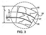
図1A及び1Bに示すように、ステント20は、管状部材21が、複数のバンド22とその間を延びて、隣接するバンドを連結する複数の連結部24により形成される形態を取る。 図2及び3に示すように、管状部材21は、多層25及び多界面層27(図示のように、3つの層25が2つの界面層27を交互に挟む)を有する多層構造体である。層25の各層は、層の厚み方向を横断して、1つ以上のグレイン29を含む。その結果として、管状部材21は、厚み方向を横断して多グレイン(図示のように3つ以上)を含む。理論によりくくられる必要性はなく、このグレイン微細構造により、ステント20の物理特性を高めることができると考えられる。 As shown in FIGS. 1A and 1B, the
使用中において、ステントは、比較的ハイレベルな応力及び疲労を経験してもよい。例えば、ステントは、拡張している場合や、湾曲した血管内に配置される場合において、搬送中に曲折した血管を通過して辿る際に折り曲げることができる。移植後に、ステントは、心臓の鼓動や、患者の呼吸に起因する運動からくる応力を経験してもよい。応力は、バンド及び連結部に緊張を与え、例えば、バンド及び連結部のうち少なくともいずれか一方を破断しうる。バンドや連結部が破断すると、血流を不通にする障壁となったり、血液が集合して血管内に好ましくない血栓症や凝固因子発生の原因となる部位となる。選択されたグレイン微細構造によってステントを製造することにより(例、ステントの厚みを横断して3つ以上のグレイン)、ステントの疲労耐性は高められる。結果として、バンド及び連結部は、破断の原因となる応力に対して更に耐久可能となるが、容易に変形可能な特性は維持される。 In use, the stent may experience a relatively high level of stress and fatigue. For example, a stent can be folded when it is passed through a bent blood vessel during delivery when it is expanded or placed in a curved blood vessel. After implantation, the stent may experience stress from the heartbeat and movement resulting from patient breathing. The stress gives tension to the band and the connecting portion, and for example, can break at least one of the band and the connecting portion. When the band or the connecting portion is broken, it becomes a barrier that prevents blood flow, or blood collects and becomes a site that causes undesired thrombosis and coagulation factors. By manufacturing a stent with a selected grain microstructure (eg, three or more grains across the thickness of the stent), the fatigue resistance of the stent is increased. As a result, the band and the connecting portion can be more durable against the stress that causes the breakage, but the easily deformable characteristics are maintained.
更に、ステントの製造方法において、ステントは、好ましくない微細構造を招来する1つ以上の熱処理の工程を受ける。例えば、熱処理は(等軸のグレインのような)好適な微細構造の原因となるが、同熱処理は、グレインが大きくなり、ステントの厚みを横断するグレインの数を減少させることを招来する。その結果、ステントは好ましくない疲労耐性を有することとなる。しかしながら、後述するように、ステントを多層25から製造して、製造中に層間における相互作用を制御することにより(例、界面の層27を使用することにより、或いは、熱処理を制御することにより)、グレイン構造体は、制御可能である。従って、ステントの疲労耐性も向上する。 Furthermore, in the method of manufacturing a stent, the stent undergoes one or more heat treatment steps that result in an undesirable microstructure. For example, heat treatment causes a suitable microstructure (such as equiaxed grains), but the heat treatment results in larger grains and a reduction in the number of grains across the thickness of the stent. As a result, the stent has undesirable fatigue resistance. However, as described below, a stent is manufactured from
層25は、物理特性を備える1つ以上の生態適合材料を含み、これによりステント20は、縮小され、続いて血管を支持するために拡張される。実施例において、ステント20は、20ksi(137.9MPa)乃至60ksi(413.7MPa)の最大抗張力(UTS)を有し、これにより、破裂するまで15%長く延びる。弾性係数は10msi(68.9GPa)乃至60msi(413.7GPa)である。ステント20が拡張される場合には、材料は、緊張に至るまで約30%張引される。材料の例としては、ステンレススチール(例、316L及び304Lのステンレススチール、及び、米国特許出願公開第2003−0018380−A1号明細書、第2002−0144757−A1号明細書、及び第2003−0077200−A1号明細書に開示される、ステンレススチール及び5乃至60重量%の1つ以上の放射線不透過性の要素(例、Pt、Ir、Au、W)を含む合金(登録商標PERSS))、ニチノール(ニッケル−チタン合金)、登録商標であるElgiloy、L605の合金、登録商標であるMP35N、チタン、チタンを含む合金(例、Ti−6Al−4V、Ti−50Ta、Ti−10Ir)、白金、白金を含む合金、ニオブ、ニオブを含む合金(Nb−1Zr)、Co−28Cr−6Mo、タンタル、及びタンタルを含む合金が挙げられる。材料のその他の例は、同一出願人による、2993年9月26日に出願された、発明の名称が「医療機器及びその製造方法」である米国特許出願第10/672891号明細書、及び、2005年1月3日に出願された、発明の名称が「医療機器及びその製造方法」である米国特許出願第11/035316号明細書に開示されている。その他の材料は、例えば、Schetsky L McdonaldによるEncyclopedia of Chemical Technology(第3版)、John Wiley & Sons出版、1982年、20巻、726乃至736ページの「形状記憶合金」の項、及び同一出願人による2003年1月17日に出願された米国特許出願第10/346487号明細書に開示された、超弾性を備えた、或いは、疑似弾性を備えた合金のような生体適合性金属を含む。
材料は、1つ以上の放射線不透過性を備えた材料を含み、これにより、放射線不透過性を提供する。放射線不透過性材料の例として、26以上の(例えば43以上の)原子番号を有する金属要素が挙げられる。実施例において、放射線不透過性材料は、約9.9g/cc以上の密度を有する。実施例において、放射線不透過性材料は、比較的X線を吸収する材料であって、例えば、100keVにおいて、25cm−1の線形減衰係数(例、少なくとも50cm−1)を有する。放射線不透過性材料の例として、タンタル、プラチナ、イリジウム、パラジウム、ハフニウム、タングステン、金、ルテニウム、及び、レニウムが挙げられる。放射線不透過性材料は、合金を含んでもよく、例えば、2つの、3つの、或いはより多くの複合の合金であって、上述した1つ以上の要素のほか、鉄、ニッケル、コバルトやチタンのような1つ以上の要素を含む。1つ以上の放射線不透過性材料を含む合金(例、登録商標PERSS)の例は、米国特許出願公開第2003−0018380−A1号明細書、第2002−0144757−A1号明細書、及び第2003−0077200−A1号明細書に開示されている。The material includes one or more radiopaque materials, thereby providing radiopacity. Examples of radiopaque materials include metal elements having an atomic number of 26 or greater (eg 43 or greater). In an embodiment, the radiopaque material has a density of about 9.9 g / cc or greater. In an embodiment, the radiopaque material is a material that is relatively x-ray absorbing and has a linear attenuation coefficient (eg, at least 50 cm−1 ) of 25 cm−1 at, for example, 100 keV. Examples of radiopaque materials include tantalum, platinum, iridium, palladium, hafnium, tungsten, gold, ruthenium, and rhenium. Radiopaque materials may include alloys, such as two, three, or more composite alloys, such as one or more of the elements described above, as well as iron, nickel, cobalt, and titanium. One or more of such elements. Examples of alloys that include one or more radiopaque materials (eg, registered trademark PERSS) are disclosed in US 2003-0018380-A1, 2002-0144757-A1, and 2003. -0077200-A1 specification.
実施例において、ステント20は、磁気共鳴映像法(MRI)による視認性を高める1つ以上の材料を含む。MRI材料の例としては、常磁性要素(例、ジスプロシウムやガドリニウム)を含む、テルビウム−ジスプロシウム、ジスプロシウム、ガドリニウムのような鉄合金、ジスプロシウムやガドリニウムの酸化や炭化された層(例、Dy2O3やGd2O3)により積層された非鉄金属のバンド、ナノ結晶Fe3O4、CoFe2O4、MnFe2O4や、MgFe2O4のような超常磁性材料の層により積層された非鉄金属(例、銅、銀、白金や、金属)、及び、遷移金属酸化物(例、酸化鉄、酸化コバルト、酸化ニッケル)のナノ結晶粒子が挙げられる。これに代えて、或いは付加的に、ステント20は、磁化率による影響を抑止するように磁化率が低い1つ以上の材料を含んでもよい。同材料は、スキャンの間、例えば、ステントに隣接しているか包囲する組織のスキャンに整合する。磁化率の低い材料としては、タンタル、白金、チタン、ニオブ、銅、及び、これらの要素を含む合金が挙げられる。MRIにおいて可視な材料は、構造材料に組み込まれて、構造材料として供給されるか、ステント20の層として含まれる。In an embodiment, the
層25は、それぞれ同じ構成であってもよく、別の構成であってもよく、また、様々な組み合わせから構成されてもよい。
層25(T1)の厚みは、管状部材21における多層25の機能を示し、例えば、対象となる物理特性や、ステントのタイプである。実施例において、層25の厚み(T1)は、約0.01mm乃至約0.08mmの範囲である。例えば、厚みT1は、約0.08mm以下であってもよい(例、約0.06mm以下、約0.04mm以下、約0.02mm以下)。ステントの層25の各層は、同じ厚みを有しても、異なる厚みを有してもよく、或いは、厚みの様々な組み合わせであってもよい。The
The thickness of the layer 25 (T1 ) indicates the function of the multilayer 25 in the
界面層27は、隣接する層25間にグレインの境界を差し挟むことができる1つ以上の生体適合性材料を含む。界面層27は、例えば、隣接する層を強力に接着可能な様々な材料を含み、隣接する層とは異なる寸法のグレインや構成を有する。実施例において、界面層27の材料は、隣接する層と比較して、異なるグレインの成長特性を有する。界面層27は、層25に関して上述した材料から構成可能である。 The
層25と類似して、界面層27の厚み(Ti)は、管状部材21における多層27の機能を示し、例えば、対象となる物理特性や、ステントのタイプである。実施例において、層27の厚み(Ti)は、約0.01mm乃至約0.08mmの範囲である。例えば、厚みTiは、約0.08mm以下であってもよい(例、約0.06mm以下、約0.04mm以下、約0.02mm以下)。ステントの層27の厚みは、同じ厚みを有しても、異なる厚みを有してもよい。Similar to the
これらに加えて、層25及び界面層27は、ステント20のバンド22の厚みTbを形成する。実施例において、厚みTbは、約0.05mm乃至約0.2mmの範囲である。例えば、バンド22の厚みTbは、約0.2mm以下であり(例、約0.1mm以下、約0.08mm以下、約0.06mm以下)である。In addition to these, the
厚みTbに沿って、層25及び界面層27は、3つ以上の層を形成する。例えば、ステント20は、4つ以上の層、5つ以上の層、6つ以上の層、7つ以上の層を含む。実施例において、ステント20は、隣接する層25の間において界面層27を含まない。別例において、ステント20は、隣接する層25の間において、多くの界面層27を含む。Along the thickness Tb, the
層25の各層は、厚みT1を横断して、1つ以上のグレイン29を含む。その結果、ステント20を横断するグレイン29の数は、層25の数の機能を示す。層の数が増加するにつれて、ステント20の厚みTbを横断してグレインの数もまた増加する。ステント20の厚みTbを横断してグレイン29(或いは層25)の数が増加すると、ステントの疲労強度が増し、ステントに沿って好適に応力が分散される。Each layer of
実施例において、1つ以上の層は、米国材料試験協会によるE112の平均値が6乃至12であるグレイン29を有する(米国材料試験協会によるE112の値は、グレインの直径の平均値に反比例する)。例えば、米国材料試験協会によるE112の値は、約6、約7、約8、約9、約10、約11、或いは約12である。実施例において、グレインの直径の平均値は、約5ミクロン乃至約45ミクロンの範囲である。例えば、グレインの直径の平均値は、約45ミクロン、40ミクロン、35ミクロン、30ミクロン、25ミクロン、20ミクロン、15ミクロンや、10ミクロン以下であるか、約5ミクロン、10ミクロン、15ミクロン、20ミクロン、25ミクロン、30ミクロン、35ミクロンや、40ミクロン以上である。ステント20が、ニオブ、タンタル、タングステンのような1つ以上の耐熱性を備えた金属を含む実施例において、グレインの直径は、脆弱性を減少させるために、好適なもの(例、約25ミクロン以下、約20ミクロン以下、約15ミクロン以下、約10ミクロン以下)である。 In an embodiment, one or more layers have a
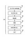
図4は、ステント20の製造方法30を示す。図示のように、方法30は、同心円状に多管を相互に配置する工程(ステップS32)を含む。次に多管は、下方に張引され(ステップS34)、多層の厚みを減少させる。その結果、多層の管状部材が形成される。多層の管状部材は、熱処理されて(ステップS36)、多層間において接着剤(例、拡散接着剤)を形成し、層を形成する材料のグレイン構造体を変化させる。多層の管状部材は、続いて切断されてバンド22及び連結部24を形成し(ステップS38)、未完成のステントを形成する。切断により影響を受けた未完成のステントの領域は、続いて取り払われる(ステップS40)。最後に、未完成のステントは、電解研磨により完成し、例えば、ステント20を形成する(ステップS42)。 FIG. 4 shows a
図4に示すように、方法30の最初のステップは、同心円状に多管を相互に配置して(ステップS32)、ステント20を形成するための多層の管状部材を形成する。より詳細には、様々な直径を有する多管は、相互に係合する。管は、例えば、「滑り嵌め」配置により構成される。最小の直径を有する管は、管状部材の最も内側の部分に最終的に配置され、最大の直径を有する管は、管状部材の最も外側の部分に最終的に配置される。管の(内部或いは外部の)直径は、約0.5mm乃至約5mmの範囲である。(図2及び3に示すように)加工後において、多管は、ステント20の層25となる。 As shown in FIG. 4, the first step of the
(図2及び3に示すように)実施例において、1つ以上の界面層27は、隣接する管の層25の間に配置される。界面層27の補助により、熱処理の間において隣接する管のグレインが溶融することが防止される。界面層27は、例えば、多層の管状部材内に同心円状に配置された1つ以上の追加の管であってもよい。別例において、界面層27は、化学気相蒸着法、物理気相蒸着法や、スパッタ法のような様々なその他の技術を使用して管上に堆積させてもよい。例えば、管を同心円状に配置するに先立って、界面層27は、1つ以上の上述した技術を使用して管に適応可能である。実施例において、界面層27は、隣接する各管の間に配置される。実施例において、多界面層27(例、界面層27に対応する多管)が、管の隣接する層25の間に配置される。界面の材料(例、界面層27を形成する材料)は、層25の管の組成とは異なる組成であってもよい。 In an embodiment (as shown in FIGS. 2 and 3), one or more
多管を同心円状に配置した後、上述したように、管状部材が形成されて(例、熱力学的に形成される)、管の厚みを減少させる(ステップS34)。例えば、管状部材は、一連のダイから打ち抜きにより形成可能であり、徐々に小さくなる円状の開口部を形成していき、部材を成形的に目的とする寸法及び形状に変形する。一連のダイから管状部材を打ち抜くことにより、管の厚みは減少し、所望の厚みを有する多層を形成することができる。実施例において、成型的形成における張引により、部材は堅固なものとなり(降伏強度を増し)、部材の長手軸方向に沿って、グレインを延ばす。張引工程により、隣接する管の間を機械的に更に連結する。例えば、張引工程の間において、比較的高い圧力及び高温を経験することにより、隣接する管が相互に連結する原因となる。 After arranging the multiple tubes concentrically, a tubular member is formed (eg, thermodynamically formed) as described above to reduce the tube thickness (step S34). For example, the tubular member can be formed by punching from a series of dies, forming a circular opening that gradually decreases, and deforming the member to the desired size and shape in a molding manner. By punching the tubular member from a series of dies, the thickness of the tube is reduced and a multilayer having the desired thickness can be formed. In an embodiment, the pulling in the forming process makes the member stiff (increased yield strength) and extends the grain along the longitudinal axis of the member. By the drawing process, the adjacent pipes are further mechanically connected. For example, experiencing relatively high pressures and high temperatures during the tensioning process can cause adjacent tubes to interconnect.
実施例において、多管を配置する工程及び管を加工する工程は、交互に行われてもよい。例えば、2つの管が同心円状に相互に配置されてから加工されてもよい。続いて、第3の管が、同心円状に加工した管に対して配置され、3層の管状部材が形成されてから加工されてもよい。このような交互の工程は、管状部材が所望の数値の層を形成するまで繰り返されてもよい。 In the embodiment, the step of arranging the multiple tubes and the step of processing the tubes may be performed alternately. For example, two tubes may be processed after being arranged concentrically with each other. Subsequently, the third tube may be arranged with respect to the tube processed concentrically, and may be processed after a three-layer tubular member is formed. Such alternating steps may be repeated until the tubular member forms the desired number of layers.
加工後において、管状部材は熱処理されて、微細構造を変化させる(ステップS36)。例えば、管状部材は、熱処理されて、微細構造を変化させてもよい(ステップS36)。例えば、管状部材は、再結晶温度以上において焼きなましたり、熱平衡に押圧して、延びたグレイン構造体を最初のグレイン構造体に、即ち、等軸結晶粒からなる構造体に変化させる。比較的短い時間、再結晶温度付近で材料を加熱することにより、小型の、或いは微細なグレインが形成可能である。グレインの成長を促進するようにより高い温度で、或いはより長い時間材料を過熱することにより、大型の、或いはきめの粗いグレインが形成可能である。熱処理の間において、グレインは成長し、相互に溶融する傾向を有するが、界面層27を使用することにより、隣接する管のグレインは、相互に溶融することを抑止される。各層(例、界面層27及び管)のグレインは、例えば、相互に略独立して成長可能である。その結果、多層及び多グレインが、熱処理を通して維持可能となり、管状部材の疲労強度が上昇可能である。 After processing, the tubular member is heat treated to change the microstructure (step S36). For example, the tubular member may be heat treated to change the microstructure (step S36). For example, the tubular member is annealed above the recrystallization temperature or pressed into thermal equilibrium to change the extended grain structure to the initial grain structure, ie, a structure consisting of equiaxed grains. By heating the material near the recrystallization temperature for a relatively short time, small or fine grains can be formed. Larger or coarser grains can be formed by heating the material at higher temperatures or for longer periods of time to promote grain growth. During the heat treatment, the grains tend to grow and melt together, but by using the
熱力学的工程(ステップS34)及び熱処理工程(ステップS36)は、管状部材が所望の厚み及びグレイン構造となるまで繰り返されてもよい。実施例において、これらの工程は、2(例、3,4,5,10)回以上行われる。 The thermodynamic process (step S34) and the heat treatment process (step S36) may be repeated until the tubular member has a desired thickness and grain structure. In the embodiment, these steps are performed 2 (eg, 3, 4, 5, 10) times or more.
実施例において、管状部材は、多層の管状部材を完全に形成するに先立って、熱処理されてもよい。例えば、多管が同心円状に配置されて、交互に加工される実施例において、部分的に形成された管状部材は、1つ以上の管配置工程及び加工工程の間において熱処理されてもよい。これに代えて、或いは、付加的に、管は、同心円状に配置されて多層の管状部材を形成するに先立って熱処理されてもよい。 In embodiments, the tubular member may be heat treated prior to complete formation of the multilayer tubular member. For example, in embodiments where multiple tubes are concentrically arranged and are alternately processed, the partially formed tubular member may be heat treated between one or more tube placement and processing steps. Alternatively or additionally, the tubes may be heat treated prior to being arranged concentrically to form a multi-layer tubular member.
実施例において、ステントを横断するグレイン構造が多岐にわたるように、熱処理に先立って、管状部材の1つ以上の部分は選択的にマスクされてもよい。その結果、ステントは、強度、剛性、及び延性のような様々な物理特性の領域を備える。例えば、管状部材の選択された部分は、研磨された反射コーティング(例、連結部上)により覆われたり、黒化したコーティング(例、バンド上)により覆われてもよい。(金、白金や、銀のような)研磨された反射コーティングは、管状部材に伝導する熱量を減少可能である。(黒鉛のような)黒化したコーティングは、管状部材に伝導する熱量を増加可能である。 In an embodiment, one or more portions of the tubular member may be selectively masked prior to heat treatment so that the grain structure across the stent varies. As a result, the stent comprises regions of varying physical properties such as strength, stiffness, and ductility. For example, selected portions of the tubular member may be covered with a polished reflective coating (eg, on a connection) or covered with a blackened coating (eg, on a band). Polished reflective coatings (such as gold, platinum and silver) can reduce the amount of heat conducted to the tubular member. Blackened coatings (such as graphite) can increase the amount of heat conducted to the tubular member.
図示のように、次に、多層のステント20のバンド22及び連結部24が、管を切断することにより形成される(ステップ38)。例えば、米国特許第5780807号明細書に開示されているように、管の選択された部分が取り去られ、バンド22及び連結部24をレーザー切断により形成する。実施例において、レーザー切断の間に、水溶液や油のような液体搬送部が、管の管腔を通過して流れる。搬送部は、管の一部上に形成される滓が再び別の部位上において再堆積することを抑止するか、管上における鋳造材料の形成を減少させる。これに代えて、或いは付加的に、管の部分を取り去るその他の方法、例えば、機械的加工(例、微細加工)、放電加工(EDM)、及び、フォトエッチング(例、酸性のフォトエッチング)を使用してもよい。 As shown, the
実施例において、バンド22及び連結部24が形成された後に、上述した切断処理を施した多層の管の領域が取り払われる(ステップS40)。例えば、バンド22及び連結部24のレーザー加工により、多層のステント20の力学的性質及び性能に悪影響を与える溶融し再凝固した材料や酸化した金属の表層を取り去ることができる。悪影響を受けた領域は、機械的に(例えば、粒子粉砕や研ぎにより)、或いは、化学的に(例えば、エッチングや電解研磨により)取り払わる。実施例において、管状部材は、ステップS36が実施された後、ニアネット寸法に形成可能である。「ニアネット寸法」とは、管が、ステントを完成させるために取り払う材料の比較的薄い膜を有することを指す。実施例において、管は約25%以下の拡張により形成される。例えば、約15%、10%、5%以下の拡張である。 In the embodiment, after the
未完成であったステントが完成し、ステント20を形成する(ステップS42)。未完成のステントは、例えば、電解研磨により円滑に完成する。未完成のステントはニアネット寸法に形成可能であるため、未完成のステントの一部を比較的ほとんど取り去ることなくステントは完成する。その結果、(ステントを損傷しうる)更なる工程及びハイコストな材料を減少させることができる。実施例においては、ステントの材料の約0.0025mmは、化学研磨や電解研磨により取り払われ、ステントを形成する。 The incomplete stent is completed and the
ステント20は、所望の形状および寸法から構成されてもよい(例えば、冠動脈ステント、大動脈ステント、末梢血管ステント、胃腸ステント、泌尿器ステント、神経ステントがある)。用途に応じて、ステント20は、例えば、1mm乃至46mmの拡張径を有してもよい。特定の実施例においては、冠動脈ステントは、約2mm乃至約6mmの拡張径を有してもよい。幾つかの実施例においては、末梢血管ステントは、約5mm乃至約24mmの拡張径を有してもよい。特定の実施例においては、胃腸ステントや泌尿器ステントは、約6mm乃至約30mmの拡張径を有してもよい。幾つかの実施例においては、神経ステントは、約1mm乃至約12mmの拡張径を有してもよい。腹部大動脈瘤(AAA)ステント及び胸部大動脈瘤(TAA)ステントは、約20mm乃至約46mmの直径を有してもよい。ステント20は、バルーン拡張型、自己拡張型、あるいはこれらの組合せであってもよい(例えば、米国特許第5366504号明細書に開示されている)。 The
使用に際して、ステント20は、カテーテル搬送システムにより、使用してもよく、例えば、搬送及び拡張されてもよい。カテーテルシステムは、例えば、Wangの米国特許第5195969号明細書、Hamlinの米国特許第5270086号明細書、及びRaeder−Devensの米国特許第6726712号明細書に開示されている。ステント及びステントの搬送は、ミネソタ州Maple GroveのBoston Schentific Scimedから入手可能である、登録商標がRadiusやSymbiotであるシステムを例とする。 In use, the
多くの実施例を説明したが、本発明は、これらに限定されない。
一例として、連結部24はバンド22とは異なった寸法を有し、多層構造をとることができる。図1に示すように、例えば、連結部の幅(Wc)は、バンド22の幅(Wb)より狭く、これにより、連結部は湾曲して血管に対して適応可能となる。ここで使用されるように、連結部24は、ステントのバンドから延びるステントの一部を示し、例えば、ステントの長手方向に沿って、第1のバンドから隣接する第2のバンドに延びる。(図1に示すように、)連結部は、1つの支柱、或いは複数の支柱を含む。連結部は、線形にも(例、ステントの長手軸方向に平行に)非線形にも延び、例えば、ステントの周囲を包囲するように延びる。ここで使用されるように、バンド22は、ステントの周囲を包囲するように延びるステントの一部を示す。バンドはステントの円周の周囲全体に延びて、これにより、例えば、バンドの両端が結合されるか、バンドが円周の周囲を部分的に延びる。バンドは略線形か非線型に延び、例えば、図1A及び1Bに示すように、うねったパターンやジグザグのパターンにより延びる。実施例において、バンド22は、一体的に形成されて、バンド間を横切って延びる連結部により一体的に連結される。バンドの幅の例は、2004年10月8日に出願された、発明の名称が「医療用具及びその製造方法」であり出願人が同一である米国特許出願第10/961289号明細書に開示される。Although many embodiments have been described, the present invention is not limited thereto.
As an example, the connecting
実施例において、連結部24の幅(Wc)は、約0.030mm乃至約0.3mmの範囲である。連結部24の特定の幅は、ステント20における材料の機能を示し、例えば、ステントのタイプや所望の性能を示す。例えば、316Lのステンレススチールを含むステントの連結部の幅Wcは、約0.05mm乃至約0.2mmの範囲である。登録商標であるPERSSの合金を含むステントの連結部の幅Wcは、約0.03mm乃至約0.18mmの範囲である。クロム及びコバルトを有する合金を含むステントの連結部の幅Wcは、約0.08mm乃至0.30mmの範囲である。チタンを有する合金を含むステントの連結部の幅Wcは、約0.03mm乃至約0.15mmの範囲である。In the embodiment, the width (Wc ) of the connecting
実施例において、連結部24は、幅Wcを横切って1つ以上のグレインを含む。例えば、連結部24は、幅Wcを横切って少なくとも3つのグレイン(例、少なくとも4つのグレイン、少なくとも5つのグレインや、少なくとも6つのグレイン)を有する。実施例において、連結部24は、グレインの径において、米国材料試験協会E112による約6以下の平均値を有する。グレイン径の平均値は、例えば、約5ミクロン乃至45ミクロンの範囲である。例えば、グレイン径の平均値は、約45ミクロン、40ミクロン、35ミクロン、30ミクロン、25ミクロン、20ミクロン、15ミクロンや、10ミクロン以下であるか、約5ミクロン、10ミクロン、15ミクロン、20ミクロン、25ミクロン、30ミクロン、35ミクロンや、40ミクロン以上である。連結部24が、ニオブ、タンタル、タングステンのような1つ以上の耐熱性を備えた金属を含む実施例において、グレインの直径は、脆弱性を減少させるために、好適なもの(例、約25ミクロン以下、約20ミクロン以下、約15ミクロン以下、約10ミクロン以下)である。In embodiments, the connecting
(図1に示すように)、実施例において、連結部24は、上述した管状部材21の連結部の厚みTcを横切って多グレイン(例、3か4)を含んでもよい。
実施例において、ステント20は、柔軟な材料の少なくとも1つの層及び堅固な材料の少なくとも1つの層を含む。例えば、柔軟性を備え打ち延べられる材料から形成される層を強度の高い材料から形成される層に隣接して配置してもよい。結果として、ステントの強度の高い材料から形成されるステントの間において問題を引き起こす、ステントの巻き付きを減少させる。In the embodiment (as shown in FIG. 1), the connecting
In an embodiment, the
ステント20は、カバー付きステントやステントグラフトの一部であってもよい。実施例において、ステント20は、ポリテトラフルオロエチレン(PTFE)、拡張されたPTFE、ポリエチレン、ウレタン又はポリプロピレンから形成される、生体適合性を備えた無孔性又は半有孔性ポリマーマトリックスを有してもよく、同ポリマーマトリックスに装着されてもよい。 The
ステント20は、米国特許第5674242号明細書、2001年7月2日付けで出願された米国特許出願公開第09/895415号明細書、及び、2002年8月30日付けで出願された米国特許出願公開第10/232265号明細書に開示されているような、解放可能な治療薬や薬学的に活性のある化合物を含んでもよい。治療薬や薬学的に活性のある化合物には、例えば、抗血栓剤、酸化防止剤、抗炎症剤、麻酔剤、抗血液凝固剤、及び抗生物質等を含んでもよい。
その他の実施例において、ここで開示される構造体及び方法は、その他の医療用具の製造にも使用可能である。例えば、ここで開示される構造体及び方法は、ハイポチューブカテーテルシャフトやガイドワイヤのような器具の製造に使用可能である。 In other embodiments, the structures and methods disclosed herein can be used in the manufacture of other medical devices. For example, the structures and methods disclosed herein can be used in the manufacture of instruments such as hypotube catheter shafts and guide wires.
他の実施例は、特許請求の範囲内にある。 Other embodiments are within the scope of the claims.
Claims (32)
Translated fromJapaneseApplications Claiming Priority (2)
| Application Number | Priority Date | Filing Date | Title |
|---|---|---|---|
| US11/122,819US20060259126A1 (en) | 2005-05-05 | 2005-05-05 | Medical devices and methods of making the same |
| PCT/US2006/017475WO2006121890A2 (en) | 2005-05-05 | 2006-05-04 | Medical devices and methods of making the same |
Publications (1)
| Publication Number | Publication Date |
|---|---|
| JP2008539898Atrue JP2008539898A (en) | 2008-11-20 |
Family
ID=37191375
Family Applications (1)
| Application Number | Title | Priority Date | Filing Date |
|---|---|---|---|
| JP2008510278APendingJP2008539898A (en) | 2005-05-05 | 2006-05-04 | Medical device and manufacturing method thereof |
Country Status (6)
| Country | Link |
|---|---|
| US (1) | US20060259126A1 (en) |
| EP (1) | EP1877112B1 (en) |
| JP (1) | JP2008539898A (en) |
| AT (1) | ATE538819T1 (en) |
| CA (1) | CA2606546A1 (en) |
| WO (1) | WO2006121890A2 (en) |
Cited By (3)
| Publication number | Priority date | Publication date | Assignee | Title |
|---|---|---|---|---|
| WO2012020812A1 (en)* | 2010-08-12 | 2012-02-16 | 株式会社オプトニクス精密 | Stent |
| JP2016507314A (en)* | 2013-02-22 | 2016-03-10 | カーディアティス ソシエテ アノニム | Medical devices visible in MRI |
| US11517763B2 (en) | 2011-06-17 | 2022-12-06 | Signify Holding B.V. | Light-emitting device and photo-therapy device comprising a light-emitting device |
Families Citing this family (13)
| Publication number | Priority date | Publication date | Assignee | Title |
|---|---|---|---|---|
| US7250058B1 (en) | 2000-03-24 | 2007-07-31 | Abbott Cardiovascular Systems Inc. | Radiopaque intraluminal stent |
| US7344560B2 (en)* | 2004-10-08 | 2008-03-18 | Boston Scientific Scimed, Inc. | Medical devices and methods of making the same |
| JP5097536B2 (en)* | 2005-01-28 | 2012-12-12 | テルモ株式会社 | Endovascular implant |
| EP2020967B1 (en)* | 2006-05-12 | 2020-09-23 | Cardinal Health Switzerland 515 GmbH | Baloon expandable bioabsorbable drug eluting stent |
| JP2010504174A (en)* | 2006-09-21 | 2010-02-12 | クレベニー テクノロジーズ | Specially constructed and surface-modified medical devices with certain design features that take advantage of the unique properties of tungsten, zirconium, tantalum, and / or niobium |
| US8142490B2 (en)* | 2007-10-24 | 2012-03-27 | Cordis Corporation | Stent segments axially connected by thin film |
| WO2009126550A2 (en) | 2008-04-08 | 2009-10-15 | Med Institute, Inc. | Surface structure of a component of a medical device and a method of forming the surface structure |
| US9119906B2 (en)* | 2008-09-24 | 2015-09-01 | Integran Technologies, Inc. | In-vivo biodegradable medical implant |
| US11298251B2 (en) | 2010-11-17 | 2022-04-12 | Abbott Cardiovascular Systems, Inc. | Radiopaque intraluminal stents comprising cobalt-based alloys with primarily single-phase supersaturated tungsten content |
| US9566147B2 (en) | 2010-11-17 | 2017-02-14 | Abbott Cardiovascular Systems, Inc. | Radiopaque intraluminal stents comprising cobalt-based alloys containing one or more platinum group metals, refractory metals, or combinations thereof |
| US9724494B2 (en) | 2011-06-29 | 2017-08-08 | Abbott Cardiovascular Systems, Inc. | Guide wire device including a solderable linear elastic nickel-titanium distal end section and methods of preparation therefor |
| US20130096669A1 (en)* | 2011-10-12 | 2013-04-18 | Abbott Cardiovascular Systems, Inc. | Partially annealed stent |
| US12151049B2 (en) | 2019-10-14 | 2024-11-26 | Abbott Cardiovascular Systems, Inc. | Methods for manufacturing radiopaque intraluminal stents comprising cobalt-based alloys with supersaturated tungsten content |
Family Cites Families (47)
| Publication number | Priority date | Publication date | Assignee | Title |
|---|---|---|---|---|
| SE445884B (en)* | 1982-04-30 | 1986-07-28 | Medinvent Sa | DEVICE FOR IMPLANTATION OF A RODFORM PROTECTION |
| US4958625A (en)* | 1989-07-18 | 1990-09-25 | Boston Scientific Corporation | Biopsy needle instrument |
| DE69002295T2 (en)* | 1989-09-25 | 1993-11-04 | Schneider Usa Inc | MULTILAYER EXTRUSION AS A METHOD FOR PRODUCING BALLOONS FOR VESSEL PLASTICS. |
| US5477864A (en)* | 1989-12-21 | 1995-12-26 | Smith & Nephew Richards, Inc. | Cardiovascular guidewire of enhanced biocompatibility |
| US5090419A (en)* | 1990-08-23 | 1992-02-25 | Aubrey Palestrant | Apparatus for acquiring soft tissue biopsy specimens |
| US5195969A (en)* | 1991-04-26 | 1993-03-23 | Boston Scientific Corporation | Co-extruded medical balloons and catheter using such balloons |
| US5366504A (en)* | 1992-05-20 | 1994-11-22 | Boston Scientific Corporation | Tubular medical prosthesis |
| EP0633798B1 (en)* | 1992-03-31 | 2003-05-07 | Boston Scientific Corporation | Vascular filter |
| US5630840A (en)* | 1993-01-19 | 1997-05-20 | Schneider (Usa) Inc | Clad composite stent |
| WO1994016646A1 (en)* | 1993-01-19 | 1994-08-04 | Schneider (Usa) Inc. | Clad composite stent |
| WO1995029646A1 (en)* | 1994-04-29 | 1995-11-09 | Boston Scientific Corporation | Medical prosthetic stent and method of manufacture |
| CA2301351C (en)* | 1994-11-28 | 2002-01-22 | Advanced Cardiovascular Systems, Inc. | Method and apparatus for direct laser cutting of metal stents |
| US6896696B2 (en)* | 1998-11-20 | 2005-05-24 | Scimed Life Systems, Inc. | Flexible and expandable stent |
| US5674242A (en)* | 1995-06-06 | 1997-10-07 | Quanam Medical Corporation | Endoprosthetic device with therapeutic compound |
| US6099561A (en)* | 1996-10-21 | 2000-08-08 | Inflow Dynamics, Inc. | Vascular and endoluminal stents with improved coatings |
| US6387121B1 (en)* | 1996-10-21 | 2002-05-14 | Inflow Dynamics Inc. | Vascular and endoluminal stents with improved coatings |
| US5858556A (en)* | 1997-01-21 | 1999-01-12 | Uti Corporation | Multilayer composite tubular structure and method of making |
| US6569270B2 (en)* | 1997-07-11 | 2003-05-27 | Honeywell International Inc. | Process for producing a metal article |
| US6340367B1 (en)* | 1997-08-01 | 2002-01-22 | Boston Scientific Scimed, Inc. | Radiopaque markers and methods of using the same |
| NO311781B1 (en)* | 1997-11-13 | 2002-01-28 | Medinol Ltd | Metal multilayer stents |
| US6342062B1 (en)* | 1998-09-24 | 2002-01-29 | Scimed Life Systems, Inc. | Retrieval devices for vena cava filter |
| US6245104B1 (en)* | 1999-02-28 | 2001-06-12 | Inflow Dynamics Inc. | Method of fabricating a biocompatible stent |
| US6264595B1 (en)* | 1999-02-04 | 2001-07-24 | Mobeta, Inc. | Radioactive transition metal stents |
| US6171327B1 (en)* | 1999-02-24 | 2001-01-09 | Scimed Life Systems, Inc. | Intravascular filter and method |
| US6620192B1 (en)* | 1999-03-16 | 2003-09-16 | Advanced Cardiovascular Systems, Inc. | Multilayer stent |
| US6726712B1 (en)* | 1999-05-14 | 2004-04-27 | Boston Scientific Scimed | Prosthesis deployment device with translucent distal end |
| US6146404A (en)* | 1999-09-03 | 2000-11-14 | Scimed Life Systems, Inc. | Removable thrombus filter |
| US6379383B1 (en)* | 1999-11-19 | 2002-04-30 | Advanced Bio Prosthetic Surfaces, Ltd. | Endoluminal device exhibiting improved endothelialization and method of manufacture thereof |
| AU2001229351A1 (en)* | 2000-01-25 | 2001-08-07 | Boston Scientific Limited | Manufacturing medical devices by vapor deposition |
| CA2398547A1 (en)* | 2000-02-09 | 2001-08-16 | Nikolai G. Sedelnikov | Non-thrombogenic implantable devices |
| US20020144757A1 (en)* | 2000-07-07 | 2002-10-10 | Craig Charles Horace | Stainless steel alloy with improved radiopaque characteristics |
| US20030018380A1 (en)* | 2000-07-07 | 2003-01-23 | Craig Charles H. | Platinum enhanced alloy and intravascular or implantable medical devices manufactured therefrom |
| US20030077200A1 (en)* | 2000-07-07 | 2003-04-24 | Craig Charles H. | Enhanced radiopaque alloy stent |
| US7101391B2 (en)* | 2000-09-18 | 2006-09-05 | Inflow Dynamics Inc. | Primarily niobium stent |
| US6478815B1 (en)* | 2000-09-18 | 2002-11-12 | Inflow Dynamics Inc. | Vascular and endoluminal stents |
| US6767360B1 (en)* | 2001-02-08 | 2004-07-27 | Inflow Dynamics Inc. | Vascular stent with composite structure for magnetic reasonance imaging capabilities |
| US7201940B1 (en)* | 2001-06-12 | 2007-04-10 | Advanced Cardiovascular Systems, Inc. | Method and apparatus for thermal spray processing of medical devices |
| US6676987B2 (en)* | 2001-07-02 | 2004-01-13 | Scimed Life Systems, Inc. | Coating a medical appliance with a bubble jet printing head |
| US8562664B2 (en)* | 2001-10-25 | 2013-10-22 | Advanced Cardiovascular Systems, Inc. | Manufacture of fine-grained material for use in medical devices |
| US7462366B2 (en)* | 2002-03-29 | 2008-12-09 | Boston Scientific Scimed, Inc. | Drug delivery particle |
| US6865810B2 (en)* | 2002-06-27 | 2005-03-15 | Scimed Life Systems, Inc. | Methods of making medical devices |
| US7029495B2 (en)* | 2002-08-28 | 2006-04-18 | Scimed Life Systems, Inc. | Medical devices and methods of making the same |
| US20040143317A1 (en)* | 2003-01-17 | 2004-07-22 | Stinson Jonathan S. | Medical devices |
| EP1444993B2 (en)* | 2003-02-10 | 2013-06-26 | W.C. Heraeus GmbH | Improved metal alloy for medical devices and implants |
| US20050070990A1 (en)* | 2003-09-26 | 2005-03-31 | Stinson Jonathan S. | Medical devices and methods of making same |
| US20050131522A1 (en)* | 2003-12-10 | 2005-06-16 | Stinson Jonathan S. | Medical devices and methods of making the same |
| US7344560B2 (en)* | 2004-10-08 | 2008-03-18 | Boston Scientific Scimed, Inc. | Medical devices and methods of making the same |
- 2005
- 2005-05-05USUS11/122,819patent/US20060259126A1/ennot_activeAbandoned
- 2006
- 2006-05-04CACA002606546Apatent/CA2606546A1/ennot_activeAbandoned
- 2006-05-04EPEP06752339Apatent/EP1877112B1/ennot_activeNot-in-force
- 2006-05-04ATAT06752339Tpatent/ATE538819T1/enactive
- 2006-05-04WOPCT/US2006/017475patent/WO2006121890A2/enactiveApplication Filing
- 2006-05-04JPJP2008510278Apatent/JP2008539898A/enactivePending
Cited By (4)
| Publication number | Priority date | Publication date | Assignee | Title |
|---|---|---|---|---|
| WO2012020812A1 (en)* | 2010-08-12 | 2012-02-16 | 株式会社オプトニクス精密 | Stent |
| JP2012040050A (en)* | 2010-08-12 | 2012-03-01 | Optnics Precision Co Ltd | Stent |
| US11517763B2 (en) | 2011-06-17 | 2022-12-06 | Signify Holding B.V. | Light-emitting device and photo-therapy device comprising a light-emitting device |
| JP2016507314A (en)* | 2013-02-22 | 2016-03-10 | カーディアティス ソシエテ アノニム | Medical devices visible in MRI |
Also Published As
| Publication number | Publication date |
|---|---|
| ATE538819T1 (en) | 2012-01-15 |
| EP1877112B1 (en) | 2011-12-28 |
| US20060259126A1 (en) | 2006-11-16 |
| WO2006121890A3 (en) | 2007-11-08 |
| CA2606546A1 (en) | 2006-11-16 |
| EP1877112A2 (en) | 2008-01-16 |
| WO2006121890A2 (en) | 2006-11-16 |
Similar Documents
| Publication | Publication Date | Title |
|---|---|---|
| JP2008539898A (en) | Medical device and manufacturing method thereof | |
| EP1874221B1 (en) | Endoprosthesis | |
| US7749264B2 (en) | Medical devices and methods of making the same | |
| EP1866006B1 (en) | Medical devices including composites | |
| CA2442057C (en) | Medical device having radio-opacification and barrier layers | |
| JP2006515779A (en) | Medical device including two parts, one of which is less radiopaque than the other | |
| JP2008515563A6 (en) | Medical device and manufacturing method thereof | |
| US20100198336A1 (en) | Medical devices and methods of making the same | |
| JP2008541935A (en) | Endoprosthesis | |
| JP2010532222A (en) | Molybdenum prosthesis | |
| JP2010503468A (en) | Medical device with a porous surface |