JP2008539845A - Intervertebral disc prosthesis - Google Patents
Intervertebral disc prosthesisDownload PDFInfo
- Publication number
- JP2008539845A JP2008539845AJP2008509469AJP2008509469AJP2008539845AJP 2008539845 AJP2008539845 AJP 2008539845AJP 2008509469 AJP2008509469 AJP 2008509469AJP 2008509469 AJP2008509469 AJP 2008509469AJP 2008539845 AJP2008539845 AJP 2008539845A
- Authority
- JP
- Japan
- Prior art keywords
- intermediate member
- intervertebral disc
- edges
- disc prosthesis
- hemisphere
- Prior art date
- Legal status (The legal status is an assumption and is not a legal conclusion. Google has not performed a legal analysis and makes no representation as to the accuracy of the status listed.)
- Granted
Links
Images


Classifications
- A—HUMAN NECESSITIES
- A61—MEDICAL OR VETERINARY SCIENCE; HYGIENE
- A61F—FILTERS IMPLANTABLE INTO BLOOD VESSELS; PROSTHESES; DEVICES PROVIDING PATENCY TO, OR PREVENTING COLLAPSING OF, TUBULAR STRUCTURES OF THE BODY, e.g. STENTS; ORTHOPAEDIC, NURSING OR CONTRACEPTIVE DEVICES; FOMENTATION; TREATMENT OR PROTECTION OF EYES OR EARS; BANDAGES, DRESSINGS OR ABSORBENT PADS; FIRST-AID KITS
- A61F2/00—Filters implantable into blood vessels; Prostheses, i.e. artificial substitutes or replacements for parts of the body; Appliances for connecting them with the body; Devices providing patency to, or preventing collapsing of, tubular structures of the body, e.g. stents
- A61F2/02—Prostheses implantable into the body
- A61F2/30—Joints
- A61F2/44—Joints for the spine, e.g. vertebrae, spinal discs
- A61F2/442—Intervertebral or spinal discs, e.g. resilient
- A61F2/4425—Intervertebral or spinal discs, e.g. resilient made of articulated components
- A—HUMAN NECESSITIES
- A61—MEDICAL OR VETERINARY SCIENCE; HYGIENE
- A61F—FILTERS IMPLANTABLE INTO BLOOD VESSELS; PROSTHESES; DEVICES PROVIDING PATENCY TO, OR PREVENTING COLLAPSING OF, TUBULAR STRUCTURES OF THE BODY, e.g. STENTS; ORTHOPAEDIC, NURSING OR CONTRACEPTIVE DEVICES; FOMENTATION; TREATMENT OR PROTECTION OF EYES OR EARS; BANDAGES, DRESSINGS OR ABSORBENT PADS; FIRST-AID KITS
- A61F2/00—Filters implantable into blood vessels; Prostheses, i.e. artificial substitutes or replacements for parts of the body; Appliances for connecting them with the body; Devices providing patency to, or preventing collapsing of, tubular structures of the body, e.g. stents
- A61F2/02—Prostheses implantable into the body
- A61F2/30—Joints
- A61F2002/30001—Additional features of subject-matter classified in A61F2/28, A61F2/30 and subgroups thereof
- A61F2002/30108—Shapes
- A61F2002/3011—Cross-sections or two-dimensional shapes
- A61F2002/30112—Rounded shapes, e.g. with rounded corners
- A61F2002/30113—Rounded shapes, e.g. with rounded corners circular
- A—HUMAN NECESSITIES
- A61—MEDICAL OR VETERINARY SCIENCE; HYGIENE
- A61F—FILTERS IMPLANTABLE INTO BLOOD VESSELS; PROSTHESES; DEVICES PROVIDING PATENCY TO, OR PREVENTING COLLAPSING OF, TUBULAR STRUCTURES OF THE BODY, e.g. STENTS; ORTHOPAEDIC, NURSING OR CONTRACEPTIVE DEVICES; FOMENTATION; TREATMENT OR PROTECTION OF EYES OR EARS; BANDAGES, DRESSINGS OR ABSORBENT PADS; FIRST-AID KITS
- A61F2/00—Filters implantable into blood vessels; Prostheses, i.e. artificial substitutes or replacements for parts of the body; Appliances for connecting them with the body; Devices providing patency to, or preventing collapsing of, tubular structures of the body, e.g. stents
- A61F2/02—Prostheses implantable into the body
- A61F2/30—Joints
- A61F2002/30001—Additional features of subject-matter classified in A61F2/28, A61F2/30 and subgroups thereof
- A61F2002/30108—Shapes
- A61F2002/3011—Cross-sections or two-dimensional shapes
- A61F2002/30112—Rounded shapes, e.g. with rounded corners
- A61F2002/30133—Rounded shapes, e.g. with rounded corners kidney-shaped or bean-shaped
- A—HUMAN NECESSITIES
- A61—MEDICAL OR VETERINARY SCIENCE; HYGIENE
- A61F—FILTERS IMPLANTABLE INTO BLOOD VESSELS; PROSTHESES; DEVICES PROVIDING PATENCY TO, OR PREVENTING COLLAPSING OF, TUBULAR STRUCTURES OF THE BODY, e.g. STENTS; ORTHOPAEDIC, NURSING OR CONTRACEPTIVE DEVICES; FOMENTATION; TREATMENT OR PROTECTION OF EYES OR EARS; BANDAGES, DRESSINGS OR ABSORBENT PADS; FIRST-AID KITS
- A61F2/00—Filters implantable into blood vessels; Prostheses, i.e. artificial substitutes or replacements for parts of the body; Appliances for connecting them with the body; Devices providing patency to, or preventing collapsing of, tubular structures of the body, e.g. stents
- A61F2/02—Prostheses implantable into the body
- A61F2/30—Joints
- A61F2002/30001—Additional features of subject-matter classified in A61F2/28, A61F2/30 and subgroups thereof
- A61F2002/30316—The prosthesis having different structural features at different locations within the same prosthesis; Connections between prosthetic parts; Special structural features of bone or joint prostheses not otherwise provided for
- A61F2002/30535—Special structural features of bone or joint prostheses not otherwise provided for
- A61F2002/30563—Special structural features of bone or joint prostheses not otherwise provided for having elastic means or damping means, different from springs, e.g. including an elastomeric core or shock absorbers
- A—HUMAN NECESSITIES
- A61—MEDICAL OR VETERINARY SCIENCE; HYGIENE
- A61F—FILTERS IMPLANTABLE INTO BLOOD VESSELS; PROSTHESES; DEVICES PROVIDING PATENCY TO, OR PREVENTING COLLAPSING OF, TUBULAR STRUCTURES OF THE BODY, e.g. STENTS; ORTHOPAEDIC, NURSING OR CONTRACEPTIVE DEVICES; FOMENTATION; TREATMENT OR PROTECTION OF EYES OR EARS; BANDAGES, DRESSINGS OR ABSORBENT PADS; FIRST-AID KITS
- A61F2/00—Filters implantable into blood vessels; Prostheses, i.e. artificial substitutes or replacements for parts of the body; Appliances for connecting them with the body; Devices providing patency to, or preventing collapsing of, tubular structures of the body, e.g. stents
- A61F2/02—Prostheses implantable into the body
- A61F2/30—Joints
- A61F2002/30001—Additional features of subject-matter classified in A61F2/28, A61F2/30 and subgroups thereof
- A61F2002/30621—Features concerning the anatomical functioning or articulation of the prosthetic joint
- A61F2002/30649—Ball-and-socket joints
- A61F2002/30662—Ball-and-socket joints with rotation-limiting means
- A—HUMAN NECESSITIES
- A61—MEDICAL OR VETERINARY SCIENCE; HYGIENE
- A61F—FILTERS IMPLANTABLE INTO BLOOD VESSELS; PROSTHESES; DEVICES PROVIDING PATENCY TO, OR PREVENTING COLLAPSING OF, TUBULAR STRUCTURES OF THE BODY, e.g. STENTS; ORTHOPAEDIC, NURSING OR CONTRACEPTIVE DEVICES; FOMENTATION; TREATMENT OR PROTECTION OF EYES OR EARS; BANDAGES, DRESSINGS OR ABSORBENT PADS; FIRST-AID KITS
- A61F2/00—Filters implantable into blood vessels; Prostheses, i.e. artificial substitutes or replacements for parts of the body; Appliances for connecting them with the body; Devices providing patency to, or preventing collapsing of, tubular structures of the body, e.g. stents
- A61F2/02—Prostheses implantable into the body
- A61F2/30—Joints
- A61F2002/30001—Additional features of subject-matter classified in A61F2/28, A61F2/30 and subgroups thereof
- A61F2002/30667—Features concerning an interaction with the environment or a particular use of the prosthesis
- A61F2002/30682—Means for preventing migration of particles released by the joint, e.g. wear debris or cement particles
- A61F2002/30685—Means for reducing or preventing the generation of wear particulates
- A—HUMAN NECESSITIES
- A61—MEDICAL OR VETERINARY SCIENCE; HYGIENE
- A61F—FILTERS IMPLANTABLE INTO BLOOD VESSELS; PROSTHESES; DEVICES PROVIDING PATENCY TO, OR PREVENTING COLLAPSING OF, TUBULAR STRUCTURES OF THE BODY, e.g. STENTS; ORTHOPAEDIC, NURSING OR CONTRACEPTIVE DEVICES; FOMENTATION; TREATMENT OR PROTECTION OF EYES OR EARS; BANDAGES, DRESSINGS OR ABSORBENT PADS; FIRST-AID KITS
- A61F2/00—Filters implantable into blood vessels; Prostheses, i.e. artificial substitutes or replacements for parts of the body; Appliances for connecting them with the body; Devices providing patency to, or preventing collapsing of, tubular structures of the body, e.g. stents
- A61F2/02—Prostheses implantable into the body
- A61F2/30—Joints
- A61F2/30767—Special external or bone-contacting surface, e.g. coating for improving bone ingrowth
- A61F2/30771—Special external or bone-contacting surface, e.g. coating for improving bone ingrowth applied in original prostheses, e.g. holes or grooves
- A61F2002/30772—Apertures or holes, e.g. of circular cross section
- A61F2002/30784—Plurality of holes
- A—HUMAN NECESSITIES
- A61—MEDICAL OR VETERINARY SCIENCE; HYGIENE
- A61F—FILTERS IMPLANTABLE INTO BLOOD VESSELS; PROSTHESES; DEVICES PROVIDING PATENCY TO, OR PREVENTING COLLAPSING OF, TUBULAR STRUCTURES OF THE BODY, e.g. STENTS; ORTHOPAEDIC, NURSING OR CONTRACEPTIVE DEVICES; FOMENTATION; TREATMENT OR PROTECTION OF EYES OR EARS; BANDAGES, DRESSINGS OR ABSORBENT PADS; FIRST-AID KITS
- A61F2/00—Filters implantable into blood vessels; Prostheses, i.e. artificial substitutes or replacements for parts of the body; Appliances for connecting them with the body; Devices providing patency to, or preventing collapsing of, tubular structures of the body, e.g. stents
- A61F2/02—Prostheses implantable into the body
- A61F2/30—Joints
- A61F2/30767—Special external or bone-contacting surface, e.g. coating for improving bone ingrowth
- A61F2/30771—Special external or bone-contacting surface, e.g. coating for improving bone ingrowth applied in original prostheses, e.g. holes or grooves
- A61F2002/30841—Sharp anchoring protrusions for impaction into the bone, e.g. sharp pins, spikes
- A—HUMAN NECESSITIES
- A61—MEDICAL OR VETERINARY SCIENCE; HYGIENE
- A61F—FILTERS IMPLANTABLE INTO BLOOD VESSELS; PROSTHESES; DEVICES PROVIDING PATENCY TO, OR PREVENTING COLLAPSING OF, TUBULAR STRUCTURES OF THE BODY, e.g. STENTS; ORTHOPAEDIC, NURSING OR CONTRACEPTIVE DEVICES; FOMENTATION; TREATMENT OR PROTECTION OF EYES OR EARS; BANDAGES, DRESSINGS OR ABSORBENT PADS; FIRST-AID KITS
- A61F2/00—Filters implantable into blood vessels; Prostheses, i.e. artificial substitutes or replacements for parts of the body; Appliances for connecting them with the body; Devices providing patency to, or preventing collapsing of, tubular structures of the body, e.g. stents
- A61F2/02—Prostheses implantable into the body
- A61F2/30—Joints
- A61F2/44—Joints for the spine, e.g. vertebrae, spinal discs
- A61F2/442—Intervertebral or spinal discs, e.g. resilient
- A61F2/4425—Intervertebral or spinal discs, e.g. resilient made of articulated components
- A61F2002/443—Intervertebral or spinal discs, e.g. resilient made of articulated components having two transversal endplates and at least one intermediate component
- A—HUMAN NECESSITIES
- A61—MEDICAL OR VETERINARY SCIENCE; HYGIENE
- A61F—FILTERS IMPLANTABLE INTO BLOOD VESSELS; PROSTHESES; DEVICES PROVIDING PATENCY TO, OR PREVENTING COLLAPSING OF, TUBULAR STRUCTURES OF THE BODY, e.g. STENTS; ORTHOPAEDIC, NURSING OR CONTRACEPTIVE DEVICES; FOMENTATION; TREATMENT OR PROTECTION OF EYES OR EARS; BANDAGES, DRESSINGS OR ABSORBENT PADS; FIRST-AID KITS
- A61F2230/00—Geometry of prostheses classified in groups A61F2/00 - A61F2/26 or A61F2/82 or A61F9/00 or A61F11/00 or subgroups thereof
- A61F2230/0002—Two-dimensional shapes, e.g. cross-sections
- A61F2230/0004—Rounded shapes, e.g. with rounded corners
- A61F2230/0006—Rounded shapes, e.g. with rounded corners circular
- A—HUMAN NECESSITIES
- A61—MEDICAL OR VETERINARY SCIENCE; HYGIENE
- A61F—FILTERS IMPLANTABLE INTO BLOOD VESSELS; PROSTHESES; DEVICES PROVIDING PATENCY TO, OR PREVENTING COLLAPSING OF, TUBULAR STRUCTURES OF THE BODY, e.g. STENTS; ORTHOPAEDIC, NURSING OR CONTRACEPTIVE DEVICES; FOMENTATION; TREATMENT OR PROTECTION OF EYES OR EARS; BANDAGES, DRESSINGS OR ABSORBENT PADS; FIRST-AID KITS
- A61F2230/00—Geometry of prostheses classified in groups A61F2/00 - A61F2/26 or A61F2/82 or A61F9/00 or A61F11/00 or subgroups thereof
- A61F2230/0002—Two-dimensional shapes, e.g. cross-sections
- A61F2230/0004—Rounded shapes, e.g. with rounded corners
- A61F2230/0015—Kidney-shaped, e.g. bean-shaped
- A—HUMAN NECESSITIES
- A61—MEDICAL OR VETERINARY SCIENCE; HYGIENE
- A61F—FILTERS IMPLANTABLE INTO BLOOD VESSELS; PROSTHESES; DEVICES PROVIDING PATENCY TO, OR PREVENTING COLLAPSING OF, TUBULAR STRUCTURES OF THE BODY, e.g. STENTS; ORTHOPAEDIC, NURSING OR CONTRACEPTIVE DEVICES; FOMENTATION; TREATMENT OR PROTECTION OF EYES OR EARS; BANDAGES, DRESSINGS OR ABSORBENT PADS; FIRST-AID KITS
- A61F2310/00—Prostheses classified in A61F2/28 or A61F2/30 - A61F2/44 being constructed from or coated with a particular material
- A61F2310/00005—The prosthesis being constructed from a particular material
- A61F2310/00011—Metals or alloys
- A61F2310/00017—Iron- or Fe-based alloys, e.g. stainless steel
- A—HUMAN NECESSITIES
- A61—MEDICAL OR VETERINARY SCIENCE; HYGIENE
- A61F—FILTERS IMPLANTABLE INTO BLOOD VESSELS; PROSTHESES; DEVICES PROVIDING PATENCY TO, OR PREVENTING COLLAPSING OF, TUBULAR STRUCTURES OF THE BODY, e.g. STENTS; ORTHOPAEDIC, NURSING OR CONTRACEPTIVE DEVICES; FOMENTATION; TREATMENT OR PROTECTION OF EYES OR EARS; BANDAGES, DRESSINGS OR ABSORBENT PADS; FIRST-AID KITS
- A61F2310/00—Prostheses classified in A61F2/28 or A61F2/30 - A61F2/44 being constructed from or coated with a particular material
- A61F2310/00005—The prosthesis being constructed from a particular material
- A61F2310/00011—Metals or alloys
- A61F2310/00023—Titanium or titanium-based alloys, e.g. Ti-Ni alloys
- A—HUMAN NECESSITIES
- A61—MEDICAL OR VETERINARY SCIENCE; HYGIENE
- A61F—FILTERS IMPLANTABLE INTO BLOOD VESSELS; PROSTHESES; DEVICES PROVIDING PATENCY TO, OR PREVENTING COLLAPSING OF, TUBULAR STRUCTURES OF THE BODY, e.g. STENTS; ORTHOPAEDIC, NURSING OR CONTRACEPTIVE DEVICES; FOMENTATION; TREATMENT OR PROTECTION OF EYES OR EARS; BANDAGES, DRESSINGS OR ABSORBENT PADS; FIRST-AID KITS
- A61F2310/00—Prostheses classified in A61F2/28 or A61F2/30 - A61F2/44 being constructed from or coated with a particular material
- A61F2310/00005—The prosthesis being constructed from a particular material
- A61F2310/00011—Metals or alloys
- A61F2310/00029—Cobalt-based alloys, e.g. Co-Cr alloys or Vitallium
- A—HUMAN NECESSITIES
- A61—MEDICAL OR VETERINARY SCIENCE; HYGIENE
- A61F—FILTERS IMPLANTABLE INTO BLOOD VESSELS; PROSTHESES; DEVICES PROVIDING PATENCY TO, OR PREVENTING COLLAPSING OF, TUBULAR STRUCTURES OF THE BODY, e.g. STENTS; ORTHOPAEDIC, NURSING OR CONTRACEPTIVE DEVICES; FOMENTATION; TREATMENT OR PROTECTION OF EYES OR EARS; BANDAGES, DRESSINGS OR ABSORBENT PADS; FIRST-AID KITS
- A61F2310/00—Prostheses classified in A61F2/28 or A61F2/30 - A61F2/44 being constructed from or coated with a particular material
- A61F2310/00389—The prosthesis being coated or covered with a particular material
- A61F2310/00592—Coating or prosthesis-covering structure made of ceramics or of ceramic-like compounds
- A61F2310/00856—Coating or prosthesis-covering structure made of compounds based on metal nitrides
Landscapes
- Health & Medical Sciences (AREA)
- Engineering & Computer Science (AREA)
- Biomedical Technology (AREA)
- Orthopedic Medicine & Surgery (AREA)
- Neurology (AREA)
- Heart & Thoracic Surgery (AREA)
- Oral & Maxillofacial Surgery (AREA)
- Transplantation (AREA)
- Cardiology (AREA)
- Vascular Medicine (AREA)
- Life Sciences & Earth Sciences (AREA)
- Animal Behavior & Ethology (AREA)
- General Health & Medical Sciences (AREA)
- Public Health (AREA)
- Veterinary Medicine (AREA)
- Prostheses (AREA)
Abstract
Translated fromJapaneseDescription
Translated fromJapanese 本発明は、椎間板のプロテーゼ(人工補綴物)に関する。より詳細には、本発明は、
椎間板のプロテーゼが、上部プレートと、ほぼ平坦な支持面を構成する下部プレートと、周辺部を構成し半円球(すなわち突起を形成する膨らみ部)を載置した底部を有する中間部材を具備していて、前記上部プレートは、前記半円球と相補的な窪みを構成し、前記上部プレートと前記中間部材との間でボールジョイント結合となるように前記半円球と接触しており、前記中間部材の底部は、前記支持面と接触しており、前記下部プレートは、互いに向かい合った前縁部と後縁部の2つの縁部を有するガイドを構成していて、両方の縁部の間がほぼ一定の距離であってその両方の縁部の間に前記中間部材を保持しており、前記半円球の底部の周辺部は、前記前縁部と前記後縁部の少なくとも一方と接触している椎間板のプロテーゼにおいて、前記周辺部は円形であり、前記周辺部は、前記中間部材が前記前縁部と前記後縁部に沿って転がることによって移動できるように形成されていることを特徴とする椎間板のプロテーゼに関する。The present invention relates to an intervertebral disc prosthesis. More particularly, the present invention provides:
An intervertebral disc prosthesis includes an upper plate, a lower plate that forms a substantially flat support surface, and an intermediate member that has a bottom portion that forms a peripheral portion and on which a hemisphere (ie, a bulging portion that forms a protrusion) is placed. The upper plate constitutes a recess complementary to the hemisphere, and is in contact with the hemisphere so as to form a ball joint connection between the upper plate and the intermediate member, The bottom of the intermediate member is in contact with the support surface, and the lower plate constitutes a guide having two edges, a front edge and a rear edge facing each other, between the two edges. Is at a substantially constant distance and holds the intermediate member between both edges thereof, and the periphery of the bottom of the hemisphere contacts at least one of the front edge and the rear edge In the intervertebral disc prosthesis The peripheral portion is circular, and the peripheral portion is formed so that the intermediate member can move by rolling along the front edge portion and the rear edge portion.
米国特許公開2004-0143332-A1には前記のタイプのプロテーゼが記載されており、このプロテーゼでは、中間部材が、レール上を滑りながら円弧になった軌跡に沿って移動する。 US Patent Publication No. 2004-0143332-A1 describes the above-mentioned type of prosthesis. In this prosthesis, the intermediate member moves along an arcuate path while sliding on the rail.
しかしプロテーゼを構成するさまざまな要素は局所的な摩擦を受ける可能性があるため、長い間にはプロテーゼの最適な機能が損なわれる可能性がある。 However, the various elements that make up the prosthesis can be subject to local friction, and over time, the optimal functioning of the prosthesis can be compromised.
ドイツ国特許出願第20315611-U号は椎間板のプロテーゼに関するものであり、このプロテーゼの半円球が繰り抜き部に対して中央に来るように維持され、この半円球はダンパに囲まれている。前方から後方への移動(「前方後方」移動と呼ばれる)だけが可能であり、中間部材が縁部に沿って転がることによる移動は不可能である。中間部材が接している縁部は、プロテーゼの側縁部である。 German Patent Application No. 20315611-U relates to an intervertebral disc prosthesis, which is maintained so that the hemisphere of the prosthesis is centered with respect to the withdrawal part, which is surrounded by a damper . Only movement from the front to the rear (referred to as “front-rear” movement) is possible, and movement by rolling the intermediate member along the edge is not possible. The edge with which the intermediate member is in contact is the side edge of the prosthesis.
米国特許公開2004-0002761-A1には、凹状部材を備える椎間板のプロテーゼが記載されている。前方後方移動だけが可能であり、特に、中間部材がプロテーゼの前縁部と後縁部に沿って転がることによる移動はできない。 US Patent Publication 2004-0002761-A1 describes an intervertebral disc prosthesis with a concave member. Only forward and backward movement is possible, and in particular, the intermediate member cannot be moved by rolling along the front and rear edges of the prosthesis.
本発明は特に、従来のプロテーゼと比べて寿命が向上したプロテーゼを提案することを目的とする。 In particular, the present invention aims to propose a prosthesis having an improved lifetime compared to conventional prostheses.
そこで本発明によれば、問題のタイプの椎間板のプロテーゼは、周辺部が円形であり、中間部材が縁部に沿って転がることによって移動できるようにされていることを特徴とする。 Thus, according to the invention, the prosthesis of the type of disc in question is characterized in that the periphery is circular and the intermediate member can be moved by rolling along the edge.
このような構成になっているおかげで、プロテーゼはもはや局所的に摩耗する点を持たず、その代わりにガイド用縁部の上を転がることによる摩擦接触をする。そのためプロテーゼの最適利用期間を長くすることができる。 Thanks to this arrangement, the prosthesis no longer has a point of local wear, but instead makes frictional contact by rolling over the guide edge. Therefore, the optimal use period of the prosthesis can be extended.
本発明によるプロテーゼのさまざまな実施態様ではさらに、必要に応じて以下の構成のいずれかを利用することができる。
・ガイドの縁部が円弧でない円錐曲線タイプであり、中間部材を円錐曲線タイプの軌跡に沿ってガイドする。
・ガイドの縁部が放物線の形である。
・中間部材が、ガイドの2つの縁部の間を、軌跡上の各点においてその点の接線に垂直な軸の方向に0.1〜3mmの範囲で移動可能である。
・軌跡に沿った中間部材の移動の振幅が、底部の直径の0.01〜2倍である。
・ガイドが、下部プレートに設けられた繰り抜き部である。
・中間部材の底部が、外周が円形であって、複数の穴を有する円環部を有していて、ガイドの縁部とその円環部の間の衝撃をその円環部の変形によって緩和している。
・円環部が高分子量ポリエチレン材料でできている。Various embodiments of the prosthesis according to the present invention can further utilize any of the following configurations as required.
The edge of the guide is a conical curve type that is not an arc, and the intermediate member is guided along a locus of the conical curve type.
-The edge of the guide is a parabola.
The intermediate member is movable between the two edges of the guide in the range of 0.1 to 3 mm in the direction of the axis perpendicular to the tangent of that point at each point on the trajectory;
The amplitude of movement of the intermediate member along the trajectory is 0.01 to 2 times the diameter of the bottom.
-A guide is a drawing-out part provided in the lower plate.
-The bottom part of the intermediate member has a circular outer periphery and has an annular part having a plurality of holes, and the impact between the edge part of the guide and the annular part is reduced by deformation of the annular part. is doing.
-The ring part is made of high molecular weight polyethylene material.
本発明の他の特徴と利点は、例として提示した以下の1つの実施態様に関して添付の図面を参照して行なう説明の中で明らかになろう。 Other features and advantages of the present invention will become apparent in the description given with reference to the accompanying drawings in connection with the following one embodiment presented by way of example.
異なる図面で同じ参照番号は同じ部材または同様の部材を示す。 The same reference numbers in different drawings identify the same or similar elements.
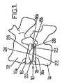
本発明は、脊柱の2つの椎骨12と14の間に配置されることになる椎間板のプロテーゼ10に関する。例えば図1には、脊柱の2つの椎骨12と14の間に本発明のプロテーゼ10が配置された輪郭図が示してある。このタイプのプロテーゼ10は、外傷、病気、老化によって退化した椎間板の代わりに使用することができる。 The present invention relates to an
退化によって2つの椎骨の間に元からあるスペースが変化する可能性がある。元からあるこのスペースが狭くなるといくつかの神経が圧迫され、その結果として痛みが生じる可能性がある。 Degeneration can change the original space between the two vertebrae. As this natural space narrows, some nerves are compressed, resulting in pain.
ところが本発明による椎間板のプロテーゼを利用すると、2つの椎骨の間に元からあるスペースを維持することができる。 However, using the intervertebral disc prosthesis according to the present invention, an original space can be maintained between the two vertebrae.
このプロテーゼにより、2つの椎骨が互いに自然な動きをすることもできるはずである。特に、このプロテーゼにより、一部が人体の胴体または首の回転運動に対応する軸回転運動と、人体の上部または頭の屈曲運動または伸展運動に対応する前方後方運動と、人体の上部または首を傾けることに対応する側方運動が可能になるはずである。 This prosthesis should also allow the two vertebrae to move naturally relative to each other. In particular, this prosthesis can be used to rotate the shaft partly corresponding to the rotational movement of the human torso or neck, forward and backward movement corresponding to the upper part of the human body or the flexion or extension movement of the head, and the upper part or neck of the human body. Lateral movement should be possible in response to tilting.
本発明による椎間板のプロテーゼ10は上部プレート16と下部プレート18を備えている。上部プレート16は上側の椎骨の方を向いた外面16aを備え、下部プレート18は下側の椎骨の方を向いた外面18aを備える。それぞれの外面16a、18aの表面には、歯状突起部(図示せず)が配置されていて、椎骨の中にプレート16、18を固定できるようになっている。 The
上部プレート16と下部プレート18は、それぞれ内面16b、18bも有する。内面は互いに向かい合っていて、前方後方の第1の軸Xに沿って横断する方向に延びるとともに、第1の軸と垂直な第2の軸Yに沿って長手方向に延びていて、中間部材20と接触している。 The
中間部材20は、円形の周辺部23を有する円形底部22を備えている。底部22の上には半円球24が取り付けられている。底部22は下部プレート18の内面18bに可動状態で取り付けられ、半円球24が、上部プレート16の内面16bに設けられた窪み26と協働している。この窪み26は輪郭が球形であるため、中間部材20の半円球24と上部プレート16とをボールジョイント結合することが可能になる。 The
上部プレート16は、クロム-コバルト、またはチタン、またはステンレス鋼といったタイプの材料で実現され、中間部材は、滑り特性が非常に優れた高密度ポリエチレン・タイプのプラスチック材料で実現される。 The
上側の椎骨12に固定された上部プレート16と、下部プレート18によって下側の椎骨14に接続された中間部材20との間のボールジョイント結合により、脊柱の2つの椎骨12と14の間の屈曲運動または伸展運動と、傾ける運動を再現することができる。 Bending between the two
図3に、下部プレート18の内面18bと中間部材20の立面図を示してある。下部プレート18の内面18bには、中間部材20の移動をガイドする繰り抜き部28がある。図3からわかるように、繰り抜き部28は、ほぼ平坦な支持面34と、前縁部28aと、後縁部28bと、前縁部28aと後縁部28bを接続する2つの側方縁部28c、28dとを境界とする「インゲン豆」の形態である。前縁部28aと後縁部28bは前方後方軸(X)に対して対称であり、それぞれ、ほぼ円錐曲線タイプの形状を有する。それを図3では、前方後方軸に沿って後方に開いた放物線の形で描いてある。 FIG. 3 shows an elevation view of the
縁部(28a、28b、28c、28d)が連続した複数の円錐曲線を形成することも可能である。 It is also possible to form a plurality of conical curves in which the edges (28a, 28b, 28c, 28d) are continuous.
図3では、図示した前方後方軸Xは、放物線状の軌跡の対称軸である。放物線状の軌跡は、2つの縁部28aと28bの間の中線に対応する一点鎖線で表わしてある。 In FIG. 3, the illustrated front-rear axis X is a symmetrical axis of a parabolic locus. The parabolic trajectory is represented by a dash-dot line corresponding to the midline between the two
この特徴により、中間部材20は円錐曲線タイプの軌跡(例えば円弧、放物線の一部、双曲線の一部、楕円の一部)、または連続した円錐曲線タイプの軌跡(例えば隣り合った複数の円弧)に沿って移動することができる。そのため中間部材は、2つの椎骨の間の実際の回転運動に非常に近い運動をする。 This feature allows the
図2に示した軌跡は円弧である。 The locus shown in FIG. 2 is an arc.
図3に示した軌跡は放物線であり、デカルト座標で単純化して表わした式は、
y2 = 2px
のタイプである。The trajectory shown in FIG. 3 is a parabola, and the simplified expression in Cartesian coordinates is
y2 = 2px
Of the type.
さらに、2つの側方縁部の間で円錐曲線タイプの軌跡に沿って移動する振幅Dは、中間部材20の底部22の直径の約0.01〜2倍である。そのためさまざまな患者に対応することができ、患者は、実際の運動に近い運動を実現する能力を取り戻すことができる。 Furthermore, the amplitude D moving along the conical curve type trajectory between the two side edges is approximately 0.01 to 2 times the diameter of the bottom 22 of the
さらに、繰り抜き部28は、中間部材20が前方から後方に並進運動できるようにされているため、屈曲運動の際には中間部材が後方に並進運動でき、伸展運動の際には中間部材20が前方に並進運動できる。 Further, since the
前方から後方に向かうこの運動の振幅Aは、軌跡に沿って、患者が誰であるかに応じ、軌跡上の各点においてその点の接線に対して垂直な軸の方向に0.1〜3mmであることが望ましく、0.5〜3mmであることがより好ましい。 The amplitude A of this movement from the front to the back is 0.1-3 mm in the direction of the axis perpendicular to the tangent of that point at each point on the trajectory, depending on who the patient is along the trajectory It is desirable that the thickness is 0.5 to 3 mm.
繰り抜き部28のこの特徴により、特に屈曲と回転が組み合わさった運動の際に自然な椎骨間の接続を再現できるプロテーゼが得られる。 This feature of the
下部プレート18の内面18bに設けられた繰り抜き部28の中を中間部材20の底部22が移動するとき、底部22の周辺部23は、繰り抜き部28の縁部28a、28bと接触する。すると中間部材20の運動は、中間部材20が繰り抜き部28の境界となる縁部28a、28bに沿って転がることによって得られる。その結果、滑りだけによる接触のときのような摩擦による早すぎる摩耗現象が避けられる。中間部材20が移動する際の摩擦を抑制し、その結果として早すぎる摩耗を抑制するため、繰り抜き部28の支持面を処理してその滑り特性を改善する場合(例えば、多鏡面処理 traitement polymiroir、または、窒化物コーティング)と、底部の底を高分子量のポリエチレンにする場合に、底部22の底と繰り抜き部28の支持面の間の滑りが得られよう。 When the
例えば繰り抜き部の縁部が円弧の形状である場合には、底部22の周辺部23の各点はサイクロイド曲線を描くであろう。 For example, when the edge of the punched-out part has an arc shape, each point on the
図4に示した本発明の一変形例によると、中間部材の底部は、貫通するか貫通していない複数の穴32を有する円環部30を備えている。そのため繰り抜き部28の縁部28a、28bと円環部30の間の衝撃が緩和される。実際には、円環部30は、高分子量のポリエチレン・タイプの材料、または優れたダンパ特性を有する生体適合性のあるまったく別の材料でできている。円環部30は、穴32が存在していることで、中間部材が繰り抜き部28の縁部28a、28bにぶつかったときに接触を和らげるのに十分な変形能力を有する。そのため患者が感じる関節部の痛みを減らすことができる。 According to one modification of the present invention shown in FIG. 4, the bottom portion of the intermediate member includes an
Claims (8)
Translated fromJapanese上部プレート(16)と、
ほぼ平坦な支持面を構成する下部プレート(18)と、
周辺部(23)を構成し半円球(24)を載置した底部(22)を有する中間部材(20)を具備していて、
前記上部プレートは、前記半円球と相補的な窪みを構成し、前記上部プレート(16)と前記中間部材(20)との間でボールジョイント結合となるように前記半円球と接触しており、
前記中間部材の底部は、前記支持面と接触しており、
前記下部プレート(18)は、互いに向かい合った前縁部と後縁部(28a、28b)の2つの縁部を有するガイド(28)を構成していて、両方の縁部の間がほぼ一定の距離であってその両方の縁部の間に前記中間部材を保持しており、
前記半円球の底部の周辺部は、前記前縁部と前記後縁部(28a、28b)の少なくとも一方と接触している椎間板のプロテーゼにおいて、
前記周辺部は円形であり、前記周辺部は、前記中間部材が前記前縁部と前記後縁部(28a、28b)に沿って転がることによって移動できるように形成されていることを特徴とする椎間板のプロテーゼ。Intervertebral disc prosthesis
The upper plate (16),
A lower plate (18) comprising a substantially flat support surface;
Comprising an intermediate member (20) having a bottom part (22) on which a peripheral part (23) and a hemisphere (24) are placed;
The upper plate forms a recess complementary to the hemisphere, and is in contact with the hemisphere so as to form a ball joint connection between the upper plate (16) and the intermediate member (20). And
The bottom of the intermediate member is in contact with the support surface;
The lower plate (18) constitutes a guide (28) having two edges, a front edge and a rear edge (28a, 28b) facing each other, and the gap between both edges is substantially constant. Holding the intermediate member at a distance and between its edges,
In the prosthesis of the intervertebral disc in which the periphery of the bottom of the hemisphere is in contact with at least one of the front edge and the rear edge (28a, 28b),
The peripheral portion is circular, and the peripheral portion is formed such that the intermediate member can move by rolling along the front edge portion and the rear edge portion (28a, 28b). Intervertebral disc prosthesis.
Applications Claiming Priority (3)
| Application Number | Priority Date | Filing Date | Title |
|---|---|---|---|
| FR0504510 | 2005-05-03 | ||
| FR0504510AFR2885294B1 (en) | 2005-05-03 | 2005-05-03 | INTERVERTEBRAL DISC PROSTHESIS |
| PCT/FR2006/000982WO2006117474A1 (en) | 2005-05-03 | 2006-05-02 | Intervertebral disc prosthesis |
Publications (2)
| Publication Number | Publication Date |
|---|---|
| JP2008539845Atrue JP2008539845A (en) | 2008-11-20 |
| JP4801145B2 JP4801145B2 (en) | 2011-10-26 |
Family
ID=35462122
Family Applications (1)
| Application Number | Title | Priority Date | Filing Date |
|---|---|---|---|
| JP2008509469AActiveJP4801145B2 (en) | 2005-05-03 | 2006-05-02 | Intervertebral disc prosthesis |
Country Status (10)
| Country | Link |
|---|---|
| US (1) | US7887590B2 (en) |
| EP (1) | EP1877011B1 (en) |
| JP (1) | JP4801145B2 (en) |
| KR (1) | KR101303338B1 (en) |
| CN (1) | CN101170968B (en) |
| BR (1) | BRPI0610991B8 (en) |
| CA (1) | CA2607717A1 (en) |
| FR (1) | FR2885294B1 (en) |
| MX (1) | MX2007013678A (en) |
| WO (1) | WO2006117474A1 (en) |
Families Citing this family (21)
| Publication number | Priority date | Publication date | Assignee | Title |
|---|---|---|---|---|
| US8029574B2 (en) | 2006-11-07 | 2011-10-04 | Biomedflex Llc | Prosthetic knee joint |
| US9005307B2 (en) | 2006-11-07 | 2015-04-14 | Biomedflex, Llc | Prosthetic ball-and-socket joint |
| US7905919B2 (en) | 2006-11-07 | 2011-03-15 | Biomedflex Llc | Prosthetic joint |
| US8512413B2 (en) | 2006-11-07 | 2013-08-20 | Biomedflex, Llc | Prosthetic knee joint |
| US8308812B2 (en) | 2006-11-07 | 2012-11-13 | Biomedflex, Llc | Prosthetic joint assembly and joint member therefor |
| US8070823B2 (en) | 2006-11-07 | 2011-12-06 | Biomedflex Llc | Prosthetic ball-and-socket joint |
| US7914580B2 (en) | 2006-11-07 | 2011-03-29 | Biomedflex Llc | Prosthetic ball-and-socket joint |
| US20110166671A1 (en) | 2006-11-07 | 2011-07-07 | Kellar Franz W | Prosthetic joint |
| WO2008058205A1 (en) | 2006-11-07 | 2008-05-15 | Biomedflex, Llc | Medical implants |
| WO2008088777A2 (en)* | 2007-01-12 | 2008-07-24 | Synthes Usa, Llc | Modular intervertebral implant |
| DE102007024262B4 (en)* | 2007-05-23 | 2017-01-26 | Janos Borgulya | Intervertebral disc prosthesis and instrument cluster with a disc prosthesis |
| US8216314B2 (en)* | 2008-02-13 | 2012-07-10 | Marc Richelsoph | Distractable spinal implant assembly |
| CN104068925B (en)* | 2008-03-26 | 2017-07-14 | 斯恩蒂斯有限公司 | For the universal anchor by physical attachment on bone tissue |
| CN102046111A (en) | 2008-06-05 | 2011-05-04 | 斯恩蒂斯有限公司 | Articulating disc implant |
| US8882838B2 (en)* | 2008-06-05 | 2014-11-11 | DePuy Synthes Products, LLC | Articulating disc implant |
| US9060808B2 (en) | 2008-12-05 | 2015-06-23 | DePuy Synthes Products, Inc. | Anchor-in-anchor system for use in bone fixation |
| JP5759900B2 (en) | 2008-12-05 | 2015-08-05 | ジンテス ゲゼルシャフト ミット ベシュレンクテル ハフツング | Anchor-in-anchor system for use in bone fixation |
| US20110112644A1 (en)* | 2009-11-12 | 2011-05-12 | Zilberstein Boris | Disc prosthetic implant device |
| US8998991B2 (en)* | 2011-02-23 | 2015-04-07 | Globus Medical, Inc. | Six degree spine stabilization devices and methods |
| CN102648879A (en)* | 2011-02-24 | 2012-08-29 | 四川大学华西医院 | Artificial intervertebral disc |
| US10881523B2 (en)* | 2017-07-05 | 2021-01-05 | Keith L Doty | Motion preserving spinal total disc replacement apparatus, method and related systems |
Citations (8)
| Publication number | Priority date | Publication date | Assignee | Title |
|---|---|---|---|---|
| JPH0552218B2 (en)* | 1984-09-04 | 1993-08-04 | Funboruto Uniberujiteeto Tsuu | |
| US5425773A (en)* | 1992-01-06 | 1995-06-20 | Danek Medical, Inc. | Intervertebral disk arthroplasty device |
| US6368350B1 (en)* | 1999-03-11 | 2002-04-09 | Sulzer Spine-Tech Inc. | Intervertebral disc prosthesis and method |
| US6517580B1 (en)* | 2000-03-03 | 2003-02-11 | Scient'x Societe A Responsabilite Limited | Disk prosthesis for cervical vertebrae |
| DE202004009542U1 (en)* | 2004-06-16 | 2004-08-12 | Aesculap Ag & Co. Kg | Artificial intervertebral disk, comprising core with intensely curved upper and less curved lower surface |
| WO2005007038A1 (en)* | 2003-07-22 | 2005-01-27 | Synthes Gmbh | Articulated endoprosthesis |
| DE10330698A1 (en)* | 2003-07-08 | 2005-02-03 | Aesculap Ag & Co. Kg | Intervertebral implant |
| DE10339170A1 (en)* | 2003-08-22 | 2005-03-24 | Aesculap Ag & Co. Kg | Intervertebral implant useful as replacement for intervertebral disk, includes upper and lower support bodies that are supported pivotably in relation to one another via saddle joint |
Family Cites Families (9)
| Publication number | Priority date | Publication date | Assignee | Title |
|---|---|---|---|---|
| EP0566810B1 (en)* | 1992-04-21 | 1996-08-14 | SULZER Medizinaltechnik AG | Artificial spinal disc |
| DE60028370T2 (en)* | 1999-04-21 | 2007-05-03 | Howmedica Osteonics Corp. | METHOD FOR THE PRODUCTION OF A SELECTIVELY NETWORKED MEDICAL PROSTHESIS FROM POLYETHYLENE, AND A PROSTHESIS MANUFACTURED THEREOF |
| FR2824261B1 (en)* | 2001-05-04 | 2004-05-28 | Ldr Medical | INTERVERTEBRAL DISC PROSTHESIS AND IMPLEMENTATION METHOD AND TOOLS |
| CN100574728C (en)* | 2002-03-30 | 2009-12-30 | 无限整形外科有限公司 | Intervertebral disc replacement device and system |
| US6793678B2 (en)* | 2002-06-27 | 2004-09-21 | Depuy Acromed, Inc. | Prosthetic intervertebral motion disc having dampening |
| AU2003287370B2 (en)* | 2002-10-31 | 2009-05-07 | Zimmer Spine, Inc. | Movable disc implant |
| US7105024B2 (en)* | 2003-05-06 | 2006-09-12 | Aesculap Ii, Inc. | Artificial intervertebral disc |
| EP1649566A4 (en)* | 2003-06-27 | 2007-08-15 | Applied Materials Inc | LASER SYSTEM WITH QUANTIC PULSE POINTS HAVING LOW INSTABILITY |
| DE20315611U1 (en)* | 2003-10-08 | 2003-12-11 | Aesculap Ag & Co. Kg | Intervertebral implant |
- 2005
- 2005-05-03FRFR0504510Apatent/FR2885294B1/ennot_activeExpired - Lifetime
- 2006
- 2006-05-02BRBRPI0610991Apatent/BRPI0610991B8/enactiveIP Right Grant
- 2006-05-02WOPCT/FR2006/000982patent/WO2006117474A1/enactiveApplication Filing
- 2006-05-02USUS11/913,336patent/US7887590B2/enactiveActive
- 2006-05-02MXMX2007013678Apatent/MX2007013678A/enactiveIP Right Grant
- 2006-05-02JPJP2008509469Apatent/JP4801145B2/enactiveActive
- 2006-05-02EPEP06764584.6Apatent/EP1877011B1/enactiveActive
- 2006-05-02CACA002607717Apatent/CA2607717A1/ennot_activeAbandoned
- 2006-05-02KRKR1020077028259Apatent/KR101303338B1/enactiveActive
- 2006-05-02CNCN2006800150661Apatent/CN101170968B/enactiveActive
Patent Citations (8)
| Publication number | Priority date | Publication date | Assignee | Title |
|---|---|---|---|---|
| JPH0552218B2 (en)* | 1984-09-04 | 1993-08-04 | Funboruto Uniberujiteeto Tsuu | |
| US5425773A (en)* | 1992-01-06 | 1995-06-20 | Danek Medical, Inc. | Intervertebral disk arthroplasty device |
| US6368350B1 (en)* | 1999-03-11 | 2002-04-09 | Sulzer Spine-Tech Inc. | Intervertebral disc prosthesis and method |
| US6517580B1 (en)* | 2000-03-03 | 2003-02-11 | Scient'x Societe A Responsabilite Limited | Disk prosthesis for cervical vertebrae |
| DE10330698A1 (en)* | 2003-07-08 | 2005-02-03 | Aesculap Ag & Co. Kg | Intervertebral implant |
| WO2005007038A1 (en)* | 2003-07-22 | 2005-01-27 | Synthes Gmbh | Articulated endoprosthesis |
| DE10339170A1 (en)* | 2003-08-22 | 2005-03-24 | Aesculap Ag & Co. Kg | Intervertebral implant useful as replacement for intervertebral disk, includes upper and lower support bodies that are supported pivotably in relation to one another via saddle joint |
| DE202004009542U1 (en)* | 2004-06-16 | 2004-08-12 | Aesculap Ag & Co. Kg | Artificial intervertebral disk, comprising core with intensely curved upper and less curved lower surface |
Also Published As
| Publication number | Publication date |
|---|---|
| CA2607717A1 (en) | 2006-11-09 |
| MX2007013678A (en) | 2008-04-08 |
| EP1877011A1 (en) | 2008-01-16 |
| BRPI0610991B1 (en) | 2017-06-27 |
| CN101170968B (en) | 2010-08-25 |
| WO2006117474A1 (en) | 2006-11-09 |
| FR2885294B1 (en) | 2008-04-04 |
| BRPI0610991A2 (en) | 2010-08-10 |
| KR101303338B1 (en) | 2013-09-03 |
| US7887590B2 (en) | 2011-02-15 |
| US20080243253A1 (en) | 2008-10-02 |
| CN101170968A (en) | 2008-04-30 |
| EP1877011B1 (en) | 2014-08-27 |
| JP4801145B2 (en) | 2011-10-26 |
| KR20080014825A (en) | 2008-02-14 |
| FR2885294A1 (en) | 2006-11-10 |
| BRPI0610991B8 (en) | 2021-06-22 |
Similar Documents
| Publication | Publication Date | Title |
|---|---|---|
| JP4801145B2 (en) | Intervertebral disc prosthesis | |
| KR100701991B1 (en) | Intervertebral Implant | |
| JP4920602B2 (en) | Shock absorbing disc prosthesis | |
| US20050080488A1 (en) | Intervertebral implant | |
| US8821576B2 (en) | Intervertebral disk prosthesis | |
| JP5209493B2 (en) | Anatomical intervertebral spacer and its applications | |
| JP4990296B2 (en) | Intervertebral disk replacement device | |
| JP2005537053A (en) | Intervertebral implant with a three-part joint | |
| JP5202341B2 (en) | Artificial disc | |
| US20100076558A1 (en) | Prosthetic Disc For Intervertebral Insertion | |
| JP2008508035A (en) | Intervertebral prosthesis with metal core | |
| US20070255418A1 (en) | Ball-Type Triple-Joint Implant System for Upper or Lower Limbs | |
| CN101056598A (en) | Interdiscal prosthesis with motion-fitting edges for the lumbar and cervical spine | |
| JP2006515194A (en) | Intervertebral disc or intervertebral disc prosthesis | |
| JP2007508859A (en) | Disc replacement device | |
| JP4980223B2 (en) | Lumbar and cervical disc prosthesis with physiological movement | |
| NZ550176A (en) | Intervertebral disc prosthesis or artificial vertebral body | |
| EP2259756B1 (en) | Intervertebral disk prosthesis notably for cervical vertebrae | |
| KR20130097206A (en) | Compliant implant | |
| JPH11137585A (en) | Artificial vertebral disk | |
| KR102484143B1 (en) | Artificial disc | |
| JP2012517871A (en) | Intervertebral disc prosthesis | |
| AU2005229466B2 (en) | Artificial intervertebral disk | |
| CN119925046B (en) | Artificial intervertebral disc prosthesis | |
| CN119112448A (en) | Flexible artificial vertebral body for spine |
Legal Events
| Date | Code | Title | Description |
|---|---|---|---|
| A621 | Written request for application examination | Free format text:JAPANESE INTERMEDIATE CODE: A621 Effective date:20090217 | |
| A977 | Report on retrieval | Free format text:JAPANESE INTERMEDIATE CODE: A971007 Effective date:20100930 | |
| A131 | Notification of reasons for refusal | Free format text:JAPANESE INTERMEDIATE CODE: A131 Effective date:20101012 | |
| A521 | Request for written amendment filed | Free format text:JAPANESE INTERMEDIATE CODE: A523 Effective date:20110107 | |
| A131 | Notification of reasons for refusal | Free format text:JAPANESE INTERMEDIATE CODE: A131 Effective date:20110412 | |
| A521 | Request for written amendment filed | Free format text:JAPANESE INTERMEDIATE CODE: A523 Effective date:20110601 | |
| TRDD | Decision of grant or rejection written | ||
| A01 | Written decision to grant a patent or to grant a registration (utility model) | Free format text:JAPANESE INTERMEDIATE CODE: A01 Effective date:20110705 | |
| A01 | Written decision to grant a patent or to grant a registration (utility model) | Free format text:JAPANESE INTERMEDIATE CODE: A01 | |
| A61 | First payment of annual fees (during grant procedure) | Free format text:JAPANESE INTERMEDIATE CODE: A61 Effective date:20110804 | |
| FPAY | Renewal fee payment (event date is renewal date of database) | Free format text:PAYMENT UNTIL: 20140812 Year of fee payment:3 | |
| R150 | Certificate of patent or registration of utility model | Ref document number:4801145 Country of ref document:JP Free format text:JAPANESE INTERMEDIATE CODE: R150 Free format text:JAPANESE INTERMEDIATE CODE: R150 | |
| R250 | Receipt of annual fees | Free format text:JAPANESE INTERMEDIATE CODE: R250 | |
| R250 | Receipt of annual fees | Free format text:JAPANESE INTERMEDIATE CODE: R250 | |
| R250 | Receipt of annual fees | Free format text:JAPANESE INTERMEDIATE CODE: R250 | |
| R250 | Receipt of annual fees | Free format text:JAPANESE INTERMEDIATE CODE: R250 | |
| R250 | Receipt of annual fees | Free format text:JAPANESE INTERMEDIATE CODE: R250 | |
| R250 | Receipt of annual fees | Free format text:JAPANESE INTERMEDIATE CODE: R250 | |
| R250 | Receipt of annual fees | Free format text:JAPANESE INTERMEDIATE CODE: R250 | |
| R250 | Receipt of annual fees | Free format text:JAPANESE INTERMEDIATE CODE: R250 | |
| R250 | Receipt of annual fees | Free format text:JAPANESE INTERMEDIATE CODE: R250 | |
| R250 | Receipt of annual fees | Free format text:JAPANESE INTERMEDIATE CODE: R250 | |
| R250 | Receipt of annual fees | Free format text:JAPANESE INTERMEDIATE CODE: R250 | |
| R250 | Receipt of annual fees | Free format text:JAPANESE INTERMEDIATE CODE: R250 |