JP2008536563A - Extraction prevention mechanism for implant fasteners - Google Patents
Extraction prevention mechanism for implant fastenersDownload PDFInfo
- Publication number
- JP2008536563A JP2008536563AJP2008506620AJP2008506620AJP2008536563AJP 2008536563 AJP2008536563 AJP 2008536563AJP 2008506620 AJP2008506620 AJP 2008506620AJP 2008506620 AJP2008506620 AJP 2008506620AJP 2008536563 AJP2008536563 AJP 2008536563A
- Authority
- JP
- Japan
- Prior art keywords
- fastener
- hole
- implant
- lumen
- retention mechanism
- Prior art date
- Legal status (The legal status is an assumption and is not a legal conclusion. Google has not performed a legal analysis and makes no representation as to the accuracy of the status listed.)
- Pending
Links
- 230000007246mechanismEffects0.000titleclaimsabstractdescription117
- 239000007943implantSubstances0.000titleclaimsdescription53
- 238000000605extractionMethods0.000titledescription2
- 230000002265preventionEffects0.000title1
- 230000014759maintenance of locationEffects0.000claimsabstractdescription78
- 210000000988bone and boneAnatomy0.000claimsabstractdescription73
- 238000003780insertionMethods0.000claimsabstractdescription11
- 230000037431insertionEffects0.000claimsabstractdescription11
- 238000000034methodMethods0.000claimsdescription6
- 230000000149penetrating effectEffects0.000claims1
- 230000000717retained effectEffects0.000abstractdescription4
- 238000012986modificationMethods0.000description3
- 230000004048modificationEffects0.000description3
- 238000002513implantationMethods0.000description2
- 239000000463materialSubstances0.000description2
- 230000008531maintenance mechanismEffects0.000description1
- 230000000399orthopedic effectEffects0.000description1
- 125000006850spacer groupChemical group0.000description1
- 238000001356surgical procedureMethods0.000description1
Images


Classifications
- A—HUMAN NECESSITIES
- A61—MEDICAL OR VETERINARY SCIENCE; HYGIENE
- A61B—DIAGNOSIS; SURGERY; IDENTIFICATION
- A61B17/00—Surgical instruments, devices or methods
- A61B17/56—Surgical instruments or methods for treatment of bones or joints; Devices specially adapted therefor
- A61B17/58—Surgical instruments or methods for treatment of bones or joints; Devices specially adapted therefor for osteosynthesis, e.g. bone plates, screws or setting implements
- A61B17/68—Internal fixation devices, including fasteners and spinal fixators, even if a part thereof projects from the skin
- A61B17/80—Cortical plates, i.e. bone plates; Instruments for holding or positioning cortical plates, or for compressing bones attached to cortical plates
- A61B17/8033—Cortical plates, i.e. bone plates; Instruments for holding or positioning cortical plates, or for compressing bones attached to cortical plates having indirect contact with screw heads, or having contact with screw heads maintained with the aid of additional components, e.g. nuts, wedges or head covers
- A61B17/8047—Cortical plates, i.e. bone plates; Instruments for holding or positioning cortical plates, or for compressing bones attached to cortical plates having indirect contact with screw heads, or having contact with screw heads maintained with the aid of additional components, e.g. nuts, wedges or head covers wherein the additional element surrounds the screw head in the plate hole
Landscapes
- Health & Medical Sciences (AREA)
- Orthopedic Medicine & Surgery (AREA)
- Surgery (AREA)
- Life Sciences & Earth Sciences (AREA)
- Heart & Thoracic Surgery (AREA)
- Nuclear Medicine, Radiotherapy & Molecular Imaging (AREA)
- Engineering & Computer Science (AREA)
- Biomedical Technology (AREA)
- Neurology (AREA)
- Medical Informatics (AREA)
- Molecular Biology (AREA)
- Animal Behavior & Ethology (AREA)
- General Health & Medical Sciences (AREA)
- Public Health (AREA)
- Veterinary Medicine (AREA)
- Surgical Instruments (AREA)
- Prostheses (AREA)
Abstract
Translated fromJapaneseDescription
Translated fromJapanese骨プレート、及び他のインプラントを、骨または骨セグメントの隣接する骨部分に使用して、そうした骨部分を安定化させることができるものである。 Bone plates, and other implants, can be used on adjacent bone portions of a bone or bone segment to stabilize such bone portions.
インプラントを骨部分に係合させるために、留め具を使用することができる。留め具がインプラントから抜け出て、その下にある骨から抜け出ることを防止するために、骨留め具に隣接して、またはその周りでインプラントに係合させる様々な保持装置が開発されてきている。いくつかの保持装置は、骨スクリューが移動して保持装置と接触すると、骨スクリューと干渉する止めねじ、ワッシャ、アーム、またはフラップの形である。これらの保持装置は、留め具がインプラントから抜け出ることを防止するように、留め具を阻止する。 A fastener can be used to engage the implant with the bone portion. Various retention devices have been developed that engage the implant adjacent to or around the bone fastener to prevent the fastener from slipping out of the implant and from the underlying bone. Some retention devices are in the form of set screws, washers, arms, or flaps that interfere with the bone screw as the bone screw moves and contacts the retention device. These retaining devices prevent the fasteners from preventing the fasteners from exiting the implant.
一態様によれば、骨留め具がインプラントの穴を貫通して配置される際に、留め具挿入の間、留め具のインプラントに対する多軸性能を保持しながら、骨留め具をインプラントに係合させる保持機構が提供される。留め具の頭部がインプラントに隣接して配置されると、この頭部は、任意選択で保持機構内に受けられ、その保持機構を拡張させて、保持機構をインプラントと係止係合にしっかりと係合させ、骨留め具をインプラントに対して定位置に係止させることができる。別の形態では、骨留め具のインプラントに対する多軸配置性能は、骨留め具が最終的に保持機構内に配置されたときに保持されるか、または少なくとも部分的に保持される。 According to one aspect, when the bone fastener is placed through the hole in the implant, the bone fastener engages the implant while retaining the multiaxial performance of the fastener against the implant during fastener insertion. A holding mechanism is provided. When the head of the fastener is placed adjacent to the implant, the head is optionally received within the retention mechanism and expands the retention mechanism to secure the retention mechanism in locking engagement with the implant. And the bone fastener can be locked in place relative to the implant. In another form, the multi-axial placement performance of the bone fastener relative to the implant is retained or at least partially retained when the bone fastener is ultimately disposed within the retention mechanism.
別の態様によれば、中を貫通して配置される骨留め具のねじ付き輪郭と合致する雌ねじ付き内腔を含む、インプラント留め具用の保持機構が提供される。別の形態では、この内腔は、骨留め具が保持機構を貫通してねじ付けられる際に、骨留め具のねじの巻き間に嵌合するように寸法設定される。 According to another aspect, a retention mechanism for an implant fastener is provided that includes an internally threaded lumen that matches a threaded contour of a bone fastener disposed therethrough. In another form, the lumen is sized to fit between the turns of the bone fastener as the bone fastener is threaded through the retention mechanism.
他の態様では、骨留め具は、骨留め具頭部の、縦軸に直交する外側寸法よりも大きい、骨留め具の縦軸に直交する外側寸法を有するねじ付き輪郭を含む。インプラントに結合される保持機構は、骨留め具がその中を貫通して通ることが可能となるように構成される。 In another aspect, the bone fastener includes a threaded profile having an outer dimension perpendicular to the longitudinal axis of the bone fastener that is greater than an outer dimension perpendicular to the longitudinal axis of the bone fastener head. The retention mechanism coupled to the implant is configured to allow the bone fastener to pass therethrough.
別の態様では、保持機構は、骨留め具がその下にある骨構造にねじ係合される際に、骨留め具のインプラントに対する多軸配置性能を保持しながら、骨留め具をインプラントに対して保持する。 In another aspect, the retention mechanism holds the bone fastener relative to the implant while retaining the multiaxial placement performance of the bone fastener relative to the implant when the bone fastener is threaded into the underlying bone structure. Hold.
別の態様によれば、骨留め具を受けるための穴を有するインプラントが提供される。この穴は、インプラントの上側表面と下側表面との間に延びる凹状側壁を含み、したがって、開口の最大寸法は、開口の、インプラント上側表面と下側表面との間の中央部分に沿っている。このインプラントは、穴に隣接し、インプラントの上側または下側表面の一方から穴の中央部分まで延びる対向する通路をさらに含む。 According to another aspect, an implant having a hole for receiving a bone fastener is provided. The hole includes a concave sidewall extending between the upper and lower surfaces of the implant, so the maximum dimension of the opening is along the central portion of the opening between the upper and lower implant surfaces . The implant further includes an opposing passage adjacent to the bore and extending from one of the upper or lower surface of the implant to the central portion of the bore.
他の態様によれば、インプラント穴内で骨留め具を保持するように、インプラント穴の凹状表面輪郭に合致する凸状外側壁面輪郭を備えた保持機構が提供される。インプラント穴に隣接する通路によって、保持機構が、インプラント穴内でのその通常の留め具受け位置に対して90度回転した挿入向きにある間に、インプラント穴内に挿入されることが可能となる。この回転向きでは、保持機構の壁は、通路と位置が並ぶ。保持機構は、この向きにおいて、保持機構の外側表面の最大寸法が、インプラント穴の最大寸法と位置が並ぶまで、通路を通ってインプラント穴内に誘導される。次いで、保持機構は90度回転し、その結果、この保持機構は、インプラント穴内に据えられ、捕捉されることになる。保持機構とインプラント穴との合致した凹凸輪郭によって、保持機構がその留め具受け向きにある間、この保持機構がインプラント穴から遠位に、または近位に通り抜けることが防止される。この保持機構は、その外側表面がインプラント穴に隣接した対向する通路と位置が並ぶように、その挿入向きまで90度回転させることによって、取り外されることができる。 According to another aspect, a retention mechanism is provided having a convex outer wall contour that matches the concave surface contour of the implant hole to retain the bone fastener within the implant hole. The passage adjacent to the implant hole allows the retention mechanism to be inserted into the implant hole while in the insertion orientation rotated 90 degrees relative to its normal fastener receiving position within the implant hole. In this rotational direction, the wall of the holding mechanism is aligned with the passage. In this orientation, the retention mechanism is guided through the passage and into the implant hole until the maximum dimension of the outer surface of the retention mechanism is aligned with the maximum dimension of the implant hole. The retention mechanism is then rotated 90 degrees so that it is placed and captured within the implant hole. The matched contoured contour of the retention mechanism and the implant hole prevents the retention mechanism from passing distally or proximally from the implant hole while the retention mechanism is in its fastener receiving orientation. The retaining mechanism can be removed by rotating it 90 degrees to its insertion orientation so that its outer surface is aligned with the opposing passage adjacent to the implant hole.
本発明の上記その他の態様はまた、以下の説明から明白となるであろう。 These and other aspects of the invention will also be apparent from the following description.
次に、本発明の原理の理解を促すために、図面に示した実施形態を参照し、特定の用語を使用して同実施形態を説明する。とはいえ、それによって本発明の範囲が限定されるものではないことを理解されたい。例示の装置におけるどのようなかかる変更形態及びさらなる改変形態も、また、本明細書に記載の本発明の原理のかかるさらなる応用も、本発明が関連する技術分野の当業者には、通常想起されるものとして企図される。 To facilitate an understanding of the principles of the present invention, reference will now be made to the embodiment illustrated in the drawings and specific language will be used to describe the same. Nevertheless, it should be understood that this does not limit the scope of the invention. Any such modifications and further modifications in the exemplary apparatus, as well as such further applications of the principles of the invention described herein, will generally be conceived by those skilled in the art to which the invention pertains. Is intended.
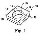
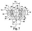
図1及び図7には、骨インプラント10の一部分が、上側表面15と下側表面16との間の開口に延びる穴(ホール)14を有するプレート12の形で示される。本明細書では、下側表面16とは、プレート12が取り付けられるべきその下の骨構造に接して、または隣接して配置可能なプレート12の表面を指す。穴14は、上側表面15と下側表面16との間に延びる壁面18によって画定される。例示の実施形態の壁面18は、凹状に湾曲しており、上側表面15と下側表面16との間の、穴14の中央部分19に沿って位置するどの位置においても、最大開口寸法20を画定する。穴14の、上側及び下側表面15、16に隣接する寸法は、図7に示すように保持機構30がその留め具受け向きにあるときに、保持機構30が開口14を貫通して遠位に、または近位に通り抜けることを防止するように、最大穴寸法20よりも小さくなっている。 1 and 7, a portion of the
プレート12は、その中に穴14に隣接して形成された受け通路26をさらに含み、この受け通路は、保持機構30を穴14内に配置しやすくするように適合される。通路26は、穴14の周りで互いに対向して配置され、上側表面15から穴14の中央部分19まで延びる。通路26は、プレート12内に陥凹して、穴14の壁面18に不連続部を形成する。これらの不連続部によって、穴14の残る部分の周りの壁18によって画定される開口寸法よりも大きい開口寸法がもたらされる。
図2及び図6は、プレート12の穴14内に配置可能な保持機構30を示す。保持機構30は、穴14及び保持機構30を貫通して配置されることになる骨留め具60(図7及び8)を受けて、プレート12をその下にある骨構造に固定する。保持機構30は、プレートと骨留め具との間に延び、プレートに係合して、留め具がプレートから抜け出ることを防止する。例示の実施形態では、保持機構30は、外側表面32と、上側端部40と下側端部42との間に延びる内腔(ボア、孔)34とを含む円筒状(筒状)の本体を備えたブッシュの形である。内腔34は、少なくとも一部には、雌ねじ付き輪郭36が中に形成された内側壁面44によって画定される。上側及び下側端部40、42は、保持機構30が穴14内に配置されたときに、隣接するプレート12の上側及び下側表面15、16に対して同一平面でも、または陥凹していてもよい。別の実施形態では、端部40、42の一方、または両方とも、隣接する上側または下側表面15、16から外方に突き出す。内腔34は、そこを貫通する留め具を配置しやすくするように、上側及び下側端部40、42に隣接してフレア状に広げられてもよい。 2 and 6 show a
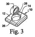
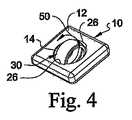
図3〜図5は、保持機構30をプレート穴14内に配置する一技術の各ステップを示す。図7に示すように、穴14は、留め具60と保持機構30の内腔34とが、穴14内に配置されたときにそこに沿って位置が並ぶ中央軸線61を含む。図3では、保持機構30は、挿入向きまで90度回転し、したがって、内腔34は、軸線61に対して横向きに向いている。保持機構30は、この挿入向きで穴14内に誘導され、したがって、外側表面32は通路26内に受けられる。保持機構30は、外側表面32が、壁面18の通路26の終端部に沿って、またはそこに隣接して壁面18と接触する結果、保持機構30がもはや進むことができなくなるまで、通路26を穴14内へと遠位に進む。次いで、保持機構30は、図4の矢印50によって示すように回転し、図5に示す留め具受け向きとなることができる。留め具受け向きでは、内腔34は、中央軸線61と概ね位置が並び、骨留め具60を受けるように、プレート12の上側及び下側表面15、16に向かって開口する。保持機構30は、留め具の、穴14内での変動可能な角度での配置に対応するように、穴14内で回動することができるが、固定係合もまた企図される。 3-5 illustrate the steps of one technique for placing the
保持機構30を挿入するための他の技術もまた企図される。例えば、保持機構は、挿入のために、収縮、またはその他の形で寸法が低減した形状で配置もしくは形成され、その後、プレート穴内に配置するために解放または拡張されることができる。保持機構30はまた、プレート穴内に圧力嵌めされてもよい。さらに別の形態では、保持機構30は、プレート穴内で互いに組み立てられる、または配置される多数の構成要素として設けられてもよい。 Other techniques for inserting the
保持機構30と、プレート12の穴14を画定する壁面18との間の境界面は、互いに近接した関係で配置されるように形成された曲線表面として示される。隣接する表面同士には、曲線表面、直線表面、または曲線表面と直線表面の組合せによって画定された凹凸表面、球形表面、角表面、ならびに少なくとも留め具60が貫通して配置されたときに、保持機構30をプレート12と係合した状態で適切に維持する他のどのような表面形状及び表面構成も含めて、様々な形態が企図される。 The interface between the
保持機構30が、その留め具受け向きでプレート穴14内に配置された後、骨留め具60は、保持機構30中を進んで、プレート12をその下にある骨構造に固定することができる。一実施形態では、留め具60は、ねじ付き輪郭64が沿った軸部62と、軸部62の近位端に拡大頭部66とを含む骨スクリューである。例示の実施形態では、頭部66は、留め具60の縦軸に直交する幅72を含み、この幅72は、ねじ付き輪郭64の外側頂部間のねじ幅70よりも小さい。別の実施形態では、頭部66の幅72は、ねじ幅70と同じか、またはそれよりも大きい。 After the
使用時には、保持機構30は、上記で論じた技術のいずれかを用いてプレート12の穴14内に配置される。留め具60は、穴14の上から位置が並べられ、したがって、留め具60の遠位端は、保持機構30の内腔34内に挿入されることができる。留め具60は、保持機構30中を、ねじ付き輪郭64が保持機構30の雌ねじ付き輪郭36とねじ係合してねじ進むことができる。このように係合されると、保持機構30は、矢印50の方向に十分に回転して、外側表面32の通路26と位置が並ぶことが防止される。したがって、保持機構30は、プレート穴14内で留め具60と共に移動不可能に捕捉される。さらに、保持機構30は、留め具60が、頭部66が内腔34内にある状態で据えられていないときでも、留め具60をプレート12に対して軸線方向に拘束する。保持機構30は、留め具60がプレート10を貫通して配置され、その下にある骨構造内に打ち込まれる際に、留め具60の多角度配置性能を可能とするように、穴14内で回動することができる。 In use, the
留め具60は、頭部66が内腔34内に、保持機構30の内側壁面44と接触して受けられるまで、図8の矢印52によって示すようにその下にある骨構造内にさらに打ち込まれることができる。留め具60の挿入の間、保持機構30が回転することを防止するために、保持機構30は、その回転を防止する打込み器具または第2の器具によって係合されることができる。保持機構30は、かかる係合を容易にする凹部または他の機構(feature)を備えることができる。保持機構30はまた、留め具挿入の間、その位置を維持するように拡張してプレート穴と係合することもできる。 The
頭部66の幅72は、内側壁面44によって形成される開口に対して、保持機構30を拡張させ、その結果、外側表面32がプレート12の壁面18と接触するように寸法設定されることができる。保持機構30の拡張は、内側壁面44と外側表面32との間に延びるスロット(溝、細長穴、溝穴)38によって促進される。 The
雌ねじ付き輪郭36を設けることによって、ねじ付き輪郭64の幅70を、幅70が内腔34中に嵌合するように求められた場合よりも大きくすることが可能となる。ねじ付き輪郭64によって、プレート10内の穴14の寸法が最小限に抑えられ、プレート10の相対的な材料低減を低減させ、強度の増大を実現し、かつ/または、相対的な強度の損失なく、プレートの寸法低減を可能としながら、骨物質内へのより大きいてこ作用(purchase)が実現される。 By providing the female threaded
別の実施形態では、雌ねじ付き輪郭のない保持機構30が提供される。ここではむしろ、少なくとも内腔34に隣接する上側端部40と下側端部42との間の高さが、ねじ付き輪郭64のねじ間の間隔内で嵌合するように寸法設定される。したがって、留め具60は、内腔34によって設けられる開口よりも大きいねじ幅70を有していても、上記のように挿入されることができる。 In another embodiment, a
頭部66が内腔34内にあるとき、保持機構30は拡張して、穴14周りの壁面18に接触し、留め具60がプレート12から抜け出ることを防止することができる。留め具60は、補修または他の目的で、保持機構30からねじ抜くことによって取り外されることができる。 When the
図9には、別の実施形態の保持機構130が、外側表面132と、上側端部140と下側端部142との間に延びる内腔134とを含む円筒形本体を備えたブッシュの形で示される。内腔134は、少なくとも一部には、雌ねじ付き輪郭136が中に形成された内側壁面144によって画定される。上側及び下側端部140、142は、保持機構130が穴14内に配置されたときに、隣接するプレート12の上側及び下側表面15、16に対して同一平面でも、または陥凹していてもよい。別の実施形態では、端部140、142の一方、または両方とも、隣接する上側または下側表面15、16から外方に突き出す。保持機構130は、本明細書にて論じたどのような形でも、プレート穴内に配置されることができる。 In FIG. 9, another embodiment of a
保持機構130が、その留め具受け向きでプレート穴14内に配置された後、骨留め具160は、保持機構130中を進んで、プレート12をその下にある骨構造に固定することができる。一実施形態では、留め具160は、ねじ付き輪郭164が沿った軸部162と、軸部162の近位端に拡大頭部166とを含む骨スクリューである。例示の実施形態では、頭部166は、遠位にテーパが付いて円錐台形を成す、留め具160の縦軸周りに延びる外側表面172を含む。外側表面172に沿った頭部166の外側幅は、ねじ付き輪郭164の外側頂部間のねじ幅よりも小さい。 After the
留め具160は、保持機構130中を、ねじ付き輪郭164が保持機構130の雌ねじ付き輪郭136とねじ係合してねじ進むことができる。このように係合されると、保持機構130は、プレート穴14内で留め具160と共に移動不可能に捕捉され、保持機構130は、留め具160をプレート12に対して軸線方向に拘束する。保持機構130は、留め具160がプレート10を貫通して配置され、その下にある骨構造内に打ち込まれる際に、留め具160の多角度配置性能を可能とするように、穴14内で回動することができる。
留め具160は、頭部166が内腔134内に受けられるまで、その下にある骨構造内にさらに打ち込まれることができる。外側表面172は、保持機構130の内側壁面144に接触する。壁面144及び外側表面172のテーパ角度は、頭部166が内腔134内に据えられたときに、骨スクリュー160を保持機構130内に係止させる係止構成を実現するように構成されることができる。 The
別の実施形態では、頭部166は、内側壁面144によって形成される開口に対して、保持機構130を拡張させ、その結果外側表面132が、プレート12の壁面18と接触するように寸法設定されることができる。保持機構30と同様に、保持機構130の拡張は、スロット(図示せず)によって促進されることができ、このスロットは、内側壁面144と外側表面132との間に延びる。 In another embodiment, the
さらに別の実施形態では、頭部166の外側表面172のテーパ角度と、内側壁面144のテーパ角度とは、互いに合致しないものではない。したがって、頭部166は、内腔134内に据えられたときに、保持機構30内に係止されない。しかし、頭部166は、内側壁面144と接触して保持機構130を拡張させ、その結果外側表面132が、プレート12の壁面18と接触するように寸法設定されることができる。保持機構30と同様に、保持機構130の拡張は、スロット(図示せず)によって促進されることができ、このスロットは、内側壁面144と外側表面132との間に延びる。 In yet another embodiment, the taper angle of the
インプラント10は、インプラントを骨に固定することが求められる場合に、どのような整形外科用インプラントも備えることができることを理解されたい。骨プレート12の形では、このプレートは、骨留め具をいくつでも受けられるように、穴をいくつでも含むことができ、こうしたプレート穴は、プレートに沿ってどのような構成にも配置されることができる。プレートの他の穴は、穴14と同一であってよく、または、細長スロット形状、線形形状、もしくは、プレートの上側表面に隣接する球状凹部など、穴14に関して上記で論じたもの以外の様々な形状を含むこともできる。骨留め具は、他の穴の1つまたは複数内に配置されることができ、1つまたは複数の抜出し防止装置が、他の穴の1つまたは複数のいずれにも設けられることができる。骨留め具はまた、固定向き、及び変動可能な角度向きを含めて、プレートに対して様々な向きに配置されることができる。さらに、プレートは、企図される特定のインプラント植込み位置に適合された様々な長さ、形状、及び湾曲を含むことができる。プレート12は、特定の位置でのインプラント植込みを容易にする、スパイク、隆起、椎体間スペーサ、または他の構成要素など、プレートが係合されるべき1つまたは複数の骨構造に係合する、またはそれらの間に配置される他の構造を含むことができる。 It should be understood that the
保持機構30、130は、前頸椎用に成形され、寸法設定されたプレートを用いた用途、ならびに脊椎の頭部、胸部、腰部、及び/または仙骨部分を含めた、脊椎の他の領域用の脊椎プレートを用いた用途を有し得ることが企図される。保持機構30、130は、脊椎の前部、斜部、前外側部、外側部、及び後部部分を含めた、脊椎の様々な位置に取り付けるように適合された脊椎プレートと共に使用されることができる。保持機構30、130は、脊椎外科手術において使用される骨プレート以外の骨プレートの用途も有し得ることがさらに企図される。また、プレート穴のいずれのものも、またはそれらの組合せも、留め具の抜出しを防止する他の保持装置を備えることができ、または、保持装置が全くなくてもよいことが企図される。
本発明を図面及び前述の説明で詳細に説明してきたが、これらは例示的なものであり、特徴を限定するものではないことを考慮されたい。本発明の趣旨の範囲内に含まれるあらゆる変更及び改変が保護されることが求められる。 While the invention has been described in detail in the drawings and foregoing description, it is to be understood that these are exemplary and not limiting in character. All changes and modifications within the scope of the present invention are required to be protected.
Claims (20)
Translated fromJapanese第1の端部及び第2の端部の間に延びる本体、当該本体を貫通する内腔を含む、保持機構であって、前記本体が、前記第1の端部及び第2の端部の間で凸状に湾曲した外側表面を含み、前記保持機構が、前記内腔の周りでねじ付き輪郭が中に形成された内側壁面をさらに含む、保持機構と、
前記保持機構の前記内腔を貫通して配置可能な留め具であって、前記ねじ付きの前記内腔に係合可能な雄のねじ付き軸部を含み、当該ねじ付き軸部の近位端に、筒形の前記本体を前記穴の周りの前記壁面に接して拡張させるように、前記内側壁面と接触して配置可能な頭部を含む、留め具とを備える、インプラントシステム。An implant attachable to a bone structure, the implant comprising a hole having a wall surface extending about a central axis, wherein the wall surface is concavely curved between an upper surface and a lower surface of the implant;
A retention mechanism comprising a body extending between a first end and a second end, a lumen penetrating the body, wherein the body comprises the first end and the second end A retaining mechanism including an outer surface convexly convex therebetween, and wherein the retaining mechanism further includes an inner wall surface having a threaded profile formed therein around the lumen;
A fastener positionable through the lumen of the retention mechanism, comprising a male threaded shaft engageable with the threaded lumen, the proximal end of the threaded shaft An implant system comprising: a fastener including a head portion that can be placed in contact with the inner wall surface so as to expand the cylindrical main body in contact with the wall surface around the hole.
第1の端部及び第2の端部の間に延びる筒形の本体、当該本体を貫通する内腔を含み、前記穴内にある保持機構であって、前記本体が、前記内腔の周りに延びる内側壁面内に雌ねじ付き輪郭をさらに含む、保持機構と、
ねじ付き軸部、及び前記ねじ付き軸部の近位端の頭部を含む留め具であって、前記ねじ付き軸部が前記内腔を貫通して配置されるときに、前記ねじ付き軸部が、前記保持機構の前記雌ねじ付き輪郭にねじ係合する、留め具とを備える、インプラントシステム。An implant attachable to a bone structure, the implant comprising a hole extending between an upper surface and a lower surface of the implant along a central axis;
A cylindrical body extending between a first end and a second end, a retention mechanism comprising a lumen extending through the body and within the bore, wherein the body is around the lumen A retention mechanism further comprising a female threaded profile in the extending inner wall;
A fastener including a threaded shank and a head at a proximal end of the threaded shank, wherein the threaded shank is disposed when the threaded shank is disposed through the lumen. An implant system comprising a fastener that threadably engages the internally threaded profile of the retention mechanism.
前記保持機構の前記本体が、前記第1の端部及び前記第2の端部の間で凸状に湾曲した外側表面を含み、前記保持機構の挿入向きにおいて、前記内腔が前記軸部に横向きに延び、前記通路が前記本体の前記外側表面を受け、それによって、前記挿入向きにおいて、前記本体が前記穴の前記中央部分内に通ることが可能となり、前記保持機構が、前記穴内で、前記内腔が前記軸部に沿って延びる留め具受け向きへとさらに移動可能である、請求項9に記載のシステム。The implant includes a pair of passageways adjacent to the hole and in communication with a central portion of the hole;
The main body of the holding mechanism includes an outer surface that is convexly curved between the first end and the second end, and in the insertion direction of the holding mechanism, the lumen is in the shaft portion. Extending laterally, the passage receives the outer surface of the body, thereby allowing the body to pass into the central portion of the hole in the insertion orientation, and the retaining mechanism is within the hole; The system of claim 9, wherein the lumen is further movable toward a fastener receiving orientation that extends along the shank.
少なくとも1つの穴、当該少なくとも1つの穴内に配置された保持機構を含む、前記プレートを、少なくとも1つの椎骨に沿って配置するステップと、
前記留め具が前記少なくとも1つの椎骨に係合されるときに、骨留め具のねじ付き軸部を、前記保持機構の内側内腔を貫通してねじ係合させるステップと、
前記留め具の近位端にある無ねじの頭部が前記保持機構内に据えられたときに、前記保持機構を、前記頭部を用いて半径方向に拡張させるステップとを含む、方法。A method of engaging a spinal plate along the spinal column,
Positioning the plate along at least one vertebra comprising at least one hole and a retention mechanism disposed within the at least one hole;
Threading the threaded shaft of the bone fastener through the inner lumen of the retention mechanism when the fastener is engaged with the at least one vertebra;
Expanding the retaining mechanism radially with the head when a screwless head at a proximal end of the fastener is seated in the retaining mechanism.
Applications Claiming Priority (2)
| Application Number | Priority Date | Filing Date | Title |
|---|---|---|---|
| US11/105,656US7931681B2 (en) | 2005-04-14 | 2005-04-14 | Anti-backout mechanism for an implant fastener |
| PCT/US2006/013598WO2006113257A1 (en) | 2005-04-14 | 2006-04-11 | Anti-backout mechanism for an implant fastener |
Publications (1)
| Publication Number | Publication Date |
|---|---|
| JP2008536563Atrue JP2008536563A (en) | 2008-09-11 |
Family
ID=36741348
Family Applications (1)
| Application Number | Title | Priority Date | Filing Date |
|---|---|---|---|
| JP2008506620APendingJP2008536563A (en) | 2005-04-14 | 2006-04-11 | Extraction prevention mechanism for implant fasteners |
Country Status (6)
| Country | Link |
|---|---|
| US (1) | US7931681B2 (en) |
| EP (1) | EP1874205A1 (en) |
| JP (1) | JP2008536563A (en) |
| AU (1) | AU2006236857A1 (en) |
| CA (1) | CA2603514A1 (en) |
| WO (1) | WO2006113257A1 (en) |
Cited By (2)
| Publication number | Priority date | Publication date | Assignee | Title |
|---|---|---|---|---|
| JP2010119638A (en)* | 2008-11-20 | 2010-06-03 | Horikkusu:Kk | Osteosynthesis device |
| JP2014503248A (en)* | 2010-12-01 | 2014-02-13 | ファセット−リンク・インコーポレイテッド | Fixed arrangement of variable angle bone screws |
Families Citing this family (40)
| Publication number | Priority date | Publication date | Assignee | Title |
|---|---|---|---|---|
| US8172885B2 (en) | 2003-02-05 | 2012-05-08 | Pioneer Surgical Technology, Inc. | Bone plate system |
| US9615866B1 (en) | 2004-10-18 | 2017-04-11 | Nuvasive, Inc. | Surgical fixation system and related methods |
| KR101246113B1 (en)* | 2005-10-25 | 2013-03-20 | 앤썸 오르소패딕스, 엘엘씨 | Bone fastening assembly and bushing and screw for use therewith |
| US8100952B2 (en)* | 2005-12-22 | 2012-01-24 | Anthem Orthopaedics Llc | Drug delivering bone plate and method and targeting device for use therewith |
| US9687282B2 (en)* | 2006-03-07 | 2017-06-27 | Orthohelix Surgical Designs, Inc. | Orthopedic plate having threaded holes for locking screws or pegs and non-threaded holes for a variable axis locking mechanism |
| US8025681B2 (en) | 2006-03-29 | 2011-09-27 | Theken Spine, Llc | Dynamic motion spinal stabilization system |
| US8172842B2 (en) | 2006-07-31 | 2012-05-08 | Orthopaedic International, Inc. | Cervical plate system having an insertable rotating element |
| US8702762B2 (en)* | 2007-03-27 | 2014-04-22 | Depuy Spine, Inc. | Passive screw locking mechanism |
| FR2915081B1 (en)* | 2007-04-17 | 2010-01-15 | D L P Sarl | IMPLANTABLE ORTHOPEDIC DEVICE COMPRISING A SUPPORT STRUCTURE PROVIDED WITH AT LEAST ONE ORIFICE ASSOCIATED WITH A NUT, FOR PASSING A FASTENING SCREW. |
| US9072548B2 (en) | 2007-06-07 | 2015-07-07 | Anthem Orthopaedics Llc | Spine repair assembly |
| US8623019B2 (en) | 2007-07-03 | 2014-01-07 | Pioneer Surgical Technology, Inc. | Bone plate system |
| US8361126B2 (en) | 2007-07-03 | 2013-01-29 | Pioneer Surgical Technology, Inc. | Bone plate system |
| US8317843B2 (en)* | 2007-07-11 | 2012-11-27 | Perumala Corporation | Multi-axis connection and methods for internal spinal stabilizers |
| US8388666B2 (en)* | 2007-09-27 | 2013-03-05 | Biomet C.V. | Locking screw system with relatively hard spiked polyaxial bushing |
| WO2009132302A1 (en) | 2008-04-25 | 2009-10-29 | Pioneer Surgical Technology, Inc. | Bone plate system |
| US8545539B2 (en) | 2008-05-12 | 2013-10-01 | Edwin E. Spencer | Proximal humeral fracture reduction and fixation device |
| FR2949317B1 (en)* | 2009-09-02 | 2012-04-13 | Creaspine | IMPLANT ASSEMBLY FOR BONE FASTENING, PLATE AND SCREW TYPE |
| US8496692B2 (en)* | 2009-09-21 | 2013-07-30 | Jmea Corporation | Locking securing member |
| USD734853S1 (en) | 2009-10-14 | 2015-07-21 | Nuvasive, Inc. | Bone plate |
| US8444680B2 (en)* | 2009-11-09 | 2013-05-21 | Arthrex, Inc. | Polyaxial bushing for locking plate |
| US20110218580A1 (en)* | 2010-03-08 | 2011-09-08 | Stryker Trauma Sa | Bone fixation system with curved profile threads |
| FR2959927B1 (en) | 2010-05-17 | 2013-07-12 | Medicrea International | RETENTION SYSTEM OF AN ANCHORING DEVICE ON AN IMPLANTABLE PIECE |
| US8777999B2 (en)* | 2010-07-08 | 2014-07-15 | Matthew N. Songer | Variable angle locking plate system |
| FR2963227B1 (en)* | 2010-07-29 | 2013-06-14 | Clariance | IMPROVEMENT FOR FACETARY ARTHROPLASTY DEVICE |
| US20120259367A1 (en)* | 2011-04-08 | 2012-10-11 | Kyphon Sarl | Lumbar-sacral implant allowing variable angle fixation |
| US8771324B2 (en) | 2011-05-27 | 2014-07-08 | Globus Medical, Inc. | Securing fasteners |
| US9198769B2 (en) | 2011-12-23 | 2015-12-01 | Pioneer Surgical Technology, Inc. | Bone anchor assembly, bone plate system, and method |
| GB201207975D0 (en)* | 2012-05-08 | 2012-06-20 | Ortho Solutions Ltd | Improvements in or relating to pelvic reconstruction |
| US10004603B2 (en) | 2012-08-23 | 2018-06-26 | DePuy Synthes Products, Inc. | Bone implant |
| EP2887896B1 (en) | 2012-08-23 | 2017-04-19 | Synthes GmbH | Bone implant |
| CN104736081B (en)* | 2012-08-23 | 2017-07-28 | 新特斯有限责任公司 | Bone fixation system |
| US9452005B2 (en) | 2012-08-23 | 2016-09-27 | DePuy Synthes Products, Inc. | Bone fixation system |
| US9642652B2 (en)* | 2013-02-13 | 2017-05-09 | Choice Spine, Lp | Variable angle bone plate with semi-constrained articulating screw |
| US9510880B2 (en) | 2013-08-13 | 2016-12-06 | Zimmer, Inc. | Polyaxial locking mechanism |
| US9421053B2 (en) | 2014-05-08 | 2016-08-23 | Titan Spine, Llc | Implant fixation assemblies having a screw and C-shaped fixation collar |
| US10092340B2 (en) | 2014-12-09 | 2018-10-09 | Arthrex, Inc. | Fracture fixation system including locking cap and wire |
| CN104814783B (en)* | 2015-04-23 | 2018-02-27 | 济南大学 | Locked pressurized bone plate |
| CN108289689A (en)* | 2015-10-13 | 2018-07-17 | 普罗维登斯医疗技术公司 | Joint of vertebral column implantation material conveying device and system |
| EP4108194A1 (en) | 2018-03-02 | 2022-12-28 | Stryker European Holdings I, LLC | Bone plates and associated screws |
| US11877779B2 (en) | 2020-03-26 | 2024-01-23 | Xtant Medical Holdings, Inc. | Bone plate system |
Citations (3)
| Publication number | Priority date | Publication date | Assignee | Title |
|---|---|---|---|---|
| JP2002345836A (en)* | 2001-04-20 | 2002-12-03 | Depuy Products Inc | Polyaxial locking plate |
| JP2004500953A (en)* | 2000-06-30 | 2004-01-15 | エスディージーアイ・ホールディングス・インコーポレーテッド | Intervertebral connection device |
| JP2005511126A (en)* | 2001-11-22 | 2005-04-28 | デー.エル.ペー. | Orthopedic implant comprising a support structure having at least one opening through which a fixation screw combined with a nut is passed |
Family Cites Families (32)
| Publication number | Priority date | Publication date | Assignee | Title |
|---|---|---|---|---|
| US5057111A (en) | 1987-11-04 | 1991-10-15 | Park Joon B | Non-stress-shielding bone fracture healing device |
| CH686339A5 (en) | 1991-12-10 | 1996-03-15 | Synthes Ag | Nut for the plate fixation. |
| US6077262A (en) | 1993-06-04 | 2000-06-20 | Synthes (U.S.A.) | Posterior spinal implant |
| US5578034A (en)* | 1995-06-07 | 1996-11-26 | Danek Medical, Inc. | Apparatus for preventing screw backout in a bone plate fixation system |
| CA2158890C (en) | 1995-09-22 | 2002-01-22 | John Runciman | Spherical washer for use with a bone screw |
| US5954722A (en)* | 1997-07-29 | 1999-09-21 | Depuy Acromed, Inc. | Polyaxial locking plate |
| US6454769B2 (en) | 1997-08-04 | 2002-09-24 | Spinal Concepts, Inc. | System and method for stabilizing the human spine with a bone plate |
| US6224631B1 (en)* | 1998-03-20 | 2001-05-01 | Sulzer Spine-Tech Inc. | Intervertebral implant with reduced contact area and method |
| DE19832513A1 (en) | 1998-07-20 | 2000-02-17 | Impag Gmbh Medizintechnik | Fastening arrangement |
| WO2000015125A1 (en) | 1998-09-11 | 2000-03-23 | Synthes Ag Chur | Variable angle spinal fixation system |
| FR2790198B1 (en) | 1999-02-26 | 2001-06-15 | Numedic | DEVICE FOR SOLIDARIZING A WORKPIECE ON A SUPPORT, SUCH AS AN OSTEOSYNTHESIS PLATE ON A BONE MASS |
| US6261291B1 (en)* | 1999-07-08 | 2001-07-17 | David J. Talaber | Orthopedic implant assembly |
| US6331179B1 (en) | 2000-01-06 | 2001-12-18 | Spinal Concepts, Inc. | System and method for stabilizing the human spine with a bone plate |
| DE10039767B4 (en) | 2000-01-20 | 2014-08-21 | Biedermann Technologies Gmbh & Co. Kg | mounting assembly |
| DE10015734A1 (en) | 2000-03-02 | 2001-09-13 | Med Medical Engineering Dev Lt | Screw connection for osteosynthesis, e.g. to fix tibia head plate; has screw with conical head and ring, which can be moved in bearing ring, but is spread by screw head to fix angle of implant |
| US6235033B1 (en) | 2000-04-19 | 2001-05-22 | Synthes (Usa) | Bone fixation assembly |
| FR2810532B1 (en)* | 2000-06-26 | 2003-05-30 | Stryker Spine Sa | BONE IMPLANT WITH ANNULAR LOCKING MEANS |
| US6656181B2 (en) | 2000-11-22 | 2003-12-02 | Robert A Dixon | Method and device utilizing tapered screw shanks for spinal stabilization |
| US7018418B2 (en)* | 2001-01-25 | 2006-03-28 | Tecomet, Inc. | Textured surface having undercut micro recesses in a surface |
| US6902565B2 (en) | 2001-02-21 | 2005-06-07 | Synthes (U.S.A.) | Occipital plate and system for spinal stabilization |
| DE10152094C2 (en)* | 2001-10-23 | 2003-11-27 | Biedermann Motech Gmbh | Bone fixation device |
| US6679883B2 (en)* | 2001-10-31 | 2004-01-20 | Ortho Development Corporation | Cervical plate for stabilizing the human spine |
| US7322983B2 (en)* | 2002-02-12 | 2008-01-29 | Ebi, L.P. | Self-locking bone screw and implant |
| US20040006342A1 (en) | 2002-02-13 | 2004-01-08 | Moti Altarac | Posterior polyaxial plate system for the spine |
| US6695846B2 (en)* | 2002-03-12 | 2004-02-24 | Spinal Innovations, Llc | Bone plate and screw retaining mechanism |
| US7175623B2 (en) | 2002-06-24 | 2007-02-13 | Lanx, Llc | Cervical plate with backout protection |
| GB2392096A (en) | 2002-06-29 | 2004-02-25 | Gareth Thomas | Locking screw |
| JP2004069314A (en)* | 2002-08-01 | 2004-03-04 | Olympus Corp | Focal distance measuring instrument |
| US7175624B2 (en) | 2002-12-31 | 2007-02-13 | Depuy Spine, Inc. | Bone plate and screw system allowing bi-directional assembly |
| US20050059970A1 (en) | 2003-09-17 | 2005-03-17 | Eric Kolb | Bone fixation systems |
| US20050148512A1 (en)* | 2003-11-10 | 2005-07-07 | Angiotech International Ag | Medical implants and fibrosis-inducing agents |
| US7195633B2 (en)* | 2004-01-08 | 2007-03-27 | Robert J. Medoff | Fracture fixation system |
- 2005
- 2005-04-14USUS11/105,656patent/US7931681B2/enactiveActive
- 2006
- 2006-04-11JPJP2008506620Apatent/JP2008536563A/enactivePending
- 2006-04-11WOPCT/US2006/013598patent/WO2006113257A1/enactiveApplication Filing
- 2006-04-11AUAU2006236857Apatent/AU2006236857A1/ennot_activeAbandoned
- 2006-04-11EPEP06740885Apatent/EP1874205A1/ennot_activeWithdrawn
- 2006-04-11CACA002603514Apatent/CA2603514A1/ennot_activeAbandoned
Patent Citations (3)
| Publication number | Priority date | Publication date | Assignee | Title |
|---|---|---|---|---|
| JP2004500953A (en)* | 2000-06-30 | 2004-01-15 | エスディージーアイ・ホールディングス・インコーポレーテッド | Intervertebral connection device |
| JP2002345836A (en)* | 2001-04-20 | 2002-12-03 | Depuy Products Inc | Polyaxial locking plate |
| JP2005511126A (en)* | 2001-11-22 | 2005-04-28 | デー.エル.ペー. | Orthopedic implant comprising a support structure having at least one opening through which a fixation screw combined with a nut is passed |
Cited By (2)
| Publication number | Priority date | Publication date | Assignee | Title |
|---|---|---|---|---|
| JP2010119638A (en)* | 2008-11-20 | 2010-06-03 | Horikkusu:Kk | Osteosynthesis device |
| JP2014503248A (en)* | 2010-12-01 | 2014-02-13 | ファセット−リンク・インコーポレイテッド | Fixed arrangement of variable angle bone screws |
Also Published As
| Publication number | Publication date |
|---|---|
| AU2006236857A1 (en) | 2006-10-26 |
| EP1874205A1 (en) | 2008-01-09 |
| US20060235399A1 (en) | 2006-10-19 |
| US7931681B2 (en) | 2011-04-26 |
| WO2006113257A1 (en) | 2006-10-26 |
| CA2603514A1 (en) | 2006-10-26 |
Similar Documents
| Publication | Publication Date | Title |
|---|---|---|
| JP2008536563A (en) | Extraction prevention mechanism for implant fasteners | |
| US6689133B2 (en) | Multi-axial bone anchor system | |
| EP0874595B1 (en) | Osteosynthesis apparatus | |
| US8926671B2 (en) | Receiving part for receiving a rod for coupling the rod to a bone anchoring element and a bone anchoring device with such a receiving part | |
| US8075565B2 (en) | Surgical instruments for delivering forces to bony structures | |
| US9439700B2 (en) | Bone anchor with locking cap and method of spinal fixation | |
| US7824413B2 (en) | Instruments and methods for bone anchor engagement and spinal rod reduction | |
| US6030389A (en) | System and method for stabilizing the human spine with a bone plate | |
| JP2012504029A (en) | Multi-axis bottom loading screw and rod assembly | |
| US9655654B2 (en) | Spinal rod support structure with clamp | |
| US20110046679A1 (en) | Bone fasteners and method for stabilizing vertebral bone facets using the bone fasteners | |
| US20130190825A1 (en) | Bone Anchor Assembly, Bone Plate System, And Method | |
| US20010014807A1 (en) | System and method for stabilizing the human spine with a bone plate | |
| JP2007512085A (en) | Bone fixation assembly and method of attachment | |
| US20120078306A1 (en) | Bone fixation systems and methods | |
| KR20130020610A (en) | Polyaxial bone anchoring device with enlarged pivot angle | |
| KR20100083138A (en) | Multi-axial bone anchor assembly | |
| KR20020057790A (en) | Pedicle screw assembly | |
| US7316715B2 (en) | Polyaxial screw for acetabular cup | |
| JP7144500B2 (en) | Multi-axis screw head for dual lock | |
| US12290287B2 (en) | Disposable interspinous implant insertion instrument | |
| JP2008539821A (en) | Multi-axis anchor assembly and method for spinal implants | |
| RU2673964C2 (en) | Osteosynthesis system comprising means for straightening bone anchoring element relative to screw head and anchoring screw implemented in such system | |
| US12171471B2 (en) | Bone screw kit |
Legal Events
| Date | Code | Title | Description |
|---|---|---|---|
| A621 | Written request for application examination | Free format text:JAPANESE INTERMEDIATE CODE: A621 Effective date:20081105 | |
| A977 | Report on retrieval | Free format text:JAPANESE INTERMEDIATE CODE: A971007 Effective date:20110415 | |
| A131 | Notification of reasons for refusal | Free format text:JAPANESE INTERMEDIATE CODE: A131 Effective date:20110419 | |
| A601 | Written request for extension of time | Free format text:JAPANESE INTERMEDIATE CODE: A601 Effective date:20110719 | |
| A602 | Written permission of extension of time | Free format text:JAPANESE INTERMEDIATE CODE: A602 Effective date:20110726 | |
| RD04 | Notification of resignation of power of attorney | Free format text:JAPANESE INTERMEDIATE CODE: A7424 Effective date:20110913 | |
| A02 | Decision of refusal | Free format text:JAPANESE INTERMEDIATE CODE: A02 Effective date:20111226 |