JP2008536562A - Ultrasound catheter provided with a cavity forming propulsion surface - Google Patents
Ultrasound catheter provided with a cavity forming propulsion surfaceDownload PDFInfo
- Publication number
- JP2008536562A JP2008536562AJP2008506604AJP2008506604AJP2008536562AJP 2008536562 AJP2008536562 AJP 2008536562AJP 2008506604 AJP2008506604 AJP 2008506604AJP 2008506604 AJP2008506604 AJP 2008506604AJP 2008536562 AJP2008536562 AJP 2008536562A
- Authority
- JP
- Japan
- Prior art keywords
- ultrasonic
- catheter
- pulse
- treatment site
- ultrasonic energy
- Prior art date
- Legal status (The legal status is an assumption and is not a legal conclusion. Google has not performed a legal analysis and makes no representation as to the accuracy of the status listed.)
- Pending
Links
Images


Classifications
- A—HUMAN NECESSITIES
- A61—MEDICAL OR VETERINARY SCIENCE; HYGIENE
- A61B—DIAGNOSIS; SURGERY; IDENTIFICATION
- A61B17/00—Surgical instruments, devices or methods
- A61B17/22—Implements for squeezing-off ulcers or the like on inner organs of the body; Implements for scraping-out cavities of body organs, e.g. bones; for invasive removal or destruction of calculus using mechanical vibrations; for removing obstructions in blood vessels, not otherwise provided for
- A61B17/22004—Implements for squeezing-off ulcers or the like on inner organs of the body; Implements for scraping-out cavities of body organs, e.g. bones; for invasive removal or destruction of calculus using mechanical vibrations; for removing obstructions in blood vessels, not otherwise provided for using mechanical vibrations, e.g. ultrasonic shock waves
- A61B17/22012—Implements for squeezing-off ulcers or the like on inner organs of the body; Implements for scraping-out cavities of body organs, e.g. bones; for invasive removal or destruction of calculus using mechanical vibrations; for removing obstructions in blood vessels, not otherwise provided for using mechanical vibrations, e.g. ultrasonic shock waves in direct contact with, or very close to, the obstruction or concrement
- A61B17/2202—Implements for squeezing-off ulcers or the like on inner organs of the body; Implements for scraping-out cavities of body organs, e.g. bones; for invasive removal or destruction of calculus using mechanical vibrations; for removing obstructions in blood vessels, not otherwise provided for using mechanical vibrations, e.g. ultrasonic shock waves in direct contact with, or very close to, the obstruction or concrement the ultrasound transducer being inside patient's body at the distal end of the catheter
- A—HUMAN NECESSITIES
- A61—MEDICAL OR VETERINARY SCIENCE; HYGIENE
- A61B—DIAGNOSIS; SURGERY; IDENTIFICATION
- A61B17/00—Surgical instruments, devices or methods
- A61B2017/00017—Electrical control of surgical instruments
- A61B2017/00137—Details of operation mode
- A61B2017/00154—Details of operation mode pulsed
- A—HUMAN NECESSITIES
- A61—MEDICAL OR VETERINARY SCIENCE; HYGIENE
- A61B—DIAGNOSIS; SURGERY; IDENTIFICATION
- A61B17/00—Surgical instruments, devices or methods
- A61B17/22—Implements for squeezing-off ulcers or the like on inner organs of the body; Implements for scraping-out cavities of body organs, e.g. bones; for invasive removal or destruction of calculus using mechanical vibrations; for removing obstructions in blood vessels, not otherwise provided for
- A61B17/22004—Implements for squeezing-off ulcers or the like on inner organs of the body; Implements for scraping-out cavities of body organs, e.g. bones; for invasive removal or destruction of calculus using mechanical vibrations; for removing obstructions in blood vessels, not otherwise provided for using mechanical vibrations, e.g. ultrasonic shock waves
- A61B2017/22005—Effects, e.g. on tissue
- A61B2017/22007—Cavitation or pseudocavitation, i.e. creation of gas bubbles generating a secondary shock wave when collapsing
- A61B2017/22008—Cavitation or pseudocavitation, i.e. creation of gas bubbles generating a secondary shock wave when collapsing used or promoted
- A—HUMAN NECESSITIES
- A61—MEDICAL OR VETERINARY SCIENCE; HYGIENE
- A61B—DIAGNOSIS; SURGERY; IDENTIFICATION
- A61B17/00—Surgical instruments, devices or methods
- A61B17/22—Implements for squeezing-off ulcers or the like on inner organs of the body; Implements for scraping-out cavities of body organs, e.g. bones; for invasive removal or destruction of calculus using mechanical vibrations; for removing obstructions in blood vessels, not otherwise provided for
- A61B2017/22082—Implements for squeezing-off ulcers or the like on inner organs of the body; Implements for scraping-out cavities of body organs, e.g. bones; for invasive removal or destruction of calculus using mechanical vibrations; for removing obstructions in blood vessels, not otherwise provided for after introduction of a substance
- A61B2017/22088—Implements for squeezing-off ulcers or the like on inner organs of the body; Implements for scraping-out cavities of body organs, e.g. bones; for invasive removal or destruction of calculus using mechanical vibrations; for removing obstructions in blood vessels, not otherwise provided for after introduction of a substance ultrasound absorbing, drug activated by ultrasound
- A—HUMAN NECESSITIES
- A61—MEDICAL OR VETERINARY SCIENCE; HYGIENE
- A61M—DEVICES FOR INTRODUCING MEDIA INTO, OR ONTO, THE BODY; DEVICES FOR TRANSDUCING BODY MEDIA OR FOR TAKING MEDIA FROM THE BODY; DEVICES FOR PRODUCING OR ENDING SLEEP OR STUPOR
- A61M37/00—Other apparatus for introducing media into the body; Percutany, i.e. introducing medicines into the body by diffusion through the skin
- A61M37/0092—Other apparatus for introducing media into the body; Percutany, i.e. introducing medicines into the body by diffusion through the skin using ultrasonic, sonic or infrasonic vibrations, e.g. phonophoresis
- A—HUMAN NECESSITIES
- A61—MEDICAL OR VETERINARY SCIENCE; HYGIENE
- A61N—ELECTROTHERAPY; MAGNETOTHERAPY; RADIATION THERAPY; ULTRASOUND THERAPY
- A61N7/00—Ultrasound therapy
- A61N2007/0039—Ultrasound therapy using microbubbles
- A—HUMAN NECESSITIES
- A61—MEDICAL OR VETERINARY SCIENCE; HYGIENE
- A61N—ELECTROTHERAPY; MAGNETOTHERAPY; RADIATION THERAPY; ULTRASOUND THERAPY
- A61N7/00—Ultrasound therapy
Landscapes
- Health & Medical Sciences (AREA)
- Surgery (AREA)
- Life Sciences & Earth Sciences (AREA)
- Engineering & Computer Science (AREA)
- Biomedical Technology (AREA)
- Nuclear Medicine, Radiotherapy & Molecular Imaging (AREA)
- Vascular Medicine (AREA)
- Orthopedic Medicine & Surgery (AREA)
- Heart & Thoracic Surgery (AREA)
- Medical Informatics (AREA)
- Molecular Biology (AREA)
- Animal Behavior & Ethology (AREA)
- General Health & Medical Sciences (AREA)
- Public Health (AREA)
- Veterinary Medicine (AREA)
- Mechanical Engineering (AREA)
- Surgical Instruments (AREA)
Abstract
Translated fromJapaneseDescription
Translated fromJapanese本発明は、広義には、超音波カテーテルシステムに関するものであり、より詳細には、血管閉塞治療に適した構成の超音波カテーテルシステムに関連している。 The present invention relates generally to an ultrasonic catheter system, and more particularly to an ultrasonic catheter system configured for vascular occlusion treatment.
本願は、2005年4月12日出願の米国特許仮出願第60/670,412号の優先権を主張するものであり、かかる出願の開示内容全体はここに引例に挙げることにより本件の一部を成すものとする。 This application claims priority from US Provisional Patent Application No. 60 / 670,412 filed on Apr. 12, 2005, the entire disclosure of which is hereby incorporated by reference. Shall.
本願は米国特許出願第10/309,388号(2002年12月3日出願、米国特許出願2004/0024347 A1号として出願公開、弁理士事件登録番号 EKOS.025A)および米国特許出願第11/047,464号(2005年1月31日出願、米国特許出願2005/0215942 A1号として出願公開、弁理士事件登録番号 EKOS.168A2)に関連している。これら両出願の開示内容全体はここに引例に挙げることにより本館の一部を成すものとする。 The present application is US Patent Application No. 10 / 309,388 (filed on December 3, 2002, published as US Patent Application 2004/0024347 A1, patent attorney registration number EKOS.025A) and US Patent Application No. 11 / 047,464 ( Patent application filed January 31, 2005, published as US Patent Application No. 2005/0215942 A1, related to patent attorney case registration number EKOS.168A2). The entire disclosure content of both of these applications is hereby incorporated by reference into the main building.
超音波エネルギーは、血管内搬送および/または多様な治療用調剤の効果を向上させるために使用されることが多い。超音波カテーテルは、患者の血管内の治療部位に超音波エネルギーと治療用調剤を搬送するために使用される。このような超音波カテーテルは、典型例では、患者の血管の中を通して進入させる構成の長手部材と、長手部材の遠位端付近に設置される超音波組立体とを含んでいる。超音波組立体は超音波エネルギーを放射する構成になっている。超音波カテーテルは、治療用調剤を治療部位に搬送するために使用される流体搬送管腔を備えていることが多い。この態様で、超音波エネルギーは、治療用調剤の効果および/または治療用調剤の搬送を向上させるように、治療部位に搬送される。 Ultrasonic energy is often used to improve the effectiveness of intravascular delivery and / or various therapeutic preparations. Ultrasonic catheters are used to deliver ultrasonic energy and therapeutic preparations to a treatment site within a patient's blood vessel. Such ultrasound catheters typically include a longitudinal member configured to be advanced through a patient's blood vessel and an ultrasound assembly placed near the distal end of the longitudinal member. The ultrasonic assembly is configured to emit ultrasonic energy. Ultrasonic catheters often include a fluid delivery lumen that is used to deliver a therapeutic formulation to a treatment site. In this manner, ultrasonic energy is delivered to the treatment site so as to improve the effectiveness of the therapeutic formulation and / or delivery of the therapeutic formulation.
例えば、超音波カテーテルは、プラーク、トロンビン、塞栓物質、または、それ以外の、血管の血液搬出容量を低下させる物質によって閉塞状態に陥った体内血管を治療するために有効利用されている。例えば、米国特許第6,001,069号を参照のこと。塞栓物質を除去するために、超音波カテーテルを患者の血管内に進入させて、溶解性調剤を含有している治療調剤を、直接、塞栓部位に搬送する。治療用調剤の効果および/または搬送を向上させるために、超音波エネルギーは、治療部位の治療用調剤および/またはその周囲組織に放射される。また別な応用例では、上記以外の目的で超音波カテーテルが使われるが、例えば、光により活性化される薬剤を搬送して活性化させる目的で使用される。具体例については、米国特許第6,176,842号を参照のこと。 For example, ultrasonic catheters are effectively used to treat occluded body vessels due to plaque, thrombin, embolic material, or other substances that reduce the blood delivery capacity of blood vessels. See, for example, US Pat. No. 6,001,069. In order to remove the embolic material, an ultrasonic catheter is advanced into the patient's blood vessel to deliver the therapeutic formulation containing the soluble formulation directly to the embolic site. In order to improve the effectiveness and / or delivery of the therapeutic preparation, ultrasonic energy is emitted to the therapeutic preparation at the treatment site and / or surrounding tissue. In another application example, an ultrasonic catheter is used for purposes other than those described above. For example, it is used for the purpose of transporting and activating a drug activated by light. See US Pat. No. 6,176,842 for specific examples.
場合によっては、患者の血管内の治療部位に過剰な超音波エネルギーを導入することで、治療部位が望ましくない程度まで加熱することがある。従って、このような望ましくない加熱を生じることのない態様で超音波カテーテルを作動させるのが望ましい。このような作動方法の1例は、超音波エネルギーの1パルスごとに治療部位に搬送される平均出力を低減することに関与している。このような作動方法のまた別な例は、治療部位で空洞形成推進面を適用して余分に超音波エネルギーを搬送せずに空洞形成を向上させることを含んでいる。 In some cases, introducing excessive ultrasonic energy to a treatment site within a patient's blood vessel may heat the treatment site to an undesirable degree. It is therefore desirable to operate the ultrasound catheter in a manner that does not cause such undesirable heating. One example of such a method of operation involves reducing the average power delivered to the treatment site for each pulse of ultrasonic energy. Another example of such a method of operation includes applying a cavitation promoting surface at the treatment site to improve cavitation without delivering extra ultrasonic energy.
本発明の一実施形態では、患者の血管内の治療部位に超音波エネルギーを供与する方法は、患者の血管内の治療部位に超音波放射部材を設置することを含んでいる。この方法は、周期期間T≦1秒の超音波エネルギーのパルスを生成するように、超音波放射部材を活性化することを更に含んでいる。超音波エネルギーのパルスは1パルスごとに、第1期間の間に1個の第1ピーク振幅を、第2期間の間に第1ピーク振幅よりも短い第2の小振幅を示す。 In one embodiment of the present invention, a method of providing ultrasonic energy to a treatment site in a patient's blood vessel includes installing an ultrasound radiating member at the treatment site in the patient's blood vessel. The method further includes activating the ultrasonic radiating member to generate a pulse of ultrasonic energy with a period duration T ≦ 1 second. Each pulse of ultrasonic energy exhibits one first peak amplitude during the first period and a second small amplitude shorter than the first peak amplitude during the second period.
本発明のまた別な実施形態では、超音波エネルギーを供与する方法は、患者の血管内の治療部位に超音波放射部材を設置することを含んでいる。この方法は、超音波放射部材から治療部位に超音波エネルギーのパルスを搬送することを更に含んでいる。超音波エネルギーのパルスは可変な振幅を有しており、パルスは第1パルス部分の期間にはパルス振幅を大きくし、第2パルス部分の期間にはパルス振幅を小さくすることができる。この方法は、超音波エネルギーのパルスの搬送と同時に、治療用調剤を治療部位に搬送することを更に含んでいる。 In yet another embodiment of the present invention, a method for providing ultrasound energy includes placing an ultrasound radiating member at a treatment site within a patient's blood vessel. The method further includes delivering a pulse of ultrasonic energy from the ultrasonic radiating member to the treatment site. The pulse of ultrasonic energy has a variable amplitude, and the pulse can increase the pulse amplitude during the first pulse portion and decrease the pulse amplitude during the second pulse portion. The method further includes delivering the therapeutic formulation to the treatment site simultaneously with delivery of the pulse of ultrasonic energy.
本発明のまた別な実施形態では、超音波エネルギーを供与する方法は、患者の血管内の治療部位にカテーテルを設置することを含んでいる。カテーテルは少なくともその一部が治療部位の閉塞箇所の内側に設置される。この方法は、カテーテルから閉塞箇所に治療用調剤を搬送することを更に含んでいる。この方法は、カテーテル内に設置されている超音波放射部材から閉塞箇所に複数パケットの超音波エネルギーを搬送することを更に含んでいる。超音波エネルギーのパケットは、パルスごとに振幅が変動する複数の超音波エネルギーパルスを含んでいる。 In yet another embodiment of the present invention, a method of providing ultrasound energy includes placing a catheter at a treatment site within a patient's blood vessel. At least a portion of the catheter is placed inside the occlusion site of the treatment site. The method further includes delivering a therapeutic formulation from the catheter to the occlusion site. The method further includes delivering a plurality of packets of ultrasonic energy from an ultrasonic radiation member disposed within the catheter to the occlusion site. The packet of ultrasonic energy includes a plurality of ultrasonic energy pulses whose amplitude varies from pulse to pulse.
本発明のまた別な実施形態では、超音波カテーテルは患者の血管系に挿入される構成になっている。カテーテルは、中央管腔の外郭を画定している細長い外皮部材を備えており、中央管腔は外皮部材の近位領域から遠位領域まで長軸線方向に延びている。カテーテルは中央管腔内に設置された細長い中空の内部芯材を更に備えている。内部芯材は作業管腔の外郭を画定している。カテーテルは中空の内部通路が設けられた超音波放射部材を更に備えており、内部通路の中には内部芯材が通されている。超音波放射部材は概ね内部芯材から外皮部材までの間に位置決めされる。外皮部材には外面が設けられている。外皮部材の外面には、超音波放射部材に隣接した位置に空洞形成推進領域が設けられている。外皮部材の外面には、空洞形成推進領域の近位に平滑領域が設けられている。空洞形成推進領域は、平滑領域と比べて表面粗さが高い。 In yet another embodiment of the invention, the ultrasound catheter is configured for insertion into the patient's vasculature. The catheter includes an elongate skin member defining an outer shell of the central lumen, the central lumen extending longitudinally from a proximal region to a distal region of the skin member. The catheter further includes an elongated hollow inner core positioned within the central lumen. The inner core defines the outline of the working lumen. The catheter further includes an ultrasonic radiation member provided with a hollow internal passage, and an internal core member is passed through the internal passage. The ultrasonic radiation member is generally positioned between the inner core member and the outer skin member. The outer skin member is provided with an outer surface. On the outer surface of the outer skin member, a cavity formation propulsion region is provided at a position adjacent to the ultrasonic radiation member. A smooth region is provided on the outer surface of the outer skin member in the vicinity of the cavity formation promotion region. The cavity formation promotion region has a higher surface roughness than the smooth region.
本発明のまた別な実施形態では、体内管腔の内部の治療部位に超音波エネルギーと治療用調剤を搬送するためのカテーテルシステムは、管状本体部を備えている。管状本体部には近位端が設けられている。管状本体部には遠位端も設けられている。管状本体部は、その近位端から遠位端までの間にエネルギー搬送部が設置されている。エネルギー搬送部には、表面粗さが他の部分よりも高い空洞形成推進面が設けられている。カテーテルシステムは流体搬送管腔を更に備えており、かかる管腔は少なくともその一部が管状本体部の中を通って延びているとともに、エネルギー搬送部に少なくとも1個の出口が設けられている。カテーテルシステムは、管状本体部の中へ挿入するのに適した形状の内部芯材を更に備えている。内部芯材は、細長い導電体に接続された複数の超音波放射部材を備えている。カテーテルシステムには更に配線が設けられており、選択された複数の超音波放射部材にかかる細長い導電体から電圧が印加される。選択された複数の超音波放射部材は全部同時に駆動される。 In yet another embodiment of the present invention, a catheter system for delivering ultrasonic energy and therapeutic preparation to a treatment site within a body lumen comprises a tubular body. The tubular body is provided with a proximal end. The tubular body is also provided with a distal end. As for the tubular main-body part, the energy conveyance part is installed between the proximal end to the distal end. The energy transfer unit is provided with a cavity formation propulsion surface having a surface roughness higher than that of other portions. The catheter system further includes a fluid delivery lumen, at least a portion of which extends through the tubular body and at least one outlet is provided in the energy delivery portion. The catheter system further includes an inner core shaped to be suitable for insertion into the tubular body. The inner core member includes a plurality of ultrasonic radiation members connected to an elongated conductor. The catheter system is further provided with wiring, and a voltage is applied from an elongated conductor applied to a plurality of selected ultrasonic radiation members. The plurality of selected ultrasonic radiation members are all driven simultaneously.
本発明のまた別な実施形態では、血管の閉塞箇所を治療する方法は、患者の血管内の治療部位に複数の超音波放射部材が設けられたカテーテルを搬送することを含んでいる。血管の塞栓箇所が治療部位の位置と定められる。カテーテルには空洞形成推進面領域が設けられているが、この領域はそこに隣接している他の表面領域と比べて表面粗さが高くなっている。この方法は、治療部位に空洞を設けるように、カテーテルから治療部位に超音波エネルギーを搬送することを更に含んでいる。 In yet another embodiment of the present invention, a method of treating a vascular occlusion site includes delivering a catheter having a plurality of ultrasound radiating members to a treatment site within a patient's blood vessel. The emboli location of the blood vessel is defined as the location of the treatment site. The catheter is provided with a cavity forming propulsion surface area, which has a higher surface roughness than other surface areas adjacent thereto. The method further includes delivering ultrasonic energy from the catheter to the treatment site to provide a cavity at the treatment site.
本発明のまた別な実施形態では、超音波カテーテルは細長い管状本体部を備えており、この管状本体部には近位領域と遠位領域が設けられている。管状本体部の遠位領域の内側にはエネルギー搬送部が設けられている。超音波カテーテルは、細長い管状本体部のエネルギー搬送部に隣接した位置に超音波放射部材を更に備えている。超音波カテーテルは、その外面に空洞形成推進面が形成されている。超音波放射部材が活性化されると、空洞形成推進面が超音波エネルギーに曝される。超音波カテーテルは、細長い管状本体部の内側に流体搬送管腔が設置されている。超音波カテーテルは流体搬送用ポートを更に備えており、このポートは空洞形成推進面に隣接した超音波カテーテルの外側領域に、流体搬送管腔内の流体を搬送する構成になっている。 In yet another embodiment of the present invention, the ultrasound catheter includes an elongated tubular body portion that is provided with a proximal region and a distal region. An energy carrying part is provided inside the distal region of the tubular body part. The ultrasonic catheter further includes an ultrasonic radiation member at a position adjacent to the energy transfer portion of the elongated tubular main body portion. The ultrasonic catheter has a cavity forming propulsion surface formed on the outer surface thereof. When the ultrasonic radiating member is activated, the cavity forming propulsion surface is exposed to ultrasonic energy. In the ultrasonic catheter, a fluid delivery lumen is installed inside an elongated tubular body. The ultrasound catheter further includes a fluid delivery port that is configured to deliver fluid in the fluid delivery lumen to an outer region of the ultrasound catheter adjacent to the cavity formation propulsion surface.
本発明のまた別な実施形態では、カテーテルシステムは細長い管状本体部を備えており、かかる管状本体部には遠位領域と、遠位領域とは反対側の近位領域が設けられている。カテーテルシステムは、細長い管状本体部の遠位領域に隣接した位置に超音波放射部材が設置されている。カテーテルシステムは、細長い管状本体部の少なくとも一部の中を通って延びている流体搬送管腔を更に備えている。カテーテルシステムは流体搬送用ポートを更に備えており、かかるポートは細長い管状本体部の外側の領域に、流体搬送管腔の内部の流体を搬送する構成になっている。カテーテルシステムは、超音波放射部材に制御信号を供与する構成の制御系を更に備えている。制御信号により、超音波放射部材は複数の超音波エネルギーパルスを生成する。超音波エネルギーの第1パルスは、その振幅が超音波エネルギーの第2パルスよりも大きい。 In yet another embodiment of the present invention, the catheter system includes an elongated tubular body having a distal region and a proximal region opposite the distal region. In the catheter system, an ultrasonic radiation member is installed at a position adjacent to the distal region of the elongated tubular body. The catheter system further includes a fluid delivery lumen that extends through at least a portion of the elongate tubular body. The catheter system further includes a fluid delivery port configured to deliver fluid within the fluid delivery lumen to a region outside the elongated tubular body. The catheter system further includes a control system configured to provide a control signal to the ultrasonic radiation member. The ultrasonic radiating member generates a plurality of ultrasonic energy pulses according to the control signal. The first pulse of ultrasonic energy has a larger amplitude than the second pulse of ultrasonic energy.
本発明のまた別な実施形態では、カテーテルシステムは細長い管状本体部を備えており、かかる管状本体部には遠位領域と、遠位領域とは反対側の近位領域が設けられている。カテーテルシステムは、細長い管状本体部の遠位領域に隣接した位置に超音波放射部材が設置されている。カテーテルシステムは流体搬送管腔を更に備えており、この管腔は細長い管状本体部の少なくとも一部の中を通って延びている。カテーテルシステムは流体搬送用ポートを更に備えており、かかるポートは細長い管状本体部の外側の領域に、流体搬送管腔内の流体を搬送する構成になっている。カテーテルシステムは、超音波放射部材に制御信号を供与する構成の制御系を更に備えている。制御信号により、超音波放射部材は周期期間T≦1秒の超音波エネルギーパルスを生成する。超音波エネルギーの選択された1パルスは第1期間の間には第1ピークの振幅を、第2期間の間には第1ピークの振幅よりも短い第2の小振幅を示す。 In yet another embodiment of the present invention, the catheter system includes an elongated tubular body having a distal region and a proximal region opposite the distal region. In the catheter system, an ultrasonic radiation member is installed at a position adjacent to the distal region of the elongated tubular body. The catheter system further includes a fluid delivery lumen that extends through at least a portion of the elongate tubular body. The catheter system further includes a fluid delivery port configured to deliver fluid within the fluid delivery lumen to a region outside the elongated tubular body. The catheter system further includes a control system configured to provide a control signal to the ultrasonic radiation member. According to the control signal, the ultrasonic radiating member generates an ultrasonic energy pulse with a period period T ≦ 1 second. One selected pulse of ultrasonic energy exhibits a first peak amplitude during the first period and a second small amplitude shorter than the first peak amplitude during the second period.
本件に開示されている空洞形成推進システムと空洞形成推進方法の具体的な実施形態を添付の図面で例示しているが、これらの図面は例示を目的とするにすぎない。添付の図面は複数の図を含んでいるが、その全体を通して同一参照番号は同一構成要素を指している。 Specific embodiments of the cavitation propulsion system and cavitation propulsion method disclosed herein are illustrated in the accompanying drawings, which are for illustration purposes only. The accompanying drawings contain several figures, wherein like reference numerals refer to like elements throughout.
本件で使用されているような「超音波エネルギー」という語は広義に使用されており、その通常使用の意味を含むとともに、約20 kHzよりも高い周波数を有する圧力波または圧縮波により伝達される機械的エネルギーの意味を更に含んでいる。超音波エネルギー波の周波数は、一実施形態では約500 kHzから約20 MHzの間であり、また別な実施形態では、約1 MHzから約3 MHzの間であり、更に別な実施形態では約3 MHzであり、もっと別な実施形態では約2 MHzである。本件で使用されているような「カテーテル」という語は広義に使用されており、その通常使用の意味を含むとともに、肉体空洞、肉体管路、肉体脈管などのような患者の体内への挿入するのに適した構成の細長い可撓性の管の意味を更に含んでいる。本件で使用されているような「治療用調剤」という語は広義に使用されており、その通常使用の意味を含むとともに、薬物、薬剤、溶解化合物、遺伝物質、それ以外の、生理学的諸機能を実施することができる物質の意味を網羅する。かかる物質を含んでいる混合物は「治療用調剤」の定義の範囲内に含まれる。本件で使用されているような「端・端部」という語は広義に使用されており、その通常使用の意味を含むとともに、或る領域全般の意味を含んでおり、「近位端」と言えば「近位領域」の意味を含み、「遠位端」と言えば「遠位領域」の意味を含んでいる。 The term “ultrasonic energy” as used herein is used in a broad sense and includes its normal use meaning and is transmitted by pressure waves or compression waves having a frequency higher than about 20 kHz. It further includes the meaning of mechanical energy. The frequency of the ultrasonic energy wave is between about 500 kHz and about 20 MHz in one embodiment, and between about 1 MHz and about 3 MHz in another embodiment, and about about 3 MHz in yet another embodiment. 3 MHz, and in another embodiment about 2 MHz. The term “catheter” as used herein is used in a broad sense and includes its normal use meaning and insertion into a patient's body such as a body cavity, body duct, body vessel, etc. It further includes the meaning of an elongate flexible tube configured to be suitable. The term “therapeutic preparation” as used herein is used in a broad sense and includes its normal use meaning, as well as drugs, drugs, dissolved compounds, genetic material, and other physiological functions. The meaning of substances that can be implemented is covered. Mixtures containing such substances are included within the definition of “therapeutic formulation”. The term “end-to-end” as used herein is used in a broad sense, including its normal use meaning and general meaning of a certain region, Speaking includes the meaning of “proximal region”, and “distal end” includes the meaning of “distal region”.
本件に詳細に説明されているが、超音波エネルギーは治療用調剤の搬送および/または効果を向上させるために使用されることが多い。例えば、血管の閉塞箇所を治療することに関連して、超音波エネルギーは、血栓溶解剤の血栓への搬入を向上させることにより、酵素を媒介とした血栓溶解作用を高めることが分かっているが、ここでは、血栓溶解剤は血栓を形成しているフィブリンを分解することにより、血栓を渙散する。血栓に超音波エネルギーがある場合には薬剤の血栓溶解活動が向上させられる。別な応用例では、超音波エネルギーはまた、遺伝子ベースの薬剤の細胞内への移入を向上させ、化学療法薬剤の腫瘍細胞内への転送を増大させることが分かっている。患者体内から搬送される超音波エネルギーは、或る級数の大きさまで、または、その級数よりも高い大きさだけ、治療用調剤に対する生体組織浸透性を増大させる非熱効果を生じることができることが分かっている。 As described in detail herein, ultrasonic energy is often used to improve the delivery and / or effectiveness of therapeutic formulations. For example, in connection with treating vascular occlusion sites, ultrasonic energy has been shown to enhance enzyme-mediated thrombolytic activity by improving the delivery of thrombolytic agents into the thrombus. Here, the thrombolytic agent disperses the thrombus by breaking down the fibrin forming the thrombus. When the thrombus has ultrasonic energy, the thrombolytic activity of the drug is improved. In another application, ultrasonic energy has also been shown to improve the transfer of gene-based drugs into cells and increase the transfer of chemotherapeutic drugs into tumor cells. It has been found that ultrasonic energy delivered from within a patient can produce a non-thermal effect that increases biological tissue permeability to therapeutic preparations up to or above a certain magnitude. ing.
超音波エネルギーと治療用調剤を、直接、治療部位に搬送することを目的として超音波カテーテルを使用することで、低効率、治療用調剤の高い使用率、高い服用量によって引き起こされる深刻な副次効果などの、全身系薬剤搬送に付随する欠点の大半を緩和し、克服している。局所的な治療用調剤搬送は血栓溶解治療、化学療法、放射線治療、遺伝子治療に関しては特に有効であるばかりか、蛋白質および/または治療用ヒト抗体の搬送を必要とする応用例でも有効であることが分かっている。 The use of ultrasound catheters to deliver ultrasound energy and therapeutic preparations directly to the treatment site, resulting in low efficiency, high use of therapeutic preparations, and severe side effects caused by high doses Mitigates and overcomes most of the drawbacks associated with systemic drug delivery, such as effects. Local therapeutic drug delivery is particularly effective for thrombolysis, chemotherapy, radiation therapy, and gene therapy, as well as applications that require delivery of proteins and / or therapeutic human antibodies. I know.
空洞形成が存在する場合には、本件に記載されている超音波エネルギーの有益な効果が向上することが分かっている。本件で使用されているような「空洞形成」という語は広義に使用されており、通常使用の意味を含んでいるとともに、超音波エネルギーの超音波で誘発された機械力によって液中に泡形成すること、および/または、液中の泡を強制振動させることという意味もある。或る条件下では、このような泡は1マイクロ秒未満のうちの形成され、成長し、そして、崩壊するようにされ、結果として強大かつ高度に局所化されたエネルギーの炸裂を生じることになる。この現象は「惰性空洞形成」と呼ばれる。上記以外の条件下では、泡は安定した状態で振動させられて、マイクロ流と呼ばれる小規模な流体の流れを生じる結果となる。この現象は「安定空洞形成」と呼ばれる。惰性空洞形成が示す潜在的可能性として、分子電離により一時的な自由遊離基を生じるるとともに、高速度の液体マイクロ噴流を発射することがある。 It has been found that the beneficial effect of the ultrasonic energy described in this case is improved when cavitation is present. The term “cavity formation” as used in the present case is used in a broad sense and includes the meaning of normal use, as well as the formation of bubbles in liquid by the ultrasonically induced mechanical force of ultrasonic energy. And / or forced vibration of bubbles in the liquid. Under certain conditions, such bubbles will be formed, grow and collapse in less than 1 microsecond, resulting in a strong and highly localized energy burst. . This phenomenon is called “inertial cavity formation”. Under conditions other than those described above, the bubbles are oscillated in a stable state, resulting in a small fluid flow called microflow. This phenomenon is called “stable cavity formation”. Potential possibilities of inertial cavitation include the temporary free radicals generated by molecular ionization and the launch of high velocity liquid microjets.
安定空洞形成および惰性空洞形成は、このような現象を互いに弁別することができなくする音波痕跡を含んでいる。より詳しく述べると、低調波ノイズと過調波ノイズは安定空洞形成の指標となるが、広帯域ノイズは惰性空洞形成の指標となる。低調波および過調波であると考えられる周波数は、超音波エネルギーを生成するために使用される超音波放射部材の調波周波数に基づいて決まる。 Stable cavity formation and inertial cavity formation include sonic signatures that make it impossible to distinguish such phenomena from each other. More specifically, subharmonic noise and subharmonic noise are indicators of stable cavity formation, while broadband noise is an indicator of inertial cavity formation. The frequencies considered to be subharmonic and subharmonic are determined based on the harmonic frequency of the ultrasonic radiating member used to generate the ultrasonic energy.
超音波エネルギーの音波パラメータは空洞形成の開始に影響を及ぼす。このようなパラメータとしては、圧力振幅、周波数、デューティーサイクル、パルス持続期間などが挙げられる。図7は、具体的な超音波エネルギーパルスプロファイル100が第1の圧力振幅102と第2の圧力振幅104を示しているのを概略的に例示している。また別な実施形態では、パルスプロファイルは一定の圧力振幅または可変な圧力振幅を示す。よって、圧力振幅は、ピーク音圧と平均音圧の両方として表されることが多い。図7に例示されているパルスプロファイル100はパルス持続時間106を示しており、この期間中は、複数のエネルギー炸裂サイクル108が発生する。パルス持続期間はパルス持続中に生じる多数回のエネルギー炸裂周期として表されることが多い。超音波エネルギーパルスプロファイルに関する付加的情報が米国特許仮出願第60/670,412号(2005年4月12日出願)に開示されており、この出願の開示内容全体はここに引例に挙げることにより本件の一部を成すものとする。 The sonic parameters of ultrasonic energy affect the initiation of cavitation. Such parameters include pressure amplitude, frequency, duty cycle, pulse duration, and the like. FIG. 7 schematically illustrates a specific ultrasonic
具体的な一実施形態では、空洞形成は、圧力振幅が約1 MPaよりも大きい超音波エネルギーを利用して、血管内治療部位に生じる。具体的な別な位置実施形態では、空洞形成は、周波数が約1 MHzから約3 MHzの間であるのが好ましい超音波エネルギーを利用して、血管内治療部位に生じるが、超音波エネルギーの周波数は約1.7 MHzから約2.2 MHzの間であるのがより好ましい。具体的な更に別な実施形態では、空洞形成は、デューティーサイクルが約0.001%から約50%の間である超音波エネルギーを利用して、血管内治療部位に生じる。具体的なまた別な実施形態では、惰性空洞形成は、パルス持続時間が約1回の炸裂周期から約7000回の炸裂周期の間であるのが好ましい超音波エネルギーを利用して、血管内治療部位で生じるが、超音波エネルギーのパルス持続時間は約10回の炸裂周期から1000回の炸裂周期の間であるのがより好ましい。 In one specific embodiment, cavitation occurs at the endovascular treatment site using ultrasonic energy with a pressure amplitude greater than about 1 MPa. In another specific location embodiment, cavitation occurs at the endovascular treatment site utilizing ultrasonic energy, preferably having a frequency between about 1 MHz and about 3 MHz, but the ultrasonic energy More preferably, the frequency is between about 1.7 MHz and about 2.2 MHz. In yet another specific embodiment, cavitation occurs at the endovascular treatment site utilizing ultrasonic energy having a duty cycle between about 0.001% and about 50%. In yet another specific embodiment, sputum cavitation is performed using an ultrasonic energy that preferably has a pulse duration between about one burst cycle and about 7000 burst cycles. Although occurring at the site, the pulse duration of the ultrasonic energy is more preferably between about 10 and 1000 burst cycles.
空洞形成を開始するとともに任意でこれを維持するための閾音圧振幅は、少なくとも部分的には、デューティーサイクルとパルス持続時間の両方で決まる。例えば、カテーテルの周囲を流れる血液の溶解ガス含有量次第で、1周期の超音波エネルギーパルス持続期間中の閾圧振幅は50周期の超音波エネルギーパルスに対する閾圧振幅とは異なってくる。治療部位に熱損傷を引き起こし、かつ/または、超音波放射部材の寿命を縮める危険を緩和する手段として、長いデューティーサイクルおよび/または大きい圧力振幅を回避する方法か、そうでなければ、超音波エネルギーの音波パラメータを調節する方法がある。 The threshold sound pressure amplitude for initiating and optionally maintaining cavitation is determined, at least in part, by both duty cycle and pulse duration. For example, depending on the dissolved gas content of blood flowing around the catheter, the threshold pressure amplitude during the duration of one cycle of the ultrasonic energy pulse will differ from the threshold pressure amplitude for a 50 cycle of ultrasonic energy pulse. As a means of mitigating the risk of causing thermal damage to the treatment site and / or shortening the life of the ultrasound radiating member, a method of avoiding long duty cycles and / or large pressure amplitudes, or otherwise ultrasound energy There is a method of adjusting the sound wave parameter of the.
ここに開示されているのは、治療部位における空洞形成を推進することにより、血管内治療部位における超音波エネルギーの有益な効果を向上させる方法である。超音波エネルギーの音波パラメータを操作する以外に、治療部位の空洞形成を推進する別な技術としては、治療部位に超音波造影剤を供給する処理、および/または、空洞形成推進面が設けられている超音波カテーテルを利用することが挙げられる。このような技術を利用することで、空洞形成を開始するのに必要な音圧振幅を小さくし、よって、超音波組立体から治療部位に搬送される超音波エネルギーのレベルを低下することができるようになる。これは幾つかの利点を提供するが、その例として、超音波放射部材の寿命を永らえるとともに、治療部位に熱損傷を引き起こす可能性を低くすることが挙げられる。或る実施形態では空洞形成を利用して治療用調剤の搬送および/または効果を向上させているが、治療用調剤を使用しない場合でも空洞形成が血餅溶解を促進する。実際、血管の閉塞箇所を治療することに関して、治療用調剤を使わない場合の空洞形成の有益な効果は、治療用調剤単独の有益な効果よりも高いことが多い。 Disclosed herein is a method for improving the beneficial effects of ultrasound energy at an endovascular treatment site by promoting cavitation at the treatment site. In addition to manipulating the sonic parameters of the ultrasonic energy, another technique for promoting cavitation at the treatment site is to provide an ultrasound contrast agent to the treatment site and / or a cavitation propulsion surface. Use of an ultrasonic catheter. By utilizing such a technique, the sound pressure amplitude required to initiate cavitation can be reduced, thus reducing the level of ultrasound energy delivered from the ultrasound assembly to the treatment site. It becomes like this. While this provides several advantages, examples include extending the life of the ultrasound radiating member and reducing the likelihood of causing thermal damage to the treatment site. Although some embodiments utilize cavitation to improve the delivery and / or effectiveness of therapeutic formulations, cavitation promotes clot lysis even when no therapeutic formulation is used. Indeed, with respect to treating vascular occlusion sites, the beneficial effect of cavitation without the use of a therapeutic preparation is often higher than the beneficial effect of the therapeutic preparation alone.
空洞形成推進面と超音波造影剤は相互に無関係に血管内治療部位に空洞形成を誘発することができるので、或る実施形態では、空洞形成推進面は使っても超音波造影剤は使わずに血管内治療部位に空洞形成を誘発している。このような実施形態は治療部位における超音波造影剤の濃度を監視する必要を無くすることで治療処置を簡略化し、治療コストを低減し、超音波造影剤によって引き起こされる全身系の合併症の危険を低減するという点で有利である。他の実施形態では、空洞形成は、超音波造影剤は使っても空洞形成推進面は使わずに血管内治療部位に空洞形成を誘発している。このような実施形態は、空洞形成推進面を設けるように改変されていない従来型の超音波カテーテルと併用することができるという点で有利である。また別な実施形態では、空洞形成推進面と超音波造影剤の両方を使って、治療部位の空洞形成を向上させている。超音波造影剤だけ、空洞形成推進面だけ、または、その両方を使って空洞形成を促進しているか否かとは無関係に、治療部位における微小泡の生成を任意で操作するにあたり、治療部位に搬送される超音波エネルギーの周波数、ピーク圧、および、持続時間を調節することによって実施される。 In some embodiments, the cavitation promoting surface may be used but not the ultrasound contrast agent because the cavitation promoting surface and the ultrasound contrast agent can induce cavitation at the endovascular treatment site independently of each other. In the vascular treatment site is induced cavitation. Such embodiments simplify the treatment procedure by eliminating the need to monitor the concentration of the ultrasound contrast agent at the treatment site, reduce the cost of treatment, and risk of systemic complications caused by the ultrasound contrast agent. This is advantageous in terms of reducing. In other embodiments, the cavitation induces cavitation at the endovascular treatment site without using the cavitation propulsion surface even though the ultrasound contrast agent is used. Such an embodiment is advantageous in that it can be used with conventional ultrasound catheters that have not been modified to provide a cavitation promoting surface. In another embodiment, both the cavitation promoting surface and the ultrasound contrast agent are used to improve cavitation at the treatment site. Regardless of whether or not cavitation is promoted using only the ultrasound contrast agent, only the cavitation-promoting surface, or both, it is delivered to the treatment site for optional manipulation of microbubble generation at the treatment site This is done by adjusting the frequency, peak pressure, and duration of the ultrasonic energy being applied.
本件に開示されている各種技術は広範な超音波カテーテルと適合性があるが、そのうちの幾つかの具体例は米国特許出願公開第2004/0024347 A1号(2004年2月5日公開、抹消血管で使用するのに特に好適なカテーテルを開示)および米国特許出願公開第2005/-215942 A1剛(2005年9月29日公開、脳内血管で使用するのに特に好適なカテーテルを開示)に開示されている。ここに開示されている各種技術のうちの或るものは、血管内治療部位に空洞形成を生じることは出来ないもののこのような各種技術の利用には適している超音波カテーテルと適合性がある。 The various techniques disclosed in this application are compatible with a wide range of ultrasound catheters, some of which are described in US Patent Application Publication No. 2004/0024347 A1 (published February 5, 2004, peripheral blood vessels). Disclosed in US Patent Application Publication No. 2005 / -215942 A1 Tsuyoshi (published Sep. 29, 2005, discloses a catheter particularly suitable for use in intracerebral blood vessels). Has been. Some of the various techniques disclosed herein are compatible with ultrasound catheters that are not capable of forming cavities at the endovascular treatment site, but are suitable for use with such various techniques. .
図16は患者の血管で使用するのに適した構成の超音波カテーテル1000を例示している。例えば、或る応用例では、超音波カテーテル1000を使って、例えば、脚の血管系の動脈のような長い区分の抹消動脈塞栓箇所を治療するが、これ以外の応用例では、神経血管の小血管の塞栓箇所を治療するために超音波カテーテル1000が使用される。従って、カテーテル1000の寸法は、カテーテル1000が使用されるべき対象となる特定の応用例に基づいて調節される。 FIG. 16 illustrates an
超音波カテーテル1000は一般に多数構成部材からなる細長い可撓性の管状本体部1200を備えており、かかる管状本体部には近位領域1400と遠位領域1500が設けられている。管状本体部1200はカテーテル1000の遠位領域1500に可撓性のエネルギー搬送部1800を有している。管状本体部1200とそれ以外のカテーテル1000の構成部材は、多様な技術に従って製造されている。好適な素材と寸法は、治療部位の自然な解剖学的寸法と所望の経皮接近部位とに基づいて選択される。 The
例えば、好ましい実施形態では、管状本体部1200の近位領域1400は、患者の血管の中を通して治療部位までエネルギー搬送部1800を押し込むのに十分な可撓性と、捩れ耐性と、剛性と、構造的支持とを備えている素材から構成される。このような素材の具体例として、押出し成形されたポリテトラフルオロエチレン(PTFE)、ポリエチレン(PE)、ポリアミド、それ以外の同様の素材があるが、これらに限定されない。或る実施形態では、管状本体部1200の近位領域1400の補強を行うのに、編組、メッシュ、または、それ以外の構成が採用されて、捩れ耐性と押込み自在性を高めている。例えば、或る実施形態では、ニッケルチタニウムワイヤまたはステンレス鋼ワイヤが管状本体部1200に沿って設置され、または、かかる管状本体部の中に組み込まれて、捩れを緩和するよう図っている。 For example, in a preferred embodiment, the
管状本体部1200のエネルギー搬送部1800は、任意であるが、その素材が(a)管状本体部1200の近位領域1400が設けられている素材よりも薄い、または、(b)管状本体部近位領域1400が設けられている素材よりも音の透明度が高い。一般に、素材の厚みが薄いほど、厚みのある素材よりも音の透明度が高くなる。エネルギー搬送部1800に好適な素材としては、高密度ポリエチレン、低密度ポリエチレン、ウレタン、ナイロンなどがあるが、これらに限定されない。或る修正例では、エネルギー搬送部1800は近位領域1800と同じ素材から形成されているか、または、同じ厚さの素材から形成されている。 The
1本以上の流体搬送管腔が管状本体部1200に組み込まれている。例えば、一実施形態では、或る管腔は管状本体部1200の中を通っている。中央管腔は管状本体部1200の長尺部の中を通って延びており、遠位出口ポート1290と近位接近ポート1310に接続されている。近位接近ポート1310は後尾ハブ1330の一部を形成しており、これがカテーテル1000の近位領域1400に取り付けられている。後尾ハブ1330は、任意で、冷却液用管継手1460を更に備えており、この管継手は管状本体部1200の内部の管腔に調圧接続されている。後尾ハブ1330は、任意で、治療用調剤入口ポート1320も備えており、このポートは管状本体部1200の内部の管腔に調圧接続されている。治療用調剤入口ポート1320も、任意であるが、ルアー管継手などのようなハブを介して治療用調剤源に調圧接続されている。 One or more fluid delivery lumens are incorporated into the
カテーテル1000は、その内部に1個以上の超音波放射部材が設置される構成になっている。例えば、或る実施形態では、超音波放射部材は管状本体部のエネルギー搬送部1800の内部に固定されているが、別な実施形態では、複数の超音波放射部材が中央管腔の中に通されている組立体に固定されている。いずれの場合にせよ、1個以上の超音波放射部材はケーブル1450により制御系1100に電気接続されている。 The
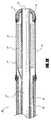
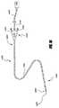
図2Aは具体的な超音波カテーテル組立体60の選択された構成部材の軸線方向断面図であるが、このカテーテル組立体は抹消血管閉塞箇所の治療に特に好適であるとともに、空洞形成推進面61が設けられている。カテーテル組立体60は治療用調剤搬送管腔62、冷却液搬送管腔63、温度センサー64、および、超音波放射部材配列66を収容することができる超音波芯材65を備えている。これら構成要素の或るものは任意であり、代替の実施形態からは省かれる。空洞形成推進面61のカテーテル組立体60の上の位置は、超音波放射部材配列66の位置に基づいて選択される。具体的な実施形態では、空洞形成推進面61はカテーテル本体部67の領域上で、超音波放射部材配列66が設置されるような構成になっている領域に隣接しているところにのみ配置されている。空洞形成推進面61の空間的広がりをこのように制限することで、空洞形成推進面61はカテーテル組立体60の血管内操作性に悪影響があるとすれば、そのような悪影響が緩和されているという点で有利である。具体的な一実施形態では、カテーテル本体部67の外径は約0.043インチであるが、他の実施形態ではこれ以外の寸法が採用される。 FIG. 2A is an axial cross-sectional view of selected components of a specific
同様に、図2Bは具体的な超音波カテーテル組立体70の選択された構成部材の長軸線方向断面図を例示しているが、かかる組立体は脳内血管閉塞箇所の治療に特に好適であるとともに、空洞形成推進面71が設けられている。例示の実施形態では、空洞形成推進面71は超音波放射部材外皮75の上に形成されているが、外皮75が省かれている変更例では、空洞形成推進面71はカテーテル外側本体部76の上に、直接、形成されている。カテーテル組立体70は、ガイドワイヤ、治療用調剤、および/または、冷却液などのような物質を通す構成の作業管腔72の外郭を画定している内部芯材73を備えている。カテーテル組立体は、遠位先端部材74と中空の円筒状超音波放射部材77とを更に備えており、後者は内部芯材73に搭載されている。このような構成部材の或るものは任意であり、代替の実施形態では省かれている。具体的な一実施形態では、空洞形成推進面71は超音波放射部材77に隣接して設置されているだけである。空洞形成推進面71の空間的広がりをこのように制限することで、空洞形成推進面71はカテーテル組立体70の血管内操作性に悪影響があるとすれば、そのような悪影響が緩和されているという点で有利である。具体的な一実施形態では、カテーテル外側本体部76の直径は約5 Frenchよりも短いが、他の実施形態ではこれ以外の寸法が採用されている。 Similarly, FIG. 2B illustrates a longitudinal cross-sectional view of selected components of a specific
具体的な一実施形態では、図2Bに例示されている超音波放射部材77は管状の圧電セラミックトランスデューサーであり、これは、長さモード、厚さモード、および、周長モードで超音波エネルギーを放射することができる。超音波放射部材77は、約78Wcm-2から約98Wcm-2の間であるのが好ましいパルス平均空間ピーク出力を生成することができるが、このピーク出力は約88Wcm-2であるのがより好ましい。この結果として生じるピーク音圧は、約0.7 MPaから約2.2 MPaであるのが好ましいが、約1.2 MPaから約1.6 MPaであるのがより好ましい。In one specific embodiment, the ultrasonic radiating member 77 illustrated in FIG. 2B is a tubular piezoceramic transducer, which is ultrasonic energy in length mode, thickness mode, and circumferential length mode. Can be emitted. The ultrasonic radiating member 77 can produce a pulse average spatial peak power that is preferably between about 78 Wcm−2 and about 98 Wcm−2 , but this peak power is more preferably about 88 Wcm−2. . The resulting peak sound pressure is preferably from about 0.7 MPa to about 2.2 MPa, more preferably from about 1.2 MPa to about 1.6 MPa.
修正された実施形態では、超音波放射部材77は厚みモードで共鳴周波数が約1 MHzよりも大きいか、または、それに等しい。或る実施形態では、超音波カテーテルに設けられている超音波放射部材は、任意であるが、ニッケルめっき電極のような、そこに電気ワイヤを半田付けすることができる電極を備えている。 In a modified embodiment, the ultrasound radiating member 77 is in thickness mode and has a resonance frequency greater than or equal to about 1 MHz. In some embodiments, the ultrasound radiating member provided on the ultrasound catheter optionally comprises an electrode, such as a nickel plated electrode, onto which an electrical wire can be soldered.
図17は、本件に開示されている実施形態のうちの或るものと併用することができるとともに、図16に例示されているフィードバック制御系1100の一実施形態を例示している。フィードバック制御系1100により、温度センサー1201の温度を監視することができるようにするとともに、それに応じてエネルギー源1700の出力を調節することができるようになる。任意で、医者は閉ループシステムまたは開ループシステムの作動を無効にすることができる。フィードバック制御系1100はエネルギー源1700、電力回路1072、および、超音波放射部材1040に接続されている出力計算装置1074を備えている。温度測定装置1760が温度センサー1201に接続されているが、このセンサーは管状本体部1200に配置されている。処理装置1078が出力計算装置1074と、電力回路1072と、ユーザーインターフェイスおよび表示装置1080とに接続されている。 FIG. 17 illustrates one embodiment of the
作動時には、温度センサー1201の温度は温度測定装置1760によって判定される。処理装置1078は温度測定装置1760から判定温度を1つごとに受信する。次に、判定された温度はユーザーインターフェイスおよび表示装置1080でユーザーに対して表示される。ユーザーインターフェイスおよび表示装置1080は、ユーザーによって定められた所望の温度のようなユーザー入力を受信することができる。修正された実施形態では、所望の温度は処理装置1078内で予備設定され、ユーザーによる変更は行えない。処理装置1078は温度制御信号を生成する論理を含んでいる。温度制御信号は測定温度と所望の温度との間の差に比例している。 In operation, the temperature of the
温度制御信号は電力回路1072によって受信される。電力回路1072は、任意で、エネルギー源1700から超音波放射部材1040に供給された電気エネルギーの出力レベル、位相、および/または、電流を調節するような構成になっている。例えば、温度制御信号が特定レベルより高い場合には、超音波放射部材1040に供給される出力は温度制御信号に応答して低減される。同様に、温度制御信号が特定レベルよりも低い場合には、超音波放射部材1040に供給される出力は温度制御信号に応答して増大される。出力調節を行う度ごとに、処理装置1078が任意で温度センサー1201を監視し、電力回路1072によって受信されているまた別な温度制御信号を生成する。 The temperature control signal is received by the
任意で、処理装置1078は安全制御論理を更に含んでいる。例えば、治療部位の組織が摂氏6度を越えて上昇するのを阻止するのが一般に望ましい。安全制御論理は、温度センサー1201の温度が安全閾を超過したか否かを検出する。次に、処理装置1078は温度制御信号を生成するが、この信号により、電力回路1072はエネルギー源1700から超音波放射部材1040へのエネルギー搬送を中止する。また別な実施形態では、電力回路1072からの出力は選択された長さの時間に亘って超音波放射部材1040に対して選択されたエネルギーを維持する。 Optionally, the
或る実施形態では、処理装置1078は出力計算装置1074からの出力信号も受信する。出力信号を利用して、超音波放射部材1040によって受信されている出力を判定する。判定された出力はユーザーに対してユーザーインターフェイスおよび表示装置1080上に表示される。 In some embodiments, the
処理装置1078は、ソフトウエアを組み込んだコンピュータのようなディジタル制御装置またはアナログ制御装置を備えていてもよい。処理装置1078がコンピュータである実施形態では、コンピュータは、任意であるが、中央処理装置(CPU)がシステムバスを介して接続されている。ユーザーインターフェイスおよび表示装置1080は、任意で、マウス、キーボード、ディスクドライブ、表示モニター、および、不揮発性メモリシステムを備えている。また任意で、プログラムメモリとデータメモリがバスに接続されている。 The
上述の一連の出力調節の代わりに、超音波放射部材1040に搬送される出力のプロファイルが処理装置1078に組み込まれて、予備設定された量の搬送されるべき超音波エネルギーが事前にプロファイル化されるようになっている。このような実施形態では、超音波放射部材1040に搬送された出力は予備設定されたプロファイルに従って調節される。例えば、任意で処理装置1078に組み込まれた複数の超音波波形が本件に開示されている。処理装置はまた、任意で、個別であれ、または、グループごとであれ、いずれかの態様で複数の超音波放射部材を個別に制御することができる。 Instead of the series of power adjustments described above, a profile of the power delivered to the
本件で使用されているような「超音波造影剤」という語は広義に使用されており、通常使用の意味を含んでいるとともに、安定化されてガスが充満した、直径範囲が約10 nmから約50μmの超微小泡と微小泡を含有している化合物も意味している。超音波造影剤は診断目的で超音波画像化システムと広く併用されているが、これら造影剤は外来の空洞核源としても作用する。音波により活性化された超音波造影剤は血栓分解を向上させるとともに、治療用調剤搬送を向上させることが分かっている。超音波造影剤を血管内治療部位に全身搬送することは比較的非効率であるうえに、互い服用レベルによって引き起こされる全身系合併症の危険を伴う。よって、流体搬送を行うことができる超音波カテーテルを利用して治療部位まで、直接、超音波造影剤を局所搬送することは、概ね好ましい。 The term “ultrasound contrast agent” as used in the present case is used broadly and includes the meaning of normal use and is stabilized and filled with gas, with a diameter range from about 10 nm. It also means a compound containing ultrafine bubbles and fine bubbles of about 50 μm. Ultrasound contrast agents are widely used in conjunction with ultrasound imaging systems for diagnostic purposes, but these contrast agents also act as extraneous cavity nuclear sources. Ultrasound contrast agents activated by acoustic waves have been shown to improve thrombus degradation and improve therapeutic dispensing. Systemic delivery of ultrasound contrast agents to the endovascular treatment site is relatively inefficient and carries the risk of systemic complications caused by each other's dose levels. Therefore, it is generally preferable to locally deliver the ultrasound contrast agent directly to the treatment site using an ultrasound catheter capable of fluid delivery.
図3は、選択された具体的な実施形態ごとに超音波エネルギー被爆時間の関数として生体内プラズマ血餅モデルの相対的渙散を示したグラフである。図3に例示されているデータを得るために使用される超音波エネルギーの周波数は約1 MHzであり、ピーク圧は約1.6 MPaであり、デューティー際クロは約7.5%である。第一の具体的実施形態では、プラズマ血餅モデルは治療エネルギーと治療用調剤に曝された。第2の具体的実施形態では、プラズマ血餅モデルは超音波エネルギーと超音波造影剤に曝された。第2の具体的実施形態では、プラズマ血餅モデルは超音波エネルギー、治療用調剤、および、超音波造影剤に曝された。このような3つの具体的実施形態では、治療用調剤はアクティヴェース−登録商標ACTIVASE−組織プラスミノゲン活性化因子(カリフォルニア州サウスサンフランシスコのジェネンテク・インコーポレーティッドス(Genentech, Inc)から入手可能)であり、超音波造影剤はオプティソン−登録商標OPTISON(ミズーリ州セントルイスのマリンクロート・ファーマシューティカルズ(Mallinckrodt Pharmaceuticals)から入手可能)であった。このような3つの具体的実施形態のプラズマ血餅モデルの分解は、治療調剤のみを使って治療されたプラズマ血餅モデルの分解と比較された。 FIG. 3 is a graph showing the relative dispersion of the in vivo plasma clot model as a function of ultrasonic energy exposure time for each selected specific embodiment. The frequency of ultrasonic energy used to obtain the data illustrated in FIG. 3 is about 1 MHz, the peak pressure is about 1.6 MPa, and the duty cycle is about 7.5%. In a first specific embodiment, the plasma clot model was exposed to therapeutic energy and therapeutic formulation. In a second specific embodiment, the plasma clot model was exposed to ultrasound energy and ultrasound contrast agent. In a second specific embodiment, the plasma clot model was exposed to ultrasound energy, therapeutic preparation, and ultrasound contrast agent. In three such specific embodiments, the therapeutic preparation is ACTIVES® ACTIVASE-tissue plasminogen activator (available from Genentech, Inc., South San Francisco, Calif.). The ultrasound contrast agent was Optison® OPTISON (available from Mallinckrodt Pharmaceuticals, St. Louis, MO). The degradation of the plasma clot model of these three specific embodiments was compared with the degradation of the plasma clot model treated with only the therapeutic preparation.
図3では、斜線を施した領域80は超音波エネルギーと治療用調剤を利用して治療されたプラズマ血餅モデルの相対渙散を示しており、斜線を施した領域82は超音波エネルギーと超音波造影剤を使って治療されたプラズマ血餅モデルの相対渙散を示しており、空白領域84は超音波エネルギー、治療用調剤、および、超音波造影剤を使って治療されたプラズマ血餅モデルの相対渙散を示している。図3に提示されているデータは、超音波造影剤と治療用調剤の組合せが単なる相加的血餅渙散効果ではなく相乗的血餅渙散効果を生じているのを示している。より詳細に述べると、超音波エネルギーへの被爆時間が少なくとも約5秒になると、治療用調剤のみを使った治療または超音波造影剤のみを使った治療の個別の相対血餅渙散の総和と比べて、治療用調剤と超音波造影剤を組合わせた治療の相対地餅渙散の方が著しく高率である。 In FIG. 3, the hatched
粗面の肌理を設けた、または、そのような肌理を設けていない疎水性材料が液中に浸漬されると、小さいガスポケットが粗面の小さいひびや裂け目に捕獲される。このような浸漬は「不完全浸潤」と呼ばれることが多い。ガスポケットは浸漬液中に溶解することに抵抗して安定化される。このような面の具体例として、粗面処理されたポリテトラフルオロエチレン面や粗面処理されたポリイミド面が挙げられる。超音波造影剤中の微小泡と同様に、このようなガスポケットは空洞核源として作用することもできる。より詳細に説明すると、或る実施形態では、超音波エネルギーを使って、粗面処理された疎水性表面の上の安定化したガスポケットから泡を抽出し、抽出された自由な微小泡を空洞形成核源として利用する。このような表面は、通例、空洞形成推進面と呼ぶ。本件に記載されているように、また、図2Aおよび図2Bに例示されているように、空洞形成推進面は血管内カテーテルの或る実施形態の外面上に組み込まれている。 When a hydrophobic material with or without a rough texture is immersed in the liquid, small gas pockets are trapped in small cracks and tears on the rough surface. Such immersion is often referred to as “incomplete infiltration”. The gas pocket is stabilized against resistance to dissolution in the immersion liquid. Specific examples of such a surface include a roughened polytetrafluoroethylene surface and a roughened polyimide surface. Similar to microbubbles in ultrasound contrast agents, such gas pockets can also act as a cavity nucleus source. More particularly, in one embodiment, ultrasonic energy is used to extract bubbles from a stabilized gas pocket on a roughened hydrophobic surface and to cavitate the extracted free microbubbles. Use as a source of formation nuclei. Such a surface is commonly referred to as a cavitation promoting surface. As described herein, and as illustrated in FIGS. 2A and 2B, the cavitation promoting surface is incorporated on the outer surface of an embodiment of the intravascular catheter.
空洞形成推進面上の空洞核形成の現象は、幾つかの観点では、泡形成の閾レベルが粗面上の安定化したガスポケットの存在とそのようなガスポケットの界面張力で決まるという点で、沸騰現象に類似している。図1Aは安定したガスポケット10が液体30によって包囲されている裂け目20の内側に置かれているのを例示している。図1Bに例示されているように、安定したガスポケット10が音波40の希薄部に曝されると、周囲の液体30の低下圧に応じて安定したガスポケットの容積が増大する。図1Cに例示されているように、安定したガスポケット10の一部が裂け目20から潰し出されて排出されることで、自由な微小泡50を形成する。この具体例では、裂け目20は、自由な微小泡を排出するのに十分な振動機械圧を有している超音波エネルギーに曝されると「活性化」する空洞核形成部位として作用する。 The phenomenon of cavity nucleation on the cavitation propulsion surface is, in some respects, that the threshold level of bubble formation is determined by the presence of stabilized gas pockets on the rough surface and the interfacial tension of such gas pockets. Similar to the boiling phenomenon. FIG. 1A illustrates that a
従って、液体に石、破片、または、粒子を添加すると液体の沸騰温度が下がる態様と同じように、カテーテルに粗面を添加することで、カテーテル面の上に超音波空洞形成を達成するのに必要な音圧閾が下がる。これは超音波カテーテルを使って治療部位に空洞形成を誘発するのに関連して特に有益であるが、というのも、空洞形成推進面が存在していない場合に(すなわち、平滑なカテーテル面から)自由な泡を生成するための閾パルス平均空間ピーク出力強度は、12 msから250 msの間の被爆期間で1.8 MHzの合焦超音波場を利用した場合には、19000 Wcm-2程度の高さになるからである。空洞形成推進面が存在していない場合に空洞形成を誘発するための閾音圧は6.3 MPaよりも高いが、空洞形成推進面が存在している場合には約2.7 MPa程度の低さである。従って、空洞形成推進面を利用することで、空洞形成を誘発するために治療部位に搬送されなければならない超音波エネルギーの量を低減することにより、(a)超音波エネルギーを搬送するために使用されている超音波放射部材の作動寿命が延びる、更に、(b)治療部位に損傷を引き起こす可能性を減少することにより治療の安全性を高める、という利点がある。Thus, adding stones, debris, or particles to the liquid lowers the boiling temperature of the liquid, adding a rough surface to the catheter to achieve ultrasonic cavity formation on the catheter surface. The required sound pressure threshold is lowered. This is particularly beneficial in connection with inducing cavitation at the treatment site using an ultrasonic catheter, since there is no cavitation propulsion surface (ie, from a smooth catheter surface). ) The threshold pulse average spatial peak output intensity for generating free bubbles is about 19000 Wcm-2 when using a 1.8 MHz focused ultrasound field with an exposure period between 12 ms and 250 ms. Because it becomes height. The threshold sound pressure for inducing cavitation in the absence of a cavitation propulsion surface is higher than 6.3 MPa, but in the presence of a cavitation propulsion surface, it is as low as about 2.7 MPa. . Thus, by utilizing the cavitation propulsion surface, (a) used to deliver ultrasonic energy by reducing the amount of ultrasonic energy that must be delivered to the treatment site to induce cavitation. This has the advantage of extending the operational life of the ultrasound radiating member being used, and (b) increasing the safety of the treatment by reducing the possibility of causing damage to the treatment site.
液体は疎水性の素材を均一には浸潤しない傾向があるため、このような素材は一般に高密度の空洞核形成部位を設けるのには好適である。付加的なひびや裂け目を生じるように表面を粗面処理することなどで上述のような素材の表面を修正することで、空洞核形成部位をより多く生じさえするようになる。比較的小さい裂け目(約10μmよりも小さいか、それに等しい寸法)を有している表面については、表面張力は微小泡核形成の支配的で影響力のある要因である。 Since liquids do not tend to infiltrate hydrophobic materials uniformly, such materials are generally suitable for providing high density cavity nucleation sites. By modifying the surface of the material as described above, such as by roughening the surface to produce additional cracks or crevices, even more cavity nucleation sites are created. For surfaces with relatively small tears (dimensions less than or equal to about 10 μm), surface tension is the dominant and influential factor in microbubble nucleation.
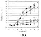
或る応用例では、空洞形成を推進するにあたっての特定のカテーテル方面の効果を判定する手段として、代表的な溶液(ろ過処理後のガス飽和状態の摂氏37度の水または摂氏337度のプラズマ血餅)の中に表面を浸漬し、表面を超音波エネルギーに曝し、生成された微小泡の活性量を観察するという方法が採られる。例えば、一応用例では、カテーテル面は超音波エネルギーに曝され、平均広帯域ノイズが超音波エネルギーにより生成されたピーク音圧の関数として測定される。図4は、平滑なポリイミド面(線90)、砂研磨処理されたポリイミド面(線92)、ポリテトラフルオロエチレン皮膜が設けられた面(線94)、および、パリレン皮膜が設けられた面(線96)についての上述の測定結果を例示している。ポリテトラフルオロエチレン皮膜とパリレン皮膜は両方ともが疎水性であるが、パリレンの粗面度はポリテトラフルオロエチレンよりも遥かに精細である。 In some applications, a representative solution (37 degrees Celsius water or 337 degrees Celsius of plasma saturation after filtration) is used as a means of determining the effect of a particular catheter direction in promoting cavity formation. The method of immersing the surface in (ii), exposing the surface to ultrasonic energy, and observing the active amount of the generated microbubbles is employed. For example, in one application, the catheter surface is exposed to ultrasonic energy and the average broadband noise is measured as a function of the peak sound pressure generated by the ultrasonic energy. FIG. 4 shows a smooth polyimide surface (line 90), a sand-polished polyimide surface (line 92), a surface provided with a polytetrafluoroethylene film (line 94), and a surface provided with a parylene film (line 94). The above measurement results for line 96) are illustrated. Both the polytetrafluoroethylene film and the parylene film are hydrophobic, but the roughness of parylene is much finer than that of polytetrafluoroethylene.
特定のカテーテル面に対する平均広帯域ノイズが特定の検出装置に対する広帯域ノイズ検出閾レベルよりも高い場合には、線98で表されているように、惰性空洞形成が存在しているのが明らかになる。具体的な一実施形態では、ノイズ検出閾は空洞形成推進面が設けられていないカテーテルについて観察された広帯域ノイズに基づいているが、その際の空洞形成推進面は短い圧力振幅を有している超音波エネルギーに曝されている、空洞形成閾が高い媒体中にある。図4は、ポリテトラフルオロエチレン皮膜と砂研磨処理されたポリイミド皮膜は、或る実施形態においては特に効率のよい空洞形成推進面として作用するが、それは、このような面の音圧閾が特に低いせいで安定した惰性空洞形成を生じるからであることを示している。 If the average broadband noise for a particular catheter surface is higher than the broadband noise detection threshold level for a particular detection device, it becomes clear that inertial cavity formation is present, as represented by
特定のカテーテル面に対する低調波ノイズの大きさが特定の検出装置に対する低調波ノイズ検出閾レベルよりも高い場合には、安定した空洞形成が存在していることが明らかになる。特定のカテーテル面に対する低調波ノイズの大きさを得る手段として、まず、測定された時間領域信号の高速フーリエ変換(FFT)を実施してから、超音波放射部材の基本周波数(すなわち、低調波周波数)の半分のレベルでFFTスペクトルの振幅を測定する方法が採られる。低調波周波数付近の局所的なノイズの底値は、任意であるが、この振幅から差し引かれて、惰性空洞形成によって引き起こされた広帯域ノイズレベルの上昇のせいで低調波信号の原因となる。具体的な一実施形態では、低調波ノイズ検出閾は、空洞形成推進面が設けられていないカテーテルについて観察される低調波ノイズに基づいているが、この場合の空洞形成推進面は、短い圧力振幅を示す超音波エネルギーに曝されている、空洞形成閾レベルが高い媒体の中にある。空洞形成活動の集成の程度は、治療の持続中に亘り検出されたノイズを積分することにより、定量化することができる。 If the magnitude of the subharmonic noise for a particular catheter surface is higher than the subharmonic noise detection threshold level for a particular detector, then it becomes clear that stable cavity formation exists. As a means of obtaining the magnitude of the subharmonic noise for a specific catheter surface, first the fast Fourier transform (FFT) of the measured time domain signal is performed, and then the fundamental frequency of the ultrasound emitting member (ie, the subharmonic frequency). ) Is used to measure the amplitude of the FFT spectrum at half the level. The local noise floor near the subharmonic frequency is arbitrary, but is subtracted from this amplitude, causing the subharmonic signal due to the increased broadband noise level caused by inertial cavity formation. In one specific embodiment, the subharmonic noise detection threshold is based on the subharmonic noise observed for a catheter that is not provided with a cavitation propulsion surface, where the cavitation propulsion surface has a short pressure amplitude. In a medium with a high cavitation threshold level that is exposed to ultrasonic energy indicative of The degree of cavitation activity aggregation can be quantified by integrating the detected noise over the duration of the treatment.
また別な実施形態では、治療部位において生じた空洞形成の量を測定する手段として、ワシントン州ボセルのソノサイト・インコーポレーティッド(SonoSite, Inc.)から入手することができるソノサイト−登録商標SONOSITE−180携帯超音波画像化システムのような超音波画像化システムを利用して泡の活動を観察する方法が採られる。このような実施形態では、泡の活動量は、泡の活性状態が観察されている期間に値1を割り当て、泡の活動が観察されていない期間に値0を割り当てることによって、定量化することができる。これら2元評点の平均は、所与の形状に対して泡が生成される可能性に対応している。図5Aおよび図5Bは、砂研磨処理されたポリイミド管をプラズマ血餅中に設置してから5.1 MPaのピーク音圧を示す超音波エネルギーに曝した場合に生成される微小泡の活動を例示している。超音波エネルギーのパルスプロファイルが図7に例示されているような多種類の圧力振幅を含んでいる実施形態では、空洞形成活動は、任意であるが、超音波エネルギーパルスの大きい圧力振幅段階と短い圧力振幅段階が持続している期間は別々に測定される。 In yet another embodiment, SONOSITE-180, a sonosite-registered trademark available from SonoSite, Inc. of Bothell, Washington, as a means of measuring the amount of cavitation that occurs at the treatment site. A method of observing bubble activity using an ultrasound imaging system such as a portable ultrasound imaging system is employed. In such an embodiment, the amount of foam activity is quantified by assigning a value of 1 to a period during which foam activity is observed and a value of 0 to a period during which no foam activity is observed. Can do. The average of these binary scores corresponds to the likelihood that bubbles will be generated for a given shape. 5A and 5B illustrate the activity of microbubbles generated when a sand-polished polyimide tube is placed in a plasma clot and then exposed to ultrasonic energy exhibiting a 5.1 MPa peak sound pressure. ing. In embodiments where the pulse profile of the ultrasonic energy includes multiple types of pressure amplitudes as illustrated in FIG. 7, the cavitation activity is optional but short with a large pressure amplitude step of the ultrasonic energy pulse. The period during which the pressure amplitude phase lasts is measured separately.
空洞形成推進面が設けられているカテーテルが血管閉塞箇所の内部に設置されると、超音波エネルギーの供与時に生成される空洞形成量は、血管閉塞箇所に治療用調剤を供給することによって向上させられる。例えば、図5Aは、治療用調剤がプラズマ血餅に添加されている場合の微小泡の活動を例示しているが、図5Bは1.0 mLの治療用調剤がプラズマ血餅に添加された場合に微小泡活動が顕著に増大するのを例示している。理論による制限が無ければ、この効果が生じる原因は、治療用調剤が空洞形成推進面の領域において塞栓箇所を「軟化し」、「開き」、または、部分的に渙散することで、周囲の液体環境中に泡をより容易に生成することができるようにしたことであると思われる。 When a catheter with a cavitation propulsion surface is installed inside a vascular occlusion site, the amount of cavitation generated when ultrasound energy is supplied is improved by supplying a therapeutic preparation to the vascular occlusion site. It is done. For example, FIG. 5A illustrates microbubble activity when a therapeutic preparation is added to the plasma clot, while FIG. 5B illustrates when 1.0 mL of the therapeutic preparation is added to the plasma clot. Illustrates a significant increase in microbubble activity. Without theoretical limitation, this effect occurs because the therapeutic formulation “softens”, “opens”, or partially dissipates the embolization site in the area of the cavitation propulsion surface, and the surrounding liquid It seems that it was possible to generate bubbles in the environment more easily.
具体的な一実施形態では、超音波カテーテルを使って、プラズマ血餅を超音波エネルギーと治療用調剤に約30分間に亘って曝す。パルス持続時間は約1 Hzのパルス繰返し周波数で約50回分の炸裂周期であるが、これは、デューティーサイクルの約0.003%に対応する。これは超音波カテーテルの外側面において約2.4 MPaの音波空間平均圧と約2.8 MPaの空間ピーク圧を生じる。超音波カテーテルに空洞形成推進面が設けられていない実施形態と比べて、超音波カテーテルに空洞形成推進面が設けられている実施形態では、プラズマ血餅の渙散率は約15.6%±5.83%だけ向上される。従って、超音波をベースにした血栓溶解処置は、治療部位における空洞形成量を増大させるために空洞形成推進面を採用することによって改善される。或る実施形態では、空洞形成推進面を使用することで、治療部位に搬送される超音波エネルギーの量が低下するにも関わらず、血栓溶解率の向上を達成することができるようになる。 In one specific embodiment, an ultrasonic catheter is used to expose the plasma clot to ultrasonic energy and therapeutic preparation for about 30 minutes. The pulse duration is about 50 burst cycles at a pulse repetition frequency of about 1 Hz, which corresponds to about 0.003% of the duty cycle. This produces a sonic spatial average pressure of about 2.4 MPa and a spatial peak pressure of about 2.8 MPa on the outer surface of the ultrasound catheter. Compared to the embodiment in which the ultrasonic catheter is not provided with a cavitation promoting surface, in the embodiment in which the ultrasonic catheter is provided with a cavitation promoting surface, the diffusion rate of plasma clot is only about 15.6% ± 5.83% Be improved. Thus, ultrasound-based thrombolysis procedures are improved by employing a cavitation propulsion surface to increase the amount of cavitation at the treatment site. In some embodiments, the use of a cavitation propulsion surface allows an increase in thrombolysis rate to be achieved despite a reduction in the amount of ultrasonic energy delivered to the treatment site.
ここに説明されているように、また、図4に例示されているように、或る粗面処理された面および/または疎水性の面は核形成部位に自由微小泡をもたらすが、これにより、各面が超音波エネルギーに曝された時に空洞形成を向上させることができる。或る実施形態では、疎水性の面を利用してカテーテルの潤滑性を増大させることで、血管内治療部位にカテーテルを容易に搬送することができるようにしている。ポリイミドは比較的疎水性に富む材料であり、これは生体適合性であり、血管内カテーテルの製造で広く使用される。或る実施形態では、ポリイミドの疎水性は、シリコンをベースにした化合物およびポリテトラフルオロエチレンをベースにした化合物のような高疎水性皮膜を付与することによって高められる。これ以外の実施形態では、ポリイミドの疎水性は、事前に分散させられた疎水性粒子をポリイミドの中に混成または混合することにより、高められる。 As described herein, and as illustrated in FIG. 4, certain roughened and / or hydrophobic surfaces result in free microbubbles at the nucleation site, which Cavity formation can be improved when each surface is exposed to ultrasonic energy. In some embodiments, the hydrophobic surface is utilized to increase the lubricity of the catheter so that the catheter can be easily delivered to the endovascular treatment site. Polyimide is a relatively hydrophobic material that is biocompatible and widely used in the manufacture of intravascular catheters. In some embodiments, the hydrophobicity of the polyimide is increased by applying highly hydrophobic coatings such as silicon-based compounds and polytetrafluoroethylene-based compounds. In other embodiments, the hydrophobicity of the polyimide is increased by hybridizing or mixing predispersed hydrophobic particles into the polyimide.
例えば、ポリテトラフルオロエチレンは、ポリイミドに混合することができるとともに次のような他の重要な利点を有している粒子である。すなわち、ポリイミドは他の重合体と比べて運動摩擦係数(μk)が比較的小さく、運動摩擦係数(μk)と比べて静止摩擦係数(μs)が低い、という利点を有している。混合されたポリテトラフルオロエチレン粒子の寸法と濃度は、結果として生じる空洞形成推進面の肌理と疎水性に影響を与える。図6Aは平坦なポリイミド面の顕微鏡画像(200x)であるが、図6Bはポリイミド面にポリテトラフルオロエチレン粒子が散乱されているのを表している顕微鏡画像(200x)である。For example, polytetrafluoroethylene is a particle that can be mixed with polyimide and has other important advantages as follows. That is, polyimide has the advantage that the coefficient of kinetic friction (μk ) is relatively small compared to other polymers, and the coefficient of static friction (μs ) is lower than that of kinetic friction (μk ). . The size and concentration of the mixed polytetrafluoroethylene particles affects the texture and hydrophobicity of the resulting cavitation promoting surface. 6A is a microscopic image (200x) of a flat polyimide surface, while FIG. 6B is a microscopic image (200x) showing that polytetrafluoroethylene particles are scattered on the polyimide surface.
また別な実施形態では、空洞形成推進面はカテーテル面を粗面処理することにより得られる。そのような実施形態の一例では、粗面処理を達成するにあたり、得られる粗面度のレベルに基づいて選択される格子寸法の微小研摩器具と研摩材を利用して砂研摩処理を行う。例えば、好適な研摩材の一例は、平均直径が約25μmの酸化アルミニウム粒子の粉末である。酸化アルミニウムとそれ以外の同様の研摩材は乾燥した媒体であり、これは、粗面処理が実施された後でカテーテル面の洗浄を容易にするという点で有利である。また別な実施形態では、水をベースにした化合物またはグリースをベースにした化合物を使って、カテーテル面により精細な研摩部を設けるよう図っているが、そうでなければ、乾燥した研摩媒体を使っても実施可能である。グリースをベースにした化合物と比べて、水をベースにした化合物の使用は、処理後のカテーテル面の洗浄を容易にするという点で有利である。水をベースにした化合物とグリースをベースにした化合物は手動の応用技術と機械をベースにした応用技術の両方と適合性がある。例えば、好適な応用技術の一例は、研摩化合物中にカテーテルを浸漬してから超音波エネルギーを使って化合物を攪拌することで、化合物中の微細粒子がカテーテル本体部を擦り、カテーテル本体部に擦傷と裂け目を生じることを含んでいる。一実施形態では、カテーテル面は、血液と接触した際に血栓形成状態になって血餅形成を促進するほど粗面ではない。 In another embodiment, the cavitation promoting surface is obtained by roughening the catheter surface. In one example of such an embodiment, in order to achieve the roughening process, a sand polishing process is performed using a micro-abrasive tool and abrasive of a lattice size selected based on the level of roughness obtained. For example, one example of a suitable abrasive is a powder of aluminum oxide particles having an average diameter of about 25 μm. Aluminum oxide and other similar abrasives are dry media, which is advantageous in that it facilitates cleaning of the catheter surface after the roughening has been performed. In another embodiment, a water-based compound or grease-based compound is used to provide a finer polish on the catheter surface; otherwise, a dry polishing medium is used. However, it can be implemented. Compared to grease-based compounds, the use of water-based compounds is advantageous in that it facilitates cleaning of the catheter surface after treatment. Water-based compounds and grease-based compounds are compatible with both manual and machine-based applications. For example, one suitable application technique is to immerse the catheter in an abrasive compound and then stir the compound using ultrasonic energy so that the fine particles in the compound rub the catheter body and scratch the catheter body. And including creating a tear. In one embodiment, the catheter surface is not rough enough to enter the thrombus state when contacted with blood and promote clot formation.
具体的な一実施形態では、血管塞栓箇所の渙散は、空洞形成推進面が設けられているカテーテルから超音波エネルギーを搬送することによって達成される。例えば、一実施形態では、超音波エネルギーのデューティーサイクルは約0.001%から約0.005%の間であるのが好ましく、約0.003%であるのがより好ましい。また別な実施形態では、超音波エネルギーのデューティーサイクルは約3.5%から約13.5%の間であるのが好ましく、約8.5%であるのがより好ましい。超音波エネルギーの周波数は約1.2 MHzから約2.2 MHzの間であるのが好ましく、約1.7 MHzであるのがより好ましい。超音波エネルギーはパルス繰返し周波数が約0.5 Hzから約1.5 Hzの間であるのが好ましく、約1 Hzであるのがより好ましい。超音波エネルギーのパルス持続時間は約5000回の炸裂周期から約7000回の炸裂周期の間を占めるのが好ましく、約5950回の炸裂周期を含んでいるのがより好ましい。超音波エネルギーのピーク音圧は約1.8 MPaから約3.8 MPaの間であるのが好ましく、約2.8 MPaであるのがより好ましい。超音波エネルギーの空間平均音圧は約1.4 MPaから約3.4 MPaであるのが好ましく、約2.4 MPaであるのがより好ましい。しかしながら、修正後の実施形態では、超音波エネルギーの周波数、デューティーサイクル、および/または、パルス持続時間を適切に調節することにより、実質的なトランスデューサー損傷を生ずることなく、より高いピーク音圧が生成される。 In one specific embodiment, vascular embolization site dispersion is achieved by delivering ultrasonic energy from a catheter provided with a cavitation promoting surface. For example, in one embodiment, the duty cycle of the ultrasonic energy is preferably between about 0.001% and about 0.005%, more preferably about 0.003%. In another embodiment, the duty cycle of the ultrasonic energy is preferably between about 3.5% and about 13.5%, more preferably about 8.5%. The frequency of the ultrasonic energy is preferably between about 1.2 MHz and about 2.2 MHz, more preferably about 1.7 MHz. The ultrasonic energy preferably has a pulse repetition frequency between about 0.5 Hz and about 1.5 Hz, more preferably about 1 Hz. The pulse duration of the ultrasonic energy preferably occupies between about 5000 burst cycles and about 7000 burst cycles, and more preferably includes about 5950 burst cycles. The peak sound pressure of the ultrasonic energy is preferably between about 1.8 MPa and about 3.8 MPa, more preferably about 2.8 MPa. The spatial average sound pressure of the ultrasonic energy is preferably about 1.4 MPa to about 3.4 MPa, more preferably about 2.4 MPa. However, in a modified embodiment, a higher peak sound pressure can be achieved without substantial transducer damage by appropriately adjusting the frequency, duty cycle, and / or pulse duration of the ultrasonic energy. Generated.
ここに説明されているように、患者の血管に過剰な超音波エネルギーが搬送されれば、治療部位を損傷する恐れもある。例えば、そのような損傷を引き起こす原因となりそうなのは、超音波エネルギーによって生成された過剰な熱エネルギーまたは過剰な剪断応力である。これに加えて、大きい圧力振幅で過熱したまま作動させると、超音波放射部材の作動寿命を実質的に縮めることになりかねない。従って、具体的な一実施形態では、超音波カテーテルは、治療部位および/または超音波放射部材に損傷を与える可能性を低減する態様で作動される。これを達成する1つの方法は、超音波放射部材が超音波エネルギーを搬送している時間を短くすることであり、これにより、治療部位に搬送される平均出力が実質的に低下する結果となる。これを達成するまた別な方法は、治療部位に空洞形成推進面を設置することである。 As described herein, if excessive ultrasonic energy is delivered to a patient's blood vessel, the treatment site may be damaged. For example, what is likely to cause such damage is excessive thermal energy or excessive shear stress generated by ultrasonic energy. In addition to this, if it is operated while being heated with a large pressure amplitude, the operating life of the ultrasonic radiation member may be substantially shortened. Accordingly, in one specific embodiment, the ultrasound catheter is operated in a manner that reduces the likelihood of damaging the treatment site and / or the ultrasound radiating member. One way to achieve this is to reduce the time that the ultrasound radiating member is delivering ultrasonic energy, which results in a substantial reduction in the average power delivered to the treatment site. . Another way to accomplish this is to place a cavitation promoting surface at the treatment site.
例えば、或る実施形態では、超音波放射部材は、切れ目無く継続する電気駆動出力の代わりに変調された電気駆動出力を利用するといった方法により、パルス修正されたモードで作動される。このような実施形態では、デューティーサイクルは、治療部位および/または超音波放射部材に熱損傷を生じることを回避するように選択される。超音波エネルギーの有益な効果は、超音波エネルギーの電源がオフ状態になった直後に途切れる。従って、或る実施形態では、超音波エネルギーの振幅および/または超音波エネルギー搬送の持続時間を増大させて臨床効果を高める一方で、超音波エネルギーのデューティーサイクルを低下させて、熱損傷の誘発を回避している。 For example, in certain embodiments, the ultrasound radiating member is operated in a pulse modified mode, such as by utilizing a modulated electrical drive output instead of a continuous electrical drive output. In such embodiments, the duty cycle is selected to avoid causing thermal damage to the treatment site and / or the ultrasound radiating member. The beneficial effect of ultrasonic energy is interrupted immediately after the ultrasonic energy is turned off. Thus, in certain embodiments, the amplitude of ultrasound energy and / or the duration of ultrasound energy delivery is increased to increase clinical effectiveness while reducing the duty cycle of ultrasound energy to induce thermal damage. It is avoiding.
或る構成では、治療部位に搬送される超音波出力が実質的に減少しているにも関わらず、超音波エネルギーの有益な効果は維持される。例えば、或る応用例では、治療部位において超音波により誘発された空洞形成が存在していることで、有益な効果を生む。典型例として、空洞形成を誘発するには、空洞形成閾出力Ctよりも高い出力を示す超音波エネルギーが治療部位に搬送される必要がある。しかしながら、治療部位で空洞形成を維持するには、より量を低下させた出力Cmを治療部位に搬送する必要があり、この場合、Cm<Ctが成立する。よって、このような実施形態では、空洞形成を誘発するために出力Ctの初期パルスが治療部位に搬送されるが、この後、空洞形成を維持するために、より低い出力量Cmが治療部位に搬送される。In some configurations, the beneficial effect of ultrasound energy is maintained despite a substantial decrease in the ultrasound power delivered to the treatment site. For example, in some applications, the presence of ultrasound-induced cavitation at the treatment site produces a beneficial effect. As a typical example, to induce cavitation, ultrasound energy that exhibits an output higher than the cavitation threshold output Ct needs to be delivered to the treatment site. However, in order to maintain the cavity formation at the treatment site, it is necessary to transport the output Cm with a reduced amount to the treatment site, and in this case, Cm <Ct is satisfied. Thus, in such an embodiment, an initial pulse of output Ct is delivered to the treatment site to induce cavitation, after which a lower output amount Cm is treated to maintain cavitation. It is transported to the site.
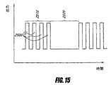
図8は具体的な超音波波形を例示している。或る応用例では、このような波形は、患者の血管内の治療部位に搬送され、任意で、治療用調剤の搬送を併用することで、治療効果をもたらす。図示のように、波形は一連の超音波エネルギーパルス2000を含んでおり、ピーク出力Pおよび持続時間Tを示している。これらのパルス2000は「電源オフ」期間2100によって分離されている。周期期間Tはパルスの立上げから次のパルスの立上げまでの間の時間として定義され、従って、パルス繰返し周波数(PRF)はT-1で表される。デューティーサイクルはパルスの立上げから次のパルス立上げまでの間の時間に対する1パルス時間の割合TT-1と定義され、超音波エネルギーが治療部位に搬送されている時間の分数を表している。1周期期間のうちに搬送される平均出力はPTT-1で表される。FIG. 8 illustrates a specific ultrasonic waveform. In certain applications, such a waveform is delivered to a treatment site within a patient's blood vessel, optionally with a therapeutic dispensing delivery, to provide a therapeutic effect. As shown, the waveform includes a series of
超音波エネルギーを使って血管内治療部位に搬送される治療用調剤の効果を向上させるように図っている具体的な一実施形態では、ピーク出力Pは約5ワットから約25ワットの間である。デューティーサイクルは約0.04よりも大きいのが好ましく、約0.06よりも大きいのがより好ましく、約0.085より大きいのが最も好ましい。平均出力は約0.45ワットよりも大きいか、または、この値に等しく、パルス繰返し周波数は約30 Hzである。このような波形によって生じる圧力は約1 MPaよりも高いのが好ましく、約2 MPaよりも高いのが更に好ましく、約2.5 MPaよりも高いのが最も好ましい。 In one specific embodiment that seeks to improve the effectiveness of a therapeutic formulation delivered to an endovascular treatment site using ultrasound energy, the peak power P is between about 5 watts and about 25 watts. . The duty cycle is preferably greater than about 0.04, more preferably greater than about 0.06, and most preferably greater than about 0.085. The average power is greater than or equal to about 0.45 watts and the pulse repetition frequency is about 30 Hz. The pressure generated by such a waveform is preferably higher than about 1 MPa, more preferably higher than about 2 MPa, and most preferably higher than about 2.5 MPa.
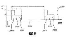
修正後の実施形態では、超音波エネルギーの有益な効果を著しく低下させることなしに、より少ない平均出力が治療部位に搬送される。より少ない平均出力を搬送することも、治療部位および/または超音波放射部材に熱損傷を引き起こす可能性を減らすという点で有利である。図9は、図8に例示されている具体的な波形と比較して、修正された超音波波形の平均出力が小さいことを例示している。図9に例示されている修正後の超音波波形も、患者の血管内の治療部位に搬送された際に治療効果をもたらすのに有用である。 In the modified embodiment, less average power is delivered to the treatment site without significantly reducing the beneficial effects of ultrasound energy. Conveying less average power is also advantageous in that it reduces the possibility of causing thermal damage to the treatment site and / or the ultrasound radiating member. FIG. 9 illustrates that the average output of the modified ultrasound waveform is small compared to the specific waveform illustrated in FIG. The modified ultrasound waveform illustrated in FIG. 9 is also useful for providing a therapeutic effect when delivered to a treatment site within a patient's blood vessel.
図9に例示されている修正後の超音波波形の一連の超音波エネルギーのパルス2000は、第1パルス部2010の期間中はピーク出力Pを示し、第2パルス部2020の期間中はより小さいピーク出力P'を示している。一応用例では、図8および図9に例示されている波形は、同じ周期期間Tと同じパルス持続時間Tを示している。また別な応用例では、図8に例示されている波形と比較して、図9に例示されている波形のデューティーサイクルは増大している。いずれの場合にせよ、図8に例示されている波形に比べて、図9に例示されている波形の平均出力は小さいが、それは、全パルス持続時間Tの間にはピーク出力Pが搬送されていないからである。しかしながら、図9に例示されている波形はそれでも、患者の血管内の治療部位に搬送された際に治療効果をもたらすのに有用である。例えば、或る実施形態では、ピーク出力Pは治療部位に空洞形成を誘発するのに十分な大きさであるが、それより小さい出力P'は治療部位の空洞形成を維持するのに十分な大きさである。A series of
図10は、図8に例示されている具体的な波形と比較して、また別な修正後の超音波波形の平均出力が小さいのを例示している。図10に例示されている修正後の超音波波形も、患者の血管内の治療部位に搬送された際により高い治療効果をもたらすのに有用である。このような波形は一連の超音波エネルギーパルス2200を含んでおり、立上がりパルス部2210と終端パルス部2230の期間には低下した出力P'を示し、その中間パルス部2220の期間にはピーク出力Pを示している。立上がりパルス部2210と終端パルス部2230の期間中の出力は同じである必要はない。図8に例示されている波形と図10に例示されている波形とでは周期期間Tとパルス持続時間Tが同じである。図8に例示されている波形に比べると、図10に例示されている修正後の超音波波形の平均出力は小さく、それは、全パルス持続時間Tの間にはピーク出力Pが搬送されていないからである。しかしながら、図10に例示されている波形はそれでも、患者の血管内の治療部位に搬送された際に治療効果をもたらすのに有用である。FIG. 10 illustrates that the average output of another corrected ultrasonic waveform is small compared to the specific waveform illustrated in FIG. The modified ultrasound waveform illustrated in FIG. 10 is also useful for providing a higher therapeutic effect when delivered to a treatment site within a patient's blood vessel. Such a waveform includes a series of
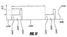
図11は、図8に例示されている具体的な波形と比較して、また別な修正後の超音波波形の平均出力が小さいのを例示している。図11に例示されている修正後の超音波波形も、患者の血管内の治療部位に搬送された際に治療効果をもたらすのに有用である。このような波形は一連の超音波エネルギーパルス2200を含んでおり、第1パルス部2240の期間中はより小さい出力P'を示し、第2パルス部2245の期間中はピーク出力Pを示している。図8に例示されている波形と図11に例示されている波形とでは周期期間Tとパルス持続時間Tが同じである。図8に例示されている波形に比べると、図11に例示されている修正後の超音波波形の平均出力は小さく、それは、全パルス持続時間Tの間にはピーク出力Pが搬送されていないからである。しかしながら、図11に例示されている波形はそれでも、患者の血管内の治療部位に搬送された際に治療効果をもたらすのに有用である。FIG. 11 illustrates that the average output of another corrected ultrasonic waveform is smaller than that of the specific waveform illustrated in FIG. The modified ultrasound waveform illustrated in FIG. 11 is also useful for providing a therapeutic effect when delivered to a treatment site within a patient's blood vessel. Such a waveform includes a series of
図12は、図8に例示されている具体的な波形と比較して、また別な修正後の超音波波形の平均出力が小さいのを例示している。図12に例示されている修正後の超音波波形も、患者の血管内の治療部位に搬送された際に治療効果をもたらすのに有用である。このような波形は一連の超音波エネルギーパルス2200を含んでおり、立上がりパルス部2246では低下した出力P'を示し、終端パルス部2248でピーク出力Pが生成されるまでは出力が徐々に上昇するのを示している。図8に例示されている波形と図12に例示されている波形とでは周期期間Tとパルス持続時間Tが同じである。図8に例示されている波形に比べると、図12に例示されている修正後の超音波波形の平均出力は小さく、それは、全パルス持続時間Tの間にはピーク出力Pが搬送されていないからである。しかしながら、図12に例示されている波形はそれでも、患者の血管内の治療部位に搬送された際に治療効果をもたらすのに有用である。FIG. 12 illustrates that the average output of another corrected ultrasonic waveform is smaller than that of the specific waveform illustrated in FIG. The modified ultrasound waveform illustrated in FIG. 12 is also useful for providing a therapeutic effect when delivered to a treatment site within a patient's blood vessel. Such a waveform includes a series of
図13は、図8に例示されている具体的な波形と比較して、また別な修正後の超音波波形の平均出力が小さいのを例示している。図13に例示されている修正後の超音波波形も、患者の血管内の治療部位に搬送された際に治療効果をもたらすのに有用である。このような波形の大きい振幅のパルス2300はピーク出力Pを示しており、1個以上の短い振幅のパルス2310は出力が小さい。図13は、短い振幅の1個以上のパルス2310に先行して大きい振幅のパルス2300が搬送されているのを例示しているが、他の実施形態ではまた別な搬送順序が採用される。例えば、一実施形態では、大きい振幅のパルス2300に先行して短い振幅の複数のパルスのうちの1個が搬送される。図8に例示されている波形と図13に例示されている波形とでは周期期間Tとパルス持続時間Tが同じである。図8に例示されている波形に比べると、図13に例示されている修正後の超音波波形の平均出力は小さく、それは、全パルス持続時間Tの間にはピーク出力Pが搬送されていないからである。しかしながら、図13に例示されている波形はそれでも、患者の血管内の治療部位に搬送された際に治療効果をもたらすのに有用である。FIG. 13 illustrates that the average output of another modified ultrasonic waveform is smaller than the specific waveform illustrated in FIG. The modified ultrasound waveform illustrated in FIG. 13 is also useful for providing a therapeutic effect when delivered to a treatment site within a patient's blood vessel. Such a
修正された実施形態では、図13に例示されている波形の振幅は、図8に例示されている具体的な波形と比較して平均出力が増大されるように調節されている。このような実施形態では、大きい振幅の1個以上のパルス2300が患者の血管に搬送された後に続いて、より短い振幅の1個以上のパルス2310が搬送される。例えば、一応用例では、大きい振幅のパルス2300のピーク出力Pは、超音波放射部材に損傷を与えることなく超音波放射部材から信頼をもって搬送することができるピーク出力に概ね等しい。このような実施形態は、任意で、本件に記載されているような空洞形成推進面と併用される。 In the modified embodiment, the amplitude of the waveform illustrated in FIG. 13 is adjusted such that the average output is increased compared to the specific waveform illustrated in FIG. In such an embodiment, one or
例えば、一実施形態では、ピーク出力が約20ワットよりも高いかそれに等しいとともに、ピーク圧が約2.5 MPaよりも大きくなる超音波エネルギーの約3回から約100回の間の炸裂周期が治療部位に搬送される。このような大きな振幅のパルス2300の後には、出力が約7ワットから約8ワットの間である、より小さい振幅の複数のパルス2310が続いて搬送される。治療部位に搬送される小さい振幅の破裂周期の回数は約5000回から約10000回の間であるのが好ましいが、約6500回から約7500回の間であるのがより好ましい。このような構成の結果、約0.085よりも大きいデューティーサイクルで平均出力が約0.45ワットよりも高い超音波エネルギーを治療部位へ搬送することになる。 For example, in one embodiment, between about 3 and about 100 bursts of ultrasound energy with a peak power greater than or equal to about 20 watts and a peak pressure greater than about 2.5 MPa, It is conveyed to. Such a
図14は、図8に例示されている具体的な波形と比較して、また別な修正後の超音波波形の平均出力が小さいのを例示している。図14に例示されている修正後の超音波波形も、患者の血管内の治療部位に搬送された際に治療効果をもたらすのに有用である。このような波形は、出力が正弦変動する一連の超音波エネルギーパルス2400を含んでいる。一実施形態では、パルス2400のうちの或るものの出力は図8に例示されている波形のピーク出力よりも大きい。しかしながら、そのような実施形態では、図8に例示されている波形に比べると、図14に例示されている修正後の超音波波形の平均出力は小さく、それは、周期期間Tと比べて相対的に短い期間の間にはピーク出力Pが搬送されていないからである。図14に例示されている波形は、患者の血管内の治療部位に搬送された際に治療効果をもたらすのに特に有用であるが、その理由として、高出力の超音波エネルギーパルスと小さい平均出力搬送の両方を同時に供与することができる点が挙げられる。 FIG. 14 illustrates that the average output of another corrected ultrasonic waveform is smaller than that of the specific waveform illustrated in FIG. The modified ultrasound waveform illustrated in FIG. 14 is also useful for providing a therapeutic effect when delivered to a treatment site within a patient's blood vessel. Such a waveform includes a series of
図15は、図8に例示されている具体的な波形と比較して、また別な修正後の超音波波形の平均出力が小さいのを例示している。図15に例示されている修正後の超音波波形も、患者の血管内の治療部位に搬送された際に治療効果をもたらすのに有用である。このような波形は複数のパルス2500含んでいるが、かかるパルスの搬送は超音波エネルギーが殆どまたは全く搬送されない期間2520より先行する包絡線2510の態様で行われる。一実施形態では、包絡線2510の態様で搬送されるパルス2500のピーク出力は図8に例示されている波形のピーク出力Pよりも大きい。しかしながら、そのような実施形態では、図15に例示されている修正後の超音波波形はそれでも尚、その平均出力が図8に例示されている波形と比べて小さく、これは、図15に例示されているパルス2500の総計期間が図8に例示されている波形のパルス持続時間Tよりも著しく短いせいである。これが達成されるのは、包絡線2510の期間中は超音波エネルギーが切れ目無く継続して搬送されないという事実のおかげである。FIG. 15 illustrates that the average output of another corrected ultrasonic waveform is small as compared with the specific waveform illustrated in FIG. 8. The modified ultrasound waveform illustrated in FIG. 15 is also useful for providing a therapeutic effect when delivered to a treatment site within a patient's blood vessel. Such a waveform includes a plurality of pulses 2500, which are carried in the form of an
一実施形態では、包絡線2510の期間は期間2520の持続時間よりも長いか、または、それに等しい。また別な実施形態では、包絡線2510の期間は期間2520の持続時間よりも短い。図15の包絡線2510の期間中に搬送されたとして4個のパルスが例示されているが、他の実施形態では、それより多くのパルス、または、それより少数のパルスが搬送される。図15に例示されている波形は患者の血管内の治療部位に搬送された際に治療効果をもたらすのに特に有用であるが、その理由として、高出力の超音波エネルギーパルスと小さい平均出力搬送の両方を同時に供与することができる点が挙げられる。 In one embodiment, the duration of
超音波放射部材がPZTトランスデューサーである或る実施形態では、PZTトランスデューサーは、超音波エネルギーを生成する態様でトランスデューサーの振動を引き起こす特殊な電気パラメータによって励起される。超音波放射部材に好適な振動周波数としては、約20 kHzから約20 MHz未満までが挙げられるが、これに限定されない。一実施形態では、振動周波数は約500 kHzから約20 MHzの間であり、また別な実施形態では、振動周波数は約1 MHzから約3 MHzの間である。更に別な実施形態では、振動周波数は約3 MHzである。このような周波数範囲内では、任意であるが、空洞形成の生体内での発生および/または治療用調剤の効果向上は、本件に開示されている1種類以上の波形を生成する特定の電気パラメータを利用することによって改善される。 In certain embodiments where the ultrasound radiating member is a PZT transducer, the PZT transducer is excited by special electrical parameters that cause the transducer to vibrate in a manner that produces ultrasonic energy. Suitable vibration frequencies for the ultrasound radiating member include, but are not limited to, from about 20 kHz to less than about 20 MHz. In one embodiment, the vibration frequency is between about 500 kHz and about 20 MHz, and in another embodiment, the vibration frequency is between about 1 MHz and about 3 MHz. In yet another embodiment, the vibration frequency is about 3 MHz. Within such a frequency range, although optional, in vivo generation of cavitation and / or improved efficacy of the therapeutic preparation may be a specific electrical parameter that produces one or more of the waveforms disclosed herein. It is improved by using.
具体的な一実施形態では、1周期期間のうちに搬送される平均出力は約0.1ワットから約2.0ワットであるのが好ましいが、約0.5ワットから約1.5ワットであるのがより好ましく、約0.6ワットから約1.2ワットであるのが最も好ましい。具体的な一実施形態では、デューティーサイクルは約1%から約50%の間であるのが好ましく、約5%から約25%の間であるのがより好ましく、約7.5%から約15%の間であるのが最も好ましい。具体的な一実施形態では、治療部位に搬送されるピーク出力Pは約0.1ワットから約20ワットの間であるのが好ましく、約5ワットから約20ワットの間であるのがより好ましく、約8ワットから約16ワットの間であるのが最も好ましい。1パルスの持続期間内のパルス振幅は一定であるか、または、変動する。他の実施形態では、特定の応用例次第では、これ以外のパラメータが使われる。 In one specific embodiment, the average power delivered during one cycle period is preferably about 0.1 watts to about 2.0 watts, more preferably about 0.5 watts to about 1.5 watts, about 0.6 watts. Most preferred is from watts to about 1.2 watts. In one specific embodiment, the duty cycle is preferably between about 1% and about 50%, more preferably between about 5% and about 25%, and between about 7.5% and about 15%. Most preferred is between. In one specific embodiment, the peak power P delivered to the treatment site is preferably between about 0.1 watts and about 20 watts, more preferably between about 5 watts and about 20 watts, Most preferably, it is between 8 watts and about 16 watts. The pulse amplitude within the duration of one pulse is constant or varies. In other embodiments, other parameters may be used depending on the particular application.
任意で、治療用調剤の効果は、或るパルス繰返し周波数RPFおよび/または或るパルス持続時間Tを利用することにより向上される。一実施形態では、PRFは約5 Hzから約150 Hzの間であるのが好ましいが、約10 Hzから約50 Hzの間であるのがより好ましく、約20 Hzから約40 Hzの間であるのが最も好ましい。一実施形態では、パルス持続時間Tは約1ミリ秒から約50ミリ秒の間であるのが好ましいが、約1ミリ秒から約25ミリ秒の間であるのがより好ましく、約2.5ミリ秒から約5ミリ秒の間であるのが最も好ましい。Optionally, the effectiveness of the therapeutic formulation is enhanced by utilizing a certain pulse repetition frequency RPF and / or a certain pulse durationT. In one embodiment, the PRF is preferably between about 5 Hz and about 150 Hz, more preferably between about 10 Hz and about 50 Hz, and between about 20 Hz and about 40 Hz. Is most preferred. In one embodiment, the pulse durationT is preferably between about 1 millisecond and about 50 milliseconds, more preferably between about 1 millisecond and about 25 milliseconds, about 2.5 milliseconds. Most preferably, between about 5 milliseconds.
具体的な一実施形態では、本件に記載されている電気パラメータと併用される超音波放射部材は、約50%より高いのが好ましい音効率で作動するが、この割合は約75%よりも高いのがより好ましい。超音波放射部材は、中実円筒形、中空円筒形、平坦な多角形、棒状の多角形、三角形などのような多様な形状を利用して形成される。超音波放射部材が細長い形状である具体的な一実施形態では、超音波放射部材の長さは約0.1センチメートルから約0.5センチメートルの間であり、超音波放射部材の厚さまたは直径は約0.02センチメートルから約0.2センチメートルの間である。 In one specific embodiment, the ultrasonic radiating member used in conjunction with the electrical parameters described herein operates with a sound efficiency that is preferably greater than about 50%, although this percentage is greater than about 75%. Is more preferable. The ultrasonic radiation member is formed using various shapes such as a solid cylindrical shape, a hollow cylindrical shape, a flat polygonal shape, a rod-like polygonal shape, a triangular shape, and the like. In one specific embodiment where the ultrasound radiating member is elongated, the length of the ultrasound radiating member is between about 0.1 centimeters and about 0.5 centimeters and the thickness or diameter of the ultrasound radiating member is about It is between 0.02 cm and about 0.2 cm.
一実施形態では、デューティーサイクルは、超音波エネルギーの搬送期間中に治療部位で採取された温度読取りに基づいて操作される。本件に記載されているように、或る実施形態では、温度センサーは治療部位に設置されて、超音波エネルギーの搬送期間中の治療部位の温度を測定する。任意で、治療部位の温度は、閾温度を超過したか否かを検出するために監視される。例えば、一実施形態では、閾温度は、患者の血管に熱損傷を引き起こす危険が増すレベルの温度に基づいて設定される。或る実施形態では、閾温度を超過した場合には、超音波エネルギーの1種類以上の動作特性を修正して、治療部位に搬送されている超音波エネルギーの平均出力を低下させる。また別な実施形態では、閾温度は、超音波放射部材の作動寿命を著しく縮める程に超音波放射部材に対して熱損傷を生じる危険が増すレベルの温度に基づいて設定される。 In one embodiment, the duty cycle is manipulated based on temperature readings taken at the treatment site during the delivery of ultrasound energy. As described herein, in some embodiments, a temperature sensor is installed at the treatment site to measure the temperature of the treatment site during the delivery of ultrasound energy. Optionally, the temperature at the treatment site is monitored to detect whether a threshold temperature has been exceeded. For example, in one embodiment, the threshold temperature is set based on a level of temperature that increases the risk of causing thermal damage to the patient's blood vessels. In certain embodiments, if the threshold temperature is exceeded, one or more operating characteristics of the ultrasonic energy are modified to reduce the average output of the ultrasonic energy being delivered to the treatment site. In yet another embodiment, the threshold temperature is set based on a temperature at a level that increases the risk of causing thermal damage to the ultrasonic radiating member, such that the operational life of the ultrasonic radiating member is significantly shortened.
例えば、一実施形態では、閾温度を超過した場合は、デューティーサイクルを増加させる。閾温度を超過した場合にデューティーサイクルを増大させる具体的な実施形態では、デューティーサイクルは間隔を設けることによって増大させられるが、この間隔の長さは約0.01から0.50の間であるのが好ましく、約0.05から0.25の間であるのがより好ましく、約0.05から0.15の間であるのが更にもっと好ましく、約0.06から0.10の間であるのが最も好ましい。 For example, in one embodiment, if the threshold temperature is exceeded, the duty cycle is increased. In a specific embodiment in which the duty cycle is increased when the threshold temperature is exceeded, the duty cycle is increased by providing an interval, but the length of this interval is preferably between about 0.01 and 0.50, More preferably, it is between about 0.05 and 0.25, even more preferably between about 0.05 and 0.15, and most preferably between about 0.06 and 0.10.
また別な実施形態では、閾温度を超過した場合は、超音波エネルギーの1種類以上の動作特性が調節されるが、このような特性の具体例としてはピーク出力P、平均出力、パルス繰返し周波数PRFなどが挙げられる。更に別な実施形態では、閾温度を超過した場合には、超音波エネルギーの搬送を停止することで、治療部位および/または超音波放射部材の冷却期間を設け、低い温度に戻す。一実施形態では、冷却期間の持続時間は、少なくとも部分的には、冷却期間中に治療部位で測定された温度で決まる。 In another embodiment, if the threshold temperature is exceeded, one or more operating characteristics of the ultrasonic energy are adjusted, specific examples of such characteristics include peak power P, average power, pulse repetition frequency. PRF etc. are mentioned. In yet another embodiment, if the threshold temperature is exceeded, the delivery of ultrasound energy is stopped to provide a cooling period for the treatment site and / or ultrasound radiating member to return to a lower temperature. In one embodiment, the duration of the cooling period is determined, at least in part, by the temperature measured at the treatment site during the cooling period.
本件に開示されている実施形態のうちの幾つかはPZTトランスデューサーに関連して説明されているが、或る特性および局面はPZTトランスデューサーではない超音波放射部材に適用することができる。すなわち、或る実施形態では、切れ目無く続く駆動出力の代わりにパルス修正された波形や変調電気駆動出力を使って超音波放射部材を作動させることには、PZTトランスデューサーとは無関係な有用性がある。本件に開示されている実施形態のうちの或るものは、治療用調剤の臨床効果を高めると同時に、治療部位および/または超音波放射部材に熱損傷を引き起こす可能性を低減する。 Although some of the embodiments disclosed herein have been described in connection with PZT transducers, certain characteristics and aspects can be applied to ultrasonic radiating members that are not PZT transducers. That is, in some embodiments, operating the ultrasound radiating member using a pulse modified waveform or modulated electrical drive output instead of a continuous drive output has utility unrelated to the PZT transducer. is there. Some of the embodiments disclosed herein increase the clinical effectiveness of the therapeutic formulation while reducing the likelihood of causing thermal damage to the treatment site and / or the ultrasound radiating member.
更に、本件に開示されている実施形態のうちの或るものは、超音波カテーテルに複数の超音波放射部材が設置されているものと適合性がある。このような実施形態の一例では、複数の超音波放射部材のうちの第1部材は第1波形を使って駆動され、複数の超音波放射部材のうちの第2部材は第1波形とは異なっている第2波形を使って駆動される。同様に、このような実施形態のまた別な例では、第1群の超音波放射部材は第1波形を使って駆動され、第2群の超音波放射部材は第2波形を使って駆動される。従って、或る実施形態では、2種類以上の波形を示す超音波エネルギーが患者の血管に搬送され、任意で、複数種類の波形が同時に搬送される。 Furthermore, some of the embodiments disclosed herein are compatible with a plurality of ultrasound radiating members installed on an ultrasound catheter. In an example of such an embodiment, the first member of the plurality of ultrasonic radiating members is driven using the first waveform, and the second member of the plurality of ultrasonic radiating members is different from the first waveform. The second waveform is driven. Similarly, in yet another example of such an embodiment, the first group of ultrasonic radiating members is driven using a first waveform and the second group of ultrasonic radiating members is driven using a second waveform. The Thus, in some embodiments, ultrasonic energy that exhibits more than one type of waveform is delivered to the patient's blood vessel, and optionally multiple types of waveforms are delivered simultaneously.
これに加えて、任意であるが、本件に開示されている超音波波形は治療部位に設置されている空洞形成推進面に関連して使用される。本件に開示されているように、空洞形成推進面は、治療部位で空洞形成を開始するのに必要な音圧振幅を小さくし、従って、超音波エネルギーの各種パラメータを任意で調節することができるようにする点で有利である。例えば、或る実施形態では、空洞形成推進面を使用することで、超音波エネルギーの各種パラメータを調節し、治療部位で生成される熱や機械的応力、または、超音波放射部材それ自体の上に加えられる熱や機械的応力を緩和することができるようになる。 In addition, optionally, the ultrasound waveform disclosed herein is used in connection with a cavitation propulsion surface installed at a treatment site. As disclosed herein, the cavitation propulsion surface reduces the sound pressure amplitude required to initiate cavitation at the treatment site, and thus can optionally adjust various parameters of ultrasonic energy. This is advantageous. For example, in one embodiment, a cavitation propulsion surface is used to adjust various parameters of ultrasonic energy to generate heat or mechanical stress generated at the treatment site or on the ultrasonic radiating member itself. It becomes possible to relieve heat and mechanical stress applied to the.
或る条件下では、空洞形成を開始するために使用される音圧は、治療部位に対する熱損傷の原因となり、かつ/または、超音波放射部材の作動寿命を実質的に縮める。このような実施形態では、このことは、図7に例示されているように、修正された音波パルスプロファイルを使って超音波放射部材を初期駆動することにより対処される。例えば、一実施形態では、超音波放射部材はより大きい第1の圧力振幅102で初期駆動されて、微小泡を核形成し、空洞形成を開始してから、前よりも小さい第2の圧力振幅104で後続駆動されて、治療の効果を維持しつつ、治療部位に実質的な損傷を引き起こさず、かつ/または、超音波放射部材の作動寿命を実質的に縮めることも無い。或る実施形態では、小さい第2の圧力振幅は、第1の圧力振幅を含んでいる超音波エネルギーを利用して核形成された微小泡を活性化させるのに十分な大きさである。第2の圧力振幅104を示す超音波エネルギーと比べて第1の圧力振幅102を示す超音波エネルギーの渙散率が低い結果となる実施形態では、パルスプロファイル100も有用である。任意で、第1の圧力振幅と第2の圧力振幅の相対振幅と相対持続時間を操作して、微小泡の核形成段階の後で安定空洞形成を起こすのか、それとも、惰性空洞形成を起こすのかを決めるように図っている。 Under certain conditions, the sound pressure used to initiate cavitation may cause thermal damage to the treatment site and / or substantially reduce the operational life of the ultrasound radiating member. In such embodiments, this is addressed by initially driving the ultrasound radiating member with a modified sonic pulse profile, as illustrated in FIG. For example, in one embodiment, the ultrasound radiating member is initially driven with a larger
上述の詳細で説明は本発明の幾つかの実施形態を開示してきたが、この開示は具体例にすぎず、本発明を限定するものではないものと解釈するべきである。開示された特定の構成と動作が先に説明されたものと異なっていることもあること、本件に記載されている各種方法は血管閉塞箇所の治療以外でも併用されてかまわないことを認識するべきである。 Although the foregoing description has disclosed several embodiments of the invention, this disclosure is only illustrative and should not be construed as limiting the invention. It should be recognized that the specific configuration and operation disclosed may differ from those previously described, and that the various methods described herein may be used in conjunction with other than vascular occlusion treatments. It is.
Claims (56)
Translated fromJapanese患者の血管内の治療部位に超音波放射部材を設置する工程と、
超音波放射部材を活性化することで、周期期間T≦1秒の超音波エネルギーのパルスを生成する工程とを含んでおり、超音波エネルギーのパルスは1パルスごとに、第1期間の間に第1ピーク振幅を、第2期間の間に第1ピーク振幅よりも短い第2の小振幅を示すことを特徴とする、方法。A method of providing ultrasonic energy to a treatment site within a patient's blood vessel, the method comprising:
Installing an ultrasound radiating member at a treatment site in a patient's blood vessel;
Activating the ultrasonic radiating member to generate a pulse of ultrasonic energy having a period T ≦ 1 second, and the pulse of ultrasonic energy is generated for each pulse during the first period. A method characterized in that the first peak amplitude exhibits a second small amplitude that is shorter than the first peak amplitude during the second period.
温度測定値に基づいて前記デューティーサイクルを調節する工程とを更に含んでいる、請求項9に記載の方法。Measuring the temperature of the treatment site;
10. The method of claim 9, further comprising adjusting the duty cycle based on temperature measurements.
超音波放射部材から治療部位に超音波エネルギーのパルスを搬送する工程とを含んでいる方法であって、超音波エネルギーのパルスは可変な振幅を有しており、パルスは第1パルス部分の期間にはパルス振幅を大きくし、第2パルス部分の期間にはパルス振幅を小さくすることができ、該方法は、
超音波エネルギーのパルスの搬送と同時に、治療用調剤を治療部位に搬送することを更に含んでいる、方法。Installing an ultrasound radiating member at a treatment site in a patient's blood vessel;
Delivering a pulse of ultrasonic energy from the ultrasonic radiating member to the treatment site, wherein the pulse of ultrasonic energy has a variable amplitude and the pulse is a period of the first pulse portion. The pulse amplitude can be increased and the pulse amplitude can be decreased during the second pulse portion,
The method further comprises delivering the therapeutic formulation to the treatment site simultaneously with delivery of the pulse of ultrasonic energy.
第1超音波波形が第1超音波放射部材から前記治療部位に搬送され、
第2超音波波形が第2超音波放射部材から治療部位に搬送されることを特徴とする、請求項11に記載の方法。A plurality of ultrasonic radiation members are installed at the treatment site,
A first ultrasonic waveform is conveyed from the first ultrasonic radiation member to the treatment site;
The method of claim 11, wherein the second ultrasonic waveform is delivered from the second ultrasonic radiating member to the treatment site.
カテーテルから閉塞箇所に治療用調剤を搬送する工程と、
カテーテル内に設置されている超音波放射部材から閉塞箇所に複数パケットの超音波エネルギーを搬送することを更に含んでおり、超音波エネルギーのパケットは、パルスごとに振幅が変動する複数の超音波エネルギーパルスを含んでいることを特徴とする、方法。Placing a catheter at a treatment site within a patient's blood vessel, wherein the catheter is placed at least partially within the occlusion site of the treatment site, the method comprising:
Delivering a therapeutic preparation from the catheter to the occlusion site;
The method further includes conveying a plurality of packets of ultrasonic energy from the ultrasonic radiation member installed in the catheter to the occlusion site, wherein the packet of ultrasonic energy includes a plurality of ultrasonic energy whose amplitude varies from pulse to pulse. A method characterized by comprising a pulse.
中央管腔の外郭を画定している細長い外皮部材であって、中央管腔が外皮部材の近位領域から遠位領域まで長軸線方向に延びている、そのような外皮部材と、
中央管腔内に設置された細長い中空の内部芯材をであって、作業管腔の外郭を画定している、そのような内部芯材と、
中空の内部通路が設けられた超音波放射部材とを備えており、内部通路の中には内部芯材が通されており、超音波放射部材は概ね内部芯材から外皮部材までの間に位置決めされており、
外皮部材には外面が設けられており、外皮部材の外面には、
(a)超音波放射部材に隣接した位置に空洞形成推進領域が設けられており、
(b)空洞形成推進領域の近位に平滑領域が設けられており、
空洞形成推進領域は、平滑領域と比べて表面粗さが高いことを特徴とする、超音波カテーテル。An ultrasonic catheter configured to be inserted into a patient's vasculature, the catheter comprising:
An elongate skin member defining a shell of the central lumen, wherein the central lumen extends longitudinally from a proximal region to a distal region of the skin member;
An elongate hollow inner core disposed within the central lumen, such inner core defining an outer contour of the working lumen; and
And an ultrasonic radiation member provided with a hollow internal passage, and an internal core material is passed through the internal passage, and the ultrasonic radiation member is generally positioned between the internal core material and the outer skin member. Has been
The outer member is provided with an outer surface, and the outer surface of the outer member is
(A) a cavity formation propulsion region is provided at a position adjacent to the ultrasonic radiation member;
(B) a smooth region is provided proximal to the cavity formation propulsion region;
The ultrasonic catheter, wherein the cavity formation promoting region has a higher surface roughness than the smooth region.
管状本体部を備えており、該管状本体部には、
(a)近位端と、
(b)遠位端と、
(c)近位端から遠位端までの間の位置のエネルギー搬送部とが設けられており、エネルギー搬送部には、表面粗さが他の部分よりも高い空洞形成推進面が設けられており、該カテーテルシステムは、
流体搬送管腔であって、少なくともその一部が管状本体部の中を通って延びているとともに、エネルギー搬送部に少なくとも1個の出口が設けられている、そのような流体搬送管腔と、
管状本体部の中へ挿入するのに適した形状の内部芯材であって、細長い導電体に接続された複数の超音波放射部材を有している、そのような内部芯材と、
配線とを備えており、配線は、選択された複数の超音波放射部材にかかる細長い導電体から電圧が印加されるように設けられており、選択された複数の超音波放射部材は全部同時に駆動されることを特徴とする、カテーテルシステム。A catheter system for delivering ultrasonic energy and therapeutic preparation to a treatment site inside a body lumen, the catheter system comprising:
A tubular main body, and the tubular main body includes
(A) a proximal end;
(B) a distal end;
(C) an energy conveying portion at a position between the proximal end and the distal end is provided, and the energy conveying portion is provided with a cavity forming propulsion surface having a surface roughness higher than that of other portions. The catheter system comprises:
Such a fluid delivery lumen, wherein at least a portion thereof extends through the tubular body portion and at least one outlet is provided in the energy delivery portion;
An internal core of a shape suitable for insertion into a tubular body, such internal core having a plurality of ultrasonic radiating members connected to an elongated conductor;
The wiring is provided so that a voltage is applied from the elongated conductors applied to the plurality of selected ultrasonic radiation members, and the plurality of selected ultrasonic radiation members are all driven simultaneously. A catheter system.
患者の血管内の治療部位に複数の超音波放射部材が設けられたカテーテルを搬送する工程を含んでおり、
(a)血管の閉塞箇所が治療部位の位置と定められており、
(b)カテーテルには空洞形成推進面領域が設けられており、該領域はそこに隣接している他の表面領域と比べて表面粗さが高くなっており、該方法は、
治療部位に空洞を設けるように、カテーテルから治療部位に超音波エネルギーを搬送する工程を更に含んでいる、方法。A method for treating a blockage of a blood vessel, the method comprising:
Conveying a catheter provided with a plurality of ultrasound radiating members at a treatment site in a patient's blood vessel,
(A) The occlusion site of the blood vessel is determined as the position of the treatment site,
(B) the catheter is provided with a cavity-forming propulsion surface area, the area having a higher surface roughness than other surface areas adjacent thereto, the method comprising:
A method further comprising delivering ultrasonic energy from the catheter to the treatment site to provide a cavity at the treatment site.
細長い管状本体部であって、近位領域と遠位領域が設けられており、遠位領域の内側にはエネルギー搬送部が設けられている、そのような管状本体部と、
細長い管状本体部のエネルギー搬送部に隣接して設置されている超音波放射部材と、
超音波カテーテルの外面に形成されているとともに、超音波放射部材が活性化されると、超音波エネルギーに曝される空洞形成促進面と、
細長い管状本体部の内側に設置されている流体搬送管腔と、
空洞形成推進面に隣接した超音波カテーテルの外側領域に、流体搬送管腔内の流体を搬送する構成になっている流体搬送ポートとを備えている、超音波カテーテル。Ultrasound catheter
An elongate tubular body having a proximal region and a distal region, and an inner side of the distal region having an energy carrying portion;
An ultrasonic radiation member installed adjacent to the energy carrying part of the elongated tubular body part;
A cavity formation promoting surface that is formed on the outer surface of the ultrasonic catheter and exposed to ultrasonic energy when the ultrasonic radiation member is activated;
A fluid carrying lumen installed inside the elongated tubular body;
An ultrasound catheter comprising: a fluid delivery port configured to deliver fluid in a fluid delivery lumen in an outer region of the ultrasound catheter adjacent to the cavity formation propulsion surface.
細長い管状本体部であって、遠位領域と、遠位領域とは反対側の近位領域が設けられている、そのような管状本体部と、
細長い管状本体部の遠位領域に隣接して設置されている超音波放射部材と、
細長い管状本体部の少なくとも一部の中を通って延びている流体搬送管腔と、
流体搬送用ポートであって、細長い管状本体部の外側の領域に、流体搬送管腔の内部の流体を搬送する構成になっている、そのような流体搬送管腔と、
超音波放射部材に制御信号を供与する構成の制御系とを備えており、制御信号により、超音波放射部材は複数の超音波エネルギーパルスを生成し、超音波エネルギーの第1パルスはその振幅が超音波エネルギーの第2パルスよりも大きいことを特徴とする、カテーテルシステム。The catheter system
An elongate tubular body having a distal region and a proximal region opposite the distal region; and
An ultrasound radiating member disposed adjacent to a distal region of the elongated tubular body;
A fluid carrying lumen extending through at least a portion of the elongate tubular body portion;
Such a fluid transport lumen, wherein the fluid transport port is configured to transport the fluid inside the fluid transport lumen to a region outside the elongated tubular body portion;
A control system configured to supply a control signal to the ultrasonic radiation member, and the ultrasonic radiation member generates a plurality of ultrasonic energy pulses according to the control signal, and the first pulse of the ultrasonic energy has an amplitude thereof. A catheter system, characterized in that it is larger than the second pulse of ultrasonic energy.
細長い管状本体部であって、遠位領域と、遠位領域とは反対側の近位領域が設けられている、そのような管状本体部と、
細長い管状本体部の遠位領域に隣接して設置されている超音波放射部材と、
細長い管状本体部の少なくとも一部の中を通って延びている流体搬送管腔と、
細長い管状本体部の外側の領域に、流体搬送管腔内の流体を搬送する構成になっている流体搬送ポートと、
超音波放射部材に制御信号を供与する構成の制御系とを備えており、制御信号により、超音波放射部材は周期期間T≦1秒の超音波エネルギーパルスを生成し、超音波エネルギーの選択された1パルスは第1期間の間には第1ピークの振幅を、第2期間の間には第1ピークの振幅よりも短い第2の小振幅を示すことを特徴とする、カテーテルシステム。The catheter system
An elongate tubular body having a distal region and a proximal region opposite the distal region; and
An ultrasound radiating member disposed adjacent to a distal region of the elongated tubular body;
A fluid carrying lumen extending through at least a portion of the elongate tubular body portion;
A fluid transport port configured to transport fluid in a fluid transport lumen to a region outside the elongated tubular body portion;
A control system configured to supply a control signal to the ultrasonic radiating member, and the ultrasonic radiating member generates an ultrasonic energy pulse having a period of T ≦ 1 second based on the control signal, and the ultrasonic energy is selected. The first pulse exhibits an amplitude of a first peak during a first period and a second small amplitude shorter than an amplitude of the first peak during a second period.
Applications Claiming Priority (2)
| Application Number | Priority Date | Filing Date | Title |
|---|---|---|---|
| US67041205P | 2005-04-12 | 2005-04-12 | |
| PCT/US2006/013531WO2006110773A2 (en) | 2005-04-12 | 2006-04-12 | Ultrasound catheter with cavitation promoting surface |
Publications (2)
| Publication Number | Publication Date |
|---|---|
| JP2008536562Atrue JP2008536562A (en) | 2008-09-11 |
| JP2008536562A5 JP2008536562A5 (en) | 2009-05-28 |
Family
ID=37087655
Family Applications (1)
| Application Number | Title | Priority Date | Filing Date |
|---|---|---|---|
| JP2008506604APendingJP2008536562A (en) | 2005-04-12 | 2006-04-12 | Ultrasound catheter provided with a cavity forming propulsion surface |
Country Status (5)
| Country | Link |
|---|---|
| US (1) | US20060264809A1 (en) |
| EP (1) | EP1874197A4 (en) |
| JP (1) | JP2008536562A (en) |
| CA (1) | CA2604380A1 (en) |
| WO (1) | WO2006110773A2 (en) |
Cited By (82)
| Publication number | Priority date | Publication date | Assignee | Title |
|---|---|---|---|---|
| JP2013541987A (en)* | 2010-10-01 | 2013-11-21 | エシコン・エンド−サージェリィ・インコーポレイテッド | Devices and techniques for cutting and coagulating tissue |
| JP2013543422A (en)* | 2010-10-18 | 2013-12-05 | カーディオソニック リミテッド | Ultrasonic emitter |
| US9283045B2 (en) | 2012-06-29 | 2016-03-15 | Ethicon Endo-Surgery, Llc | Surgical instruments with fluid management system |
| US9326788B2 (en) | 2012-06-29 | 2016-05-03 | Ethicon Endo-Surgery, Llc | Lockout mechanism for use with robotic electrosurgical device |
| US9339289B2 (en) | 2007-11-30 | 2016-05-17 | Ehticon Endo-Surgery, LLC | Ultrasonic surgical instrument blades |
| US9393037B2 (en) | 2012-06-29 | 2016-07-19 | Ethicon Endo-Surgery, Llc | Surgical instruments with articulating shafts |
| US9408622B2 (en) | 2012-06-29 | 2016-08-09 | Ethicon Endo-Surgery, Llc | Surgical instruments with articulating shafts |
| US9414853B2 (en) | 2007-07-27 | 2016-08-16 | Ethicon Endo-Surgery, Llc | Ultrasonic end effectors with increased active length |
| US9427249B2 (en) | 2010-02-11 | 2016-08-30 | Ethicon Endo-Surgery, Llc | Rotatable cutting implements with friction reducing material for ultrasonic surgical instruments |
| US9504483B2 (en) | 2007-03-22 | 2016-11-29 | Ethicon Endo-Surgery, Llc | Surgical instruments |
| US9510850B2 (en) | 2010-02-11 | 2016-12-06 | Ethicon Endo-Surgery, Llc | Ultrasonic surgical instruments |
| US9623237B2 (en) | 2009-10-09 | 2017-04-18 | Ethicon Endo-Surgery, Llc | Surgical generator for ultrasonic and electrosurgical devices |
| US9636135B2 (en) | 2007-07-27 | 2017-05-02 | Ethicon Endo-Surgery, Llc | Ultrasonic surgical instruments |
| US9642644B2 (en) | 2007-07-27 | 2017-05-09 | Ethicon Endo-Surgery, Llc | Surgical instruments |
| US9649126B2 (en) | 2010-02-11 | 2017-05-16 | Ethicon Endo-Surgery, Llc | Seal arrangements for ultrasonically powered surgical instruments |
| US9700343B2 (en) | 2012-04-09 | 2017-07-11 | Ethicon Endo-Surgery, Llc | Devices and techniques for cutting and coagulating tissue |
| US9700339B2 (en) | 2009-05-20 | 2017-07-11 | Ethicon Endo-Surgery, Inc. | Coupling arrangements and methods for attaching tools to ultrasonic surgical instruments |
| US9713507B2 (en) | 2012-06-29 | 2017-07-25 | Ethicon Endo-Surgery, Llc | Closed feedback control for electrosurgical device |
| US9724118B2 (en) | 2012-04-09 | 2017-08-08 | Ethicon Endo-Surgery, Llc | Techniques for cutting and coagulating tissue for ultrasonic surgical instruments |
| US9737326B2 (en) | 2012-06-29 | 2017-08-22 | Ethicon Endo-Surgery, Llc | Haptic feedback devices for surgical robot |
| US9743947B2 (en) | 2013-03-15 | 2017-08-29 | Ethicon Endo-Surgery, Llc | End effector with a clamp arm assembly and blade |
| US9764164B2 (en) | 2009-07-15 | 2017-09-19 | Ethicon Llc | Ultrasonic surgical instruments |
| US9795405B2 (en) | 2012-10-22 | 2017-10-24 | Ethicon Llc | Surgical instrument |
| US9801648B2 (en) | 2007-03-22 | 2017-10-31 | Ethicon Llc | Surgical instruments |
| US9848901B2 (en) | 2010-02-11 | 2017-12-26 | Ethicon Llc | Dual purpose surgical instrument for cutting and coagulating tissue |
| US9848902B2 (en) | 2007-10-05 | 2017-12-26 | Ethicon Llc | Ergonomic surgical instruments |
| US9883884B2 (en) | 2007-03-22 | 2018-02-06 | Ethicon Llc | Ultrasonic surgical instruments |
| US9925003B2 (en) | 2012-02-10 | 2018-03-27 | Ethicon Endo-Surgery, Llc | Robotically controlled surgical instrument |
| US9962182B2 (en) | 2010-02-11 | 2018-05-08 | Ethicon Llc | Ultrasonic surgical instruments with moving cutting implement |
| US10010339B2 (en) | 2007-11-30 | 2018-07-03 | Ethicon Llc | Ultrasonic surgical blades |
| US10034684B2 (en) | 2015-06-15 | 2018-07-31 | Ethicon Llc | Apparatus and method for dissecting and coagulating tissue |
| US10034704B2 (en) | 2015-06-30 | 2018-07-31 | Ethicon Llc | Surgical instrument with user adaptable algorithms |
| US10154852B2 (en) | 2015-07-01 | 2018-12-18 | Ethicon Llc | Ultrasonic surgical blade with improved cutting and coagulation features |
| US10179022B2 (en) | 2015-12-30 | 2019-01-15 | Ethicon Llc | Jaw position impedance limiter for electrosurgical instrument |
| US10194973B2 (en) | 2015-09-30 | 2019-02-05 | Ethicon Llc | Generator for digitally generating electrical signal waveforms for electrosurgical and ultrasonic surgical instruments |
| US10201382B2 (en) | 2009-10-09 | 2019-02-12 | Ethicon Llc | Surgical generator for ultrasonic and electrosurgical devices |
| US10201365B2 (en) | 2012-10-22 | 2019-02-12 | Ethicon Llc | Surgeon feedback sensing and display methods |
| US10226273B2 (en) | 2013-03-14 | 2019-03-12 | Ethicon Llc | Mechanical fasteners for use with surgical energy devices |
| US10245064B2 (en) | 2016-07-12 | 2019-04-02 | Ethicon Llc | Ultrasonic surgical instrument with piezoelectric central lumen transducer |
| US10251664B2 (en) | 2016-01-15 | 2019-04-09 | Ethicon Llc | Modular battery powered handheld surgical instrument with multi-function motor via shifting gear assembly |
| USD847990S1 (en) | 2016-08-16 | 2019-05-07 | Ethicon Llc | Surgical instrument |
| US10278721B2 (en) | 2010-07-22 | 2019-05-07 | Ethicon Llc | Electrosurgical instrument with separate closure and cutting members |
| US10285723B2 (en) | 2016-08-09 | 2019-05-14 | Ethicon Llc | Ultrasonic surgical blade with improved heel portion |
| US10285724B2 (en) | 2014-07-31 | 2019-05-14 | Ethicon Llc | Actuation mechanisms and load adjustment assemblies for surgical instruments |
| US10321950B2 (en) | 2015-03-17 | 2019-06-18 | Ethicon Llc | Managing tissue treatment |
| US10342602B2 (en) | 2015-03-17 | 2019-07-09 | Ethicon Llc | Managing tissue treatment |
| US10349999B2 (en) | 2014-03-31 | 2019-07-16 | Ethicon Llc | Controlling impedance rise in electrosurgical medical devices |
| US10357303B2 (en) | 2015-06-30 | 2019-07-23 | Ethicon Llc | Translatable outer tube for sealing using shielded lap chole dissector |
| US10357304B2 (en) | 2012-04-18 | 2019-07-23 | CardioSonic Ltd. | Tissue treatment |
| US10376305B2 (en) | 2016-08-05 | 2019-08-13 | Ethicon Llc | Methods and systems for advanced harmonic energy |
| US10420580B2 (en) | 2016-08-25 | 2019-09-24 | Ethicon Llc | Ultrasonic transducer for surgical instrument |
| US10420579B2 (en) | 2007-07-31 | 2019-09-24 | Ethicon Llc | Surgical instruments |
| US10426507B2 (en) | 2007-07-31 | 2019-10-01 | Ethicon Llc | Ultrasonic surgical instruments |
| US10433900B2 (en) | 2011-07-22 | 2019-10-08 | Ethicon Llc | Surgical instruments for tensioning tissue |
| US10441345B2 (en) | 2009-10-09 | 2019-10-15 | Ethicon Llc | Surgical generator for ultrasonic and electrosurgical devices |
| US10456193B2 (en) | 2016-05-03 | 2019-10-29 | Ethicon Llc | Medical device with a bilateral jaw configuration for nerve stimulation |
| US10463421B2 (en) | 2014-03-27 | 2019-11-05 | Ethicon Llc | Two stage trigger, clamp and cut bipolar vessel sealer |
| US10485607B2 (en) | 2016-04-29 | 2019-11-26 | Ethicon Llc | Jaw structure with distal closure for electrosurgical instruments |
| US10517627B2 (en) | 2012-04-09 | 2019-12-31 | Ethicon Llc | Switch arrangements for ultrasonic surgical instruments |
| US10524854B2 (en) | 2010-07-23 | 2020-01-07 | Ethicon Llc | Surgical instrument |
| US10537352B2 (en) | 2004-10-08 | 2020-01-21 | Ethicon Llc | Tissue pads for use with surgical instruments |
| US10543008B2 (en) | 2012-06-29 | 2020-01-28 | Ethicon Llc | Ultrasonic surgical instruments with distally positioned jaw assemblies |
| US10555769B2 (en) | 2016-02-22 | 2020-02-11 | Ethicon Llc | Flexible circuits for electrosurgical instrument |
| US10575892B2 (en) | 2015-12-31 | 2020-03-03 | Ethicon Llc | Adapter for electrical surgical instruments |
| US10595930B2 (en) | 2015-10-16 | 2020-03-24 | Ethicon Llc | Electrode wiping surgical device |
| US10595929B2 (en) | 2015-03-24 | 2020-03-24 | Ethicon Llc | Surgical instruments with firing system overload protection mechanisms |
| US10639092B2 (en) | 2014-12-08 | 2020-05-05 | Ethicon Llc | Electrode configurations for surgical instruments |
| US10646269B2 (en) | 2016-04-29 | 2020-05-12 | Ethicon Llc | Non-linear jaw gap for electrosurgical instruments |
| USRE47996E1 (en) | 2009-10-09 | 2020-05-19 | Ethicon Llc | Surgical generator for ultrasonic and electrosurgical devices |
| US10702329B2 (en) | 2016-04-29 | 2020-07-07 | Ethicon Llc | Jaw structure with distal post for electrosurgical instruments |
| US10842522B2 (en) | 2016-07-15 | 2020-11-24 | Ethicon Llc | Ultrasonic surgical instruments having offset blades |
| US10881449B2 (en) | 2012-09-28 | 2021-01-05 | Ethicon Llc | Multi-function bi-polar forceps |
| US10893883B2 (en) | 2016-07-13 | 2021-01-19 | Ethicon Llc | Ultrasonic assembly for use with ultrasonic surgical instruments |
| US10933259B2 (en) | 2013-05-23 | 2021-03-02 | CardioSonic Ltd. | Devices and methods for renal denervation and assessment thereof |
| US10967160B2 (en) | 2010-10-18 | 2021-04-06 | CardioSonic Ltd. | Tissue treatment |
| US11020140B2 (en) | 2015-06-17 | 2021-06-01 | Cilag Gmbh International | Ultrasonic surgical blade for use with ultrasonic surgical instruments |
| US11058447B2 (en) | 2007-07-31 | 2021-07-13 | Cilag Gmbh International | Temperature controlled ultrasonic surgical instruments |
| US11266430B2 (en) | 2016-11-29 | 2022-03-08 | Cilag Gmbh International | End effector control and calibration |
| US11318331B2 (en) | 2017-03-20 | 2022-05-03 | Sonivie Ltd. | Pulmonary hypertension treatment |
| US11324527B2 (en) | 2012-11-15 | 2022-05-10 | Cilag Gmbh International | Ultrasonic and electrosurgical devices |
| US11357447B2 (en) | 2012-05-31 | 2022-06-14 | Sonivie Ltd. | Method and/or apparatus for measuring renal denervation effectiveness |
| JP7620691B1 (en) | 2023-12-14 | 2025-01-23 | 財團法人金屬工業研究發展中心 | Ultrasound assisted thrombolytic device |
Families Citing this family (135)
| Publication number | Priority date | Publication date | Assignee | Title |
|---|---|---|---|---|
| CA2063529A1 (en)* | 1991-03-22 | 1992-09-23 | Katsuro Tachibana | Booster for therapy of diseases with ultrasound and pharmaceutical liquid composition containing the same |
| US6780165B2 (en) | 1997-01-22 | 2004-08-24 | Advanced Medical Optics | Micro-burst ultrasonic power delivery |
| US7169123B2 (en) | 1997-01-22 | 2007-01-30 | Advanced Medical Optics, Inc. | Control of pulse duty cycle based upon footswitch displacement |
| US8506519B2 (en) | 1999-02-16 | 2013-08-13 | Flowcardia, Inc. | Pre-shaped therapeutic catheter |
| US6855123B2 (en) | 2002-08-02 | 2005-02-15 | Flow Cardia, Inc. | Therapeutic ultrasound system |
| US11229472B2 (en) | 2001-06-12 | 2022-01-25 | Cilag Gmbh International | Modular battery powered handheld surgical instrument with multiple magnetic position sensors |
| EP1647232B1 (en) | 2001-12-03 | 2011-08-17 | Ekos Corporation | Catheter with multiple ultrasound radiating members |
| US8226629B1 (en) | 2002-04-01 | 2012-07-24 | Ekos Corporation | Ultrasonic catheter power control |
| US9955994B2 (en) | 2002-08-02 | 2018-05-01 | Flowcardia, Inc. | Ultrasound catheter having protective feature against breakage |
| US8133236B2 (en) | 2006-11-07 | 2012-03-13 | Flowcardia, Inc. | Ultrasound catheter having protective feature against breakage |
| US6942677B2 (en) | 2003-02-26 | 2005-09-13 | Flowcardia, Inc. | Ultrasound catheter apparatus |
| US7137963B2 (en) | 2002-08-26 | 2006-11-21 | Flowcardia, Inc. | Ultrasound catheter for disrupting blood vessel obstructions |
| US7335180B2 (en) | 2003-11-24 | 2008-02-26 | Flowcardia, Inc. | Steerable ultrasound catheter |
| US7077820B1 (en) | 2002-10-21 | 2006-07-18 | Advanced Medical Optics, Inc. | Enhanced microburst ultrasonic power delivery system and method |
| US7316664B2 (en) | 2002-10-21 | 2008-01-08 | Advanced Medical Optics, Inc. | Modulated pulsed ultrasonic power delivery system and method |
| EP2604235A1 (en) | 2003-03-12 | 2013-06-19 | Abbott Medical Optics Inc. | System and method for pulsed ultrasonic power delivery employing cavitation effects |
| US7758510B2 (en) | 2003-09-19 | 2010-07-20 | Flowcardia, Inc. | Connector for securing ultrasound catheter to transducer |
| US7341569B2 (en)* | 2004-01-30 | 2008-03-11 | Ekos Corporation | Treatment of vascular occlusions using ultrasonic energy and microbubbles |
| US8182501B2 (en) | 2004-02-27 | 2012-05-22 | Ethicon Endo-Surgery, Inc. | Ultrasonic surgical shears and method for sealing a blood vessel using same |
| US7540852B2 (en) | 2004-08-26 | 2009-06-02 | Flowcardia, Inc. | Ultrasound catheter devices and methods |
| US8221343B2 (en) | 2005-01-20 | 2012-07-17 | Flowcardia, Inc. | Vibrational catheter devices and methods for making same |
| US9358033B2 (en) | 2005-09-07 | 2016-06-07 | Ulthera, Inc. | Fluid-jet dissection system and method for reducing the appearance of cellulite |
| US9011473B2 (en) | 2005-09-07 | 2015-04-21 | Ulthera, Inc. | Dissection handpiece and method for reducing the appearance of cellulite |
| US9486274B2 (en) | 2005-09-07 | 2016-11-08 | Ulthera, Inc. | Dissection handpiece and method for reducing the appearance of cellulite |
| US8518069B2 (en) | 2005-09-07 | 2013-08-27 | Cabochon Aesthetics, Inc. | Dissection handpiece and method for reducing the appearance of cellulite |
| US7967763B2 (en) | 2005-09-07 | 2011-06-28 | Cabochon Aesthetics, Inc. | Method for treating subcutaneous tissues |
| US10548659B2 (en) | 2006-01-17 | 2020-02-04 | Ulthera, Inc. | High pressure pre-burst for improved fluid delivery |
| US20070191713A1 (en) | 2005-10-14 | 2007-08-16 | Eichmann Stephen E | Ultrasonic device for cutting and coagulating |
| US20080200863A1 (en)* | 2005-12-02 | 2008-08-21 | Cabochon Aesthetics, Inc. | Devices and methods for selectively lysing cells |
| US20080195036A1 (en)* | 2005-12-02 | 2008-08-14 | Cabochon Aesthetics, Inc. | Devices and methods for selectively lysing cells |
| US7885793B2 (en) | 2007-05-22 | 2011-02-08 | International Business Machines Corporation | Method and system for developing a conceptual model to facilitate generating a business-aligned information technology solution |
| US20080014627A1 (en)* | 2005-12-02 | 2008-01-17 | Cabochon Aesthetics, Inc. | Devices and methods for selectively lysing cells |
| US20080200864A1 (en)* | 2005-12-02 | 2008-08-21 | Cabochon Aesthetics, Inc. | Devices and methods for selectively lysing cells |
| US9248317B2 (en)* | 2005-12-02 | 2016-02-02 | Ulthera, Inc. | Devices and methods for selectively lysing cells |
| US7621930B2 (en) | 2006-01-20 | 2009-11-24 | Ethicon Endo-Surgery, Inc. | Ultrasound medical instrument having a medical ultrasonic blade |
| US9282984B2 (en)* | 2006-04-05 | 2016-03-15 | Flowcardia, Inc. | Therapeutic ultrasound system |
| EP2015846A2 (en) | 2006-04-24 | 2009-01-21 | Ekos Corporation | Ultrasound therapy system |
| US7785336B2 (en) | 2006-08-01 | 2010-08-31 | Abbott Medical Optics Inc. | Vacuum sense control for phaco pulse shaping |
| US8246643B2 (en) | 2006-11-07 | 2012-08-21 | Flowcardia, Inc. | Ultrasound catheter having improved distal end |
| US20100056924A1 (en)* | 2006-11-20 | 2010-03-04 | Koninklijke Philips Electronics N.V. | Control and display of ultrasonic microbubble cavitation |
| US10182833B2 (en) | 2007-01-08 | 2019-01-22 | Ekos Corporation | Power parameters for ultrasonic catheter |
| ES2538110T3 (en)* | 2007-01-08 | 2015-06-17 | Ekos Corporation | Power parameters for ultrasonic catheter |
| US20080234709A1 (en) | 2007-03-22 | 2008-09-25 | Houser Kevin L | Ultrasonic surgical instrument and cartilage and bone shaping blades therefor |
| EP2170181B1 (en) | 2007-06-22 | 2014-04-16 | Ekos Corporation | Method and apparatus for treatment of intracranial hemorrhages |
| US8439940B2 (en) | 2010-12-22 | 2013-05-14 | Cabochon Aesthetics, Inc. | Dissection handpiece with aspiration means for reducing the appearance of cellulite |
| US20090187137A1 (en)* | 2007-12-14 | 2009-07-23 | Kim Volz | Ultrasound pulse shaping |
| US8058771B2 (en) | 2008-08-06 | 2011-11-15 | Ethicon Endo-Surgery, Inc. | Ultrasonic device for cutting and coagulating with stepped output |
| US12214224B2 (en) | 2008-08-06 | 2025-02-04 | Cilag Gmbh International | Generator for use with an ultrasonic surgical instrument |
| FR2942724B1 (en)* | 2009-03-04 | 2012-06-15 | Assist Publ Hopitaux De Paris | CATHETER, IN PARTICULAR FOR THE IMPLANTATION OF EMBRYOS IN A UTERINE CAVITY OF A HUMAN OR ANIMAL BEING, AND CORRESPONDING INSTRUMENT |
| CA2973013C (en)* | 2009-03-20 | 2023-01-24 | University Of Cincinnati | Ultrasound-mediated inducement, detection, and enhancement of stable cavitation |
| KR20120017038A (en)* | 2009-04-14 | 2012-02-27 | 비오까르띠 에스아 | HIFF Induction Cavitation with Reduced Power Threshold |
| US8226566B2 (en) | 2009-06-12 | 2012-07-24 | Flowcardia, Inc. | Device and method for vascular re-entry |
| US8650728B2 (en) | 2009-06-24 | 2014-02-18 | Ethicon Endo-Surgery, Inc. | Method of assembling a transducer for a surgical instrument |
| PL2448636T3 (en) | 2009-07-03 | 2014-11-28 | Ekos Corp | Power parameters for ultrasonic catheter |
| US9017326B2 (en) | 2009-07-15 | 2015-04-28 | Ethicon Endo-Surgery, Inc. | Impedance monitoring apparatus, system, and method for ultrasonic surgical instruments |
| US8461744B2 (en) | 2009-07-15 | 2013-06-11 | Ethicon Endo-Surgery, Inc. | Rotating transducer mount for ultrasonic surgical instruments |
| US11096708B2 (en) | 2009-08-07 | 2021-08-24 | Ulthera, Inc. | Devices and methods for performing subcutaneous surgery |
| US9358064B2 (en) | 2009-08-07 | 2016-06-07 | Ulthera, Inc. | Handpiece and methods for performing subcutaneous surgery |
| JP5347064B2 (en)* | 2009-09-18 | 2013-11-20 | オリンパスメディカルシステムズ株式会社 | Treatment apparatus and surgical system |
| GB0916634D0 (en)* | 2009-09-22 | 2009-11-04 | Isis Innovation | Ultrasound systems |
| GB0916635D0 (en) | 2009-09-22 | 2009-11-04 | Isis Innovation | Ultrasound systems |
| US11090104B2 (en) | 2009-10-09 | 2021-08-17 | Cilag Gmbh International | Surgical generator for ultrasonic and electrosurgical devices |
| US8531064B2 (en) | 2010-02-11 | 2013-09-10 | Ethicon Endo-Surgery, Inc. | Ultrasonically powered surgical instruments with rotating cutting implement |
| US9078594B2 (en)* | 2010-04-09 | 2015-07-14 | Hitachi, Ltd. | Ultrasound diagnostic and treatment device |
| GB2480498A (en) | 2010-05-21 | 2011-11-23 | Ethicon Endo Surgery Inc | Medical device comprising RF circuitry |
| US9566456B2 (en) | 2010-10-18 | 2017-02-14 | CardioSonic Ltd. | Ultrasound transceiver and cooling thereof |
| US9028417B2 (en) | 2010-10-18 | 2015-05-12 | CardioSonic Ltd. | Ultrasound emission element |
| US9669203B2 (en)* | 2011-03-01 | 2017-06-06 | University Of Cincinnati | Methods of enhancing delivery of drugs using ultrasonic waves and systems for performing the same |
| US10702244B2 (en) | 2011-06-29 | 2020-07-07 | Sunnybrook Research Institute | System and method for controlling focused ultrasound treatment |
| US9050627B2 (en) | 2011-09-02 | 2015-06-09 | Abbott Medical Optics Inc. | Systems and methods for ultrasonic power measurement and control of phacoemulsification systems |
| JP2014528286A (en)* | 2011-09-30 | 2014-10-27 | バイオレイズ,インク. | Pressure wave root canal cleaning system |
| US9603615B2 (en) | 2012-01-18 | 2017-03-28 | C.R. Bard, Inc. | Vascular re-entry device |
| US9226766B2 (en) | 2012-04-09 | 2016-01-05 | Ethicon Endo-Surgery, Inc. | Serial communication protocol for medical device |
| US9241731B2 (en) | 2012-04-09 | 2016-01-26 | Ethicon Endo-Surgery, Inc. | Rotatable electrical connection for ultrasonic surgical instruments |
| US10413278B2 (en)* | 2012-06-28 | 2019-09-17 | University of Pittsburgh—of the Commonwealth System of Higher Education | Methods and devices for ultrasound contrast-assisted therapy |
| US20140005705A1 (en) | 2012-06-29 | 2014-01-02 | Ethicon Endo-Surgery, Inc. | Surgical instruments with articulating shafts |
| US20140005702A1 (en) | 2012-06-29 | 2014-01-02 | Ethicon Endo-Surgery, Inc. | Ultrasonic surgical instruments with distally positioned transducers |
| US9820768B2 (en) | 2012-06-29 | 2017-11-21 | Ethicon Llc | Ultrasonic surgical instruments with control mechanisms |
| RU2640564C2 (en) | 2012-08-02 | 2018-01-09 | Бард Периферэл Васкьюлар | Ultrasonic catheter system |
| US9814514B2 (en) | 2013-09-13 | 2017-11-14 | Ethicon Llc | Electrosurgical (RF) medical instruments for cutting and coagulating tissue |
| US9265926B2 (en) | 2013-11-08 | 2016-02-23 | Ethicon Endo-Surgery, Llc | Electrosurgical devices |
| US9763688B2 (en) | 2013-11-20 | 2017-09-19 | Ethicon Llc | Ultrasonic surgical instrument with features for forming bubbles to enhance cavitation |
| GB2521229A (en) | 2013-12-16 | 2015-06-17 | Ethicon Endo Surgery Inc | Medical device |
| GB2521228A (en) | 2013-12-16 | 2015-06-17 | Ethicon Endo Surgery Inc | Medical device |
| US9795436B2 (en) | 2014-01-07 | 2017-10-24 | Ethicon Llc | Harvesting energy from a surgical generator |
| US9554854B2 (en) | 2014-03-18 | 2017-01-31 | Ethicon Endo-Surgery, Llc | Detecting short circuits in electrosurgical medical devices |
| US10092310B2 (en) | 2014-03-27 | 2018-10-09 | Ethicon Llc | Electrosurgical devices |
| US9913680B2 (en) | 2014-04-15 | 2018-03-13 | Ethicon Llc | Software algorithms for electrosurgical instruments |
| US10245095B2 (en) | 2015-02-06 | 2019-04-02 | Ethicon Llc | Electrosurgical instrument with rotation and articulation mechanisms |
| CN107708581B (en) | 2015-06-10 | 2021-11-19 | Ekos公司 | Ultrasonic wave guide tube |
| US11141213B2 (en) | 2015-06-30 | 2021-10-12 | Cilag Gmbh International | Surgical instrument with user adaptable techniques |
| US11051873B2 (en) | 2015-06-30 | 2021-07-06 | Cilag Gmbh International | Surgical system with user adaptable techniques employing multiple energy modalities based on tissue parameters |
| US11129669B2 (en) | 2015-06-30 | 2021-09-28 | Cilag Gmbh International | Surgical system with user adaptable techniques based on tissue type |
| US10898256B2 (en) | 2015-06-30 | 2021-01-26 | Ethicon Llc | Surgical system with user adaptable techniques based on tissue impedance |
| US11229471B2 (en) | 2016-01-15 | 2022-01-25 | Cilag Gmbh International | Modular battery powered handheld surgical instrument with selective application of energy based on tissue characterization |
| US11129670B2 (en) | 2016-01-15 | 2021-09-28 | Cilag Gmbh International | Modular battery powered handheld surgical instrument with selective application of energy based on button displacement, intensity, or local tissue characterization |
| US10716615B2 (en) | 2016-01-15 | 2020-07-21 | Ethicon Llc | Modular battery powered handheld surgical instrument with curved end effectors having asymmetric engagement between jaw and blade |
| US12193698B2 (en) | 2016-01-15 | 2025-01-14 | Cilag Gmbh International | Method for self-diagnosing operation of a control switch in a surgical instrument system |
| EP3468478B1 (en) | 2016-06-09 | 2025-02-12 | C. R. Bard, Inc. | Systems for correcting and preventing occlusion in a catheter |
| US10952759B2 (en) | 2016-08-25 | 2021-03-23 | Ethicon Llc | Tissue loading of a surgical instrument |
| US20180140321A1 (en) | 2016-11-23 | 2018-05-24 | C. R. Bard, Inc. | Catheter With Retractable Sheath And Methods Thereof |
| US10603064B2 (en) | 2016-11-28 | 2020-03-31 | Ethicon Llc | Ultrasonic transducer |
| US11596726B2 (en) | 2016-12-17 | 2023-03-07 | C.R. Bard, Inc. | Ultrasound devices for removing clots from catheters and related methods |
| US10758256B2 (en) | 2016-12-22 | 2020-09-01 | C. R. Bard, Inc. | Ultrasonic endovascular catheter |
| US10582983B2 (en) | 2017-02-06 | 2020-03-10 | C. R. Bard, Inc. | Ultrasonic endovascular catheter with a controllable sheath |
| US10820920B2 (en) | 2017-07-05 | 2020-11-03 | Ethicon Llc | Reusable ultrasonic medical devices and methods of their use |
| US11793863B2 (en) | 2019-04-26 | 2023-10-24 | University of Pittsburgh—of the Commonwealth System of Higher Education | Functionalized microbubble embodiments for ultrasound-mediated treatment and methods of making and using the same |
| WO2020247757A1 (en)* | 2019-06-05 | 2020-12-10 | The Brigham And Women's Hospital, Inc. | System and method for unbinding of plasma protein-bound active agents using an ultrasound system |
| US11877953B2 (en) | 2019-12-26 | 2024-01-23 | Johnson & Johnson Surgical Vision, Inc. | Phacoemulsification apparatus |
| US11944366B2 (en) | 2019-12-30 | 2024-04-02 | Cilag Gmbh International | Asymmetric segmented ultrasonic support pad for cooperative engagement with a movable RF electrode |
| US11950797B2 (en) | 2019-12-30 | 2024-04-09 | Cilag Gmbh International | Deflectable electrode with higher distal bias relative to proximal bias |
| US11452525B2 (en) | 2019-12-30 | 2022-09-27 | Cilag Gmbh International | Surgical instrument comprising an adjustment system |
| US12064109B2 (en) | 2019-12-30 | 2024-08-20 | Cilag Gmbh International | Surgical instrument comprising a feedback control circuit |
| US11911063B2 (en) | 2019-12-30 | 2024-02-27 | Cilag Gmbh International | Techniques for detecting ultrasonic blade to electrode contact and reducing power to ultrasonic blade |
| US12262937B2 (en) | 2019-12-30 | 2025-04-01 | Cilag Gmbh International | User interface for surgical instrument with combination energy modality end-effector |
| US12336747B2 (en) | 2019-12-30 | 2025-06-24 | Cilag Gmbh International | Method of operating a combination ultrasonic / bipolar RF surgical device with a combination energy modality end-effector |
| US11937866B2 (en) | 2019-12-30 | 2024-03-26 | Cilag Gmbh International | Method for an electrosurgical procedure |
| US12053224B2 (en) | 2019-12-30 | 2024-08-06 | Cilag Gmbh International | Variation in electrode parameters and deflectable electrode to modify energy density and tissue interaction |
| US12114912B2 (en) | 2019-12-30 | 2024-10-15 | Cilag Gmbh International | Non-biased deflectable electrode to minimize contact between ultrasonic blade and electrode |
| US11937863B2 (en) | 2019-12-30 | 2024-03-26 | Cilag Gmbh International | Deflectable electrode with variable compression bias along the length of the deflectable electrode |
| US11786291B2 (en) | 2019-12-30 | 2023-10-17 | Cilag Gmbh International | Deflectable support of RF energy electrode with respect to opposing ultrasonic blade |
| US11684412B2 (en) | 2019-12-30 | 2023-06-27 | Cilag Gmbh International | Surgical instrument with rotatable and articulatable surgical end effector |
| US12343063B2 (en) | 2019-12-30 | 2025-07-01 | Cilag Gmbh International | Multi-layer clamp arm pad for enhanced versatility and performance of a surgical device |
| US11660089B2 (en) | 2019-12-30 | 2023-05-30 | Cilag Gmbh International | Surgical instrument comprising a sensing system |
| US11986201B2 (en) | 2019-12-30 | 2024-05-21 | Cilag Gmbh International | Method for operating a surgical instrument |
| US20210196362A1 (en) | 2019-12-30 | 2021-07-01 | Ethicon Llc | Electrosurgical end effectors with thermally insulative and thermally conductive portions |
| US11779329B2 (en) | 2019-12-30 | 2023-10-10 | Cilag Gmbh International | Surgical instrument comprising a flex circuit including a sensor system |
| US11779387B2 (en) | 2019-12-30 | 2023-10-10 | Cilag Gmbh International | Clamp arm jaw to minimize tissue sticking and improve tissue control |
| US11812957B2 (en) | 2019-12-30 | 2023-11-14 | Cilag Gmbh International | Surgical instrument comprising a signal interference resolution system |
| US12082808B2 (en) | 2019-12-30 | 2024-09-10 | Cilag Gmbh International | Surgical instrument comprising a control system responsive to software configurations |
| US12076006B2 (en) | 2019-12-30 | 2024-09-03 | Cilag Gmbh International | Surgical instrument comprising an orientation detection system |
| US12023086B2 (en) | 2019-12-30 | 2024-07-02 | Cilag Gmbh International | Electrosurgical instrument for delivering blended energy modalities to tissue |
| US20210196357A1 (en) | 2019-12-30 | 2021-07-01 | Ethicon Llc | Electrosurgical instrument with asynchronous energizing electrodes |
| US11786294B2 (en) | 2019-12-30 | 2023-10-17 | Cilag Gmbh International | Control program for modular combination energy device |
| US11696776B2 (en) | 2019-12-30 | 2023-07-11 | Cilag Gmbh International | Articulatable surgical instrument |
Family Cites Families (87)
| Publication number | Priority date | Publication date | Assignee | Title |
|---|---|---|---|---|
| US2961382A (en)* | 1957-07-25 | 1960-11-22 | Ortho Pharma Corp | Urokinase-a plasmiogen activator and methods of obtaining the same |
| US4657756A (en)* | 1980-11-17 | 1987-04-14 | Schering Aktiengesellschaft | Microbubble precursors and apparatus for their production and use |
| DE3141641A1 (en)* | 1981-10-16 | 1983-04-28 | Schering Ag, 1000 Berlin Und 4619 Bergkamen | ULTRASONIC CONTRAST AGENTS AND THEIR PRODUCTION |
| US4718433A (en)* | 1983-01-27 | 1988-01-12 | Feinstein Steven B | Contrast agents for ultrasonic imaging |
| US4900540A (en)* | 1983-06-20 | 1990-02-13 | Trustees Of The University Of Massachusetts | Lipisomes containing gas for ultrasound detection |
| US4657543A (en)* | 1984-07-23 | 1987-04-14 | Massachusetts Institute Of Technology | Ultrasonically modulated polymeric devices for delivering compositions |
| US4762915A (en)* | 1985-01-18 | 1988-08-09 | Liposome Technology, Inc. | Protein-liposome conjugates |
| US4797285A (en)* | 1985-12-06 | 1989-01-10 | Yissum Research And Development Company Of The Hebrew University Of Jerusalem | Lipsome/anthraquinone drug composition and method |
| DE3769676D1 (en)* | 1986-03-14 | 1991-06-06 | Fujisawa Pharmaceutical Co | PRODRUG COMPOUNDS, METHOD FOR THE PRODUCTION THEREOF AND PREPARATIONS THEREOF WITH DELAYED RELEASE. |
| US4948587A (en)* | 1986-07-08 | 1990-08-14 | Massachusetts Institute Of Technology | Ultrasound enhancement of transbuccal drug delivery |
| JPS63135179A (en)* | 1986-11-26 | 1988-06-07 | 立花 俊郎 | Subcataneous drug administration set |
| US5718921A (en)* | 1987-03-13 | 1998-02-17 | Massachusetts Institute Of Technology | Microspheres comprising polymer and drug dispersed there within |
| US5040537A (en)* | 1987-11-24 | 1991-08-20 | Hitachi, Ltd. | Method and apparatus for the measurement and medical treatment using an ultrasonic wave |
| US4844882A (en)* | 1987-12-29 | 1989-07-04 | Molecular Biosystems, Inc. | Concentrated stabilized microbubble-type ultrasonic imaging agent |
| US4921478A (en)* | 1988-02-23 | 1990-05-01 | C. R. Bard, Inc. | Cerebral balloon angioplasty system |
| US4920954A (en)* | 1988-08-05 | 1990-05-01 | Sonic Needle Corporation | Ultrasonic device for applying cavitation forces |
| US4936281A (en)* | 1989-04-13 | 1990-06-26 | Everest Medical Corporation | Ultrasonically enhanced RF ablation catheter |
| US5088499A (en)* | 1989-12-22 | 1992-02-18 | Unger Evan C | Liposomes as contrast agents for ultrasonic imaging and methods for preparing the same |
| US5209720A (en)* | 1989-12-22 | 1993-05-11 | Unger Evan C | Methods for providing localized therapeutic heat to biological tissues and fluids using gas filled liposomes |
| US5776429A (en)* | 1989-12-22 | 1998-07-07 | Imarx Pharmaceutical Corp. | Method of preparing gas-filled microspheres using a lyophilized lipids |
| US5542935A (en)* | 1989-12-22 | 1996-08-06 | Imarx Pharmaceutical Corp. | Therapeutic delivery systems related applications |
| US5149319A (en)* | 1990-09-11 | 1992-09-22 | Unger Evan C | Methods for providing localized therapeutic heat to biological tissues and fluids |
| US5733572A (en)* | 1989-12-22 | 1998-03-31 | Imarx Pharmaceutical Corp. | Gas and gaseous precursor filled microspheres as topical and subcutaneous delivery vehicles |
| US5585112A (en)* | 1989-12-22 | 1996-12-17 | Imarx Pharmaceutical Corp. | Method of preparing gas and gaseous precursor-filled microspheres |
| US5580575A (en)* | 1989-12-22 | 1996-12-03 | Imarx Pharmaceutical Corp. | Therapeutic drug delivery systems |
| US5069664A (en)* | 1990-01-25 | 1991-12-03 | Inter Therapy, Inc. | Intravascular ultrasonic angioplasty probe |
| ES2077595T3 (en)* | 1990-03-16 | 1995-12-01 | Siemens Ag | HEAD OF ULTRASONIC VERIFICATION AND PROCEDURE FOR ITS OPERATION. |
| US5216130A (en)* | 1990-05-17 | 1993-06-01 | Albany Medical College | Complex for in-vivo target localization |
| US5197946A (en)* | 1990-06-27 | 1993-03-30 | Shunro Tachibana | Injection instrument with ultrasonic oscillating element |
| US5215680A (en)* | 1990-07-10 | 1993-06-01 | Cavitation-Control Technology, Inc. | Method for the production of medical-grade lipid-coated microbubbles, paramagnetic labeling of such microbubbles and therapeutic uses of microbubbles |
| CA2022019C (en)* | 1990-07-26 | 1992-12-29 | Michael Black | Catheter |
| CA2052844A1 (en)* | 1990-10-26 | 1992-04-27 | Charles E. Beuchat | Method and apparatus for selectively removing body tissue |
| US5269291A (en)* | 1990-12-10 | 1993-12-14 | Coraje, Inc. | Miniature ultrasonic transducer for plaque ablation |
| US5997497A (en)* | 1991-01-11 | 1999-12-07 | Advanced Cardiovascular Systems | Ultrasound catheter having integrated drug delivery system and methods of using same |
| US5916192A (en)* | 1991-01-11 | 1999-06-29 | Advanced Cardiovascular Systems, Inc. | Ultrasonic angioplasty-atherectomy catheter and method of use |
| CA2063529A1 (en)* | 1991-03-22 | 1992-09-23 | Katsuro Tachibana | Booster for therapy of diseases with ultrasound and pharmaceutical liquid composition containing the same |
| US5277913A (en)* | 1991-09-09 | 1994-01-11 | Thompson David H | Liposomal delivery system with photoactivatable triggered release |
| WO1993008750A2 (en)* | 1991-11-04 | 1993-05-13 | Baxter International Inc. | Ultrasonic ablation device adapted for guidewire passage |
| JPH05262673A (en)* | 1992-03-19 | 1993-10-12 | Nippon Paint Co Ltd | Contrast medium for ultrasonic diagnosis |
| US5380273A (en)* | 1992-05-19 | 1995-01-10 | Dubrul; Will R. | Vibrating catheter |
| US5713848A (en)* | 1993-05-19 | 1998-02-03 | Dubrul; Will R. | Vibrating catheter |
| US5318014A (en)* | 1992-09-14 | 1994-06-07 | Coraje, Inc. | Ultrasonic ablation/dissolution transducer |
| US5362309A (en)* | 1992-09-14 | 1994-11-08 | Coraje, Inc. | Apparatus and method for enhanced intravascular phonophoresis including dissolution of intravascular blockage and concomitant inhibition of restenosis |
| JP2746021B2 (en)* | 1992-10-20 | 1998-04-28 | 富士写真光機株式会社 | Ultrasonic probe |
| US5630837A (en)* | 1993-07-01 | 1997-05-20 | Boston Scientific Corporation | Acoustic ablation |
| JP3294387B2 (en)* | 1993-07-21 | 2002-06-24 | 立花 克郎 | Ultrasonic intensity distribution measurement method |
| DK0717617T3 (en)* | 1993-09-09 | 2001-02-05 | Schering Ag | Microparticles containing active ingredients and gas |
| US5509896A (en)* | 1994-09-09 | 1996-04-23 | Coraje, Inc. | Enhancement of thrombolysis with external ultrasound |
| US6210356B1 (en)* | 1998-08-05 | 2001-04-03 | Ekos Corporation | Ultrasound assembly for use with a catheter |
| US6176842B1 (en)* | 1995-03-08 | 2001-01-23 | Ekos Corporation | Ultrasound assembly for use with light activated drugs |
| US5628728A (en)* | 1995-05-31 | 1997-05-13 | Ekos Corporation | Medicine applying tool |
| US5558092A (en)* | 1995-06-06 | 1996-09-24 | Imarx Pharmaceutical Corp. | Methods and apparatus for performing diagnostic and therapeutic ultrasound simultaneously |
| US5609629A (en)* | 1995-06-07 | 1997-03-11 | Med Institute, Inc. | Coated implantable medical device |
| US5707608A (en)* | 1995-08-02 | 1998-01-13 | Qlt Phototherapeutics, Inc. | Methods of making liposomes containing hydro-monobenzoporphyrin photosensitizer |
| US5648098A (en)* | 1995-10-17 | 1997-07-15 | The Board Of Regents Of The University Of Nebraska | Thrombolytic agents and methods of treatment for thrombosis |
| US5735811A (en)* | 1995-11-30 | 1998-04-07 | Pharmasonics, Inc. | Apparatus and methods for ultrasonically enhanced fluid delivery |
| CA2246332C (en)* | 1996-02-15 | 2009-04-14 | Biosense, Inc. | Catheter based surgery |
| US5836896A (en)* | 1996-08-19 | 1998-11-17 | Angiosonics | Method of inhibiting restenosis by applying ultrasonic energy |
| US6241703B1 (en)* | 1996-08-19 | 2001-06-05 | Angiosonics Inc. | Ultrasound transmission apparatus having a tip |
| US6024718A (en)* | 1996-09-04 | 2000-02-15 | The Regents Of The University Of California | Intraluminal directed ultrasound delivery device |
| US5817048A (en)* | 1997-03-20 | 1998-10-06 | Brown University Research Foundation | Ultrasonic alternative to laser-based photodynamic therapy |
| US6723063B1 (en)* | 1998-06-29 | 2004-04-20 | Ekos Corporation | Sheath for use with an ultrasound element |
| US6582392B1 (en)* | 1998-05-01 | 2003-06-24 | Ekos Corporation | Ultrasound assembly for use with a catheter |
| US6001069A (en)* | 1997-05-01 | 1999-12-14 | Ekos Corporation | Ultrasound catheter for providing a therapeutic effect to a vessel of a body |
| US6676626B1 (en)* | 1998-05-01 | 2004-01-13 | Ekos Corporation | Ultrasound assembly with increased efficacy |
| US6416740B1 (en)* | 1997-05-13 | 2002-07-09 | Bristol-Myers Squibb Medical Imaging, Inc. | Acoustically active drug delivery systems |
| US6228046B1 (en)* | 1997-06-02 | 2001-05-08 | Pharmasonics, Inc. | Catheters comprising a plurality of oscillators and methods for their use |
| JP4441000B2 (en)* | 1997-06-23 | 2010-03-24 | 克郎 立花 | Biological tissue processing device |
| US20010053384A1 (en)* | 1997-07-07 | 2001-12-20 | James F. Greenleaf | Site-directed transfection with ultrasound and cavitation nuclei |
| US6548047B1 (en)* | 1997-09-15 | 2003-04-15 | Bristol-Myers Squibb Medical Imaging, Inc. | Thermal preactivation of gaseous precursor filled compositions |
| US6113558A (en)* | 1997-09-29 | 2000-09-05 | Angiosonics Inc. | Pulsed mode lysis method |
| US6794369B2 (en)* | 1997-12-31 | 2004-09-21 | Pharmasonics | Methods, systems, and kits for intravascular nucleic acid delivery |
| US6896659B2 (en)* | 1998-02-06 | 2005-05-24 | Point Biomedical Corporation | Method for ultrasound triggered drug delivery using hollow microbubbles with controlled fragility |
| US6508816B2 (en)* | 1998-03-27 | 2003-01-21 | John H. Shadduck | Medical instrument working end creating very high pressure gradients |
| US6135976A (en)* | 1998-09-25 | 2000-10-24 | Ekos Corporation | Method, device and kit for performing gene therapy |
| US6296619B1 (en)* | 1998-12-30 | 2001-10-02 | Pharmasonics, Inc. | Therapeutic ultrasonic catheter for delivering a uniform energy dose |
| US6524251B2 (en)* | 1999-10-05 | 2003-02-25 | Omnisonics Medical Technologies, Inc. | Ultrasonic device for tissue ablation and sheath for use therewith |
| US20020041898A1 (en)* | 2000-01-05 | 2002-04-11 | Unger Evan C. | Novel targeted delivery systems for bioactive agents |
| AU2001257328A1 (en)* | 2000-04-28 | 2001-11-12 | Focus Surgery, Inc. | Ablation system with visualization |
| US20040019318A1 (en)* | 2001-11-07 | 2004-01-29 | Wilson Richard R. | Ultrasound assembly for use with a catheter |
| CA2468835A1 (en)* | 2001-12-03 | 2003-06-12 | Ekos Corporation | Small vessel ultrasound catheter |
| EP1647232B1 (en)* | 2001-12-03 | 2011-08-17 | Ekos Corporation | Catheter with multiple ultrasound radiating members |
| WO2003072165A2 (en)* | 2002-02-28 | 2003-09-04 | Ekos Corporation | Ultrasound assembly for use with a catheter |
| US7316664B2 (en)* | 2002-10-21 | 2008-01-08 | Advanced Medical Optics, Inc. | Modulated pulsed ultrasonic power delivery system and method |
| EP1619995A2 (en)* | 2003-04-22 | 2006-02-01 | Ekos Corporation | Ultrasound enhanced central venous catheter |
| US7341569B2 (en)* | 2004-01-30 | 2008-03-11 | Ekos Corporation | Treatment of vascular occlusions using ultrasonic energy and microbubbles |
| US20070083120A1 (en)* | 2005-09-22 | 2007-04-12 | Cain Charles A | Pulsed cavitational ultrasound therapy |
- 2006
- 2006-04-12WOPCT/US2006/013531patent/WO2006110773A2/enactiveApplication Filing
- 2006-04-12CACA002604380Apatent/CA2604380A1/ennot_activeAbandoned
- 2006-04-12EPEP06749798Apatent/EP1874197A4/ennot_activeWithdrawn
- 2006-04-12JPJP2008506604Apatent/JP2008536562A/enactivePending
- 2006-04-12USUS11/402,626patent/US20060264809A1/ennot_activeAbandoned
Cited By (122)
| Publication number | Priority date | Publication date | Assignee | Title |
|---|---|---|---|---|
| US10537352B2 (en) | 2004-10-08 | 2020-01-21 | Ethicon Llc | Tissue pads for use with surgical instruments |
| US9504483B2 (en) | 2007-03-22 | 2016-11-29 | Ethicon Endo-Surgery, Llc | Surgical instruments |
| US9987033B2 (en) | 2007-03-22 | 2018-06-05 | Ethicon Llc | Ultrasonic surgical instruments |
| US9883884B2 (en) | 2007-03-22 | 2018-02-06 | Ethicon Llc | Ultrasonic surgical instruments |
| US9801648B2 (en) | 2007-03-22 | 2017-10-31 | Ethicon Llc | Surgical instruments |
| US9913656B2 (en) | 2007-07-27 | 2018-03-13 | Ethicon Llc | Ultrasonic surgical instruments |
| US9414853B2 (en) | 2007-07-27 | 2016-08-16 | Ethicon Endo-Surgery, Llc | Ultrasonic end effectors with increased active length |
| US10398466B2 (en) | 2007-07-27 | 2019-09-03 | Ethicon Llc | Ultrasonic end effectors with increased active length |
| US9707004B2 (en) | 2007-07-27 | 2017-07-18 | Ethicon Llc | Surgical instruments |
| US9636135B2 (en) | 2007-07-27 | 2017-05-02 | Ethicon Endo-Surgery, Llc | Ultrasonic surgical instruments |
| US9642644B2 (en) | 2007-07-27 | 2017-05-09 | Ethicon Endo-Surgery, Llc | Surgical instruments |
| US12268900B2 (en) | 2007-07-31 | 2025-04-08 | Cilag Gmbh International | Surgical instruments |
| US10426507B2 (en) | 2007-07-31 | 2019-10-01 | Ethicon Llc | Ultrasonic surgical instruments |
| US10420579B2 (en) | 2007-07-31 | 2019-09-24 | Ethicon Llc | Surgical instruments |
| US11058447B2 (en) | 2007-07-31 | 2021-07-13 | Cilag Gmbh International | Temperature controlled ultrasonic surgical instruments |
| US9848902B2 (en) | 2007-10-05 | 2017-12-26 | Ethicon Llc | Ergonomic surgical instruments |
| US10433865B2 (en) | 2007-11-30 | 2019-10-08 | Ethicon Llc | Ultrasonic surgical blades |
| US10010339B2 (en) | 2007-11-30 | 2018-07-03 | Ethicon Llc | Ultrasonic surgical blades |
| US10433866B2 (en) | 2007-11-30 | 2019-10-08 | Ethicon Llc | Ultrasonic surgical blades |
| US10245065B2 (en) | 2007-11-30 | 2019-04-02 | Ethicon Llc | Ultrasonic surgical blades |
| US10463887B2 (en) | 2007-11-30 | 2019-11-05 | Ethicon Llc | Ultrasonic surgical blades |
| US10045794B2 (en) | 2007-11-30 | 2018-08-14 | Ethicon Llc | Ultrasonic surgical blades |
| US9339289B2 (en) | 2007-11-30 | 2016-05-17 | Ehticon Endo-Surgery, LLC | Ultrasonic surgical instrument blades |
| US10441308B2 (en) | 2007-11-30 | 2019-10-15 | Ethicon Llc | Ultrasonic surgical instrument blades |
| US10265094B2 (en) | 2007-11-30 | 2019-04-23 | Ethicon Llc | Ultrasonic surgical blades |
| US10888347B2 (en) | 2007-11-30 | 2021-01-12 | Ethicon Llc | Ultrasonic surgical blades |
| US9795808B2 (en) | 2008-08-06 | 2017-10-24 | Ethicon Llc | Devices and techniques for cutting and coagulating tissue |
| US10022568B2 (en) | 2008-08-06 | 2018-07-17 | Ethicon Llc | Devices and techniques for cutting and coagulating tissue |
| US9504855B2 (en) | 2008-08-06 | 2016-11-29 | Ethicon Surgery, LLC | Devices and techniques for cutting and coagulating tissue |
| US10022567B2 (en) | 2008-08-06 | 2018-07-17 | Ethicon Llc | Devices and techniques for cutting and coagulating tissue |
| US10335614B2 (en) | 2008-08-06 | 2019-07-02 | Ethicon Llc | Devices and techniques for cutting and coagulating tissue |
| US9700339B2 (en) | 2009-05-20 | 2017-07-11 | Ethicon Endo-Surgery, Inc. | Coupling arrangements and methods for attaching tools to ultrasonic surgical instruments |
| US9764164B2 (en) | 2009-07-15 | 2017-09-19 | Ethicon Llc | Ultrasonic surgical instruments |
| US10201382B2 (en) | 2009-10-09 | 2019-02-12 | Ethicon Llc | Surgical generator for ultrasonic and electrosurgical devices |
| US10265117B2 (en) | 2009-10-09 | 2019-04-23 | Ethicon Llc | Surgical generator method for controlling and ultrasonic transducer waveform for ultrasonic and electrosurgical devices |
| US10263171B2 (en) | 2009-10-09 | 2019-04-16 | Ethicon Llc | Surgical generator for ultrasonic and electrosurgical devices |
| US9623237B2 (en) | 2009-10-09 | 2017-04-18 | Ethicon Endo-Surgery, Llc | Surgical generator for ultrasonic and electrosurgical devices |
| US10441345B2 (en) | 2009-10-09 | 2019-10-15 | Ethicon Llc | Surgical generator for ultrasonic and electrosurgical devices |
| USRE47996E1 (en) | 2009-10-09 | 2020-05-19 | Ethicon Llc | Surgical generator for ultrasonic and electrosurgical devices |
| US9510850B2 (en) | 2010-02-11 | 2016-12-06 | Ethicon Endo-Surgery, Llc | Ultrasonic surgical instruments |
| US9427249B2 (en) | 2010-02-11 | 2016-08-30 | Ethicon Endo-Surgery, Llc | Rotatable cutting implements with friction reducing material for ultrasonic surgical instruments |
| US10117667B2 (en) | 2010-02-11 | 2018-11-06 | Ethicon Llc | Control systems for ultrasonically powered surgical instruments |
| US10299810B2 (en) | 2010-02-11 | 2019-05-28 | Ethicon Llc | Rotatable cutting implements with friction reducing material for ultrasonic surgical instruments |
| US9962182B2 (en) | 2010-02-11 | 2018-05-08 | Ethicon Llc | Ultrasonic surgical instruments with moving cutting implement |
| US9848901B2 (en) | 2010-02-11 | 2017-12-26 | Ethicon Llc | Dual purpose surgical instrument for cutting and coagulating tissue |
| US9649126B2 (en) | 2010-02-11 | 2017-05-16 | Ethicon Endo-Surgery, Llc | Seal arrangements for ultrasonically powered surgical instruments |
| US10278721B2 (en) | 2010-07-22 | 2019-05-07 | Ethicon Llc | Electrosurgical instrument with separate closure and cutting members |
| US10524854B2 (en) | 2010-07-23 | 2020-01-07 | Ethicon Llc | Surgical instrument |
| JP2013541987A (en)* | 2010-10-01 | 2013-11-21 | エシコン・エンド−サージェリィ・インコーポレイテッド | Devices and techniques for cutting and coagulating tissue |
| US10368893B2 (en) | 2010-10-18 | 2019-08-06 | CardioSonic Ltd. | Ultrasound transducer and uses thereof |
| US9326786B2 (en) | 2010-10-18 | 2016-05-03 | CardioSonic Ltd. | Ultrasound transducer |
| JP2013543422A (en)* | 2010-10-18 | 2013-12-05 | カーディオソニック リミテッド | Ultrasonic emitter |
| US10967160B2 (en) | 2010-10-18 | 2021-04-06 | CardioSonic Ltd. | Tissue treatment |
| US12364501B2 (en) | 2010-10-18 | 2025-07-22 | Sonivie Ltd. | Ultrasound transducer and uses thereof |
| US11730506B2 (en) | 2010-10-18 | 2023-08-22 | Sonivie Ltd. | Ultrasound transducer and uses thereof |
| US10433900B2 (en) | 2011-07-22 | 2019-10-08 | Ethicon Llc | Surgical instruments for tensioning tissue |
| US9925003B2 (en) | 2012-02-10 | 2018-03-27 | Ethicon Endo-Surgery, Llc | Robotically controlled surgical instrument |
| US9724118B2 (en) | 2012-04-09 | 2017-08-08 | Ethicon Endo-Surgery, Llc | Techniques for cutting and coagulating tissue for ultrasonic surgical instruments |
| US10517627B2 (en) | 2012-04-09 | 2019-12-31 | Ethicon Llc | Switch arrangements for ultrasonic surgical instruments |
| US9700343B2 (en) | 2012-04-09 | 2017-07-11 | Ethicon Endo-Surgery, Llc | Devices and techniques for cutting and coagulating tissue |
| US10357304B2 (en) | 2012-04-18 | 2019-07-23 | CardioSonic Ltd. | Tissue treatment |
| US12201444B2 (en) | 2012-05-31 | 2025-01-21 | Sonivie Ltd. | Method and/or apparatus for measuring renal denervation effectiveness |
| US11357447B2 (en) | 2012-05-31 | 2022-06-14 | Sonivie Ltd. | Method and/or apparatus for measuring renal denervation effectiveness |
| US10335183B2 (en) | 2012-06-29 | 2019-07-02 | Ethicon Llc | Feedback devices for surgical control systems |
| US10524872B2 (en) | 2012-06-29 | 2020-01-07 | Ethicon Llc | Closed feedback control for electrosurgical device |
| US9283045B2 (en) | 2012-06-29 | 2016-03-15 | Ethicon Endo-Surgery, Llc | Surgical instruments with fluid management system |
| US9326788B2 (en) | 2012-06-29 | 2016-05-03 | Ethicon Endo-Surgery, Llc | Lockout mechanism for use with robotic electrosurgical device |
| US10335182B2 (en) | 2012-06-29 | 2019-07-02 | Ethicon Llc | Surgical instruments with articulating shafts |
| US9393037B2 (en) | 2012-06-29 | 2016-07-19 | Ethicon Endo-Surgery, Llc | Surgical instruments with articulating shafts |
| US9408622B2 (en) | 2012-06-29 | 2016-08-09 | Ethicon Endo-Surgery, Llc | Surgical instruments with articulating shafts |
| US9713507B2 (en) | 2012-06-29 | 2017-07-25 | Ethicon Endo-Surgery, Llc | Closed feedback control for electrosurgical device |
| US10398497B2 (en) | 2012-06-29 | 2019-09-03 | Ethicon Llc | Lockout mechanism for use with robotic electrosurgical device |
| US10441310B2 (en) | 2012-06-29 | 2019-10-15 | Ethicon Llc | Surgical instruments with curved section |
| US9737326B2 (en) | 2012-06-29 | 2017-08-22 | Ethicon Endo-Surgery, Llc | Haptic feedback devices for surgical robot |
| US10543008B2 (en) | 2012-06-29 | 2020-01-28 | Ethicon Llc | Ultrasonic surgical instruments with distally positioned jaw assemblies |
| US10881449B2 (en) | 2012-09-28 | 2021-01-05 | Ethicon Llc | Multi-function bi-polar forceps |
| US9795405B2 (en) | 2012-10-22 | 2017-10-24 | Ethicon Llc | Surgical instrument |
| US10201365B2 (en) | 2012-10-22 | 2019-02-12 | Ethicon Llc | Surgeon feedback sensing and display methods |
| US11324527B2 (en) | 2012-11-15 | 2022-05-10 | Cilag Gmbh International | Ultrasonic and electrosurgical devices |
| US10226273B2 (en) | 2013-03-14 | 2019-03-12 | Ethicon Llc | Mechanical fasteners for use with surgical energy devices |
| US9743947B2 (en) | 2013-03-15 | 2017-08-29 | Ethicon Endo-Surgery, Llc | End effector with a clamp arm assembly and blade |
| US10933259B2 (en) | 2013-05-23 | 2021-03-02 | CardioSonic Ltd. | Devices and methods for renal denervation and assessment thereof |
| US10463421B2 (en) | 2014-03-27 | 2019-11-05 | Ethicon Llc | Two stage trigger, clamp and cut bipolar vessel sealer |
| US10349999B2 (en) | 2014-03-31 | 2019-07-16 | Ethicon Llc | Controlling impedance rise in electrosurgical medical devices |
| US10285724B2 (en) | 2014-07-31 | 2019-05-14 | Ethicon Llc | Actuation mechanisms and load adjustment assemblies for surgical instruments |
| US10639092B2 (en) | 2014-12-08 | 2020-05-05 | Ethicon Llc | Electrode configurations for surgical instruments |
| US10321950B2 (en) | 2015-03-17 | 2019-06-18 | Ethicon Llc | Managing tissue treatment |
| US10342602B2 (en) | 2015-03-17 | 2019-07-09 | Ethicon Llc | Managing tissue treatment |
| US10595929B2 (en) | 2015-03-24 | 2020-03-24 | Ethicon Llc | Surgical instruments with firing system overload protection mechanisms |
| US10034684B2 (en) | 2015-06-15 | 2018-07-31 | Ethicon Llc | Apparatus and method for dissecting and coagulating tissue |
| US11020140B2 (en) | 2015-06-17 | 2021-06-01 | Cilag Gmbh International | Ultrasonic surgical blade for use with ultrasonic surgical instruments |
| US10357303B2 (en) | 2015-06-30 | 2019-07-23 | Ethicon Llc | Translatable outer tube for sealing using shielded lap chole dissector |
| US10034704B2 (en) | 2015-06-30 | 2018-07-31 | Ethicon Llc | Surgical instrument with user adaptable algorithms |
| US10154852B2 (en) | 2015-07-01 | 2018-12-18 | Ethicon Llc | Ultrasonic surgical blade with improved cutting and coagulation features |
| US10624691B2 (en) | 2015-09-30 | 2020-04-21 | Ethicon Llc | Techniques for operating generator for digitally generating electrical signal waveforms and surgical instruments |
| US10194973B2 (en) | 2015-09-30 | 2019-02-05 | Ethicon Llc | Generator for digitally generating electrical signal waveforms for electrosurgical and ultrasonic surgical instruments |
| US11033322B2 (en) | 2015-09-30 | 2021-06-15 | Ethicon Llc | Circuit topologies for combined generator |
| US10687884B2 (en) | 2015-09-30 | 2020-06-23 | Ethicon Llc | Circuits for supplying isolated direct current (DC) voltage to surgical instruments |
| US10610286B2 (en) | 2015-09-30 | 2020-04-07 | Ethicon Llc | Techniques for circuit topologies for combined generator |
| US10595930B2 (en) | 2015-10-16 | 2020-03-24 | Ethicon Llc | Electrode wiping surgical device |
| US10179022B2 (en) | 2015-12-30 | 2019-01-15 | Ethicon Llc | Jaw position impedance limiter for electrosurgical instrument |
| US10575892B2 (en) | 2015-12-31 | 2020-03-03 | Ethicon Llc | Adapter for electrical surgical instruments |
| US10251664B2 (en) | 2016-01-15 | 2019-04-09 | Ethicon Llc | Modular battery powered handheld surgical instrument with multi-function motor via shifting gear assembly |
| US10537351B2 (en) | 2016-01-15 | 2020-01-21 | Ethicon Llc | Modular battery powered handheld surgical instrument with variable motor control limits |
| US10299821B2 (en) | 2016-01-15 | 2019-05-28 | Ethicon Llc | Modular battery powered handheld surgical instrument with motor control limit profile |
| US10555769B2 (en) | 2016-02-22 | 2020-02-11 | Ethicon Llc | Flexible circuits for electrosurgical instrument |
| US10702329B2 (en) | 2016-04-29 | 2020-07-07 | Ethicon Llc | Jaw structure with distal post for electrosurgical instruments |
| US10646269B2 (en) | 2016-04-29 | 2020-05-12 | Ethicon Llc | Non-linear jaw gap for electrosurgical instruments |
| US10485607B2 (en) | 2016-04-29 | 2019-11-26 | Ethicon Llc | Jaw structure with distal closure for electrosurgical instruments |
| US10456193B2 (en) | 2016-05-03 | 2019-10-29 | Ethicon Llc | Medical device with a bilateral jaw configuration for nerve stimulation |
| US10245064B2 (en) | 2016-07-12 | 2019-04-02 | Ethicon Llc | Ultrasonic surgical instrument with piezoelectric central lumen transducer |
| US10893883B2 (en) | 2016-07-13 | 2021-01-19 | Ethicon Llc | Ultrasonic assembly for use with ultrasonic surgical instruments |
| US10842522B2 (en) | 2016-07-15 | 2020-11-24 | Ethicon Llc | Ultrasonic surgical instruments having offset blades |
| US10376305B2 (en) | 2016-08-05 | 2019-08-13 | Ethicon Llc | Methods and systems for advanced harmonic energy |
| US10285723B2 (en) | 2016-08-09 | 2019-05-14 | Ethicon Llc | Ultrasonic surgical blade with improved heel portion |
| USD847990S1 (en) | 2016-08-16 | 2019-05-07 | Ethicon Llc | Surgical instrument |
| US10420580B2 (en) | 2016-08-25 | 2019-09-24 | Ethicon Llc | Ultrasonic transducer for surgical instrument |
| US11266430B2 (en) | 2016-11-29 | 2022-03-08 | Cilag Gmbh International | End effector control and calibration |
| US11318331B2 (en) | 2017-03-20 | 2022-05-03 | Sonivie Ltd. | Pulmonary hypertension treatment |
| US12251582B2 (en) | 2017-03-20 | 2025-03-18 | Sonivie Ltd. | Pulmonary hypertension treatment |
| JP7620691B1 (en) | 2023-12-14 | 2025-01-23 | 財團法人金屬工業研究發展中心 | Ultrasound assisted thrombolytic device |
| JP2025095000A (en)* | 2023-12-14 | 2025-06-26 | 財團法人金屬工業研究發展中心 | Ultrasound assisted thrombolytic device |
Also Published As
| Publication number | Publication date |
|---|---|
| WO2006110773A2 (en) | 2006-10-19 |
| EP1874197A2 (en) | 2008-01-09 |
| US20060264809A1 (en) | 2006-11-23 |
| CA2604380A1 (en) | 2006-10-19 |
| EP1874197A4 (en) | 2010-02-10 |
| WO2006110773A3 (en) | 2007-07-26 |
Similar Documents
| Publication | Publication Date | Title |
|---|---|---|
| JP2008536562A (en) | Ultrasound catheter provided with a cavity forming propulsion surface | |
| US12064650B2 (en) | Ultrasound therapy system | |
| US7648478B2 (en) | Treatment of vascular occlusions using ultrasonic energy and microbubbles | |
| US10926112B2 (en) | Devices and methods for the ultrasound treatment of ischemic stroke | |
| US20020111569A1 (en) | Lysis method and apparatus | |
| US9943675B1 (en) | Ultrasonic catheter power control | |
| US20060173387A1 (en) | Externally enhanced ultrasonic therapy | |
| JPH10504991A (en) | Acceleration of thrombus disintegration by external ultrasonic irradiation | |
| Atar et al. | Ultrasonic thrombolysis: catheter-delivered and transcutaneous applications | |
| JP2002519095A (en) | Sheath used for ultrasonic element | |
| KR20120136273A (en) | Tumor treatment using ultrasound cavitation | |
| EP1169088A1 (en) | Dual transducer ultrasound lysis method and apparatus | |
| Umemura et al. | Enhancement of ultrasonic absorption by microbubbles for therapeutic application | |
| US20250017608A1 (en) | Sequencing and strategies for enhancing intravascular thrombus disruption with phase-change cavitation enhancing agents | |
| WO2025193839A1 (en) | Systems and methods for enhanced operational parameters of an ultrasound catheter | |
| US8364256B2 (en) | Method and apparatus of removal of intravascular blockages |
Legal Events
| Date | Code | Title | Description |
|---|---|---|---|
| A521 | Request for written amendment filed | Free format text:JAPANESE INTERMEDIATE CODE: A523 Effective date:20090413 | |
| A621 | Written request for application examination | Free format text:JAPANESE INTERMEDIATE CODE: A621 Effective date:20090413 | |
| A072 | Dismissal of procedure [no reply to invitation to correct request for examination] | Free format text:JAPANESE INTERMEDIATE CODE: A073 Effective date:20100906 |