JP2008534069A - Device for adjusting the jaws of tissue welders - Google Patents
Device for adjusting the jaws of tissue weldersDownload PDFInfo
- Publication number
- JP2008534069A JP2008534069AJP2008503183AJP2008503183AJP2008534069AJP 2008534069 AJP2008534069 AJP 2008534069AJP 2008503183 AJP2008503183 AJP 2008503183AJP 2008503183 AJP2008503183 AJP 2008503183AJP 2008534069 AJP2008534069 AJP 2008534069A
- Authority
- JP
- Japan
- Prior art keywords
- jaw
- tissue
- jaws
- heating element
- actuator
- Prior art date
- Legal status (The legal status is an assumption and is not a legal conclusion. Google has not performed a legal analysis and makes no representation as to the accuracy of the status listed.)
- Granted
Links
Images


Classifications
- A—HUMAN NECESSITIES
- A61—MEDICAL OR VETERINARY SCIENCE; HYGIENE
- A61B—DIAGNOSIS; SURGERY; IDENTIFICATION
- A61B18/00—Surgical instruments, devices or methods for transferring non-mechanical forms of energy to or from the body
- A61B18/04—Surgical instruments, devices or methods for transferring non-mechanical forms of energy to or from the body by heating
- A61B18/08—Surgical instruments, devices or methods for transferring non-mechanical forms of energy to or from the body by heating by means of electrically-heated probes
- A61B18/082—Probes or electrodes therefor
- A61B18/085—Forceps, scissors
- A—HUMAN NECESSITIES
- A61—MEDICAL OR VETERINARY SCIENCE; HYGIENE
- A61B—DIAGNOSIS; SURGERY; IDENTIFICATION
- A61B17/00—Surgical instruments, devices or methods
- A61B17/28—Surgical forceps
- A61B17/29—Forceps for use in minimally invasive surgery
- A—HUMAN NECESSITIES
- A61—MEDICAL OR VETERINARY SCIENCE; HYGIENE
- A61B—DIAGNOSIS; SURGERY; IDENTIFICATION
- A61B18/00—Surgical instruments, devices or methods for transferring non-mechanical forms of energy to or from the body
- A61B18/04—Surgical instruments, devices or methods for transferring non-mechanical forms of energy to or from the body by heating
- A61B18/08—Surgical instruments, devices or methods for transferring non-mechanical forms of energy to or from the body by heating by means of electrically-heated probes
- A61B18/082—Probes or electrodes therefor
- A—HUMAN NECESSITIES
- A61—MEDICAL OR VETERINARY SCIENCE; HYGIENE
- A61B—DIAGNOSIS; SURGERY; IDENTIFICATION
- A61B18/00—Surgical instruments, devices or methods for transferring non-mechanical forms of energy to or from the body
- A61B18/04—Surgical instruments, devices or methods for transferring non-mechanical forms of energy to or from the body by heating
- A61B18/12—Surgical instruments, devices or methods for transferring non-mechanical forms of energy to or from the body by heating by passing a current through the tissue to be heated, e.g. high-frequency current
- A61B18/14—Probes or electrodes therefor
- A61B18/1442—Probes having pivoting end effectors, e.g. forceps
- A61B18/1445—Probes having pivoting end effectors, e.g. forceps at the distal end of a shaft, e.g. forceps or scissors at the end of a rigid rod
- A—HUMAN NECESSITIES
- A61—MEDICAL OR VETERINARY SCIENCE; HYGIENE
- A61B—DIAGNOSIS; SURGERY; IDENTIFICATION
- A61B17/00—Surgical instruments, devices or methods
- A61B2017/00017—Electrical control of surgical instruments
- A61B2017/00022—Sensing or detecting at the treatment site
- A61B2017/00084—Temperature
- A—HUMAN NECESSITIES
- A61—MEDICAL OR VETERINARY SCIENCE; HYGIENE
- A61B—DIAGNOSIS; SURGERY; IDENTIFICATION
- A61B17/00—Surgical instruments, devices or methods
- A61B17/00234—Surgical instruments, devices or methods for minimally invasive surgery
- A61B2017/00353—Surgical instruments, devices or methods for minimally invasive surgery one mechanical instrument performing multiple functions, e.g. cutting and grasping
- A—HUMAN NECESSITIES
- A61—MEDICAL OR VETERINARY SCIENCE; HYGIENE
- A61B—DIAGNOSIS; SURGERY; IDENTIFICATION
- A61B17/00—Surgical instruments, devices or methods
- A61B17/00491—Surgical glue applicators
- A61B2017/00504—Tissue welding
- A—HUMAN NECESSITIES
- A61—MEDICAL OR VETERINARY SCIENCE; HYGIENE
- A61B—DIAGNOSIS; SURGERY; IDENTIFICATION
- A61B17/00—Surgical instruments, devices or methods
- A61B17/28—Surgical forceps
- A61B17/29—Forceps for use in minimally invasive surgery
- A61B17/2909—Handles
- A61B2017/2912—Handles transmission of forces to actuating rod or piston
- A—HUMAN NECESSITIES
- A61—MEDICAL OR VETERINARY SCIENCE; HYGIENE
- A61B—DIAGNOSIS; SURGERY; IDENTIFICATION
- A61B17/00—Surgical instruments, devices or methods
- A61B17/28—Surgical forceps
- A61B17/29—Forceps for use in minimally invasive surgery
- A61B2017/2926—Details of heads or jaws
- A61B2017/2932—Transmission of forces to jaw members
- A61B2017/2933—Transmission of forces to jaw members camming or guiding means
- A61B2017/2936—Pins in guiding slots
- A—HUMAN NECESSITIES
- A61—MEDICAL OR VETERINARY SCIENCE; HYGIENE
- A61B—DIAGNOSIS; SURGERY; IDENTIFICATION
- A61B17/00—Surgical instruments, devices or methods
- A61B17/28—Surgical forceps
- A61B17/29—Forceps for use in minimally invasive surgery
- A61B2017/2926—Details of heads or jaws
- A61B2017/2945—Curved jaws
- A—HUMAN NECESSITIES
- A61—MEDICAL OR VETERINARY SCIENCE; HYGIENE
- A61B—DIAGNOSIS; SURGERY; IDENTIFICATION
- A61B17/00—Surgical instruments, devices or methods
- A61B17/34—Trocars; Puncturing needles
- A61B17/3417—Details of tips or shafts, e.g. grooves, expandable, bendable; Multiple coaxial sliding cannulas, e.g. for dilating
- A61B17/3421—Cannulas
- A61B2017/3445—Cannulas used as instrument channel for multiple instruments
- A—HUMAN NECESSITIES
- A61—MEDICAL OR VETERINARY SCIENCE; HYGIENE
- A61B—DIAGNOSIS; SURGERY; IDENTIFICATION
- A61B18/00—Surgical instruments, devices or methods for transferring non-mechanical forms of energy to or from the body
- A61B2018/00053—Mechanical features of the instrument of device
- A61B2018/00059—Material properties
- A61B2018/00089—Thermal conductivity
- A—HUMAN NECESSITIES
- A61—MEDICAL OR VETERINARY SCIENCE; HYGIENE
- A61B—DIAGNOSIS; SURGERY; IDENTIFICATION
- A61B18/00—Surgical instruments, devices or methods for transferring non-mechanical forms of energy to or from the body
- A61B2018/00571—Surgical instruments, devices or methods for transferring non-mechanical forms of energy to or from the body for achieving a particular surgical effect
- A61B2018/00601—Cutting
- A—HUMAN NECESSITIES
- A61—MEDICAL OR VETERINARY SCIENCE; HYGIENE
- A61B—DIAGNOSIS; SURGERY; IDENTIFICATION
- A61B18/00—Surgical instruments, devices or methods for transferring non-mechanical forms of energy to or from the body
- A61B2018/00571—Surgical instruments, devices or methods for transferring non-mechanical forms of energy to or from the body for achieving a particular surgical effect
- A61B2018/00607—Coagulation and cutting with the same instrument
- A—HUMAN NECESSITIES
- A61—MEDICAL OR VETERINARY SCIENCE; HYGIENE
- A61B—DIAGNOSIS; SURGERY; IDENTIFICATION
- A61B18/00—Surgical instruments, devices or methods for transferring non-mechanical forms of energy to or from the body
- A61B2018/00571—Surgical instruments, devices or methods for transferring non-mechanical forms of energy to or from the body for achieving a particular surgical effect
- A61B2018/00619—Welding
- A—HUMAN NECESSITIES
- A61—MEDICAL OR VETERINARY SCIENCE; HYGIENE
- A61B—DIAGNOSIS; SURGERY; IDENTIFICATION
- A61B18/00—Surgical instruments, devices or methods for transferring non-mechanical forms of energy to or from the body
- A61B18/04—Surgical instruments, devices or methods for transferring non-mechanical forms of energy to or from the body by heating
- A61B18/12—Surgical instruments, devices or methods for transferring non-mechanical forms of energy to or from the body by heating by passing a current through the tissue to be heated, e.g. high-frequency current
- A61B18/14—Probes or electrodes therefor
- A61B2018/1405—Electrodes having a specific shape
- A61B2018/1425—Needle
- A61B2018/1432—Needle curved
- A—HUMAN NECESSITIES
- A61—MEDICAL OR VETERINARY SCIENCE; HYGIENE
- A61B—DIAGNOSIS; SURGERY; IDENTIFICATION
- A61B90/00—Instruments, implements or accessories specially adapted for surgery or diagnosis and not covered by any of the groups A61B1/00 - A61B50/00, e.g. for luxation treatment or for protecting wound edges
- A61B90/03—Automatic limiting or abutting means, e.g. for safety
Landscapes
- Health & Medical Sciences (AREA)
- Surgery (AREA)
- Life Sciences & Earth Sciences (AREA)
- Engineering & Computer Science (AREA)
- Veterinary Medicine (AREA)
- General Health & Medical Sciences (AREA)
- Nuclear Medicine, Radiotherapy & Molecular Imaging (AREA)
- Public Health (AREA)
- Biomedical Technology (AREA)
- Heart & Thoracic Surgery (AREA)
- Medical Informatics (AREA)
- Molecular Biology (AREA)
- Animal Behavior & Ethology (AREA)
- Otolaryngology (AREA)
- Plasma & Fusion (AREA)
- Physics & Mathematics (AREA)
- Ophthalmology & Optometry (AREA)
- Surgical Instruments (AREA)
- Laser Surgery Devices (AREA)
- Endoscopes (AREA)
- Lining Or Joining Of Plastics Or The Like (AREA)
- External Artificial Organs (AREA)
- Making Paper Articles (AREA)
Abstract
Translated fromJapaneseDescription
Translated fromJapanese本発明は、血管を切断(serving)および封止(sealing)するための外科用装置および方法に関し、より具体的には、内視鏡組織溶接器に関する。 The present invention relates to surgical devices and methods for servicing and sealing blood vessels, and more particularly to endoscopic tissue welders.
内視鏡下血管採取は、外科分野において周知であり、最近の大幅な技術進歩の主題となっている。典型的には、採取された血管は、冠状動脈バイパス手術(CABG;Cprpmaru Artery Bypass Grafting)のように、狭窄症(stenosis)または他の異常によって血流の減少した動脈をバイパスするためすなわち分路として使用される。しばしば、CABGにおいて、患者の足の伏在静脈(saphenous vein)が、手術における以降の使用のため採取される。撓骨動脈(radial artery)のような他の血管も、同じように採取されることができる。血管採取は、血管を体から取り除く前に、周囲の組織から血管を引き離し、より小さい側枝分岐部(side branches)を横に切開し(transect)、近位および遠位部で血管を焼灼、結合または結紮し、該近位および遠位部で該血管を横に切開する、ことを伴う。 Endoscopic blood vessel collection is well known in the surgical field and has been the subject of recent significant technological advances. Typically, the harvested blood vessels are bypassed to bypass arteries whose blood flow has been reduced due to stenosis or other abnormalities, such as coronary artery bypass surgery (CABG). Used as. Often, in CABG, the saphenous vein of the patient's foot is harvested for subsequent use in surgery. Other blood vessels such as the radial artery can be harvested as well. Vessel collection involves pulling the blood vessel away from the surrounding tissue, transecting smaller side branches before caving the blood vessel from the body, cauterizing and joining the blood vessel at the proximal and distal parts Or ligating and transecting the blood vessel laterally at the proximal and distal portions.
血管を採取する既知の内視鏡の手法および装置が、Chin等に与えられた米国特許第6,176,895号、Knightonに与えられた米国特許第Re 36,043号、Chin等に与えられた米国特許第6,406,425号、およびChang等に与えられた米国特許第6,471,638号に記載されており、ここで参照により取り入れられる。さらに、Lunsford等に与えられた米国特許第5,895,353号、Chin等に与えられた米国特許第6,162,173号、および”Apparatus and Method for Integrated Vessel Ligator and Transector”というタイトルの米国特許出願第10/602,490号にも種々の装置および方法が記載されており、ここで参照により取り入れられる。また、VASOVIEW(商標) Uniport Plus およびVVASOVIE(商標) 5という商品名の商用血管採取システムが、米国カリフォルニア州サンタクララ所在のGuidant Corporation社から入手可能である。 Known endoscopic techniques and devices for collecting blood vessels are described in U.S. Pat.No. 6,176,895 to Chin et al., U.S. Pat.Re 36,043 to Knighton, U.S. Pat. And US Pat. No. 6,471,638 to Chang et al., Which is hereby incorporated by reference. In addition, U.S. Patent No. 5,895,353 to Lunsford et al., U.S. Patent No. 6,162,173 to Chin et al. Various devices and methods are also described and are hereby incorporated by reference. Commercial vessel collection systems under the trade names VASOVIEW ™ Uniport Plus and VVASOVIE ™ 5 are also available from Guidant Corporation, Santa Clara, California.
組織を凝固(coagulate)、封止(seal)、接合(join)または切断(cut)する多数の器具、および、例えば、目標の血管を周囲の側枝分岐から切断し、切り離された端部を保全して出血を止めるのに適した多数の器具が知られている。このような装置は、典型的には、組織をつかみ、その間に該組織を保持する1対のピンセット、顎(あご)状部材(以下単に"顎"と呼ぶ)または鉗子を含む。該装置は、組織と接触する加熱素子、組織の摩擦熱を利用する超音波加熱器、または、組織がそれ自体の電気抵抗によって加熱されるように組織に電流を通す単極あるいは双極の電極加熱システム、と共に作動する。該装置は、組織が"切断"または"封止"されるような温度まで組織を加熱する。具体的には、組織は、100℃を超えて加熱されると、ピンセット、顎あるいは鉗子の間に位置する組織が破壊され、よって"切断"される。しかしながら、組織が、50℃と90℃の間の温度に加熱される場合、組織は、隣接組織に単に"封止"すなわち"溶接(weld)"される。本明細書において、"組織溶接(tissue welding)"という用語は、さもなければ分離される組織を封止、凝固、融合(fuse)、溶接、あるいは結合(join)させることを意味する。熱と圧力の組み合わせの制御アプリケーションという同様の一般的原理を利用する数多くの装置も、隣接する組織を結合すなわち"溶接"し、組織の接合あるいは管状の組織の吻合(anastomosis)を生成するために使用することができる。 Numerous instruments that coagulate, seal, join or cut tissue and, for example, cut the target vessel from the surrounding side branch and preserve the detached end Many devices are known that are suitable for stopping bleeding. Such devices typically include a pair of tweezers, chin-like members (hereinafter simply referred to as “jaws”) or forceps that grab the tissue and hold the tissue therebetween. The device can be a heating element that contacts the tissue, an ultrasonic heater that utilizes the frictional heat of the tissue, or a monopolar or bipolar electrode heating that conducts current through the tissue so that the tissue is heated by its own electrical resistance. Working with the system. The device heats the tissue to a temperature such that the tissue is “cut” or “sealed”. Specifically, when the tissue is heated above 100 ° C., the tissue located between the tweezers, jaws or forceps is destroyed and thus “cut”. However, if the tissue is heated to a temperature between 50 ° C. and 90 ° C., the tissue is simply “sealed” or “weld” to the adjacent tissue. As used herein, the term “tissue welding” refers to sealing, coagulating, fusing, welding, or joining tissues that are otherwise separated. Numerous devices that use the same general principle of combined heat and pressure control applications can also connect or “weld” adjacent tissues to create tissue junctions or tubular tissue anastomosis. Can be used.
単極および双極のプローブ、鉗子あるいは鋏は、凝固されるべき組織を通る高周波電流を使用する。組織を通る電流が、組織を熱し、その結果、タンパク質の凝固をもたらす。単極タイプのこれら器具においては、電流は、電極を離れ、組織を通過した後、患者の身体の遠い部分に接続された"接地プレート(ground plate)"を介して発電機に戻る。双極型の電子手術器具においては、ファロピウス管(Fallopian tube)の閉塞に用いられる”Kleppinger二極鉗子(bipolar forceps)”"の場合のように、電流は2つの電極の間を通り、組織は2つの電極の間に位置づけられる。このような単極および双極の器具は、例えば、Valley Lab、Cabot、Meditron、WoIf、Storzなどの各社を含む世界中の会社から入手可能である。 Monopolar and bipolar probes, forceps or scissors use high frequency current through the tissue to be coagulated. Current through the tissue heats the tissue, resulting in protein coagulation. In these monopolar instruments, the current leaves the electrode, passes through the tissue, and then returns to the generator through a “ground plate” connected to a distant part of the patient's body. In bipolar electrosurgical instruments, the current passes between the two electrodes and the tissue is 2 Such monopolar and bipolar instruments are available from companies around the world including, for example, Valley Lab, Cabot, Meditron, WoIf, Storz and others.
この分野における新しい開発は、Cabot社およびCircon-ACMI社から販売されている"Tripolar"器具である。これは、単極凝固電極に加えて機械的切断素子を組み込んでいる。類似の組み合わされた封止および機械的切断装置が、組織"バイセクタ(bisector)"(これは、二極焼灼器(bipolar cautery)と解剖器具(dissector)を合併した用語)として知られている。組織"バイセクタ"の1つが、米国カリフォルニア州サンタクララ所在のGuidant Corporation社によってVASOVIEW(商標) Uniport Plus およびVVASOVIE(商標) 5という血管採取システムの構成要素として販売されている。 A new development in this area is the “Tripolar” instrument sold by Cabot and Circon-ACMI. This incorporates a mechanical cutting element in addition to the monopolar coagulation electrode. A similar combined sealing and mechanical cutting device is known as tissue “bisector” (a term that combines bipolar cautery and dissector). One of the organizations “bi-sector” is sold as a component of the VASOVIEW ™ Uniport Plus and VVASOVIE ™ 5 blood vessel collection systems by Guidant Corporation, Santa Clara, California.
超音波の組織加熱器においては、高周波の(超音波の)振動素子またはロッドが組織と接触する。迅速な振動が、熱を発生し、これにより、組織のタンパク質を凝固させる。 In an ultrasonic tissue heater, a high frequency (ultrasonic) vibrating element or rod contacts the tissue. Rapid vibration generates heat, which causes tissue proteins to coagulate.
導電性の組織溶接器具は、通常、その片方または両方が抵抗によって加熱され、その間に組織を固定する顎(jaws)を含む。このタイプの器具においては、単極または双極の焼灼器の場合のように、電流が組織を通過することはない。また、いくつかの組織溶接器具は、機械的ナイフなしに切断機能を実行する。たとえば、米国カリフォルニア州サラトガ所在のStarion Instruments社製のThermal Ligating Shears(熱による結紮鋏)は、腹腔鏡の一般的外科手術の間に、熱溶接を利用して、やわらかい組織の封止と切断を同時に行う手動器具である。この装置は、圧力と共に、対向した2つの顎のうちの1つの先端部にある加熱素子を使用して、組織内のたんぱく質分子を変性させる。変性したタンパク質は接着し、たんぱく質の無定形のかたまりを形成し、組織層を融合する。このような手順は、閉じた血管を融合するのに使用されることができる。一層焦点を合わせられた熱が、器具の顎間にある組織の中心に印加され、組織または血管が分割され、その結果、2つの封止された端部となる。Starion装置の記述はwww.starioninstruments.comにおいて提供されている。 Conductive tissue welding instruments typically include jaws that are heated by resistance, one or both, between which tissue is secured. In this type of instrument, no current passes through the tissue as in the case of a monopolar or bipolar cautery. Some tissue welding instruments also perform a cutting function without a mechanical knife. For example, Thermal Ligating Shears (thermal ligation) from Starion Instruments, Saratoga, California, USA, uses thermal welding to seal and cut soft tissue during general laparoscopic surgery. It is a manual instrument performed at the same time. This device, together with pressure, uses a heating element at the tip of one of the two opposing jaws to denature protein molecules in the tissue. The denatured protein adheres, forms an amorphous mass of protein, and fuses the tissue layers. Such a procedure can be used to fuse closed blood vessels. More focused heat is applied to the center of the tissue between the instrument jaws, splitting the tissue or blood vessel, resulting in two sealed ends. A description of Starion equipment is available at www.starioninstruments.com.
血管採取におけるような、血管の切断および保全(確保)のための一般に受け入れられた手段があるとはいえ、いくつかの血管端部の反復可能な確実な封止を同時に提供しながら、装置の動作効率を高め、周囲の組織への損傷を最小限にとどめるようにする改良された装置の必要性はなお存在する。 While there are generally accepted means for vascular cutting and integrity, such as in blood vessel harvesting, it provides a repeatable and reliable seal of several vessel ends simultaneously There remains a need for improved devices that increase operational efficiency and minimize damage to surrounding tissue.
本発明は、近位顎の間の組織に印加される圧力を制御して、組織の押し潰しを回避し、組織切断/溶接を向上させる、組織切断/封止装置の設計を提供するものである。 The present invention provides a tissue cutting / sealing device design that controls the pressure applied to the tissue between the proximal jaws to avoid tissue collapse and improve tissue cutting / welding. is there.
1つの実施形態において、本発明は、第1および第2の相対的に可動で、対向する表面を持つ細長い顎を備える、組織を溶接および切断する手術用装置を含む。第1および第2の相対的に可動な顎は、細長いシャフトの遠位端に取り付けられ、少なくとも1つの加熱素子が、第1および第2の顎のうちの1つの表面上に配置される。制御ハンドルが、細長いシャフトに接続され、制御アクチュエータが、細長い顎の対向する表面の分離および接合を交互に実行する。最後に、制御アクチュエータと顎の間に配置された力制限機構が、閉じた細長い顎の対向する表面内に保持される組織を加熱素子が効率的に溶接および切断するように、約1乃至3ポンド(すなわち0.45乃至1.36キログラム)の間で、顎を閉じる力の大きさを制御する。代替構成において、加熱素子が、閉じた細長い顎の対向する表面内に保持された組織を5秒またはそれ以下の時間枠内で効率的に溶接および切断するように、力制限構造が、顎を閉じる力の大きさを制御する。別の好ましい実施形態に従って、第2の加熱素子が、第1または第2の顎の対向する表面上に配置され、第1の加熱素子が組織を溶接するように構成され、第2の加熱素子が組織を切断するように構成される。 In one embodiment, the present invention includes a surgical device for welding and cutting tissue comprising first and second relatively movable, elongated jaws having opposing surfaces. First and second relatively movable jaws are attached to the distal end of the elongate shaft and at least one heating element is disposed on the surface of one of the first and second jaws. A control handle is connected to the elongate shaft, and a control actuator alternately performs separation and joining of opposing surfaces of the elongate jaw. Finally, a force limiting mechanism disposed between the control actuator and the jaws provides approximately 1 to 3 so that the heating element efficiently welds and cuts tissue held within the opposing surface of the closed elongated jaw. Controls the amount of force to close the jaws between pounds (ie 0.45 to 1.36 kilograms). In an alternative configuration, a force limiting structure is used to force the jaws so that the heating element efficiently welds and cuts the tissue held in the opposing surfaces of the closed elongated jaw within a time frame of 5 seconds or less. Controls the magnitude of the closing force. According to another preferred embodiment, a second heating element is arranged on the opposing surface of the first or second jaw, the first heating element is configured to weld tissue, the second heating element Is configured to cut tissue.
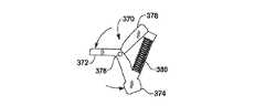
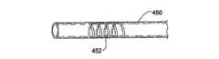
好ましくは、制御ロッドが、制御ハンドルから細長いシャフトの遠位端まで伸長し、制御アクチュエータの動きを顎の動きに変換するように接続される。一構成では、力制限機構は、制御ロッドに同軸に取り付けられたバネを備える。該バネは、細長いシャフト内に配置されることができ、管状の制御ロッド内の螺旋状のレーザカットのように、該制御ロッドの一部として形成されることもできる。更に、第2のバネが制御ロッドに同軸に取り付けられることができ、該第2のバネは、顎を閉じると、第1および第2のバネの変形が同時に生じないように構成されることができる。第2の構成に従って、力制限構造は、制御ハンドル内に配置されたバネを備える。例えば、制御アクチュエアータは、2つの方向に旋回し、それに応じて該旋回の方向とは反対の方向に制御ロッドを変位させるように軸受けされたトグルを備えることができ、該バネは、トグルの旋回の該2つの方向の一方において、トグルと制御ロッドとの相対的な運動に影響を与えるように構成される。代替的に、力制限機構は、閉じた顎から制御ロッドを通して伝達される所定の反力で、トグルの旋回の該2つの方向の一方において、トグルと制御ロッドとの相対的運動を切り離す(すなわちクラッチする)ように適応されたボールもどり止め(ball detent)構造を含む。 Preferably, a control rod extends from the control handle to the distal end of the elongate shaft and is connected to convert the movement of the control actuator into movement of the jaw. In one configuration, the force limiting mechanism comprises a spring that is coaxially attached to the control rod. The spring can be disposed in an elongate shaft and can be formed as part of the control rod, such as a helical laser cut in a tubular control rod. In addition, a second spring can be coaxially attached to the control rod, and the second spring can be configured such that deformation of the first and second springs does not occur simultaneously when the jaws are closed. it can. According to the second configuration, the force limiting structure comprises a spring disposed in the control handle. For example, the control actuator can comprise a toggle that is pivoted in two directions and correspondingly displaces the control rod in a direction opposite to the direction of the pivot, the spring being In one of the two directions of rotation, it is configured to influence the relative movement of the toggle and the control rod. Alternatively, the force limiting mechanism decouples the relative movement of the toggle and the control rod in one of the two directions of toggle rotation with a predetermined reaction force transmitted from the closed jaw through the control rod (ie, Includes a ball detent structure adapted to clutch).
代替の構成では、力制限機構は、顎に組み込まれた弾性部材を含む。例えば、弾性部材は、高温において変形するように適応されたバイメタリック(bimetallic)のバネである。または、弾性部材は、少なくとも1つの顎上の順応性のある(compliant)層であってもよい。更なる代替構成において、弾性部材は、2つの顎の近位端の間に配置され、顎をさらに閉じる動作を妨げる所定の力で2つの近位端部を分離させることを可能にするバネを備える。 In an alternative configuration, the force limiting mechanism includes an elastic member incorporated into the jaw. For example, the elastic member is a bimetallic spring adapted to deform at high temperatures. Alternatively, the elastic member may be a compliant layer on at least one jaw. In a further alternative configuration, the resilient member is disposed between the proximal ends of the two jaws and includes a spring that allows the two proximal ends to be separated with a predetermined force that prevents further closing of the jaws. Prepare.
一実施形態では、2つの顎は、細長いシャフトの端部に平行に取り付けられ、該装置が、顎の開閉中に該顎の平行性を維持する構造を更に含む。 In one embodiment, the two jaws are mounted parallel to the end of the elongate shaft and the device further includes a structure that maintains the parallelism of the jaws during jaw opening and closing.
本発明の更なる別の側面によれば、目標となる組織を切断すると共に、切断された端部を溶接する手術方法が提供される。該方法は、該目標組織に対して開閉するように構成された対向する表面を持つ1対の顎を有する、組織溶接のための手術用装置を提供するステップを含む。顎の少なくとも1つは、その対向表面上に電気抵抗型の加熱素子を含む。顎は目標組織に対して閉じられ、該顎を閉じる力の大きさは、加熱素子が顎の対向表面内に保持される組織を約5秒以内の時間枠で効率的に切断および溶接するように制御された値に制限される。第1の加熱素子は、目標組織に溶接される領域を形成し、その領域内の目標組織を切断するように通電される。好ましくは、顎を閉じる力の大きさを制限するステップは、約1乃至3ポンド(すなわち0.45乃至1.36キログラム)の間に顎を閉じる力の大きさを制御するステップを含む。さらに、組織を切断するための第2の抵抗型加熱素子が、第1または第2の顎の対向表面に提供され、該方法は、溶接される領域内の目標組織を切断するように第2の加熱素子に電気エネルギーを与えるステップを含む。 According to yet another aspect of the invention, a surgical method is provided for cutting target tissue and welding the cut ends. The method includes providing a surgical device for tissue welding having a pair of jaws having opposing surfaces configured to open and close relative to the target tissue. At least one of the jaws includes an electrically resistive heating element on its opposing surface. The jaw is closed relative to the target tissue, and the magnitude of the force to close the jaw is such that the heating element efficiently cuts and welds the tissue held in the opposing surface of the jaw in a time frame within about 5 seconds. Is limited to a controlled value. The first heating element forms a region to be welded to the target tissue and is energized to cut the target tissue in that region. Preferably, the step of limiting the magnitude of the jaw closing force includes controlling the magnitude of the jaw closing force between about 1 to 3 pounds (ie, 0.45 to 1.36 kilograms). Further, a second resistive heating element for cutting tissue is provided on the opposing surface of the first or second jaw, and the method includes a second so as to cut the target tissue in the area to be welded. Applying electrical energy to the heating element.
該方法は、また、目標組織に対し顎を閉じるステップの間、2つの顎の間の平行性を維持するステップを含む。望ましくは、該手術用装置は、顎を開閉するための制御アクチュエータを有する制御ハンドルを更に含む。一実施形態において、制御アクチュエータと顎の間の構造が、顎を閉じる所定の力において制御アクチュエータと顎の相対的運動を完全に分離する(切り離す)。この場合、該方法は、顎の運動が制御アクチュエータの更なる運動から分離されるように、該所定の閉じる力に達するまで顎を閉じるステップを含む。代替的に、制御アクチュエータと顎の間の構造は、所定の閉じる力において制御アクチュエータと顎の相対的運動に影響を及ぼす。後者の場合、該方法は、顎によって印加される目標組織に対する閉じる力が、制御アクチュエータの更なる運動があっても一定のままにとどまるように、該所定の閉じる力に達するまで顎を閉じるステップを含む。 The method also includes maintaining parallelism between the two jaws during the step of closing the jaws relative to the target tissue. Preferably, the surgical device further includes a control handle having a control actuator for opening and closing the jaws. In one embodiment, the structure between the control actuator and the jaw completely separates (disconnects) the relative movement of the control actuator and jaw at a predetermined force that closes the jaw. In this case, the method includes the step of closing the jaws until the predetermined closing force is reached, such that the jaw movement is separated from further movements of the control actuator. Alternatively, the structure between the control actuator and the jaw affects the relative movement of the control actuator and the jaw at a predetermined closing force. In the latter case, the method comprises the steps of closing the jaw until the predetermined closing force is reached, so that the closing force applied to the target tissue applied by the jaw remains constant even with further movement of the control actuator. including.
本発明の望ましい1つの側面は、遠位端に取り付けられた組織焼灼のための手段を持つ細長いシャフトを備える、組織溶接のための手術用装置である。該シャフトは、ガスの通路のため、その長さに沿った内部経路を有する。制御ハンドルが細長いシャフトに接続され、ガスが制御ハンドルの内部または環境に放出される前にガスをフィルタするため、細長いシャフトの経路を通って近位方向に通過するガスを捕捉するように、受動フィルタが制御ハンドル内に取り付けられる。組織を焼灼する上記手段は、組織に対して閉じる1対の顎を備えることができ、好ましくは、一対の顎のうちの1つは、その上に電気抵抗方の加熱素子を含む。好ましい形態では、細長いシャフトが、上記内部経路に対して開いた、制御ハンドル内に形成された少なくとも1つのポートを持ち、受動フィルタは、該ポートにおいて細長いシャフトの周囲に配置された中空の透過性部材を含む。受動フィルタは、細長いシャフトの周囲において両端を封止され、ポートが換気する部分に隣接する細長い中空キャビティを持つ管状部材を備えることができる。該装置はまた、体腔を吹送(insufflating a body cavity)する手段を更に含み、該体腔内の正圧(positive pressure)が、ガスを、細長いシャフトの内部経路を通って近位方向に移動させる。 One desirable aspect of the present invention is a surgical device for tissue welding comprising an elongate shaft with means for tissue ablation attached to the distal end. The shaft has an internal path along its length for the passage of gas. The control handle is connected to the elongate shaft and passively captures gas that passes proximally through the path of the elongate shaft to filter the gas before it is released into the control handle or into the environment. A filter is mounted in the control handle. The means for cauterizing the tissue can comprise a pair of jaws that are closed to the tissue, preferably one of the pair of jaws includes an electrically resistive heating element thereon. In a preferred form, the elongate shaft has at least one port formed in the control handle that is open to the internal path, and the passive filter is a hollow permeable membrane disposed around the elongate shaft at the port. Includes members. The passive filter may comprise a tubular member having an elongated hollow cavity that is sealed at both ends around the elongated shaft and that is adjacent to the portion where the port ventilates. The device also includes means for insufflating a body cavity, and positive pressure within the body cavity moves the gas proximally through the internal pathway of the elongated shaft.
本発明の更なる代替的な側面は、第1および第2の相対的に可動で、対向する表面を持つ細長い顎を備える、組織を溶接および切断する手術用装置である。相対的に可動な顎は、細長いシャフトの遠位端に取り付けられ、少なくとも1つの加熱素子が、2つの顎のうちの1つの表面上に配置される。制御ハンドルが細長いシャフトに接続され、制御アクチュエータが、細長い顎の対向する表面の分離および接合を交互に実行する。制御ロッドが、制御ハンドルから細長いシャフトの遠位端まで伸長し、制御アクチュエータの動きを顎の動きに変換するように接続される。最後に、制御アクチュエータと顎の間に配置された電動アクチュエータが、制御ロッドを変位させる。 A further alternative aspect of the present invention is a surgical device for welding and cutting tissue comprising first and second relatively movable, elongated jaws having opposing surfaces. A relatively movable jaw is attached to the distal end of the elongate shaft and at least one heating element is disposed on the surface of one of the two jaws. A control handle is connected to the elongate shaft, and a control actuator alternately performs separation and joining of opposing surfaces of the elongate jaw. A control rod extends from the control handle to the distal end of the elongate shaft and is connected to convert the movement of the control actuator into jaw movement. Finally, an electric actuator disposed between the control actuator and the jaws displaces the control rod.
更なる1つの側面において、本発明は、第1および第2の相対的に可動で、対向する表面を持つ細長い顎を備える、組織を溶接および切断する手術用装置を含む。相対的に可動な顎は細長いシャフトの遠位端に取り付けられ、少なくとも1つの加熱素子が該2つの顎のうちの1つの表面に設けられる。制御ハンドルが細長いシャフトに接続され、制御アクチュエータが、細長い顎の対向する表面の分離および接合を交互に実行するため、制御ハンドルに取り付けられる。更に、細長い2つの顎のうちの1つの上の順応性のある層が、顎を閉じる際に変形して、顎を閉じる力の大きさを制限する。1つの構成において、該順応性のある層は、組織に接触する顎の内部に対し、剛性の(rigid)組織接触プレートを備えた、2つの顎のうちの1つに存在する中央層として提供される。顎を閉じる際、剛性な組織接触プレートが、顎の上に浮き、組織にかかる締め付け圧力を均等にするのを助けるように、順応性のある該中央層は、その近位端において比較的大きく圧縮する。代替構成において、順応性層は、2つの顎のうちの1つの組織接触表面を有し、反対の顎が、顎から内側に突き出る加熱素子を含む。顎が閉じる時、該順応性層が、該反対側の顎上の加熱素子の形状に順応する(合致する)ようになる。 In a further aspect, the invention includes a surgical device for welding and cutting tissue comprising first and second relatively movable, elongated jaws having opposing surfaces. A relatively movable jaw is attached to the distal end of the elongate shaft, and at least one heating element is provided on the surface of one of the two jaws. A control handle is connected to the elongate shaft and a control actuator is attached to the control handle for alternately separating and joining opposing surfaces of the elongate jaw. In addition, a conformable layer on one of the two elongated jaws deforms when closing the jaws, limiting the amount of force that closes the jaws. In one configuration, the conformable layer is provided as a central layer present in one of the two jaws with a rigid tissue contacting plate for the interior of the jaw contacting the tissue. Is done. When closing the jaw, the compliant central layer is relatively large at its proximal end so that the rigid tissue contact plate floats over the jaw and helps to equalize the clamping pressure on the tissue. Compress. In an alternative configuration, the conformable layer has a tissue contacting surface of one of the two jaws and the opposite jaw includes a heating element that protrudes inwardly from the jaw. When the jaw is closed, the conformable layer becomes adapted to the shape of the heating element on the opposite jaw.
本発明の更なる側面に従って、組織を溶接する手術用装置は、対向する表面を持つ第1および第2の相対的に可動な、細長い顎を備える。相対的に可動な顎は、細長いシャフトの遠位端に取り付けられ、少なくとも1つの加熱素子が、2つの顎のうちの1つの対向する表面上に設けられる。制御ロッドが、制御ハンドルから細長いシャフトの遠位端まで伸長し、制御アクチュエータの運動を顎の運動に変換するように接続される。最後に、制御ハンドルが細長いシャフトに接続され、制御アクチュエータが、細長い顎の対向する表面の分離および接合を交互に実行するため、制御ハンドルに取り付けられる。制御アクチュエータは、制御ロッドに接続された部材を収容するカム・スロットを含み、該カム・スロットは、非線形レートで制御ロッドを変位させるような形状とされる。好ましくは、カム・スロットは、顎が互いに接合し始めるにつれてその閉じるレートが減少し、顎が開き始めるにつれて分離レートが増加するような形状とされる。 In accordance with a further aspect of the present invention, a surgical device for welding tissue comprises first and second relatively movable elongated jaws having opposing surfaces. A relatively movable jaw is attached to the distal end of the elongate shaft, and at least one heating element is provided on the opposing surface of one of the two jaws. A control rod extends from the control handle to the distal end of the elongate shaft and is connected to convert the movement of the control actuator into a jaw movement. Finally, a control handle is connected to the elongate shaft and a control actuator is attached to the control handle for alternately separating and joining the opposing surfaces of the elongate jaw. The control actuator includes a cam slot that houses a member connected to the control rod, the cam slot being shaped to displace the control rod at a non-linear rate. Preferably, the cam slot is shaped such that its closing rate decreases as the jaws begin to join together and the separation rate increases as the jaws begin to open.
本発明の更なる側面に従って、組織を溶接する手術用装置は、第1および第2の相対的に可動で、対向する表面を持つ細長い顎を備える。相対的に可動な顎は、細長いシャフトの遠位端に取り付けられ、少なくとも1つの加熱素子が、2つの顎のうちの1つの対向する表面に設けられる。制御ハンドルが、細長いシャフトに接続され、制御ハンドルに取り付けられた制御アクチュエータが、細長い顎の対向する表面の分離および接合を交互に実行する。顎の各々は横幅を持ち、該2つの顎のうちの一方は、他方の顎より少なくとも20%小さい横幅を持つ。 In accordance with a further aspect of the present invention, a surgical device for welding tissue comprises first and second relatively movable, elongated jaws having opposing surfaces. A relatively movable jaw is attached to the distal end of the elongate shaft and at least one heating element is provided on the opposing surface of one of the two jaws. A control handle is connected to the elongate shaft, and a control actuator attached to the control handle alternately performs separation and joining of the opposing surfaces of the elongate jaw. Each of the jaws has a width, and one of the two jaws has a width that is at least 20% less than the other jaw.
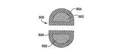
本発明の更なる1つの側面は、第1および第2の相対的に可動な、細長い顎を備えた組織溶接用の手術装置である。これらの顎は、組織に対する耐性(tissue-resistant)を持つブーツ(boot)によって囲まれた内部顎部材を含み、他方の顎に対向する一方の顎の表面上において、該2つのブーツのうちの少なくとも1つのブーツの形状が凸状である。相対的に可動な顎は、細長いシャフトの遠位端に取り付けられ、少なくとも1つの加熱素子が、該2つの顎のうちの1つの対向する表面に設けられる。制御ハンドルが細長いシャフトに接続される。制御アクチュエータが、細長い顎の対向する表面の分離および接合を交互に実行するため、制御ハンドルに取り付けられる。1つの構成において、他方の顎に対向する一方の顎の表面上において、各ブーツの形状は凸状である。好ましくは、両方のブーツが、互いに対向する丸い部分を含む実質的に半円形をした外部表面を持つ。 A further aspect of the present invention is a surgical device for tissue welding with first and second relatively movable elongated jaws. These jaws include an internal jaw member surrounded by a tissue-resistant boot, on the surface of one jaw opposite the other jaw, of the two boots. The shape of at least one boot is convex. A relatively movable jaw is attached to the distal end of the elongate shaft, and at least one heating element is provided on the opposing surface of one of the two jaws. A control handle is connected to the elongated shaft. A control actuator is attached to the control handle to alternately perform separation and joining of the opposing surfaces of the elongated jaw. In one configuration, the shape of each boot is convex on the surface of one jaw opposite the other jaw. Preferably, both boots have a substantially semi-circular outer surface that includes rounded portions facing each other.
本発明の更なる1つの側面に従って、組織を溶接する手術用装置は、第1および第2の相対的に可動で、対向する表面を持つ細長い顎を含む。相対的に可動な顎は細長いシャフトの遠位端に取り付けられ、少なくとも1つの加熱素子が、該2つの顎のうちの1つの対向する表面に設けられる。制御ハンドルが細長いシャフトに接続され、制御アクチュエータが、細長い顎の対向する表面の分離および接合を交互に実行するため、制御ハンドルに取り付けられる。流体的−機械的(fluid-mechanical)駆動機構が、制御アクチュエータと顎の間に接続され、制御アクチュエータの運動を顎の運動に変換する。 In accordance with a further aspect of the invention, a surgical device for welding tissue includes first and second relatively movable, elongated jaws having opposing surfaces. A relatively movable jaw is attached to the distal end of the elongate shaft, and at least one heating element is provided on the opposing surface of one of the two jaws. A control handle is connected to the elongate shaft and a control actuator is attached to the control handle for alternately separating and joining opposing surfaces of the elongate jaw. A fluid-mechanical drive mechanism is connected between the control actuator and the jaw to convert the movement of the control actuator into a movement of the jaw.
本発明の更なる1つの側面は、組織に対する耐性を持つブーツによって囲まれた内部顎部材を含む第1および第2の相対的に可動な、細長い顎を備えた組織溶接用の手術装置である。相対的に可動な顎は、細長いシャフトの遠位端に取り付けられ、少なくとも1つの加熱素子が、第1および第2の顎のうちの1つのブーツに埋め込まれる。制御ハンドルが細長いシャフトに接続され、制御アクチュエータが、細長い顎の対向する表面の分離および接合を交互に実行するため、制御ハンドルに取り付けられる。 A further aspect of the present invention is a surgical device for tissue welding with first and second relatively movable elongated jaws including an inner jaw member surrounded by a tissue resistant boot. . A relatively movable jaw is attached to the distal end of the elongate shaft and at least one heating element is embedded in the boot of one of the first and second jaws. A control handle is connected to the elongate shaft and a control actuator is attached to the control handle for alternately separating and joining opposing surfaces of the elongate jaw.
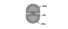
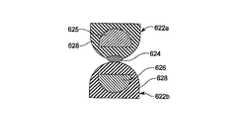
本発明の更なる1つの側面は、第1および第2の相対的に可動で、対向する表面を持つ細長い顎を備えた、組織切断用の手術装置である。相対的に可動な顎は、細長いシャフトの遠位端に取り付けられ、少なくとも1つの加熱素子が、該2つの顎のうちの1つの対向する表面に設けられる。制御ハンドルが、細長いシャフトに接続され、制御アクチュエータが、細長い顎の対向する表面の分離および接合を交互に実行するため、制御ハンドルに取り付けられる。少なく1つのフラップ(flap)が、該2つの顎のうちの1つから突き出て、顎が閉じる時に他方の顎の側面に重なって顎から組織を押すのを助ける。望ましくは、顎の各々は、組織に対する耐性を持つブーツによって囲まれた内部顎部材を備え、ブーツの各々が、反対側の顎の側面に重なり合うように突き出たフラップを含む。 A further aspect of the present invention is a surgical device for tissue cutting comprising first and second relatively movable, elongated jaws having opposing surfaces. A relatively movable jaw is attached to the distal end of the elongate shaft, and at least one heating element is provided on the opposing surface of one of the two jaws. A control handle is connected to the elongate shaft and a control actuator is attached to the control handle for alternately separating and joining opposing surfaces of the elongate jaw. At least one flap protrudes from one of the two jaws and assists in pushing tissue from the jaw over the side of the other jaw when the jaw is closed. Desirably, each of the jaws includes an inner jaw member surrounded by a tissue resistant boot, each of the boots including a flap protruding to overlap the side of the opposite jaw.
本発明の更なる側面に従って、第1および第2の相対的に可動で、対向する表面を持つ細長い顎を備えた、組織溶接用の手術装置が提供される。相対的に可動な顎は、細長いシャフトの遠位端に取り付けられ、少なくとも1つの加熱素子が、該2つの顎のうちの1つの対向する表面上に設けられる。制御ハンドルが細長いシャフトに接続され、制御アクチュエータが、細長い顎の対向する表面の分離および接合を交互に実行するため、制御ハンドルに取り付けられる。制御ハンドルは、顎が閉じられる時に、制御アクチュエータの運動の範囲において、制御アクチュエータの運動を一時的にロックする構造を含む。好ましくは、制御アクチュエータは、制御ハンドル内の旋回運動に適応されたトグルを備える。トグルの運動を一時的にロックする構造は、制御ハンドル内に形成されたL字形経路にはまるトグル上のピン、および、角度を付けられた短い経路部分に向けてトグルをバイアスさせるバネを備える。代替的に、トグルの運動を一時的にロックする構造は、制御ハンドル内に固定されたピンに係合するトグル上の機能を含む。 In accordance with a further aspect of the present invention, there is provided a surgical device for tissue welding comprising first and second relatively movable, elongated jaws having opposing surfaces. A relatively movable jaw is attached to the distal end of the elongate shaft, and at least one heating element is provided on the opposing surface of one of the two jaws. A control handle is connected to the elongate shaft and a control actuator is attached to the control handle for alternately separating and joining opposing surfaces of the elongate jaw. The control handle includes a structure that temporarily locks the motion of the control actuator in the range of motion of the control actuator when the jaw is closed. Preferably, the control actuator comprises a toggle adapted for pivoting movement in the control handle. The structure that temporarily locks the movement of the toggle includes a pin on the toggle that fits into an L-shaped path formed in the control handle and a spring that biases the toggle towards the angled short path section. Alternatively, the structure that temporarily locks the movement of the toggle includes a function on the toggle that engages a pin secured within the control handle.
本発明の更なる側面は、第1および第2の相対的に可動で、対向する表面を持つ細長い顎を備えた、組織切断用外科装置を提供する。相対的に可動な顎は、細長いシャフトの遠位端に取り付けられ、少なくとも1つの加熱素子が、顎の開いている時に組織を切開するため、該2つの顎のうちの1つの対向する表面上に設けられる。制御ハンドルが細長いシャフトに接続され、制御アクチュエータが、細長い顎の対向する表面の分離および接合を交互に実行するため、制御ハンドルに取り付けられる。制御ロッドが、制御ハンドルから細長いシャフトの遠位端まで伸長し、制御アクチュエータの運動を顎の運動に変換するように接続される。制御アクチュエータは、制御ロッドに作用するカム・ローブを含む。カム・ローブは、1つの方向に変位させられる時に、顎をその最大幅に開き、次いで、顎を若干閉じて、切断機能の向上のために一方の顎の角度を他方の顎に対して制御するような形状を持つ。 A further aspect of the present invention provides a tissue cutting surgical device comprising first and second relatively movable, elongated jaws having opposing surfaces. A relatively movable jaw is attached to the distal end of the elongate shaft, and at least one heating element is on the opposing surface of one of the two jaws for incising tissue when the jaw is open. Is provided. A control handle is connected to the elongate shaft and a control actuator is attached to the control handle for alternately separating and joining opposing surfaces of the elongate jaw. A control rod extends from the control handle to the distal end of the elongate shaft and is connected to convert the movement of the control actuator into a jaw movement. The control actuator includes a cam lobe that acts on the control rod. The cam lobe, when displaced in one direction, opens the jaw to its maximum width, then closes the jaw slightly and controls the angle of one jaw relative to the other jaw for improved cutting function It has a shape to do.
本発明の最後の側面は、第1および第2の相対的に可動で、対向する表面を持つ細長い顎を備えた、組織溶接用の手術装置を提供する。相対的に可動な顎は、細長いシャフトの遠位端に取り付けられ、少なくとも1つの加熱素子が、顎が開いた時に組織を切開するため、該2つの顎のうちの1つの対向する表面上に設けられる。制御ハンドルが細長いシャフトに接続され、制御アクチュエータが、細長い顎の対向する表面の分離および接合を交互に実行するため、制御ハンドルに取り付けられる。該装置は、更に、加熱素子を通電するための回路を含む。該回路は、顎を十分閉じるため、制御アクチュエータの運動に応じて作動される安全インターロック(interlock)スイッチを持つ。望ましくは、安全インターロックスイッチは、制御ハンドル内に取り付けられた導電性パッドと接触する制御アクチュエータに取り付けられた少なくとも1つの別の導電性パッドを備える。代替的に、安全インターロックスイッチは、制御アクチュエータの運動の経路において制御ハンドル内に取り付けられたスイッチ、たとえばマイクロ・スイッチである。 The final aspect of the present invention provides a surgical device for tissue welding comprising first and second relatively movable, elongated jaws having opposing surfaces. A relatively movable jaw is attached to the distal end of the elongate shaft, and at least one heating element is on the opposing surface of one of the two jaws for incising tissue when the jaw is opened. Provided. A control handle is connected to the elongate shaft and a control actuator is attached to the control handle for alternately separating and joining opposing surfaces of the elongate jaw. The apparatus further includes a circuit for energizing the heating element. The circuit has a safety interlock switch that is activated in response to the movement of the control actuator to close the jaw sufficiently. Desirably, the safety interlock switch comprises at least one additional conductive pad attached to a control actuator that contacts a conductive pad attached within the control handle. Alternatively, the safety interlock switch is a switch, for example a micro switch, mounted in the control handle in the path of movement of the control actuator.
本発明の1つの側面に従って、手術中に組織を封止、凝固および切断するための装置および方法が提供される。該装置は、組織の加熱を制御しながら同時に、一定の制御可能な量の圧力を該加熱されている組織に印加する手段を含む。熱と圧力の組み合わせられた印加により、組織のタンパク質が凝固され、組織中の血管が閉じられ、その結果止血が達成される。組織の最適な封止または凝固は、組織の副次的な損傷を最小限にとどめながら強くて耐性のある封止、凝固または吻合を生成することを意味する。 In accordance with one aspect of the present invention, devices and methods are provided for sealing, coagulating and cutting tissue during surgery. The apparatus includes means for applying a controllable amount of pressure to the heated tissue while simultaneously controlling the heating of the tissue. The combined application of heat and pressure coagulates tissue proteins and closes blood vessels in the tissue, resulting in hemostasis. Optimal sealing or coagulation of tissue means creating a strong and resistant seal, coagulation or anastomosis while minimizing collateral damage to the tissue.
本発明の1つの側面は、生物学的組織の外科治療のための方法およびシステムを含む。この方法およびシステムにおいて、出血を凝固し、組織を封止し、組織を結合し、組織を切断するという目的のため、タンパク質が変性して組織がそれ自体または他の組織に付着または結合するこのできるような時間にわたって、熱エネルギーと圧力とが同時にまたは実質的に同時にまたは交互に印加される。このような目的を達成するために必要とされる熱または熱エネルギーの最小量は、処置されている組織に隣接する組織に対する熱損傷を最小限にとどめるように定められる。 One aspect of the present invention includes methods and systems for surgical treatment of biological tissue. In this method and system, the protein is denatured and the tissue attaches or binds to itself or other tissue for the purpose of coagulating bleeding, sealing tissue, joining tissue, and cutting tissue. Over as long as possible, thermal energy and pressure are applied simultaneously or substantially simultaneously or alternately. The minimum amount of heat or thermal energy required to achieve such objectives is determined to minimize thermal damage to the tissue adjacent to the tissue being treated.
また、本発明の装置は、組織を切断する手段を含むこともできる。"切断(serving)"は、血管またはリンパ細胞のような他の組織構造の凝固、止血あるいは封止または組織結合との組み合わせにおいて、解剖すなわち組織分割、組織破壊すなわち分離、あるいは組織構造の面展開(plane development)、定義、流動化(mobilization)を含む。切断は、組織を凝固させるために必要な量より多い熱量の使用によって達成されることができるが、望ましくない組織死滅の量を最小にするように最小限のエネルギーが使用される。本発明の別の側面に従って、切断は、他の機械的、超音波的、あるいは電子的手段によって達成されることができる。この手段は、限定的ではないが、はさみ切り動作(shearing action)、レーザ・エネルギー、RF、またはそれらの2つ以上の組み合わせを含む。例えば、組織が装置の顎に保持されている間に、凝固された組織に刃が通される。 The apparatus of the present invention can also include means for cutting tissue. “Serving” is a combination of clotting, hemostasis or sealing or tissue bonding of other tissue structures such as blood vessels or lymphocytes, dissection or tissue division, tissue destruction or separation, or surface development of tissue structures. (plane development), definition, including mobilization. Cutting can be accomplished by the use of a greater amount of heat than is necessary to coagulate tissue, but minimal energy is used to minimize the amount of undesired tissue death. In accordance with another aspect of the invention, cutting can be accomplished by other mechanical, ultrasonic, or electronic means. This means includes, but is not limited to, a shearing action, laser energy, RF, or a combination of two or more thereof. For example, a blade is passed through the coagulated tissue while the tissue is held in the jaws of the device.
本発明は、好ましくは、統合された血管採取システム(たとえば、2004年9月28日付米国特許出願第10/951,426号に開示されており、ここで参照により取り入れられる)の一つのコンポーネントとして組み込まれることができる組織溶接器を提供する。血管採取システムは、最小限の侵襲的(invasive)な内視鏡血管採取において特に有用であり、このシステムは、冠状動脈バイパス移植(coronary artery bypass grafting)における使用のための内胸動脈または腕の撓骨動脈に沿った四肢(extremities)の血管の採取、および冠状動脈バイパス移植および末梢動脈バイパスの両方における使用のための足の伏在静脈の採取を含む。このような観点から、この組織溶接器は、採取されつつある目標血管から側枝分岐部分(side branches)を分離する際に切断および保全(securing)/溶接機能の両方を実施する。しかしながら、理解されるべき点であるが、本明細書に記述されている組織溶接器の種々の側面は、組織の凝固や切断を行う他の手術システムと連係して利用することもできる。 The present invention is preferably incorporated as one component of an integrated vascular collection system (eg, disclosed in US patent application Ser. No. 10 / 951,426, Sep. 28, 2004, incorporated herein by reference). Provide a tissue welder that can. The vascular collection system is particularly useful in minimally invasive endoscopic vascular collection, which can be used in internal thoracic arteries or arms for use in coronary artery bypass grafting. Includes the collection of extremities blood vessels along the radial artery and the saphenous vein of the foot for use in both coronary artery bypass grafts and peripheral artery bypass. From this point of view, the tissue welder performs both a cutting and securing / welding function in separating the side branches from the target vessel being harvested. However, it should be understood that the various aspects of the tissue welder described herein can also be utilized in conjunction with other surgical systems that coagulate or cut tissue.
本発明の組織溶接器の典型的な実施例は、採取されつつある主要血管から側枝分岐部分を切り離し、場合によっては主要血管を切断するために使用されるいわゆる"溶接および切断装置"を含む。しかしながら、本明細書に記述される装置は、単に血管ではなく一般的に組織を溶接したり切断するのに適している。最も広い意味において、組織溶接および切断装置という用語は、目標組織を溶接、結紮(ligating)、焼灼(cauterizing)、凝固および/または封止、切断、または横に切開する(transect)という機能のうちの一つまたはいずれかの機能の組み合わせを実行する装置のいずれかまたはすべてを意味する。例えば、双極の鋏(あるいは他の複数電極型の装置)のような電気焼灼器ツール、単極装置、組織バイセクタ(bisector)、あるいは他のそのような装置が、単独であるいは組み込み刃またはカッターと連係してそのような機能を提供する。組織を封止するため種々の許容可能なエネルギー源(例えば、RF、マイクロ波、レーザ、超音波、直接の熱エネルギーなど)を使用する他の類似の装置もまた、本発明の範囲内にある。組織に作用して溶接または切断する装置の各々は、エネルギー印加器と呼ばれる。溶接および切断装置は、単一のツールでもうよいし、あるいは独立した複数のツールの組み合わせでもよい。各ツールは、組織切断において、特に血管採取において、有用な独自の機能を有する。 An exemplary embodiment of the tissue welder of the present invention includes a so-called “welding and cutting device” that is used to separate the side branch bifurcation from the main blood vessel being harvested and possibly cut the main blood vessel. However, the devices described herein are generally suitable for welding or cutting tissue, not just blood vessels. In the broadest sense, the term tissue welding and cutting device refers to the function of welding, ligating, cauterizing, coagulating and / or sealing, cutting, or transecting the target tissue. Means any or all of the devices that perform one or any combination of functions. For example, electrocautery tools such as bipolar scissors (or other multi-electrode type devices), monopolar devices, tissue bisectors, or other such devices, alone or with built-in blades or cutters Work together to provide such functionality. Other similar devices that use various acceptable energy sources (eg, RF, microwave, laser, ultrasound, direct thermal energy, etc.) to seal tissue are also within the scope of the present invention. . Each device that acts on the tissue to weld or cut is called an energy applicator. The welding and cutting device may be a single tool or a combination of multiple independent tools. Each tool has a unique function useful in tissue cutting, especially in blood vessel harvesting.
ただし、注意すべき点であるが、本発明の種々の側面の各々は、他の側面と連係して使用することができるが、各側面は、従来システムおよび従来技術に関連して単独で使用される場合でも、発明上の意義を有するものと信じられる。かくして、本明細書に記述される以外の加熱および制御構造を使用し、また、血管採取のため以外のシステムにおいて、本発明に従った組織溶接器および方法を実現することができる。更に、本明細書に記述の組織溶接器の種々の側面は、双極挟みまたは組織バイセクタのような他の溶接および切断装置と共に使用することができる。同様に、組織溶接器の凝固機能の側面は、切断機能を提供するため機械的カッターと組み合わせることもできる。 It should be noted, however, that each of the various aspects of the present invention can be used in conjunction with other aspects, but each aspect is used alone in connection with conventional systems and techniques. Even if done, it is believed to have invention significance. Thus, tissue welders and methods according to the present invention can be implemented in systems other than for blood vessel collection using heating and control structures other than those described herein. Further, the various aspects of the tissue welder described herein can be used with other welding and cutting devices such as bipolar scissors or tissue bisector. Similarly, the solidification function aspect of the tissue welder can also be combined with a mechanical cutter to provide a cutting function.
最後に、本明細書に記述される例示的および/あるいは代替的な組織溶接器は、血管採取の他に数多くの用途を備えている点は理解されるべきである。例えば、組織溶接器は、胃の一部を切除して閉じるため胃のバイパス手術で使用されることができる。同様に、気腫患者の肺の容量減少もまた、本明細書記述の装置を用いて達成することができる。腸切除術もまた、別の潜在的に利用可能な面である。その他の外科治療は、大腿膝窩部バイパス、胃食堂逆流症のための上腹部動脈の切断/結紮、ファロピウス管の結紮、精管切除、胆嚢切除術における動脈、静脈および胆管の切断/結紮、および、腎臓に繋がる尿管の切開および結紮における腎摘出、を含む。 Finally, it should be understood that the exemplary and / or alternative tissue welders described herein have numerous applications in addition to blood vessel harvesting. For example, tissue welders can be used in gastric bypass surgery to excise and close a portion of the stomach. Similarly, lung volume reduction in emphysema patients can also be achieved using the devices described herein. Enterectomy is another potentially available aspect. Other surgical treatments include femoral popliteal bypass, upper abdominal artery amputation / ligation for gastroesophageal reflux disease, fallopian tube ligation, vasectomy, arterial, vein and bile duct amputation / ligation in cholecystectomy, And incision of the ureter leading to the kidney and nephrectomy in ligation.
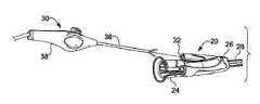
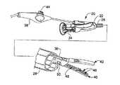
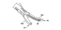
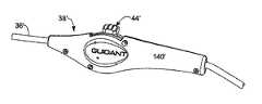
図1のA乃至Cは、契合ハンドル台座(mating handle base)22およびハンドルそり(handle sled)24を有する例示的な血管採取システムのモジュール型ハンドル・ユニット20を示す。ハンドル台座22は、細長いカニューレ28に固定された遠位フランジ26を含む。カニューレ28は、体腔(body cavity)に伸長できる大きさに定められ、種々の血管採取ツールのための経路を提供する。図1Aに見られるように、ハンドルそり24は、ハンドル台座22に契合するための構造を含む。種々のモジュール型ハンドル・ユニットおよび血管採取システムが、前述の2004年9月28日付米国特許出願第10/951,426号に例示され記述されている。 FIGS. 1A-1C show a
図1のA乃至Cの特定の実施形態において、ハンドルそり24が、いくつかの血管採取システムに共通の多目的ハンドル台座のためのアダプタの役割を提供するので、本発明の組織溶接および切断装置30を、該システム内の血管採取のため使用することができる。具体的には、ハンドルそりすなわちアダプタ24は、内部の角度のある経路34に至るポート32を備える。この経路34を通して、溶接および切断装置30の細長いシャフト36が伸長できる。細長いシャフト36が遠位フランジ26および採取カニューレ28を通って導かれるように、ハンドル台座22とハンドルそり24が契合する。図1Cに見られるような最終アセンブリは、採取ツールに関するいくつかの運動制御部品がハンドル・ユニット20に配置され、一方、そり24に対して手でハンドル38全体を操作することによって溶接および切断装置30の回転が達成されることを示している。 In the particular embodiment of FIGS. 1A-C, the
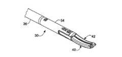
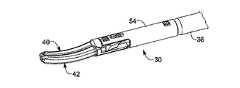
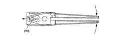
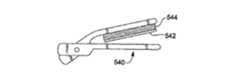
図1Cは、また、カニューレ28の拡大された遠位端を示し、該遠位端から、組織溶接および切断装置30が突き出ている。装置30は、その遠位端上に、相対的に動くことができる1対の細長い顎(jaw)40、42(図では開いて示されている)を備える。好ましくは、ハンドル38内部の機構は、顎40、42を開閉するアクチュエータ44を含む。顎40、42は、直交軸または横断軸のいずれよりも近位−遠位方向が長くなるように、おおむね近位−遠位方向に細長くなっている。 FIG. 1C also shows an enlarged distal end of the
理解されるべき点であるが、"顎"という用語は、他の同様の部材または他の構造と一緒になって用いられる部材であり、これにより、該両方の部材の対向する表面が接触または近接することができる。顎は、締金(クランプ)、ピンセット、鉗子あるいは類似の把持ツール上に提供されることができる。顎40、42は、それらの近位端が、共通の旋回軸または異なっていてもわずかな間隔で配置された旋回軸に軸受けされ、それらの遠位端が開閉するように、取り付けられる。当然のことながら、旋回動作ではなく平行運動するように顎を取り付けてもよい。本発明の実施例は、"熱い"顎と"冷たい"顎を含む。相違は、一方の顎だけが能動的に加熱されるという点である。しかしながら、両方の顎が熱いことも、また分離した熱源を備えて両方の顎が冷たいというような異なる顎構成にも、本発明の側面が適用可能である点は留意されるべきである。 It should be understood that the term “jaw” is a member used in conjunction with other similar members or other structures so that the opposing surfaces of both members are in contact or Can be close. The jaws can be provided on clamps, tweezers, forceps or similar gripping tools. The
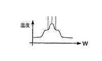
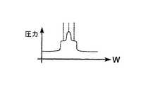
好ましい実施形態において、第1の顎40が"熱い"顎で、第2の顎42が"冷たい"顎である。"熱い(hot)"という用語は、当該顎に少なくとも1つの能動的な加熱素子が備わっていることを意味し、一方、"冷たい(cold)"顎は、能動的な加熱手段を持たない(ただし他方の顎からの間接的加熱によって熱くなることはある)。本実施例において、図1Cに示されているように、第1の"熱い"顎40は、組織を溶接するための第1の加熱素子46および組織を切断するための第2の加熱素子48を含む。第1の加熱素子46は、電流の印加とともに第1の温度まで上昇するように構成され、一方、第2の加熱素子48は、電流の印加とともに第1の温度より高い第2の温度まで上昇するように構成される。従来からの理解に従えば、血管組織が100℃を超えて加熱されると、組織は破壊し、従って"切断(cut)"される。しかしながら、血管組織が50℃から90℃の間の温度に加熱される場合、組織は、単に隣接組織に"封止"され、すなわち"溶接"される。 In a preferred embodiment, the
第1の加熱素子46が溶接温度領域内まで加熱するが、切断温度しきい値までは上昇せず、一方、第2の加熱素子48が溶接温度領域を超えて切断温度領域まで上昇することを確実にする種々の手段が、本明細書において記述される。例えば、第1および第2の加熱素子46、48が異なる温度に上昇するように、それらの相対的な電気抵抗値を設定することができる。代替的に、使用される材料は同じとしても、異なる加熱温度となるように第1および第2の加熱素子46、48の形状を変えることもできる。更に、2つの加熱素子を通る電流を異なるものにしてもよい。 The
図1Cは、また、顎40、42、および細長いカニューレ28の遠位端を通って伸長するシャフト36の遠位端の構成を基本的に示している。特に、顎40、42は、旋回軸(ピボット)ピン50として表されている共通軸の周りを旋回するように配置されている。顎40、42を開閉する機構の例の詳細は後述される。顎40、42の各々は、剛性の材料の内側顎部材と共に、該内部顎部材を取り囲み、該装置の操作中に組織の粘着性に抗するような材料からなるブーツ52a、52b(図3A参照)を含む。1つの実施形態において、内部顎部材は、ステンレス鋼から作られているが、放熱(heat sink)の少ない他の材料を使用することもできる。ブーツ52a、52bは耐熱のシリコーン・ゴムから作製される。ブーツ52a、52bは、また、熱損失を減らすため、内部顎部材の周囲に断熱機能を提供する。第1および第2の加熱素子46、48は、第1の顎40上で、特に第2の顎に対向する第1の顎40の表面上で、ブーツ52aに外付けされる。 FIG. 1C also basically shows the configuration of the distal end of
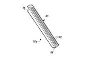
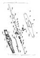
図2乃至図7は、本発明の実施例である組織溶接および切断装置30の遠位端の組み立て、分解およびその他部分に関する図面を示す。図2のAおよびBにおいて、顎40、42は、溶接および切断装置30の遠位端において閉じられている。装置30は、装置シャフト36の端部に取り付けられるおおむね管状の形状をした遠位先端部54を含み、顎40、42を開閉するための機構(後述)を収納している。両方の顎40、42は、双方の顎の対向するそれぞれの表面が曲線に沿って接触するように、それぞれの長さ方向に沿って浅い湾曲を示す。好ましい実施形態において、顎40、42を含む装置30の遠位部全体のアセンブリは、組織の侵襲が最小限の手術となるように、直径5mmのポートを通ることのできる寸法とされる。 2-7 show drawings relating to assembly, disassembly and other parts of the distal end of the tissue welding and cutting
顎40、42は、好ましくは、"熱い"顎40上に複数の加熱溶接システムを組み入れる。最小限、少なくとも2つの加熱素子が設けられる。そのうちの1つは、組織を切断するように構成され、他の加熱素子は、組織を溶接または凝固させるように構成される。1つの実施例において、顎40は"3つの加熱素子"の構成を持ち、この場合、1つの加熱素子が切断のためのもので、他の2つが、切断素子の両側に配置されて溶接機能を提供する。望ましくは、これらの加熱素子は、顎40の遠位端に近い方から長軸方向に伸長し、切断加熱素子がおおむね中央に、2つの溶接加熱素子が、その両側に対称的に配置される。 The
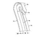
図3のAおよびBは、開いた時の顎40、42を示す。図3のBに見られるように、好ましくは、第1の加熱素子46は、横方向に分離された2つの溶接部材に分岐し、それら両方の部材の間に、単一の第2の加熱素子48が配置される。第1の加熱素子46の分岐した溶接部材の各々が、組織内に溶接領域を提供し、一方、第2の加熱素子が、その溶接領域内の組織を切断する。従って、技術的に見れば、熱い顎40は、1つの中央切断素子とそれに隣接する2つの溶接素子という3つの加熱素子を含む。本実施例では、2つの隣接する溶接素子を一体的に結合しているが、それらを独立するように構成することも容易にできるであろう。上述のように、顎40、42の一方または両方は、ブーツ(boot)52a、52bによって囲まれた内部顎部材を含む。第2の顎42の周りのブーツ52bは、好ましくは、把持機能を提供すると共に、組織が2つの顎に挟まれた時に該組織が滑るのを防止するための、横方向の一連ののこぎり歯60を備える。第1の顎40のブーツ52aの外側には、第1および第2の加熱素子46、48が配置されているので、第1のブーツ52aにはそのような歯は不要である。 3A and 3B show the
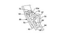
図4は、分解された装置30の遠位端のコンポーネントを示し、図5乃至図7は、第1および第2の加熱素子46、48の具体的な形状と半組立部品、およびそれらの第1の顎40への取り付け様態を示す。第1の"熱い"顎40の内部顎部材62(図8のAおよびBに別掲)は、細長く曲がった遠位部分64および近位旋回軸格納体66を備える。格納体66には、他方の顎に対する旋回運動のための通し孔が備えられる。より具体的には、内部顎部材62の近位旋回軸格納体66は、大きい円状の通し孔67および角度のついたスロット68を含む。これらは共に、外壁部分69に形成される。外壁部分69から直立する一対の側壁70が、以下に記述するように、その内部に電線および旋回軸機構が収容される旋回軸格納体66の内側の空間を提供する。 4 shows the components at the distal end of the disassembled
第1の加熱素子46は、近位クリンプ(crimp)72およびフランジ73を備える。2つの細長い溶接部材74が、近位クリンプおよびフランジから遠位方向に伸長し、上に曲がって戻りながら共通鉤(barb)75に至る(図7のB参照)。細長い溶接部材74は、好ましくは、それぞれが横幅Wを持つ薄い長方形ストリップであって、互いに間隔Sを置いて平行に伸長する長方形ストリップから構成される。2つの溶接部材74が、クリンプ72およびフランジ73によって近位端において、また、共通鉤75によって遠位端において、接続されているので、それらが、第1の加熱素子46の分岐部分を画定する。好ましい実施形態において、第1の加熱素子46は、型打ち(stamping)、屈曲(bending)、機械加工等々によって図示の形状に形成される単一で同質の金属(例えば、ステンレス鋼)から構成される。 The
第2の加熱素子48は、間隔を置いた2つの溶接部材74の間をそれらに平行して伸長するが、該溶接部材とは空隙によって分離される。加熱素子48もまた、溶接部材74と同じ長さだけ遠位方向に伸長し、上に曲がって戻りながら共通鉤75に隣接する接続端部76に至る(図7のB参照)。接続端部76と鉤75とは、例えば抵抗溶接すなわちスポット溶接を使用して電気的に接続される。本明細書の記述において、2つの機械的部品の間の接続を記述するために使用される用語"抵抗溶接(resistance weld)"は、例えば、スポット(spot)溶接、レーザ溶接、はんだ付け接続、ろう付け結合(brazed joint)などを含むすべての適切な結合形態を包含する。 The
図4の分解組立図に見られるように、加熱素子48は、細長いワイヤーすなわちロッドから構成されることができ、接続端部76を、連続した伸長部を形成する別個のU字形結合部77によって形成することができる。第2の加熱素子48は、第1の加熱素子46と比較して、第2の顎42に向かう方向に隆起するような形状となっている。これにより、第1の加熱素子46が溶接を行っている間に、第2の加熱素子48が組織を切断する、という異なる機能を果たすことができる。更に、第1の加熱素子46のストリップ状溶接部材74の各々は、平坦な、顎に対向する表面を持ち、一方、第2の加熱素子は、溶接部材のいずれよりも小さい横方向の幅を持つ円筒状の、顎に対向する表面を画定する。 As seen in the exploded view of FIG. 4, the
第1の加熱素子46の1つの例が、図9のA乃至Eに別個に示されている。これの図は、上記引用の図に示されたものと若干異なる加熱素子46を示しているが、いずれを使用しても望ましい結果を生む。相違は遠位端にあり、近位端方向に鉤75に巻き戻る構成の代わりに、本実施例では、たとえば90°に曲げられたフランジ78が示されている。フランジ78は、第2の加熱素子48を収容するようにおおむね半円の開口部80を規定するように、フォーク状に構成されている。図示されてはいないが、この場合、第2の加熱素子48は、開口部80に180°カールし、例えば抵抗溶接を使用して該開口部に電気的に接触するように固定される。 One example of the
ここで図5乃至図7を特に参照すると、直列回路を形成するために取り付けられた複数の導線を有するように、加熱素子46、48が示されている。図6Bおよび図7Aに示されているように、絶縁された一対の導線82、84は、加熱素子46、48を通る回路経路の一部を形成する。第1の導線82は、近位クリンプ72における抵抗溶接によって第1の加熱素子46と電気的に接触し、第2の導線84は、第2の加熱素子48と電気的に接触する。第2の導線84の周囲の絶縁されたスリーブが、第1の加熱素子46のフランジ73に形成された開口部を通って伸長する。第1および第2の加熱素子46、48が顎40の長さ全体に沿って電流ループを画定するように、鉤75と接続端部76とは電気的に接触する。 With particular reference now to FIGS. 5-7, the
こうして、導線82、84を通る電流が第1および第2の加熱素子46、48を直列に通る。第1および第2の加熱素子46、48を通る電流は、それらの共通遠位端までは、具体的には鉤75と接続端部76の間の抵抗溶接部までは、分離されたままである。第1の加熱素子46が2つの分離した溶接部材74に分岐するという構成により、溶接部材74の各々は、第2の加熱素子48に流れる電流のほぼ半分を並列に通す。従って、これらの加熱素子が形状および材料の点で同一であれば、溶接部材74の各々は、電流が分岐されているので、第2の加熱素子74が達する温度より低い温度までしか上昇しないことは理解されるであろう。この差により、第1の加熱素子46が溶接領域の温度に到達し、一方、第2の加熱素子48が切断領域の温度に到達することが保証される。本実施形態において、別個の溶接部材74の各々は、顎40の長さ方向を横切る平面において組織に対向する表面領域であって、第2の加熱素子48より幅広い表面領域を有する。比較的低い電流、よって比較的低い温度とあいまって、このような第1の加熱素子の構造が、幅がより狭くより熱い(そして比較隆起されている)中央の加熱素子48とは対照的に、切断動作とは反対の組織溶接動作の実行を容易にする。 Thus, the current through the
しかしながら、第2の加熱素子48は、溶接部材74のいずれよりも高い電気的抵抗を持つように構成されているので、なお一層大きな電流でさえも更に多く熱として放散させるという利点を持つ。このような一層高い電流と一層高い抵抗との組み合わせによって、第1の加熱素子46が組織溶接領域にとどまりつつ、第2の加熱素子48が切断領域温度まで上昇することを可能にする。好ましい実施形態において、第1の加熱素子46は、301ステンレス鋼のような適切な導電性金属で製作され、一方、第2の加熱素子48は、ステンレス鋼より大きい電気抵抗を持つように、剛性の材料のチューブと該チューブより電気抵抗の大きい充填材という組み合わせで構成される。1つの具体的な実施形態において、該チューブは、INCONEL 625のようなニッケル−クロム合金から作られ、マグネシウム酸化(MgO)粉末のような電気的に絶縁されているが熱伝導性のあるセラミックが該チューブに充填される。従って、固体(solid)である場合より一層大きい電流密度が該中空チューブを通過し、その結果、該材料は、所与の電流において一層高い温度に達する。加えて、内部の熱伝導性セラミックは、素子48を通る伝導性の熱流(conductive heat flow)を不当に制約しない。好ましくは、第2の加熱素子48は約0.2オームという相対的に高い抵抗を持ち、第1および第2の加熱素子からなるシステム全体は約0.72オーム、好ましくは0.8オーム未満の平均抵抗を持つ。 However, since the
理解されるべき点であるが、本発明は、少なくとも1つの切断素子および少なくとも1つの溶接素子を意図しているが、それらは電気的に直列していてもいなくてもよい。例えば、例示されている実施形態は、1つが第1の(溶接)加熱素子46における使用のため、別の1つが第2の(切断)加熱素子48での使用のためという2つの電流経路を利用することによって変更されることもできる。代替的に、1つの切断素子および単一の(すなわち分岐されてない)溶接素子を熱い顎上に備え、両者が共通の電流経路の一部を形成するように構成することもできる。また、これと同じ構成において、別々の電流経路を持つようにしてもよい。更に、上述のように、切断素子を1つの顎上に配置し、溶接素子を反対の顎上に配置することもできる。このような代替構成の各々において、電流経路が共通であろうと別々であろうと、切断素子が溶接素子より高い温度に達するという点は共通した特徴である。 It should be understood that although the present invention contemplates at least one cutting element and at least one welding element, they may or may not be in electrical series. For example, the illustrated embodiment provides two current paths, one for use in the first (welding)
図10のA乃至Fは、"熱い"顎40に使用されるブーツ52aの1つの例をいくつかの方向から示している。上述のように、ブーツ52aは、組織の粘着(付着)に耐性のあるシリコーン・ゴムのような材料で作製されており、そのような組織付着のために顎の効率が低下するに先立ち、複数の組織切断/溶接手術を実施することを可能にする。ブーツ52aは、加熱素子46、48の間の電気的絶縁および断熱を提供するので、一般に金属でできている内部顎62では熱が失われるのに対し、両方の顎の間の空間で熱を保持するのに役立つ。ブーツ52aは、一般に、開いた近位端86および部分的に閉じた遠位端88を持つ中空スリーブから構成される。ブーツ52aが熱い顎40に取り付けられる場合、冷たい顎42に対向する上部表面90が、長さ方向の1対のレール92を含む。図10のDおよびGに見られるように、2つのレール92は、おおむね等間隔に配置され、2つに分岐した第1の加熱素子46および中央の第2の加熱素子48に対する案内経路を提供する。ブーツ52aの遠位端88は開口部を持ち、その中に、2つの加熱素子46、48の結合されカールされた(曲げられた)遠位端が伸長する。これによって、2つの電極の遠位端が熱い顎上に保持される。留意されるべき点であるが、内部顎部材62の遠位端は、図7のCにおいて符号93で示されるように、フォーク状に分岐している。ブーツ52aは、このような形態に整合するような内部形状を持ち、結合された鉤75および接続端部76を収容するため外側に開いた窪み(キャビティ)を提供するように、成形される。鉤75の矢じり形状が、好ましくはシリコーン・ゴムでできている柔らかい絶縁ブーツ52aに対して加熱素子が適切な位置に固定されることを保証するのに役立つ。 FIGS. 10A-F show one example of a
図5および図6は、組み合わされた加熱素子46、48および導線82、84の内部顎部材62への組み入れを示す。図6のBに見られるように、近位クリンプ72が、第1の加熱素子46およびシリコン・ブーツ52aの伸長部分を、旋回軸格納体66の直立フランジ94に確保している。導線82、84は、旋回軸格納体66内に一対の側壁70によって形成された空間を通るように配線される。第1の導線82は、一方の側壁70に沿ってまっすぐ伸長して、第1の加熱素子46の近位クリンプ72に抵抗溶接またはその他の方法で固定される。第2の導線84は、他方の側壁70に沿って曲がった経路を取り、図6のAに見られるように、第1の加熱素子46の近位フランジ73に形成された前述の開口部を通過する。図5のBは、旋回軸格納体66上に組み立てられた直立シャフトスタブ(stub)98を持つブッシング(bushing,軸受け)96を示す。ブッシング96は、顎40、42を開閉する機構の一部を形成する(詳細は後述)。 FIGS. 5 and 6 illustrate the incorporation of the combined
組み立てを容易にし、製造コストを下げる本発明の1つの側面は、加熱素子サブシステムの組み立て特性である。図6のBおよび図7のAに見られるように、該サブシステムは、第1の加熱素子46、第2の加熱素子48、(典型的には第1の内側顎62と一体的に組み立てられる)旋回軸格納体66、および直列の加熱素子を通る電流を提供する2つの導線82、84、という5つの部品から構成される。これら5つの部品は、いくつかのクリンプで、あるいは望ましくは溶接で、あるいは両方の方法で結合され、熱い顎の残り部分との統合に先立って容易に組み立てられる。 One aspect of the present invention that facilitates assembly and reduces manufacturing costs is the assembly characteristics of the heating element subsystem. As seen in FIG. 6B and FIG. 7A, the subsystem is assembled integrally with a
前述のように、顎40、42のいずれかあるいは両方は、ブーツで覆われた内部顎部材を含む。図4の分解組立図は、熱い顎40の内部顎部材62と第2の冷たい顎42の内部顎部材102の両方を、関連するブーツ52a、52bと共に示している。両方のブーツ52a、52bは、内部顎部材62、102の曲がった遠位端にはまって取り囲む。 As described above, either or both
従来の組織溶接器具においては、ステンレス鋼の内部顎部材は、1つまたは複数の電極を通過する電流のための戻り導電路として便宜的に使用されていた。これには、電流の一部が内部顎部材の内部に生成される抵抗熱として浪費されるという明白な欠点があった。また、加熱素子から顎への熱伝導が、組織への非効率なエネルギー供給を生み、潜在的に不慮の熱損傷をもたらすという欠点もあった。1つの側面において、本発明は、絶縁ブーツ52aが間に挟みこまれているという点において、加熱素子46、48を第1の内側顎部材から物理的に切り離すだけではなく、電流が内部顎部材を通過することはない。遠位鉤75と接続端部76との間の直列接続は、熱い顎に沿った導電経路全体が加熱素子46、48だけを通るということを意味する。このようにして、電気エネルギーの望ましい抵抗熱への変換効率が最大にされ、加熱素子と直接接触する以外の組織に対する該装置の実装面積(footprint)が最小にされる。 In conventional tissue welding instruments, a stainless steel inner jaw member has been conveniently used as a return conductive path for current passing through one or more electrodes. This had the obvious disadvantage that part of the current wasted as resistive heat generated inside the inner jaw member. There was also the disadvantage that heat conduction from the heating element to the jaws resulted in an inefficient energy supply to the tissue, potentially causing inadvertent thermal damage. In one aspect, the present invention not only physically separates the
組織、より具体的には血管を溶接および切断することができる能力に加えて、顎40、42は、筋膜切開手術(fasciotomy)、すなわち筋膜(例えば、組織の異なった層を分離する線維組織(fibrous tissue)の帯(band)すなわちフィレ(fillet))を通る切開を実施する能力を有することができる。開いた顎40、42が示されている図3のBに最もよく見られるように、"カッター・ワイヤ(cutter wire)"である第2の加熱素子48が、顎の中央平面に沿って顎の長さいっぱいに伸長している。加えて、第2の加熱素子48は、取り囲んでいる第1の加熱素子46の溶接部材よりも隆起するように配置されている。これにより、熱い顎の第1の表面が、顎の内部に取り込まれた組織と接触することができる。筋膜切開手術は、切断温度まで上昇した熱によって組織を切断するように通電された第2の加熱素子48を用いて、組織帯を通って開いた顎を単に押し込むことによって実行されることができる。当然のことであるが、本実施例において、第1の加熱素子46も熱くなるが、筋膜切開手術への影響はほとんどない。 In addition to the ability to weld and cut tissue, more specifically blood vessels, the
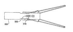
図4は、また、第2の"冷たい"顎42の内部顎部材102の遠位端に配置された先細の先端部103を示している。この先端部103は、組織の非切開抜去(blunt dissection)を容易にするのに役立つ。取り囲むブーツ52bも、同様の先細形状とすることができる。好ましい実施形態において、内部顎部材102は、おおむね長方形の断面を持ち、先端部103は、向かい合う両サイドに設けられた2つの先細部分を持つ。当然のことながら、一層丸い断面や円錐形に先細にされた先端部103も代替的に使用可能である。更に、組織の非切開抜去を一層容易にするため、冷たい顎42の内部顎部材102は、第1の顎40の内部顎部材62に比べて若干長くされる。 FIG. 4 also shows a tapered
組織溶接シャフト36の遠位端への顎40、42の取り付けおよび顎を開閉する機構の例を以下に記述する。図4の分解組立図と共に図3および図5を参照すれば、第1の内側顎部材62の旋回軸格納体66は、間にブッシング96を挟みながら、第2の内側顎部材102の近位旋回軸格納体104と組み合わされる。ブッシング96は、図6のBに見られる開口部67のような、旋回軸格納体66、104に形成され位置合わせされた開口部の内部に合致する反対側に向いたシャフトスタブ98を有する。ブッシング96は、片側に、旋回軸格納体66およびその内部に配置された導線82、84と係合する機能を含む。すなわち、ブッシング96は、第1の内部顎部材62の旋回軸格納体66に対して固定されている。一方、第2の内側顎部材102の旋回軸格納体104は、該格納体がシャフトスタブ98を軸に回転する時、ブッシング96の平坦な上部表面を滑る平坦な下部表面を含む。従って、第1内部顎部材62および第2内部顎部材102は、ブッシング96のシャフトスタブを軸に相対的に回転することが可能とされる。 Examples of attachment of
図4の分解組立図はまた、細くなった部分110を含む可撓性のあるシャフト36の遠位端を示す。可撓性シャフト36は、中空で、その中を通る制御ロッド112を収容する。おおむねY字形のヨーク114が、抵抗溶接あるいは類似の手段(図示されてない)を介して制御ロッド112の遠位端に取り付けられる。従って、制御ロッド112の直線的な動きによって、ヨーク114も動く。おおむね管状のシャフト先端部54が、該細くなった部分110にはまり、そこにリベット118を用いて固定される。 The exploded view of FIG. 4 also shows the distal end of
図2および図3と共に図4を参照すれば、管状シャフト先端部54は、その間に側面開口部122を画定する1対のアーム120を持つ分岐された遠位端を含む。後述されるように、顎の旋回軸格納体66、104はアーム120の間に伸長し、側面開口部122が、その運動を許容する。間にブッシング96を持つ2つの旋回軸格納体66、104のアセンブリは、平坦な内部表面および部分的に円筒状の外部表面を持つ1対の小さいスペーサー124の間にはさみ込まれる。スペーサー124は、旋回軸格納体の開口部67および挿入されたシャフトスタブ98と位置合わせされる通し孔を含む。このようにして、スペーサー124を含む顎アセンブリは、分岐したアーム120の間に収まり、該アームのフィンガー(指)部にある一対の開口部128を通るリベット126によって該アームの中に固定される。従って、顎40、42は、シャフトスタブ98を軸として旋回する。 With reference to FIG. 4 in conjunction with FIGS. 2 and 3, the
両方の旋回軸格納体66、104は、シャフト先端部54の両方のアーム120に形成される細長いスロット130におおむね位置合わせされる角度のついたスロット68を含む。図4の分解組立図に見られるように、これら角度のついたスロット68は、相互に反対を向いている。組み立てられた旋回軸格納体66、104の組み合わさった厚みが、ヨーク114の分岐したフィンガー部の間に収まり、リベット132が、該ヨークのフィンガー部の遠位端の開口部および角度のついたスロット68を通る。このようにして、ヨーク114の直線運動が、リベット132の直線運動に変換され、この結果、角度のついたスロット68におけるカム動作を通して顎40、42が開閉される。細長いスロット130が、リベット頭部に対する隙間を与え、リベットの平面整合を保証し、その組み立てを可能にする。図示のような方向に向いた角度のあるスロット68により、制御ロッド112が遠位側に置かれる時に顎が開き、一方、制御ロッドの近位端部への運動が顎を閉じさせる。 Both
顎40、42への電力の供給は、図6のBに最もよく示されているように導線82および84を介して実施することも、あるいは、上述の旋回機構を通して直接実施することもできる。例えば、制御ロッド112を電気的に導電性のあるものにして、ヨークとピンと角度のついたスロットとを連結することによって、電流を内部顎部材62、102へ供給することができる。戻り電流経路は単一の導線によって提供することも可能である。可動部品を電気的な導電経路から取り除いているので、導線82、84を利用する図示の実施例が好ましい。 The supply of power to the
小さい直径(5mm未満)という設計制約の中で、顎運動機構は、約1乃至3ポンド、好ましくは1ポンドという閉じる力、および約1乃至3ポンドという開く力を印加することが可能なように比較的ロバストであるべきである。更に、遠位先端部分における顎の開いている距離は、望ましくは約8mmである。組織の溶接および切断に加えて、顎の先細りで丸い外側形状によって、非切開抜去術(blunt dissection)にも顎を使用することができる。また、この非切開抜去は、顎によって提供される比較的ロバストな開く力によって強化されることができる。 Within the design constraints of small diameter (less than 5 mm), the jaw movement mechanism can apply a closing force of about 1 to 3 pounds, preferably 1 pound, and an opening force of about 1 to 3 pounds. Should be relatively robust. Further, the open distance of the jaws at the distal tip is desirably about 8 mm. In addition to tissue welding and cutting, the tapered outer round shape of the jaw allows the jaw to be used for blunt dissection. This non-incision extraction can also be enhanced by the relatively robust opening force provided by the jaws.
明らかなように、顎の開閉機能は、多くの異なった形態で達成されることができる。本発明は、その広範囲な解釈において、いかなる1つのタイプの機構にも限定されることはない。例えば、共通軸の周囲を旋回する両方の顎の代わりに、間隔をあけて置かれる複数軸の周囲を旋回する複数顎を備える一連の結合部材を利用することもできる。好ましくは、顎を開く装置の形態は、コストを最小にし、直線(線形)の力を顎の旋回運動に伝達するのを最適化するように選択される。オプションとして、他方の顎に対向する顎表面が互いに平行となるように、旋回機構が構成される。 Obviously, the jaw opening and closing function can be achieved in many different forms. The present invention, in its broad interpretation, is not limited to any one type of mechanism. For example, instead of both jaws pivoting around a common axis, a series of coupling members with multiple jaws pivoting around a plurality of spaced axes can be utilized. Preferably, the configuration of the jaw opening device is selected to minimize cost and optimize transmission of a linear (linear) force to the jaw pivoting motion. Optionally, the swivel mechanism is configured such that the jaw surfaces facing the other jaw are parallel to each other.
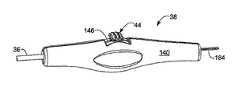
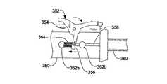
図11のA〜Cおよび図12に見られる制御ハンドル38の例は、いくつかの望ましい他の機能に加えて、制御ロッド112を駆動し顎を開閉するための機構を含む。図11のA乃至Cの正面図および2つの部分断面図に、制御ハンドル38が示されている。制御ハンドル38は、2つの成形された半格納体140a、140bの並置によって形成される外部格納体140を含む。外部格納体140は、それらの間に一連の内部格納キャビティを画定した複数の壁および/あるいは隔壁141を含む。外部格納体に形成された遠位通し孔が、遠位顎40、42に至る可撓性シャフト36を収容する。上述の実施例のアクチュエータ44が、該格納体に対して固定されたピン142に対して旋回するように軸受けされ、ピン142の反対側に親指パッド144を含む。親指パッド144がユーザにスライダーを提供するように、アクチュエータ44の狭い部分が、格納体140における近位−遠位スロット146の内部で移動する。従って、アクチュエータ44は、2つの半格納体140a、140bの間の中空空間において旋回するように制限され、親指パッド144が、スロット146の両端の間を移動する。スライダー144の遠位方向への移動(図11Aにおいて左方向への移動)によって顎が閉じ、スライダー144の近位方向への移動(図11Aにおいて右方向への移動)によって顎が開く。 The example of the control handle 38 seen in FIGS. 11A-C and FIG. 12 includes a mechanism for driving the
例示された制御ハンドル38は、顎を開閉させる機構に加えて、前述の加熱素子を通電するための回路を、該ツールの遠位端に含む。本発明が1つの特定のスイッチ構成に限定されることはないが、本実施例は、溶接加熱素子と切断加熱素子の両方を同時にかつ顎の閉じた位置で起動する溶接/切断スイッチを含む。更に、制御ハンドル38は、その間に組織を保持した2つの顎によって印加されることができる力を制限するための調整器を含む。 The illustrated control handle 38 includes circuitry at the distal end of the tool for energizing the aforementioned heating elements in addition to a mechanism for opening and closing the jaws. Although the present invention is not limited to one particular switch configuration, this embodiment includes a welding / cutting switch that activates both the welding and cutting heating elements simultaneously and in the closed position of the jaws. In addition, the control handle 38 includes an adjuster for limiting the force that can be applied by the two jaws holding the tissue therebetween.
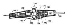
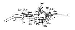
図11のA乃至Cと共に図12の分解組み立て図を参照すれば、アクチュエータ44は、垂直に細長い近位−遠位通し孔152をその内部に有する広がった中央区画150を持つ。通し孔152は近位ヘッド156および遠位ヘッド158を持つロッド154を収容する。ロッド154の近位端は、力伝達ブロック160を通ってアクチュエータ44の近位側のキャビティに伸長する。力伝達ブロック160は、格納体に形成された1対の案内壁の間で近位−遠位方向に力を変換し、ロッド154上を滑ることのできる口径を持つ。力制限バネ164は、ロッドに巻き付けられると共に、近位ヘッド156と遠位ヘッド158との間に拘束される。ロッド154の遠位端は、遠位ヘッド158が力結合器166の中に取り込まれるように、アクチュエータ44の遠位側に伸長する。図12は、おおむね箱形をした力結合器166の内部構成を示す。力結合器166は、大きいキャビティ、遠位ヘッド158が収容される小さいキャビティ、および、その両端部に1対のスロットを含む(参照符号は簡略のため示されていない)。図11のCに見られるように、力結合器166の片方の側面が、連係部品のアセンブリを容易にするため取り除かれている。力伝達ブロック160と同様に、力結合器166は、格納体に形成された1対の案内壁174の間で、近位−遠位方向に力を変換する。 Referring to the exploded view of FIG. 12 along with FIGS. 11A-C, the
図11のBを特に参照すれば、小さい突起部180が、アクチュエータ44の広くなっている中央区画150から横方向に突き出ている。突起部180は、格納体140内に取り付けられた溶接/切断スイッチ182に係合して作動させるように配置される。すなわち、スイッチ182は、格納体140に対して固定されているが、突起部180は、アクチュエータ44と共に旋回する。親指パッド144がスロット146内で近位方向に動くと、アクチュエータ44は、突起部180が溶接/切断スイッチ182のレバーを作動させるまで、時計回りの方向に旋回する。電線184が、ハンドル38の近位端に向かって伸長してスイッチ182に電力を供給する。そこから、導線186が、遠位方向に向かって伸長し、可撓性シャフトを通って該ツールの遠位端における顎上の加熱素子まで伸びる。 With particular reference to FIG. 11B, a
図11のBおよびCは、格納体140の遠位端の隔壁141の間に取り込まれた円筒状フィルタ190を示す。おおむね管状のフィルタ190は、図12の分解図に示されているように、1対のO(オー)リング194をその両端に収容するように、段のついた通し孔192を含む。Oリング194の各々は、可撓性シャフト36の周囲に密着して封止する内側直径を持つ。シャフト36は、格納体140の遠位端に向かって伸長し、フィルタ190を通り、該格納体の隔壁141のうちの1つに隣接したシール(seal)部品196で終わる。図11Cに見られるように、制御ロッド112は、シール部品196を通って続き、力結合器166の中へ進む。力結合器166の大きいキャビティに収容された環状部品(collar)200が、止めねじ202によって制御ロッド112の近位端に締め付けられる。このようにして、制御ロッド112の近位端は、環状部品200によって力結合器166内に拘束される。 B and C of FIG. 11 show the
使用の際には、操作者は、図11Cの矢印204によって示されるようなスロット146に沿った遠位方向に親指パッド144を滑らせると、アクチュエータ44が旋回して該ツールの顎が開く。アクチュエータ44が旋回するにつれて、その角度運動が、ロッド154上の細長い通し孔152によって受け取られる。広くなっている中央区画150の曲がった遠位面が、力結合器166の近位端と最終的に接触して、遠位方向にそれを動かすカムとしての作用を果たす。環状部品200が力結合器166の大きい方のキャビティ内に拘束されているので、環状部品200もまた遠位方向へ力を変換し、その結果、制御ロッド112を遠位方向に押す。本実施形態において、顎を開くためのアクチュエータ44と制御ロッド112の遠位方向運動との間に、クラッチあるいは力制限機構はない。従って、顎が開く範囲は、親指パッド144の移動の範囲あるいは顎自体のちょうつがい構造によって制限される。 In use, when the operator slides the
一方、操作者が図11Bの矢印206によって示されるようなスロット146に沿った近位方向に親指パッド144を滑らせると、アクチュエータ44が旋回して該ツールの顎が閉じる。広くなっている中央区画150の曲がった近位面が、力伝達ブロック160の遠位端と最終的に接触して、それを近位方向に動かすカムとしての作用を果たす。力伝達ブロック160がロッド154上を自由に滑るので、それは近位方向へ移動してバネを圧縮する。力制限バネ164の圧縮が、ロッド154の近位ヘッド156に対し近位方向の力を印加する。遠位ヘッド158が力結合器166の段のついたキャビティ内に拘束され、それが制御ロッド112に連結しているので、ロッド154の近位の変位に対する抵抗が、顎の閉鎖に抵抗する力によって与えられる(最小限摩擦力が制御ロッド112に作用すると仮定する)。顎を組織に固定するに先立ち、ロッド154の近位の変位に対する抵抗が最小となり、力伝達ブロック160の近位変位が、ロッド112の同等の変位に変換される。しかしながら、顎が最終的に組織上で閉じるとき、最大の顎を閉じる力(閉鎖力)は、バネ164の剛性によって制限される。具体的には、顎が閉じた後、一定の力がバネ164によって顎の間の組織に印加される。 On the other hand, when the operator slides the
該ツール上の所定の顎と共に力制限バネ164を注意深く調整することによって、この閉鎖力は、顎内にある組織を不当に破壊あるいは傷つけるような力よりも小さくなるように制限されることができる。当業者に理解されることであろうが、組織へ印加される圧力は制限されなければならないし、該圧力は、バネ164の弾性定数と共に顎の形状および大きさに部分的に依存する。望ましくは、バネ164によって制御され顎によって組織へ与えられる力は、約1ポンドから3ポンド(0.45キログラムから1.36キログラム)の間、好ましくは約1ポンドである。この好ましい力の範囲により、加熱素子が2つの顎の対向する表面内に保持された組織を、適度に短い時間で、好ましくは5秒以内に、効果的に溶接および切断することが保証される。すなわち、1ポンド未満の力を組織に印加すれば切断機能は遅れがちとなり、一方、3ポンドを超える力を印加すれば、効果的な溶接が形成される前に組織が切断される傾向となる。前述のように、この好ましい力の範囲および動作時間は、顎の大きさと形状に依存する。しかしながら、内視鏡組織溶接の制約、とりわけ血管採取術中の制約を考えると、これらのパラメータは、広範囲の適切なタイプの顎に適用可能と考えられる。 By carefully adjusting the
組織溶接器の望ましいパラメータを更に説明するため、熱い顎の内部顎部材62を示す図8のA乃至Hおよび内部顎部材62を覆うブーツ52aを示す図10のA乃至Hを再度参照する。内部顎部材62は、近位の旋回軸格納体66から伸長するカーブした遠位部分64を持ち、丸い旋回軸孔67からその遠位先端部までの長さは約0.740インチ(18.80ミリ)である。上述のように、冷たい顎42の内部顎部材102は、組織の非切開抜去(blunt dissection)を容易にするため、第1の顎40の顎部材62より若干長く、約0.765インチ(19.43ミリ)という長さを持つ。顎部材62は、熱伝導性などを持つ他の材料も利用可能であるが、望ましくは、ステンレス鋼から作られている。遠位部分64の横断面の形状は、旋回軸格納体66に隣接してほぼ正方形であり、各辺が約0.060インチ(1.52ミリ)という寸法を持つ。遠位部分64の組織に対面する側の寸法は、図8Eに見られるように、顎部材62の長さに沿って一定のままであるが、垂直方向の寸法は、図8のDおよびFに見られるように、遠位先端部に向って徐々に細くなり、最終的に約0.031インチ(0.79ミリ)となる。ブーツ52aは、図10のA乃至Hに見られるように、カーブした遠位部分64を覆うのに十分な全長を持ち、約0.082インチ(2.083ミリ)という組織に対面する横幅を持つ。冷たい顎のブーツ52bの寸法パラメータは同等であるが、2つのブーツは異なる機能を実行するので異なるよう構成される。 To further illustrate the desired parameters of the tissue welder, reference is again made to FIGS. 8A-8H showing the hot jaw
1乃至3ポンドの間の望ましい顎を締め付ける力は、切断と溶接の間で最も効果的なバランスを生みだす組織に対する圧力という観点から特徴づけられることができる。上述のように与えられたおおよその寸法値を使用して、顎は、望ましくは、約25-75psiという圧力を組織に及ぼす。この圧力値は、ブーツ52a、52bの組織に対面する表面にわたる平均値である。理解されるべき点であるが、この範囲は、ブーツ52a、52bの組織に対面する表面の不均一な輪郭に基づいて推定されている。また、当業者に理解されることであろうが、顎に対する構造的な変更が、好ましい力および/あるいは圧力の範囲に影響を与えることがある。更に、顎の加熱素子によって上昇する温度も、溶接の持続時間と共に、好ましい印加される力に影響する。繰り返すが、人体組織が溶接される温度として一般に許容可能な温度範囲は50乃至90℃であり、切断は100℃で起きる。このようなガイドラインを使用することによって、本実施例の顎が組織に対して1乃至3ポンドの間の締め付け力を適用し、溶接および切断加熱素子が上記のような温度となるよう通電されるとすれば、好ましい溶接持続時間は1乃至5秒の間である。もし締め付け時間が短すぎると、溶接は効果を発揮せず、組織を完全に切断しないこともある。一方、5秒以上の過剰な時間は、組織を焦がすおそれがある。 A desired jaw clamping force of between 1 and 3 pounds can be characterized in terms of pressure on the tissue that creates the most effective balance between cutting and welding. Using the approximate dimension values given as described above, the jaw desirably exerts a pressure on the tissue of about 25-75 psi. This pressure value is an average value over the surface facing the tissue of the
図11のBをなおも参照すれば、矢印206の方向におけるアクチュエータ44の動きが、突起部分180を変位させて、溶接/切断スイッチ182に係合させる。たとえ介入する力制限バネ164が顎の更なる閉鎖を制限するとしても、スイッチ182が作動するまでアクチュエータ44は移動を続けることができる。本発明の制御ハンドル38は、スイッチ182がオンおよびオフに作動された時を、聴覚的に、および親指パッド144を介した触感的にユーザに知らせるフィードバック機能を含む。具体的には、図11のCおよび図12に示されているような、アクチュエータ44から横方向に突き出た小さい突出部208が、アクチュエータと共に旋回し、旋回するもどり止め212(図12参照)に設けられた小さい歯210に係合する。図11のCに図示されてないが、もどり止め212は、格納体140内に固定された或る点の周囲を旋回し、歯210は、戻りばね214によって上方に付勢されている。スイッチ182がオンとなった時点で、突出部208は、歯210に係合し(cam past)、音声および触覚のクリック(click,カチッという音)でユーザに知らせる。また、アクチュエータ44の反対方向への動きによって、突出部208は、歯210に係合し、スイッチがオフに切り替わったことを示す。1つの実施例において、溶接時間は、典型的には5秒未満である。 Still referring to FIG. 11B, movement of the
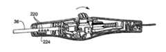
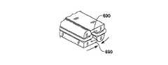
図11のA乃至Cおよび図12に例示されている制御ハンドル38は、組織の腔(cavity)内の手術位置に、遠位の顎によって生成されるスモーク(smoke)または微粒子(particulate matter)を捕捉するためのシステムを更に含む。上述のように、実施例として記述された抵抗加熱素子を含む種々の端部部品が本発明の所定の側面で利用されることができる。抵抗加熱素子を含むこれら端部部品の大部分は、加熱された組織から相当量のスモーク発生させる原因となることが多い。更に、手術は、典型的には、可撓性シャフト36を通って近位方向において圧力勾配(pressure gradient)を起こすガスを生成するCO2吹送(insufflation)を使用して実行される。The control handle 38 illustrated in FIGS. 11A-C and FIG. 12 allows the smoke or particulate matter generated by the distal jaw to be placed in a surgical position within the tissue cavity. It further includes a system for capturing. As described above, various end pieces including resistance heating elements described as examples can be utilized in certain aspects of the present invention. Most of these end pieces, including resistance heating elements, often cause a significant amount of smoke from the heated tissue. In addition, surgery is typically performed using a CO2 insufflation that produces a gas that causes a pressure gradient in the proximal direction through the
可撓性シャフト36を通るこのようなガスの放出を制御するため、制御ハンドル38は、前述の受動(passive)フィルタ190を提供する。可撓性シャフト36は、その近位端に少なくとも1つのガス流出ポート220を含む。このポート220は、1対のOリング194の間でフィルタ190の中空内部に配置される。フィルタ190の該中空キャビティは、ポート220からガスを受け取る排気チャンバすなわち空間を提供する。加えて、可撓性シャフト36の近位端は、制御ロッド112および導線186の周りに沿った封止部品196によって蓋をされる。このような封止部品によって、可撓性シャフト36を近位方向に通るいかなるガス(スモークまたは微粒子)も、ガス流出ポート220から出るように強制される。従って、ガスは、いかなるスモークや微粒子をも格納体140の内部に達する前に捕捉するフィルタ190のガス透過材料を通るように強制される。こうしてフィルタリングされたガス(主としてCO2)は、格納体140内の種々のキャビティを通過して、それらのランダムな割れ目および開口部から外へ出る。In order to control the release of such gas through the
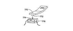
組織溶接術によって生成されるスモークをフィルタリングするためのいくつかの代替構成が、図11のD乃至Fに示されている。先ず、図11のDは、近位端に取り付けられた煙排出ファン222を有する制御ハンドル38の例を示す。排出ファン222は、前述の受動フィルタ190を介して細長いシャフト36を通るガスを引き出す助けをする。多くの場合、ガス吹送(gas insufflation)の手段が、組織溶接器が使用されるシステム全体に対して提供されるものであり、これは、体腔内に正圧を与えると共に、ガスを、細長いシャフト36を介して近位方向に行かせる。しかしながら、場合によっては、吹送は使用されないし、十分な圧力も生成されない。そのような場合、補助ファン222が、ガスをフィルタに通すのを助ける。 Several alternative configurations for filtering smoke produced by tissue welding are shown in FIGS. 11D-F. First, FIG. 11D shows an example of a
図11のEは代替制御ハンドルを示す。該ハンドルには、ペルチェ(Peltier)冷却器のような冷却装置224が、細長いシャフト36のガス流出ポート220に隣接して取り付けられている。ポート220から排出されたスモークは、冷却装置224で効果的かつ受動的にフィルタリングされ、フィルタリングされたスモークが、ハンドル内の種々の開口部から外へ出る。 FIG. 11E shows an alternative control handle. Mounted on the handle is a
更なる代替制御ハンドルが図11のFに示されている。このハンドルには、複数のルーバー(louver)すなわちフィン226が、ガス流出ポート220に隣接して配置されている。フィン226は、細長いシャフト36を近位方向に進むスモークを拡散および凝縮(condense)することによって受動フィルタの機能を果たす。ガスは、ハンドル内の種々の開口部から外へ出る。スモークが通って排出する表面領域が広げられるので、スモークの濃度が低減して、ハンドルを出る際に煙が目立たなくなる。本実施例において、フィン226は、一連の同心の環状構成要素として配置されているが、他の構成も可能である。 A further alternative control handle is shown in FIG. The handle has a plurality of louvers or
図13A乃至Cには、上記と同様の代替制御ハンドル38'が示されているが、このハンドルは、遠位ツール上に設けられる筋膜切開カッターのための別個の電気回路を含む。上述のように、筋膜切開術は、筋膜(例えば、組織の異なった層を切り離す線維組織の帯すなわちフィレ)の切開を含む。組織溶接/切断顎は、顎を開閉することなく組織を切断するように、該ツールが直線的に移動することを可能にするような筋膜切開用カッターを含むように構成されることもできる。筋膜切開用カッターは、顎のうちの1つの前方端部上にあるいは顎の内部に設けられる別個の加熱素子であってもよい。代替制御ハンドル38'に関して図示される構成要素のいくつかは、図11および図12を参照して上述された制御ハンドル30と共通であり、同じ参照番号が与えられている。 13A-C show an alternative control handle 38 'similar to that described above, but this handle includes a separate electrical circuit for the fasciotomy cutter provided on the distal tool. As noted above, fasciotomy involves the incision of fascia (eg, a band or fillet of fibrous tissue that separates different layers of tissue). The tissue welding / cutting jaw can also be configured to include a fasciotomy cutter that allows the tool to move linearly to cut tissue without opening and closing the jaw. . The fasciotomy cutter may be a separate heating element provided on the front end of one of the jaws or inside the jaw. Some of the components illustrated with respect to the alternative control handle 38 'are common to the control handle 30 described above with reference to FIGS. 11 and 12, and are given the same reference numerals.
図13のBおよびCを参照すれば、遠位ツールからの可撓性シャフト36'は、成形された格納体140'に入り、制御ロッド112'が、そこから、該格納体内に形成されたキャビティに突き出て、広くなっている環状部品230に固定されている。図示されていないが、環状部品230に締め付けられたシャフト部材232が、筋膜切開バネ234を通って近位方向に伸長し、アクチュエータ44'を通って近位ヘッド236まで伸びている。アクチュエータ44'は、上述のアクチュエータ44とほとんど同じであるが、ピン238の周りを旋回するボディーを含み、シャフト232を通すための細長い通し孔を有する。環状部品230をその上に持つシャフト232の遠位端が、近位−遠位キャビティ240内を移動するが、一方、近位ヘッド236を持つシャフトの近位端は、近位−遠位キャビティ242内を移動する。制御ロッド112'が、環状部品230に固く締め付けられ、該環状部品230がシャフト232に締め付けられているので、シャフトの運動は、制御ロッドと同じ運動を生む。 Referring to FIGS. 13B and 13C, the flexible shaft 36 'from the distal tool enters the molded enclosure 140' from which the control rod 112 'has been formed within the enclosure. It protrudes into the cavity and is secured to the wide
図13のCを特に参照すれば、環状カムフォロア244が、アクチュエータ44'と筋膜切開用バネ234との間でシャフト232を取り囲んでいる。カムフォロア244は、短いスロット(参照番号は付けられてない)を含み、このスロットの内部には、シャフト232から横方向に突き出た小さいピン246が伸長している。図示される位置において、アクチュエータ44'は、カムフォロア244に接触していない中立位置にあり、従って、カムフォロア244は、ピン246およびスロットが許容する限り、筋膜切開バネ234によって近位方向に付勢されている。第2のカムフォロア250が、アクチュエータ44'と筋膜切開用バネ234との間でシャフト232を取り囲む。力制限バネ252が、近位ヘッド236と第2のカムフォロア250との間でシャフト232の周りで同軸に拘束されている。前述のように、アクチュエータ44'は、第2のカムフォロア250に接触していない中立位置にあり、従って、力制限バネ252は圧縮されていないままである。 With particular reference to FIG. 13C, an
ユーザが、図13Bの矢印260によって示されるように、遠位方向にアクチュエータ44'の親指パッドの位置を変えると、アクチュエータ44'が旋回し、カムフォロア244が近位方向に動く。筋膜切開バネ234の圧縮によって、環状部品230および制御ロッド112'が比例して変位し、これにより、該ツールの顎が開く。所定の移動距離で、環状部品230がキャビティ240の端部に到達し、顎の最大開口距離に対応して、制御ロッド112'の更なる動きが妨げられる。しかしながら、カムフォロア244が、その中でピン246が移動する線形スロットを含むので、アクチュエータ44'は、バネの圧縮力に抗してカムフォロア244を近位方向に移動させる動きを継続することができる。ユーザはこの段階で、アクチュエータ44'の運動に対する抵抗を感じる。これは、筋膜切開用加熱素子が作動したことの標示である。特に、アクチュエータ44'の突起部262(図13C)が、筋膜切開バネ234が圧縮されている時点で筋膜切開スイッチ264に最終的に係合する。回路は図示されていないが、スイッチ264に電流が供給され、該スイッチがオンとなると、可撓性シャフト36'を通って該ツールの遠位端および筋膜切開加熱素子に伸びる導線に電流が供給される。 When the user changes the position of the thumb pad of actuator 44 'in the distal direction, as indicated by
一方、ユーザが図13Cの矢印270によって示されるように、近位方向にアクチュエータ44'の位置を変えると、顎が閉じる。アクチュエータ44'の近位表面がフォロア250に係合して力制限バネ252に対抗するようにはたらく。前述の実施形態の場合と同様に、顎が閉じるに先立ち最小限の反力が存在するので、アクチュエータ44'の動きが制御ロッド112'の比例的動きをもたらすことになる。顎が組織上で閉じる時点で、アクチュエータの44'の更なる運動が制御ロッド112'を動かさず単にバネを圧縮することとなる前に、力制限バネ252が、組織へ印加される圧力量を決定する。矢印270の方向におけるアクチュエータ44'の動きの限界の近くで、突起部262が、格納体140'内に取り付けられた溶接/切断スイッチ272に係合し、これにより、該ツールの遠位端にある溶接および切断加熱素子が作動される。代替の制御ハンドル38'は、更に、前述の戻り止め212と同じはたらきをし、溶接/切断機能のオンおよびオフをユーザに示す戻り止め274を含む。 On the other hand, when the user changes the position of the actuator 44 ′ in the proximal direction, as indicated by the
図14のA乃至Cには、顎の開閉を行うための、制御ロッドと顎の間の好ましい連結部300が示されている。従来の顎開き機構においては、例えば、顎アセンブリのサイズ全体の増加、製作コストの増加、露出した電気接続部の摩耗、過剰な摩擦源を含むことによる機械的、電気的整合性の犠牲、または、電気的の連続性のための機械的接続部の移動に依存することによる電気的整合性の犠牲などの欠点が認識された。例示される連結部300および関連する"ハードワイヤード(hard-wired)"な電気接続が、顎アセンブリのサイズ全体を減少し、コンポーネントの数、関連するコスト、および複雑度を減少し、機械のロバスト性を向上させ、装置の機械的および電気的な信頼性(すなわち整合性)を向上させる。 FIGS. 14A-C show a
1対の顎302、304が、図14のAおよびBに示されている。顎の各々は、図5のBに見られるシャフトスタブ98のような、シャフト306に軸受けされる通し孔を含む。このようにして、それぞれの顎の近位格納体308、310が、互いに旋回する。角度のついたスロット312、314が、それぞれの旋回軸格納体308、310に設けられる。作動ピン316が、角度のついたスロット312、314の両方に伸長し、近位制御ロッド(図示されてない)に接続されている。図14のBは、旋回軸格納体308、310を囲むツール・シャフト320の遠位端を示す。ツール・シャフト320は、作動ピン316がその中を移動する線形スロット322を含む。図示されているツール・シャフト320の遠位端は、図2および図4に見られるシャフト先端部54に類似している。 A pair of
図14のCは、顎の302、304を閉じさせる作動ピン316の左方向への動きを示す。すなわち、それぞれのスロットの近位端が図のように一緒になるように、ピン316が角度のついたスロット312、314に係合する。当然のことながら、作動ピン316の反対方向への動きによって、顎は再び開く。単純な機構のため、顎アセンブリのサイズ全体は、内径5mmの管に収まるように減少させることができる。更に、部品の数の減少が、対応する製造時間および複雑度の減少、一層低い製造コストとなる。可動部品は、3つのスロット内を移動する作動ピン316および相互に旋回する2つの顎から成る。これによって、摩擦の源(ソース)が減少し、その結果、機械的信頼性が向上する。最後に、スロット312、314の角度は、顎の開閉に必要とされる作動力を変えるように調整することができる。すなわち、比較的浅い角度にすれば、顎を作動させるための制御ロッドからの力が比較的小さくて済むことになる。当然のことながら、トレードオフとして、2つの顎の開き距離を同時に減少する。 FIG. 14C illustrates the leftward movement of the
明らかに、2重あるいは3重の加熱素子機能は、多くの異なった形態で達成することができる。本発明は、組織を切断するための加熱素子および組織を溶接するための加熱素子を幅広く含み、いずれかの装置の特定のタイプに限定されない。いくつかの例には、2つ、3つあるいはそれ以上の加熱素子、切断および溶接加熱素子が含まれるが、それらに限定されることはない。そのような加熱素子は、1つまたは両方の顎上で別々に作動されることも、並列または直列に接続することもできる。複数の加熱素子の形態は、好ましくは、それらが相互に比較的接近し、一方が種々の組織を高い信頼度で切断し、他方が高い信頼度で組織を溶接するように、選択される。オプションとして、複数の加熱素子が、実質的に同時に作動し、溶接される組織の良好な止血作用を保証するように、構成される。不意に組織を焦がしたりあるいは他のそのような損傷が装置の正規な操作中に意図せずに生じないことを保証するように、印加される電力および加熱素子の形状が選択される。本発明の加熱素子の治療についての主要な利点には、首尾一貫した強い溶接のため切断器および溶接器からの均衡した力の出力および一層速い溶接時間のための熱効率が含まれるが、それらに限定されることはない。 Obviously, the double or triple heating element function can be achieved in many different forms. The present invention broadly includes a heating element for cutting tissue and a heating element for welding tissue, and is not limited to any particular type of device. Some examples include, but are not limited to, two, three or more heating elements, cutting and welding heating elements. Such heating elements can be actuated separately on one or both jaws or connected in parallel or in series. The form of the plurality of heating elements is preferably selected such that they are relatively close to each other, one cutting the various tissues with high reliability and the other welding the tissue with high reliability. Optionally, the plurality of heating elements are configured to operate substantially simultaneously and ensure good hemostasis of the tissue to be welded. The applied power and the shape of the heating element are selected to ensure that no tissue is accidentally scorched or other such damage occurs unintentionally during normal operation of the device. Major advantages for treatment of the heating element of the present invention include balanced force output from the cutter and welder for consistent strong welding and thermal efficiency for faster welding times, including There is no limit.
理解されるべき点であるが、制御ハンドル内のバネの力制限機能は、多くの形態で達成することができる。本発明は、その広範囲の解釈において、いかなる1つのタイプの顎閉鎖機構にも特に限定されることはないが、顎の閉鎖力の大きさを制限するための、制御アクチュエータと細長い顎との間の力制限インタフェースによって特徴づけられる。いくつかの例には、制御ハンドル内に設けられた前述のバネ、制御ハンドルに対して遠位に設けられる同様のバネ、顎によって印加される力を制限するためユーザまたは他の装置にフィードバックを提供するように顎上に設けられる圧力変換器、および、順応型の(compliant)顎等々が含まれるが、それらに限定されることはない。力制限装置の形態は、好ましくは、所定の顎によって組織に印加される圧力を制限するように選択される。オプションとして、力制限装置は、単にコスト対費用効果の観点から構成される。力制限装置は、装置全体の正常な操作中に組織が押しつぶされるということが意図せずに生ずることのないよう、選択される。 It should be understood that the force limiting function of the spring in the control handle can be achieved in many forms. The present invention, in its broad interpretation, is not particularly limited to any one type of jaw closure mechanism, but between a control actuator and an elongated jaw to limit the magnitude of the jaw closure force. Characterized by a force-limiting interface. Some examples include the aforementioned springs provided in the control handle, similar springs provided distal to the control handle, and feedback to the user or other device to limit the force applied by the jaws. These include, but are not limited to, pressure transducers provided on the jaws as provided, compliant jaws, and the like. The form of the force limiting device is preferably selected to limit the pressure applied to the tissue by a given jaw. Optionally, the force limiting device is simply configured from a cost-effective perspective. The force limiting device is selected so that it does not unintentionally cause tissue to be crushed during normal operation of the entire device.
更にまた、顎によって印加される力の大きさを制限することに加えて、本発明の実施形態は、顎内の組織にかかる力について、該力が、最小量より大きいが組織を不当に損傷するような力より小さくなるよう、意図されている。力の最小量は、組織を締めつけて加熱することによって効きめのある溶接が生じるように決定される。従って、必要とされる力の最小量は、印加される熱の量および持続時間、顎の大きさと形状、顎およびブーツの材料、顎内の組織あるいは血管の大きさおよび特徴などを含むいくつかの要因に依存する。1つの好ましい実施形態において、制御アクチュエータと顎の間に挿入される力制限機構は、2つの細長い顎の対向する表面内に保持される組織を加熱素子が効果的に溶接することを保証するよう調整された値に顎を閉じる力の大きさを制御するように構成される。 Furthermore, in addition to limiting the magnitude of the force applied by the jaw, embodiments of the present invention provide for the force on tissue within the jaw that is unduly damaged by the force being greater than a minimum amount. It is intended to be less than the force to do. The minimum amount of force is determined so that effective welding occurs by tightening and heating the tissue. Thus, the minimum amount of force required is several, including the amount and duration of heat applied, jaw size and shape, jaw and boot materials, tissue or blood vessel size and characteristics within the jaw, etc. Depends on the factors. In one preferred embodiment, a force limiting mechanism inserted between the control actuator and the jaws ensures that the heating element effectively welds the tissue held in the opposing surfaces of the two elongate jaws. It is configured to control the magnitude of the force to close the jaw to the adjusted value.
上述の組織溶接システムが特に効果的であると信じられるが、本発明は、また、各々がそれ自体の発明上の権利を持つと信じられるいくつかの代替的な顎および締め付け機構を提供する。図15乃至図48を参照して、それらいくつかの代替実施例を以下に簡単に記述する。例えば、本実施形態は、顎内の組織に印加される局所的な力を調整するいくつかの実施例を提供する。いくつかの実施例は、顎の平行性を維持するようにはたらき、これは、印加される力、従って印加される熱を、顎の近位端から遠位端まで均一にさせるのに役立つ。別の構成では、顎がハンドル・アクチュエータの運動に対して非線形に動くように、互いの顎の総体的な運動を制御する。つまり、本実施形態は、印加される力および遠位の組織溶接顎の変位を制御するための数々の構成を提供する。理解されるべき点であるが、相互に排他的でない限り、これらの顎および締め付け構成のいずれも前述の制御ハンドル/シャフトの実施例のいずれとでも結合させることができる。例えば、所定の顎が可鍛性のある組織接触表面を含む場合、そのような顎もまた、圧力制限バネを含む図11および図12の制御ハンドル38と共に使用することができる。 While the tissue welding system described above is believed to be particularly effective, the present invention also provides several alternative jaw and clamping mechanisms that are each believed to have their own inventive rights. Some alternative embodiments of these are briefly described below with reference to FIGS. For example, this embodiment provides several examples of adjusting the local force applied to tissue in the jaw. Some embodiments serve to maintain jaw parallelism, which helps to make the applied force, and thus the applied heat, uniform from the proximal end to the distal end of the jaw. In another configuration, the overall movement of each jaw is controlled so that the jaws move non-linearly with respect to the movement of the handle actuator. That is, this embodiment provides a number of configurations for controlling the applied force and the displacement of the distal tissue welding jaw. It should be understood that any of these jaw and clamping configurations can be combined with any of the previously described control handle / shaft embodiments, unless they are mutually exclusive. For example, if a given jaw includes a malleable tissue contacting surface, such a jaw can also be used with the control handle 38 of FIGS. 11 and 12 including a pressure limiting spring.
ここで図15のAおよびBを参照すれば、制御ハンドル350の内部の力制限構造の第1の実施形態が示されている。ここには制御ハンドル350の一部だけが図示されており、制御ハンドルの残部は図11乃至図13を参照して記述されたものと同じである。制御ハンドル350は、ピン354の周りを旋回する1つのアクチュエータ352を含む。アクチュエータ352からハンドル350に突き出たレバー・アーム356が、制御ロッド358に係合する。制御ロッド358が、可撓性シャフト360を通って遠位方向に延伸して、上述のように、遠位の組織溶接顎(図示されていない)を開閉する。レバー・アーム356は、例えば、その端部が近位ボール362aと遠位ボール362bとの間で制御ロッド358にまたがるように、分岐される。バネ364が、制御ロッド358を同心状に取り囲み、レバー・アーム356と近位ボール362aとの間に挿入される。 Referring now to FIGS. 15A and 15B, a first embodiment of a force limiting structure inside the control handle 350 is shown. Only a portion of the control handle 350 is shown here, and the remainder of the control handle is the same as described with reference to FIGS. The control handle 350 includes a
アクチュエータ352が、図15Aに見られるように、時計回りの方向に回転させられると、レバー・アーム356が、バネ364に対して左方向に動き、その結果、近位ボール362aに抗する動きとなる。顎の反力(reaction force)がバネ定数より小さい限り、バネ364は、圧縮されない状態を保ち、剛体(rigid body)として動く。制御ロッド358のこの方向の動きは、遠位にある顎の閉鎖に対応する。顎が組織上で閉じるかあるいは更なる閉鎖を妨げられると、制御ロッド358を通る反力が最終的にバネ定数より大きくなり、レバー・アーム356が近位ボール362aに対してバネ364を圧縮する。レバー・アーム356は移動を続けるが、制御ロッド358の運動を変換することはなく、組織を締め付ける顎の力は一定のままである。反対に、アクチュエータ352の逆時計回り回転は、図15Bに見られるように、レバー・アーム356を右方向へ移動させて、遠位ボール362bに直接作用することになる。遠位ボール362bが制御ロッド358に固く取り付けられているので、アクチュエータ352の旋回運動は、制御ロッドの線形変位に直接変換され、そのために顎が開く。この配置は図11乃至図13を参照して上述した力制限構成に類似している。 When the
図15のAおよびBの実施形態に対する若干のバリエーションとして、レバー・アーム356を、コイル・バネ364の代わりにバネとして形成することもできる。そのような代替構成においては、レバー・アーム356は、制御ロッド358の周りに分岐される金属または成形されたプラスチックの板ばねである。閉鎖力の印加により、レバー・アーム356が曲がり、それによって、顎において印加される締め付け力が制限される。レバー・アーム356が所定の力で確実に曲がることを保証するために、控え目な負荷に達するまで一層長く締め付けに抵抗することを可能にする付加的な構造的剛性のための凹部(管楽器のためのリード(reed)に類似している)を用いてレバー・アーム356を形成することもできる。 As a slight variation on the embodiment of FIGS. 15A and 15B, the
図16のAおよびBは、力制限構成の1つの代替バリエーションを示す。アクチュエータ370は、親指レバー372およびレバー・アーム374によって画定される剛性部分を含み、この部分がピン376を旋回する。第2の親指レバー378が、同じくピン376の周りを旋回し、コイル・バネ380を介してレバー・アーム374に接続される。図示されていないが、遠位の組織溶接顎を開閉するために接続される制御ロッドは、レバー・アーム374の遠位端と共に動くように結合されている。図16のAに示されているように、親指レバー372を逆時計回り方向に押すことによって、レバー・アーム374が右へ移動し、遠位顎を開く制御ロッドの線形運動に対応する。一方、図16Bに示されているように、第2の親指レバー378を時計回り方向に押すことによって、レバー・アーム374および制御ロッドが左へ移動し、遠位顎が閉じる。最終的に、制御ロッドからレバー・アームに伝達される顎からの反力が、コイル・バネ380を圧縮させるのに十分なものとなり、それによって、第2の親指レバー378の運動が遠位顎の運動から効果的に切り離される。この場合もまた、バネ380が圧縮し始めた後、組織に対する締め付け力は一定のままとなる。 16A and 16B show one alternative variation of the force limiting configuration.
図17のAおよびBは、拡張部392およびレバー・アーム394によって画定される剛性部分を持つ代替的な力制限アクチュエータ390を示す。剛性部分は、ピン396の周囲を旋回するが、相反する側に伸長する2つの翼部を持つ親指レバー398も、ピン396の周りを旋回する。図17Aに示されるように親指レバー398の翼部のうちの1つを逆時計回り方向に押すことによって、拡張部392が動き、その結果、レバー・アーム394が右へ移動して制御ロッド(図示されてない)を線形に動かし、次に、制御ロッドが遠位の組織溶接顎を開ける。図17Bに示されているように、反対の翼部を時計回り方向に押すと、板ばね400がレバー・アーム394の片側に接触する。レバー・アーム394が左に移動するにつれて、制御ロッドを引っ張り、その結果、顎が閉じる。最終的には、組織に対する顎の閉鎖によって、反力が制御ロッドを通して伝達され、レバー・アーム394の更なる運動が制約される。ユーザが親指レバー398の翼を更に押したとしても、板ばね400が単に曲がるに過ぎない。 17A and B show an alternative
特に例示されてない制御ハンドル内に提供される代替的な力制限構造は、互いに反発する1対の磁石を含む。例えば、図17のAおよびBにおいて、レバー・アーム394および親指レバー398が、相互に対向する同様の磁極を持つ磁石を備え、親指レバー398が時計回り方向に軸旋回する時、該対向する磁石が更なる閉鎖運動に対する抵抗を生成するようにする。 An alternative force limiting structure provided in a control handle not specifically illustrated includes a pair of magnets that repel each other. For example, in FIGS. 17A and B, the
図18には、制御ハンドルに取り付けられた力制限構造のもう1つのバリエーションが示されている。アクチュエータが、レバー・アーム410および垂直の拡張部412を持つ剛性部分を含む。該剛性部分は、シャフト414の周囲を旋回し、該シャフト414を軸として、対向する2つの翼を持つ親指レバー416が旋回する。ピンあるいは他のそのような突出部材418が、拡張部412に係合するように、親指レバー416の右側の翼から垂直に伸びる。右側の翼の遠位端および拡張部412が、コイル・バネ420によって接続される。親指レバー416の右側の翼を押すと、ピン418が、拡張部412に接触し、拡張部412をシャフト414の周囲に対して旋回させる。これによって、レバー・アーム410に接続した制御ロッド422が動く。親指レバー416の左側の翼を押すと、制御ロッド422およびレバー・アーム410を通る反力によってコイル・バネ420が伸びる時間まで、拡張部412がシャフト414の周囲を時計回りの方向に回転する。FIG. 18 shows another variation of the force limiting structure attached to the control handle. The actuator includes a rigid portion having a
親指レバーと制御ロッドとの間にバネを配置する代わりに、両者の間の相対的運動を完全に切り離すクラッチを設けることもできる。例えば、図19は、図18と同様な構成を示しているが、コイル・バネ420の代わりに、アクチュエータの剛性部分上にボールもどり止め430が設けられている。親指レバー416が逆時計回り方向に旋回すると、もどり止め430は、左側翼部に係合する。反力が或るしきい値に達すると、親指レバー416がそれ以上制御ハンドルに作用しないように、ボールもどり止め430がスリップ(空回り)する。 Instead of placing a spring between the thumb lever and the control rod, a clutch can be provided that completely decouples the relative movement between the two. For example, FIG. 19 shows a configuration similar to that of FIG. 18 except that a
クラッチ構成の別のバリエーションが図20に示されている。この構成においては、(フレーム443によって表されている)制御ハンドル内にある制御ロッド442の近位端上に歯形ラック440が取り付けられる。アクチュエータ444は、歯形ラック440に係合するバネ装填(spring loaded)ピン446を含む。アクチュエータ444が左または右に動くと、歯形ラック440および制御ロッド442が同様に動く。遠位顎内の組織が制御ロッドの動きを停止させる場合、最終的に、ピン446は、そのバネに抗して上方に移動して、ラック440の歯から外れる。1方向に戻り力を与えるため、フレーム443とアクチュエータ444との間に第2のバネ448を取り付けてもよい。 Another variation of the clutch configuration is shown in FIG. In this configuration, a
図21は、力制限部材として使用するためのバネの代替構成を示す。この実施形態において、管状制御ロッド450が、バネそれ自体を備える。すなわち、制御ロッド450におけるレーザ・カットの螺旋452が、制御ロッドに印加されている所定の力に対して圧縮または伸長するように設計された螺旋形部分(helical section)を形成する。従って、この構成は、制御ロッドの周囲に設ける別個のコイル・バネが不要となる。制御ロッド450内のバネを形成する更なる代替構成において、制御ロッドの一部あるいは全体が、しきい値の張力の印加の後に相転移が起こって伸長するニチノール(Nitinol)のような超弾性材料から作製されることができる。望ましくは、後者の構成において、顎を閉じる時に印加されることができる力を制限する超弾性の引っ張りロッド(pull rod)と共に、別個の剛性の押しロッド(push rod)が顎を開けるため設けられることができる。1つの特定の実施形態において、30cm長の超弾性引っ張りロッドが、その弾性限界(Nitinolの場合通常6%)を超えることなしに約5%の伸長(1.5センチ)を耐えるので、閉じた顎に更なる力を印加することなくアクチュエータの更なる移動を可能にする。この場合においても、弾性のある力制限部材によって、顎が閉じた後は2つの顎の間の組織に一定の力が印加される。 FIG. 21 shows an alternative configuration of a spring for use as a force limiting member. In this embodiment, the
図22のAは、本発明の組織溶接器のための代替的な力制限構成を示す。この力制御構成は、ハンドル460内に配置されていない。アクチュエータ462は、アアクチュエータ・ロッド466に固定された2つのボールに対して相反する方向で作用するレバー・アーム464を含む。アクチュエータ・ロッドは、可撓性シャフト468内へ伸長し、その遠位ブロック470に固定して取り付けられている。小さいフランジ472も、アクチュエータ・ロッド466に設けられている。近位ブロック474が、アクチュエータ・ロッド466を収容する通し孔を含む。制御ロッド476が、近位ブロック474に固定して取り付けられていて、遠位方向に遠位ブロック470の通し孔に伸びている。コイル・バネ478が、遠位および近位ブロック470、474の間の領域においてアクチュエータ・ロッド466と制御ロッド476の両方を囲む。 FIG. 22A shows an alternative force limiting configuration for the tissue welder of the present invention. This force control arrangement is not located within the
図示されているようなアクチュエータ462の時計回り方向の回転によって、レバー・アーム464が近位ボールに作用して、アクチュエータ・ロッド466を左へ動かす。この動きが、図示されているように、遠位ブロック470を左へ引き、また、バネ478によって近位ブロック474および制御ロッド476が左方向へ動く。典型的には、このような動きは、遠位の組織溶接顎の閉鎖に対応する。ある時点で、顎が閉じ、すなわち顎が組織に対して閉じ、制御ロッド476の更なる左方向への運動を制約する。アクチュエータ・ロッド466の更なる運動は、バネ478を単に圧縮するに過ぎない。これは、図22Aに示されている状態であり、フランジ472と近位ブロック474の間に空間Sが存在する。反対方向へのアクチュエータ462の回転が、アクチュエータ・ロッド466の遠位ボールに作用して、その結果、遠位ボールが右の遠位方向へ動く。この場合、フランジ472が、近位ブロック474に直接作用し、制御ロッド476を右へ同等の距離押す(これは図22のBの代替構成に関して示されている)。 The clockwise rotation of the
図22のBは、図22のAの力制限構成を若干変更した実施形態であり、第1のコイル・バネ478のみならず第2のコイル・バネ480も組み込まれている。2つのバネ478、480は、遠位顎の閉鎖に対する制御が2段階で起きるように、2つの異なったバネレート(spring rate, バネ定数)を提供する。すなわち、遠位顎が第1の反力を与える時、第1のバネ478が圧縮する。ユーザは、この抵抗を感じて、組織が顎の間に挟まれたことを知る。バネ478の更なる圧縮によって、究極的には、より高いバネ定数を持つ第2のバネ480が圧縮する。第2のバネ480は、スイッチの作動を区別するために使われることができる。例えば、溶接あるいは筋膜切開の区別のため、または、把持と溶接とを区別するもどり止めとして使用することができる。 FIG. 22B shows an embodiment in which the force limiting configuration of FIG. 22A is slightly changed, and not only the
ここで、図23を参照すると、1対の組織溶接顎500が、制御ロッド502の端部に取り付けられている。制御ロッドの一部分が、磁石506によって囲まれたボイス・コイル(voice coil)504を持つ。このアセンブリは、ボイス・コイル504への通電に応じて制御ロッド502を近位および遠位方向に移動させるための電動アクチュエータ508を提供する。この実施例において、戻りバネ510が、固定点517によって表される制御ハンドルに制御ロッド502を接続する。電動アクチュエータ508の強度は、望ましくは、顎500内の組織を溶接すために必要とされる最小限よりも強くかつ組織を不当に損傷するような力よりも弱くなるように調整される。電動アクチュエータ508の強度は、コイル504あるいは磁石506の選択によって、または、コイルに供給される電流を制御することによって、制御することができる。ソレノイドあるいはボイス・コイルいずれでも望ましい応答を提供するので、電動アクチュエータ508はどちらで構成してもよい。 Referring now to FIG. 23, a pair of
図24は、組織溶接顎524のうちの一方の顎の柔らかい(soft)材料522内に提供される力制限板バネ520を示す。加熱素子526は、反対側の顎上に示されている。2つの顎の間の組織に対して顎が閉じると、板バネ520が最終的に曲がり、それにより、組織に印加される力の量が制限される。 FIG. 24 shows a force limiting
図25に示される構成は、図24と同様であるが、加熱素子532を含む顎のうちの1つ内に、一連のバイメタリック(bimetallic)挿入部品530が配置されている。バイメタリック挿入部品530は、U字形をしていて、その2つの材料は、加熱とともにその異なる膨張率によって挿入部品がまっすぐに伸びるよう選択される。顎は、最大限に閉じても間隙534が存在するように、構成される。加熱素子532が作動すると、バイメタリック挿入部品530はそのU字形構成からまっすぐ延び、そのため、加熱素子532が間隙534内の組織に押しつけられる。バイメタリック挿入部品530の二重の材料および/あるいは加熱素子532によって供給される熱量の注意深い制御が、組織の損傷を伴うことなく適切な溶接が起こることを保証する。一般的には、顎の両方または1つに提供される弾性部材は、上昇した温度において形状を変更するように構成される。例えば、バイメタリック挿入部品530の代わりに、最大加熱素子温度に調整された相転移温度を持つ形状記憶合金から形成されるU字形部材を利用することもできる。 The configuration shown in FIG. 25 is similar to FIG. 24 except that a series of
図26のAおよびBは、組織に印加される力の量を制限する構成の更に別のバージョンを示す。この実施例の力制限構成は、1対の組織溶接顎内に組み込まれている。剛性の組織接触プレート542が、エラストマー層544を介して顎のうちの1つに取り付けられる(反対側の顎が加熱素子を持つ)。図26のBは、顎内の血管546の圧縮(compression)を示す。顎が閉じるある時点で、エラストマー層544は、血管546に印加される力の量を制限するように変形する。加えて、エラストマー層544は、顎540の近位端の方向に一層圧縮し、組織接触プレート542と反対側顎との間の平行性を維持するのに役立つような順応(compliant)特性を持つ。換言すれば、剛性の組織接触プレート542が、その顎540の上に浮き、血管546にかかる締め付け圧力を均等にさせるのを助けるように、順応性のある(compliant)中央層544が不均一に縮まる。この構成は、力を制限するだけではなく、近位−遠位方向における血管546の均一な加熱を保証するのに役立つ。 26A and B show yet another version of a configuration that limits the amount of force applied to the tissue. The force limiting arrangement of this embodiment is incorporated into a pair of tissue weld jaws. A rigid
図27は、一対の顎552の平行性を維持するための機構550を概略的に示す。角度のついた案内ブラケット556内の1対のピン554の移動が、加熱素子560をその上に持つ第1の顎558が反対の顎562に対して平行を維持することを保証する。この結果、少なくとも近位−遠位方向において顎552の間の血管564がさらに均一に加熱される。理解されるべき点であるが、顎552の平行性を維持するための機構550は、本明細書に記述されている力制限構成のいずれとでも組み合わせることができる。 FIG. 27 schematically illustrates a
図28は、一対の顎570a、570bの間の組織に印加される力を制限し、かつ顎の間の平行性を維持する構成を示す。顎570a、570bの近位端が、制御ロッド574を格納する可撓性シャフト572の遠位端に示されている。図14のA乃至Cに示されている運動構成とほぼ同様に、制御ロッド574は、近位−遠位線において移動するピン576に接続され、顎570a、570bに形成される1対の角度のついたスロットに作用する。図示されている顎570a、570bは、ピン576がスロット578の右端部に寄っているため開いている。近位方向へのピンの動きによって顎が閉じる。第1の顎570aに形成された横断スロット582内に顎旋回シャフト580が収容され、一方、第2の顎570bは、固定ポイントしてのシャフト580を軸として回転する。すなわち、シャフト580の位置は、第2の顎570bに対して固定されているが、第1の顎570aに対してスロット582に沿って移動する。通常は、バネ584が、スロット582の底にシャフト580を維持し、両方の顎の近位端を共にバイアスする。 FIG. 28 illustrates a configuration that limits the force applied to the tissue between the pair of
顎570a、570bが組織に対して閉じると、第2の顎570bの近位端およびシャフト580が、バネ584の力に抗して上方に押され、そのため、両方の顎の近位端が離される。理解されることであろうが、バネ584の強度は、特定範囲の閉鎖力内となるよう調整される。例えば、顎570a、570bが比較的小さい血管あるいは繊細な組織を溶接するために使用される場合、バネ584はわずかな剛性を持つが、より大きい血管または一層線維組織への印加は、一層大きいバネ力を必要とするだろう。同時に、顎570a、570bの形状または印加される熱の大きさのような他の要因も、バネ584の選択に影響を与えることができる。 When the
ここで図29を参照すれば、前述されたように、アクチュエータ590は、非線形レートで制御ロッド592を変位させるよう構成される。アクチュエータ590は、制御ハンドル内のシャフト594の周囲を回転するように取り付けられる。制御ロッド592の近位端が、アクチュエータ590の拡張部に形成されたアーチ形カム・スロット598内を移動するように配置されたピン596を備える。シャフト594を軸とするアクチュエータ590の回転を通して、ピン596がカム・スロット598を追随するにつれて制御ロッド592も移動し、これによって、遠位組織溶接顎が開閉する。理解されることであろうが、カム・スロット598の形状およびシャフト594に対するその空間的関係によって、アクチュエータ590が(矢印599によって示される)時計回り方向へ動くにつれて、制御ロッド592がその軸に沿って移動する距離が減少する。反対に、アクチュエータ590が逆時計回り方向に回転すると、制御ロッド592がその軸に沿って動く距離は増加する。制御ロッド592のこのような可変的または非線形の移動のレートは、両方の顎が接近するにつれて、閉鎖のレートが低下する、すなわち閉鎖が遅くなるように、顎の運動とうまく調整される。逆に、顎が開き始めると、顎が離れるレートが増加する、すなわち速度が上がる。この構成は、例えば力制限ばねと組み合わせられ、顎の閉鎖位相(フェーズ)を自動的に遅くさせて、一層注意深く組織を圧縮する。 Referring now to FIG. 29, as previously described, the
顎の運動およびその閉じる力の制御に加えて、顎の各々の構成は、熱を集中させるように、すなわち、溶接および切断効率を向上させるように設計される。この観点からいくつかの異なる構成を理解するため、図30のAおよびBは、各々が組織接触ブーツ604によって囲まれた内部顎602を有する対称性の1対の顎600を示す。図30のBにおいて、対称性の顎600は血管606に対して閉じている。加熱素子はここに図示されていないが、本明細書に記述される種々の構成のいずれでも対称性の顎600と組み合わせて、血管606を溶接および/または切断することができる。 In addition to controlling the jaw movement and its closing force, each configuration of the jaws is designed to concentrate heat, i.e., improve welding and cutting efficiency. To understand several different configurations in this regard, FIGS. 30A and B show a symmetrical pair of
図31のAおよびBは、対称性の顎600の代替構成を示す。この実施例においては、基準顎610が、それより比較的狭い顎612に対向する。すなわち、基準顎610が、狭い顎612より実質的に大きい横幅を持っている。このような点から、狭い顎612は、組織と接触するブーツ616によって囲まれた内側顎部材614を持ち、ブーツ616および内部顎部材614の両方ともに、そのサイズが基準顎610より比例的に、好ましくは、少なくとも20%減少している。顎610、612が図31のBに見られる血管618のような組織に対して閉じる時、狭い顎612の減少した幅が、組織に接触する表面を減少させ、血管が両側に離れて落ちるような剪断(shearing)動作となる。従って、この構成は、血管618が溶接された後に該血管618を切断するのに役立ち、組織の顎への付着を低減するのに役立つ。 31A and 31B show an alternative configuration of a
図32および図33は、一対の基準顎620a、620bと代替顎622a、622bの間の対照を示す。基準顎620a、620bは、図30Aに示されたものと同様であるが、上方顎620aの対向表面上に配置された加熱素子624を含む。基準顎620a、620bは、互いに対向する平坦側部を含むおおむね半円の断面を有する。対照的に、代替顎622a、622bは、互いに対向する平坦側部を含む同じような内側顎626を有するが、湾曲した側面が互いに対向するように、取り囲む組織接触ブーツ628が180度回転している。ブーツ620の丸い表面が、組織と接触する表面を形成しているので、顎の間に締め付けられる組織の横幅は減少する。このような構成は、組織の熱溶接の間に、組織に印加される圧力を加熱素子624の中心の線に沿って一層集中させる。加熱素子における一層高い圧力が、組織への熱転移および機械的分離の両方の増加となり、これにより、組織の切断を容易にする。一層小さい組織接触領域が、組織の顎への付着を減らすのに役立つ。 32 and 33 show a control between a pair of
図34のAおよびBは、上述の概念のいくつかを組み入れた、それぞれ開いた位置および閉じた位置の顎640a、640bを示す。第1の顎640aは、その顎対向表面上に剛性部分642および、順応性(compliant)すなわち、可鍛性(malleable)のあるパッド644を含む。第2の顎640bは、その顎対向表面上に起伏のついた加熱素子648を支持する剛性部分646を含む。複数の力矢印650は、流体力学(例えば、空気力学あるいは水力学)の使用によるような、第1の顎640aの上方側への均一圧力の印加を表わす。具体的には、流体−機械駆動機構が、ハンドルの制御アクチュエータと顎640a、640bとの間に接続され、制御アクチュエータの運動を顎の運動に変換するように構成される。図34Bに見られるように、顎640a、640bが閉じる時、可鍛性あるパッド644が、加熱素子648の輪郭に順応する。加熱素子は、横幅652および平坦な1対の表面656によって挟まれた中央突出部654を持つ。平坦表面656は、溶接素子として機能し、一方、突出部654は、その高くなった形状のため切断素子としての役割を果たす。 FIGS. 34A and B show
図35は、顎640a、640bの間にその横幅にわたって保持された組織内の温度分布の概略を示すグラフである。グラフは、加熱素子648全体にわたる組織の温度の上昇を示すが、突出部654に対応する中央にスパイク部分が見られる。加熱素子648の材料が均一であると仮定すれば、加熱素子の温度も均一であろうが、一層高い圧力および組織における熱勾配のため、組織の温度は中央で一層高くなる。当然のことながら、突出部648が一層高い温度に達するように、加熱素子648の残り部分と異なる材料として突出部654を形成する代替構成も可能である。図36は、顎640a、640bの間にその横幅にわたって保持された組織内の圧力分布の概略を示すグラフである。この場合も、圧力は、加熱素子648の範囲において上昇するが、突出部654のため中央にスパイク部分が見られる。 FIG. 35 is a graph showing an outline of the temperature distribution in the tissue held across the lateral width between the
図34のAおよびBの顎構成によるものと同様の温度および圧力分布が、図37および図38に示されるような別個の加熱素子を使用して得られる。例えば、図37に示される顎のうちの1つに、両側を挟む一対の加熱素子662の間に狭い加熱素子660が配置される。得られる温度および圧力のプロファイルは、両側を挟む加熱要素662に比較して狭い加熱素子660がどれ程大きいかに依存し、また、電気抵抗のような材料特性に依存する。理解されるべき点であるが、両側を挟む加熱素子662は、上述のように、能動的に加熱されるか、あるいはまた、狭い加熱素子660によって生成される熱から間接的に受動的に加熱されるか、いずれでも可能である。図38に見られる顎は、一方の顎に狭い加熱素子670を、反対側の顎に比較的広い加熱素子672を含む。狭い加熱素子670は、広い加熱素子672の横方向のほぼ中央に配置される。両方の顎が接近する時、2つの加熱素子670、672の間の圧力および温度は最大となり、従って、組織切断が行われる。繰り返すが、広い加熱素子672は、能動的または受動的に加熱されることができ、組織溶接素子としての役割を果たす。留意されるべき点であるが、広い加熱素子が能動的に加熱される場合には、使用中に2つの加熱素子を電気的に絶縁する構造を備えることもできる。 A temperature and pressure distribution similar to that with the jaw configurations of FIGS. 34A and 34 is obtained using a separate heating element as shown in FIGS. For example, in one of the jaws shown in FIG. 37, a
図39は、加熱素子682が外側ブーツ684内に部分的に埋め込まれた代替の顎680を示す。この比較的滑らかな輪郭が、加熱素子682とブーツ684の間の遷移角(transition angle)を増加し、そのため、組織の開放が強化される。より具体的には、加熱素子682から断熱ブーツ684へのこのようないっそう滑らかな遷移が、加熱素子の縁に集まる炭(char)の量を減らし、これによって、組織の顎への粘着(付着)が減少する。付着は溶接時間を増加させ、顎が血管から除去される時の顎における溶接バンド(band)の損傷につながる。 FIG. 39 shows an
切断された組織を解放する組織溶接顎の別の構成が図40のAおよびBに示されている。例示さている顎の各々が、他方の顎に向かって突き出た小さいフラップ690を含む。フラップ690は、絶縁ブーツの一部として形成されることも、あるいは、一層剛性な内部顎から伸長することもできる。更に、顎の一方または両方にフラップ690を備えることができる。図40のBに見られるように、顎が閉じる時、フラップ690が反対の顎の側面に重なり、溶接の完了と共に血管または組織を顎から押し放す。これは溶接時間および付着を減少させる。 Another configuration of a tissue welding jaw that releases the cut tissue is shown in FIGS. Each of the illustrated jaws includes a
本発明は、前述の装置の人間工学すなわち取り扱い易さを強化するいくつかの代替制御メカニズムを意図している。例えば、図41のAおよびBに示されているように、溶接/切断処置の間、ユーザが顎に対する圧力を維持しなくて済むように、トグル・スイッチにおけるロック機構が設けられる。トグルすなわちアクチュエータ700が、制御ハンドル(図示されてない)に固定されたシャフト704に対して旋回および移動する小さいスロット702を含む。アクチュエータ700の低い方の端部が、ポイント706において可撓性の(例えば、Nitinol材の)制御ワイヤー708に確保される。制御ワイヤー708の運動は、アクチュエータ700の運動に対して2つの形態を持つ。アクチュエータは、制御ハンドルの一部として形成されたL字形スロット712内で移動する小さいピン710を含む。図41Aは、ピン710が、スロット712の長い部分の端部に位置する場合のアクチュエータ700を示す。これは、装置の顎開口状態に対応する。加えて、シャフト704が、通常スロット702の上部に位置するようにアクチュエータ700はバイアスされている。 The present invention contemplates several alternative control mechanisms that enhance the ergonomics or ease of handling of the aforementioned devices. For example, as shown in FIGS. 41A and B, a locking mechanism at the toggle switch is provided so that the user does not have to maintain pressure on the jaw during the welding / cutting procedure. A toggle or
反時計回り方向にアクチュエータ700が回転すると、アクチュエータ700上のバネのバイアスによって、ピン710は、経路712を通って図41Bに示される位置に移動する。ピン710は、経路712の短い曲がった部分にとどまり、一方、顎が閉じて組織が溶接される。ユーザは、アクチュエータ700を解放し顎を開くため、アクチュエータを先ず押し下げなくてはならない。 When the
溶接/切断段階の間にアクチュエータ720をロックするための別の構成が図42のAおよびBに示されている。アクチュエータは、制御ハンドル(図示されてない)内のシャフト722の周囲を旋回して制御ロッド724を移動させる。アクチュエータ720の拡張部に設けられたロック機構が、制御ハンドルに固定されたピン728に係合する。図42Bに見られるように、アクチュエータ720は、閉じられつつある顎に対応する時計回りの位置にロックされる。 Another configuration for locking the
図43Aと図43Bを比較することによって、特に筋膜切開術を容易にするように設計されたアクチュエータを理解することができる。図43Aのアクチュエータ730は、図11乃至図13を参照して記述されたものに類似していて、制御ハンドル(図示されてない)に対して固定されたシャフト732の周囲を旋回する。アクチュエータ730は、遠位の組織溶接顎に達する制御ロッド734を収容する通し孔を含む。アクチュエータ730が図示されているような時計回り方向に回転すると、カム・ローブ736が、制御ロッド734に取り付けられたカムフォロア738に作用する。カム・ローブ736の丸い外形がカムフォロア738および制御ロッド734を遠位方向である右方向へ押し、顎をいっぱいに開ける。 By comparing FIG. 43A and FIG. 43B, one can understand an actuator specifically designed to facilitate fasciotomy. The
図43Bは、カム・ローブ736の上方部分に窪んだ区域740を含む修正されたアクチュエータ730'を示す。アクチュエータ730'が時計回り方向の回転を継続して顎を開くが、カムフォロア738が最終的に窪んだ区域740に到達し、わずかな距離反対方向に移動して顎を若干閉じる。アクチュエータ730'がいっぱいに回転した後、ユーザは筋膜切開術のためスイッチを作動させることができる。カムフォロア738がわずかに近位方向に後退するので、顎がいっぱいに開くことはなく、取り囲む組織の腔(cavity)との干渉がより少なく、顎の操縦性が高まる。筋膜切開術の間に開いているままの顎の角度は、窪み740の形状に基づいて最適化することができる。 FIG. 43B shows a modified
本発明の組織溶接顎を使用する筋膜切開術は、一方の顎に対する他方の顎の不均一な制御によって強化することもできる。すなわち、図43のAおよびBに見られる設計と全く同じように、一層効果的に切断すべき膜に面するように、切断素子を持つ顎の角度を制御するためのいくつかの他の機構が存在する。例えば、図4を参照して上述された運動機構の実施例は、熱い顎40が筋膜切開術を容易にする角度を持つ機能を引き受けるように修正することができる。すなわち、角度のあるスロット68は、ヨーク114の線形移動が不均一な顎開き運動に変換するように、異なった角度を持つように構成することができる。熱い顎は冷たい顎より急な角度で開かれることができる。もう1つ別の意図される機構は、顎が不均等に開くようにする非対称の、2本のバーを持つ結合機構である。 Fasciotomy using the tissue weld jaw of the present invention can also be enhanced by non-uniform control of the other jaw relative to one jaw. That is, some other mechanisms for controlling the angle of the jaw with the cutting element to face the membrane to be cut more effectively, exactly as in the design seen in FIGS. Exists. For example, the embodiment of the motion mechanism described above with reference to FIG. 4 can be modified so that the
本発明は、また、顎を完全に閉じるため制御アクチュエータの運動に応じて加熱素子を作動させることができるように、溶接、切断あるいは筋膜切開術のための加熱素子に関する電気回路の安全インターロック機構を起動させるための種々の手段を意図している。例えば、図44は、制御ハンドル(図示されてない)内に取り付けられた2つのパッド754に接触および接続するように下側に配置された導電性ストリップ752を持つトグルすなわちアクチュエータ750を開示している。別の1つのスイッチが溶接/切断加熱素子に通電するため起動されるように、2つのパッド754の接続が安全インターロック回路を閉じる。このようにして、ユーザは、顎の閉鎖に対応して、アクチュエータを押し下げなければ加熱素子を通電させることができない。安全インターロック機構の代替構成が図45に示されている。この構成では、アクチュエータ760が、マイクロ・スイッチ766の可動部764と接触するように配置された突出部762を持つ。マイクロ・スイッチ766の作動が、加熱素子の独立した作動を可能にする。最後に、図46は第3の代替構成を示す。この構成では、アクチュエータ770が、安全インターロック回路を閉じるため、板バネ774に作用する突出部772を含む。板バネ774は、シリコーン・メンブレンのような流体シール部材776によって包含または埋め込まれる。 The present invention also provides an electrical circuit safety interlock for a heating element for welding, cutting or fasciotomy so that the heating element can be actuated in response to movement of a control actuator to completely close the jaw. Various means for activating the mechanism are contemplated. For example, FIG. 44 discloses a toggle or
他の2つの安全インターロック構成が図47および図48に示されている。これら両方共に、前述のように、アクチュエータ780が旋回して制御ロッドを移動させる。図47のAおよびBにおいて、制御ロッド782が、最終的に最も近位に移動した位置でマイクロ・スイッチ784を作動させる。マイクロ・スイッチ784は、安全インターロック回路の一部であっても、あるいは、加熱素子起動スイッチであってもよい。図48のAおよびBにおいて、制御ロッド782は、近位端部に移動した位置で導電性パッド788に接触する導電性ストリップ786を有する。この実施形態において、制御ロッド782は導電性であり、それ自体が安全インターロック回路の一部を形成する。 Two other safety interlock configurations are shown in FIGS. In both of these, as described above, the
当業者に認められることであろうが、本発明の意図された範囲を逸脱することなく、上述の実施例および実施形態に対して種々の修正または変更を実施することは可能である。このような観点から、本明細書に記述された発明の特定の実施形態は、開示された一層幅広い発明の概念の例として理解されるべきものである。 It will be appreciated by those skilled in the art that various modifications or changes can be made to the examples and embodiments described above without departing from the intended scope of the invention. In this respect, the specific embodiments of the invention described herein are to be understood as examples of the broader inventive concept disclosed.
30 組織溶接/切断装置
36 シャフト
38 制御ハンドル
40 第1の顎
42 第2の顎
46 第1の加熱素子
48 第2の加熱素子
164 力制限機構30 Tissue Welding /
Claims (22)
Translated fromJapanese第1および第2の相対的に可動で、対向する表面を持つ細長い顎と、
遠位端に取り付けられた前記第1および第2の相対的に可動な顎を有する細長いシャフトと、
前記第1および第2の顎のうちの一方の表面に設けられた少なくとも1つの加熱素子と、
前記細長いシャフトに接続された制御ハンドルと、
前記細長い顎の対向する表面の分離および接合を交互に実行させる制御アクチュエータと、
前記制御アクチュエータと前記顎の間に配置された力制限機構であって、閉じた前記細長い顎の対向する表面に保持される組織を前記加熱素子が効率的に溶接および切断するように、約1乃至3ポンド(0.45乃至1.36キログラム)の間に該顎の閉鎖力の大きさを制御するよう構成された力制限機構と、
を備える装置。A surgical device for welding and cutting tissue,
An elongated jaw having first and second relatively movable and opposing surfaces;
An elongate shaft having said first and second relatively movable jaws attached to a distal end;
At least one heating element provided on one surface of the first and second jaws;
A control handle connected to the elongated shaft;
A control actuator for alternately performing separation and joining of opposing surfaces of the elongated jaw;
A force limiting mechanism disposed between the control actuator and the jaws, such that the heating element efficiently welds and cuts tissue held on opposing surfaces of the closed elongate jaw; A force limiting mechanism configured to control the magnitude of the jaw closing force between 3 to 3 pounds (0.45 to 1.36 kilograms);
A device comprising:
前記第1の加熱素子は組織を溶接するように構成され、前記第2の加熱素子は組織を切断するように構成された、
請求項1に記載の装置。And a second heating element provided on one opposing surface of the first or second jaw,
The first heating element is configured to weld tissue and the second heating element is configured to cut tissue;
The apparatus of claim 1.
前記力制限機構は、前記制御ロッドに同軸に取り付けられたバネを備える、
請求項1に記載の装置。Further comprising a control rod extending from the control handle to the distal end of the elongate shaft and connected to convert the movement of the control actuator into movement of the jaw;
The force limiting mechanism comprises a spring coaxially attached to the control rod;
The apparatus of claim 1.
請求項3に記載の装置。The spring is disposed within the elongated shaft;
The apparatus of claim 3.
請求項4に記載の装置。The spring forms part of the control rod;
The apparatus according to claim 4.
請求項4に記載の装置。The control rod is a hollow tube, and the spring portion of the hollow tube is formed in a spiral shape.
The apparatus according to claim 4.
前記制御ロッドは、前記顎を閉じる際に前記第1および第2のバネの変形が同時に生じることのないように構成される、
請求項3に記載の装置。A second spring coaxially attached to the control rod;
The control rod is configured such that deformation of the first and second springs does not occur simultaneously when closing the jaws;
The apparatus of claim 3.
請求項1に記載の装置。The force limiting mechanism comprises a spring disposed in the control handle;
The apparatus of claim 1.
前記制御アクチュエータは、2つの方向に旋回し、該旋回によって該旋回の方向と反対の方向に該制御ロッドを変位させるように軸受けされたトグルを備え、
前記バネは、前記トグルの旋回の前記2つの方向のうちの1つの方向において、該トグルと該制御ロッドとの相対的な運動に影響を与えるよう構成される、
請求項8に記載の装置。Further comprising a control rod extending from the control handle to the distal end of the elongate shaft and connected to convert the movement of the control actuator into a jaw movement;
The control actuator comprises a toggle pivoted in two directions, the pivot being displaced by the turn to displace the control rod in a direction opposite to the direction of the turn;
The spring is configured to affect the relative movement of the toggle and the control rod in one of the two directions of rotation of the toggle;
The apparatus according to claim 8.
前記制御アクチュエータが、2つの方向に旋回し、該旋回によって該旋回の方向と反対方向に該制御ロッドを変位させるように軸受けされたトグルを備え、
前記力制限機構は、閉じた前記顎から該制御ロッドを通して伝達される所定の反力において、該トグルの旋回の前記2つの方向のうちの1つの方向において、該トグルと該制御ロッドとの相対的運動を切り離すように構成されたボールもどり止め構造を備える、
請求項8に記載の装置。Further comprising a control rod extending from the control handle to the distal end of the elongate shaft and connected to convert the movement of the control actuator into movement of the jaw;
The control actuator comprises a toggle that is pivoted in two directions and is pivoted to displace the control rod in a direction opposite to the direction of the turn by the turn;
The force limiting mechanism is configured to provide a relative reaction between the toggle and the control rod in one of the two directions of rotation of the toggle at a predetermined reaction force transmitted from the closed jaw through the control rod. A ball detent structure configured to decouple the dynamic movement,
The apparatus according to claim 8.
請求項1に記載の装置。The force limiting mechanism includes an elastic member incorporated in the jaw.
The apparatus of claim 1.
請求項11に記載の装置。The elastic member is configured to deform at a high temperature;
The apparatus of claim 11.
請求項11に記載の装置。The elastic member includes a conformable layer on at least one of the jaws;
The apparatus of claim 11.
前記弾性部材は、2つの前記顎の近位端の間に配置されたバネであって、該顎の更なる閉鎖運動を妨げる所定の力で該2つの近位端を分離させることを可能にするバネを備える、
請求項11に記載の装置。The proximal end of the jaw is mounted for pivotal movement on the end of the elongated shaft;
The resilient member is a spring disposed between the proximal ends of the two jaws, allowing the two proximal ends to be separated with a predetermined force that prevents further closing movement of the jaws. With a spring to
The apparatus of claim 11.
さらに、該装置は、該顎の開閉の最中に該顎の平行性を維持する構造を含む、
請求項1に記載の装置。The two jaws are mounted parallel to the end of the elongated shaft;
Further, the device includes a structure that maintains the parallelism of the jaw during opening and closing of the jaw.
The apparatus of claim 1.
請求項1に記載の装置。The force limiting structure is adapted to reduce the jaw closure force so that the heating element efficiently welds and cuts tissue held on the opposing surface of the closed elongated jaw in a time frame of 5 seconds or less. Control the size,
The apparatus of claim 1.
細長いシャフトであって、該シャフト遠位端に取り付けられた組織を焼灼のための手段を持ち、ガスの通路のため該シャフトの長さに沿った内部経路を持つ細長いシャフトと、
前記細長いシャフトに接続された制御ハンドルと、
前記制御ハンドル内に取り付けられた受動フィルタであって、前記ガスが該制御ハンドルの内部または環境に放出される前に該ガスをフィルタリングするため該細長いシャフトの経路を通って近位方向に通過するガスを捕捉するように配置された受動フィルタと、
を備える装置。A surgical device for welding tissue,
An elongate shaft having means for cauterizing tissue attached to the distal end of the shaft and having an internal path along the length of the shaft for the passage of gas;
A control handle connected to the elongated shaft;
A passive filter mounted in the control handle, passing in a proximal direction through the path of the elongate shaft to filter the gas before it is released into the control handle or into the environment A passive filter arranged to trap the gas;
A device comprising:
請求項17に記載の装置。The means for ablating the tissue comprises a pair of jaws that are closed to the tissue;
The apparatus of claim 17.
請求項17に記載の装置。The pair of jaws includes at least one electrically resistive heating element;
The apparatus of claim 17.
請求項17に記載の装置。The elongate shaft has at least one port formed in the control handle that opens to the internal path, and the passive filter is a hollow permeable member disposed around the elongate shaft at the port including,
The apparatus of claim 17.
請求項20に記載の装置。The passive filter comprises a tubular member that is sealed at both ends around the elongate shaft and has an elongate cavity adjacent to a portion of the port that ventilates.
The apparatus of claim 20.
該体腔内の正圧が、前記ガスを、前記細長いシャフトの内部経路を通って近位方向に移動させる、
請求項17に記載の装置。And further includes means for blowing into the body cavity,
A positive pressure within the body cavity moves the gas proximally through an internal path of the elongated shaft;
The apparatus of claim 17.
Applications Claiming Priority (3)
| Application Number | Priority Date | Filing Date | Title |
|---|---|---|---|
| US11/090,330 | 2005-03-25 | ||
| US11/090,330US7918848B2 (en) | 2005-03-25 | 2005-03-25 | Tissue welding and cutting apparatus and method |
| PCT/US2006/010569WO2006104836A2 (en) | 2005-03-25 | 2006-03-24 | Apparatus for regulating tissue welder jaws |
Related Child Applications (1)
| Application Number | Title | Priority Date | Filing Date |
|---|---|---|---|
| JP2012209125ADivisionJP5593358B2 (en) | 2005-03-25 | 2012-09-24 | Device for adjusting the jaws of tissue welders |
Publications (2)
| Publication Number | Publication Date |
|---|---|
| JP2008534069Atrue JP2008534069A (en) | 2008-08-28 |
| JP5149149B2 JP5149149B2 (en) | 2013-02-20 |
Family
ID=37036140
Family Applications (2)
| Application Number | Title | Priority Date | Filing Date |
|---|---|---|---|
| JP2008503183AActiveJP5149149B2 (en) | 2005-03-25 | 2006-03-24 | Device for adjusting the jaws of tissue welders |
| JP2012209125AActiveJP5593358B2 (en) | 2005-03-25 | 2012-09-24 | Device for adjusting the jaws of tissue welders |
Family Applications After (1)
| Application Number | Title | Priority Date | Filing Date |
|---|---|---|---|
| JP2012209125AActiveJP5593358B2 (en) | 2005-03-25 | 2012-09-24 | Device for adjusting the jaws of tissue welders |
Country Status (7)
| Country | Link |
|---|---|
| US (7) | US7918848B2 (en) |
| EP (1) | EP1861034B1 (en) |
| JP (2) | JP5149149B2 (en) |
| AT (1) | ATE481048T1 (en) |
| CA (1) | CA2602381A1 (en) |
| DE (1) | DE602006016921D1 (en) |
| WO (1) | WO2006104836A2 (en) |
Cited By (13)
| Publication number | Priority date | Publication date | Assignee | Title |
|---|---|---|---|---|
| JP2011526157A (en)* | 2008-03-31 | 2011-10-06 | アプライド メディカル リソーシーズ コーポレイション | Electrosurgical system |
| JP2012510350A (en)* | 2008-12-03 | 2012-05-10 | ソコロ メディカル,インク. | Reusable handpiece for disposable probes |
| JP2013135839A (en)* | 2011-11-16 | 2013-07-11 | Gyrus Medical Ltd | Surgical instrument |
| JP2013215507A (en)* | 2012-04-12 | 2013-10-24 | Terumo Corp | Medical manipulator |
| US8894638B2 (en) | 2005-03-25 | 2014-11-25 | Maquet Cardiovascular Llc | Tissue welding and cutting apparatus and method |
| KR20150083900A (en)* | 2012-11-07 | 2015-07-20 | 아에스쿨랍 아게 | Electrosurgical instrument with clamping pressure control for electrode branches |
| JP5840326B2 (en)* | 2013-08-16 | 2016-01-06 | オリンパス株式会社 | Treatment tool and treatment system |
| US9610113B2 (en) | 2005-03-25 | 2017-04-04 | Maquet Cardiovascular Llc | Apparatus and method for regulating tissue welder jaws |
| US9955858B2 (en) | 2009-08-21 | 2018-05-01 | Maquet Cardiovascular Llc | Surgical instrument and method for use |
| US9968396B2 (en) | 2008-05-27 | 2018-05-15 | Maquet Cardiovascular Llc | Surgical instrument and method |
| WO2018220736A1 (en)* | 2017-05-31 | 2018-12-06 | オリンパス株式会社 | Treatment tool |
| US10945749B2 (en) | 2016-01-14 | 2021-03-16 | Olympus Corporation | Manipulator |
| US10973568B2 (en) | 2008-05-27 | 2021-04-13 | Maquet Cardiovascular Llc | Surgical instrument and method |
Families Citing this family (798)
| Publication number | Priority date | Publication date | Assignee | Title |
|---|---|---|---|---|
| US7364577B2 (en) | 2002-02-11 | 2008-04-29 | Sherwood Services Ag | Vessel sealing system |
| ES2262639T3 (en) | 2001-04-06 | 2006-12-01 | Sherwood Services Ag | SHUTTER AND DIVIDER OF GLASSES WITH BUMPER MEMBERS N OCONDUCTIVES. |
| US11229472B2 (en) | 2001-06-12 | 2022-01-25 | Cilag Gmbh International | Modular battery powered handheld surgical instrument with multiple magnetic position sensors |
| US7769427B2 (en) | 2002-07-16 | 2010-08-03 | Magnetics, Inc. | Apparatus and method for catheter guidance control and imaging |
| US9060770B2 (en) | 2003-05-20 | 2015-06-23 | Ethicon Endo-Surgery, Inc. | Robotically-driven surgical instrument with E-beam driver |
| US20070084897A1 (en) | 2003-05-20 | 2007-04-19 | Shelton Frederick E Iv | Articulating surgical stapling instrument incorporating a two-piece e-beam firing mechanism |
| US7280863B2 (en) | 2003-10-20 | 2007-10-09 | Magnetecs, Inc. | System and method for radar-assisted catheter guidance and control |
| US7367976B2 (en) | 2003-11-17 | 2008-05-06 | Sherwood Services Ag | Bipolar forceps having monopolar extension |
| US8182501B2 (en) | 2004-02-27 | 2012-05-22 | Ethicon Endo-Surgery, Inc. | Ultrasonic surgical shears and method for sealing a blood vessel using same |
| US11998198B2 (en) | 2004-07-28 | 2024-06-04 | Cilag Gmbh International | Surgical stapling instrument incorporating a two-piece E-beam firing mechanism |
| US8215531B2 (en) | 2004-07-28 | 2012-07-10 | Ethicon Endo-Surgery, Inc. | Surgical stapling instrument having a medical substance dispenser |
| US9072535B2 (en) | 2011-05-27 | 2015-07-07 | Ethicon Endo-Surgery, Inc. | Surgical stapling instruments with rotatable staple deployment arrangements |
| US11890012B2 (en) | 2004-07-28 | 2024-02-06 | Cilag Gmbh International | Staple cartridge comprising cartridge body and attached support |
| US20060079879A1 (en) | 2004-10-08 | 2006-04-13 | Faller Craig N | Actuation mechanism for use with an ultrasonic surgical instrument |
| US7431642B2 (en)* | 2005-04-04 | 2008-10-07 | J. F. Meskill Enterprises, Llc | Exhaust fan having a unitary molded housing |
| US8027714B2 (en) | 2005-05-27 | 2011-09-27 | Magnetecs, Inc. | Apparatus and method for shaped magnetic field control for catheter, guidance, control, and imaging |
| US7669746B2 (en) | 2005-08-31 | 2010-03-02 | Ethicon Endo-Surgery, Inc. | Staple cartridges for forming staples having differing formed staple heights |
| US7934630B2 (en) | 2005-08-31 | 2011-05-03 | Ethicon Endo-Surgery, Inc. | Staple cartridges for forming staples having differing formed staple heights |
| US11246590B2 (en) | 2005-08-31 | 2022-02-15 | Cilag Gmbh International | Staple cartridge including staple drivers having different unfired heights |
| US7673781B2 (en) | 2005-08-31 | 2010-03-09 | Ethicon Endo-Surgery, Inc. | Surgical stapling device with staple driver that supports multiple wire diameter staples |
| US9237891B2 (en) | 2005-08-31 | 2016-01-19 | Ethicon Endo-Surgery, Inc. | Robotically-controlled surgical stapling devices that produce formed staples having different lengths |
| US10159482B2 (en) | 2005-08-31 | 2018-12-25 | Ethicon Llc | Fastener cartridge assembly comprising a fixed anvil and different staple heights |
| US11484312B2 (en) | 2005-08-31 | 2022-11-01 | Cilag Gmbh International | Staple cartridge comprising a staple driver arrangement |
| US7722607B2 (en)* | 2005-09-30 | 2010-05-25 | Covidien Ag | In-line vessel sealer and divider |
| US20070191713A1 (en) | 2005-10-14 | 2007-08-16 | Eichmann Stephen E | Ultrasonic device for cutting and coagulating |
| US20070106317A1 (en) | 2005-11-09 | 2007-05-10 | Shelton Frederick E Iv | Hydraulically and electrically actuated articulation joints for surgical instruments |
| US7621930B2 (en) | 2006-01-20 | 2009-11-24 | Ethicon Endo-Surgery, Inc. | Ultrasound medical instrument having a medical ultrasonic blade |
| US20110295295A1 (en) | 2006-01-31 | 2011-12-01 | Ethicon Endo-Surgery, Inc. | Robotically-controlled surgical instrument having recording capabilities |
| US7845537B2 (en) | 2006-01-31 | 2010-12-07 | Ethicon Endo-Surgery, Inc. | Surgical instrument having recording capabilities |
| US11224427B2 (en) | 2006-01-31 | 2022-01-18 | Cilag Gmbh International | Surgical stapling system including a console and retraction assembly |
| US8186555B2 (en) | 2006-01-31 | 2012-05-29 | Ethicon Endo-Surgery, Inc. | Motor-driven surgical cutting and fastening instrument with mechanical closure system |
| US8763879B2 (en) | 2006-01-31 | 2014-07-01 | Ethicon Endo-Surgery, Inc. | Accessing data stored in a memory of surgical instrument |
| US11278279B2 (en) | 2006-01-31 | 2022-03-22 | Cilag Gmbh International | Surgical instrument assembly |
| US11793518B2 (en) | 2006-01-31 | 2023-10-24 | Cilag Gmbh International | Powered surgical instruments with firing system lockout arrangements |
| US8161977B2 (en) | 2006-01-31 | 2012-04-24 | Ethicon Endo-Surgery, Inc. | Accessing data stored in a memory of a surgical instrument |
| US8708213B2 (en) | 2006-01-31 | 2014-04-29 | Ethicon Endo-Surgery, Inc. | Surgical instrument having a feedback system |
| US7753904B2 (en) | 2006-01-31 | 2010-07-13 | Ethicon Endo-Surgery, Inc. | Endoscopic surgical instrument with a handle that can articulate with respect to the shaft |
| US20110024477A1 (en) | 2009-02-06 | 2011-02-03 | Hall Steven G | Driven Surgical Stapler Improvements |
| US9861359B2 (en) | 2006-01-31 | 2018-01-09 | Ethicon Llc | Powered surgical instruments with firing system lockout arrangements |
| US8820603B2 (en) | 2006-01-31 | 2014-09-02 | Ethicon Endo-Surgery, Inc. | Accessing data stored in a memory of a surgical instrument |
| US20120292367A1 (en) | 2006-01-31 | 2012-11-22 | Ethicon Endo-Surgery, Inc. | Robotically-controlled end effector |
| US7869854B2 (en) | 2006-02-23 | 2011-01-11 | Magnetecs, Inc. | Apparatus for magnetically deployable catheter with MOSFET sensor and method for mapping and ablation |
| US8992422B2 (en) | 2006-03-23 | 2015-03-31 | Ethicon Endo-Surgery, Inc. | Robotically-controlled endoscopic accessory channel |
| US8236010B2 (en) | 2006-03-23 | 2012-08-07 | Ethicon Endo-Surgery, Inc. | Surgical fastener and cutter with mimicking end effector |
| US8322455B2 (en) | 2006-06-27 | 2012-12-04 | Ethicon Endo-Surgery, Inc. | Manually driven surgical cutting and fastening instrument |
| US7506791B2 (en) | 2006-09-29 | 2009-03-24 | Ethicon Endo-Surgery, Inc. | Surgical stapling instrument with mechanical mechanism for limiting maximum tissue compression |
| US10568652B2 (en) | 2006-09-29 | 2020-02-25 | Ethicon Llc | Surgical staples having attached drivers of different heights and stapling instruments for deploying the same |
| US10130359B2 (en) | 2006-09-29 | 2018-11-20 | Ethicon Llc | Method for forming a staple |
| US11980366B2 (en) | 2006-10-03 | 2024-05-14 | Cilag Gmbh International | Surgical instrument |
| US8684253B2 (en) | 2007-01-10 | 2014-04-01 | Ethicon Endo-Surgery, Inc. | Surgical instrument with wireless communication between a control unit of a robotic system and remote sensor |
| US8459520B2 (en) | 2007-01-10 | 2013-06-11 | Ethicon Endo-Surgery, Inc. | Surgical instrument with wireless communication between control unit and remote sensor |
| US8652120B2 (en) | 2007-01-10 | 2014-02-18 | Ethicon Endo-Surgery, Inc. | Surgical instrument with wireless communication between control unit and sensor transponders |
| US11291441B2 (en) | 2007-01-10 | 2022-04-05 | Cilag Gmbh International | Surgical instrument with wireless communication between control unit and remote sensor |
| US8632535B2 (en) | 2007-01-10 | 2014-01-21 | Ethicon Endo-Surgery, Inc. | Interlock and surgical instrument including same |
| US11039836B2 (en) | 2007-01-11 | 2021-06-22 | Cilag Gmbh International | Staple cartridge for use with a surgical stapling instrument |
| US20080169333A1 (en) | 2007-01-11 | 2008-07-17 | Shelton Frederick E | Surgical stapler end effector with tapered distal end |
| US7655004B2 (en) | 2007-02-15 | 2010-02-02 | Ethicon Endo-Surgery, Inc. | Electroporation ablation apparatus, system, and method |
| US7815662B2 (en) | 2007-03-08 | 2010-10-19 | Ethicon Endo-Surgery, Inc. | Surgical suture anchors and deployment device |
| US7673782B2 (en) | 2007-03-15 | 2010-03-09 | Ethicon Endo-Surgery, Inc. | Surgical stapling instrument having a releasable buttress material |
| US8057498B2 (en) | 2007-11-30 | 2011-11-15 | Ethicon Endo-Surgery, Inc. | Ultrasonic surgical instrument blades |
| US8911460B2 (en) | 2007-03-22 | 2014-12-16 | Ethicon Endo-Surgery, Inc. | Ultrasonic surgical instruments |
| US8142461B2 (en) | 2007-03-22 | 2012-03-27 | Ethicon Endo-Surgery, Inc. | Surgical instruments |
| US8893946B2 (en) | 2007-03-28 | 2014-11-25 | Ethicon Endo-Surgery, Inc. | Laparoscopic tissue thickness and clamp load measuring devices |
| US8075572B2 (en) | 2007-04-26 | 2011-12-13 | Ethicon Endo-Surgery, Inc. | Surgical suturing apparatus |
| US8100922B2 (en) | 2007-04-27 | 2012-01-24 | Ethicon Endo-Surgery, Inc. | Curved needle suturing tool |
| US20080297287A1 (en)* | 2007-05-30 | 2008-12-04 | Magnetecs, Inc. | Magnetic linear actuator for deployable catheter tools |
| US11564682B2 (en) | 2007-06-04 | 2023-01-31 | Cilag Gmbh International | Surgical stapler device |
| US8931682B2 (en) | 2007-06-04 | 2015-01-13 | Ethicon Endo-Surgery, Inc. | Robotically-controlled shaft based rotary drive systems for surgical instruments |
| US7753245B2 (en) | 2007-06-22 | 2010-07-13 | Ethicon Endo-Surgery, Inc. | Surgical stapling instruments |
| US8408439B2 (en) | 2007-06-22 | 2013-04-02 | Ethicon Endo-Surgery, Inc. | Surgical stapling instrument with an articulatable end effector |
| US11849941B2 (en) | 2007-06-29 | 2023-12-26 | Cilag Gmbh International | Staple cartridge having staple cavities extending at a transverse angle relative to a longitudinal cartridge axis |
| JP2009045428A (en)* | 2007-07-25 | 2009-03-05 | Terumo Corp | Operating mechanism, medical manipulator and surgical robot system |
| US8808319B2 (en) | 2007-07-27 | 2014-08-19 | Ethicon Endo-Surgery, Inc. | Surgical instruments |
| US8523889B2 (en) | 2007-07-27 | 2013-09-03 | Ethicon Endo-Surgery, Inc. | Ultrasonic end effectors with increased active length |
| US8512365B2 (en) | 2007-07-31 | 2013-08-20 | Ethicon Endo-Surgery, Inc. | Surgical instruments |
| US9044261B2 (en) | 2007-07-31 | 2015-06-02 | Ethicon Endo-Surgery, Inc. | Temperature controlled ultrasonic surgical instruments |
| US8430898B2 (en) | 2007-07-31 | 2013-04-30 | Ethicon Endo-Surgery, Inc. | Ultrasonic surgical instruments |
| WO2009032623A2 (en)* | 2007-08-31 | 2009-03-12 | Ethicon Endo-Surgery, Inc | Electrical albation surgical instruments |
| US8262655B2 (en) | 2007-11-21 | 2012-09-11 | Ethicon Endo-Surgery, Inc. | Bipolar forceps |
| US8579897B2 (en) | 2007-11-21 | 2013-11-12 | Ethicon Endo-Surgery, Inc. | Bipolar forceps |
| US8568410B2 (en) | 2007-08-31 | 2013-10-29 | Ethicon Endo-Surgery, Inc. | Electrical ablation surgical instruments |
| EP2217157A2 (en) | 2007-10-05 | 2010-08-18 | Ethicon Endo-Surgery, Inc. | Ergonomic surgical instruments |
| US8480657B2 (en) | 2007-10-31 | 2013-07-09 | Ethicon Endo-Surgery, Inc. | Detachable distal overtube section and methods for forming a sealable opening in the wall of an organ |
| US20090112059A1 (en) | 2007-10-31 | 2009-04-30 | Nobis Rudolph H | Apparatus and methods for closing a gastrotomy |
| US10010339B2 (en) | 2007-11-30 | 2018-07-03 | Ethicon Llc | Ultrasonic surgical blades |
| US8298231B2 (en)* | 2008-01-31 | 2012-10-30 | Tyco Healthcare Group Lp | Bipolar scissors for adenoid and tonsil removal |
| US8561870B2 (en) | 2008-02-13 | 2013-10-22 | Ethicon Endo-Surgery, Inc. | Surgical stapling instrument |
| US7866527B2 (en) | 2008-02-14 | 2011-01-11 | Ethicon Endo-Surgery, Inc. | Surgical stapling apparatus with interlockable firing system |
| US7819298B2 (en) | 2008-02-14 | 2010-10-26 | Ethicon Endo-Surgery, Inc. | Surgical stapling apparatus with control features operable with one hand |
| US8752749B2 (en) | 2008-02-14 | 2014-06-17 | Ethicon Endo-Surgery, Inc. | Robotically-controlled disposable motor-driven loading unit |
| US8657174B2 (en) | 2008-02-14 | 2014-02-25 | Ethicon Endo-Surgery, Inc. | Motorized surgical cutting and fastening instrument having handle based power source |
| US7793812B2 (en) | 2008-02-14 | 2010-09-14 | Ethicon Endo-Surgery, Inc. | Disposable motor-driven loading unit for use with a surgical cutting and stapling apparatus |
| US8758391B2 (en) | 2008-02-14 | 2014-06-24 | Ethicon Endo-Surgery, Inc. | Interchangeable tools for surgical instruments |
| US8573465B2 (en) | 2008-02-14 | 2013-11-05 | Ethicon Endo-Surgery, Inc. | Robotically-controlled surgical end effector system with rotary actuated closure systems |
| US11986183B2 (en) | 2008-02-14 | 2024-05-21 | Cilag Gmbh International | Surgical cutting and fastening instrument comprising a plurality of sensors to measure an electrical parameter |
| US8622274B2 (en) | 2008-02-14 | 2014-01-07 | Ethicon Endo-Surgery, Inc. | Motorized cutting and fastening instrument having control circuit for optimizing battery usage |
| JP5410110B2 (en) | 2008-02-14 | 2014-02-05 | エシコン・エンド−サージェリィ・インコーポレイテッド | Surgical cutting / fixing instrument with RF electrode |
| US8584919B2 (en)* | 2008-02-14 | 2013-11-19 | Ethicon Endo-Sugery, Inc. | Surgical stapling apparatus with load-sensitive firing mechanism |
| US8636736B2 (en) | 2008-02-14 | 2014-01-28 | Ethicon Endo-Surgery, Inc. | Motorized surgical cutting and fastening instrument |
| US9179912B2 (en) | 2008-02-14 | 2015-11-10 | Ethicon Endo-Surgery, Inc. | Robotically-controlled motorized surgical cutting and fastening instrument |
| US9585657B2 (en) | 2008-02-15 | 2017-03-07 | Ethicon Endo-Surgery, Llc | Actuator for releasing a layer of material from a surgical end effector |
| US11272927B2 (en) | 2008-02-15 | 2022-03-15 | Cilag Gmbh International | Layer arrangements for surgical staple cartridges |
| US8636687B1 (en)* | 2008-03-06 | 2014-01-28 | Spinnaker Medical Llc | Tissue sealing method |
| US8262680B2 (en) | 2008-03-10 | 2012-09-11 | Ethicon Endo-Surgery, Inc. | Anastomotic device |
| US20090299353A1 (en)* | 2008-04-11 | 2009-12-03 | Lumenis Ltd. | Tissue Treatment Device and Method |
| US20090270854A1 (en)* | 2008-04-28 | 2009-10-29 | Chie Yachi | Surgical operating apparatus |
| US20090275828A1 (en)* | 2008-05-01 | 2009-11-05 | Magnetecs, Inc. | Method and apparatus for creating a high resolution map of the electrical and mechanical properties of the heart |
| US9402679B2 (en) | 2008-05-27 | 2016-08-02 | Maquet Cardiovascular Llc | Surgical instrument and method |
| US8771260B2 (en) | 2008-05-30 | 2014-07-08 | Ethicon Endo-Surgery, Inc. | Actuating and articulating surgical device |
| US8317806B2 (en) | 2008-05-30 | 2012-11-27 | Ethicon Endo-Surgery, Inc. | Endoscopic suturing tension controlling and indication devices |
| US8652150B2 (en) | 2008-05-30 | 2014-02-18 | Ethicon Endo-Surgery, Inc. | Multifunction surgical device |
| US8070759B2 (en) | 2008-05-30 | 2011-12-06 | Ethicon Endo-Surgery, Inc. | Surgical fastening device |
| US8114072B2 (en) | 2008-05-30 | 2012-02-14 | Ethicon Endo-Surgery, Inc. | Electrical ablation device |
| US8679003B2 (en) | 2008-05-30 | 2014-03-25 | Ethicon Endo-Surgery, Inc. | Surgical device and endoscope including same |
| US8906035B2 (en) | 2008-06-04 | 2014-12-09 | Ethicon Endo-Surgery, Inc. | Endoscopic drop off bag |
| US8403926B2 (en) | 2008-06-05 | 2013-03-26 | Ethicon Endo-Surgery, Inc. | Manually articulating devices |
| US8361112B2 (en) | 2008-06-27 | 2013-01-29 | Ethicon Endo-Surgery, Inc. | Surgical suture arrangement |
| US8262563B2 (en) | 2008-07-14 | 2012-09-11 | Ethicon Endo-Surgery, Inc. | Endoscopic translumenal articulatable steerable overtube |
| US8888792B2 (en) | 2008-07-14 | 2014-11-18 | Ethicon Endo-Surgery, Inc. | Tissue apposition clip application devices and methods |
| US9089360B2 (en) | 2008-08-06 | 2015-07-28 | Ethicon Endo-Surgery, Inc. | Devices and techniques for cutting and coagulating tissue |
| US8211125B2 (en) | 2008-08-15 | 2012-07-03 | Ethicon Endo-Surgery, Inc. | Sterile appliance delivery device for endoscopic procedures |
| US8529563B2 (en) | 2008-08-25 | 2013-09-10 | Ethicon Endo-Surgery, Inc. | Electrical ablation devices |
| US8241204B2 (en) | 2008-08-29 | 2012-08-14 | Ethicon Endo-Surgery, Inc. | Articulating end cap |
| US8480689B2 (en) | 2008-09-02 | 2013-07-09 | Ethicon Endo-Surgery, Inc. | Suturing device |
| US8409200B2 (en) | 2008-09-03 | 2013-04-02 | Ethicon Endo-Surgery, Inc. | Surgical grasping device |
| US8114119B2 (en) | 2008-09-09 | 2012-02-14 | Ethicon Endo-Surgery, Inc. | Surgical grasping device |
| PL3476312T3 (en) | 2008-09-19 | 2024-03-11 | Ethicon Llc | Surgical stapler with apparatus for adjusting staple height |
| US7954686B2 (en) | 2008-09-19 | 2011-06-07 | Ethicon Endo-Surgery, Inc. | Surgical stapler with apparatus for adjusting staple height |
| US8210411B2 (en) | 2008-09-23 | 2012-07-03 | Ethicon Endo-Surgery, Inc. | Motor-driven surgical cutting instrument |
| US9386983B2 (en) | 2008-09-23 | 2016-07-12 | Ethicon Endo-Surgery, Llc | Robotically-controlled motorized surgical instrument |
| US9005230B2 (en) | 2008-09-23 | 2015-04-14 | Ethicon Endo-Surgery, Inc. | Motorized surgical instrument |
| US9050083B2 (en) | 2008-09-23 | 2015-06-09 | Ethicon Endo-Surgery, Inc. | Motorized surgical instrument |
| US11648005B2 (en) | 2008-09-23 | 2023-05-16 | Cilag Gmbh International | Robotically-controlled motorized surgical instrument with an end effector |
| US8337394B2 (en) | 2008-10-01 | 2012-12-25 | Ethicon Endo-Surgery, Inc. | Overtube with expandable tip |
| US8142473B2 (en) | 2008-10-03 | 2012-03-27 | Tyco Healthcare Group Lp | Method of transferring rotational motion in an articulating surgical instrument |
| US8608045B2 (en) | 2008-10-10 | 2013-12-17 | Ethicon Endo-Sugery, Inc. | Powered surgical cutting and stapling apparatus with manually retractable firing system |
| US8457714B2 (en) | 2008-11-25 | 2013-06-04 | Magnetecs, Inc. | System and method for a catheter impedance seeking device |
| US8157834B2 (en) | 2008-11-25 | 2012-04-17 | Ethicon Endo-Surgery, Inc. | Rotational coupling device for surgical instrument with flexible actuators |
| US8172772B2 (en) | 2008-12-11 | 2012-05-08 | Ethicon Endo-Surgery, Inc. | Specimen retrieval device |
| US8361066B2 (en) | 2009-01-12 | 2013-01-29 | Ethicon Endo-Surgery, Inc. | Electrical ablation devices |
| US8828031B2 (en) | 2009-01-12 | 2014-09-09 | Ethicon Endo-Surgery, Inc. | Apparatus for forming an anastomosis |
| US8114122B2 (en) | 2009-01-13 | 2012-02-14 | Tyco Healthcare Group Lp | Apparatus, system, and method for performing an electrosurgical procedure |
| US9226772B2 (en) | 2009-01-30 | 2016-01-05 | Ethicon Endo-Surgery, Inc. | Surgical device |
| US8252057B2 (en) | 2009-01-30 | 2012-08-28 | Ethicon Endo-Surgery, Inc. | Surgical access device |
| US8037591B2 (en) | 2009-02-02 | 2011-10-18 | Ethicon Endo-Surgery, Inc. | Surgical scissors |
| US8517239B2 (en) | 2009-02-05 | 2013-08-27 | Ethicon Endo-Surgery, Inc. | Surgical stapling instrument comprising a magnetic element driver |
| US8444036B2 (en) | 2009-02-06 | 2013-05-21 | Ethicon Endo-Surgery, Inc. | Motor driven surgical fastener device with mechanisms for adjusting a tissue gap within the end effector |
| US8453907B2 (en) | 2009-02-06 | 2013-06-04 | Ethicon Endo-Surgery, Inc. | Motor driven surgical fastener device with cutting member reversing mechanism |
| RU2525225C2 (en) | 2009-02-06 | 2014-08-10 | Этикон Эндо-Серджери, Инк. | Improvement of drive surgical suturing instrument |
| US8187273B2 (en) | 2009-05-07 | 2012-05-29 | Tyco Healthcare Group Lp | Apparatus, system, and method for performing an electrosurgical procedure |
| US9700339B2 (en) | 2009-05-20 | 2017-07-11 | Ethicon Endo-Surgery, Inc. | Coupling arrangements and methods for attaching tools to ultrasonic surgical instruments |
| US8246618B2 (en) | 2009-07-08 | 2012-08-21 | Tyco Healthcare Group Lp | Electrosurgical jaws with offset knife |
| US8663220B2 (en) | 2009-07-15 | 2014-03-04 | Ethicon Endo-Surgery, Inc. | Ultrasonic surgical instruments |
| US20110060335A1 (en)* | 2009-09-10 | 2011-03-10 | Tyco Healthcare Group Lp | Apparatus for Tissue Fusion and Method of Use |
| US8133254B2 (en) | 2009-09-18 | 2012-03-13 | Tyco Healthcare Group Lp | In vivo attachable and detachable end effector assembly and laparoscopic surgical instrument and methods therefor |
| US8112871B2 (en) | 2009-09-28 | 2012-02-14 | Tyco Healthcare Group Lp | Method for manufacturing electrosurgical seal plates |
| US10441345B2 (en) | 2009-10-09 | 2019-10-15 | Ethicon Llc | Surgical generator for ultrasonic and electrosurgical devices |
| US9050093B2 (en) | 2009-10-09 | 2015-06-09 | Ethicon Endo-Surgery, Inc. | Surgical generator for ultrasonic and electrosurgical devices |
| US11090104B2 (en) | 2009-10-09 | 2021-08-17 | Cilag Gmbh International | Surgical generator for ultrasonic and electrosurgical devices |
| US20110092808A1 (en)* | 2009-10-20 | 2011-04-21 | Magnetecs, Inc. | Method for acquiring high density mapping data with a catheter guidance system |
| US20110091853A1 (en)* | 2009-10-20 | 2011-04-21 | Magnetecs, Inc. | Method for simulating a catheter guidance system for control, development and training applications |
| US20110098704A1 (en) | 2009-10-28 | 2011-04-28 | Ethicon Endo-Surgery, Inc. | Electrical ablation devices |
| US8608652B2 (en) | 2009-11-05 | 2013-12-17 | Ethicon Endo-Surgery, Inc. | Vaginal entry surgical devices, kit, system, and method |
| US20110112396A1 (en) | 2009-11-09 | 2011-05-12 | Magnetecs, Inc. | System and method for targeting catheter electrodes |
| US8496574B2 (en) | 2009-12-17 | 2013-07-30 | Ethicon Endo-Surgery, Inc. | Selectively positionable camera for surgical guide tube assembly |
| US8353487B2 (en) | 2009-12-17 | 2013-01-15 | Ethicon Endo-Surgery, Inc. | User interface support devices for endoscopic surgical instruments |
| US9028483B2 (en) | 2009-12-18 | 2015-05-12 | Ethicon Endo-Surgery, Inc. | Surgical instrument comprising an electrode |
| US8506564B2 (en) | 2009-12-18 | 2013-08-13 | Ethicon Endo-Surgery, Inc. | Surgical instrument comprising an electrode |
| US8220688B2 (en) | 2009-12-24 | 2012-07-17 | Ethicon Endo-Surgery, Inc. | Motor-driven surgical cutting instrument with electric actuator directional control assembly |
| US8851354B2 (en) | 2009-12-24 | 2014-10-07 | Ethicon Endo-Surgery, Inc. | Surgical cutting instrument that analyzes tissue thickness |
| US9005198B2 (en) | 2010-01-29 | 2015-04-14 | Ethicon Endo-Surgery, Inc. | Surgical instrument comprising an electrode |
| US8469981B2 (en) | 2010-02-11 | 2013-06-25 | Ethicon Endo-Surgery, Inc. | Rotatable cutting implement arrangements for ultrasonic surgical instruments |
| US8951272B2 (en) | 2010-02-11 | 2015-02-10 | Ethicon Endo-Surgery, Inc. | Seal arrangements for ultrasonically powered surgical instruments |
| US8486096B2 (en) | 2010-02-11 | 2013-07-16 | Ethicon Endo-Surgery, Inc. | Dual purpose surgical instrument for cutting and coagulating tissue |
| USD649247S1 (en)* | 2010-05-11 | 2011-11-22 | Karl Storz Gmbh & Co. Kg | Forceps |
| USD652924S1 (en)* | 2010-05-11 | 2012-01-24 | Karl Storz Gmbh & Co. Kg | Forceps |
| US8491624B2 (en) | 2010-06-02 | 2013-07-23 | Covidien Lp | Apparatus for performing an electrosurgical procedure |
| US8585736B2 (en) | 2010-06-02 | 2013-11-19 | Covidien Lp | Apparatus for performing an electrosurgical procedure |
| US8469992B2 (en) | 2010-06-02 | 2013-06-25 | Covidien Lp | Apparatus for performing an electrosurgical procedure |
| US8469991B2 (en) | 2010-06-02 | 2013-06-25 | Covidien Lp | Apparatus for performing an electrosurgical procedure |
| US8491625B2 (en) | 2010-06-02 | 2013-07-23 | Covidien Lp | Apparatus for performing an electrosurgical procedure |
| US8540749B2 (en) | 2010-06-02 | 2013-09-24 | Covidien Lp | Apparatus for performing an electrosurgical procedure |
| US8409247B2 (en) | 2010-06-02 | 2013-04-02 | Covidien Lp | Apparatus for performing an electrosurgical procedure |
| US8491626B2 (en) | 2010-06-02 | 2013-07-23 | Covidien Lp | Apparatus for performing an electrosurgical procedure |
| US8430877B2 (en) | 2010-06-02 | 2013-04-30 | Covidien Lp | Apparatus for performing an electrosurgical procedure |
| US8409246B2 (en)* | 2010-06-02 | 2013-04-02 | Covidien Lp | Apparatus for performing an electrosurgical procedure |
| EP2582306B1 (en) | 2010-06-15 | 2023-03-29 | Avenu Medical, Inc. | Systems and methods for creating arteriovenous (av) fistulas |
| WO2011159825A1 (en) | 2010-06-15 | 2011-12-22 | Caymus Medical, Inc. | Intravascular arterial to venous anastomosis and tissue welding catheter |
| US8795327B2 (en) | 2010-07-22 | 2014-08-05 | Ethicon Endo-Surgery, Inc. | Electrosurgical instrument with separate closure and cutting members |
| US9192431B2 (en) | 2010-07-23 | 2015-11-24 | Ethicon Endo-Surgery, Inc. | Electrosurgical cutting and sealing instrument |
| US8783543B2 (en) | 2010-07-30 | 2014-07-22 | Ethicon Endo-Surgery, Inc. | Tissue acquisition arrangements and methods for surgical stapling devices |
| US20120059372A1 (en)* | 2010-09-07 | 2012-03-08 | Johnson Kristin D | Electrosurgical Instrument |
| US8734445B2 (en) | 2010-09-07 | 2014-05-27 | Covidien Lp | Electrosurgical instrument with sealing and dissection modes and related methods of use |
| US20120078244A1 (en) | 2010-09-24 | 2012-03-29 | Worrell Barry C | Control features for articulating surgical device |
| US8893949B2 (en) | 2010-09-30 | 2014-11-25 | Ethicon Endo-Surgery, Inc. | Surgical stapler with floating anvil |
| US9016542B2 (en) | 2010-09-30 | 2015-04-28 | Ethicon Endo-Surgery, Inc. | Staple cartridge comprising compressible distortion resistant components |
| US9386988B2 (en) | 2010-09-30 | 2016-07-12 | Ethicon End-Surgery, LLC | Retainer assembly including a tissue thickness compensator |
| US9301752B2 (en) | 2010-09-30 | 2016-04-05 | Ethicon Endo-Surgery, Llc | Tissue thickness compensator comprising a plurality of capsules |
| US9788834B2 (en) | 2010-09-30 | 2017-10-17 | Ethicon Llc | Layer comprising deployable attachment members |
| US9277919B2 (en) | 2010-09-30 | 2016-03-08 | Ethicon Endo-Surgery, Llc | Tissue thickness compensator comprising fibers to produce a resilient load |
| US9220501B2 (en) | 2010-09-30 | 2015-12-29 | Ethicon Endo-Surgery, Inc. | Tissue thickness compensators |
| US10945731B2 (en) | 2010-09-30 | 2021-03-16 | Ethicon Llc | Tissue thickness compensator comprising controlled release and expansion |
| US9307989B2 (en) | 2012-03-28 | 2016-04-12 | Ethicon Endo-Surgery, Llc | Tissue stapler having a thickness compensator incorportating a hydrophobic agent |
| US9332974B2 (en) | 2010-09-30 | 2016-05-10 | Ethicon Endo-Surgery, Llc | Layered tissue thickness compensator |
| US11812965B2 (en) | 2010-09-30 | 2023-11-14 | Cilag Gmbh International | Layer of material for a surgical end effector |
| US9364233B2 (en) | 2010-09-30 | 2016-06-14 | Ethicon Endo-Surgery, Llc | Tissue thickness compensators for circular surgical staplers |
| US12213666B2 (en) | 2010-09-30 | 2025-02-04 | Cilag Gmbh International | Tissue thickness compensator comprising layers |
| US9055941B2 (en) | 2011-09-23 | 2015-06-16 | Ethicon Endo-Surgery, Inc. | Staple cartridge including collapsible deck |
| US11298125B2 (en) | 2010-09-30 | 2022-04-12 | Cilag Gmbh International | Tissue stapler having a thickness compensator |
| US9351730B2 (en) | 2011-04-29 | 2016-05-31 | Ethicon Endo-Surgery, Llc | Tissue thickness compensator comprising channels |
| US9629814B2 (en) | 2010-09-30 | 2017-04-25 | Ethicon Endo-Surgery, Llc | Tissue thickness compensator configured to redistribute compressive forces |
| US11925354B2 (en) | 2010-09-30 | 2024-03-12 | Cilag Gmbh International | Staple cartridge comprising staples positioned within a compressible portion thereof |
| US9314246B2 (en) | 2010-09-30 | 2016-04-19 | Ethicon Endo-Surgery, Llc | Tissue stapler having a thickness compensator incorporating an anti-inflammatory agent |
| US9301753B2 (en) | 2010-09-30 | 2016-04-05 | Ethicon Endo-Surgery, Llc | Expandable tissue thickness compensator |
| RU2013119928A (en) | 2010-09-30 | 2014-11-10 | Этикон Эндо-Серджери, Инк. | A STAPLING SYSTEM CONTAINING A RETAINING MATRIX AND A LEVELING MATRIX |
| US9232941B2 (en) | 2010-09-30 | 2016-01-12 | Ethicon Endo-Surgery, Inc. | Tissue thickness compensator comprising a reservoir |
| AU2011308509B8 (en) | 2010-10-01 | 2015-04-02 | Applied Medical Resources Corporation | Electrosurgical instrument |
| US8695866B2 (en) | 2010-10-01 | 2014-04-15 | Ethicon Endo-Surgery, Inc. | Surgical instrument having a power control circuit |
| US9782215B2 (en) | 2010-11-05 | 2017-10-10 | Ethicon Endo-Surgery, Llc | Surgical instrument with ultrasonic transducer having integral switches |
| US20120116381A1 (en) | 2010-11-05 | 2012-05-10 | Houser Kevin L | Surgical instrument with charging station and wireless communication |
| US9510895B2 (en) | 2010-11-05 | 2016-12-06 | Ethicon Endo-Surgery, Llc | Surgical instrument with modular shaft and end effector |
| US10660695B2 (en) | 2010-11-05 | 2020-05-26 | Ethicon Llc | Sterile medical instrument charging device |
| US9072523B2 (en) | 2010-11-05 | 2015-07-07 | Ethicon Endo-Surgery, Inc. | Medical device with feature for sterile acceptance of non-sterile reusable component |
| US20120116265A1 (en) | 2010-11-05 | 2012-05-10 | Houser Kevin L | Surgical instrument with charging devices |
| US10881448B2 (en) | 2010-11-05 | 2021-01-05 | Ethicon Llc | Cam driven coupling between ultrasonic transducer and waveguide in surgical instrument |
| US9421062B2 (en) | 2010-11-05 | 2016-08-23 | Ethicon Endo-Surgery, Llc | Surgical instrument shaft with resiliently biased coupling to handpiece |
| US9375255B2 (en) | 2010-11-05 | 2016-06-28 | Ethicon Endo-Surgery, Llc | Surgical instrument handpiece with resiliently biased coupling to modular shaft and end effector |
| US9113940B2 (en) | 2011-01-14 | 2015-08-25 | Covidien Lp | Trigger lockout and kickback mechanism for surgical instruments |
| US10092291B2 (en) | 2011-01-25 | 2018-10-09 | Ethicon Endo-Surgery, Inc. | Surgical instrument with selectively rigidizable features |
| US20120203240A1 (en)* | 2011-02-07 | 2012-08-09 | Jacque Delahoussaye | Cuffed-catheter remover |
| US9314620B2 (en) | 2011-02-28 | 2016-04-19 | Ethicon Endo-Surgery, Inc. | Electrical ablation devices and methods |
| US9254169B2 (en) | 2011-02-28 | 2016-02-09 | Ethicon Endo-Surgery, Inc. | Electrical ablation devices and methods |
| US9233241B2 (en) | 2011-02-28 | 2016-01-12 | Ethicon Endo-Surgery, Inc. | Electrical ablation devices and methods |
| US9049987B2 (en) | 2011-03-17 | 2015-06-09 | Ethicon Endo-Surgery, Inc. | Hand held surgical device for manipulating an internal magnet assembly within a patient |
| AU2012250197B2 (en) | 2011-04-29 | 2017-08-10 | Ethicon Endo-Surgery, Inc. | Staple cartridge comprising staples positioned within a compressible portion thereof |
| US11207064B2 (en) | 2011-05-27 | 2021-12-28 | Cilag Gmbh International | Automated end effector component reloading system for use with a robotic system |
| US9913694B2 (en)* | 2011-05-31 | 2018-03-13 | Intuitive Surgical Operations, Inc. | Grip force control in a robotic surgical instrument |
| US9259265B2 (en) | 2011-07-22 | 2016-02-16 | Ethicon Endo-Surgery, Llc | Surgical instruments for tensioning tissue |
| US9113938B2 (en) | 2011-09-09 | 2015-08-25 | Covidien Lp | Apparatus for performing electrosurgical procedures having a spring mechanism associated with the jaw members |
| US9050084B2 (en) | 2011-09-23 | 2015-06-09 | Ethicon Endo-Surgery, Inc. | Staple cartridge including collapsible deck arrangement |
| WO2013096763A2 (en) | 2011-12-23 | 2013-06-27 | Pavilion Medical Innovations, Llc | Unitary endoscopic vessel harvesting devices |
| USD680220S1 (en) | 2012-01-12 | 2013-04-16 | Coviden IP | Slider handle for laparoscopic device |
| EP2617364B1 (en)* | 2012-01-19 | 2014-06-04 | Stryker Trauma GmbH | Surgical instrument for positioning a sleeve |
| WO2013119545A1 (en)* | 2012-02-10 | 2013-08-15 | Ethicon-Endo Surgery, Inc. | Robotically controlled surgical instrument |
| US9044230B2 (en) | 2012-02-13 | 2015-06-02 | Ethicon Endo-Surgery, Inc. | Surgical cutting and fastening instrument with apparatus for determining cartridge and firing motion status |
| US8986199B2 (en) | 2012-02-17 | 2015-03-24 | Ethicon Endo-Surgery, Inc. | Apparatus and methods for cleaning the lens of an endoscope |
| JP5296275B1 (en)* | 2012-03-13 | 2013-09-25 | オリンパスメディカルシステムズ株式会社 | Endoscopic treatment tool |
| JP6224070B2 (en) | 2012-03-28 | 2017-11-01 | エシコン・エンド−サージェリィ・インコーポレイテッドEthicon Endo−Surgery,Inc. | Retainer assembly including tissue thickness compensator |
| US9198662B2 (en) | 2012-03-28 | 2015-12-01 | Ethicon Endo-Surgery, Inc. | Tissue thickness compensator having improved visibility |
| BR112014024098B1 (en) | 2012-03-28 | 2021-05-25 | Ethicon Endo-Surgery, Inc. | staple cartridge |
| MX358135B (en) | 2012-03-28 | 2018-08-06 | Ethicon Endo Surgery Inc | Tissue thickness compensator comprising a plurality of layers. |
| US9439668B2 (en) | 2012-04-09 | 2016-09-13 | Ethicon Endo-Surgery, Llc | Switch arrangements for ultrasonic surgical instruments |
| DE102012103503A1 (en)* | 2012-04-20 | 2013-10-24 | Aesculap Ag | Medical TFT instrument with pivotable electrode bearing |
| CN105007850B (en)* | 2012-05-02 | 2018-04-24 | 伊西康内外科公司 | For the electro-surgical device for cutting and solidifying |
| US9427255B2 (en) | 2012-05-14 | 2016-08-30 | Ethicon Endo-Surgery, Inc. | Apparatus for introducing a steerable camera assembly into a patient |
| US9084606B2 (en) | 2012-06-01 | 2015-07-21 | Megadyne Medical Products, Inc. | Electrosurgical scissors |
| EP2789306B1 (en)* | 2012-06-15 | 2019-08-07 | Olympus Corporation | Treatment system |
| US9101358B2 (en) | 2012-06-15 | 2015-08-11 | Ethicon Endo-Surgery, Inc. | Articulatable surgical instrument comprising a firing drive |
| US9119657B2 (en) | 2012-06-28 | 2015-09-01 | Ethicon Endo-Surgery, Inc. | Rotary actuatable closure arrangement for surgical end effector |
| US9561038B2 (en) | 2012-06-28 | 2017-02-07 | Ethicon Endo-Surgery, Llc | Interchangeable clip applier |
| US9072536B2 (en) | 2012-06-28 | 2015-07-07 | Ethicon Endo-Surgery, Inc. | Differential locking arrangements for rotary powered surgical instruments |
| US9125662B2 (en) | 2012-06-28 | 2015-09-08 | Ethicon Endo-Surgery, Inc. | Multi-axis articulating and rotating surgical tools |
| US12383267B2 (en) | 2012-06-28 | 2025-08-12 | Cilag Gmbh International | Robotically powered surgical device with manually-actuatable reversing system |
| US9289256B2 (en)* | 2012-06-28 | 2016-03-22 | Ethicon Endo-Surgery, Llc | Surgical end effectors having angled tissue-contacting surfaces |
| US20140005705A1 (en) | 2012-06-29 | 2014-01-02 | Ethicon Endo-Surgery, Inc. | Surgical instruments with articulating shafts |
| US9101385B2 (en) | 2012-06-28 | 2015-08-11 | Ethicon Endo-Surgery, Inc. | Electrode connections for rotary driven surgical tools |
| US20140001231A1 (en) | 2012-06-28 | 2014-01-02 | Ethicon Endo-Surgery, Inc. | Firing system lockout arrangements for surgical instruments |
| JP6290201B2 (en) | 2012-06-28 | 2018-03-07 | エシコン・エンド−サージェリィ・インコーポレイテッドEthicon Endo−Surgery,Inc. | Lockout for empty clip cartridge |
| US8747238B2 (en) | 2012-06-28 | 2014-06-10 | Ethicon Endo-Surgery, Inc. | Rotary drive shaft assemblies for surgical instruments with articulatable end effectors |
| BR112014032776B1 (en) | 2012-06-28 | 2021-09-08 | Ethicon Endo-Surgery, Inc | SURGICAL INSTRUMENT SYSTEM AND SURGICAL KIT FOR USE WITH A SURGICAL INSTRUMENT SYSTEM |
| US11278284B2 (en) | 2012-06-28 | 2022-03-22 | Cilag Gmbh International | Rotary drive arrangements for surgical instruments |
| US9028494B2 (en) | 2012-06-28 | 2015-05-12 | Ethicon Endo-Surgery, Inc. | Interchangeable end effector coupling arrangement |
| US9408606B2 (en) | 2012-06-28 | 2016-08-09 | Ethicon Endo-Surgery, Llc | Robotically powered surgical device with manually-actuatable reversing system |
| US20140005718A1 (en) | 2012-06-28 | 2014-01-02 | Ethicon Endo-Surgery, Inc. | Multi-functional powered surgical device with external dissection features |
| US9282974B2 (en) | 2012-06-28 | 2016-03-15 | Ethicon Endo-Surgery, Llc | Empty clip cartridge lockout |
| US9408622B2 (en) | 2012-06-29 | 2016-08-09 | Ethicon Endo-Surgery, Llc | Surgical instruments with articulating shafts |
| US9820768B2 (en) | 2012-06-29 | 2017-11-21 | Ethicon Llc | Ultrasonic surgical instruments with control mechanisms |
| US9351754B2 (en) | 2012-06-29 | 2016-05-31 | Ethicon Endo-Surgery, Llc | Ultrasonic surgical instruments with distally positioned jaw assemblies |
| US9198714B2 (en) | 2012-06-29 | 2015-12-01 | Ethicon Endo-Surgery, Inc. | Haptic feedback devices for surgical robot |
| US9393037B2 (en) | 2012-06-29 | 2016-07-19 | Ethicon Endo-Surgery, Llc | Surgical instruments with articulating shafts |
| US20140005702A1 (en) | 2012-06-29 | 2014-01-02 | Ethicon Endo-Surgery, Inc. | Ultrasonic surgical instruments with distally positioned transducers |
| US9226767B2 (en) | 2012-06-29 | 2016-01-05 | Ethicon Endo-Surgery, Inc. | Closed feedback control for electrosurgical device |
| US9326788B2 (en) | 2012-06-29 | 2016-05-03 | Ethicon Endo-Surgery, Llc | Lockout mechanism for use with robotic electrosurgical device |
| US9078662B2 (en) | 2012-07-03 | 2015-07-14 | Ethicon Endo-Surgery, Inc. | Endoscopic cap electrode and method for using the same |
| WO2014008492A1 (en) | 2012-07-06 | 2014-01-09 | Intuitive Surgical Operations, Inc. | Remotely actuated surgical gripper with seize resistance |
| US10368945B2 (en)* | 2012-07-17 | 2019-08-06 | Covidien Lp | Surgical instrument for energy-based tissue treatment |
| US9545290B2 (en) | 2012-07-30 | 2017-01-17 | Ethicon Endo-Surgery, Inc. | Needle probe guide |
| US10314649B2 (en) | 2012-08-02 | 2019-06-11 | Ethicon Endo-Surgery, Inc. | Flexible expandable electrode and method of intraluminal delivery of pulsed power |
| US9572623B2 (en) | 2012-08-02 | 2017-02-21 | Ethicon Endo-Surgery, Inc. | Reusable electrode and disposable sheath |
| US9277957B2 (en) | 2012-08-15 | 2016-03-08 | Ethicon Endo-Surgery, Inc. | Electrosurgical devices and methods |
| EP2900158B1 (en) | 2012-09-28 | 2020-04-15 | Ethicon LLC | Multi-function bi-polar forceps |
| US9095367B2 (en) | 2012-10-22 | 2015-08-04 | Ethicon Endo-Surgery, Inc. | Flexible harmonic waveguides/blades for surgical instruments |
| US20140135804A1 (en) | 2012-11-15 | 2014-05-15 | Ethicon Endo-Surgery, Inc. | Ultrasonic and electrosurgical devices |
| US9386984B2 (en) | 2013-02-08 | 2016-07-12 | Ethicon Endo-Surgery, Llc | Staple cartridge comprising a releasable cover |
| US10098527B2 (en) | 2013-02-27 | 2018-10-16 | Ethidcon Endo-Surgery, Inc. | System for performing a minimally invasive surgical procedure |
| BR112015021082B1 (en) | 2013-03-01 | 2022-05-10 | Ethicon Endo-Surgery, Inc | surgical instrument |
| RU2672520C2 (en) | 2013-03-01 | 2018-11-15 | Этикон Эндо-Серджери, Инк. | Hingedly turnable surgical instruments with conducting ways for signal transfer |
| US9468438B2 (en) | 2013-03-01 | 2016-10-18 | Eticon Endo-Surgery, LLC | Sensor straightened end effector during removal through trocar |
| US9345481B2 (en) | 2013-03-13 | 2016-05-24 | Ethicon Endo-Surgery, Llc | Staple cartridge tissue thickness sensor system |
| CN105073045A (en)* | 2013-03-13 | 2015-11-18 | 柯惠Lp公司 | Clamp ultrasound probe for lung surgery |
| WO2014158613A1 (en) | 2013-03-14 | 2014-10-02 | Saphena Medical, Inc. | Unitary endoscopic vessel harvesting devices |
| US9629629B2 (en) | 2013-03-14 | 2017-04-25 | Ethicon Endo-Surgey, LLC | Control systems for surgical instruments |
| US9808244B2 (en) | 2013-03-14 | 2017-11-07 | Ethicon Llc | Sensor arrangements for absolute positioning system for surgical instruments |
| US10226273B2 (en) | 2013-03-14 | 2019-03-12 | Ethicon Llc | Mechanical fasteners for use with surgical energy devices |
| US9814481B2 (en) | 2013-03-14 | 2017-11-14 | Saphena Medical, Inc. | Unitary endoscopic vessel harvesting devices |
| US9877782B2 (en)* | 2013-03-14 | 2018-01-30 | Ethicon Llc | Electrosurgical instrument end effector with compliant electrode |
| US9993289B2 (en) | 2013-03-18 | 2018-06-12 | Olympus Corporation | Treatment device |
| EP2976026B1 (en)* | 2013-03-18 | 2019-02-27 | Intuitive Surgical Operations, Inc. | Surgical instrument drive element, related devices and systems |
| US9332984B2 (en) | 2013-03-27 | 2016-05-10 | Ethicon Endo-Surgery, Llc | Fastener cartridge assemblies |
| US9795384B2 (en) | 2013-03-27 | 2017-10-24 | Ethicon Llc | Fastener cartridge comprising a tissue thickness compensator and a gap setting element |
| US9572577B2 (en) | 2013-03-27 | 2017-02-21 | Ethicon Endo-Surgery, Llc | Fastener cartridge comprising a tissue thickness compensator including openings therein |
| US9826976B2 (en) | 2013-04-16 | 2017-11-28 | Ethicon Llc | Motor driven surgical instruments with lockable dual drive shafts |
| BR112015026109B1 (en) | 2013-04-16 | 2022-02-22 | Ethicon Endo-Surgery, Inc | surgical instrument |
| US9574644B2 (en) | 2013-05-30 | 2017-02-21 | Ethicon Endo-Surgery, Llc | Power module for use with a surgical instrument |
| US9439717B2 (en) | 2013-08-13 | 2016-09-13 | Covidien Lp | Surgical forceps including thermal spread control |
| WO2015025745A1 (en)* | 2013-08-21 | 2015-02-26 | オリンパスメディカルシステムズ株式会社 | Treatment tool and treatment system |
| MX369362B (en) | 2013-08-23 | 2019-11-06 | Ethicon Endo Surgery Llc | Firing member retraction devices for powered surgical instruments. |
| US9775609B2 (en) | 2013-08-23 | 2017-10-03 | Ethicon Llc | Tamper proof circuit for surgical instrument battery pack |
| US9814514B2 (en) | 2013-09-13 | 2017-11-14 | Ethicon Llc | Electrosurgical (RF) medical instruments for cutting and coagulating tissue |
| US9265926B2 (en) | 2013-11-08 | 2016-02-23 | Ethicon Endo-Surgery, Llc | Electrosurgical devices |
| GB2521228A (en) | 2013-12-16 | 2015-06-17 | Ethicon Endo Surgery Inc | Medical device |
| GB2521229A (en) | 2013-12-16 | 2015-06-17 | Ethicon Endo Surgery Inc | Medical device |
| US20150173749A1 (en) | 2013-12-23 | 2015-06-25 | Ethicon Endo-Surgery, Inc. | Surgical staples and staple cartridges |
| US9724092B2 (en) | 2013-12-23 | 2017-08-08 | Ethicon Llc | Modular surgical instruments |
| US9839428B2 (en) | 2013-12-23 | 2017-12-12 | Ethicon Llc | Surgical cutting and stapling instruments with independent jaw control features |
| US20150173756A1 (en) | 2013-12-23 | 2015-06-25 | Ethicon Endo-Surgery, Inc. | Surgical cutting and stapling methods |
| US9795436B2 (en) | 2014-01-07 | 2017-10-24 | Ethicon Llc | Harvesting energy from a surgical generator |
| GB201401194D0 (en)* | 2014-01-24 | 2014-03-12 | Gyrus Medical Ltd | Surgical instrument |
| US9962161B2 (en) | 2014-02-12 | 2018-05-08 | Ethicon Llc | Deliverable surgical instrument |
| US20140166724A1 (en) | 2014-02-24 | 2014-06-19 | Ethicon Endo-Surgery, Inc. | Staple cartridge including a barbed staple |
| JP6462004B2 (en) | 2014-02-24 | 2019-01-30 | エシコン エルエルシー | Fastening system with launcher lockout |
| US9554854B2 (en) | 2014-03-18 | 2017-01-31 | Ethicon Endo-Surgery, Llc | Detecting short circuits in electrosurgical medical devices |
| US20150272580A1 (en) | 2014-03-26 | 2015-10-01 | Ethicon Endo-Surgery, Inc. | Verification of number of battery exchanges/procedure count |
| US9913642B2 (en) | 2014-03-26 | 2018-03-13 | Ethicon Llc | Surgical instrument comprising a sensor system |
| US10004497B2 (en) | 2014-03-26 | 2018-06-26 | Ethicon Llc | Interface systems for use with surgical instruments |
| BR112016021943B1 (en) | 2014-03-26 | 2022-06-14 | Ethicon Endo-Surgery, Llc | SURGICAL INSTRUMENT FOR USE BY AN OPERATOR IN A SURGICAL PROCEDURE |
| US12232723B2 (en) | 2014-03-26 | 2025-02-25 | Cilag Gmbh International | Systems and methods for controlling a segmented circuit |
| US10013049B2 (en) | 2014-03-26 | 2018-07-03 | Ethicon Llc | Power management through sleep options of segmented circuit and wake up control |
| US10463421B2 (en) | 2014-03-27 | 2019-11-05 | Ethicon Llc | Two stage trigger, clamp and cut bipolar vessel sealer |
| US10092310B2 (en) | 2014-03-27 | 2018-10-09 | Ethicon Llc | Electrosurgical devices |
| US9737355B2 (en) | 2014-03-31 | 2017-08-22 | Ethicon Llc | Controlling impedance rise in electrosurgical medical devices |
| US9913680B2 (en) | 2014-04-15 | 2018-03-13 | Ethicon Llc | Software algorithms for electrosurgical instruments |
| CN106456176B (en) | 2014-04-16 | 2019-06-28 | 伊西康内外科有限责任公司 | Fastener Cartridge Including Extensions With Different Configurations |
| US10327764B2 (en) | 2014-09-26 | 2019-06-25 | Ethicon Llc | Method for creating a flexible staple line |
| US10470768B2 (en) | 2014-04-16 | 2019-11-12 | Ethicon Llc | Fastener cartridge including a layer attached thereto |
| US20150297225A1 (en) | 2014-04-16 | 2015-10-22 | Ethicon Endo-Surgery, Inc. | Fastener cartridges including extensions having different configurations |
| CN106456159B (en) | 2014-04-16 | 2019-03-08 | 伊西康内外科有限责任公司 | Fastener Cartridge Assembly and Nail Retainer Cover Arrangement |
| BR112016023825B1 (en) | 2014-04-16 | 2022-08-02 | Ethicon Endo-Surgery, Llc | STAPLE CARTRIDGE FOR USE WITH A SURGICAL STAPLER AND STAPLE CARTRIDGE FOR USE WITH A SURGICAL INSTRUMENT |
| WO2015176074A2 (en) | 2014-05-16 | 2015-11-19 | Applied Medical Resources Corporation | Electrosurgical system |
| JP6735272B2 (en) | 2014-05-30 | 2020-08-05 | アプライド メディカル リソーシーズ コーポレイション | Electrosurgical sealing and incision system |
| US10045781B2 (en) | 2014-06-13 | 2018-08-14 | Ethicon Llc | Closure lockout systems for surgical instruments |
| PL2959854T3 (en)* | 2014-06-25 | 2018-07-31 | Erbe Elektromedizin Gmbh | Surgical instrument |
| US10285724B2 (en) | 2014-07-31 | 2019-05-14 | Ethicon Llc | Actuation mechanisms and load adjustment assemblies for surgical instruments |
| EP3087941B1 (en)* | 2014-08-05 | 2020-03-11 | Olympus Corporation | Therapeutic treatment system |
| US10135242B2 (en) | 2014-09-05 | 2018-11-20 | Ethicon Llc | Smart cartridge wake up operation and data retention |
| BR112017004361B1 (en) | 2014-09-05 | 2023-04-11 | Ethicon Llc | ELECTRONIC SYSTEM FOR A SURGICAL INSTRUMENT |
| US11311294B2 (en) | 2014-09-05 | 2022-04-26 | Cilag Gmbh International | Powered medical device including measurement of closure state of jaws |
| US10105142B2 (en) | 2014-09-18 | 2018-10-23 | Ethicon Llc | Surgical stapler with plurality of cutting elements |
| US11523821B2 (en) | 2014-09-26 | 2022-12-13 | Cilag Gmbh International | Method for creating a flexible staple line |
| CN107427300B (en) | 2014-09-26 | 2020-12-04 | 伊西康有限责任公司 | Surgical suture buttresses and auxiliary materials |
| US10076325B2 (en) | 2014-10-13 | 2018-09-18 | Ethicon Llc | Surgical stapling apparatus comprising a tissue stop |
| US9924944B2 (en) | 2014-10-16 | 2018-03-27 | Ethicon Llc | Staple cartridge comprising an adjunct material |
| JP6798100B2 (en)* | 2014-10-30 | 2020-12-09 | 住友ベークライト株式会社 | High frequency treatment tool for endoscopes |
| US11141153B2 (en) | 2014-10-29 | 2021-10-12 | Cilag Gmbh International | Staple cartridges comprising driver arrangements |
| US10517594B2 (en) | 2014-10-29 | 2019-12-31 | Ethicon Llc | Cartridge assemblies for surgical staplers |
| BR112017007856A2 (en)* | 2014-10-29 | 2017-12-26 | Sumitomo Bakelite Co | endoscopic scissors and high frequency endoscopic treatment tool |
| JP6763128B2 (en)* | 2014-10-29 | 2020-09-30 | 住友ベークライト株式会社 | Endoscopic scissors |
| WO2016067950A1 (en)* | 2014-10-31 | 2016-05-06 | オリンパス株式会社 | Gripping and treating unit, gripping and treating instrument, and gripping and treating system |
| US9844376B2 (en) | 2014-11-06 | 2017-12-19 | Ethicon Llc | Staple cartridge comprising a releasable adjunct material |
| US10639092B2 (en) | 2014-12-08 | 2020-05-05 | Ethicon Llc | Electrode configurations for surgical instruments |
| US10736636B2 (en) | 2014-12-10 | 2020-08-11 | Ethicon Llc | Articulatable surgical instrument system |
| WO2016100664A1 (en)* | 2014-12-17 | 2016-06-23 | Maquet Cardiovascular Llc | Surgical device |
| US9844375B2 (en) | 2014-12-18 | 2017-12-19 | Ethicon Llc | Drive arrangements for articulatable surgical instruments |
| US10085748B2 (en) | 2014-12-18 | 2018-10-02 | Ethicon Llc | Locking arrangements for detachable shaft assemblies with articulatable surgical end effectors |
| US10188385B2 (en) | 2014-12-18 | 2019-01-29 | Ethicon Llc | Surgical instrument system comprising lockable systems |
| US9844374B2 (en) | 2014-12-18 | 2017-12-19 | Ethicon Llc | Surgical instrument systems comprising an articulatable end effector and means for adjusting the firing stroke of a firing member |
| US9987000B2 (en) | 2014-12-18 | 2018-06-05 | Ethicon Llc | Surgical instrument assembly comprising a flexible articulation system |
| US9943309B2 (en) | 2014-12-18 | 2018-04-17 | Ethicon Llc | Surgical instruments with articulatable end effectors and movable firing beam support arrangements |
| MX389118B (en) | 2014-12-18 | 2025-03-20 | Ethicon Llc | SURGICAL INSTRUMENT WITH AN ANVIL THAT CAN BE SELECTIVELY MOVED ON A DISCRETE, NON-MOBILE AXIS RELATIVE TO A STAPLE CARTRIDGE. |
| US10117649B2 (en) | 2014-12-18 | 2018-11-06 | Ethicon Llc | Surgical instrument assembly comprising a lockable articulation system |
| KR102545505B1 (en) | 2014-12-23 | 2023-06-20 | 어플라이드 메디컬 리소시스 코포레이션 | Bipolar Electrosurgical Sealers and Dividers |
| USD748259S1 (en) | 2014-12-29 | 2016-01-26 | Applied Medical Resources Corporation | Electrosurgical instrument |
| US10245095B2 (en) | 2015-02-06 | 2019-04-02 | Ethicon Llc | Electrosurgical instrument with rotation and articulation mechanisms |
| US9993258B2 (en) | 2015-02-27 | 2018-06-12 | Ethicon Llc | Adaptable surgical instrument handle |
| US10180463B2 (en) | 2015-02-27 | 2019-01-15 | Ethicon Llc | Surgical apparatus configured to assess whether a performance parameter of the surgical apparatus is within an acceptable performance band |
| US11154301B2 (en) | 2015-02-27 | 2021-10-26 | Cilag Gmbh International | Modular stapling assembly |
| US10159483B2 (en) | 2015-02-27 | 2018-12-25 | Ethicon Llc | Surgical apparatus configured to track an end-of-life parameter |
| US10548504B2 (en) | 2015-03-06 | 2020-02-04 | Ethicon Llc | Overlaid multi sensor radio frequency (RF) electrode system to measure tissue compression |
| US9808246B2 (en) | 2015-03-06 | 2017-11-07 | Ethicon Endo-Surgery, Llc | Method of operating a powered surgical instrument |
| US9901342B2 (en) | 2015-03-06 | 2018-02-27 | Ethicon Endo-Surgery, Llc | Signal and power communication system positioned on a rotatable shaft |
| US10687806B2 (en) | 2015-03-06 | 2020-06-23 | Ethicon Llc | Adaptive tissue compression techniques to adjust closure rates for multiple tissue types |
| JP2020121162A (en) | 2015-03-06 | 2020-08-13 | エシコン エルエルシーEthicon LLC | Time dependent evaluation of sensor data to determine stability element, creep element and viscoelastic element of measurement |
| US9924961B2 (en) | 2015-03-06 | 2018-03-27 | Ethicon Endo-Surgery, Llc | Interactive feedback system for powered surgical instruments |
| US10441279B2 (en) | 2015-03-06 | 2019-10-15 | Ethicon Llc | Multiple level thresholds to modify operation of powered surgical instruments |
| US9895148B2 (en) | 2015-03-06 | 2018-02-20 | Ethicon Endo-Surgery, Llc | Monitoring speed control and precision incrementing of motor for powered surgical instruments |
| US9993248B2 (en) | 2015-03-06 | 2018-06-12 | Ethicon Endo-Surgery, Llc | Smart sensors with local signal processing |
| US10245033B2 (en) | 2015-03-06 | 2019-04-02 | Ethicon Llc | Surgical instrument comprising a lockable battery housing |
| US10045776B2 (en) | 2015-03-06 | 2018-08-14 | Ethicon Llc | Control techniques and sub-processor contained within modular shaft with select control processing from handle |
| US10617412B2 (en) | 2015-03-06 | 2020-04-14 | Ethicon Llc | System for detecting the mis-insertion of a staple cartridge into a surgical stapler |
| US10342602B2 (en) | 2015-03-17 | 2019-07-09 | Ethicon Llc | Managing tissue treatment |
| US10321950B2 (en) | 2015-03-17 | 2019-06-18 | Ethicon Llc | Managing tissue treatment |
| US10595929B2 (en)* | 2015-03-24 | 2020-03-24 | Ethicon Llc | Surgical instruments with firing system overload protection mechanisms |
| US10433844B2 (en) | 2015-03-31 | 2019-10-08 | Ethicon Llc | Surgical instrument with selectively disengageable threaded drive systems |
| US9943328B2 (en) | 2015-04-28 | 2018-04-17 | Saphena Medical, Inc. | Unitary endoscopic vessel harvesting devices with an elastic force |
| US10448935B2 (en) | 2015-06-04 | 2019-10-22 | Medos International Sarl | Surgical instrument for graft harvesting |
| US11020140B2 (en) | 2015-06-17 | 2021-06-01 | Cilag Gmbh International | Ultrasonic surgical blade for use with ultrasonic surgical instruments |
| JP7166761B2 (en) | 2015-06-17 | 2022-11-08 | サフィナ・メディカル・インコーポレイテッド | single endoscope angiography device |
| US10154841B2 (en) | 2015-06-18 | 2018-12-18 | Ethicon Llc | Surgical stapling instruments with lockout arrangements for preventing firing system actuation when a cartridge is spent or missing |
| US10357303B2 (en) | 2015-06-30 | 2019-07-23 | Ethicon Llc | Translatable outer tube for sealing using shielded lap chole dissector |
| US10034704B2 (en) | 2015-06-30 | 2018-07-31 | Ethicon Llc | Surgical instrument with user adaptable algorithms |
| US11051873B2 (en) | 2015-06-30 | 2021-07-06 | Cilag Gmbh International | Surgical system with user adaptable techniques employing multiple energy modalities based on tissue parameters |
| US10898256B2 (en) | 2015-06-30 | 2021-01-26 | Ethicon Llc | Surgical system with user adaptable techniques based on tissue impedance |
| US11129669B2 (en) | 2015-06-30 | 2021-09-28 | Cilag Gmbh International | Surgical system with user adaptable techniques based on tissue type |
| US11141213B2 (en) | 2015-06-30 | 2021-10-12 | Cilag Gmbh International | Surgical instrument with user adaptable techniques |
| US10154852B2 (en) | 2015-07-01 | 2018-12-18 | Ethicon Llc | Ultrasonic surgical blade with improved cutting and coagulation features |
| EP3323367A4 (en)* | 2015-07-16 | 2019-04-03 | Olympus Corporation | Therapeutic instrument |
| CN209122435U (en) | 2015-07-17 | 2019-07-19 | 柯惠有限合伙公司 | An end effector assembly |
| US10835249B2 (en) | 2015-08-17 | 2020-11-17 | Ethicon Llc | Implantable layers for a surgical instrument |
| RU2725081C2 (en) | 2015-08-26 | 2020-06-29 | ЭТИКОН ЭлЭлСи | Strips with surgical staples allowing the presence of staples with variable properties and providing simple loading of the cartridge |
| US10980538B2 (en) | 2015-08-26 | 2021-04-20 | Ethicon Llc | Surgical stapling configurations for curved and circular stapling instruments |
| MX2022009705A (en) | 2015-08-26 | 2022-11-07 | Ethicon Llc | Surgical staples comprising hardness variations for improved fastening of tissue. |
| MX2018002392A (en) | 2015-08-26 | 2018-08-01 | Ethicon Llc | Staple cartridge assembly comprising various tissue compression gaps and staple forming gaps. |
| MX2022006189A (en) | 2015-09-02 | 2022-06-16 | Ethicon Llc | Surgical staple configurations with camming surfaces located between portions supporting surgical staples. |
| US10238390B2 (en) | 2015-09-02 | 2019-03-26 | Ethicon Llc | Surgical staple cartridges with driver arrangements for establishing herringbone staple patterns |
| US10327769B2 (en) | 2015-09-23 | 2019-06-25 | Ethicon Llc | Surgical stapler having motor control based on a drive system component |
| US10076326B2 (en) | 2015-09-23 | 2018-09-18 | Ethicon Llc | Surgical stapler having current mirror-based motor control |
| US10363036B2 (en) | 2015-09-23 | 2019-07-30 | Ethicon Llc | Surgical stapler having force-based motor control |
| US10105139B2 (en) | 2015-09-23 | 2018-10-23 | Ethicon Llc | Surgical stapler having downstream current-based motor control |
| US10238386B2 (en) | 2015-09-23 | 2019-03-26 | Ethicon Llc | Surgical stapler having motor control based on an electrical parameter related to a motor current |
| US10085751B2 (en) | 2015-09-23 | 2018-10-02 | Ethicon Llc | Surgical stapler having temperature-based motor control |
| US10299878B2 (en) | 2015-09-25 | 2019-05-28 | Ethicon Llc | Implantable adjunct systems for determining adjunct skew |
| US10980539B2 (en) | 2015-09-30 | 2021-04-20 | Ethicon Llc | Implantable adjunct comprising bonded layers |
| US11890015B2 (en) | 2015-09-30 | 2024-02-06 | Cilag Gmbh International | Compressible adjunct with crossing spacer fibers |
| US10194973B2 (en) | 2015-09-30 | 2019-02-05 | Ethicon Llc | Generator for digitally generating electrical signal waveforms for electrosurgical and ultrasonic surgical instruments |
| US10433846B2 (en) | 2015-09-30 | 2019-10-08 | Ethicon Llc | Compressible adjunct with crossing spacer fibers |
| US10478188B2 (en) | 2015-09-30 | 2019-11-19 | Ethicon Llc | Implantable layer comprising a constricted configuration |
| US10595930B2 (en) | 2015-10-16 | 2020-03-24 | Ethicon Llc | Electrode wiping surgical device |
| US10265068B2 (en) | 2015-12-30 | 2019-04-23 | Ethicon Llc | Surgical instruments with separable motors and motor control circuits |
| US10292704B2 (en) | 2015-12-30 | 2019-05-21 | Ethicon Llc | Mechanisms for compensating for battery pack failure in powered surgical instruments |
| US10179022B2 (en) | 2015-12-30 | 2019-01-15 | Ethicon Llc | Jaw position impedance limiter for electrosurgical instrument |
| US10368865B2 (en) | 2015-12-30 | 2019-08-06 | Ethicon Llc | Mechanisms for compensating for drivetrain failure in powered surgical instruments |
| US10575892B2 (en) | 2015-12-31 | 2020-03-03 | Ethicon Llc | Adapter for electrical surgical instruments |
| US12193698B2 (en) | 2016-01-15 | 2025-01-14 | Cilag Gmbh International | Method for self-diagnosing operation of a control switch in a surgical instrument system |
| US10716615B2 (en) | 2016-01-15 | 2020-07-21 | Ethicon Llc | Modular battery powered handheld surgical instrument with curved end effectors having asymmetric engagement between jaw and blade |
| US11229471B2 (en) | 2016-01-15 | 2022-01-25 | Cilag Gmbh International | Modular battery powered handheld surgical instrument with selective application of energy based on tissue characterization |
| US11129670B2 (en) | 2016-01-15 | 2021-09-28 | Cilag Gmbh International | Modular battery powered handheld surgical instrument with selective application of energy based on button displacement, intensity, or local tissue characterization |
| US11051840B2 (en) | 2016-01-15 | 2021-07-06 | Ethicon Llc | Modular battery powered handheld surgical instrument with reusable asymmetric handle housing |
| US11213293B2 (en) | 2016-02-09 | 2022-01-04 | Cilag Gmbh International | Articulatable surgical instruments with single articulation link arrangements |
| US10413291B2 (en) | 2016-02-09 | 2019-09-17 | Ethicon Llc | Surgical instrument articulation mechanism with slotted secondary constraint |
| BR112018016098B1 (en) | 2016-02-09 | 2023-02-23 | Ethicon Llc | SURGICAL INSTRUMENT |
| US11224426B2 (en) | 2016-02-12 | 2022-01-18 | Cilag Gmbh International | Mechanisms for compensating for drivetrain failure in powered surgical instruments |
| US10258331B2 (en) | 2016-02-12 | 2019-04-16 | Ethicon Llc | Mechanisms for compensating for drivetrain failure in powered surgical instruments |
| US10448948B2 (en) | 2016-02-12 | 2019-10-22 | Ethicon Llc | Mechanisms for compensating for drivetrain failure in powered surgical instruments |
| US10555769B2 (en) | 2016-02-22 | 2020-02-11 | Ethicon Llc | Flexible circuits for electrosurgical instrument |
| EP3222237A1 (en)* | 2016-03-24 | 2017-09-27 | Cook Medical Technologies LLC | Medical device |
| US10617413B2 (en) | 2016-04-01 | 2020-04-14 | Ethicon Llc | Closure system arrangements for surgical cutting and stapling devices with separate and distinct firing shafts |
| US10413297B2 (en) | 2016-04-01 | 2019-09-17 | Ethicon Llc | Surgical stapling system configured to apply annular rows of staples having different heights |
| US10492783B2 (en) | 2016-04-15 | 2019-12-03 | Ethicon, Llc | Surgical instrument with improved stop/start control during a firing motion |
| US11607239B2 (en) | 2016-04-15 | 2023-03-21 | Cilag Gmbh International | Systems and methods for controlling a surgical stapling and cutting instrument |
| US10405859B2 (en) | 2016-04-15 | 2019-09-10 | Ethicon Llc | Surgical instrument with adjustable stop/start control during a firing motion |
| US10426467B2 (en) | 2016-04-15 | 2019-10-01 | Ethicon Llc | Surgical instrument with detection sensors |
| US10828028B2 (en) | 2016-04-15 | 2020-11-10 | Ethicon Llc | Surgical instrument with multiple program responses during a firing motion |
| US10456137B2 (en) | 2016-04-15 | 2019-10-29 | Ethicon Llc | Staple formation detection mechanisms |
| US11179150B2 (en) | 2016-04-15 | 2021-11-23 | Cilag Gmbh International | Systems and methods for controlling a surgical stapling and cutting instrument |
| US10357247B2 (en) | 2016-04-15 | 2019-07-23 | Ethicon Llc | Surgical instrument with multiple program responses during a firing motion |
| US10335145B2 (en) | 2016-04-15 | 2019-07-02 | Ethicon Llc | Modular surgical instrument with configurable operating mode |
| US11317917B2 (en) | 2016-04-18 | 2022-05-03 | Cilag Gmbh International | Surgical stapling system comprising a lockable firing assembly |
| US20170296173A1 (en) | 2016-04-18 | 2017-10-19 | Ethicon Endo-Surgery, Llc | Method for operating a surgical instrument |
| US10363037B2 (en) | 2016-04-18 | 2019-07-30 | Ethicon Llc | Surgical instrument system comprising a magnetic lockout |
| US10646269B2 (en) | 2016-04-29 | 2020-05-12 | Ethicon Llc | Non-linear jaw gap for electrosurgical instruments |
| US10702329B2 (en) | 2016-04-29 | 2020-07-07 | Ethicon Llc | Jaw structure with distal post for electrosurgical instruments |
| US10485607B2 (en) | 2016-04-29 | 2019-11-26 | Ethicon Llc | Jaw structure with distal closure for electrosurgical instruments |
| US10456193B2 (en) | 2016-05-03 | 2019-10-29 | Ethicon Llc | Medical device with a bilateral jaw configuration for nerve stimulation |
| USD850617S1 (en) | 2016-06-24 | 2019-06-04 | Ethicon Llc | Surgical fastener cartridge |
| US10893863B2 (en) | 2016-06-24 | 2021-01-19 | Ethicon Llc | Staple cartridge comprising offset longitudinal staple rows |
| USD826405S1 (en) | 2016-06-24 | 2018-08-21 | Ethicon Llc | Surgical fastener |
| JP6957532B2 (en) | 2016-06-24 | 2021-11-02 | エシコン エルエルシーEthicon LLC | Staple cartridges including wire staples and punched staples |
| JP6980705B2 (en) | 2016-06-24 | 2021-12-15 | エシコン エルエルシーEthicon LLC | Stapling system for use with wire staples and punched staples |
| USD847989S1 (en) | 2016-06-24 | 2019-05-07 | Ethicon Llc | Surgical fastener cartridge |
| US10245064B2 (en) | 2016-07-12 | 2019-04-02 | Ethicon Llc | Ultrasonic surgical instrument with piezoelectric central lumen transducer |
| US10893883B2 (en) | 2016-07-13 | 2021-01-19 | Ethicon Llc | Ultrasonic assembly for use with ultrasonic surgical instruments |
| US10842522B2 (en) | 2016-07-15 | 2020-11-24 | Ethicon Llc | Ultrasonic surgical instruments having offset blades |
| US10376305B2 (en) | 2016-08-05 | 2019-08-13 | Ethicon Llc | Methods and systems for advanced harmonic energy |
| US10285723B2 (en) | 2016-08-09 | 2019-05-14 | Ethicon Llc | Ultrasonic surgical blade with improved heel portion |
| US10500000B2 (en) | 2016-08-16 | 2019-12-10 | Ethicon Llc | Surgical tool with manual control of end effector jaws |
| USD847990S1 (en) | 2016-08-16 | 2019-05-07 | Ethicon Llc | Surgical instrument |
| US10952759B2 (en) | 2016-08-25 | 2021-03-23 | Ethicon Llc | Tissue loading of a surgical instrument |
| US10736649B2 (en) | 2016-08-25 | 2020-08-11 | Ethicon Llc | Electrical and thermal connections for ultrasonic transducer |
| US10603064B2 (en) | 2016-11-28 | 2020-03-31 | Ethicon Llc | Ultrasonic transducer |
| US11266430B2 (en) | 2016-11-29 | 2022-03-08 | Cilag Gmbh International | End effector control and calibration |
| US11090048B2 (en) | 2016-12-21 | 2021-08-17 | Cilag Gmbh International | Method for resetting a fuse of a surgical instrument shaft |
| US10426471B2 (en) | 2016-12-21 | 2019-10-01 | Ethicon Llc | Surgical instrument with multiple failure response modes |
| US11684367B2 (en) | 2016-12-21 | 2023-06-27 | Cilag Gmbh International | Stepped assembly having and end-of-life indicator |
| US20180168625A1 (en) | 2016-12-21 | 2018-06-21 | Ethicon Endo-Surgery, Llc | Surgical stapling instruments with smart staple cartridges |
| US10568625B2 (en) | 2016-12-21 | 2020-02-25 | Ethicon Llc | Staple cartridges and arrangements of staples and staple cavities therein |
| US11134942B2 (en) | 2016-12-21 | 2021-10-05 | Cilag Gmbh International | Surgical stapling instruments and staple-forming anvils |
| JP6983893B2 (en) | 2016-12-21 | 2021-12-17 | エシコン エルエルシーEthicon LLC | Lockout configuration for surgical end effectors and replaceable tool assemblies |
| US11419606B2 (en) | 2016-12-21 | 2022-08-23 | Cilag Gmbh International | Shaft assembly comprising a clutch configured to adapt the output of a rotary firing member to two different systems |
| US10687810B2 (en) | 2016-12-21 | 2020-06-23 | Ethicon Llc | Stepped staple cartridge with tissue retention and gap setting features |
| US20180168648A1 (en) | 2016-12-21 | 2018-06-21 | Ethicon Endo-Surgery, Llc | Durability features for end effectors and firing assemblies of surgical stapling instruments |
| US10758229B2 (en) | 2016-12-21 | 2020-09-01 | Ethicon Llc | Surgical instrument comprising improved jaw control |
| US10542982B2 (en) | 2016-12-21 | 2020-01-28 | Ethicon Llc | Shaft assembly comprising first and second articulation lockouts |
| JP7010956B2 (en) | 2016-12-21 | 2022-01-26 | エシコン エルエルシー | How to staple tissue |
| US10945727B2 (en) | 2016-12-21 | 2021-03-16 | Ethicon Llc | Staple cartridge with deformable driver retention features |
| US10898186B2 (en) | 2016-12-21 | 2021-01-26 | Ethicon Llc | Staple forming pocket arrangements comprising primary sidewalls and pocket sidewalls |
| JP2020501815A (en) | 2016-12-21 | 2020-01-23 | エシコン エルエルシーEthicon LLC | Surgical stapling system |
| US10485543B2 (en) | 2016-12-21 | 2019-11-26 | Ethicon Llc | Anvil having a knife slot width |
| CN110087565A (en) | 2016-12-21 | 2019-08-02 | 爱惜康有限责任公司 | Surgical stapling system |
| US10973516B2 (en) | 2016-12-21 | 2021-04-13 | Ethicon Llc | Surgical end effectors and adaptable firing members therefor |
| US20180168615A1 (en) | 2016-12-21 | 2018-06-21 | Ethicon Endo-Surgery, Llc | Method of deforming staples from two different types of staple cartridges with the same surgical stapling instrument |
| JP7010957B2 (en) | 2016-12-21 | 2022-01-26 | エシコン エルエルシー | Shaft assembly with lockout |
| US10993715B2 (en) | 2016-12-21 | 2021-05-04 | Ethicon Llc | Staple cartridge comprising staples with different clamping breadths |
| MX2019007295A (en) | 2016-12-21 | 2019-10-15 | Ethicon Llc | Surgical instrument system comprising an end effector lockout and a firing assembly lockout. |
| US10582928B2 (en) | 2016-12-21 | 2020-03-10 | Ethicon Llc | Articulation lock arrangements for locking an end effector in an articulated position in response to actuation of a jaw closure system |
| US10813638B2 (en) | 2016-12-21 | 2020-10-27 | Ethicon Llc | Surgical end effectors with expandable tissue stop arrangements |
| US10980536B2 (en) | 2016-12-21 | 2021-04-20 | Ethicon Llc | No-cartridge and spent cartridge lockout arrangements for surgical staplers |
| US10695055B2 (en) | 2016-12-21 | 2020-06-30 | Ethicon Llc | Firing assembly comprising a lockout |
| US11207120B2 (en)* | 2017-03-06 | 2021-12-28 | Dev D. Mandavia | Extendable electrosurgical apparatus and method |
| WO2018173151A1 (en)* | 2017-03-22 | 2018-09-27 | オリンパス株式会社 | Treatment system |
| US10765442B2 (en)* | 2017-04-14 | 2020-09-08 | Ethicon Llc | Surgical devices and methods for biasing an end effector to a closed configuration |
| DE102017109891A1 (en)* | 2017-05-09 | 2018-11-15 | Aesculap Ag | Surgical instrument with improved closure characteristics |
| WO2018232206A1 (en)* | 2017-06-15 | 2018-12-20 | Conmed Corporation | Coated electrosurgical vessel sealer electrodes |
| US10646220B2 (en) | 2017-06-20 | 2020-05-12 | Ethicon Llc | Systems and methods for controlling displacement member velocity for a surgical instrument |
| US10327767B2 (en) | 2017-06-20 | 2019-06-25 | Ethicon Llc | Control of motor velocity of a surgical stapling and cutting instrument based on angle of articulation |
| US10813639B2 (en) | 2017-06-20 | 2020-10-27 | Ethicon Llc | Closed loop feedback control of motor velocity of a surgical stapling and cutting instrument based on system conditions |
| US10390841B2 (en) | 2017-06-20 | 2019-08-27 | Ethicon Llc | Control of motor velocity of a surgical stapling and cutting instrument based on angle of articulation |
| US11071554B2 (en) | 2017-06-20 | 2021-07-27 | Cilag Gmbh International | Closed loop feedback control of motor velocity of a surgical stapling and cutting instrument based on magnitude of velocity error measurements |
| USD879808S1 (en) | 2017-06-20 | 2020-03-31 | Ethicon Llc | Display panel with graphical user interface |
| US10779820B2 (en) | 2017-06-20 | 2020-09-22 | Ethicon Llc | Systems and methods for controlling motor speed according to user input for a surgical instrument |
| US11090046B2 (en) | 2017-06-20 | 2021-08-17 | Cilag Gmbh International | Systems and methods for controlling displacement member motion of a surgical stapling and cutting instrument |
| US11382638B2 (en) | 2017-06-20 | 2022-07-12 | Cilag Gmbh International | Closed loop feedback control of motor velocity of a surgical stapling and cutting instrument based on measured time over a specified displacement distance |
| US11517325B2 (en) | 2017-06-20 | 2022-12-06 | Cilag Gmbh International | Closed loop feedback control of motor velocity of a surgical stapling and cutting instrument based on measured displacement distance traveled over a specified time interval |
| US10624633B2 (en) | 2017-06-20 | 2020-04-21 | Ethicon Llc | Systems and methods for controlling motor velocity of a surgical stapling and cutting instrument |
| USD879809S1 (en) | 2017-06-20 | 2020-03-31 | Ethicon Llc | Display panel with changeable graphical user interface |
| US10980537B2 (en) | 2017-06-20 | 2021-04-20 | Ethicon Llc | Closed loop feedback control of motor velocity of a surgical stapling and cutting instrument based on measured time over a specified number of shaft rotations |
| US10881396B2 (en) | 2017-06-20 | 2021-01-05 | Ethicon Llc | Surgical instrument with variable duration trigger arrangement |
| US11653914B2 (en) | 2017-06-20 | 2023-05-23 | Cilag Gmbh International | Systems and methods for controlling motor velocity of a surgical stapling and cutting instrument according to articulation angle of end effector |
| US10881399B2 (en) | 2017-06-20 | 2021-01-05 | Ethicon Llc | Techniques for adaptive control of motor velocity of a surgical stapling and cutting instrument |
| US10888321B2 (en) | 2017-06-20 | 2021-01-12 | Ethicon Llc | Systems and methods for controlling velocity of a displacement member of a surgical stapling and cutting instrument |
| USD890784S1 (en) | 2017-06-20 | 2020-07-21 | Ethicon Llc | Display panel with changeable graphical user interface |
| US10368864B2 (en) | 2017-06-20 | 2019-08-06 | Ethicon Llc | Systems and methods for controlling displaying motor velocity for a surgical instrument |
| US10307170B2 (en) | 2017-06-20 | 2019-06-04 | Ethicon Llc | Method for closed loop control of motor velocity of a surgical stapling and cutting instrument |
| US10772629B2 (en) | 2017-06-27 | 2020-09-15 | Ethicon Llc | Surgical anvil arrangements |
| US11324503B2 (en) | 2017-06-27 | 2022-05-10 | Cilag Gmbh International | Surgical firing member arrangements |
| US10856869B2 (en) | 2017-06-27 | 2020-12-08 | Ethicon Llc | Surgical anvil arrangements |
| US11266405B2 (en) | 2017-06-27 | 2022-03-08 | Cilag Gmbh International | Surgical anvil manufacturing methods |
| US11090049B2 (en) | 2017-06-27 | 2021-08-17 | Cilag Gmbh International | Staple forming pocket arrangements |
| US10993716B2 (en) | 2017-06-27 | 2021-05-04 | Ethicon Llc | Surgical anvil arrangements |
| US10758232B2 (en) | 2017-06-28 | 2020-09-01 | Ethicon Llc | Surgical instrument with positive jaw opening features |
| US10211586B2 (en) | 2017-06-28 | 2019-02-19 | Ethicon Llc | Surgical shaft assemblies with watertight housings |
| USD869655S1 (en) | 2017-06-28 | 2019-12-10 | Ethicon Llc | Surgical fastener cartridge |
| USD851762S1 (en) | 2017-06-28 | 2019-06-18 | Ethicon Llc | Anvil |
| US11246592B2 (en) | 2017-06-28 | 2022-02-15 | Cilag Gmbh International | Surgical instrument comprising an articulation system lockable to a frame |
| US10903685B2 (en) | 2017-06-28 | 2021-01-26 | Ethicon Llc | Surgical shaft assemblies with slip ring assemblies forming capacitive channels |
| US10716614B2 (en) | 2017-06-28 | 2020-07-21 | Ethicon Llc | Surgical shaft assemblies with slip ring assemblies with increased contact pressure |
| US11259805B2 (en) | 2017-06-28 | 2022-03-01 | Cilag Gmbh International | Surgical instrument comprising firing member supports |
| US11484310B2 (en) | 2017-06-28 | 2022-11-01 | Cilag Gmbh International | Surgical instrument comprising a shaft including a closure tube profile |
| EP3420947B1 (en) | 2017-06-28 | 2022-05-25 | Cilag GmbH International | Surgical instrument comprising selectively actuatable rotatable couplers |
| USD906355S1 (en) | 2017-06-28 | 2020-12-29 | Ethicon Llc | Display screen or portion thereof with a graphical user interface for a surgical instrument |
| US11564686B2 (en) | 2017-06-28 | 2023-01-31 | Cilag Gmbh International | Surgical shaft assemblies with flexible interfaces |
| US10765427B2 (en) | 2017-06-28 | 2020-09-08 | Ethicon Llc | Method for articulating a surgical instrument |
| USD854151S1 (en) | 2017-06-28 | 2019-07-16 | Ethicon Llc | Surgical instrument shaft |
| US11007022B2 (en) | 2017-06-29 | 2021-05-18 | Ethicon Llc | Closed loop velocity control techniques based on sensed tissue parameters for robotic surgical instrument |
| US10398434B2 (en) | 2017-06-29 | 2019-09-03 | Ethicon Llc | Closed loop velocity control of closure member for robotic surgical instrument |
| US10932772B2 (en) | 2017-06-29 | 2021-03-02 | Ethicon Llc | Methods for closed loop velocity control for robotic surgical instrument |
| US10258418B2 (en) | 2017-06-29 | 2019-04-16 | Ethicon Llc | System for controlling articulation forces |
| US10898183B2 (en) | 2017-06-29 | 2021-01-26 | Ethicon Llc | Robotic surgical instrument with closed loop feedback techniques for advancement of closure member during firing |
| US10820920B2 (en) | 2017-07-05 | 2020-11-03 | Ethicon Llc | Reusable ultrasonic medical devices and methods of their use |
| WO2019012682A1 (en) | 2017-07-14 | 2019-01-17 | オリンパス株式会社 | Treatment instrument |
| US11944300B2 (en) | 2017-08-03 | 2024-04-02 | Cilag Gmbh International | Method for operating a surgical system bailout |
| US11471155B2 (en) | 2017-08-03 | 2022-10-18 | Cilag Gmbh International | Surgical system bailout |
| US11974742B2 (en) | 2017-08-03 | 2024-05-07 | Cilag Gmbh International | Surgical system comprising an articulation bailout |
| US11304695B2 (en) | 2017-08-03 | 2022-04-19 | Cilag Gmbh International | Surgical system shaft interconnection |
| WO2019032984A2 (en) | 2017-08-11 | 2019-02-14 | Intuitive Surgical Operations, Inc. | Medical apparatus with optical sensing, and related devices and methods |
| USD917500S1 (en) | 2017-09-29 | 2021-04-27 | Ethicon Llc | Display screen or portion thereof with graphical user interface |
| USD907647S1 (en) | 2017-09-29 | 2021-01-12 | Ethicon Llc | Display screen or portion thereof with animated graphical user interface |
| US11399829B2 (en) | 2017-09-29 | 2022-08-02 | Cilag Gmbh International | Systems and methods of initiating a power shutdown mode for a surgical instrument |
| USD907648S1 (en) | 2017-09-29 | 2021-01-12 | Ethicon Llc | Display screen or portion thereof with animated graphical user interface |
| US10743872B2 (en) | 2017-09-29 | 2020-08-18 | Ethicon Llc | System and methods for controlling a display of a surgical instrument |
| US10765429B2 (en) | 2017-09-29 | 2020-09-08 | Ethicon Llc | Systems and methods for providing alerts according to the operational state of a surgical instrument |
| US10729501B2 (en) | 2017-09-29 | 2020-08-04 | Ethicon Llc | Systems and methods for language selection of a surgical instrument |
| US10796471B2 (en) | 2017-09-29 | 2020-10-06 | Ethicon Llc | Systems and methods of displaying a knife position for a surgical instrument |
| US11134944B2 (en) | 2017-10-30 | 2021-10-05 | Cilag Gmbh International | Surgical stapler knife motion controls |
| US11090075B2 (en) | 2017-10-30 | 2021-08-17 | Cilag Gmbh International | Articulation features for surgical end effector |
| US10779903B2 (en) | 2017-10-31 | 2020-09-22 | Ethicon Llc | Positive shaft rotation lock activated by jaw closure |
| US10842490B2 (en) | 2017-10-31 | 2020-11-24 | Ethicon Llc | Cartridge body design with force reduction based on firing completion |
| CN107773301A (en)* | 2017-11-22 | 2018-03-09 | 李东峰 | Dripping bipolar electric coagulation aspirator |
| US10828033B2 (en) | 2017-12-15 | 2020-11-10 | Ethicon Llc | Handheld electromechanical surgical instruments with improved motor control arrangements for positioning components of an adapter coupled thereto |
| US10743875B2 (en) | 2017-12-15 | 2020-08-18 | Ethicon Llc | Surgical end effectors with jaw stiffener arrangements configured to permit monitoring of firing member |
| US11197670B2 (en) | 2017-12-15 | 2021-12-14 | Cilag Gmbh International | Surgical end effectors with pivotal jaws configured to touch at their respective distal ends when fully closed |
| US11006955B2 (en) | 2017-12-15 | 2021-05-18 | Ethicon Llc | End effectors with positive jaw opening features for use with adapters for electromechanical surgical instruments |
| US10779826B2 (en) | 2017-12-15 | 2020-09-22 | Ethicon Llc | Methods of operating surgical end effectors |
| US10869666B2 (en) | 2017-12-15 | 2020-12-22 | Ethicon Llc | Adapters with control systems for controlling multiple motors of an electromechanical surgical instrument |
| US10687813B2 (en) | 2017-12-15 | 2020-06-23 | Ethicon Llc | Adapters with firing stroke sensing arrangements for use in connection with electromechanical surgical instruments |
| US10743874B2 (en) | 2017-12-15 | 2020-08-18 | Ethicon Llc | Sealed adapters for use with electromechanical surgical instruments |
| US11033267B2 (en) | 2017-12-15 | 2021-06-15 | Ethicon Llc | Systems and methods of controlling a clamping member firing rate of a surgical instrument |
| US10966718B2 (en) | 2017-12-15 | 2021-04-06 | Ethicon Llc | Dynamic clamping assemblies with improved wear characteristics for use in connection with electromechanical surgical instruments |
| US10779825B2 (en) | 2017-12-15 | 2020-09-22 | Ethicon Llc | Adapters with end effector position sensing and control arrangements for use in connection with electromechanical surgical instruments |
| US11071543B2 (en) | 2017-12-15 | 2021-07-27 | Cilag Gmbh International | Surgical end effectors with clamping assemblies configured to increase jaw aperture ranges |
| US11045270B2 (en) | 2017-12-19 | 2021-06-29 | Cilag Gmbh International | Robotic attachment comprising exterior drive actuator |
| US10835330B2 (en) | 2017-12-19 | 2020-11-17 | Ethicon Llc | Method for determining the position of a rotatable jaw of a surgical instrument attachment assembly |
| US10729509B2 (en) | 2017-12-19 | 2020-08-04 | Ethicon Llc | Surgical instrument comprising closure and firing locking mechanism |
| US10716565B2 (en) | 2017-12-19 | 2020-07-21 | Ethicon Llc | Surgical instruments with dual articulation drivers |
| US11020112B2 (en) | 2017-12-19 | 2021-06-01 | Ethicon Llc | Surgical tools configured for interchangeable use with different controller interfaces |
| USD910847S1 (en) | 2017-12-19 | 2021-02-16 | Ethicon Llc | Surgical instrument assembly |
| US11311290B2 (en) | 2017-12-21 | 2022-04-26 | Cilag Gmbh International | Surgical instrument comprising an end effector dampener |
| US12336705B2 (en) | 2017-12-21 | 2025-06-24 | Cilag Gmbh International | Continuous use self-propelled stapling instrument |
| US11076853B2 (en) | 2017-12-21 | 2021-08-03 | Cilag Gmbh International | Systems and methods of displaying a knife position during transection for a surgical instrument |
| US11179151B2 (en) | 2017-12-21 | 2021-11-23 | Cilag Gmbh International | Surgical instrument comprising a display |
| US11129680B2 (en) | 2017-12-21 | 2021-09-28 | Cilag Gmbh International | Surgical instrument comprising a projector |
| FR3076189B1 (en)* | 2017-12-29 | 2021-09-10 | Seb Sa | IMPROVED CINEMATIC STYLING DEVICE |
| US20190314107A1 (en)* | 2018-04-17 | 2019-10-17 | Ethicon Llc | Protection Measures for Robotic Electrosurgical Instruments |
| US11317962B2 (en)* | 2018-05-04 | 2022-05-03 | Ethicon Llc | Dual axle robotic end effector |
| EP3578125B1 (en)* | 2018-06-08 | 2024-05-08 | Erbe Elektromedizin GmbH | Laparoscopic forceps instrument |
| US20200054321A1 (en)* | 2018-08-20 | 2020-02-20 | Ethicon Llc | Surgical instruments with progressive jaw closure arrangements |
| USD914878S1 (en) | 2018-08-20 | 2021-03-30 | Ethicon Llc | Surgical instrument anvil |
| US10779821B2 (en) | 2018-08-20 | 2020-09-22 | Ethicon Llc | Surgical stapler anvils with tissue stop features configured to avoid tissue pinch |
| US11083458B2 (en) | 2018-08-20 | 2021-08-10 | Cilag Gmbh International | Powered surgical instruments with clutching arrangements to convert linear drive motions to rotary drive motions |
| US11291440B2 (en)* | 2018-08-20 | 2022-04-05 | Cilag Gmbh International | Method for operating a powered articulatable surgical instrument |
| US11045192B2 (en) | 2018-08-20 | 2021-06-29 | Cilag Gmbh International | Fabricating techniques for surgical stapler anvils |
| US11207065B2 (en) | 2018-08-20 | 2021-12-28 | Cilag Gmbh International | Method for fabricating surgical stapler anvils |
| US11324501B2 (en) | 2018-08-20 | 2022-05-10 | Cilag Gmbh International | Surgical stapling devices with improved closure members |
| US10856870B2 (en) | 2018-08-20 | 2020-12-08 | Ethicon Llc | Switching arrangements for motor powered articulatable surgical instruments |
| US11039834B2 (en) | 2018-08-20 | 2021-06-22 | Cilag Gmbh International | Surgical stapler anvils with staple directing protrusions and tissue stability features |
| US10842492B2 (en) | 2018-08-20 | 2020-11-24 | Ethicon Llc | Powered articulatable surgical instruments with clutching and locking arrangements for linking an articulation drive system to a firing drive system |
| US11253256B2 (en) | 2018-08-20 | 2022-02-22 | Cilag Gmbh International | Articulatable motor powered surgical instruments with dedicated articulation motor arrangements |
| US10912559B2 (en) | 2018-08-20 | 2021-02-09 | Ethicon Llc | Reinforced deformable anvil tip for surgical stapler anvil |
| JP7610777B2 (en) | 2018-09-05 | 2025-01-09 | アプライド メディカル リソーシーズ コーポレイション | Electrosurgical Generator Control System |
| USD904611S1 (en) | 2018-10-10 | 2020-12-08 | Bolder Surgical, Llc | Jaw design for a surgical instrument |
| CA3120184A1 (en) | 2018-11-15 | 2020-05-22 | Applied Medical Resources Corporation | Laparoscopic grasper with force-limiting grasping mechanism |
| US11696796B2 (en) | 2018-11-16 | 2023-07-11 | Applied Medical Resources Corporation | Electrosurgical system |
| CN109805999B (en)* | 2019-02-19 | 2021-03-30 | 西安外科医学科技有限公司 | Plasma radio frequency bipolar high-frequency surgical knife head capable of being positioned and stretched under endoscope |
| US11696761B2 (en) | 2019-03-25 | 2023-07-11 | Cilag Gmbh International | Firing drive arrangements for surgical systems |
| US11147553B2 (en) | 2019-03-25 | 2021-10-19 | Cilag Gmbh International | Firing drive arrangements for surgical systems |
| US11172929B2 (en) | 2019-03-25 | 2021-11-16 | Cilag Gmbh International | Articulation drive arrangements for surgical systems |
| US11147551B2 (en) | 2019-03-25 | 2021-10-19 | Cilag Gmbh International | Firing drive arrangements for surgical systems |
| WO2020206266A1 (en) | 2019-04-05 | 2020-10-08 | Saphena Medical, Inc. | Unitary device for vessel harvesting and method of using same |
| US11253254B2 (en) | 2019-04-30 | 2022-02-22 | Cilag Gmbh International | Shaft rotation actuator on a surgical instrument |
| US11903581B2 (en) | 2019-04-30 | 2024-02-20 | Cilag Gmbh International | Methods for stapling tissue using a surgical instrument |
| US11426251B2 (en) | 2019-04-30 | 2022-08-30 | Cilag Gmbh International | Articulation directional lights on a surgical instrument |
| US11452528B2 (en) | 2019-04-30 | 2022-09-27 | Cilag Gmbh International | Articulation actuators for a surgical instrument |
| US11432816B2 (en) | 2019-04-30 | 2022-09-06 | Cilag Gmbh International | Articulation pin for a surgical instrument |
| US11471157B2 (en) | 2019-04-30 | 2022-10-18 | Cilag Gmbh International | Articulation control mapping for a surgical instrument |
| US11648009B2 (en) | 2019-04-30 | 2023-05-16 | Cilag Gmbh International | Rotatable jaw tip for a surgical instrument |
| US11382685B2 (en)* | 2019-06-27 | 2022-07-12 | Covidien Lp | Electrosurgical forceps |
| US11241235B2 (en) | 2019-06-28 | 2022-02-08 | Cilag Gmbh International | Method of using multiple RFID chips with a surgical assembly |
| US11627959B2 (en) | 2019-06-28 | 2023-04-18 | Cilag Gmbh International | Surgical instruments including manual and powered system lockouts |
| US11259803B2 (en) | 2019-06-28 | 2022-03-01 | Cilag Gmbh International | Surgical stapling system having an information encryption protocol |
| US11291451B2 (en) | 2019-06-28 | 2022-04-05 | Cilag Gmbh International | Surgical instrument with battery compatibility verification functionality |
| US11298132B2 (en) | 2019-06-28 | 2022-04-12 | Cilag GmbH Inlernational | Staple cartridge including a honeycomb extension |
| US11660163B2 (en) | 2019-06-28 | 2023-05-30 | Cilag Gmbh International | Surgical system with RFID tags for updating motor assembly parameters |
| US11298127B2 (en) | 2019-06-28 | 2022-04-12 | Cilag GmbH Interational | Surgical stapling system having a lockout mechanism for an incompatible cartridge |
| US11224497B2 (en) | 2019-06-28 | 2022-01-18 | Cilag Gmbh International | Surgical systems with multiple RFID tags |
| US11684434B2 (en) | 2019-06-28 | 2023-06-27 | Cilag Gmbh International | Surgical RFID assemblies for instrument operational setting control |
| US11246678B2 (en) | 2019-06-28 | 2022-02-15 | Cilag Gmbh International | Surgical stapling system having a frangible RFID tag |
| US11219455B2 (en) | 2019-06-28 | 2022-01-11 | Cilag Gmbh International | Surgical instrument including a lockout key |
| US11771419B2 (en) | 2019-06-28 | 2023-10-03 | Cilag Gmbh International | Packaging for a replaceable component of a surgical stapling system |
| US11497492B2 (en) | 2019-06-28 | 2022-11-15 | Cilag Gmbh International | Surgical instrument including an articulation lock |
| US11399837B2 (en) | 2019-06-28 | 2022-08-02 | Cilag Gmbh International | Mechanisms for motor control adjustments of a motorized surgical instrument |
| US11638587B2 (en) | 2019-06-28 | 2023-05-02 | Cilag Gmbh International | RFID identification systems for surgical instruments |
| US11464601B2 (en) | 2019-06-28 | 2022-10-11 | Cilag Gmbh International | Surgical instrument comprising an RFID system for tracking a movable component |
| US11376098B2 (en) | 2019-06-28 | 2022-07-05 | Cilag Gmbh International | Surgical instrument system comprising an RFID system |
| US11426167B2 (en) | 2019-06-28 | 2022-08-30 | Cilag Gmbh International | Mechanisms for proper anvil attachment surgical stapling head assembly |
| US12004740B2 (en) | 2019-06-28 | 2024-06-11 | Cilag Gmbh International | Surgical stapling system having an information decryption protocol |
| US11553971B2 (en) | 2019-06-28 | 2023-01-17 | Cilag Gmbh International | Surgical RFID assemblies for display and communication |
| US11523822B2 (en) | 2019-06-28 | 2022-12-13 | Cilag Gmbh International | Battery pack including a circuit interrupter |
| US11478241B2 (en) | 2019-06-28 | 2022-10-25 | Cilag Gmbh International | Staple cartridge including projections |
| US11051807B2 (en) | 2019-06-28 | 2021-07-06 | Cilag Gmbh International | Packaging assembly including a particulate trap |
| US11529186B2 (en) | 2019-07-22 | 2022-12-20 | Covidien Lp | Electrosurgical forceps including thermal cutting element |
| KR102284536B1 (en)* | 2019-08-20 | 2021-08-02 | 대화기기주식회사 | ultrasonic energy device |
| DE102019212780A1 (en)* | 2019-08-26 | 2021-03-04 | Kls Martin Gmbh + Co. Kg | Device for an electrosurgical instrument |
| US11291447B2 (en) | 2019-12-19 | 2022-04-05 | Cilag Gmbh International | Stapling instrument comprising independent jaw closing and staple firing systems |
| US11844520B2 (en) | 2019-12-19 | 2023-12-19 | Cilag Gmbh International | Staple cartridge comprising driver retention members |
| US11446029B2 (en) | 2019-12-19 | 2022-09-20 | Cilag Gmbh International | Staple cartridge comprising projections extending from a curved deck surface |
| US12035913B2 (en) | 2019-12-19 | 2024-07-16 | Cilag Gmbh International | Staple cartridge comprising a deployable knife |
| US11234698B2 (en) | 2019-12-19 | 2022-02-01 | Cilag Gmbh International | Stapling system comprising a clamp lockout and a firing lockout |
| US11529139B2 (en) | 2019-12-19 | 2022-12-20 | Cilag Gmbh International | Motor driven surgical instrument |
| US11911032B2 (en) | 2019-12-19 | 2024-02-27 | Cilag Gmbh International | Staple cartridge comprising a seating cam |
| US11607219B2 (en) | 2019-12-19 | 2023-03-21 | Cilag Gmbh International | Staple cartridge comprising a detachable tissue cutting knife |
| US11504122B2 (en) | 2019-12-19 | 2022-11-22 | Cilag Gmbh International | Surgical instrument comprising a nested firing member |
| US11304696B2 (en) | 2019-12-19 | 2022-04-19 | Cilag Gmbh International | Surgical instrument comprising a powered articulation system |
| US11559304B2 (en) | 2019-12-19 | 2023-01-24 | Cilag Gmbh International | Surgical instrument comprising a rapid closure mechanism |
| US11529137B2 (en) | 2019-12-19 | 2022-12-20 | Cilag Gmbh International | Staple cartridge comprising driver retention members |
| US11576672B2 (en) | 2019-12-19 | 2023-02-14 | Cilag Gmbh International | Surgical instrument comprising a closure system including a closure member and an opening member driven by a drive screw |
| US11464512B2 (en) | 2019-12-19 | 2022-10-11 | Cilag Gmbh International | Staple cartridge comprising a curved deck surface |
| US11931033B2 (en) | 2019-12-19 | 2024-03-19 | Cilag Gmbh International | Staple cartridge comprising a latch lockout |
| US11701111B2 (en) | 2019-12-19 | 2023-07-18 | Cilag Gmbh International | Method for operating a surgical stapling instrument |
| US12049706B2 (en) | 2019-12-21 | 2024-07-30 | Covidien Lp | Thermal cutting elements, electrosurgical instruments including thermal cutting elements, and methods of manufacturing |
| US11452525B2 (en) | 2019-12-30 | 2022-09-27 | Cilag Gmbh International | Surgical instrument comprising an adjustment system |
| US11786294B2 (en) | 2019-12-30 | 2023-10-17 | Cilag Gmbh International | Control program for modular combination energy device |
| US11937863B2 (en) | 2019-12-30 | 2024-03-26 | Cilag Gmbh International | Deflectable electrode with variable compression bias along the length of the deflectable electrode |
| US12023086B2 (en) | 2019-12-30 | 2024-07-02 | Cilag Gmbh International | Electrosurgical instrument for delivering blended energy modalities to tissue |
| US11911063B2 (en) | 2019-12-30 | 2024-02-27 | Cilag Gmbh International | Techniques for detecting ultrasonic blade to electrode contact and reducing power to ultrasonic blade |
| US20210196362A1 (en) | 2019-12-30 | 2021-07-01 | Ethicon Llc | Electrosurgical end effectors with thermally insulative and thermally conductive portions |
| US11684412B2 (en) | 2019-12-30 | 2023-06-27 | Cilag Gmbh International | Surgical instrument with rotatable and articulatable surgical end effector |
| US12076006B2 (en) | 2019-12-30 | 2024-09-03 | Cilag Gmbh International | Surgical instrument comprising an orientation detection system |
| US12262937B2 (en) | 2019-12-30 | 2025-04-01 | Cilag Gmbh International | User interface for surgical instrument with combination energy modality end-effector |
| US12082808B2 (en) | 2019-12-30 | 2024-09-10 | Cilag Gmbh International | Surgical instrument comprising a control system responsive to software configurations |
| US11944366B2 (en) | 2019-12-30 | 2024-04-02 | Cilag Gmbh International | Asymmetric segmented ultrasonic support pad for cooperative engagement with a movable RF electrode |
| US12336747B2 (en) | 2019-12-30 | 2025-06-24 | Cilag Gmbh International | Method of operating a combination ultrasonic / bipolar RF surgical device with a combination energy modality end-effector |
| US11812957B2 (en) | 2019-12-30 | 2023-11-14 | Cilag Gmbh International | Surgical instrument comprising a signal interference resolution system |
| US12114912B2 (en) | 2019-12-30 | 2024-10-15 | Cilag Gmbh International | Non-biased deflectable electrode to minimize contact between ultrasonic blade and electrode |
| US20210196357A1 (en) | 2019-12-30 | 2021-07-01 | Ethicon Llc | Electrosurgical instrument with asynchronous energizing electrodes |
| US11950797B2 (en) | 2019-12-30 | 2024-04-09 | Cilag Gmbh International | Deflectable electrode with higher distal bias relative to proximal bias |
| US11779329B2 (en) | 2019-12-30 | 2023-10-10 | Cilag Gmbh International | Surgical instrument comprising a flex circuit including a sensor system |
| US12053224B2 (en) | 2019-12-30 | 2024-08-06 | Cilag Gmbh International | Variation in electrode parameters and deflectable electrode to modify energy density and tissue interaction |
| US11986201B2 (en) | 2019-12-30 | 2024-05-21 | Cilag Gmbh International | Method for operating a surgical instrument |
| US11779387B2 (en) | 2019-12-30 | 2023-10-10 | Cilag Gmbh International | Clamp arm jaw to minimize tissue sticking and improve tissue control |
| US12343063B2 (en) | 2019-12-30 | 2025-07-01 | Cilag Gmbh International | Multi-layer clamp arm pad for enhanced versatility and performance of a surgical device |
| US11786291B2 (en) | 2019-12-30 | 2023-10-17 | Cilag Gmbh International | Deflectable support of RF energy electrode with respect to opposing ultrasonic blade |
| US11660089B2 (en) | 2019-12-30 | 2023-05-30 | Cilag Gmbh International | Surgical instrument comprising a sensing system |
| US12064109B2 (en) | 2019-12-30 | 2024-08-20 | Cilag Gmbh International | Surgical instrument comprising a feedback control circuit |
| US11937866B2 (en) | 2019-12-30 | 2024-03-26 | Cilag Gmbh International | Method for an electrosurgical procedure |
| US11696776B2 (en) | 2019-12-30 | 2023-07-11 | Cilag Gmbh International | Articulatable surgical instrument |
| US12408970B2 (en) | 2020-04-02 | 2025-09-09 | Covidien Lp | Systems and methods for sealing and dissecting tissue using an electrosurgical forceps including a thermal cutting element |
| USD975851S1 (en) | 2020-06-02 | 2023-01-17 | Cilag Gmbh International | Staple cartridge |
| USD976401S1 (en) | 2020-06-02 | 2023-01-24 | Cilag Gmbh International | Staple cartridge |
| USD974560S1 (en) | 2020-06-02 | 2023-01-03 | Cilag Gmbh International | Staple cartridge |
| USD966512S1 (en) | 2020-06-02 | 2022-10-11 | Cilag Gmbh International | Staple cartridge |
| USD975278S1 (en) | 2020-06-02 | 2023-01-10 | Cilag Gmbh International | Staple cartridge |
| USD967421S1 (en) | 2020-06-02 | 2022-10-18 | Cilag Gmbh International | Staple cartridge |
| USD975850S1 (en) | 2020-06-02 | 2023-01-17 | Cilag Gmbh International | Staple cartridge |
| US11871925B2 (en) | 2020-07-28 | 2024-01-16 | Cilag Gmbh International | Surgical instruments with dual spherical articulation joint arrangements |
| KR20220020660A (en)* | 2020-08-12 | 2022-02-21 | 사회복지법인 삼성생명공익재단 | A Surgical Device with an Air Filter |
| USD934423S1 (en) | 2020-09-11 | 2021-10-26 | Bolder Surgical, Llc | End effector for a surgical device |
| USD1013170S1 (en) | 2020-10-29 | 2024-01-30 | Cilag Gmbh International | Surgical instrument assembly |
| US11896217B2 (en) | 2020-10-29 | 2024-02-13 | Cilag Gmbh International | Surgical instrument comprising an articulation lock |
| US11779330B2 (en) | 2020-10-29 | 2023-10-10 | Cilag Gmbh International | Surgical instrument comprising a jaw alignment system |
| US11517390B2 (en) | 2020-10-29 | 2022-12-06 | Cilag Gmbh International | Surgical instrument comprising a limited travel switch |
| USD980425S1 (en) | 2020-10-29 | 2023-03-07 | Cilag Gmbh International | Surgical instrument assembly |
| US11931025B2 (en) | 2020-10-29 | 2024-03-19 | Cilag Gmbh International | Surgical instrument comprising a releasable closure drive lock |
| US11617577B2 (en) | 2020-10-29 | 2023-04-04 | Cilag Gmbh International | Surgical instrument comprising a sensor configured to sense whether an articulation drive of the surgical instrument is actuatable |
| US11534259B2 (en) | 2020-10-29 | 2022-12-27 | Cilag Gmbh International | Surgical instrument comprising an articulation indicator |
| US11452526B2 (en) | 2020-10-29 | 2022-09-27 | Cilag Gmbh International | Surgical instrument comprising a staged voltage regulation start-up system |
| US11717289B2 (en) | 2020-10-29 | 2023-08-08 | Cilag Gmbh International | Surgical instrument comprising an indicator which indicates that an articulation drive is actuatable |
| US11844518B2 (en) | 2020-10-29 | 2023-12-19 | Cilag Gmbh International | Method for operating a surgical instrument |
| US12053175B2 (en)* | 2020-10-29 | 2024-08-06 | Cilag Gmbh International | Surgical instrument comprising a stowed closure actuator stop |
| US11890010B2 (en) | 2020-12-02 | 2024-02-06 | Cllag GmbH International | Dual-sided reinforced reload for surgical instruments |
| US11678882B2 (en) | 2020-12-02 | 2023-06-20 | Cilag Gmbh International | Surgical instruments with interactive features to remedy incidental sled movements |
| US11737751B2 (en) | 2020-12-02 | 2023-08-29 | Cilag Gmbh International | Devices and methods of managing energy dissipated within sterile barriers of surgical instrument housings |
| US11944296B2 (en) | 2020-12-02 | 2024-04-02 | Cilag Gmbh International | Powered surgical instruments with external connectors |
| US11627960B2 (en) | 2020-12-02 | 2023-04-18 | Cilag Gmbh International | Powered surgical instruments with smart reload with separately attachable exteriorly mounted wiring connections |
| US11849943B2 (en) | 2020-12-02 | 2023-12-26 | Cilag Gmbh International | Surgical instrument with cartridge release mechanisms |
| US11653915B2 (en) | 2020-12-02 | 2023-05-23 | Cilag Gmbh International | Surgical instruments with sled location detection and adjustment features |
| US11653920B2 (en) | 2020-12-02 | 2023-05-23 | Cilag Gmbh International | Powered surgical instruments with communication interfaces through sterile barrier |
| US11744581B2 (en) | 2020-12-02 | 2023-09-05 | Cilag Gmbh International | Powered surgical instruments with multi-phase tissue treatment |
| US12048472B2 (en) | 2021-02-01 | 2024-07-30 | Covidien Lp | Electrosurgical instruments, jaw members thereof, and methods of manufacturing |
| US11749877B2 (en) | 2021-02-26 | 2023-09-05 | Cilag Gmbh International | Stapling instrument comprising a signal antenna |
| US11980362B2 (en) | 2021-02-26 | 2024-05-14 | Cilag Gmbh International | Surgical instrument system comprising a power transfer coil |
| US11701113B2 (en) | 2021-02-26 | 2023-07-18 | Cilag Gmbh International | Stapling instrument comprising a separate power antenna and a data transfer antenna |
| US11925349B2 (en) | 2021-02-26 | 2024-03-12 | Cilag Gmbh International | Adjustment to transfer parameters to improve available power |
| US12108951B2 (en) | 2021-02-26 | 2024-10-08 | Cilag Gmbh International | Staple cartridge comprising a sensing array and a temperature control system |
| US11751869B2 (en) | 2021-02-26 | 2023-09-12 | Cilag Gmbh International | Monitoring of multiple sensors over time to detect moving characteristics of tissue |
| US11723657B2 (en) | 2021-02-26 | 2023-08-15 | Cilag Gmbh International | Adjustable communication based on available bandwidth and power capacity |
| US11812964B2 (en) | 2021-02-26 | 2023-11-14 | Cilag Gmbh International | Staple cartridge comprising a power management circuit |
| US12324580B2 (en) | 2021-02-26 | 2025-06-10 | Cilag Gmbh International | Method of powering and communicating with a staple cartridge |
| US11696757B2 (en) | 2021-02-26 | 2023-07-11 | Cilag Gmbh International | Monitoring of internal systems to detect and track cartridge motion status |
| US11950779B2 (en) | 2021-02-26 | 2024-04-09 | Cilag Gmbh International | Method of powering and communicating with a staple cartridge |
| US11793514B2 (en) | 2021-02-26 | 2023-10-24 | Cilag Gmbh International | Staple cartridge comprising sensor array which may be embedded in cartridge body |
| US11950777B2 (en) | 2021-02-26 | 2024-04-09 | Cilag Gmbh International | Staple cartridge comprising an information access control system |
| US11744583B2 (en) | 2021-02-26 | 2023-09-05 | Cilag Gmbh International | Distal communication array to tune frequency of RF systems |
| US11730473B2 (en) | 2021-02-26 | 2023-08-22 | Cilag Gmbh International | Monitoring of manufacturing life-cycle |
| US11737749B2 (en) | 2021-03-22 | 2023-08-29 | Cilag Gmbh International | Surgical stapling instrument comprising a retraction system |
| US11717291B2 (en) | 2021-03-22 | 2023-08-08 | Cilag Gmbh International | Staple cartridge comprising staples configured to apply different tissue compression |
| US11759202B2 (en) | 2021-03-22 | 2023-09-19 | Cilag Gmbh International | Staple cartridge comprising an implantable layer |
| US11826012B2 (en) | 2021-03-22 | 2023-11-28 | Cilag Gmbh International | Stapling instrument comprising a pulsed motor-driven firing rack |
| US11826042B2 (en) | 2021-03-22 | 2023-11-28 | Cilag Gmbh International | Surgical instrument comprising a firing drive including a selectable leverage mechanism |
| US11723658B2 (en) | 2021-03-22 | 2023-08-15 | Cilag Gmbh International | Staple cartridge comprising a firing lockout |
| US11806011B2 (en) | 2021-03-22 | 2023-11-07 | Cilag Gmbh International | Stapling instrument comprising tissue compression systems |
| US11896219B2 (en) | 2021-03-24 | 2024-02-13 | Cilag Gmbh International | Mating features between drivers and underside of a cartridge deck |
| US11832816B2 (en) | 2021-03-24 | 2023-12-05 | Cilag Gmbh International | Surgical stapling assembly comprising nonplanar staples and planar staples |
| US11786239B2 (en) | 2021-03-24 | 2023-10-17 | Cilag Gmbh International | Surgical instrument articulation joint arrangements comprising multiple moving linkage features |
| US11857183B2 (en) | 2021-03-24 | 2024-01-02 | Cilag Gmbh International | Stapling assembly components having metal substrates and plastic bodies |
| US11744603B2 (en) | 2021-03-24 | 2023-09-05 | Cilag Gmbh International | Multi-axis pivot joints for surgical instruments and methods for manufacturing same |
| US11896218B2 (en) | 2021-03-24 | 2024-02-13 | Cilag Gmbh International | Method of using a powered stapling device |
| US11849945B2 (en) | 2021-03-24 | 2023-12-26 | Cilag Gmbh International | Rotary-driven surgical stapling assembly comprising eccentrically driven firing member |
| US11786243B2 (en) | 2021-03-24 | 2023-10-17 | Cilag Gmbh International | Firing members having flexible portions for adapting to a load during a surgical firing stroke |
| US11944336B2 (en) | 2021-03-24 | 2024-04-02 | Cilag Gmbh International | Joint arrangements for multi-planar alignment and support of operational drive shafts in articulatable surgical instruments |
| US11793516B2 (en) | 2021-03-24 | 2023-10-24 | Cilag Gmbh International | Surgical staple cartridge comprising longitudinal support beam |
| US12102323B2 (en) | 2021-03-24 | 2024-10-01 | Cilag Gmbh International | Rotary-driven surgical stapling assembly comprising a floatable component |
| US11849944B2 (en) | 2021-03-24 | 2023-12-26 | Cilag Gmbh International | Drivers for fastener cartridge assemblies having rotary drive screws |
| US11903582B2 (en) | 2021-03-24 | 2024-02-20 | Cilag Gmbh International | Leveraging surfaces for cartridge installation |
| USD1046129S1 (en) | 2021-04-14 | 2024-10-08 | Bolder Surgical, Llc | End effector for a surgical instrument |
| US12251155B2 (en) | 2021-05-27 | 2025-03-18 | Covidien Lp | Methods for open dissection using sealing instrument |
| US20220378490A1 (en)* | 2021-05-27 | 2022-12-01 | Covidien Lp | System and method for cutting tissue using electrosurgical tissue sealing instrument |
| US11826047B2 (en) | 2021-05-28 | 2023-11-28 | Cilag Gmbh International | Stapling instrument comprising jaw mounts |
| US11957337B2 (en) | 2021-10-18 | 2024-04-16 | Cilag Gmbh International | Surgical stapling assembly with offset ramped drive surfaces |
| US11877745B2 (en) | 2021-10-18 | 2024-01-23 | Cilag Gmbh International | Surgical stapling assembly having longitudinally-repeating staple leg clusters |
| US11980363B2 (en) | 2021-10-18 | 2024-05-14 | Cilag Gmbh International | Row-to-row staple array variations |
| US12239317B2 (en) | 2021-10-18 | 2025-03-04 | Cilag Gmbh International | Anvil comprising an arrangement of forming pockets proximal to tissue stop |
| US11937816B2 (en) | 2021-10-28 | 2024-03-26 | Cilag Gmbh International | Electrical lead arrangements for surgical instruments |
| US12089841B2 (en) | 2021-10-28 | 2024-09-17 | Cilag CmbH International | Staple cartridge identification systems |
| US12432790B2 (en) | 2021-10-28 | 2025-09-30 | Cilag Gmbh International | Method and device for transmitting UART communications over a security short range wireless communication |
| KR102785983B1 (en)* | 2021-12-27 | 2025-03-25 | (주)나노맥 | A Filter Embedded Type of a Surgical Device for Discharging a Gas |
| WO2023191960A1 (en)* | 2022-02-09 | 2023-10-05 | Lsi Solutions, Inc. | Device for vessel harvesting |
| CN120152674A (en)* | 2022-09-28 | 2025-06-13 | 迈奎特心血管有限责任公司 | Organ harvesting tools |
| US20240285331A1 (en) | 2023-02-24 | 2024-08-29 | Maquet Cardiovascular Llc | Systems and methods for power control for a therapeutic tool |
| CN119587143A (en)* | 2024-11-04 | 2025-03-11 | 北京悦唯医疗科技有限责任公司 | Electrocoagulation surgical scissors and endoscopic blood vessel collection device |
Citations (3)
| Publication number | Priority date | Publication date | Assignee | Title |
|---|---|---|---|---|
| JPH07508666A (en)* | 1992-04-16 | 1995-09-28 | クライオキャス テクノロジーズ インコーポレイテッド | cryogenic catheter |
| JPH10511030A (en)* | 1995-09-19 | 1998-10-27 | ヴァリーラブ・インコーポレーテッド | Vascular tissue sealing pressure control device and control method thereof |
| JP2000135222A (en)* | 1998-08-27 | 2000-05-16 | Olympus Optical Co Ltd | High frequency treatment device |
Family Cites Families (224)
| Publication number | Priority date | Publication date | Assignee | Title |
|---|---|---|---|---|
| US2137710A (en)* | 1937-12-13 | 1938-11-22 | Alfred W Anderson | Forceps |
| US4031898A (en)* | 1974-12-03 | 1977-06-28 | Siegfried Hiltebrandt | Surgical instrument for coagulation purposes |
| US4071028A (en) | 1976-02-17 | 1978-01-31 | Perkins George C | Radio frequency cautery instrument and control unit therefor |
| DE2642489C3 (en) | 1976-09-22 | 1979-04-19 | Richard Wolf Gmbh, 7134 Knittlingen | Unipolar coagulation forceps |
| US4281646A (en) | 1978-06-30 | 1981-08-04 | Olympus Optical Co., Ltd. | Cleaning device for an observation window of an endoscope |
| US4418692A (en)* | 1978-11-17 | 1983-12-06 | Guay Jean Louis | Device for treating living tissue with an electric current |
| US4468217A (en)* | 1982-07-09 | 1984-08-28 | Kuzmick Kenneth M | Surgical suction tip with filter |
| JPS61128958A (en) | 1984-11-28 | 1986-06-17 | オリンパス光学工業株式会社 | Cauterization hemostatic apparatus |
| IT1200403B (en) | 1985-03-07 | 1989-01-18 | Oronzio De Nora Impianti | SINGLE AND BIPOLAR ELECTROLYTIC CELLS AND RELATED ELECTRODIC STRUCTURES |
| US4801015A (en)* | 1986-04-16 | 1989-01-31 | Shiley Inc. | Releasable holder and package assembly for a prosthetic heart valve |
| US4884559A (en) | 1987-12-04 | 1989-12-05 | Collins Jason H | Surgical speculum |
| US4884599A (en) | 1988-03-16 | 1989-12-05 | Ropak Manufacturing Company, Inc. | Apparatus for packaging fluid materials into packets |
| US5052402A (en) | 1989-01-31 | 1991-10-01 | C.R. Bard, Inc. | Disposable biopsy forceps |
| US5009661A (en)* | 1989-04-24 | 1991-04-23 | Michelson Gary K | Protective mechanism for surgical rongeurs |
| FR2647683B1 (en) | 1989-05-31 | 1993-02-12 | Kyocera Corp | BLOOD WATERPROOFING / COAGULATION DEVICE OUTSIDE BLOOD VESSELS |
| US5098430A (en) | 1990-03-16 | 1992-03-24 | Beacon Laboratories, Inc. | Dual mode electrosurgical pencil |
| US5843017A (en) | 1990-07-24 | 1998-12-01 | Yoon; Inbae | Multifunctional tissue dissecting instrument |
| US5282799A (en) | 1990-08-24 | 1994-02-01 | Everest Medical Corporation | Bipolar electrosurgical scalpel with paired loop electrodes |
| US5154709A (en) | 1990-09-04 | 1992-10-13 | Johnson Gerald W | Vacuum hood attachment for electrosurgical instruments |
| US5509922A (en)* | 1990-10-05 | 1996-04-23 | United States Surgical Corporation | Endoscopic surgical instrument |
| US5108474A (en) | 1991-01-03 | 1992-04-28 | W. L. Gore & Associates, Inc. | Smoke filter |
| US5669934A (en) | 1991-02-13 | 1997-09-23 | Fusion Medical Technologies, Inc. | Methods for joining tissue by applying radiofrequency energy to performed collagen films and sheets |
| US5156613A (en) | 1991-02-13 | 1992-10-20 | Interface Biomedical Laboratories Corp. | Collagen welding rod material for use in tissue welding |
| US5217460A (en)* | 1991-03-22 | 1993-06-08 | Knoepfler Dennis J | Multiple purpose forceps |
| US5147356A (en) | 1991-04-16 | 1992-09-15 | Microsurge, Inc. | Surgical instrument |
| US5160334A (en) | 1991-04-30 | 1992-11-03 | Utah Medical Products, Inc. | Electrosurgical generator and suction apparatus |
| US5735290A (en) | 1993-02-22 | 1998-04-07 | Heartport, Inc. | Methods and systems for performing thoracoscopic coronary bypass and other procedures |
| US5286255A (en) | 1991-07-29 | 1994-02-15 | Linvatec Corporation | Surgical forceps |
| US5383888A (en)* | 1992-02-12 | 1995-01-24 | United States Surgical Corporation | Articulating endoscopic surgical apparatus |
| US5314424A (en)* | 1992-04-06 | 1994-05-24 | United States Surgical Corporation | Surgical instrument locking mechanism |
| CA2134071C (en)* | 1992-04-23 | 1999-04-27 | Sew Wah Tay | Apparatus and method for sealing vascular punctures |
| US5810810A (en) | 1992-04-23 | 1998-09-22 | Scimed Life Systems, Inc. | Apparatus and method for sealing vascular punctures |
| US5443463A (en) | 1992-05-01 | 1995-08-22 | Vesta Medical, Inc. | Coagulating forceps |
| US5258006A (en) | 1992-08-21 | 1993-11-02 | Everest Medical Corporation | Bipolar electrosurgical forceps |
| US5318040A (en)* | 1992-08-27 | 1994-06-07 | Kensey Nash Corporation | Instruments and methods for performing medical procedures via small percutaneous incisions or punctures without using a trocar |
| US5336221A (en) | 1992-10-14 | 1994-08-09 | Premier Laser Systems, Inc. | Method and apparatus for applying thermal energy to tissue using a clamp |
| US5290278A (en) | 1992-10-20 | 1994-03-01 | Proclosure Inc. | Method and apparatus for applying thermal energy to luminal tissue |
| US6059781A (en) | 1992-10-27 | 2000-05-09 | Yamanashi; William S. | Electroconvergent cautery system |
| US5300065A (en) | 1992-11-06 | 1994-04-05 | Proclosure Inc. | Method and apparatus for simultaneously holding and sealing tissue |
| US5807393A (en) | 1992-12-22 | 1998-09-15 | Ethicon Endo-Surgery, Inc. | Surgical tissue treating device with locking mechanism |
| US5403312A (en) | 1993-07-22 | 1995-04-04 | Ethicon, Inc. | Electrosurgical hemostatic device |
| US5514134A (en) | 1993-02-05 | 1996-05-07 | Everest Medical Corporation | Bipolar electrosurgical scissors |
| US5462546A (en) | 1993-02-05 | 1995-10-31 | Everest Medical Corporation | Bipolar electrosurgical forceps |
| US5342381A (en) | 1993-02-11 | 1994-08-30 | Everest Medical Corporation | Combination bipolar scissors and forceps instrument |
| US5445638B1 (en)* | 1993-03-08 | 1998-05-05 | Everest Medical Corp | Bipolar coagulation and cutting forceps |
| US5312426A (en) | 1993-03-12 | 1994-05-17 | Mizuho Ika Kogyo Kabushiki Kaisha | Surgical clip |
| GB9309142D0 (en)* | 1993-05-04 | 1993-06-16 | Gyrus Medical Ltd | Laparoscopic instrument |
| US5364395A (en) | 1993-05-14 | 1994-11-15 | West Jr Hugh S | Arthroscopic surgical instrument with cauterizing capability |
| US5569243A (en) | 1993-07-13 | 1996-10-29 | Symbiosis Corporation | Double acting endoscopic scissors with bipolar cautery capability |
| US5356408A (en) | 1993-07-16 | 1994-10-18 | Everest Medical Corporation | Bipolar electrosurgical scissors having nonlinear blades |
| US5709680A (en) | 1993-07-22 | 1998-01-20 | Ethicon Endo-Surgery, Inc. | Electrosurgical hemostatic device |
| US5810811A (en)* | 1993-07-22 | 1998-09-22 | Ethicon Endo-Surgery, Inc. | Electrosurgical hemostatic device |
| US5361583A (en)* | 1993-09-30 | 1994-11-08 | Ethicon, Inc. | Pressurized fluid actuation system with variable force and stroke output for use in a surgical instrument |
| US5405344A (en)* | 1993-09-30 | 1995-04-11 | Ethicon, Inc. | Articulable socket joint assembly for an endoscopic instrument for surgical fastner track therefor |
| US5746695A (en) | 1993-11-18 | 1998-05-05 | Asahi Kogaku Kogyo Kabushiki Kaisha | Front end structure of endoscope |
| US5453599A (en) | 1994-02-14 | 1995-09-26 | Hoskins Manufacturing Company | Tubular heating element with insulating core |
| US5507773A (en)* | 1994-02-18 | 1996-04-16 | Ethicon Endo-Surgery | Cable-actuated jaw assembly for surgical instruments |
| US5352222A (en) | 1994-03-15 | 1994-10-04 | Everest Medical Corporation | Surgical scissors with bipolar coagulation feature |
| US5451222A (en) | 1994-03-16 | 1995-09-19 | Desentech, Inc. | Smoke evacuation system |
| US5472442A (en) | 1994-03-23 | 1995-12-05 | Valleylab Inc. | Moveable switchable electrosurgical handpiece |
| US5620441A (en) | 1994-06-15 | 1997-04-15 | Stackhouse, Inc. | Smoke evacuator remote on/off switch apparatus and method |
| US6558375B1 (en)* | 2000-07-14 | 2003-05-06 | Cardiofocus, Inc. | Cardiac ablation instrument |
| US6676656B2 (en)* | 1994-09-09 | 2004-01-13 | Cardiofocus, Inc. | Surgical ablation with radiant energy |
| US6423055B1 (en)* | 1999-07-14 | 2002-07-23 | Cardiofocus, Inc. | Phototherapeutic wave guide apparatus |
| US6270492B1 (en)* | 1994-09-09 | 2001-08-07 | Cardiofocus, Inc. | Phototherapeutic apparatus with diffusive tip assembly |
| US6572609B1 (en)* | 1999-07-14 | 2003-06-03 | Cardiofocus, Inc. | Phototherapeutic waveguide apparatus |
| US8025661B2 (en)* | 1994-09-09 | 2011-09-27 | Cardiofocus, Inc. | Coaxial catheter instruments for ablation with radiant energy |
| US5908415A (en)* | 1994-09-09 | 1999-06-01 | Rare Earth Medical, Inc. | Phototherapy methods and apparatus |
| US6579285B2 (en)* | 1994-09-09 | 2003-06-17 | Cardiofocus, Inc. | Photoablation with infrared radiation |
| US5674219A (en) | 1994-10-06 | 1997-10-07 | Donaldson Company, Inc. | Electrosurgical smoke evacuator |
| US5752973A (en)* | 1994-10-18 | 1998-05-19 | Archimedes Surgical, Inc. | Endoscopic surgical gripping instrument with universal joint jaw coupler |
| US5562503A (en) | 1994-12-05 | 1996-10-08 | Ellman; Alan G. | Bipolar adaptor for electrosurgical instrument |
| GB9425781D0 (en) | 1994-12-21 | 1995-02-22 | Gyrus Medical Ltd | Electrosurgical instrument |
| US5683412A (en) | 1994-12-23 | 1997-11-04 | Symbiosis Corporation | Force-limiting control member for endoscopic instruments and endoscopic instruments incorporating same |
| US6391029B1 (en) | 1995-03-07 | 2002-05-21 | Enable Medical Corporation | Bipolar electrosurgical scissors |
| US5766166A (en) | 1995-03-07 | 1998-06-16 | Enable Medical Corporation | Bipolar Electrosurgical scissors |
| US6464701B1 (en) | 1995-03-07 | 2002-10-15 | Enable Medical Corporation | Bipolar electrosurgical scissors |
| US6179837B1 (en) | 1995-03-07 | 2001-01-30 | Enable Medical Corporation | Bipolar electrosurgical scissors |
| US5647871A (en) | 1995-03-10 | 1997-07-15 | Microsurge, Inc. | Electrosurgery with cooled electrodes |
| US5599350A (en)* | 1995-04-03 | 1997-02-04 | Ethicon Endo-Surgery, Inc. | Electrosurgical clamping device with coagulation feedback |
| US5624452A (en) | 1995-04-07 | 1997-04-29 | Ethicon Endo-Surgery, Inc. | Hemostatic surgical cutting or stapling instrument |
| US5849011A (en) | 1995-06-19 | 1998-12-15 | Vidamed, Inc. | Medical device with trigger actuation assembly |
| KR19990028365A (en) | 1995-06-23 | 1999-04-15 | 니겔 마크 고블 | Electrosurgical surgical instruments |
| US5766134A (en) | 1995-07-18 | 1998-06-16 | Atrion Medical Products, Inc. | Autogenous bone specimen collector |
| WO1997005829A1 (en) | 1995-08-07 | 1997-02-20 | Cabot Technology Corporation | Cutting and coagulating forceps |
| US5827271A (en) | 1995-09-19 | 1998-10-27 | Valleylab | Energy delivery system for vessel sealing |
| US5722962A (en) | 1995-12-29 | 1998-03-03 | Garcia; Joxel | Trocar port filter |
| US5755717A (en) | 1996-01-16 | 1998-05-26 | Ethicon Endo-Surgery, Inc. | Electrosurgical clamping device with improved coagulation feedback |
| US5702390A (en) | 1996-03-12 | 1997-12-30 | Ethicon Endo-Surgery, Inc. | Bioplar cutting and coagulation instrument |
| US5817013A (en) | 1996-03-19 | 1998-10-06 | Enable Medical Corporation | Method and apparatus for the minimally invasive harvesting of a saphenous vein and the like |
| US5871496A (en) | 1996-03-20 | 1999-02-16 | Cardiothoracic Systems, Inc. | Surgical instrument for facilitating the detachment of an artery and the like |
| US5709675A (en) | 1996-04-24 | 1998-01-20 | Medtronic, Inc. | Smoke reducing device for minimally invasive surgery |
| US7112199B2 (en) | 1996-09-20 | 2006-09-26 | Ioan Cosmescu | Multifunctional telescopic monopolar/bipolar surgical device and method therefore |
| US6355034B2 (en) | 1996-09-20 | 2002-03-12 | Ioan Cosmescu | Multifunctional telescopic monopolar/bipolar surgical device and method therefor |
| US6113596A (en) | 1996-12-30 | 2000-09-05 | Enable Medical Corporation | Combination monopolar-bipolar electrosurgical instrument system, instrument and cable |
| US6626901B1 (en) | 1997-03-05 | 2003-09-30 | The Trustees Of Columbia University In The City Of New York | Electrothermal instrument for sealing and joining or cutting tissue |
| US5911719A (en) | 1997-06-05 | 1999-06-15 | Eggers; Philip E. | Resistively heating cutting and coagulating surgical instrument |
| US5891141A (en) | 1997-09-02 | 1999-04-06 | Everest Medical Corporation | Bipolar electrosurgical instrument for cutting and sealing tubular tissue structures |
| US6267761B1 (en) | 1997-09-09 | 2001-07-31 | Sherwood Services Ag | Apparatus and method for sealing and cutting tissue |
| US6004320A (en) | 1997-09-19 | 1999-12-21 | Oratec Interventions, Inc. | Clip on electrocauterizing sheath for orthopedic shave devices |
| US5908420A (en) | 1997-10-03 | 1999-06-01 | Everest Medical Corporation | Surgical scissors with bipolar distal electrodes |
| US5947984A (en)* | 1997-10-10 | 1999-09-07 | Ethicon Endo-Surger, Inc. | Ultrasonic clamp coagulator apparatus having force limiting clamping mechanism |
| US5893835A (en)* | 1997-10-10 | 1999-04-13 | Ethicon Endo-Surgery, Inc. | Ultrasonic clamp coagulator apparatus having dual rotational positioning |
| US20030014052A1 (en) | 1997-11-14 | 2003-01-16 | Buysse Steven P. | Laparoscopic bipolar electrosurgical instrument |
| JPH11178833A (en) | 1997-12-24 | 1999-07-06 | Olympus Optical Co Ltd | Ultrasonic treatment implement |
| US6251092B1 (en)* | 1997-12-30 | 2001-06-26 | Medtronic, Inc. | Deflectable guiding catheter |
| US6273887B1 (en) | 1998-01-23 | 2001-08-14 | Olympus Optical Co., Ltd. | High-frequency treatment tool |
| JP2000139943A (en)* | 1998-09-02 | 2000-05-23 | Olympus Optical Co Ltd | High-frequency treating instrument |
| DE59909400D1 (en) | 1998-01-26 | 2004-06-09 | Karlsruhe Forschzent | BIPOLAR COAGULATION AND CUTTER FOR ENDOSCOPIC SURGERY |
| BR9907300A (en) | 1998-01-27 | 2000-10-24 | Aventis Pharm Prod Inc | Substituted oxoaza-heterocyclyl factor x inhibitors |
| US5997533A (en)* | 1998-01-30 | 1999-12-07 | Ethicon Endo-Surgery, Inc. | RF pressure activated instrument |
| US5954686A (en) | 1998-02-02 | 1999-09-21 | Garito; Jon C | Dual-frequency electrosurgical instrument |
| JP3159953B2 (en) | 1998-02-04 | 2001-04-23 | 旭光学工業株式会社 | Endoscope treatment tool |
| US6663610B1 (en) | 1998-04-17 | 2003-12-16 | Leonard S. Schultz, M.D. | Smoke evacuation system |
| US6401430B2 (en)* | 1998-06-17 | 2002-06-11 | Southpac Trust International, Inc. | Sleeves formed of polymeric materials having a texture or appearance simulating the texture or appearance of paper |
| PT1087691E (en) | 1998-06-18 | 2002-10-31 | Telea Electronic Eng Srl | ELECTRO-SURGICAL RADIOFREQUENCY GENERATOR WITH CURRENT CONTROL |
| US6406425B1 (en) | 1998-06-22 | 2002-06-18 | Origin Medasystems | Cannula-based irrigation system and method |
| US5906630A (en) | 1998-06-30 | 1999-05-25 | Boston Scientific Limited | Eccentric surgical forceps |
| US6352503B1 (en) | 1998-07-17 | 2002-03-05 | Olympus Optical Co., Ltd. | Endoscopic surgery apparatus |
| US7695470B1 (en) | 1998-08-12 | 2010-04-13 | Maquet Cardiovascular Llc | Integrated vessel ligator and transector |
| US6544210B1 (en) | 1998-10-22 | 2003-04-08 | Gregory J. Trudel | Disposable laparoscopic smoke evacuation system |
| US7364577B2 (en) | 2002-02-11 | 2008-04-29 | Sherwood Services Ag | Vessel sealing system |
| JP4164235B2 (en) | 1998-10-23 | 2008-10-15 | コビディエン アクチェンゲゼルシャフト | Endoscopic bipolar electrosurgical forceps |
| EP1144080B1 (en) | 1998-11-30 | 2007-01-10 | Pall Corporation | Filter for use in medical procedures |
| US20030171747A1 (en)* | 1999-01-25 | 2003-09-11 | Olympus Optical Co., Ltd. | Medical treatment instrument |
| US6174309B1 (en) | 1999-02-11 | 2001-01-16 | Medical Scientific, Inc. | Seal & cut electrosurgical instrument |
| US6190386B1 (en) | 1999-03-09 | 2001-02-20 | Everest Medical Corporation | Electrosurgical forceps with needle electrodes |
| US6582451B1 (en) | 1999-03-16 | 2003-06-24 | The University Of Sydney | Device for use in surgery |
| US7637905B2 (en) | 2003-01-15 | 2009-12-29 | Usgi Medical, Inc. | Endoluminal tool deployment system |
| US6254623B1 (en)* | 1999-06-30 | 2001-07-03 | Ethicon Endo-Surgery, Inc. | Ultrasonic clamp coagulator surgical instrument with improved blade geometry |
| US6702780B1 (en)* | 1999-09-08 | 2004-03-09 | Super Dimension Ltd. | Steering configuration for catheter with rigid distal device |
| US6579279B1 (en)* | 1999-09-24 | 2003-06-17 | Omnisonics Medical Technologies, Inc. | Steerable catheter device |
| JP4233742B2 (en)* | 1999-10-05 | 2009-03-04 | エシコン・エンド−サージェリィ・インコーポレイテッド | Connecting curved clamp arms and tissue pads used with ultrasonic surgical instruments |
| US6352532B1 (en)* | 1999-12-14 | 2002-03-05 | Ethicon Endo-Surgery, Inc. | Active load control of ultrasonic surgical instruments |
| CA2299752A1 (en) | 2000-02-28 | 2001-08-28 | Cst Coldswitch Technologies Inc. | Electro-surgical pencil with smoke evacuation |
| US6406454B1 (en) | 2000-03-14 | 2002-06-18 | Mohammed Ali Hajianpour | Surgical suction probe system with an easily cleaned internal filter |
| US6582536B2 (en)* | 2000-04-24 | 2003-06-24 | Biotran Corporation Inc. | Process for producing steerable sheath catheters |
| US6546935B2 (en)* | 2000-04-27 | 2003-04-15 | Atricure, Inc. | Method for transmural ablation |
| US6579278B1 (en)* | 2000-05-05 | 2003-06-17 | Scimed Life Systems, Inc. | Bi-directional steerable catheter with asymmetric fulcrum |
| JP2002204829A (en) | 2000-09-08 | 2002-07-23 | Pall Corp | Cannula assembly |
| US6605055B1 (en)* | 2000-09-13 | 2003-08-12 | Cardiofocus, Inc. | Balloon catheter with irrigation sheath |
| US6656177B2 (en) | 2000-10-23 | 2003-12-02 | Csaba Truckai | Electrosurgical systems and techniques for sealing tissue |
| US6432105B1 (en) | 2000-12-04 | 2002-08-13 | Alan G. Ellman | Bipolar electrosurgical handpiece for treating tissue |
| US6458128B1 (en) | 2001-01-24 | 2002-10-01 | Ethicon, Inc. | Electrosurgical instrument with a longitudinal element for conducting RF energy and moving a cutting element |
| US6582582B2 (en) | 2001-03-09 | 2003-06-24 | Donald Becking | Electroplating composition and process |
| US6522933B2 (en)* | 2001-03-30 | 2003-02-18 | Biosense, Webster, Inc. | Steerable catheter with a control handle having a pulley mechanism |
| EP1372509B1 (en) | 2001-04-06 | 2005-03-02 | Sherwood Services AG | Vessel sealer and divider |
| US7101371B2 (en)* | 2001-04-06 | 2006-09-05 | Dycus Sean T | Vessel sealer and divider |
| US6699240B2 (en) | 2001-04-26 | 2004-03-02 | Medtronic, Inc. | Method and apparatus for tissue ablation |
| US6551313B1 (en) | 2001-05-02 | 2003-04-22 | John M. Levin | Electrosurgical instrument with separate cutting and coagulating members |
| CA2455385C (en) | 2001-06-26 | 2011-01-25 | Tyco Healthcare Group, Lp | Conduit harvesting instrument and method |
| US6966907B2 (en) | 2001-08-27 | 2005-11-22 | Gyrus Medical Limited | Electrosurgical generator and system |
| US7282048B2 (en) | 2001-08-27 | 2007-10-16 | Gyrus Medical Limited | Electrosurgical generator and system |
| US6929641B2 (en) | 2001-08-27 | 2005-08-16 | Gyrus Medical Limited | Electrosurgical system |
| JP2003144451A (en) | 2001-08-30 | 2003-05-20 | Olympus Optical Co Ltd | Operation instrument |
| US6994709B2 (en) | 2001-08-30 | 2006-02-07 | Olympus Corporation | Treatment device for tissue from living tissues |
| AU2002339884A1 (en) | 2001-09-05 | 2003-03-18 | Tissuelink Medical, Inc. | Fluid assisted medical devices, fluid delivery systems and controllers for such devices, and methods |
| US6802843B2 (en) | 2001-09-13 | 2004-10-12 | Csaba Truckai | Electrosurgical working end with resistive gradient electrodes |
| US6652514B2 (en) | 2001-09-13 | 2003-11-25 | Alan G. Ellman | Intelligent selection system for electrosurgical instrument |
| US6773409B2 (en) | 2001-09-19 | 2004-08-10 | Surgrx Llc | Surgical system for applying ultrasonic energy to tissue |
| US6527771B1 (en)* | 2001-09-28 | 2003-03-04 | Ethicon, Inc. | Surgical device for endoscopic vein harvesting |
| US6524307B1 (en) | 2001-10-05 | 2003-02-25 | Medtek Devices, Inc. | Smoke evacuation apparatus |
| US6926716B2 (en) | 2001-11-09 | 2005-08-09 | Surgrx Inc. | Electrosurgical instrument |
| US6770072B1 (en) | 2001-10-22 | 2004-08-03 | Surgrx, Inc. | Electrosurgical jaw structure for controlled energy delivery |
| ATE526883T1 (en) | 2001-12-27 | 2011-10-15 | Olympus Corp | COVER WITH DEVICES FOR ENDOSCOPIC HARVESTING OF BLOOD VESSELS |
| EP1779789B1 (en) | 2001-12-28 | 2009-02-25 | Olympus Corporation | Living tissue harvesting apparatus |
| EP1323392B1 (en) | 2001-12-28 | 2011-02-09 | Olympus Corporation | Treatment device for cutting living tissue |
| JP3671002B2 (en) | 2001-12-28 | 2005-07-13 | オリンパス株式会社 | Endoscope sheath |
| US6602252B2 (en) | 2002-01-03 | 2003-08-05 | Starion Instruments Corporation | Combined dissecting, cauterizing, and stapling device |
| AU2003205316A1 (en) | 2002-01-22 | 2003-09-02 | Sciogen Llc | Electrosurgical instrument and method of use |
| US6676660B2 (en) | 2002-01-23 | 2004-01-13 | Ethicon Endo-Surgery, Inc. | Feedback light apparatus and method for use with an electrosurgical instrument |
| US6695837B2 (en) | 2002-03-13 | 2004-02-24 | Starion Instruments Corporation | Power supply for identification and control of electrical surgical tools |
| GB0206208D0 (en) | 2002-03-15 | 2002-05-01 | Gyrus Medical Ltd | A surgical instrument |
| US7025763B2 (en) | 2002-03-26 | 2006-04-11 | Olympus Corporation | Medical apparatus |
| US7033356B2 (en) | 2002-07-02 | 2006-04-25 | Gyrus Medical, Inc. | Bipolar electrosurgical instrument for cutting desiccating and sealing tissue |
| GB0221707D0 (en) | 2002-09-18 | 2002-10-30 | Gyrus Medical Ltd | Electrical system |
| US20040064151A1 (en) | 2002-09-27 | 2004-04-01 | Starion Instruments Corporation | Ultrasonic forceps |
| US7291161B2 (en)* | 2002-10-02 | 2007-11-06 | Atricure, Inc. | Articulated clamping member |
| US7276068B2 (en) | 2002-10-04 | 2007-10-02 | Sherwood Services Ag | Vessel sealing instrument with electrical cutting mechanism |
| WO2004039416A2 (en) | 2002-10-29 | 2004-05-13 | Tissuelink Medical, Inc. | Fluid-assisted electrosurgical scissors and methods |
| US7083620B2 (en) | 2002-10-30 | 2006-08-01 | Medtronic, Inc. | Electrosurgical hemostat |
| US6830569B2 (en) | 2002-11-19 | 2004-12-14 | Conmed Corporation | Electrosurgical generator and method for detecting output power delivery malfunction |
| US7326202B2 (en) | 2003-03-07 | 2008-02-05 | Starion Instruments Corporation | Tubular resistance heater with electrically insulating high thermal conductivity core for use in a tissue welding device |
| DE10328514B3 (en) | 2003-06-20 | 2005-03-03 | Aesculap Ag & Co. Kg | Endoscopic surgical scissor instrument has internal pushrod terminating at distal end in transverse cylindrical head |
| JP4253540B2 (en) | 2003-07-24 | 2009-04-15 | オリンパス株式会社 | Medical instrument |
| JP4668525B2 (en) | 2003-08-08 | 2011-04-13 | オリンパス株式会社 | Endoscopic hemostatic forceps |
| JP2005058553A (en) | 2003-08-18 | 2005-03-10 | Olympus Corp | Instrument for medical treatment |
| ATE460126T1 (en) | 2003-11-14 | 2010-03-15 | Starion Instruments Corp | THERMAL CAUSTICS DEVICES WITH IMPROVED HEATING PROFILES |
| US7367976B2 (en) | 2003-11-17 | 2008-05-06 | Sherwood Services Ag | Bipolar forceps having monopolar extension |
| US7442193B2 (en) | 2003-11-20 | 2008-10-28 | Covidien Ag | Electrically conductive/insulative over-shoe for tissue fusion |
| GB2408936B (en) | 2003-12-09 | 2007-07-18 | Gyrus Group Plc | A surgical instrument |
| FR2865205B1 (en) | 2004-01-16 | 2006-02-24 | Sanofi Synthelabo | ARYLOXYALKYLCARBAMATE DERIVATIVES, THEIR PREPARATION AND THERAPEUTIC USE THEREOF |
| US7094231B1 (en) | 2004-01-22 | 2006-08-22 | Ellman Alan G | Dual-mode electrosurgical instrument |
| US7632270B2 (en) | 2004-01-26 | 2009-12-15 | Bovie Medical Corporation | Multi-mode surgical instrument |
| US7204835B2 (en) | 2004-02-02 | 2007-04-17 | Gyrus Medical, Inc. | Surgical instrument |
| US7766905B2 (en) | 2004-02-12 | 2010-08-03 | Covidien Ag | Method and system for continuity testing of medical electrodes |
| FR2866888B1 (en) | 2004-02-26 | 2006-05-05 | Sanofi Synthelabo | ALKYLPIPERAZINE- AND ALKYLHOMOPIPERAZINE-CARBOXYLATE DERIVATIVES, THEIR PREPARATION AND THEIR THERAPEUTIC USE |
| FR2866884B1 (en) | 2004-02-26 | 2007-08-31 | Sanofi Synthelabo | ARYL-AND HETEROARYL-PIPERIDINECARBOXYLATE DERIVATIVES, THEIR PREPARATION AND THEIR THERAPEUTIC USE |
| JP2005296412A (en) | 2004-04-13 | 2005-10-27 | Olympus Corp | Endoscopic treatment apparatus |
| DE102004026179B4 (en) | 2004-05-14 | 2009-01-22 | Erbe Elektromedizin Gmbh | Electrosurgical instrument |
| US7276064B2 (en) | 2004-05-27 | 2007-10-02 | St. Jude Medical, Atrial Fibrillation Division, Inc. | Side-port sheath for catheter placement and translation |
| US7887558B2 (en) | 2004-09-28 | 2011-02-15 | Maquet Cardiovascular Llc | Modular vessel harvesting system and method |
| US7918848B2 (en) | 2005-03-25 | 2011-04-05 | Maquet Cardiovascular, Llc | Tissue welding and cutting apparatus and method |
| US8197472B2 (en) | 2005-03-25 | 2012-06-12 | Maquet Cardiovascular, Llc | Tissue welding and cutting apparatus and method |
| US8814939B2 (en) | 2005-05-06 | 2014-08-26 | Titan Spine, Llc | Implants having three distinct surfaces |
| US20060271037A1 (en) | 2005-05-25 | 2006-11-30 | Forcept, Inc. | Assisted systems and methods for performing transvaginal hysterectomies |
| US7789878B2 (en) | 2005-09-30 | 2010-09-07 | Covidien Ag | In-line vessel sealer and divider |
| US7513896B2 (en) | 2006-01-24 | 2009-04-07 | Covidien Ag | Dual synchro-resonant electrosurgical apparatus with bi-directional magnetic coupling |
| US7766910B2 (en) | 2006-01-24 | 2010-08-03 | Tyco Healthcare Group Lp | Vessel sealer and divider for large tissue structures |
| US20070213749A1 (en) | 2006-03-08 | 2007-09-13 | Olympus Medical Systems Corp. | Medical procedure performed inside abdominal cavity |
| US9770230B2 (en) | 2006-06-01 | 2017-09-26 | Maquet Cardiovascular Llc | Endoscopic vessel harvesting system components |
| US8251989B1 (en) | 2006-06-13 | 2012-08-28 | Encision, Inc. | Combined bipolar and monopolar electrosurgical instrument and method |
| US7717914B2 (en) | 2006-07-11 | 2010-05-18 | Olympus Medical Systems Corporation | Treatment device |
| US20080015575A1 (en) | 2006-07-14 | 2008-01-17 | Sherwood Services Ag | Vessel sealing instrument with pre-heated electrodes |
| US8597297B2 (en) | 2006-08-29 | 2013-12-03 | Covidien Ag | Vessel sealing instrument with multiple electrode configurations |
| US8292801B2 (en) | 2006-12-22 | 2012-10-23 | Olympus Medical Systems Corp. | Surgical treatment apparatus |
| US20090076506A1 (en) | 2007-09-18 | 2009-03-19 | Surgrx, Inc. | Electrosurgical instrument and method |
| US9642669B2 (en) | 2008-04-01 | 2017-05-09 | Olympus Corporation | Treatment system, and treatment method for living tissue using energy |
| US9968396B2 (en) | 2008-05-27 | 2018-05-15 | Maquet Cardiovascular Llc | Surgical instrument and method |
| US9402680B2 (en) | 2008-05-27 | 2016-08-02 | Maquet Cardiovasular, Llc | Surgical instrument and method |
| US9402679B2 (en) | 2008-05-27 | 2016-08-02 | Maquet Cardiovascular Llc | Surgical instrument and method |
| US20100292533A1 (en) | 2009-05-14 | 2010-11-18 | Terumo Cardiovascular Systems Corporation | Endoscopic Cutter with Reconfigurable Guides |
| US8657818B2 (en) | 2009-08-21 | 2014-02-25 | Maquet Cardiovascular Llc | Single handled endoscopic vessel harvesting system with rotation control |
| US9955858B2 (en) | 2009-08-21 | 2018-05-01 | Maquet Cardiovascular Llc | Surgical instrument and method for use |
- 2005
- 2005-03-25USUS11/090,330patent/US7918848B2/enactiveActive
- 2006
- 2006-03-24CACA002602381Apatent/CA2602381A1/ennot_activeAbandoned
- 2006-03-24ATAT06739388Tpatent/ATE481048T1/ennot_activeIP Right Cessation
- 2006-03-24JPJP2008503183Apatent/JP5149149B2/enactiveActive
- 2006-03-24DEDE602006016921Tpatent/DE602006016921D1/enactiveActive
- 2006-03-24WOPCT/US2006/010569patent/WO2006104836A2/enactiveApplication Filing
- 2006-03-24EPEP06739388Apatent/EP1861034B1/enactiveActive
- 2011
- 2011-03-14USUS13/047,778patent/US20110257643A1/ennot_activeAbandoned
- 2012
- 2012-07-13USUS13/549,367patent/US8623003B2/ennot_activeExpired - Lifetime
- 2012-09-24JPJP2012209125Apatent/JP5593358B2/enactiveActive
- 2014
- 2014-01-06USUS14/148,671patent/US8961503B2/ennot_activeExpired - Lifetime
- 2015
- 2015-02-23USUS14/629,423patent/US9610113B2/ennot_activeExpired - Lifetime
- 2017
- 2017-02-14USUS15/432,699patent/US10813681B2/enactiveActive
- 2020
- 2020-10-12USUS17/068,666patent/US20210030461A1/ennot_activeAbandoned
Patent Citations (3)
| Publication number | Priority date | Publication date | Assignee | Title |
|---|---|---|---|---|
| JPH07508666A (en)* | 1992-04-16 | 1995-09-28 | クライオキャス テクノロジーズ インコーポレイテッド | cryogenic catheter |
| JPH10511030A (en)* | 1995-09-19 | 1998-10-27 | ヴァリーラブ・インコーポレーテッド | Vascular tissue sealing pressure control device and control method thereof |
| JP2000135222A (en)* | 1998-08-27 | 2000-05-16 | Olympus Optical Co Ltd | High frequency treatment device |
Cited By (22)
| Publication number | Priority date | Publication date | Assignee | Title |
|---|---|---|---|---|
| US10856927B2 (en) | 2005-03-25 | 2020-12-08 | Maquet Cardiovascular Llc | Tissue welding and cutting apparatus and method |
| US10813681B2 (en) | 2005-03-25 | 2020-10-27 | Maquet Cardiovascular Llc | Apparatus and method for regulating tissue welder jaws |
| US9636163B2 (en) | 2005-03-25 | 2017-05-02 | Maquet Cardiovascular Llc | Tissue welding and cutting apparatus and method |
| US9610113B2 (en) | 2005-03-25 | 2017-04-04 | Maquet Cardiovascular Llc | Apparatus and method for regulating tissue welder jaws |
| US8894638B2 (en) | 2005-03-25 | 2014-11-25 | Maquet Cardiovascular Llc | Tissue welding and cutting apparatus and method |
| JP2011526157A (en)* | 2008-03-31 | 2011-10-06 | アプライド メディカル リソーシーズ コーポレイション | Electrosurgical system |
| US12201346B2 (en) | 2008-05-27 | 2025-01-21 | Maquet Cardiovascular Llc | Surgical instrument and method |
| US12121282B2 (en) | 2008-05-27 | 2024-10-22 | Maquet Cardiovascular Llc | Surgical instrument and method |
| US9968396B2 (en) | 2008-05-27 | 2018-05-15 | Maquet Cardiovascular Llc | Surgical instrument and method |
| US10973568B2 (en) | 2008-05-27 | 2021-04-13 | Maquet Cardiovascular Llc | Surgical instrument and method |
| JP2012510350A (en)* | 2008-12-03 | 2012-05-10 | ソコロ メディカル,インク. | Reusable handpiece for disposable probes |
| US9955858B2 (en) | 2009-08-21 | 2018-05-01 | Maquet Cardiovascular Llc | Surgical instrument and method for use |
| US11419487B2 (en) | 2009-08-21 | 2022-08-23 | Maquet Cardiovascular Llc | Cleaning system for imaging devices |
| JP2013135839A (en)* | 2011-11-16 | 2013-07-11 | Gyrus Medical Ltd | Surgical instrument |
| JP2013215507A (en)* | 2012-04-12 | 2013-10-24 | Terumo Corp | Medical manipulator |
| KR20150083900A (en)* | 2012-11-07 | 2015-07-20 | 아에스쿨랍 아게 | Electrosurgical instrument with clamping pressure control for electrode branches |
| KR102184686B1 (en) | 2012-11-07 | 2020-12-01 | 아에스쿨랍 아게 | Electrosurgical instrument with clamping pressure control for electrode branches |
| US10398496B2 (en) | 2012-11-07 | 2019-09-03 | Aesculap Ag | Electrosurgical instrument with clamping pressure control for electrode branches |
| JP2015533318A (en)* | 2012-11-07 | 2015-11-24 | アエスキュラップ アーゲー | Electrosurgical instrument with clamping pressure control for electrode branching |
| JP5840326B2 (en)* | 2013-08-16 | 2016-01-06 | オリンパス株式会社 | Treatment tool and treatment system |
| US10945749B2 (en) | 2016-01-14 | 2021-03-16 | Olympus Corporation | Manipulator |
| WO2018220736A1 (en)* | 2017-05-31 | 2018-12-06 | オリンパス株式会社 | Treatment tool |
Also Published As
| Publication number | Publication date |
|---|---|
| JP2012250079A (en) | 2012-12-20 |
| US8623003B2 (en) | 2014-01-07 |
| US20170156782A1 (en) | 2017-06-08 |
| US10813681B2 (en) | 2020-10-27 |
| US20210030461A1 (en) | 2021-02-04 |
| ATE481048T1 (en) | 2010-10-15 |
| EP1861034A2 (en) | 2007-12-05 |
| JP5149149B2 (en) | 2013-02-20 |
| US9610113B2 (en) | 2017-04-04 |
| US7918848B2 (en) | 2011-04-05 |
| DE602006016921D1 (en) | 2010-10-28 |
| US20060217697A1 (en) | 2006-09-28 |
| CA2602381A1 (en) | 2006-10-05 |
| US8961503B2 (en) | 2015-02-24 |
| WO2006104836A2 (en) | 2006-10-05 |
| US20110257643A1 (en) | 2011-10-20 |
| WO2006104836A3 (en) | 2007-01-04 |
| EP1861034B1 (en) | 2010-09-15 |
| US20150164575A1 (en) | 2015-06-18 |
| JP5593358B2 (en) | 2014-09-24 |
| US20140194876A1 (en) | 2014-07-10 |
| US20130018373A1 (en) | 2013-01-17 |
Similar Documents
| Publication | Publication Date | Title |
|---|---|---|
| JP5593358B2 (en) | Device for adjusting the jaws of tissue welders | |
| US10856927B2 (en) | Tissue welding and cutting apparatus and method | |
| US9168052B2 (en) | Apparatus for performing an electrosurgical procedure | |
| US20180125571A1 (en) | Surgical instruments and end effectors therefor | |
| CN104955413B (en) | Bipolar electrosurgical hand shears | |
| JP4253588B2 (en) | Equipment with incision, cauterization and stapling equipment |
Legal Events
| Date | Code | Title | Description |
|---|---|---|---|
| A621 | Written request for application examination | Free format text:JAPANESE INTERMEDIATE CODE: A621 Effective date:20090126 | |
| A711 | Notification of change in applicant | Free format text:JAPANESE INTERMEDIATE CODE: A711 Effective date:20100413 | |
| A977 | Report on retrieval | Free format text:JAPANESE INTERMEDIATE CODE: A971007 Effective date:20110804 | |
| A131 | Notification of reasons for refusal | Free format text:JAPANESE INTERMEDIATE CODE: A131 Effective date:20110809 | |
| A601 | Written request for extension of time | Free format text:JAPANESE INTERMEDIATE CODE: A601 Effective date:20111104 | |
| A602 | Written permission of extension of time | Free format text:JAPANESE INTERMEDIATE CODE: A602 Effective date:20111111 | |
| A521 | Request for written amendment filed | Free format text:JAPANESE INTERMEDIATE CODE: A523 Effective date:20111115 | |
| A02 | Decision of refusal | Free format text:JAPANESE INTERMEDIATE CODE: A02 Effective date:20120522 | |
| A521 | Request for written amendment filed | Free format text:JAPANESE INTERMEDIATE CODE: A523 Effective date:20120924 | |
| A911 | Transfer to examiner for re-examination before appeal (zenchi) | Free format text:JAPANESE INTERMEDIATE CODE: A911 Effective date:20121002 | |
| TRDD | Decision of grant or rejection written | ||
| A01 | Written decision to grant a patent or to grant a registration (utility model) | Free format text:JAPANESE INTERMEDIATE CODE: A01 Effective date:20121113 | |
| A61 | First payment of annual fees (during grant procedure) | Free format text:JAPANESE INTERMEDIATE CODE: A61 Effective date:20121129 | |
| R150 | Certificate of patent or registration of utility model | Ref document number:5149149 Country of ref document:JP Free format text:JAPANESE INTERMEDIATE CODE: R150 Free format text:JAPANESE INTERMEDIATE CODE: R150 | |
| FPAY | Renewal fee payment (event date is renewal date of database) | Free format text:PAYMENT UNTIL: 20151207 Year of fee payment:3 | |
| R250 | Receipt of annual fees | Free format text:JAPANESE INTERMEDIATE CODE: R250 | |
| R250 | Receipt of annual fees | Free format text:JAPANESE INTERMEDIATE CODE: R250 | |
| R250 | Receipt of annual fees | Free format text:JAPANESE INTERMEDIATE CODE: R250 | |
| R250 | Receipt of annual fees | Free format text:JAPANESE INTERMEDIATE CODE: R250 | |
| R250 | Receipt of annual fees | Free format text:JAPANESE INTERMEDIATE CODE: R250 | |
| R250 | Receipt of annual fees | Free format text:JAPANESE INTERMEDIATE CODE: R250 | |
| R250 | Receipt of annual fees | Free format text:JAPANESE INTERMEDIATE CODE: R250 | |
| R250 | Receipt of annual fees | Free format text:JAPANESE INTERMEDIATE CODE: R250 | |
| R250 | Receipt of annual fees | Free format text:JAPANESE INTERMEDIATE CODE: R250 | |
| R250 | Receipt of annual fees | Free format text:JAPANESE INTERMEDIATE CODE: R250 |