JP2008532628A - Unidirectional fixture - Google Patents
Unidirectional fixtureDownload PDFInfo
- Publication number
- JP2008532628A JP2008532628AJP2008500777AJP2008500777AJP2008532628AJP 2008532628 AJP2008532628 AJP 2008532628AJP 2008500777 AJP2008500777 AJP 2008500777AJP 2008500777 AJP2008500777 AJP 2008500777AJP 2008532628 AJP2008532628 AJP 2008532628A
- Authority
- JP
- Japan
- Prior art keywords
- fixation
- carriage
- plate
- carriage element
- channel
- Prior art date
- Legal status (The legal status is an assumption and is not a legal conclusion. Google has not performed a legal analysis and makes no representation as to the accuracy of the status listed.)
- Granted
Links
- 210000000988bone and boneAnatomy0.000claimsabstractdescription48
- 238000000034methodMethods0.000claimsabstractdescription14
- 230000000750progressive effectEffects0.000claimsdescription3
- 230000006835compressionEffects0.000abstractdescription6
- 238000007906compressionMethods0.000abstractdescription6
- 125000006850spacer groupChemical group0.000description19
- 239000000463materialSubstances0.000description11
- 238000001356surgical procedureMethods0.000description6
- 238000004873anchoringMethods0.000description5
- 230000008859changeEffects0.000description3
- 230000001054cortical effectEffects0.000description2
- 230000007423decreaseEffects0.000description2
- 230000000694effectsEffects0.000description2
- 238000012986modificationMethods0.000description2
- 230000004048modificationEffects0.000description2
- 230000002980postoperative effectEffects0.000description2
- 230000004044responseEffects0.000description2
- 239000010936titaniumSubstances0.000description2
- ZCYVEMRRCGMTRW-UHFFFAOYSA-N7553-56-2Chemical compound[I]ZCYVEMRRCGMTRW-UHFFFAOYSA-N0.000description1
- 208000010392Bone FracturesDiseases0.000description1
- 241000283690Bos taurusSpecies0.000description1
- 229910001069Ti alloyInorganic materials0.000description1
- RTAQQCXQSZGOHL-UHFFFAOYSA-NTitaniumChemical compound[Ti]RTAQQCXQSZGOHL-UHFFFAOYSA-N0.000description1
- 238000010521absorption reactionMethods0.000description1
- 238000007792additionMethods0.000description1
- 229910045601alloyInorganic materials0.000description1
- 239000000956alloySubstances0.000description1
- XAGFODPZIPBFFR-UHFFFAOYSA-NaluminiumChemical compound[Al]XAGFODPZIPBFFR-UHFFFAOYSA-N0.000description1
- 229910052782aluminiumInorganic materials0.000description1
- 230000008468bone growthEffects0.000description1
- 238000010276constructionMethods0.000description1
- 239000013013elastic materialSubstances0.000description1
- 229910000701elgiloys (Co-Cr-Ni Alloy)Inorganic materials0.000description1
- 238000001125extrusionMethods0.000description1
- 230000004927fusionEffects0.000description1
- 239000007943implantSubstances0.000description1
- 238000002513implantationMethods0.000description1
- 229910052740iodineInorganic materials0.000description1
- 239000011630iodineSubstances0.000description1
- 230000003902lesionEffects0.000description1
- 230000005012migrationEffects0.000description1
- 238000013508migrationMethods0.000description1
- 239000010955niobiumSubstances0.000description1
- 229910052758niobiumInorganic materials0.000description1
- GUCVJGMIXFAOAE-UHFFFAOYSA-Nniobium atomChemical compound[Nb]GUCVJGMIXFAOAE-UHFFFAOYSA-N0.000description1
- 230000000399orthopedic effectEffects0.000description1
- 238000006467substitution reactionMethods0.000description1
- 229910052719titaniumInorganic materials0.000description1
Images


Classifications
- A—HUMAN NECESSITIES
- A61—MEDICAL OR VETERINARY SCIENCE; HYGIENE
- A61B—DIAGNOSIS; SURGERY; IDENTIFICATION
- A61B17/00—Surgical instruments, devices or methods
- A61B17/56—Surgical instruments or methods for treatment of bones or joints; Devices specially adapted therefor
- A61B17/58—Surgical instruments or methods for treatment of bones or joints; Devices specially adapted therefor for osteosynthesis, e.g. bone plates, screws or setting implements
- A61B17/68—Internal fixation devices, including fasteners and spinal fixators, even if a part thereof projects from the skin
- A61B17/80—Cortical plates, i.e. bone plates; Instruments for holding or positioning cortical plates, or for compressing bones attached to cortical plates
- A61B17/8033—Cortical plates, i.e. bone plates; Instruments for holding or positioning cortical plates, or for compressing bones attached to cortical plates having indirect contact with screw heads, or having contact with screw heads maintained with the aid of additional components, e.g. nuts, wedges or head covers
- A61B17/8047—Cortical plates, i.e. bone plates; Instruments for holding or positioning cortical plates, or for compressing bones attached to cortical plates having indirect contact with screw heads, or having contact with screw heads maintained with the aid of additional components, e.g. nuts, wedges or head covers wherein the additional element surrounds the screw head in the plate hole
- A—HUMAN NECESSITIES
- A61—MEDICAL OR VETERINARY SCIENCE; HYGIENE
- A61B—DIAGNOSIS; SURGERY; IDENTIFICATION
- A61B17/00—Surgical instruments, devices or methods
- A61B17/56—Surgical instruments or methods for treatment of bones or joints; Devices specially adapted therefor
- A61B17/58—Surgical instruments or methods for treatment of bones or joints; Devices specially adapted therefor for osteosynthesis, e.g. bone plates, screws or setting implements
- A61B17/68—Internal fixation devices, including fasteners and spinal fixators, even if a part thereof projects from the skin
- A61B17/70—Spinal positioners or stabilisers, e.g. stabilisers comprising fluid filler in an implant
- A—HUMAN NECESSITIES
- A61—MEDICAL OR VETERINARY SCIENCE; HYGIENE
- A61B—DIAGNOSIS; SURGERY; IDENTIFICATION
- A61B17/00—Surgical instruments, devices or methods
- A61B17/56—Surgical instruments or methods for treatment of bones or joints; Devices specially adapted therefor
- A61B17/58—Surgical instruments or methods for treatment of bones or joints; Devices specially adapted therefor for osteosynthesis, e.g. bone plates, screws or setting implements
- A61B17/68—Internal fixation devices, including fasteners and spinal fixators, even if a part thereof projects from the skin
- A61B17/70—Spinal positioners or stabilisers, e.g. stabilisers comprising fluid filler in an implant
- A61B17/7059—Cortical plates
- A—HUMAN NECESSITIES
- A61—MEDICAL OR VETERINARY SCIENCE; HYGIENE
- A61B—DIAGNOSIS; SURGERY; IDENTIFICATION
- A61B17/00—Surgical instruments, devices or methods
- A61B17/56—Surgical instruments or methods for treatment of bones or joints; Devices specially adapted therefor
- A61B17/58—Surgical instruments or methods for treatment of bones or joints; Devices specially adapted therefor for osteosynthesis, e.g. bone plates, screws or setting implements
- A61B17/68—Internal fixation devices, including fasteners and spinal fixators, even if a part thereof projects from the skin
- A61B17/80—Cortical plates, i.e. bone plates; Instruments for holding or positioning cortical plates, or for compressing bones attached to cortical plates
- A61B17/8023—Variable length plates adjustable in both directions
- A—HUMAN NECESSITIES
- A61—MEDICAL OR VETERINARY SCIENCE; HYGIENE
- A61B—DIAGNOSIS; SURGERY; IDENTIFICATION
- A61B17/00—Surgical instruments, devices or methods
- A61B17/56—Surgical instruments or methods for treatment of bones or joints; Devices specially adapted therefor
- A61B17/58—Surgical instruments or methods for treatment of bones or joints; Devices specially adapted therefor for osteosynthesis, e.g. bone plates, screws or setting implements
- A61B17/68—Internal fixation devices, including fasteners and spinal fixators, even if a part thereof projects from the skin
- A61B17/84—Fasteners therefor or fasteners being internal fixation devices
Landscapes
- Health & Medical Sciences (AREA)
- Orthopedic Medicine & Surgery (AREA)
- Life Sciences & Earth Sciences (AREA)
- Surgery (AREA)
- Neurology (AREA)
- Heart & Thoracic Surgery (AREA)
- Engineering & Computer Science (AREA)
- Biomedical Technology (AREA)
- Nuclear Medicine, Radiotherapy & Molecular Imaging (AREA)
- Medical Informatics (AREA)
- Molecular Biology (AREA)
- Animal Behavior & Ethology (AREA)
- General Health & Medical Sciences (AREA)
- Public Health (AREA)
- Veterinary Medicine (AREA)
- Prostheses (AREA)
- Surgical Instruments (AREA)
Abstract
Translated fromJapaneseDescription
Translated fromJapanese本発明は固定具の分野に関し、より詳しくは、一方向並進を調節できる脊椎用固定システムに関する。 The present invention relates to the field of fasteners, and more particularly to spinal fixation systems that can adjust unidirectional translation.
プレートのような整形外科用固定具は、しばしば、プレート孔に挿通されるファスナを用いて骨に連結される。このようなファスナを、例えば拡大ヘッドスクリュウを介して骨プレートに固定すると、手術後の固定組立体の弛緩の発生を低減できることが知られている。また、ファスナを外科医が選択した角度に傾斜させることができるように、ファスナを多軸線方向に移動可能に受入れるブシュを各プレート孔に配置することも知られている。しかしながら、ファスナが固定プレート孔の位置により多軸線方向に移動できても、ファスナ自体の取付け方法を増大できるに過ぎない。プレート孔は、相互に固定されたままでありかつプレートの長手方向軸線に対しても固定されたままである。 Orthopedic fasteners such as plates are often connected to the bone using fasteners that are inserted through the plate holes. It is known that fixing such fasteners to a bone plate, for example via an enlarged head screw, can reduce the occurrence of relaxation of the fixation assembly after surgery. It is also known to place a bush in each plate hole that receives the fastener movably in multiple axes so that the fastener can be tilted to an angle selected by the surgeon. However, even if the fastener can move in the multi-axis direction depending on the position of the fixed plate hole, it is only possible to increase the attachment method of the fastener itself. The plate holes remain fixed to each other and to the longitudinal axis of the plate.
一般に、少なくとも1つの病変椎間板スペースまたは椎骨をスパニングする場合(すなわち、椎間板の少なくとも一部が除去されているか、脊椎固定スペーサが挿入されている場合)には、病変椎骨の前側に脊椎固定プレートが取付けられる。プレートは、骨スクリュウを用いて椎骨に固定され、かつ隣接椎骨へのスペーサの固定が行われた後の初期期間中に、椎骨をほぼ整合した状態に維持する機能を有している。プレートはまた、この初期期間中に、スペーサが椎間板スペースから押出されることを防止するようにも機能する。 In general, when spanning at least one affected disc space or vertebra (ie, at least a portion of the disc has been removed or a spinal fixation spacer is inserted), a spinal fixation plate is placed in front of the affected vertebra. Mounted. The plate is secured to the vertebrae using bone screws and has the function of maintaining the vertebrae in a substantially aligned state during an initial period after the spacer is secured to the adjacent vertebrae. The plate also functions to prevent the spacer from being pushed out of the disc space during this initial period.
脊椎固定スペーサが、固定すべき1対の椎骨間に移植されるとき、スペーサは、椎骨の終板上に載置される。終板の外周部には硬質の皮質骨があり、従って、スペーサが載置されるための最高の表面を形成している。終板の中央部には、より軟らかい海綿骨のコア上に横たわる薄い皮質骨外皮がある。しかしながら、スペーサの接触面の全部ではないが大部分は、この中央部に配置される。 When the spinal fixation spacer is implanted between a pair of vertebrae to be fixed, the spacer is placed on the endplate of the vertebra. There is a hard cortical bone on the outer periphery of the endplate, thus forming the best surface for the spacer to rest on. In the middle of the endplate is a thin cortical bone rind that lies on a softer cancellous bone core. However, most if not all of the contact surface of the spacer is located in this central portion.
スペーサの配置後に、外科医は、一般に、隣接椎骨を一緒に圧縮することにより椎間板スペースを圧縮する。この圧縮により、スペーサと終板との間の良好な係合が確保され、固定が生じる機会が増大される。手術の直後の期間中に、しばしば、スペーサが終板の下方部分内に僅かに沈下するか、移植片(同種移植片スペーサの場合)の吸収により僅かに沈下する。 After placement of the spacer, the surgeon typically compresses the intervertebral disc space by compressing adjacent vertebrae together. This compression ensures a good engagement between the spacer and the endplate and increases the chances of fixation. Often during the period immediately following surgery, the spacer sinks slightly in the lower part of the endplate or sinks slightly due to the absorption of the graft (in the case of allograft spacers).
椎骨を連結するのに剛性固定プレートを使用する場合には、この沈下により、プレートへの脊椎荷重を、望ましい限度を超えて変化させる傾向を有する。このような荷重変化は、椎骨へのプレートの装着が不正確であることによっても生じる。極端な状況では、この荷重変化により、スペーサが椎骨に固定されなくなることもあり、なぜならば、スペーサと椎骨との間の確実な圧縮が、成功裏の固定に寄与する1つのファクタだからである。
従って、固定すべき椎骨に対する所望の支持体を形成し、かつプレートの少なくとも一部に対する椎骨の並進を制限でき、従って、脊柱が受ける沈下力すなわち垂直力により引起こされる移植片の沈下による、プレートの荷重シールディング(load shielding)の好ましくない効果を制限する固定システムが要望されている。これにより、隣接椎骨の強固な固定が達成される。 Thus, the plate can form a desired support for the vertebrae to be fixed and can limit the translation of the vertebrae relative to at least a portion of the plate, and thus by the settlement of the implant caused by the subsidence or vertical force experienced by the spine There is a need for a fastening system that limits the undesirable effects of load shielding. This achieves firm fixation of adjacent vertebrae.
しかしながら、剛性プレートおよび並進プレートの両方に使用されるファスナは、脊椎の力および運動の影響を受けて、ファスナの装着位置から抜け出る傾向を有している。ファスナが抜け出ることは、術後に固定組立体が好ましくない位置に変位しまたは好ましくないレベルまで弛緩してしまうため好ましくない。 However, fasteners used for both rigid and translational plates tend to slip out of the fastener mounting position under the influence of spinal force and motion. It is not preferred that the fasteners escape because the fixation assembly is displaced to an undesired position or relaxed to an undesired level after surgery.
従って、安定性が得られかつ移植片の移動を防止しかつ移植片の圧縮を可能にすると同時に固定を促進する固定システムが要望されている。また、引続き術後の骨セグメントを圧縮できる固定システムが要望されている。更に、大きい圧縮を一方向のみに調節できる固定システムが要望されている。 Accordingly, there is a need for a fixation system that provides stability and prevents graft migration and allows compression of the graft while at the same time facilitating fixation. There is also a need for a fixation system that can subsequently compress post-operative bone segments. Furthermore, there is a need for a fixation system that can adjust large compression in only one direction.
本発明によれば、固定システムは少なくとも1つのキャリジ要素を有し、該キャリジ要素は1つ以上の骨ファスナを受入れることができ、キャリジ要素はプレートに取付けることができ、キャリジ要素をプレートに調節可能に固定する固定要素を更に有し、固定要素はプレートに対して軸線方向の一方向のみに並進させることができる。一実施形態では、プレートはキャリジ要素を受入れるアームを有し、キャリジ要素はアームに取付けることができるチャネルを有し、固定要素は各チャネル内に配置される。アームは、固定要素と係合する係合部分を有し、係合部分は、固定要素と係合できる一連のリッジを備えている。好ましい実施形態では、係合部分および固定要素は、ラチェットおよび爪構造の形態をなしている。 In accordance with the present invention, the fixation system has at least one carriage element that can receive one or more bone fasteners, the carriage element can be attached to the plate, and the carriage element is adjusted to the plate. It further comprises a fixing element that can be fixed, which can be translated in only one axial direction relative to the plate. In one embodiment, the plate has an arm that receives the carriage element, the carriage element has a channel that can be attached to the arm, and a securing element is disposed within each channel. The arm has an engagement portion that engages the fixation element, and the engagement portion includes a series of ridges that can engage the fixation element. In a preferred embodiment, the engaging portion and the securing element are in the form of a ratchet and pawl structure.
本願に開示する固定システムは、第一キャリジ要素を有し、該第一キャリジ要素は1つ以上のファスナを受入れることができかつ第一チャネルを備え、該第一チャネル内には少なくとも1つの固定要素が配置され、一チャネル内に挿入可能な第一アームを備えた第一プレートを更に有し、第一アームは第一係合部分を備え、第一係合部分は、固定要素と係合するように構成された一連のリッジを備え、第一キャリジ要素は、第一プレートに対して軸線方向の一方向のみに並進するように構成されているのがよい。 The securing system disclosed herein has a first carriage element that is capable of receiving one or more fasteners and includes a first channel within the first channel. The element further includes a first plate with a first arm insertable into the channel, the first arm comprising a first engagement portion, the first engagement portion engaging the fixed element The first carriage element may be configured to translate in only one axial direction relative to the first plate, with a series of ridges configured to do so.
第一カートリッジ要素は、手術部位で並進できる。第一プレートは第二アームを有し、該第二アームは、第一キャリジ要素内に挿入可能な第二係合部分を備えているのがよい。第一チャネルは、固定要素の一部を受入れるように構成された溝を有しているのがよい。固定要素は係合クリップであるのがよい。 The first cartridge element can be translated at the surgical site. The first plate may have a second arm, and the second arm may include a second engagement portion insertable into the first carriage element. The first channel may have a groove configured to receive a portion of the securing element. The securing element may be an engagement clip.
固定システムは更に、第二キャリジ要素を有しているのがよい。第一キャリジ要素は第一骨セグメントに関連するように構成され、第二キャリジ要素は第二骨セグメントに関連するように構成されているのがよい。第一骨セグメントおよび第二骨セグメントは、互いに隣接する椎骨であるのがよい。 The securing system may further include a second carriage element. The first carriage element may be configured to be associated with the first bone segment and the second carriage element may be configured to be associated with the second bone segment. The first bone segment and the second bone segment may be vertebrae adjacent to each other.
固定要素は、並進中に拡大および収縮するように構成されているのがよい。リッジは、漸次抵抗を付与するように構成されているのがよい。 The anchoring element may be configured to expand and contract during translation. The ridge may be configured to provide progressive resistance.
第一キャリジ要素は、骨ファスナを受入れるための少なくとも1つのファスナ孔を有しているのがよい。第一プレートは長手方向軸線をもつ本体セクションを有し、第一アームは、本体セクションの長手方向軸線を実質的に横切って延びているのがよい。固定システムは、第二プレートを更に有しているのがよい。第一プレートおよび第一キャリジ要素は、所望の身体部位に適合するように湾曲しているのがよい。
複数の骨セグメントを固定する方法も更に開示する。本発明の固定方法は、(a)固定システムを用意する段階を有し、固定システムは、1つ以上の骨ファスナを受入れることができる第一キャリジ要素および第二キャリジ要素を有し、各キャリジ要素はチャネルを備え、該チャネル内には少なくとも1つの固定要素を配置でき、一チャネル内に挿入可能なアームを備えた第一プレートを更に有し、各アームは第一係合部分を備え、第一係合部分は、固定要素と係合するように構成された一連のリッジを備え、(b)組立体を所望の身体部位に隣接して位置決めする段階と、(c)第一キャリジ要素を少なくとも1つの骨ファスナを用いて第一骨セグメントに取付けかつ第二キャリジ要素を少なくとも1つの骨ファスナを用いて第二骨セグメントに取付ける段階と、(d)前記システムを手術部位で並進できるようにする段階とを更に有している。The first carriage element may have at least one fastener hole for receiving a bone fastener. The first plate may have a body section with a longitudinal axis, and the first arm may extend substantially across the longitudinal axis of the body section. The fixation system may further comprise a second plate. The first plate and the first carriage element may be curved to fit the desired body part.
A method of securing a plurality of bone segments is further disclosed. The fixation method of the present invention comprises the steps of: (a) providing a fixation system, the fixation system having a first carriage element and a second carriage element capable of receiving one or more bone fasteners, each carriage The element comprises a channel, in which at least one fixing element can be disposed, and further comprising a first plate with an arm insertable into one channel, each arm comprising a first engagement portion; The first engagement portion comprises a series of ridges configured to engage the locking element; (b) positioning the assembly adjacent to the desired body part; and (c) the first carriage element. Attaching the first carriage segment to the first bone segment using at least one bone fastener and attaching the second carriage element to the second bone segment using at least one bone fastener; Additionally and a step that allows translation in.
本発明の固定方法は、固定システムを手で圧縮する段階を更に有しているのがよい。システムは、軸線方向の一方向のみに並進するように構成されている。システムは増分的に並進するように構成されているのがよい。 The securing method of the present invention may further comprise the step of manually compressing the securing system. The system is configured to translate in only one axial direction. The system may be configured to translate incrementally.
本願に開示する固定システムキットは、1つ以上の骨ファスナを受入れることができる複数のキャリジ要素を有し、各キャリジ要素は第一チャネルを備え、該第一チャネル内には少なくとも1つの固定要素が配置され、一チャネル内に挿入可能なアームを備えた少なくとも1つのプレートを更に有し、各アームは第一係合部分を備え、第一係合部分は、固定要素と係合するように構成された一連のリッジを備え、少なくとも2つのキャリジ要素は、実質的に異なるサイズを有している。本発明のキットは、少なくとも1つの骨ファスナを更に有しているのがよい。 The fixation system kit disclosed herein has a plurality of carriage elements capable of receiving one or more bone fasteners, each carriage element comprising a first channel, within the first channel, at least one fixation element. And at least one plate with arms insertable in one channel, each arm comprising a first engagement portion, wherein the first engagement portion engages with the securing element With a series of constructed ridges, the at least two carriage elements have substantially different sizes. The kit of the present invention may further comprise at least one bone fastener.
本発明の好ましい特徴は添付図面に開示されている。尚、幾つかの図面を通して、同じ要素は同じ参照番号で示されている。 Preferred features of the invention are disclosed in the accompanying drawings. In the drawings, the same elements are denoted by the same reference numerals throughout the drawings.
本願に開示するシステムは、損傷を受けた椎間板または病変の椎間板(または椎間板の一部)が1対の椎骨の間から除去されかつこの椎骨間に脊椎固定スペーサが配置される脊椎固定手術に使用される。キャリジ要素は、病変椎間板スペースをスパニングすべく、病変椎骨の前側部に取付けられかつ骨ファスナを用いて椎骨に固定される。システムは、隣接椎骨へのスペーサの固定が行われた後の初期期間中に、椎骨を整合状態に維持すべく機能する。またシステムは、患者の骨質が劣っている場合のように、椎骨体内へのスペーサの極端な沈下を防止すべく、固定スペーサに加えられる軸線方向の脊椎荷重の幾分かを共有する機能も有している。またシステムは、術後の初期期間中に、スペーサが椎間板スペースから押出されることを防止すべく機能する。 The system disclosed herein is used for spinal fusion surgery where a damaged disc or lesion disc (or part of a disc) is removed from between a pair of vertebrae and a spinal fixation spacer is placed between the vertebrae. Is done. The carriage element is attached to the anterior side of the diseased vertebra and secured to the vertebra using a bone fastener to span the diseased disc space. The system functions to maintain the vertebrae in an aligned state during an initial period after spacer fixation to adjacent vertebrae has been performed. The system also has the ability to share some of the axial spinal load applied to the fixation spacer to prevent extreme sinking of the spacer into the vertebral body, such as when the patient's bone quality is poor. is doing. The system also functions to prevent the spacer from being pushed out of the disc space during the initial period after surgery.
システムは、単一レベル(すなわち1椎間板)または多レベル(すなわち多椎間板)固定手術に使用できる。或る実施形態は、椎骨体の少なくとも一部が除去されるコルペクトミー(corpectomy)手術に使用できる。一般に、単一レベルシステムは2対の骨ファスナ孔を有するのに対し、多レベルシステムは、一般に、3対以上のファスナ孔を有する。 The system can be used for single level (ie, one disc) or multi-level (ie, multiple disc) fixation procedures. Certain embodiments can be used in a corpectomy procedure where at least a portion of the vertebral body is removed. In general, a single level system has two pairs of bone fastener holes, whereas a multilevel system generally has more than two pairs of fastener holes.
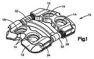
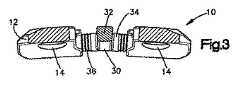
図1は、1つの主プレート30および2つのキャリジ要素12を有する本発明の固定システム10の一実施形態を示す斜視図である。固定システム10は、図2にその平面図で示され、図3にその側面図で示されている。固定システム10は、長手方向軸線A−Aおよび長さ「L」を有し、図4および図5に関連してより詳細に後述するように少なくとも1つのキャリジ要素12を有している。キャリジ要素12は、骨ファスナ(図示せず)の少なくとも一部を受入れる少なくとも1つのファスナ孔14を有している。固定システム10は、図6から図9Bに関連して詳細に後述するようにプレート30を有している。プレート30は、本体部分32と、該本体部分32から延びている少なくとも1つのアーム34とを有している。アーム34は、キャリジ要素12と係合するための、リッジ(畝)37を備えた係合部分36を有している。 FIG. 1 is a perspective view showing one embodiment of a
図4および図5を参照すると、各キャリジ要素12は、該キャリジ要素を骨セグメントに取付けることができる骨ファスナを受入れるための少なくとも1つのファスナ孔14を有している。図4および図5に示す実施形態では、各キャリジ要素12は2つのファスナ孔14を有している。骨ファスナは、明瞭化のため図示を省略してある。ファスナ孔14には、骨ファスナがファスナ孔から抜け出ることを防止する係留クリップ15を嵌装することもできる。係留クリップの詳細、材料および嵌装方法は、上記特許文献1(この全開示は本願に援用する)に開示されている。 Referring to FIGS. 4 and 5, each
キャリジ要素12は更に、プレート30の少なくとも一部を受入れる少なくとも1つのチャネル16を有しており、これらの係合については、より詳細に後述する。チャネル16は開口17A、17Bを有し、かつキャリジ要素12の本体を貫通する通路の少なくとも一部を通って延びている。またチャネル16は、両開口17A、17Bの間で延びている切除部分20を有している。切除部分20は、切除高さHcを有している。各開口17A、17Bはほぼ円形の形状を有し、同様な形状をもつプレート30のアーム34を受入れる。各開口17A、17Bはまた、縁部21A、21Bを有している。チャネル16ははまた、内面18と、該内面18とは反対側に配置された、キャリジ要素12の外面19とを有している。ここに示す実施形態では、各キャリジ要素12は2つのチャネル16を有し、各チャネル16は2つの開口17を有している。しかしながら、キャリジ要素に1つまたは3つ以上のチャネル16を設け、それぞれに異なる数の開口を設けることを考え得ることは明白である。このような変更は、当業者が考え得るものである。
キャリジ要素12はまた、上面13Aおよび下面13Bを有している。図5により明瞭に示すように、一方の面または両方の面13A、13Bはキャリジ要素12の長さ方向に沿って全体として湾曲している。このような湾曲は、キャリジ要素12が、所望の身体部位すなわち骨セグメントによりぴったり一致できるようにする点で有利である。
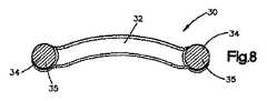
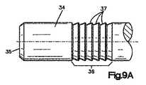
図6から図9Bには、プレート30の一実施形態が示されている。図6はプレート30の平面図、図7はプレート30の正面図、および図8はプレート30の側面図である。図9A、図9Bは、プレート30の係合部分36の拡大図である。主プレート30は、本体部分32、少なくとも1つのアーム34、および長手方向軸線B−Bを有している。アーム34は本体部分32から横方向にかつ長手方向軸線B−Bから離れる方向に延びており、かつキャリジ要素12のチャネル16内に少なくとも部分的に受入れられるサイズおよび寸法を有している。アーム34はまた、端部35を有している。 An embodiment of the
アーム34は更に係合部分36を有し、該係合部分36はリッジ37を備えている。図9Aおよび図9Bにより詳細に示すように、各リッジ37は、前面39と、後面38と、これらの間に位置する頂部33とを有している。前面39および後面38は、これらが係合部分36の長さ方向に沿って交互に位置するようにして、係合部分36に配置されている。従って、得られる係合部分は、一方から見たときに連続前面39を有し、かつ他方から見たときに連続後面38を有する。 The
係合部分36内のリッジ37は、実質的に同サイズでも良く、または異なるサイズにすることもできる。係合部分36のサイズは、単一プレート30および/または単一固定システム10の異なるアーム34で異ならせることができる。1つのアーム34に2つ以上の係合部分36を設けることができる。各頂部33は尖った形状にすることもできるし、実質的に丸めることもできる。ほぼ円形の横断面をもつアーム34の場合には、このような各アーム34の最大横断面直径は頂部33が有するように構成できる。 The
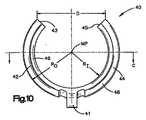
図10から図12には、係合クリップ40の一実施形態が示されており、図10はその平面図、図11はその断面図および図12はその側面図である。概略的に、各キャリジ要素12には、プレート30のアーム34とキャリジ要素12のチャネル16との間の確実な係合を行なうための少なくとも1つの係合クリップ40が設けられる。図10から図12に示す実施形態では、係合クリップ40は2つの弧状プロング42、44を有する。これらのプロング42、44は、それぞれ端部43、45を備え、両端部43、45の間の距離は「D」である。この距離「D」は、キャリジ要素12の切除部分20の高さ「Hc」と実質的に同じである。 10 to 12 show an embodiment of the
図11は、図10の係合クリップ40のC−C線に沿う断面図である。この図面から理解されようが、プロング42、44は、4つの面47、48、49、50をもつ多角形の断面形状を有している。より詳細に後述するように、内面47はリッジ37の前面39と係合し、側面49はリッジ37の後面38と係合する。また、内面47および側面49の寸法は、それぞれ、前面39および後面38の寸法に実質的に等しい。 FIG. 11 is a cross-sectional view taken along line CC of the
係合クリップ40はまた、中心点MP、内径RIおよび外径ROを有している。内径RIは、中心点MPから、内面47と側面49との間の縁部60までの距離として定義される。また、外径ROは、中心点MPから、外面48と側面50との間の縁部61までの距離として定義される。The
キャリジ要素12への係合クリップ40の係合が、部分拡大斜視図である図13および図14に示されている。キャリジ要素12が明瞭化された形態で描かれている図13に示すように、係合クリップ40は、該係合クリップ40がチャネル16の内面18に沿って配置されるようにしてキャリジ要素12と係合する。チャネル16は、係合クリップ40の少なくとも一部を受入れる内面18に沿って配置された溝50およびノッチ(図示せず)を有している。プロング42、44の一部が溝50内に挿入され、保持要素41がノッチ内に挿入される。この結果、係合クリップ40がキャリジ要素12内に固定的に座合され、かつ保持要素41がノッチ内に挿入されて、キャリジ要素12に対する係合クリップ40の回転が防止される点で好ましい。キャリジ要素12への係合クリップ40の係合は、キャリジ要素12の一部を破断して、図14にも示されている。 The engagement of the
一般的には、少なくとも1つのキャリジ要素12が、特にプレート30の係合部分(単一または複数)36でプレート30と係合する。係合クリップ40は、係合部分36のリッジ37と係合する。クリップ40が単一方向で連続リッジ37とのみ係合するように、リッジ37が配置され、かつ係合クリップ40が寸法およびサイズを有している。このような関係にすることにより得られる効果は、キャリジ要素12がプレート30に対して一方向に並進可能になることである。例えば、図14に示すキャリジ要素12およびプレート30は、係合クリップ40が、現に座合している位置よりも左方の連続リッジ37とのみ係合する態様で、係合される。前述のように、この一方向関係は、リッジ37の面38、39および係合クリップ40のクリッププロング42、44のサイズを、係合クリップ40がひとたび第一リッジ37Aから第二リッジ37Bに並進したならば、係合クリップが再び第一リッジ37Aと係合しないように定める(クリップ40は、プロング42、44を介して他方向に並進するに過ぎない)。リッジ37は「漸次抵抗(progressive resistance)」フォーマットで配置されており、一方向並進固定の詳細に加え、「漸次抵抗」フォーマットの詳細および長所が、上記特許文献2(この全開示は本願に援用する)に開示されている。 In general, at least one
図15Aから図15Cには、第一リッジ37Aから第二リッジ37Bに並進する係合クリップ40の漸進(progression)が示されている。図15Aに示すように、係合クリップ40は、該クリップ40の側面49がリッジ37Aの後面に隣接しかつクリップ40の内面47がリッジ37Aの前面39Bに隣接した状態で、リッジ37Aと係合している。図示の方向に力「F」が加えられると、クリップ40が拡げられて、第二リッジ37Bの方向に並進する。より詳しくは、クリップ40(該クリップ40は、後述のような弾性材料で作られている)の拡大はプロング42、44(図10参照)の可撓性により生じ、この場合、端部43、45が、中心点MPから離れるように外方に押しやられる。図15Bにはクリップ40の拡大が示されており、この場合、クリップ40は、力「F」が加えられると、頂部33Aから離れる方向に並進し、リッジ37Cに向かう。このとき、クリップ40の内面47はリッジの前面39と摺動係合する。クリップ40の縁部60がリッジの前面39Bに沿って、頂部37Bを通過するようにクリップ40が充分に押圧されると、クリップ40は、図15Cに示すように第二リッジ37Bと係合するようにスナップ嵌合される。しかしながら、力「F」がクリップ40を第二リッジ37Bの方向に移動させるには充分な大きさであるが、縁部60が頂部33Bを通過するように押しやるには不充分であるときは、クリップ40はその材料の弾性により収縮し、図15Aに示す位置に戻ることに留意することが重要である。また、図15Cに示すクリップ40は、外科医の介入なくしてリッジ37Aに戻ることがないことに留意することも重要である。クリップ40がひとたび図15Cに示す位置に移動されたならば、クリップ40は、外科医の介入なくして図15Aおよび図15Bの位置に並進して戻ることはない。 15A to 15C show the progression of the
身体部位での隣接椎骨を含む脊椎用途に使用する場合には、外科医は、最初に、椎間板の少なくとも一部を除去する。椎骨間にスペーサまたは他の材料を挿入する。次に、外科医は、第一キャリジ要素12Aが第一椎骨と係合しかつ第二キャリジ要素12Bが第二椎骨と係合するようにして、固定システム10を身体部位に隣接して配置する。身体部位に隣接してシステム10を配置する段階の前または後の任意の時点で、外科医は、システム10を手で圧縮または拡大させて、全長を減少または増大させる。システム10がひとたび所定位置に配置されたならば、外科医は、骨ファスナ(図示せず)をファスナ孔14を通して椎骨内に挿入することにより、キャリジ要素12A、12Bをそれぞれの椎骨に固定的に取付けることができる。また、外科医は、この時点で術中に、システム10を手で圧縮または拡大できる。次に、外科医は、切開部位を閉じる。 When used for spinal applications involving adjacent vertebrae at a body site, the surgeon first removes at least a portion of the intervertebral disc. Insert a spacer or other material between the vertebrae. The surgeon then positions the
術後に、キャリジ要素12は、手術部位でシステム10に加えられた力に応答して、プレート30に対して並進する。例えば、体内への移植後にサイズまたは強度が縮小または低下する椎骨間材料を使用する場合は、椎骨は、変位しおよび/または互いに近付くようにさまよう傾向を有する。本願に開示するシステム10は、係合クリップ40がプレート30の連続リッジと係合できるようにすることにより、キャリジ要素12が軸線方向に並進できるようにすることによって、このような力に応答できる。この結果、システム10は、手術部位での術後力に応答し、および/または椎骨間材料に作用する充分な圧縮を維持して、椎骨間の押出しを防止しかつ骨成長および/または固着を促進すべく充分な度合いに圧縮できる。 After surgery, the
システム10は直列に使用するか、または他の用具と組合せて使用することを考えることもできる。また、固定システム10は、2つ、3つまたはこれより多くの椎骨に、連続的または非連続的に使用することも考えられる。当業者ならば、プレート、キャリジ要素および他のコンポーネンツの相対サイズ等のシステムの他の変更を考えることができよう。 It can also be envisaged that the
前述の方法および長所は脊椎用途に関連して説明したが、本願に開示したシステム10は、関節および長骨の骨折等の他の体部分に使用することも考えられる。当業者ならば、他の手術用途を考えることができよう。 Although the foregoing methods and advantages have been described in connection with spinal applications, the
係合クリップ40は、加えられた力に応答してプロング42、44を分離できる材料で形成できるが、力を除去したときにプロングの元の形状に戻ることができるように弾性をもたせることもできる。係合クリップ40に適した材料の一例として、エルギロイ(elgiloy)がある。係留クリップ15も同じ材料で形成できる。 The
本願に開示する各ファスナ、固定プレート、キャリジ要素および他のコンポーネンツは、チタン・アルミニウム・ニオブのようなチタン合金で形成でき、これらの合金は陽極酸化処理することができる。本願に開示するプレートおよびファスナの各々に使用できる一材料として、約4.52gm/ccの密度、約105GPaの弾性係数、約900MPaの最大引っ張り強度、約800MPaの降伏強度を有するTi・6Al・7Nbがある。また、ファスナの表面はバリがなく、全ての鋭い縁部は最大で0.1mmとなるように丸められる。 Each fastener, fixed plate, carriage element and other components disclosed herein can be formed of a titanium alloy such as titanium, aluminum, and niobium, and these alloys can be anodized. One material that can be used for each of the plates and fasteners disclosed herein is Ti · 6Al · 7Nb having a density of about 4.52 gm / cc, an elastic modulus of about 105 GPa, a maximum tensile strength of about 900 MPa, and a yield strength of about 800 MPa. There is. The fastener surface is burr-free and all sharp edges are rounded to a maximum of 0.1 mm.
図16は、長手方向軸線D−Dを有する固定システムの他の実施形態を示す斜視図である。キャリジ要素112は、図1から図15Cに関連して前述したキャリジ要素12と実質的に同じである。この実施形態では、プレート130は軸線方向に延びたアーム134を有し、該アーム134は、アーム34の係合部分36と実質的に同じである係合部分136を備えている。キャリジ要素112のチャネル116内には、係合クリップ40も配置されている。図16に示す実施形態と前の実施形態との間の大きな差異は、本体部分132がI形バーの形状ではなく、体表面に一致するように構成された細長プレートの形状をなしている。本体部分132には少なくとも1つの窓150が設けられており、図16の実施形態には3つのこのような窓150が示されている。各窓150には、該窓150内で長手方向に摺動できる中間キャリジブロック160が設けられている。各キャリジブロック160はファスナ孔162を有し、該ファスナ孔162内には、骨ファスナ(図示せず)の少なくとも一部と係合する係留クリップ164が配置されている。窓150とキャリジブロック160との間の接触面は鳩尾状であり、キャリジ160が窓150内に組付けられた後に、キャリジ160が緩むことを防止する。図16に示す実施形態は、脊柱に沿う3つ以上の連続椎骨の並進固定を達成できる。中間キャリジヨウ素および多レベル固定の更なる詳細、材料および方法が、上記特許文献3(この全開示は本願に援用する)に開示されている。 FIG. 16 is a perspective view illustrating another embodiment of a fixation system having a longitudinal axis DD.
上記説明および図示は、本発明の原理を用いて設計されかつ組立てられる並進プレートの構造の例として行ったものであることに留意すべきである。当業者ならば、これらの例は、開示された1つ以上の特徴を用いる固定組立体が、特定患者の要望により作られる点で非制限的なものであることは理解されよう。かくして、開示した特徴は、本質的に「モジュラ」である。 It should be noted that the above description and illustrations have been made as an example of the structure of a translation plate designed and assembled using the principles of the present invention. Those skilled in the art will appreciate that these examples are non-limiting in that a fixation assembly using one or more of the disclosed features can be made according to the needs of a particular patient. Thus, the disclosed features are “modular” in nature.
上記説明は、特許請求する本発明の最良モードを述べたものであり、かつ特許請求の範囲に記載の要素の例を示すことにより、当業者が製造しかつ使用することができる特許請求に係る発明を説明したものである。本発明の範囲は特許請求の範囲の記載により定められるものであり、当業者に明白な他の例を包含するものである。本願の出願日より前または出願日より後に利用できたこのような他の例は、特許請求の範囲の記載とは異ならない構造的要素を有するか、特許請求の範囲の記載とは実質的に異ならない均等の構造的要素を有する場合には、特許請求の範囲内に包含されるものである。 The above description describes the best mode of the claimed invention and relates to claims that can be made and used by those skilled in the art by illustrating examples of the elements recited in the claims. The invention has been described. The scope of the present invention is defined by the appended claims, and includes other examples that will be apparent to those skilled in the art. Such other examples that could be used before or after the filing date of the present application have structural elements that do not differ from the claims, or are substantially different from the claims. Any equivalent structural element that does not differ is intended to be encompassed within the scope of the claims.
本発明を特定実施形態に関連して図示しかつ説明したが、実際に使用されかつ特定環境および手術条件に特に適合する種々の付加、置換または形態、構造、プロポーション、材料およびコンポーネンツの変更は、本発明の精神および範囲を逸脱することなく、本願に説明した実施形態になし得るものであることを理解すべきである。従って、本願に開示された実施形態は本発明の原理の単なる例示であることを理解すべきである。本発明の原理を具現しかつ本発明の精神および範囲内に包含される他の種々の変更は、当業者がなし得るものである。 While the invention has been illustrated and described in connection with specific embodiments, various additions, substitutions or configurations, constructions, proportions, materials and component modifications that are actually used and particularly adapted to specific environments and surgical conditions are It should be understood that the embodiments described herein can be made without departing from the spirit and scope of the invention. Accordingly, it should be understood that the embodiments disclosed herein are merely illustrative of the principles of the present invention. Various other modifications that embody the principles of the invention and that fall within the spirit and scope of the invention may be made by those skilled in the art.
10、110 固定システム
12、112 キャリジ要素
14、162 ファスナ孔
15、164 係留クリップ
16 チャネル
30 主プレート
32 本体部分
34、134 アーム
36 係合部分
37 リッジ
40 係合クリップ10, 110
Claims (20)
Translated fromJapanese一チャネル内に挿入可能な第一アームを備えた第一プレートを更に有し、
第一アームは第一係合部分を備え、第一係合部分は、固定要素と係合するように構成された一連のリッジを備え、
第一キャリジ要素は、第一プレートに対して軸線方向の一方向のみに並進するように構成されていることを特徴とする固定システム。Having a first carriage element, the first carriage element being capable of receiving one or more fasteners and comprising a first channel, wherein at least one securing element is disposed in the first channel;
A first plate with a first arm insertable into the channel;
The first arm includes a first engagement portion, the first engagement portion includes a series of ridges configured to engage the fixation element;
The first carriage element is configured to translate in only one axial direction relative to the first plate.
1つ以上の骨ファスナを受入れることができる第一キャリジ要素および第二キャリジ要素を有し、各キャリジ要素はチャネルを備え、該チャネル内には少なくとも1つの固定要素を配置でき、
一チャネル内に挿入可能なアームを備えた第一プレートを更に有し、
各アームは第一係合部分を備え、第一係合部分は、固定要素と係合するように構成された一連のリッジを備え、
(b)組立体を所望の身体部位に隣接して位置決めする段階と、
(c)第一キャリジ要素を少なくとも1つの骨ファスナを用いて第一骨セグメントに取付けかつ第二キャリジ要素を少なくとも1つの骨ファスナを用いて第二骨セグメントに取付ける段階と、
(d)前記システムを手術部位で並進できるようにする段階とを更に有することを特徴とする複数の骨セグメントを固定する方法。(A) providing a fixing system, the fixing system comprising:
Having a first carriage element and a second carriage element capable of receiving one or more bone fasteners, each carriage element comprising a channel within which at least one fixation element can be disposed;
A first plate with an arm insertable in one channel;
Each arm includes a first engagement portion, the first engagement portion includes a series of ridges configured to engage a fixation element;
(B) positioning the assembly adjacent to the desired body part;
(C) attaching the first carriage element to the first bone segment using at least one bone fastener and attaching the second carriage element to the second bone segment using at least one bone fastener;
(D) fixing the plurality of bone segments further comprising translating the system at a surgical site.
一チャネル内に挿入可能なアームを備えた少なくとも1つのプレートを更に有し、
各アームは第一係合部分を備え、第一係合部分は、固定要素と係合するように構成された一連のリッジを備え、
少なくとも2つのキャリジ要素は、実質的に異なるサイズを有していることを特徴とする固定システムキット。Having a plurality of carriage elements capable of receiving one or more bone fasteners, each carriage element comprising a first channel, wherein at least one fixation element is disposed within the first channel;
And further comprising at least one plate with an arm insertable in one channel;
Each arm includes a first engagement portion, the first engagement portion includes a series of ridges configured to engage a fixation element;
A fixation system kit, wherein the at least two carriage elements have substantially different sizes.
Applications Claiming Priority (3)
| Application Number | Priority Date | Filing Date | Title |
|---|---|---|---|
| US11/078,802 | 2005-03-11 | ||
| US11/078,802US7479143B2 (en) | 2005-03-11 | 2005-03-11 | Unidirectional fixation device |
| PCT/US2006/007661WO2006098908A1 (en) | 2005-03-11 | 2006-03-03 | Unidirectional fixation device |
Publications (3)
| Publication Number | Publication Date |
|---|---|
| JP2008532628Atrue JP2008532628A (en) | 2008-08-21 |
| JP2008532628A5 JP2008532628A5 (en) | 2009-04-23 |
| JP4940228B2 JP4940228B2 (en) | 2012-05-30 |
Family
ID=36579599
Family Applications (1)
| Application Number | Title | Priority Date | Filing Date |
|---|---|---|---|
| JP2008500777AExpired - Fee RelatedJP4940228B2 (en) | 2005-03-11 | 2006-03-03 | Unidirectional fixture |
Country Status (12)
| Country | Link |
|---|---|
| US (1) | US7479143B2 (en) |
| EP (1) | EP1871256A1 (en) |
| JP (1) | JP4940228B2 (en) |
| KR (1) | KR20070117608A (en) |
| CN (1) | CN100512771C (en) |
| AU (1) | AU2006223600A1 (en) |
| BR (1) | BRPI0609001A2 (en) |
| CA (1) | CA2600742A1 (en) |
| CO (1) | CO6190590A2 (en) |
| NZ (1) | NZ561415A (en) |
| TW (1) | TWI324917B (en) |
| WO (1) | WO2006098908A1 (en) |
Cited By (1)
| Publication number | Priority date | Publication date | Assignee | Title |
|---|---|---|---|---|
| JP2011010792A (en)* | 2009-07-01 | 2011-01-20 | Japan Medical Materials Corp | Surgical instrument for osteosynthesis |
Families Citing this family (30)
| Publication number | Priority date | Publication date | Assignee | Title |
|---|---|---|---|---|
| US7621942B2 (en)* | 2005-03-21 | 2009-11-24 | Zimmer Spine, Inc. | Variable geometry occipital fixation plate |
| US7993380B2 (en)* | 2005-03-31 | 2011-08-09 | Alphatel Spine, Inc. | Active compression orthopedic plate system and method for using the same |
| US8070749B2 (en) | 2005-05-12 | 2011-12-06 | Stern Joseph D | Revisable anterior cervical plating system |
| US20070123881A1 (en)* | 2005-10-26 | 2007-05-31 | Ralph James D | Off-set bone plates |
| WO2007098188A2 (en)* | 2006-02-21 | 2007-08-30 | Life Spine, Inc. | Structure for joining and retaining multi-part orthopedic implants |
| US7699874B2 (en)* | 2006-03-01 | 2010-04-20 | Warsaw Orthopedic, Inc. | Low profile spinal rod connector system |
| US7901433B2 (en)* | 2006-10-04 | 2011-03-08 | Zimmer Spine, Inc. | Occipito-cervical stabilization system and method |
| US8262710B2 (en) | 2006-10-24 | 2012-09-11 | Aesculap Implant Systems, Llc | Dynamic stabilization device for anterior lower lumbar vertebral fusion |
| US20080147124A1 (en)* | 2006-10-31 | 2008-06-19 | Haidukewych George J | Bone plate system with slidable compression holes |
| US8206390B2 (en)* | 2006-11-02 | 2012-06-26 | Warsaw Orthopedic, Inc. | Uni-directional ratcheting bone plate assembly |
| US8147527B2 (en)* | 2006-11-28 | 2012-04-03 | Zimmer Spine, Inc. | Adjustable occipital plate |
| US8246662B2 (en)* | 2006-12-27 | 2012-08-21 | Zimmer Spine, Inc. | Modular occipital plate |
| US8636737B2 (en)* | 2006-12-27 | 2014-01-28 | Zimmer Spine, Inc. | Modular occipital plate |
| US8388663B2 (en) | 2007-09-13 | 2013-03-05 | Stryker Spine | Dynamic cervical plate |
| WO2009055537A1 (en) | 2007-10-23 | 2009-04-30 | K2M, Inc. | Dynamic cervical plate |
| EP2224868B1 (en) | 2007-11-21 | 2014-07-30 | Globus Medical, Inc. | Cervical spine stabilization system with extendable plates |
| US20090210008A1 (en)* | 2008-02-20 | 2009-08-20 | Life Spine, Inc. | Modular spine plate with projection and socket interface |
| WO2010025405A1 (en)* | 2008-08-29 | 2010-03-04 | Life Spine, Inc. | Single-sided dynamic spine plates |
| US8808333B2 (en) | 2009-07-06 | 2014-08-19 | Zimmer Gmbh | Periprosthetic bone plates |
| US8834532B2 (en) | 2009-07-07 | 2014-09-16 | Zimmer Gmbh | Plate for the treatment of bone fractures |
| US10342583B2 (en) | 2010-10-01 | 2019-07-09 | K2M, Inc. | Dynamic plate with inserts |
| US11123117B1 (en) | 2011-11-01 | 2021-09-21 | Nuvasive, Inc. | Surgical fixation system and related methods |
| US9579128B2 (en) | 2013-07-19 | 2017-02-28 | K2M, Inc. | Translational plate and compressor instrument |
| US9468479B2 (en) | 2013-09-06 | 2016-10-18 | Cardinal Health 247, Inc. | Bone plate |
| US11253299B2 (en) | 2013-10-28 | 2022-02-22 | Jace Medical, Llc | Orthopaedic fixation devices, systems and methods |
| US9681903B2 (en) | 2013-11-15 | 2017-06-20 | K2M, Inc. | Clip for dynamic spinal plate |
| WO2016029008A1 (en) | 2014-08-20 | 2016-02-25 | Jace Medical, Llc | Implant positioning devices and methods |
| US10130358B2 (en) | 2015-10-07 | 2018-11-20 | Arthrex, Inc. | Devices for controlling the unloading of superelastic and shape memory orthopedic implants |
| KR101886341B1 (en)* | 2017-06-14 | 2018-08-07 | 인하대학교 산학협력단 | Segmented plate assembly for remedy of fracture bone |
| TWI736417B (en)* | 2020-09-15 | 2021-08-11 | 財團法人工業技術研究院 | Flexible bone fixation device |
Citations (5)
| Publication number | Priority date | Publication date | Assignee | Title |
|---|---|---|---|---|
| US3385299A (en)* | 1965-10-23 | 1968-05-28 | New Res And Dev Lab Inc | Wound clip |
| US5616142A (en)* | 1994-07-20 | 1997-04-01 | Yuan; Hansen A. | Vertebral auxiliary fixation device |
| US5964763A (en)* | 1997-02-14 | 1999-10-12 | Incavo; Stephen J. | Incrementally adjustable tibial osteotomy fixation device and method |
| WO2003063714A2 (en)* | 2002-02-01 | 2003-08-07 | Spinal Concepts, Inc. | Spinal plate system for stabilizing a portion of a spine |
| JP2004530482A (en)* | 2001-06-04 | 2004-10-07 | マイケルスン、ガーリー、ケィー | Dynamic anterior cervical vertebral dynamic plate fixation system with movable segment, instrument, and method of attachment |
Family Cites Families (9)
| Publication number | Priority date | Publication date | Assignee | Title |
|---|---|---|---|---|
| DE2621175C3 (en) | 1976-05-11 | 1979-04-19 | Erhard Dr. 1000 Berlin Westerhoff | Device for the gradual lengthening of limbs |
| GB8718708D0 (en)* | 1987-08-07 | 1987-09-16 | Mehdian S M H | Apparatus for treatment of spinal disorders |
| US5470333A (en)* | 1993-03-11 | 1995-11-28 | Danek Medical, Inc. | System for stabilizing the cervical and the lumbar region of the spine |
| US6513887B2 (en)* | 2001-01-05 | 2003-02-04 | Coin Acceptors, Inc. | Spring clip retainer for vending machine storage compartments |
| US7044952B2 (en) | 2001-06-06 | 2006-05-16 | Sdgi Holdings, Inc. | Dynamic multilock anterior cervical plate system having non-detachably fastened and moveable segments |
| US6932820B2 (en)* | 2002-01-08 | 2005-08-23 | Said G. Osman | Uni-directional dynamic spinal fixation device |
| US6602257B1 (en)* | 2002-06-24 | 2003-08-05 | Jeffrey J. Thramann | Cervical plate |
| WO2004008978A1 (en) | 2002-07-24 | 2004-01-29 | Nas Spine, Inc. | Compressible fixation apparatus for spinal surgery |
| US20050049595A1 (en) | 2003-09-03 | 2005-03-03 | Suh Sean S. | Track-plate carriage system |
- 2005
- 2005-03-11USUS11/078,802patent/US7479143B2/enactiveActive
- 2006
- 2006-03-03AUAU2006223600Apatent/AU2006223600A1/ennot_activeAbandoned
- 2006-03-03NZNZ561415Apatent/NZ561415A/enunknown
- 2006-03-03KRKR1020077021948Apatent/KR20070117608A/ennot_activeAbandoned
- 2006-03-03BRBRPI0609001Apatent/BRPI0609001A2/ennot_activeIP Right Cessation
- 2006-03-03WOPCT/US2006/007661patent/WO2006098908A1/enactiveApplication Filing
- 2006-03-03JPJP2008500777Apatent/JP4940228B2/ennot_activeExpired - Fee Related
- 2006-03-03CACA002600742Apatent/CA2600742A1/ennot_activeAbandoned
- 2006-03-03EPEP06736906Apatent/EP1871256A1/ennot_activeWithdrawn
- 2006-03-03CNCNB2006800152633Apatent/CN100512771C/ennot_activeExpired - Fee Related
- 2006-03-10TWTW095108244Apatent/TWI324917B/ennot_activeIP Right Cessation
- 2007
- 2007-10-03COCO07103465Apatent/CO6190590A2/ennot_activeApplication Discontinuation
Patent Citations (5)
| Publication number | Priority date | Publication date | Assignee | Title |
|---|---|---|---|---|
| US3385299A (en)* | 1965-10-23 | 1968-05-28 | New Res And Dev Lab Inc | Wound clip |
| US5616142A (en)* | 1994-07-20 | 1997-04-01 | Yuan; Hansen A. | Vertebral auxiliary fixation device |
| US5964763A (en)* | 1997-02-14 | 1999-10-12 | Incavo; Stephen J. | Incrementally adjustable tibial osteotomy fixation device and method |
| JP2004530482A (en)* | 2001-06-04 | 2004-10-07 | マイケルスン、ガーリー、ケィー | Dynamic anterior cervical vertebral dynamic plate fixation system with movable segment, instrument, and method of attachment |
| WO2003063714A2 (en)* | 2002-02-01 | 2003-08-07 | Spinal Concepts, Inc. | Spinal plate system for stabilizing a portion of a spine |
Cited By (1)
| Publication number | Priority date | Publication date | Assignee | Title |
|---|---|---|---|---|
| JP2011010792A (en)* | 2009-07-01 | 2011-01-20 | Japan Medical Materials Corp | Surgical instrument for osteosynthesis |
Also Published As
| Publication number | Publication date |
|---|---|
| JP4940228B2 (en) | 2012-05-30 |
| EP1871256A1 (en) | 2008-01-02 |
| US7479143B2 (en) | 2009-01-20 |
| NZ561415A (en) | 2010-08-27 |
| KR20070117608A (en) | 2007-12-12 |
| CA2600742A1 (en) | 2006-09-21 |
| US20060217724A1 (en) | 2006-09-28 |
| CN101170956A (en) | 2008-04-30 |
| AU2006223600A1 (en) | 2006-09-21 |
| CN100512771C (en) | 2009-07-15 |
| TW200701938A (en) | 2007-01-16 |
| CO6190590A2 (en) | 2010-08-19 |
| TWI324917B (en) | 2010-05-21 |
| WO2006098908A1 (en) | 2006-09-21 |
| BRPI0609001A2 (en) | 2016-11-08 |
Similar Documents
| Publication | Publication Date | Title |
|---|---|---|
| JP4940228B2 (en) | Unidirectional fixture | |
| US8641765B2 (en) | Posterior spinal implant system | |
| JP5166035B2 (en) | Unidirectional linear movement system for bone fixation | |
| US7666185B2 (en) | Translatable carriage fixation system | |
| US7819903B2 (en) | Spinal fixation plate | |
| US7112222B2 (en) | Anterior lumbar interbody fusion cage with locking plate | |
| US7186254B2 (en) | Methods and apparatus for promoting fusion of vertebrae | |
| US9114023B2 (en) | Interbody fusion device with snap on anterior plate and associated methods | |
| JP2008532627A (en) | Translation plate with spring beam holder | |
| JP2008532626A (en) | Translational scissor plate fixing system | |
| US20150282947A1 (en) | Vertebral body replacement |
Legal Events
| Date | Code | Title | Description |
|---|---|---|---|
| A521 | Request for written amendment filed | Free format text:JAPANESE INTERMEDIATE CODE: A523 Effective date:20090302 | |
| A621 | Written request for application examination | Free format text:JAPANESE INTERMEDIATE CODE: A621 Effective date:20090302 | |
| A977 | Report on retrieval | Free format text:JAPANESE INTERMEDIATE CODE: A971007 Effective date:20110727 | |
| A131 | Notification of reasons for refusal | Free format text:JAPANESE INTERMEDIATE CODE: A131 Effective date:20110808 | |
| A521 | Request for written amendment filed | Free format text:JAPANESE INTERMEDIATE CODE: A523 Effective date:20111107 | |
| TRDD | Decision of grant or rejection written | ||
| A01 | Written decision to grant a patent or to grant a registration (utility model) | Free format text:JAPANESE INTERMEDIATE CODE: A01 Effective date:20120130 | |
| A01 | Written decision to grant a patent or to grant a registration (utility model) | Free format text:JAPANESE INTERMEDIATE CODE: A01 | |
| A61 | First payment of annual fees (during grant procedure) | Free format text:JAPANESE INTERMEDIATE CODE: A61 Effective date:20120227 | |
| FPAY | Renewal fee payment (event date is renewal date of database) | Free format text:PAYMENT UNTIL: 20150302 Year of fee payment:3 | |
| R150 | Certificate of patent or registration of utility model | Free format text:JAPANESE INTERMEDIATE CODE: R150 | |
| R250 | Receipt of annual fees | Free format text:JAPANESE INTERMEDIATE CODE: R250 | |
| R250 | Receipt of annual fees | Free format text:JAPANESE INTERMEDIATE CODE: R250 | |
| R250 | Receipt of annual fees | Free format text:JAPANESE INTERMEDIATE CODE: R250 | |
| LAPS | Cancellation because of no payment of annual fees |