JP2008531170A - Medical device system with optical fiber load detection capability - Google Patents
Medical device system with optical fiber load detection capabilityDownload PDFInfo
- Publication number
- JP2008531170A JP2008531170AJP2007557615AJP2007557615AJP2008531170AJP 2008531170 AJP2008531170 AJP 2008531170AJP 2007557615 AJP2007557615 AJP 2007557615AJP 2007557615 AJP2007557615 AJP 2007557615AJP 2008531170 AJP2008531170 AJP 2008531170A
- Authority
- JP
- Japan
- Prior art keywords
- distal end
- sensor
- fiber optic
- optical fiber
- force
- Prior art date
- Legal status (The legal status is an assumption and is not a legal conclusion. Google has not performed a legal analysis and makes no representation as to the accuracy of the status listed.)
- Granted
Links
Images


Classifications
- G—PHYSICS
- G01—MEASURING; TESTING
- G01L—MEASURING FORCE, STRESS, TORQUE, WORK, MECHANICAL POWER, MECHANICAL EFFICIENCY, OR FLUID PRESSURE
- G01L1/00—Measuring force or stress, in general
- G01L1/24—Measuring force or stress, in general by measuring variations of optical properties of material when it is stressed, e.g. by photoelastic stress analysis using infrared, visible light, ultraviolet
- G01L1/242—Measuring force or stress, in general by measuring variations of optical properties of material when it is stressed, e.g. by photoelastic stress analysis using infrared, visible light, ultraviolet the material being an optical fibre
- G01L1/246—Measuring force or stress, in general by measuring variations of optical properties of material when it is stressed, e.g. by photoelastic stress analysis using infrared, visible light, ultraviolet the material being an optical fibre using integrated gratings, e.g. Bragg gratings
- A—HUMAN NECESSITIES
- A61—MEDICAL OR VETERINARY SCIENCE; HYGIENE
- A61B—DIAGNOSIS; SURGERY; IDENTIFICATION
- A61B5/00—Measuring for diagnostic purposes; Identification of persons
- A61B5/06—Devices, other than using radiation, for detecting or locating foreign bodies ; Determining position of diagnostic devices within or on the body of the patient
- A61B5/065—Determining position of the probe employing exclusively positioning means located on or in the probe, e.g. using position sensors arranged on the probe
- A—HUMAN NECESSITIES
- A61—MEDICAL OR VETERINARY SCIENCE; HYGIENE
- A61B—DIAGNOSIS; SURGERY; IDENTIFICATION
- A61B90/00—Instruments, implements or accessories specially adapted for surgery or diagnosis and not covered by any of the groups A61B1/00 - A61B50/00, e.g. for luxation treatment or for protecting wound edges
- A61B90/06—Measuring instruments not otherwise provided for
- A—HUMAN NECESSITIES
- A61—MEDICAL OR VETERINARY SCIENCE; HYGIENE
- A61B—DIAGNOSIS; SURGERY; IDENTIFICATION
- A61B90/00—Instruments, implements or accessories specially adapted for surgery or diagnosis and not covered by any of the groups A61B1/00 - A61B50/00, e.g. for luxation treatment or for protecting wound edges
- A61B90/90—Identification means for patients or instruments, e.g. tags
- A61B90/94—Identification means for patients or instruments, e.g. tags coded with symbols, e.g. text
- A61B90/96—Identification means for patients or instruments, e.g. tags coded with symbols, e.g. text using barcodes
- A—HUMAN NECESSITIES
- A61—MEDICAL OR VETERINARY SCIENCE; HYGIENE
- A61B—DIAGNOSIS; SURGERY; IDENTIFICATION
- A61B90/00—Instruments, implements or accessories specially adapted for surgery or diagnosis and not covered by any of the groups A61B1/00 - A61B50/00, e.g. for luxation treatment or for protecting wound edges
- A61B90/90—Identification means for patients or instruments, e.g. tags
- A61B90/98—Identification means for patients or instruments, e.g. tags using electromagnetic means, e.g. transponders
- A—HUMAN NECESSITIES
- A61—MEDICAL OR VETERINARY SCIENCE; HYGIENE
- A61B—DIAGNOSIS; SURGERY; IDENTIFICATION
- A61B18/00—Surgical instruments, devices or methods for transferring non-mechanical forms of energy to or from the body
- A61B18/04—Surgical instruments, devices or methods for transferring non-mechanical forms of energy to or from the body by heating
- A61B18/12—Surgical instruments, devices or methods for transferring non-mechanical forms of energy to or from the body by heating by passing a current through the tissue to be heated, e.g. high-frequency current
- A61B18/14—Probes or electrodes therefor
- A61B18/1492—Probes or electrodes therefor having a flexible, catheter-like structure, e.g. for heart ablation
- A—HUMAN NECESSITIES
- A61—MEDICAL OR VETERINARY SCIENCE; HYGIENE
- A61B—DIAGNOSIS; SURGERY; IDENTIFICATION
- A61B90/00—Instruments, implements or accessories specially adapted for surgery or diagnosis and not covered by any of the groups A61B1/00 - A61B50/00, e.g. for luxation treatment or for protecting wound edges
- A61B90/06—Measuring instruments not otherwise provided for
- A61B2090/064—Measuring instruments not otherwise provided for for measuring force, pressure or mechanical tension
- A61B2090/065—Measuring instruments not otherwise provided for for measuring force, pressure or mechanical tension for measuring contact or contact pressure
- A—HUMAN NECESSITIES
- A61—MEDICAL OR VETERINARY SCIENCE; HYGIENE
- A61B—DIAGNOSIS; SURGERY; IDENTIFICATION
- A61B2562/00—Details of sensors; Constructional details of sensor housings or probes; Accessories for sensors
- A61B2562/02—Details of sensors specially adapted for in-vivo measurements
- A61B2562/0261—Strain gauges
- A61B2562/0266—Optical strain gauges
- A—HUMAN NECESSITIES
- A61—MEDICAL OR VETERINARY SCIENCE; HYGIENE
- A61B—DIAGNOSIS; SURGERY; IDENTIFICATION
- A61B5/00—Measuring for diagnostic purposes; Identification of persons
- A61B5/01—Measuring temperature of body parts ; Diagnostic temperature sensing, e.g. for malignant or inflamed tissue
- A61B5/015—By temperature mapping of body part
Landscapes
- Health & Medical Sciences (AREA)
- Life Sciences & Earth Sciences (AREA)
- Surgery (AREA)
- Engineering & Computer Science (AREA)
- Heart & Thoracic Surgery (AREA)
- Animal Behavior & Ethology (AREA)
- Veterinary Medicine (AREA)
- Public Health (AREA)
- General Health & Medical Sciences (AREA)
- Biomedical Technology (AREA)
- Pathology (AREA)
- Medical Informatics (AREA)
- Molecular Biology (AREA)
- Physics & Mathematics (AREA)
- Nuclear Medicine, Radiotherapy & Molecular Imaging (AREA)
- Oral & Maxillofacial Surgery (AREA)
- General Physics & Mathematics (AREA)
- Electromagnetism (AREA)
- Human Computer Interaction (AREA)
- Biophysics (AREA)
- Length Measuring Devices By Optical Means (AREA)
- Media Introduction/Drainage Providing Device (AREA)
Abstract
Translated fromJapaneseDescription
Translated fromJapanese本発明は、装置の遠位端と器官の壁組織との接触から生じる多次元力ベクトルを計算可能にする、器官を探査し、治療する装置に関するものである。 The present invention relates to a device for exploring and treating an organ that allows calculation of multidimensional force vectors resulting from contact between the distal end of the device and the wall tissue of the organ.
長年の間に、さまざまな器官または血管の探査及び治療がカテーテル・ベースの診断及び治療システムを利用して可能になってきた。こうしたカテーテルは、調査または治療される器官の空洞に通じる血管を介して導入するか、あるいは、代わりに、器官の壁に施された切開部分を介して直接導入することも可能である。こうして、患者は、一般に外科処置の切開による外傷及び長期保養時間を回避する。 Over the years, the exploration and treatment of various organs or blood vessels has become possible using catheter-based diagnostic and treatment systems. Such catheters can be introduced via blood vessels leading to the cavity of the organ to be investigated or treated, or alternatively, directly through an incision made in the wall of the organ. In this way, patients generally avoid trauma and long rest periods due to surgical incisions.
有効な診断または治療を施すため、最初に、極めて精密に処置すべきゾーンをマッピングしなければならないことが多い。こうしたマッピングは、例えば、心房細動の治療のため、心臓内の電流経路を選択的に切除することが求められる場合に実施される可能性がある。マッピング手順は、心臓周期全体にわたる心臓の周期的運動に起因する、治療すべきゾーンの位置確認の難しさによって複雑になる場合が多い。 In order to provide effective diagnosis or therapy, it is often necessary to first map the zone to be treated very precisely. Such mapping may be performed, for example, when it is desired to selectively ablate the current pathway in the heart for the treatment of atrial fibrillation. The mapping procedure is often complicated by the difficulty of locating the zone to be treated due to the periodic motion of the heart throughout the cardiac cycle.
血管または器官内部のマッピングを行うための既知のシステムについては、例えば、米国特許第6,546,271号(US−A−6546271)及び第6,226,542号(US−A−6226542)に記載がある。それらの特許に記載のカテーテルは、電磁、磁気、または、音響センサを用いて、空間内にカテーテルの遠位端の位置をマッピングし、その後、血管または器官内部の三次元描写像を作成する。 Known systems for mapping blood vessels or internal organs are described, for example, in US Pat. Nos. 6,546,271 (US-A-6546271) and 6,226,542 (US-A-6226542). There is a description. The catheters described in those patents use electromagnetic, magnetic, or acoustic sensors to map the position of the distal end of the catheter in space and then create a three-dimensional depiction of the interior of the blood vessel or organ.
こうした既知のマッピング・システムの欠点の1つは、カテーテルの手動フィードバック及び/またはインピーダンス測定に頼って、カテーテルが血管または器官内において適正に位置決めされると、判断するという点にある。これらのシステムでは、血管または器官との接触力が測定されないか、あるいは、真の壁位置を変える可能性のある、カテーテルによって器官または血管に加えられる接触力が検出されない。それどころか、既知のマッピング法は、臨床医の技能によっては時間がかかり、過剰な接触力によって生じる人為的な影響を補正することができない。 One disadvantage of these known mapping systems is that they rely on manual feedback and / or impedance measurements of the catheter to determine that the catheter is properly positioned within the blood vessel or organ. In these systems, the contact force with the blood vessel or organ is not measured, or the contact force applied to the organ or blood vessel by the catheter that may change the true wall position is not detected. On the contrary, known mapping methods are time consuming depending on the skill of the clinician and cannot correct the artificial effects caused by excessive contact forces.
従って、マッピング・カテーテルと器官または血管の壁との接触力を検出及び監視して、より迅速でより正確なマッピングを可能にするための装置及び方法を提供するのが望ましいであろう。さらに、プロセスの自動化を可能にして、その結果、例えば、接触力が所定の範囲内にある場合に限って、測定された電気生理学的値及び空間座標を記録することにより、これらの値の記録が改善されるようにする装置及び方法を提供するのが望ましいであろう。 Accordingly, it would be desirable to provide an apparatus and method for detecting and monitoring the contact force between a mapping catheter and an organ or vessel wall to enable faster and more accurate mapping. Furthermore, the process can be automated so that recording of these values is possible, for example by recording measured electrophysiological values and spatial coordinates only if the contact force is within a predetermined range. It would be desirable to provide an apparatus and method that would improve the performance.
血管または器官の組織分布がマッピングされると、同じかまたは異なるカテーテルを用いて、治療が施される。血管または器官に施される特定の治療に応じて、カテーテルには、RFアブレーション電極、回転カッティング・ヘッド、レーザ・アブレーション・システム、注射針、または、低温流体送達システムのような、いくつかのエンド・エフェクタのうちの任意のものを含むことが可能である。典型的なシステムについては、例えば、米国特許第6,120,520号(US−A−6120520)、第6,102,926号(US−A−6102926)、第5,575,787号(US−A−5575787)、第5,409,000号(US−A−5409000)、及び、第5,423,807(US−A−5423807)号に記載がある。 Once the tissue distribution of a blood vessel or organ is mapped, treatment is applied using the same or different catheters. Depending on the particular treatment being applied to the blood vessel or organ, the catheter may have several ends, such as an RF ablation electrode, a rotating cutting head, a laser ablation system, a needle, or a cryogenic fluid delivery system. It can include any of the effectors. Exemplary systems include, for example, US Pat. Nos. 6,120,520 (US-A-6120520), 6,102,926 (US-A-6102926), and 5,575,787 (US). -A-5575787), 5,409,000 (US-A-5409000), and 5,423,807 (US-A-5423807).
こうしたエンド・エフェクタの有効性は、エンド・エフェクタが器官または血管の壁の組織に接触していることにかかっているので、多くの既知の治療システムには、カテーテルの遠位端を組織と接触した状態で安定させる、伸張可能バスケットまたはフックが含まれている。しかしながら、こうした構成は、器官または血管の動きによって、本質的に不正確である可能性がある。さらに、既知のシステムでは、組織壁の動きによってカテーテルの遠位端に加えられる負荷を検知する能力が得られない。 The effectiveness of these end effectors depends on the end effector contacting the tissue of the organ or vessel wall, so that many known treatment systems contact the distal end of the catheter with tissue. An extensible basket or hook is included that stabilizes in a frozen state. However, such a configuration may be inherently inaccurate due to organ or blood vessel movement. Furthermore, known systems do not provide the ability to sense the load applied to the distal end of the catheter due to tissue wall movement.
例えば、心臓切除システムの場合、一方の端部において、治療システムのエンド・エフェクタと組織壁の間にギャップが生じることによって、治療が無効になり、組織ゾーンの切除が不十分になる可能性がある。もう一方の端部において、カテーテルのエンド・エフェクタが、過剰な力で組織壁と接触すると、それによって、うっかり組織に穴をあけてしまい、心臓タンポナーデを生じることになる可能性がある。 For example, in the case of a cardiac ablation system, a gap between the end effector of the treatment system and the tissue wall at one end may invalidate the treatment and result in insufficient tissue zone resection. is there. At the other end, if the catheter end effector contacts the tissue wall with excessive force, it can inadvertently puncture the tissue, resulting in a cardiac tamponade.
上記に鑑みて、器官または組織の動きから生じる周期的負荷を含む、カテーテルの遠位端に加えられる負荷の検知を可能にするカテーテル・ベースの診断または治療システムを提供するのが望ましいであろう。さらに、エンド・エフェクタの動作を制御するために結合された負荷検知システムを備え、接触力が所定の範囲内であることが検出される場合に限って、手動または自動で、エンド・エフェクタが操作されるようにするのが望ましいであろう。 In view of the above, it would be desirable to provide a catheter-based diagnostic or treatment system that allows for the detection of loads applied to the distal end of the catheter, including periodic loads resulting from organ or tissue movement. . In addition, it is equipped with a load sensing system coupled to control the operation of the end effector so that the end effector can be operated manually or automatically only when it is detected that the contact force is within a predetermined range. It would be desirable to do so.
米国特許第6,695,808号(US−A−6696808)には、機械的、容量型、誘導性、及び、抵抗型圧力検知装置を含む、組織表面との接触から生じる力ベクトルを測定するためのいくつかの解決手段が提案されている。しかしながら、こうした装置の欠点の1つは、比較的複雑であり、血液またはその他の液体が測定の妨げになるのを阻止するため、密封しなければならないという点である。さらに、こうした負荷検知装置によって、カテーテルの遠位端の挿入部の形状が大きくなる可能性がある。さらに、その特許に記載のタイプのセンサは、電磁干渉の影響を受けやすい可能性がある。 US Pat. No. 6,695,808 (US-A-6696808) measures force vectors resulting from contact with tissue surfaces, including mechanical, capacitive, inductive, and resistive pressure sensing devices. Several solutions for this have been proposed. However, one drawback of such devices is that they are relatively complex and must be sealed to prevent blood or other fluids from interfering with the measurement. Furthermore, such a load sensing device can increase the shape of the insertion portion at the distal end of the catheter. In addition, the type of sensor described in that patent may be susceptible to electromagnetic interference.
医療環境における潜在的電磁干渉に対処するための既知の解決方法の1つは、電気的測定システムではなく、Bosselmanの米国特許第6,470,205号(US−A−6470205)に記載のような、光ベースのシステムを利用することである。その特許には、関節式ジョイントによって結合された一連の剛性リンクを含む、手術を施すためのロボット・システムが記載されている。関節式ジョイントには、複数のブラッグの回折格子が配置され、例えば、干渉計を用いてブラッグの回折格子によって反射される光の波長変化を測定することによって、各ジョイントの曲げ角を光学的に求めることができるようになっている。曲げ角の計算には、剛性リンクの特性に関する知識を必要としない。 One known solution for addressing potential electromagnetic interference in a medical environment is not an electrical measurement system, but as described in Bosselman US Pat. No. 6,470,205 (US-A-6470205). The use of light-based systems. That patent describes a robotic system for performing surgery, including a series of rigid links joined by articulated joints. A plurality of Bragg diffraction gratings are arranged in the articulated joint. For example, by measuring the wavelength change of light reflected by the Bragg diffraction grating using an interferometer, the bending angle of each joint is optically changed. You can ask for it. The calculation of the bending angle does not require knowledge about the characteristics of the rigid link.
Bucholtzの国際公開第01/33165号(WO 01/33165)には、三つの組の光ファイバ応力センサで測定される波長変化を用いて、カテーテルまたは他の医療器具の空間配置が計算される、代替空間配置システムの記載がある。この公開には、応力センサは変形シース内に収容可能であると開示されているが、Bosselmanの特許と同様、曲げ角度の計算に、変形シースの材料特性の特性解明が必要とは記載されていない。 In Bucholtz, WO 01/33165 (WO 01/33165), the spatial change of a catheter or other medical device is calculated using the wavelength changes measured by three sets of fiber optic stress sensors. There is a description of an alternative space placement system. This publication discloses that the stress sensor can be accommodated in the deformed sheath, but, like the Bosselman patent, it is stated that the calculation of the bending angle requires characterization of the material properties of the deformed sheath. Absent.
従って、装置の遠位端に加えられる負荷の検知を可能にするが、装置の挿入部の形状をあまり大きくしない、カテーテルまたはガイド・ワイヤのような診断及び治療装置を提供するのが望ましいであろう。 Accordingly, it would be desirable to provide a diagnostic and therapeutic device such as a catheter or guide wire that allows sensing of the load applied to the distal end of the device but does not significantly increase the shape of the device insert. Let's go.
さらに、装置の遠位端に加えられる力の計算を可能にし、電磁干渉にほとんど影響されない、カテーテルまたはガイド・ワイヤのような診断及び治療装置を提供するのが望ましいであろう。 In addition, it would be desirable to provide a diagnostic and therapeutic device such as a catheter or guide wire that allows for the calculation of the force applied to the distal end of the device and is substantially unaffected by electromagnetic interference.
以上に鑑みて、本発明の目的は、器官または組織の動きから生じる周期的負荷を含む、装置の遠位端に加えられる負荷の検知を可能にする診断または治療装置を提供することにある。 In view of the foregoing, it is an object of the present invention to provide a diagnostic or therapeutic device that allows detection of a load applied to the distal end of the device, including periodic loads resulting from organ or tissue movement.
本発明のもう1つの目的は、マッピング・カテーテルまたはガイド・ワイヤのような介入装置と器官または血管の壁との接触力を検出及び監視して、こうしたマッピングの速度及び正確度を高めやすくする装置及び方法を提供することにある。 Another object of the present invention is a device that facilitates increasing the speed and accuracy of such mapping by detecting and monitoring the contact force between an interventional device, such as a mapping catheter or guide wire, and the wall of an organ or vessel. And providing a method.
本発明のさらなる目的は、マッピングまたは治療プロセスの自動化を可能にして、その結果、例えば、接触力が所定の範囲内にある場合に限って、測定された電気生理学的値及び空間座標を記録することにより、これらの値の記録が改善されるようにする装置及び方法を提供することにある。 It is a further object of the present invention to allow automation of the mapping or treatment process, so that, for example, the measured electrophysiological values and spatial coordinates are recorded only if the contact force is within a predetermined range. It is therefore an object of the present invention to provide an apparatus and method for improving the recording of these values.
本発明のもう1つの目的は、診断または治療装置のエンド・エフェクタの動作を制御するために、負荷検知システムが結合されていて、接触力が所定の範囲内であることが検出される場合に限って、手動または自動で、エンド・エフェクタが操作されるようにする装置を提供することにある。 Another object of the present invention is when a load sensing system is coupled to control the operation of an end effector of a diagnostic or therapeutic device and the contact force is detected to be within a predetermined range. It is only to provide a device that allows an end effector to be operated manually or automatically.
本発明のもう1つの目的は、装置の遠位端に加えられる負荷の検知を可能にするが、装置の挿入部の形状をあまり大きくしない、診断及び治療装置を提供することにある。 Another object of the present invention is to provide a diagnostic and therapeutic device that allows sensing of the load applied to the distal end of the device but does not significantly increase the shape of the device insert.
本発明のさらなる目的は、装置の遠位端に加えられる力の計算を可能にし、電磁干渉にほとんど影響されない、診断及び治療装置を提供することにある。 It is a further object of the present invention to provide a diagnostic and therapeutic device that allows for the calculation of the force applied to the distal end of the device and is substantially unaffected by electromagnetic interference.
本発明のもう1つの目的は、器官の運動中に装置の遠位端に加えられる負荷の検知を可能にして、遠位端内に配置されたエンド・エフェクタの操作を最適化する、心臓のような中空体器官に用いられる装置を提供することにある。 Another object of the present invention is to enable sensing of the load applied to the distal end of the device during organ movement and to optimize the operation of the end effector located within the distal end. An object of the present invention is to provide a device used for such a hollow body organ.
本発明の以上の及びその他の目的は、それと一緒に変形するように、その遠位端内に少なくとも2つの光ファイバ・センサが配置されている変形体と、光ファイバ・センサの光学特性の変化が検出されるのに応答して、少なくとも2次元力ベクトルを計算するようにプログラムされたプロセシングロジックが含まれている、一例としては、カテーテルのような医療装置を提供することによって実現される。本発明の装置は、カテーテルまたはガイド・ワイヤとして構成することもできるし、あるいは、組織接触力を認識することが望まれる他の医療装置に用いることも可能である。 These and other objects of the present invention are to provide a deformed body in which at least two fiber optic sensors are disposed within its distal end so as to be deformed therewith and to change the optical properties of the fiber optic sensor. An example is achieved by providing a medical device, such as a catheter, that includes processing logic programmed to calculate at least a two-dimensional force vector in response to the detection. The device of the present invention can be configured as a catheter or guide wire, or can be used in other medical devices where it is desired to recognize tissue contact forces.
本発明の装置には、同一平面に存在しないように、変形体内に配置された3つの光ファイバ・センサが含まれるのがさらに望ましい。例えば、3つの光ファイバ・センサは、装置の幾何学的な軸を中心とする正三角形の頂点に配置することが可能であるが、他の構成を用いることも可能である。3つのこうした光ファイバ・センサを用いると、好都合なことに、3次元力ベクトルの計算が可能になる。光ファイバ・センサは、ファイバ・ブラッグ・グレーティング(FBG)、イントリンシック(Intrinsic)・ファブリ・ペロー干渉計(IFPT)、エキストリンシック(Extrinsic)・ファブリ・ペロー干渉計(EFPT)、長周期回折格子(LPG)、2、3、または、4アームのマイケルソン干渉計(MI)、ブリュアン散乱歪みセンサ、または、強度に基づいた光ファイバ歪みセンサの中から選択するのが望ましい。 More preferably, the apparatus of the present invention includes three fiber optic sensors disposed within the deformation body so that they are not coplanar. For example, the three fiber optic sensors can be placed at the apex of an equilateral triangle centered on the geometric axis of the device, but other configurations can be used. Using three such fiber optic sensors advantageously allows the calculation of a three-dimensional force vector. Fiber optic sensors include fiber Bragg grating (FBG), intrinsic Fabry-Perot interferometer (IFPT), extrinsic Fabry-Perot interferometer (EFPT), long period grating ( It is desirable to select among LPG), 2, 3 or 4 arm Michelson interferometers (MI), Brillouin scattering strain sensors, or intensity based fiber optic strain sensors.
さらに、本発明の原理に従って、この装置には、光ファイバ・センサから出力信号を受信して、用いられる光ファイバ・センサの数に応じて、その出力信号から2次元または3次元力ベクトルを計算する働きが可能なように結合された、プログラムされた汎用マイクロプロセッサまたは特定用途の集積回路のようなプロセシングロジックが含まれている。プロセシングロジックは、個々の変形体の物理的特性に関連した値の行列をプログラムし、検出された波長変化にそれらの値を適用して、遠位端に加えられる外力を計算することが可能である。製造中に、各変形体に固有の力・歪み変換行列が求められ、その力・歪み変換が、適切な記憶装置、ラベル、または、タグによって変形体と関連づけられるのがさらに望ましい。 Furthermore, in accordance with the principles of the present invention, the apparatus receives an output signal from a fiber optic sensor and calculates a two-dimensional or three-dimensional force vector from the output signal, depending on the number of fiber optic sensors used. Processing logic such as a programmed general purpose microprocessor or application specific integrated circuit is included that is operatively coupled. Processing logic can program a matrix of values related to the physical properties of the individual deformation bodies and apply those values to the detected wavelength changes to calculate the external force applied to the distal end. is there. More preferably, during manufacturing, a unique force-strain transformation matrix is determined for each variant and the force-strain transformation is associated with the variant by a suitable storage device, label, or tag.
本発明の態様の1つによれば、装置の変形体の中立軸が十分に明らかにされる場合には、2つの光ファイバ・センサを用いることが可能である。変形体の遠位端内に3つの光センサを配置して、変形体に加えられる変形(伸長または収縮)を同一平面上にない3つ以上の点で測定可能にするのが、さらに望ましい。 According to one aspect of the present invention, two fiber optic sensors can be used if the neutral axis of the device variant is well defined. It is further desirable to place three optical sensors in the distal end of the deformable body so that the deformation (elongation or contraction) applied to the deformable body can be measured at three or more points that are not coplanar.
光ファイバ・センサの寸法が極めて小さいので、装置の遠位端に、他の診断または治療装置を収容するのに十分なスペースが得られる。カテーテルまたはガイド・ワイヤとして構成される場合、変形体によって、力検知能力を備えた既知のシステムと比べると、装置の挿入部形状が大幅に小さくなる。さらに、センサの光学的性質によって、可能性のある液体の存在が測定の妨げにならないという保証が得られ、電磁干渉に対する高度のイミュニティが確保される。 Due to the extremely small size of the fiber optic sensor, there is enough space at the distal end of the device to accommodate other diagnostic or therapeutic devices. When configured as a catheter or guide wire, the deformed body significantly reduces the shape of the device insert compared to known systems with force sensing capabilities. Furthermore, the optical properties of the sensor ensure that the presence of potential liquids does not interfere with the measurement, ensuring a high degree of immunity to electromagnetic interference.
本発明の装置には、オプションで、例えば、電位を測定するための(例えば、腔内心電図を実施するための)電極、高周波エネルギを蓄積することによって組織を切除するように構成された電極、洗浄チャネルおよび/または、3次元位置決めセンサといった、血管または器官を治療するために遠位端に配置された、いくつかの既知のエンド・エフェクタのうちの任意のものを含むことが可能である。 The apparatus of the present invention optionally includes, for example, an electrode for measuring potential (eg, for performing an intracavitary electrocardiogram), an electrode configured to ablate tissue by storing high frequency energy, It can include any of several known end effectors disposed at the distal end to treat a blood vessel or organ, such as an irrigation channel and / or a three-dimensional positioning sensor.
好都合なことに、本発明の負荷検知システムを用いて、変形体の遠位端の曲がりを絶えず監視することが可能である。例えば、負荷検知システムによって出力される信号を利用して、手動または自動で、カテーテルのエンド・エフェクタの使用及び操作を誘導または制御することが可能である。一例として、電気生理学的マッピング・カテーテルの一部として用いられる場合、本発明によれば、組織壁によってカテーテルの遠位端に加えられる接触力が所定の範囲内に含まれる接触位置に限って、組織の電位を測定することが可能になる。こうした構成によれば、マッピング値と組織位置との間の空間位置の整合が改善されるだけではなく、マッピング・プロセスを自動化することができるロボット・システムの利用も可能になる。もう1つの例として、例えば、エンド・エフェクタを器官壁と接触するように位置決めし、接触力が所定の範囲内にあることが検出される場合に限って、アブレーション電極に通電するといったように、負荷検知システムの出力を利用して、治療用エンド・エフェクタの操作を制御することが可能である。 Conveniently, the load sensing system of the present invention can be used to continuously monitor the bending of the distal end of the deformable body. For example, signals output by the load sensing system can be used to guide or control the use and operation of the catheter end effector, either manually or automatically. As an example, when used as part of an electrophysiological mapping catheter, according to the present invention, the contact force applied by the tissue wall to the distal end of the catheter is limited to a contact location within a predetermined range, It becomes possible to measure the potential of the tissue. Such a configuration not only improves the spatial position alignment between the mapping value and the tissue position, but also allows the use of a robotic system that can automate the mapping process. As another example, for example, positioning the end effector in contact with the organ wall and energizing the ablation electrode only if the contact force is detected to be within a predetermined range. The output of the load sensing system can be used to control the operation of the therapeutic end effector.
さらに、光ファイバの少なくとも1つまたは追加の光ファイバの遠位部分は、他の光ファイバを越えて延びており、変形体の遠位端の温度を監視できるように、追加FBG、LPG、IFPI、EFPI、または、ブリュアン散乱タイプ・センサを備えている。 Further, at least one of the optical fibers or the distal portion of the additional optical fiber extends beyond the other optical fibers, and the additional FBG, LPG, IFPI can be monitored so that the temperature of the distal end of the deformation body can be monitored. , EFPI or Brillouin scattering type sensor.
代わりに、または、さらに、遠位端において、光ファイバ・センサのすぐ近くに温度センサを配置することも可能である。温度センサによって測定される温度を利用して、温度変動から生じる変形体の変形を補正することが可能であるが、そうしなければ、この変形は、誤って、力に関連した変形と解釈される可能性がある。温度センサには、いくつかある温度センサの任意のものを含むことが可能である。より具体的に云うと、温度センサには、余儀なく変形体と同調して変形するのではなく、それよりむしろ温度変動が原因で自由に伸長する追加の光ファイバが含まれる。望ましい実施形態の場合、温度センサには、追加のFBG、LPG、IFPI、EFPIまたは、ブリュアン散乱タイプ光ファイバ・センサが含まれる。 Alternatively or additionally, a temperature sensor can be placed at the distal end in the immediate vicinity of the fiber optic sensor. The temperature measured by the temperature sensor can be used to correct the deformation of the deformed body resulting from temperature fluctuations, otherwise this deformation is erroneously interpreted as a force related deformation. There is a possibility. The temperature sensor can include any of a number of temperature sensors. More specifically, the temperature sensor includes an additional optical fiber that does not necessarily deform in synchrony with the deformable body, but rather extends freely due to temperature fluctuations. In the preferred embodiment, the temperature sensor includes an additional FBG, LPG, IFPI, EFPI or Brillouin scattering type fiber optic sensor.
追加の光ファイバはまた、他の光ファイバを越えて延び、変形体の遠位端の温度を測定するため、追加のFPG、LPG、IFPI、EFPI、または、ブリュアン散乱タイプ・センサを含むことが可能である。代替実施形態の場合、追加ファイバの遠位部分は、変形体内において他の光ファイバを越えて延び、マイケルソン干渉計センサまたは強度センサを含む温度センサを有している。 The additional optical fiber may also include additional FPG, LPG, IFPI, EFPI, or Brillouin scattering type sensors to extend beyond the other optical fibers and measure the temperature at the distal end of the deformation body. Is possible. In an alternative embodiment, the distal portion of the additional fiber has a temperature sensor that extends beyond the other optical fibers in the deformation and includes a Michelson interferometer sensor or an intensity sensor.
本発明のさらなる特徴、その性質、及び、さまざまな利点については、添付の図面、及び、望ましい実施形態に関する下記の詳細な説明からより明らかになるであろう。 Further features of the invention, its nature and various advantages will be more apparent from the accompanying drawings and the following detailed description of the preferred embodiments.
本発明は、装置の遠位端と器官または血管の組織壁との接触力を測定することが求められる、診断及び治療システムに用いられる医療装置及び方法を対象とするものである。本発明の負荷検知能力を利用して、間欠的に離散点における接触力を測定することもできるし、あるいは、代わりに、その負荷検知能力を利用して、連続的に接触力を監視し、装置の取扱い及び操作を支援することも可能である。 The present invention is directed to medical devices and methods used in diagnostic and therapeutic systems that require measuring the contact force between the distal end of the device and the tissue wall of an organ or blood vessel. The load detection capability of the present invention can be used to intermittently measure the contact force at discrete points, or alternatively, the load detection capability can be used to continuously monitor the contact force, It is also possible to support the handling and operation of the device.
本発明を取り入れた医療装置は、一例として、臨床医によって手動で操作されるカテーテルまたはガイド・ワイヤとして構成することが可能であり、臨床医は、負荷検知システムによって出力される視覚または音声キューを利用して、例えば、電気生理学的値を測定するか、または、治療を施すための最適位置を決定する。あるいはまた、医療装置をロボットで制御し、本発明の負荷検知システムによって、フィードバック及び制御システムを提供することも可能である。 A medical device incorporating the present invention can be configured, for example, as a catheter or guide wire that is manually manipulated by a clinician, who can view visual or audio cues output by the load sensing system. Utilizing, for example, measuring an electrophysiological value or determining an optimal position for delivering treatment. Alternatively, the medical device may be controlled by a robot and a feedback and control system provided by the load detection system of the present invention.
好都合なことには、本発明の負荷検知システムを装備した医療装置は、血管または器官のより迅速で、より正確な診断または治療が可能になり、測定値と空間位置との整合が改善されるものと予想される。例えば、本発明の負荷検知システムを備えたカテーテルは、カテーテルの遠位端と組織壁の間に再現可能な接触力を加えることによって、心臓電位のマッピングを可能にするが、それによって、マッピング・プロセスの結果が個々の臨床医の技能にあまり依存しないですみ、自動化手順を促進することになるであろう。 Advantageously, a medical device equipped with the load sensing system of the present invention allows for quicker and more accurate diagnosis or treatment of blood vessels or organs and improves the alignment between measurements and spatial location. Expected. For example, a catheter equipped with the load sensing system of the present invention allows for mapping of cardiac potential by applying reproducible contact force between the distal end of the catheter and the tissue wall, thereby mapping the mapping potential. The outcome of the process will be less dependent on the skills of individual clinicians and will facilitate automated procedures.
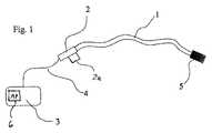
次に、図1及び2を参照すると、本発明の原理に基づいて構成された典型的な装置には、近位端2がケーブル4を介してコンソール3に結合された変形体1が含まれている。詳細に後述するように、変形体1には、例として、血管または器官の診断または治療を行う、既知のいくつかのエンド・エフェクタのうちの任意の1つ以上を備えた、遠位端5が含まれている。本発明の説明は、心臓マッピング及びアブレーション用のカテーテル・システムに関連して行われるが、もちろん、本発明に基づいて構成された医療装置は、上述の特許に記載のような、血管または器官に薬剤または生理活性剤を送達するとか、あるいは、経心筋血管形成術またはクライオ・アブレーションを実施するといった、他の目的に利用することも有利である。 Referring now to FIGS. 1 and 2, an exemplary device constructed in accordance with the principles of the present invention includes a
近位端2には、本明細書において後述する多次元力ベクトルの計算に利用可能なデータを記憶する、メモリ・チップ、RFIDタグ、または、バーコード・ラベルのような記憶装置2aを含むのが望ましい。あるいはまた、記憶装置2aは、近位端2に固定する必要はなく、代わりに、各変形体に個別に関連した、パッケージング部品(packaging)のような個別部品とすることが可能である。引張りワイヤまたは適切に構成された電気活性ポリマのような、それ自体既知のメカニズムを利用して、近位端2を手動または自動で操作し、遠位端5を所望の量だけ折り曲げるか、または、屈曲させることが可能である。変形体1は、手動または自動で、進行、逆行、及び、回転させることも可能である。
変形体1には、近くに延び、近位端2及びケーブル3を介してコンソール3に結合されている、遠位端5に配置された少なくとも2つの光ファイバ・センサが含まれている。変形体には、3つの光ファイバ・センサが配置されているのがより望ましい。さらに、遠位端5のエンド・エフェクタとやりとりされる制御信号は、ケーブル4の適合するコンポーネントを介してコンソール3に、すなわち、近位端2の触覚コンポーネントに伝送される。明らかなことだが、ケーブル4の性質は、変形体1の遠位端5に配置されたエンド・エフェクタの性質によって決まる。
コンソール3には、光ファイバ・センサを駆動し、その出力信号を解釈するための電子及び光学コンポーネントが含まれている。コンソール3には、さらに、変形体の遠位端に加えられる力によって、光ファイバ・センサに生じる波長変化に相当する出力信号を受信する、プログラムされた汎用マイクロプロセッサまたは特定用途向け集積回路のようなプロセシングロジック6が含まれている。プロセシングロジック6は、詳細に後述するように、その出力信号および、個々の変形体の物理的特性の行列に基づいて、多次元力ベクトルを計算する。コンソール3には、視覚表示装置または聴覚装置のような、負荷検知システムからの出力を表示する手段も含まれているのが望ましい。代替案として、コンソール3は、独立したモニタに表示する信号を出力することも可能である。 The
次に図2及び3を参照すると、変形体1には、その内部に少なくとも2つの光ファイバ・センサ7が配置されていて、変形体1の変形がセンサ7に伝達されるようになっているのが望ましい。変形体の中立軸の位置が分かっているか、あるいは、製造中に決定される限りにおいて、2つの光ファイバ・センサを用いることが可能である。変形体1は、少なくとも3つの光ファイバ・センサを組み込んでいて、一般に、ガイド・ワイヤまたはカテーテルの製造に用いられるような、成形、機械加工、または、押し出し加工を施された材料を含むのがより望ましい。光ファイバが変形体1の一体部分を形成することを確実にするため、接着剤または、例えば、オーバモールドまたは共押出しのような他の手段を利用して、光ファイバを変形体内に固定することが可能である。図3において、光ファイバ7は、接着剤8を用いて、変形体1内に接着されている。 Next, referring to FIGS. 2 and 3, at least two
3つの光ファイバ・センサが用いられる場合、光ファイバ7は、変形体1内に配置されるので、光ファイバ・センサは同一平面上にはない、すなわち、単一平面内に位置しないということになる。一例として、光ファイバは、カテーテルの縦軸を中心とする正三角形の頂点に配置される。光ファイバが、変形体1の変形中に、程度の異なる曲げ及び伸長を被る限りにおいて、他の構成も可能である。光ファイバ・センサ7は、ファイバ・ブラッグ・グレーティング(FBG)、長周期回折格子(LPG)、イントリンシック・ファブリ・ペロー干渉計(IFPT)、エキストリンシック・ファブリ・ペロー干渉計(EFPT)、2、3、または、4アームのマイケルソン干渉計(MI)、ブリュアン散乱歪みセンサまたは、強度に基づく光ファイバ歪みセンサの中から選択することが可能である。 If three fiber optic sensors are used, the
次に図4を参照すると、遠位端5にFBGまたはLPG歪みセンサ9が配置された3つの光ファイバ7を収容する変形体1が描かれている。FBGセンサは、安定したブラッグ回折格子がファイバのコアに施された(例えば、フォトエッチングされた)干渉計である。ファイバ・コアの屈折率の周期的変動領域は、所定のブラッグ波長を有する光を反射する極めて狭帯域の反射フィルタの働きをする。従って、光は、FBGから、中心波長がブラッグ波長及びコアの平均屈折率に線形的に従属する狭いスパイク状に反射される。その結果、格子特性を変化させる変形は、反射ブラッグ波長をシフトさせることになる。 Referring now to FIG. 4, a
LPGは、構造がFBGと似ており、周期がFBGよりもはるかに長い、ファイバ・コアの屈折率の周期的屈折率変調を生じる単一モード・ファイバ7を含む。FBGではなくLPGを用いる変形体の使用及び操作は、後述のものと同様である。 The LPG includes a
装置の使用中、変形体1の遠位端は、器官の組織に接触することによって加えられる負荷のために圧縮されて、曲がる。遠位端に位置する光ファイバ7の部分も変形するが、程度は遠位端におけるそれぞれの位置に応じてさまざまである。 During use of the device, the distal end of the
FBGセンサの初期較正、すなわち、加えられる力がない場合にブラッグ回折格子から反射される平均波長(「ブラッグ波長」と呼ばれる)は、光ファイバの製造中に施された格子の特性から決定される。ブラッグ波長からの偏差は、どれも歪みのような正確なパラメータと比例関係にある。図4の実施形態の場合、ブラッグ回折格子によれば、ブラッグ回折格子によって反射される光の波長変化を測定することによって、光ファイバ7のそれぞれの変形(伸長または収縮)を定量化することが可能になる。 The initial calibration of the FBG sensor, i.e. the average wavelength reflected from the Bragg grating in the absence of applied force (referred to as "Bragg wavelength") is determined from the characteristics of the grating applied during the manufacture of the optical fiber. . Any deviation from the Bragg wavelength is proportional to an exact parameter such as distortion. In the case of the embodiment of FIG. 4, according to the Bragg diffraction grating, it is possible to quantify each deformation (elongation or contraction) of the
変形体の既知の物理特性に加え、以上の情報によって、コンソール3のプロセシングロジック6は、適切なアルゴリズムを用いて多次元力ベクトルの成分を計算することが可能になる。その後、力ベクトルは、例えば、ディスプレイ・スクリーン上のグラフとして、あるいは、コンソール3に収容されているか、または、コンソール3に結合された聴覚装置から放出される音の高さを変化させることによって、表示することもできるし、別の方法で表わすことも可能である。 In addition to the known physical properties of the variant, the above information allows the
さらに図4に言及すると、光ファイバ7の1つは、他の光ファイバを越えて延び、変形体の前方端の温度を測定するための第2のFBG(またはLPG)を含んでいるのが望ましい。変形体の前方端における温度変化は、例えば、アブレーション電極の動作によって生じる可能性があり、関連するブラッグ波長を変化させることになる。ファイバの物理的特性を知り、回折格子によって反射される光の波長を測定することによって、プロセシングロジック6は、例えば、組織切除の進行を監視するため、遠位端のレベルにおける温度を計算することができる。 Still referring to FIG. 4, one of the
もう一度図1を参照すると、コンソール3には、ケーブル4を介して光ファイバに光ビームを注入するように構成された、波長可変レーザ・ダイオードが望ましいレーザと、歪みセンサ及び変形体に加えられる変形に起因する、反射光ビームの特性変動を検出する光検出器が含まれている。コンソール3には、ファイバ・ブラッグ・グレーティング復調器が含まれているのが望ましい。 Referring once again to FIG. 1, the
こうしたシステムの場合、光ファイバ・センサのそれぞれは、波長の異なる、従って、指定の周波数範囲内で応答する、ブラッグ回折格子を備えている。波長可変レーザは、光ファイバ・センサの全てに結合されて、毎秒数回ずつ、ある特定の周波数の走査を行う。レーザの周波数が、回折格子の周波数を中心とする場合、フォトダイオードは、各ブラッグ回折格子毎に波長変化を記録する。こうして、波長可変レーザが、センサの回折格子周波数の走査をくまなく実施するので、光ファイバ・センサのそれぞれを調べることが可能である。 In such a system, each of the fiber optic sensors includes a Bragg grating that has a different wavelength and thus responds within a specified frequency range. A tunable laser is coupled to all of the fiber optic sensors to scan at a particular frequency several times per second. When the frequency of the laser is centered on the frequency of the diffraction grating, the photodiode records the wavelength change for each Bragg diffraction grating. Thus, the tunable laser performs a full scan of the sensor's diffraction grating frequency so that each of the fiber optic sensors can be examined.
さらに本発明の原理によれば、プロセシングロジック6は、ブラッグのファイバ・グレーティング復調器の出力から2次元または3次元力ベクトルを計算するようにプログラムされる。次に、これらの計算の基礎となる理論について説明する。 Further in accordance with the principles of the present invention,
ポリエーテル・エーテル・ケトン(「PEEK」)を含む変形体内に3つのブラッグの光ファイバ歪みセンサが埋め込まれている装置の場合、全歪みは、下記の方程式を利用して計算することが可能である。
ここで、r−基準(ゼロ)測定値がセットされる時間
t−基準時間に関連した時間
λir,i=1,4−ブラッグ回折格子の基準波長
λit,i=1,4−時間tにおけるブラッグ回折格子の波長
εit,i=1,3−時間tにおける全歪み値
ΔTt−時間tにおける温度変化
Cε−波長と歪みとの間の線形性係数
Cεt−ブラッグ回折格子の温度補償係数
CT−波長と温度の間の線形性係数
λr−ブラッグ回折格子基準波長の行列(ベクトル)
λt−時間tにおけるブラッグ回折格子波長の行列(ベクトル)
εt−全歪みと温度変化の行列(ベクトル)
C−歪み変換及び補償行列For devices with three Bragg fiber optic strain sensors embedded in a variant containing polyether ether ketone ("PEEK"), the total strain can be calculated using the following equation: is there.
Where r-time when reference (zero) measurement is set t-time associated with reference time λir , i = 1,4-reference wavelength of Bragg grating λit , i = 1,4-time t Wavelength εit , i = 1,3−total strain value at time t ΔTt −temperature change at time t Cε−linearity coefficient between wavelength and strain Cεt −temperature of Bragg grating Compensation coefficient CT -Linearity coefficient between wavelength and temperature λr -Bragg grating reference wavelength matrix (vector)
λt -matrix of Bragg grating wavelengths at time t (vector)
εt -Total strain and temperature change matrix (vector)
C-distortion transformation and compensation matrix
全ての歪みには、変形体の測定温度と所定の基準温度との差から生じる変形体の熱膨張に起因する成分が含まれている。従って、加えられる力の関数である弾性歪みは、下記の方程式を用いて計算することが可能である。
ここで、εei,t,l=1,3−時間tにおける弾性歪み値
αT−カテーテル材料(PEEK)の熱膨張係数
εei,t−時間tにおける弾性歪みの行列(ベクトル)
αT−温度降下行列
(1.1a)∧(1.2a)⇒εei,t=αT・C・(λt−λr) (1.3)All strains include a component resulting from thermal expansion of the deformable body resulting from a difference between the measured temperature of the deformable body and a predetermined reference temperature. Accordingly, the elastic strain, which is a function of the applied force, can be calculated using the following equation:
Here, εei, t , l = 1,3-elastic strain value at time t αT−thermal expansion coefficient of catheter material (PEEK) εei, t −elastic strain matrix at time t (vector)
αT −Temperature drop matrix (1.1a) ∧ (1.2a) ⇒εei, t = αT・ C ・ (λt −λr ) (1.3)
弾性歪みは、変形体の物理的寸法と材料特性の両方の関数として、光ファイバ・センサが受ける内力に関連している。
ここで、x1及びy1、i=1,3−カテーテル断面の重心に関するブラッグ回折格子の座標
Eten−カテーテルの等価張力/圧縮ヤング率
Eflex−カテーテルの等価曲げヤング率
Ix−x軸に関する慣性モーメント
Iy−y軸に関する慣性モーメント
Nzt−時間tにおけるz軸方向の法線力
Mxt−時間tにおけるx軸に関する曲げモーメント
Myt−時間tにおけるy軸に関する曲げモーメント
G−形状寸法行列
δ−たわみ性行列
IF,t−時間tにおける内力の行列(ベクトル)Elastic strain is related to the internal force experienced by the fiber optic sensor as a function of both the physical dimensions of the deformation and the material properties.
Where x1 and y1 , i = 1,3-coordinates of the Bragg grating with respect to the center of gravity of the catheter cross section Eten -equivalent tension / compression Young's modulus of catheter Eflex -equivalent bending Young's modulus of catheter Ix -x axis Moment of inertia Iy −Moment of inertia abouty- axis Nzt −Normal force in z-axis direction at time t Mxt −Bending moment about x-axis at time t Myt −Bending moment about y-axis at time t G−Geometry Matrix δ-flexibility matrix IF, t- matrix of internal force at time t (vector)
方程式(2.1)は、弾性ひずみの関数として内力について解くように整理することが可能である。次に、方程式(1.3)からの弾性歪みを整理した行列系に代入して、下記の方程式(2.3)に示すように、弾性ひずみの関数として内力を計算することが可能である。
ここで、S=δ-1−剛性行列
(1.3)∧(2.1a)⇒lF,t=S・G-1・αT・C・(λt−λr) (2.3)Equation (2.1) can be arranged to solve for internal forces as a function of elastic strain. Next, it is possible to calculate the internal force as a function of the elastic strain as shown in the following equation (2.3) by substituting the elastic strain from the equation (1.3) into an organized matrix system. .
Where S = δ−1 −stiffness matrix (1.3) ∧ (2.1a) → lF, t = S · G−1 · αT · C · (λt −λr ) (2.3)
光ファイバ・センサによって生じる内力を、組織壁によって変形体の遠位端に実際に加えられる接触外力に関連づけることのみが残されている。これらの力は、変形体がほとんど圧縮できないものと仮定して、変形体の外壁からの光ファイバ・センサの位置に基づいて計算される。
ここで、Fx,t−x軸方向の時間tにおける接触横外力(逆向きの)
Fy,t−y軸方向の時間tにおける接触横外力(逆向きの)
Fz,t−z軸方向の時間tにおける接触法線外力(逆向きで、圧縮は正)
d−横方向の力の接触点とセンサを備えた断面との距離(z軸に沿った)
Ft−時間tにおける接触外力の行列
d−変換行列
(2.3)∧(3.1a)⇒Ft=d・S・G1・αT・C・(λt−λr) (3.2)
Ft=Kλ・(λt−λr)=Kλ・λt−Fr (3.3)
ここで、
Kλ−力変換行列、Kλ=d・S・G-1・αT・C (3.4)
Fr−基準力行列(ベクトル)、Fr=Kλ・λr (3.5)
方程式(3.1)〜方程式(3.5)を解くと、変形体の外面に加えられる法線力及び横方向の力、すなわち、Fnorm,t=Fz,t及びFtrans,t=平方根(F2x、t,t+F2y,t)が得られる。横方向の力を加える角度Ytは、表1から計算することが可能である。
Here, the contact lateral external force at the time t in the Fx, t −x direction (reverse direction)
Fy, t -Contact lateral force at time t in the y-axis direction (reverse direction)
Fz, t -Contact normal force at time t in the z-axis direction (reverse direction, compression is positive)
d—distance between lateral force contact point and cross section with sensor (along z-axis)
Ft-matrix of contact external force at time t d-transformation matrix (2.3) ∧ (3.1a) ⇒ Ft = d · S · G1 · αT · C · (λt- λr ) (3.2)
Ft = Kλ · (λt −λr ) = Kλ · λt −Fr (3.3)
here,
Kλ -force conversion matrix, Kλ = d ・ S ・ G−1・ αT・ C (3.4)
Fr −reference force matrix (vector), Fr = Kλ · λr (3.5)
Solving equations (3.1)-(3.5), normal and lateral forces applied to the outer surface of the deformable body, ie, Fnorm, t = Fz, t and Ftrans, t = The square root (F2x, t , t + F2y, t ) is obtained. The angle Yt at which the lateral force is applied can be calculated from Table 1.
方程式(1.1)〜(3.5)に用いられている値の多くは、変形体のブラッグ波長、熱膨張係数および、弾性率といった、変形体または光ファイバ・センサの材料特性に関連している。光ファイバ・センサと変形体の外面との間の距離といった他の値は、用いられる製造工程により変動する可能性がある。 Many of the values used in equations (1.1) to (3.5) are related to the material properties of the deformation or fiber optic sensor, such as the Bragg wavelength, thermal expansion coefficient, and modulus of elasticity of the deformation. ing. Other values such as the distance between the fiber optic sensor and the outer surface of the deformable body may vary depending on the manufacturing process used.
計算された力ベクトルの正確度を確保するため、各変形体に関する特定の情報は、記憶装置2aに記憶することが可能である。一般に、情報は、変形体を利用する前に、コンソール3に入力されるデータ・ファイルの形態をとる。例えば、記憶装置2aには、こうした情報が記憶される、ケーブル4に関連したメモリ・チップ、または、変形体の近位端2または変形体のパッケージングに配置されたバーコードまたはRFIDタグを含むことが可能である。代わりに、個々の変形体に固有のデータは、取り外し可能な記憶装置(例えば、CD)からまたは、メーカのウェブサイトからの安全なダウンロードを介して、コンソール3にアップロードすることが可能である。 In order to ensure the accuracy of the calculated force vector, specific information about each deformable body can be stored in the storage device 2a. In general, the information takes the form of a data file that is input to the
各変形体に固有の情報は、変形体を一連の既知の力にさらすことによって、変形体の製造中に実施される、較正ステップ中に得ることが可能である。この場合、上記方程式は成り立たない可能性があり、従って、法線力及び横方向の力は、力・波長変換行列から直接計算することが可能である。
F(t)=K(λ(t)−λ0) (4.0)
ここで、
F(t)は、力のベクトル[Fx,t,Fy,t,Fz,t]であり、
λ(t)は、個々のセンサについて測定された波長のベクトル[λ1,t,λ2,t,λ3,t]であり、
λ(0)は、加えられる力がゼロの場合に、個々のセンサについて測定された波長のベクトル[λ01,λ02,λ03]であり、
Kは、変形体が一連の既知の力を受けるときに計算された行列である。Information specific to each deformation can be obtained during a calibration step performed during manufacture of the deformation by exposing the deformation to a series of known forces. In this case, the above equation may not hold, so the normal and lateral forces can be calculated directly from the force-wavelength conversion matrix.
F (t) = K (λ (t) −λ0 ) (4.0)
here,
F (t) is a force vector [Fx, t , Fy, t , Fz, t ],
λ (t) is a vector of wavelengths [λ1, t , λ2, t , λ3, t ] measured for individual sensors,
λ (0) is a vector of wavelengths [λ01 , λ02 , λ03 ] measured for each sensor when the applied force is zero,
K is a matrix calculated when the deformation body receives a series of known forces.
製造の較正ステップ中、変形体は、次の力に順次さらされる、(1)既知の大きさの純粋に軸方向の力F′、(2)既知の大きさの横方向の力F″および、(3)力F″の方向に対し90度をなすように加えられる既知の大きさの横方向の力F″′。F′、F″、F″′および、波長の全てが既知の場合、力・歪み変換行列Kは、次のように計算することが可能である。
K=F(λ(t)−λ0)-1 (5.0)
または
K = F (λ (t) −λ0 )−1 (5.0)
Or
上述のように計算された法線力、横方向の力、及び、横方向の力を加える角度の値は、コンソール3の一部を形成するか、または、コンソール3に結合されたディスプレイ・モニタに、数値として出力することが可能である。さらに、可変サイズのまたは着色された矢印を含む図形を表示して、変形体の遠位端に加えられる横方向の力の大きさ及び方向を視覚化するため、円周上のある位置を指すことが可能である。この表示を監視することによって、オペレータは、変形体の遠位端に加えられる接触力に関するフィードバックを絶えず得ることができる。 The normal force, the lateral force, and the angle value for applying the lateral force calculated as described above form part of the
次に図5を参照して、光ファイバ歪みセンサ7にイントリンシック・ファブリ・ペロー干渉計(IFPI)が含まれた、別の実施形態について説明する。光ファイバの1つが、延び、遠位端の前方端の温度を測定するための第2のIFPIセンサ13を含んでいる。 Next, another embodiment in which the fiber
IFPIには、リフレクタ12が一方の端部に配置されて、光共振器11を形成している部分を備える、単一モード光ファイバが含まれている。リフレクタには、ファイバに形成された半反射鏡面を含むこともできるし、あるいはまた、2つのFBGを含むことも可能である。コンソール3に配置されたレーザ・ダイオードから放射される光は、近位リフレクタにぶつかって、特定の波長14で部分的に反射される。近位リフレクタを通過し、遠位リフレクタにぶつかる光も反射される。2つの反射ビームは、結果として、コンソール3に配置された光検出器によって検出される、干渉による強め合い及び弱め合いを生じることになる。 IFPI includes a single mode optical fiber that includes a portion with a
歪みまたは温度が変動すると、光共振器11及びセンサ13の光路長が変化し、光ファイバの相対的曲がりの計算を可能にする反射特性に影響する。この情報は、さらに、器官または血管の壁組織との接触によって遠位端5に加えられる力ベクトルの計算を可能にする。 As strain or temperature varies, the optical path lengths of the
図6には、変形体1に3つのエキストリンシック・ファブリ・ペロー干渉計(EFPI)が収容された、本発明の変形体のもう1つの別の実施形態が例示されている。光ファイバ・センサの1つは、他の光ファイバ・センサを越えて延び、遠位端の前方端の温度を測定するための第2のEFPIセンサ17を含んでいる。EFPIセンサには、光ファイバの中空毛細管15及び切断端16によって形成された光共振器11が含まれている。中空毛細管には空気が収容されている。EPFIの働きは、ファイバの切断端がレフレクタの働きをして、特定波長18を反射するという点を除くと、IFPIに関して上述のところと同様である。切断端16から反射された光は、干渉による強め合い及び弱め合いを生じる2つのビームになる。歪みまたは温度が変動すると、光共振器の光路長が変化し、反射特性に影響する。 FIG. 6 illustrates another alternative embodiment of the variant of the present invention in which
図7には、変形体1にマイケルソン干渉計を形成する3つの光ファイバ7が含まれる、本発明の変形体の更に別の実施形態が例示されている。各光ファイバ7には、その遠位端にリフレクタ19が含まれており、光ファイバは、近位端が光カプラ20によって結合されている。コンソール3に配置されたレーザ・ダイオードからファイバ21に波が送り込まれ、カプラ20によって、干渉計の光ファイバ([アーム])のそれぞれに分離される。カプラ20は、各アームから後方反射される光を結合する。干渉性または低干渉性の干渉計を利用して、異なるファイバから反射される光の相対位相の変動を測定して、変形体1が被る歪みが計算される。計算された歪みに基づいて、変形体の遠位端と器官または血管壁の組織との接触力を求めることが可能である。 FIG. 7 illustrates yet another embodiment of the variant of the present invention in which the
次に図8を参照して、光ファイバに高分解能ブリュアン・センサが含まれる実施形態について説明する。ブリュアン・センサは、光ファイバの固有現象である散乱22の原理を利用する。この現象は、光とファイバに存在する光子との相互作用(圧力波)から生じる。波23が後方に散乱し、光周波数が送り込まれた波に対してシフトする。光ファイバ7の1つが、他の光ファイバを越えて延び、遠位端の前方端における温度を測定するための第2のブリュアン散乱センサ24を含んでいる。歪みまたは温度が変動すると、光周波数がシフトする。衝撃、位相変調または、他の技法を利用して、ファイバに沿ったさまざまな位置26を選択し、これらの位置における歪み状態を測定することが可能である。 Next, an embodiment in which an optical fiber includes a high-resolution Brillouin sensor will be described with reference to FIG. The Brillouin sensor uses the principle of scattering 22 which is an inherent phenomenon of optical fibers. This phenomenon arises from the interaction (pressure wave) of light and photons present in the fiber. The
図9及び10を参照し、強度タイプの光ファイバ・センサを用いる、本発明のさらなる実施形態について説明する。すなわち、図9には、反射強度センサの利用が示され、一方、図10には、マイクロベンド強度センサの利用が示されている。 With reference to FIGS. 9 and 10, a further embodiment of the present invention using an intensity type fiber optic sensor will be described. That is, FIG. 9 shows the use of a reflection intensity sensor, while FIG. 10 shows the use of a microbend intensity sensor.
図9の場合、反射強度センサは、光ファイバ7内に接続ゾーン25を含んでいる。遠位端の変形によって生じる歪みまたは、温度変動の影響下において、接続ゾーン25は、透過および/または反射される光波26の振幅を変調する。反射光の強度変動は、それ自体既知の装置によって測定される。温度測定を実施するため、もう1つの光ファイバを設けることも可能である。 In the case of FIG. 9, the reflection intensity sensor includes a
図10の場合、マイクロベンド強度センサには、光ファイバ7の全長に沿って配置された接続ゾーン27が含まれている。接続ゾーン27は、ファイバにマイクロベンドを導入することによって得ることが可能である。遠位端の変形によって生じる歪みまたは、温度変動の影響下において、接続ゾーン27は、透過および/または反射される光波28の振幅を変調する。反射光の強度変動は、それ自体既知の装置によって測定される。 In the case of FIG. 10, the microbend intensity sensor includes a
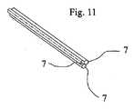
望ましい実施形態の1つによれば、3つの光ファイバは、互いに組み合わせて、図11に示すような一体部品を形成することもできるしあるいは、接着剤または他の適合する変形材料で埋め込んで、図12に示すような円筒形部品29を形成することも可能である。この構成によれば、図13に示すように、さらに別の従来の構造のカテーテルの管腔内に固定することが可能な、極めて小さい中実のアセンブリが得られ、同時に、光ファイバが破損から保護されることにもなる。本発明の原理によれば、図11〜13に示すようにファイバを束ねることによって、3つの光ファイバの全てが同一平面上に位置しないという保証が得られる。 According to one preferred embodiment, the three optical fibers can be combined together to form an integral part as shown in FIG. 11 or embedded with adhesive or other suitable deformation material, It is also possible to form a
次に、図4及び14を参照して、本発明の負荷検知能力を利用した典型的なアブレーション・カテーテルの遠位端について説明する。変形体1は、電極30、31、32を含んでおり、洗浄ポート34を備えた前方端33に結合されている。電極30、31、32、33は、例えば、腔内心電図、高周波切除等のような、カテーテルの特定用途の機能に応じて設けられる。前方端33は、電極とすることも可能である。カテーテルの遠位端の3次元位置確認を可能にするセンサ35を設けることも可能であり、センサ35は、電磁的、磁気的、電気的、超音波的原理に基づいている。 4 and 14, the distal end of a typical ablation catheter utilizing the load sensing capability of the present invention will now be described. The
変形体1には、上述のように構成された、少なくとも3つの光ファイバ・センサ9が含まれている。光ファイバの1つは、他の光ファイバを越えて延び、例えば、温度センサの働きをする第2のブラッグ回折格子10を含んでいる。ブラッグ回折格子10は、前方端33内に収容され、電極の動作から生じる前方端33の温度変化を計算するために利用可能である。洗浄ポート34は、カテーテル内に位置する1つ以上のチャネルと通じており、前方端電極の動作中、カテーテルの遠位端に、例えば、生理食塩水のような冷却液を送って、前方端の温度を低下させ、組織の切除を制御するために利用することが可能である。 The
前方端33は、例のため、高周波切除を施すように構成されているものとして説明されるが、レーザ、超音波、放射線、マイクロ波等のような、他の組織切除または治療用エンド・エフェクタを利用することも可能である。さらに、薬剤、幹細胞、または、他のタイプの細胞の注射器といった他の治療手段をカテーテルのヘッドに配置することも可能である。 The
図15に関連して、第4の光ファイバを利用して、他の光ファイバ歪みセンサの近くにおける変形体の温度が測定される、もう1つの代替実施形態について説明することにする。変形体1の材料は温度変動に反応しやすい可能性があるので、変形体の温度が変化すると、変形体及び埋め込まれた光ファイバが伸長または収縮する可能性がある。この影響によって、誤った力ベクトルの計算値を生じる可能性がある。従って、第4の光ファイバ7は、変形体の温度で誘発される伸長または収縮によって影響されず、従って、基準測定値をもたらすように、変形体1内にスライド可能に配置される。しかしながら、例えば、第4の光ファイバを利用することによって、センサ本体の温度が分かっている場合、力ベクトルの計算において、変形体の熱膨張または圧縮を補正することが可能である。 With reference to FIG. 15, another alternative embodiment will be described in which a fourth optical fiber is utilized to measure the temperature of the deformation body in the vicinity of another optical fiber strain sensor. Since the material of the
次に図16を参照して、本発明の負荷検知システムを利用した装置の別の実施形態について説明する。装置40には、遠位端42と近位端43がケーブル44を介してコンソール3に結合された変形体41が含まれている。コンポーネント41〜45の構造及び働きは、図1の実施形態に関して上述のものと同様である。 Next, another embodiment of the apparatus using the load detection system of the present invention will be described with reference to FIG. The device 40 includes a variant 41 having a distal end 42 and a proximal end 43 coupled to the
本発明の態様の1つによれば、図16の装置40には、さらに、コントローラ46、入力及び表示装置47および、アクチュエータ48を有するロボット制御システムも含まれている。アクチュエータ48は、プログラムされたマイクロプロセッサ46によって発生するコマンドに応答して変形体を操作するため、変形体41に結合されている。コントローラ46は、入力及び表示装置47を介して入力される命令によってプログラムされ、アクチュエータ48の動作は、その装置47の表示部分を介して監視することが可能である。コントローラ46は、本発明の負荷検知システムの出力を受信し、その情報を利用して、変形体41及びアクチュエータ48の操作を制御するため、コンソール45に結合されている。コンソール45は、いつ変形体41のエンド・エフェクタを操作するかを決定するために利用される、コントローラ46からの入力を受信することも可能である。 In accordance with one aspect of the present invention, the apparatus 40 of FIG. 16 further includes a robot control system having a controller 46, an input and display device 47, and an actuator 48. Actuator 48 is coupled to deformable body 41 for manipulating the deformable body in response to commands generated by programmed microprocessor 46. The controller 46 is programmed by input and commands entered via the display device 47 and the operation of the actuator 48 can be monitored via the display portion of the device 47. The controller 46 is coupled to the console 45 for receiving the output of the load sensing system of the present invention and using the information to control the operation of the deformable body 41 and the actuator 48. The console 45 can also receive input from the controller 46 that is utilized to determine when to operate the end effector of the deformable 41.
例えば、変形体41には、患者の心臓内における電位のマッピングを行うように設計された電気生理学的カテーテルを含むことが可能である。この場合、遠位端42には、図14に関連して本書で上述の一連のマッピング及びアブレーション電極を含むことが可能である。上述のように、患者の心臓内における電位をマッピングする既知の方法は、臨床医が、カテーテル・シャフトによる触覚フィードバックによって、または、インピーダンス測定を利用して、組織壁との係合を判定するので、時間のかかる作業になる。 For example, the deformable body 41 may include an electrophysiological catheter designed to perform potential mapping in the patient's heart. In this case, the distal end 42 can include a series of mapping and ablation electrodes as described herein above in connection with FIG. As noted above, known methods for mapping electrical potentials within a patient's heart allow clinicians to determine engagement with a tissue wall by tactile feedback via a catheter shaft or using impedance measurements. It ’s time consuming.
本発明の原理によれば、アクチュエータ48には、患者の心臓内でカテーテルを進め、回転させることが可能な多軸ツールが含まれる。コントローラ46は、遠位端42が受ける接触力が、コンソール45による監視を介して判定される所定の範囲内になるまで、カテーテルを操作するようにプログラムすることが可能である。接触力が所定の範囲内であると判定されると、電位を測定して、記録することが可能になる。次に、コントローラ46は、必要に応じてカテーテルの位置を直し、患者の心臓の他の所望の位置についてマッピングを行うことが可能である。 In accordance with the principles of the present invention, the actuator 48 includes a multi-axis tool that can advance and rotate the catheter within the patient's heart. The controller 46 can be programmed to operate the catheter until the contact force experienced by the distal end 42 is within a predetermined range determined through monitoring by the console 45. If it is determined that the contact force is within a predetermined range, the potential can be measured and recorded. The controller 46 can then reposition the catheter as necessary and map for other desired locations of the patient's heart.
遠位端によって加えられる接触力は、所望の範囲内に制御できるので、有利なことに組織を変形させるリスクが軽減される。従って、上述のような3次元位置確認システムが、カテーテル内に設けられている場合、測定点の測定値及び空間位置の正確な記録を得ることが可能である。本発明の負荷検知システムは、同様に、例えば、遠位端と組織壁との接触力が所定の最少値を超えるか、あるいは、所定の範囲内にある場合に限って、アブレーション電極に通電して、組織を切除することが可能な、図14に関して上述のアブレーション電極を含む治療システムに組み込むことが可能である。 The contact force applied by the distal end can be controlled within a desired range, advantageously reducing the risk of tissue deformation. Therefore, when the three-dimensional position confirmation system as described above is provided in the catheter, it is possible to obtain an accurate record of the measurement value of the measurement point and the spatial position. Similarly, the load detection system of the present invention applies power to the ablation electrode only when, for example, the contact force between the distal end and the tissue wall exceeds a predetermined minimum value or is within a predetermined range. Can be incorporated into a treatment system that includes the ablation electrode described above with respect to FIG.
さらに、変形体41の遠位端42が屈曲可能(articulable)である場合、コントローラ46は、コンソール45に、遠位端の屈曲度を調整する信号を送ることも可能である。こうして、本発明の負荷検知システムは、外部コントローラに対するフィードバック・ループの一部として機能するように構成できるだけではなく、それ自体、カテーテル41のエンド・エフェクタの操作を制御する外部制御信号を受信することも可能である。 Further, if the distal end 42 of the deformable body 41 is articulable, the controller 46 may send a signal to the console 45 that adjusts the degree of bending of the distal end. Thus, the load sensing system of the present invention can not only be configured to function as part of a feedback loop to an external controller, but itself receives external control signals that control the operation of the end effector of the catheter 41. Is also possible.
要するに、光ファイバ歪みセンサを利用すると、変形体の遠位端と器官または血管の壁組織との接触中に生じる多次元力ベクトルの計算が可能になる。こうした情報と3D位置決めセンサを組み合わせると、正確なマッピングが得られて加える力を最適にして、組織の診断または治療を施すことが可能になる。光ファイバ歪みセンサのサイズが小さく、これらの装置によって得られる測定値の分解能が高いので、湿度が高く、電磁妨害を受ける環境においても、極めて正確な測定値を得ることが可能になる。 In short, the use of a fiber optic strain sensor allows the calculation of multidimensional force vectors that occur during contact between the distal end of the deformable body and the organ or vessel wall tissue. Combining this information with a 3D positioning sensor can provide an accurate mapping and optimize the applied force for tissue diagnosis or treatment. Since the size of the optical fiber strain sensor is small and the resolution of the measurement values obtained by these devices is high, extremely accurate measurement values can be obtained even in an environment with high humidity and electromagnetic interference.
本発明の望ましい例となる実施形態について上述したが、当業者には明らかなように、本発明から逸脱することなく、さまざまな変更及び修正を加えることが可能である。特許請求の範囲は、本発明の真の精神及び範囲内に含まれるこうした全ての変更及び修正を網羅することを意図したものである。 While preferred exemplary embodiments of the present invention have been described above, it will be apparent to those skilled in the art that various changes and modifications can be made without departing from the invention. The claims are intended to cover all such changes and modifications as fall within the true spirit and scope of the invention.
Claims (38)
Translated fromJapanese前記装置は、遠位端を備える変形体と、
前記遠位端内に固定された少なくとも2つの光ファイバ・センサと、
前記光ファイバ・センサの出力を受信して作動可能なように結合されるプロセシングロジックと、を有し、
前記プロセシングロジックは、前記遠位端と前記器官または血管の組織壁との接触力に対応する多次元力ベクトルを計算するようにプログラムされた、
装置。A device for diagnosis or treatment of blood vessels or organs,
The device comprises a variant comprising a distal end;
At least two fiber optic sensors secured within the distal end;
Receiving and outputting the output of the fiber optic sensor, and processing logic coupled operatively;
The processing logic is programmed to calculate a multidimensional force vector corresponding to the contact force between the distal end and the tissue wall of the organ or blood vessel.
apparatus.
前記装置は、近位端と遠位端を備え、前記遠位端に変形材料が含まれる細長い本体と、
前記細長い本体を通って延び、同一平面上に存在しないように、前記遠位端内に固定された3つの光ファイバと、
前記遠位端内に配置され、前記3つの光ファイバそれぞれに結合された少なくとも1つの光歪みセンサと、
前記細長い本体に結合された記憶装置と、を含み、
前記記憶装置は、前記遠位端と前記器官または血管の組織壁との接触力に対応する3次元力ベクトルの計算を可能にする力・歪み変換行列を含んでいる、装置。A device for diagnosis or treatment of blood vessels or organs,
The device comprises an elongate body comprising a proximal end and a distal end, the distal end including a deformable material;
Three optical fibers extending through the elongate body and secured within the distal end such that they are not coplanar;
At least one optical strain sensor disposed within the distal end and coupled to each of the three optical fibers;
A storage device coupled to the elongate body;
The storage device includes a force-strain transformation matrix that allows calculation of a three-dimensional force vector corresponding to the contact force between the distal end and the tissue wall of the organ or vessel.
Applications Claiming Priority (3)
| Application Number | Priority Date | Filing Date | Title |
|---|---|---|---|
| EP05004852 | 2005-03-04 | ||
| EP05004852.9 | 2005-03-04 | ||
| PCT/IB2006/000428WO2006092707A1 (en) | 2005-03-04 | 2006-03-01 | Medical apparatus system having optical fiber load sensing capability |
Publications (2)
| Publication Number | Publication Date |
|---|---|
| JP2008531170Atrue JP2008531170A (en) | 2008-08-14 |
| JP5270174B2 JP5270174B2 (en) | 2013-08-21 |
Family
ID=34934077
Family Applications (1)
| Application Number | Title | Priority Date | Filing Date |
|---|---|---|---|
| JP2007557615AActiveJP5270174B2 (en) | 2005-03-04 | 2006-03-01 | Medical device system with optical fiber load detection capability |
Country Status (5)
| Country | Link |
|---|---|
| US (1) | US8182433B2 (en) |
| EP (1) | EP1858401A1 (en) |
| JP (1) | JP5270174B2 (en) |
| CN (2) | CN101132730B (en) |
| WO (1) | WO2006092707A1 (en) |
Cited By (19)
| Publication number | Priority date | Publication date | Assignee | Title |
|---|---|---|---|---|
| JP2011120906A (en)* | 2009-12-08 | 2011-06-23 | Biosense Webster (Israel) Ltd | Probe data mapping using contact information |
| WO2011114653A1 (en) | 2010-03-15 | 2011-09-22 | ソニー株式会社 | Evaluation device and evaluation method |
| WO2011114651A1 (en) | 2010-03-15 | 2011-09-22 | ソニー株式会社 | Calculation device and calculation method |
| WO2011114652A1 (en) | 2010-03-15 | 2011-09-22 | ソニー株式会社 | Determination device and determination method |
| JP2011255184A (en)* | 2010-06-10 | 2011-12-22 | Biosense Webster (Israel) Ltd | Weight-based calibration system for pressure sensitive catheter |
| JP2012120843A (en)* | 2010-12-09 | 2012-06-28 | Biosense Webster (Israel) Ltd | Identifying critical cfae site using contact measurement |
| JP2012514514A (en)* | 2009-01-09 | 2012-06-28 | エンドーセンス エスアー | Fiber optic force sensing catheter |
| WO2012098623A1 (en) | 2011-01-19 | 2012-07-26 | ソニー株式会社 | Laser therapy apparatus, laser therapy system and assessment method |
| JP2013505441A (en)* | 2009-09-18 | 2013-02-14 | ルナ イノベーションズ インコーポレイテッド | Optical position and / or shape sensing |
| JP2013518656A (en)* | 2010-02-09 | 2013-05-23 | コーニンクレッカ フィリップス エレクトロニクス エヌ ヴィ | Apparatus, system and method for imaging and treatment using optical position sensing |
| JP2013538090A (en)* | 2010-08-23 | 2013-10-10 | コーニンクレッカ フィリップス エヌ ヴェ | Mapping system and method for medical procedures |
| JP2014517740A (en)* | 2011-04-14 | 2014-07-24 | エンドーセンス エスアー | Small force sensor for catheter |
| JP2015524330A (en)* | 2012-08-09 | 2015-08-24 | コーニンクレッカ フィリップス エヌ ヴェ | Patient interface customization or adjustment |
| JP2017534837A (en)* | 2014-09-08 | 2017-11-24 | コーニンクレッカ フィリップス エヌ ヴェKoninklijke Philips N.V. | Detection of surface contact by optical shape detection |
| JP2017213444A (en)* | 2013-05-08 | 2017-12-07 | ボストン サイエンティフィック サイムド,インコーポレイテッドBoston Scientific Scimed,Inc. | Medical systems and devices for temperature monitoring and control during ablation procedure |
| JP2017537666A (en)* | 2014-09-30 | 2017-12-21 | コーニンクレッカ フィリップス エヌ ヴェKoninklijke Philips N.V. | Trigger using optical shape sensing fiber |
| JP2020513269A (en)* | 2016-12-09 | 2020-05-14 | インテュイティブ サージカル オペレーションズ, インコーポレイテッド | System and method for body tissue heat flux distribution sensing |
| JP2022549203A (en)* | 2019-09-20 | 2022-11-24 | ロビューテ | Apparatus for propulsion and steering of microstructures |
| JP2025020005A (en)* | 2023-07-28 | 2025-02-07 | キストラー ホールディング アクチエンゲゼルシャフト | Optical fiber system for determining at least one physical parameter and method for determining at least one physical parameter using an optical fiber system - Patents.com |
Families Citing this family (206)
| Publication number | Priority date | Publication date | Assignee | Title |
|---|---|---|---|---|
| US7713190B2 (en) | 1998-02-24 | 2010-05-11 | Hansen Medical, Inc. | Flexible instrument |
| US6626899B2 (en) | 1999-06-25 | 2003-09-30 | Nidus Medical, Llc | Apparatus and methods for treating tissue |
| US7766894B2 (en) | 2001-02-15 | 2010-08-03 | Hansen Medical, Inc. | Coaxial catheter system |
| AU2003279097A1 (en)* | 2002-09-30 | 2004-04-19 | Vanderbilt University | Optical apparatus for guided liver tumor treatment and methods |
| US8007511B2 (en) | 2003-06-06 | 2011-08-30 | Hansen Medical, Inc. | Surgical instrument design |
| WO2005087128A1 (en) | 2004-03-05 | 2005-09-22 | Hansen Medical, Inc. | Robotic catheter system |
| US7976539B2 (en) | 2004-03-05 | 2011-07-12 | Hansen Medical, Inc. | System and method for denaturing and fixing collagenous tissue |
| US8075498B2 (en) | 2005-03-04 | 2011-12-13 | Endosense Sa | Medical apparatus system having optical fiber load sensing capability |
| US8496647B2 (en) | 2007-12-18 | 2013-07-30 | Intuitive Surgical Operations, Inc. | Ribbed force sensor |
| JP2009500086A (en) | 2005-07-01 | 2009-01-08 | ハンセン メディカル,インク. | Robotic guide catheter system |
| EP2363073B1 (en) | 2005-08-01 | 2015-10-07 | St. Jude Medical Luxembourg Holding S.à.r.l. | Medical apparatus system having optical fiber load sensing capability |
| US9254163B2 (en) | 2005-12-06 | 2016-02-09 | St. Jude Medical, Atrial Fibrillation Division, Inc. | Assessment of electrode coupling for tissue ablation |
| US10362959B2 (en) | 2005-12-06 | 2019-07-30 | St. Jude Medical, Atrial Fibrillation Division, Inc. | System and method for assessing the proximity of an electrode to tissue in a body |
| US8403925B2 (en) | 2006-12-06 | 2013-03-26 | St. Jude Medical, Atrial Fibrillation Division, Inc. | System and method for assessing lesions in tissue |
| US8603084B2 (en)* | 2005-12-06 | 2013-12-10 | St. Jude Medical, Atrial Fibrillation Division, Inc. | System and method for assessing the formation of a lesion in tissue |
| US9492226B2 (en) | 2005-12-06 | 2016-11-15 | St. Jude Medical, Atrial Fibrillation Division, Inc. | Graphical user interface for real-time RF lesion depth display |
| BRPI0621017A2 (en) | 2005-12-06 | 2011-11-29 | St Jude Medical Atrial Fibrill Div | tissue ablation electrode junction evaluation |
| US8406866B2 (en) | 2005-12-06 | 2013-03-26 | St. Jude Medical, Atrial Fibrillation Division, Inc. | System and method for assessing coupling between an electrode and tissue |
| US9962066B2 (en) | 2005-12-30 | 2018-05-08 | Intuitive Surgical Operations, Inc. | Methods and apparatus to shape flexible entry guides for minimally invasive surgery |
| US7930065B2 (en) | 2005-12-30 | 2011-04-19 | Intuitive Surgical Operations, Inc. | Robotic surgery system including position sensors using fiber bragg gratings |
| US8989528B2 (en) | 2006-02-22 | 2015-03-24 | Hansen Medical, Inc. | Optical fiber grating sensors and methods of manufacture |
| JP5631585B2 (en)* | 2006-03-22 | 2014-11-26 | コーニンクレッカ フィリップス エレクトロニクス エヌ.ヴィ. | Optical fiber equipment sensing system |
| US8048063B2 (en) | 2006-06-09 | 2011-11-01 | Endosense Sa | Catheter having tri-axial force sensor |
| KR101477133B1 (en) | 2006-06-13 | 2014-12-29 | 인튜어티브 서지컬 인코포레이티드 | Minimally invasive surgical system |
| WO2008011663A1 (en)* | 2006-07-26 | 2008-01-31 | Commonwealth Scientific And Industrial Research Organisation | An apparatus for pressure sensing |
| JP5148092B2 (en)* | 2006-09-11 | 2013-02-20 | オリンパスメディカルシステムズ株式会社 | Energy surgical device |
| US7941213B2 (en)* | 2006-12-28 | 2011-05-10 | Medtronic, Inc. | System and method to evaluate electrode position and spacing |
| US7894871B2 (en)* | 2006-12-29 | 2011-02-22 | St. Jude Medical, Atrial Fibrillation Division, Inc. | Filtering method for surface modeling |
| US8372021B2 (en)* | 2007-01-05 | 2013-02-12 | Merit Medical Systems, Inc. | Measuring and testing device for retractable medical devices |
| US20090036900A1 (en)* | 2007-02-02 | 2009-02-05 | Hansen Medical, Inc. | Surgery methods using a robotic instrument system |
| EP2122318A2 (en) | 2007-03-07 | 2009-11-25 | Koninklijke Philips Electronics N.V. | Medical apparatus with a sensor for detecting a force |
| CN101711125B (en) | 2007-04-18 | 2016-03-16 | 美敦力公司 | Long-term implantable active fixed medical electronic leads for non-fluoroscopy implants |
| WO2008131303A2 (en) | 2007-04-20 | 2008-10-30 | Hansen Medical, Inc. | Optical fiber shape sensing systems |
| US8157789B2 (en) | 2007-05-24 | 2012-04-17 | Endosense Sa | Touch sensing catheter |
| US8622935B1 (en) | 2007-05-25 | 2014-01-07 | Endosense Sa | Elongated surgical manipulator with body position and distal force sensing |
| US9096033B2 (en) | 2007-06-13 | 2015-08-04 | Intuitive Surgical Operations, Inc. | Surgical system instrument sterile adapter |
| EP2626030A3 (en) | 2007-08-14 | 2017-03-08 | Koninklijke Philips N.V. | Robotic instrument systems and methods utilizing optical fiber sensors |
| US8535308B2 (en) | 2007-10-08 | 2013-09-17 | Biosense Webster (Israel), Ltd. | High-sensitivity pressure-sensing probe |
| US8357152B2 (en)* | 2007-10-08 | 2013-01-22 | Biosense Webster (Israel), Ltd. | Catheter with pressure sensing |
| WO2009073913A1 (en)* | 2007-12-11 | 2009-06-18 | Commonwealth Scientific And Industrial Research Organisation | An apparatus for sensing a motion |
| JP5171535B2 (en)* | 2007-12-14 | 2013-03-27 | Ntn株式会社 | Load detection device and load detection method |
| US8561473B2 (en)* | 2007-12-18 | 2013-10-22 | Intuitive Surgical Operations, Inc. | Force sensor temperature compensation |
| US8290578B2 (en) | 2007-12-28 | 2012-10-16 | St. Jude Medical, Atrial Fibrillation Division, Inc. | Method and apparatus for complex impedance compensation |
| US9204927B2 (en) | 2009-05-13 | 2015-12-08 | St. Jude Medical, Atrial Fibrillation Division, Inc. | System and method for presenting information representative of lesion formation in tissue during an ablation procedure |
| JP5397965B2 (en)* | 2008-03-19 | 2014-01-22 | センソプティック エスエイ | Optical measuring element with unitary structure |
| US8260395B2 (en) | 2008-04-18 | 2012-09-04 | Medtronic, Inc. | Method and apparatus for mapping a structure |
| US8532734B2 (en) | 2008-04-18 | 2013-09-10 | Regents Of The University Of Minnesota | Method and apparatus for mapping a structure |
| US8663120B2 (en) | 2008-04-18 | 2014-03-04 | Regents Of The University Of Minnesota | Method and apparatus for mapping a structure |
| US8494608B2 (en) | 2008-04-18 | 2013-07-23 | Medtronic, Inc. | Method and apparatus for mapping a structure |
| US8340751B2 (en)* | 2008-04-18 | 2012-12-25 | Medtronic, Inc. | Method and apparatus for determining tracking a virtual point defined relative to a tracked member |
| US8839798B2 (en) | 2008-04-18 | 2014-09-23 | Medtronic, Inc. | System and method for determining sheath location |
| WO2009136311A2 (en)* | 2008-05-08 | 2009-11-12 | Koninklijke Philips Electronics N.V. | Contact pressure control for probe for material analysis |
| US8298227B2 (en) | 2008-05-14 | 2012-10-30 | Endosense Sa | Temperature compensated strain sensing catheter |
| EP2127604A1 (en)* | 2008-05-30 | 2009-12-02 | Nederlandse Organisatie voor toegepast- natuurwetenschappelijk onderzoek TNO | An instrument for minimally invasive surgery |
| US8437832B2 (en) | 2008-06-06 | 2013-05-07 | Biosense Webster, Inc. | Catheter with bendable tip |
| US20100030312A1 (en)* | 2008-07-31 | 2010-02-04 | Xiaonan Shen | Method and apparatus for lead length determination |
| US20100030063A1 (en)* | 2008-07-31 | 2010-02-04 | Medtronic, Inc. | System and method for tracking an instrument |
| GB0814533D0 (en)* | 2008-08-08 | 2008-09-17 | Ntnu Technology Transfer As | Measurement of bio-signals |
| US9101734B2 (en) | 2008-09-09 | 2015-08-11 | Biosense Webster, Inc. | Force-sensing catheter with bonded center strut |
| US8175681B2 (en) | 2008-12-16 | 2012-05-08 | Medtronic Navigation Inc. | Combination of electromagnetic and electropotential localization |
| US9326700B2 (en)* | 2008-12-23 | 2016-05-03 | Biosense Webster (Israel) Ltd. | Catheter display showing tip angle and pressure |
| US9629678B2 (en)* | 2008-12-30 | 2017-04-25 | St. Jude Medical, Atrial Fibrillation Division, Inc. | Controlled irrigated catheter ablation systems and methods thereof |
| US8600472B2 (en) | 2008-12-30 | 2013-12-03 | Biosense Webster (Israel), Ltd. | Dual-purpose lasso catheter with irrigation using circumferentially arranged ring bump electrodes |
| US8475450B2 (en) | 2008-12-30 | 2013-07-02 | Biosense Webster, Inc. | Dual-purpose lasso catheter with irrigation |
| US8405822B2 (en) | 2009-04-22 | 2013-03-26 | Hottinger Baldwin Messtechnik Gmbh | Optical strain gauge comprising a fiber Bragg grating |
| DE102009018300A1 (en)* | 2009-04-22 | 2010-10-28 | Hottinger Baldwin Messtechnik Gmbh | Optical strain gauge |
| US9254123B2 (en) | 2009-04-29 | 2016-02-09 | Hansen Medical, Inc. | Flexible and steerable elongate instruments with shape control and support elements |
| US9393068B1 (en) | 2009-05-08 | 2016-07-19 | St. Jude Medical International Holding S.À R.L. | Method for predicting the probability of steam pop in RF ablation therapy |
| CA2703347C (en) | 2009-05-08 | 2016-10-04 | Endosense Sa | Method and apparatus for controlling lesion size in catheter-based ablation treatment |
| WO2010140069A1 (en) | 2009-06-04 | 2010-12-09 | Koninklijke Philips Electronics N.V. | Visualization apparatus |
| US8780339B2 (en) | 2009-07-15 | 2014-07-15 | Koninklijke Philips N.V. | Fiber shape sensing systems and methods |
| US8494613B2 (en) | 2009-08-31 | 2013-07-23 | Medtronic, Inc. | Combination localization system |
| US8494614B2 (en) | 2009-08-31 | 2013-07-23 | Regents Of The University Of Minnesota | Combination localization system |
| US8355774B2 (en) | 2009-10-30 | 2013-01-15 | Medtronic, Inc. | System and method to evaluate electrode position and spacing |
| US10688278B2 (en) | 2009-11-30 | 2020-06-23 | Biosense Webster (Israel), Ltd. | Catheter with pressure measuring tip |
| US8920415B2 (en) | 2009-12-16 | 2014-12-30 | Biosense Webster (Israel) Ltd. | Catheter with helical electrode |
| DE102009058607A1 (en)* | 2009-12-17 | 2011-06-22 | KUKA Laboratories GmbH, 86165 | Method and device for controlling a manipulator |
| US8521462B2 (en) | 2009-12-23 | 2013-08-27 | Biosense Webster (Israel), Ltd. | Calibration system for a pressure-sensitive catheter |
| US8529476B2 (en) | 2009-12-28 | 2013-09-10 | Biosense Webster (Israel), Ltd. | Catheter with strain gauge sensor |
| US8608735B2 (en) | 2009-12-30 | 2013-12-17 | Biosense Webster (Israel) Ltd. | Catheter with arcuate end section |
| US8374670B2 (en) | 2010-01-22 | 2013-02-12 | Biosense Webster, Inc. | Catheter having a force sensing distal tip |
| JP5515875B2 (en)* | 2010-03-08 | 2014-06-11 | セイコーエプソン株式会社 | Fall detection device, fall detection method |
| US8906013B2 (en) | 2010-04-09 | 2014-12-09 | Endosense Sa | Control handle for a contact force ablation catheter |
| US20110313280A1 (en)* | 2010-06-16 | 2011-12-22 | Assaf Govari | Optical contact sensing in medical probes |
| US11490957B2 (en) | 2010-06-16 | 2022-11-08 | Biosense Webster (Israel) Ltd. | Spectral sensing of ablation |
| US10314650B2 (en) | 2010-06-16 | 2019-06-11 | Biosense Webster (Israel) Ltd. | Spectral sensing of ablation |
| US8226580B2 (en) | 2010-06-30 | 2012-07-24 | Biosense Webster (Israel), Ltd. | Pressure sensing for a multi-arm catheter |
| KR101841067B1 (en)* | 2010-07-20 | 2018-03-22 | 더 존스 홉킨스 유니버시티 | Interferometric force sensor for surgical instruments |
| US8380276B2 (en) | 2010-08-16 | 2013-02-19 | Biosense Webster, Inc. | Catheter with thin film pressure sensing distal tip |
| BR112013004528A2 (en)* | 2010-09-01 | 2016-06-07 | Koninkl Philips Electronics Nv | optical guidewire system and method for advancing a catheter to a target region relative to a distal end of an optical guidewire |
| US20120071752A1 (en) | 2010-09-17 | 2012-03-22 | Sewell Christopher M | User interface and method for operating a robotic medical system |
| US8731859B2 (en) | 2010-10-07 | 2014-05-20 | Biosense Webster (Israel) Ltd. | Calibration system for a force-sensing catheter |
| US20130220032A1 (en) | 2010-10-26 | 2013-08-29 | Muthukumaran Packirisamy | System For Sensing a Mechanical Property of a Sample |
| US8979772B2 (en)* | 2010-11-03 | 2015-03-17 | Biosense Webster (Israel), Ltd. | Zero-drift detection and correction in contact force measurements |
| US10070793B2 (en)* | 2010-11-27 | 2018-09-11 | Securus Medical Group, Inc. | Ablation and temperature measurement devices |
| US9211094B2 (en)* | 2010-12-10 | 2015-12-15 | Biosense Webster (Israel), Ltd. | System and method for detection of metal disturbance based on contact force measurement |
| US9044244B2 (en) | 2010-12-10 | 2015-06-02 | Biosense Webster (Israel), Ltd. | System and method for detection of metal disturbance based on mutual inductance measurement |
| US10307205B2 (en) | 2010-12-10 | 2019-06-04 | Biosense Webster (Israel) Ltd. | System and method for detection of metal disturbance based on orthogonal field components |
| EP3482708B1 (en) | 2010-12-27 | 2021-03-10 | St. Jude Medical International Holding S.à r.l. | Prediction of atrial wall electrical reconnection based on contact force measured duing rf ablation |
| US9149327B2 (en) | 2010-12-27 | 2015-10-06 | St. Jude Medical Luxembourg Holding S.À.R.L. | Prediction of atrial wall electrical reconnection based on contact force measured during RF ablation |
| US9002442B2 (en) | 2011-01-13 | 2015-04-07 | Rhythmia Medical, Inc. | Beat alignment and selection for cardiac mapping |
| US9277872B2 (en) | 2011-01-13 | 2016-03-08 | Rhythmia Medical, Inc. | Electroanatomical mapping |
| US20120191079A1 (en) | 2011-01-20 | 2012-07-26 | Hansen Medical, Inc. | System and method for endoluminal and translumenal therapy |
| US20130310645A1 (en)* | 2011-01-28 | 2013-11-21 | Koninklijke Philips N.V. | Optical sensing for relative tracking of endoscopes |
| US9534965B2 (en)* | 2011-04-26 | 2017-01-03 | University Of New Brunswick | Flexible fibre optic deformation sensor system and method |
| CN102274015A (en)* | 2011-05-06 | 2011-12-14 | 天津大学 | Method and device for wrist strap type pulse signal extraction based on optical fiber vibration period analysis |
| US9510786B2 (en)* | 2011-06-22 | 2016-12-06 | Biosense Webster (Israel) Ltd. | Optical pressure measurement |
| US9220433B2 (en) | 2011-06-30 | 2015-12-29 | Biosense Webster (Israel), Ltd. | Catheter with variable arcuate distal section |
| CN102334984B (en)* | 2011-07-20 | 2013-01-02 | 上海波汇通信科技有限公司 | Intelligent chair used for measuring human physiology parameters |
| WO2013016640A2 (en)* | 2011-07-27 | 2013-01-31 | Zoll Medical Corporation | Method and apparatus for monitoring manual chest compression efficiency during cpr |
| US20130030363A1 (en) | 2011-07-29 | 2013-01-31 | Hansen Medical, Inc. | Systems and methods utilizing shape sensing fibers |
| US9662169B2 (en) | 2011-07-30 | 2017-05-30 | Biosense Webster (Israel) Ltd. | Catheter with flow balancing valve |
| EP2742321A1 (en)* | 2011-09-02 | 2014-06-18 | Koninklijke Philips N.V. | Rapid dense point cloud imaging using probabilistic voxel maps |
| JP6441679B2 (en) | 2011-12-09 | 2018-12-19 | メタベンション インコーポレイテッド | Therapeutic neuromodulation of the liver system |
| KR101310012B1 (en)* | 2011-12-19 | 2013-09-24 | 성균관대학교산학협력단 | Hybrid type multi-axis sensor |
| US9687289B2 (en) | 2012-01-04 | 2017-06-27 | Biosense Webster (Israel) Ltd. | Contact assessment based on phase measurement |
| EP2626680B1 (en)* | 2012-02-07 | 2015-10-07 | Sensoptic SA | Optical force sensing element and microsurgical instrument |
| US10881459B2 (en) | 2012-07-18 | 2021-01-05 | Bernard Boon Chye Lim | Apparatus and method for assessing tissue treatment |
| US10499984B2 (en) | 2012-07-18 | 2019-12-10 | Bernard Boon Chye Lim | Apparatus and method for assessing tissue treatment |
| US9526426B1 (en) | 2012-07-18 | 2016-12-27 | Bernard Boon Chye Lim | Apparatus and method for assessing tissue composition |
| US20140148673A1 (en) | 2012-11-28 | 2014-05-29 | Hansen Medical, Inc. | Method of anchoring pullwire directly articulatable region in catheter |
| US20140277334A1 (en) | 2013-03-14 | 2014-09-18 | Hansen Medical, Inc. | Active drives for robotic catheter manipulators |
| US9326822B2 (en) | 2013-03-14 | 2016-05-03 | Hansen Medical, Inc. | Active drives for robotic catheter manipulators |
| US9408669B2 (en) | 2013-03-15 | 2016-08-09 | Hansen Medical, Inc. | Active drive mechanism with finite range of motion |
| US20140276936A1 (en) | 2013-03-15 | 2014-09-18 | Hansen Medical, Inc. | Active drive mechanism for simultaneous rotation and translation |
| US9174024B1 (en) | 2013-03-15 | 2015-11-03 | St. Jude Medical Luxembourg Holdings S.À.R.L. | Steering control mechanisms for catheters |
| US9095682B2 (en) | 2013-04-30 | 2015-08-04 | St. Jude Medical Luxembourg Holding S.À.R.L. | Control handles for catheters |
| AU2014274903B2 (en) | 2013-06-05 | 2019-03-07 | Medtronic Ireland Manufacturing Unlimited Company | Modulation of targeted nerve fibers |
| EP3243476B1 (en) | 2014-03-24 | 2019-11-06 | Auris Health, Inc. | Systems and devices for catheter driving instinctiveness |
| US10046140B2 (en) | 2014-04-21 | 2018-08-14 | Hansen Medical, Inc. | Devices, systems, and methods for controlling active drive systems |
| EP3200718A4 (en) | 2014-09-30 | 2018-04-25 | Auris Surgical Robotics, Inc | Configurable robotic surgical system with virtual rail and flexible endoscope |
| US10314463B2 (en) | 2014-10-24 | 2019-06-11 | Auris Health, Inc. | Automated endoscope calibration |
| CA2969129A1 (en) | 2014-12-03 | 2016-06-09 | Metavention, Inc. | Systems and methods for modulating nerves or other tissue |
| CN104739389B (en)* | 2015-04-15 | 2017-04-26 | 中国人民解放军国防科学技术大学 | Curved surface strain gauge, pulse signal extraction device and method and pulse condition diagnosis and treatment system |
| WO2017053921A1 (en) | 2015-09-26 | 2017-03-30 | Boston Scientific Scimed Inc. | Intracardiac egm signals for beat matching and acceptance |
| CN105343984A (en)* | 2015-10-14 | 2016-02-24 | 乐普(北京)医疗器械股份有限公司 | Guide wire |
| CN106859762B (en)* | 2015-12-11 | 2020-01-24 | 上海微创电生理医疗科技有限公司 | Electrophysiology catheter |
| US11445937B2 (en)* | 2016-01-07 | 2022-09-20 | St. Jude Medical International Holding S.À R.L. | Medical device with multi-core fiber for optical sensing |
| CN109069840B (en) | 2016-02-04 | 2022-03-15 | 心脏起搏器股份公司 | Delivery system with force sensor for leadless cardiac devices |
| US11478150B2 (en)* | 2016-03-28 | 2022-10-25 | Becton, Dickinson And Company | Optical fiber sensor |
| US10524859B2 (en) | 2016-06-07 | 2020-01-07 | Metavention, Inc. | Therapeutic tissue modulation devices and methods |
| EP4335363A3 (en) | 2016-07-08 | 2024-04-17 | Intuitive Surgical Operations, Inc. | Calculation of redundant bend in multi-core fiber for safety |
| US10463439B2 (en) | 2016-08-26 | 2019-11-05 | Auris Health, Inc. | Steerable catheter with shaft load distributions |
| US11241559B2 (en) | 2016-08-29 | 2022-02-08 | Auris Health, Inc. | Active drive for guidewire manipulation |
| US9931025B1 (en)* | 2016-09-30 | 2018-04-03 | Auris Surgical Robotics, Inc. | Automated calibration of endoscopes with pull wires |
| EP3522807B1 (en) | 2016-10-04 | 2025-07-09 | Avent, Inc. | Cooled rf probes |
| US10244926B2 (en) | 2016-12-28 | 2019-04-02 | Auris Health, Inc. | Detecting endolumenal buckling of flexible instruments |
| EP3606592B1 (en) | 2017-04-07 | 2025-01-08 | Bard Access Systems, Inc. | Optical fiber-based medical device tracking and monitoring system |
| KR102643758B1 (en) | 2017-05-12 | 2024-03-08 | 아우리스 헬스, 인코포레이티드 | Biopsy devices and systems |
| US10768061B2 (en)* | 2017-06-27 | 2020-09-08 | Fibos Inc. | Optical sensor having π-phase shifted Bragg grating and optical sensing system using same |
| US10299870B2 (en) | 2017-06-28 | 2019-05-28 | Auris Health, Inc. | Instrument insertion compensation |
| US10426559B2 (en) | 2017-06-30 | 2019-10-01 | Auris Health, Inc. | Systems and methods for medical instrument compression compensation |
| US10641663B2 (en)* | 2017-09-13 | 2020-05-05 | Government Of The United States Of America, As Represented By The Secretary Of Commerce | Dynamic force contactor, providing a dynamic force, and calibrating a force sensor to be traceable to the international system of units |
| US10145747B1 (en) | 2017-10-10 | 2018-12-04 | Auris Health, Inc. | Detection of undesirable forces on a surgical robotic arm |
| EP3684282B1 (en) | 2017-12-06 | 2024-02-21 | Auris Health, Inc. | Systems to correct for uncommanded instrument roll |
| US11510736B2 (en) | 2017-12-14 | 2022-11-29 | Auris Health, Inc. | System and method for estimating instrument location |
| US11627882B2 (en)* | 2018-01-22 | 2023-04-18 | Chelak Medical Solution Inc. | Esophageal management system for use in displacing an esophagus during a medical procedure |
| KR20240118200A (en) | 2018-02-13 | 2024-08-02 | 아우리스 헬스, 인코포레이티드 | System and method for driving medical instrument |
| WO2019226119A1 (en) | 2018-05-22 | 2019-11-28 | Nanyang Technological University | Force sensor for tendon-actuated mechanisms |
| EP4218643B1 (en) | 2018-06-08 | 2025-07-16 | St. Jude Medical International Holding S.à r.l. | One fiber force and shape sensing |
| US10422706B1 (en)* | 2018-06-28 | 2019-09-24 | United States of America as Represented by the Adminstrator of the National Aeronautics and Space Adminstration | Fiber optic temperature sensors within inert gas for cryogenic environments |
| CN112804959B (en) | 2018-09-28 | 2025-01-28 | 奥瑞斯健康公司 | Robotic systems and methods for accompanying endoscopic and percutaneous medical procedures |
| KR102852843B1 (en) | 2018-09-28 | 2025-09-03 | 아우리스 헬스, 인코포레이티드 | System and method for docking medical devices |
| CN111678539B (en)* | 2019-03-11 | 2024-02-13 | 新加坡国立大学 | Fiber Bragg Grating Sensors for Surgical Instruments |
| CN111898720B (en)* | 2019-05-05 | 2024-07-23 | 中国电力科学研究院有限公司 | An IoT sensing tag with deformation monitoring function |
| EP4013338A4 (en) | 2019-08-12 | 2023-08-30 | Bard Access Systems, Inc. | SHAPE DETECTION SYSTEMS AND METHODS FOR MEDICAL DEVICES |
| US11963798B2 (en)* | 2019-11-14 | 2024-04-23 | Medtronic, Inc. | Optical force sensor with a catheter/sheath |
| CN112826497B (en) | 2019-11-25 | 2025-09-09 | 巴德阿克塞斯系统股份有限公司 | Optical tip tracking system and method thereof |
| EP4061272A4 (en) | 2019-11-25 | 2023-11-22 | Bard Access Systems, Inc. | Shape-sensing systems with filters and methods thereof |
| CN110849278B (en)* | 2019-12-19 | 2024-11-12 | 大连理工大学 | A sensor for long-term corrosion monitoring of steel bars based on Fabry-Perot optical fiber array |
| EP4084721B1 (en) | 2019-12-31 | 2025-10-01 | Auris Health, Inc. | Anatomical feature identification and targeting |
| WO2021137109A1 (en) | 2019-12-31 | 2021-07-08 | Auris Health, Inc. | Alignment techniques for percutaneous access |
| WO2021137108A1 (en) | 2019-12-31 | 2021-07-08 | Auris Health, Inc. | Alignment interfaces for percutaneous access |
| US11474310B2 (en) | 2020-02-28 | 2022-10-18 | Bard Access Systems, Inc. | Optical connection systems and methods thereof |
| CN215461207U (en) | 2020-02-28 | 2022-01-11 | 巴德阿克塞斯系统股份有限公司 | Catheter and medical instrument monitoring system |
| CN113332561A (en) | 2020-03-03 | 2021-09-03 | 巴德阿克塞斯系统股份有限公司 | System and method for optical shape sensing and electrical signal conduction |
| US11737663B2 (en) | 2020-03-30 | 2023-08-29 | Auris Health, Inc. | Target anatomical feature localization |
| WO2021202589A1 (en) | 2020-03-30 | 2021-10-07 | Bard Access Systems, Inc. | Optical and electrical diagnostic systems and methods thereof |
| CN113842536A (en) | 2020-06-26 | 2021-12-28 | 巴德阿克塞斯系统股份有限公司 | Dislocation detection system |
| WO2022005870A1 (en) | 2020-06-29 | 2022-01-06 | Bard Access Systems, Inc. | Automatic dimensional frame reference for fiber optic |
| WO2022011287A1 (en) | 2020-07-10 | 2022-01-13 | Bard Access Systems, Inc. | Continuous fiber optic functionality monitoring and self-diagnostic reporting system |
| WO2022031613A1 (en)* | 2020-08-03 | 2022-02-10 | Bard Access Systems, Inc. | Bragg grated fiber optic fluctuation sensing and monitoring system |
| EP4216855A1 (en) | 2020-09-23 | 2023-08-02 | VascoMed GmbH | Catheter device with a sensor device for measuring a force effect |
| EP4216856A1 (en) | 2020-09-23 | 2023-08-02 | VascoMed GmbH | Catheter device comprising a sensor device for measuring a force effect |
| CN114246583A (en) | 2020-09-25 | 2022-03-29 | 巴德阿克塞斯系统股份有限公司 | Fiber Optic Oximetry Systems for Detection and Confirmation |
| CN114344514A (en) | 2020-10-13 | 2022-04-15 | 巴德阿克塞斯系统股份有限公司 | Disinfection enclosure for fiber optic connectors and method thereof |
| CN114518075A (en) | 2020-11-18 | 2022-05-20 | 巴德阿克塞斯系统股份有限公司 | fiber optic stylet holder |
| WO2022115624A1 (en)* | 2020-11-24 | 2022-06-02 | Bard Access Systems, Inc. | Steerable fiber optic shape sensing enabled elongated medical instrument |
| WO2022150411A1 (en) | 2021-01-06 | 2022-07-14 | Bard Access Systems, Inc. | Needle guidance using fiber optic shape sensing |
| US12426954B2 (en) | 2021-01-26 | 2025-09-30 | Bard Access Systems, Inc. | Fiber optic shape sensing system associated with port placement |
| CN217960085U (en)* | 2021-05-18 | 2022-12-06 | 巴德阿克塞斯系统股份有限公司 | Medical device system for detecting placement of a medical device within a patient's body |
| CN114452507B (en)* | 2021-10-11 | 2023-10-24 | 上海微创微航机器人有限公司 | Method for detecting and adjusting external force action of medical catheter tail end |
| US12419694B2 (en) | 2021-10-25 | 2025-09-23 | Bard Access Systems, Inc. | Reference plane for medical device placement |
| CN114152370A (en)* | 2021-11-09 | 2022-03-08 | 天津大学 | High-precision fiber grating force sensor for measuring puncture force of minimally invasive surgery |
| CN114216594B (en)* | 2021-12-01 | 2022-11-11 | 上海交通大学 | a manipulator |
| US12318149B2 (en) | 2022-03-08 | 2025-06-03 | Bard Access Systems, Inc. | Medical shape sensing devices and systems |
| US12426956B2 (en) | 2022-03-16 | 2025-09-30 | Bard Access Systems, Inc. | Medical system and method for monitoring medical device insertion and illumination patterns |
| US12089815B2 (en) | 2022-03-17 | 2024-09-17 | Bard Access Systems, Inc. | Fiber optic medical systems and devices with atraumatic tip |
| CN114905549B (en)* | 2022-04-14 | 2024-01-16 | 上海交通大学 | Method and system for three-dimensional force sensing at the end of rope-driven flexible robots |
| US20230346482A1 (en)* | 2022-04-27 | 2023-11-02 | Bard Access Systems, Inc. | Conductor Incorporated Fiber Enabled Medical Systems |
| US12343117B2 (en) | 2022-06-28 | 2025-07-01 | Bard Access Systems, Inc. | Fiber optic medical systems and methods for identifying blood vessels |
| US12349984B2 (en) | 2022-06-29 | 2025-07-08 | Bard Access Systems, Inc. | System, method, and apparatus for improved confirm of an anatomical position of a medical instrument |
| CN115839792A (en)* | 2022-11-29 | 2023-03-24 | 中科医通科技(南京)有限公司 | Three-dimensional force sensor for abdominal cavity minimally invasive surgery instrument and use method thereof |
| WO2025024695A2 (en)* | 2023-07-25 | 2025-01-30 | Virginia Tech Intellectual Properties, Inc. | Scattering array interferometers |
| WO2025095934A1 (en)* | 2023-10-31 | 2025-05-08 | Chelak Medical Solutions Inc. | Systems, devices, and methods of temperature compensation in fiber bragg grating sensing systems in implantable devices |
| CN117470428B (en)* | 2023-12-26 | 2024-04-05 | 武汉理工大学 | A three-dimensional force sensor, use method and minimally invasive surgical clamp |
Citations (5)
| Publication number | Priority date | Publication date | Assignee | Title |
|---|---|---|---|---|
| JP2000506027A (en)* | 1996-02-15 | 2000-05-23 | バイオセンス・インコーポレイテッド | Catheter calibration system and usage monitoring system |
| JP2000227367A (en)* | 1999-02-04 | 2000-08-15 | Shibaura Institute Of Technology | Force sensor using optical fiber and control system using the same |
| US20020041723A1 (en)* | 2000-09-07 | 2002-04-11 | Erlend Ronnekleiv | Multi-parameter fiber optic probes |
| JP2003515104A (en)* | 1999-10-29 | 2003-04-22 | アドヴァンスド、センサ、テクナラジ、エルエルシー | Optical fiber navigation system |
| JP2004251779A (en)* | 2003-02-20 | 2004-09-09 | Fuji Photo Optical Co Ltd | Three-dimensional shape detector for long flexible member |
Family Cites Families (135)
| Publication number | Priority date | Publication date | Assignee | Title |
|---|---|---|---|---|
| DE3020785A1 (en) | 1980-05-31 | 1981-12-10 | Erich 7993 Kressbronn Brosa | Measurement transducer for insertion in narrow tubular bodies - contains shearing force strain gauges located at points of weakness |
| US5696863A (en) | 1982-08-06 | 1997-12-09 | Kleinerman; Marcos Y. | Distributed fiber optic temperature sensors and systems |
| US4873989A (en) | 1984-03-08 | 1989-10-17 | Optical Technologies, Inc. | Fluid flow sensing apparatus for in vivo and industrial applications employing novel optical fiber pressure sensors |
| US5178153A (en)* | 1984-03-08 | 1993-01-12 | Einzig Robert E | Fluid flow sensing apparatus for in vivo and industrial applications employing novel differential optical fiber pressure sensors |
| US5104392A (en)* | 1985-03-22 | 1992-04-14 | Massachusetts Institute Of Technology | Laser spectro-optic imaging for diagnosis and treatment of diseased tissue |
| EP0214712B1 (en)* | 1985-07-31 | 1992-09-02 | C.R. Bard, Inc. | Infrared laser catheter apparatus |
| SE453561B (en)* | 1986-06-25 | 1988-02-15 | Radisensor Ab | MINIATURIZED SENSOR FOR PHYSIOLOGICAL PRESSURE SEATS |
| US4757194A (en)* | 1986-10-10 | 1988-07-12 | Oxbridge, Inc. | Methods and apparatus for sensing the mechanical application of force |
| US4796622A (en) | 1987-03-06 | 1989-01-10 | The United States Of America As Represented By The Department Of Health And Human Services | Catheter with oxyhydrogen catalytic thermal tip |
| FR2613065B1 (en)* | 1987-03-24 | 1991-07-26 | Electricite De France | MICHELSON FIBER OPTIC INTERFEROMETER AND ITS APPLICATION IN PARTICULAR TO MEASURING TEMPERATURES |
| US4983034A (en)* | 1987-12-10 | 1991-01-08 | Simmonds Precision Products, Inc. | Composite integrity monitoring |
| US5201317A (en)* | 1988-06-06 | 1993-04-13 | Sumitomo Electric Industries, Ltd. | Diagnostic and therapeutic catheter |
| DE3828550A1 (en) | 1988-08-23 | 1990-03-01 | Rheinmetall Gmbh | Force measuring ring |
| US6066130A (en)* | 1988-10-24 | 2000-05-23 | The General Hospital Corporation | Delivering laser energy |
| US4966597A (en) | 1988-11-04 | 1990-10-30 | Cosman Eric R | Thermometric cardiac tissue ablation electrode with ultra-sensitive temperature detection |
| US5014709A (en)* | 1989-06-13 | 1991-05-14 | Biologic Systems Corp. | Method and apparatus for high resolution holographic imaging of biological tissue |
| JP3134121B2 (en)* | 1989-10-11 | 2001-02-13 | バクスター インターナショナル インコーポレーテッド | Intracranial pressure monitor and drainage catheter assembly |
| US5321510A (en)* | 1989-11-13 | 1994-06-14 | Texas Instruments Incorporated | Serial video processor |
| US5122137A (en)* | 1990-04-27 | 1992-06-16 | Boston Scientific Corporation | Temperature controlled rf coagulation |
| US5065010A (en) | 1990-08-30 | 1991-11-12 | Camino Laboratories | Fiber optic measurement system having a reference conductor for controlling the energy level of the light source |
| US6134003A (en) | 1991-04-29 | 2000-10-17 | Massachusetts Institute Of Technology | Method and apparatus for performing optical measurements using a fiber optic imaging guidewire, catheter or endoscope |
| JP3479069B2 (en)* | 1991-04-29 | 2003-12-15 | マサチューセッツ・インステチュート・オブ・テクノロジー | Method and apparatus for optical imaging and measurement |
| US5633494A (en)* | 1991-07-31 | 1997-05-27 | Danisch; Lee | Fiber optic bending and positioning sensor with selected curved light emission surfaces |
| US5645065A (en)* | 1991-09-04 | 1997-07-08 | Navion Biomedical Corporation | Catheter depth, position and orientation location system |
| US5906614A (en)* | 1991-11-08 | 1999-05-25 | Ep Technologies, Inc. | Tissue heating and ablation systems and methods using predicted temperature for monitoring and control |
| DE4204521C1 (en)* | 1992-02-15 | 1993-06-24 | Daimler-Benz Aktiengesellschaft, 7000 Stuttgart, De | |
| US5423807A (en)* | 1992-04-16 | 1995-06-13 | Implemed, Inc. | Cryogenic mapping and ablation catheter |
| US5772590A (en)* | 1992-06-30 | 1998-06-30 | Cordis Webster, Inc. | Cardiovascular catheter with laterally stable basket-shaped electrode array with puller wire |
| CA2074289C (en)* | 1992-07-21 | 1999-09-14 | Claude Belleville | Fabry-perot optical sensing device for measuring a physical parameter |
| US5279793A (en)* | 1992-09-01 | 1994-01-18 | Glass Alexander J | Optical osmometer for chemical detection |
| US5348019A (en)* | 1992-09-18 | 1994-09-20 | The Board Of Regents Of The University Of Oklahoma | Optical fiber pressure sensing catheter |
| US5662108A (en) | 1992-09-23 | 1997-09-02 | Endocardial Solutions, Inc. | Electrophysiology mapping system |
| US5706809A (en) | 1993-01-29 | 1998-01-13 | Cardima, Inc. | Method and system for using multiple intravascular sensing devices to detect electrical activity |
| US5446546A (en)* | 1993-07-02 | 1995-08-29 | The Boeing Company | Laser interferometric single piece force transducer |
| US5409000A (en)* | 1993-09-14 | 1995-04-25 | Cardiac Pathways Corporation | Endocardial mapping and ablation system utilizing separately controlled steerable ablation catheter with ultrasonic imaging capabilities and method |
| US5464404A (en) | 1993-09-20 | 1995-11-07 | Abela Laser Systems, Inc. | Cardiac ablation catheters and method |
| US5396887A (en)* | 1993-09-23 | 1995-03-14 | Cardiac Pathways Corporation | Apparatus and method for detecting contact pressure |
| JP3564141B2 (en)* | 1994-06-27 | 2004-09-08 | ボストン サイエンティフィック リミテッド | System for controlling tissue ablation using multiple temperature sensing elements |
| NO302441B1 (en) | 1995-03-20 | 1998-03-02 | Optoplan As | Fiber optic end-pumped fiber laser |
| US6246898B1 (en)* | 1995-03-28 | 2001-06-12 | Sonometrics Corporation | Method for carrying out a medical procedure using a three-dimensional tracking and imaging system |
| US5688267A (en) | 1995-05-01 | 1997-11-18 | Ep Technologies, Inc. | Systems and methods for sensing multiple temperature conditions during tissue ablation |
| US5594819A (en)* | 1995-07-26 | 1997-01-14 | Electric Power Research Institute | Field-mountable fiber optic sensors for long term strain monitoring in hostile environments |
| US6309580B1 (en) | 1995-11-15 | 2001-10-30 | Regents Of The University Of Minnesota | Release surfaces, particularly for use in nanoimprint lithography |
| JP3737554B2 (en)* | 1996-01-09 | 2006-01-18 | 株式会社東海理化電機製作所 | Catheter with sensor function |
| US5697380A (en)* | 1996-01-11 | 1997-12-16 | Intella Interventional Systems, Inc. | Guide wire having distal extremity with adjustable support characteristic and method |
| US5622108A (en)* | 1996-01-30 | 1997-04-22 | Universal Screenprinting Systems, Inc. | Screen printing machine |
| US5798521A (en)* | 1996-02-27 | 1998-08-25 | The United States Of America As Represented By The Administrator Of The National Aeronautics And Space Administration | Apparatus and method for measuring strain in bragg gratings |
| ES2242982T3 (en)* | 1996-08-23 | 2005-11-16 | Osteobiologics, Inc. | MATERIAL MANUAL TESTING DEVICE. |
| US6719755B2 (en)* | 1996-10-22 | 2004-04-13 | Epicor Medical, Inc. | Methods and devices for ablation |
| US6120520A (en) | 1997-05-27 | 2000-09-19 | Angiotrax, Inc. | Apparatus and methods for stimulating revascularization and/or tissue growth |
| US6102926A (en)* | 1996-12-02 | 2000-08-15 | Angiotrax, Inc. | Apparatus for percutaneously performing myocardial revascularization having means for sensing tissue parameters and methods of use |
| US5782828A (en)* | 1996-12-11 | 1998-07-21 | Irvine Biomedical, Inc. | Ablation catheter with multiple flexible curves |
| SI0901341T1 (en)* | 1997-01-03 | 2005-04-30 | Biosense Webster, Inc. | Bend-responsive catheter |
| US5859717A (en)* | 1997-02-14 | 1999-01-12 | Corning Oca Corporation | Multiplexing device with precision optical block |
| US6056436A (en)* | 1997-02-20 | 2000-05-02 | University Of Maryland | Simultaneous measurement of temperature and strain using optical sensors |
| US5833688A (en) | 1997-02-24 | 1998-11-10 | Boston Scientific Corporation | Sensing temperature with plurality of catheter sensors |
| US6063078A (en)* | 1997-03-12 | 2000-05-16 | Medtronic, Inc. | Method and apparatus for tissue ablation |
| DE19721362B4 (en)* | 1997-04-01 | 2011-05-26 | Axel Muntermann | Device and calibration method for catheter ablation |
| US6256090B1 (en)* | 1997-07-31 | 2001-07-03 | University Of Maryland | Method and apparatus for determining the shape of a flexible body |
| US6057911A (en)* | 1997-11-17 | 2000-05-02 | Northrop Grumman Corporation | Fiber optic fabry-perot sensor for measuring absolute strain |
| DE19751875C2 (en)* | 1997-11-22 | 2001-07-05 | Karlsruhe Forschzent | Cardiac catheter with measurement of the contact pressure |
| US6120476A (en) | 1997-12-01 | 2000-09-19 | Cordis Webster, Inc. | Irrigated tip catheter |
| NO308050B1 (en)* | 1997-12-05 | 2000-07-10 | Optoplan As | Device for registration of tension |
| US6129667A (en) | 1998-02-02 | 2000-10-10 | General Electric Company | Luminal diagnostics employing spectral analysis |
| DE19808222A1 (en)* | 1998-02-27 | 1999-09-02 | Abb Research Ltd | Fiber Bragg grating pressure sensor with integrable fiber Bragg grating temperature sensor |
| WO1999058059A1 (en)* | 1998-03-05 | 1999-11-18 | Vardi Gil M | Optical-acoustic imaging device |
| US6175669B1 (en)* | 1998-03-30 | 2001-01-16 | The Regents Of The Universtiy Of California | Optical coherence domain reflectometry guidewire |
| US6558378B2 (en)* | 1998-05-05 | 2003-05-06 | Cardiac Pacemakers, Inc. | RF ablation system and method having automatic temperature control |
| US6262822B1 (en)* | 1998-05-13 | 2001-07-17 | Jds Fitel Inc. | Circuit for monitoring optical signals |
| US6226542B1 (en)* | 1998-07-24 | 2001-05-01 | Biosense, Inc. | Three-dimensional reconstruction of intrabody organs |
| US6266542B1 (en)* | 1998-09-24 | 2001-07-24 | Ericsson Inc. | Accessory allowing hands-free operation of a cellular telephone |
| US6171275B1 (en)* | 1998-12-03 | 2001-01-09 | Cordis Webster, Inc. | Irrigated split tip electrode catheter |
| US6210406B1 (en)* | 1998-12-03 | 2001-04-03 | Cordis Webster, Inc. | Split tip electrode catheter and signal processing RF ablation system |
| US6310990B1 (en) | 2000-03-16 | 2001-10-30 | Cidra Corporation | Tunable optical structure featuring feedback control |
| US6113593A (en) | 1999-02-01 | 2000-09-05 | Tu; Lily Chen | Ablation apparatus having temperature and force sensing capabilities |
| US6088088A (en)* | 1999-03-31 | 2000-07-11 | Hewlett-Packard Company | Chromatic dispersion measurement scheme having high frequency resolution |
| WO2000069334A1 (en) | 1999-05-13 | 2000-11-23 | Daig Corporation | Device for the mapping of cardiac arrhytmia foci |
| US6314380B1 (en) | 1999-06-03 | 2001-11-06 | Robert Bosch Corporation Corp Of Delaware | Ultrasound transducer temperature compensation methods, apparatus and programs |
| US6398778B1 (en)* | 1999-06-18 | 2002-06-04 | Photonics Research Ontario | Optical fiber diffuser |
| US6133593A (en) | 1999-07-23 | 2000-10-17 | The United States Of America As Represented By The Secretary Of The Navy | Channel design to reduce impact ionization in heterostructure field-effect transistors |
| US6471710B1 (en) | 1999-08-13 | 2002-10-29 | Advanced Sensor Technology, Llc | Probe position sensing system and method of employment of same |
| US7527622B2 (en) | 1999-08-23 | 2009-05-05 | Cryocath Technologies Inc. | Endovascular cryotreatment catheter |
| US6314214B1 (en)* | 1999-09-28 | 2001-11-06 | Corning Incorporated | System and method for measuring stress during processing of an optical fiber |
| US6546271B1 (en) | 1999-10-01 | 2003-04-08 | Bioscience, Inc. | Vascular reconstruction |
| US6370412B1 (en)* | 1999-10-07 | 2002-04-09 | Massachusetts Institute Of Technology | Method and apparatus for guiding ablative therapy of abnormal biological electrical excitation |
| US6660001B2 (en) | 2000-01-21 | 2003-12-09 | Providence Health System-Oregon | Myocardial revascularization-optical reflectance catheter and method |
| DE10011790B4 (en) | 2000-03-13 | 2005-07-14 | Siemens Ag | Medical instrument for insertion into an examination subject, and medical examination or treatment device |
| BR0001171A (en)* | 2000-03-23 | 2001-06-12 | Press Hold Ind E Com Ltda | Improvements made to tools used in crimping machines |
| WO2001070117A2 (en)* | 2000-03-23 | 2001-09-27 | Microheart, Inc. | Pressure sensor for therapeutic delivery device and method |
| JP4723156B2 (en)* | 2000-03-31 | 2011-07-13 | アンジオ ダイナミクス インコーポレイテッド | Tissue biopsy and treatment equipment |
| US6458123B1 (en) | 2000-04-27 | 2002-10-01 | Biosense Webster, Inc. | Ablation catheter with positional sensor |
| US7657128B2 (en)* | 2000-05-23 | 2010-02-02 | Silverbrook Research Pty Ltd | Optical force sensor |
| US6324918B1 (en) | 2000-06-05 | 2001-12-04 | Center For Tribology, Inc. | Bidirectional force sensor |
| US6425894B1 (en)* | 2000-07-12 | 2002-07-30 | Biosense Webster, Inc. | Ablation catheter with electrode temperature monitoring |
| WO2002010677A1 (en)* | 2000-08-01 | 2002-02-07 | The Government Of The United States Of America, As Represented By The Secretary Of The Navy | Optical sensing device containing fiber bragg gratings |
| US6669692B1 (en)* | 2000-08-21 | 2003-12-30 | Biosense Webster, Inc. | Ablation catheter with cooled linear electrode |
| US6451009B1 (en) | 2000-09-12 | 2002-09-17 | The Regents Of The University Of California | OCDR guided laser ablation device |
| US6572804B2 (en)* | 2000-10-18 | 2003-06-03 | Borden Chemical, Inc. | Method for making building panels having low edge thickness swelling |
| US20020072679A1 (en)* | 2000-12-12 | 2002-06-13 | Schock Robert B. | Intra-aortic balloon catheter having a fiberoptic sensor |
| US6666862B2 (en) | 2001-03-01 | 2003-12-23 | Cardiac Pacemakers, Inc. | Radio frequency ablation system and method linking energy delivery with fluid flow |
| US6915048B2 (en)* | 2001-06-18 | 2005-07-05 | Cidra Corporation | Fabry-perot filter/resonator |
| US6898338B2 (en)* | 2001-06-18 | 2005-05-24 | Weatherford/Lamb, Inc. | Fabry-Perot sensing element based on a large-diameter optical waveguide |
| US6947637B2 (en) | 2001-08-09 | 2005-09-20 | Corning Incorporated | Measurement of fiber strain during processing |
| US6852109B2 (en)* | 2002-06-11 | 2005-02-08 | Intraluminal Therapeutics, Inc. | Radio frequency guide wire assembly with optical coherence reflectometry guidance |
| CN1498600A (en)* | 2002-11-04 | 2004-05-26 | 中国科学院福建物质结构研究所 | A tumor laser hyperthermia device |
| US20040206365A1 (en) | 2003-03-31 | 2004-10-21 | Knowlton Edward Wells | Method for treatment of tissue |
| WO2004104539A1 (en) | 2003-05-22 | 2004-12-02 | Nanyang Technological University | A fiber optic force sensor for measuring shear force |
| US7054011B2 (en)* | 2003-09-04 | 2006-05-30 | Virginia Tech Intellectual Properties, Inc. | Optical fiber pressure and acceleration sensor fabricated on a fiber endface |
| JP4206057B2 (en)* | 2003-09-16 | 2009-01-07 | 株式会社東京大学Tlo | Force vector reconstruction method using optical tactile sensor |
| CA2541312A1 (en)* | 2003-10-03 | 2005-04-14 | Sabeus, Inc. | Rugged fabry-perot pressure sensor |
| US7241986B2 (en)* | 2003-10-08 | 2007-07-10 | Mississippi State University | Fiber ringdown pressure/force sensors |
| US7050662B2 (en)* | 2003-11-19 | 2006-05-23 | Em Photonics, Inc. | Fiber Bragg grating compression sensor system |
| US7173713B2 (en)* | 2004-03-04 | 2007-02-06 | Virginia Tech Intellectual Properties, Inc. | Optical fiber sensors for harsh environments |
| US8052636B2 (en)* | 2004-03-05 | 2011-11-08 | Hansen Medical, Inc. | Robotic catheter system and methods |
| US20060100610A1 (en)* | 2004-03-05 | 2006-05-11 | Wallace Daniel T | Methods using a robotic catheter system |
| US7781724B2 (en)* | 2004-07-16 | 2010-08-24 | Luna Innovations Incorporated | Fiber optic position and shape sensing device and method relating thereto |
| US20060013523A1 (en)* | 2004-07-16 | 2006-01-19 | Luna Innovations Incorporated | Fiber optic position and shape sensing device and method relating thereto |
| EP1635034B1 (en)* | 2004-08-27 | 2009-06-03 | Schlumberger Holdings Limited | Pipeline bend radius and shape sensor and measurement apparatus |
| US7689071B2 (en)* | 2004-12-22 | 2010-03-30 | Opsens Inc. | Fiber optic pressure sensor for catheter use |
| US8075498B2 (en)* | 2005-03-04 | 2011-12-13 | Endosense Sa | Medical apparatus system having optical fiber load sensing capability |
| US8945095B2 (en)* | 2005-03-30 | 2015-02-03 | Intuitive Surgical Operations, Inc. | Force and torque sensing for surgical instruments |
| US7752920B2 (en)* | 2005-12-30 | 2010-07-13 | Intuitive Surgical Operations, Inc. | Modular force sensor |
| US7277605B2 (en) | 2005-05-18 | 2007-10-02 | The Regents Of The University Of California | Silicon fiber optic sensors |
| EP2363073B1 (en)* | 2005-08-01 | 2015-10-07 | St. Jude Medical Luxembourg Holding S.à.r.l. | Medical apparatus system having optical fiber load sensing capability |
| JP4312192B2 (en)* | 2005-11-02 | 2009-08-12 | ミネベア株式会社 | Optical displacement sensor and external force detection device |
| US8628518B2 (en)* | 2005-12-30 | 2014-01-14 | Intuitive Surgical Operations, Inc. | Wireless force sensor on a distal portion of a surgical instrument and method |
| US7930065B2 (en)* | 2005-12-30 | 2011-04-19 | Intuitive Surgical Operations, Inc. | Robotic surgery system including position sensors using fiber bragg gratings |
| JP5631585B2 (en) | 2006-03-22 | 2014-11-26 | コーニンクレッカ フィリップス エレクトロニクス エヌ.ヴィ. | Optical fiber equipment sensing system |
| US8048063B2 (en)* | 2006-06-09 | 2011-11-01 | Endosense Sa | Catheter having tri-axial force sensor |
| US8567265B2 (en)* | 2006-06-09 | 2013-10-29 | Endosense, SA | Triaxial fiber optic force sensing catheter |
| EP2122318A2 (en)* | 2007-03-07 | 2009-11-25 | Koninklijke Philips Electronics N.V. | Medical apparatus with a sensor for detecting a force |
| US8157789B2 (en) | 2007-05-24 | 2012-04-17 | Endosense Sa | Touch sensing catheter |
| US8357152B2 (en) | 2007-10-08 | 2013-01-22 | Biosense Webster (Israel), Ltd. | Catheter with pressure sensing |
| US8298227B2 (en) | 2008-05-14 | 2012-10-30 | Endosense Sa | Temperature compensated strain sensing catheter |
| US9101734B2 (en)* | 2008-09-09 | 2015-08-11 | Biosense Webster, Inc. | Force-sensing catheter with bonded center strut |
- 2005
- 2005-09-28USUS11/237,053patent/US8182433B2/enactiveActive
- 2006
- 2006-03-01CNCN2006800071068Apatent/CN101132730B/enactiveActive
- 2006-03-01JPJP2007557615Apatent/JP5270174B2/enactiveActive
- 2006-03-01WOPCT/IB2006/000428patent/WO2006092707A1/ennot_activeApplication Discontinuation
- 2006-03-01EPEP06710474Apatent/EP1858401A1/ennot_activeWithdrawn
- 2006-03-01CNCN2010101687304Apatent/CN101874729B/enactiveActive
Patent Citations (5)
| Publication number | Priority date | Publication date | Assignee | Title |
|---|---|---|---|---|
| JP2000506027A (en)* | 1996-02-15 | 2000-05-23 | バイオセンス・インコーポレイテッド | Catheter calibration system and usage monitoring system |
| JP2000227367A (en)* | 1999-02-04 | 2000-08-15 | Shibaura Institute Of Technology | Force sensor using optical fiber and control system using the same |
| JP2003515104A (en)* | 1999-10-29 | 2003-04-22 | アドヴァンスド、センサ、テクナラジ、エルエルシー | Optical fiber navigation system |
| US20020041723A1 (en)* | 2000-09-07 | 2002-04-11 | Erlend Ronnekleiv | Multi-parameter fiber optic probes |
| JP2004251779A (en)* | 2003-02-20 | 2004-09-09 | Fuji Photo Optical Co Ltd | Three-dimensional shape detector for long flexible member |
Cited By (23)
| Publication number | Priority date | Publication date | Assignee | Title |
|---|---|---|---|---|
| JP2012514514A (en)* | 2009-01-09 | 2012-06-28 | エンドーセンス エスアー | Fiber optic force sensing catheter |
| JP2014140622A (en)* | 2009-01-09 | 2014-08-07 | Endosense Sa | Optical fiber force sensing catheter |
| JP2013505441A (en)* | 2009-09-18 | 2013-02-14 | ルナ イノベーションズ インコーポレイテッド | Optical position and / or shape sensing |
| JP2011120906A (en)* | 2009-12-08 | 2011-06-23 | Biosense Webster (Israel) Ltd | Probe data mapping using contact information |
| JP2013518656A (en)* | 2010-02-09 | 2013-05-23 | コーニンクレッカ フィリップス エレクトロニクス エヌ ヴィ | Apparatus, system and method for imaging and treatment using optical position sensing |
| WO2011114653A1 (en) | 2010-03-15 | 2011-09-22 | ソニー株式会社 | Evaluation device and evaluation method |
| WO2011114651A1 (en) | 2010-03-15 | 2011-09-22 | ソニー株式会社 | Calculation device and calculation method |
| WO2011114652A1 (en) | 2010-03-15 | 2011-09-22 | ソニー株式会社 | Determination device and determination method |
| JP2011255184A (en)* | 2010-06-10 | 2011-12-22 | Biosense Webster (Israel) Ltd | Weight-based calibration system for pressure sensitive catheter |
| JP2013538090A (en)* | 2010-08-23 | 2013-10-10 | コーニンクレッカ フィリップス エヌ ヴェ | Mapping system and method for medical procedures |
| JP2012120843A (en)* | 2010-12-09 | 2012-06-28 | Biosense Webster (Israel) Ltd | Identifying critical cfae site using contact measurement |
| WO2012098623A1 (en) | 2011-01-19 | 2012-07-26 | ソニー株式会社 | Laser therapy apparatus, laser therapy system and assessment method |
| JP2014517740A (en)* | 2011-04-14 | 2014-07-24 | エンドーセンス エスアー | Small force sensor for catheter |
| JP2015524330A (en)* | 2012-08-09 | 2015-08-24 | コーニンクレッカ フィリップス エヌ ヴェ | Patient interface customization or adjustment |
| JP2017213444A (en)* | 2013-05-08 | 2017-12-07 | ボストン サイエンティフィック サイムド,インコーポレイテッドBoston Scientific Scimed,Inc. | Medical systems and devices for temperature monitoring and control during ablation procedure |
| JP2017534837A (en)* | 2014-09-08 | 2017-11-24 | コーニンクレッカ フィリップス エヌ ヴェKoninklijke Philips N.V. | Detection of surface contact by optical shape detection |
| JP2017537666A (en)* | 2014-09-30 | 2017-12-21 | コーニンクレッカ フィリップス エヌ ヴェKoninklijke Philips N.V. | Trigger using optical shape sensing fiber |
| JP2023052793A (en)* | 2014-09-30 | 2023-04-12 | コーニンクレッカ フィリップス エヌ ヴェ | Triggering with optical shape-sensing fiber |
| JP2020513269A (en)* | 2016-12-09 | 2020-05-14 | インテュイティブ サージカル オペレーションズ, インコーポレイテッド | System and method for body tissue heat flux distribution sensing |
| JP7097883B2 (en) | 2016-12-09 | 2022-07-08 | インテュイティブ サージカル オペレーションズ, インコーポレイテッド | Systems and methods for sensing heat flux distribution in body tissues |
| US12178550B2 (en) | 2016-12-09 | 2024-12-31 | Intuitive Surgical Operations, Inc. | System and method for distributed heat flux sensing of body tissue |
| JP2022549203A (en)* | 2019-09-20 | 2022-11-24 | ロビューテ | Apparatus for propulsion and steering of microstructures |
| JP2025020005A (en)* | 2023-07-28 | 2025-02-07 | キストラー ホールディング アクチエンゲゼルシャフト | Optical fiber system for determining at least one physical parameter and method for determining at least one physical parameter using an optical fiber system - Patents.com |
Also Published As
| Publication number | Publication date |
|---|---|
| JP5270174B2 (en) | 2013-08-21 |
| EP1858401A1 (en) | 2007-11-28 |
| CN101874729A (en) | 2010-11-03 |
| US20060200049A1 (en) | 2006-09-07 |
| CN101132730B (en) | 2010-06-23 |
| WO2006092707A1 (en) | 2006-09-08 |
| US8182433B2 (en) | 2012-05-22 |
| CN101874729B (en) | 2012-01-25 |
| CN101132730A (en) | 2008-02-27 |
Similar Documents
| Publication | Publication Date | Title |
|---|---|---|
| JP5270174B2 (en) | Medical device system with optical fiber load detection capability | |
| US11998404B2 (en) | Medical apparatus system having optical fiber load sensing capability | |
| EP3028645B1 (en) | Medical apparatus system having optical fiber load sensing capability | |
| US11883131B2 (en) | Triaxial fiber optic force sensing catheter | |
| US8048063B2 (en) | Catheter having tri-axial force sensor | |
| JP6434576B2 (en) | Small force sensor for catheter | |
| JP6691602B2 (en) | Medical device with multi-core fiber for optical sensing | |
| JP6924287B2 (en) | Optical force detection catheter system |
Legal Events
| Date | Code | Title | Description |
|---|---|---|---|
| A621 | Written request for application examination | Free format text:JAPANESE INTERMEDIATE CODE: A621 Effective date:20090227 | |
| A131 | Notification of reasons for refusal | Free format text:JAPANESE INTERMEDIATE CODE: A131 Effective date:20110913 | |
| A02 | Decision of refusal | Free format text:JAPANESE INTERMEDIATE CODE: A02 Effective date:20120313 | |
| A521 | Request for written amendment filed | Free format text:JAPANESE INTERMEDIATE CODE: A523 Effective date:20120709 | |
| A911 | Transfer to examiner for re-examination before appeal (zenchi) | Free format text:JAPANESE INTERMEDIATE CODE: A911 Effective date:20120927 | |
| A912 | Re-examination (zenchi) completed and case transferred to appeal board | Free format text:JAPANESE INTERMEDIATE CODE: A912 Effective date:20121019 | |
| A521 | Request for written amendment filed | Free format text:JAPANESE INTERMEDIATE CODE: A523 Effective date:20130305 | |
| A61 | First payment of annual fees (during grant procedure) | Free format text:JAPANESE INTERMEDIATE CODE: A61 Effective date:20130509 | |
| R150 | Certificate of patent or registration of utility model | Free format text:JAPANESE INTERMEDIATE CODE: R150 Ref document number:5270174 Country of ref document:JP Free format text:JAPANESE INTERMEDIATE CODE: R150 | |
| S111 | Request for change of ownership or part of ownership | Free format text:JAPANESE INTERMEDIATE CODE: R313113 | |
| S531 | Written request for registration of change of domicile | Free format text:JAPANESE INTERMEDIATE CODE: R313531 | |
| S533 | Written request for registration of change of name | Free format text:JAPANESE INTERMEDIATE CODE: R313533 | |
| R350 | Written notification of registration of transfer | Free format text:JAPANESE INTERMEDIATE CODE: R350 | |
| R250 | Receipt of annual fees | Free format text:JAPANESE INTERMEDIATE CODE: R250 | |
| S111 | Request for change of ownership or part of ownership | Free format text:JAPANESE INTERMEDIATE CODE: R313113 | |
| R250 | Receipt of annual fees | Free format text:JAPANESE INTERMEDIATE CODE: R250 | |
| R350 | Written notification of registration of transfer | Free format text:JAPANESE INTERMEDIATE CODE: R350 | |
| R250 | Receipt of annual fees | Free format text:JAPANESE INTERMEDIATE CODE: R250 | |
| R250 | Receipt of annual fees | Free format text:JAPANESE INTERMEDIATE CODE: R250 | |
| R250 | Receipt of annual fees | Free format text:JAPANESE INTERMEDIATE CODE: R250 | |
| R250 | Receipt of annual fees | Free format text:JAPANESE INTERMEDIATE CODE: R250 | |
| R250 | Receipt of annual fees | Free format text:JAPANESE INTERMEDIATE CODE: R250 | |
| R250 | Receipt of annual fees | Free format text:JAPANESE INTERMEDIATE CODE: R250 | |
| R250 | Receipt of annual fees | Free format text:JAPANESE INTERMEDIATE CODE: R250 | |
| R250 | Receipt of annual fees | Free format text:JAPANESE INTERMEDIATE CODE: R250 |