JP2008531159A - Device for changing the drug delivery flow rate - Google Patents
Device for changing the drug delivery flow rateDownload PDFInfo
- Publication number
- JP2008531159A JP2008531159AJP2007557483AJP2007557483AJP2008531159AJP 2008531159 AJP2008531159 AJP 2008531159AJP 2007557483 AJP2007557483 AJP 2007557483AJP 2007557483 AJP2007557483 AJP 2007557483AJP 2008531159 AJP2008531159 AJP 2008531159A
- Authority
- JP
- Japan
- Prior art keywords
- flow rate
- delivery flow
- drug
- delivery
- delivering
- Prior art date
- Legal status (The legal status is an assumption and is not a legal conclusion. Google has not performed a legal analysis and makes no representation as to the accuracy of the status listed.)
- Withdrawn
Links
- 238000012377drug deliveryMethods0.000titleclaimsabstractdescription47
- 239000003814drugSubstances0.000claimsabstractdescription122
- 229940079593drugDrugs0.000claimsabstractdescription104
- 238000000034methodMethods0.000claimsabstractdescription92
- 238000001802infusionMethods0.000claimsabstractdescription73
- 239000012530fluidSubstances0.000claimsdescription12
- 238000004891communicationMethods0.000claimsdescription9
- 239000000126substanceSubstances0.000claimsdescription5
- 206010033675panniculitisDiseases0.000claimsdescription4
- 210000004304subcutaneous tissueAnatomy0.000claimsdescription4
- 238000004590computer programMethods0.000claimsdescription2
- 230000002123temporal effectEffects0.000claimsdescription2
- 238000007599dischargingMethods0.000claims2
- NOESYZHRGYRDHS-UHFFFAOYSA-NinsulinChemical compoundN1C(=O)C(NC(=O)C(CCC(N)=O)NC(=O)C(CCC(O)=O)NC(=O)C(C(C)C)NC(=O)C(NC(=O)CN)C(C)CC)CSSCC(C(NC(CO)C(=O)NC(CC(C)C)C(=O)NC(CC=2C=CC(O)=CC=2)C(=O)NC(CCC(N)=O)C(=O)NC(CC(C)C)C(=O)NC(CCC(O)=O)C(=O)NC(CC(N)=O)C(=O)NC(CC=2C=CC(O)=CC=2)C(=O)NC(CSSCC(NC(=O)C(C(C)C)NC(=O)C(CC(C)C)NC(=O)C(CC=2C=CC(O)=CC=2)NC(=O)C(CC(C)C)NC(=O)C(C)NC(=O)C(CCC(O)=O)NC(=O)C(C(C)C)NC(=O)C(CC(C)C)NC(=O)C(CC=2NC=NC=2)NC(=O)C(CO)NC(=O)CNC2=O)C(=O)NCC(=O)NC(CCC(O)=O)C(=O)NC(CCCNC(N)=N)C(=O)NCC(=O)NC(CC=3C=CC=CC=3)C(=O)NC(CC=3C=CC=CC=3)C(=O)NC(CC=3C=CC(O)=CC=3)C(=O)NC(C(C)O)C(=O)N3C(CCC3)C(=O)NC(CCCCN)C(=O)NC(C)C(O)=O)C(=O)NC(CC(N)=O)C(O)=O)=O)NC(=O)C(C(C)CC)NC(=O)C(CO)NC(=O)C(C(C)O)NC(=O)C1CSSCC2NC(=O)C(CC(C)C)NC(=O)C(NC(=O)C(CCC(N)=O)NC(=O)C(CC(N)=O)NC(=O)C(NC(=O)C(N)CC=1C=CC=CC=1)C(C)C)CC1=CN=CN1NOESYZHRGYRDHS-UHFFFAOYSA-N0.000description130
- 102000004877InsulinHuman genes0.000description65
- 108090001061InsulinProteins0.000description65
- 229940125396insulinDrugs0.000description65
- 230000036470plasma concentrationEffects0.000description21
- 230000008859changeEffects0.000description16
- 238000002347injectionMethods0.000description14
- 239000007924injectionSubstances0.000description14
- 238000003780insertionMethods0.000description13
- 230000037431insertionEffects0.000description13
- 238000007920subcutaneous administrationMethods0.000description13
- 239000008280bloodSubstances0.000description12
- 210000004369bloodAnatomy0.000description12
- 238000002560therapeutic procedureMethods0.000description10
- 239000000243solutionSubstances0.000description9
- 230000006870functionEffects0.000description8
- 230000008569processEffects0.000description8
- 238000011282treatmentMethods0.000description8
- WQZGKKKJIJFFOK-GASJEMHNSA-NGlucoseNatural productsOC[C@H]1OC(O)[C@H](O)[C@@H](O)[C@@H]1OWQZGKKKJIJFFOK-GASJEMHNSA-N0.000description7
- 239000008103glucoseSubstances0.000description7
- 230000009977dual effectEffects0.000description6
- 230000007704transitionEffects0.000description6
- 238000010586diagramMethods0.000description5
- 230000007246mechanismEffects0.000description5
- 239000000853adhesiveSubstances0.000description4
- 230000001070adhesive effectEffects0.000description4
- 230000003247decreasing effectEffects0.000description4
- 206010012601diabetes mellitusDiseases0.000description4
- 206010015037epilepsyDiseases0.000description4
- 230000004044responseEffects0.000description4
- 206010067584Type 1 diabetes mellitusDiseases0.000description3
- 238000010521absorption reactionMethods0.000description3
- 238000004422calculation algorithmMethods0.000description3
- 239000012528membraneSubstances0.000description3
- 238000010254subcutaneous injectionMethods0.000description3
- 239000007929subcutaneous injectionSubstances0.000description3
- 206010062717Increased upper airway secretionDiseases0.000description2
- UCTWMZQNUQWSLP-UHFFFAOYSA-NadrenalineChemical compoundCNCC(O)C1=CC=C(O)C(O)=C1UCTWMZQNUQWSLP-UHFFFAOYSA-N0.000description2
- 230000008901benefitEffects0.000description2
- 239000000599controlled substanceSubstances0.000description2
- 238000007796conventional methodMethods0.000description2
- 201000010099diseaseDiseases0.000description2
- 208000037265diseases, disorders, signs and symptomsDiseases0.000description2
- 230000014509gene expressionEffects0.000description2
- 229940088597hormoneDrugs0.000description2
- 239000005556hormoneSubstances0.000description2
- 238000007689inspectionMethods0.000description2
- 239000007788liquidSubstances0.000description2
- 235000012054mealsNutrition0.000description2
- 208000026435phlegmDiseases0.000description2
- 230000000541pulsatile effectEffects0.000description2
- 208000001072type 2 diabetes mellitusDiseases0.000description2
- 206010022489Insulin ResistanceDiseases0.000description1
- 230000002745absorbentEffects0.000description1
- 239000002250absorbentSubstances0.000description1
- 239000013543active substanceSubstances0.000description1
- 230000006978adaptationEffects0.000description1
- 238000011319anticancer therapyMethods0.000description1
- 238000013459approachMethods0.000description1
- 230000004888barrier functionEffects0.000description1
- WQZGKKKJIJFFOK-VFUOTHLCSA-Nbeta-D-glucoseChemical compoundOC[C@H]1O[C@@H](O)[C@H](O)[C@@H](O)[C@@H]1OWQZGKKKJIJFFOK-VFUOTHLCSA-N0.000description1
- 230000005540biological transmissionEffects0.000description1
- 230000036760body temperatureEffects0.000description1
- 238000004364calculation methodMethods0.000description1
- 239000002131composite materialSubstances0.000description1
- 238000011443conventional therapyMethods0.000description1
- 238000013461designMethods0.000description1
- 238000001647drug administrationMethods0.000description1
- 239000013583drug formulationSubstances0.000description1
- 239000000428dustSubstances0.000description1
- 230000008030eliminationEffects0.000description1
- 238000003379elimination reactionMethods0.000description1
- 239000010419fine particleSubstances0.000description1
- 125000000524functional groupChemical group0.000description1
- 230000007274generation of a signal involved in cell-cell signalingEffects0.000description1
- 230000002068genetic effectEffects0.000description1
- 230000003054hormonal effectEffects0.000description1
- 208000015181infectious diseaseDiseases0.000description1
- 238000009434installationMethods0.000description1
- 150000002632lipidsChemical class0.000description1
- 230000013011matingEffects0.000description1
- 238000005259measurementMethods0.000description1
- 230000004060metabolic processEffects0.000description1
- 235000015097nutrientsNutrition0.000description1
- 230000037081physical activityEffects0.000description1
- 102000004196processed proteins & peptidesHuman genes0.000description1
- 108090000765processed proteins & peptidesProteins0.000description1
- 238000012545processingMethods0.000description1
- 230000001681protective effectEffects0.000description1
- 102000004169proteins and genesHuman genes0.000description1
- 108090000623proteins and genesProteins0.000description1
- 239000007787solidSubstances0.000description1
- 239000000758substrateSubstances0.000description1
- 230000009469supplementationEffects0.000description1
- 239000000725suspensionSubstances0.000description1
- 238000009423ventilationMethods0.000description1
- XLYOFNOQVPJJNP-UHFFFAOYSA-NwaterSubstancesOXLYOFNOQVPJJNP-UHFFFAOYSA-N0.000description1
Images


Classifications
- A—HUMAN NECESSITIES
- A61—MEDICAL OR VETERINARY SCIENCE; HYGIENE
- A61M—DEVICES FOR INTRODUCING MEDIA INTO, OR ONTO, THE BODY; DEVICES FOR TRANSDUCING BODY MEDIA OR FOR TAKING MEDIA FROM THE BODY; DEVICES FOR PRODUCING OR ENDING SLEEP OR STUPOR
- A61M5/00—Devices for bringing media into the body in a subcutaneous, intra-vascular or intramuscular way; Accessories therefor, e.g. filling or cleaning devices, arm-rests
- A61M5/14—Infusion devices, e.g. infusing by gravity; Blood infusion; Accessories therefor
- A61M5/168—Means for controlling media flow to the body or for metering media to the body, e.g. drip meters, counters ; Monitoring media flow to the body
- A61M5/172—Means for controlling media flow to the body or for metering media to the body, e.g. drip meters, counters ; Monitoring media flow to the body electrical or electronic
- A—HUMAN NECESSITIES
- A61—MEDICAL OR VETERINARY SCIENCE; HYGIENE
- A61M—DEVICES FOR INTRODUCING MEDIA INTO, OR ONTO, THE BODY; DEVICES FOR TRANSDUCING BODY MEDIA OR FOR TAKING MEDIA FROM THE BODY; DEVICES FOR PRODUCING OR ENDING SLEEP OR STUPOR
- A61M5/00—Devices for bringing media into the body in a subcutaneous, intra-vascular or intramuscular way; Accessories therefor, e.g. filling or cleaning devices, arm-rests
- A61M5/14—Infusion devices, e.g. infusing by gravity; Blood infusion; Accessories therefor
- A61M5/142—Pressure infusion, e.g. using pumps
- A61M5/14244—Pressure infusion, e.g. using pumps adapted to be carried by the patient, e.g. portable on the body
- A61M5/14248—Pressure infusion, e.g. using pumps adapted to be carried by the patient, e.g. portable on the body of the skin patch type
- A61M2005/1426—Pressure infusion, e.g. using pumps adapted to be carried by the patient, e.g. portable on the body of the skin patch type with means for preventing access to the needle after use
- A—HUMAN NECESSITIES
- A61—MEDICAL OR VETERINARY SCIENCE; HYGIENE
- A61M—DEVICES FOR INTRODUCING MEDIA INTO, OR ONTO, THE BODY; DEVICES FOR TRANSDUCING BODY MEDIA OR FOR TAKING MEDIA FROM THE BODY; DEVICES FOR PRODUCING OR ENDING SLEEP OR STUPOR
- A61M2205/00—General characteristics of the apparatus
- A61M2205/50—General characteristics of the apparatus with microprocessors or computers
- A61M2205/52—General characteristics of the apparatus with microprocessors or computers with memories providing a history of measured variating parameters of apparatus or patient
Landscapes
- Health & Medical Sciences (AREA)
- Heart & Thoracic Surgery (AREA)
- Vascular Medicine (AREA)
- Engineering & Computer Science (AREA)
- Anesthesiology (AREA)
- Biomedical Technology (AREA)
- Hematology (AREA)
- Life Sciences & Earth Sciences (AREA)
- Animal Behavior & Ethology (AREA)
- General Health & Medical Sciences (AREA)
- Public Health (AREA)
- Veterinary Medicine (AREA)
- Dermatology (AREA)
- Infusion, Injection, And Reservoir Apparatuses (AREA)
Abstract
Translated fromJapaneseDescription
Translated fromJapanese本発明は概して、薬剤送達流量を効果的に変更する方法及び装置に関する。特定の実施形態では、本発明は、所望の注入プロファイルに従って薬剤を投与することにより、基礎血漿中薬物濃度を迅速に変更する方法に関する。 The present invention generally relates to a method and apparatus for effectively changing a drug delivery flow rate. In certain embodiments, the present invention relates to a method of rapidly changing basal plasma drug concentrations by administering a drug according to a desired infusion profile.
発明の背景
本発明の開示では、主としてインスリンの注入による糖尿病の治療に関して説明を行なうが、これは本発明の単なる一つの使用例に過ぎない。
薬剤を患者に送達するための薬剤送達装置は周知であり、一般的に、薬液を収容する容器と、薬剤を容器から放出するポンプアセンブリとを備える。薬剤は血液循環系(IV)に直接送出することができるか、或いは、ソフトカニューレ又は針のような皮下埋込型デバイスを介して被験者の皮膚を貫通させて送出することができる。糖尿病を治療する場合、普通、比較的小さい携帯型注入ポンプがインスリンの皮下注入に使用される。BACKGROUND OF THE INVENTION Although the present disclosure describes primarily the treatment of diabetes by infusion of insulin, this is just one example of the use of the present invention.
Drug delivery devices for delivering drugs to a patient are well known and generally comprise a container that contains a drug solution and a pump assembly that releases the drug from the container. The drug can be delivered directly to the blood circulatory system (IV) or can be delivered through the subject's skin through a subcutaneous implantable device such as a soft cannula or needle. When treating diabetes, a relatively small portable infusion pump is usually used for subcutaneous injection of insulin.
基本的に、注入ポンプは2つのクラスに分類することができる。第1クラスは、3〜4年間に渡って使用できるように設計される比較的高価なポンプである高耐久性の注入ポンプを含み、この理由により、このようなポンプの初期コストがこのタイプの治療法の壁となっている。従来のシリンジ及びペンよりも複雑であるが、ポンプは、インスリンの持続注入、投与量の正確さ、及び任意選択のプログラム可能な投与計画、及びユーザが食事と組み合わせて行なうボーラス注入といった利点をもたらす。このようなポンプは普通、体に近いベルトに取り付けて、又はポケットに収納して持ち運ばれる。
上記のコスト問題に対処するために、廉価でも簡便に使用できる第2クラスの薬剤注入装置を提供するための幾つかの試みが為されている。これらの装置の内の幾つかは、一部又は全体が使い捨てとして設計され、注入ポンプに関連する利点の多くを、付随コストを伴うことなく提供することができる。例えば、欧州特許第1177802号は、2つの部品から構成される皮膚接触型薬剤注入装置を開示しており、この薬剤送達装置では、比較的高価な電子部品が再利用部分に収納され、薬液供給部品が別の使い捨て部分に収納される(即ち、1回のみの使用に利用される)。米国特許第6656159号は、完全使い捨て型の皮膚接触型薬剤注入装置を開示している。Basically, infusion pumps can be divided into two classes. The first class includes highly durable infusion pumps, which are relatively expensive pumps designed to be usable over 3-4 years, and for this reason the initial cost of such pumps is of this type. It is a barrier to treatment. Although more complex than conventional syringes and pens, the pumps provide benefits such as continuous infusion of insulin, dosage accuracy, and optional programmable dosing plans, and bolus infusions performed by the user in combination with a meal. . Such pumps are usually carried on a belt close to the body or stored in a pocket.
In order to deal with the above-mentioned cost problem, several attempts have been made to provide a second-class drug injection device that can be used easily at low cost. Some of these devices are designed, in part or in whole, to be disposable and can provide many of the advantages associated with infusion pumps without the associated costs. For example, European Patent No. 1177802 discloses a skin contact type drug injection device composed of two parts. In this drug delivery apparatus, a relatively expensive electronic component is accommodated in a reusable part, and a chemical solution is supplied. The part is housed in a separate disposable part (ie, used only once). US Pat. No. 6,656,159 discloses a fully disposable skin contact drug infusion device.
従来の耐久性ポンプはユーザの腰のベルトに取り付けることができ、これによってユーザは、ポンプのユーザインターフェースを直接操作してポンプを作動させて、例えば注入流量を変更するか、又はボーラス注入をプログラムすることができる。しかしながら、ポンプは着衣の下に隠して着用することもできるが、これによって操作が一層難しくなる。従って、無線リモートコントローラを備え、無線リモートコントローラによってポンプの機能群の一部又は全部を利用することができる高耐久型注入ポンプを提供することが提案されており、この注入ポンプは、例えば米国特許第6551276号、米国特許出願公開第2005/0022274号、及び米国特許出願公開第2003/0065308号に記載されており、これらの特許文献をここで参照することにより、その内容が本明細書に組み込まれる。米国特許出願公開第2003/0065308号は、制御メッセージを通信装置(CD)から受信する移動式医療装置(MD)を開示している。一般に装置をユーザの皮膚に直接取り付けることができる接着手段を備えた皮膚接触型装置の場合、リモートコントローラは一層望ましいと思われる。従って、ここで参照することにより、文献の内容を本明細書に組み込む欧州特許第1177802号及び米国特許第6740059号は、無線リモートコントローラによって主として、又は完全に動作するように設計される半使い捨て型注入装置、及び完全使い捨て型注入装置を開示している。従って、投与装置はディスプレイ及びキーボードのようなユーザインターフェースを備える必要がないので、半使い捨て型又は使い捨て型注入装置は更にコスト効率の高い形で提供することができる。
使用する薬剤送達装置のタイプに関係なく、一部の疾患は注入によって投与される薬剤によって治療される。このような注入治療の一例として、ポンプ治療とも呼ばれるインスリン持続皮下注入法(CSII)を挙げることができる。糖尿病、抗がん剤治療、及び重度感染症のような疾患は注入による治療を使用して治療することができる。これらの療法には、多くの場合一定の注入流量が適用されるが、このような一定送達流量は、1日の薬剤必要量が異なる場合があるので最適ではない恐れがあり、従って治療を患者の体内の薬剤濃度の変化に基づいて行なうと有利である。Conventional durable pumps can be attached to the user's waist belt, which allows the user to directly operate the pump user interface to activate the pump, for example, to change the infusion flow rate or program bolus infusion can do. However, the pump can also be worn hidden under clothing, but this makes operation more difficult. Accordingly, it has been proposed to provide a highly durable infusion pump that includes a wireless remote controller and that can utilize some or all of the pump's functional groups with the wireless remote controller. US Pat. No. 6,551,276, US Patent Application Publication No. 2005/0022274, and US Patent Application Publication No. 2003/0065308, the contents of which are hereby incorporated herein by reference. It is. US Patent Application Publication No. 2003/0065308 discloses a mobile medical device (MD) that receives control messages from a communication device (CD). In general, a remote controller would be more desirable for skin contact devices with adhesive means that can attach the device directly to the user's skin. Thus, by reference, European Patent No. 1177802 and US Pat. No. 6740059, which are incorporated herein by reference, are semi-disposable types designed to operate primarily or fully with a wireless remote controller. An infusion device and a fully disposable infusion device are disclosed. Thus, semi-disposable or disposable infusion devices can be provided in a more cost-effective manner because the dispensing device does not need to have a user interface such as a display and keyboard.
Regardless of the type of drug delivery device used, some diseases are treated with drugs administered by infusion. One example of such infusion treatment is continuous insulin subcutaneous injection (CSII), also called pump treatment. Diseases such as diabetes, anticancer therapy, and severe infections can be treated using infusion therapy. These therapies are often applied with a constant infusion flow rate, but such a constant delivery flow rate may not be optimal as daily drug requirements may vary, so treatment should be treated with the patient. It is advantageous to do this based on changes in drug concentration in the body.
糖尿病に対するCSII療法は、インスリン依存型糖尿病(IDDM又は1型糖尿病)の最先端治療法と考えられる。CSII療法は、インスリン非依存型糖尿病(2型糖尿病)に罹患している選択された患者にも使用される。CSII療法は、2つの異なる投薬原理を含む。即ち、体内の基礎インスリン必要量を供給する基礎流量注入、及び食事に関連して行なわれるボーラス注入である。
ボーラス投与量を計算するために種々のアルゴリズムが存在する。これらのアルゴリズムの原理は、インスリン注射として与えられる投与量を計算するときに使用されるアルゴリズムの原理と同じであるが、もっと新しく開発された注入ポンプは、ボーラス注入も調整して送達量に所望の時間変化分布を持たせることができる。しかしながら、基礎インスリン補充に関する注射療法は、合計インスリン投与量が注射時間で決定されるので、CSIIによる基礎注入とは極めて異なっている。従って、患者の基礎インスリン量が次の12〜24時間の間に送達されるのに対し、CSII療法により投与されるインスリンをこの期間に変更して血漿中インスリン濃度に差を生じさせ、これに関連する変化を種々の基質の人体新陳代謝、例えばグルコース、脂質に生じさせることができる。CSII therapy for diabetes is considered the most advanced treatment for insulin-dependent diabetes (IDDM or
Various algorithms exist for calculating bolus doses. The principles of these algorithms are the same as the algorithm used to calculate the dose given as an insulin injection, but the more newly developed infusion pumps also adjust bolus infusion to achieve the desired delivery volume. It is possible to have a time variation distribution. However, injection therapy for basal insulin replacement is very different from basal infusion with CSII because the total insulin dose is determined by the injection time. Thus, while the patient's basal insulin amount is delivered during the next 12-24 hours, the insulin administered by CSII therapy is changed during this period, causing a difference in plasma insulin levels, Related changes can occur in the human metabolism of various substrates, such as glucose, lipids.
基礎インスリン必要量は、これらの必要量が患者のインスリン感度、患者のBMI、更には多数の外因性要因及び内因性要因によっても決まるので、個々に与えられる。例えば、ストレスによってアドレナリン濃度が上昇すると、対応処置を講じない場合には血糖値が高くなる。また、体温が上昇すると、基礎インスリン量を増やす必要がある状態を招く。これとは異なり、肉体活動によって基礎インスリンの必要量が減少する。これは、血糖値を精度良く制御するために、血漿中インスリン濃度を状況に応じて変更する必要があることを意味する。
基礎インスリン補充量をCSII療法において調整する従来の治療法は、例えば血漿中インスリン濃度を更に迅速に変更する必要がある状況では最適ではない。注入されるインスリンはまず、皮下貯蔵部位に入り込み、次にこの貯蔵部位から解放される。これは、単に注入流量を増やすか又は減らすことにより新たに血漿中濃度が平衡するまでに数時間を要するので、進行の遅いプロセスである。このプロセスは、血漿中インスリン濃度を短時間(数時間)で、且つ正確に変更する必要がある状況では最適ではない。Basal insulin requirements are given individually because these requirements depend on the patient's insulin sensitivity, the patient's BMI, as well as a number of extrinsic and intrinsic factors. For example, when the adrenaline concentration increases due to stress, the blood glucose level increases when no countermeasure is taken. Moreover, when body temperature rises, the state which needs to increase the amount of basal insulin is caused. In contrast, physical activity reduces the basal insulin requirement. This means that the plasma insulin concentration needs to be changed according to the situation in order to control the blood glucose level with high accuracy.
Conventional therapies that adjust basal insulin supplementation in CSII therapy are not optimal in situations where, for example, plasma insulin levels need to be changed more quickly. Infused insulin first enters the subcutaneous storage site and is then released from this storage site. This is a slow process because it takes several hours for new plasma concentrations to equilibrate simply by increasing or decreasing the infusion flow rate. This process is not optimal in situations where plasma insulin concentrations need to be changed in a short time (several hours) and accurately.
一例は、早朝時間に観察される曙現象(インスリンによる対応処置を行なわない場合に血糖値を高めるように作用するホルモンの増加によって生じる)に対する対応処置である。従来の手法が適用される場合、曙現象が起こった後の数時間後にインスリンがいずれかの新規の平衡状態に達する(曙現象が起こったときに基礎注入流量を増やす場合)。注入流量を曙現象が起こる前に増やして、送達流量の増加を曙現象の時間に合わせようとする場合、患者のインスリン濃度は曙現象が起こる前の期間に極めて高くなる。いずれの場合においても、血糖値が局部的にしか最適化されない結果、血糖値が極めて高くなる危険、及び血糖値が更に重度に低くなる危険の両方を伴う。この状況は本発明によって解決することができる。
上述の事項を鑑み、本発明の目的は、血漿中薬物濃度が薬剤注入治療中に新規の平衡状態に、今までよりも(上に議論した例のようにではなく、注入達治療中の血漿中薬物濃度を変更することが望ましい全ての場合に関して)迅速に達することが可能になる方法及び装置を提供することにある。One example is a response treatment for the epilepsy observed in the early morning hours (caused by an increase in hormones that act to increase blood glucose levels when no response treatment with insulin is performed). When conventional approaches are applied, insulin reaches any new equilibrium state a few hours after the phlegm event occurs (if the basal infusion flow rate is increased when the phlegm event occurs). If the infusion flow rate is increased before the epilepsy occurs and the increase in delivery flow is to be matched to the time of the epilepsy, the patient's insulin concentration is very high during the period before the epilepsy occurs. In either case, the blood glucose level is only optimized locally, resulting in both the danger of the blood sugar level becoming very high and the risk of the blood sugar level becoming even more severe. This situation can be solved by the present invention.
In view of the above, the object of the present invention is to bring the plasma drug concentration to a new equilibrium state during drug infusion therapy, more than before (as in the example discussed above, plasma during infusion therapy). It is to provide a method and apparatus that can be reached quickly (for all cases where it is desirable to change the intermediate drug concentration).
発明の要旨
本発明の開示では、上記目的の一つ以上を解決するか、又は以下の開示だけでなく例示的な実施形態に関する記述から明らかになる目的を達成する実施形態及び態様について記載する。
従って、第1の態様では、薬剤の送達流量を第1送達流量から、それより大きい第2送達流量に変更する方法が提供され、前記方法は、(a)薬剤を第1送達流量で送達するステップと、(b)薬剤を、第2送達流量より大きい第3送達流量で第1期間に渡って送達するステップと、(c)第1期間の後に、薬剤を第2送達流量で送達するステップとを含む。「ボーラスのような」比較的大きい第3送達流量を第1期間に渡って使用することにより、新規の第2送達流量に対応する貯蔵部位を非常に高速に充填することが可能になる。このようにして、血漿中薬物濃度を、CSIIに使用される従来の方法よりもずっと速く適応させることができる。「ボーラス注入」を使用して新規の血漿中濃度への移行をスムーズに行なうことができるが、新規濃度へ更に高速に適応させるためには、ボーラス注入を「オーバーシュート」して、新規の第2送達流量に対応する所望濃度よりも高い移行血漿中薬物濃度を(所望の値として)達成する必要がある。ボーラス注入に対応するポンプ流量及び注入時間はユーザが設定することができるか、予めプログラムするか、又は計算されたボーラスサイズに従って自動的に設定することができる。SUMMARY OF THE INVENTION The present disclosure describes embodiments and aspects that solve one or more of the above objects, or that achieve the objectives that will become apparent from the description of the exemplary embodiments as well as the following disclosure.
Accordingly, in a first aspect, a method is provided for changing a delivery flow rate of a drug from a first delivery flow rate to a second delivery flow rate greater than the first delivery flow rate, the method comprising (a) delivering the drug at a first delivery flow rate. And (b) delivering the drug over a first period at a third delivery flow rate that is greater than the second delivery flow rate; and (c) delivering the drug at a second delivery flow rate after the first period. Including. By using a relatively large third delivery flow rate, such as a “bolus”, over the first time period, it is possible to fill the storage site corresponding to the new second delivery flow rate very quickly. In this way, plasma drug concentrations can be adapted much faster than conventional methods used for CSII. The transition to the new plasma concentration can be made smoothly using “Bolus Infusion”, but in order to adapt more quickly to the new concentration, the “Bolus Infusion” can be “overshot” and the new It is necessary to achieve a transition plasma drug concentration (as desired) that is higher than the desired concentration corresponding to two delivery flow rates. The pump flow rate and infusion time corresponding to the bolus infusion can be set by the user, pre-programmed, or automatically set according to the calculated bolus size.
「送達する」という用語が本発明に関連して使用される場合、この用語は、特に断らない限り、「〜から送達する」と「〜に送達する」の両方の意味を持つ。従って、送達は、装置又はシステムから、或いは別の装置又はシステムに対して、行なうことができるか、生きている被験者に対して行なうことができる。
オーバーシュートを補正するために、第1期間の後に、薬剤を、ゼロよりも大きな第2送達流量より小さい第4送達流量で第2期間に渡って送達することができる。When the term “delivering” is used in the context of the present invention, this term has the meanings of “delivering from” and “delivering to” unless otherwise specified. Thus, delivery can be from a device or system, to another device or system, or to a living subject.
To compensate for the overshoot, after the first period, the drug can be delivered over a second period with a fourth delivery flow rate that is less than the second delivery flow rate greater than zero.
「流量」という用語は、薬剤送達が一定の流量で行なわれるが、所定の期間の間は、採用する実際の技術(例えば、拍動投与を使用する)又は他の考慮すべき事項によって、一定の範囲内で所定の送達流量が変動し得ることを意味する。例えば、所与の第1又は第2送達流量の場合、非技術関連の拍動モードで所定の薬剤を注入することが適切である場合がある。従って、本発明の説明では、特定の流量を基準流量より大きいか又は小さいと定義するとき、これは、2つの期間の平均流量が、例えば10、20、又は30パーセントだけ異なる状態を含む。
本発明の例示的な実施形態では、第3及び第4送達流量はほぼ一定であり、特に第4送達流量はほぼゼロである。The term “flow rate” means that drug delivery occurs at a constant flow rate, but for a given period of time, depending on the actual technique employed (eg, using pulsatile administration) or other considerations. This means that the predetermined delivery flow rate can vary within the range. For example, for a given first or second delivery flow rate, it may be appropriate to infuse a given drug in a non-technical pulsatile mode. Thus, in the description of the present invention, when defining a particular flow rate as greater than or less than a reference flow rate, this includes situations where the average flow rate of the two periods differs by, for example, 10, 20, or 30 percent.
In an exemplary embodiment of the invention, the third and fourth delivery flow rates are substantially constant, in particular the fourth delivery flow rate is substantially zero.
送達流量の所望の変更は自動的に、例えば事前プログラムされた注入プロファイルに従って行なうことができるか、又は第1送達流量より大きい第2送達流量を、第1送達流量を変更する前に、例えば一時的な基礎注入プロファイルをプログラムするときにユーザが手動で設定することができる。
実際の送達流量をユーザと投与装置の間の輸液手段として使用するのではなく、輸液は、被験者に達成すべき血漿中薬物濃度を設定することにより行なうことができ、該当する送達流量は被験者体内における薬剤の分散の数学式を使用して計算される。The desired change in delivery flow can be made automatically, eg, according to a preprogrammed infusion profile, or a second delivery flow greater than the first delivery flow can be made, eg, temporarily, before changing the first delivery flow. The user can manually set when programming a basic basal infusion profile.
Rather than using the actual delivery flow rate as a means of infusion between the user and the administration device, infusion can be performed by setting the plasma drug concentration to be achieved by the subject, and the corresponding delivery flow rate is determined within the subject. Calculated using the mathematical formula of the variance of the drug in
別の態様では、薬剤の送達流量を、第1送達流量から、第1送達流量より小さい第2送達流量に変更する方法が提供され、前記方法は、(a)薬剤を第1送達流量で送達するステップと、(b)薬剤を、第2送達流量より小さい第3送達流量で第1期間に渡って送達するステップと、(c)第1期間が経過した後、薬剤を第2送達流量で送達するステップとを含む。このようにして、相対的に低い血漿中薬物濃度への適応を、CSIIに使用される従来の方法よりもずっと高速に行なうことができる。第3送達流量はほぼ一定で、例えばほぼゼロである。本方法は更に、第1送達流量を変更する前の第1送達流量より小さい第2送達流量のユーザによる設定を可能にするステップを含む。 In another aspect, a method is provided for changing the delivery flow rate of a drug from a first delivery flow rate to a second delivery flow rate that is less than the first delivery flow rate, the method comprising: (a) delivering the drug at a first delivery flow rate. And (b) delivering the drug over a first period at a third delivery flow rate that is less than the second delivery flow rate; and (c) after the first period has elapsed, delivering the drug at the second delivery flow rate. Delivering. In this way, adaptation to relatively low plasma drug concentrations can be done much faster than the conventional methods used for CSII. The third delivery flow rate is approximately constant, for example approximately zero. The method further includes allowing a user to set a second delivery flow rate that is less than the first delivery flow rate before changing the first delivery flow rate.
更に別の態様では、薬剤の送達流量を、ゼロより大きい第1送達流量から第1送達流量より大きい第2送達流量に一定の時間内で変更する(例えば、送達流量を一時的に変更するために)方法が提供され、前記方法は、(a)薬剤を第1送達流量で送達するステップと、(b)時間区間の開始時に、又は時間区間の前に、薬剤を、第2送達流量より大きい第3送達流量で第1期間に渡って送達するステップと、(c)第1期間の後に、薬剤を第2送達流量で送達するステップと、(d)時間区間の終了時に、又は時間区間の終了前に、薬剤を、第1送達流量より小さい第4送達流量で第2期間に渡って送達するステップと、(e)第2期間の後に、薬剤を第1送達流量で送達するステップとを含む。明らかなことであるが、本方法は、上述の最初の2つの方法の組み合わせ、即ち一定の時間区間の間に、送達流量を増やし、続いて減らす方法を提供する。第3及び第4送達流量はほぼ一定であり、特に第4送達流量はほぼゼロである。オーバーシュートを補正するために、第1期間の後に、薬剤を、第2送達流量より小さい第5送達流量で第3期間に渡って送達する。第5送達流量はほぼ一定であり、特に第5送達流量はほぼゼロとすることができる。
上の説明から明らかなように、時間区間が既知である場合、時間区間内に、又は時間区間の外で送達流量の変更を開始すべきかどうかを決定することができる。例えば、時間区間の外で変更を開始するか又は終了させることによって、区間の大部分で所望の新規濃度を達成することができ、例えば第3送達流量での薬剤の送達は時間区間の開始前に始めることができ、且つ第4送達流量での薬剤の送達は時間区間の終了後に始めることができる。本方法は更に、第1送達流量を変更する前に、時間区間及び比較的大きい第2送達流量のユーザによる設定を可能にするステップを含む。In yet another aspect, the drug delivery flow rate is changed within a period of time from a first delivery flow rate greater than zero to a second delivery flow rate greater than the first delivery flow rate (eg, to temporarily change the delivery flow rate). A) a method comprising: (a) delivering a drug at a first delivery flow rate; and (b) at a start of a time interval or prior to a time interval, the drug from a second delivery flow rate. Delivering over a first period at a large third delivery flow rate; (c) delivering the drug at a second delivery flow rate after the first period; and (d) at the end of a time interval or in a time interval Delivering a drug over a second time period at a fourth delivery flow rate less than the first delivery flow before the end of (e) delivering the drug at a first delivery flow rate after the second time period; including. Obviously, the method provides a combination of the first two methods described above, ie increasing and subsequently decreasing the delivery flow rate during a certain time interval. The third and fourth delivery flow rates are substantially constant, especially the fourth delivery flow rate is substantially zero. To correct the overshoot, after the first period, the drug is delivered over a third period at a fifth delivery flow rate that is less than the second delivery flow rate. The fifth delivery flow rate is substantially constant, and in particular, the fifth delivery flow rate can be substantially zero.
As will be apparent from the above description, if the time interval is known, it can be determined whether a change in delivery flow should begin within or outside the time interval. For example, by starting or ending changes outside the time interval, the desired new concentration can be achieved in the majority of the interval, e.g. delivery of the drug at the third delivery flow rate before the start of the time interval And delivery of the drug at the fourth delivery flow rate can begin after the end of the time interval. The method further includes allowing a user to set a time interval and a relatively large second delivery flow before changing the first delivery flow.
更に別の態様では、薬剤の送達流量を、第1送達流量から第1送達流量より小さく、且つゼロより大きい第2送達流量に一定の時間内で変更する方法が提供され、本方法は、(a)薬剤を第1送達流量で送達するステップと、(b)時間区間の開始時に、又は時間区間の前に、薬剤を、第2送達流量より小さい第3送達流量で第1期間に渡って送達するステップと、(c)第1期間の後に、薬剤を第2送達流量で送達するステップと、(d)時間区間の終了時に、又は時間区間の終了前に、薬剤を、第1送達流量より大きい第4送達流量で第2期間に渡って送達するステップと、(e)第2期間の後に、薬剤を第1送達流量で送達するステップとを含む。第3及び第4送達流量はほぼ一定であり、特に第3送達流量はほぼゼロとすることができる。第2期間の後に、薬剤を、第1送達流量より小さい第5送達流量で第3期間に渡って送達する。更に、第5送達流量はほぼ一定であり、特にほぼゼロとすることができる。第3送達流量での薬剤の送達は時間区間の開始前に始めることができる。本方法は更に、第1送達流量を変更する前のユーザによる時間区間、及び第1送達流量より小さい第2送達流量の設定を可能にするステップを含む。
上に説明した方法の全てにおいて、第1及び第2送達流量はほぼ一定である。In yet another aspect, a method is provided for changing a drug delivery flow rate from a first delivery flow rate to a second delivery flow rate that is less than the first delivery flow rate and greater than zero within a certain time period, the method comprising: a) delivering the drug at a first delivery flow rate; and (b) at the start of the time interval or prior to the time interval, the drug is delivered at a third delivery flow rate that is less than the second delivery flow rate over a first period. (C) delivering a drug at a second delivery flow rate after a first period; and (d) delivering the drug at a first delivery flow rate at or before the end of the time period. Delivering over a second time period at a larger fourth delivery flow rate; and (e) delivering the drug at the first delivery flow rate after the second time period. The third and fourth delivery flow rates are substantially constant, and in particular, the third delivery flow rate can be substantially zero. After the second period, the drug is delivered over a third period at a fifth delivery flow rate that is less than the first delivery flow rate. Furthermore, the fifth delivery flow rate is substantially constant, and can be particularly zero. Delivery of the drug at the third delivery flow rate can begin before the start of the time interval. The method further includes allowing a time interval by the user prior to changing the first delivery flow rate and setting a second delivery flow rate that is less than the first delivery flow rate.
In all of the methods described above, the first and second delivery flow rates are substantially constant.
更に別の態様では、一定の時間区間の間に、薬剤の送達流量プロファイルを一定のパーセンテージだけ変化させる方法が提供され、本方法では時間区間内の送達プロファイルは少なくとも2つの送達流量を含み、前記方法は、(a)薬剤を初期プロファイルに従って送達するステップと、(b)時間区間に渡って、初期プロファイルの、送達流量の設定されたパーセンテージに相当する送達流量を有する一時的なプロファイルを生成するステップと、(c)薬剤を一時的なプロファイルに従って送達するステップとを含み、送達流量の少なくとも1回の増加が上に定義される方法に従って行なわれ、送達流量の少なくとも1回の減少が上に定義される方法に従って行なわれる。本方法は更に、第1送達プロファイルを変更する前に、ユーザによる時間区間及びパーセンテージの設定を可能にするステップを含む。 In yet another aspect, a method is provided for changing a drug delivery flow profile by a fixed percentage during a fixed time interval, wherein the delivery profile within the time interval includes at least two delivery flow rates, The method includes (a) delivering a drug according to an initial profile, and (b) generating a temporary profile having a delivery flow rate that corresponds to a set percentage of the delivery flow rate of the initial profile over a time interval. And (c) delivering the drug according to a temporal profile, wherein at least one increase in delivery flow is performed according to the method defined above, and at least one decrease in delivery flow is increased This is done according to the defined method. The method further includes allowing the user to set a time interval and percentage before changing the first delivery profile.
更に別の態様では薬剤送達装置が提供され、本薬剤送達装置は、薬液を収容する容器と、容器と協働して容器から放出口を介して被験者に薬液を放出する放出アセンブリと、ユーザから設定を受信する入力手段と、放出アセンブリを制御するプロセッサ手段とを備え、プロセッサ手段は、上に定義し、且つ議論した方法に従って放出アセンブリを制御する。薬剤送達装置はユーザが持ち運ぶことができる小型(例えば、ポケットサイズ)のパーソナルタイプの薬剤注入ポンプの形態とすることができる。 In yet another aspect, a drug delivery device is provided, the drug delivery device comprising: a container that contains a drug solution; a discharge assembly that cooperates with the container to release the drug solution from the container through a discharge port; Input means for receiving the settings and processor means for controlling the discharge assembly, the processor means controlling the discharge assembly according to the method defined and discussed above. The drug delivery device may be in the form of a small (eg, pocket-sized) personal type drug infusion pump that can be carried by the user.
本出願において、且つ本明細書及び請求の範囲に使用される場合、「プロセッサ」という用語は、指定機能を提供する、例えばデータを処理し、メモリ、並びに全ての接続入力デバイス及び出力デバイスの制御に適した電子回路の全ての組み合わせを指す。プロセッサは通常、サポート機能又は制御機能を有する追加のデバイスによって補完できる一つ以上のCPU又はマイクロプロセッサを含む。例えば、送信機又は受信機の全部又は一部をプロセッサに組み込むことができるか、又は送信機又は受信機は個々のユニットによって構成することができる。プロセッサ回路を構成する複数の回路要素の各々は特定用途デバイス、又は汎用デバイスとすることができる。 As used herein and in the specification and claims, the term “processor” refers to a designated function, eg, processing data, memory, and control of all connected input and output devices. All combinations of electronic circuits suitable for. The processor typically includes one or more CPUs or microprocessors that can be supplemented by additional devices having support or control functions. For example, all or part of the transmitter or receiver can be incorporated into the processor, or the transmitter or receiver can be constituted by individual units. Each of the plurality of circuit elements constituting the processor circuit can be a special purpose device or a general purpose device.
例示的な実施形態では、薬剤送達装置は、容器、放出アセンブリ、及びプロセッサ手段を収容する第1ユニットと、ユーザ入力手段を含む第2ユニットとを備え、第1及び第2ユニットは、受信設定を第2ユニットから第1ユニットに無線送信する。薬剤送達装置は更に皮膚穿刺装置ユニットを備え、皮膚穿刺装置ユニットは中空皮膚穿刺装置と、フレキシブルカニューレと流体連通する流体ポートと、被験者の皮膚に装着するのに適した皮膚接触面とを含む。第1ユニットは更に、皮膚穿刺装置ユニットへの第1ユニットの取り付けを可能にする嵌合手段を含み、放出アセンブリは、容器と協働して容器から流体ポート及び皮膚穿刺装置を介して被験者の皮膚を通して薬液を放出する。 In an exemplary embodiment, the drug delivery device comprises a first unit containing a container, a discharge assembly, and processor means, and a second unit containing user input means, wherein the first and second units are configured for reception. Is wirelessly transmitted from the second unit to the first unit. The drug delivery device further comprises a skin puncture device unit, the skin puncture device unit including a hollow skin puncture device, a fluid port in fluid communication with the flexible cannula, and a skin contact surface suitable for attachment to the subject's skin. The first unit further includes a fitting means that allows attachment of the first unit to the skin puncture device unit, and the discharge assembly cooperates with the container from the container via the fluid port and the skin puncture device. Releases chemicals through the skin.
容器は、一定量の薬液を保持するいずれかの適切な構造、例えばハードリザーバ、フレキシブルリザーバ、膨張リザーバ又は弾性容器とすることができる。容器は、例えば事前充填式、ユーザ充填式とすることができるか、又は同じように事前充填式又は充填式とすることができる交換型カートリッジの形態とすることができる。放出アセンブリはいずれかの所望タイプとすることができ、例えば膜ポンプ、ピストン−シリンダポンプ、又はローラーチューブポンプとすることができる。有利には、プロセッサ手段は、フロー命令を第2ユニットから受信することができ、第2ユニットはユーザインターフェースを含み、ユーザインターフェースによってユーザはフロー命令を入力して、次に当該命令をプロセスユニットに送信することができ、例えば基礎注入プロファイル又はボーラスをプログラムすることができる。第1ユニットは埋め込み式とすることができるか、又は放出口は皮下埋込型デバイスを含むことができるか、又は皮下埋込型デバイスに接続することができるので、皮下埋込型デバイスを介して薬液を容器から被験者の皮膚を通して放出することができる。 The container can be any suitable structure that holds a volume of drug solution, such as a hard reservoir, a flexible reservoir, an expansion reservoir, or an elastic container. The container can be, for example, pre-filled, user-filled, or can be in the form of a replaceable cartridge that can also be pre-filled or filled. The discharge assembly can be of any desired type, for example a membrane pump, a piston-cylinder pump, or a roller tube pump. Advantageously, the processor means can receive a flow instruction from the second unit, the second unit including a user interface by means of which the user inputs the flow instruction and then the instruction to the process unit. For example, a basal infusion profile or bolus can be programmed. The first unit can be implantable or the outlet can include a subcutaneous implantable device or can be connected to a subcutaneous implantable device so that The drug solution can be released from the container through the subject's skin.
本発明の薬剤送達装置(又は、医療システム)は更に、皮膚穿刺装置ユニットを備え、皮膚穿刺装置ユニットは皮膚穿刺装置、例えば埋込型デバイス又はセンサデバイスと、被験者の皮膚に装着するのに適した皮膚接触面、例えば接着表面とを含み、皮膚穿刺装置ユニット及び第1ユニットは互いに対して固定されて複合デバイスを構成する。
どのような形式で値が薬剤投与システムに入力されるかに関係なく、入力される値、又は計算される値のいずれの値も上述の薬剤送達装置のディスプレイに表示することができる。例えば、薬剤送達装置は、(1)時間の関数として実際の注入流量をグラフィカル表示する、(2)時間の関数として、所望の第1及び第2注入流量のみをグラフィカル表示する、又は(3)実際の薬剤送達流量に基づいて計算された、被験者に達成すべき血漿中薬物濃度を時間の関数としてグラフィカル表示するディスプレイ装置を備える。The drug delivery device (or medical system) of the present invention further comprises a skin puncture device unit, which is suitable for attachment to a skin puncture device, such as an implantable device or a sensor device, and the subject's skin. The skin puncture device unit and the first unit are fixed relative to each other to form a composite device.
Regardless of how the value is entered into the medication delivery system, either the entered value or the calculated value can be displayed on the display of the medication delivery device described above. For example, the drug delivery device (1) graphically displays the actual infusion flow rate as a function of time, (2) graphically displays only the desired first and second infusion flow rates as a function of time, or (3) A display device is provided that graphically displays as a function of time the plasma drug concentration to be achieved by the subject, calculated based on the actual drug delivery flow rate.
更に別の態様では、被験者の基礎血漿中薬物濃度を変更する方法が提供され、前記方法は、(a)薬液を制御流量で放出口から放出する薬剤送達装置を提供するステップと、(b)放出口と被験者の皮下組織とを流体連通させるステップと、(c)皮下組織に送達流量又は送達プロファイルに従って薬剤を送り込むステップと、(d)薬剤の送達流量又は送達プロファイルを、上に定義し、記載した方法に従って変更するステップとを含む。
更に、コンピュータ又はマイクロプロセッサで実行すると、上に説明した方法を実行するコンピュータプログラム製品が提供される。In yet another aspect, a method is provided for altering a subject's basal plasma drug concentration, the method comprising: (a) providing a drug delivery device that releases a drug solution from a discharge port at a controlled flow rate; and (b). Fluid communication between the outlet and the subject's subcutaneous tissue; (c) injecting the drug into the subcutaneous tissue according to a delivery flow rate or delivery profile; and (d) a delivery flow rate or delivery profile of the drug defined above, Modifying according to the described method.
Furthermore, a computer program product is provided that, when executed on a computer or microprocessor, performs the methods described above.
本明細書において使用する「薬剤」という用語は、カニューレ又は中空針のような送達手段を制御下で通過させることができ、且つ薬剤を含有する流動性の薬物を全て含み、その例として液体、溶液、ゲル、又は微粒子懸濁液が挙げられる。代表的な薬剤として、ペプチド、タンパク質、及びホルモンのような調合薬、生物学的に誘導される吸収剤、又は活性物質、ホルモン剤及び遺伝子薬剤、栄養剤及び他の物質を挙げることができ、これらの物質の固体(調剤された)形、液体形の両方が含まれる。例示的な実施形態に関する記述においてはインスリンを使用する場合を参照する。従って、「皮下」注入という用語は、被験者に対して皮下注入を行なう方法を全て含むものとする。 As used herein, the term “medicament” includes any fluid drug that can be controlled through a delivery means such as a cannula or hollow needle and contains the drug, for example liquid, Examples include a solution, a gel, or a fine particle suspension. Exemplary drugs can include pharmaceuticals such as peptides, proteins, and hormones, biologically derived absorbents, or active substances, hormonal and genetic drugs, nutrients and other substances, Both solid (dispensed) and liquid forms of these substances are included. In the description of the exemplary embodiment, reference is made to the case of using insulin. Thus, the term “subcutaneous” injection is intended to include all methods of performing subcutaneous injection on a subject.
以下に、本発明について図を参照しながら更に説明する。
これらの図では、同様の構造は主として、同様の参照番号によって示される。The present invention will be further described below with reference to the drawings.
In these figures, similar structures are primarily indicated by similar reference numerals.
例示的実施形態の説明
以下の記述において、「上」及び「下」、「右」及び「左」、「水平」及び「垂直」という用語、又は相対関係を表わす同様の表現を使用する場合、これらの表現は添付図面のみを指し、実際の使用状況を指すのではない。ここに示す図面は模式図であり、異なる構造の構成、並びにこれらの構造の相対寸法は、例示のみを目的とする。
本発明自体に触れる前に、本発明と組み合わせて使用するのに適するシステムについて説明する。当該システムは、ポンプユニットと、ポンプユニットと組み合わせて使用されるパッチユニットと、ポンプユニットと無線通信するリモートコントロールユニットとを備える。しかしながら、本発明は、本発明の特徴に関連するあらゆるシステム又はユニットに使用することができ、例えば従来の高耐久性注入ポンプ又はシステムに使用することができる。DESCRIPTION OF ILLUSTRATIVE EMBODIMENTS In the following description, when using the terms “top” and “bottom”, “right” and “left”, “horizontal” and “vertical”, or similar expressions representing relative relationships, These expressions refer only to the attached drawings, and do not indicate actual usage conditions. The drawings shown here are schematic and the structure of the different structures and the relative dimensions of these structures are for illustrative purposes only.
Before touching the present invention itself, a system suitable for use in combination with the present invention will be described. The system includes a pump unit, a patch unit used in combination with the pump unit, and a remote control unit that wirelessly communicates with the pump unit. However, the present invention can be used with any system or unit related to the features of the present invention, such as a conventional high durability infusion pump or system.
まず、図1〜3によれば、薬剤投与用医療装置の一実施形態について、主として装置を皮膚表面に当てている間にユーザが直接的に関与することができるユーザ主導型の機能に注目しながら説明する。パッチユニット2は中空の注入装置、例えば針又はソフトカニューレの形態の皮膚穿刺装置を含むが、針又はカニューレの代わりに、薬液の投与に適するいずれかの望ましい皮膚穿刺装置を用いることができる。
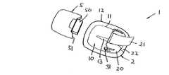
具体的には、図1は、モジュール式皮膚接触型薬剤送達装置1の形態の医療装置の斜視図を示し、薬剤送達装置1はパッチユニット2及びポンプユニット5を備える(ポンプユニットは容器を含むので、ポンプユニットは容器ユニットと表記することもできる)。ユーザに提供されるとき、これらのユニットの各々は、各ユニット固有の密閉パッケージ(図示せず)に梱包されることが好ましい。図1に示す実施形態はパッチユニットを備え、このパッチユニットには、挿入可能な皮膚穿刺装置、例えば針、カニューレ、又はセンサを取り付ける。実際の実施形態において、パッチユニットを皮膚に取り付け、皮膚穿刺装置を挿入しないとポンプユニット又は他のユニットを取り付けられない場合、それに対応する使用方法が採用される。First, according to FIGS. 1-3, one embodiment of a medical device for drug administration focuses on a user-driven function that allows the user to be directly involved while the device is mainly applied to the skin surface. While explaining. The
Specifically, FIG. 1 shows a perspective view of a medical device in the form of a modular skin contact
パッチユニットは、ユーザの皮膚に装着するのに適した下部接着接触面を有する可撓性パッチ部分10と、ハウジング部分20とを含み、このハウジング部分には皮膚穿刺装置(図示せず)が収容される。この皮膚穿刺装置はユーザの皮膚を貫通する遠位尖端を含み、且つポンプユニットと流体連通する位置に配置される。図示の実施形態では、皮膚穿刺装置の尖鋭端は初期位置と突出位置の間を移動することができ、初期位置では、尖端は皮膚接触面から後退し、突出位置では、尖端は皮膚接触面から飛び出す。更に、皮膚穿刺装置は突出位置と後退位置の間を移動することができ、突出位置では遠位端は皮膚接触面から飛び出し、後退位置では皮膚接触面から後退する。
パッチユニットは更に、作動手段が作動するときに皮膚穿刺装置を初期位置と第2位置の間で移動させる第1細片部材21の形態のユーザ把持作動手段と、パッチを皮膚表面から剥がす第2ユーザ把持細片部材22とを含む。第2細片を使用して、皮膚穿刺装置の遠位端を、突出位置と後退位置の間で移動させることもできる。ハウジングは更に、弾性構造フック部材ペアの形態のユーザ作動雄嵌合手段31を含み、雄嵌合手段は、ポンプユニット上の該当する雌嵌合手段51と嵌合して、ポンプユニットを解放可能に使用状態のパッチユニットに固定することができる。可撓性隆起支持部材13はハウジングからから延出し、パッチの上側表面11に取り付けられる。接着面はユーザに剥離可能な保護シートが付いた状態で提供される。The patch unit includes a
The patch unit further includes user gripping actuating means in the form of a
ソフトカニューレを導入する挿入機構を備える別のパッチユニットが、本出願と同じ出願人が保有するPCT/EP2006/050410に開示されており、この特許文献をここで参照することによりその内容を本明細書に組み込む。この別のユニットは、ポンプユニットを取り付ける前に皮膚表面に装着され、ポンプユニットを取り付けることにより挿入機構が解放される。
ポンプユニット5は、薬液製剤(例えば、インスリン)を収容するプレフィルド容器と、使用状態において薬剤を容器から針を通して放出する放出アセンブリとを含む。容器ユニットは、パッチ部分の上側表面に取り付けられるほぼ平坦な下側表面を有し、且つハウジング部分20の該当する空洞に収容される突出部分50と、ニードルユニット上の該当するフック部材31と嵌合する雌嵌合手段51とを含む。突出部分は2つのユニットの間のインターフェースとなり、且つポンプ放出口及びコンタクト手段(図示せず)を含み、ポンプは、コンタクト手段によってポンプがパッチに組み立てられていることを検出することができる。Another patch unit with an insertion mechanism for introducing a soft cannula is disclosed in PCT / EP2006 / 050410 owned by the same applicant as the present application, the contents of which are hereby incorporated herein by reference. Include in the book. This other unit is attached to the skin surface before attaching the pump unit, and the insertion mechanism is released by attaching the pump unit.
The pump unit 5 includes a prefilled container that contains a drug formulation (eg, insulin) and a release assembly that releases the drug from the container through the needle in use. The container unit has a substantially flat lower surface that is attached to the upper surface of the patch portion and fits with a protruding
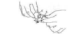
使用状態では、ユーザは2つのユニットを組み立て、次にこれらのユニットは皮膚表面に装着され、その後、皮膚穿刺装置が挿入され、ポンプが作動する準備が整う。動作は皮膚穿刺装置が挿入されると自動的に始まるか、又はポンプは以下に説明するようにリモートユニットによって作動を開始することができる。ポンプユニットをパッチユニットに取り付ける前に、ユーザは普通、ポンプユニットをリモートユニットと、以下に説明するようにペアとして組み立てることになる。別の使用状態では、ユーザはまず、パッチユニットを皮膚表面に装着し、皮膚穿刺装置を挿入することができ、その後、ポンプユニットをパッチユニットに取り付ける。
組み立て済み装置を、パッチユニットの使用推奨期間(例えば、48時間)に渡って所定の位置においた後、又は容器が空になった場合、或いは他の理由により、剥離用片22を把持して引っ張ることにより装置を皮膚から取り外す。これによって皮膚穿刺装置を後退させることもできる。ポンプユニットはパッチユニットから、パッチユニットが皮膚から剥がされる前又は後に取り外すことができる。その後、ポンプユニットが空になるまで、又はパッチを再び取り替える必要があるまで、ポンプユニットは新規のパッチユニットと一緒に再度使用することができる。In use, the user assembles the two units, which are then mounted on the skin surface, after which the skin puncture device is inserted and the pump is ready to operate. Operation begins automatically when the skin puncture device is inserted, or the pump can be activated by the remote unit as described below. Prior to attaching the pump unit to the patch unit, the user will typically assemble the pump unit with the remote unit as a pair as described below. In another use state, the user can first attach the patch unit to the skin surface and insert a skin puncture device, and then attach the pump unit to the patch unit.
After holding the assembled device in place over the recommended period of use of the patch unit (eg 48 hours), or when the container is empty, or for other reasons, Remove the device from the skin by pulling. Accordingly, the skin puncture device can be retracted. The pump unit can be removed from the patch unit before or after the patch unit is peeled from the skin. The pump unit can then be used again with a new patch unit until the pump unit is empty or until the patch needs to be replaced again.
図4は、ハウジングの上側部分を取り外した状態のポンプユニットを示している。ポンプユニットは、容器760と、放出アセンブリとを備え、放出アセンブリは、ポンプアセンブリ300だけでなく、プロセッサ手段580、及びプロセッサ手段を制御して動作させるコイルアクチュエータ581を含む。ポンプアセンブリは、皮下埋込型デバイスとの接続を行なう放出口322と、開口323とを含み、この開口323によって、ポンプアセンブリに収容される流体コネクタを作動させることができ、従ってポンプアセンブリを容器に接続することができる。容器760は事前充填式可撓性折り畳み式ポーチの形態であり、この折り畳み式ポーチは、ポンプアセンブリと流体連通する位置に配置される針貫通可能な隔壁を含む。ハウジングの下側部分は透明領域(図示せず)を含み、透明領域によってユーザは容器の一部分を調査することができる。図示のポンプアセンブリは機械作動型膜ポンプであるが、容器及び放出手段はいずれかの適切な構造とすることができる。
プロセッサ手段は種々の要素を含むが、特に、ポンプ作動を制御するマイクロプロセッサ583の接続先となるPCB又はフレキシブルプリント基板と、パッチユニット又はリモートユニットの上の該当するコンタクトアクチュエータと連携動作するコンタクト(即ち、センサ)588、589と、聴覚及び/又は触覚信号を生成する信号生成手段585と、ディスプレイ(設ける場合の)と、メモリと、送信機と、受信機とを含む。エネルギーソース586がエネルギーを供給する。これらのコンタクトは膜によって保護することができ、これらの膜はハウジングの可撓性部分によって構成することができる。FIG. 4 shows the pump unit with the upper part of the housing removed. The pump unit comprises a
The processor means includes various elements. In particular, the PCB or flexible printed circuit board to which the microprocessor 583 for controlling the pump operation is connected and the contact (in cooperation with the corresponding contact actuator on the patch unit or the remote unit) ( That is, it includes
図1〜4を参照しながら、ポンプユニット及びパッチユニットを備えるモジュール式ローカルユニットについて説明してきたが、ローカルユニットは一体型ユニットとして提供することもできる。
本発明について、図1〜5に開示するポンプユニット及びリモートコントローラユニットを参照しながら説明してきたが、本開示内容は、被験者に対して薬剤送達を行なう全ての形態のシステムに広く適用することができることを理解されたい。例えば、本開示内容は、多数の製造業者が現在市販している種類のプログラム可能な携帯型インスリン注入ポンプに適用することができ、製造業者としては、これらには制限されないが、例えばPARADIGMという登録商標を持つMedtronic MiniMed、OmniPodという登録商標を持つInsulet Corporation、Deltec COZMOという登録商標を持つSmiths Medical、及びその他の会社を挙げることができ、これらのポンプにはリモートコントロールが設けられるか、又はこれらのポンプはリモートコントロールと一緒に使用することができる。Although the modular local unit comprising a pump unit and a patch unit has been described with reference to FIGS. 1-4, the local unit can also be provided as an integral unit.
Although the present invention has been described with reference to the pump unit and remote controller unit disclosed in FIGS. 1-5, the present disclosure may be widely applied to all forms of systems for delivering medication to a subject. Please understand that you can. For example, the present disclosure can be applied to a programmable portable insulin infusion pump of the type currently marketed by many manufacturers, including, but not limited to, a registration called PARADIGM, for example. The trademarked Medtronic MiniMed, the Insul Corporation with a registered trademark of OmniPod, the Smiths Medical with the registered trademark of Deltec COZMO, and other companies may include remote controls on these pumps, or The pump can be used with a remote control.
図5は、プロセスユニット200(ここでは、図1のポンプユニット5に対応する)、及びコントローラユニット100(ここでは、ポンプユニット用の「リモートコントローラ」又は「外部通信装置」の形態である)の模式図を示している。このようなユニットの一般的な構造はこの技術分野の当業者には公知であるが、本発明の所望機能を提供するために必要な回路についての更に詳細な説明に関しては、本明細書に組み込まれる米国特許出願公開第2003/0065308号を参照されたい。
具体的には、図5は、ポンプユニット200及びリモートコントローラ100に収容される種々の機能部品又はモジュール(即ち、単一部品群又は部品グループ群)の簡易ブロック図を示している。リモートコントローラユニットはハウジング101と、CPU、制御プログラム及び動作データを保存するメモリ要素、及びクロックを含むリモートプロセッサ110と、操作情報をユーザに提供するLCDディスプレイ120と、ユーザからの入力を可能にするキーパッド130と、情報をユーザに提供する音声アラーム140と、情報をユーザに提供するバイブレータ150と、電力をコントローラに供給するメインバッテリ160と、コントローラのメモリ保持を行なうバックアップバッテリ161と、信号をポンプユニットに送信する無線周波数(RF)遠隔テレメトリー送信機170と、信号をポンプユニットから受信する無線周波数(RF)遠隔テレメトリー受信機180と、第2送信機190とを備える。コントローラは更に、ポート185、例えば赤外線(IR)ポート又はRF入力/出力システムを含む、又は別のデバイス、例えば血中グルコース測定器(BGM)、血中グルコース連続測定装置(CGM)、PC、又はPDAと通信するUSBポートを含む。FIG. 5 shows a process unit 200 (here corresponding to the pump unit 5 in FIG. 1) and a controller unit 100 (here in the form of a “remote controller” or “external communication device” for the pump unit). A schematic diagram is shown. The general structure of such units is well known to those skilled in the art, but is incorporated herein for a more detailed description of the circuitry necessary to provide the desired functionality of the present invention. U.S. Patent Application Publication No. 2003/0065308.
Specifically, FIG. 5 shows a simplified block diagram of various functional components or modules (ie, a single component group or component group group) housed in the
図5に更に示すように、ポンプユニット200はハウジング201と、CPU、及び制御プログラム及び動作データを保存するメモリ要素を含むローカルプロセッサ電子機器210と、電力をシステムに供給するバッテリ260と、通信信号をリモートユニットに送信するプロセスユニットRFテレメトリー送信機270と、信号をリモートユニットから受信するプロセスユニット無線周波数(RF)テレメトリー受信機280と、第2プロセスユニット受信機240(この受信機は、フィードバックをユーザに供給する音声アラームに使用される音響トランスデューサのコイルの形態とすることができる)と、薬剤を収容する容器230と、容器から皮膚穿刺装置を介して患者の体内に薬剤を放出するポンプアセンブリ220とを含む。別の実施形態では、ポンプユニットは更に、情報をユーザに提供するLCDディスプレイと、ユーザからの入力を可能にするキーパッドと、情報をユーザに提供するバイブレータ又は他の触覚アクチュエータと、を含むことができる。RF送信はBluetooth(登録商標)のような標準プロトコルに従って行なうことができる。 As further shown in FIG. 5, the
図21Aは、図1に示すタイプの医療装置1000の一実施形態を示す。医療装置1000は、カニューレユニット1010及びカニューレユニットに取り付け可能なポンプ(又は容器)ユニット1050を備えるが、図1の実施形態のような針挿入機構ではなく、PCT/EP2006/050410に開示されているようなカニューレ挿入機構が使用される。図示の実施形態では、カニューレユニットは、シャフト付きのハウジング1015を含み、ハウジングには、ポンプユニットの一部分1051が挿入される。シャフトは開口1012を有する蓋部分1011を有し、蓋の自由端は下側突起(図示せず)を有する可撓性ラッチ部材1013を構成し、下側突起はポンプユニットの該当する凹部1052と嵌合し、これにより、ポンプユニットがカニューレユニットのシャフトに挿入されるとスナップ嵌合が行なわれる。更に、通気開口1054を観察することができる。ハウジング1015には対向脚ペア1018が設けられ、ハウジングは皮膚接触面として機能する下側接着面1020を有する可撓性シート部材1019の上部に取り付けられ、シート部材はカニューレ1017用の開口1016を含む。 FIG. 21A shows one embodiment of a
図示のように、カニューレは、カニューレユニットのハウジングから傾斜角で延出し、皮膚表面を貫通するカニューレ挿入部位を例えば挿入直後に検査できるように配置される(図では、カニューレ全体を見ることができる)。図示の実施形態では、蓋の開口は挿入部位の検査容易性を向上させる。ポンプユニットがカニューレユニットに接続されると、ポンプユニットはカニューレ及び挿入部位を完全に覆い、且つ外部からの影響、例えば水、埃、及び機械力の影響から保護する(図21B参照)が、ポンプユニットは取り外し可能にカニューレユニットに接続されるので、ポンプユニットをカニューレユニットから解放し(ラッチ部材を持ち上げることにより)、完全に又は部分的に引き出すことができ、よって挿入部位をいつでも検査することができる。このような構成により、皮膚穿刺装置、例えば図示のソフトカニューレを有する薬剤送達装置が提供される。本装置は、通常の使用の間は非常に良好に保護されるが、ポンプユニットを完全に又は部分的に取り外すことにより、必要に応じて検査することができる。実際、この装置は、少なくとも或る程度、ポンプを装着している間にも、例えば該当する開口又は透明領域により、挿入部位を検査可能に作製することができる。しかしながら、装着するポンプは、装着中には挿入部位が完全に又は部分的に塞がれて検査できないものの、使用中に挿入部位を非常に堅牢に保護することができる。
図示の実施形態では、傾斜したカニューレを使用するが、別の実施形態では、図7に示すタイプの針機構は、挿入ポイントをニードルユニットの嵌合部分に近付けて、このような垂直方向に挿入した様子も、ポンプユニットを取り外すことにより検査可能とした場合に使用することができる。As shown, the cannula extends from the cannula unit housing at an angle of inclination and is positioned so that the cannula insertion site that penetrates the skin surface can be examined, for example, immediately after insertion (in the figure, the entire cannula can be seen. ). In the illustrated embodiment, the lid opening improves the ease of inspection of the insertion site. When the pump unit is connected to the cannula unit, the pump unit completely covers the cannula and insertion site and protects it from external influences such as water, dust and mechanical forces (see FIG. 21B). Since the unit is removably connected to the cannula unit, the pump unit can be released from the cannula unit (by lifting the latch member) and fully or partially withdrawn so that the insertion site can be examined at any time. it can. Such a configuration provides a drug delivery device having a skin puncture device, such as the soft cannula shown. The device is very well protected during normal use, but can be inspected as needed by completely or partially removing the pump unit. In fact, the device can be made inspectable at the insertion site, for example by means of the corresponding opening or transparent area, even at least to some extent while the pump is mounted. However, the pump to be installed can protect the insertion site very firmly during use, although the insertion site is completely or partially blocked during installation and cannot be examined.
In the illustrated embodiment, an inclined cannula is used, but in another embodiment, a needle mechanism of the type shown in FIG. 7 is inserted in such a vertical direction with the insertion point close to the mating portion of the needle unit. This state can also be used when inspection is possible by removing the pump unit.
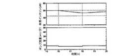
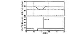
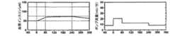
以下に、本発明の態様を図6〜20を参照しながら説明する。図6、7、及び10〜20の各図は2つのグラフを示す。1番目の図は、2番目の図に示す対応するポンプ流量プロファイルによって実現する血漿インスリンプロファイルを示している。
本発明に関する説明を行なう前に、図6及び7では、血漿インスリンプロファイル、及び血漿インスリンプロファイルの原因となる該当するポンプ流量分布が、先行技術における通常の送達ポンプに関して示される。図示のように、ポンプ流量を単純に増やす(図6)か又は減らす(図7)ことにより得られる血漿インスリンプロファイルは、血漿インスリンプロファイルの所望の変化、即ちポンプ流量分布によって示される変化とは著しく異なる。得られる血漿インスリンプロファイルは、以下のモデル及び公式を使用して計算される。Below, the aspect of this invention is demonstrated, referring FIGS. Each of FIGS. 6, 7, and 10-20 shows two graphs. The first diagram shows the plasma insulin profile achieved by the corresponding pump flow profile shown in the second diagram.
Prior to describing the present invention, in FIGS. 6 and 7, the plasma insulin profile and the corresponding pump flow distribution responsible for the plasma insulin profile are shown for a conventional delivery pump in the prior art. As shown, the plasma insulin profile obtained by simply increasing (FIG. 6) or decreasing (FIG. 7) the pump flow rate is significantly different from the desired change in plasma insulin profile, ie the change indicated by the pump flow distribution. Different. The resulting plasma insulin profile is calculated using the following model and formula.
以下に、インスリン送達に関する簡単な2室モデルについて説明する。このモデルは本発明の原理を示すのに役立つ。このモデルは次の要素により特徴付けられる。
1)P=ポンプ流量:に対応する注入された皮下貯蔵部位
2)T1/2=皮下貯蔵部位からの吸収:によって特徴付けられる血液への吸収
3)V=分布容積:によって特徴付けられる血漿中濃度
4)Cl=血液からのクリアランス:によって特徴付けられる血液からの排泄
このような系では、次のモデル方程式を適用することができる。
dD/dt=P(t)−k・D k=ln(2)/T1/2
dCp/dt=(k・D)/V−α・Cp α=Cl/V
上式中、
D:皮下貯蔵部位におけるインスリンの送達量又は量(U)
P:ポンプ流量(U/分)
k:皮下貯蔵部位からの吸収の時定数(1/分)
Cp:血漿中インスリン濃度(U/L)
V:インスリン分布容積(L)
Cl:インスリンクリアランス(L/分)
である。
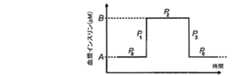
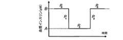
上の方程式から、どのようにして血漿中インスリン濃度を注入流量P0に対応する濃度Aから注入流量P2に対応する濃度Bに上げ、血漿中インスリン濃度を元の濃度Aに下げるかを判断することができ、この場合、AからBへの遷移期間、及びBからAの遷移期間における注入流量はP1及びP3とそれぞれ表記される(図8参照)。
P0=Cl・A・n n=1/6000(pmol/U)
P1=P0+P1*=P0+n・(B−A)・Cl/(k・Δt) Δt=n・(B−A)・Cl/(k・P1*)
上の式では、P1*は選択されるポンプ流量であり、Δtは皮下貯蔵部位を充填するために要する該当時間である。Δtが経過した後、ポンプ流量はP2に変化する。
P2=Cl・B・n
P3=0 Δt=−ln(A/B)/k
上の式では、Δtは、BからAへの血漿中濃度変化に対応して皮下貯蔵部位のサイズが変化するのに要する時間である。The following describes a simple two-chamber model for insulin delivery. This model serves to illustrate the principles of the present invention. This model is characterized by the following elements:
1) P = pump flow rate: infused subcutaneous storage site corresponding to 2) T1/2 = absorption from subcutaneous storage site: absorption into blood characterized by 3) V = plasma characterized by distribution volume: Medium concentration 4) Cl = clearance from blood: elimination from blood characterized by: In such a system, the following model equation can be applied:
dD / dt = P (t) −k · D k = ln (2) / T1/2
dCp / dt = (k · D) / V−α · Cp α = Cl / V
In the above formula,
D: Amount or amount of insulin delivered (U) at the subcutaneous storage site
P: Pump flow rate (U / min)
k: Time constant of absorption from the subcutaneous storage site (1 / min)
Cp : plasma insulin concentration (U / L)
V: insulin distribution volume (L)
Cl: Insulin clearance (L / min)
It is.
From the above equation, it is determined how to increase the plasma insulin concentration from the concentration A corresponding to the infusion flow rate P0 to the concentration B corresponding to the infusion flow rate P2 and lower the plasma insulin concentration to the original concentration A. In this case, the injection flow rates in the transition period from A to B and in the transition period from B to A are denoted as P1 and P3 , respectively (see FIG. 8).
P0 = Cl · A · n n = 1/6000 (pmol / U)
P1 = P0 + P1* = P0 + n · (B−A) · Cl / (k · Δt) Δt = n · (B−A) · Cl / (k · P1* )
In the above equation, P1* is the selected pump flow rate and Δt is the time required to fill the subcutaneous storage site. After Δt has elapsed, the pump flow rate is changed to P2.
P2 = Cl · B · n
P3 = 0 Δt = −ln (A / B) / k
In the above equation, Δt is the time required for the size of the subcutaneous storage site to change in response to a change in plasma concentration from B to A.
上の方程式から、血漿中インスリン濃度を、注入流量P0に対応する濃度Bから注入流量P2に対応する濃度Aに下げる方法、及び元の濃度Bに上げる方法を判断することができ、この場合、BからAへの遷移期間、及びAからBへの遷移期間における注入流量はP1及びP3とそれぞれ表記される(図9参照)。
P0=Cl・B・n n=1/6000(pmol/U)
P3=P2+P3*=P2+n・(B−A)・Cl/(k・Δt) Δt=n・(B−A)・Cl/(k・P3*)
上の式では、P3*は選択されるポンプ流量であり、Δtは皮下貯蔵部位を充填するために要する該当時間である。Δtが経過した後、ポンプ流量はP2に変化する。
P2=Cl・A・n
P1=0 Δt=−ln(A/B)/k
上の式では、Δtは、BからAへの血漿中濃度変化に対応して皮下貯蔵部位のサイズが変化するのに要する時間である。From the above equation, it is possible to determine how to lower the plasma insulin concentration from the concentration B corresponding to the infusion flow rate P0 to the concentration A corresponding to the infusion flow rate P2 and to the original concentration B. In this case, the injection flow rates in the transition period from B to A and the transition period from A to B are denoted as P1 and P3 , respectively (see FIG. 9).
P0 = Cl · B · n n = 1/6000 (pmol / U)
P3 = P2 + P3* = P2 + n · (B−A) · Cl / (k · Δt) Δt = n · (B−A) · Cl / (k · P3* )
In the above equation, P3* is the selected pump flow rate and Δt is the time required to fill the subcutaneous storage site. After Δt has elapsed, the pump flow rate is changed to P2.
P2 = Cl · A · n
P1 = 0 Δt = −ln (A / B) / k
In the above equation, Δt is the time required for the size of the subcutaneous storage site to change in response to a change in plasma concentration from B to A.
次の実施例では以下の値を使用したが、これらの値は人によって変わるだけでなく、同じ人に関しても時間の経過と共に変化するので、例示に過ぎないことに留意されたい。
T1/2=126分
V=10L
Cl=1L/分The following values were used in the following examples, but it should be noted that these values are exemplary only because they change not only from person to person but also to the same person over time.
T1/2 = 126 minutes V = 10L
Cl = 1L / min
図10〜20を参照すると、血漿中インスリン濃度に所望の変化を達成するための異なる方法が示される。得られる血漿インスリンプロファイルは上述のモデル及び公式を使用して計算される。ポンプ流量が非常に大きい場合、図示のポンプ流量50mU/分に乗じる必要のある係数が示される。図示の分布を生成するために使用する計算では、血漿中インスリン濃度が開始ポイントとして使用されているので、注入流量が非整数になる。しかしながら、別の構成では、従来の整数の注入流量をユーザが設定できる。例えば、図10〜13では、血漿インスリンが50pMから65pMに30%だけ所望の増加を達成するようにポンプ流量を増やしている。これは、8.33mU/分及び10.83mU/分の計算による注入流量に対応する。図14〜17では、約8.33mU/分及び7.08mU/分の計算による注入流量に対応して、50pMから42.5pMに血漿中インスリン濃度が15%だけ所望の減少を達成するように、ポンプ流量を減らしている。
従って、図10は、2時間の期間に渡ってユーザがポンプ流量を、約8.33mU/分及び10.83mU/分の計算による注入流量に対応する50pMから65pMに血漿中インスリン濃度が30%だけ増えるように増やしたい状態を示している。With reference to FIGS. 10-20, different methods for achieving a desired change in plasma insulin concentration are shown. The resulting plasma insulin profile is calculated using the model and formula described above. If the pump flow rate is very high, the factor that needs to be multiplied by the illustrated pump flow rate of 50 mU / min is shown. In the calculations used to generate the distribution shown, the infusion flow rate is non-integer since the plasma insulin concentration is used as the starting point. However, in another configuration, the user can set a conventional integer injection flow rate. For example, in FIGS. 10-13, the pump flow rate is increased so that plasma insulin achieves the desired increase by 30% from 50 pM to 65 pM. This corresponds to an injection flow rate calculated by 8.33 mU / min and 10.83 mU / min. 14-17, to achieve a desired decrease in plasma insulin concentration of 15% from 50 pM to 42.5 pM, corresponding to the infusion flow calculated at about 8.33 mU / min and 7.08 mU / min. Reduce the pump flow.
Thus, FIG. 10 shows that over a 2 hour period, the user can change the pump flow rate from 50 pM to 65 pM corresponding to the infusion flow calculated by about 8.33 mU / min and 10.83 mU / min, with a plasma insulin concentration of 30%. It shows the state that wants to increase as much as possible.
しかしながら、ポンプ流量を図6に示すように単に30%だけ増やすのではなく、ポンプ流量分布400を本発明の一態様に従って変化させる。具体的には、薬剤の送達流量を、第1送達流量から、第1送達流量より大きい第2送達流量に、一定の時間内で変更する方法を使用し(第1送達流量はゼロより大きい)、当該方法は、薬剤を第1送達流量(401)で送達するステップと、時間区間の開始時点で、薬剤を第3送達流量(403)で第1期間に渡って送達するステップと、第1期間の後に、薬剤を第2送達流量(402)で送達するステップと、時間区間の最後に、薬剤を第4送達流量(404)(この場合はゼロ)で第2期間に渡って送達するステップと、第2期間の後に、再度薬剤を第1送達流量で送達するステップとを含む。
図10に示すように、時間区間の一部分を使用して血漿中濃度を所望の濃度に増やすと、時間区間後の一定の期間の血漿中濃度は初期血漿中濃度よりも高まる。この状態を補正するために、図11に示すように、ポンプ流量を時間区間の開始時点の前に増やすことで、所望の高い血漿中濃度を全時間区間内で達成することができる。時間区間が予め分かっている場合、プロセッサによって制御される薬剤投与システムは、第3注入流量での注入を開始すべき時間を計算する(上述の公式を使用して)ことができる。血漿中濃度が時間区間の終了時点の後に高くなることを避けるため、ポンプ流量を時間区間の終了時点の前に減らすことができ、これにより、所望の低い血漿中濃度を時間区間の後に達成することができる(図12参照)。図11の状態に示されるように、プロセッサによって制御される薬剤投与システムは、第4注入流量での注入を開始すべき時間を計算する(上述の公式を使用して)ことができる。However, rather than simply increasing the pump flow rate by 30% as shown in FIG. 6, the pump
As shown in FIG. 10, when the plasma concentration is increased to a desired concentration using a part of the time interval, the plasma concentration in a certain period after the time interval is higher than the initial plasma concentration. To correct for this condition, the desired high plasma concentration can be achieved within the entire time interval by increasing the pump flow rate before the start of the time interval, as shown in FIG. If the time interval is known in advance, the drug delivery system controlled by the processor can calculate (using the above formula) the time at which the infusion at the third infusion flow should begin. In order to avoid the plasma concentration becoming higher after the end of the time interval, the pump flow can be reduced before the end of the time interval, thereby achieving the desired low plasma concentration after the time interval. (See FIG. 12). As shown in the state of FIG. 11, the processor-controlled drug delivery system can calculate (using the above formula) the time at which the infusion at the fourth infusion flow should begin.
第2注入流量に対応する血漿中濃度により速く到達するために、更に高い第3注入流量403’を使用することができるが、これにより「オーバーシュート」408が発生し、血漿中濃度が所望濃度よりも高くなる。このようなオーバーシュートを補正するために、所望の第2ポンプ流量に増やす前に、ポンプ流量を次に、第5注入流量405に一定の期間だけ減らす(図13参照)。どの位速く新規濃度に到達する必要があり、且つどの位の大きさのオーバーシュートを許容することができるかを、必要に応じて選択することができる。 A higher third infusion flow 403 'can be used to reach the plasma concentration corresponding to the second infusion flow faster, but this results in an "overshoot" 408 and the plasma concentration is the desired concentration. Higher than. In order to correct such overshoot, the pump flow rate is then reduced to a fifth injection flow rate 405 for a fixed period before increasing to the desired second pump flow rate (see FIG. 13). It can be selected as needed how fast a new concentration needs to be reached and how much overshoot can be tolerated.
図14は、ユーザが2時間に渡って、8.33mU/分及び7.08mU/分の計算による注入流量に対応して50pMから42.5pMに血漿中インスリン濃度が15%だけ減るようにポンプ流量を下げようとする状態を示している。しかしながら、図7に示すように、ポンプ流量を単純に15%だけ減らすのではなく、ポンプ流量分布410を本発明の更に別の態様に従って変化させる。実際には、この操作の原理は、ポンプ流量を上の例における時間区間に渡って増やしたときに使用される原理と同じであり、増やす操作及び減らす操作の順番を入れ替えている。具体的には、薬剤の送達流量を、第1送達流量から、第1送達流量より小さい第2送達流量に一定の時間内で変更する(第2送達流量はゼロより大きい)方法は、薬剤を第1送達流量(411)で送達するステップと、時間区間の開始時点で、薬剤を、第2送達流量より小さい第3送達流量(413)(ここではゼロ)で第1期間に渡って送達するステップと、第1期間の後に、薬剤を第2送達流量(412)で送達するステップと、第1時間区間の最後に、薬剤を、第1送達流量より大きい第4送達流量(414)で第2期間に渡って送達するステップと、第2期間の後に、薬剤を第1送達流量で送達するステップとを含む。
図14に示すように、時間区間の一部分を使用して血漿中濃度を所望濃度に減らしており、同様に時間区間の後の一定の期間の血漿中濃度が初期血漿中濃度より低くなっている。この状態を補正するために、図15に示すように、ポンプ流量を時間区間の開始時点の前に減らすことにより、所望の低い血漿中濃度を全時間区間内で達成することができる。時間区間が予め分かっている場合、プロセッサによって制御される薬剤投与システムは、第3注入流量での注入を開始すべき時間を計算する(上述の公式を使用して)ことができる。血漿中濃度が時間区間の終了時点の後に低くなることを避けるために、ポンプ流量を時間区間の終了時点の前に増やすことができ、これにより、所望の高い血漿中濃度を時間区間の後に達成することができる(図16参照)。図15の状態におけるように、プロセッサによって制御される薬剤投与システムは、第4注入流量での注入を開始すべき時間を計算する(上述の公式を使用して)ことができる。FIG. 14 shows that the user pumps the plasma insulin concentration by 15% from 50 pM to 42.5 pM corresponding to the infusion flow calculated by 8.33 mU / min and 7.08 mU / min over 2 hours. The state which is going to reduce the flow rate is shown. However, as shown in FIG. 7, rather than simply reducing the pump flow rate by 15%, the
As shown in FIG. 14, a part of the time interval is used to reduce the plasma concentration to the desired concentration, and similarly, the plasma concentration for a certain period after the time interval is lower than the initial plasma concentration. . To correct this condition, the desired low plasma concentration can be achieved within the entire time interval by reducing the pump flow before the start of the time interval, as shown in FIG. If the time interval is known in advance, the drug delivery system controlled by the processor can calculate (using the above formula) the time at which the infusion at the third infusion flow should begin. In order to avoid lowering plasma concentrations after the end of the time interval, the pump flow can be increased before the end of the time interval, thereby achieving the desired high plasma concentration after the time interval. (See FIG. 16). As in the state of FIG. 15, the processor-controlled drug delivery system can calculate (using the above formula) the time at which the infusion at the fourth infusion flow should begin.
時間区間の終了時点の後に初期の第1注入流量に対応する血漿中濃度により速く到達するために、更に高い第4注入流量414’を使用することができ、これにより「オーバーシュート」418が発生し、血漿中濃度が所望濃度よりも高くなる。このようなオーバーシュートを補正するため、所望の第2ポンプ流量に増やす前に、続く一定の期間だけポンプ流量を第5注入流量415に減らす(図17参照)。どの位速く新規濃度に到達する必要があり、且つどの位の大きさのオーバーシュートを許容することができるかを、必要に応じて選択することができる。 To reach the plasma concentration corresponding to the initial first infusion flow faster after the end of the time interval, a higher fourth
図6及び7には、血漿インスリンプロファイル、及び当該分布が生じる原因となる該当するポンプ流量分布が、先行技術による通常の注入ポンプに関して示されている。図18は、「デュアルウェーブ」ボーラスが2時間に渡って注入される対応する例を示している。図示のように、単純にポンプ流量を増やした後減らすことにより、得られる血漿インスリンプロファイルは、血漿インスリンプロファイルに関して想定できる所望の変化、即ちポンプ流量分布によって示される変化形状とは著しく異なる。
血漿インスリンプロファイルをデュアルウェーブボーラス注入において目的とするプロファイルにより近づけるために、本発明の原理を図19及び20に示すように適用した。実際に、これらの実施例は、上述の注入流量をそれぞれ増やす及び減らす2つの実施例の組み合わせに対応する。具体的には、図19の実施形態では図10の実施形態に用いる原理を使用するが、図20の実施形態では図13の実施形態に用いる原理を使用し、即ちオーバーシュートが発生した後に注入流量を減らして補正を行なう。図示のように、図19及び20に示す本発明によって実現する血漿中濃度は、所望のデュアルウェーブ分布にずっと近い。In FIGS. 6 and 7, the plasma insulin profile and the corresponding pump flow distribution responsible for the distribution are shown for a conventional infusion pump according to the prior art. FIG. 18 shows a corresponding example in which a “dual wave” bolus is infused over 2 hours. As shown, by simply increasing and decreasing the pump flow rate, the resulting plasma insulin profile is significantly different from the desired change that can be assumed for the plasma insulin profile, i.e., the change shape exhibited by the pump flow distribution.
In order to bring the plasma insulin profile closer to the desired profile in dual wave bolus injection, the principles of the present invention were applied as shown in FIGS. In fact, these embodiments correspond to a combination of two embodiments that increase and decrease the injection flow rate described above, respectively. Specifically, in the embodiment of FIG. 19, the principle used in the embodiment of FIG. 10 is used, but in the embodiment of FIG. 20, the principle used in the embodiment of FIG. 13 is used. Reduce the flow rate to correct. As shown, the plasma concentrations achieved by the present invention shown in FIGS. 19 and 20 are much closer to the desired dual wave distribution.
好適な実施形態に関する上述の説明では、説明した機能を種々の構成要素に実現する種々の構造及び手段について、当業者が本発明のコンセプトを明確に理解できるように記載した。種々の構成要素に関する詳細な構成及び仕様は、本明細書に開示される基本原理に沿って当業者が実行する通常の設計手順の目的である。 In the above description of the preferred embodiments, various structures and means for implementing the described functions in various components have been set forth in order to enable those skilled in the art to clearly understand the concept of the present invention. Detailed configurations and specifications for the various components are the purpose of normal design procedures performed by those skilled in the art in accordance with the basic principles disclosed herein.
Claims (44)
Translated fromJapanese−薬剤を第1送達流量(401)で送達するステップと、
−薬剤を、第2送達流量より大きい第3送達流量(403)で第1期間に渡って送達するステップと、
−第1期間の後に、薬剤を第2送達流量(402)で送達するステップと
を含む方法。A method of changing a drug delivery flow rate from a first delivery flow rate to a second delivery flow rate that is greater than the first delivery flow rate, comprising:
-Delivering the drug at a first delivery flow rate (401);
-Delivering the drug over a first time period at a third delivery flow rate (403) greater than the second delivery flow rate;
Delivering a drug at a second delivery flow rate (402) after the first period.
−第1期間の後に、薬剤を、ゼロよりも大きな第2送達流量より小さい第4送達流量(405)で、第2期間に渡って送達するステップを含む、請求項1記載の方法。Furthermore,
The method of claim 1, comprising: after the first period, delivering the medicament over a second period at a fourth delivery flow rate (405) that is less than the second delivery flow rate greater than zero.
−第1送達流量を変更する前に、第一送達流量より大きい第2送達流量を設定するステップを含む、請求項1ないし4のいずれか一項に記載の方法。Furthermore,
5. A method according to any one of the preceding claims, comprising the step of setting a second delivery flow rate that is greater than the first delivery flow rate before changing the first delivery flow rate.
−薬剤を第1送達流量(411)で送達するステップと、
−薬剤を、第2送達流量より小さい第3送達流量(413)で第1期間に渡って送達するステップと、
−第1期間が経過した後、薬剤を第2送達流量(412)で送達するステップと
を含む方法。A method of changing a drug delivery flow rate from a first delivery flow rate to a second delivery flow rate that is less than the first delivery flow rate and greater than zero, comprising:
-Delivering the drug at a first delivery flow rate (411);
-Delivering the drug over a first time period at a third delivery flow rate (413) less than the second delivery flow rate;
Delivering a drug at a second delivery flow rate (412) after the first period has elapsed.
−第1送達流量を変更する前に、第一送達流量より小さい第2送達流量を設定するステップを含む、請求項7ないし9のいずれか一項に記載の方法。Furthermore,
10. A method according to any one of claims 7 to 9, comprising the step of setting a second delivery flow rate that is smaller than the first delivery flow rate before changing the first delivery flow rate.
−請求項1ないし6のいずれか一項に記載の方法に従って薬剤送達流量を増やすステップと、
−請求項7ないし11のいずれか一項に記載の方法に従って薬剤の送達流量を減らすステップと
を含む方法。A method for changing a drug delivery flow rate, comprising:
-Increasing the drug delivery flow rate according to the method of any one of claims 1 to 6;
-Reducing the drug delivery flow rate according to the method of any one of claims 7-11.
−請求項7ないし11のいずれか一項に記載の方法に従って薬剤の送達流量を減らすステップと、
−請求項1ないし6のいずれか一項に記載の方法に従って薬剤の送達流量を増やすステップと
を含む方法。A method for changing a drug delivery flow rate, comprising:
Reducing the drug delivery flow rate according to the method of any one of claims 7 to 11;
Increasing the drug delivery flow rate according to the method of any one of claims 1-6.
−薬剤を第1送達流量(401)で送達するステップと、
−時間区間の開始時に、又は時間区間の前に、薬剤を、第2送達流量より大きい第3送達流量(403)で第1期間に渡って送達するステップと、
−第1期間の後に、薬剤を第2送達流量(402)で送達するステップと、
−時間区間の終了時に、又は時間区間の終了前に、薬剤を、第1送達流量より小さい第4送達流量(404)で第2期間に渡って送達するステップと、
−第2期間の後に、薬剤を第1送達流量(401)で送達するステップと
を含む方法。A method of changing a drug delivery flow rate from a first delivery flow rate greater than zero to a second delivery flow rate greater than a first delivery flow rate within a certain time interval, comprising:
-Delivering the drug at a first delivery flow rate (401);
-Delivering the drug over a first period at a third delivery flow rate (403) greater than the second delivery flow rate at the start of the time interval or prior to the time interval;
-After the first period, delivering the medicament at the second delivery flow rate (402);
Delivering the drug over a second period at a fourth delivery flow rate (404) less than the first delivery flow rate at the end of the time interval or before the end of the time interval;
-Delivering the medicament at the first delivery flow rate (401) after the second period.
−第1期間の後に、薬剤を、第2送達流量より小さい第5送達流量(405)で第3期間に渡って送達するステップを含む、請求項15ないし17のいずれか一項に記載の方法。Furthermore,
18. A method according to any one of claims 15 to 17, comprising, after the first period, delivering the medicament over a third period at a fifth delivery flow rate (405) that is less than the second delivery flow rate. .
−時間区間を設定するステップと、
−時間区間に第1送達流量より大きい第2送達流量を設定するステップと
を含む、請求項15ないし21のいずれか一項に記載の方法。Before changing the first delivery flow rate,
-Setting a time interval;
-Setting a second delivery flow rate greater than the first delivery flow rate in a time interval.
−薬剤を第1送達流量(411)で送達するステップと、
−時間区間の開始時に、又は時間区間の前に、薬剤を、第2送達流量より小さい第3送達流量(413)で第1期間に渡って送達するステップと、
−第1期間の後に、薬剤を第2送達流量(412)で送達するステップと、
−時間区間の終了時に、又は時間区間の終了前に、薬剤を、第1送達流量より大きい第4送達流量(414)で第2期間に渡って送達するステップと、
−第2期間の後に、薬剤を第1送達流量(411)で送達するステップと
を含む方法。A method of changing a drug delivery flow rate from a first delivery flow rate to a second delivery flow rate that is less than the first delivery flow rate and greater than zero within a certain time period, comprising:
-Delivering the drug at a first delivery flow rate (411);
-Delivering the drug over a first period at a third delivery flow rate (413) that is less than the second delivery flow rate at the start of the time interval or prior to the time interval;
-After the first period, delivering the medicament at a second delivery flow rate (412);
Delivering the drug over a second period at a fourth delivery flow rate (414) greater than the first delivery flow rate at the end of the time interval or before the end of the time interval;
-After the second period, delivering the medicament at the first delivery flow rate (411).
−第2期間の後に、薬剤を、第1送達流量より小さい第5送達流量(415)で第3期間に渡って送達するステップを含む、請求項24ないし26のいずれか一項に記載の方法。Furthermore,
27. A method according to any one of claims 24 to 26, comprising, after the second period, delivering the medicament over a third period at a fifth delivery flow rate (415) that is less than the first delivery flow rate. .
−時間区間を設定するステップと、
−時間区間に第1送達流量より小さい第2送達流量を設定するステップと
を含む、請求項24ないし30のいずれか一項に記載の方法。Before changing the first delivery flow rate,
-Setting a time interval;
31. A method according to any one of claims 24 to 30, comprising: setting a second delivery flow rate that is less than the first delivery flow rate in a time interval.
−薬剤を初期プロファイルに従って送達するステップと、
−前記時間区間に渡り、初期プロファイルの送達流量の、設定されたパーセンテージに相当する送達流量を有する一時的なプロファイルを生成するステップと、
−薬剤を一時的なプロファイルに従って送達するステップと
を含み、
−送達流量の少なくとも1回の増加を、請求項1ないし6のいずれか一項に記載の方法に従って行い、
−送達流量の少なくとも1回の減少を、請求項7ないし11のいずれか一項に記載の方法に従って行う
方法。A method of changing a drug delivery profile by a specified percentage over a period of time, wherein the delivery profile within the time period includes at least two delivery flow rates,
-Delivering the drug according to the initial profile;
Generating a temporary profile having a delivery flow rate corresponding to a set percentage of the delivery flow rate of the initial profile over the time interval;
-Delivering the drug according to a temporal profile;
-At least one increase in the delivery flow rate is performed according to the method of any one of claims 1 to 6;
12. A method according to any one of claims 7 to 11, wherein at least one decrease in delivery flow rate is achieved.
−時間区間を設定するステップと、
−パーセンテージを設定するステップと、
を含む、請求項34記載の方法。Before changing the initial profile,
-Setting a time interval;
-Setting a percentage;
35. The method of claim 34, comprising:
−容器と協働して容器から放出口を介して被験者に薬液を放出する放出アセンブリ(220)と、
−ユーザから設定を受信する入力手段(130)と、
−放出アセンブリを制御するプロセッサ手段(110)と
を備え、
−プロセッサ手段が、請求項1ないし36のいずれか一項に記載の方法に従って放出アセンブリを制御するように構成されている、
薬剤送達装置(100、200)。A container (230) for containing a chemical solution;
-A discharge assembly (220) for cooperating with the container to discharge the drug solution from the container through the discharge port to the subject;
An input means (130) for receiving settings from the user;
-Processor means (110) for controlling the discharge assembly;
The processor means is arranged to control the discharge assembly according to the method of any one of claims 1 to 36;
Drug delivery device (100, 200).
−ユーザ入力手段を含む第2ユニットと
を備え、
第1及び第2ユニットが、第2ユニットから受信した設定を第1ユニットに無線送信する、請求項37記載の薬剤送達装置。A first unit containing the container, the discharge assembly and the processor means;
A second unit including user input means,
38. The drug delivery device according to claim 37, wherein the first and second units wirelessly transmit the settings received from the second unit to the first unit.
−中空の皮膚穿刺装置と、
−フレキシブルカニューレと流体連通する流体ポートと、
−被験者の皮膚に装着するのに適した皮膚接触面と
を含み、
第1ユニットが更に、
−皮膚穿刺装置ユニットへの第1ユニットの取り付けを可能にする嵌合手段を含み、放出アセンブリは、容器と協働し、流体ポート及び皮膚穿刺装置を介して容器から被験者の皮膚を通して薬液を放出する、
請求項38記載の薬剤送達装置。Furthermore, a skin puncture device unit is provided, and the skin puncture device unit is
A hollow skin puncture device;
A fluid port in fluid communication with the flexible cannula;
-A skin contact surface suitable for wearing on the subject's skin,
The first unit further
-Including a fitting means allowing attachment of the first unit to the skin puncture device unit, the discharge assembly cooperating with the container and discharging the drug solution from the container through the skin of the subject via the fluid port and the skin puncture device To
39. A drug delivery device according to claim 38.
−制御された流量で放出口から薬液を放出する薬剤送達装置を提供するステップと、
−放出口と被験者の皮下組織の間に流体連通を確立するステップと、
−送達流量又は送達プロファイルに従って薬剤を皮下組織に送達するステップと、
−請求項1ないし36のいずれか一項に記載の方法に従って薬剤の送達流量又は送達プロファイルを変更するステップと
を含む方法。A method for changing a basal plasma drug concentration in a subject's body,
Providing a drug delivery device for discharging a drug solution from a discharge port at a controlled flow rate;
Establishing fluid communication between the outlet and the subcutaneous tissue of the subject;
-Delivering the drug to the subcutaneous tissue according to the delivery flow rate or delivery profile;
-Altering the delivery flow rate or delivery profile of the drug according to the method of any one of claims 1-36.
Applications Claiming Priority (2)
| Application Number | Priority Date | Filing Date | Title |
|---|---|---|---|
| DKPA200500309 | 2005-02-28 | ||
| PCT/EP2006/060296WO2006089965A1 (en) | 2005-02-28 | 2006-02-27 | Device for providing a change in a drug delivery rate |
Publications (1)
| Publication Number | Publication Date |
|---|---|
| JP2008531159Atrue JP2008531159A (en) | 2008-08-14 |
Family
ID=36481216
Family Applications (1)
| Application Number | Title | Priority Date | Filing Date |
|---|---|---|---|
| JP2007557483AWithdrawnJP2008531159A (en) | 2005-02-28 | 2006-02-27 | Device for changing the drug delivery flow rate |
Country Status (5)
| Country | Link |
|---|---|
| US (1) | US20080147041A1 (en) |
| EP (1) | EP1866010A1 (en) |
| JP (1) | JP2008531159A (en) |
| CN (1) | CN101128229B (en) |
| WO (1) | WO2006089965A1 (en) |
Cited By (1)
| Publication number | Priority date | Publication date | Assignee | Title |
|---|---|---|---|---|
| JP2016116948A (en)* | 2016-03-28 | 2016-06-30 | セイコーエプソン株式会社 | Liquid injection system |
Families Citing this family (66)
| Publication number | Priority date | Publication date | Assignee | Title |
|---|---|---|---|---|
| US7182738B2 (en) | 2003-04-23 | 2007-02-27 | Marctec, Llc | Patient monitoring apparatus and method for orthosis and other devices |
| US9259175B2 (en) | 2006-10-23 | 2016-02-16 | Abbott Diabetes Care, Inc. | Flexible patch for fluid delivery and monitoring body analytes |
| US8137314B2 (en) | 2006-08-23 | 2012-03-20 | Medtronic Minimed, Inc. | Infusion medium delivery device and method with compressible or curved reservoir or conduit |
| US8840586B2 (en) | 2006-08-23 | 2014-09-23 | Medtronic Minimed, Inc. | Systems and methods allowing for reservoir filling and infusion medium delivery |
| US7699833B2 (en) | 2005-05-06 | 2010-04-20 | Moberg Sheldon B | Pump assembly and method for infusion device |
| US20080097291A1 (en) | 2006-08-23 | 2008-04-24 | Hanson Ian B | Infusion pumps and methods and delivery devices and methods with same |
| US8512288B2 (en) | 2006-08-23 | 2013-08-20 | Medtronic Minimed, Inc. | Infusion medium delivery device and method with drive device for driving plunger in reservoir |
| US8277415B2 (en) | 2006-08-23 | 2012-10-02 | Medtronic Minimed, Inc. | Infusion medium delivery device and method with drive device for driving plunger in reservoir |
| US7905868B2 (en) | 2006-08-23 | 2011-03-15 | Medtronic Minimed, Inc. | Infusion medium delivery device and method with drive device for driving plunger in reservoir |
| US9089713B2 (en)* | 2005-08-31 | 2015-07-28 | Michael Sasha John | Methods and systems for semi-automatic adjustment of medical monitoring and treatment |
| US12070574B2 (en) | 2006-02-09 | 2024-08-27 | Deka Products Limited Partnership | Apparatus, systems and methods for an infusion pump assembly |
| US12370305B2 (en) | 2006-02-09 | 2025-07-29 | Deka Products Limited Partnership | Patch-sized fluid delivery systems and methods |
| US12274857B2 (en) | 2006-02-09 | 2025-04-15 | Deka Products Limited Partnership | Method and system for shape-memory alloy wire control |
| US11478623B2 (en) | 2006-02-09 | 2022-10-25 | Deka Products Limited Partnership | Infusion pump assembly |
| EP3165247B1 (en) | 2006-02-09 | 2020-10-28 | DEKA Products Limited Partnership | Pumping fluid delivery systems and methods using force application assembley |
| US10010669B2 (en) | 2006-02-09 | 2018-07-03 | Deka Products Limited Partnership | Systems and methods for fluid delivery |
| US11364335B2 (en) | 2006-02-09 | 2022-06-21 | Deka Products Limited Partnership | Apparatus, system and method for fluid delivery |
| US11027058B2 (en) | 2006-02-09 | 2021-06-08 | Deka Products Limited Partnership | Infusion pump assembly |
| US11497846B2 (en) | 2006-02-09 | 2022-11-15 | Deka Products Limited Partnership | Patch-sized fluid delivery systems and methods |
| US12151080B2 (en) | 2006-02-09 | 2024-11-26 | Deka Products Limited Partnership | Adhesive and peripheral systems and methods for medical devices |
| US7794434B2 (en) | 2006-08-23 | 2010-09-14 | Medtronic Minimed, Inc. | Systems and methods allowing for reservoir filling and infusion medium delivery |
| US7828764B2 (en) | 2006-08-23 | 2010-11-09 | Medtronic Minimed, Inc. | Systems and methods allowing for reservoir filling and infusion medium delivery |
| US7682338B2 (en) | 2006-08-23 | 2010-03-23 | Medtronic Minimed, Inc. | Infusion medium delivery system, device and method with needle inserter and needle inserter device and method |
| US7811262B2 (en) | 2006-08-23 | 2010-10-12 | Medtronic Minimed, Inc. | Systems and methods allowing for reservoir filling and infusion medium delivery |
| CA2677667A1 (en) | 2007-02-09 | 2008-08-14 | Deka Products Limited Partnership | Automated insertion assembly |
| US20080228056A1 (en) | 2007-03-13 | 2008-09-18 | Michael Blomquist | Basal rate testing using frequent blood glucose input |
| JP5102350B2 (en) | 2007-04-30 | 2012-12-19 | メドトロニック ミニメド インコーポレイテッド | Reservoir filling / bubble management / infusion medium delivery system and method using the system |
| US8434528B2 (en) | 2007-04-30 | 2013-05-07 | Medtronic Minimed, Inc. | Systems and methods for reservoir filling |
| US8613725B2 (en) | 2007-04-30 | 2013-12-24 | Medtronic Minimed, Inc. | Reservoir systems and methods |
| US8323250B2 (en) | 2007-04-30 | 2012-12-04 | Medtronic Minimed, Inc. | Adhesive patch systems and methods |
| US7963954B2 (en) | 2007-04-30 | 2011-06-21 | Medtronic Minimed, Inc. | Automated filling systems and methods |
| US7959715B2 (en) | 2007-04-30 | 2011-06-14 | Medtronic Minimed, Inc. | Systems and methods allowing for reservoir air bubble management |
| US8597243B2 (en) | 2007-04-30 | 2013-12-03 | Medtronic Minimed, Inc. | Systems and methods allowing for reservoir air bubble management |
| US7751907B2 (en) | 2007-05-24 | 2010-07-06 | Smiths Medical Asd, Inc. | Expert system for insulin pump therapy |
| US8221345B2 (en) | 2007-05-30 | 2012-07-17 | Smiths Medical Asd, Inc. | Insulin pump based expert system |
| US8088098B2 (en)* | 2007-06-25 | 2012-01-03 | Medingo, Ltd. | Tailored basal insulin delivery system and method |
| US10188787B2 (en) | 2007-12-31 | 2019-01-29 | Deka Products Limited Partnership | Apparatus, system and method for fluid delivery |
| US9456955B2 (en) | 2007-12-31 | 2016-10-04 | Deka Products Limited Partnership | Apparatus, system and method for fluid delivery |
| US8881774B2 (en) | 2007-12-31 | 2014-11-11 | Deka Research & Development Corp. | Apparatus, system and method for fluid delivery |
| US9526830B2 (en) | 2007-12-31 | 2016-12-27 | Deka Products Limited Partnership | Wearable pump assembly |
| US10080704B2 (en) | 2007-12-31 | 2018-09-25 | Deka Products Limited Partnership | Apparatus, system and method for fluid delivery |
| US8900188B2 (en) | 2007-12-31 | 2014-12-02 | Deka Products Limited Partnership | Split ring resonator antenna adapted for use in wirelessly controlled medical device |
| CA2919786C (en) | 2007-12-31 | 2019-10-22 | Deka Products Limited Partnership | Infusion pump assembly |
| US20090177147A1 (en) | 2008-01-07 | 2009-07-09 | Michael Blomquist | Insulin pump with insulin therapy coaching |
| EP2093685A1 (en)* | 2008-02-21 | 2009-08-26 | F.Hoffmann-La Roche Ag | Drug administration device having a bolus administration profile controller |
| US9375529B2 (en) | 2009-09-02 | 2016-06-28 | Becton, Dickinson And Company | Extended use medical device |
| EP3384942B1 (en) | 2009-01-12 | 2025-09-17 | Becton, Dickinson and Company | Infusion set and/or patch pump having at least one of an in-dwelling rigid catheter with flexible features and/or a flexible catheter attachment |
| WO2011008966A2 (en) | 2009-07-15 | 2011-01-20 | Deka Products Limited Partnership | Apparatus, systems and methods for an infusion pump assembly |
| US8939928B2 (en) | 2009-07-23 | 2015-01-27 | Becton, Dickinson And Company | Medical device having capacitive coupling communication and energy harvesting |
| US10092691B2 (en) | 2009-09-02 | 2018-10-09 | Becton, Dickinson And Company | Flexible and conformal patch pump |
| US8882701B2 (en) | 2009-12-04 | 2014-11-11 | Smiths Medical Asd, Inc. | Advanced step therapy delivery for an ambulatory infusion pump and system |
| CA3033439C (en) | 2010-01-22 | 2021-04-06 | Deka Products Limited Partnership | Method and system for shape-memory alloy wire control |
| US8795230B2 (en) | 2010-11-30 | 2014-08-05 | Becton, Dickinson And Company | Adjustable height needle infusion device |
| US8814831B2 (en) | 2010-11-30 | 2014-08-26 | Becton, Dickinson And Company | Ballistic microneedle infusion device |
| US9950109B2 (en) | 2010-11-30 | 2018-04-24 | Becton, Dickinson And Company | Slide-activated angled inserter and cantilevered ballistic insertion for intradermal drug infusion |
| US11524151B2 (en) | 2012-03-07 | 2022-12-13 | Deka Products Limited Partnership | Apparatus, system and method for fluid delivery |
| US9238100B2 (en) | 2012-06-07 | 2016-01-19 | Tandem Diabetes Care, Inc. | Device and method for training users of ambulatory medical devices |
| US20140276570A1 (en)* | 2013-03-15 | 2014-09-18 | Tandem Diabetes Care, Inc. | Gradual transition between basal rates in an ambulatory drug delivery device |
| US9617020B2 (en) | 2013-07-03 | 2017-04-11 | Deka Products Limited Partnership | Apparatus, system and method for fluid delivery |
| US10004845B2 (en) | 2014-04-18 | 2018-06-26 | Becton, Dickinson And Company | Split piston metering pump |
| US9416775B2 (en) | 2014-07-02 | 2016-08-16 | Becton, Dickinson And Company | Internal cam metering pump |
| US9669160B2 (en) | 2014-07-30 | 2017-06-06 | Tandem Diabetes Care, Inc. | Temporary suspension for closed-loop medicament therapy |
| US10569016B2 (en) | 2015-12-29 | 2020-02-25 | Tandem Diabetes Care, Inc. | System and method for switching between closed loop and open loop control of an ambulatory infusion pump |
| CN106267448B (en)* | 2016-09-21 | 2020-01-21 | 深圳麦科田生物医疗技术有限公司 | Method and device for controlling syringe |
| CA3098372A1 (en) | 2018-04-24 | 2019-10-31 | Deka Products Limited Partnership | Apparatus and system for fluid delivery |
| CN112206372A (en)* | 2019-07-10 | 2021-01-12 | 深圳迈瑞科技有限公司 | Infusion pump, infusion control method, and computer-readable storage medium |
Citations (1)
| Publication number | Priority date | Publication date | Assignee | Title |
|---|---|---|---|---|
| JP2003290345A (en)* | 2002-02-26 | 2003-10-14 | Lifescan Inc | System and method for remotely controlling dose of infusion and monitoring of specific component |
Family Cites Families (10)
| Publication number | Priority date | Publication date | Assignee | Title |
|---|---|---|---|---|
| AU546785B2 (en)* | 1980-07-23 | 1985-09-19 | Commonwealth Of Australia, The | Open-loop controlled infusion of diabetics |
| CN2247350Y (en)* | 1995-09-18 | 1997-02-12 | 广州军区广州总医院 | Blood medicine concentration controller for transfusion pump |
| US6554798B1 (en)* | 1998-08-18 | 2003-04-29 | Medtronic Minimed, Inc. | External infusion device with remote programming, bolus estimator and/or vibration alarm capabilities |
| US20020095134A1 (en)* | 1999-10-14 | 2002-07-18 | Pettis Ronald J. | Method for altering drug pharmacokinetics based on medical delivery platform |
| US6577899B2 (en)* | 2000-01-21 | 2003-06-10 | Medtronic Minimed, Inc. | Microprocessor controlled ambulatory medical apparatus with hand held communication device |
| CA2421133C (en)* | 2000-09-08 | 2012-06-26 | Insulet Corporation | Devices, systems and methods for patient infusion |
| WO2003011358A2 (en)* | 2001-07-31 | 2003-02-13 | Scott Laboratories, Inc. | Apparatuses and methods for titrating drug delivery |
| US6656159B2 (en)* | 2002-04-23 | 2003-12-02 | Insulet Corporation | Dispenser for patient infusion device |
| US20030236489A1 (en)* | 2002-06-21 | 2003-12-25 | Baxter International, Inc. | Method and apparatus for closed-loop flow control system |
| WO2004093648A2 (en)* | 2003-04-18 | 2004-11-04 | Insulet Corporation | User interface for infusion pump remote controller and method of using the same |
- 2006
- 2006-02-27EPEP06708528Apatent/EP1866010A1/ennot_activeWithdrawn
- 2006-02-27JPJP2007557483Apatent/JP2008531159A/ennot_activeWithdrawn
- 2006-02-27WOPCT/EP2006/060296patent/WO2006089965A1/enactiveApplication Filing
- 2006-02-27USUS11/816,748patent/US20080147041A1/ennot_activeAbandoned
- 2006-02-27CNCN2006800060877Apatent/CN101128229B/ennot_activeExpired - Fee Related
Patent Citations (1)
| Publication number | Priority date | Publication date | Assignee | Title |
|---|---|---|---|---|
| JP2003290345A (en)* | 2002-02-26 | 2003-10-14 | Lifescan Inc | System and method for remotely controlling dose of infusion and monitoring of specific component |
Cited By (1)
| Publication number | Priority date | Publication date | Assignee | Title |
|---|---|---|---|---|
| JP2016116948A (en)* | 2016-03-28 | 2016-06-30 | セイコーエプソン株式会社 | Liquid injection system |
Also Published As
| Publication number | Publication date |
|---|---|
| CN101128229A (en) | 2008-02-20 |
| EP1866010A1 (en) | 2007-12-19 |
| CN101128229B (en) | 2011-05-25 |
| WO2006089965A1 (en) | 2006-08-31 |
| US20080147041A1 (en) | 2008-06-19 |
Similar Documents
| Publication | Publication Date | Title |
|---|---|---|
| JP2008531159A (en) | Device for changing the drug delivery flow rate | |
| EP1332440B1 (en) | Data collection assembly for patient infusion system | |
| EP1335764B1 (en) | Device and system for patient infusion | |
| US8747348B2 (en) | Detachable portable infusion device | |
| CA2593121C (en) | Algorithm sensor augmented bolus estimator for semi-closed loop infusion system | |
| CN100400118C (en) | Medical device with remote control device | |
| US8641670B2 (en) | Portable infusion device with means for monitoring and controlling fluid delivery | |
| US20090069868A1 (en) | Secure Pairing of Electronic Devices using Dual Means of Communication | |
| US20040260233A1 (en) | Data collection assembly for patient infusion system | |
| CN108472440A (en) | Operating a Multimodal Drug Delivery System | |
| AU2001296588A1 (en) | Data collection assembly for patient infusion system | |
| AU2001288575A1 (en) | Devices, systems and methods for patient infusion | |
| JP2006500983A (en) | Notification device with estimation function | |
| US20150314063A1 (en) | Delivery of a therapeutic fluid | |
| WO2011037607A2 (en) | Semi-closed loop insulin delivery | |
| JP2023531136A (en) | Automated filling device for wearable infusion pumps with air venting and detection capabilities | |
| WO2018102066A1 (en) | Audio bolus with improved safety for use in a drug delivery system | |
| EP4551275A1 (en) | Insulin pump with integrated continuous glucose monitor |
Legal Events
| Date | Code | Title | Description |
|---|---|---|---|
| A621 | Written request for application examination | Free format text:JAPANESE INTERMEDIATE CODE: A621 Effective date:20090204 | |
| A131 | Notification of reasons for refusal | Free format text:JAPANESE INTERMEDIATE CODE: A131 Effective date:20110823 | |
| A761 | Written withdrawal of application | Free format text:JAPANESE INTERMEDIATE CODE: A761 Effective date:20110829 |