JP2008529593A - Cardiac harness having electrodes and epicardial leads - Google Patents
Cardiac harness having electrodes and epicardial leadsDownload PDFInfo
- Publication number
- JP2008529593A JP2008529593AJP2007554133AJP2007554133AJP2008529593AJP 2008529593 AJP2008529593 AJP 2008529593AJP 2007554133 AJP2007554133 AJP 2007554133AJP 2007554133 AJP2007554133 AJP 2007554133AJP 2008529593 AJP2008529593 AJP 2008529593A
- Authority
- JP
- Japan
- Prior art keywords
- heart
- electrode
- cardiac harness
- pacing
- lead
- Prior art date
- Legal status (The legal status is an assumption and is not a legal conclusion. Google has not performed a legal analysis and makes no representation as to the accuracy of the status listed.)
- Pending
Links
- 230000000747cardiac effectEffects0.000titleclaimsabstractdescription308
- 210000002216heartAnatomy0.000claimsabstractdescription364
- 230000035939shockEffects0.000claimsabstractdescription49
- 238000000034methodMethods0.000claimsdescription33
- 210000005241right ventricleAnatomy0.000claimsdescription33
- 238000007920subcutaneous administrationMethods0.000claimsdescription25
- 210000001015abdomenAnatomy0.000claimsdescription11
- 230000003187abdominal effectEffects0.000claimsdescription9
- 210000005245right atriumAnatomy0.000claimsdescription7
- 239000003989dielectric materialSubstances0.000claimsdescription3
- 210000003205muscleAnatomy0.000claims2
- 230000033764rhythmic processEffects0.000abstractdescription21
- 239000004020conductorSubstances0.000abstractdescription9
- 210000005242cardiac chamberAnatomy0.000abstractdescription7
- 230000002861ventricularEffects0.000description55
- 239000011810insulating materialSubstances0.000description40
- 230000006870functionEffects0.000description38
- 210000005240left ventricleAnatomy0.000description30
- 210000000038chestAnatomy0.000description27
- 239000000463materialSubstances0.000description27
- 229920002379silicone rubberPolymers0.000description25
- 229910052751metalInorganic materials0.000description23
- 239000002184metalSubstances0.000description23
- 210000004165myocardiumAnatomy0.000description20
- 230000008602contractionEffects0.000description19
- 206010019280Heart failuresDiseases0.000description16
- 239000013598vectorSubstances0.000description16
- 230000010339dilationEffects0.000description15
- 239000003814drugSubstances0.000description15
- 238000002560therapeutic procedureMethods0.000description15
- 238000007726management methodMethods0.000description14
- 206010007559Cardiac failure congestiveDiseases0.000description13
- 229910001000nickel titaniumInorganic materials0.000description13
- 239000004945silicone rubberSubstances0.000description13
- 238000005452bendingMethods0.000description12
- HLXZNVUGXRDIFK-UHFFFAOYSA-Nnickel titaniumChemical compound[Ti].[Ti].[Ti].[Ti].[Ti].[Ti].[Ti].[Ti].[Ti].[Ti].[Ti].[Ni].[Ni].[Ni].[Ni].[Ni].[Ni].[Ni].[Ni].[Ni].[Ni].[Ni].[Ni].[Ni].[Ni]HLXZNVUGXRDIFK-UHFFFAOYSA-N0.000description12
- 239000011295pitchSubstances0.000description11
- 238000011282treatmentMethods0.000description11
- 238000002474experimental methodMethods0.000description10
- 230000003601intercostal effectEffects0.000description10
- 238000013461designMethods0.000description9
- 210000003516pericardiumAnatomy0.000description9
- 238000005086pumpingMethods0.000description9
- 230000001360synchronised effectEffects0.000description9
- 239000011248coating agentSubstances0.000description8
- 238000000576coating methodMethods0.000description8
- 206010052428WoundDiseases0.000description7
- 208000027418Wounds and injuryDiseases0.000description7
- 238000009125cardiac resynchronization therapyMethods0.000description7
- 239000003795chemical substances by applicationSubstances0.000description7
- 208000037265diseases, disorders, signs and symptomsDiseases0.000description7
- 229940079593drugDrugs0.000description7
- 230000004217heart functionEffects0.000description7
- BASFCYQUMIYNBI-UHFFFAOYSA-NplatinumChemical compound[Pt]BASFCYQUMIYNBI-UHFFFAOYSA-N0.000description7
- 238000003466weldingMethods0.000description7
- 206010061592cardiac fibrillationDiseases0.000description6
- 230000002600fibrillogenic effectEffects0.000description6
- WABPQHHGFIMREM-OIOBTWANSA-Nlead-204Chemical compound[204Pb]WABPQHHGFIMREM-OIOBTWANSA-N0.000description6
- 230000000638stimulationEffects0.000description6
- 229930012538PaclitaxelNatural products0.000description5
- 239000003146anticoagulant agentSubstances0.000description5
- 230000036471bradycardiaEffects0.000description5
- 208000006218bradycardiaDiseases0.000description5
- 238000001514detection methodMethods0.000description5
- 201000010099diseaseDiseases0.000description5
- 230000001965increasing effectEffects0.000description5
- 239000012811non-conductive materialSubstances0.000description5
- RVTZCBVAJQQJTK-UHFFFAOYSA-Noxygen(2-);zirconium(4+)Chemical compound[O-2].[O-2].[Zr+4]RVTZCBVAJQQJTK-UHFFFAOYSA-N0.000description5
- 229960001592paclitaxelDrugs0.000description5
- RCINICONZNJXQF-MZXODVADSA-NtaxolChemical compoundO([C@@H]1[C@@]2(C[C@@H](C(C)=C(C2(C)C)[C@H](C([C@]2(C)[C@@H](O)C[C@H]3OC[C@]3([C@H]21)OC(C)=O)=O)OC(=O)C)OC(=O)[C@H](O)[C@@H](NC(=O)C=1C=CC=CC=1)C=1C=CC=CC=1)O)C(=O)C1=CC=CC=C1RCINICONZNJXQF-MZXODVADSA-N0.000description5
- 229940124597therapeutic agentDrugs0.000description5
- 210000001519tissueAnatomy0.000description5
- 208000001871TachycardiaDiseases0.000description4
- RJURFGZVJUQBHK-UHFFFAOYSA-Nactinomycin DNatural productsCC1OC(=O)C(C(C)C)N(C)C(=O)CN(C)C(=O)C2CCCN2C(=O)C(C(C)C)NC(=O)C1NC(=O)C1=C(N)C(=O)C(C)=C2OC(C(C)=CC=C3C(=O)NC4C(=O)NC(C(N5CCCC5C(=O)N(C)CC(=O)N(C)C(C(C)C)C(=O)OC4C)=O)C(C)C)=C3N=C21RJURFGZVJUQBHK-UHFFFAOYSA-N0.000description4
- 230000001028anti-proliverative effectEffects0.000description4
- 229940127218antiplatelet drugDrugs0.000description4
- 239000004019antithrombinSubstances0.000description4
- 230000001746atrial effectEffects0.000description4
- 230000004323axial lengthEffects0.000description4
- 239000002131composite materialSubstances0.000description4
- 239000007943implantSubstances0.000description4
- 238000002324minimally invasive surgeryMethods0.000description4
- 238000000465mouldingMethods0.000description4
- 229920000642polymerPolymers0.000description4
- -1polytetrafluoroethylene, tetrafluoroethylenePolymers0.000description4
- 238000007634remodelingMethods0.000description4
- 150000003431steroidsChemical class0.000description4
- 238000001356surgical procedureMethods0.000description4
- 239000005557antagonistSubstances0.000description3
- 229940127219anticoagulant drugDrugs0.000description3
- 239000008280bloodSubstances0.000description3
- 210000004369bloodAnatomy0.000description3
- 238000013194cardioversionMethods0.000description3
- 230000006378damageEffects0.000description3
- 230000005684electric fieldEffects0.000description3
- 238000002594fluoroscopyMethods0.000description3
- 238000002347injectionMethods0.000description3
- 239000007924injectionSubstances0.000description3
- 239000012212insulatorSubstances0.000description3
- 230000000149penetrating effectEffects0.000description3
- 239000000106platelet aggregation inhibitorSubstances0.000description3
- 229910052697platinumInorganic materials0.000description3
- 229920002635polyurethanePolymers0.000description3
- 239000004814polyurethaneSubstances0.000description3
- 230000035945sensitivityEffects0.000description3
- 238000010561standard procedureMethods0.000description3
- 230000006794tachycardiaEffects0.000description3
- 238000012360testing methodMethods0.000description3
- 229940126585therapeutic drugDrugs0.000description3
- 210000000115thoracic cavityAnatomy0.000description3
- IAKHMKGGTNLKSZ-INIZCTEOSA-N(S)-colchicineChemical compoundC1([C@@H](NC(C)=O)CC2)=CC(=O)C(OC)=CC=C1C1=C2C=C(OC)C(OC)=C1OCIAKHMKGGTNLKSZ-INIZCTEOSA-N0.000description2
- VOXZDWNPVJITMN-ZBRFXRBCSA-N17β-estradiolChemical compoundOC1=CC=C2[C@H]3CC[C@](C)([C@H](CC4)O)[C@@H]4[C@@H]3CCC2=C1VOXZDWNPVJITMN-ZBRFXRBCSA-N0.000description2
- 206010003658Atrial FibrillationDiseases0.000description2
- 108010092160DactinomycinProteins0.000description2
- AOJJSUZBOXZQNB-TZSSRYMLSA-NDoxorubicinChemical compoundO([C@H]1C[C@@](O)(CC=2C(O)=C3C(=O)C=4C=CC=C(C=4C(=O)C3=C(O)C=21)OC)C(=O)CO)[C@H]1C[C@H](N)[C@H](O)[C@H](C)O1AOJJSUZBOXZQNB-TZSSRYMLSA-N0.000description2
- OHCQJHSOBUTRHG-KGGHGJDLSA-NFORSKOLINChemical compoundO=C([C@@]12O)C[C@](C)(C=C)O[C@]1(C)[C@@H](OC(=O)C)[C@@H](O)[C@@H]1[C@]2(C)[C@@H](O)CCC1(C)COHCQJHSOBUTRHG-KGGHGJDLSA-N0.000description2
- 102000018233Fibroblast Growth FactorHuman genes0.000description2
- 108050007372Fibroblast Growth FactorProteins0.000description2
- FBOZXECLQNJBKD-ZDUSSCGKSA-NL-methotrexateChemical compoundC=1N=C2N=C(N)N=C(N)C2=NC=1CN(C)C1=CC=C(C(=O)N[C@@H](CCC(O)=O)C(O)=O)C=C1FBOZXECLQNJBKD-ZDUSSCGKSA-N0.000description2
- MWUXSHHQAYIFBG-UHFFFAOYSA-NNitric oxideChemical compoundO=[N]MWUXSHHQAYIFBG-UHFFFAOYSA-N0.000description2
- 102000010780Platelet-Derived Growth FactorHuman genes0.000description2
- 108010038512Platelet-Derived Growth FactorProteins0.000description2
- CDBYLPFSWZWCQE-UHFFFAOYSA-LSodium CarbonateChemical compound[Na+].[Na+].[O-]C([O-])=OCDBYLPFSWZWCQE-UHFFFAOYSA-L0.000description2
- 208000002847Surgical WoundDiseases0.000description2
- 241001433070XiphoidesSpecies0.000description2
- 210000003489abdominal muscleAnatomy0.000description2
- RJURFGZVJUQBHK-IIXSONLDSA-Nactinomycin DChemical compoundC[C@H]1OC(=O)[C@H](C(C)C)N(C)C(=O)CN(C)C(=O)[C@@H]2CCCN2C(=O)[C@@H](C(C)C)NC(=O)[C@H]1NC(=O)C1=C(N)C(=O)C(C)=C2OC(C(C)=CC=C3C(=O)N[C@@H]4C(=O)N[C@@H](C(N5CCC[C@H]5C(=O)N(C)CC(=O)N(C)[C@@H](C(C)C)C(=O)O[C@@H]4C)=O)C(C)C)=C3N=C21RJURFGZVJUQBHK-IIXSONLDSA-N0.000description2
- 230000009471actionEffects0.000description2
- 239000000853adhesiveSubstances0.000description2
- 230000001070adhesive effectEffects0.000description2
- 230000003466anti-cipated effectEffects0.000description2
- 239000002260anti-inflammatory agentSubstances0.000description2
- 229940121363anti-inflammatory agentDrugs0.000description2
- 239000003080antimitotic agentSubstances0.000description2
- 229940034982antineoplastic agentDrugs0.000description2
- 239000002246antineoplastic agentSubstances0.000description2
- 206010003119arrhythmiaDiseases0.000description2
- 238000010009beatingMethods0.000description2
- 230000015572biosynthetic processEffects0.000description2
- 238000005422blastingMethods0.000description2
- 230000017531blood circulationEffects0.000description2
- 210000004027cellAnatomy0.000description2
- 229960000640dactinomycinDrugs0.000description2
- 238000010586diagramMethods0.000description2
- HTXDPTMKBJXEOW-UHFFFAOYSA-NdioxoiridiumChemical compoundO=[Ir]=OHTXDPTMKBJXEOW-UHFFFAOYSA-N0.000description2
- 208000035475disorderDiseases0.000description2
- 238000009826distributionMethods0.000description2
- 229940126864fibroblast growth factorDrugs0.000description2
- 208000019622heart diseaseDiseases0.000description2
- WQPDUTSPKFMPDP-OUMQNGNKSA-NhirudinChemical compoundC([C@@H](C(=O)N[C@@H](CCC(O)=O)C(=O)N[C@@H](CCC(O)=O)C(=O)N[C@@H]([C@@H](C)CC)C(=O)N1[C@@H](CCC1)C(=O)N[C@@H](CCC(O)=O)C(=O)N[C@@H](CCC(O)=O)C(=O)N[C@@H](CC=1C=CC(OS(O)(=O)=O)=CC=1)C(=O)N[C@@H](CC(C)C)C(=O)N[C@@H](CCC(N)=O)C(O)=O)NC(=O)[C@H](CC(O)=O)NC(=O)CNC(=O)[C@H](CC(O)=O)NC(=O)[C@H](CC(N)=O)NC(=O)[C@H](CC=1NC=NC=1)NC(=O)[C@H](CO)NC(=O)[C@H](CCC(N)=O)NC(=O)[C@H]1N(CCC1)C(=O)[C@H](CCCCN)NC(=O)[C@H]1N(CCC1)C(=O)[C@@H](NC(=O)CNC(=O)[C@H](CCC(O)=O)NC(=O)CNC(=O)[C@@H](NC(=O)[C@@H](NC(=O)[C@H]1NC(=O)[C@H](CCC(N)=O)NC(=O)[C@H](CC(N)=O)NC(=O)[C@H](CCCCN)NC(=O)[C@H](CCC(O)=O)NC(=O)CNC(=O)[C@H](CC(O)=O)NC(=O)[C@H](CO)NC(=O)CNC(=O)[C@H](CC(C)C)NC(=O)[C@H]([C@@H](C)CC)NC(=O)[C@@H]2CSSC[C@@H](C(=O)N[C@@H](CCC(O)=O)C(=O)NCC(=O)N[C@@H](CO)C(=O)N[C@@H](CC(N)=O)C(=O)N[C@H](C(=O)N[C@H](C(NCC(=O)N[C@@H](CCC(N)=O)C(=O)NCC(=O)N[C@@H](CC(N)=O)C(=O)N[C@@H](CCCCN)C(=O)N2)=O)CSSC1)C(C)C)NC(=O)[C@H](CC(C)C)NC(=O)[C@H]1NC(=O)[C@H](CC(C)C)NC(=O)[C@H](CC(N)=O)NC(=O)[C@H](CCC(N)=O)NC(=O)CNC(=O)[C@H](CO)NC(=O)[C@H](CCC(O)=O)NC(=O)[C@H]([C@@H](C)O)NC(=O)[C@@H](NC(=O)[C@H](CC(O)=O)NC(=O)[C@@H](NC(=O)[C@H](CC=2C=CC(O)=CC=2)NC(=O)[C@@H](NC(=O)[C@@H](N)C(C)C)C(C)C)[C@@H](C)O)CSSC1)C(C)C)[C@@H](C)O)[C@@H](C)O)C1=CC=CC=C1WQPDUTSPKFMPDP-OUMQNGNKSA-N0.000description2
- 238000002513implantationMethods0.000description2
- 229910000457iridium oxideInorganic materials0.000description2
- 238000004519manufacturing processMethods0.000description2
- 229960000485methotrexateDrugs0.000description2
- HWLDNSXPUQTBOD-UHFFFAOYSA-Nplatinum-iridium alloyChemical compound[Ir].[Pt]HWLDNSXPUQTBOD-UHFFFAOYSA-N0.000description2
- 229920000052poly(p-xylylene)Polymers0.000description2
- 230000008569processEffects0.000description2
- 230000009467reductionEffects0.000description2
- 231100000241scarToxicity0.000description2
- QZAYGJVTTNCVMB-UHFFFAOYSA-NserotoninChemical compoundC1=C(O)C=C2C(CCN)=CNC2=C1QZAYGJVTTNCVMB-UHFFFAOYSA-N0.000description2
- 239000010703siliconSubstances0.000description2
- 229910052710siliconInorganic materials0.000description2
- 239000010935stainless steelSubstances0.000description2
- 229910001220stainless steelInorganic materials0.000description2
- 230000008467tissue growthEffects0.000description2
- 208000003663ventricular fibrillationDiseases0.000description2
- 238000012800visualizationMethods0.000description2
- 238000004804windingMethods0.000description2
- 210000002417xiphoid boneAnatomy0.000description2
- KWPACVJPAFGBEQ-IKGGRYGDSA-N(2s)-1-[(2r)-2-amino-3-phenylpropanoyl]-n-[(3s)-1-chloro-6-(diaminomethylideneamino)-2-oxohexan-3-yl]pyrrolidine-2-carboxamideChemical compoundC([C@@H](N)C(=O)N1[C@@H](CCC1)C(=O)N[C@@H](CCCNC(N)=N)C(=O)CCl)C1=CC=CC=C1KWPACVJPAFGBEQ-IKGGRYGDSA-N0.000description1
- PUDHBTGHUJUUFI-SCTWWAJVSA-N(4r,7s,10s,13r,16s,19r)-10-(4-aminobutyl)-n-[(2s,3r)-1-amino-3-hydroxy-1-oxobutan-2-yl]-19-[[(2r)-2-amino-3-naphthalen-2-ylpropanoyl]amino]-16-[(4-hydroxyphenyl)methyl]-13-(1h-indol-3-ylmethyl)-6,9,12,15,18-pentaoxo-7-propan-2-yl-1,2-dithia-5,8,11,14,17-pChemical compoundC([C@H]1C(=O)N[C@H](CC=2C3=CC=CC=C3NC=2)C(=O)N[C@@H](CCCCN)C(=O)N[C@H](C(N[C@@H](CSSC[C@@H](C(=O)N1)NC(=O)[C@H](N)CC=1C=C2C=CC=CC2=CC=1)C(=O)N[C@@H]([C@@H](C)O)C(N)=O)=O)C(C)C)C1=CC=C(O)C=C1PUDHBTGHUJUUFI-SCTWWAJVSA-N0.000description1
- 102000015427AngiotensinsHuman genes0.000description1
- 108010064733AngiotensinsProteins0.000description1
- BSYNRYMUTXBXSQ-UHFFFAOYSA-NAspirinChemical compoundCC(=O)OC1=CC=CC=C1C(O)=OBSYNRYMUTXBXSQ-UHFFFAOYSA-N0.000description1
- 229940127291Calcium channel antagonistDrugs0.000description1
- SUZLHDUTVMZSEV-UHFFFAOYSA-NDeoxycoleonolNatural productsC12C(=O)CC(C)(C=C)OC2(C)C(OC(=O)C)C(O)C2C1(C)C(O)CCC2(C)CSUZLHDUTVMZSEV-UHFFFAOYSA-N0.000description1
- 229920002307DextranPolymers0.000description1
- HKVAMNSJSFKALM-GKUWKFKPSA-NEverolimusChemical compoundC1C[C@@H](OCCO)[C@H](OC)C[C@@H]1C[C@@H](C)[C@H]1OC(=O)[C@@H]2CCCCN2C(=O)C(=O)[C@](O)(O2)[C@H](C)CC[C@H]2C[C@H](OC)/C(C)=C/C=C/C=C/[C@@H](C)C[C@@H](C)C(=O)[C@H](OC)[C@H](O)/C(C)=C/[C@@H](C)C(=O)C1HKVAMNSJSFKALM-GKUWKFKPSA-N0.000description1
- GHASVSINZRGABV-UHFFFAOYSA-NFluorouracilChemical compoundFC1=CNC(=O)NC1=OGHASVSINZRGABV-UHFFFAOYSA-N0.000description1
- 102000003886GlycoproteinsHuman genes0.000description1
- 108090000288GlycoproteinsProteins0.000description1
- 102000018997Growth HormoneHuman genes0.000description1
- 108010051696Growth HormoneProteins0.000description1
- 229940121710HMGCoA reductase inhibitorDrugs0.000description1
- 102000007625HirudinsHuman genes0.000description1
- 108010007267HirudinsProteins0.000description1
- 102000006992Interferon-alphaHuman genes0.000description1
- 108010047761Interferon-alphaProteins0.000description1
- 239000004944Liquid Silicone RubberSubstances0.000description1
- 108010007859LisinoprilProteins0.000description1
- 229930192392MitomycinNatural products0.000description1
- PCZOHLXUXFIOCF-UHFFFAOYSA-NMonacolin XNatural productsC12C(OC(=O)C(C)CC)CC(C)C=C2C=CC(C)C1CCC1CC(O)CC(=O)O1PCZOHLXUXFIOCF-UHFFFAOYSA-N0.000description1
- NWIBSHFKIJFRCO-WUDYKRTCSA-NMytomycinChemical compoundC1N2C(C(C(C)=C(N)C3=O)=O)=C3[C@@H](COC(N)=O)[C@@]2(OC)[C@@H]2[C@H]1N2NWIBSHFKIJFRCO-WUDYKRTCSA-N0.000description1
- ZDZOTLJHXYCWBA-VCVYQWHSSA-NN-debenzoyl-N-(tert-butoxycarbonyl)-10-deacetyltaxolChemical compoundO([C@H]1[C@H]2[C@@](C([C@H](O)C3=C(C)[C@@H](OC(=O)[C@H](O)[C@@H](NC(=O)OC(C)(C)C)C=4C=CC=CC=4)C[C@]1(O)C3(C)C)=O)(C)[C@@H](O)C[C@H]1OC[C@]12OC(=O)C)C(=O)C1=CC=CC=C1ZDZOTLJHXYCWBA-VCVYQWHSSA-N0.000description1
- XUIMIQQOPSSXEZ-UHFFFAOYSA-NSiliconChemical compound[Si]XUIMIQQOPSSXEZ-UHFFFAOYSA-N0.000description1
- BQCADISMDOOEFD-UHFFFAOYSA-NSilverChemical compound[Ag]BQCADISMDOOEFD-UHFFFAOYSA-N0.000description1
- 241000282887SuidaeSpecies0.000description1
- 206010071436Systolic dysfunctionDiseases0.000description1
- 229920006362Teflon®Polymers0.000description1
- 101000712605Theromyzon tessulatum TherominProteins0.000description1
- 229940122388Thrombin inhibitorDrugs0.000description1
- JXLYSJRDGCGARV-WWYNWVTFSA-NVinblastineNatural productsO=C(O[C@H]1[C@](O)(C(=O)OC)[C@@H]2N(C)c3c(cc(c(OC)c3)[C@]3(C(=O)OC)c4[nH]c5c(c4CCN4C[C@](O)(CC)C[C@H](C3)C4)cccc5)[C@@]32[C@H]2[C@@]1(CC)C=CCN2CC3)CJXLYSJRDGCGARV-WWYNWVTFSA-N0.000description1
- 230000002159abnormal effectEffects0.000description1
- 229960001138acetylsalicylic acidDrugs0.000description1
- 229940009456adriamycinDrugs0.000description1
- 239000003242anti bacterial agentSubstances0.000description1
- 230000000702anti-platelet effectEffects0.000description1
- 230000002785anti-thrombosisEffects0.000description1
- 229940088710antibiotic agentDrugs0.000description1
- 239000000739antihistaminic agentSubstances0.000description1
- 239000003963antioxidant agentSubstances0.000description1
- 238000013459approachMethods0.000description1
- 229960003856argatrobanDrugs0.000description1
- KXNPVXPOPUZYGB-XYVMCAHJSA-NargatrobanChemical compoundOC(=O)[C@H]1C[C@H](C)CCN1C(=O)[C@H](CCCN=C(N)N)NS(=O)(=O)C1=CC=CC2=C1NC[C@H](C)C2KXNPVXPOPUZYGB-XYVMCAHJSA-N0.000description1
- 230000006793arrhythmiaEffects0.000description1
- QVGXLLKOCUKJST-UHFFFAOYSA-Natomic oxygenChemical compound[O]QVGXLLKOCUKJST-UHFFFAOYSA-N0.000description1
- YEESUBCSWGVPCE-UHFFFAOYSA-Nazanylidyneoxidanium iron(2+) pentacyanideChemical compound[Fe++].[C-]#N.[C-]#N.[C-]#N.[C-]#N.[C-]#N.N#[O+]YEESUBCSWGVPCE-UHFFFAOYSA-N0.000description1
- LMEKQMALGUDUQG-UHFFFAOYSA-NazathioprineChemical compoundCN1C=NC([N+]([O-])=O)=C1SC1=NC=NC2=C1NC=N2LMEKQMALGUDUQG-UHFFFAOYSA-N0.000description1
- 229960002170azathioprineDrugs0.000description1
- 230000008901benefitEffects0.000description1
- 239000000560biocompatible materialSubstances0.000description1
- 210000000481breastAnatomy0.000description1
- 239000000480calcium channel blockerSubstances0.000description1
- 229960000830captoprilDrugs0.000description1
- FAKRSMQSSFJEIM-RQJHMYQMSA-NcaptoprilChemical compoundSC[C@@H](C)C(=O)N1CCC[C@H]1C(O)=OFAKRSMQSSFJEIM-RQJHMYQMSA-N0.000description1
- 210000004413cardiac myocyteAnatomy0.000description1
- 229940082638cardiac stimulant phosphodiesterase inhibitorsDrugs0.000description1
- 238000007675cardiac surgeryMethods0.000description1
- 230000002612cardiopulmonary effectEffects0.000description1
- 230000004663cell proliferationEffects0.000description1
- 230000008859changeEffects0.000description1
- HHHKFGXWKKUNCY-FHWLQOOXSA-NcilazaprilChemical compoundC([C@@H](C(=O)OCC)N[C@@H]1C(N2[C@@H](CCCN2CCC1)C(O)=O)=O)CC1=CC=CC=C1HHHKFGXWKKUNCY-FHWLQOOXSA-N0.000description1
- 229960005025cilazaprilDrugs0.000description1
- 238000010073coating (rubber)Methods0.000description1
- 229960001338colchicineDrugs0.000description1
- OHCQJHSOBUTRHG-UHFFFAOYSA-NcolforsinNatural productsOC12C(=O)CC(C)(C=C)OC1(C)C(OC(=O)C)C(O)C1C2(C)C(O)CCC1(C)COHCQJHSOBUTRHG-UHFFFAOYSA-N0.000description1
- 150000001875compoundsChemical class0.000description1
- 230000001010compromised effectEffects0.000description1
- 210000000555contractile cellAnatomy0.000description1
- 230000008828contractile functionEffects0.000description1
- 230000001276controlling effectEffects0.000description1
- 238000007796conventional methodMethods0.000description1
- 210000004351coronary vesselAnatomy0.000description1
- CYQFCXCEBYINGO-IAGOWNOFSA-Ndelta1-THCChemical compoundC1=C(C)CC[C@H]2C(C)(C)OC3=CC(CCCCC)=CC(O)=C3[C@@H]21CYQFCXCEBYINGO-IAGOWNOFSA-N0.000description1
- 230000008021depositionEffects0.000description1
- UREBDLICKHMUKA-CXSFZGCWSA-NdexamethasoneChemical compoundC1CC2=CC(=O)C=C[C@]2(C)[C@]2(F)[C@@H]1[C@@H]1C[C@@H](C)[C@@](C(=O)CO)(O)[C@@]1(C)C[C@@H]2OUREBDLICKHMUKA-CXSFZGCWSA-N0.000description1
- 229960003957dexamethasoneDrugs0.000description1
- 229960002768dipyridamoleDrugs0.000description1
- IZEKFCXSFNUWAM-UHFFFAOYSA-NdipyridamoleChemical compoundC=12N=C(N(CCO)CCO)N=C(N3CCCCC3)C2=NC(N(CCO)CCO)=NC=1N1CCCCC1IZEKFCXSFNUWAM-UHFFFAOYSA-N0.000description1
- 229960003668docetaxelDrugs0.000description1
- 230000004064dysfunctionEffects0.000description1
- 238000002592echocardiographyMethods0.000description1
- 230000000694effectsEffects0.000description1
- 229920001971elastomerPolymers0.000description1
- 230000002708enhancing effectEffects0.000description1
- 239000002532enzyme inhibitorSubstances0.000description1
- 210000002919epithelial cellAnatomy0.000description1
- 229960001123epoprostenolDrugs0.000description1
- KAQKFAOMNZTLHT-VVUHWYTRSA-NepoprostenolChemical compoundO1C(=CCCCC(O)=O)C[C@@H]2[C@@H](/C=C/[C@@H](O)CCCCC)[C@H](O)C[C@@H]21KAQKFAOMNZTLHT-VVUHWYTRSA-N0.000description1
- 210000003238esophagusAnatomy0.000description1
- 229960005309estradiolDrugs0.000description1
- 229960005167everolimusDrugs0.000description1
- 230000001747exhibiting effectEffects0.000description1
- 229920000295expanded polytetrafluoroethylenePolymers0.000description1
- 239000004744fabricSubstances0.000description1
- 239000000835fiberSubstances0.000description1
- 229950003499fibrinDrugs0.000description1
- 235000021323fish oilNutrition0.000description1
- 239000012530fluidSubstances0.000description1
- 229960002949fluorouracilDrugs0.000description1
- 239000000122growth hormoneSubstances0.000description1
- 230000036541healthEffects0.000description1
- 210000002837heart atriumAnatomy0.000description1
- 229920000669heparinPolymers0.000description1
- ZFGMDIBRIDKWMY-PASTXAENSA-NheparinChemical compoundCC(O)=N[C@@H]1[C@@H](O)[C@H](O)[C@@H](COS(O)(=O)=O)O[C@@H]1O[C@@H]1[C@@H](C(O)=O)O[C@@H](O[C@H]2[C@@H]([C@@H](OS(O)(=O)=O)[C@@H](O[C@@H]3[C@@H](OC(O)[C@H](OS(O)(=O)=O)[C@H]3O)C(O)=O)O[C@@H]2O)CS(O)(=O)=O)[C@H](O)[C@H]1OZFGMDIBRIDKWMY-PASTXAENSA-N0.000description1
- 229940006607hirudinDrugs0.000description1
- 239000003668hormone analogSubstances0.000description1
- 239000002471hydroxymethylglutaryl coenzyme A reductase inhibitorSubstances0.000description1
- 206010020871hypertrophic cardiomyopathyDiseases0.000description1
- 238000002847impedance measurementMethods0.000description1
- 239000003112inhibitorSubstances0.000description1
- 238000001746injection mouldingMethods0.000description1
- 238000003780insertionMethods0.000description1
- 230000037431insertionEffects0.000description1
- 238000009413insulationMethods0.000description1
- 239000012774insulation materialSubstances0.000description1
- 230000001788irregularEffects0.000description1
- FZWBNHMXJMCXLU-BLAUPYHCSA-NisomaltotrioseChemical compoundO[C@@H]1[C@@H](O)[C@H](O)[C@@H](CO)O[C@@H]1OC[C@@H]1[C@@H](O)[C@H](O)[C@@H](O)[C@@H](OC[C@@H](O)[C@@H](O)[C@H](O)[C@@H](O)C=O)O1FZWBNHMXJMCXLU-BLAUPYHCSA-N0.000description1
- 108010021336lanreotideProteins0.000description1
- 229960002437lanreotideDrugs0.000description1
- 238000003698laser cuttingMethods0.000description1
- CNQCVBJFEGMYDW-UHFFFAOYSA-Nlawrencium atomChemical compound[Lr]CNQCVBJFEGMYDW-UHFFFAOYSA-N0.000description1
- WABPQHHGFIMREM-OUBTZVSYSA-Nlead-208Chemical compound[208Pb]WABPQHHGFIMREM-OUBTZVSYSA-N0.000description1
- 229960002394lisinoprilDrugs0.000description1
- RLAWWYSOJDYHDC-BZSNNMDCSA-NlisinoprilChemical compoundC([C@H](N[C@@H](CCCCN)C(=O)N1[C@@H](CCC1)C(O)=O)C(O)=O)CC1=CC=CC=C1RLAWWYSOJDYHDC-BZSNNMDCSA-N0.000description1
- PCZOHLXUXFIOCF-BXMDZJJMSA-NlovastatinChemical compoundC([C@H]1[C@@H](C)C=CC2=C[C@H](C)C[C@@H]([C@H]12)OC(=O)[C@@H](C)CC)C[C@@H]1C[C@@H](O)CC(=O)O1PCZOHLXUXFIOCF-BXMDZJJMSA-N0.000description1
- 229960004844lovastatinDrugs0.000description1
- QLJODMDSTUBWDW-UHFFFAOYSA-Nlovastatin hydroxy acidNatural productsC1=CC(C)C(CCC(O)CC(O)CC(O)=O)C2C(OC(=O)C(C)CC)CC(C)C=C21QLJODMDSTUBWDW-UHFFFAOYSA-N0.000description1
- 239000003055low molecular weight heparinSubstances0.000description1
- 229940127215low-molecular weight heparinDrugs0.000description1
- 238000002595magnetic resonance imagingMethods0.000description1
- 230000000873masking effectEffects0.000description1
- 230000007246mechanismEffects0.000description1
- 210000004379membraneAnatomy0.000description1
- 239000012528membraneSubstances0.000description1
- 102000006240membrane receptorsHuman genes0.000description1
- 108020004084membrane receptorsProteins0.000description1
- 230000002503metabolic effectEffects0.000description1
- 150000002739metalsChemical class0.000description1
- 229960004857mitomycinDrugs0.000description1
- 230000000394mitotic effectEffects0.000description1
- 238000012986modificationMethods0.000description1
- 230000004048modificationEffects0.000description1
- 208000010125myocardial infarctionDiseases0.000description1
- 229960001597nifedipineDrugs0.000description1
- HYIMSNHJOBLJNT-UHFFFAOYSA-NnifedipineChemical compoundCOC(=O)C1=C(C)NC(C)=C(C(=O)OC)C1C1=CC=CC=C1[N+]([O-])=OHYIMSNHJOBLJNT-UHFFFAOYSA-N0.000description1
- 229960002460nitroprussideDrugs0.000description1
- 229940012843omega-3 fatty acidDrugs0.000description1
- 235000020660omega-3 fatty acidNutrition0.000description1
- 229910052760oxygenInorganic materials0.000description1
- 239000001301oxygenSubstances0.000description1
- 229940094443oxytocics prostaglandinsDrugs0.000description1
- 238000001615p waveMethods0.000description1
- 239000003973paintSubstances0.000description1
- 230000037361pathwayEffects0.000description1
- 230000035515penetrationEffects0.000description1
- 230000000737periodic effectEffects0.000description1
- 230000000144pharmacologic effectEffects0.000description1
- 239000002571phosphodiesterase inhibitorSubstances0.000description1
- 239000004033plasticSubstances0.000description1
- 229920003023plasticPolymers0.000description1
- 150000003815prostacyclinsChemical class0.000description1
- 239000002089prostaglandin antagonistSubstances0.000description1
- 150000003180prostaglandinsChemical class0.000description1
- ZAHRKKWIAAJSAO-UHFFFAOYSA-NrapamycinNatural productsCOCC(O)C(=C/C(C)C(=O)CC(OC(=O)C1CCCCN1C(=O)C(=O)C2(O)OC(CC(OC)C(=CC=CC=CC(C)CC(C)C(=O)C)C)CCC2C)C(C)CC3CCC(O)C(C3)OC)CZAHRKKWIAAJSAO-UHFFFAOYSA-N0.000description1
- 239000002464receptor antagonistSubstances0.000description1
- 229940044551receptor antagonistDrugs0.000description1
- 102000005962receptorsHuman genes0.000description1
- 108020003175receptorsProteins0.000description1
- 230000001105regulatory effectEffects0.000description1
- 238000011160researchMethods0.000description1
- 230000004044responseEffects0.000description1
- 230000003248secreting effectEffects0.000description1
- 229940076279serotoninDrugs0.000description1
- 239000012781shape memory materialSubstances0.000description1
- 150000003376siliconChemical class0.000description1
- 229910052709silverInorganic materials0.000description1
- 239000004332silverSubstances0.000description1
- QFJCIRLUMZQUOT-HPLJOQBZSA-NsirolimusChemical compoundC1C[C@@H](O)[C@H](OC)C[C@@H]1C[C@@H](C)[C@H]1OC(=O)[C@@H]2CCCCN2C(=O)C(=O)[C@](O)(O2)[C@H](C)CC[C@H]2C[C@H](OC)/C(C)=C/C=C/C=C/[C@@H](C)C[C@@H](C)C(=O)[C@H](OC)[C@H](O)/C(C)=C/[C@@H](C)C(=O)C1QFJCIRLUMZQUOT-HPLJOQBZSA-N0.000description1
- 229960002930sirolimusDrugs0.000description1
- 210000002027skeletal muscleAnatomy0.000description1
- 239000007787solidSubstances0.000description1
- 238000001179sorption measurementMethods0.000description1
- 230000002269spontaneous effectEffects0.000description1
- 230000007480spreadingEffects0.000description1
- 238000003892spreadingMethods0.000description1
- 210000001321subclavian veinAnatomy0.000description1
- 230000001225therapeutic effectEffects0.000description1
- 239000003868thrombin inhibitorSubstances0.000description1
- 230000009466transformationEffects0.000description1
- 238000000844transformationMethods0.000description1
- 230000007704transitionEffects0.000description1
- 230000000472traumatic effectEffects0.000description1
- 238000011277treatment modalityMethods0.000description1
- 206010047302ventricular tachycardiaDiseases0.000description1
- 229960003048vinblastineDrugs0.000description1
- JXLYSJRDGCGARV-XQKSVPLYSA-NvincaleukoblastineChemical compoundC([C@@H](C[C@]1(C(=O)OC)C=2C(=CC3=C([C@]45[C@H]([C@@]([C@H](OC(C)=O)[C@]6(CC)C=CCN([C@H]56)CC4)(O)C(=O)OC)N3C)C=2)OC)C[C@@](C2)(O)CC)N2CCC2=C1NC1=CC=CC=C21JXLYSJRDGCGARV-XQKSVPLYSA-N0.000description1
- 229960004528vincristineDrugs0.000description1
- OGWKCGZFUXNPDA-XQKSVPLYSA-NvincristineChemical compoundC([N@]1C[C@@H](C[C@]2(C(=O)OC)C=3C(=CC4=C([C@]56[C@H]([C@@]([C@H](OC(C)=O)[C@]7(CC)C=CCN([C@H]67)CC5)(O)C(=O)OC)N4C=O)C=3)OC)C[C@@](C1)(O)CC)CC1=C2NC2=CC=CC=C12OGWKCGZFUXNPDA-XQKSVPLYSA-N0.000description1
- OGWKCGZFUXNPDA-UHFFFAOYSA-NvincristineNatural productsC1C(CC)(O)CC(CC2(C(=O)OC)C=3C(=CC4=C(C56C(C(C(OC(C)=O)C7(CC)C=CCN(C67)CC5)(O)C(=O)OC)N4C=O)C=3)OC)CN1CCC1=C2NC2=CC=CC=C12OGWKCGZFUXNPDA-UHFFFAOYSA-N0.000description1
Images


Classifications
- A—HUMAN NECESSITIES
- A61—MEDICAL OR VETERINARY SCIENCE; HYGIENE
- A61F—FILTERS IMPLANTABLE INTO BLOOD VESSELS; PROSTHESES; DEVICES PROVIDING PATENCY TO, OR PREVENTING COLLAPSING OF, TUBULAR STRUCTURES OF THE BODY, e.g. STENTS; ORTHOPAEDIC, NURSING OR CONTRACEPTIVE DEVICES; FOMENTATION; TREATMENT OR PROTECTION OF EYES OR EARS; BANDAGES, DRESSINGS OR ABSORBENT PADS; FIRST-AID KITS
- A61F2/00—Filters implantable into blood vessels; Prostheses, i.e. artificial substitutes or replacements for parts of the body; Appliances for connecting them with the body; Devices providing patency to, or preventing collapsing of, tubular structures of the body, e.g. stents
- A61F2/02—Prostheses implantable into the body
- A61F2/24—Heart valves ; Vascular valves, e.g. venous valves; Heart implants, e.g. passive devices for improving the function of the native valve or the heart muscle; Transmyocardial revascularisation [TMR] devices; Valves implantable in the body
- A61F2/2478—Passive devices for improving the function of the heart muscle, i.e. devices for reshaping the external surface of the heart, e.g. bags, strips or bands
- A61F2/2481—Devices outside the heart wall, e.g. bags, strips or bands
- A—HUMAN NECESSITIES
- A61—MEDICAL OR VETERINARY SCIENCE; HYGIENE
- A61N—ELECTROTHERAPY; MAGNETOTHERAPY; RADIATION THERAPY; ULTRASOUND THERAPY
- A61N1/00—Electrotherapy; Circuits therefor
- A61N1/02—Details
- A61N1/04—Electrodes
- A61N1/05—Electrodes for implantation or insertion into the body, e.g. heart electrode
- A61N1/0587—Epicardial electrode systems; Endocardial electrodes piercing the pericardium
- A—HUMAN NECESSITIES
- A61—MEDICAL OR VETERINARY SCIENCE; HYGIENE
- A61N—ELECTROTHERAPY; MAGNETOTHERAPY; RADIATION THERAPY; ULTRASOUND THERAPY
- A61N1/00—Electrotherapy; Circuits therefor
- A61N1/18—Applying electric currents by contact electrodes
- A61N1/32—Applying electric currents by contact electrodes alternating or intermittent currents
- A61N1/36—Applying electric currents by contact electrodes alternating or intermittent currents for stimulation
- A61N1/362—Heart stimulators
- A61N1/3627—Heart stimulators for treating a mechanical deficiency of the heart, e.g. congestive heart failure or cardiomyopathy
- A—HUMAN NECESSITIES
- A61—MEDICAL OR VETERINARY SCIENCE; HYGIENE
- A61F—FILTERS IMPLANTABLE INTO BLOOD VESSELS; PROSTHESES; DEVICES PROVIDING PATENCY TO, OR PREVENTING COLLAPSING OF, TUBULAR STRUCTURES OF THE BODY, e.g. STENTS; ORTHOPAEDIC, NURSING OR CONTRACEPTIVE DEVICES; FOMENTATION; TREATMENT OR PROTECTION OF EYES OR EARS; BANDAGES, DRESSINGS OR ABSORBENT PADS; FIRST-AID KITS
- A61F2/00—Filters implantable into blood vessels; Prostheses, i.e. artificial substitutes or replacements for parts of the body; Appliances for connecting them with the body; Devices providing patency to, or preventing collapsing of, tubular structures of the body, e.g. stents
- A61F2/02—Prostheses implantable into the body
- A61F2/24—Heart valves ; Vascular valves, e.g. venous valves; Heart implants, e.g. passive devices for improving the function of the native valve or the heart muscle; Transmyocardial revascularisation [TMR] devices; Valves implantable in the body
- A61F2/2478—Passive devices for improving the function of the heart muscle, i.e. devices for reshaping the external surface of the heart, e.g. bags, strips or bands
- A61F2/2481—Devices outside the heart wall, e.g. bags, strips or bands
- A61F2002/2484—Delivery devices therefor
- A—HUMAN NECESSITIES
- A61—MEDICAL OR VETERINARY SCIENCE; HYGIENE
- A61N—ELECTROTHERAPY; MAGNETOTHERAPY; RADIATION THERAPY; ULTRASOUND THERAPY
- A61N1/00—Electrotherapy; Circuits therefor
- A61N1/02—Details
- A61N1/04—Electrodes
- A61N1/05—Electrodes for implantation or insertion into the body, e.g. heart electrode
- A61N1/056—Transvascular endocardial electrode systems
- A—HUMAN NECESSITIES
- A61—MEDICAL OR VETERINARY SCIENCE; HYGIENE
- A61N—ELECTROTHERAPY; MAGNETOTHERAPY; RADIATION THERAPY; ULTRASOUND THERAPY
- A61N1/00—Electrotherapy; Circuits therefor
- A61N1/18—Applying electric currents by contact electrodes
- A61N1/32—Applying electric currents by contact electrodes alternating or intermittent currents
- A61N1/38—Applying electric currents by contact electrodes alternating or intermittent currents for producing shock effects
- A61N1/39—Heart defibrillators
- A61N1/3918—Heart defibrillators characterised by shock pathway, e.g. by electrode configuration
- A—HUMAN NECESSITIES
- A61—MEDICAL OR VETERINARY SCIENCE; HYGIENE
- A61N—ELECTROTHERAPY; MAGNETOTHERAPY; RADIATION THERAPY; ULTRASOUND THERAPY
- A61N1/00—Electrotherapy; Circuits therefor
- A61N1/18—Applying electric currents by contact electrodes
- A61N1/32—Applying electric currents by contact electrodes alternating or intermittent currents
- A61N1/38—Applying electric currents by contact electrodes alternating or intermittent currents for producing shock effects
- A61N1/39—Heart defibrillators
- A61N1/3956—Implantable devices for applying electric shocks to the heart, e.g. for cardioversion
Landscapes
- Health & Medical Sciences (AREA)
- Cardiology (AREA)
- Heart & Thoracic Surgery (AREA)
- Life Sciences & Earth Sciences (AREA)
- Veterinary Medicine (AREA)
- Biomedical Technology (AREA)
- Engineering & Computer Science (AREA)
- Animal Behavior & Ethology (AREA)
- General Health & Medical Sciences (AREA)
- Public Health (AREA)
- Radiology & Medical Imaging (AREA)
- Nuclear Medicine, Radiotherapy & Molecular Imaging (AREA)
- Vascular Medicine (AREA)
- Hospice & Palliative Care (AREA)
- Oral & Maxillofacial Surgery (AREA)
- Transplantation (AREA)
- Electrotherapy Devices (AREA)
- Prostheses (AREA)
Abstract
Translated fromJapaneseDescription
Translated fromJapanese 関連出願の相互参照
本出願は、同時係属出願である2003年11月7日出願の出願第10/704,376号の一部継続出願であり、この参照によって本願明細書に組み込まれるものとする。
本発明は、心臓病を治療する装置に関する。より詳しくは、本発明は、患者の心臓の少なくとも一部の周りにフィットするように構成された心臓ハーネスに関する。心臓ハーネスは、除細動あるいはペーシングための電力源に取り付けられた電極を有している。CROSS REFERENCE TO RELATED APPLICATIONS This application is a continuation-in-part of
The present invention relates to an apparatus for treating heart disease. More particularly, the present invention relates to a cardiac harness configured to fit around at least a portion of a patient's heart. The cardiac harness has electrodes attached to a power source for defibrillation or pacing.
鬱血性心不全(CHF)は、組織の代謝要求、特に酸素の要求を満たす充分な流量で血液をポンプ送りする心臓の不全によって特徴付けられる。CHFの1つの特徴は、患者の心臓の少なくとも一部のリモデリングである。リモデリングには心臓壁の寸法、形状および厚みの物理的な変化が含まれる。例えば損傷を受けた左心室は、心筋の一部の限局性の菲薄化および伸長を伴うことがある。心筋が薄くなった部分は多くの場合に機能が損なわれ、心筋の他の部分がそれを補償しようとする。その結果、心筋に障害がある領域にも関わらず心室の拍出量を保持するために、心筋の他の部分が膨張することになる。そのような膨張は、左心室にいくらか球形の形状を生じさせることになる。 Congestive heart failure (CHF) is characterized by heart failure that pumps blood at a sufficient flow rate to meet the metabolic demands of tissues, particularly oxygen demands. One feature of CHF is the remodeling of at least a portion of the patient's heart. Remodeling involves physical changes in heart wall dimensions, shape and thickness. For example, a damaged left ventricle may be accompanied by localized thinning and stretching of a portion of the myocardium. The thinned part of the myocardium often loses its function, and other parts of the myocardium try to compensate for it. As a result, other parts of the myocardium will swell in order to maintain ventricular volume despite the area of myocardium failure. Such expansion will produce a somewhat spherical shape in the left ventricle.
心臓のリモデリングは、多くの場合に心臓壁が高まった張力あるいは応力を受けるようにし、心臓の機能的な能力をさらに損なう。多くの場合、心臓壁は、そのような増加した応力によって生じる障害を補償するためにさらに膨張する。したがって、膨張がさらなる膨張およびより大きな機能障害につながるサイクルが生じる。 Heart remodeling often causes the heart wall to experience increased tension or stress, further compromising the functional capabilities of the heart. In many cases, the heart wall expands further to compensate for the damage caused by such increased stress. Thus, a cycle occurs where expansion leads to further expansion and greater dysfunction.
歴史的に、鬱血性心不全は様々な薬物によって治療されてきた。心送血量を改良するための装置もまた用いられてきた。例えば、左心室補助ポンプは、心臓による血液のポンプ送りを補助する。心室の鼓動を最適に同期させて心送血量を改良するマルチチャンバペーシングもまた利用されてきた。広背筋のような様々な骨格筋が、心室のポンプ送りを補助するために用いられてきた。研究者および心臓外科医はまた、心臓の周りに配設される人工「ガードル」を試験してきた。そのような設計の1つが、心臓に巻きつけられる人工「ソックス」あるいは「ジャケット」である。 Historically, congestive heart failure has been treated with various drugs. Devices for improving cardiac output have also been used. For example, a left ventricular assist pump assists in pumping blood through the heart. Multi-chamber pacing has also been utilized to improve the cardiac output by optimally synchronizing the ventricular beats. Various skeletal muscles, such as the latissimus dorsi, have been used to assist ventricular pumping. Researchers and cardiac surgeons have also tested artificial “girdles” placed around the heart. One such design is an artificial “sock” or “jacket” that is wrapped around the heart.
鬱血性心不全に苦しんでいる患者は、多くの場合、心臓の不整脈を含むさらなる心不全のリスクにさらされている。そのような不整脈が生じたとき、心臓には、典型的に除細動器を用いることにより正常なサイクルに戻るためのショックを与えなければならない。移植可能な電気除細動器/除細動器(ICD)は周知の技術であり、かつ典型的に、右心室に植設された電極に接続されているICDから延びる導線を有している。そのような電極は、除細動処置のための電気的ショックをICDから心臓へと供給することができる。 Patients suffering from congestive heart failure are often at risk of further heart failure, including cardiac arrhythmias. When such an arrhythmia occurs, the heart must be shocked to return to a normal cycle, typically using a defibrillator. Implantable cardioverter / defibrillators (ICDs) are well known in the art and typically have a lead extending from an ICD connected to an electrode implanted in the right ventricle. . Such electrodes can deliver an electrical shock for defibrillation procedures from the ICD to the heart.
他の従来技術の装置は、心臓の右側および左側の心外膜表面上あるいはその近傍を含む様々な場所において、心外膜上に電極を配置してきた。これらの装置はまた、心室の除細動あるいは血行力学的に安定あるいは不安定な心室の頻拍性型不整脈を治療するために、移植可能な電気除細動器/除細動器から電流を供給することができる。 Other prior art devices have placed electrodes on the epicardium at various locations including on or near the epicardial surfaces on the right and left sides of the heart. These devices also draw current from an implantable cardioverter / defibrillator to treat ventricular defibrillation or hemodynamically stable or unstable ventricular tachyarrhythmias. Can be supplied.
鬱血性心不全に苦しんでいる患者はまた、徐脈および頻脈を含む心不全に苦しむことがある。そのような疾患は、典型的に、ペースメーカーおよび移植可能な電気除細動器/除細動器によって治療される。このペースメーカーは、心室拍動数が低速すぎる徐脈を治療するための、あるいは速すぎる心臓リズムを治療する、すなわち反頻脈ペーシングのための、調節されたペーシングパルスによって心臓のペースを整える装置である。本明細書において用いる「ペースメーカー」という用語は、心房あるいは心室の細動を終わらせるために電気的除細動あるいは除細動ショックを与えるといった、それが実行し得る他の機能に関わらず、ペーシング機能を有した任意の心臓リズム管理装置のことである。ペーシング/検知のための特定の形態および使用は、米国特許第6,574、506号(Kramer他)、第6,223,079号(Balcels他)、米国特許公開第2003/0130702号(Kramer他)、および米国特許公開第2003/0195575号(Kramer他)に見出すことができる。なお、これらの公報の内容のすべてをこの参照によって本願明細書に組み込まれるものとする。 Patients suffering from congestive heart failure may also suffer from heart failure including bradycardia and tachycardia. Such diseases are typically treated with pacemakers and implantable cardioverter / defibrillators. This pacemaker is a device that regulates the pace of the heart with regulated pacing pulses to treat bradycardia where the ventricular rate is too slow, or to treat a heart rhythm that is too fast, ie for anti-tachycardia pacing. is there. As used herein, the term “pacemaker” refers to pacing, regardless of other functions it can perform, such as providing cardioversion or defibrillation shocks to end atrial or ventricular fibrillation. It is an arbitrary cardiac rhythm management device having a function. Specific forms and uses for pacing / sensing are described in US Pat. Nos. 6,574,506 (Kramer et al.), 6,223,079 (Balcels et al.), US Patent Publication No. 2003/0130702 (Kramer et al.). ), And US Patent Publication No. 2003/0195575 (Kramer et al.). Note that the entire contents of these publications are incorporated herein by this reference.
本発明は、鬱血性心不全を治療するためのハーネス、および除細動あるいはペーシングに用いる電極の配置において、従来技術装置に付随する諸問題を解決するものである。 The present invention solves the problems associated with prior art devices in the placement of harnesses for treating congestive heart failure and electrodes used for defibrillation or pacing.
本発明によると、心臓ハーネスは、患者の心臓の少なくとも一部にフィットするように構成され、かつ除細動あるいはペーシングの機能を提供することができる1つ若しくは複数の電極に関連付けられている。一つの実施形態においては、列あるいは波形の素線は相互に接続され、コイル、または除細動あるいはまたぺーシング/検知のための導線に関連付けられている。他の実施形態においては、心臓ハーネスはコイルあるいは電極によって分離された多くのパネルを備えており、かつこれらのパネルは、パネルが撓曲できるとともに円周方向に伸張しかつ収縮することができるように一緒に相互接続された、列あるいは波形の素線を有している。心臓ハーネスのパネルは、電極を介して供給される電気ショックからパネルを電気的に絶縁するために、絶縁コーティングで被覆される。さらに電極は、心臓ハーネスから絶縁するために少なくとも部分的に絶縁材料で被覆される。一つの実施形態においては、波形の素線あるいは列が、ニチノールから形成され、シリコンゴムのような絶縁材料で被覆される。この実施形態においては、電極が、シリコンゴムと同じ絶縁材料で少なくとも部分的に被覆される。導線の電極部分は、電極によって心臓の心外膜表面へと電気ショックが供給されるときに、被覆されたパネルおよび電極の被覆された部分がシリコンゴムによって絶縁されるようには、絶縁材料によって覆われない。言い換えると、心臓は、電極の裸の金属部分が心臓の心外膜表面に接触しあるいは隣接しているところだけにおいて電気ショックを受け入れる。絶縁コーティングはまた、パネルを電極に取り付ける役割を果たす。 In accordance with the present invention, the cardiac harness is associated with one or more electrodes configured to fit at least a portion of the patient's heart and capable of providing defibrillation or pacing functions. In one embodiment, column or corrugated strands are connected to each other and associated with a coil, or a defibrillation or pacing / sensing lead. In other embodiments, the cardiac harness includes a number of panels separated by coils or electrodes, and these panels allow the panels to flex and stretch and contract circumferentially. Each having a column or corrugated strand interconnected together. The panel of the cardiac harness is coated with an insulating coating to electrically insulate the panel from electrical shock delivered through the electrodes. Further, the electrode is at least partially coated with an insulating material to insulate from the cardiac harness. In one embodiment, the corrugated strands or rows are formed from nitinol and covered with an insulating material such as silicon rubber. In this embodiment, the electrode is at least partially coated with the same insulating material as the silicon rubber. The electrode portion of the wire is made of an insulating material so that the coated panel and the coated portion of the electrode are insulated by silicon rubber when an electric shock is delivered by the electrode to the epicardial surface of the heart. Not covered. In other words, the heart receives electrical shock only where the bare metal portion of the electrode contacts or is adjacent to the epicardial surface of the heart. The insulating coating also serves to attach the panel to the electrode.
他の実施形態において、電極は第1の表面および第2の表面を有し、第1の表面は心外膜のような心臓の外側表面と接触し、第2の表面は心臓とは反対を向く。第1の表面および第2の表面は、除細動のためにあるいはペーシングのために心臓の外側表面に電荷を供給することができるように、絶縁体コーティングを有していない。この実施形態においては、電極の少なくとも一部が、シリコンゴム、パリレン(登録商標)あるいはポリウレタンのような絶縁体コーティングで被覆される。この絶縁体コーティングは、電極の裸の金属部分を心臓ハーネスから絶縁するとともに、電極を心臓ハーネスのパネルに取り付けるための取付手段を提供する役割を果たす。 In other embodiments, the electrode has a first surface and a second surface, the first surface is in contact with an outer surface of the heart, such as the epicardium, and the second surface is opposite to the heart. Turn to. The first surface and the second surface do not have an insulator coating so that charge can be supplied to the outer surface of the heart for defibrillation or for pacing. In this embodiment, at least a portion of the electrode is coated with an insulator coating such as silicon rubber, Parylene® or polyurethane. This insulator coating serves to insulate the bare metal portion of the electrode from the cardiac harness and provide attachment means for attaching the electrode to the panel of the cardiac harness.
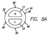
電極の数、および心臓ハーネスを形成しているパネルの数は、選択の問題である。例えば、一つの実施形態においては、心臓ハーネスは、2つの電極によって分離された2つのパネルを備えることができる。電極は、心臓の心外膜表面に最適な電気ショックを提供するために、好ましくは右心室あるいは左心室に隣接して電極を配置することができるように、180度離れてまたはいくつかの他の配向で配置される。他の実施形態においては、電極は、右心室に隣接する心筋を通って電気ショックが移動し、それによって除細動のための最適な電気ショックまたはペーシングのための周期的なショックを与えるように、180度離して配置することができる。他の実施形態においては、3本の電極によって分離された3つのパネルがあるように、3本の導線が心臓ハーネスに関連付けられる。 The number of electrodes and the number of panels forming the cardiac harness is a matter of choice. For example, in one embodiment, the cardiac harness can comprise two panels separated by two electrodes. The electrodes are preferably 180 degrees apart or some other so that the electrodes can be placed preferably adjacent to the right or left ventricle to provide optimal electrical shock to the epicardial surface of the heart. Are arranged in the orientation. In other embodiments, the electrode may cause an electrical shock to travel through the myocardium adjacent to the right ventricle, thereby providing an optimal electrical shock for defibrillation or a periodic shock for pacing. , 180 degrees apart. In other embodiments, three leads are associated with the cardiac harness so that there are three panels separated by three electrodes.
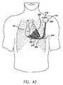
さらに他の実施形態においては、心臓ハーネス上の4つのパネルが4本の電極によって分離される。この実施形態においては、2つの電極が左心室に隣接して心臓の心外膜表面上あるいはその近傍に配置され、他の2つの電極が右左心室に隣接して心臓の心外膜表面上あるいはその近傍に配置される。電気ショックが供給されると、それは電極の2つの組の間で心筋を通過し、心室の全体にショックを与える。 In yet another embodiment, the four panels on the cardiac harness are separated by four electrodes. In this embodiment, two electrodes are positioned on or near the epicardial surface of the heart adjacent to the left ventricle and the other two electrodes are positioned on or near the epicardial surface of the heart adjacent to the right left ventricle. It is arranged in the vicinity. When an electrical shock is delivered, it passes through the myocardium between the two sets of electrodes and shocks the entire ventricle.
他の実施形態においては、心臓ハーネスを形成する4つ以上のパネルおよび4本以上の電極がある。電極およびパネルの配置は選択の問題である。さらに、1つ若しくは複数の電極を停止させることができる。 In other embodiments, there are four or more panels and four or more electrodes forming a cardiac harness. The placement of the electrodes and panels is a matter of choice. Furthermore, one or more electrodes can be stopped.
他の実施形態においては、心臓ハーネスが、複数のパネルを分離する複数の電極を備える。この実施形態はまた、心臓の機能を検知するとともに、両室ペーシング、左心室ペーシング、あるいは右心室ペーシングを含む再同期のためのペーシング刺激を供給する、1つ若しくは複数(多部位)のペーシング/検知電極を備える。 In other embodiments, a cardiac harness includes a plurality of electrodes that separate a plurality of panels. This embodiment also senses cardiac function and provides pacing stimulation for resynchronization including biventricular pacing, left ventricular pacing, or right ventricular pacing. A detection electrode is provided.
各実施形態において、除細動のための電気ショックまたは同期あるいはペーシングのための電気的なペーシング刺激がパルス発生器によって供給されるが、それには移植可能な電気的除細動器/除細動器(ICD)、心臓再同期治療除細動器(CRT-D)あるいはまたペースメーカーが含まれる。さらに、前述した各実施形態においては、心臓ハーネスは、心機能を制御するための多部位ペーシングを提供するべく、複数のペーシング/検知電極に接続することができる。多部位ペーシングを心臓ハーネスに組み込むことにより、このシステムは、収縮性機能不全を治療しつつ並行して徐脈および頻脈を治療するために用いることができる。このことは、送血量およびリズムを維持しつつ心室収縮シーケンスに変更を加えることによって、ポンプ機能を改善する。一つの実施形態においては、心臓ハーネスは、左右の心室の両方をぺーシングするために左右の心室に隣接して心臓の心外膜表面上に配置されたペーシング/検知電極を取り入れる。 In each embodiment, an electrical shock for defibrillation or an electrical pacing stimulus for synchronization or pacing is provided by a pulse generator, which includes an implantable cardioverter / defibrillator. This includes a device (ICD), a cardiac resynchronization therapy defibrillator (CRT-D) or a pacemaker. Further, in each of the previously described embodiments, the cardiac harness can be connected to multiple pacing / sensing electrodes to provide multi-site pacing for controlling cardiac function. By incorporating multi-site pacing into the cardiac harness, the system can be used to treat bradycardia and tachycardia in parallel while treating systolic dysfunction. This improves pump function by making changes to the ventricular contraction sequence while maintaining blood flow and rhythm. In one embodiment, the cardiac harness incorporates pacing / sensing electrodes positioned on the epicardial surface of the heart adjacent to the left and right ventricles to pace both the left and right ventricles.
他の実施形態においては、心臓ハーネスが、複数のパネルを分離する複数の電極を備える。この実施形態においては、少なくともいくつかの電極が、除細動のための電気ショックを提供するべく心臓の心外膜表面上にあるいはその近傍に配置される。そして他の電極は、左右の心室の同期、心臓再同期治療、両室ペーシング、左心室ペーシング、あるいは右心室ペーシングに有用なペーシング刺激を提供するために、心臓の心外膜表面上に配置される。 In other embodiments, a cardiac harness includes a plurality of electrodes that separate a plurality of panels. In this embodiment, at least some electrodes are placed on or near the epicardial surface of the heart to provide an electrical shock for defibrillation. And other electrodes are placed on the epicardial surface of the heart to provide pacing stimuli useful for left and right ventricular synchronization, cardiac resynchronization therapy, biventricular pacing, left ventricular pacing, or right ventricular pacing. The
他の実施形態においては、心臓ハーネスが、複数のパネルを分離する複数の電極を備える。少なくともいくつかの電極が除細動のための電気ショックを提供し、電極の1つ、単一部位電極が、単一の心室のペーシングおよび検知のために用いられる。例えば、単一部位電極が、左心室ペーシングあるいは右心室ペーシングのために用いられる。単一部位電極はまた、両室ペーシングを提供するために隔壁の近傍に配置することができる。 In other embodiments, a cardiac harness includes a plurality of electrodes that separate a plurality of panels. At least some of the electrodes provide an electrical shock for defibrillation and one of the electrodes, a single site electrode, is used for single ventricular pacing and sensing. For example, a single site electrode is used for left or right ventricular pacing. Single site electrodes can also be placed near the septum to provide bichamber pacing.
さらに他の実施形態において、心臓ハーネスは、ペーシング/検知機能を提供するために心臓ハーネスに取り付けられた1つ若しくは複数の電極を備える。この実施形態においては、単一部位電極は、左心室ペーシングのために左心室に隣接して心臓の心外膜表面上に配置される。あるいは、単一部位電極は、右心室ペーシングのために右心室に隣接して心臓の心外膜表面上に配置される。あるいは、複数のペーシング/検知電極が、両室ペーシングを含む両方の心室の同期性の治療のために、心臓の心外膜表面に配置される。 In yet other embodiments, the cardiac harness comprises one or more electrodes attached to the cardiac harness to provide pacing / sensing functionality. In this embodiment, a single site electrode is placed on the epicardial surface of the heart adjacent to the left ventricle for left ventricular pacing. Alternatively, a single site electrode is placed on the epicardial surface of the heart adjacent to the right ventricle for right ventricular pacing. Alternatively, multiple pacing / sensing electrodes are placed on the epicardial surface of the heart for the treatment of synchrony of both ventricles including biventricular pacing.
他の実施形態においては、心臓ハーネスが、複数のパネルを分離するコイルを備える。このコイルは高い柔軟性を有するが、心臓ハーネスを最小限に侵襲性なアクセスによって供給することができるように柱強度を提供することができる。 In other embodiments, a cardiac harness includes a coil that separates multiple panels. This coil is highly flexible, but can provide column strength so that the cardiac harness can be delivered with minimally invasive access.
さらに他の実施形態において、心臓を治療するためのシステムは、心臓の外側表面の近傍に配置される少なくとも一つの電極を具備した心臓ハーネスと、心臓の表面に取り付けられる少なくとも一つの心外膜導線とを備える。心外膜導線は、ねじ込み式の導線、あるいは心臓の表面上に縫合される導線とすることができるが、その両方が従来技術において周知である。また電力源を備え、この電力源は心臓ハーネスおよび心外膜導線の電極に接続される。電力源は、移植可能な電気除細動器/除細動器(ICD)、心臓同期治療除細動器(CRT-D)および/またはペースメーカーとすることができる。 In yet another embodiment, a system for treating a heart includes a cardiac harness comprising at least one electrode disposed near an outer surface of the heart and at least one epicardial lead attached to the surface of the heart. With. The epicardial lead can be a screwed lead or a lead that is sutured onto the surface of the heart, both of which are well known in the prior art. A power source is also provided, which is connected to the heart harness and the epicardial lead electrodes. The power source can be an implantable cardioverter / defibrillator (ICD), a cardiac synchronous therapy defibrillator (CRT-D) and / or a pacemaker.
この実施形態において、心外膜導線は低い電圧のペーシング/検知電極とすることができるが、心臓ハーネスに関連付けられている電極は高い電圧の細動除去電極とすることができる。他の実施形態において、心外膜導線は高い電圧の細動除去電極とすることができ、かつハーネスに関連避付けられている電極は低い電圧のペース/検知電極とすることができる。さらに他の実施形態においては、ペーシング/検知あるいは細動除去機能を実行するための唯一の電極が心外膜導線である。 In this embodiment, the epicardial lead can be a low voltage pacing / sensing electrode, while the electrode associated with the cardiac harness can be a high voltage defibrillation electrode. In other embodiments, the epicardial lead can be a high voltage defibrillation electrode and the electrode evacuated in connection with the harness can be a low voltage pace / sense electrode. In yet other embodiments, the only electrode for performing a pacing / sensing or defibrillation function is an epicardial lead.
他の実施形態において、心臓を治療するためのシステムは、少なくとも一つの電極を具備した心臓ハーネスと、心臓の少なくとも一つの室の内側に配設される少なくとも一つの経静脈的な導線とを備える。心臓ハーネスに関連付けられている電極は、細動除去電極とすることができるし、心臓にペーシング/検知の治療を施すこともできる。また、経静脈的な導線は、ペーシング/検知の治療を実施するための低い電圧の導線とすることができるし、細動除去のための高い電圧の導線とすることもできる。心臓の室の内側に挿入される低い電圧および高い電圧の導線を有することもまた予測される。電力源をさらに備え、この電力源は経静脈的な導線およびハーネスの電極に接続される。この電力源は、移植可能な電気除細動器/除細動器(ICD)、心臓再同期治療除細動器(CRT-D)、あるいはまたペースメーカーとすることができる。 In another embodiment, a system for treating a heart comprises a cardiac harness with at least one electrode and at least one transvenous lead disposed inside at least one chamber of the heart. . The electrode associated with the cardiac harness can be a defibrillation electrode or can provide pacing / sensing therapy to the heart. The transvenous lead can also be a low voltage lead for performing pacing / sensing therapy or a high voltage lead for defibrillation. It is also expected to have low and high voltage leads inserted inside the heart chamber. A power source is further provided, and the power source is connected to the transvenous leads and harness electrodes. This power source can be an implantable cardioverter / defibrillator (ICD), cardiac resynchronization therapy defibrillator (CRT-D), or also a pacemaker.
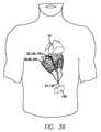
心臓ハーネスのあらゆる実施形態は、電極を有するものを含めて、例えば、剣状突起下、肋骨下、あるいは肋間切開、またカテーテルを用いた経皮的な供給による皮膚を介した心臓へのアクセスを含む最小限に侵襲性の方法を用いて、心臓上に供給しかつ移植するように構成される。 All embodiments of the cardiac harness, including those with electrodes, provide access to the heart through the skin by, for example, xiphoid, subcostal or intercostal incision, or percutaneous delivery using a catheter. It is configured to be delivered and implanted on the heart using minimally invasive methods including.
本発明は心臓病を治療するための方法および装置に関する。病んでいる心臓のリモデリングは、そのような心臓の壁応力を緩和することによって阻止することができ、あるいは逆転させることすらできることが期待される。本発明は、同一のシステムを用いつつ、心臓壁を支援するとともに除細動あるいはまたペーシングの機能を提供するための実施形態および方法を開示する。さらなる実施形態および態様は、出願人の係属中の出願である、2003年3月28日出願の米国出願第60/458,991号「マルチパネル心臓ハーネス」において議論されている。なお、その全ての内容がこの参照によって明白に組み込まれるものとする。 The present invention relates to a method and apparatus for treating heart disease. It is expected that remodeling of a diseased heart can be prevented or even reversed by relieving such heart wall stress. The present invention discloses embodiments and methods for supporting the heart wall and providing defibrillation and / or pacing functions while using the same system. Further embodiments and aspects are discussed in Applicant's pending application, US application Ser. No. 60 / 458,991, filed Mar. 28, 2003, “Multi-Panel Heart Harness”. All the contents are expressly incorporated by this reference.
先行技術の装置 Prior art equipment
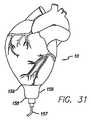
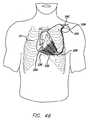
図1は、それに付加されるハーネス形態の従来技術心臓壁応力減少装置を有している哺乳類の心臓10である。このハーネスは、心臓の一部を取り囲んで右心室11、左心室12および尖端13を覆っている。参照の便宜上、軸線15は尖端および房室溝14を通過するものとする。この心臓ハーネスは、心臓に外接するとともに、壁体応力を緩和するために集合的に心臓上に緩やかな圧縮力を負荷する、一連のヒンジあるいはばね要素を有している。 FIG. 1 is a
本願明細書において用いる「心臓ハーネス」という用語は、患者の心臓上にフィットして心臓周期の少なくとも一部の間に心臓上に圧縮力を負荷する装置を指す、幅の広い用語である。 As used herein, the term “cardiac harness” is a broad term that refers to a device that fits on a patient's heart and applies a compressive force on the heart during at least a portion of the cardiac cycle.
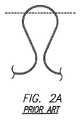
図1に示した心臓ハーネスは、心臓が充填の間に膨張するに連れて変形するように構成された、ヒンジあるいはばねヒンジと呼ばれる一連のばね要素を具備した、少なくとも一つの波形の素線を有している。各ヒンジは、一方向に作用するとともにその方向に対して垂直な方向には同じ程度の弾力性を提供しない、実質的に一方向の弾力性をもたらす。例えば、図2Aは弛緩した状態の従来技術のヒンジ部材を示している。このヒンジ部材は、中央部分および一対のアームを有している。図2Bに示したように、このアームが引っ張られると、曲げモーメントが中央部分に負荷される。この曲げモーメントは、弛緩した状態へとヒンジ部材を付勢する。一つの典型的な素線が一連のそのようなヒンジから構成されるとともに、これらのヒンジが素線の方向に弾性的に伸張しかつ収縮するように構成されていることに注目されたい。 The cardiac harness shown in FIG. 1 comprises at least one undulating strand with a series of spring elements, called hinges or spring hinges, configured to deform as the heart expands during filling. Have. Each hinge provides a substantially unidirectional elasticity that acts in one direction and does not provide the same degree of elasticity in a direction perpendicular to that direction. For example, FIG. 2A shows a prior art hinge member in a relaxed state. The hinge member has a central portion and a pair of arms. As shown in FIG. 2B, when the arm is pulled, a bending moment is applied to the central portion. This bending moment urges the hinge member to a relaxed state. Note that one typical strand is composed of a series of such hinges, and these hinges are configured to elastically expand and contract in the direction of the strand.
図1に示したハーネスにおいては、ばね要素の素線が、変形してばね要素を形成する押出加工されたワイヤから製作されている。 In the harness shown in FIG. 1, the strands of the spring elements are made from extruded wires that deform to form the spring elements.
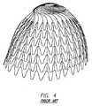
図3および図4は、そのようなハーネスを製造する間における2つの時点において示された、他の従来技術の心臓ハーネスを示している。このハーネスは、最初に、材料の比較的薄い、平坦なシート材料から成形される。平板からハーネスを成形するために、任意の方法を用いることができる。例えば、一つの実施形態においては、このハーネスは材料から光化学的にエッチングされ、他の実施形態においては、このハーネスは材料の薄板からレーザーカットされる。図3および図4に示したハーネスは、形状記憶特性を示す超弾性材料であるニチノールの薄板からエッチングしたものである。平坦なシート材料はひな型、金型等においてひだを付けられ、少なくとも心臓の一部の形を取るように成形される。 FIGS. 3 and 4 show other prior art cardiac harnesses shown at two points during the manufacture of such a harness. This harness is first molded from a relatively thin, flat sheet material of material. Any method can be used to form the harness from the flat plate. For example, in one embodiment, the harness is photochemically etched from the material, and in another embodiment, the harness is laser cut from a sheet of material. The harnesses shown in FIGS. 3 and 4 are etched from a thin plate of nitinol, which is a superelastic material exhibiting shape memory characteristics. The flat sheet material is pleated in a mold, mold or the like and shaped to take at least part of the heart.
さらに図1および図4を参照すると、この心臓ハーネスは、患者の心臓の底部領域に係合しかつフィットするように寸法決めされかつ構成された底部と、患者の心臓の尖端領域に係合しかつフィットするように寸法決めされかつ形付けられた尖端と、底部と尖端との間の中間部分とを有している。 With further reference to FIGS. 1 and 4, the cardiac harness engages a bottom sized and configured to engage and fit the bottom region of the patient's heart and the apical region of the patient's heart. And a tip sized and shaped to fit and an intermediate portion between the bottom and the tip.
図3および図4に示したハーネスにおいて、このハーネスは波形ワイヤーの素線あるいは列を有している。上述したように、この波形は、所望の方向において弾性的に屈曲可能なヒンジ/ばね要素を有している。いくつかの素線は、相互接続要素によって互いに接続されている。この相互接続要素は、素線の位置を互いに維持することを助けている。好ましくは、この相互接続要素は、隣接する素線の間においていくらかの相対運動を許容する。 In the harness shown in FIGS. 3 and 4, the harness has a wire or a row of corrugated wires. As described above, this corrugation has a hinge / spring element that is elastically bendable in a desired direction. Some strands are connected to each other by interconnection elements. This interconnection element helps maintain the position of the strands relative to each other. Preferably, this interconnection element allows some relative movement between adjacent strands.
波形のばね要素は、心臓の膨張に対して抵抗する力を作用させる。集合的にばね要素が発揮する力は心臓を圧縮する役割を果たし、心臓が膨張するときに心臓壁の応力を緩和する。したがって、このハーネスは心臓の作業負荷の減少を助けて、心臓がより効果的に血液をポンプ送りして患者の身体に行き渡らせることを可能にし、かつ心臓それ自体が回復する機会を与える。ここで理解されるべきことは、壁体応力を減少させるべく心臓上に穏やかな圧縮力を生み出すために、ばね部材のいくつかの配置および構造を用い得ることである。例えば、心臓の外周の一部分のみの上にばね部材を配設することもできるし、ばね部材は心臓のかなりの部分を覆うこともできる。 The corrugated spring element exerts a force that resists heart expansion. The forces exerted by the spring elements collectively serve to compress the heart and relieve stress on the heart wall as the heart expands. This harness thus helps reduce the workload on the heart, allows the heart to pump blood more effectively and spread across the patient's body, and provides an opportunity for the heart itself to recover. It should be understood that several arrangements and configurations of spring members can be used to create a gentle compressive force on the heart to reduce wall stress. For example, the spring member can be disposed on only a portion of the outer periphery of the heart, or the spring member can cover a substantial portion of the heart.
心臓は拡張期と収縮期の間に膨張しかつ収縮するに連れて、心筋の収縮細胞が膨張し収縮する。病んでいる心臓において、心筋は、細胞が弱って少なくともいくらか収縮性を失うように膨張し得る。弱った細胞は、膨張および収縮の応力を処理する能力が小さい。このようにして、心臓のポンプ送りの効率が減少する。上記の心臓ハーネスの実施形態におけるばねヒンジの各列は、心臓が拡張期の間に膨張するに連れてばねヒンジが対応して伸張し、それによってばねの曲げエネルギーとして膨張力を貯えるように構成されている。このように、心筋上の応力負荷はハーネスによって部分的に取り除かれる。応力のこのような減少は、心筋細胞が健康なままであること、および/または健康を取り戻すことを助ける。心臓が収縮期の間に収縮すると、開示した従来技術の心臓ハーネスは、膨張の間に生じた曲げエネルギーをヒンジあるいはばね要素が放出して適度な圧縮力を負荷するので、心臓が収縮するときに心臓ハーネスが心臓に追従するようにしつつ、収縮力を負荷する。 As the heart expands and contracts between diastole and systole, the contractile cells of the myocardium expand and contract. In a diseased heart, the myocardium can swell so that the cells weaken and lose at least some contractility. Weakened cells are less capable of handling expansion and contraction stresses. In this way, the efficiency of heart pumping is reduced. Each row of spring hinges in the cardiac harness embodiment described above is configured such that the spring hinges correspondingly expand as the heart expands during diastole, thereby storing the expansion force as spring bending energy. Has been. In this way, the stress load on the myocardium is partially removed by the harness. Such a reduction in stress helps the cardiomyocytes remain healthy and / or regain health. When the heart contracts during systole, the disclosed prior art heart harness releases the bending energy produced during expansion and the hinge or spring element applies a moderate compressive force so that the heart contracts. The contraction force is applied while the heart harness follows the heart.
心臓ハーネスのための他の構造的な配置が存在するが、それらの全てが欠点を有しており、かつCHFおよび他の関連する疾患あるいは不全を治療するべく最適には機能しない。本発明の心臓ハーネスは、CHFを治療するための斬新な方法を提供するとともに、除細動のため、あるいは再同期のためのペーシング刺激のため、または両方の心室のペーシング/検知のための、ハーネスに関連付けられて電気的なショックを与える電極を提供する。 There are other structural arrangements for cardiac harnesses, but all of them have drawbacks and do not function optimally to treat CHF and other related diseases or disorders. The cardiac harness of the present invention provides a novel method for treating CHF, and for pacing stimulation for defibrillation or resynchronization, or for pacing / sensing of both ventricles. An electrode for providing an electrical shock associated with a harness is provided.
実施形態 Embodiment
本発明は、心臓を治療するための心臓ハーネスシステムに向けられている。本発明の心臓ハーネスシステムは、心臓を治療するための心臓ハーネスを心臓リズム管理装置に結びつける。より詳しくは、この心臓ハーネスは、心臓の壁体応力圧力を軽減するために拡張期および収縮期の間に心臓上に圧縮力を与える、ばね要素の列あるいは波形の素線を有している。心臓ハーネスに関連付けられているものは、様々な理由のうち特に鬱血性心不全による心拍動の多くの不規則さを治療するための心臓リズム管理装置である。これにより、心臓ハーネスに関連付けられている心臓リズム管理装置は、1つ若しくは複数の、付随する導線および電極を有した移植可能な電気除細動器/除細動器と、心機能を検知するとともに両方の心室の同期性を治療するペーシング刺激を与えるために用いられる、導線および電極を含む心臓ペースメーカと、除細動ショックあるいはまたペーシング/検知機能をもたらすための、付随する導線および電極を有する、統合された移植可能な電気除細動器/除細動器およびペースメーカーと、を備える。 The present invention is directed to a cardiac harness system for treating the heart. The cardiac harness system of the present invention combines a cardiac harness for treating the heart with a cardiac rhythm management device. More particularly, the cardiac harness has a row of spring elements or corrugated strands that provide a compressive force on the heart during diastole and systole to relieve heart wall stress pressure. . Associated with the cardiac harness is a cardiac rhythm management device for treating many irregularities of heartbeat due to congestive heart failure, among other reasons. Thereby, the cardiac rhythm management device associated with the cardiac harness senses cardiac function with an implantable cardioverter / defibrillator with one or more associated leads and electrodes. And a cardiac pacemaker, including leads and electrodes, used to provide pacing stimuli to treat the synchrony of both ventricles, and associated leads and electrodes to provide defibrillation shocks or also pacing / sensing functions An integrated implantable cardioverter / defibrillator and pacemaker.
この心臓ハーネスシステムは、少なくとも部分的に心臓を取り囲むとともに拡張期および収縮期の間に心臓を援助するために互いに接続されるパネルの、様々な配置を有している。この心臓ハーネスシステムはまた、心臓ハーネスおよび除細動ショックあるいはペーシング刺激を供給するべく電極に供給される電力の供給源に関連付けられた、電極を具備する1つ若しくは複数の導線を有している。 The cardiac harness system has various arrangements of panels that at least partially surround the heart and that are connected together to assist the heart during diastole and systole. The cardiac harness system also includes one or more leads comprising electrodes associated with the cardiac harness and a source of power supplied to the electrodes to deliver a defibrillation shock or pacing stimulus. .
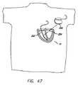
本発明の一実施形態においては、図5に平坦な状態で示すように、心臓ハーネス20は、概ね連続している波形の素線22の2つのパネル21を有している。パネルは、互いに接続されるとともに一対の電極の間の配置された、ヒンジ若しくはばね要素の列あるいは波形の素線を有しており、この列あるいは波形は円周方向には非常に弾性的であるが、長手方向においてはその程度は小さい。この実施形態においては、波形の素線は、方向線24に沿って円周方向に伸張しかつ収縮できるU字形のヒンジあるいはばね要素23を有している。この心臓ハーネスは、ベース部あるいは上端部25、および先端部あるいは下端部26を有している。波形の素線は、心臓10の周りに配置されたときに、円周方向には非常に弾力的であるが、心臓の軸線15と平行な方向においてはその程度は小さい。同様のヒンジあるいはばね要素は、係属中でありかつ同時に譲渡された2003年3月28日出願の米国出願第60/458,991号に開示されている。なお、その内容の全ては、この参照によって本願明細書に引用したものとする。図5の実施形態は、参照を容易にするために平坦に見えるが、使用の際には心臓に従うために実質的に円筒状(あるいはテーパ状)であり、かつ右側および左側のサイドパネルは実際には単一のパネルであって、波形の素線には不連続性はない。 In one embodiment of the present invention, as shown in a flat state in FIG. 5, the
波形の素線22は心臓の心外膜表面上に圧縮力をもたらし、それによって壁体応力を軽減する。特に、ばね要素23は、拡張および収縮の機能の間に心臓が膨張しかつ収縮するに連れて、円周方向に伸張しかつ収縮する。心臓が膨張すると、ばね要素は、拡がって膨張力を貯え続けるので、伸張しつつ膨張を妨げる。収縮期の間に、心臓10が収縮すると、ばね要素は貯えた曲げ力を放出することにより円周方向に収縮し、それによって拡張および収縮の両方の機能を助ける。 The
まさに議論したように、曲げ応力は拡張期の間にばね要素23によって吸収され、かつ曲げエネルギーとしてばね要素に貯えられる。収縮期の間に、心臓がポンプ送りすると、心筋が収縮して心臓はより小さくなる。同時に、ばね要素23に貯えられた曲げエネルギーは少なくとも部分的に放出され、それによって収縮期の間の心臓に支援をもたらす。好ましい実施形態においては、ハーネスのばね要素によって心臓に負荷される圧縮力は、収縮期の間に心臓が収縮する際に実行される機械的な仕事量の約10%〜15%である。このハーネスは、心室のポンピングに取って代わることは意図されていないが、収縮期の間に実質的に心臓を援助する。 As just discussed, the bending stress is absorbed by the
波形の素線22は、ばね要素の振幅およびピッチに応じて、異なる数のばね要素23を有することができる。例えば、ばね要素の振幅あるいはピッチを変更することにより、パネル1枚あたりの波形の数もまた同様に変化する。心臓ハーネス20が心臓の心外膜表面に与える圧縮力の量を増大することが望まれる場合に、本発明は、より小さい振幅およびより短いピッチを具備したばね要素を有するパネルを提供し、それによってばね要素が作用させる伸張力を増大させる。言い換えると、他の全ての要素が一定であると、相対的により小さい振幅を具備する要素はより堅いものとなって拡がりに抵抗し、それによって拡張期の間により多くの曲げ力を貯える。さらに、ピッチがより小さいと、波形の素線に沿った単位長さあたりのばね要素がより多くなるので、それによって拡張期の間に貯えられて収縮期の間に放出される全体的な曲げ力が増大する。心臓ハーネスによって心臓の心外膜表面上に与えられる圧縮力に影響を及ぼす他の要素には、ばね要素の形状、波形の素線を成形しているワイヤの直径と形状、および素線を構成する材料が含まれる。
図5に示したように、波形の素線22は、グリップパッド27によって互いに接続されている。図5に示した実施形態においては、隣接する波形の素線は、ばね要素23の尖端28に取り付けられた1つ若しくは複数のグリップパッドによって接続されている。隣接する波形の素線の間のグリップパッドの数は選択の問題であり、隣接する波形の素線の間にグリップパッドが一つの状態と、波形の素線の全ての尖端にグリップパッドがある状態との間で変更することができる。重要なことは、グリップパッドが、重なりを防止してグリップパッドと心臓の心外膜表面との間の摩擦係合を高めるべく、隣接する波形の素線の間の隙間を維持するという目的を犠牲にすることなしに心臓ハーネス20の柔軟性を維持するために配置されるべきであるということである。さらに、ばね要素の尖端にグリップパッドを取り付けることが望ましいが、本発明はそれには限定されない。グリップパッド27は、側部29を含む、ばね要素の長手方向に沿った任意の箇所に取り付けることができる。さらに、グリップパッド27の形状は、図5に示したように、特定の目的に合わせて変化させることができる。例えば、グリップパッド27は、一つの波形の素線22の尖端28に取り付けるとともに、隣接する波形の素線の2つの尖端に取り付けることができる(図7を参照)。図5に示したように、全ての頂点が互いに対向していると、それらは「位相がずれている」と呼ばれる。波動の尖端が位置合わせされていると、それらは「位相が合っている」と呼ばれる。各波形の素線のばね要素の数が同じであるから、全ての尖端は位相がずれている。しかしながら、その上部の近傍のベース部から底部におけるその尖端13へと心臓がテーパ状であるから、各波形の素線のばね要素の数が異なり得ることは、本発明が意図するところである。したがって、心臓ハーネスの上部あるいはベースにおいては、心臓の尖端近傍にある心臓ハーネスの底部におけるよりも、より多くのばね要素およびパネル一枚につきより長い波形の素線がある。したがって、心臓ハーネスは、相対的に広いベースから相対的に細い底部へと、心臓の尖端に向かってテーパ状である。このことは、ばね要素の頂点の配列、したがってグリップパッド27の完全に位置合わせする機能、およびばね要素の隣接する頂点に取り付く機能に影響を及ぼす。波形の素線およびグリップパッドの形態のアタッチメント手段に関する更なる開示および実施形態は、係属中でありかつ同時に譲渡された、2003年7月10日に出願の米国特許出願第60/486,062号に見出される。なお、その内容の全ては、この参照によって本願明細書に引用したものとする。隣接する波形の素線22の間の接続は好ましくはグリップパッド27であるが、他の実施形態(図示せず)においては、波形の素線が素線と同じ材料から製造された相互接続要素によって接続される。これらの相互接続要素は、共通に所有されている米国特許第6,612,979 B2の図8A〜図8Bに示すように、真直あるいは曲線とすることができる。なお、その内容の全ては、この参照によって本願明細書に組み込まれたものとする。 As shown in FIG. 5, the
波形の素線22が、図5に示したように連続していることが好ましい。例えば、隣接する波形の素線のすべての組が棒状アーム30によって接続される。棒アームは、湾曲して波形の素線を形成するとともにこの棒アームに沿ってその終端が溶接される連続したワイヤの一部を形成するが好ましい。この溶接は、図5には示されていないが、レーザ溶接、溶着、あるいは従来通りの溶接といった、任意の従来技術によってなすことができる。波形の素線を形成するために用いるワイヤの種類は、波形の素線を形成するために用いるワイヤの終端を取り付ける方法に関連している。例えば、波形の素線は、従来の溶接の間に高い熱にさらされるとその超弾性あるいは形状記憶特性のいくらかを失い得るニチノールのような、ニッケル−チタン合金から作ることが好ましい。 The
本発明の心臓ハーネスに関連付けられているものは、先に開示したような心臓リズム管理装置である。これにより、図5に示した心臓ハーネスに関連付けられているものは、細動ショックを与えるために用いられる1つ若しくは複数の電極である。以下において直ぐに判るように、鬱血性心不全に関連する多くの要因は、患者の生命を救うために即時の処置を必要とする細動につながり得る。 Associated with the cardiac harness of the present invention is a cardiac rhythm management device as previously disclosed. Thus, what is associated with the cardiac harness shown in FIG. 5 is one or more electrodes used to deliver a fibrillation shock. As will be seen immediately below, many factors associated with congestive heart failure can lead to fibrillation requiring immediate treatment to save the patient's life.
病んでいる心臓は、多くの場合いくつかの疾病を有している。珍しくない一つの疾病は、心臓の電気的刺激システムの不規則性によって生じる心拍動の不規則さである。例えば、心筋梗塞によるダメージは、心臓の電気信号を中断させることができる。いくつかの場合には、ペースメーカのような移植可能な装置が、心臓リズムの制御を助け心臓のポンプ送りを刺激する。心臓の電気系統の問題は、時には心臓に細動を生じさせ得る。細動の間、心臓は正常に鼓動せず、時には十分なポンプ送りを実行しない。除細動器は、心臓を正常な鼓動に復帰させるために用いることができる。体外式除細動器は、典型的に、患者の胸部に付加される一対の電極パドルを有している。この除細動器は、電極の間に電界を発生させる。電流が患者の心臓を通過して心臓の電気系統を刺激し、心臓が規則正しいポンピングに回復することを助ける。 A sick heart often has several diseases. One disease that is not uncommon is irregular heartbeats caused by irregularities in the heart's electrical stimulation system. For example, damage due to myocardial infarction can interrupt the electrical signal of the heart. In some cases, an implantable device such as a pacemaker helps control the heart rhythm and stimulates heart pumping. Problems with the heart's electrical system can sometimes cause fibrillation in the heart. During fibrillation, the heart does not beat normally and sometimes does not perform enough pumping. A defibrillator can be used to return the heart to a normal heartbeat. An external defibrillator typically has a pair of electrode paddles added to the patient's chest. This defibrillator generates an electric field between the electrodes. The current passes through the patient's heart and stimulates the heart's electrical system, helping the heart to recover to regular pumping.
時には、患者の心臓は、心臓手術あるいは他の胸部開放手術の間に細動し始める。このような場合には、特別なタイプの除細動装置が用いられる。胸部開放除細動器は、心臓の両側において心臓に付加できるように構成された、特別な電極パドルを有している。強い電界がパドルの間に作り出され、電流が心臓を通過して心臓に除細動処置を施し、心臓を規則正しいポンピングに回復させる。 Sometimes the patient's heart begins to fibrillate during cardiac surgery or other open chest surgery. In such cases, a special type of defibrillator is used. An open chest defibrillator has special electrode paddles configured to be added to the heart on both sides of the heart. A strong electric field is created during the paddle, and current passes through the heart to defibrillate it and restore the heart to regular pumping.
特に細動に敏感ないくらかの患者においては、移植可能な心臓除細動装置を用いることができる。典型的に、移植可能な心臓除細動装置には、移植可能な心臓除細動器(ICD)、あるいは通常は右心室に置かれる一つの電極だけを有してリターン電極が除細動器ハウジングそれ自身である、典型的に胸部に植設される心臓再同期治療装置(CRT-D)が含まれる。あるいは、移植可能な装置は、心臓壁に直接、内側あるいはその近傍に取り付けられる二個以上の電極を有している。患者の心臓が細動し始めると、これらの電極は、上述した他の除細動器と同様にそれらの間に電界を発生させる。 In some patients who are not particularly sensitive to fibrillation, an implantable cardiac defibrillator can be used. Typically, an implantable cardiac defibrillator device has an implantable cardiac defibrillator (ICD) or defibrillator with a return electrode having only one electrode normally placed in the right ventricle. The housing itself is typically a cardiac resynchronization therapy device (CRT-D) implanted in the chest. Alternatively, the implantable device has two or more electrodes attached directly to or near the heart wall. When the patient's heart begins to fibrillate, these electrodes generate an electric field between them, similar to the other defibrillators described above.
試験が示したところでは、導電性材料から製造された装置によって取り囲まれている心臓の外側に除細動処置を施す電極が取り付けられると、この電極によって分配された電流の少なくともいくらかが、心臓を通るのではなくて、導電材料によって心臓の周り導かれる。これにより、除細動の有効性が減少することになる。したがって、本発明は心臓の除細動を可能にするいくつかの心臓ハーネスの実施形態を含み、かつ他の実施形態は除細動処置、再同期、左心室ペーシング、右心室ペーシング、および両室ペーシング/センシングのための手段を開示する。 Tests have shown that when an electrode for defibrillation is attached to the outside of the heart surrounded by a device made from a conductive material, at least some of the current delivered by this electrode will cause the heart to Instead of passing, it is guided around the heart by a conductive material. This reduces the effectiveness of defibrillation. Accordingly, the present invention includes several cardiac harness embodiments that allow cardiac defibrillation, and other embodiments include defibrillation procedures, resynchronization, left ventricular pacing, right ventricular pacing, and biventricular chambers. A means for pacing / sensing is disclosed.
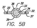
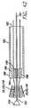
さらに本発明によると、心臓ハーネス20は、間隔を開けて配置されるとともにパネル21を分離している導電性の電極部分32を有した、一対の導線31を有している。図5に示したように、電極は、非導電性部材34で包まれた導電性のコイルワイヤ33から、好ましくは螺旋形に形成されている。導電性ワイヤ35は、このコイルワイヤにおよび電力源36に取り付けられている。本明細書において用いる、電力源36は、電極の特定な用途に応じて、パルス発生器、移植可能な電気的除細動器/除細動器、ペースメーカー、およびペースメーカに接続された移植可能な電気的除細動器/除細動器を含むことができる。図5に示した実施形態において、電極は、電気的なショックが心筋を通過するように、導電性ワイヤおよび電力供給源を介して心臓の心外膜表面に電気的なショックを供給するように構成されている。図示した実施形態においては、それらが心臓の外周の周りに約180度間隔を開けるように、電極が間隔を開けて配置されているが、それには限定されない。言い換えると、電極は、それらが45度、60度、90度、120度、あるいは任意の円弧長さだけ離れて、または、その点に関しては、適切な電気的なショックを供給するために心臓の外周の周りにおいて本質的に任意の円弧長さだけ間隔を開けて配置することができる。前述したように、心臓に除細動処置を施すことが必要になり得るし、心臓に除細動処置を施すために適した電気的ショックを供給するように電極32が構成される。 Further in accordance with the present invention, the
なおも図5を参照すると、電極32は心臓ハーネス20、より詳しくは絶縁材料37によって波形の素線22に取り付けられている。絶縁材料は、電流が電極からハーネスへと通過し、それによって除細動のための電流が望ましくなく心臓からそれることがないように、心臓ハーネスから電極を絶縁している。好ましくは、絶縁材料は、波形の素線22を覆うとともに電極32の少なくとも一部を覆っている。図5の実施形態においては、中央のパネルの波形の素線が絶縁材料によって覆われているが、右側および左側のパネルは裸の金属部分である。パネルの波形の素線の全てが絶縁材料で被覆され、それによって電極によって供給される電気的なショックからハーネスを絶縁することが好ましいが、波形の素線の一部あるいは全てを、除細動のためにあるいはペーシングのために心臓の心外膜表面への電気的なショックの供給に用いられる、裸の金属部分とすることができる。 Still referring to FIG. 5, the
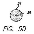
より詳しく後述するように、電極32は、心臓の心外膜表面の近傍にあるいは直接的に接触することが意図されている導電性の第1の放電表面38と、第1の表面の反対側で心臓表面から離れて対向する導電性の第2の放電表面39とを有している。本明細書において用いる「近傍に」という用語は、電極が心臓の心外膜表面のような外側表面の近傍にあるい直接的に接触して配置されることを意味することが意図されている。第1の表面および第2の表面は、典型的に、裸の金属製導電コイルが移植可能な電気除細動器/除細動器(ICDあるいはCRT-D)36のような電力供給源(パルス発生器)から心臓の心外膜表面へと電流を導電することができるように、絶縁材料37によって覆われない。他の実施形態においては、一つの表面だけを介して選択的に電流を導くために、第1あるいは第2の表面のいずれかを絶縁材料によって覆うことができる。構造の更なる細部および本発明の導線31および電極33の使用は、心臓ハーネスと共に、本願明細書においてより充分に説明する。 As will be described in more detail below, the
重要なことは、電極32を波形の素線22に取り付けるために用いられているこの絶縁材料37が、電極の導電性金属コイル33を介して放電されるいかなる電流からも波形の素線を絶縁することである。さらに、本実施形態における絶縁材料は柔軟であり、最小限に侵襲性なの供給のためにより小さな輪郭へと心臓ハーネス20を折り重ねるときに、電極が継目あるいはヒンジの役割を果たすことができるようになっている。したがって、さらに詳細に説明するように(図13および図14を参照)、この心臓ハーネスは、肋間を介した供給、例えば肋骨郭、あるいは心臓にアクセスするために最小限に侵襲性の手術において典型的に用いられる他の領域を介した供給のために、その輪郭を縮小させるべく、電極の長手方向に沿って、その全長方向に折り重ねることができる。典型的に心臓を含む最小限に侵襲性のアプローチは、剣状突起下、肋骨下、あるいは肋間を切開することによってなされる。心臓ハーネスは、折り重ねられると、円形あるいは概ね楕円形の形状に縮小するが、その両方が最小限に侵襲性な手技を助長する。 Importantly, this insulating
さらに本発明によると、導線31および電極32の断面が図5B、図5Cおよび図5Dに示されている。図5Bに示したように、電極32は、非電導性部材34の周りに螺旋形のパターンで巻き付けられた、コイルワイヤ33を有している。絶縁材料37は、波形の素線22の端部において電極と棒状アーム30との間に、隙間を開けた接続をもたらしている。電極は、棒アームあるいは波形の素線のいかなる部分にも、接触しあるいは重なることがない。その代わりに、絶縁材料は、電極と波形の素線の棒状アームとの間に取付手段を提供している。これにより、この絶縁材料37は、絶縁性の非導電性材料として作用するばかりでなく、波形の素線と電極との間に取付け手段を提供する。絶縁材料37は、取付箇所において比較的薄いので、非常に柔軟であるとともに電極が心臓ハーネスパネル21と共に柔軟であるようにし、前述したように心臓が鼓動するに連れて膨張しかつ収縮する。 Further in accordance with the present invention, cross sections of the conductor 31 and
図5Cを参照すると、非導電性部材34は、コイルワイヤ33を越えて距離を開けて延びている。非導電性部材は、好ましくは絶縁材料37と同じ材料、典型的にシリコンゴムあるいは類似した材料から作られる。絶縁材料は、シリコンゴムあるいは類似の材料から作られることが好ましいが、パリレン(登録商標)(UnionCarbide)、ポリウレタン、ポリテトラフルオルエチレン、テトラフルオロエチレンおよびePTFEから作ることもできる。明らかなように、この非導電性部材は、素線を電極32に接続するべく、波形の素線22の棒状アーム30に絶縁材料を取り付けるため支持をもたらしている。導電性ワイヤ35を介して電力源36から電流が供給されたときに電極コイル33が通電されるように、導電性ワイヤ35は非導電性部材を通って延びてコイルワイヤ33の近位端に取り付けられている。この導電性ワイヤ35もまた非導電性材料34によって覆われている。図5Dを参照すると、非導電性部材34が心臓ハーネスの底部(尖端)を越えて延び続けるとともに、導電性ワイヤ35が非導電性部材から延び出て電力源36へと延びていることがわかる。図5B〜図5Dに図示されている実施形態においては、心臓ハーネスは、除細動あるいはペーシング機能の間に電極によって供給される電気ショックの電流が心臓ハーネス20によって短絡しないように、絶縁材料37によって電極から保護されている。 Referring to FIG. 5C, the
心臓ハーネス20は、ニチノールのような超弾性あるいは形状記憶材料である固体ワイヤ部材で作られた波形の素線22から構成されるとともに、電極32から絶縁されることが好ましいが、心臓の心外膜表面に電気ショックを供給するために波形の素線のいくつかあるいはその全てを用いることも可能である。例えば、図6Aに示したように、波形の素線22を形成するために、かつ重要なことには心臓の心外膜表面に電気ショックを供給するために効果的に電流を伝達するために、複合ワイヤ45を用いることができる。この複合ワイヤ45は、例えば銀(Ag)から形成されてニチノール製のチューブ46によって覆われた、導電性のワイヤ47を含んでいる。外側のニチノール製チューブ46の表面導電度を高めるために、きわめて導電性の高いコーティングがニチノール製チューブ上に配設される。例えば、ニチノールチューブは、プラチナ(Pt)、あるいはプラチナイリジウム(Pt-Ir)、または酸化イリジウム(IROX)を含む同等な材料の蒸着層によって覆うことができる。このように製作された複合ワイヤは、ニチノールチューブに起因して伸張し収縮する優れた機械的な性能を有するとともに、電流を導くワイヤ47から生じる高められた電気的な性質、およびプラチナイリジウムの表面層を介して高められた電解/電気化学的な特性を有する。したがって、波形の素線22のいくらかの部分あるいはその全てを複合ワイヤ45から製作すると、心臓ハーネス20は、波形の素線を介して心臓の選択した部分上に除細動ショックを供給することができるとともに、前述したように圧縮力を与えるべく機能する。 The
図6Aにおける導電性の波形の素線とは対照的に、断面図6Bに示したような非導電性の絶縁された波形の素線22が存在する。前述したように、心臓の心外膜表面上の電気ショックを供給するときに電極を介して供給される電流から素線を絶縁するために、波形の素線22の一部あるいは全てを絶縁材料37によって覆うことができる。したがって、図6Bに示したように、電極32によって供給される電気ショックに対する絶縁をもたらすために、波形の素線22は絶縁材料37によって覆われているが、柔軟性および波形の素線の伸張的な特性は維持している。 In contrast to the conductive corrugated strands in FIG. 6A, there is a non-conductive insulated
本発明の重要な観点は、最小限に侵襲的に植設することができるとともに、縫合糸、クリップ、ネジ、接着剤あるいは他の取付手段を必要とすることなしに心臓の心外膜表面に取り付ることができる、心臓ハーネス20を提供することにある。重要なことは、波形の素線22が、その断面形状に応じて、心外膜表面に対し比較的高い摩擦係合を与え得ることである。例えば、図6Cに開示した実施形態において、波形の素線22の断面形状は、円形、矩形、三角形、あるいはその事を言うなら波形の素線と心臓の心外膜表面との間の摩擦係合を増大させる任意の形状とすることができる。図6Cに示したように、(高いのではなく)平らな矩形表面を有している中間の断面形状は、心臓ハーネスの最小限に侵襲性の供給を高めるための低い輪郭を有しているばかりでなく、心外膜に係合しかつ突き刺さる傾向を有して心臓の心外膜表面に対する摩擦係合を増大させる矩形の縁部を有している。高い摩擦係合性を有したグリップパッド27に接続されている、波形の素線の適切な断面形状により、心臓ハーネスを心臓の心外膜表面に取り付けるための縫合、クリップ止めあるいは他の取付手段は不要となる。 An important aspect of the present invention is that it can be implanted minimally invasively and on the epicardial surface of the heart without the need for sutures, clips, screws, adhesives or other attachment means. It is to provide a
図7Aおよび図7Bに示した他の実施形態においては、図5の実施形態に比較すると、心臓ハーネス20のための異なる構造および電極32が示されている。図7Aおよび図7Bにおいては、3つの電極が、電極の間で延びている波形の素線22を有した3枚のパネル21を分離していることが示されている。前述した実施形態と同様に、拡張および収縮の機能の間に波形の素線が伸張しかつ収縮し、かつ両方の機能の間に圧縮力を負荷することができるように、ばね要素23は波形の素線から形成されている。図7Aの向こう側は、明快さのために示されていない。心臓の外周における電極の位置は選択の問題であり、図7Aの実施形態においては、電極は120度で等しい間隔を開けることができる。それとは別に、右心室を通してより多くの電気ショックを供給することが重要であり、左心室よりも右心室に接近させて電極を位置決めすることが必要である。同様に、右心室とは反対に左心室に電気ショックを供給することがさらに重要である。従って、電極の位置ぎめは、他の実施形態と同様に選択の問題である。 In other embodiments shown in FIGS. 7A and 7B, different structures and
さらに図7Aおよび図7Bを参照すると、この実施形態においては、電極によって供給される電気ショックが、心尖13により近い心臓の下側部分を含めて心臓の心外膜表面に供給されることを確実なものとするために、電極32は心臓ハーネス20の底部あるいは尖端部を越えて延びている。したがって、電極22は遠位端50および近位端51を有しており、その近位端が心尖13により接近し配置され、かつその遠位端が心臓のベースあるいは上側部分により接近して配置されている。本明細書において、遠位側とは人体に入り込むとともに担当医から離れることを意味し、かつ近位側とは人体の外側により接近しかつ担当医により接近することを意味することが意図されている。電極の近位端は心尖により接近して配置され、心尖により接近させて電気ショックを供給する能力を含むいくつかの機能を提供する。電極の近位端はまた、心臓ハーネス20およびパネル21のための支持を提供するべく機能し、(本願明細書において後に説明するような)供給の間だけではなく、滑ることなしに心臓上にハーネスを保持するべくパネルを分離して心臓の心外膜表面を握持する際にも、支持を与える。 Still referring to FIGS. 7A and 7B, in this embodiment it is ensured that the electrical shock delivered by the electrodes is delivered to the epicardial surface of the heart, including the lower part of the heart closer to the apex 13. For this purpose, the
図7Aおよび図7Bの実施形態は、心臓ハーネス20の3枚のパネル21を分離する電極32を示しているが、個々の適用に合わせてより多くあるいはより少ない電極およびパネルを設けることができる。例えば、好ましい一実施形態においては、4つの電極32が4枚のパネル21を分離し、2つの電極を左心室と対向する側に配置し、2つの電極を右心室と対向する側に配置することができる。この実施形態においては、好ましくは4つの電極のすべてが用いられ、右心室と対向する側の2つの電極の第1の組が1つの(共通する)電極として作動し、左心室に対向する側の2つの電極の第2の組が反対側の(共通する)電極として作動する。あるいは、2つの電極が作動し、他の2つの電極は必要とされない限り作動しないダミー電極とすることができる。 Although the embodiment of FIGS. 7A and 7B shows an
現在、商業的に入手できる、移植可能な電気的除細動器/除細動器(ICD)は、心臓に除細動処置を施すために約30〜40ジュールを供給することができる。本発明については、本発明の心臓ハーネス20の電極22が30〜40ジュール未満の除細動ショックを供給することが好ましい。商業的に入手可能なICDは、30〜40ジュール未満の電力を供給する電極を有した本発明の心臓ハーネスシステムに合わせて、より低いパワーレべルを提供するように改良することができる。一般に、電極構造の1つの目的は、心筋の全体にわたって一様な電流密度分布を生み出すことにある。したがって、使用する電極の数に加えて、サイズ、形状および相対位置のすべてが誘起される電流の密度分布に影響を与える。したがって、1〜4つの電極が本発明の好ましい実施形態であるが、5〜8つの電極もまた想像し得る。 Currently, commercially available implantable cardioverter / defibrillators (ICDs) can deliver about 30-40 joules for performing defibrillation procedures on the heart. For the present invention, it is preferred that the
本発明によれば、心臓ハーネスおよび関連する心臓リズム管理装置は、除細動ショックを提供するためだけに用いるのではなく、両方の心室の同期性の治療、再同期療法、両室ペーシング、および左心室のペーシングあるいは右心室ペーシングのためのペーシング/検知器として用いることができる。図8A〜図8Dに示したように、心臓10は、右心室11および左心室12を露出するために断面図として示されている。心臓ハーネス20は、心臓の外側表面のまわりに、好ましくは心臓の心外膜表面上に取り付けられており、かつ多数の電極がこの心臓ハーネスに関連付けられている。より詳しくは、電極32は心臓ハーネスに取り付けられ、かつ右心室および左心室と対向する側において心臓の外周に配置されている。万一細動が生じたときに、この電極は、心臓に除細動処置を施すために、心筋および左右の心室を介して電気ショックを与える。さらに心臓ハーネス上に取り付けられているものは、心臓をモニタしてペースメーカーにデータを提供するように機能する、ぺーシング/検知用の導線40である。必要とされる場合、このペースメーカーは、心室を同期させるためにペーシング刺激を与え、あるいはまた左心室ペーシング、右心室ペーシング、または両室ペーシングを与える。したがって、例えば図8Cにおいては、ぺーシング/検知用の導線40の組が左右の心室の自由な壁に隣接して配置され、かつ心室を同期させるべくペーシング刺激を与えるために、または左心室ペーシング、右心室ペーシング、あるいは両室ペーシングを与えるために用いることができる。近位側のYコネクタを使用することは、Oscor社のiLink-B15-10のようなポストジェネレータ(postgenerator)への移行を簡単なものとする。このiLink-B15-10は、図8Dに示したように、右心室および左心室の自由な壁のぺーシング/検知用の導線40を接続するために用いることができる。 In accordance with the present invention, the cardiac harness and associated cardiac rhythm management device is not used only to provide defibrillation shocks, but rather treatment of both ventricular synchrony, resynchronization therapy, biventricular pacing, and It can be used as a pacing / detector for left ventricular pacing or right ventricular pacing. As shown in FIGS. 8A-8D, the
本発明の他の実施形態においては、図9〜図14に示したように、心臓ハーネス60は前述した心臓ハーネス20に類似している。心臓ハーネス60もまた、波形の素線62からなるパネル61を有している。開示された実施形態において、波形の素線は連続していて後述するようにコイルを通って延びている。この波形の素線は、先の実施形態と同様にばね要素63として作動し、方向指示線64に沿って伸張しかつ収縮する。心臓ハーネス60は、ベース部あるいは上端部65と、尖部あるいは下端部66とを有している。この心臓ハーネス60に安定性を付加するとともに波形の素線62の間の隙間の維持を助けるために、グリップパッド67は、好ましくはばねの頂点68において、隣接する素線に接続されている。あるいは、グリップパッド67は1つのばね要素の頂点から1つのばね要素の側部69へと取り付けることができ、またはこのグリップパッドは1つのばねの側部から隣接する波形の素線において隣接するばねの側部へと取り付けることができる。さらに本発明によれば、図9〜図14に示したように、心臓ハーネス60に安定性およびいくらかの機械的な剛性を付加するために、コイル62は波形の素線と織り交ぜられ、それらが共にパネル61を画成する。コイルは、ニチノールあるいは類似の材料(ステンレス鋼、MP35N)といったワイヤのコイルから典型的に形成され、かつその軸線方向の長さに沿って非常に柔軟である。コイル72は、コイルの尖端73およびコイルベース74を有していて、ハーネスベース65およびハーネス頂端66に一致している。コイルは、波形の素線がコイルの隙間を通ってかつ非導電性材料を通って延びるように、非導電性材料と共に射出成形することができる。非導電性材料はまた隙間を埋めて波形の素線がコイルと接触することを防止しており、これにより波形の素線とコイルとの間に金属同士の接触はない好ましくは、この非導電性材料は、前述したようなシリコンゴムあるいは同等の材料から形成された絶縁材料77である。さらに、絶縁材料78はまた、(例えば、胸郭を経由する)体外除細動器あるいは他の手段を介して除細動ショックあるいはペーシング刺激が心臓に供給されるときに波形の素線を覆う。 In other embodiments of the present invention, as shown in FIGS. 9-14, the
重要なことは、コイル72が、非常に柔軟であるという機能を実行してコイルと波形の素線との間に取付け手段を提供するばかりでなく、心臓の心外膜表面上への心臓ハーネス60の配置を助ける構造的な柱あるいは脊骨を提供するということである。したがって、図12の例のために示すごとく、心臓ハーネス60は、本願明細書において後に詳述するように、心臓上に配置されるとともに最小限に侵襲性の手段によって供給されてきた。コイル72は、その軸線方向の長さに沿って非常に柔軟であるが、実質的に図12に示したように心臓ハーネス60が心臓上に配置されるまで、コイルおよびハーネス65のベース部74が心尖上で心臓の心外膜表面に沿ってスライドするようにコイルの尖端73を押せるように、充分な柱強度を有している。 Importantly, not only does the
図9および図11に示した実施形態を参照すると、心臓ハーネス60は、複数のパネル61および複数のコイル72を有している。所望の結果を達成するために、より多くあるいはより少ないパネルおよびコイルを用いることができる。例えば、図9および図11においては8つのコイルが示されているが、各コイルの間のスペースにおいて波形の素線62がより長くなるので、より少ないコイルがより高い柔軟性をハーネスにもたらすこともあり得る。さらに、コイルの直径は、心臓上へのハーネスの供給を助けるべく、柔軟性および/または柱強度を増減させるために変更することができる。コイルは、好ましくは、その断面が円形であるように密に巻かれたうず巻形あるいは螺旋形の、円形断面のワイヤである。しかしながら、コイルの断面形状は円形である必要はなく、それが楕円形、矩形、あるいは他の形状である場合にはより有利となり得る。したがって、コイル72が楕円形であり、その楕円形の長軸が心臓の外周と平行である場合には、このコイルはその軸線に沿って撓曲しながらも、心臓ハーネス60の供給を助けるために実質的な柱強度をもたらす。さらに、楕円形のコイルは最小限に侵襲性の供給のための、より低い輪郭をもらたす。ワイヤの断面形状もまた丸く/円形である必要はなく、小さい輪郭での供給のために矩形の平らなリボンから構成することができる。コイルもまた異なる形状とすることができ、例えば、それらは閉じたコイル、開いたコイル、レーザ切断したコイル、ワイヤを巻いたコイル、複数の糸状のコイル、またはコイル状の素線自体をコイル状に巻く(すなわち、多重コイル)こともできる。電極はワイヤ製のコイルである必要はなく、むしろ電極に沿って延びるジグザグ形状のワイヤ(図示せず)によって電極を形成することができる。そのような設計は、柔軟で疲労に対する耐久性が高く、それにもかかわらず除細動ショックを与えることができる。 With reference to the embodiment shown in FIGS. 9 and 11, the
図9〜図12に示した実施形態の心臓ハーネス60は、図13および図14に示したように折り曲げることができるが、最小限に侵襲性の供給のために非常に柔軟なままである。コイル72は、心臓ハーネスをコイルの軸線に沿って折り曲げることができるように、ヒンジあるいは脊骨として作用する。隣接する波形の素線62を典型的に接続するグリップパッドは、これらの実施形態においては明快さのために省略されているが、前述したようにそれらを用いることができる。 The
他の実施形態においては、図9〜図12に示した実施形態と同様に、心臓ハーネス60がコイル72および電極32を有している。この実施形態においては、前述した実施形態と同様に、一連の波形の素線22がコイルと電極との間で延びてパネル21を形成している。この実施形態においては、例えば、コイルおよび電極がヒンジ領域を形成し、最小限に侵襲性の供給のためにコイルおよび電極の軸線に沿ってパネルを折り曲げることができるようになっている。さらに、この実施形態においては、2つのコイルおよび4つ電極があり、そのうちの2つの電極が右心室に隣接して配置され、残りの2つの電極が左心室に隣接して配置されている。コイルは、ヒンジとして作用するばかりでなく前述したように柱強度をもたらし、例えば肋骨の間の肋間腔を介して心臓ハーネスを最小限に侵襲的に供給し、次いで心臓上へとハーネスを押すことができるようにする。同様に、電極も同様に柱強度をもたらすが、それにもかかわらずコイルのように、その軸線に沿って柔軟なままである。 In another embodiment, the
図15A〜図15Dを参照すると、電極32あるいはコイル72は、心臓ハーネスの内側表面(心臓に接触する)または外側表面(心臓と間隔を開けて配置される)に取り付けることができる。したがって、心臓ハーネス20は、何の中断もなしに心臓の周りで円周方向に延びる連続した波形の素線22を有する。波形の素線は、前述したように、グリップパッド27を含む何らかの相互接続手段によって相互に接続される。この実施形態においては、電極32あるいはコイル72、またはその両方が、心臓ハーネス20の内側表面80あるいは外側表面81に取り付けられる。電極およびコイルを心臓ハーネスに接続するために、絶縁材料82が電極あるいはコイルの周りにかつ波形の素線の周りにモールド成形されている。あるいは、図15Dに示したように、電極32あるいはコイル72は、波形の素線22の部分を受け入れるように構成された切欠き83を電極(またはコイル)に形成することにより、固定手段に形成することができる波形の素線22は、金属の重なり/接触がないように、コイルあるいは電極から間隔を開けて配置される。切欠き83は、絶縁材料、好ましくはシリコンゴム、または心臓ハーネスの波形の素線を電極から絶縁する類似の材料で満たされるが、電極あるいはコイルが心臓ハーネスの波形の素線にしっかりと取り付けられたままとなるように確実な取付け手段を提供する。重要なことは、電極32が、除細動ショックを供給するために心臓の心外膜表面に接触している必要はないということである。したがって、電極32は、心臓ハーネスの外側表面81に取り付けられることができ、心臓の心外膜表面と物理的に接触しないが、それにもかかわらず前述したように除細動ショックを与えることができる。 Referring to FIGS. 15A-15D, the
ここで理解されるべきことは、心臓ハーネスのいくつかの実施形態を製作することができるとともに、そのような実施形態が様々な構造、サイズ、柔軟性等を有することができることである。そのような心臓ハーネスは、様々な金属、織物、プラスチックおよび編まれた繊維を含む多くの適切な材料から製作することができる。適切な材料には、超弾性材料、および形状記憶特性を示す材料が含まれる。例えば、好ましい実施形態の心臓ハーネスはニチノールから製作される。形状記憶製の絶縁材料もまた用いることができる。そのような形状記憶絶縁材料には、mnemoScienceから入手可能な、oligo(eカプロラクトン)ジメタクリレートあるいはまたポリ(eカプロラクトン)を含んでいる、形状記憶ポリウレタンあるいは他の絶縁材料を含めることができる。 It should be understood that several embodiments of a cardiac harness can be made and such embodiments can have various structures, sizes, flexibility, and the like. Such cardiac harnesses can be made from many suitable materials including various metals, fabrics, plastics and knitted fibers. Suitable materials include superelastic materials and materials that exhibit shape memory properties. For example, the preferred embodiment cardiac harness is fabricated from Nitinol. An insulating material made of shape memory can also be used. Such shape memory insulating materials may include shape memory polyurethanes or other insulating materials available from mnemoScience, including oligo (ecaprolactone) dimethacrylate or also poly (ecaprolactone).
本発明によると、図16に示したように、波形の素線22および62は、締付具90によることを含む様々な方法で形成することができる。この締付具90は、波形の素線22および62の形状を定める予め選択されたパターンに配置された、多くの心棒91を有している。心棒の位置が波形の素線の形状を定め、かつ前に開示したばねの頂端が同じ位相であるか位相がずれるかを決定する。心棒91の形状は、曲率半径に関するばねの形状、または鍵穴形状、U字形、および類似の他の形状を定める。心棒の間の隙間は、波形の素線のピッチおよび振幅を決定するが、それは選択の問題である。好ましくは、1つの例示的な実施形態においては、0.012インチの直径を有したニチノールワイヤ92、あるいは他の超弾性あるいは形状記憶ワイヤが、波形の素線を形成するために心棒91の間に織り上げられる。個々の必要性に合わせて他のワイヤー直径を用いることができるが、それは約0.007インチ〜約0.020にわたることができる。他の断面形状のワイヤ、特に平らな矩形に形付けられたワイヤおよび楕円形に形付けられたワイヤを締付具90と共に用いることは想像できる。次いで、ニチノールワイヤは、形状記憶特性をもたらすために熱処理される。どの自由端もレーザ溶着、レーザー溶接、あるいはニチノールの使用に整合する他のタイプの類似の接続によって一体に接続することができるし、設計に応じて、自由端として残存させつつそれらを非外傷性に保つために絶縁材料によって密封することもできる。 According to the present invention, as shown in FIG. 16, the
再び図16を参照すると、形状記憶特徴を与えるためにニチノールワイヤを熱処理した後、このワイヤは、外径が0.029インチで内径が0.012インチのNuSilシリコンチューブ(HelixMedical)で被覆される。その後、この被覆されたニチノールワイヤーは、この心臓ハーネスに関連付けられた電極または心臓に除細動ショックを提供する他の任意の装置からの、あらゆる電気ショックからニチノールワイヤーを絶縁する液体シリコンゴムを移入するために、成形型の内部に配置される。このシリコンチューブの寸法は、ワイヤの寸法に合わせて変化する。 Referring again to FIG. 16, after heat treating a nitinol wire to provide shape memory characteristics, the wire is coated with a NuSil silicon tube (HelixMedical) having an outer diameter of 0.029 inches and an inner diameter of 0.012 inches. . The coated Nitinol wire is then populated with liquid silicone rubber that insulates the Nitinol wire from any electrical shock from the electrode associated with the cardiac harness or any other device that provides a defibrillation shock to the heart. In order to do so, it is placed inside the mold. The dimension of this silicon tube changes according to the dimension of the wire.
図17に示されている本発明の別の実施形態においては、心臓ハーネス100は、前述したものと同様に複数のパネル101を有している。さらに、他の実施形態のために前述したように、波形の素線102は、パネルを形成するとともに方向線104に沿って伸張しかつ収縮する複数のばね要素103を有している。図17に示した心臓ハーネス100においては、ばね要素の振幅は他の実施形態におけるそれよりも相対的に小さく、ピッチはより大きくなっており、単位長さ当たりでは他の実施形態に対しより多くのばね要素が存在することを意味している。したがって、この心臓ハーネス100は、拡張で収縮サイクルの間に心臓が膨張しかつ収縮するにつれて、より高い曲げ力を発生させる。言い換えると、心臓ハーネス100のばね要素103は伸張に抵抗し、それによって拡張作用の間に心臓の壁により高い圧縮力を与えるとともに、心臓が収縮するにつれて収縮作用の間にこれらのより高い曲げ力を放出する。ここで重要なことは、ハーネスのベース部から始まって頂端に向かって延びるように、パネルの範囲内において振幅およびピッチが変動する波形の素線102を提供することである。例えば、ベース部あるいはハーネスにより近い波形の素線のピッチおよび振幅は、頂端あるいはハーネスの下部により近い波形の素線よりも、心臓の心外膜表面上に高い圧縮力を与えるように構成することができる。1つの波形の素線から次へと、ばね要素の振幅およびピッチを変動させることもまた望ましい。さらに、複数のパネルを設けるときに、1つのパネルの波形の素線のばね要素に1つの振幅およびピッチを与えるとともに、隣接するパネルの波形の素線のばね要素に異なる振幅およびピッチを与えることが有利である。図17の実施形態は、他の実施形態において前述したような電極またはコイルから構成することができるが、その両方がハーネスに柱による支持を与えることによって心臓ハーネスの供給を助ける。 In another embodiment of the invention shown in FIG. 17, the
本発明の心臓ハーネスは、電極あるいはコイルのいずれかを有するが、図18A〜図18Cおよび図19A〜図19Cに示したように、射出成形技術を用いて形成することができる。図18A〜図18Cにおける成形型は、前述した波形の素線を受け入れるための波形パターンの溝を除いて、図19A〜図19Cに示した成形型と実質的と同じである。図18Aを参照すると、底部モールド110は、心臓ハーネスおよびコイルあるいは電極を受け入れるためのパターンを有している。図示のために、図18Bが尖端モールド111を示し、図18Cは成形型112の端面図を示している。尖端モールドは底部モールドに嵌合する。明らかなように、心臓ハーネスの波形の素線は波形の素線溝113に嵌入するが、、それはコイル溝114内へと延びている。前述した電極あるいはコイルは、コイル溝114に嵌入する。注入ポート115は成形型の締付具に沿った中ほどに配置されているが、ポリマーの流れが一様でむらのないことを確実にするために複数の注入ポートを用いることができる。好ましくは、シリコンゴムが波形の素線および電極あるいはコイルの上に流れるように、シリコンゴムは成形型の内部に射出される。心臓ハーネスの組立体を成形型から取り出すときに、波形の素線は、図示したパターンのシリコンゴムによって電極あるいはコイルに取り付けられる。他のパターンが望しいこともあり得るが、波形の素線と電極あるいはコイルとの間の堅固な取り付けを確実にする任意のパターンを提供するために、成形型は容易に変更される。重要なことは、コイルと波形の素線が互いに絶縁されることを確実にするべく、コイルの内部、および必要に応じてコイル内の隙間に絶縁材料あるいはシリコンゴムを射出するために、図18および図19の成形型を用いることができることである。シリコンゴムは、コイルの内側に充満し、コイル内の隙間から押し出され、コイルの内側および外側の表面上に皮膜を形成する。この皮膜は、説明したようにそれらが電流を伝えることができるように電極コイルの部分を露出させるべく、(後述するように)選択的に取り除かれる。さらに、望ましいことは、金属製のコイルと金属製の波形の素線との間のいかなる摩擦性の係合をも減少させるために、コイルおよび波形の素線が重ならずあるいは接触しないことである。心臓ハーネスと心臓の心外膜表面との間の摩擦性の係合を増大させるために、心外膜の表面に接触する小さい突起(図示せず)をコイルの表面に沿ってモールド成形することができる。グリップパッドに関して前述したように、これらの小さい突起は、好ましくはシリコンゴムから形成されるが、縫合糸、クリップ、あるいは他の機械的な取付け手段を用いることなしにハーネスを心臓に取り付けるために、心臓の心外膜表面に係合して、コイルと心臓の表面との間の摩擦性の係合を増大させる。 The cardiac harness of the present invention has either an electrode or a coil, but can be formed using an injection molding technique as shown in FIGS. 18A to 18C and FIGS. 19A to 19C. The molds in FIGS. 18A to 18C are substantially the same as the molds shown in FIGS. 19A to 19C except for the corrugated pattern grooves for receiving the corrugated strands described above. Referring to FIG. 18A, the
さらに本発明によると、図20〜図23に示したように、電極120を有している導線の一部が導電コイル121の形態で示されている。このコイルは、電気ショックが電極を通って、かつ心臓の心筋を通って伝達されるように、導電性の任意の適したワイヤから形成することができる。この実施形態においては、このコイルワイヤは、絶縁材料122によってらせん構造に包まれているが、コイルが優れた耐疲労性および軸線方向の柔軟性を有する限りにおいて、うず巻形あるいは他の構造もまた可能である。重要なことは、導電コイル121が、コイルが鼓動している心臓の表面上にまたはその近傍にあることによって必要とされる、高い耐疲労性を有することであり、その結果としてコイルは心臓の膨張および収縮に応じ、その軸線方向の長さに沿って絶えず湾曲する。ワイヤの断面形状は、好ましくは丸くあるいは円形であるが、最小限に侵襲性な供給のために電極の輪郭を減少させるべく、楕円形あるいは平ら(矩形)とすることもできる。円形、楕円形、あるいは平らなワイヤは、供給目的のための相対的に小さい輪郭に加えて、相対的に高い耐疲労性を有する。また、平らなワイヤコイルは、軸線に沿って非常に柔軟であるとともに、電気ショックを供給するための比較的大きい表面領域を有する。電極120は、第1の表面123および第2の表面124を有している。第1の表面123は心臓の心外膜表面あるいは心臓の他の部分の近傍にあるが、第2の表面は第1の表面の反対側で心臓の心外膜表面に対して間隔を開けて配置される。導電性ワイヤ(図示せず)は、絶縁材料122を通って延びるとともにコイルに沿った1つ若しくは複数の場所においてコイルワイヤ121に取り付けられ、かつその他端は電力源(例えばICD)に接続される。図22に示したように、電極120の断面形状は円形とすることができるし、あるいは図23に示したように、最小限に侵襲性な供給のための減少させた輪郭のために楕円形とすることができる。電極120のための他の断面形状は、個々の必要性に応じて利用可能である。これらの断面形状の全てが比較的高い耐疲労性を有する。図22および図23に示したように、電極から電力源(パルス発生器、ICD、CRT-D、ペースメーカー、その他)へと1つ若しくは複数の導電性のワイヤを支持するために、複数の管腔125はを設けることができる。これらの管腔はまた、心臓をモニタすることができるように、心臓上あるいは心臓内のセンサからペースメーカへとデータを送信する検知用ワイヤーを支持することもできる。さらに、これらの管腔125は、薬剤(治療薬、ステロイド、その他)の供給、蛍光X線透視検査下における可視性のための染料射出、電極およびハーネスの供給を容易にするためのガイドワイヤ(図示せず)あるいは針状体の支持、またはその他の目的といった、他の目的のために用いることができる。管腔125は、コイルの柱剛性がガイドワイヤあるいは針状体によって増大するような方法で、あるいは必要に応じて柱剛性を変更するやり方で、ガイドワイヤ(図示せず)あるいは針状体を支持するために用いることができる。管腔125内のガイドワイヤあるいは針状体でコイルの柱剛性を変更することにより、心臓ハーネスを(後述するように)心臓上へと押す性能が向上する。ガイドワイヤあるいは針状体は、ある程度、心臓上の供給および移植の間にコイル、したがって心臓ハーネスを操縦するために用いることができる。管腔125内のガイドワイヤあるいは針状体は、コイル(電極)がより柔軟かつ非外傷性となるように、心臓ハーネスを植設した後に取り除くことができる。 Furthermore, according to the present invention, as shown in FIGS. 20 to 23, a part of the conducting wire having the
本発明によると、図20〜図23に示したように、電極120は、除細動に用いる電気導管を提供するばかりでなく、心臓ハーネスに取り付けられたときに最小限に侵襲性の手段によるハーネスの供給を助ける充分な柱強度を有している。さらに記載するように、コイル121は、その軸線方向の長さに沿って非常に柔軟な電極をもたらすとともに、心臓ハーネスに接続されたときにハーネスの供給を助ける相当量の柱強度をもたらす。 In accordance with the present invention, as shown in FIGS. 20-23, the
さらに図20〜図23の本発明によると、電極120を被覆するためにシリコンゴム126のような絶縁材料を用いることができる。電極120が心臓ハーネスに取り付けられていると、(前述した)成形工程の間に、シリコンゴム126は電極120の全体を被覆する。裸の金属コイルが心臓の心外膜表面に露出するように、第1の表面123および第2の表面124(あるいはこれらの表面の部分)を露出させるべく、コイル121からシリコンゴム皮膜の部分を取り除くために、ソーダブラスチング(または他の公知の材料除去プロセス)を用いることができる。好ましくは、シリコンゴムは第1の表面および第2の表面から取り除かれるが、心臓の心外膜表面にの近傍にあるいは接触している第1の表面のみからシリコンゴムを取り除くことも有利である。電極120は、露出していてショックを供給する裸の金属表面領域のすべてを本質的に含む、表面領域128を有している。電極1つ当たりの表面領域の量は、個々の適用に応じて大きく変化させることができるが、約50平方ミリメートルから約600平方ミリメートルの範囲の表面領域が典型的である。(心臓とは反対向きの)第2の表面のみからシリコンゴムを取り除き、第1の表面をシリコンゴムで被覆したまま残すことも可能であるが、裸の金属である第2の表面からなお電気ショックを供給することができる。しかしながら、この電気ショックは、他の実施形態と同様に効率的に供給されるわけではない。電極の寸法は、治療する心臓のサイズの変化により、心臓ハーネスのサイズとともに大きく変化させることができるが、一般的には電極の長さは概ね2cm〜16cmの範囲である。コイル121は、約1cm〜約12cmの範囲の全長を有する。1つ若しくは複数の電極を有した商業的に入手可能な導線は、いくつかの供給元から入手可能であり、本発明の心臓ハーネスと共に用いることができる。1つ若しくは複数の電極を有した商業的に入手可能な導線は、GuidantCorporation(セントポール、ミネソタ州)、St.JudeMedical(ミネアポリス、ミネソタ州)およびMedtronicCorporation(ミネアポリス、ミネソタ州)から入手することができる。本発明の心臓ハーネスと組合せた(おそらくはいくつかの変更を伴う)使用のために入手可能な除細動およびペーシングシステムを含めた、商業的に入手可能な心臓リズム管理装置の更なる実例には、Guidant社(セントポール、ミネソタ州)から入手可能なCONTAKCDO、INSIGNIAPlusペースメーカ、FLEXTREND導線、VITALITYTMAVTICD、ENDOTAKRELIANCE除細動導線、およびMedtronic社(ミネアポリス、ミネソタ州)から入手可能なInSyncSystemが含まれる。 In addition, according to the present invention of FIGS. 20-23, an insulating material such as silicon rubber 126 can be used to coat the
他の実施形態においては、図24に示したように、導電コイル121は電極120の長手方向に沿って連続している必要はなく、空間的に分離しあるいは電極に沿って互い違いにすることができる。例えば、複数のコイル部分127は、図20に示したコイル121と同様に、各コイル部分が電力源から電流を受け入れるように導電性ワイヤに取り付けつつ、電極に沿って間隔を開けて配置することができる。各コイル部分は、その長さを約0.5cm〜約2.0cmとし、かつ電極に沿って約0.5cm〜約4cmの間隔を開けて配置することができる。本願明細書において用いる寸法は単なる例示であり、個々の適用に合わせて変更することができる In other embodiments, as shown in FIG. 24, the
ソーダブラスチングあるいは同様の技術を用いて電極120からシリコンゴムの一部を取り除くときには、マスクした部分が非導電性となるように、電極の一部をマスクしたままあるいは保護したままにしておくことが望ましい。例えば、左心室の反対側に配置された2つの電極のマスキングした部分により、望ましい角度でショックが心筋および心室を通るように特定の方向に向けることが可能である。ショックは、電極上のマスキングの位置によって決定される特定の角度において、一方の電極の裸の(マスクしない)金属部分から、心筋および心室通って反対側の電極の裸の(マスクしない)金属部分へと移動する。 When removing a portion of silicon rubber from the
本発明に関連する心臓リズム管理装置は、心臓リズムの障害を治療するために心臓の選択された室に電気刺激を与える移植可能なデバイスであり、そして、ペースメーカーおよび移植可能な電気的除細動器/除細動器あるいはまた心臓再同期治療装置(CRT-D)を含むことができる。ペースメーカーは、時間を合わせたペーシングパルスで心臓をぺーシングする心臓リズム管理装置である。前述したように、ペースメーカーを用いる一般的な状態は、徐脈(心室拍動数があまりに低い)および頻脈(心臓リズムがあまりに速い)の治療である。本明細書において用いるように、ペースメーカーは、心房あるいは心室の細動を停止させるために電気的除細動あるいは除細動ショックを供給するといったそれが実行し得る他の機能とは関係なしに、ペーシングの機能を有する任意の心臓リズム管理装置である。本発明の重要な特徴は、両方の心室の同期性を治療するためにペーシング機能を提供する能力を有した心臓ハーネスを提供することである。この目的を達成するために、関連付けられた導線および電極を有するペースメーカーは、本発明の心臓ハーネスに関連付けられかつ組み込まれる。ペーシング/検知電極は、単独であるいは除細動処置を施す電極と組み合わされ、心室を同期させて心機能を高めるための治療を提供する。 The cardiac rhythm management device associated with the present invention is an implantable device that provides electrical stimulation to selected chambers of the heart to treat heart rhythm disorders, and a pacemaker and implantable cardioversion Can include a ventilator / defibrillator or also a cardiac resynchronization therapy device (CRT-D). A pacemaker is a cardiac rhythm management device that paces the heart with timed pacing pulses. As previously mentioned, common conditions using pacemakers are the treatment of bradycardia (having too low a ventricular rate) and tachycardia (having too fast a heart rhythm). As used herein, a pacemaker is independent of other functions it can perform, such as delivering cardioversion or defibrillation shocks to stop atrial or ventricular fibrillation, An arbitrary cardiac rhythm management device having a pacing function. An important feature of the present invention is to provide a cardiac harness with the ability to provide a pacing function to treat the synchrony of both ventricles. To achieve this goal, a pacemaker having associated leads and electrodes is associated and incorporated into the cardiac harness of the present invention. The pacing / sensing electrodes, alone or in combination with the electrodes that provide the defibrillation procedure, provide therapy to synchronize the ventricles and enhance cardiac function.
本発明によると、ペースメーカーおよびペーシング/検知電極は、心臓ハーネスの設計に組み込まれる。図25Aおよび図25Bに示したように、その遠位端に除細動電極130を有した導線(図示せず)は、その一部が示されているが、除細動電気ショックを心臓の心外膜表面に供給するために用いるワイヤコイル131が組み込まれているだけでなく、ペーシング/検知電極132も組み込まれている。除細動電極130は、本願明細書において前述したあらゆる心臓ハーネスの実施形態に取り付けることができる。この実施形態においては、心臓機能に関するデータを提供するために、非貫通性のペーシング/検知電極132が除細動電極130に組み合わせられている。より詳しくは、本実施形態におけるペーシング/検知電極132は心筋を貫通していないが、他の実施形態においてはペーシングあるいは検知電極が心筋を貫通することが有利であり得る。非貫通性のペーシング/検知電極の1つの利点は、冠状動脈を穿刺しまたは心外膜あるいは心筋に更なる損傷を生じさせる危険がないことである。また、ペーシング/検知電極上に貫通機構(とげあるいはネジ)を設ける必要がないので、設計が容易である。ペーシング/検知電極132は心臓の心外膜表面と直接接触しており、導線133を介してパルス発生器(ペースメーカー)にデータを供給すると、このパルス発生器はデータを解釈し、心室の再同期療法治療、左心室ペーシング、右心室ペーシング、両方の心室の同期性、あるいはまた両室ペーシングを達成するためにに必要なあらゆるぺーシング機能を提供する。図25Bに示したように、このペーシング/検知電極132は心臓ハーネス134の一部に組み込まれ、より詳しくは、波形の素線135は絶縁材料136によってペーシング/検知電極に取り付けられる。図25Aおよび図25Bから判るように、除細動電極130のワイヤコイル131は絶縁材料136に巻き付けられており、そしてこの絶縁材料は両方のワイヤコイル131および心臓ハーネスの波形の素線135からペーシング/検知電極132を絶縁している。複数のペーシング/検知電極132は除細動電極130に沿って組み込むことができ、かつ複数のペーシングおよび検知電極は心臓ハーネスに組み合わされている他の電極上に組み込むことができる。 In accordance with the present invention, the pacemaker and pacing / sensing electrodes are incorporated into the design of the cardiac harness. As shown in FIGS. 25A and 25B, a lead (not shown) with a
好ましい実施形態の1つにおいて、これらのペーシング/検知電極132を用いる(図8A〜図8Dに示したような)多部位ペーシングは、両方の心室の同期性を治療するために再同期療法による治療を可能とする。多部位ペーシングは、患者の必要性に応じて両室ペーシング、右心室ペーシング、左心室ペーシングを提供するために、ペーシング/検知電極の位置ぎめを可能とする。 In one preferred embodiment, multi-site pacing (as shown in FIGS. 8A-8D) using these pacing /
他の実施形態においては、図26A〜図26Cに示したように、本願明細書に開示した心臓ハーネスのあらゆる実施形態への取り付けのために、除細動電極はペーシング/検知電極と組み合わせられる。この実施形態において、この除細動電極130は、らせん状に巻き付けられたワイヤコイル131から形成される。このらせん状のワイヤは、単一の素線、あるいはコイルを形成するために一緒に束ねられた4本のワイヤからなる4糸状ワイヤから成る、巻かれたワイヤとすることができる。ワイヤコイル131は、図25Aおよび図25Bの実施形態のために説明したのと同様な方法で、絶縁材料136に巻き付けられている。この実施形態においては、ペーシング/検知電極132は、単極式動作のための単一のリング、および二極式動作のための2つのリングの形態となっている。ペーシング/検知電極リング132は除細動電極ワイヤコイル131と同軸に取り付けられており、ワイヤコイルからの導線およびペーシング/検知用環状電極は絶縁材料136を通って延びるようにかつ互いに絶縁されて示されている。除細動電極130およびペーシング/検知電極リング132からの導線は、パルス発生器(ICD、CRT-Dおよび/またはペースメーカー)に延びる一般的な導線133に束ねることができる。図26A〜図26Cより分かるように、ペーシング/検知電極リング132は、心臓の心外膜表面への電極リングによる選択的な接触を確実にするために、除細動電極ワイヤコイル131よりいくらか大きい直径を有している。好ましくは、ペーシング/検知電極リング(二極式)のいくつかの組が、心臓ハーネス上に配置され、例えば左心室の自由な壁にと接触するように配置される。多部位ペーシングは、ペーシング/検知電極リング132が、ペーシングおよび再同期療法の両方を並行させるために用いることを可能にする。さらに、ペーシング/検知電極リング132は、除細動電極130がない場合にも用いることができる。細動除去電極に対する心臓ハーネスの成型に関する先の開示は、ペーシング/検知電極リングに等しく同様にあてはまる。ワイヤコイル131およびペーシング/検知電極リング32は、ステンレス鋼チューブのレーザ切断、あるいは生体適合性の白金線のようなワイヤの形態の導電性の高い材料を用いることを含む、いくつか方法で製作することができる。先に開示したように、ワイヤコイル131は、高められた柔軟性および心臓の心外膜表面に対する順応性のために、かつ生体適合性のために、4本糸のワイヤ(プラチナ)とすることができる。ペーシング/検知電極の表面は、適用に応じて大きく変更することができる。一例として、一つの実施形態においては、ペーシング/検知電極の表面領域は約2平方ミリメートル〜約12平方ミリメートルの範囲であるが、この範囲は実質的に変更することができる。開示した実施形態は除細動電極と組み合わせられたペーシング/検知電極を示しているが、ペーシング/検知電極は、別々に形成し、除細動処置を施す電極の有無にかかわらず心臓ハーネスに取り付けることができる。 In other embodiments, the defibrillation electrodes are combined with pacing / sensing electrodes for attachment to any embodiment of the cardiac harness disclosed herein, as shown in FIGS. 26A-26C. In this embodiment, the
本願明細書に開示される除細動電極130は、商業的に入手可能なペーシング/検知電極および導線と用いることができる。例えば、Oscor(ModelHT52PB)心内膜/受動固定導線は、本願明細書において先に開示したものと同じ成形型を用いて除細動電極に導線をモールド成形することにより、除細動電極130と一体化することができる。 The
心臓リズム管理装置を心臓ハーネスに組み込む、先に開示した本発明は、特に鬱血性心不全に苦しんでいる患者に有利ないくつかの治療様式を組み合わせる。この心臓ハーネスは心臓上に圧縮力を与え、それによって壁応力を軽減し、心機能を高める。心臓ハーネスに組み合わされている除細動およびペーシング/検知電極は、ICDおよびペースメーカーと共に、鬱血性心不全に関連する多くの疾病を修正するために数多くの治療オプションを提供する。前述した除細動機能に加えて、この心臓リズム装置は、心房または心室の収縮の共調を改善するために、1つ若しくは複数の心室に電気的なペーシング刺激を提供することができるが、それは再同期療法と呼ばれている。心臓再同期療法は、1つ若しくは複数の心臓の部屋、典型的に心室に付加されるペーシング刺激であり、心房あるいはまた心室の同期した両方向の収縮を回復させあるいは維持し、それによってポンプ送りの効率を改善する。再同期ペーシングは、同期されたペーシングモードによって両方の心室をペーシングすることを含む。例えば、心室の収縮シーケンスの同期をずらすための、心臓の心外膜表面上の様々な部位における2箇所以上の部位のペーシング(多部位ペーシング)は、肥大型閉塞性心筋症の患者の治療となり得るが、多部位ペーシングによって非同期の収縮を作り出すことは心室の異常な収縮機能を減少させる。さらに、再同期治療は、徐脈ペーシングモードに同期したペーシングを付け加えることによって実施することができるが、1つ若しくは複数の検知およびペーシングイベントに対する定められた時間の関係において、1つ若しくは複数の同期ペーシング部位にぺーシングが供給される。同期される室のみのペーシングの実例は、左心室のみの同期ペーシングであり、同期される室における速度は左右の心室において個別である。左心室のみのペーシングが有利であるが、心室内の伝導速度は、左心室のみにおけるぺーシングが、通常の右心室ペーシングまたは心室ペーシングよりもこの心室によるもの方が、より調整された収縮となるようなものである。さらに、同期ペーシングは、左心室、右心室、あるいは両方の心室といった、単一の室の多くの部位に適用することもできる。本発明に関連するペースメーカーは、典型的に患者の胸部の皮下に挿入されるとともに、検知およびペーシングの電極にペースメーカーを接続するために、前述したようなペーシング電極に螺合する導線を有している。このペースメーカーは、心臓の表面上に配設された電極を介して、内在的な心臓の電気活性を検知する。ペースメーカーは周知の技術であり、任意の商業的に入手可能なペースメーカー、あるいは組み合わされた除細動器/ペースメーカーを、本発明に基づいて用いることができる。 The presently disclosed invention incorporating a cardiac rhythm management device into the cardiac harness combines several treatment modalities that are particularly advantageous for patients suffering from congestive heart failure. This cardiac harness provides a compressive force on the heart, thereby reducing wall stress and enhancing cardiac function. Defibrillation and pacing / sensing electrodes combined with cardiac harnesses, along with ICDs and pacemakers, provide a number of treatment options to correct many diseases associated with congestive heart failure. In addition to the defibrillation function described above, the cardiac rhythm device can provide electrical pacing stimulation to one or more ventricles to improve the co-ordination of atrial or ventricular contraction, It is called resynchronization therapy. Cardiac resynchronization therapy is a pacing stimulus applied to one or more heart chambers, typically the ventricle, to restore or maintain synchronized bi-directional contraction of the atria or also the ventricles, thereby pumping Improve efficiency. Resynchronized pacing involves pacing both ventricles with a synchronized pacing mode. For example, pacing of two or more sites at various sites on the epicardial surface of the heart to shift the synchronization of ventricular contraction sequences (multi-site pacing) is a treatment for patients with hypertrophic obstructive cardiomyopathy Although creating asynchronous contractions by multi-site pacing reduces the abnormal contractile function of the ventricles. In addition, resynchronization therapy can be performed by adding pacing synchronized to the bradycardia pacing mode, but one or more synchronizations in a defined time relationship to one or more sensing and pacing events. Pacing is supplied to the pacing site. An example of synchronized chamber-only pacing is left ventricle-only synchronized pacing, where the velocity in the synchronized chamber is separate in the left and right ventricles. While pacing only in the left ventricle is advantageous, the conduction velocity in the ventricle is more coordinated contraction with pacing in the left ventricle alone than with normal right or ventricular pacing. It ’s like that. In addition, synchronous pacing can be applied to many sites in a single chamber, such as the left ventricle, right ventricle, or both ventricles. A pacemaker associated with the present invention is typically inserted subcutaneously into the patient's chest and has a lead threadedly engaged with the pacing electrode as described above for connecting the pacemaker to the sensing and pacing electrode. Yes. This pacemaker senses intrinsic heart electrical activity through electrodes disposed on the surface of the heart. Pacemakers are a well-known technique and any commercially available pacemaker or combined defibrillator / pacemaker can be used in accordance with the present invention.
本発明の心臓ハーネスおよび関連する心臓リズム管理装置システムは、左心室ペーシングを提供するために設計することができる。左心室ペーシングにおいては、左右の心室の機械的な収縮を検知すると、自然発生的な信号を初期的に検知する。正常な右心機能を有した心臓においては、(p波として公知の)右側の心房活動の初期の検知と右心室の機械的な収縮との間のタイミングを提供するために、右側の機械的な房室の遅れがモニタされる。左心室はペーシングを提供するために制御されるが、それは、例えば右側の機械的な収縮と同時あるいはまさに先行するといった、右側の機械的な収縮に対する望ましい時間関係における左心室の機械的な収縮に帰着する。心送血量がインピーダンスの測定によってモニタされ、心送血量を最大化するために左心室のペーシングが調節される。本願明細書において開示されるペーシング/検知電極の適切な位置ぎめは、必要とされる検知機能および左心室のペーシングに関連して生じるペーシング治療をもたらす。 The cardiac harness and associated cardiac rhythm management system of the present invention can be designed to provide left ventricular pacing. In left ventricular pacing, a spontaneous signal is initially detected when mechanical contraction of the left and right ventricles is detected. In a heart with normal right heart function, to provide timing between the initial detection of right atrial activity (known as the p-wave) and mechanical contraction of the right ventricle, The atrioventricular delay is monitored. The left ventricle is controlled to provide pacing, which is due to the mechanical contraction of the left ventricle in the desired time relationship to the right mechanical contraction, for example, simultaneously with or just prior to the right mechanical contraction. Come back. Cardiac blood flow is monitored by impedance measurements, and left ventricular pacing is adjusted to maximize cardiac flow. Proper positioning of the pacing / sensing electrodes disclosed herein results in the pacing therapy that occurs in connection with the required sensing function and left ventricular pacing.
本発明の重要な特徴は、心臓ハーネスおよび心臓リズム管理装置システムの最小限に侵襲性の供給であり、それは以下に説明する。 An important feature of the present invention is the minimally invasive supply of cardiac harness and cardiac rhythm management system, which will be described below.
心臓ハーネス20、60、100、および関連する電極および導線の供給は、正中胸骨切開術といった通常の心胸郭外科的技術を介して達成することができる。そのような手技においては、心膜に切り口を形成し、単純に手で押すことにより、心臓ハーネスを心尖上においてかつ心臓の心外膜表面に沿って前進させる。無傷の心膜はハーネス上にあり、所定の場所への保持を助ける。前述したグリップパッドおよび心臓上への心臓ハーネスの圧縮力は、心臓ハーネスの心外膜表面への充分な取付け手段を提供し、その結果として縫合糸、クリップあるいはステープルは不要である。心臓の心外膜表面にアクセスするための他の手技には、心膜にスリットを作ってそれを開いたままにしておくこと、スリットを作って後でそれを閉じること、あるいは心膜に小さい切り口を作ることが含まれる。 Supply of the
しかしながら、心臓ハーネスや関連する電極および導線は、図27〜図36に示したような、かつ図30により具体的に示したような、胸腔への最小限に侵襲性の外科的なアクセスを介して供給することができる。供給装置140は、心臓10に対して直接的にアクセスするために、患者の肋骨の間の胸腔141にもたらされる。好ましくは、そのような最小限に侵襲性の手技は、人工心肺を用いることなしに、拍動している心臓上において達成される。心臓へのアクセスは、通常の外科的方法によって作り出すことができる。例えば、心膜を完全に開き、あるいは小さな切り口を心膜に形成(心膜切開術)して、供給装置140を心臓に接近させることができるようにする。開示された実施形態の供給システムは、図27〜図36に示したように、いくつかの構成要素から成る。図27に示すように、導入チューブ142は、患者の肋骨を介した小さな輪郭でのアクセスのために構成されている。多数のフィンガー143は、柔軟であり、かつ図27に示したような供給直径144と、図29に示したような拡大されたときの直径145とを有する。供給直径は拡大されたときの直径よりも小さい。ゴムバンド146は、フィンガーの遠位端147の周りに拡がり、心臓ハーネスを供給する間にフィンガーが過度に拡がることを防止している。フィンガーの遠位端は、心臓に直接アクセスするために患者の肋骨を介して挿入される供給装置140の一部である。 However, the cardiac harness and associated electrodes and leads are routed through minimally invasive surgical access to the thoracic cavity as shown in FIGS. 27-36 and more specifically shown in FIG. Can be supplied. A
供給装置140はまた、遠位端151および近位端152を有した拡張チューブ150を有している。心臓ハーネス20、60、100は、小さい輪郭形状につぶされて、図28に示したように拡張チューブの遠位端に挿入される。この拡張チューブは、導入チューブ142の内径よりわずかに小さい外径を有している。本願明細書においてより十分に議論するように、拡張チューブの遠位端151は、密接したスライド係合およびわずかな摩擦係合において、導入チューブの近位端147に挿入される。拡張チューブと導入チューブとの間のスライド自在な係合にはいくらかの緩やかな抵抗があるべきであるが、2つのチューブの間には無制限のスライド自在な運動があるべきである。図29に示したように導入チューブの遠位側に拡張チューブが押し込まれると、拡張チューブの遠位端151は導入チューブ142のフィンガー143を拡げる。、図27〜図36に示した実施形態においては、心臓ハーネス20、60、100は、除細動あるいはペーシング機能のために用いる電極を有した(前述の)導線を備えている。 The
図31に示したように、供給装置140はまた、その遠位端に吸着カップ156のような着脱自在な吸引装置を備えている。心尖10を保持するために、負圧吸着カップ156が用いられる。負圧は、注射器またはこの分野において一般に公知の他の負圧装置を用いて、吸着カップに付加することができる。負圧のロックは、この分野において公知の、一方向弁止めコックまたはチューブクランプによって達成することができる。吸着カップ156は、生体適合材料から形成されるとともに、好ましくは、心臓を操作して心臓ハーネス20、60、100を心臓上でスライドさせる間に心臓を介したいかなる負圧の損失をも防止できるように十分に硬い。さらに、吸着カップ156は、ハーネスの前進を容易にし、または心臓の後側部の視覚化および外科的操作を可能とするべく、心臓10を上げて操作するために用いることができる。吸着カップは十分な負圧を有しており、供給の間に心臓の頂端の上方およびベース部の上への心臓ハーネスの前進を容易にするために、(例えば、弾丸形状へと)心臓をいくらか引き延ばすべく、心尖から離れる近位側への方向におけるわずかな引張りを可能にしている。吸着カップ156を心尖に取り付けて負圧を吸引した後、拡張チューブ150の遠位端151に着脱自在に取り付けられている心臓ハーネスは、本願明細書においてより十分に記載するように、心臓の上で遠位側に前進させることができる。 As shown in FIG. 31, the
図30に示したように、供給装置140、より詳しくは導入チューブ142は、その挿入の間に患者の肋骨の間の肋間腔を介して前進するが、フィンガー143はその供給直径144にあり、患者の肋骨を通って形成された小さなポートを介してのアクセスを容易にするために小さな輪郭となっている。その後、拡張チューブ150は、その内部に取り付けられた心臓ハーネス20、60、100と共に、フィンガー143がその拡大直径145を達成するまで拡げられるように、導入チューブを通って遠位側に前進する。吸着カップ156は、導入チューブ142のフィンガー143を広げるために拡張チューブを前進させる前あるいは前進させた後に、心臓10の頂端13に取り付けることができる。好ましくは、吸着カップが拡張チューブの内側を通って前進するときに吸着カップのためのより大きな開口があるように、拡張チューブが導入チューブ上のフィンガーをすでに拡げており、導入チューブの遠位端から出ると、心尖に接触するように配置される。その後、負圧が吸引され、吸着カップがしっかりと心尖に取り付くことができるようにする。従来技術において一般的に周知な視覚化装置は、頂端への吸着カップの位置決めを助けるために用いることができる。例えば、蛍光X線透視検査、磁気共鳴映像法(MRI)、蛍光X線透視検査を改良するための染料射出、心エコー検査、および食道を通したまたは胸腔を通した心臓内エコー検査の全てを、そして、吸着カップの位置決めおよび心尖へのに取り付けを改良するために用いることができる。負圧が吸引されて、吸着カップが心尖に(着脱自在に)しっかりと取り付けられた後、吸着カップに取り付けられたチューブ157を引張ることによって、あるいは導入チューブ142、拡張チューブ150、吸着カップと連動させてその両方を操作することによって、心臓はいくらか操作することができる。前述したように、心外膜の上へのハーネスのスライドを容易にするために、吸着カップが心尖を引っ張り心臓をいくらか引き延ばすことができるようにチューブ157を引っ張ることは有利である。 As shown in FIG. 30, the
図32〜図36により明瞭に示されているように、心臓ハーネス20、60、100は、拡張チューブから遠位側に進出して吸着カップ156を越える。吸着カップは、ハーネスの遠位端がその細い部分(吸着カップ158の近位端)を越えてスライドするようにテーパ状となっている。吸着カップは、心尖に取り付けられるその遠位端がより広くなっており、心臓ハーネスは、遠位側に前進するときにスライドし続け吸着カップを越えて拡がる。心臓ハーネスは遠位側に前進し続け、拡張チューブから押し出されると、心臓の心外膜表面に沿って心尖を越えてスライドして拡がり続ける。ハーネスおよび電極32、120、130が前述した絶縁材料、好ましくはシリコンゴムで被覆されているので、心臓ハーネスは心臓の心外膜表面の上で容易にスライドするべきである。シリコンゴムによる抵抗は少しであり、かつ心臓の心外膜表面が充分な流体を有しているので、ハーネスが心臓のウェット表面の上で容易にスライドできるようにしている。心臓ハーネスが心臓の心外膜表面の上をスライドし、心膜が心臓ハーネスの上にあって心臓の表面上への保持を助けるように、心膜は予め切開されている。図35および図36に示したように、心臓ハーネス20、60、100は、ハーネスが少なくとも心臓10の一部を覆うように拡張チューブから完全に進出する。吸着カップ156はすでに引き出されており、導入チューブ142および拡張チューブ150もまた患者から近位側に引き出される。導入チューブを取り除く前に、(ICD、CRT-Dあるいはまたペースメーカーのような)電力源170は、従来の手段によって植設することができる。電極は、前述したように、除細動ショックあるいはペーシング機能を提供するためにパルス発生器に取り付けられる。 As more clearly shown in FIGS. 32-36, the
図27〜図36に示した実施形態においては、電極32、120、130の近位端、リード線31、133、そして心臓ハーネスの近位端(頂端26)を押すことにより、心臓ハーネス20、60、100は拡張チューブを通って前進する。電極が外傷性でありかつ長手方向に柔軟に設計されている場合であっても、電極の近位端を押すことが拡張チューブを出て心臓の心外膜表面の上へと心臓ハーネスを押すことを助けるように、電極は充分な柱強度を有する。一つの実施形態においては、心臓ハーネスの前進は、手によって、心臓ハーネスが拡張チューブから出て心臓の心外膜表面上へとスライドするように医師が単純に電極および導線を押すことによって達成される。 In the embodiment shown in FIGS. 27-36, by pushing the proximal end of the
図27〜図36の実施形態に示したように、供給装置140、より詳しくは導入チューブ142および拡張チューブ150は、円形の断面形状を有している。しかしながら、供給装置のために楕円形の断面形状のような他の横断面形状を選択することが好ましい場合があり得る。楕円形の供給装置は、小さな輪郭の供給のために、患者の肋骨の間の肋間腔を介してより容易に挿入することができる。さらに、心臓ハーネス20、60、100が楕円形の断面形状を有している供給装置140から進出するので、心臓上へと遠位側に前進するに連れて心臓の心外膜表面の形状を取るために、ハーネスの遠位端はすばやくより円形の形状となる。 As shown in the embodiment of FIGS. 27 to 36, the
図35および図36に示した実施形態においては、心臓ハーネス20、60、100は、縫合糸、クリップ、接着剤、あるいはステープルといった何らかの更なる取付手段を必要とすることなく、心臓の心外膜表面に堅固に取り付けられたままとなる。さらに、心膜はハーネスを囲むことを助け、それが心臓の心外膜表面上において移動しあるいはスライドすることを防止する。 In the embodiment shown in FIGS. 35 and 36, the
重要なことは、心臓ハーネス20、60、100を供給する間に、ハーネスそれ自身、電極32、120、130、同じく導線31および132が、拡張チューブ150に通して遠位側に前進させるべくハーネスの近位端を押す医師のために充分な柱強度を有していることである。心臓ハーネス組立体の全体が柔軟であるのに、心臓の心外膜表面の上へと心臓ハーネスを記載した方法で容易にスライドさせるために、特に電極において、充分な柱強度がある。 Importantly, during delivery of the
他の実施形態において、心臓ハーネス20、60、100が電極および導線とは対照的にコイル72を含む場合には、ハーネスは図27〜図36に関して前述したのと同様に供給することができる。このコイルは、医師がコイルの近位端を押して心臓ハーネスを遠位側に前進させ、心尖を越えて心外膜表面上にスライドさせることができるようにするために、充分な柱強度を有している。 In other embodiments, if the
他の実施形態においては、心臓ハーネス20、60、100の供給は、前述した手による供給とは対照的に機械的な手段によるものとすることができる。図37〜図42に示したように、供給装置180は、導入チューブ142と同様に機能する導入チューブ181を有している。また、拡張チューブ182は、導入チューブでのスライド自在な運動のために寸法決めされており、前述した拡張チューブ150と同様に機能する。突出チューブ183は、拡張チューブ内でのスライド自在な運動のために寸法決めされており、突出チューブの外径は拡張チューブの内径よりわずかに小さい。図40および図41に示したように、この突出チューブは遠位端184および近位端185を有しており、突出チューブの遠位端は、突出チューブの内径の全体を充満状態にするプレートを有している。このプレートは、導線31、132を受け入れるための、および吸着カップ156および関連するチューブ157を受け入れるための、多くの管腔187を有している。したがって、管腔188はそれを通して導線31,132を受け入れるべく寸法決めされているが、管腔189は吸着カップ156および関連するチューブ157を受け入れるべく寸法決めされている。プレート186における管腔188の数は、心臓ハーネス20、60、100に関連している導線31、132の数によって定められる。したがって、図40に示したように、それを通して4本の導線を受け入れるための4つの管腔188が有り、かつそれを通して吸着カップ156およびチューブ157を受け入れるための1つの管腔189が有る。導線およびチューブ157は、突出チューブの近位端185から近位側に延びている。図42に示したように、吸着カップおよび心臓ハーネスは模式図の左側にあり、かつ突出チューブ183は模式図の右側にある。明瞭さのために拡張チューブおよび導入チューブは省略されているが、実際には、心臓ハーネスは拡張チューブ内に取り付けられ、拡張チューブは導入チューブ内に延び、突出チューブは拡張チューブに延びる。図42から分かるように、導線31、132が管腔188を通って延びており、吸着カップと関連するチューブ157が管腔189を通って延びている。チューブおよび導線は、突出チューブの近位端から近位側に延び、ハーネスを供給する間に患者から延び出ている。前述したように、導入器が胸郭を通って配置された後、心尖は吸着カップによって捕捉され、突出チューブ183を心尖に向けて遠位方向に前進させることにより、ハーネスは拡張器から進出させることができる。導線、心臓ハーネス、および電極の全てが充分な柱強度をもたらし、プレート186が心臓ハーネスに対して押力を与え、前述したようにそれを心臓の上へと遠位側に前進させることができるようにしている。心臓ハーネスが心臓の心外膜表面の上に押された後、チューブ157および導線31、132がそれぞれ管腔189、188通ってスライドするように、突出チューブを近位側に引き出すことができる。突出チューブ183が近位側に引き出され続けると、導線の近位端およびチューブ157の近位端は突出チューブの遠位端184を通って引っ張られ、導線およびチューブは突出チューブからなくなる。 In other embodiments, the delivery of the cardiac harnesses 20, 60, 100 may be by mechanical means as opposed to the manual delivery described above. As shown in FIGS. 37 to 42, the
前述した実施形態と同様に、供給装置140、180のための適切な材料には、身体内における生体適合性の使用のために典型的に用いられかつ承認された種類のポリマーを含めることができる。好ましくは、供給装置140と関連するチューブおよび180は堅固であるが、それらはより柔軟な材料から形成することができる。さらに、供給装置140、180は、真っ直ぐではなくむしろ曲線状とすることができるし、供給の間に心臓の心外膜表面上において心臓ハーネス20、60、100をより適切に操作するためにたわみ継手を有することもできる。さらに、供給装置140、180に関連するチューブは、それらの間の相対運動を容易にするために、潤滑性の材料で被覆することができる。チューブの間のスライド自在な運動を強化するために、従来技術において一般的に知られているテフロン(登録商標)のような潤滑性材料を用いることができる。 As with the previously described embodiments, suitable materials for
ICD、CRT-D、ペースメーカー、導線、および心臓リズム管理装置と関連する他のいかなる装置の供給および植設は、周知の技術である手段によって行うことができる。好ましくは、ICD/CRT―D/ペースメーカは、心臓ハーネス、電極、および導線と同じ最小限に侵襲性のアクセス部位を通して供給される。それから導線は、公知の方法でICD/CRT-D/ペースメーカに接続される。本発明の一実施形態においては、ICD、CRT-D、あるいはペースメーカー(または組合せ装置)は公知の方法で腹部領域に植設され、次いで導線が接続される。導線が(心臓ハーネス上の)電極の先端から延びているので、導線は腹部領域にある電力源への取り付けのために良好に配置される。 Delivery and implantation of ICDs, CRT-Ds, pacemakers, leads, and any other devices associated with cardiac rhythm management devices can be done by means that are well known in the art. Preferably, the ICD / CRT-D / pacemaker is delivered through the same minimally invasive access site as the cardiac harness, electrodes, and leads. The lead is then connected to the ICD / CRT-D / pacemaker in a known manner. In one embodiment of the invention, an ICD, CRT-D, or pacemaker (or combination device) is implanted in the abdominal region in a known manner, and then the wires are connected. Since the lead extends from the tip of the electrode (on the cardiac harness), the lead is well positioned for attachment to a power source in the abdominal region.
ハーネスの弾性が損なわれないように、心臓ハーネス上への線維性組織の成長の可能性を減少させることが望ましい。また、線維性組織が時間とともに心臓ハーネスおよび電極の上に形成されるので、ペーシング刺激の電力を増大させる必要になることもあり得る。線維性組織が増大すると、右側で左心室の閾値は増大し、一般に「進出ブロック」と呼ばれる。進出ブロックが検知されるときに、ペーシング治療は調整されなければならない。ステロイドのようなある薬物が、瘢痕組織あるいは線維性組織成長に至る細胞増殖を妨げることが見い出された。心臓ハーネス上あるいはハーネス上のポリマーコーティング内に、ポリマーのスリーブ上に、ハーネスの個々の波形の素線上に装填し得る、あるいは電極の管腔を通して注入されて心臓の心外膜表面に供給される、治療薬あるいは薬理学的化合物の実例には、ステロイド、タキソール、アスピリン、プロスタグランジンが含まれる。抗血せん性あるいは抗増殖性の薬物のような様々な治療薬が、瘢痕組織の形成の制御に用いられる。本発明による使用のために適切な治療薬あるいは薬物の実例には、17−βエストラジオール、シロリムス、エベロリムス、アクチノマイシンD(ActD)、タキソール、パクリタキセル、またはその誘導剤および類似体が含まれる。薬剤の実例には、抗悪性腫瘍剤と同様な他の抗増殖性物質、抗炎症剤、抗血小板物質、血液凝固阻止薬、抗フィブリン剤(抗トロンビン物質)、抗有糸分裂性、抗生物質、および酸化防止物質が含まれる。抗悪性腫瘍薬の実例には、タキソール(パクリタキセルおよびドセタキセル)が含まれる。治療薬あるいは薬剤の更なる実例には、抗血小板物質を含む、抗血小板物質、抗凝血剤、抗フィブリン剤、抗炎症剤、抗トロンビン物質、および抗増殖性剤が含まれる。抗血小板物質、抗凝血剤、抗フィブリン剤、および抗トロンビン物質の実例には、ナトリウムヘパリン、低分子量のヘパリン、ヒルジン、アルガトロバン、ホルスコリン、バピプロスト、プロスタサイクリンおよびプロスタサイクリン類似体、デキストラン、D-phe-pro-arg-クロロメチルケトン(合成抗トロンビン剤)、ジピリダモール、糖蛋白質IIb/IIIa血小板膜受容体アンタゴニスト、組換え型ヒルジン、トロンビン抑制物質(マサチューセッツ州、CambridgeのBiogenから入手可能)、および7E-3B(登録商標)(ペンシルバニア州、MalvernのCentocorからの抗血小板薬)が含まれるが、これらには限定されない。抗有糸分裂薬の実例には、メトトレキセート、アザチオプリン、ビンクリスチン、ビンブラスチン、フルオロウラシル、アドリアマイシン、およびマイトマイシンが含まれる。細胞分裂停止または抗増殖性薬剤の実例には、アンジオペプチン(英国のIbsenからの成長ホルモン分泌抑制ホルモン類似体)、カプトプリル(登録商標)(ニューヨーク州、ニューヨークのSquibbから入手可能)のようなアンギオテンシン変換酵素阻害剤、シラザプリル(登録商標)(スイス、バーゼルのHoffman-LaRocheから入手可能)、またはリシノプリル(登録商標)(ニュージャージー州、WhitehouseStationのMerckから入手可能);(ニフェジピンのような)カルシウムチャンネル遮断薬、コルヒチン、線維芽細胞成長因子(FGF)拮抗剤、魚油(ω3-脂肪酸)、ヒスタミンきっ抗薬(Lovastatint))、ロバスタチン(登録商標)(HMG―CoAレダクターゼ阻害剤、Merkからのコレステロール血症治療薬)、メトトレキセート、(PDGF受容体のような)単クローン性抗体、ニトロプルシド、ホスホジエステラーゼ阻害剤、プロスタグランジン阻害剤(英国のGlaxoSmithKlineから入手可能)、セラミン(血小板由来成長因子拮抗剤)、セロトニン遮断薬、ステロイド、チオプロテアーゼインヒビター、トリアゾロビリミジン(血小板由来成長因子拮抗剤)、および酸化窒素が含まれる。他の適切な治療薬あるいは薬剤には、αインターフェロン、遺伝子工学による上皮性細胞、およびデキサメタゾンが含まれる。 It is desirable to reduce the likelihood of fibrous tissue growth on the cardiac harness so that the elasticity of the harness is not compromised. It may also be necessary to increase the power of the pacing stimulus as fibrous tissue forms over time on the cardiac harness and electrodes. As the fibrous tissue increases, the left ventricular threshold on the right side increases, commonly referred to as the “advance block”. When an advance block is detected, the pacing therapy must be adjusted. Certain drugs, such as steroids, have been found to interfere with cell proliferation leading to scar tissue or fibrous tissue growth. Can be loaded onto the cardiac harness, within the polymer coating on the harness, onto the polymer sleeve, onto the individual corrugated strands of the harness, or injected through the electrode lumen and delivered to the epicardial surface of the heart Examples of therapeutic or pharmacological compounds include steroids, taxol, aspirin, prostaglandins. Various therapeutic agents such as antithrombotic or antiproliferative drugs are used to control the formation of scar tissue. Examples of therapeutic agents or drugs suitable for use according to the present invention include 17-β estradiol, sirolimus, everolimus, actinomycin D (ActD), taxol, paclitaxel, or derivatives and analogs thereof. Examples of drugs include other anti-proliferative agents, anti-inflammatory agents, anti-platelet agents, anticoagulants, anti-fibrin agents (anti-thrombin agents), anti-mitotic agents, antibiotics similar to antineoplastic agents , And antioxidants. Examples of antineoplastic agents include taxol (paclitaxel and docetaxel). Further examples of therapeutic agents or drugs include antiplatelet agents, anticoagulants, antifibrinators, anti-inflammatory agents, antithrombin agents, and antiproliferative agents, including antiplatelet agents. Examples of antiplatelet, anticoagulant, antifibrin, and antithrombin agents include sodium heparin, low molecular weight heparin, hirudin, argatroban, forskolin, bapiprost, prostacyclin and prostacyclin analogs, dextran, D- phe-pro-arg-chloromethyl ketone (synthetic antithrombin agent), dipyridamole, glycoprotein IIb / IIIa platelet membrane receptor antagonist, recombinant hirudin, thrombin inhibitor (available from Biogen, Cambridge, Mass.), and 7E-3B® (an antiplatelet agent from Centocor, Malvern, Pa.). Examples of anti-mitotic agents include methotrexate, azathioprine, vincristine, vinblastine, fluorouracil, adriamycin, and mitomycin. Examples of mitotic or antiproliferative drugs include angiotensin transformations such as Angiopeptin (a growth hormone secretory hormone analog from Ibsen, UK), Captopril (available from Squibb, NY, New York) Enzyme inhibitors, Cilazapril® (available from Hoffman-LaRoche, Basel, Switzerland), or Lisinopril® (available from Merck, WhitehouseStation, NJ); calcium channel blockers (such as nifedipine) , Colchicine, fibroblast growth factor (FGF) antagonist, fish oil (ω3-fatty acid), histamine antagonist (Lovastatint)), lovastatin (registered trademark) (HMG-CoA reductase inhibitor, treatment of cholesterolemia from Merk Medicine), methotrexate, (PD Monoclonal antibodies (such as GF receptors), nitroprusside, phosphodiesterase inhibitors, prostaglandin inhibitors (available from GlaxoSmithKline, UK), ceramine (platelet derived growth factor antagonist), serotonin blockers, steroids, thioproteases Inhibitors, triazolobilimidine (a platelet derived growth factor antagonist), and nitric oxide are included. Other suitable therapeutic agents or drugs include alpha interferon, genetically engineered epithelial cells, and dexamethasone.
ここで図43〜図45を参照すると、心臓10を治療するための他のシステムの実施形態が備えている心臓ハーネス200は、患者の心臓の少なくとも一部に概ね追従するように構成され、かつこの心臓はその外側表面の近傍に配置されて心臓ハーネスに関連付けられている少なくとも一つの電極202を有している。この実施形態の心臓ハーネスは、図5Aおよび図7A参照しつつ前に開示した心臓ハーネス20に類似している。このシステムは、心臓の表面に取り付けられる、少なくとも一つの心外膜導線204をさらに備えている。この心外膜導線には、螺旋状の端部を具備しているねじ込み式の導線、心臓の表面に縫合される導線、あるいは非貫通タイプの導線が含まれるが、これらの全ては従来技術において周知である。電力源206もまた備えており、心臓ハーネスおよび心外膜導線の電極に接続されている。この電力源は、移植可能な電気除細動器/除細動器(ICD)、心臓同期治療除細動器(CRT-D)あるいはまたペースメーカーとすることができる。この実施形態の心臓ハーネスは、図27〜図42を参照して上述したような最小限に侵襲性のアクセス部位から供給される。 Referring now to FIGS. 43-45, a
一つの実施形態において、心外膜導線204は、心臓にペーシングあるいはまた検知の治療を施す低電圧ペーシングあるいはまた検出のための電極であるが、心臓ハーネスに関連付けられているこの電極は、心臓に除細動処置ショックを与えるための高電圧細動除去電極でもある。心臓ハーネス200に関連付けられている電極202は、心臓10の頂部210から電力源206へと延びる導線208を有している。他の実施形態においては、心外膜導線を高電圧の細動除去電極とし、かつハーネスに関連付けられている電極を低電圧のペーシングあるいはまた検知用の電極とすることができる。さらに他の実施形態においては、唯一の電極が、ペーシング/検知あるいは細動除去機能のいずれかを実行するための心外膜導線となる。 In one embodiment, the
さらに図43〜図45を参照し、心外膜導線204を具備した心臓ハーネス組立体を心臓10に供給する方法について説明する。前述したように、心臓の心室尖端に対する最小限に侵襲性のアクセス部位が設けられ、少なくとも一つの電極202を具備した心臓ハーネス200が、この最小限に侵襲性のアクセス部位を介して心臓上に前進させることができる。この心臓ハーネスは、図27〜図42を参照して上述した方法および供給装置を用いて心臓に供給される。また、少なくとも一つの心外膜導線も、最小限に侵襲性のアクセス部位を介して供給され、心臓の表面に接続される。一つの実施形態においては、2つの心外膜導線が心臓の左および右の心室の尖端に接続され、他の実施形態においては、一つの心外膜導線だけが心臓の左あるいは右の心室の尖端に接続される。 43 to 45, a method for supplying the cardiac harness assembly including the
電力源206を植設するために、患者の身体の内側に皮下ポケット212を形成することができる。この電力源は、最小限に侵襲性のアクセス部位を介して皮下ポケットに供給されるが、このアクセス部位は、患者の身体の内側に心臓ハーネスを導入するために用いるものと同一とすることができる。この皮下ポケットは、左の腹部あるいは、左の胸部に形成することができる。皮下ポケットの代わりに筋肉下ポケットを用いることもできるが、電力源を胸部に植設するべく筋肉下ポケットを形成するためにも好ましい。患者の身体内部に電力源(ICD/CRT-D/ペースメーカー)を植設した後、心臓ハーネスおよび心外膜導線の電極は、電力源から心臓へとその経路が定められ、次いで従来技術において周知の手段によって電力源に接続される。好ましくは、標準的な技術によって外科的な開口を閉じる前に、細動除去、ペーシング、あるいはまた検知のための閾値が電力源にプログラムされる。あるいは、電力源は、手術の後の数日あるいは数週間を含む、外科的な閉鎖の後においてプログラムすることができる。 A
図43に示した一実施形態においては、心臓ハーネス200および心外膜導線204を心臓10の心室の頂部210に供給するための最小限に侵襲性のアクセス部位が、左の肋骨下/剣状下の切開214となっている。ハーネスおよび心外膜導線の供給は、左の肋骨下の切開から心臓の尖端への経路の形成を必要とする。ハーネスおよび心外膜導線が心臓の所定位置に配置されると、電力源206のための皮下ポケット212が左の肋骨下の切開を介して左の腹筋(横隔下/上腹部)に形成され、電力源が皮下ポケット内に植設される。心臓ハーネス電極202からの導線および心外膜導線電極は、ハーネスを心臓に供給するために先に形成されて設置されている肋骨下の経路を介して、心臓の尖端から左の腹筋の皮下ポケットの内側へとその経路が定められ、次いでこれらの導線は電力源に接続される。供給が完了すると、左の肋骨下の切開を閉じる前あるいは閉じた後に、細動除去、ペーシング、あるいはまたは検知の感度の閾値および関数パラメータを設定しかつテストすることができる。 In one embodiment, shown in FIG. 43, a minimally invasive access site for delivering the
図44に示されている他の実施形態においては、心臓ハーネス200および心外膜導線204を心臓10の心室の頂部210に供給するための最小限に侵襲性のアクセス部位が、肋骨の間に配置されている。より詳しくは、心臓にアクセスするために、第4〜第9の肋間腔のいずれかに左の横方向の開胸が形成されるが、この切開は216で示されている。ハーネスおよび心外膜導線を心臓の所定位置に配置する前にあるいは後に、左の肋骨下の切開214を介して左の腹部(横隔下/上腹部)に、電力源206のための皮下ポケット212が形成される。この実施形態においては、開胸切開216から腹部ポケットへと、従来技術において周知の手段によって皮下/筋肉下のトンネルを形成しなければならない。心臓ハーネス電極202および心外膜電極からの高い電圧あるいはまた低い電圧の導線は、設置された皮下/筋肉下のトンネルを介して、心臓の尖端から左の腹部に形成された皮下ポケットへとその経路が定められ、かつ電力源に接続される。 In another embodiment shown in FIG. 44, a minimally invasive access site for delivering the
図45は他の実施形態を示しているが、心臓ハーネス200および心外膜導線204を心臓10の心室の頂部210に供給するための最小限に侵襲性のアクセス部位が、肋骨の間に配置されている。図44の実施形態と同様に、心臓にアクセスするために、左の横方向の開胸が第4〜第9肋間腔のいずれかに形成され、かつ再び216で示されている。ハーネスおよび心外膜導線を心臓の所定位置に配置する前にあるいは後に、電力源206のための皮下ポケット212(あるいは筋肉下ポケット)が、左の開胸切開218を介して左の胸部に形成される。この実施形態においては、開胸切開216から胸ポケットへと、皮下/筋肉下のトンネルを形成しなければならない。心臓ハーネス電極202からのおよび心外膜電極の高い電圧あるいはまた低い電圧の導線は、心臓の尖端から、左の胸部に形成された皮下/筋肉下のトンネルを介して皮下ポケットへと、その経路が定められる。細動除去、ペーシング、あるいはまた感度の閾値および関数パラメータを設定してテストした後、標準的な技術によって外科的な切開が閉じられる。 Although FIG. 45 shows another embodiment, a minimally invasive access site for delivering the
ここで図46を参照すると、心臓10を治療するシステムの他の実施形態が開示されているが、このシステムは、少なくとも患者の心臓の一部に概ね追従するように構成された心臓ハーネス230を備え、かつ心臓はこの心臓ハーネスに関連付けられている少なくとも一つの電極232具備している。この実施形態の心臓ハーネスは、図5Aおよび図7Aを参照して前に開示した心臓ハーネス20に類似しているが、この心臓ハーネスは少なくとも部分的に誘電材料で覆うことができる。この実施形態はまた、心臓の少なくとも一つの室の内側に配置された、少なくとも一つの経静脈的な導線234を備えている。電力源236も備えており、少なくとも一つの経静脈的な導線、およびハーネスの少なくとも一つの電極に接続されている。電力源は、移植可能な電気除細動器/除細動器(ICD)、心臓再同期治療除細動器(CRT-D)、あるいはまたペースメーカーとすることができる。ICDを電力源として用いるときに、ICDは「アクティブカン(active can)」とすることができるが、これはICDがシステム内の電極の一つとして、アノードあるいはカソードとして、単独であるいは心外膜の近傍の高電圧の電極の1つ若しくは複数と組み合わせられて、作動することを意味している。この実施形態の心臓ハーネスは、最小限に侵襲的に供給できるように構成される。 Referring now to FIG. 46, another embodiment of a system for treating the
心臓ハーネスに関連付けられている電極は、細動除去電極とすることができ、心臓に対してペーシング/検知の治療をもたらすことができる。また、経静脈的な導線234は、ペーシングあるいはまた検知の治療を実施するための低い電圧の導線とすることができ、あるいは細動除去のための高い電圧の導線とすることができる。心臓の室内に挿入される低い電圧および高い電圧の導線を有することもまた予測される。実施形態に応じて、経静脈的な導線を右心室あるいはまた右心房の内側に植設することができる。さらに、心臓ハーネスが電極を具備しない実施形態においては、経静脈的な導線を、細動除去、ペーシング、あるいはまた検知の治療を心臓にもたらす唯一の電極とすることができる。 The electrode associated with the cardiac harness can be a defibrillation electrode and can provide pacing / sensing therapy to the heart. Also, the
図46は、心臓ハーネス230を心臓10の心室の頂部210に供給するための、肋骨の間の配置された最小限に侵襲性のアクセス部位を示している。一つの実施形態においては、心臓の尖端にアクセスするために、左の横方向の開胸が第4〜第9肋間腔のいずれかの肋骨の間に形成される。この開胸切開は、図46に238で示されている。心臓ハーネスが少なくとも部分的に心臓上の所定位置に配置される前にあるいは後に、電力源236のための皮下ポケット240(あるいは筋肉下ポケット)が、左の開胸切開242を介して左の胸部に形成される。左の開胸切開を介して右心室および右心房の内側に植設される経静脈的な導線234が示されている。経静脈的な導線を右心室あるいは右心房だけに植設することもまた予測されてきた。経静脈的な導線は、右心室あるいはまた右心房にアクセスするために、周知のように、左の開胸切開から鎖骨下の静脈を介してその経路が定められる。図46に示した実施形態においては、開胸切開から左胸の皮下ポケットまで、皮下/筋肉下のトンネルが形成されなければならない。次いで、心臓ハーネス電極232からの高い電圧あるいはまた低い電圧の導線は、左胸に形成されている皮下/筋肉下のトンネルを介して、心臓の尖端から皮下のポケットへとその経路が定められる。それから、心臓ハーネス電極232からの高い電圧および低い電圧の導線、および経静脈的な電極234が、電力源に接続される。好ましくは細動除去、ペーシング、あるいはまた感度の閾値および関数パラメータを設定してテストした後に、標準的な技術によって外科的な切開が閉じられる。 FIG. 46 illustrates a minimally invasive access site disposed between the ribs for supplying the
様々に異なる細動除去ベクトルを生成するために、電極を電力源に接続することができる。心臓の左心室の近傍に配置される心臓ハーネスの電極(「左電極」)から心臓の右心室の近傍に配置されている心臓ハーネスの電極(「右電極」)へと細動除去ベクトルを流すことができるが、その逆もまた同じである。互いに接続されているハーネスの左右の電極から、心臓の右心室あるいは右心房の内側に植設されている経静脈的な導線へと、他の細動除去ベクトルを導くこともできる。除細動器ベクトルの他の可能性は、右電極から、左の胸部あるいは左の腹部に植設された電力源(アクティブカン(active can)設計)へのものである。さらに他の細動除去ベクトルは、右電極から、互いに接続されている左電極および電力源(アクティブカン(active can)設計)に導くことができる。アクティブカン(active can)設計において、電力源は、電極の一つとして作動するICDである。 In order to generate a variety of different defibrillation vectors, the electrodes can be connected to a power source. A defibrillation vector is passed from the heart harness electrode ("left electrode") placed near the left ventricle of the heart to the heart harness electrode ("right electrode") placed near the right ventricle of the heart Can, but vice versa. Other defibrillation vectors can be led from the left and right electrodes of the harness connected to each other to a transvenous lead implanted inside the right ventricle or right atrium of the heart. Another possibility for the defibrillator vector is from the right electrode to a power source (active can design) implanted in the left chest or left abdomen. Yet another defibrillation vector can be directed from the right electrode to the left electrode and power source (active can design) connected to each other. In an active can design, the power source is an ICD that operates as one of the electrodes.
心臓への心外膜導線を具備している心臓ハーネス組立体を供給するための前述した実施形態が、最小限に侵襲性のさらなる他のアクセス部位を含み得ることは予測されて来た。このさらなるアクセス部位は、例えば、2心室ペーシングのための心外膜導線を供給するために用いることができる。このさらなる最小限に侵襲性のアクセス部位は、肋骨の間に、あるいはその他の所望する場所に形成することができる。 It has been anticipated that the above-described embodiments for supplying a cardiac harness assembly comprising an epicardial lead to the heart may include additional other access sites that are minimally invasive. This additional access site can be used, for example, to provide an epicardial lead for biventricular pacing. This additional minimally invasive access site can be formed between the ribs or at any other desired location.
さらに、心臓ハーネス組立体を植設するための手術と同時に、電力源を植設する必要がないことも予測されて来た。代わりに、心臓ハーネス組立体を植設するときに、ハーネス電極の導線および任意のさらなる心外膜導線が胸部あるいは腹部の所望のポケットへとその経路が定められ、次いで後の日付けまで覆われて皮下に貯蔵される。後の日付けに至ったときに、おそらくは数日あるいは数周の後に、導線は取り出されて覆いが外され、新しく植設された電力源に接続される。 In addition, it has been predicted that it is not necessary to implant a power source at the same time as the surgery to implant the cardiac harness assembly. Instead, when implanting the cardiac harness assembly, the harness electrode leads and any further epicardial leads are routed to the desired pocket in the chest or abdomen and then covered until a later date. And stored subcutaneously. When a later date is reached, perhaps after a few days or laps, the wires are removed and uncovered and connected to a newly installed power source.
細動除去の研究は、2004年8月にバーミンガムのアラバマ大学で豚について実施された。この研究は、合計4本の電極(2つの左心室電極および2つの右心室電極)を具備した、図5Aおよび図7Aに示されているものと類似の心臓ハーネスを用いるものであった。ICDエミュレータ(VertakECD)が電力源として用いられた。心臓ハーネスの導線は、豚の体内に植設されたICDダミー缶(dummycan)に接続された。ICDダミー缶(dummycan)は、電極の一つとして作動した(アクティブカン(active can)設計)。実験の間、各実験毎に設定された異なる電気的ベクトルの除細動ショックが心臓に与えられた。一つの対照実験を含む研究の間に、合計6つの異なるベクトルが設定された。実施された各実験ごとに、ピーク電圧の関数としての心室の細動除去閾値(V-DFT(V))、および供給された総エネルギー(E-DFT(J))が、衝撃インピーダンス([Omega])、および心臓ハーネス上の電極の組を横切って移動した電流のパーセンテージと共に計算された。Clで示されている対照実験は、胸部に配置されたアクティブカン(active can)250、および心臓10の右心室の内側に配置された経静脈的な導線252を含んでいる。Clの細動除去ベクトルは経静脈的な導線からアクティブカン(active can)へのものであり、矢印254によって示される。Clの説明は図47に示されている。 A defibrillation study was conducted on pigs at the University of Alabama in Birmingham in August 2004. This study used a cardiac harness similar to that shown in FIGS. 5A and 7A, with a total of four electrodes (two left ventricular electrodes and two right ventricular electrodes). An ICD emulator (VertakECD) was used as the power source. The lead of the cardiac harness was connected to an ICD dummy can implanted in the pig's body. The ICD dummy can acted as one of the electrodes (active can design). During the experiment, the heart was given a defibrillation shock with a different electrical vector set for each experiment. A total of six different vectors were set during the study involving one control experiment. For each experiment performed, the ventricular defibrillation threshold (V-DFT (V)) as a function of peak voltage, and the total energy delivered (E-DFT (J)), was calculated as the impact impedance ([Omega ]), And the percentage of current traveled across the set of electrodes on the cardiac harness. A control experiment, designated Cl, includes an
第1の実験は、A1で示されているが、胸部領域に配置されたアクティブカン(active can)250と、互いに約60度の間隔を開けて配置されている各組の電極を具備して心臓10上に配置される心臓ハーネス260とを含んでいる。図48に示したように、A1における細動除去ベクトルは、矢印266で示すように、右心室電極262から、互いに接続された左心室電極264およびアクティブカン(active can)へと形成される。 The first experiment, designated A1, comprises an
第2の実験は、A2で示されているが、胸部領域に配置されたアクティブカン(active can)250と、互いに約60度の間隔を開けて配置されている各組の電極を具備して心臓上に配置される心臓ハーネス260とを含んでいる。図49に示したように、A2における細動除去ベクトルは、矢印268で示すように、右心室電極262から、互いに接続された左心室電極264およびアクティブカン(active can)へと形成される。 The second experiment, indicated by A2, comprises an
第3の実験は、A3で示されているが、腹部領域に配置されたアクティブカン(active can)250と、互いに約60度の間隔を開けて配置されている各組の電極を具備して心臓上に配置されている心臓ハーネス260とを含んでいる。A3における細動除去ベクトルは、左心室電極264から、互いに接続された右心室電極262およびアクティブカン(active can)へと形成される。この細動除去ベクトルの説明は、図50に矢印270で示されている。 The third experiment, indicated as A3, comprises an
第4の実験は、B1で示されているが、アクティブカン(active can)250が胸部領域に配置され、かつ心臓上に配置された心臓ハーネス260は約0度あるいは隣り合って配置された各組の電極を具備している。図51に示したように、B1のための細動除去ベクトルはA1に類似しており、右心室電極262から、互いに接続された左心室電極264およびアクティブカン(active can)へと電流が流された。矢印272は、細動除去ベクトルの経路を示している。 The fourth experiment is shown at B1, but each of the
第5の実験は、B2で示されているが、アクティブカン(active can)250は腹部領域に配置され、かつ心臓上に配置された心臓ハーネス260は、約0度の間隔を開けてあるいは隣り合って配置された各組の電極を具備している。図52に示したように、B2における細動除去ベクトルはA2と同様であり、右心室電極262から、互いに接続された左心室電極264およびアクティブカン(active can)へと電流が流された。矢印274は、細動除去ベクトルの経路を示している。 The fifth experiment is shown at B2, but the
下記は、細動除去の研究の知見をまとめた表である。
ある好ましい実施形態について本発明を説明してきたが、当業者にとって明らかな他の実施形態もまた本発明の範囲内である。したがって、本発明の範囲は、添付の請求の範囲を参照することのみによって定められることが意図される。本願明細書において説明した寸法、材料および塗料のタイプは本発明のパラメータを定めるために意図されており、それらに限定されることは決してなく、かつそれらは例示的な実施形態である。 While the invention has been described in terms of certain preferred embodiments, other embodiments that are apparent to those skilled in the art are also within the scope of the invention. Accordingly, it is intended that the scope of the invention be determined only by reference to the appended claims. The dimensions, materials, and paint types described herein are intended to define the parameters of the present invention and are in no way limited thereto and are exemplary embodiments.
Claims (31)
Translated fromJapanese患者の心臓の少なくとも一部に概ね追従するように構成された心臓ハーネスと、
前記心臓ハーネスに関連付けられている、心臓の外側表面の近傍に配置された少なくとも一つの電極と、
心臓の表面に取り付けられる少なくとも一つの心外膜導線と、
前記少なくとも一つの電極および前記少なくとも一つの心外膜導線に接続される電力源と、を備え、
前記心臓ハーネスが最小限に侵襲的に供給されるように構成されていることを特徴とするシステム。A system for treating the heart,
A cardiac harness configured to generally follow at least a portion of the patient's heart;
At least one electrode disposed in the vicinity of the outer surface of the heart associated with the cardiac harness;
At least one epicardial lead attached to the surface of the heart;
A power source connected to the at least one electrode and the at least one epicardial lead;
A system wherein the cardiac harness is configured to be delivered minimally invasively.
少なくとも一つの電極を有した心臓ハーネスを、最小限に侵襲性のアクセス部位を介して心臓の心室の尖端に供給し、
前記最小限に侵襲性のアクセス部位を介して少なくとも一つの心外膜導線を供給し、かつこの少なくとも一つの心外膜導線を心臓の表面に接続し、
電力源のためのポケットを形成し、かつこのポケットに電力源を供給し、
前記少なくとも一つの電極および前記少なくとも一つの心外膜導線を前記電力源に接続する、
ことを特徴とする方法。A method for supplying a cardiac harness assembly to a heart comprising:
Delivering a cardiac harness with at least one electrode to the apex of the heart's ventricle via a minimally invasive access site;
Providing at least one epicardial lead through the minimally invasive access site and connecting the at least one epicardial lead to the surface of the heart;
Forming a pocket for the power source and supplying the pocket with a power source;
Connecting the at least one electrode and the at least one epicardial lead to the power source;
A method characterized by that.
前記少なくとも一つの電極から延びる導線および前記少なくとも一つの心外膜導線を、前記皮下トンネルを介して前記電力源へとその経路を定めることをさらに含むことを特徴とする請求項16に記載した方法。Forming a subcutaneous tunnel from the minimally invasive access site between the ribs to the pocket in the left abdominal region,
17. The method of claim 16, further comprising routing a lead extending from the at least one electrode and the at least one epicardial lead to the power source through the subcutaneous tunnel. .
前記少なくとも一つの電極から延びている導線および前記少なくとも一つの心外膜導線を、前記皮下トンネルを介して前記電力源へとその経路を定めることをさらに含むことを特徴とする請求項18に記載した方法。Forming a subcutaneous tunnel from the minimally invasive access site between the ribs to the left chest pocket,
19. The method of claim 18, further comprising routing a lead extending from the at least one electrode and the at least one epicardial lead through the subcutaneous tunnel to the power source. How.
患者の心臓の少なくとも一部に概ね追従するように構成されるとともに、少なくとも部分的に誘電材料で覆われている心臓ハーネスと、
心臓の少なくとも一つの室の内側に配設された少なくとも一つの経静脈的な導線と、前記少なくとも一つの経静脈的な導線に接続される電力源と、を備え、
前記心臓ハーネスが最小限に侵襲的に供給されるように構成されていることを特徴とするシステム。A system for treating the heart,
A cardiac harness configured to generally follow at least a portion of the patient's heart and at least partially covered with a dielectric material;
At least one transvenous lead disposed inside at least one chamber of the heart; and a power source connected to the at least one transvenous lead;
A system wherein the cardiac harness is configured to be delivered minimally invasively.
かつ前記少なくとも一つの経静脈的な導線が心臓の右心房の内側に配設されていることを特徴とする請求項20に記載したシステム。The at least one transvenous lead is disposed inside the right ventricle of the heart;
21. The system of claim 20, wherein the at least one transvenous lead is disposed inside the right atrium of the heart.
Applications Claiming Priority (2)
| Application Number | Priority Date | Filing Date | Title |
|---|---|---|---|
| US11/051,823US20050137673A1 (en) | 2003-11-07 | 2005-02-04 | Cardiac harness having electrodes and epicardial leads |
| PCT/US2006/002434WO2006083617A2 (en) | 2005-02-04 | 2006-01-19 | Cardiac harness having electrodes and epicardial leads |
Publications (2)
| Publication Number | Publication Date |
|---|---|
| JP2008529593Atrue JP2008529593A (en) | 2008-08-07 |
| JP2008529593A5 JP2008529593A5 (en) | 2008-12-04 |
Family
ID=36282726
Family Applications (1)
| Application Number | Title | Priority Date | Filing Date |
|---|---|---|---|
| JP2007554133APendingJP2008529593A (en) | 2005-02-04 | 2006-01-19 | Cardiac harness having electrodes and epicardial leads |
Country Status (5)
| Country | Link |
|---|---|
| US (1) | US20050137673A1 (en) |
| EP (1) | EP1848494A2 (en) |
| JP (1) | JP2008529593A (en) |
| CA (1) | CA2588935A1 (en) |
| WO (1) | WO2006083617A2 (en) |
Cited By (3)
| Publication number | Priority date | Publication date | Assignee | Title |
|---|---|---|---|---|
| JP2010124867A (en)* | 2008-11-25 | 2010-06-10 | Tohoku Univ | Contraction assisting device for reinforcing contraction force of artificial or regenerated myocardium |
| JP2011056178A (en)* | 2009-09-14 | 2011-03-24 | Olympus Corp | Electrode body |
| JP2013500071A (en)* | 2009-07-22 | 2013-01-07 | ザ テキサス エー アンド エム ユニヴァーシティー システム | Biphasic and dynamically adjustable support device and method with assist and recoil function for treating heart conditions |
Families Citing this family (27)
| Publication number | Priority date | Publication date | Assignee | Title |
|---|---|---|---|---|
| US7022063B2 (en) | 2002-01-07 | 2006-04-04 | Paracor Medical, Inc. | Cardiac harness |
| US7229405B2 (en)* | 2002-11-15 | 2007-06-12 | Paracor Medical, Inc. | Cardiac harness delivery device and method of use |
| JP2006506183A (en) | 2002-11-15 | 2006-02-23 | パラコー メディカル インコーポレイテッド | Cardiac harness feeder |
| US7736299B2 (en) | 2002-11-15 | 2010-06-15 | Paracor Medical, Inc. | Introducer for a cardiac harness delivery |
| US7781378B2 (en)* | 2003-09-12 | 2010-08-24 | Cornell Research Foundation, Inc. | Protective coating for array material deposition |
| US20060009831A1 (en)* | 2003-11-07 | 2006-01-12 | Lilip Lau | Cardiac harness having leadless electrodes for pacing and sensing therapy |
| US20050288715A1 (en)* | 2003-11-07 | 2005-12-29 | Lilip Lau | Cardiac harness for treating congestive heart failure and for defibrillating and/or pacing/sensing |
| US7155295B2 (en)* | 2003-11-07 | 2006-12-26 | Paracor Medical, Inc. | Cardiac harness for treating congestive heart failure and for defibrillating and/or pacing/sensing |
| US7587247B2 (en) | 2005-08-01 | 2009-09-08 | Paracor Medical, Inc. | Cardiac harness having an optimal impedance range |
| US7856260B1 (en) | 2006-09-06 | 2010-12-21 | Pacesetter, Inc. | Implantable cardiac patch for measuring physiologic information |
| US8192351B2 (en) | 2007-08-13 | 2012-06-05 | Paracor Medical, Inc. | Medical device delivery system having integrated introducer |
| FR2922460B1 (en)* | 2007-10-22 | 2011-11-18 | Centre Nat Rech Scient | "DEVICE FOR STIMULATING A LIVING TISSUE BY MICROELECTRODES, ITS REMOVABLE MODULES AND USE" |
| US8545387B2 (en)* | 2007-11-05 | 2013-10-01 | Corinnova Incorporated | Apparatus and method for minimally invasive implantation of heart assist device |
| US9750592B2 (en) | 2008-10-10 | 2017-09-05 | Carsten Nils Gutt | Arrangement for implanting and method for implanting |
| US10500394B1 (en) | 2011-10-11 | 2019-12-10 | A-Hamid Hakki | Pacemaker system equipped with a flexible intercostal generator |
| US9775991B1 (en) | 2011-10-11 | 2017-10-03 | A-Hamid Hakki | Endovascular electrode system for tissue stimulation with embedded generator |
| US9289593B1 (en) | 2011-10-11 | 2016-03-22 | A-Hamid Hakki | Endovascular electrode system for tissue stimulation |
| US9883908B2 (en) | 2012-05-02 | 2018-02-06 | The Charlotte-Mecklenburg Hospital Authority | Devices, systems, and methods for treating cardiac arrhythmias |
| US9242098B2 (en) | 2013-10-30 | 2016-01-26 | The Charlotte-Mecklenburg Hospital Authority | Devices, systems, and methods for treating cardiac arrhythmias |
| US11376417B2 (en) | 2018-06-06 | 2022-07-05 | The Regents Of The University Of California | Whole heart assist device |
| US10576291B2 (en) | 2018-07-31 | 2020-03-03 | Manicka Institute Llc | Subcutaneous device |
| US11660444B2 (en) | 2018-07-31 | 2023-05-30 | Manicka Institute Llc | Resilient body component contact for a subcutaneous device |
| US10716511B2 (en) | 2018-07-31 | 2020-07-21 | Manicka Institute Llc | Subcutaneous device for monitoring and/or providing therapies |
| US11433233B2 (en) | 2020-11-25 | 2022-09-06 | Calyan Technologies, Inc. | Electrode contact for a subcutaneous device |
| US11717674B2 (en) | 2018-07-31 | 2023-08-08 | Manicka Institute Llc | Subcutaneous device for use with remote device |
| US11179571B2 (en) | 2018-07-31 | 2021-11-23 | Manicka Institute Llc | Subcutaneous device for monitoring and/or providing therapies |
| US10987060B1 (en) | 2020-09-14 | 2021-04-27 | Calyan Technologies, Inc. | Clip design for a subcutaneous device |
Citations (6)
| Publication number | Priority date | Publication date | Assignee | Title |
|---|---|---|---|---|
| US5824028A (en)* | 1996-09-20 | 1998-10-20 | The Uab Research Foundation | Line electrode oriented relative to fiber direction |
| US20020082647A1 (en)* | 2000-12-22 | 2002-06-27 | Acorn Cardiovascular, Inc. | Cardiac disease treatment and device |
| US6547716B1 (en)* | 2000-11-28 | 2003-04-15 | Abiomed, Inc. | Passive cardiac restraint systems having multiple layers of inflatable elements |
| JP2003526448A (en)* | 2000-03-10 | 2003-09-09 | パラコー サージカル インコーポレイテッド | Inflatable cardiac harness for treating congestive heart failure |
| US20030199955A1 (en)* | 2002-04-22 | 2003-10-23 | Chester Struble | Cardiac restraint with electrode attachment sites |
| WO2004021927A2 (en)* | 2002-09-05 | 2004-03-18 | Paracor Medical, Inc. | Cardiac harness |
Family Cites Families (88)
| Publication number | Priority date | Publication date | Assignee | Title |
|---|---|---|---|---|
| US2826193A (en)* | 1956-08-01 | 1958-03-11 | Vineberg Heart Foundation | Cardiac resuscitation device |
| FR92798E (en)* | 1966-09-05 | 1968-12-27 | Rhone Poulenc Sa | New cardiac assistance prosthesis and its manufacture. |
| US3587567A (en)* | 1968-12-20 | 1971-06-28 | Peter Paul Schiff | Mechanical ventricular assistance assembly |
| US3966401A (en)* | 1974-07-01 | 1976-06-29 | Hancock Laboratories Incorporated | Preparing natural tissue for implantation so as to provide improved flexibility |
| US4011947A (en)* | 1975-05-22 | 1977-03-15 | Philip Nicholas Sawyer | Packaged prosthetic device |
| US4065816A (en)* | 1975-05-22 | 1978-01-03 | Philip Nicholas Sawyer | Surgical method of using a sterile packaged prosthesis |
| US4192293A (en)* | 1978-09-05 | 1980-03-11 | Manfred Asrican | Cardiac assist device |
| ES474582A1 (en)* | 1978-10-26 | 1979-11-01 | Aranguren Duo Iker | Process for installing mitral valves in their anatomical space by attaching cords to an artificial stent |
| US4372293A (en)* | 1980-12-24 | 1983-02-08 | Vijil Rosales Cesar A | Apparatus and method for surgical correction of ptotic breasts |
| US4428375A (en)* | 1982-02-16 | 1984-01-31 | Ellman Barry R | Surgical bag for splenorrhaphy |
| US4665906A (en)* | 1983-10-14 | 1987-05-19 | Raychem Corporation | Medical devices incorporating sim alloy elements |
| US5190546A (en)* | 1983-10-14 | 1993-03-02 | Raychem Corporation | Medical devices incorporating SIM alloy elements |
| US4512471A (en)* | 1984-04-06 | 1985-04-23 | Angicor Limited | Storage unit |
| US4840626A (en)* | 1986-09-29 | 1989-06-20 | Johnson & Johnson Patient Care, Inc. | Heparin-containing adhesion prevention barrier and process |
| SU1604377A1 (en)* | 1987-02-23 | 1990-11-07 | Благовещенский государственный медицинский институт | Artificial pericardium |
| US4821723A (en)* | 1987-02-27 | 1989-04-18 | Intermedics Inc. | Biphasic waveforms for defibrillation |
| US4827932A (en)* | 1987-02-27 | 1989-05-09 | Intermedics Inc. | Implantable defibrillation electrodes |
| US5098369A (en)* | 1987-02-27 | 1992-03-24 | Vascor, Inc. | Biocompatible ventricular assist and arrhythmia control device including cardiac compression pad and compression assembly |
| US4750619A (en)* | 1987-08-10 | 1988-06-14 | Osteonics Corp. | Package with tray for securing and presenting a sterile prosthetic implant element |
| US4834707A (en)* | 1987-09-16 | 1989-05-30 | Evans Phillip H | Venting apparatus and method for cardiovascular pumping application |
| US4838288A (en)* | 1988-03-14 | 1989-06-13 | Pioneering Technologies, Inc. | Heart valve and xenograft washing system |
| US5186711A (en)* | 1989-03-07 | 1993-02-16 | Albert Einstein College Of Medicine Of Yeshiva University | Hemostasis apparatus and method |
| US5904690A (en)* | 1989-08-16 | 1999-05-18 | Medtronic, Inc. | Device or apparatus for manipulating matter |
| US4997431A (en)* | 1989-08-30 | 1991-03-05 | Angeion Corporation | Catheter |
| US5087243A (en)* | 1990-06-18 | 1992-02-11 | Boaz Avitall | Myocardial iontophoresis |
| US5197978B1 (en)* | 1991-04-26 | 1996-05-28 | Advanced Coronary Tech | Removable heat-recoverable tissue supporting device |
| DE69231964T2 (en)* | 1991-05-16 | 2002-06-06 | Mures Cardiovascular Research, Inc. | HEART VALVE |
| US5290217A (en)* | 1991-10-10 | 1994-03-01 | Earl K. Sipes | Method and apparatus for hernia repair |
| US5192314A (en)* | 1991-12-12 | 1993-03-09 | Daskalakis Michael K | Synthetic intraventricular implants and method of inserting |
| CA2089999A1 (en)* | 1992-02-24 | 1993-08-25 | H. Jonathan Tovey | Resilient arm mesh deployer |
| WO1993017635A1 (en)* | 1992-03-04 | 1993-09-16 | C.R. Bard, Inc. | Composite prosthesis and method for limiting the incidence of postoperative adhesions |
| US5383840A (en)* | 1992-07-28 | 1995-01-24 | Vascor, Inc. | Biocompatible ventricular assist and arrhythmia control device including cardiac compression band-stay-pad assembly |
| US5279539A (en)* | 1992-08-17 | 1994-01-18 | Ethicon, Inc. | Drawstring surgical pouch and method of use for preventing ovarian adhesions |
| EP0600140A1 (en)* | 1992-12-04 | 1994-06-08 | SULZER Medizinaltechnik AG | Container for the packaging of a hollow endoprosthesis |
| US5385528A (en)* | 1993-06-17 | 1995-01-31 | Wilk; Peter J. | Intrapericardial assist device and associated method |
| DE69431956T2 (en)* | 1993-07-12 | 2003-09-04 | The Regents Of The University Of California, Oakland | REINFORCEMENT DEVICE FOR SOFT TISSUE |
| US5385156A (en)* | 1993-08-27 | 1995-01-31 | Rose Health Care Systems | Diagnostic and treatment method for cardiac rupture and apparatus for performing the same |
| US6165210A (en)* | 1994-04-01 | 2000-12-26 | Gore Enterprise Holdings, Inc. | Self-expandable helical intravascular stent and stent-graft |
| US5507779A (en)* | 1994-04-12 | 1996-04-16 | Ventritex, Inc. | Cardiac insulation for defibrillation |
| US5509428A (en)* | 1994-05-31 | 1996-04-23 | Dunlop; Richard W. | Method and apparatus for the creation of tricuspid regurgitation |
| US5593424A (en)* | 1994-08-10 | 1997-01-14 | Segmed, Inc. | Apparatus and method for reducing and stabilizing the circumference of a vascular structure |
| US5749839A (en)* | 1994-08-18 | 1998-05-12 | Duke University | Direct mechanical bi-ventricular cardiac assist device |
| US6331188B1 (en)* | 1994-08-31 | 2001-12-18 | Gore Enterprise Holdings, Inc. | Exterior supported self-expanding stent-graft |
| US5603337A (en)* | 1994-12-05 | 1997-02-18 | Jarvik; Robert | Two-stage cardiomyoplasty |
| US5900245A (en)* | 1996-03-22 | 1999-05-04 | Focal, Inc. | Compliant tissue sealants |
| US6132438A (en)* | 1995-06-07 | 2000-10-17 | Ep Technologies, Inc. | Devices for installing stasis reducing means in body tissue |
| US5713954A (en)* | 1995-06-13 | 1998-02-03 | Abiomed R&D, Inc. | Extra cardiac ventricular assist device |
| US5800528A (en)* | 1995-06-13 | 1998-09-01 | Abiomed R & D, Inc. | Passive girdle for heart ventricle for therapeutic aid to patients having ventricular dilatation |
| US5836311A (en)* | 1995-09-20 | 1998-11-17 | Medtronic, Inc. | Method and apparatus for temporarily immobilizing a local area of tissue |
| DE19538796C2 (en)* | 1995-10-18 | 1999-09-23 | Fraunhofer Ges Forschung | Device for supporting the heart function with elastic filling chambers |
| US6592619B2 (en)* | 1996-01-02 | 2003-07-15 | University Of Cincinnati | Heart wall actuation device for the natural heart |
| US5957977A (en)* | 1996-01-02 | 1999-09-28 | University Of Cincinnati | Activation device for the natural heart including internal and external support structures |
| US5727569A (en)* | 1996-02-20 | 1998-03-17 | Cardiothoracic Systems, Inc. | Surgical devices for imposing a negative pressure to fix the position of cardiac tissue during surgery |
| US6059750A (en)* | 1996-08-01 | 2000-05-09 | Thomas J. Fogarty | Minimally invasive direct cardiac massage device and method |
| US5702343A (en)* | 1996-10-02 | 1997-12-30 | Acorn Medical, Inc. | Cardiac reinforcement device |
| US6123662A (en)* | 1998-07-13 | 2000-09-26 | Acorn Cardiovascular, Inc. | Cardiac disease treatment and device |
| US6050936A (en)* | 1997-01-02 | 2000-04-18 | Myocor, Inc. | Heart wall tension reduction apparatus |
| US6045497A (en)* | 1997-01-02 | 2000-04-04 | Myocor, Inc. | Heart wall tension reduction apparatus and method |
| US6183411B1 (en)* | 1998-09-21 | 2001-02-06 | Myocor, Inc. | External stress reduction device and method |
| US6390976B1 (en)* | 1997-09-17 | 2002-05-21 | Origin Medsystems, Inc. | System to permit offpump beating heart coronary bypass surgery |
| US6190408B1 (en)* | 1998-03-05 | 2001-02-20 | The University Of Cincinnati | Device and method for restructuring the heart chamber geometry |
| US6214047B1 (en)* | 1998-03-10 | 2001-04-10 | University Of Cincinnati | Article and method for coupling muscle to a prosthetic device |
| US6024096A (en)* | 1998-05-01 | 2000-02-15 | Correstore Inc | Anterior segment ventricular restoration apparatus and method |
| US6547821B1 (en)* | 1998-07-16 | 2003-04-15 | Cardiothoracic Systems, Inc. | Surgical procedures and devices for increasing cardiac output of the heart |
| US6685627B2 (en)* | 1998-10-09 | 2004-02-03 | Swaminathan Jayaraman | Modification of properties and geometry of heart tissue to influence heart function |
| US6360749B1 (en)* | 1998-10-09 | 2002-03-26 | Swaminathan Jayaraman | Modification of properties and geometry of heart tissue to influence heart function |
| US6169922B1 (en)* | 1998-11-18 | 2001-01-02 | Acorn Cardiovascular, Inc. | Defibrillating cardiac jacket with interwoven electrode grids |
| US6230714B1 (en)* | 1998-11-18 | 2001-05-15 | Acorn Cardiovascular, Inc. | Cardiac constraint with prior venus occlusion methods |
| US6701929B2 (en)* | 1999-03-03 | 2004-03-09 | Hany Hussein | Device and method for treatment of congestive heart failure |
| US6192280B1 (en)* | 1999-06-02 | 2001-02-20 | Medtronic, Inc. | Guidewire placed implantable lead with tip seal |
| US20040102804A1 (en)* | 1999-08-10 | 2004-05-27 | Chin Albert K. | Apparatus and methods for endoscopic surgical procedures |
| US6569082B1 (en)* | 1999-08-10 | 2003-05-27 | Origin Medsystems, Inc. | Apparatus and methods for cardiac restraint |
| US6193648B1 (en)* | 1999-09-21 | 2001-02-27 | Acorn Cardiovascular, Inc. | Cardiac constraint with draw string tensioning |
| US6179791B1 (en)* | 1999-09-21 | 2001-01-30 | Acorn Cardiovascular, Inc. | Device for heart measurement |
| US6174279B1 (en)* | 1999-09-21 | 2001-01-16 | Acorn Cardiovascular, Inc. | Cardiac constraint with tension indicator |
| US6702732B1 (en)* | 1999-12-22 | 2004-03-09 | Paracor Surgical, Inc. | Expandable cardiac harness for treating congestive heart failure |
| US6293906B1 (en)* | 2000-01-14 | 2001-09-25 | Acorn Cardiovascular, Inc. | Delivery of cardiac constraint jacket |
| US6564718B2 (en)* | 2000-05-20 | 2003-05-20 | Baker Hughes, Incorporated | Lead free liner composition for shaped charges |
| US6730016B1 (en)* | 2000-06-12 | 2004-05-04 | Acorn Cardiovascular, Inc. | Cardiac disease treatment and device |
| US6482146B1 (en)* | 2000-06-13 | 2002-11-19 | Acorn Cardiovascular, Inc. | Cardiac disease treatment and device |
| US6673009B1 (en)* | 2000-11-08 | 2004-01-06 | Acorn Cardiovascular, Inc. | Adjustment clamp |
| US6738674B2 (en)* | 2001-07-25 | 2004-05-18 | Oscor Inc. | Implantable coronary sinus lead with mapping capabilities |
| EP1424958A2 (en)* | 2001-09-10 | 2004-06-09 | Paracor Medical, Inc. | Cardiac harness |
| US6685620B2 (en)* | 2001-09-25 | 2004-02-03 | The Foundry Inc. | Ventricular infarct assist device and methods for using it |
| US6695769B2 (en)* | 2001-09-25 | 2004-02-24 | The Foundry, Inc. | Passive ventricular support devices and methods of using them |
| US7060023B2 (en)* | 2001-09-25 | 2006-06-13 | The Foundry Inc. | Pericardium reinforcing devices and methods of using them |
| US6682475B2 (en)* | 2002-06-11 | 2004-01-27 | Acorn Cardiovascular, Inc. | Tension indicator for cardiac support device and method therefore |
| US20050283042A1 (en)* | 2003-03-28 | 2005-12-22 | Steve Meyer | Cardiac harness having radiopaque coating and method of use |
- 2005
- 2005-02-04USUS11/051,823patent/US20050137673A1/ennot_activeAbandoned
- 2006
- 2006-01-19CACA002588935Apatent/CA2588935A1/ennot_activeAbandoned
- 2006-01-19JPJP2007554133Apatent/JP2008529593A/enactivePending
- 2006-01-19WOPCT/US2006/002434patent/WO2006083617A2/enactiveApplication Filing
- 2006-01-19EPEP06719334Apatent/EP1848494A2/ennot_activeWithdrawn
Patent Citations (6)
| Publication number | Priority date | Publication date | Assignee | Title |
|---|---|---|---|---|
| US5824028A (en)* | 1996-09-20 | 1998-10-20 | The Uab Research Foundation | Line electrode oriented relative to fiber direction |
| JP2003526448A (en)* | 2000-03-10 | 2003-09-09 | パラコー サージカル インコーポレイテッド | Inflatable cardiac harness for treating congestive heart failure |
| US6547716B1 (en)* | 2000-11-28 | 2003-04-15 | Abiomed, Inc. | Passive cardiac restraint systems having multiple layers of inflatable elements |
| US20020082647A1 (en)* | 2000-12-22 | 2002-06-27 | Acorn Cardiovascular, Inc. | Cardiac disease treatment and device |
| US20030199955A1 (en)* | 2002-04-22 | 2003-10-23 | Chester Struble | Cardiac restraint with electrode attachment sites |
| WO2004021927A2 (en)* | 2002-09-05 | 2004-03-18 | Paracor Medical, Inc. | Cardiac harness |
Cited By (4)
| Publication number | Priority date | Publication date | Assignee | Title |
|---|---|---|---|---|
| JP2010124867A (en)* | 2008-11-25 | 2010-06-10 | Tohoku Univ | Contraction assisting device for reinforcing contraction force of artificial or regenerated myocardium |
| JP2013500071A (en)* | 2009-07-22 | 2013-01-07 | ザ テキサス エー アンド エム ユニヴァーシティー システム | Biphasic and dynamically adjustable support device and method with assist and recoil function for treating heart conditions |
| JP2015042259A (en)* | 2009-07-22 | 2015-03-05 | ザ テキサス エー アンド エム ユニヴァーシティー システムThe Texas A&M University System | Biphasic and dynamically adjustable support device and method with assist and recoil function for treating heart conditions |
| JP2011056178A (en)* | 2009-09-14 | 2011-03-24 | Olympus Corp | Electrode body |
Also Published As
| Publication number | Publication date |
|---|---|
| CA2588935A1 (en) | 2006-08-10 |
| WO2006083617A2 (en) | 2006-08-10 |
| WO2006083617A3 (en) | 2006-10-12 |
| US20050137673A1 (en) | 2005-06-23 |
| EP1848494A2 (en) | 2007-10-31 |
Similar Documents
| Publication | Publication Date | Title |
|---|---|---|
| US7149588B2 (en) | Cardiac harness for treating congestive heart failure and for defibrillating and/or pacing/sensing | |
| US7158839B2 (en) | Cardiac harness for treating heart disease | |
| JP2008529593A (en) | Cardiac harness having electrodes and epicardial leads | |
| US20070055091A1 (en) | Cardiac harness for treating congestive heart failure and for defibrillating and/or pacing/sensing | |
| US20050171589A1 (en) | Cardiac harness and method of delivery by minimally invasive access | |
| US20060009831A1 (en) | Cardiac harness having leadless electrodes for pacing and sensing therapy | |
| US20070106359A1 (en) | Cardiac harness assembly for treating congestive heart failure and for pacing/sensing | |
| US20050288715A1 (en) | Cardiac harness for treating congestive heart failure and for defibrillating and/or pacing/sensing | |
| US20070197859A1 (en) | Cardiac harness having diagnostic sensors and method of use | |
| US20100152531A1 (en) | Implantable medical device for drug delivery and method of use | |
| EP1198271A1 (en) | Devices and methods for vagus nerve stimulation | |
| US20050283042A1 (en) | Cardiac harness having radiopaque coating and method of use | |
| US20070106336A1 (en) | Cardiac harness assembly for treating congestive heart failure and for pacing/sensing |
Legal Events
| Date | Code | Title | Description |
|---|---|---|---|
| A521 | Request for written amendment filed | Free format text:JAPANESE INTERMEDIATE CODE: A523 Effective date:20081015 | |
| A621 | Written request for application examination | Free format text:JAPANESE INTERMEDIATE CODE: A621 Effective date:20081015 | |
| A131 | Notification of reasons for refusal | Free format text:JAPANESE INTERMEDIATE CODE: A131 Effective date:20110719 | |
| A02 | Decision of refusal | Free format text:JAPANESE INTERMEDIATE CODE: A02 Effective date:20111216 |