JP2008528071A - Automatic injection device with release mechanism on top - Google Patents
Automatic injection device with release mechanism on topDownload PDFInfo
- Publication number
- JP2008528071A JP2008528071AJP2007551546AJP2007551546AJP2008528071AJP 2008528071 AJP2008528071 AJP 2008528071AJP 2007551546 AJP2007551546 AJP 2007551546AJP 2007551546 AJP2007551546 AJP 2007551546AJP 2008528071 AJP2008528071 AJP 2008528071A
- Authority
- JP
- Japan
- Prior art keywords
- dose setting
- dose
- hand
- injection device
- held
- Prior art date
- Legal status (The legal status is an assumption and is not a legal conclusion. Google has not performed a legal analysis and makes no representation as to the accuracy of the status listed.)
- Granted
Links
- 238000002347injectionMethods0.000titleclaimsabstractdescription67
- 239000007924injectionSubstances0.000titleclaimsabstractdescription67
- 238000001802infusionMethods0.000claimsabstractdescription46
- 239000003814drugSubstances0.000claimsabstractdescription24
- 229940079593drugDrugs0.000claimsabstractdescription20
- 239000007788liquidSubstances0.000claimsdescription7
- 230000003213activating effectEffects0.000abstractdescription2
- 239000000243solutionSubstances0.000abstractdescription2
- 239000003708ampulSubstances0.000description15
- 210000003811fingerAnatomy0.000description8
- 210000003813thumbAnatomy0.000description7
- 239000002775capsuleSubstances0.000description6
- 238000000034methodMethods0.000description2
- 238000012986modificationMethods0.000description2
- 230000004048modificationEffects0.000description2
- 238000000926separation methodMethods0.000description2
- 230000004323axial lengthEffects0.000description1
- 230000003993interactionEffects0.000description1
Images


Classifications
- A—HUMAN NECESSITIES
- A61—MEDICAL OR VETERINARY SCIENCE; HYGIENE
- A61M—DEVICES FOR INTRODUCING MEDIA INTO, OR ONTO, THE BODY; DEVICES FOR TRANSDUCING BODY MEDIA OR FOR TAKING MEDIA FROM THE BODY; DEVICES FOR PRODUCING OR ENDING SLEEP OR STUPOR
- A61M5/00—Devices for bringing media into the body in a subcutaneous, intra-vascular or intramuscular way; Accessories therefor, e.g. filling or cleaning devices, arm-rests
- A61M5/178—Syringes
- A61M5/31—Details
- A61M5/315—Pistons; Piston-rods; Guiding, blocking or restricting the movement of the rod or piston; Appliances on the rod for facilitating dosing ; Dosing mechanisms
- A61M5/31533—Dosing mechanisms, i.e. setting a dose
- A61M5/31545—Setting modes for dosing
- A61M5/31548—Mechanically operated dose setting member
- A61M5/3155—Mechanically operated dose setting member by rotational movement of dose setting member, e.g. during setting or filling of a syringe
- A61M5/31551—Mechanically operated dose setting member by rotational movement of dose setting member, e.g. during setting or filling of a syringe including axial movement of dose setting member
- A—HUMAN NECESSITIES
- A61—MEDICAL OR VETERINARY SCIENCE; HYGIENE
- A61M—DEVICES FOR INTRODUCING MEDIA INTO, OR ONTO, THE BODY; DEVICES FOR TRANSDUCING BODY MEDIA OR FOR TAKING MEDIA FROM THE BODY; DEVICES FOR PRODUCING OR ENDING SLEEP OR STUPOR
- A61M5/00—Devices for bringing media into the body in a subcutaneous, intra-vascular or intramuscular way; Accessories therefor, e.g. filling or cleaning devices, arm-rests
- A61M5/178—Syringes
- A61M5/20—Automatic syringes, e.g. with automatically actuated piston rod, with automatic needle injection, filling automatically
- A—HUMAN NECESSITIES
- A61—MEDICAL OR VETERINARY SCIENCE; HYGIENE
- A61M—DEVICES FOR INTRODUCING MEDIA INTO, OR ONTO, THE BODY; DEVICES FOR TRANSDUCING BODY MEDIA OR FOR TAKING MEDIA FROM THE BODY; DEVICES FOR PRODUCING OR ENDING SLEEP OR STUPOR
- A61M5/00—Devices for bringing media into the body in a subcutaneous, intra-vascular or intramuscular way; Accessories therefor, e.g. filling or cleaning devices, arm-rests
- A61M5/178—Syringes
- A61M5/24—Ampoule syringes, i.e. syringes with needle for use in combination with replaceable ampoules or carpules, e.g. automatic
- A—HUMAN NECESSITIES
- A61—MEDICAL OR VETERINARY SCIENCE; HYGIENE
- A61M—DEVICES FOR INTRODUCING MEDIA INTO, OR ONTO, THE BODY; DEVICES FOR TRANSDUCING BODY MEDIA OR FOR TAKING MEDIA FROM THE BODY; DEVICES FOR PRODUCING OR ENDING SLEEP OR STUPOR
- A61M5/00—Devices for bringing media into the body in a subcutaneous, intra-vascular or intramuscular way; Accessories therefor, e.g. filling or cleaning devices, arm-rests
- A61M5/178—Syringes
- A61M5/31—Details
- A61M5/315—Pistons; Piston-rods; Guiding, blocking or restricting the movement of the rod or piston; Appliances on the rod for facilitating dosing ; Dosing mechanisms
- A61M5/31525—Dosing
- A61M5/31528—Dosing by means of rotational movements, e.g. screw-thread mechanisms
- A—HUMAN NECESSITIES
- A61—MEDICAL OR VETERINARY SCIENCE; HYGIENE
- A61M—DEVICES FOR INTRODUCING MEDIA INTO, OR ONTO, THE BODY; DEVICES FOR TRANSDUCING BODY MEDIA OR FOR TAKING MEDIA FROM THE BODY; DEVICES FOR PRODUCING OR ENDING SLEEP OR STUPOR
- A61M5/00—Devices for bringing media into the body in a subcutaneous, intra-vascular or intramuscular way; Accessories therefor, e.g. filling or cleaning devices, arm-rests
- A61M5/178—Syringes
- A61M5/31—Details
- A61M5/315—Pistons; Piston-rods; Guiding, blocking or restricting the movement of the rod or piston; Appliances on the rod for facilitating dosing ; Dosing mechanisms
- A61M5/31533—Dosing mechanisms, i.e. setting a dose
- A61M5/31545—Setting modes for dosing
- A61M5/31548—Mechanically operated dose setting member
- A61M5/3155—Mechanically operated dose setting member by rotational movement of dose setting member, e.g. during setting or filling of a syringe
- A61M5/31553—Mechanically operated dose setting member by rotational movement of dose setting member, e.g. during setting or filling of a syringe without axial movement of dose setting member
- A—HUMAN NECESSITIES
- A61—MEDICAL OR VETERINARY SCIENCE; HYGIENE
- A61M—DEVICES FOR INTRODUCING MEDIA INTO, OR ONTO, THE BODY; DEVICES FOR TRANSDUCING BODY MEDIA OR FOR TAKING MEDIA FROM THE BODY; DEVICES FOR PRODUCING OR ENDING SLEEP OR STUPOR
- A61M5/00—Devices for bringing media into the body in a subcutaneous, intra-vascular or intramuscular way; Accessories therefor, e.g. filling or cleaning devices, arm-rests
- A61M5/178—Syringes
- A61M5/31—Details
- A61M5/315—Pistons; Piston-rods; Guiding, blocking or restricting the movement of the rod or piston; Appliances on the rod for facilitating dosing ; Dosing mechanisms
- A61M5/31533—Dosing mechanisms, i.e. setting a dose
- A61M5/31545—Setting modes for dosing
- A61M5/31548—Mechanically operated dose setting member
- A61M5/3156—Mechanically operated dose setting member using volume steps only adjustable in discrete intervals, i.e. individually distinct intervals
- A—HUMAN NECESSITIES
- A61—MEDICAL OR VETERINARY SCIENCE; HYGIENE
- A61M—DEVICES FOR INTRODUCING MEDIA INTO, OR ONTO, THE BODY; DEVICES FOR TRANSDUCING BODY MEDIA OR FOR TAKING MEDIA FROM THE BODY; DEVICES FOR PRODUCING OR ENDING SLEEP OR STUPOR
- A61M5/00—Devices for bringing media into the body in a subcutaneous, intra-vascular or intramuscular way; Accessories therefor, e.g. filling or cleaning devices, arm-rests
- A61M5/178—Syringes
- A61M5/31—Details
- A61M5/315—Pistons; Piston-rods; Guiding, blocking or restricting the movement of the rod or piston; Appliances on the rod for facilitating dosing ; Dosing mechanisms
- A61M5/31565—Administration mechanisms, i.e. constructional features, modes of administering a dose
- A61M5/31576—Constructional features or modes of drive mechanisms for piston rods
- A61M5/31583—Constructional features or modes of drive mechanisms for piston rods based on rotational translation, i.e. movement of piston rod is caused by relative rotation between the user activated actuator and the piston rod
- A61M5/31585—Constructional features or modes of drive mechanisms for piston rods based on rotational translation, i.e. movement of piston rod is caused by relative rotation between the user activated actuator and the piston rod performed by axially moving actuator, e.g. an injection button
- A—HUMAN NECESSITIES
- A61—MEDICAL OR VETERINARY SCIENCE; HYGIENE
- A61M—DEVICES FOR INTRODUCING MEDIA INTO, OR ONTO, THE BODY; DEVICES FOR TRANSDUCING BODY MEDIA OR FOR TAKING MEDIA FROM THE BODY; DEVICES FOR PRODUCING OR ENDING SLEEP OR STUPOR
- A61M5/00—Devices for bringing media into the body in a subcutaneous, intra-vascular or intramuscular way; Accessories therefor, e.g. filling or cleaning devices, arm-rests
- A61M5/178—Syringes
- A61M5/31—Details
- A61M5/315—Pistons; Piston-rods; Guiding, blocking or restricting the movement of the rod or piston; Appliances on the rod for facilitating dosing ; Dosing mechanisms
- A61M5/31565—Administration mechanisms, i.e. constructional features, modes of administering a dose
- A61M5/3159—Dose expelling manners
- A61M5/31593—Multi-dose, i.e. individually set dose repeatedly administered from the same medicament reservoir
- A—HUMAN NECESSITIES
- A61—MEDICAL OR VETERINARY SCIENCE; HYGIENE
- A61M—DEVICES FOR INTRODUCING MEDIA INTO, OR ONTO, THE BODY; DEVICES FOR TRANSDUCING BODY MEDIA OR FOR TAKING MEDIA FROM THE BODY; DEVICES FOR PRODUCING OR ENDING SLEEP OR STUPOR
- A61M5/00—Devices for bringing media into the body in a subcutaneous, intra-vascular or intramuscular way; Accessories therefor, e.g. filling or cleaning devices, arm-rests
- A61M5/178—Syringes
- A61M5/20—Automatic syringes, e.g. with automatically actuated piston rod, with automatic needle injection, filling automatically
- A61M2005/2006—Having specific accessories
- A61M2005/202—Having specific accessories cocking means, e.g. to bias the main drive spring of an injector
- A—HUMAN NECESSITIES
- A61—MEDICAL OR VETERINARY SCIENCE; HYGIENE
- A61M—DEVICES FOR INTRODUCING MEDIA INTO, OR ONTO, THE BODY; DEVICES FOR TRANSDUCING BODY MEDIA OR FOR TAKING MEDIA FROM THE BODY; DEVICES FOR PRODUCING OR ENDING SLEEP OR STUPOR
- A61M5/00—Devices for bringing media into the body in a subcutaneous, intra-vascular or intramuscular way; Accessories therefor, e.g. filling or cleaning devices, arm-rests
- A61M5/178—Syringes
- A61M5/31—Details
- A61M2005/3125—Details specific display means, e.g. to indicate dose setting
- A61M2005/3126—Specific display means related to dosing
- A—HUMAN NECESSITIES
- A61—MEDICAL OR VETERINARY SCIENCE; HYGIENE
- A61M—DEVICES FOR INTRODUCING MEDIA INTO, OR ONTO, THE BODY; DEVICES FOR TRANSDUCING BODY MEDIA OR FOR TAKING MEDIA FROM THE BODY; DEVICES FOR PRODUCING OR ENDING SLEEP OR STUPOR
- A61M5/00—Devices for bringing media into the body in a subcutaneous, intra-vascular or intramuscular way; Accessories therefor, e.g. filling or cleaning devices, arm-rests
- A61M5/178—Syringes
- A61M5/31—Details
- A61M5/315—Pistons; Piston-rods; Guiding, blocking or restricting the movement of the rod or piston; Appliances on the rod for facilitating dosing ; Dosing mechanisms
- A61M5/31565—Administration mechanisms, i.e. constructional features, modes of administering a dose
- A61M5/31576—Constructional features or modes of drive mechanisms for piston rods
- A61M5/31583—Constructional features or modes of drive mechanisms for piston rods based on rotational translation, i.e. movement of piston rod is caused by relative rotation between the user activated actuator and the piston rod
Landscapes
- Health & Medical Sciences (AREA)
- Vascular Medicine (AREA)
- Engineering & Computer Science (AREA)
- Anesthesiology (AREA)
- Biomedical Technology (AREA)
- Heart & Thoracic Surgery (AREA)
- Hematology (AREA)
- Life Sciences & Earth Sciences (AREA)
- Animal Behavior & Ethology (AREA)
- General Health & Medical Sciences (AREA)
- Public Health (AREA)
- Veterinary Medicine (AREA)
- Infusion, Injection, And Reservoir Apparatuses (AREA)
Abstract
Translated fromJapaneseDescription
Translated fromJapanese本発明は、注入装置の上部又は上部近傍に配置された解放部材を作動させることにより、設定された用量の薬剤の注入が開始される手持ち式の自動機械的注入装置に関する。 The present invention relates to a hand-held automatic mechanical infusion device in which the infusion of a set dose is started by actuating a release member located at or near the top of the infusion device.
発明の背景
自動注入装置は、特許文献に既知である。自動注入装置は、電気的又は機械的エネルギーを蓄積できる何らかの種類のパワーリザーバを含んでいる。蓄積されたエネルギーは、解放機構を作動させることにより容易に解放することができ、解放機構を作動させると、蓄積されたエネルギーが、ユーザによる設定用量の薬剤の注入及び/又は針の挿入を補助する。
例えば、特許文献1には針を有する注入装置が開示されており、この注入装置の針は、装置を動作させるとまず突出し、次いで液体を通し、最後に自動的に後退する。針は、筒状の本体内部で縦方向にスライドできるカプセルから前方に伸び、比較的弱いバネが、通常このカプセルと後退させる針とを保持している。もっと強力なバネが反対方向にプランジャーに作用しており、このプランジャーは、解放されるとカプセル中の液体に作用することにより当該カプセルを前方に射出し、次いで突出している針から液体を押し出す。前方への射出の終わりに、プランジャーとカプセルとは切り離され、弱いバネによって空になったカプセルと針は後退した位置に戻る。プランジャーに作用しているバネは、注入装置の外表面に位置する解放ボタンにより解放可能である。BACKGROUND OF THE INVENTION Automatic injection devices are known in the patent literature. Autoinjectors include any type of power reservoir that can store electrical or mechanical energy. The stored energy can be easily released by activating the release mechanism, which, when activated, assists the user in injecting a set dose of drug and / or inserting the needle. To do.
For example,
特許文献2には、装置のパワーリザーバを解放することにより、シリンダアンプル等の医薬リザーバから設定用量の液体薬剤を注入できる手持ち式注入装置が開示されている。パワーリザーバは、モータにエネルギーを供給して設定用量の薬剤を押し出すことができる電池とするか、又は戻り止めにより撓んだ位置に保持される撓みを有するバネであって、解放されると設定用量の薬剤を押し出すことができるバネとすることができる。パワーリザーバが解放されると、シリンダアンプル又はシリンダアンプルを備えた注入装置に取り付けられた注射針を通ってシリンダアンプルから液体薬剤が押し出される。パワーリザーバは、電気スイッチ等の解放ボタンを作動させることにより完全に又は部分的に解放され、この解放ボタンは注入装置のハウジング上の、注入装置の軸方向の長さの半分の地点に位置している。注入装置の遠位側に位置する少なくとも3分の1の部分の断面を、人間工学に基づく形状に作成することにより、ユーザは注入装置をペンと同じように親指、人差し指及び中指で把持することができる。
特許文献1及び2の両方において、解放ボタンは注入装置の外表面上に配置されている。特許文献1では、解放ボタンは円筒状本体の外表面上に配置されており、一方特許文献2では解放ボタンは注入装置の注射針の近くに配置されている。しかしながら、解放ボタン又は機構は、注入装置の上部領域に力を加えること、好適には注入装置の軸と同軸に配置された解放ボタン又は機構に力を加えることにより注入装置を作動させることができるように配置すると有利である。
In both
本発明の1つの目的は、解放ボタンと用量設定部材との組み合わせを有する手持ち式の機械的な自動注入装置を提供することである。
本発明の別の目的は、注入装置の上部領域に軸方向の力を加えることにより、注入装置を操作する手の親指又は人差し指を用いて設定された用量の注入を開始できる、手持ち式の機械的な自動注入装置を提供することである。
本発明の更に別の目的は、従来の手動式注入装置に外観が非常に類似した手持ち式の機械的な自動注入装置を提供することである。
Another object of the present invention is a hand-held machine that can initiate an infusion of a set dose using the thumb or index finger of the hand operating the infusion device by applying an axial force to the upper region of the infusion device. Is to provide an automatic injection device.
Yet another object of the present invention is to provide a hand-held mechanical automatic injection device that is very similar in appearance to conventional manual injection devices.
発明の概要
上記の目的は、第一の態様において、装置のパワーリザーバを解放することにより、医薬リザーバから注射針を介して設定用量の液体薬剤を注入できる手持ち式の注入装置を提供することにより達成される。本パワーリザーバは、注入装置の上端又は上端近傍に配置された、ユーザによる操作が可能な解放部材を作動させることにより完全に又は部分的に解放され、注入装置の上端は、注射針の反対側の端部であり、パワーリザーバの動力は、回転可能に装着されている用量設定部材の回転により供給される。
パワーリザーバに供給される動力の量は、用量設定部材の回転角度の応じて変えることができる。つまり、用量設定部材の回転が限定されている場合は比較的少量のエネルギーがパワーリザーバに提供され、一方用量設定部材の回転が大きい場合は比較的大きな量のエネルギーがパワーリザーバに提供される。SUMMARY OF THE INVENTION The above object is to provide, in a first aspect, a hand-held infusion device capable of injecting a set dose of liquid medicament from a pharmaceutical reservoir via an injection needle by releasing the power reservoir of the device. Achieved. The power reservoir is fully or partially released by actuating a user-operable release member located at or near the top of the infusion device, the top of the infusion device opposite the injection needle The power of the power reservoir is supplied by rotation of a dose setting member that is rotatably mounted.
The amount of power supplied to the power reservoir can be varied depending on the rotation angle of the dose setting member. That is, a relatively small amount of energy is provided to the power reservoir when the rotation of the dose setting member is limited, while a relatively large amount of energy is provided to the power reservoir when the rotation of the dose setting member is large.
解放部材は、注入装置の上端から注入装置の長さの5分の1又は6分の1の範囲内に配置することができる。別の構成として、注入装置上の解放部材のように解放部材がプッシュボタンを形成するように、解放部材を注入装置の軸方向に配置することができる。
解放部材は注入装置の用量設定部材に作用可能に接続することができ、用量設定部材が用量設定位置にあるとき、キー/キー溝接続により用量設定部材に係合することができる。解放部材は注入装置の用量設定部材に作用可能に接続することができ、用量設定部材が用量注入位置にあるとき、解法部材は用量設定部材とのキー/キー溝接続から解放することができる。このような構成により、本手持ち式注入装置は回転する外側部分又は要素を持たない。The release member can be positioned within one-fifth or one-sixth of the length of the infusion device from the top of the infusion device. Alternatively, the release member can be positioned axially of the injection device such that the release member forms a push button, like the release member on the injection device.
The release member can be operatively connected to the dose setting member of the infusion device and can be engaged to the dose setting member by a key / keyway connection when the dose setting member is in the dose setting position. The release member can be operatively connected to the dose setting member of the injection device, and when the dose setting member is in the dose injection position, the solution member can be released from the key / keyway connection with the dose setting member. With such a configuration, the handheld injection device does not have a rotating outer portion or element.
パワーリザーバは、ねじりバネ又は線形バネ等の弾性部材とすることができ、この弾性部材は解放されると医薬リザーバから注射針を通して設定された用量の薬剤を押し出す。解放部材は、作動されたとき、弾性部剤を解放する解放機構に作用可能に接続することができる。解放部材は、人間工学的にユーザーの親指又は人差し指によって作動するのに適した形状にすることができる。
医薬リザーバは、第一端と第二端とを有する円筒状のアンプルとすることができ、これらのうち第一端は、注射針を装置に取り付けたときに注射針の第一端により穿孔される穿孔可能部材により閉じられている。注射針の他方の端部は、注入が行われる位置で皮膚を穿孔できるように鋭くすることができる。アンプルの第二端は、針を通して薬剤を放出するためにアンプルに押し込むことが可能なピストンにより閉じることができる。The power reservoir may be an elastic member, such as a torsion spring or a linear spring, which, when released, pushes a set dose of drug through the injection needle from the drug reservoir. The release member can be operatively connected to a release mechanism that releases the elastic member when actuated. The release member can be ergonomically shaped to be actuated by the user's thumb or index finger.
The drug reservoir may be a cylindrical ampoule having a first end and a second end, of which the first end is pierced by the first end of the injection needle when the injection needle is attached to the device. Closed by a pierceable member. The other end of the injection needle can be sharp so that the skin can be pierced at the location where the injection takes place. The second end of the ampoule can be closed by a piston that can be pushed into the ampoule to release the drug through the needle.
本手持ち式注入装置は、回転可能に配置される駆動部材を更に備えることができる。この駆動部材は、付属のピストンロッドの駆動トラックの少なくとも一部に対して少なくとも部分的に係合し、用量設定部材が用量設定位置にあるとき軸上の第一の位置に位置し、更には用量設定部材が用量注入位置にあるとき軸上の第二の位置に位置する。駆動部材は、軸上の第二の位置において、パワーリザーバに蓄積されたエネルギーを解放するように構成される。
駆動部材は、パワーリザーバに蓄積されたエネルギーを解放した後、付属のピストンロッドを回転させることができる。しかしながら、軸上の第一の位置において、駆動部材は注入装置のハウジングの少なくとも一部に係合するので回転できない。注入装置は更に、用量設定部材の方向へ駆動部材を押し付ける線形バネ等の弾性部材を備えることができる。線形バネは駆動部材及びハウジングに作用可能に接続する。The handheld injection device may further comprise a drive member that is rotatably arranged. The drive member is at least partially engaged with at least a portion of the drive track of the attached piston rod and is located in a first position on the shaft when the dose setting member is in the dose setting position; When the dose setting member is in the dose injection position, it is in a second position on the axis. The drive member is configured to release energy stored in the power reservoir at a second position on the shaft.
The drive member can rotate the attached piston rod after releasing the energy stored in the power reservoir. However, in the first position on the shaft, the drive member engages at least a portion of the housing of the infusion device and cannot rotate. The infusion device can further comprise an elastic member such as a linear spring that presses the drive member toward the dose setting member. The linear spring is operatively connected to the drive member and the housing.
用量設定部材は、注入装置の軸方向に沿って一定の距離を移動することにより、軸上の第一及び第二の位置の間で駆動部材を移動させることができる。駆動部材は、用量設定部材に力を加えることにより、軸上の第一の位置から第二の位置へ移動させることができ、この場合、力は、注入装置の軸方向に沿って印加される。
本注入装置は、先述のように、用量設定部材と同軸に配置されたプッシュボタンを備えることができ、このプッシュボタンは、用量設定部材が用量設定位置に位置するとき、用量設定部材と係合しており、用量設定部材が用量注入位置に位置するとき、用量設定部材から分離している。分離とは、分離状態にあるとき、プッシュボタンと用量設定部材とが互いに対して回転可能であることを意味する。注入装置は、駆動部材から遠ざかる方向へプッシュボタンを軸方向に押し付ける線形バネ等の弾性部材を更に備えることができる。The dose setting member can move the drive member between first and second positions on the axis by moving a fixed distance along the axial direction of the infusion device. The drive member can be moved from a first position on the axis to a second position by applying a force to the dose setting member, where the force is applied along the axial direction of the infusion device. .
The infusion device may comprise a push button arranged coaxially with the dose setting member, as described above, which engages the dose setting member when the dose setting member is in the dose setting position. And when the dose setting member is located at the dose injection position, it is separated from the dose setting member. Separation means that the push button and the dose setting member are rotatable relative to each other when in the separated state. The injection device may further include an elastic member such as a linear spring that presses the push button in the axial direction in a direction away from the driving member.
本手持ち式注入装置は更に、用量設定部材の設定に従って注入装置から放出される用量を表示するための、回転可能に装着される表示部材を備えることができ、この回転可能に装着される表示部材は少なくとも一回転分に相当する角度に亘って回転可能である。表示部材の外表面には、ほぼらせん状の経路に沿って配置された数字を有する用量指示バレルを設けることができる。別の構成として、又は追加的構成として、表示部材は、外表面上に数字が配置された2つ以上の表示ホイールを有する計数デバイスを備えることができる。
本手持ち式装注入置は更に、付属のピストンロッドを備えることができ、このピストンロッドの外表面には、縦方向に伸びる駆動トラックを有するねじ山が設けられる。駆動部材はラチェットを介して用量設定部材に作用可能に接続することができる。The handheld infusion device can further comprise a rotatably mounted display member for displaying the dose released from the infusion device in accordance with the setting of the dose setting member, the rotatable mounted display member. Can rotate over an angle corresponding to at least one rotation. The outer surface of the indicating member can be provided with a dose indicating barrel having numbers arranged along a generally helical path. Alternatively or additionally, the display member can comprise a counting device having two or more display wheels with numbers arranged on the outer surface.
The hand-held device can further comprise an attached piston rod, the outer surface of which is provided with a thread having a drive track extending in the longitudinal direction. The drive member can be operatively connected to the dose setting member via a ratchet.
パワーリザーバは、用量設定部材が回転するとパワーリザーバにエネルギーが蓄積されるように、ハウジングと用量設定部材の間に配置することができる。パワーリザーバは、付属のピストンロッドと同軸に伸びる螺旋バネを形成するねじりバネを備えることができる。
駆動部材、ピストンロッド及びハウジングの間の相互作用は、様々な方法で実施可能であることに注意されたい。上述の形態では、ピストンロッドは外表面にねじ山を、ロッド上に縦方向に配置された駆動トラックを有する。駆動部材上に配置されたキーはロッドの駆動トラックと係合し、ロッドの外側のねじ山がハウジングの対応するねじ山部分と噛み合うことにより、ロッドがハウジングに対して前進する。別の構成では、ロッド外表面のねじ山は駆動部材の対応するねじ山部分と噛み合い、一方ロッドに縦方向に配置された駆動トラックは、ハウジングに対して固定されたキーに係合する。The power reservoir can be disposed between the housing and the dose setting member such that energy is stored in the power reservoir as the dose setting member rotates. The power reservoir can include a torsion spring that forms a helical spring that extends coaxially with the attached piston rod.
Note that the interaction between the drive member, piston rod and housing can be implemented in a variety of ways. In the form described above, the piston rod has threads on the outer surface and drive tracks arranged longitudinally on the rod. A key disposed on the drive member engages the drive track of the rod, and the rod is advanced relative to the housing by engaging the outer thread of the rod with the corresponding thread portion of the housing. In another configuration, the thread on the outer surface of the rod meshes with the corresponding thread portion of the drive member, while the drive track disposed longitudinally on the rod engages a key fixed relative to the housing.
後述では、添付図面を参照して本発明を更に説明する。
本発明には様々な変更及び変形が可能であるが、ここでは例示として図に示す特定の実施形態を詳細に説明する。しかしながら、本発明は開示される特定の形態に限定されるものではない。むしろ、本発明は、特許請求の範囲に規定される本発明の精神及び範囲に含まれる全ての変更、均等物、及び代替物を含むものである。In the following, the present invention will be further described with reference to the accompanying drawings.
While the invention is susceptible to various modifications and alternative forms, specific embodiments shown by way of example herein will be described in detail herein. However, the invention is not limited to the specific forms disclosed. On the contrary, the invention is intended to cover all modifications, equivalents, and alternatives falling within the spirit and scope of the invention as defined by the claims.
発明の詳細な説明
図1及び2は、本発明の最も一般的な態様を示す。図1には手持ち式注入装置1が示されている。この注入装置は、一方の端部に固定された注射針2を有しており、他方、注入装置の反対側の端部には解放ボタン3が配置されている。注入装置の軸方向に沿って力を加えることにより解放ボタン3を作動させると、内部のパワーリザーバからエネルギーが解放されて設定された用量の薬剤が注入装置から注入される。解放ボタンは、図1ではユーザの親指4によって作動され、図2では人差し指5によって作動されている。
注入される薬剤は、一般に円筒状のアンプルに形成される医薬リザーバに収容される。
解放ボタン3が起動されるときに解放されるエネルギーは機械的エネルギーである。パワーリザーバはねじりバネなどの弾性部材とすることができ、この弾性部材は、解放されると医薬リザーバから注射針を通して設定された用量の薬剤を押し出す。解放ボタンは、解放ボタンが起動されると弾性部材を解放する何らかの解放機構に作用可能に接続する。Detailed Description of the Invention Figures 1 and 2 illustrate the most general aspects of the present invention. FIG. 1 shows a hand-held
The drug to be infused is contained in a pharmaceutical reservoir that is generally formed into a cylindrical ampoule.
The energy released when the
図3は、本発明の一実施形態の断面図を示す。図3に示す注入装置は、ハウジング6、用量設定部材7、駆動部材8、ピストンロッド9、ねじりバネ10、バイアスバネ11、円筒状アンプル12、及び解放部材13を備えている。図3は、用量設定部材7が用量設定位置にある注入装置の状態を示している。
用量は、用量設定部材7を特定の角度又は特定の回数だけ回転させることにより設定される。用量設定部材7を回転させることにより、ねじりバネ10の2つの端部がそれぞれハウジング6と用量設定部材7に固定されるので、ねじりバネ10が撓む。用量設定部材7はラチェット(図示しない)を介して駆動部材8に作用可能に接続している。このラチェットは、ねじりバネ10が撓むと用量設定部材7が初期位置に戻ることを阻止する。駆動部材8は、キー/キー溝接続又は歯車によりハウジングと係合するので、用量設定部材7が図3に示す用量設定位置に位置している限り、ハウジング6に対して回転できない。用量設定部材7と駆動部材8とは、用量設定位置に保持されるために、注入装置の上端に向かって押し付けられている。このような押し付けは、駆動部材8とハウジング6の一部の間に配置される、線形バネ11のようなバネ部材によって行われる。従って、ハウジング6との係合から駆動部材8を解放するには、用量設定部材7と駆動部材8とを医薬アンプル12に向かって移動させるために力を加えなければならない。小さな空洞14を設けることにより、用量設定部材7と駆動部材8とを、確実にこのように前進させることができる。同様に、駆動部材8とピストンロッド9とはキー接続によって係合するので、駆動部材8はピストンロッド9に対して軸方向に移動することができる。FIG. 3 shows a cross-sectional view of one embodiment of the present invention. The injection apparatus shown in FIG. 3 includes a
The dose is set by rotating the dose setting member 7 a specific angle or a specific number of times. By rotating the
図4では、駆動部材8は、ハウジング6との係合から解放されている。このような解放を行うために、矢印15により示す力が解放部材13に加えられており、これにより解放部材13、用量設定部材7及び駆動部材8の全てが医薬アンプル12に向かって一定の距離を移動している。矢印15により示す力は、通常、ユーザの親指又は人差し指により加えられるであろう。
図4に示すように、この場合、ハウジングの係合領域16は、駆動部材8の係合領域17とは分離している。このような分離により、撓んだねじりバネ10はそのエネルギーを解放して用量設定部材7に伝えることができる。用量設定部材7と駆動部材8とは、中間ラチェット(図示しない)を介して固定関係にある。よって、係合領域16と17とが分離されると、用量設定部材7と駆動部材8は、ねじりバネ10の撓みが無くなるまで回転する。駆動部材8とピストンロッド9とはキー接続により接続しているので、用量設定部材7及び駆動部材8が回転すると、ピストンロッド9も回転する。ピストンロッド9の外表面上のねじ山は、ハウジングの対応するねじ山部分18と係合し、よってピストンロッド9は、回転すると、アンプル12の方向へ、注入装置の軸方向に沿って直線移動する。
このように、解放部材13に力が加えられると、ねじりバネに蓄積されたエネルギーが解放される。このエネルギーはピストンロッドのアンプルに向かう直線移動に変換され、これにより設定された用量の薬剤を注入装置から注入することができる。In FIG. 4, the
As shown in FIG. 4, in this case, the
Thus, when a force is applied to the
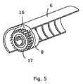
図5は、注入装置のハウジング6の半分の切開図を示す。図に示すように、駆動部材8は歯車型の係合領域/部分17を含む。同様に、ハウジング6は対応する係合領域/部分16を含み、この係合領域/部分16は歯車の歯17を受け、歯17に係合する。 FIG. 5 shows a cut-away view of half of the
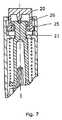
図6は、本発明の別の実施形態を示す。図3〜5に示す実施形態とは異なり、図6に示す実施形態は、回転する外側部分又は要素を含まない。全ての回転部分又は要素はハウジング19の内側に位置している。図6は、バネ要素22によって注入装置の端部に機械的に押し付けられている解放部材20(プッシュボタンの形態)を示している。解放部材20と用量設定部材21とは、用量設定部材21が用量設定位置に位置している限り、係合状態に置かれている。用量設定部材21は、駆動部材(図3に示す駆動部材8)に作用し、更に用量設定部材21に作用するバネ要素(図3に示すバネ要素11)により、同じ注入装置の解放部材20と同じ端部に向かって機械的に押し付けられている。図6に示すように、用量設定部材21は機械的停止部24に対して押し付けられており、この停止部とは、用量設定部材21に形成された肩部がハウジング19の一部に当たって停止する構造である。
図7には中間段階を示す。ここで解放部材20を押して軸方向に沿って十分な距離を移動させると、解放部材20は用量設定部材21から解放される。係合領域25及び26は分離しているが、用量設定部材の肩部が依然としてハウジングの部分に当たるため、用量設定部材21がこの段階で軸方向に移動してはいない。このように、駆動部材(図示しない)が依然としてハウジングと係合しているため、用量設定部材21の回転は阻止されている。FIG. 6 shows another embodiment of the present invention. Unlike the embodiment shown in FIGS. 3-5, the embodiment shown in FIG. 6 does not include a rotating outer portion or element. All rotating parts or elements are located inside the
FIG. 7 shows an intermediate stage. When the
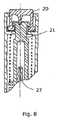
図8では、用量設定部材21がアンプル(図示しない)に向かって軸方向に沿って一定の距離だけ移動しており、よって用量設定部材が自由に回転可能であることにより、ピストンロッド27が設定された用量の薬剤をアンプル(図示しない)から押し出す。解放部材20と用量設定部材21は、図8では分離している。これは、設定用量が注入される間は解放部材20がハウジングに対して回転しないことを意味する。次いで、設定用量が注入された後、ユーザが親指又は人差し指を解放部材から外すと、解放部材と用量設定部材は図6に示すそれぞれの位置へと戻るが、このときバネ要素23は弛緩した状態にある。
新規に用量設定を行う場合、ユーザは、用量設定部材と係合する解放部材を回転させることにより、新規用量を設定することができる。設定用量の注入は、図7及び8に示すステップに従うことにより実行される。In FIG. 8, the
When performing a new dose setting, the user can set a new dose by rotating a release member that engages the dose setting member. The set dose infusion is performed by following the steps shown in FIGS.
図9〜13はエネルギーが蓄積されたパワーリザーバを解放するための解放機構の様々な実施形態を示す。
図9では、注入される用量を設定するとき、注入装置のハウジング30に作用可能に接続するラチェット28を回転させることにより、ねじりバネ(図示しない)にエネルギーが蓄積される。用量設定位置において、ラチェット28は、ラチェットアーム32を介してハウジングの部分31と作用可能に接続している。ねじりバネに蓄積されたエネルギーは、ラチェット28を軸方向に移動させて、ラチェットをハウジングの部分31との接続から解放することにより解放され、このとき、ラチェットアーム32はハウジングの部分33内へと移動し、ピストンロッド34が回転可能となることにより設定用量の薬剤が放出される。
図9に示す実施形態では、用量設定の間、用量指示バレル(図示しない)がプッシュボタン(図示しない)から離れる方向へと移動する。明らかに、用量設定の間、用量指示バレルは反対の方向、つまりプッシュボタンの方向へ移動することができる。9-13 illustrate various embodiments of a release mechanism for releasing a power reservoir with stored energy.
In FIG. 9, when setting the dose to be injected, energy is stored in a torsion spring (not shown) by rotating a
In the embodiment shown in FIG. 9, during dose setting, a dose indicating barrel (not shown) moves away from a push button (not shown). Obviously, during dose setting, the dose indicating barrel can move in the opposite direction, ie in the direction of the push button.
図10に示す実施形態では、ラチェット35はハウジング39と間接的にのみ協働する。図10に示す実施形態の駆動部材は、3つの部分、即ち、ハウジング39と協働する部分36、ピストンロッド40を駆動する部分38、及び部分36と38とを接続する可撓性部材37から構成される。可撓性部材37は軸方向に可撓性を有するが、部分36と38が互いに対して回転するとき、これらの部分の間に実質的に堅固な接続を確立する。このように、可撓性部材37により、部分36と38は確実に互いに対して回転できないように配置される。よって、ラチェット35が注入装置の針側の端部に向かって移動すると、部分36はハウジング39から分離され、よって部分36、37及び38が回転可能となり、これによりピストンロッド40が回転する。回転するピストンロッド40により、設定された用量の薬剤が注入装置から放出される。
図11に示す実施形態は図9に示すものと同様であるが、(駆動部材でなく)ハウジングにガイドトラックが設けられていることにより、及び(ピストンロッドとハウジングの代わりに)ピストンロッドと駆動部材とがネジ係合することにより、ピストンロッドが前進する点で図9とは異なる。
図12及び13は、ラチェット、駆動部材及びハウジングの間の他の解放機構を示す。In the embodiment shown in FIG. 10, the
The embodiment shown in FIG. 11 is similar to that shown in FIG. 9 except that the guide track is provided in the housing (not the drive member) and the piston rod and drive (instead of the piston rod and housing). 9 is different from FIG. 9 in that the piston rod advances by screw engagement with the member.
Figures 12 and 13 show another release mechanism between the ratchet, the drive member and the housing.
Claims (15)
Translated fromJapaneseApplications Claiming Priority (3)
| Application Number | Priority Date | Filing Date | Title |
|---|---|---|---|
| DKPA200500113 | 2005-01-21 | ||
| DKPA200500113 | 2005-01-21 | ||
| PCT/DK2006/000032WO2006076921A1 (en) | 2005-01-21 | 2006-01-20 | An automatic injection device with a top release mechanism |
Publications (2)
| Publication Number | Publication Date |
|---|---|
| JP2008528071Atrue JP2008528071A (en) | 2008-07-31 |
| JP4970282B2 JP4970282B2 (en) | 2012-07-04 |
Family
ID=36218443
Family Applications (1)
| Application Number | Title | Priority Date | Filing Date |
|---|---|---|---|
| JP2007551546AActiveJP4970282B2 (en) | 2005-01-21 | 2006-01-20 | Automatic injection device with release mechanism on top |
Country Status (12)
| Country | Link |
|---|---|
| US (7) | US8096978B2 (en) |
| EP (1) | EP1843809B1 (en) |
| JP (1) | JP4970282B2 (en) |
| CN (1) | CN100571805C (en) |
| AU (1) | AU2006207744B2 (en) |
| BR (1) | BRPI0606607B8 (en) |
| CA (1) | CA2594764C (en) |
| DK (1) | DK1843809T3 (en) |
| ES (1) | ES2633917T3 (en) |
| PL (1) | PL1843809T3 (en) |
| RU (1) | RU2401133C2 (en) |
| WO (1) | WO2006076921A1 (en) |
Cited By (13)
| Publication number | Priority date | Publication date | Assignee | Title |
|---|---|---|---|---|
| JP2012506273A (en)* | 2008-10-24 | 2012-03-15 | ノボ・ノルデイスク・エー/エス | Dial-down mechanism for roll-up pen |
| JP2014530691A (en)* | 2011-10-21 | 2014-11-20 | サノフイ | Automatic syringe |
| US9022991B2 (en) | 2000-06-16 | 2015-05-05 | Novo Nordisk A/S | Injection device |
| JP2015525664A (en)* | 2012-08-20 | 2015-09-07 | ノボ・ノルデイスク・エー/エス | Spring loaded injection device with injection button |
| US9192727B2 (en) | 2006-05-18 | 2015-11-24 | Novo Nordisk A/S | Injection device with mode locking means |
| JP2016514605A (en)* | 2013-04-10 | 2016-05-23 | サノフイ | Drive mechanism of drug delivery device |
| JP2016526991A (en)* | 2013-07-17 | 2016-09-08 | サノフイ | Drug delivery device counting mechanism |
| US9533106B2 (en) | 2011-12-29 | 2017-01-03 | Novo Nordisk A/S | Torsion-spring based wind-up auto injector pen with dial-up/dial-down mechanism |
| USRE46363E1 (en) | 2004-10-21 | 2017-04-11 | Novo Nordisk A/S | Dial-down mechanism for wind-up pen |
| JP2017520370A (en)* | 2014-07-01 | 2017-07-27 | サノフイ | Spring arrangement and drug delivery device having spring arrangement |
| JP2017520373A (en)* | 2014-07-01 | 2017-07-27 | サノフイ | Drug delivery device |
| JP2017520371A (en)* | 2014-07-01 | 2017-07-27 | サノフイ | Drug delivery device |
| JP2021504039A (en)* | 2017-11-27 | 2021-02-15 | サノフイSanofi | Ratchet system for drug delivery devices |
Families Citing this family (118)
| Publication number | Priority date | Publication date | Assignee | Title |
|---|---|---|---|---|
| WO2003068290A2 (en) | 2002-02-11 | 2003-08-21 | Antares Pharma, Inc. | Intradermal injector |
| EP1843809B1 (en) | 2005-01-21 | 2017-04-19 | Novo Nordisk A/S | An automatic injection device with a top release mechanism |
| HUE042286T2 (en) | 2005-01-24 | 2019-06-28 | Antares Pharma Inc | Needle-filled pre-filled syringe |
| US20090043264A1 (en) | 2005-04-24 | 2009-02-12 | Novo Nordisk A/S | Injection Device |
| PL1909871T5 (en) | 2005-07-27 | 2014-05-30 | Novo Nordisk As | Injection device with dose limiting mechanism and additional safety mechanism |
| US8920383B2 (en) | 2005-07-27 | 2014-12-30 | Novo Nordisk A/S | Dose mechanism for an injection device for limiting a dose setting corresponding to the amount of medicament left |
| GB0524604D0 (en) | 2005-12-02 | 2006-01-11 | Owen Mumford Ltd | Injection method and apparatus |
| DE102005060928A1 (en)* | 2005-12-20 | 2007-06-28 | Tecpharma Licensing Ag | Injection device with axially overlapping metering or display element |
| GB2434103B (en) | 2006-01-12 | 2009-11-25 | Owen Mumford Ltd | Lancet firing device |
| JP5062768B2 (en) | 2006-03-10 | 2012-10-31 | ノボ・ノルデイスク・エー/エス | INJECTION DEVICE AND METHOD FOR REPLACING CARTRIDGE OF THE DEVICE |
| CN101400394B (en) | 2006-03-10 | 2012-07-04 | 诺沃-诺迪斯克有限公司 | An injection device having a gearing arrangement |
| WO2007131013A1 (en) | 2006-05-03 | 2007-11-15 | Antares Pharma, Inc. | Two-stage reconstituting injector |
| WO2007131025A1 (en) | 2006-05-03 | 2007-11-15 | Antares Pharma, Inc. | Injector with adjustable dosing |
| ATE458517T1 (en) | 2006-05-16 | 2010-03-15 | Novo Nordisk As | TRANSMISSION MECHANISM FOR AN INJECTION DEVICE |
| US8052655B2 (en)* | 2006-09-29 | 2011-11-08 | Novo Nordisk A/S | Injection device with electronic detecting means |
| BRPI0809265A2 (en) | 2007-03-23 | 2014-10-07 | Novo Nordisk As | INJECTION DEVICE INCLUDING A TIGHTENING NUT |
| US9108006B2 (en) | 2007-08-17 | 2015-08-18 | Novo Nordisk A/S | Medical device with value sensor |
| CA2707820A1 (en) | 2007-12-31 | 2009-07-09 | Novo Nordisk A/S | Electronically monitored injection device |
| EP3636301A1 (en) | 2008-03-10 | 2020-04-15 | Antares Pharma, Inc. | Injector safety device |
| US8376993B2 (en) | 2008-08-05 | 2013-02-19 | Antares Pharma, Inc. | Multiple dosage injector |
| ES2766253T3 (en) | 2008-09-18 | 2020-06-12 | Becton Dickinson Co | Medical Plunger Injector with Ratchet Function |
| EP2328638B1 (en)* | 2008-09-18 | 2020-06-03 | Becton, Dickinson and Company | Medical injector with button activation |
| GB2465390A (en) | 2008-11-17 | 2010-05-19 | Owen Mumford Ltd | Syringe needle cover remover |
| US9526840B2 (en) | 2009-03-31 | 2016-12-27 | Sanofi-Aventis Deutschland Gmbh | Drug delivery device |
| PL214940B1 (en)* | 2009-07-31 | 2013-09-30 | Lozano Platonoff Alberto | Indication mechanism of an automatic applicator, especially for insulin |
| CA2771273A1 (en) | 2009-08-27 | 2011-03-03 | Sanofi-Aventis Deutschland Gmbh | Housing component for a drug delivery device |
| DK2536452T3 (en) | 2010-02-18 | 2019-01-02 | Sanofi Aventis Deutschland | autoinjector |
| WO2011133089A1 (en)* | 2010-04-19 | 2011-10-27 | Shl Group Ab | A self-administration medicament delivery device |
| EP2399635A1 (en) | 2010-06-28 | 2011-12-28 | Sanofi-Aventis Deutschland GmbH | Auto-injector |
| GB201018827D0 (en) | 2010-11-08 | 2010-12-22 | Owen Mumford Ltd | Injection device |
| EP2468333A1 (en) | 2010-12-21 | 2012-06-27 | Sanofi-Aventis Deutschland GmbH | Auto-injector |
| USRE48593E1 (en) | 2010-12-21 | 2021-06-15 | Sanofi-Aventis Deutschland Gmbh | Auto-injector |
| EP2468330A1 (en) | 2010-12-21 | 2012-06-27 | Sanofi-Aventis Deutschland GmbH | Auto-injector |
| EP2489385A1 (en) | 2011-02-18 | 2012-08-22 | Sanofi-Aventis Deutschland GmbH | Auto-injector |
| CN105641782B (en)* | 2011-03-17 | 2019-06-14 | 贝克顿·迪金森公司 | Medical injector with ratchet-type plunger |
| US20140194826A1 (en) | 2011-07-07 | 2014-07-10 | Novo Nordisk A/S | Drug delivery injection pen with add-on dose capturing and display module |
| JP6106666B2 (en) | 2011-07-07 | 2017-04-05 | ノボ・ノルデイスク・エー/エス | Drug delivery injection pen with add-on medication acquisition / display module |
| US9220660B2 (en) | 2011-07-15 | 2015-12-29 | Antares Pharma, Inc. | Liquid-transfer adapter beveled spike |
| US8496619B2 (en) | 2011-07-15 | 2013-07-30 | Antares Pharma, Inc. | Injection device with cammed ram assembly |
| JP2014524297A (en) | 2011-08-18 | 2014-09-22 | ノボ・ノルデイスク・エー/エス | Drug delivery device having means for handling data |
| RU2620351C2 (en) | 2011-09-22 | 2017-05-24 | Эббви Инк. | Automated injector |
| CA2849806A1 (en)* | 2011-09-22 | 2013-03-28 | Abbvie Inc. | Automatic injection device |
| WO2013078078A1 (en)* | 2011-11-22 | 2013-05-30 | West Pharmaceutical Services, Inc. | Linear drive and clutch assembly |
| CN103974732B (en)* | 2011-12-14 | 2016-08-24 | 诺沃—诺迪斯克有限公司 | Injection pen with mechanical dose display including large number code |
| EP2606924A1 (en) | 2011-12-21 | 2013-06-26 | Sanofi-Aventis Deutschland GmbH | Autoinjector having a retracting syringe carrier |
| WO2013110538A1 (en) | 2012-01-27 | 2013-08-01 | Novo Nordisk A/S | Injection device with a sliding scale |
| US9486583B2 (en) | 2012-03-06 | 2016-11-08 | Antares Pharma, Inc. | Prefilled syringe with breakaway force feature |
| EP2644218B2 (en)* | 2012-03-30 | 2022-11-02 | Tecpharma Licensing AG | Injection device with dose display and clockwork drive |
| EP4186545A1 (en) | 2012-04-06 | 2023-05-31 | Antares Pharma, Inc. | Needle assisted jet injection administration of testosterone compositions |
| WO2013153121A2 (en) | 2012-04-10 | 2013-10-17 | Novo Nordisk A/S | Medical injection device with time delay indicator |
| US9364610B2 (en) | 2012-05-07 | 2016-06-14 | Antares Pharma, Inc. | Injection device with cammed ram assembly |
| CN104379086B (en) | 2012-06-22 | 2016-08-31 | 皇家飞利浦有限公司 | For distributing the Spring driving pump of the discontinuous eruption of liquid |
| WO2014060369A1 (en) | 2012-10-15 | 2014-04-24 | Novo Nordisk A/S | Spring driven injection device |
| PL2950853T3 (en) | 2013-02-01 | 2017-09-29 | Novo Nordisk A/S | A non-axial working end-of content mechanism and an injection device comprising the same |
| DE202013001350U1 (en)* | 2013-02-08 | 2014-05-09 | Haselmeier Gmbh | injection device |
| FI3659647T3 (en) | 2013-02-11 | 2024-03-28 | Antares Pharma Inc | NEEDLE-ASSISTED SPRAY INJECTOR WITH REDUCED TRIGGER FORCE |
| CA2905031C (en) | 2013-03-11 | 2018-01-23 | Hans PFLAUMER | Dosage injector with pinion system |
| US10143805B2 (en) | 2013-04-10 | 2018-12-04 | Sanofi | Drive mechanism for a drug delivery device |
| MX2015014293A (en) | 2013-04-10 | 2015-12-08 | Sanofi Sa | Injection device. |
| AR095808A1 (en) | 2013-04-10 | 2015-11-11 | Sanofi Sa | INJECTION DEVICE |
| JP6419159B2 (en) | 2013-04-10 | 2018-11-07 | サノフイSanofi | Injection device |
| JP6490057B2 (en) | 2013-05-16 | 2019-03-27 | サノフィ−アベンティス・ドイチュラント・ゲゼルシャフト・ミット・ベシュレンクテル・ハフツング | Drug delivery device assembly and drug delivery device |
| US10137251B2 (en)* | 2013-05-27 | 2018-11-27 | Sanofi-Aventis Deutschland Gmbh | Assembly for a drug delivery device and drug delivery device |
| EP2823841A1 (en) | 2013-07-09 | 2015-01-14 | Sanofi-Aventis Deutschland GmbH | Autoinjector |
| TW201511785A (en) | 2013-07-17 | 2015-04-01 | Sanofi Sa | Display assembly and dispensing device |
| CN105682712B (en)* | 2013-09-03 | 2020-06-26 | 赛诺菲 | Mechanism for a drug delivery device and drug delivery device comprising the mechanism |
| DK3043842T3 (en)* | 2013-09-10 | 2019-02-18 | Sanofi Sa | DRIVE MECHANISM FOR A PHARMACEUTICAL ADMINISTRATION DEVICE |
| CN103637856B (en)* | 2013-11-14 | 2015-09-09 | 燕海峰 | Singlehanded direct press type continuous and quantitative liquid sucking-discharging device |
| JP2017503567A (en) | 2013-12-20 | 2017-02-02 | サノフィ−アベンティス・ドイチュラント・ゲゼルシャフト・ミット・ベシュレンクテル・ハフツング | Assembly for drug delivery device and drug delivery device |
| WO2015091763A1 (en) | 2013-12-20 | 2015-06-25 | Sanofi-Aventis Deutschland Gmbh | Assembly for a drug delivery device and drug delivery device |
| US20160317749A1 (en)* | 2013-12-20 | 2016-11-03 | Sanofi-Aventis Deutschland Gmbh | Assembly for a drug delivery device and drug delivery device |
| EP3089777A1 (en) | 2014-01-03 | 2016-11-09 | Novo Nordisk A/S | Auto-injection device with button activation |
| DE202014001135U1 (en)* | 2014-02-05 | 2015-05-06 | Haselmeier Gmbh | injection device |
| EP2918298B1 (en) | 2014-03-13 | 2021-05-19 | Ypsomed AG | Improved dosing mechanism for an injection device for administering a product |
| EP2923714A1 (en) | 2014-03-28 | 2015-09-30 | Sanofi-Aventis Deutschland GmbH | Autoinjector triggered by skin contact |
| DE102014008610A1 (en)* | 2014-06-06 | 2015-12-17 | Kocher-Plastik Maschinenbau Gmbh | dispenser |
| EP3164177B1 (en)* | 2014-07-01 | 2019-08-21 | Sanofi | Drug delivery device |
| TW201603849A (en)* | 2014-07-01 | 2016-02-01 | 賽諾菲公司 | Clicker arrangement and drug delivery herewith |
| EP3193980B1 (en) | 2014-09-15 | 2021-06-16 | Novo Nordisk A/S | Torsion spring driven injection device |
| TW201622762A (en)* | 2014-10-09 | 2016-07-01 | 賽諾菲公司 | Insert and drug delivery device herewith |
| GB2538566B (en)* | 2015-05-22 | 2020-09-30 | Owen Mumford Ltd | Injection device |
| TW201707738A (en) | 2015-06-03 | 2017-03-01 | 賽諾菲阿凡提斯德意志有限公司 | Syringe holder and autoinjector (2) |
| DE202015006841U1 (en)* | 2015-09-30 | 2016-01-15 | Haselmeier Ag | injection device |
| PL414382A1 (en) | 2015-10-15 | 2017-04-24 | Copernicus Spółka Z Ograniczoną Odpowiedzialnością | Setting mechanism, in particular for dosing |
| AR106692A1 (en)* | 2015-11-16 | 2018-02-07 | Sanofi Sa | DRUG ADMINISTRATION DEVICE |
| USD818587S1 (en) | 2016-03-29 | 2018-05-22 | Abbevie Inc. | Automatic injection device |
| CN105749383B (en) | 2016-04-21 | 2017-03-08 | 北京甘甘科技有限公司 | Pre-filled pen-type injector |
| EP3515408A1 (en) | 2016-09-23 | 2019-07-31 | Delpor, Inc. | Stable compositions for incretin mimetic compounds |
| US10329075B2 (en)* | 2017-05-12 | 2019-06-25 | Jetty Marketing, Llc. | Dispenser for viscous cannabis fluids and means thereof |
| JP7200134B2 (en)* | 2017-06-08 | 2023-01-06 | アムジエン・インコーポレーテツド | Torque driven drug delivery device |
| ES2985951T3 (en) | 2017-08-18 | 2024-11-07 | Lilly Co Eli | Dosing measurement module on injection pen |
| RS65380B1 (en) | 2017-08-24 | 2024-04-30 | Novo Nordisk As | Glp-1 compositions and uses thereof |
| EP3694584A1 (en) | 2017-10-10 | 2020-08-19 | Novo Nordisk A/S | Prefilled drug delivery device with reduced air gap |
| FR3072297B1 (en)* | 2017-10-17 | 2023-05-12 | Edix Sa | MANUAL INJECTION DEVICE |
| USD869647S1 (en)* | 2018-01-22 | 2019-12-10 | Joshua Dorsey | Syringe |
| EP3545988A1 (en)* | 2018-03-29 | 2019-10-02 | Tecpharma Licensing AG | Dosing device with positioning device for an injector |
| WO2019192662A1 (en) | 2018-04-04 | 2019-10-10 | Cpu Innovation Aps | Auto injector with improved functionality |
| US20220118184A1 (en) | 2019-01-04 | 2022-04-21 | Novo Nordisk A/S | A shield trigger mechanism and an injection device with a shield trigger mechanism |
| EP3714704A1 (en)* | 2019-03-14 | 2020-09-30 | Canopy Growth Corporation | Concentrate dispenser |
| BR112022004829A2 (en)* | 2019-09-26 | 2022-06-07 | Battelle Memorial Institute | Plant supplement supply kits, plant supplement supply kit inserts and methods for supplying plant supplements |
| IL294520A (en) | 2020-02-18 | 2022-09-01 | Novo Nordisk As | Pharmaceutical formulations |
| US12338059B2 (en) | 2021-08-13 | 2025-06-24 | Jetty Marketing, LLC | Apparatus, system and method comprising a dispenser with a modular cartridge for the dispensing of cannabis extract |
| IL312672A (en) | 2021-11-10 | 2024-07-01 | I2O Therapeutics Inc | Ionic liquid compositions |
| EP4249016A1 (en) | 2022-03-24 | 2023-09-27 | Sanofi | Actuating unit for a drug delivery device and related items |
| EP4484022A1 (en)* | 2023-06-29 | 2025-01-01 | medmix Switzerland AG | Dispensing devices |
| WO2025146464A1 (en) | 2024-01-05 | 2025-07-10 | Sanofi | Electronic add-on module and assembly of an electronic add-on module and a drug delivery device |
| WO2025146466A1 (en) | 2024-01-05 | 2025-07-10 | Sanofi | Electronic add-on module and assembly of an electronic add-on module and a drug delivery device |
| US12138428B1 (en) | 2024-01-24 | 2024-11-12 | Sanofi | Electronic add-on module and assembly of an electronic add-on module and a drug delivery device |
| EP4591905A1 (en) | 2024-01-24 | 2025-07-30 | Sanofi | Electronic add-on module and assembly of an electronic add-on module and a drug delivery device |
| WO2025157893A1 (en) | 2024-01-24 | 2025-07-31 | Sanofi | Electronic add-on module and assembly of an electronic add-on module and a drug delivery device |
| WO2025181154A1 (en) | 2024-02-28 | 2025-09-04 | Sanofi | Attachment mechanism, module and assembly herewith |
| US12357764B1 (en) | 2024-02-28 | 2025-07-15 | Sanofi | Attachment mechanism, module and assembly herewith |
| EP4609896A1 (en) | 2024-02-28 | 2025-09-03 | Sanofi | Attachment mechanism, module and assembly herewith |
| WO2025181125A1 (en) | 2024-02-28 | 2025-09-04 | Sanofi | Attachment mechanism, module and assembly herewith |
| EP4609897A1 (en) | 2024-02-28 | 2025-09-03 | Sanofi | Attachment mechanism, module and assembly herewith |
| US12144969B1 (en) | 2024-02-28 | 2024-11-19 | Sanofi | Attachment mechanism, module and assembly herewith |
| EP4623956A1 (en) | 2024-03-28 | 2025-10-01 | Sanofi | Attachment mechanism, module and assembly herewith |
| US12239828B1 (en) | 2024-03-28 | 2025-03-04 | Sanofi | Attachment mechanism, module and assembly herewith |
Citations (5)
| Publication number | Priority date | Publication date | Assignee | Title |
|---|---|---|---|---|
| JPH0271758A (en)* | 1988-04-18 | 1990-03-12 | Turner Robert Charles | Syringe |
| JPH05161712A (en)* | 1991-05-30 | 1993-06-29 | Owen Mumford Ltd | Injector |
| JP2002502296A (en)* | 1997-06-04 | 2002-01-22 | イーライ・リリー・アンド・カンパニー | Drug delivery device |
| JP2003516193A (en)* | 1999-12-09 | 2003-05-13 | ノボ ノルディスク アクティーゼルスカブ | Injection device |
| US20040019326A1 (en)* | 2002-06-24 | 2004-01-29 | Scott Gilbert | Reusable, spring driven autoinjector |
Family Cites Families (32)
| Publication number | Priority date | Publication date | Assignee | Title |
|---|---|---|---|---|
| IE52621B1 (en) | 1981-02-12 | 1988-01-06 | Turner Robert Charles | Dose metering plunger devices for use with syringes |
| DE3715258C2 (en) | 1987-05-08 | 1996-10-31 | Haselmeier Wilhelm Fa | Injection device |
| NL8701091A (en) | 1987-05-08 | 1988-12-01 | Spruyt Hillen Bv | INJECTION PEN. |
| US5226895A (en)* | 1989-06-05 | 1993-07-13 | Eli Lilly And Company | Multiple dose injection pen |
| DK175491D0 (en)* | 1991-10-18 | 1991-10-18 | Novo Nordisk As | APPARATUS |
| US5279585A (en)* | 1992-02-04 | 1994-01-18 | Becton, Dickinson And Company | Medication delivery pen having improved dose delivery features |
| US5320609A (en) | 1992-12-07 | 1994-06-14 | Habley Medical Technology Corporation | Automatic pharmaceutical dispensing syringe |
| US5383865A (en)* | 1993-03-15 | 1995-01-24 | Eli Lilly And Company | Medication dispensing device |
| CH688225A5 (en)* | 1993-06-04 | 1997-06-30 | Medimpex Ets | Feeding device for an injection device. |
| US5540664A (en)* | 1993-05-27 | 1996-07-30 | Washington Biotech Corporation | Reloadable automatic or manual emergency injection system |
| US5536249A (en)* | 1994-03-09 | 1996-07-16 | Visionary Medical Products, Inc. | Pen-type injector with a microprocessor and blood characteristic monitor |
| JP3568959B2 (en)* | 1995-03-07 | 2004-09-22 | イーライ・リリー・アンド・カンパニー | Reusable dosing device |
| AU1860697A (en)* | 1995-09-08 | 1997-07-28 | Visionary Medical Products Corporation | Pen-type injector drive mechanism |
| US5658259A (en)* | 1995-10-19 | 1997-08-19 | Meridian Medical Technologies, Inc. | Dental cartridge assembly auto-injector with protective needle cover |
| DK0831947T3 (en)* | 1996-04-02 | 2002-12-23 | Disetronic Licensing Ag | injector |
| DE19723647C1 (en)* | 1997-06-05 | 1998-12-24 | Disetronic Licensing Ag | Fluid dosing unit indicator for e.g. insulin or for pipetting laboratory fluids |
| CZ297361B6 (en)* | 1998-01-30 | 2006-11-15 | Novo Nordisk A/S | Injection syringe |
| DE19822031C2 (en)* | 1998-05-15 | 2000-03-23 | Disetronic Licensing Ag | Auto injection device |
| DE19900792C1 (en)* | 1999-01-12 | 2000-06-15 | Disetronic Licensing Ag | Injection unit forming part of e.g. pen-type self-injection syringe has continuous dosing stop in spiral form with constant pitch ensuring close fine control and accuracy in use |
| ES2197108T3 (en)* | 1999-07-27 | 2004-01-01 | Pharma Consult Ges.M.B.H. | DEVICES FOR AUTOMATICALLY INJECTING INJECTION LIQUIDS. |
| US6663602B2 (en) | 2000-06-16 | 2003-12-16 | Novo Nordisk A/S | Injection device |
| AU2001281753A1 (en) | 2000-08-29 | 2002-03-13 | Novo-Nordisk A/S | Automatic injection device with torsion function for retraction of needle |
| US6387078B1 (en)* | 2000-12-21 | 2002-05-14 | Gillespie, Iii Richard D. | Automatic mixing and injecting apparatus |
| US6899699B2 (en) | 2001-01-05 | 2005-05-31 | Novo Nordisk A/S | Automatic injection device with reset feature |
| US6673049B2 (en)* | 2001-02-15 | 2004-01-06 | Disetronic Licensing Ag | Injection device for injecting fluid |
| GB0211294D0 (en) | 2002-05-17 | 2002-06-26 | Owen Mumford Ltd | Improvements relating to injection devices |
| DE10229138B4 (en)* | 2002-06-28 | 2008-01-31 | Tecpharma Licensing Ag | Product diverter with piston rod emergency reset |
| DE20317377U1 (en) | 2003-11-03 | 2005-03-17 | B D Medico S A R L | injection device |
| US7740618B2 (en) | 2004-10-14 | 2010-06-22 | Novo Nordisk A/S | Syringe device |
| KR101278123B1 (en) | 2004-10-21 | 2013-06-24 | 노보 노르디스크 에이/에스 | Injection device with torsion spring and rotatable display |
| EP1843809B1 (en)* | 2005-01-21 | 2017-04-19 | Novo Nordisk A/S | An automatic injection device with a top release mechanism |
| US20120173441A1 (en) | 2011-01-05 | 2012-07-05 | Google Inc. | Ownership Resolution System |
- 2006
- 2006-01-20EPEP06701034.8Apatent/EP1843809B1/enactiveActive
- 2006-01-20USUS11/813,435patent/US8096978B2/enactiveActive
- 2006-01-20BRBRPI0606607Apatent/BRPI0606607B8/enactiveIP Right Grant
- 2006-01-20AUAU2006207744Apatent/AU2006207744B2/enactiveActive
- 2006-01-20CNCNB2006800027648Apatent/CN100571805C/enactiveActive
- 2006-01-20CACA 2594764patent/CA2594764C/ennot_activeExpired - Fee Related
- 2006-01-20WOPCT/DK2006/000032patent/WO2006076921A1/enactiveApplication Filing
- 2006-01-20JPJP2007551546Apatent/JP4970282B2/enactiveActive
- 2006-01-20DKDK06701034.8Tpatent/DK1843809T3/enactive
- 2006-01-20RURU2007127537Apatent/RU2401133C2/enactive
- 2006-01-20PLPL06701034Tpatent/PL1843809T3/enunknown
- 2006-01-20ESES06701034.8Tpatent/ES2633917T3/enactiveActive
- 2011
- 2011-12-15USUS13/326,738patent/US9108002B2/enactiveActive
- 2015
- 2015-07-13USUS14/797,350patent/US9616180B2/enactiveActive
- 2017
- 2017-02-24USUS15/441,638patent/US10376652B2/enactiveActive
- 2019
- 2019-06-25USUS16/452,049patent/US11311679B2/enactiveActive
- 2022
- 2022-03-18USUS17/698,568patent/US12070586B2/enactiveActive
- 2024
- 2024-07-19USUS18/778,792patent/US20240366880A1/enactivePending
Patent Citations (5)
| Publication number | Priority date | Publication date | Assignee | Title |
|---|---|---|---|---|
| JPH0271758A (en)* | 1988-04-18 | 1990-03-12 | Turner Robert Charles | Syringe |
| JPH05161712A (en)* | 1991-05-30 | 1993-06-29 | Owen Mumford Ltd | Injector |
| JP2002502296A (en)* | 1997-06-04 | 2002-01-22 | イーライ・リリー・アンド・カンパニー | Drug delivery device |
| JP2003516193A (en)* | 1999-12-09 | 2003-05-13 | ノボ ノルディスク アクティーゼルスカブ | Injection device |
| US20040019326A1 (en)* | 2002-06-24 | 2004-01-29 | Scott Gilbert | Reusable, spring driven autoinjector |
Cited By (17)
| Publication number | Priority date | Publication date | Assignee | Title |
|---|---|---|---|---|
| US9022991B2 (en) | 2000-06-16 | 2015-05-05 | Novo Nordisk A/S | Injection device |
| US10245383B2 (en) | 2000-06-16 | 2019-04-02 | Novo Nordisk A/S | Injection device |
| USRE46363E1 (en) | 2004-10-21 | 2017-04-11 | Novo Nordisk A/S | Dial-down mechanism for wind-up pen |
| US9192727B2 (en) | 2006-05-18 | 2015-11-24 | Novo Nordisk A/S | Injection device with mode locking means |
| JP2012506273A (en)* | 2008-10-24 | 2012-03-15 | ノボ・ノルデイスク・エー/エス | Dial-down mechanism for roll-up pen |
| US9132239B2 (en) | 2008-10-24 | 2015-09-15 | Novo Nordisk A/S | Dial-down mechanism for wind-up pen |
| JP2014530691A (en)* | 2011-10-21 | 2014-11-20 | サノフイ | Automatic syringe |
| US9533106B2 (en) | 2011-12-29 | 2017-01-03 | Novo Nordisk A/S | Torsion-spring based wind-up auto injector pen with dial-up/dial-down mechanism |
| JP2015525664A (en)* | 2012-08-20 | 2015-09-07 | ノボ・ノルデイスク・エー/エス | Spring loaded injection device with injection button |
| JP2016514605A (en)* | 2013-04-10 | 2016-05-23 | サノフイ | Drive mechanism of drug delivery device |
| JP2016526991A (en)* | 2013-07-17 | 2016-09-08 | サノフイ | Drug delivery device counting mechanism |
| JP2017520370A (en)* | 2014-07-01 | 2017-07-27 | サノフイ | Spring arrangement and drug delivery device having spring arrangement |
| JP2017520373A (en)* | 2014-07-01 | 2017-07-27 | サノフイ | Drug delivery device |
| JP2017520371A (en)* | 2014-07-01 | 2017-07-27 | サノフイ | Drug delivery device |
| US11185633B2 (en) | 2014-07-01 | 2021-11-30 | Sanofi | Spring arrangement and drug delivery device herewith |
| JP2021504039A (en)* | 2017-11-27 | 2021-02-15 | サノフイSanofi | Ratchet system for drug delivery devices |
| JP7398372B2 (en) | 2017-11-27 | 2023-12-14 | サノフイ | Ratchet system for drug delivery devices |
Also Published As
| Publication number | Publication date |
|---|---|
| US20240366880A1 (en) | 2024-11-07 |
| US12070586B2 (en) | 2024-08-27 |
| US20150314076A1 (en) | 2015-11-05 |
| US20080306446A1 (en) | 2008-12-11 |
| US20220249780A1 (en) | 2022-08-11 |
| RU2401133C2 (en) | 2010-10-10 |
| BRPI0606607B1 (en) | 2021-02-02 |
| US20190314579A1 (en) | 2019-10-17 |
| US9108002B2 (en) | 2015-08-18 |
| BRPI0606607B8 (en) | 2021-06-22 |
| EP1843809B1 (en) | 2017-04-19 |
| ES2633917T3 (en) | 2017-09-26 |
| CN100571805C (en) | 2009-12-23 |
| CA2594764C (en) | 2014-01-14 |
| US10376652B2 (en) | 2019-08-13 |
| AU2006207744A1 (en) | 2006-07-27 |
| BRPI0606607A2 (en) | 2010-03-16 |
| US9616180B2 (en) | 2017-04-11 |
| EP1843809A1 (en) | 2007-10-17 |
| US20120083746A1 (en) | 2012-04-05 |
| JP4970282B2 (en) | 2012-07-04 |
| US11311679B2 (en) | 2022-04-26 |
| CN101107031A (en) | 2008-01-16 |
| WO2006076921A1 (en) | 2006-07-27 |
| PL1843809T3 (en) | 2017-09-29 |
| RU2007127537A (en) | 2009-02-27 |
| AU2006207744B2 (en) | 2011-08-11 |
| CA2594764A1 (en) | 2006-07-27 |
| US8096978B2 (en) | 2012-01-17 |
| DK1843809T3 (en) | 2017-07-31 |
| US20170165431A1 (en) | 2017-06-15 |
Similar Documents
| Publication | Publication Date | Title |
|---|---|---|
| JP4970282B2 (en) | Automatic injection device with release mechanism on top | |
| US8376997B2 (en) | Device for delivering medicament | |
| EP2414011B1 (en) | Medicament delivery device | |
| US8083711B2 (en) | Injection device with internal dose indicator | |
| EP2968789B1 (en) | Dispensing mechanism for a medical device | |
| JP2010521275A (en) | Injection device with lock nut | |
| WO2015090320A2 (en) | Dose delivery device with improved handling | |
| EP2968790B1 (en) | Dispensing mechanism for a medical device | |
| GB2511807A (en) | Dispensing mechanism for a medical device | |
| GB2511804A (en) | Dispensing mechanism for a medical device | |
| GB2511805A (en) | Dispensing mechanism for a medical device |
Legal Events
| Date | Code | Title | Description |
|---|---|---|---|
| A621 | Written request for application examination | Free format text:JAPANESE INTERMEDIATE CODE: A621 Effective date:20090106 | |
| A977 | Report on retrieval | Free format text:JAPANESE INTERMEDIATE CODE: A971007 Effective date:20110421 | |
| A131 | Notification of reasons for refusal | Free format text:JAPANESE INTERMEDIATE CODE: A131 Effective date:20110524 | |
| A521 | Request for written amendment filed | Free format text:JAPANESE INTERMEDIATE CODE: A523 Effective date:20110818 | |
| TRDD | Decision of grant or rejection written | ||
| A01 | Written decision to grant a patent or to grant a registration (utility model) | Free format text:JAPANESE INTERMEDIATE CODE: A01 Effective date:20120306 | |
| A01 | Written decision to grant a patent or to grant a registration (utility model) | Free format text:JAPANESE INTERMEDIATE CODE: A01 | |
| A61 | First payment of annual fees (during grant procedure) | Free format text:JAPANESE INTERMEDIATE CODE: A61 Effective date:20120404 | |
| FPAY | Renewal fee payment (event date is renewal date of database) | Free format text:PAYMENT UNTIL: 20150413 Year of fee payment:3 | |
| R150 | Certificate of patent or registration of utility model | Ref document number:4970282 Country of ref document:JP Free format text:JAPANESE INTERMEDIATE CODE: R150 Free format text:JAPANESE INTERMEDIATE CODE: R150 | |
| R250 | Receipt of annual fees | Free format text:JAPANESE INTERMEDIATE CODE: R250 | |
| R250 | Receipt of annual fees | Free format text:JAPANESE INTERMEDIATE CODE: R250 | |
| R250 | Receipt of annual fees | Free format text:JAPANESE INTERMEDIATE CODE: R250 | |
| R250 | Receipt of annual fees | Free format text:JAPANESE INTERMEDIATE CODE: R250 | |
| R250 | Receipt of annual fees | Free format text:JAPANESE INTERMEDIATE CODE: R250 | |
| R250 | Receipt of annual fees | Free format text:JAPANESE INTERMEDIATE CODE: R250 | |
| R250 | Receipt of annual fees | Free format text:JAPANESE INTERMEDIATE CODE: R250 | |
| R250 | Receipt of annual fees | Free format text:JAPANESE INTERMEDIATE CODE: R250 | |
| R250 | Receipt of annual fees | Free format text:JAPANESE INTERMEDIATE CODE: R250 | |
| R250 | Receipt of annual fees | Free format text:JAPANESE INTERMEDIATE CODE: R250 | |
| R250 | Receipt of annual fees | Free format text:JAPANESE INTERMEDIATE CODE: R250 |