JP2008526372A - 3D implantable bone support - Google Patents
3D implantable bone supportDownload PDFInfo
- Publication number
- JP2008526372A JP2008526372AJP2007550516AJP2007550516AJP2008526372AJP 2008526372 AJP2008526372 AJP 2008526372AJP 2007550516 AJP2007550516 AJP 2007550516AJP 2007550516 AJP2007550516 AJP 2007550516AJP 2008526372 AJP2008526372 AJP 2008526372A
- Authority
- JP
- Japan
- Prior art keywords
- semi
- bone
- extensible structure
- catheter
- extensible
- Prior art date
- Legal status (The legal status is an assumption and is not a legal conclusion. Google has not performed a legal analysis and makes no representation as to the accuracy of the status listed.)
- Granted
Links
- 210000000988bone and boneAnatomy0.000titleclaimsabstractdescription112
- 239000000463materialSubstances0.000claimsabstractdescription89
- 238000000034methodMethods0.000claimsabstractdescription62
- 238000011282treatmentMethods0.000claimsabstractdescription32
- 201000010099diseaseDiseases0.000claimsdescription18
- 208000037265diseases, disorders, signs and symptomsDiseases0.000claimsdescription18
- 229910001000nickel titaniumInorganic materials0.000claimsdescription12
- HLXZNVUGXRDIFK-UHFFFAOYSA-Nnickel titaniumChemical compound[Ti].[Ti].[Ti].[Ti].[Ti].[Ti].[Ti].[Ti].[Ti].[Ti].[Ti].[Ni].[Ni].[Ni].[Ni].[Ni].[Ni].[Ni].[Ni].[Ni].[Ni].[Ni].[Ni].[Ni].[Ni]HLXZNVUGXRDIFK-UHFFFAOYSA-N0.000claimsdescription12
- 208000014674injuryDiseases0.000claimsdescription11
- 229920003229poly(methyl methacrylate)Polymers0.000claimsdescription10
- 239000004926polymethyl methacrylateSubstances0.000claimsdescription10
- 239000004568cementSubstances0.000claimsdescription9
- 239000007788liquidSubstances0.000claimsdescription9
- 230000006378damageEffects0.000claimsdescription8
- 239000003814drugSubstances0.000claimsdescription8
- 239000000203mixtureSubstances0.000claimsdescription7
- 206010028980NeoplasmDiseases0.000claimsdescription6
- 208000001132OsteoporosisDiseases0.000claimsdescription6
- 208000027418Wounds and injuryDiseases0.000claimsdescription6
- 230000000302ischemic effectEffects0.000claimsdescription6
- 230000017074necrotic cell deathEffects0.000claimsdescription6
- 210000000689upper legAnatomy0.000claimsdescription6
- 239000004698PolyethyleneSubstances0.000claimsdescription5
- -1polyethylenePolymers0.000claimsdescription5
- 229920000573polyethylenePolymers0.000claimsdescription5
- 229940079593drugDrugs0.000claimsdescription4
- 230000001009osteoporotic effectEffects0.000claimsdescription4
- 239000004372Polyvinyl alcoholSubstances0.000claimsdescription3
- 230000007547defectEffects0.000claimsdescription3
- 230000002124endocrineEffects0.000claimsdescription3
- 210000002745epiphysisAnatomy0.000claimsdescription3
- 210000002758humerusAnatomy0.000claimsdescription3
- 206010061289metastatic neoplasmDiseases0.000claimsdescription3
- 229920000747poly(lactic acid)Polymers0.000claimsdescription3
- 229920000728polyesterPolymers0.000claimsdescription3
- 229920000139polyethylene terephthalatePolymers0.000claimsdescription3
- 239000005020polyethylene terephthalateSubstances0.000claimsdescription3
- 239000004626polylactic acidSubstances0.000claimsdescription3
- 229920002451polyvinyl alcoholPolymers0.000claimsdescription3
- 239000003356suture materialSubstances0.000claimsdescription3
- 229920000049Carbon (fiber)Polymers0.000claimsdescription2
- 229920002307DextranPolymers0.000claimsdescription2
- 239000004917carbon fiberSubstances0.000claimsdescription2
- 238000004891communicationMethods0.000claimsdescription2
- VNWKTOKETHGBQD-UHFFFAOYSA-NmethaneChemical compoundCVNWKTOKETHGBQD-UHFFFAOYSA-N0.000claimsdescription2
- 238000007789sealingMethods0.000claimsdescription2
- 229920002994synthetic fiberPolymers0.000claimsdescription2
- 210000001519tissueAnatomy0.000abstractdescription11
- 238000007669thermal treatmentMethods0.000abstractdescription4
- 208000010392Bone FracturesDiseases0.000description13
- 206010017076FractureDiseases0.000description13
- 239000000560biocompatible materialSubstances0.000description7
- 230000001054cortical effectEffects0.000description7
- 238000012423maintenanceMethods0.000description7
- PXHVJJICTQNCMI-UHFFFAOYSA-NNickelChemical compound[Ni]PXHVJJICTQNCMI-UHFFFAOYSA-N0.000description6
- 238000002513implantationMethods0.000description6
- 229910052751metalInorganic materials0.000description6
- 239000002184metalSubstances0.000description6
- 230000035876healingEffects0.000description5
- 239000007943implantSubstances0.000description5
- 230000008733traumaEffects0.000description5
- 208000020084Bone diseaseDiseases0.000description4
- 230000008901benefitEffects0.000description4
- 238000009472formulationMethods0.000description4
- 238000002347injectionMethods0.000description4
- 239000007924injectionSubstances0.000description4
- 239000012528membraneSubstances0.000description4
- 229920000642polymerPolymers0.000description4
- RTAQQCXQSZGOHL-UHFFFAOYSA-NTitaniumChemical compound[Ti]RTAQQCXQSZGOHL-UHFFFAOYSA-N0.000description3
- 239000002639bone cementSubstances0.000description3
- 229920001577copolymerPolymers0.000description3
- 230000008569processEffects0.000description3
- 239000000523sampleSubstances0.000description3
- 210000000278spinal cordAnatomy0.000description3
- 239000010936titaniumSubstances0.000description3
- AOJJSUZBOXZQNB-TZSSRYMLSA-NDoxorubicinChemical compoundO([C@H]1C[C@@](O)(CC=2C(O)=C3C(=O)C=4C=CC=C(C=4C(=O)C3=C(O)C=21)OC)C(=O)CO)[C@H]1C[C@H](N)[C@H](O)[C@H](C)O1AOJJSUZBOXZQNB-TZSSRYMLSA-N0.000description2
- 229910001069Ti alloyInorganic materials0.000description2
- 239000013060biological fluidSubstances0.000description2
- 210000004027cellAnatomy0.000description2
- 230000008859changeEffects0.000description2
- 238000013170computed tomography imagingMethods0.000description2
- 230000000694effectsEffects0.000description2
- 238000010348incorporationMethods0.000description2
- 230000008595infiltrationEffects0.000description2
- 238000001764infiltrationMethods0.000description2
- 238000003780insertionMethods0.000description2
- 230000037431insertionEffects0.000description2
- 230000003211malignant effectEffects0.000description2
- 238000012986modificationMethods0.000description2
- 230000004048modificationEffects0.000description2
- 239000000178monomerSubstances0.000description2
- 229910052759nickelInorganic materials0.000description2
- 229920003023plasticPolymers0.000description2
- 239000004033plasticSubstances0.000description2
- 239000010935stainless steelSubstances0.000description2
- 229910001220stainless steelInorganic materials0.000description2
- 229910052719titaniumInorganic materials0.000description2
- 208000008035Back PainDiseases0.000description1
- 206010010214Compression fractureDiseases0.000description1
- CMSMOCZEIVJLDB-UHFFFAOYSA-NCyclophosphamideChemical compoundClCCN(CCCl)P1(=O)NCCCO1CMSMOCZEIVJLDB-UHFFFAOYSA-N0.000description1
- FBOZXECLQNJBKD-ZDUSSCGKSA-NL-methotrexateChemical compoundC=1N=C2N=C(N)N=C(N)C2=NC=1CN(C)C1=CC=C(C(=O)N[C@@H](CCC(O)=O)C(O)=O)C=C1FBOZXECLQNJBKD-ZDUSSCGKSA-N0.000description1
- 241000124008MammaliaSpecies0.000description1
- 208000031264Nerve root compressionDiseases0.000description1
- 229910000990Ni alloyInorganic materials0.000description1
- 229930012538PaclitaxelNatural products0.000description1
- 208000002193PainDiseases0.000description1
- 208000010378Pulmonary EmbolismDiseases0.000description1
- 206010037779RadiculopathyDiseases0.000description1
- 208000007536ThrombosisDiseases0.000description1
- 210000003484anatomyAnatomy0.000description1
- 239000012620biological materialSubstances0.000description1
- 210000004204blood vesselAnatomy0.000description1
- 210000002449bone cellAnatomy0.000description1
- 210000001185bone marrowAnatomy0.000description1
- 229960004562carboplatinDrugs0.000description1
- 190000008236carboplatinChemical compound0.000description1
- 238000006555catalytic reactionMethods0.000description1
- 210000000038chestAnatomy0.000description1
- 229960004316cisplatinDrugs0.000description1
- DQLATGHUWYMOKM-UHFFFAOYSA-LcisplatinChemical compoundN[Pt](N)(Cl)ClDQLATGHUWYMOKM-UHFFFAOYSA-L0.000description1
- 238000002591computed tomographyMethods0.000description1
- 230000007797corrosionEffects0.000description1
- 238000005260corrosionMethods0.000description1
- 238000002316cosmetic surgeryMethods0.000description1
- 229960004397cyclophosphamideDrugs0.000description1
- 238000000354decomposition reactionMethods0.000description1
- 230000001419dependent effectEffects0.000description1
- 229960004679doxorubicinDrugs0.000description1
- 238000005553drillingMethods0.000description1
- 230000010102embolizationEffects0.000description1
- 238000000799fluorescence microscopyMethods0.000description1
- 230000009931harmful effectEffects0.000description1
- 238000003384imaging methodMethods0.000description1
- 210000001930leg boneAnatomy0.000description1
- 230000004807localizationEffects0.000description1
- 210000004705lumbosacral regionAnatomy0.000description1
- 238000002595magnetic resonance imagingMethods0.000description1
- 230000014759maintenance of locationEffects0.000description1
- 239000011159matrix materialSubstances0.000description1
- 229960001924melphalanDrugs0.000description1
- SGDBTWWWUNNDEQ-LBPRGKRZSA-NmelphalanChemical compoundOC(=O)[C@@H](N)CC1=CC=C(N(CCCl)CCCl)C=C1SGDBTWWWUNNDEQ-LBPRGKRZSA-N0.000description1
- 229910001092metal group alloyInorganic materials0.000description1
- 229960000485methotrexateDrugs0.000description1
- 238000002324minimally invasive surgeryMethods0.000description1
- 210000003739neckAnatomy0.000description1
- 210000005036nerveAnatomy0.000description1
- 230000003287optical effectEffects0.000description1
- 230000000399orthopedic effectEffects0.000description1
- 229960001592paclitaxelDrugs0.000description1
- 210000004197pelvisAnatomy0.000description1
- 239000002243precursorSubstances0.000description1
- 230000002265preventionEffects0.000description1
- 238000001959radiotherapyMethods0.000description1
- 238000011084recoveryMethods0.000description1
- 230000008439repair processEffects0.000description1
- 238000011268retreatmentMethods0.000description1
- 210000000614ribAnatomy0.000description1
- 210000003625skullAnatomy0.000description1
- 208000005198spinal stenosisDiseases0.000description1
- 210000001562sternumAnatomy0.000description1
- 239000013589supplementSubstances0.000description1
- 238000004381surface treatmentMethods0.000description1
- 208000024891symptomDiseases0.000description1
- RCINICONZNJXQF-MZXODVADSA-NtaxolChemical compoundO([C@@H]1[C@@]2(C[C@@H](C(C)=C(C2(C)C)[C@H](C([C@]2(C)[C@@H](O)C[C@H]3OC[C@]3([C@H]21)OC(C)=O)=O)OC(=O)C)OC(=O)[C@H](O)[C@@H](NC(=O)C=1C=CC=CC=1)C=1C=CC=CC=1)O)C(=O)C1=CC=CC=C1RCINICONZNJXQF-MZXODVADSA-N0.000description1
- 229940124597therapeutic agentDrugs0.000description1
- 238000003325tomographyMethods0.000description1
- 238000002604ultrasonographyMethods0.000description1
- 238000012800visualizationMethods0.000description1
Images


Classifications
- A—HUMAN NECESSITIES
- A61—MEDICAL OR VETERINARY SCIENCE; HYGIENE
- A61F—FILTERS IMPLANTABLE INTO BLOOD VESSELS; PROSTHESES; DEVICES PROVIDING PATENCY TO, OR PREVENTING COLLAPSING OF, TUBULAR STRUCTURES OF THE BODY, e.g. STENTS; ORTHOPAEDIC, NURSING OR CONTRACEPTIVE DEVICES; FOMENTATION; TREATMENT OR PROTECTION OF EYES OR EARS; BANDAGES, DRESSINGS OR ABSORBENT PADS; FIRST-AID KITS
- A61F2/00—Filters implantable into blood vessels; Prostheses, i.e. artificial substitutes or replacements for parts of the body; Appliances for connecting them with the body; Devices providing patency to, or preventing collapsing of, tubular structures of the body, e.g. stents
- A61F2/02—Prostheses implantable into the body
- A61F2/30—Joints
- A61F2/32—Joints for the hip
- A61F2/34—Acetabular cups
- A—HUMAN NECESSITIES
- A61—MEDICAL OR VETERINARY SCIENCE; HYGIENE
- A61B—DIAGNOSIS; SURGERY; IDENTIFICATION
- A61B17/00—Surgical instruments, devices or methods
- A61B17/56—Surgical instruments or methods for treatment of bones or joints; Devices specially adapted therefor
- A61B17/58—Surgical instruments or methods for treatment of bones or joints; Devices specially adapted therefor for osteosynthesis, e.g. bone plates, screws or setting implements
- A61B17/68—Internal fixation devices, including fasteners and spinal fixators, even if a part thereof projects from the skin
- A61B17/70—Spinal positioners or stabilisers, e.g. stabilisers comprising fluid filler in an implant
- A61B17/7097—Stabilisers comprising fluid filler in an implant, e.g. balloon; devices for inserting or filling such implants
- A—HUMAN NECESSITIES
- A61—MEDICAL OR VETERINARY SCIENCE; HYGIENE
- A61P—SPECIFIC THERAPEUTIC ACTIVITY OF CHEMICAL COMPOUNDS OR MEDICINAL PREPARATIONS
- A61P19/00—Drugs for skeletal disorders
- A—HUMAN NECESSITIES
- A61—MEDICAL OR VETERINARY SCIENCE; HYGIENE
- A61P—SPECIFIC THERAPEUTIC ACTIVITY OF CHEMICAL COMPOUNDS OR MEDICINAL PREPARATIONS
- A61P19/00—Drugs for skeletal disorders
- A61P19/08—Drugs for skeletal disorders for bone diseases, e.g. rachitism, Paget's disease
- A61P19/10—Drugs for skeletal disorders for bone diseases, e.g. rachitism, Paget's disease for osteoporosis
- A—HUMAN NECESSITIES
- A61—MEDICAL OR VETERINARY SCIENCE; HYGIENE
- A61P—SPECIFIC THERAPEUTIC ACTIVITY OF CHEMICAL COMPOUNDS OR MEDICINAL PREPARATIONS
- A61P35/00—Antineoplastic agents
- A—HUMAN NECESSITIES
- A61—MEDICAL OR VETERINARY SCIENCE; HYGIENE
- A61P—SPECIFIC THERAPEUTIC ACTIVITY OF CHEMICAL COMPOUNDS OR MEDICINAL PREPARATIONS
- A61P35/00—Antineoplastic agents
- A61P35/04—Antineoplastic agents specific for metastasis
- A—HUMAN NECESSITIES
- A61—MEDICAL OR VETERINARY SCIENCE; HYGIENE
- A61P—SPECIFIC THERAPEUTIC ACTIVITY OF CHEMICAL COMPOUNDS OR MEDICINAL PREPARATIONS
- A61P5/00—Drugs for disorders of the endocrine system
- A—HUMAN NECESSITIES
- A61—MEDICAL OR VETERINARY SCIENCE; HYGIENE
- A61P—SPECIFIC THERAPEUTIC ACTIVITY OF CHEMICAL COMPOUNDS OR MEDICINAL PREPARATIONS
- A61P9/00—Drugs for disorders of the cardiovascular system
- A61P9/10—Drugs for disorders of the cardiovascular system for treating ischaemic or atherosclerotic diseases, e.g. antianginal drugs, coronary vasodilators, drugs for myocardial infarction, retinopathy, cerebrovascula insufficiency, renal arteriosclerosis
Landscapes
- Health & Medical Sciences (AREA)
- Orthopedic Medicine & Surgery (AREA)
- Life Sciences & Earth Sciences (AREA)
- Veterinary Medicine (AREA)
- Animal Behavior & Ethology (AREA)
- General Health & Medical Sciences (AREA)
- Public Health (AREA)
- Nuclear Medicine, Radiotherapy & Molecular Imaging (AREA)
- Engineering & Computer Science (AREA)
- Medicinal Chemistry (AREA)
- Organic Chemistry (AREA)
- Pharmacology & Pharmacy (AREA)
- General Chemical & Material Sciences (AREA)
- Chemical Kinetics & Catalysis (AREA)
- Chemical & Material Sciences (AREA)
- Bioinformatics & Cheminformatics (AREA)
- Heart & Thoracic Surgery (AREA)
- Physical Education & Sports Medicine (AREA)
- Surgery (AREA)
- Neurology (AREA)
- Biomedical Technology (AREA)
- Vascular Medicine (AREA)
- Molecular Biology (AREA)
- Medical Informatics (AREA)
- Rheumatology (AREA)
- Cardiology (AREA)
- Diabetes (AREA)
- Oncology (AREA)
- Urology & Nephrology (AREA)
- Endocrinology (AREA)
- Oral & Maxillofacial Surgery (AREA)
- Transplantation (AREA)
- Prostheses (AREA)
- Materials For Medical Uses (AREA)
- Medicines That Contain Protein Lipid Enzymes And Other Medicines (AREA)
- Medicines Containing Antibodies Or Antigens For Use As Internal Diagnostic Agents (AREA)
- Surgical Instruments (AREA)
Abstract
Translated fromJapaneseDescription
Translated fromJapanese (関連出願への相互参照)
本出願は、2005年1月7日に出願された米国仮特許出願第60/641,968号の米国特許法第119条(e)の下の利益を主張し、その開示は、本明細書中に参考として援用される。(Cross-reference to related applications)
This application claims the benefit under 35 USC 119 (e) of US Provisional Patent Application No. 60 / 641,968, filed January 7, 2005, the disclosure of which is hereby incorporated by reference Incorporated herein by reference.
(発明の背景)
哺乳動物中の疾患海綿質組織または損傷海綿質組織のために広範な範囲の処置が当該技術分野で現在知られている。海綿質またはスポンジ状骨は、小柱(ハニカム構造)および皮質骨に対して高いレベルの間隙率を有する。これら小柱間のスペースは、スポンジ状骨を養う血管を含む赤色骨髄で充填されている。スポンジ状骨は、骨盤、肋骨、胸骨、脊椎、頭蓋、および腕骨および脚骨の端部の骨中に見出される。(Background of the Invention)
A wide range of treatments are currently known in the art for diseased or damaged cancellous tissue in mammals. Spongy or sponge-like bone has a high level of porosity relative to trabecular (honeycomb structure) and cortical bone. The space between these trabeculae is filled with red bone marrow that contains blood vessels that feed the sponge-like bone. Spongy bone is found in the bones at the ends of the pelvis, ribs, sternum, spine, skull, and humeral and leg bones.
すべての骨は、制限されないで、骨粗鬆症、骨粗鬆症の骨、骨粗鬆症で骨折した骨幹端および骨端骨、骨粗鬆症椎骨本体、腫瘍に起因する椎骨本体の骨折、特に円形細胞腫瘍、長骨の骨端の虚血壊死、特に近位大腿骨、遠位大腿骨および/または近位上腕骨の虚血壊死、内分泌状態、転移性腫瘍から生じる欠陥を含むような、外傷、疾患プロセス、または骨折によって損傷を受ける。椎骨棘を含む骨は、それらの解剖学的構造の複雑さに起因して処置することが特に困難である。椎骨の有効の処置は、脊髄から発する神経への脊髄の近接によってさらに増悪される。 All bones include, but are not limited to, osteoporosis, osteoporotic bone, metaphyseal and epiphyseal bone fractured in osteoporosis, osteoporotic vertebral body, vertebral body fractures caused by tumors, especially round cell tumors, epiphyses of long bones Damage caused by trauma, disease processes, or fractures, including ischemic necrosis, particularly ischemic necrosis of the proximal femur, distal femur and / or proximal humerus, endocrine status, defects arising from metastatic tumors receive. Bones, including vertebral spines, are particularly difficult to treat due to the complexity of their anatomy. Effective treatment of the vertebra is further exacerbated by the proximity of the spinal cord to the nerve originating from the spinal cord.
骨折または疾患の骨、特に、椎骨の処置において通俗性を得た2つの最小侵襲的手順は、椎骨形成術(vertebroplasty)およびKyphoplastyである。特許文献1は、椎骨形成術を実施するための方法および装置を記載する。椎骨形成術は、ポリメチルメタクリレート(「PMMA」)のようなセメント様材料が、高圧下で椎骨腔中に直接注入される手順である。このセメント様材料は硬化され、そして硬くなる際に、影響された椎骨への構造的支持を提供する。 Two minimally invasive procedures that have become popular in the treatment of fractured or diseased bones, particularly vertebrae, are vertebraplasty and Kyphoplasty. U.S. Patent No. 6,057,032 describes a method and apparatus for performing vertebral plastic surgery. Vertebroplasty is a procedure in which a cement-like material such as polymethylmethacrylate ("PMMA") is injected directly into the vertebral space under high pressure. As the cement-like material hardens and hardens, it provides structural support to the affected vertebrae.
Kyphoplastyでは、小切開が背中に作製される。蛍光造影技法を用いて、外科医はカニューレを所望の位置に案内し、このカニューレを通じてドリルを挿入し、そして皮質壁を通って海綿質中に穴をあけ、椎骨本体内でチャネルを規定する。ドリルは取り除かれ、そしてバルーンカテーテルがチャネル中に挿入される。このバルーンカテーテルは次いで膨張され、海綿質を内側皮質壁に対して押し、その中に腔を規定する。圧縮骨折のためのこの手順の特定の利点は、バルーンカテーテルの膨張が椎骨高さの部分を回復することである。バルーンカテーテルの収縮および除去の後、椎骨形成術で用いられるセメント様材料のような材料が上記の腔を充填するために注入される。このセメントは硬化され、そして手術部位は閉じられる。 In Kyphoplasty, a small incision is made in the back. Using fluorescence imaging techniques, the surgeon guides the cannula to the desired location, inserts a drill through the cannula, drills through the cortical wall and into the cancellous, and defines a channel within the vertebral body. The drill is removed and a balloon catheter is inserted into the channel. The balloon catheter is then inflated to push the cancellous against the inner cortical wall and define a cavity therein. A particular advantage of this procedure for compression fractures is that balloon catheter inflation restores vertebral height. After deflation and removal of the balloon catheter, a material, such as a cement-like material used in kyphoplasty, is injected to fill the cavity. The cement is hardened and the surgical site is closed.
経皮的椎骨形成術およびKyphoplastyの改変例が先行技術で知られている。例えば、特許文献2は、骨中、特に、しかし制限されないで椎骨本体中で腔または通路を形成または拡大し、そして改良された様式で骨に治療物質を送達するためにバルーンを用いることを開示する。特許文献3は、骨中の骨折を減少し、そして脊髄を処置するために穂膨張可能なデバイスを用いることを開示する。特許文献4は、ガイドワイヤ上で骨中に挿入される拡大可能な本体を採用することを開示する。特許文献5は、構造を支持するための移植可能な医療用デバイスを用いることを開示する。特許文献6は、高圧アプリケーターからインプラント送達デバイスまでインプラント材料を送達するための導管を用いることを開示する。特許文献7は、硬い組織インプラント材料の経皮的移植を実施するために正確な深さで案内される器具を用いることを開示する。
前述の手順は、骨損傷および骨疾患の処置において顕著な進歩を提示しているが、それらはリスクなしではない。両方の手順に共通のリスクは、処置された骨中の骨折部位からのセメントの脱出である。これらのリスクは、高い注入圧力に起因して、椎骨形成術でより顕著であり、セメントの骨折部位からの脱出は、血栓症、脊髄狭窄、または神経根圧縮、および稀ではあるが肺動脈塞栓症に至り得る。 While the aforementioned procedures represent a significant advance in the treatment of bone damage and disease, they are not without risk. A common risk for both procedures is the escape of cement from the fracture site in the treated bone. These risks are more pronounced in vertebroplasty due to high injection pressures, and the escape of cement from fracture sites is thrombosis, spinal stenosis, or nerve root compression, and rarely pulmonary embolism Can lead to
前述の手順のさらなる制限は、一旦、骨セメントが硬化すると、椎骨本体からのセメントの引き続く除去が、特に脊椎中の椎骨の場合には、禁止的であることである。 A further limitation of the above procedure is that once the bone cement has hardened, subsequent removal of the cement from the vertebral body is prohibited, especially in the case of vertebrae in the spine.
同様に、前述の方法は、修繕であり、そして、まず第一にこれらの方法の適用を必要にした骨折を引き起こしたか、または起用したかも知れない任意の基礎となる疾患の処置のためには何も提供しない。 Similarly, the methods described above are repairs and for the treatment of any underlying disease that may have caused or may have employed a fracture that necessitated the application of these methods in the first place. Provide nothing.
従って、当該技術分野におけるこれらの最近の進歩にかかわらず、骨骨折および疾患状態を処置するための改良されたデバイスおよび方法に対して継続する必要性が残っている。 Thus, despite these recent advances in the art, there remains a continuing need for improved devices and methods for treating bone fractures and disease states.
(発明の簡単な要旨)
本発明は、疾患または損傷骨組織を処置する方法に関し、処置されるべき骨組織中の内部領域を選択する工程、この処置されるべき骨組織の内部領域中にデバイスを挿入する工程、および処置の間にこのデバイスを用いて骨組織を内部で支持する工程を包含する。(Simple Summary of Invention)
The present invention relates to a method of treating diseased or damaged bone tissue, selecting an internal region in the bone tissue to be treated, inserting a device into the internal region of the bone tissue to be treated, and treatment During which the device is used to internally support the bone tissue.
本発明はまた、カテーテルを備える疾患または損傷骨を処置するためのデバイスに関し、ここで、このカテーテルは、それを通る少なくとも1つの内部通路を規定する主本体、拡大可能な半伸展性構造を備え、ここで、この半伸展性構造は、内部スペース、および除去可能なファスナーを規定し、ここで、このファスナーは、上記カテーテルを上記半伸展性構造に離脱可能に連結する。 The present invention also relates to a device for treating diseased or damaged bone comprising a catheter, wherein the catheter comprises a main body defining at least one internal passage therethrough, an expandable semi-extensible structure. Here, the semi-extensible structure defines an internal space and a removable fastener, wherein the fastener removably couples the catheter to the semi-extensible structure.
(詳細な説明)
本発明は、整形外科の外科用デバイスおよび技法の分野に関する。本発明の処置の方法は、除去可能なファスナー、好ましくはスクリューデバイスによって、好ましくは離脱可能な半伸展性構造に連結されるカテーテル67を用いる工程を含む。このファスナーは、カテーテル67を半伸展性構造49に離脱可能に連結し、そして半伸展性デバイス49をカテーテル67に連結し得、そしてこの半伸展性デバイス49をカテーテル67から外し得る。(Detailed explanation)
The present invention relates to the field of orthopedic surgical devices and techniques. The method of treatment of the present invention comprises the step of using a catheter 67 connected to a removable semi-extensible structure, preferably by a removable fastener, preferably a screw device. The fastener can releasably couple the catheter 67 to the semi-extensible structure 49 and can couple the semi-extensible device 49 to the catheter 67 and can remove the semi-extensible device 49 from the catheter 67.
カテーテル67は、それを通る少なくとも1つの内部通路を規定する主本体を有し、上記半伸展性構造は内部スペースを規定し、そしてこの半伸展性構造は、上記カテーテルの内部通路と上記半伸展性構造の内部スペースとの間の連通を可能にするシール可能なポートを備える。 Catheter 67 has a main body that defines at least one internal passage therethrough, the semi-extensible structure defining an internal space, and the semi-extensible structure includes the internal passage of the catheter and the semi-extensible body. A sealable port is provided to allow communication between the internal space of the sex structure.
「半伸展性構造」は、本明細書中では、展性の拡大可能な非剛直性構造として規定される。これは、完全に伸展性の構造、または剛直性の非伸展性構造とは対照的である。半伸展性構造は、約10%〜約30%の比伸展率を有する構造としてより詳細に規定される。このような率は本発明の範囲にとって非制限的であることが理解されるべきである。この半伸展性構造の伸展率は、この構造が、破壊なくして圧力もしくは力に降伏する率、または、それが液体もしくはその他の材料で充填されるとき、圧力変化の単位あたりの容量変化の単位の見地から、半伸展性構造の膨張性の式のような、そのようにする能力の尺度の式として規定される。 A “semi-extensible structure” is defined herein as an expandable, non-rigid structure. This is in contrast to a fully extensible structure or a rigid non-extensible structure. A semi-extensible structure is more specifically defined as a structure having a specific stretch ratio of about 10% to about 30%. It should be understood that such rates are non-limiting for the scope of the present invention. The stretch rate of this semi-extensible structure is the rate at which this structure yields to pressure or force without breaking, or the unit of volume change per unit of pressure change when it is filled with liquid or other material From this point of view, it is defined as a formula for a measure of the ability to do so, such as the expansivity formula for semi-extensible structures.
この半伸展性構造は、哺乳動物の疾患または損傷海綿質組織内の腔またはその他のスペースのような内部領域に、骨を内部で支持するため、そして/またはこのような疾患または損傷を処置するため、および背中の痛みのようなこのような疾患または損傷の症状を軽減すために、一時的または永久的に挿入され得る。この離脱可能な半伸展性構造は、導入に際し拡大し、代表的には、適切な骨支持材料の、上記カテーテル内の通路を通る注入により、そしてこの半伸展性構造は、その中に骨支持材料の含有および維持を提供する。この離脱可能な半伸展性構造は、好ましくは、拡大に際し、この構造が、処置されるべき骨の内部皮質骨内に規定される腔のような外部領域の寸法に三次元的にほぼ適合し、かつ一致するような形状である。この離脱可能な半伸展性構造は、好ましくは半伸展性膜の使用によって骨折部位から上記骨支持材料の脱出を防ぎ、そしてこの構造からの制御された排出を容易にし、それによって、本明細書中に上記で記載した有害な影響を避ける。 This semi-extensible structure provides internal support for bone in and / or treats such diseases or injuries in internal regions such as cavities or other spaces in mammalian disease or injured cancellous tissue And can be inserted temporarily or permanently to alleviate symptoms of such diseases or injuries such as back pain. This detachable semi-extensible structure expands upon introduction, typically by injection of a suitable bone support material through a passage in the catheter, and the semi-extensible structure has bone support therein. Provides material containment and maintenance. This detachable semi-extensible structure preferably, upon expansion, conforms approximately three-dimensionally to the dimensions of an external region such as a cavity defined within the internal cortical bone of the bone to be treated. And a shape that matches. This removable semi-extensible structure preferably prevents the escape of the bone support material from the fracture site by use of a semi-extensible membrane and facilitates controlled drainage from the structure, thereby Avoid the harmful effects described above.
上記構造内の骨支持材料のさらなる含有および維持を提供するために、上記構造には、シール可能なポートが提供され得、これを通って上記カテーテルが、この半伸展性構造と連通する。このポートは、カテーテルの離脱に際してシールされ得、上記骨支持材料がこの構造内から押し出されることを防ぐ。この配列は、この構造内の骨支持材料の加圧された含有および維持をさらに容易にする。しかし、上記骨支持材料が硬くなり、そしてこのポートから押し出されることができない場合には、上記ポートは開いたままであり得る。別の実施形態では、上記ポートは、必要に応じて、上記カテーテルがポートに再取り付けされ得、そして骨支持材料が除去され得るように一次的にシールされ得る。 To provide further inclusion and maintenance of bone support material within the structure, the structure can be provided with a sealable port through which the catheter communicates with the semi-extensible structure. The port can be sealed upon catheter removal to prevent the bone support material from being pushed out of the structure. This arrangement further facilitates the pressurized containment and maintenance of bone support material within the structure. However, if the bone support material becomes stiff and cannot be pushed out of the port, the port can remain open. In another embodiment, the port can be temporarily sealed, if necessary, so that the catheter can be reattached to the port and bone support material can be removed.
この半伸展性構造は、展性および耐久性である任意の適切な生体適合性材料から形成され得、例えば、制限されないで、ステンレス鋼、チタン、(例えば、ポリエステルおよびポリエチレン、ポリ乳酸およびこれらポリマーの互いとの、そしてその他のモノマーとのコポリマーのようなポリマー材料およびプラスチックのような)ポリマー、(例えば、縫合糸材料、Nitinol、またはこのような材料の組み合わせを含む、当業者に公知のような任意のその他の適切な材料のような)再吸収可能な合成材料である。この適切な生体適合性材料は、好ましくは、超弾性であり、そして優れたゴム様形状保持を所有する薄い金属膜材料の形態である。ニッケルおよびチタンの金属合金であるNitinolは、特に適切な生体適合性材料である。なぜなら、Nitinolは、海綿質組織内側の環境のような、生物学的環境の腐食効果に耐える能力を有するからである。さらに、Nitinolはまた、優れた摩耗耐性を有し、そしてNitinolと接触する組織中でニッケルの最小上昇を示す。Betzら、Spine、28(20S)補遣:S255〜S265(2003年10月15日)。移植可能なバルーン中の好ましい生体適合性材料としての適切なNitinolの使用は、米国特許第6,733,513号に開示され、これは、本明細書中に参考として援用される。 This semi-extensible structure can be formed from any suitable biocompatible material that is malleable and durable, such as, but not limited to, stainless steel, titanium, (eg, polyester and polyethylene, polylactic acid and these polymers) As known to those skilled in the art, including polymers (such as plastic materials and copolymers such as copolymers with each other and with other monomers), such as suture materials, Nitinol, or combinations of such materials A resorbable synthetic material (such as any other suitable material). This suitable biocompatible material is preferably in the form of a thin metal film material that is superelastic and possesses excellent rubber-like shape retention. Nitinol, a metal alloy of nickel and titanium, is a particularly suitable biocompatible material. This is because Nitinol has the ability to withstand the corrosive effects of biological environments, such as the environment inside cancellous tissue. In addition, Nitinol also has excellent wear resistance and exhibits a minimal increase in nickel in tissues in contact with Nitinol. Betz et al., Spine, 28 (20S) Supplement: S255-S265 (October 15, 2003). The use of suitable Nitinol as a preferred biocompatible material in an implantable balloon is disclosed in US Pat. No. 6,733,513, which is hereby incorporated by reference.
半伸展性構造は、好ましくは、拡大可能な三次元バルーンの形態にある。この半伸展性構造が海綿質組織中に永久的に挿入される場合、この構造の生体適合性材料は、例えば、制限されないで、上記に述べられたような適切な表面材料から作製され、組み込みおよび治癒のために骨に都合の良い膜を提供し、そして健常骨細胞の誘引を支援して改善または加速する。 The semi-extensible structure is preferably in the form of an expandable three-dimensional balloon. If this semi-extensible structure is permanently inserted into the cancellous tissue, the biocompatible material of this structure can be made from a suitable surface material, such as, but not limited to, a suitable surface material as described above. And provides a convenient membrane for the bone for healing and assists in improving or accelerating the attraction of healthy bone cells.
疾患が骨骨折の基礎となる原因である場合の適用では、本発明の目的は、この半伸展性構造が、疾患または損傷の処置のためのキャリアとして供されることをさらに企図する。本明細書中で企図される本発明は、原因となる疾患状態の医薬処置、放射線学的処置および熱処置を含む。このような医療処置は、制限されないで、シスプラチン、タキソールTM、アドリアマシンTM、ドキソルビシン、メルファラン、シクロホスファミド、カルボプラチン、メトトレキセートのような薬物を含むような処置、または骨疾患を処置するために当業者に公知の同様の処置を含み得る。このような放射線学的処置は、制限されないで、さらなる骨折および痛みを防ぐための悪性骨疾患の処置、または塞栓形成(経血管閉塞)による悪性骨疾患に適用され得る介入手順のために用いられ得る照射療法を含む。In applications where the disease is the underlying cause of a bone fracture, the object of the present invention further contemplates that this semi-extensible structure serves as a carrier for the treatment of the disease or injury. The invention contemplated herein includes pharmaceutical treatment, radiological treatment and thermal treatment of the causative disease state. Such medical treatments include, but are not limited to, treatments involving drugs such as cisplatin, taxol™ , adriamachine™ , doxorubicin, melphalan, cyclophosphamide, carboplatin, methotrexate, or to treat bone diseases May include similar treatments known to those skilled in the art. Such radiological treatments are used for treatment of malignant bone disease to prevent further fractures and pain, or intervention procedures that can be applied to malignant bone disease due to embolization (transvascular occlusion), without limitation. Including obtaining radiation therapy.
上記骨支持材料は、処置の目的に基づいて選択される多くの材料を含み得る。この処置が永久的骨支持を包含する場合、この骨支持材料は、液体として注入され得、そして次に短時間内に硬くなる骨セメントを含む。上記処置が骨の一時的支持を包含する場合、この骨支持材料は、液体として注入され得、そして支持のために要求される時間の間、液体のままである。それは、処置手順が終了し、そして/またはさらなる処置が必要とされる場合に置換されるとき、容易に引き抜かれ得る。代替の実施形態では、この骨支持材料は、柔軟なゲル様材料の形態であり得、骨構造のための支持およびエネルギー減衰を提供する。 The bone support material may include a number of materials selected based on the purpose of the procedure. If the procedure includes permanent bone support, the bone support material can be injected as a liquid and then includes bone cement that hardens within a short time. If the procedure involves temporary support of bone, the bone support material can be injected as a liquid and remains liquid for the time required for support. It can be easily withdrawn when the treatment procedure is complete and / or replaced when further treatment is required. In an alternative embodiment, the bone support material may be in the form of a soft gel-like material that provides support and energy attenuation for the bone structure.
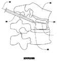
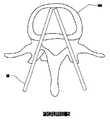
種々の図面を参照して観察され得るように、本発明は、海綿質組織17のような骨組織中に規定される腔74中の一時的または永久的配置のための離脱可能な半伸展性構造とともに、少なくとも1つの管腔またはその他の長く延びる通路を有するカテーテル67、好ましくは多管腔カテーテル67を含む。本発明はさらに、制限されないで、骨粗鬆症、骨粗鬆症で骨折した骨幹端および骨端骨、骨粗鬆症椎骨本体、腫瘍に起因する椎骨本体の骨折、特に円形細胞腫瘍、長骨の骨端の虚血壊死、特に近位大腿骨、遠位大腿骨および/または近位上腕骨の虚血壊死、および内分泌状態、転移性腫瘍から生じる欠陥、頸部、胸郭、腰椎のような長骨骨折(すなわち、外傷または自然に生じる骨骨折または骨構造のその他の局所的歪み)、および仙椎骨折などのような、外傷によるか、または疾患プロセスによって骨折した骨を処置する方法をさらに包含する。 As can be observed with reference to the various drawings, the present invention provides a removable semi-extensible for temporary or permanent placement in a cavity 74 defined in bone tissue such as cancellous tissue 17. Along with the structure, it includes a catheter 67, preferably a multi-lumen catheter 67, having at least one lumen or other elongated passage. The present invention further includes, but is not limited to, osteoporosis, metaphyseal and epiphyseal bone fractured with osteoporosis, osteoporotic vertebral body, vertebral body fracture caused by tumor, especially round cell tumor, ischemic necrosis of long bone epiphysis, In particular, ischemic necrosis of the proximal femur, distal femur and / or proximal humerus, and endocrine status, defects arising from metastatic tumors, long bone fractures such as neck, thorax, lumbar spine (ie trauma or Further included are methods of treating bone fractured by trauma or by disease processes, such as naturally occurring bone fractures or other local distortions of bone structure), and sacral fractures.
図6および7に最も良く示されるこの離脱可能な半伸展性構造49は、それが海綿質組織17の内部皮質壁内で選択された腔74の寸法にほぼ一致するような形状である。腔74は、制限されないで、穿孔、膨張可能な前駆体デバイスの挿入、およびその他の関連する方法のような当業者に知られた任意の適切な手順によって内部皮質壁内で簡単に識別され、そして/または規定され得る。この腔74の寸法は、制限されないでX線、CT走査または手術内CT撮像、超音波、コンピューター化断層撮影、MR/CT撮像表示、三次元可視化、光学的局在化、および磁気共鳴撮像(MRI)、または任意のその他の適切な撮像技法のような最小侵襲的撮像−案内技法を用いて予備決定され得る。好ましくは、半伸展性構造49の壁は、約10%〜約30%の伸展率を有し、この構造の、海綿質17または皮質骨の内壁のいずれかを含む腔74の壁との係合を提供する。 This removable semi-extensible structure 49 best shown in FIGS. 6 and 7 is shaped so that it approximately matches the size of the selected cavity 74 in the internal cortical wall of the cancellous tissue 17. The cavity 74 is easily identified within the inner cortical wall by any suitable procedure known to those skilled in the art, such as, without limitation, drilling, inserting an inflatable precursor device, and other related methods, And / or can be defined. The dimensions of this cavity 74 are not limited to X-ray, CT scanning or intraoperative CT imaging, ultrasound, computerized tomography, MR / CT imaging display, three-dimensional visualization, optical localization, and magnetic resonance imaging ( MRI), or any other suitable imaging technique, can be pre-determined using minimally invasive imaging-guided techniques. Preferably, the wall of the semi-extensible structure 49 has a stretch rate of about 10% to about 30%, and the engagement of this structure with the wall of the cavity 74 including either the cancellous 17 or the cortical bone inner wall. Provide a match.
図2に描写されるように、上記離脱可能な半伸展性構造49は、多管腔カテーテル67の管腔を通る適切な骨支持材料83の注入に際して拡大可能であり、この構造49は、その中の骨支持材料83の含有と維持、および海綿質組織17へのさらなる構造支持を提供する。この骨支持材料83の特徴は、この構造49が永久的移植であるか、またはこの構造49が骨骨折を治癒するに十分な持続時間の間一時的に移植されるかに依存して選択される。 As depicted in FIG. 2, the removable semi-extensible structure 49 can be expanded upon injection of a suitable bone support material 83 through the lumen of the multi-lumen catheter 67, which structure 49 The inclusion and maintenance of the bone support material 83 therein and further structural support to the cancellous tissue 17 are provided. The characteristics of the bone support material 83 are selected depending on whether the structure 49 is a permanent implant or is temporarily implanted for a duration sufficient to heal a bone fracture. The
永久的移植処置には、上記骨支持材料83は、従来の椎骨形成術またはKypohplasty手順で用いられるような、ポリメチルメタクリレート(「PMMA」)、または(制限されないで、デキストラン、ポリエチレン、カーボンファイバー、ポリビニルアルコール(PVA)、またはポリ(エチレンテレフタレート)(PET)を含む)その他の適切な生体材料代替物に基づくような、当該技術分野で知られるか、または開発される処方物から作製されるセメント様材料であり得る。より好ましくは、このセメント様材料は、PMMAである。PMMAの詳細な処方物は、当該技術分野で公知であり、そして骨インプラントで一般に用いられている。このような処方物は、制限されないで、例えば、米国特許第4,526,909号および同第6,544,324号に開示されるような処方物を含み、これらは本明細書中に参考として援用される。 For permanent implantation procedures, the bone support material 83 may be polymethylmethacrylate (“PMMA”), or (but not limited to, dextran, polyethylene, carbon fiber, as used in conventional vertebroplasty or Kypohplasty procedures. Cement made from formulations known or developed in the art, such as based on polyvinyl alcohol (PVA), or other suitable biomaterial substitutes (including poly (ethylene terephthalate) (PET)) It can be a like material. More preferably, the cement-like material is PMMA. Detailed formulations of PMMA are known in the art and are commonly used in bone implants. Such formulations include, but are not limited to, for example, those disclosed in US Pat. Nos. 4,526,909 and 6,544,324, which are incorporated herein by reference. Incorporated as.
本発明の主要な目的の1つは、骨折部位からのセメント様材料の脱出およびその生じる生理学的リスクを防ぐことである。この予防は、上記半伸展性構造49内のセメント様材料の含有および維持に起因して可能である。 One of the main objectives of the present invention is to prevent the escape of cementitious material from the fracture site and the resulting physiological risks. This prevention is possible due to the inclusion and maintenance of the cementitious material in the semi-extensible structure 49.
この半伸展性構造49内の骨支持材料83のさらなる含有および維持を提供するために、構造49には、図3および4に示されるような、シール可能なポート32が提供され得、これを通って、カテーテル67が半伸展性構造49と連通する。このポート32は、カテーテル67の離脱に際してシールされ得、骨支持材料83が構造49から漏失する事を防ぐ。この配列はさらに、構造49内の骨支持材料83の加圧された含有および維持を容易にする。さらに、シール可能なポート32はまた、生物学的流体の半伸展性構造49中への浸潤を防ぎ、それによって、内部半伸展性構造49の壁の腐食および分解を防ぐことにより、この構造の耐久性を改善する。あるいは、このカテーテル67は、骨支持材料83が硬化するような時間まで、半伸展性構造49に取り付けられたままであり得る。このような硬化時間は、PMMAが骨セメントとして用いられる場合、一般に、約2〜約10分を要する。一旦、このPMMAが硬化すると、カテーテル67は、次に、図3に示されるように、シール可能なポート32から材料が漏出するリスクを最小にして離脱され得る。図3中の骨組織17とは反対の矢印は、半伸展性構造49中への骨支持材料83の注入後、カテーテル67が移動し、そしてそれから外れる方向を示す。しかし、このプロセスは、潜在的に構造49を一時的に開いて残すので、この構造49中への生物学的流体の浸潤を避けるために必要な程度の注意を払うべきである。 To provide further containment and maintenance of bone support material 83 within this semi-extensible structure 49, the structure 49 may be provided with a sealable port 32, as shown in FIGS. Through, the catheter 67 communicates with the semi-extensible structure 49. This port 32 can be sealed upon removal of the catheter 67 to prevent the bone support material 83 from leaking from the structure 49. This arrangement further facilitates pressurized containment and maintenance of the bone support material 83 within the structure 49. In addition, the sealable port 32 also prevents infiltration of biological fluid into the semi-extensible structure 49, thereby preventing corrosion and decomposition of the walls of the internal semi-extensible structure 49. Improve durability. Alternatively, the catheter 67 may remain attached to the semi-extensible structure 49 until such time that the bone support material 83 is cured. Such setting times generally require from about 2 to about 10 minutes when PMMA is used as bone cement. Once the PMMA is cured, the catheter 67 can then be detached with minimal risk of material leaking from the sealable port 32, as shown in FIG. The arrow opposite the bone tissue 17 in FIG. 3 indicates the direction in which the catheter 67 moves and deviates after injection of the bone support material 83 into the semi-extensible structure 49. However, this process potentially leaves the structure 49 open temporarily, so the care necessary to avoid infiltration of biological fluid into the structure 49 should be taken.
本発明のデバイスはまた、海綿質17中の一時的移植のために利用され得、骨の構造を維持し、その一方骨折が治癒することを許容するための金属ロッド、ピンまたはスクリューの挿入に依存する同時手順と比較してより有利な骨設定技法を潜在的に提供する。この事例では、半伸展性構造49は、骨折が治癒する間、上記構造の強度および剛直性を維持するが、後の時間に排出のために骨支持材料83への接近を可能にするためのバルブを有するポートを要求し得る可能性があり得る。この事例では、シール可能なポート32はまた、カテーテル67の再取り付けを提供し、骨支持材料83の除去および骨17からのこの構造の離脱を許容する。 The device of the present invention can also be utilized for temporary implantation in cancellous material 17 for the insertion of metal rods, pins or screws to maintain bone structure while allowing fractures to heal. It potentially offers a more advantageous bone setting technique compared to dependent simultaneous procedures. In this case, the semi-extensible structure 49 maintains the strength and rigidity of the structure while the fracture heals, but to allow access to the bone support material 83 for ejection at a later time. It may be possible to require a port with a valve. In this case, the sealable port 32 also provides for reattachment of the catheter 67, allowing removal of the bone support material 83 and removal of the structure from the bone 17.
骨支持材料83の特徴は、それが、骨が治癒している間、剛直性または半剛直性状態をとり、そして一旦、この治癒プロセスが、内部支持がもはや必要でない点まで進行したなら、溶解、溶け、またはそうでなければ引き抜かれ得るように選択される。一旦、骨支持材料83が半伸展性構造49から排出されると、この構造49は、次いで、骨から離脱され得、骨17の最終治癒を許容する。この半伸展性構造49の金属ロッドまたはピンの利点に対する利点は、その伸展性が、それが離脱されるとき、海綿質17への最小外傷でその除去を容易にすることである。 The feature of the bone support material 83 is that it takes a rigid or semi-rigid state while the bone is healing, and once the healing process has progressed to the point where internal support is no longer needed, Selected so that it can be melted or otherwise pulled out. Once the bone support material 83 has been expelled from the semi-extensible structure 49, this structure 49 can then be detached from the bone, allowing final healing of the bone 17. The advantage of this semi-extensible structure 49 over the advantages of a metal rod or pin is that its extensibility facilitates its removal with minimal trauma to the cancellous 17 when it is detached.
上記半伸展性構造49は、例えば、制限されないで、ステンレス鋼、チタン、(例えば、ポリエステルおよびポリエチレン、ポリ乳酸およびこれらポリマーの互いとの、そしてその他のモノマーとのコポリマーのようなポリマー材料およびプラスチックのような)ポリマー、(例えば、縫合糸材料、Nitinol、またはこのような材料の組み合わせを含む、当業者に公知のような任意のその他の適切な材料のような)再吸収可能な合成材料である。好ましくは、半伸展性構造49は、処置のために選択された骨17の内部構造中に規定される腔74にほぼ一致するか、または適合するようなほぼ形状である生体適合性金属膜材料から形成される。Nitinolとして一般に知られるニッケルとチタンとの合金は、その証明された生体適合性、およびその生物学的環境の腐食影響に耐える能力の結果としてこの適用に良好に適している。この金属膜材料、そして特にNitinolのその他の望ましい性質は、その超弾性および形状記憶であり、これは、海綿質17中に規定された腔74中へのカテーテル67の挿入を容易にする。さらに、Nitinolのストレス−歪み特徴は、上記骨支持材料83と組み合わせて骨17にさらなる構造支持を提供するためにそれを優れた選択にする。 The semi-extensible structure 49 may be, for example, but not limited to, stainless steel, titanium, polymeric materials and plastics such as polyester and polyethylene, polylactic acid and copolymers of these polymers with each other and with other monomers Polymers (such as suture materials, Nitinol, or any other suitable material as known to those skilled in the art, including combinations of such materials) is there. Preferably, the semi-extensible structure 49 is a biocompatible metal membrane material that is generally shaped to substantially match or conform to a cavity 74 defined in the internal structure of the bone 17 selected for treatment. Formed from. The nickel and titanium alloy, commonly known as Nitinol, is well suited for this application as a result of its proven biocompatibility and its ability to withstand the corrosive effects of the biological environment. Another desirable property of this metal film material, and in particular Nitinol, is its superelasticity and shape memory, which facilitates insertion of the catheter 67 into the cavity 74 defined in the cancellous 17. Furthermore, Nitinol's stress-strain feature makes it an excellent choice to provide additional structural support to the bone 17 in combination with the bone support material 83 described above.
上記構造49の永久的配置を含む骨処置には、上記生体適合性材料には、適切な表面処理が提供され、海綿質17内の組み込みおよび治癒のために骨に都合の良いマトリックスを提供する。縫合糸の移植が一時的に回復させる手段である適用では、上記表面は、半伸展性構造49への海綿質17の取り込みを避け、そして半伸展性構造49への海綿質17の接着を減少するために調製され、それによって、離脱を容易にし、そして海綿質17への外傷を最小にする。 For bone treatment involving permanent placement of the structure 49, the biocompatible material is provided with a suitable surface treatment to provide a convenient matrix for the bone for incorporation and healing within the cancellous 17. . In applications where suture implantation is a temporary recovery means, the surface avoids the incorporation of cancellous 17 into the semi-extensible structure 49 and reduces the adhesion of the cancellous 17 to the semi-extensible structure 49. To facilitate release and minimize trauma to the cancellous 17.
半伸展性構造49についての広範な範囲の適用に起因して、上記骨支持材料83は、処置の基礎となる目的に基づいて選択される多くの材料を含み得る。この処置が、永久的骨支持のためである場合、骨支持材料83は、先に記載のPMMA処方物のようなセメント様材料を含み、これは、液体、ペーストまたはゲルとして注入され得、そして次に短時間内に硬化または堅くされる。セメント様材料が、半伸展性構造49内に含まれ、そして維持されるので、この材料が、含まれない適用によって遭遇するのと同じ生化学的環境に遭遇しないように、広範な範囲のセメント様材料が可能である。 Due to the wide range of applications for the semi-extensible structure 49, the bone support material 83 may include a number of materials that are selected based on the purpose underlying the procedure. If this treatment is for permanent bone support, the bone support material 83 includes a cement-like material such as the PMMA formulation described above, which can be injected as a liquid, paste or gel, and It is then cured or hardened within a short time. Since a cement-like material is contained and maintained within the semi-extensible structure 49, a wide range of cement is used so that this material does not encounter the same biochemical environment encountered by non-included applications. Various materials are possible.
上記処置が骨17の一時的支持のためである事例では、骨支持材料83は液体として注入され、支持のために必要な時間の間には液体のままであり、そして次に、手順が終了したとき、容易に引き抜かれ得る。代替の実施形態では、骨支持材料83は、柔軟なゲル様材料の形態であり得、骨構造のための支持およびエネルギー減衰を提供する。 In the case where the procedure is for temporary support of the bone 17, the bone support material 83 is injected as a liquid, remains liquid for the time required for support, and then the procedure ends. Can be easily pulled out. In an alternative embodiment, the bone support material 83 may be in the form of a soft gel-like material that provides support and energy attenuation for the bone structure.
疾患が骨の骨折の原因に寄与するか、またはその基礎である適用には、本発明のさらなる目的は、骨支持材料83が、この疾患の処置のためのキャリアとして供されることを企図する。本明細書中で企図される本発明のこの局面は、原因となる疾患状態の医薬による処置、放射線学的処置または熱処置を含む。 For applications where the disease contributes to or is the basis of bone fracture, a further object of the present invention contemplates that bone support material 83 is provided as a carrier for the treatment of this disease. . This aspect of the invention contemplated herein includes the treatment of a causative disease state with a medicament, radiological treatment or thermal treatment.
医薬による処置のレジメの事例では、金属膜材料の表面は、骨自体内から特定の疾患状態を標的にする時間放出医薬で含浸または被覆され得る。あるいは、この医薬は、上記構造49のために選択された半透過性生体適合性材料を通じて拡散され得、骨17の疾患または損傷を処置する。 In the case of a pharmaceutical treatment regime, the surface of the metal membrane material can be impregnated or coated with a time-release drug that targets a specific disease state from within the bone itself. Alternatively, the medicament can be diffused through the semipermeable biocompatible material selected for the structure 49 to treat a disease or injury of the bone 17.
放射線学的処置の事例では、この放射線学的処置物は、骨支持材料83と、混合物を半伸展性構造49中に、それがこの半伸展性構造49内に含まれ、そして維持されるように導入することにより混合される。この場合には、放射線学的処置物は、海綿質組織17への適切な曝露の後、半伸展性構造49から引き抜かれ得る。さらに、本発明は、構造49の一時的移植を企図するので、それはまた、放射線学的処置の間、またはすべての放射線学的手順の終了後に置換され得る。 In the case of a radiological procedure, the radiological treatment is such that the bone support material 83 and the mixture are contained in and maintained in the semi-extensible structure 49. To be mixed. In this case, the radiological treatment can be withdrawn from the semi-extensible structure 49 after appropriate exposure to the cancellous tissue 17. Furthermore, since the present invention contemplates temporary implantation of structure 49, it can also be replaced during radiological procedures or after completion of all radiological procedures.
熱処置は、骨支持材料83が半伸展性構造49中に導入されるとき、第1の例で提供され得る。骨支持材料83の温度は、半伸展性構造49中への導入の前に所望のレベル
調節され得る。あるいは、適切な温度は、選択された骨支持材料83の触媒反応によって達成され得る。骨組織17の再処置は、本明細書中に記載される選択された処置レジメの引き続く引き抜き、および再導入によってなされ得る。Thermal treatment may be provided in the first example when the bone support material 83 is introduced into the semi-extensible structure 49. The temperature of the bone support material 83 can be adjusted to a desired level prior to introduction into the semi-extensible structure 49. Alternatively, the appropriate temperature can be achieved by catalytic reaction of the selected bone support material 83. Retreatment of the bone tissue 17 can be done by subsequent withdrawal and reintroduction of the selected treatment regime described herein.
上記に記載される実施形態に、その広範な発明的概念から逸脱することなく変更がなされ得ることが当業者によって認識される。それ故、本発明が開示される特定の実施形態に制限されず、添付の特許請求の範囲によって規定される本発明の思想および範囲内の改変を包含することが意図されることが理解される。 It will be appreciated by those skilled in the art that changes may be made to the embodiments described above without departing from the broad inventive concept thereof. It is therefore to be understood that the invention is not limited to the particular embodiments disclosed, but is intended to encompass modifications within the spirit and scope of the invention as defined by the appended claims. .
Claims (29)
Translated fromJapanese処置されるべき骨組織中の内部領域を選択する工程;
該処置されるべき骨組織の内部領域中にデバイスを挿入する工程;および
処置の間に該デバイスを用いて該骨組織を内部で支持する工程、を包含する、方法。A method of treating disease or damaged bone tissue comprising:
Selecting an internal region in the bone tissue to be treated;
Inserting a device into an interior region of the bone tissue to be treated; and internally supporting the bone tissue with the device during a procedure.
該カテーテルを該半伸展性構造から離脱する工程;
前記シール可能なポートをシールする工程;および
加圧環境にある該構造内に前記骨支持材料を維持し、それによって、該骨支持材料が該構造内から押出すことを防ぎ、前記骨組織の一時的支持を提供する工程をさらに包含する、方法。9. The method of claim 8, wherein the semi-extensible structure is removable from the catheter:
Detaching the catheter from the semi-extensible structure;
Sealing the sealable port; and maintaining the bone support material within the structure in a pressurized environment, thereby preventing the bone support material from extruding from within the structure, and A method further comprising providing temporary support.
前記骨支持材料を引き抜く工程、をさらに包含する、請求項18に記載の方法。19. The method of claim 18, further comprising: reattaching the catheter to the sealable port; and withdrawing the bone support material.
カテーテルであって、それを通る少なくとも1つの内部通路を規定する主本体を備えるカテーテル;
拡大可能な半伸展性構造であって、内部スペースを規定する半伸展性構造;および
離脱可能なファスナーであって、該カテーテルを該半伸展性構造に離脱可能に連結するファスナーを備える、デバイス。A device for treating diseased or damaged bones:
A catheter comprising a main body defining at least one internal passage therethrough;
An expandable semi-extensible structure, comprising: a semi-extensible structure defining an interior space; and a releasable fastener, the fastener releasably connecting the catheter to the semi-extensible structure.
Applications Claiming Priority (3)
| Application Number | Priority Date | Filing Date | Title |
|---|---|---|---|
| US64196805P | 2005-01-07 | 2005-01-07 | |
| US60/641,968 | 2005-01-07 | ||
| PCT/US2006/000534WO2006074410A2 (en) | 2005-01-07 | 2006-01-09 | Three-dimensional implantable bone support |
Publications (2)
| Publication Number | Publication Date |
|---|---|
| JP2008526372Atrue JP2008526372A (en) | 2008-07-24 |
| JP5159320B2 JP5159320B2 (en) | 2013-03-06 |
Family
ID=36648227
Family Applications (1)
| Application Number | Title | Priority Date | Filing Date |
|---|---|---|---|
| JP2007550516AExpired - Fee RelatedJP5159320B2 (en) | 2005-01-07 | 2006-01-09 | 3D implantable bone support |
Country Status (12)
| Country | Link |
|---|---|
| US (1) | US20060155296A1 (en) |
| EP (1) | EP1833426A4 (en) |
| JP (1) | JP5159320B2 (en) |
| KR (1) | KR101303583B1 (en) |
| CN (1) | CN101123920B (en) |
| AR (1) | AR055833A1 (en) |
| AU (1) | AU2006203902B2 (en) |
| BR (1) | BRPI0606473A2 (en) |
| CA (1) | CA2592782C (en) |
| PE (1) | PE20060861A1 (en) |
| TW (1) | TW200640433A (en) |
| WO (1) | WO2006074410A2 (en) |
Cited By (2)
| Publication number | Priority date | Publication date | Assignee | Title |
|---|---|---|---|---|
| JP2011115631A (en)* | 2011-03-15 | 2011-06-16 | Hiromi Hayashi | Artificial joint |
| JP2014506809A (en)* | 2011-01-17 | 2014-03-20 | ノビタ・セラピューティクス・リミテッド・ライアビリティ・カンパニー | Block stent device and method of use |
Families Citing this family (53)
| Publication number | Priority date | Publication date | Assignee | Title |
|---|---|---|---|---|
| CA2363254C (en) | 1999-03-07 | 2009-05-05 | Discure Ltd. | Method and apparatus for computerized surgery |
| TWI235055B (en)* | 2003-05-21 | 2005-07-01 | Guan-Gu Lin | Filling device capable of removing animal tissues |
| TW587932B (en)* | 2003-05-21 | 2004-05-21 | Guan-Gu Lin | Removable animal tissue filling device |
| TW200511970A (en)* | 2003-09-29 | 2005-04-01 | Kwan-Ku Lin | A spine wrapping and filling apparatus |
| JP2008511422A (en)* | 2004-09-02 | 2008-04-17 | クロストゥリーズ・メディカル・インコーポレーテッド | Device and method for distraction of spinal disc space |
| US7955339B2 (en)* | 2005-05-24 | 2011-06-07 | Kyphon Sarl | Low-compliance expandable medical device |
| WO2007008794A2 (en)* | 2005-07-07 | 2007-01-18 | Crosstrees Medical, Inc. | Devices and methods for the treatment of bone fracture |
| WO2007062394A2 (en)* | 2005-11-23 | 2007-05-31 | Crosstrees Medical, Inc. | Devices and methods for the treatment of bone fracture |
| US7811290B2 (en) | 2006-04-26 | 2010-10-12 | Illuminoss Medical, Inc. | Apparatus and methods for reinforcing bone |
| US7806900B2 (en) | 2006-04-26 | 2010-10-05 | Illuminoss Medical, Inc. | Apparatus and methods for delivery of reinforcing materials to bone |
| US7879041B2 (en) | 2006-11-10 | 2011-02-01 | Illuminoss Medical, Inc. | Systems and methods for internal bone fixation |
| CA2669129C (en) | 2006-11-10 | 2014-09-16 | Illuminoss Medical, Inc. | Systems and methods for internal bone fixation |
| US7771476B2 (en) | 2006-12-21 | 2010-08-10 | Warsaw Orthopedic Inc. | Curable orthopedic implant devices configured to harden after placement in vivo by application of a cure-initiating energy before insertion |
| US8480718B2 (en)* | 2006-12-21 | 2013-07-09 | Warsaw Orthopedic, Inc. | Curable orthopedic implant devices configured to be hardened after placement in vivo |
| US20080268056A1 (en)* | 2007-04-26 | 2008-10-30 | Abhijeet Joshi | Injectable copolymer hydrogel useful for repairing vertebral compression fractures |
| US20080269897A1 (en)* | 2007-04-26 | 2008-10-30 | Abhijeet Joshi | Implantable device and methods for repairing articulating joints for using the same |
| WO2009036466A1 (en)* | 2007-09-14 | 2009-03-19 | Crosstrees Medical, Inc. | Material control device for inserting material into a targeted anatomical region |
| US9427289B2 (en) | 2007-10-31 | 2016-08-30 | Illuminoss Medical, Inc. | Light source |
| EP2214580B1 (en) | 2007-11-16 | 2013-05-22 | Synthes GmbH | Porous containment device for stabilization of vertebral compression fractures |
| US8403968B2 (en) | 2007-12-26 | 2013-03-26 | Illuminoss Medical, Inc. | Apparatus and methods for repairing craniomaxillofacial bones using customized bone plates |
| US20090297603A1 (en)* | 2008-05-29 | 2009-12-03 | Abhijeet Joshi | Interspinous dynamic stabilization system with anisotropic hydrogels |
| GB0813659D0 (en) | 2008-07-25 | 2008-09-03 | Smith & Nephew | Fracture putty |
| US8210729B2 (en) | 2009-04-06 | 2012-07-03 | Illuminoss Medical, Inc. | Attachment system for light-conducting fibers |
| US8512338B2 (en) | 2009-04-07 | 2013-08-20 | Illuminoss Medical, Inc. | Photodynamic bone stabilization systems and methods for reinforcing bone |
| EP2416721B1 (en)* | 2009-04-09 | 2013-07-10 | Synthes GmbH | Minimally invasive spine augmentation and stabilization system |
| EP2467098A4 (en) | 2009-08-19 | 2015-07-08 | Illuminoss Medical Inc | Devices and methods for bone alignment, stabilization and distraction |
| KR101159040B1 (en) | 2009-10-08 | 2012-06-21 | 최길운 | Instrument maintaining a space of the vertebra and vertebra fixation system of using same |
| US9358058B2 (en)* | 2012-11-05 | 2016-06-07 | Globus Medical, Inc. | Methods and apparatus for treating vertebral fractures |
| US11090092B2 (en)* | 2009-12-07 | 2021-08-17 | Globus Medical Inc. | Methods and apparatus for treating vertebral fractures |
| US9526538B2 (en)* | 2009-12-07 | 2016-12-27 | Globus Medical, Inc. | Methods and apparatus for treating vertebral fractures |
| US9326799B2 (en)* | 2009-12-07 | 2016-05-03 | Globus Medical, Inc. | Methods and apparatus for treating vertebral fractures |
| US8734458B2 (en)* | 2009-12-07 | 2014-05-27 | Globus Medical, Inc. | Methods and apparatus for treating vertebral fractures |
| WO2011075745A2 (en)* | 2009-12-18 | 2011-06-23 | Palmaz Scientific, Inc. | Interosteal and intramedullary implants and method of implanting same |
| FR2955480B1 (en)* | 2010-01-26 | 2012-01-06 | Christian Choux | THERACIC WALL OSTEOSYNTHESIS DEVICE |
| US8864711B2 (en)* | 2010-01-27 | 2014-10-21 | Warsaw Orthopedic, Inc. | Drug dispensing balloon for treating disc disease or pain |
| US9220554B2 (en)* | 2010-02-18 | 2015-12-29 | Globus Medical, Inc. | Methods and apparatus for treating vertebral fractures |
| US8684965B2 (en) | 2010-06-21 | 2014-04-01 | Illuminoss Medical, Inc. | Photodynamic bone stabilization and drug delivery systems |
| US9144501B1 (en) | 2010-07-16 | 2015-09-29 | Nuvasive, Inc. | Fracture reduction device and methods |
| US20120123481A1 (en)* | 2010-11-15 | 2012-05-17 | Lin Chih I | Bone fixation device |
| EP2654584A1 (en) | 2010-12-22 | 2013-10-30 | Illuminoss Medical, Inc. | Systems and methods for treating conditions and diseases of the spine |
| US11484318B2 (en) | 2011-01-17 | 2022-11-01 | Artio Medical, Inc. | Expandable body device and method of use |
| US20130023876A1 (en) | 2011-07-19 | 2013-01-24 | Illuminoss Medical, Inc. | Combination Photodynamic Devices |
| US8936644B2 (en) | 2011-07-19 | 2015-01-20 | Illuminoss Medical, Inc. | Systems and methods for joint stabilization |
| CA3049059C (en) | 2012-01-17 | 2023-03-07 | Metactive Medical, Inc. | Expandable body device and method of use |
| US8939977B2 (en) | 2012-07-10 | 2015-01-27 | Illuminoss Medical, Inc. | Systems and methods for separating bone fixation devices from introducer |
| US9687281B2 (en) | 2012-12-20 | 2017-06-27 | Illuminoss Medical, Inc. | Distal tip for bone fixation devices |
| US9539041B2 (en) | 2013-09-12 | 2017-01-10 | DePuy Synthes Products, Inc. | Minimally invasive biomaterial injection system |
| EP3193746A4 (en) | 2014-09-17 | 2018-10-31 | Metactive Medical, Inc. | Expandable body device and method of use |
| CN108261250B (en)* | 2016-12-30 | 2019-12-10 | 先健科技(深圳)有限公司 | Anti-endoleak stent graft system |
| AU2018239680A1 (en) | 2017-03-24 | 2019-10-10 | Artio Medical, Inc. | Medical devices comprising detachable balloons and methods of manufacturing and use |
| US11071572B2 (en) | 2018-06-27 | 2021-07-27 | Illuminoss Medical, Inc. | Systems and methods for bone stabilization and fixation |
| CN110478088A (en)* | 2019-07-25 | 2019-11-22 | 中国人民解放军总医院 | It is a kind of for large segmental bone defect treatment intramuscular at bone device |
| KR102825366B1 (en)* | 2023-04-05 | 2025-06-26 | 울산대학교 산학협력단 | Cage for spinal surgery |
Citations (4)
| Publication number | Priority date | Publication date | Assignee | Title |
|---|---|---|---|---|
| JPH10501710A (en)* | 1994-05-20 | 1998-02-17 | ディー. クスリッシュ、ステファン | Expandable fabric implant for stabilizing spinal motion segments |
| US20030212426A1 (en)* | 2002-05-08 | 2003-11-13 | Olson, Stanley W. | Tactical detachable anatomic containment device and therapeutic treatment system |
| US20040006341A1 (en)* | 2000-06-23 | 2004-01-08 | Shaolian Samuel M. | Curable media for implantable medical device |
| JP2004526525A (en)* | 2001-04-19 | 2004-09-02 | シンセス(ユーエスエイ) | Inflatable device and method for reducing fracture in bone and in spinal treatment |
Family Cites Families (80)
| Publication number | Priority date | Publication date | Assignee | Title |
|---|---|---|---|---|
| US4697584A (en)* | 1984-10-12 | 1987-10-06 | Darrel W. Haynes | Device and method for plugging an intramedullary bone canal |
| US4944749A (en)* | 1985-01-23 | 1990-07-31 | Hilton Becker | Implant and inflating construction |
| US4685447A (en)* | 1985-03-25 | 1987-08-11 | Pmt Corporation | Tissue expander system |
| US5888221A (en)* | 1992-08-11 | 1999-03-30 | Gelbard; Steven D. | Spinal stabilization implant system |
| US5397363A (en)* | 1992-08-11 | 1995-03-14 | Gelbard; Steven D. | Spinal stabilization implant system |
| US5584831A (en)* | 1993-07-09 | 1996-12-17 | September 28, Inc. | Spinal fixation device and method |
| US5480400A (en)* | 1993-10-01 | 1996-01-02 | Berger; J. Lee | Method and device for internal fixation of bone fractures |
| US6716216B1 (en)* | 1998-08-14 | 2004-04-06 | Kyphon Inc. | Systems and methods for treating vertebral bodies |
| ATE361028T1 (en)* | 1994-01-26 | 2007-05-15 | Kyphon Inc | IMPROVED INFLATABLE DEVICE FOR USE IN SURGICAL METHODS OF FIXATION OF BONE |
| WO1995020362A1 (en)* | 1994-01-26 | 1995-08-03 | Reiley Mark A | Improved inflatable device for use in surgical protocol relating to fixation of bone |
| US6241734B1 (en)* | 1998-08-14 | 2001-06-05 | Kyphon, Inc. | Systems and methods for placing materials into bone |
| US6248110B1 (en)* | 1994-01-26 | 2001-06-19 | Kyphon, Inc. | Systems and methods for treating fractured or diseased bone using expandable bodies |
| US20030032963A1 (en)* | 2001-10-24 | 2003-02-13 | Kyphon Inc. | Devices and methods using an expandable body with internal restraint for compressing cancellous bone |
| US6123715A (en)* | 1994-07-08 | 2000-09-26 | Amplatz; Curtis | Method of forming medical devices; intravascular occlusion devices |
| FR2724553B1 (en)* | 1994-09-15 | 1996-12-20 | Tornier Sa | EXTERNAL OR INTERNAL FIXER FOR THE REPAIR OF FRACTURES OR ARTHROPLASTIES OF THE SKELETON |
| AU2101495A (en)* | 1995-03-13 | 1996-10-02 | Steven D. Gelbard | Spinal stabilization implant system |
| AU6499596A (en)* | 1995-07-18 | 1997-02-18 | Edwards, Garland U. | Flexible shaft |
| EP0873145A2 (en)* | 1996-11-15 | 1998-10-28 | Advanced Bio Surfaces, Inc. | Biomaterial system for in situ tissue repair |
| EP1905392B1 (en)* | 1997-03-07 | 2011-05-18 | Kyphon SÀRL | System for percutaneous bone and spinal stabilization, fixation and repair |
| US6213916B1 (en)* | 1997-04-16 | 2001-04-10 | Transmisiones Tsp, S.A. De C.V. | Apparatus for operating a clutch in an automated mechanical transmission |
| US5972015A (en)* | 1997-08-15 | 1999-10-26 | Kyphon Inc. | Expandable, asymetric structures for deployment in interior body regions |
| NZ513472A (en)* | 1997-06-09 | 2002-12-20 | Kyphon Inc | Apparatus for treating fractured or diseased bone using plastically expandable bodies |
| US6048346A (en)* | 1997-08-13 | 2000-04-11 | Kyphon Inc. | Systems and methods for injecting flowable materials into bones |
| US6033411A (en)* | 1997-10-14 | 2000-03-07 | Parallax Medical Inc. | Precision depth guided instruments for use in vertebroplasty |
| US6309420B1 (en)* | 1997-10-14 | 2001-10-30 | Parallax Medical, Inc. | Enhanced visibility materials for implantation in hard tissue |
| US6224631B1 (en)* | 1998-03-20 | 2001-05-01 | Sulzer Spine-Tech Inc. | Intervertebral implant with reduced contact area and method |
| US6440138B1 (en)* | 1998-04-06 | 2002-08-27 | Kyphon Inc. | Structures and methods for creating cavities in interior body regions |
| US6267502B1 (en)* | 1998-04-10 | 2001-07-31 | Minrad Inc. | Alignment verification device and method of using the same with a visual light beam and an x-ray |
| US6719773B1 (en)* | 1998-06-01 | 2004-04-13 | Kyphon Inc. | Expandable structures for deployment in interior body regions |
| CA2333761C (en)* | 1998-06-01 | 2008-05-27 | Kyphon Inc. | Expandable preformed structures for deployment in interior body regions |
| US6395007B1 (en)* | 1999-03-16 | 2002-05-28 | American Osteomedix, Inc. | Apparatus and method for fixation of osteoporotic bone |
| US6770079B2 (en)* | 1999-03-16 | 2004-08-03 | American Osteomedix, Inc. | Apparatus and method for fixation of osteoporotic bone |
| AU6168699A (en)* | 1999-03-24 | 2000-10-09 | Parallax Medical, Inc. | Non-compliant system for delivery of implant material |
| US6520996B1 (en)* | 1999-06-04 | 2003-02-18 | Depuy Acromed, Incorporated | Orthopedic implant |
| US6419705B1 (en)* | 1999-06-23 | 2002-07-16 | Sulzer Spine-Tech Inc. | Expandable fusion device and method |
| ES2164548B1 (en)* | 1999-08-05 | 2003-03-01 | Probitas Pharma Sa | DEVICE FOR DOSAGE OF FRAGUABLE MASS FOR VERTEBROPLASTIA AND OTHER SIMILAR OSEOS TREATMENTS. |
| US6231610B1 (en)* | 1999-08-25 | 2001-05-15 | Allegiance Corporation | Anterior cervical column support device |
| CA2287112C (en)* | 1999-09-02 | 2008-02-19 | Kieran Murphy | Method and apparatus for strengthening vertebral bodies |
| US6764491B2 (en)* | 1999-10-21 | 2004-07-20 | Sdgi Holdings, Inc. | Devices and techniques for a posterior lateral disc space approach |
| US6733513B2 (en)* | 1999-11-04 | 2004-05-11 | Advanced Bioprosthetic Surfaces, Ltd. | Balloon catheter having metal balloon and method of making same |
| US6899716B2 (en)* | 2000-02-16 | 2005-05-31 | Trans1, Inc. | Method and apparatus for spinal augmentation |
| US6558390B2 (en)* | 2000-02-16 | 2003-05-06 | Axiamed, Inc. | Methods and apparatus for performing therapeutic procedures in the spine |
| US7014633B2 (en)* | 2000-02-16 | 2006-03-21 | Trans1, Inc. | Methods of performing procedures in the spine |
| US6740093B2 (en)* | 2000-02-28 | 2004-05-25 | Stephen Hochschuler | Method and apparatus for treating a vertebral body |
| AU5326701A (en)* | 2000-04-05 | 2001-10-23 | Kyphon Inc | Methods and devices for treating fractured and/or diseased bone |
| US6749614B2 (en)* | 2000-06-23 | 2004-06-15 | Vertelink Corporation | Formable orthopedic fixation system with cross linking |
| US6899713B2 (en)* | 2000-06-23 | 2005-05-31 | Vertelink Corporation | Formable orthopedic fixation system |
| DE10032220A1 (en)* | 2000-07-03 | 2002-01-24 | Sanatis Gmbh | Magnesium ammonium phosphate cements, their manufacture and use |
| US6641582B1 (en)* | 2000-07-06 | 2003-11-04 | Sulzer Spine-Tech Inc. | Bone preparation instruments and methods |
| US7018416B2 (en)* | 2000-07-06 | 2006-03-28 | Zimmer Spine, Inc. | Bone implants and methods |
| US6679886B2 (en)* | 2000-09-01 | 2004-01-20 | Synthes (Usa) | Tools and methods for creating cavities in bone |
| AU2001243287A1 (en)* | 2000-10-10 | 2002-04-22 | Vertx, Inc. | Method and appartus for treating a vertebral body |
| WO2002047587A2 (en)* | 2000-10-25 | 2002-06-20 | Sdgi Holdings, Inc. | Vertically expanding intervertebral body fusion device |
| US6613089B1 (en)* | 2000-10-25 | 2003-09-02 | Sdgi Holdings, Inc. | Laterally expanding intervertebral fusion device |
| US6503250B2 (en)* | 2000-11-28 | 2003-01-07 | Kamaljit S. Paul | Bone support assembly |
| US6454807B1 (en)* | 2000-11-30 | 2002-09-24 | Roger P. Jackson | Articulated expandable spinal fusion cage system |
| US6440170B1 (en)* | 2000-12-04 | 2002-08-27 | Roger P. Jackson | Threaded interbody device |
| US7008433B2 (en)* | 2001-02-15 | 2006-03-07 | Depuy Acromed, Inc. | Vertebroplasty injection device |
| US6595998B2 (en)* | 2001-03-08 | 2003-07-22 | Spinewave, Inc. | Tissue distraction device |
| US7156877B2 (en)* | 2001-06-29 | 2007-01-02 | The Regents Of The University Of California | Biodegradable/bioactive nucleus pulposus implant and method for treating degenerated intervertebral discs |
| CA2454373A1 (en)* | 2001-07-20 | 2003-01-30 | The Spineology Group, Llc | An expandable porous mesh bag device and its use for bone surgery |
| US20030050644A1 (en)* | 2001-09-11 | 2003-03-13 | Boucher Ryan P. | Systems and methods for accessing and treating diseased or fractured bone employing a guide wire |
| US6706069B2 (en)* | 2001-09-13 | 2004-03-16 | J. Lee Berger | Spinal grooved director with built in balloon |
| US7001342B2 (en)* | 2001-10-30 | 2006-02-21 | Movdice Holding, Inc. | Biopsy/access tool with integrated biopsy device and access cannula and use thereof |
| US6730092B2 (en)* | 2001-12-03 | 2004-05-04 | Pioneer Laboratories, Inc. | System and method for bone fixation |
| US6752809B2 (en)* | 2001-12-04 | 2004-06-22 | K2 Medical, Llc | System and method for reinforcing bone in preparation for screw implantation |
| US6755833B1 (en)* | 2001-12-14 | 2004-06-29 | Kamaljit S. Paul | Bone support assembly |
| US7008426B2 (en)* | 2001-12-14 | 2006-03-07 | Paul Kamaljit S | Bone treatment plate assembly |
| US6582439B1 (en)* | 2001-12-28 | 2003-06-24 | Yacmur Llc | Vertebroplasty system |
| US6733534B2 (en)* | 2002-01-29 | 2004-05-11 | Sdgi Holdings, Inc. | System and method for spine spacing |
| US6689132B2 (en)* | 2002-05-15 | 2004-02-10 | Spineco, Inc. | Spinal implant insertion tool |
| AU2003298670A1 (en)* | 2002-11-21 | 2004-06-18 | Sdgi Holdings, Inc. | Systems and techniques for intravertebral spinal stabilization with expandable devices |
| US20040186471A1 (en)* | 2002-12-07 | 2004-09-23 | Sdgi Holdings, Inc. | Method and apparatus for intervertebral disc expansion |
| TWI221091B (en)* | 2003-04-18 | 2004-09-21 | A Spine Holding Group Corp | Spine filling device |
| US20050010297A1 (en)* | 2003-05-08 | 2005-01-13 | Kuros Biosurgery Ag | Balloon technologies for tissue repair |
| WO2004103152A2 (en)* | 2003-05-16 | 2004-12-02 | Spine Wave, Inc. | Tissue distraction device |
| US6923813B2 (en)* | 2003-09-03 | 2005-08-02 | Kyphon Inc. | Devices for creating voids in interior body regions and related methods |
| US7618418B2 (en)* | 2004-04-16 | 2009-11-17 | Kyphon Sarl | Plate system for minimally invasive support of the spine |
| US7628800B2 (en)* | 2005-06-03 | 2009-12-08 | Warsaw Orthopedic, Inc. | Formed in place corpectomy device |
| EP2285312A4 (en)* | 2008-05-01 | 2014-03-12 | Columna Pty Ltd | Systems methods and apparatuses for formation and insertion of tissue prostheses |
- 2006
- 2006-01-06ARARP060100061Apatent/AR055833A1/enunknown
- 2006-01-06PEPE2006000048Apatent/PE20060861A1/ennot_activeApplication Discontinuation
- 2006-01-09CACA2592782Apatent/CA2592782C/enactiveActive
- 2006-01-09EPEP06717700Apatent/EP1833426A4/ennot_activeWithdrawn
- 2006-01-09WOPCT/US2006/000534patent/WO2006074410A2/enactiveApplication Filing
- 2006-01-09KRKR1020077015324Apatent/KR101303583B1/ennot_activeExpired - Fee Related
- 2006-01-09TWTW095100736Apatent/TW200640433A/enunknown
- 2006-01-09JPJP2007550516Apatent/JP5159320B2/ennot_activeExpired - Fee Related
- 2006-01-09CNCN2006800019105Apatent/CN101123920B/ennot_activeExpired - Fee Related
- 2006-01-09USUS11/328,345patent/US20060155296A1/ennot_activeAbandoned
- 2006-01-09BRBRPI0606473-6Apatent/BRPI0606473A2/ennot_activeApplication Discontinuation
- 2006-01-09AUAU2006203902Apatent/AU2006203902B2/ennot_activeCeased
Patent Citations (4)
| Publication number | Priority date | Publication date | Assignee | Title |
|---|---|---|---|---|
| JPH10501710A (en)* | 1994-05-20 | 1998-02-17 | ディー. クスリッシュ、ステファン | Expandable fabric implant for stabilizing spinal motion segments |
| US20040006341A1 (en)* | 2000-06-23 | 2004-01-08 | Shaolian Samuel M. | Curable media for implantable medical device |
| JP2004526525A (en)* | 2001-04-19 | 2004-09-02 | シンセス(ユーエスエイ) | Inflatable device and method for reducing fracture in bone and in spinal treatment |
| US20030212426A1 (en)* | 2002-05-08 | 2003-11-13 | Olson, Stanley W. | Tactical detachable anatomic containment device and therapeutic treatment system |
Cited By (4)
| Publication number | Priority date | Publication date | Assignee | Title |
|---|---|---|---|---|
| JP2014506809A (en)* | 2011-01-17 | 2014-03-20 | ノビタ・セラピューティクス・リミテッド・ライアビリティ・カンパニー | Block stent device and method of use |
| JP2014508574A (en)* | 2011-01-17 | 2014-04-10 | ノビタ・セラピューティクス・リミテッド・ライアビリティ・カンパニー | Detachable metal balloon delivery device and method |
| JP2014509881A (en)* | 2011-01-17 | 2014-04-24 | ノビタ・セラピューティクス・リミテッド・ライアビリティ・カンパニー | Ball stent device and method of use |
| JP2011115631A (en)* | 2011-03-15 | 2011-06-16 | Hiromi Hayashi | Artificial joint |
Also Published As
| Publication number | Publication date |
|---|---|
| US20060155296A1 (en) | 2006-07-13 |
| KR20070114113A (en) | 2007-11-29 |
| PE20060861A1 (en) | 2006-10-25 |
| KR101303583B1 (en) | 2013-09-11 |
| EP1833426A2 (en) | 2007-09-19 |
| AR055833A1 (en) | 2007-09-12 |
| TW200640433A (en) | 2006-12-01 |
| AU2006203902A1 (en) | 2006-07-13 |
| BRPI0606473A2 (en) | 2009-06-30 |
| WO2006074410A2 (en) | 2006-07-13 |
| JP5159320B2 (en) | 2013-03-06 |
| WO2006074410A3 (en) | 2007-10-18 |
| EP1833426A4 (en) | 2013-01-23 |
| CA2592782C (en) | 2012-03-27 |
| AU2006203902B2 (en) | 2011-09-22 |
| CN101123920A (en) | 2008-02-13 |
| CA2592782A1 (en) | 2006-07-13 |
| CN101123920B (en) | 2012-09-26 |
Similar Documents
| Publication | Publication Date | Title |
|---|---|---|
| JP5159320B2 (en) | 3D implantable bone support | |
| KR100828223B1 (en) | System and method for the treatment of vertebral bodies | |
| US8740954B2 (en) | Device and method for orthopedic fracture fixation | |
| JP5366966B2 (en) | Porous containment device and related method for stabilizing vertebral compression fractures | |
| US8986312B2 (en) | Device and method for introducing flowable material into a body cavity | |
| US9220554B2 (en) | Methods and apparatus for treating vertebral fractures | |
| US20030050644A1 (en) | Systems and methods for accessing and treating diseased or fractured bone employing a guide wire | |
| US20150190239A1 (en) | Biologic vertebral reconstruction | |
| US20090299373A1 (en) | Kyphoplasty banded balloon catheter | |
| KR20030029621A (en) | Systems and methods for treating vertebral bodies | |
| JP2013512761A (en) | Method and apparatus for treating vertebral fractures | |
| JP2004516855A (en) | Spine treatment device | |
| US20110190776A1 (en) | Interosteal and intramedullary implants and method of implanting same | |
| US20140336710A1 (en) | Device and method for orthopedic fracture fixation | |
| CN110522502A (en) | Method of performing a balloon kyphoplasty procedure using a spoon-shaped cannula | |
| RU2454961C1 (en) | Method of treating spine hemangiomas | |
| RU2573101C1 (en) | Method for transcutaneous repair of vertebral body | |
| Rosales | Kiva System in the Treatment of Vertebral Osteoporotic Compression Fractures | |
| UA53309A (en) | Method for surgical palliative treatment of backbone destructions |
Legal Events
| Date | Code | Title | Description |
|---|---|---|---|
| A621 | Written request for application examination | Free format text:JAPANESE INTERMEDIATE CODE: A621 Effective date:20080811 | |
| RD03 | Notification of appointment of power of attorney | Free format text:JAPANESE INTERMEDIATE CODE: A7423 Effective date:20101119 | |
| RD04 | Notification of resignation of power of attorney | Free format text:JAPANESE INTERMEDIATE CODE: A7424 Effective date:20101126 | |
| A131 | Notification of reasons for refusal | Free format text:JAPANESE INTERMEDIATE CODE: A131 Effective date:20110128 | |
| A601 | Written request for extension of time | Free format text:JAPANESE INTERMEDIATE CODE: A601 Effective date:20110316 | |
| A602 | Written permission of extension of time | Free format text:JAPANESE INTERMEDIATE CODE: A602 Effective date:20110324 | |
| A521 | Request for written amendment filed | Free format text:JAPANESE INTERMEDIATE CODE: A523 Effective date:20110714 | |
| A131 | Notification of reasons for refusal | Free format text:JAPANESE INTERMEDIATE CODE: A131 Effective date:20110909 | |
| A601 | Written request for extension of time | Free format text:JAPANESE INTERMEDIATE CODE: A601 Effective date:20111206 | |
| A602 | Written permission of extension of time | Free format text:JAPANESE INTERMEDIATE CODE: A602 Effective date:20111213 | |
| A521 | Request for written amendment filed | Free format text:JAPANESE INTERMEDIATE CODE: A523 Effective date:20120228 | |
| A02 | Decision of refusal | Free format text:JAPANESE INTERMEDIATE CODE: A02 Effective date:20120508 | |
| A521 | Request for written amendment filed | Free format text:JAPANESE INTERMEDIATE CODE: A523 Effective date:20120910 | |
| A911 | Transfer to examiner for re-examination before appeal (zenchi) | Free format text:JAPANESE INTERMEDIATE CODE: A911 Effective date:20120919 | |
| TRDD | Decision of grant or rejection written | ||
| A01 | Written decision to grant a patent or to grant a registration (utility model) | Free format text:JAPANESE INTERMEDIATE CODE: A01 Effective date:20121119 | |
| A61 | First payment of annual fees (during grant procedure) | Free format text:JAPANESE INTERMEDIATE CODE: A61 Effective date:20121211 | |
| R150 | Certificate of patent or registration of utility model | Ref document number:5159320 Country of ref document:JP Free format text:JAPANESE INTERMEDIATE CODE: R150 Free format text:JAPANESE INTERMEDIATE CODE: R150 | |
| FPAY | Renewal fee payment (event date is renewal date of database) | Free format text:PAYMENT UNTIL: 20151221 Year of fee payment:3 | |
| R250 | Receipt of annual fees | Free format text:JAPANESE INTERMEDIATE CODE: R250 | |
| R250 | Receipt of annual fees | Free format text:JAPANESE INTERMEDIATE CODE: R250 | |
| R250 | Receipt of annual fees | Free format text:JAPANESE INTERMEDIATE CODE: R250 | |
| R250 | Receipt of annual fees | Free format text:JAPANESE INTERMEDIATE CODE: R250 | |
| R250 | Receipt of annual fees | Free format text:JAPANESE INTERMEDIATE CODE: R250 | |
| R250 | Receipt of annual fees | Free format text:JAPANESE INTERMEDIATE CODE: R250 | |
| R250 | Receipt of annual fees | Free format text:JAPANESE INTERMEDIATE CODE: R250 | |
| R250 | Receipt of annual fees | Free format text:JAPANESE INTERMEDIATE CODE: R250 | |
| LAPS | Cancellation because of no payment of annual fees |