JP2008522950A - Glass laminated substrate with increased impact / static load strength - Google Patents
Glass laminated substrate with increased impact / static load strengthDownload PDFInfo
- Publication number
- JP2008522950A JP2008522950AJP2007546778AJP2007546778AJP2008522950AJP 2008522950 AJP2008522950 AJP 2008522950AJP 2007546778 AJP2007546778 AJP 2007546778AJP 2007546778 AJP2007546778 AJP 2007546778AJP 2008522950 AJP2008522950 AJP 2008522950A
- Authority
- JP
- Japan
- Prior art keywords
- glass
- core
- mpa
- psi
- residual
- Prior art date
- Legal status (The legal status is an assumption and is not a legal conclusion. Google has not performed a legal analysis and makes no representation as to the accuracy of the status listed.)
- Granted
Links
- 239000011521glassSubstances0.000titleclaimsabstractdescription160
- 239000000758substrateSubstances0.000titleclaimsabstractdescription105
- 230000003068static effectEffects0.000titledescription7
- 239000010410layerSubstances0.000claimsdescription160
- 239000011229interlayerSubstances0.000claimsdescription7
- 239000005340laminated glassSubstances0.000abstractdescription37
- 230000002829reductive effectEffects0.000abstractdescription4
- 238000000034methodMethods0.000description17
- 239000000463materialSubstances0.000description16
- 230000008569processEffects0.000description13
- 239000002985plastic filmSubstances0.000description7
- 230000006835compressionEffects0.000description5
- 238000007906compressionMethods0.000description5
- 239000004973liquid crystal related substanceSubstances0.000description5
- 239000006060molten glassSubstances0.000description5
- 239000002245particleSubstances0.000description4
- 230000008901benefitEffects0.000description3
- 238000007496glass formingMethods0.000description3
- 239000002346layers by functionSubstances0.000description3
- 239000000203mixtureSubstances0.000description3
- 229920000642polymerPolymers0.000description3
- 208000010392Bone FracturesDiseases0.000description2
- 206010017076FractureDiseases0.000description2
- 230000005540biological transmissionEffects0.000description2
- 230000015572biosynthetic processEffects0.000description2
- 230000007423decreaseEffects0.000description2
- 238000009792diffusion processMethods0.000description2
- 238000007499fusion processingMethods0.000description2
- 230000009477glass transitionEffects0.000description2
- 238000003475laminationMethods0.000description2
- 238000012986modificationMethods0.000description2
- 230000004048modificationEffects0.000description2
- 239000004033plasticSubstances0.000description2
- 229920003023plasticPolymers0.000description2
- BASFCYQUMIYNBI-UHFFFAOYSA-NplatinumChemical compound[Pt]BASFCYQUMIYNBI-UHFFFAOYSA-N0.000description2
- OAICVXFJPJFONN-UHFFFAOYSA-NPhosphorusChemical compound[P]OAICVXFJPJFONN-UHFFFAOYSA-N0.000description1
- 206010052428WoundDiseases0.000description1
- 208000027418Wounds and injuryDiseases0.000description1
- 239000000853adhesiveSubstances0.000description1
- 230000001070adhesive effectEffects0.000description1
- 230000002411adverseEffects0.000description1
- 230000004075alterationEffects0.000description1
- 238000005452bendingMethods0.000description1
- 230000015556catabolic processEffects0.000description1
- 238000000576coating methodMethods0.000description1
- 150000001875compoundsChemical class0.000description1
- 239000004020conductorSubstances0.000description1
- 239000000470constituentSubstances0.000description1
- 230000010485copingEffects0.000description1
- 239000012792core layerSubstances0.000description1
- 238000005520cutting processMethods0.000description1
- 238000006731degradation reactionMethods0.000description1
- 238000013461designMethods0.000description1
- 238000009826distributionMethods0.000description1
- 230000000694effectsEffects0.000description1
- 239000010408filmSubstances0.000description1
- 238000011010flushing procedureMethods0.000description1
- 239000012634fragmentSubstances0.000description1
- 238000003286fusion draw glass processMethods0.000description1
- 230000005484gravityEffects0.000description1
- 238000010348incorporationMethods0.000description1
- 238000005304joiningMethods0.000description1
- 230000000670limiting effectEffects0.000description1
- 238000004519manufacturing processMethods0.000description1
- 230000003287optical effectEffects0.000description1
- 230000005693optoelectronicsEffects0.000description1
- 230000036961partial effectEffects0.000description1
- 230000035699permeabilityEffects0.000description1
- 229910052697platinumInorganic materials0.000description1
- 239000002861polymer materialSubstances0.000description1
- 238000012545processingMethods0.000description1
- 230000001902propagating effectEffects0.000description1
- 239000003870refractory metalSubstances0.000description1
- 238000003860storageMethods0.000description1
- 238000005728strengtheningMethods0.000description1
- 238000005496temperingMethods0.000description1
- 238000012360testing methodMethods0.000description1
- 239000010409thin filmSubstances0.000description1
- 239000005341toughened glassSubstances0.000description1
- 238000002834transmittanceMethods0.000description1
Images


Classifications
- B—PERFORMING OPERATIONS; TRANSPORTING
- B32—LAYERED PRODUCTS
- B32B—LAYERED PRODUCTS, i.e. PRODUCTS BUILT-UP OF STRATA OF FLAT OR NON-FLAT, e.g. CELLULAR OR HONEYCOMB, FORM
- B32B17/00—Layered products essentially comprising sheet glass, or glass, slag, or like fibres
- B32B17/06—Layered products essentially comprising sheet glass, or glass, slag, or like fibres comprising glass as the main or only constituent of a layer, next to another layer of a specific material
- B—PERFORMING OPERATIONS; TRANSPORTING
- B32—LAYERED PRODUCTS
- B32B—LAYERED PRODUCTS, i.e. PRODUCTS BUILT-UP OF STRATA OF FLAT OR NON-FLAT, e.g. CELLULAR OR HONEYCOMB, FORM
- B32B13/00—Layered products comprising a a layer of water-setting substance, e.g. concrete, plaster, asbestos cement, or like builders' material
- B32B13/04—Layered products comprising a a layer of water-setting substance, e.g. concrete, plaster, asbestos cement, or like builders' material comprising such water setting substance as the main or only constituent of a layer, which is next to another layer of the same or of a different material
- C—CHEMISTRY; METALLURGY
- C03—GLASS; MINERAL OR SLAG WOOL
- C03B—MANUFACTURE, SHAPING, OR SUPPLEMENTARY PROCESSES
- C03B17/00—Forming molten glass by flowing-out, pushing-out, extruding or drawing downwardly or laterally from forming slits or by overflowing over lips
- C03B17/02—Forming molten glass coated with coloured layers; Forming molten glass of different compositions or layers; Forming molten glass comprising reinforcements or inserts
- C—CHEMISTRY; METALLURGY
- C03—GLASS; MINERAL OR SLAG WOOL
- C03B—MANUFACTURE, SHAPING, OR SUPPLEMENTARY PROCESSES
- C03B17/00—Forming molten glass by flowing-out, pushing-out, extruding or drawing downwardly or laterally from forming slits or by overflowing over lips
- C03B17/06—Forming glass sheets
- C03B17/064—Forming glass sheets by the overflow downdraw fusion process; Isopipes therefor
- C—CHEMISTRY; METALLURGY
- C03—GLASS; MINERAL OR SLAG WOOL
- C03B—MANUFACTURE, SHAPING, OR SUPPLEMENTARY PROCESSES
- C03B33/00—Severing cooled glass
- C03B33/02—Cutting or splitting sheet glass or ribbons; Apparatus or machines therefor
- C—CHEMISTRY; METALLURGY
- C03—GLASS; MINERAL OR SLAG WOOL
- C03B—MANUFACTURE, SHAPING, OR SUPPLEMENTARY PROCESSES
- C03B33/00—Severing cooled glass
- C03B33/07—Cutting armoured, multi-layered, coated or laminated, glass products
- C03B33/076—Laminated glass comprising interlayers
- C—CHEMISTRY; METALLURGY
- C03—GLASS; MINERAL OR SLAG WOOL
- C03C—CHEMICAL COMPOSITION OF GLASSES, GLAZES OR VITREOUS ENAMELS; SURFACE TREATMENT OF GLASS; SURFACE TREATMENT OF FIBRES OR FILAMENTS MADE FROM GLASS, MINERALS OR SLAGS; JOINING GLASS TO GLASS OR OTHER MATERIALS
- C03C17/00—Surface treatment of glass, not in the form of fibres or filaments, by coating
- C03C17/02—Surface treatment of glass, not in the form of fibres or filaments, by coating with glass
- C—CHEMISTRY; METALLURGY
- C09—DYES; PAINTS; POLISHES; NATURAL RESINS; ADHESIVES; COMPOSITIONS NOT OTHERWISE PROVIDED FOR; APPLICATIONS OF MATERIALS NOT OTHERWISE PROVIDED FOR
- C09K—MATERIALS FOR MISCELLANEOUS APPLICATIONS, NOT PROVIDED FOR ELSEWHERE
- C09K2323/00—Functional layers of liquid crystal optical display excluding electroactive liquid crystal layer characterised by chemical composition
- C09K2323/05—Bonding or intermediate layer characterised by chemical composition, e.g. sealant or spacer
- C09K2323/051—Inorganic, e.g. glass or silicon oxide
- C—CHEMISTRY; METALLURGY
- C09—DYES; PAINTS; POLISHES; NATURAL RESINS; ADHESIVES; COMPOSITIONS NOT OTHERWISE PROVIDED FOR; APPLICATIONS OF MATERIALS NOT OTHERWISE PROVIDED FOR
- C09K—MATERIALS FOR MISCELLANEOUS APPLICATIONS, NOT PROVIDED FOR ELSEWHERE
- C09K2323/00—Functional layers of liquid crystal optical display excluding electroactive liquid crystal layer characterised by chemical composition
- C09K2323/05—Bonding or intermediate layer characterised by chemical composition, e.g. sealant or spacer
- C09K2323/053—Organic silicon compound, e.g. organosilicon
- C—CHEMISTRY; METALLURGY
- C09—DYES; PAINTS; POLISHES; NATURAL RESINS; ADHESIVES; COMPOSITIONS NOT OTHERWISE PROVIDED FOR; APPLICATIONS OF MATERIALS NOT OTHERWISE PROVIDED FOR
- C09K—MATERIALS FOR MISCELLANEOUS APPLICATIONS, NOT PROVIDED FOR ELSEWHERE
- C09K2323/00—Functional layers of liquid crystal optical display excluding electroactive liquid crystal layer characterised by chemical composition
- C09K2323/06—Substrate layer characterised by chemical composition
- C09K2323/061—Inorganic, e.g. ceramic, metallic or glass
- G—PHYSICS
- G02—OPTICS
- G02F—OPTICAL DEVICES OR ARRANGEMENTS FOR THE CONTROL OF LIGHT BY MODIFICATION OF THE OPTICAL PROPERTIES OF THE MEDIA OF THE ELEMENTS INVOLVED THEREIN; NON-LINEAR OPTICS; FREQUENCY-CHANGING OF LIGHT; OPTICAL LOGIC ELEMENTS; OPTICAL ANALOGUE/DIGITAL CONVERTERS
- G02F1/00—Devices or arrangements for the control of the intensity, colour, phase, polarisation or direction of light arriving from an independent light source, e.g. switching, gating or modulating; Non-linear optics
- G02F1/01—Devices or arrangements for the control of the intensity, colour, phase, polarisation or direction of light arriving from an independent light source, e.g. switching, gating or modulating; Non-linear optics for the control of the intensity, phase, polarisation or colour
- G02F1/13—Devices or arrangements for the control of the intensity, colour, phase, polarisation or direction of light arriving from an independent light source, e.g. switching, gating or modulating; Non-linear optics for the control of the intensity, phase, polarisation or colour based on liquid crystals, e.g. single liquid crystal display cells
- G02F1/133—Constructional arrangements; Operation of liquid crystal cells; Circuit arrangements
- G02F1/1333—Constructional arrangements; Manufacturing methods
- G02F1/133302—Rigid substrates, e.g. inorganic substrates
- H—ELECTRICITY
- H01—ELECTRIC ELEMENTS
- H01J—ELECTRIC DISCHARGE TUBES OR DISCHARGE LAMPS
- H01J2217/00—Gas-filled discharge tubes
- H01J2217/38—Cold-cathode tubes
- H01J2217/49—Display panels, e.g. not making use of alternating current
- H01J2217/492—Details
- H01J2217/49264—Vessels
Landscapes
- Chemical & Material Sciences (AREA)
- Engineering & Computer Science (AREA)
- Materials Engineering (AREA)
- Organic Chemistry (AREA)
- Life Sciences & Earth Sciences (AREA)
- Chemical Kinetics & Catalysis (AREA)
- General Chemical & Material Sciences (AREA)
- Geochemistry & Mineralogy (AREA)
- Structural Engineering (AREA)
- Laminated Bodies (AREA)
- Joining Of Glass To Other Materials (AREA)
- Liquid Crystal (AREA)
Abstract
Translated fromJapaneseDescription
Translated fromJapanese本発明は電子基板に関し、さらに詳しくは、基板の耐静/衝撃荷重強度を高めるために基板の選択された層が残留圧縮応力または残留引っ張り応力を有する、例えばフラットパネルディスプレイに用いられるような、ガラス積層基板に関する。 The present invention relates to electronic substrates, and more particularly, selected layers of the substrate have residual compressive or residual tensile stress to increase the static / impact load strength of the substrate, such as used in flat panel displays, for example. The present invention relates to a glass laminated substrate.
ガラス基板は、例えば液晶ディスプレイ(LCD)などの、ディスプレイに用いられることが多い。LCDは、電卓、時計、ビデオゲーム、オーディオ及びビデオ機器、携帯型コンピュータ、さらには自動車のダッシュボードにおいて情報を表示するために益々普及してきている。LCDの品質及び大きさの改善により、LCDはテレビセット及びデスクトップコンピュータディスプレイに従来用いられていた陰極線管(CRT)の魅力的代替品になった。さらに、プラズマディスプレイ(PD)、電界放出ディスプレイ(FED)及び有機発光高分子材ディスプレイ(OLED)などの、別のタイプのフラットパネルディスプレイ(FPD)がLCDの代替として開発されている。 Glass substrates are often used in displays such as liquid crystal displays (LCDs). LCDs are becoming increasingly popular for displaying information in calculators, watches, video games, audio and video equipment, portable computers, and even automobile dashboards. Improvements in LCD quality and size have made it an attractive replacement for cathode ray tubes (CRTs) previously used in television sets and desktop computer displays. In addition, other types of flat panel displays (FPDs) have been developed as an alternative to LCDs, such as plasma displays (PD), field emission displays (FED) and organic light emitting polymer display (OLED).
いくつかのFPDでは、ピクセルアドレス指定のための導電体層、カラーフィルタ、LCDの液晶配向または配列層あるいはFED及びPDの蛍光体層などの、機能層を載せるために2枚のガラス板が用いられる。機能層を有する2枚のガラス板の間に、液晶化合物(LCD)、発光高分子材(OLED)またはプラズマ形成ガス(PD)が配される。 In some FPDs, two glass plates are used to carry functional layers, such as conductor layers for pixel addressing, color filters, LCD liquid crystal alignment or alignment layers, or FED and PD phosphor layers. It is done. A liquid crystal compound (LCD), a light emitting polymer material (OLED) or a plasma forming gas (PD) is disposed between two glass plates having a functional layer.
プラスチックシートによるガラス板の置換えが特許文献1に開示されている。プラスチックシートは、柔軟性(よって良好な耐クラック強度を与える)及び耐衝撃/静荷重強度により、ガラス板より薄くつくることができる。プラスチックシートはガラス板より小さい比重も有し、したがってプラスチック基板によるLCDはガラス基板によるLCDより軽く、薄い。 Patent Document 1 discloses replacement of a glass plate with a plastic sheet. Plastic sheets can be made thinner than glass plates due to flexibility (thus giving good crack resistance strength) and impact / static load strength. Plastic sheets also have a lower specific gravity than glass plates, so LCDs with plastic substrates are lighter and thinner than LCDs with glass substrates.
残念ながら、プラスチックシートにはディスプレイへの適用を制限する、ガラスシートより、低いガラス転移温度、低い可視光透過率及び高いガス透過率という3つの特性がある。低ガラス転移温度のためにプラスチックシートの最高使用温度が制限される。すなわち、プラスチックシートは、LCDおよびOLEDディスプレイに用いられる種類のa(アモルファス)-Siまたはp(多結晶)-SiベースのTET(薄膜トランジスタ)の作成に必要な、高い、300〜600℃の温度にさらされると、熱分解するであろう。低光透過率は画像の明るさを弱める。プラスチックシートのガス透過率はOLEDディスプレイに用いられる有機発光材料の劣化を生じさせ得る。そのような制限はディスプレイにおけるプラスチックの適用を制約する。
したがって、ガラスシートの利点を高められた強度とともに提供できるガラス積層基板が未だに必要とされている。バルクで形成することができ、続いてスクラップによるかなりの損失を受けずに寸法を小さくすることができる、強化ガラス積層基板も必要とされている。さらに、薄化し、したがって軽量化することができ、同時に高められた耐荷重強度を提供することができる、ガラス積層基板が必要とされている。実質的にあらかじめ定められた耐衝撃/静荷重強度を有するガラス積層基板も必要とされている。 Therefore, there is still a need for a glass laminated substrate that can provide the advantages of a glass sheet with increased strength. There is also a need for a tempered glass laminate substrate that can be formed in bulk and subsequently reduced in size without incurring significant losses due to scrap. Furthermore, there is a need for a glass laminate substrate that can be thinned and thus reduced in weight, while at the same time providing increased load bearing strength. There is also a need for a glass laminate substrate having a substantially predetermined impact / static load strength.
本発明のガラス積層基板は、基板の耐荷重強度を高めるために残留圧縮応力または残留引っ張り応力を有する、選択された層を有する。 The glass laminated substrate of the present invention has selected layers having residual compressive stress or residual tensile stress to increase the load bearing strength of the substrate.
本ガラス積層基板は、焦点面アレイ、光電子デバイス、光電池、光デバイス、フラットパネルディスプレイ並びにウエハ段階及び組立段階における集積回路などの、ただしこれらには限定されない、電子基板として用いることができる。 The present glass laminated substrate can be used as an electronic substrate such as, but not limited to, a focal plane array, an optoelectronic device, a photovoltaic cell, an optical device, a flat panel display, and an integrated circuit in a wafer stage and an assembly stage.
一般に、ガラス積層基板は透明ガラスコア及び一対の透明ガラススキン層を有し、コアはスキン層より高い熱膨張係数を有する。スキン層に対するコアの比厚及び熱膨張係数は、スキン層に残留圧縮応力を発生させ、コアに残留引っ張り応力を発生させるように選ばれる。残留応力は基板の耐荷重強度を高める。スキン層の圧縮応力及びコアの引っ張り応力は、許容できないレベルの基板破損または砕片発生をおこさずに、以後の基板のスクライビング及び分割を可能にするように選ぶことができる。 In general, a glass laminated substrate has a transparent glass core and a pair of transparent glass skin layers, and the core has a higher thermal expansion coefficient than the skin layer. The specific thickness and thermal expansion coefficient of the core relative to the skin layer are selected so as to generate a residual compressive stress in the skin layer and a residual tensile stress in the core. Residual stress increases the load bearing strength of the substrate. The compressive stress of the skin layer and the tensile stress of the core can be chosen to allow subsequent scribing and splitting of the substrate without unacceptable levels of substrate breakage or debris generation.
一構成において、ガラス積層基板は例えばフラットパネルディスプレイに用いることができ、基板は、間隔をおいて配置された第1の熱膨張係数を有する一対の透明ガラススキン層及びスキン層の間に配置された透明ガラスコアを有し、透明ガラスコアは、ガラススキン層がほぼ1000psi(6.9MPa)より大きい残留圧縮応力を有し、ガラスコアがほぼ4000psi(27.6MPa)より小さい残留引っ張り応力を有するように、第1の熱膨張係数より高い第2の熱膨張係数を有する。 In one configuration, the glass laminate substrate can be used, for example, in a flat panel display, the substrate being disposed between a pair of transparent glass skin layers and skin layers having a first coefficient of thermal expansion spaced apart. Transparent glass core, wherein the glass skin layer has a residual compressive stress greater than approximately 1000 psi (6.9 MPa) and the glass core has a residual tensile stress less than approximately 4000 psi (27.6 MPa). Thus, it has a 2nd thermal expansion coefficient higher than a 1st thermal expansion coefficient.
スキン層に少なくともほぼ4000(27.6MPa)の圧縮応力を保持し、コアにほぼ1000psi(6.9MPa)より小さい引っ張り応力を有するようにガラス積層基板が選ばれる構成もある。 In some configurations, the glass laminate substrate is selected so that the skin layer retains a compressive stress of at least approximately 4000 (27.6 MPa) and the core has a tensile stress of less than approximately 1000 psi (6.9 MPa).
別の構成において、ガラス積層基板はスキン層とコアの間に配置された少なくとも1つのガラス中間層を有する。スキン層、中間層及びコアを形成するガラスのそれぞれの、硬化点及び熱膨張係数を選ぶことにより、コアの残留引っ張り応力を下げ、スキン層の残留圧縮応力を維持または高めることができる。 In another configuration, the glass laminated substrate has at least one glass interlayer disposed between the skin layer and the core. The residual tensile stress of the core can be lowered and the residual compressive stress of the skin layer can be maintained or increased by selecting the curing point and the thermal expansion coefficient of each of the glass forming the skin layer, the intermediate layer and the core.
スキン層の残留圧縮応力及びガラスコアの残留引っ張り応力は、傷の発生及び傷の伝播に対する耐性を提供する蓄積エネルギーをガラス積層基板に生じさせ、蓄積エネルギーは、基板を破損させずに、あるいは粒子または砕片などの有害な汚染ガラス砕片を発生させずに、基板のスクライビング及び分割を可能にするに十分に低い。 Residual compressive stress in the skin layer and residual tensile stress in the glass core cause stored energy in the glass laminate substrate that provides resistance to scratch generation and propagation, and the stored energy can be used without damage to the substrate or particles. Or low enough to allow scribing and splitting of the substrate without generating harmful contaminated glass debris such as debris.
上述した全般的説明及び以下の詳細な説明はいずれも、本発明の実施形態を提示し、特許請求されるような本発明の本質及び特徴の理解のための概観または枠組みの提供が目的とされていることは当然である。添付図面は本発明のさらなる理解を提供するために含められ、本明細書に組み入れられて本明細書の一部をなす。図面は本発明の様々な例示的実施形態を示し、記述とともに本発明の原理及び動作の説明に役立つ。 Both the foregoing general description and the following detailed description present embodiments of the invention and are intended to provide an overview or framework for understanding the nature and characteristics of the invention as claimed. Of course. The accompanying drawings are included to provide a further understanding of the invention, and are incorporated in and constitute a part of this specification. The drawings illustrate various exemplary embodiments of the invention and together with the description serve to explain the principles and operations of the invention.
本発明は、フラットパネルディスプレイに使用するための(図3及び4の例に示されるような)ガラス積層基板60を含む。本明細書で用いられるような、術語「フラットパネルディスプレイ」は電子基板の一例であって、液晶ディスプレイ(LCD)、プラズマディスプレイ(PD)、電界放出ディスプレイ(FED)及び有機発光高分子材ディスプレイ(OLED)を含めることができるが、これらには限定されない。 The present invention includes a glass laminate substrate 60 (as shown in the examples of FIGS. 3 and 4) for use in flat panel displays. As used herein, the term “flat panel display” is an example of an electronic substrate, such as a liquid crystal display (LCD), a plasma display (PD), a field emission display (FED), and an organic light emitting polymer display ( OLED) can be included, but is not limited to these.
図1を参照すれば、(積層なしで示される)ガラスシート20,30が液晶材料で満たされている間隙40によって隔てられた、LCDの略図が与えられる。シート20,30の縁端は低弾性率高分子接着剤44で互いに封止され、比較的硬いフレーム(図示せず)に配される。拡散板46が所定の間隔でシート30から隔てておかれ、拡散板はバックライト源としてはたらく。 Referring to FIG. 1, a schematic illustration of an LCD is provided, in which
シート20は露出表面22及び間隙表面24を有し、シート30は間隙表面32及び露出表面34を有する。
図2に示されるように荷重Lが印加されると、表面22及び32は圧縮を受け、したがって比較的耐荷重強度が大きい。しかし、表面24及び表面34は、荷重の激烈さ並びに表面24及び34に見られる内在傷に依存して、シート20,30の破損をもたらし得る、強められた引っ張り応力を受ける。 When a load L is applied as shown in FIG. 2, the
一般に、ガラスシートはクラックを生じさせるに十分に大きな内部歪をつくる衝撃によって破壊され、ガラスの破壊は圧縮歪によるよりも引っ張り歪みにより容易におこる。したがって、衝撃による破壊は一般に引っ張り応力によると見なすことができる。本発明にしたがって作成されるようなガラス積層基板60は、基板への荷重印加にともなう引っ張り歪みに少なくともある程度対抗するために残留圧縮応力を用いる。以下でさらに説明するように、ガラス積層基板60の残留圧縮応力と残留引っ張り応力の関係は、スクライビングプロセス及び分割プロセスにおいて許容できないレベルの砕片(または基板破損)を発生させずに耐衝撃/静荷重強度を高めるために選ぶこともできる。 In general, a glass sheet is broken by an impact that creates an internal strain large enough to cause a crack, and the glass breaks more easily by tensile strain than by compression strain. Therefore, it can be regarded that the fracture due to impact is generally due to tensile stress. A
本発明のガラス積層基板60は、ガラスシート20,30の代りに用いて、露出表面及び間隙表面において高められた強度を与え、よって得られるディスプレイの衝撃/静荷重に耐える能力を高めることができる。 The laminated
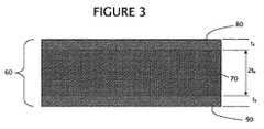
図3の例に示されるように、3層構成において、ガラス積層基板60は、間隔をおいて配置された一対のガラススキン層80,90に挟まれたガラスコア(層)70を有する。ガラス積層基板60は一般に、スキン層80,90の残留圧縮応力とコア70の残留引っ張り応力のあらかじめ定められた関係を有するように構成される。選ばれた構成において、スキン層80,90はガラスコア70と直接に接合される。 As shown in the example of FIG. 3, in a three-layer configuration, the glass laminated
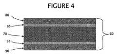
しかし、コア70とスキン層80,90の間に中間層を配置できることも当然である。そのような中間層には、ガラス中間層85,95を含めることができるが、これには限定されない。図4の例に見られるように、5層構造において、中間層85,95がスキン層80,90とガラスコア70の間に配置され、スキン層及び中間層は残留圧縮応力を有し、コアは残留引っ張り応力を有する。すなわち、スキン層80,90はコア70に直接に、一体として、コア70に接合させることができ、あるいは間接に、例えば、少なくとも1つの中間層85,95のそれぞれを介して、コアに接合させることができる。 However, it is natural that an intermediate layer can be disposed between the
ガラス積層基板60の3層(コア70及びスキン層80,90)構成において、例えば、スキン層80,90の応力σsは式(1):
で表すことができる。Can be expressed as
コア70の応力σcは式(2):
で表すことができる。Can be expressed as
ここで、Ec及びEsはそれぞれコアガラス及びスキンガラスの弾性率、νc及びνsはそれぞれコアガラス及びスキンガラスのポアソン比、αsは室温から硬化点(T*)までのスキン層ガラスの平均熱膨張係数、αcは室温から硬化点(T*)までのコアガラスの平均熱膨張係数、T*はコアガラスの硬化点とスキンガラスの硬化点の低い方(硬化点はガラス歪点より5℃高い温度と定義される)、tsはそれぞれのスキン層の厚さ、及びtcはコア厚の1/2である。Here, Ec and Es are the elastic modulus of the core glass and skin glass, νc and νs are Poisson's ratio of the core glass and skin glass, respectively, and αs is the skin layer from room temperature to the curing point (T* ). The average thermal expansion coefficient of glass, αc is the average thermal expansion coefficient of the core glass from room temperature to the curing point (T* ), and T* is the lower of the curing point of the core glass and the curing point of the skin glass (the curing point is glass) is defined as 5 ° C. temperature higher than the strain point), ts is the thickness of each skin layer, and tc is 1/2 of the core thickness.
式(1)及び(2)から、対称積層について、比σs/σcは:
と書くことができ、これは:
と書き換えることができる。Can be rewritten.
スキン層80,90のガラス及びコア70のガラスに対して適切な熱膨張係数(CTE)を選ぶことにより、スキン層に残留圧縮応力を形成することができ、コアに残留引っ張り応力を形成することができる。 By selecting an appropriate coefficient of thermal expansion (CTE) for the glass of the skin layers 80 and 90 and the glass of the core 70, a residual compressive stress can be formed in the skin layer and a residual tensile stress can be formed in the core. Can do.
式(1)及び(2)にしたがって、コア70及びスキン層80,90の厚さ並びにそれぞれの硬化点及びCTEを制御することにより、残留応力(スキン層の圧縮応力及びコアの引っ張り応力)の大きさを設定することができる。 Residual stress (skin layer compressive stress and core tensile stress) is controlled by controlling the thickness of the
一般に、スキン層80,90のガラス材料はコアガラス材料のCTEより小さいCTEを有する。有利な構成の1つではほぼ35%以内のスキン層CTE及びコアCTEが用いられるが、以下の実施例で実証されるように、スキンガラスとコアガラスの間の様々なCTE差のいずれをも用い得ることは当然である。 Generally, the glass material of skin layers 80, 90 has a CTE that is less than the CTE of the core glass material. One advantageous configuration uses skin layers CTE and core CTE within approximately 35%, but as demonstrated in the examples below, any of the various CTE differences between the skin glass and the core glass. Of course, it can be used.
実施例1:
実施例2:
実施例3:
弾性率Es及びEcが10.3×10⁶psi(ポンド/平方インチ)(7.1×104MPa),ポアソン比νs及びνcが0.22で、T*=671℃,αc=37.8×10−7,αs=31.8×10−7,tc=0.30mm,ts=0.05mmの代表的なガラス積層基板60は、4400psi(30.3MPa)のスキン層の残留圧縮応力及び725psi(5MPa)のコア70の内部引っ張り応力を与える。そのような積層は、工業界で既知のリングオンリング強度試験で測定すると、対応する無積層コアよりほぼ10%〜25%高い表面強度を有する。ほぼ1000psi(6.9MPa)より小さい内部引っ張り応力により、かなりの破砕リスクをおかさず、またはガラス表面を汚染し得るかなりのガラス粒子を生成させずに、ガラス積層基板のスクライビング及び切分けが可能となることがわかった。Elastic modulus Es and Ec of 10.3 × 10⁶ psi (7.1 × 10⁴ MPa), Poisson's ratio νs and νc of 0.22, T* = 671 ° C., A typical glass laminated
ガラス積層基板60の、許容できないレベルの砕片の発生または基板の破損をおこすことのない、スクライビング及び分割はコア70の4000psi(27.6MPa)もの高い引っ張り応力があっても満足に行い得ると考えられる。しかし、コア70の残留引っ張り応力が小さくなるとともに砕片発生及び基板破損の量が少なくなるから、コア70の残留引っ張り応力は、約2000psi(13.8MPa)より小さいことが望ましく、約1500psi(10.3MPa)より小さいことがさらに望ましい。ほぼ1000psi(6.9MPa)より小さく、ほぼ750psi(5.2MPa)より小さいことが有益な、コア70の残留引っ張り応力により、スクライビング及び分割プロセス中の許容できるレベルの砕片発生及び基板破損(破砕)を与えると同時に、耐衝撃/静荷重強度を高めるに十分なスキン層80,90の残留圧縮応力が可能になると考えられる。 The scribing and splitting of the
したがって、スキン層80,90の残留圧縮応力はほぼ3000〜15000psi(20.7〜103.4MPa)の範囲にあることが有利であり、ガラスコア70の引っ張り応力は、ほぼ4000psi(27.6MPa)より小さく、約2000psi(13.8MPa)より小さくことが有利であり、選ばれた構成ではほぼ1500psi(10.3MPa)より小さいような、破砕またはかなりの砕片発生をおこさずにガラス積層基板60のスクライビング及び分割を可能にするレベル以下に維持される。 Therefore, it is advantageous that the residual compressive stress of the skin layers 80 and 90 is in the range of about 3000 to 15000 psi (20.7 to 103.4 MPa), and the tensile stress of the
コア70の許容できる残留引っ張り応力は、コアの特定の組成により、またスキン層80,90のガラスの特定の組成によっても、少なくともある程度決定され、したがって、残留引っ張り応力を変えても優れた結果を得ることができる。さらに、残留引っ張り応力に対する残留圧縮応力の絶対値の比はほぼ2からほぼ20の範囲とすることができ、残留引っ張り応力はほぼ4000psi(27.6MPa)より小さく、1500psi(10.3MPa)より小さいことがさらに一層有利である。 The acceptable residual tensile stress of the
適切なガラス組成及びコア/スキン層の厚さ比を選ぶことによって、スキン層80,90の残留圧縮応力を約9,000psi(62.01MPa)とすることができ、よってガラス積層基板60の表面強度をほぼ50%高めることができる。 By choosing an appropriate glass composition and core / skin layer thickness ratio, the residual compressive stress of the skin layers 80, 90 can be about 9,000 psi (62.01 MPa), thus the surface of the
スキン層80,90の圧縮応力を(コア70の残留引っ張り応力と少なくともある程度バランスをとって)最大化することによって最大化されたガラス積層基板60の強度が得られるが、そのような強度最大化ガラス積層基板60におけるエネルギーの放出により、スクライビング及び分割プロセスにおいてかなりの基板破損率及び砕片発生が生じ得る。したがって、特定のガラス積層基板60の得られる強度を、スクライビング及び分割プロセス中にかなりの基板破損率または砕片発生をおこさずに最適に高めるように、残留圧縮応力及び残留引っ張り応力が選ばれる。 Maximizing the strength of the
説明の目的のため、及び利用できる文献に基づき、残留応力を有するガラスの50mm×50mm面積に対する砕片発生数の推定値は、N50=β(σc/KIC)4で与えられ、ここで、β=2.5×10-3α2/16であり、σcは中心引っ張り応力値、KICはガラスの破壊靭性であって、(ポアソン比ν=0.23に対して)α=16/15√3(1+ν)=0.5,β=39×10−6,N=39×10−6(σc/KIC)4,よってKIC=0.75MPa√mに対してN=123.2×10−6σc4/m2である。For illustrative purposes and based on available literature, an estimate of the number of fragments generated for a 50 mm × 50 mm area of glass with residual stress is given by N50 = β (σc / KIC )4 , where aβ = 2.5 × 10 -3 α 2 /16, the sigmac central tensile stressvalues, K IC is a fracture toughness of the glass, (relative to the Poisson's ratio ν = 0.23) α = 16 / 15√3 (1 + ν) = 0.5, β = 39 × 10−6 , N = 39 × 10−6 (σc / KIC )4 , and therefore KIC = 0.75 μm for N = 123.2 × 10⁻⁶ σc4 / m2 .
したがって、そのようなコアの様々な引っ張り応力についての砕片数Nは、
で与えられる。Given in.
厚さ0.7mm(代表的なフラットパネルディスプレイ寸法)の例示的な3層−1m×1mガラス積層基板60は形成された縁端に沿って1平方インチ(6.45cm2)を若干こえる表面積を有する。粒子の破片は存在しないから、スクライビング及び分割プロセスに対して1平方インチ(6.45cm2)当り1個ないしそれ以下の粒子発生を維持するためには、ほぼ2000psi(13.8MPa)のコア70の残留引っ張り応力が勧められる。スクライビング及び分割プロセス中に許容できる砕片発生及び基板破損率を示すため、ほぼ4000psi(27.6MPa)までの残留引っ張り応力をコア70に与えるように、ガラス積層基板60を構成できることは当然である。An exemplary 3-layer-1 m × 1 m
コア70の要件を満たすガラス材料がコーニング(Corning)コード1737ガラスであることがわかり、スキン層80,90の要件を満たすガラス材料がコーニングで製造されたEAGLE2000(商標)ガラスであることがわかった。選ばれた構成において、ガラスは一致するかまたは同等の屈折率を有することができる。スキン厚がほぼ0.02mmから0.2mmの積層に用いた場合に、これらの材料はディスプレイの取扱い、組立及び寿命中の表面損傷に対する十分な保護を提供することがわかった。 It was found that the glass material meeting the requirements of the core 70 was Corning code 1737 glass, and the glass material meeting the requirements of the skin layers 80, 90 was found to be EAGLE 2000 ™ glass manufactured by Corning. . In the chosen configuration, the glasses can match or have an equivalent refractive index. These materials have been found to provide sufficient protection against surface damage during handling, assembly and life of the display when used in laminates with skin thicknesses of approximately 0.02 mm to 0.2 mm.
ディスプレイへの組込みに向けられるガラス積層基板60については、重量の最小化が一要因になる。したがって、フラットパネルディスプレイ用途に関してガラス積層基板60は約2.0mmより薄い厚さを有することになり、ほぼ1.5mmより薄くすることができ、代表的な厚さは約1.1mmないしそれより薄く、スキン層80,90(及び、用いられる場合は中間層85,95)及びコア70は実質的に平坦な積層を形成する。携帯型フラットパネルディスプレイについては重量の最小化が第一義的な要件であることが多く、したがってガラス積層基板60の厚さはほぼ0.4mmからほぼ0.6mmであることが多い。テレビまたはデスクトップディスプレイなどの据置型フラットパネルディスプレイについては、ガラス積層基板60はほぼ0.7mmの厚さを有することができる。 For the glass laminated
一般に、フラットパネルディスプレイに使用するために作成されたガラス積層基板の総厚はほぼ0.4mmとほぼ1.1mmの間とすることができよう。スキン層80,90の厚さは総基板厚のほぼ8%と15%の間に選ばれ、スキン層厚のさらに最適な厚さは総基板厚のほぼ10%である。したがって、ガラス積層基板60は一般に薄すぎてガラスの焼き戻しができない厚さを有するが、残留応力によって高められた強度を与える。したがって、ガラス積層基板60は焼き戻しされないガラスで構成することができる。 In general, the total thickness of a glass laminate made for use in a flat panel display could be between approximately 0.4 mm and approximately 1.1 mm. The thickness of the skin layers 80, 90 is chosen between approximately 8% and 15% of the total substrate thickness, and a more optimal thickness for the skin layer thickness is approximately 10% of the total substrate thickness. Therefore, the glass laminated
本発明のガラス積層基板はガラスの傷発生及び傷伝播にも対処して改善された耐損傷強度をもつ基板を提供する。詳しくは、図3の例のガラス積層基板60は、スキン層が残留圧縮応力の大きさによって損傷に一層耐えるような、残留圧縮応力をもつスキン層80,90を提供する。例えば、また本開示の範囲を限定することなく、スキン層80,90に5000psi(34.5MPa)の表面圧縮応力をもつガラス積層基板60に対して傷をつけるには、非積層ガラスに同じ大きさの傷をつけるに必要な応力に比較して、さらに5000psi(34.5MPa)の応力が必要である。したがって、本発明のガラス積層基板は、LCDなどのフラットパネルディスプレイの作成の取扱い/処理工程中に損傷を受け難いであろう。さらに、残留応力の結果、ガラス積層基板60の永久的強化効果が得られる。すなわち、ガラス積層基板60にクラックを伝播させるに必要なレベルと同じレベルの引っ張り応力を生成するには、スキン層の残留圧縮応力を上回る応力が必要であろう。ここでも、スキン層に5000psi(34.5MPa)の残留圧縮応力をもつ本例を用いれば、積層ガラス基板面内でクラックを伝播させるには非積層ガラス面内に比べて5000psi(34.5MPa)大きい引っ張り応力が必要である。 The glass laminated substrate of the present invention provides a substrate having improved damage resistance by coping with the occurrence of scratches and propagation of scratches in glass. Specifically, the glass laminated
一般に、スキン層80,90のそれぞれは同じ厚さを有する同じ材料からなり、したがってコア70に関して対称な応力を与える。同様に、5層構成において、中間層85,95のそれぞれは同じ厚さを有する同じ材料からなり、したがってコア70に関して対称な応力を与える。すなわち、スキン層80,90(または中間層85,95)の残留圧縮応力は実質的に等しくなり得る。しかし、与えられたコア70上のスキン層80,90(及び/または中間層85,95)を異なる材料、CTEまたは厚さをもつ層とし得ることは当然であり、これは荷重が非対称な用途に対して有利になり得る。例えば、一方のスキン層の厚さを2倍にすることにより、ガラス積層基板60は、ラック保管時のような、水平方向での曲がりに対して高められた耐力を示すことができる。そのような非対称構造においては、垂直方向に配置される際に残留応力が定向曲がりを生じさせ得る。したがって、協同するガラス積層基板60は、そのような非対称残留応力に打ち勝つかまたはそれを補償するために、フレームで固定して保持することができる。すなわち、スキン層の非対称残留応力は、例えばほぼ10%のような、あらかじめ定められたレベルに設定することができる。一構成において、スキン層80,90の相互の残留圧縮応力はほぼ20%以内であり、ほぼ5%以内であるように、ほぼ10%以内であることが有利である。 In general, each of the skin layers 80, 90 are made of the same material having the same thickness, and therefore provide a symmetrical stress with respect to the
(図4に例示されるような)中間層85,95を有するガラス積層基板60の構成において、ガラスコア70の引っ張り応力は、スキン層80,90の残留圧縮応力に悪影響を及ぼさずに、さらに制限することができる。実施例4は、図4に見られる5層構成の代表的構成材料である。 In the configuration of the glass laminated
実施例4:中間層構成に対し、k=E/(1−ν)として:
ガラス積層基板60に中間層85,95を含めることの利点は、スキン層80,90に比較的大きな残留圧縮応力を維持しながらコア70の残留引っ張り応力を低くできる能力にある。 The advantage of including the
圧縮応力の値はガラスコア70の厚さに対する中間層85,95及びスキン層80,90のそれぞれの厚さに関係する。5層ガラス積層基板60の最終応力は次式:
で与えられる。Given in.
ここで、eは最も低い硬化点温度におけるそれぞれのガラスのΔL/Lを指し、添字c,i及びsはそれぞれコアガラス、中間層ガラス及びスキンガラスを指す。よってeoは:
で与えられる。Given in.
例えば、積層の総厚が0.7mmであり、中間層85,95及びスキン層80,90の厚さがいずれも0.0133mm(実施例3の構成と同じ)である場合:
tc=0.3234mm,
eo=5215×10−6,
σc=(5449−5215)×13.33=3119psi(21.5MPa) (コア内引っ張り応力)
σi=(2785−5215)×13.61=−33072psi(227.9 MPa)(中間層内圧縮応力)
σs=(2007−5215)×13.38=−42923psi(295.7 MPa)(スキン層内圧縮応力)
である。For example, when the total thickness of the laminate is 0.7 mm, and the thicknesses of the
tc = 0.3234 mm,
eo = 5215 ×10 -6,
σc = (5449-5215) × 13.33 = 3119 psi (21.5 MPa) (tensile stress in the core)
σi = (2785-5215) × 13.61 = −33072 psi (227.9 MPa) (compressive stress in the intermediate layer)
σs = (2007-5215) × 13.38 = −42923 psi (295.7 MPa) (compression stress in skin layer)
It is.
したがって、5層-3ガラス積層基板60は、コーニングコード0317ガラスコア70及びコーニングによる「EAGLE2000」ガラスのスキン層80,90を有する3層-2ガラス積層に比較して、11%低いコアの引っ張り応力及び11%低い中間層85,95の圧縮応力を有し、スキン層の圧縮応力は1%高い。すなわち、中間層85,95をもつ5層-3ガラス系はスキン層80,90の圧縮応力は維持しながらコア70の引っ張り応力をかなり低減するという利点を提供する。コア70の低減された内部引っ張り応力はスクライビング及び分割プロセス中の破砕及び砕片発生の低減に役立つ。 Thus, the 5-layer-3
ガラス積層基板60の3層構成に関連して述べたように、コア70,中間層85,95及びスキン層80,90の厚さ、それぞれの硬化点及びそれぞれのCTEを制御することにより、(スキン層及び中間層では圧縮、コアでは引っ張りの)残留応力の大きさを設計で設定することができる。すなわち、(スキン層80,90及び中間層85,95では圧縮、コア70では引っ張りの)残留応力の大きさを実質的にあらかじめ定めることができる。 As described in connection with the three-layer configuration of the glass laminated
ガラス積層基板60の残留応力は複数の層を構成層ガラスの最も低い硬化点より高い温度において接合することで形成される。(スキン層80,90に対するコア70,あるいはコア及びスキン層に対する中間層85,95などの)隣接層間で十分な接合を達成するためには、溶融ガラスをシート形態にする間に積層が行われることが有利であろう。ガラス形成の当業者には、そのような構造、そのような積層化引下げ及び積層化融合プロセスを達成するための複数の方法が既知である。 The residual stress of the glass laminated
一般に、スキン(及び中間層)ガラス及びコアガラスの融合引きがガラス積層基板60の形成の要件を満たす方法である。しかし、スロット引き、二重スロット引きまたはその他の適する接合方法のような別の方法をガラス積層基板60の形成に用い得ることは当然である。コア70及びスキン層80,90(及び中間層85,95)のガラス材料は、実質的に透明であり、歪みのない界面を形成するために同等な粘度を与えるように選ばれる。 In general, the fusion drawing of the skin (and intermediate layer) glass and the core glass is a method that satisfies the requirements for forming the glass laminated
代表的な積層化引下げプロセスまたはスロットプロセスにおいては、白金などの耐熱金属でつくられたスロットオリフィスに溶融ガラスが送り込まれる。積層化引下げ装置は、互いに並列に配置された複数のスロットオリフィスを有し、それぞれのオリフィスに別々の溶融ガラス流を送り込むことができる能力を有する。形成条件(一般に100000ポアズ(10000Pa秒))におけるガラスの流動性によって複数のガラス流はオリフィスをでる際に融合させられ、別々の層からなる一体ガラスシートを形成する。複数の層の厚さは個々のスロットオリフィスの寸法によって制御される。層の接合を補助するために下流のローラーがガラスシートに接し得ることは当然である。 In a typical laminated pull-down process or slot process, molten glass is fed into a slot orifice made of a refractory metal such as platinum. The laminated pulling down device has a plurality of slot orifices arranged in parallel with each other, and has the ability to feed separate molten glass streams to each orifice. Due to the flowability of the glass under forming conditions (typically 100,000 poise (10000 Pa seconds)), multiple glass streams are fused as they exit the orifice to form an integral glass sheet consisting of separate layers. The thickness of the layers is controlled by the dimensions of the individual slot orifices. Of course, a downstream roller can contact the glass sheet to assist in joining the layers.
一般に、積層化融合プロセスにおいては、米国特許第4214886号明細書に説明されているように、コア70及びスキン層80,90(及びガラス中間層85,95)が形成部材に沿って同時に流れてから、所望の厚さをもつ単一のガラス積層基板を形成するに適する粘度まで冷却されるような、制御可能なオーバーフロー分配システム及び形成部材によってガラス積層基板60が形成される。この明細書の開示は本明細書に参照として特に組み入れられる。 In general, in the laminated fusion process, the
対称形成プロセスの一例についての図5を参照すれば、コア70を形成するガラス及びスキン層80,90を形成するガラスが個別に溶融され、それぞれが適切な配送システムによって対応するオーバーフロー分配器170,180に配送される。オーバーフロー分配器180はオーバーフロー分配器170の上方に据えられ、オーバーフロー分配器180からのガラスはオーバーフロー分配器180の上端部分をこえて流れ、側面を流れ下って、オーバーフロー分配器180の上端部分の下で両側面上に適切な厚さの一様なフロー層を形成する。 Referring to FIG. 5 for an example of a symmetric forming process, the glass forming the
下段のオーバーフロー分配器170は分配器170に付帯するくさび形形成部材200を有する。形成部材200は、オーバーフロー分配器170の側壁と上端でつながり、延伸線において収斂下端で終端する、収斂側壁部分を有する。下段のオーバーフロー分配器170をオーバーフローする溶融ガラスは分配器壁に沿って下方に流れて、形成部材200の収斂外表面に隣接する初期ガラスフローを形成し、一方、分配器180をオーバーフローする溶融ガラスは上方から下方に上段分配器の壁にかけて流れて、コア層の外表面部分にかけて流れ、よって積層化ガラス流をつくる。形成部材200のそれぞれの収斂側壁からの2つの個々のガラス層は延伸線において1つに合されて融合し、単一の連続積層を形成する。コアガラスの2つの層は融合してコア70を形成し、スキン層を隔てる。 The
3層構成において、残留応力はスキン層80,90とコア70の間のCTEの差及びそれぞれの硬化点の差から得られる。スキンガラス及びコアガラスは高温で接合され、材料が周囲温度まで冷却されると、コアガラス(高CTE)はスキンガラス(低CTE)より大きく収縮しようとする。層は接合されているから、スキン層80,90に圧縮応力が発生し、引っ張り応力がコア70に発生する。 In the three-layer configuration, the residual stress is obtained from the difference in CTE between the skin layers 80, 90 and the
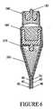
図6に見られるように、追加のオーバーフロー分配器及びそれに付帯する形成部材(及びそれぞれのガラス配送システム)を積み重ねることによって、ガラス積層基板60に、中間層85,95のような、付加層を組み込むことができる。すなわち、図4に示される5層ガラス積層基板60は、(スキン層80,90を形成する)オーバーフロー分配器180が(中間層85,95を形成する)オーバーフロー分配器185の上方にあり、オーバーフロー分配器185は(コア70を形成する)オーバーフロー分配器170の上方にある、図6に示されるシステムによって形成することができる。 As can be seen in FIG. 6, additional layers, such as
図6をまた参照すれば、オーバーフロー分配器180は、2つの異なるガラスを分配器から流し出し、よってスキン層90とは異なる材料のスキン層80の形成を可能にするための中央壁体185を有することができる。中央壁体182を有するオーバーフロー分配器180が示されているが、代りにオーバーフロー分配器185が中央壁体を有し、よって相異なる材料からなる中間層85及び95を与え得ることは当然である。 Referring again to FIG. 6,
形成部材を傾けることによるかまたは流量を変えて異ならせることによるか、あるいはこれらの組合せによるような、与えられたいずれかのオーバーフロー分配器(及び付帯する形成部材)の2つの側面上の相対ガラスフローの調節によって、非対称層厚を達成することができる。 Relative glass on the two sides of any given overflow distributor (and associated forming member), such as by tilting the forming member, by varying the flow rate, or by a combination thereof By adjusting the flow, an asymmetric layer thickness can be achieved.
寸法制御及び得られる初期ガラス表面状態により、融合プロセス、すなわちオーバーフロープロセスは、ガラス積層基板60を作成するための満足できる方法となる。 Depending on the dimensional control and the resulting initial glass surface condition, the fusing process, ie the overflow process, is a satisfactory method for making the
5層構成のガラス積層基板60の例に対する作成プロセスにおいては、スキンガラスのコーニング製「EAGLE2000」ガラスが初めに硬化し、無応力で収縮するであろう。コア70のガラス、コーニングコード0317はガラス積層基板60の中で最も軟らかいガラスであり、581℃の硬化点を有し、したがってコアガラスが581℃に冷却されるまではコアガラスに応力が生じない。しかし、中間層ガラスのコーニングコード7059は598℃の硬化点を有し、よって中間層ガラスはコアガラスより先に硬化して、張力を受け、積層60が598℃から581℃に冷却される間にスキンガラスに圧縮を誘起するであろう。ほぼ581℃において、コアガラスが硬化し始め、コアガラスが最も高いCTE値を有することから、コアガラスが最も大きな張力を受け、中間層85,95及びスキン層80,90のいずれにも正味の圧縮を誘起するであろう。 In the fabrication process for the example of a five layer
ガラス積層基板60が形成されてしまうと、機能層を含む、様々な層、コーティングまたはフィルムのいずれをもガラス積層基板に施すことができる。これらの付加層は一般に有意な残留圧縮応力または残留引っ張り応力を有することはないが、本明細書で論じたように、スキン層80,90(及び、用いられれば、中間層85,95)を、以降に基板上に被着される層を補償するように構成することができる。例えば、スキン層80,90及び/または中間層85,95の厚さ(または材料)を、そのような付加層を受け入れるための補償残留応力をつくるように選ぶことができる。すなわち、ガラス積層基板60は、以降の層がコア70の相対面にかかる圧縮応力の等化に貢献するような、不平衡表面圧縮応力を示すように形成することができる。 Once the glass laminated
本発明を本発明の特定の例示的実施形態に関して説明したが、上述の説明に鑑みれば、当業者には多くの別形、改変及び変型が明らかであろう。したがって、本発明は、添付される特許請求項の精神及び広汎な範囲内に入れば、そのような別形、改変、及び変型の全てを包含するとされる。 Although the present invention has been described with reference to specific exemplary embodiments of the invention, many alternatives, modifications, and variations will be apparent to those skilled in the art in view of the foregoing description. Accordingly, the present invention is intended to embrace all such alterations, modifications, and variations that fall within the spirit and broad scope of the appended claims.
60 ガラス積層基板
70 ガラスコア
80,90 スキン層
85,95 中間層60 Glass laminated
Claims (10)
Translated fromJapanese(a)第1の熱膨張係数を有する、間隔をおいて配置された一対の透明ガラススキン層、及び
(b)前記ガラススキン層の間に配置された、前記第1の熱膨張係数より高い第2の熱膨張係数を有する、透明ガラスコア、
を有し、
前記ガラススキン層がほぼ1000psi(6.9MPa)より大きい残留圧縮応力を有し、前記ガラスコアがほぼ4000psi(27.6MPa)より小さい残留引っ張り応力を有する、
ことを特徴とする積層基板。In laminated substrates,
(A) a pair of spaced apart transparent glass skin layers having a first coefficient of thermal expansion; and (b) higher than the first coefficient of thermal expansion disposed between the glass skin layers. A transparent glass core having a second coefficient of thermal expansion;
Have
The glass skin layer has a residual compressive stress greater than approximately 1000 psi (6.9 MPa) and the glass core has a residual tensile stress less than approximately 4000 psi (27.6 MPa);
A laminated substrate characterized by that.
スキン層熱膨張係数、スキン層硬化点及びほぼ1000psi(6.9MPa)より大きい残留圧縮応力を有する透明ガラススキン層、
コア熱膨張係数、コア硬化点及びほぼ4000psi(27.6MPa)より小さい残留引っ張り応力を有する透明ガラスコア、及び
前記ガラススキン層と前記ガラスコアの間に配置された、中間層熱膨張係数及び中間層硬化点を有する、透明ガラス中間層、
を有し、
前記中間層熱膨張係数が、前記スキン層熱膨張係数より小さく、前記コア熱膨張係数より大きいことを特徴とするフラットパネルディスプレイ用積層基板。In laminated substrates for flat panel displays,
A transparent glass skin layer having a skin layer coefficient of thermal expansion, a skin layer cure point, and a residual compressive stress greater than about 1000 psi (6.9 MPa);
A transparent glass core having a core coefficient of thermal expansion, a core cure point and a residual tensile stress less than about 4000 psi (27.6 MPa), and an intermediate layer coefficient of thermal expansion and an intermediate layer disposed between the glass skin layer and the glass core A transparent glass interlayer having a layer curing point,
Have
The flat panel display laminate substrate, wherein the intermediate layer thermal expansion coefficient is smaller than the skin layer thermal expansion coefficient and larger than the core thermal expansion coefficient.
Applications Claiming Priority (3)
| Application Number | Priority Date | Filing Date | Title |
|---|---|---|---|
| US11/011,323 | 2004-12-13 | ||
| US11/011,323US7201965B2 (en) | 2004-12-13 | 2004-12-13 | Glass laminate substrate having enhanced impact and static loading resistance |
| PCT/US2005/044664WO2006065657A2 (en) | 2004-12-13 | 2005-12-08 | Glass laminate substrate having enhanced impact and static loading resistance |
Related Child Applications (1)
| Application Number | Title | Priority Date | Filing Date |
|---|---|---|---|
| JP2014187566ADivisionJP5820039B2 (en) | 2004-12-13 | 2014-09-16 | Glass laminated substrate with increased impact / static load strength |
Publications (2)
| Publication Number | Publication Date |
|---|---|
| JP2008522950Atrue JP2008522950A (en) | 2008-07-03 |
| JP5649267B2 JP5649267B2 (en) | 2015-01-07 |
Family
ID=36584300
Family Applications (2)
| Application Number | Title | Priority Date | Filing Date |
|---|---|---|---|
| JP2007546778AExpired - Fee RelatedJP5649267B2 (en) | 2004-12-13 | 2005-12-08 | Glass laminated substrate with increased impact / static load strength |
| JP2014187566AExpired - Fee RelatedJP5820039B2 (en) | 2004-12-13 | 2014-09-16 | Glass laminated substrate with increased impact / static load strength |
Family Applications After (1)
| Application Number | Title | Priority Date | Filing Date |
|---|---|---|---|
| JP2014187566AExpired - Fee RelatedJP5820039B2 (en) | 2004-12-13 | 2014-09-16 | Glass laminated substrate with increased impact / static load strength |
Country Status (7)
| Country | Link |
|---|---|
| US (1) | US7201965B2 (en) |
| EP (2) | EP1836274B1 (en) |
| JP (2) | JP5649267B2 (en) |
| KR (1) | KR101180200B1 (en) |
| CN (1) | CN101076447B (en) |
| TW (1) | TWI284091B (en) |
| WO (1) | WO2006065657A2 (en) |
Cited By (46)
| Publication number | Priority date | Publication date | Assignee | Title |
|---|---|---|---|---|
| JP2009525941A (en)* | 2006-02-10 | 2009-07-16 | コーニング インコーポレイテッド | LAMINATED GLASS ARTICLE AND METHOD FOR PRODUCING THE SAME |
| WO2011099332A1 (en)* | 2010-02-12 | 2011-08-18 | 日本電気硝子株式会社 | Reinforced sheet glass and manufacturing method therefor |
| WO2011099333A1 (en)* | 2010-02-12 | 2011-08-18 | 日本電気硝子株式会社 | Reinforced sheet glass and manufacturing method therefor |
| WO2013065648A1 (en)* | 2011-10-31 | 2013-05-10 | 旭硝子株式会社 | Glass substrate, method for producing glass substrate, and cover glass |
| JP2013530123A (en)* | 2010-06-29 | 2013-07-25 | コーニング インコーポレイテッド | Multi-layer glass plate manufactured by co-stretching using overflow, downdraw and fusion methods |
| WO2013129400A1 (en)* | 2012-02-28 | 2013-09-06 | 旭硝子株式会社 | Laminated strengthened glass |
| JP2014500847A (en)* | 2010-11-30 | 2014-01-16 | コーニング インコーポレイテッド | Glass with surface and central region under compression |
| WO2014104050A1 (en)* | 2012-12-25 | 2014-07-03 | 日本電気硝子株式会社 | Reinforced plate glass and method for manufacturing same |
| JP2014521582A (en)* | 2011-07-25 | 2014-08-28 | コーニング インコーポレイテッド | Glass laminate reinforced by lamination and ion exchange and method for producing the same |
| JP2015512853A (en)* | 2012-02-29 | 2015-04-30 | コーニング インコーポレイテッド | Glass packaging to ensure container integrity |
| JP2015512852A (en)* | 2012-02-29 | 2015-04-30 | コーニング インコーポレイテッド | Low CTE alkali-free boroaluminosilicate glass composition and glass article comprising the same |
| JP2015512851A (en)* | 2012-02-29 | 2015-04-30 | コーニング インコーポレイテッド | High CTE potassium borosilicate core glass and glass article comprising the same |
| JP2015098412A (en)* | 2013-11-19 | 2015-05-28 | 日本電気硝子株式会社 | Strengthened glass plate and method for producing strengthened glass plate |
| JP2015516353A (en)* | 2012-02-29 | 2015-06-11 | コーニング インコーポレイテッド | High CTE opal glass composition and glass article comprising the same |
| JP2015520108A (en)* | 2012-05-24 | 2015-07-16 | コーニング インコーポレイテッド | Apparatus and method for controlling glass flow in laminated fusion |
| JP2016500628A (en)* | 2012-10-04 | 2016-01-14 | コーニング インコーポレイテッド | Article having glass layer and glass ceramic layer and method for producing the article |
| KR20160006715A (en)* | 2013-05-09 | 2016-01-19 | 코닝 인코포레이티드 | Alkali-free phosphoborosilicate glass |
| JP2016503386A (en)* | 2012-11-21 | 2016-02-04 | コーニング インコーポレイテッド | Cutting method of laminated tempered glass substrate |
| KR20160043008A (en)* | 2013-08-15 | 2016-04-20 | 코닝 인코포레이티드 | Intermediate to high cte glasses and glass articles comprising the same |
| JP2016513066A (en)* | 2013-02-26 | 2016-05-12 | コーニング インコーポレイテッド | Apparatus and method for forming glass sheet from core glass and clad glass |
| JP2016521675A (en)* | 2013-06-14 | 2016-07-25 | コーニング インコーポレイテッド | Laminate sealing sheet |
| JP2016523801A (en)* | 2013-06-14 | 2016-08-12 | コーニング インコーポレイテッド | Laminated glass article having a scratch-resistant surface |
| KR20160099673A (en)* | 2013-12-17 | 2016-08-22 | 코닝 인코포레이티드 | Laser cut composite glass article and method of cutting |
| JP2016528152A (en)* | 2013-08-15 | 2016-09-15 | コーニング インコーポレイテッド | Alkali-doped and alkali-free boroaluminosilicate glass |
| JP2016534963A (en)* | 2013-11-01 | 2016-11-10 | コーニング インコーポレイテッド | Apparatus and method for forming glass sheet |
| KR20160133501A (en)* | 2014-03-13 | 2016-11-22 | 코닝 인코포레이티드 | Glass Article and Method for Forming the Same |
| JP2017509579A (en)* | 2014-03-27 | 2017-04-06 | コーニング インコーポレイテッド | Glass article |
| JP2017525650A (en)* | 2014-08-28 | 2017-09-07 | コーニング インコーポレイテッド | LAMINATED GLASS PRODUCT WITH ION-EXCHANGEABLE CORE AND CLAD HAVING CONTRACT DIFFUSION AND METHOD FOR PRODUCING THE SAME |
| KR20170109638A (en)* | 2015-02-02 | 2017-09-29 | 코닝 인코포레이티드 | Method for strengthening the edges of laminated glass articles and laminated glass articles formed therefrom |
| JP2018526303A (en)* | 2015-06-02 | 2018-09-13 | コーニング インコーポレイテッド | Glass laminate with pane having glass-glass laminate structure |
| JP2020045278A (en)* | 2013-11-13 | 2020-03-26 | コーニング インコーポレイテッド | Laminated glass article and method for manufacturing the same |
| US11062986B2 (en) | 2017-05-25 | 2021-07-13 | Corning Incorporated | Articles having vias with geometry attributes and methods for fabricating the same |
| US11078112B2 (en) | 2017-05-25 | 2021-08-03 | Corning Incorporated | Silica-containing substrates with vias having an axially variable sidewall taper and methods for forming the same |
| US11114309B2 (en) | 2016-06-01 | 2021-09-07 | Corning Incorporated | Articles and methods of forming vias in substrates |
| US11130701B2 (en) | 2016-09-30 | 2021-09-28 | Corning Incorporated | Apparatuses and methods for laser processing transparent workpieces using non-axisymmetric beam spots |
| US11148225B2 (en) | 2013-12-17 | 2021-10-19 | Corning Incorporated | Method for rapid laser drilling of holes in glass and products made therefrom |
| US11345625B2 (en) | 2013-01-15 | 2022-05-31 | Corning Laser Technologies GmbH | Method and device for the laser-based machining of sheet-like substrates |
| US11542190B2 (en) | 2016-10-24 | 2023-01-03 | Corning Incorporated | Substrate processing station for laser-based machining of sheet-like glass substrates |
| US11554984B2 (en) | 2018-02-22 | 2023-01-17 | Corning Incorporated | Alkali-free borosilicate glasses with low post-HF etch roughness |
| US11556039B2 (en) | 2013-12-17 | 2023-01-17 | Corning Incorporated | Electrochromic coated glass articles and methods for laser processing the same |
| US11648623B2 (en) | 2014-07-14 | 2023-05-16 | Corning Incorporated | Systems and methods for processing transparent materials using adjustable laser beam focal lines |
| US11697178B2 (en) | 2014-07-08 | 2023-07-11 | Corning Incorporated | Methods and apparatuses for laser processing materials |
| US11713271B2 (en) | 2013-03-21 | 2023-08-01 | Corning Laser Technologies GmbH | Device and method for cutting out contours from planar substrates by means of laser |
| US11773004B2 (en) | 2015-03-24 | 2023-10-03 | Corning Incorporated | Laser cutting and processing of display glass compositions |
| US11774233B2 (en) | 2016-06-29 | 2023-10-03 | Corning Incorporated | Method and system for measuring geometric parameters of through holes |
| US12180108B2 (en) | 2017-12-19 | 2024-12-31 | Corning Incorporated | Methods for etching vias in glass-based articles employing positive charge organic molecules |
Families Citing this family (127)
| Publication number | Priority date | Publication date | Assignee | Title |
|---|---|---|---|---|
| JP2007212801A (en)* | 2006-02-10 | 2007-08-23 | Fujitsu Hitachi Plasma Display Ltd | Flat panel display, and display panel device with same |
| US7978281B2 (en) | 2008-09-16 | 2011-07-12 | General Dynamics Land Systems | Low stress mounting support for ruggedized displays |
| US9346699B2 (en) | 2008-10-06 | 2016-05-24 | Corning Incorporated | Method of making a glass laminate having controlled strength |
| DE102009025972B4 (en) | 2009-06-15 | 2018-12-27 | Sage Electrochromics, Inc. | Laminated glass pane and its use |
| JP2011034871A (en)* | 2009-08-04 | 2011-02-17 | Nec Lighting Ltd | Surface light-emitting device |
| US9302937B2 (en)* | 2010-05-14 | 2016-04-05 | Corning Incorporated | Damage-resistant glass articles and method |
| US8826693B2 (en)* | 2010-08-30 | 2014-09-09 | Corning Incorporated | Apparatus and method for heat treating a glass substrate |
| US20120192928A1 (en)* | 2011-01-27 | 2012-08-02 | Mark Francis Krol | Laminated pv module package |
| WO2012116316A1 (en) | 2011-02-25 | 2012-08-30 | Schott Corporation | Transparent laminate structures |
| US20120280368A1 (en)* | 2011-05-06 | 2012-11-08 | Sean Matthew Garner | Laminated structure for semiconductor devices |
| TWI547369B (en) | 2011-05-27 | 2016-09-01 | 康寧公司 | Glass-plastic laminate device, processing line and methods therefor |
| US9090505B2 (en) | 2011-07-15 | 2015-07-28 | Corning Incorporated | Microwave-based glass laminate fabrication |
| TWI691097B (en) | 2011-08-04 | 2020-04-11 | 康寧公司 | Photovoltaic module |
| US9516149B2 (en) | 2011-09-29 | 2016-12-06 | Apple Inc. | Multi-layer transparent structures for electronic device housings |
| US20130114219A1 (en)* | 2011-11-08 | 2013-05-09 | Sean Matthew Garner | Opto-electronic frontplane substrate |
| DE202013012666U1 (en) | 2012-02-28 | 2018-04-26 | Corning Incorporated | Glass products with low-friction coatings |
| US9109879B2 (en) | 2012-02-29 | 2015-08-18 | Corning Incorporated | Systems for and methods of characterizing the thickness profile of laminated glass structures |
| WO2013130665A2 (en)* | 2012-02-29 | 2013-09-06 | Corning Incorporated | Low cte, ion-exchangeable glass compositions and glass articles comprising the same |
| US9359251B2 (en) | 2012-02-29 | 2016-06-07 | Corning Incorporated | Ion exchanged glasses via non-error function compressive stress profiles |
| US11179295B2 (en) | 2012-02-29 | 2021-11-23 | Corning Incorporated | Glass packaging ensuring container integrity |
| US8895941B2 (en) | 2012-02-29 | 2014-11-25 | Corning Incorporated | Laminated glass sheet depth profile determination |
| US10011512B2 (en) | 2012-05-24 | 2018-07-03 | Corning Incorporated | Suspension and control system for glass laminate fusion |
| US9556052B2 (en)* | 2012-05-24 | 2017-01-31 | Corning Incorporated | Laminate fusion draw apparatus and method of use thereof |
| US9796616B2 (en) | 2012-05-24 | 2017-10-24 | Corning Incorporated | Apparatus and method for producing laminated glass sheet |
| EP2858821A1 (en)* | 2012-06-08 | 2015-04-15 | Corning Incorporated | Laminated glass structures having high glass to polymer interlayer adhesion |
| WO2014009766A2 (en) | 2012-07-13 | 2014-01-16 | Corning Incorporated | Methods and apparatuses for producing laminated glass sheets |
| WO2014035942A1 (en)* | 2012-08-31 | 2014-03-06 | Corning Incorporated | Strengthened thin glass-polymer laminates |
| CN104955641B (en)* | 2012-10-04 | 2021-03-30 | 康宁股份有限公司 | Compressive stressed laminated glass articles made from photosensitive glass and methods of making the same |
| TWI679108B (en) | 2012-10-04 | 2019-12-11 | 美商康寧公司 | Laminated glass article with ceramic phase and method of making the article |
| WO2014079478A1 (en) | 2012-11-20 | 2014-05-30 | Light In Light Srl | High speed laser processing of transparent materials |
| EP2948415A1 (en) | 2013-01-26 | 2015-12-02 | Corning Incorporated | Laminated glass structure and method of manufacture |
| US9393760B2 (en) | 2013-02-28 | 2016-07-19 | Corning Incorporated | Laminated glass articles with phase-separated claddings and methods for forming the same |
| US9340451B2 (en) | 2013-02-28 | 2016-05-17 | Corning Incorporated | Machining of fusion-drawn glass laminate structures containing a photomachinable layer |
| TWI631019B (en)* | 2013-04-19 | 2018-08-01 | 美商康寧公司 | Methods of forming laminated glass structures |
| CN105408109A (en)* | 2013-04-22 | 2016-03-16 | 康宁股份有限公司 | Laminated glass structures having high glass to polymer interlayer adhesion |
| TWI627141B (en) | 2013-04-30 | 2018-06-21 | 康寧公司 | Apparatus and method for controlling molten glass flow along an isopipe |
| KR20160020511A (en) | 2013-06-14 | 2016-02-23 | 코닝 인코포레이티드 | Method of manufacturing laminated glass articles with improved edge condition |
| US11079309B2 (en) | 2013-07-26 | 2021-08-03 | Corning Incorporated | Strengthened glass articles having improved survivability |
| WO2015027007A2 (en) | 2013-08-23 | 2015-02-26 | Corning Incorporated | Strengthened glass articles, edge-strengthened laminated glass articles, and methods for making the same |
| CN105593176B (en) | 2013-09-30 | 2018-12-04 | 康宁股份有限公司 | It is used to form the device and method of the outer layer of glass laminate |
| KR102302163B1 (en) | 2013-10-14 | 2021-09-15 | 코닝 인코포레이티드 | Ion Exchange Processes and Chemically Strengthened Glass Substrates Resulting Therefrom |
| JP6976057B2 (en)* | 2013-11-20 | 2021-12-01 | コーニング インコーポレイテッド | Scratch resistant aluminoborosilicate glass |
| EP3074351B1 (en)* | 2013-11-30 | 2019-05-29 | Corning Inc. | Suspension and control system for glass laminate fusion |
| US10138155B2 (en) | 2013-12-03 | 2018-11-27 | Corning Incorporated | Apparatus and method for severing a moving ribbon of inorganic material |
| CN105939973B (en) | 2013-12-03 | 2019-08-20 | 康宁股份有限公司 | Apparatus and method for cutting glass sheets |
| US20150165560A1 (en) | 2013-12-17 | 2015-06-18 | Corning Incorporated | Laser processing of slots and holes |
| US9850160B2 (en)* | 2013-12-17 | 2017-12-26 | Corning Incorporated | Laser cutting of display glass compositions |
| US9815730B2 (en) | 2013-12-17 | 2017-11-14 | Corning Incorporated | Processing 3D shaped transparent brittle substrate |
| US9676167B2 (en) | 2013-12-17 | 2017-06-13 | Corning Incorporated | Laser processing of sapphire substrate and related applications |
| US10442719B2 (en) | 2013-12-17 | 2019-10-15 | Corning Incorporated | Edge chamfering methods |
| US9321677B2 (en)* | 2014-01-29 | 2016-04-26 | Corning Incorporated | Bendable glass stack assemblies, articles and methods of making the same |
| US9517968B2 (en) | 2014-02-24 | 2016-12-13 | Corning Incorporated | Strengthened glass with deep depth of compression |
| JP6568542B2 (en) | 2014-04-25 | 2019-08-28 | コーニング インコーポレイテッド | Apparatus and method for producing composite glass products |
| CN117103131A (en) | 2014-04-29 | 2023-11-24 | 康宁股份有限公司 | Abrasive jet for forming laminated glass structures |
| TWI649277B (en) | 2014-05-07 | 2019-02-01 | 美商康寧公司 | Formed glass article and method of forming same |
| US10399304B2 (en) | 2014-05-07 | 2019-09-03 | Corning Incorporated | Laminated glass article and method for forming the same |
| TWI700473B (en) | 2014-06-04 | 2020-08-01 | 美商康寧公司 | Method and system for measuring thickness of glass article |
| TWI773291B (en) | 2014-06-19 | 2022-08-01 | 美商康寧公司 | Glasses having non-frangible stress profiles |
| JP6788571B2 (en) | 2014-07-14 | 2020-11-25 | コーニング インコーポレイテッド | Interface blocks, systems and methods for cutting transparent substrates within a wavelength range using such interface blocks. |
| EP3169479B1 (en) | 2014-07-14 | 2019-10-02 | Corning Incorporated | Method of and system for arresting incident crack propagation in a transparent material |
| CN208586209U (en) | 2014-07-14 | 2019-03-08 | 康宁股份有限公司 | A system for forming contoured multiple defects in a workpiece |
| US10800698B2 (en) | 2014-08-21 | 2020-10-13 | Corning Incorporated | Methods for preventing blisters in laminated glass articles and laminated glass articles formed therefrom |
| US10479719B2 (en) | 2014-08-28 | 2019-11-19 | Corning Incorporated | Apparatus and method for cutting a glass sheet |
| CN115504681A (en) | 2014-10-07 | 2022-12-23 | 康宁股份有限公司 | Glass article with defined stress distribution and method for its production |
| DE202015009904U1 (en) | 2014-10-08 | 2021-05-14 | Corning Incorporated | Glass-based item |
| US10195825B2 (en) | 2014-10-30 | 2019-02-05 | Corning Incorporated | Methods for strengthening the edge of laminated glass articles and laminated glass articles formed therefrom |
| JP7255968B2 (en) | 2014-10-30 | 2023-04-11 | コーニング インコーポレイテッド | Glass-ceramic composition and laminated glass incorporating the same |
| US10513455B2 (en) | 2014-10-30 | 2019-12-24 | Corning Incorporated | Method and apparatus for sealing the edge of a glass article |
| US10150698B2 (en) | 2014-10-31 | 2018-12-11 | Corning Incorporated | Strengthened glass with ultra deep depth of compression |
| CN115536270A (en) | 2014-11-04 | 2022-12-30 | 康宁股份有限公司 | Deep non-fragile stress curve and method of making the same |
| JP6711824B2 (en)* | 2014-11-05 | 2020-06-17 | コーニング インコーポレイテッド | Glass articles having non-planar structural features and alkali-free glass elements |
| KR20170088953A (en) | 2014-11-26 | 2017-08-02 | 코닝 인코포레이티드 | Thin glass sheet and system and method for forming the same |
| US10364175B2 (en) | 2014-11-28 | 2019-07-30 | Corning Incorporated | Methods for producing shaped glass articles |
| US10047001B2 (en) | 2014-12-04 | 2018-08-14 | Corning Incorporated | Glass cutting systems and methods using non-diffracting laser beams |
| WO2016094282A1 (en)* | 2014-12-08 | 2016-06-16 | Corning Incorporated | Laminated glass article with low compaction and method for forming the same |
| CN107406293A (en) | 2015-01-12 | 2017-11-28 | 康宁股份有限公司 | The substrate through heat tempering is cut by laser using Multiphoton Absorbtion method |
| US10737962B2 (en) | 2015-02-04 | 2020-08-11 | Corning Incorporated | System for forming a glass article |
| JP2018516215A (en) | 2015-03-27 | 2018-06-21 | コーニング インコーポレイテッド | Gas permeable window and manufacturing method thereof |
| KR102606261B1 (en) | 2015-05-01 | 2023-11-24 | 코닝 인코포레이티드 | Method and apparatus for controlling the thickness of a glass sheet |
| WO2017007868A1 (en)* | 2015-07-07 | 2017-01-12 | Corning Incorporated | Apparatuses and methods for heating moving glass ribbons at separation lines and/or for separating glass sheets from glass ribbons |
| JP7082042B2 (en) | 2015-07-10 | 2022-06-07 | コーニング インコーポレイテッド | A method for continuously forming holes in a flexible substrate sheet and related products. |
| US9701569B2 (en) | 2015-07-21 | 2017-07-11 | Corning Incorporated | Glass articles exhibiting improved fracture performance |
| US11613103B2 (en) | 2015-07-21 | 2023-03-28 | Corning Incorporated | Glass articles exhibiting improved fracture performance |
| EP3150564B1 (en) | 2015-09-30 | 2018-12-05 | Corning Incorporated | Halogenated polyimide siloxane chemical compositions and glass articles with halogenated polylmide siloxane low-friction coatings |
| US11167528B2 (en)* | 2015-10-14 | 2021-11-09 | Corning Incorporated | Laminated glass article with determined stress profile and method for forming the same |
| SG11201803373UA (en) | 2015-10-30 | 2018-05-30 | Corning Inc | Glass articles with mixed polymer and metal oxide coatings |
| TW201718258A (en)* | 2015-11-05 | 2017-06-01 | 康寧公司 | Laminated glass article with determined modulus contrast and method for forming the same |
| TWI707829B (en) | 2015-11-20 | 2020-10-21 | 美商康寧公司 | Laminated glass ribbons and apparatuses for forming laminated glass ribbons |
| KR102029948B1 (en) | 2015-12-11 | 2019-10-08 | 코닝 인코포레이티드 | Fusion-Formable Glass-Based Products Including Metal Oxide Concentration Gradients |
| KR20210122313A (en) | 2016-04-08 | 2021-10-08 | 코닝 인코포레이티드 | Glass-based articles including a stress profile comprising two regions, and methods of making |
| US10017417B2 (en) | 2016-04-08 | 2018-07-10 | Corning Incorporated | Glass-based articles including a metal oxide concentration gradient |
| WO2017184414A1 (en)* | 2016-04-18 | 2017-10-26 | Corning Incorporated | Method of thermally tempering glass laminates using selective microwave heating and active cooling |
| EP3445726A2 (en) | 2016-04-19 | 2019-02-27 | Corning Incorporated | Glass forming apparatuses and methods for making glass ribbons |
| TW201806884A (en)* | 2016-05-04 | 2018-03-01 | 康寧公司 | Glass lamination system and method |
| JP7037864B2 (en) | 2016-05-04 | 2022-03-17 | コーニング インコーポレイテッド | Colored aluminosilicate glass composition and glass articles containing it |
| SG11201809797PA (en) | 2016-05-06 | 2018-12-28 | Corning Inc | Laser cutting and removal of contoured shapes from transparent substrates |
| EP3246298A1 (en) | 2016-05-12 | 2017-11-22 | Corning Incorporated | Pharmaceutical glass coating for achieving particle reduction |
| MX2018014372A (en) | 2016-05-23 | 2019-02-14 | Corning Inc | Glass article processing apparatuses and methods. |
| US20200307173A1 (en)* | 2016-06-07 | 2020-10-01 | Corning Incorporated | Methods for producing laminate glass articles |
| CN109311724A (en)* | 2016-06-07 | 2019-02-05 | 康宁股份有限公司 | The method for manufacturing three-dimensional laminated glassware |
| CN109690373B (en) | 2016-07-15 | 2022-06-10 | 康宁股份有限公司 | Optical waveguide article with laminated structure and method of forming the same |
| CN109689585B (en) | 2016-07-15 | 2022-06-24 | 康宁股份有限公司 | Lighting unit with laminated structure |
| KR20190035805A (en) | 2016-07-29 | 2019-04-03 | 코닝 인코포레이티드 | Apparatus and method for laser processing |
| EP3753908A1 (en) | 2016-08-24 | 2020-12-23 | Corning Incorporated | Method of controlling a flowrate of molten material in a glass manufacturing process |
| EP3507057A1 (en) | 2016-08-30 | 2019-07-10 | Corning Incorporated | Laser processing of transparent materials |
| US10752534B2 (en) | 2016-11-01 | 2020-08-25 | Corning Incorporated | Apparatuses and methods for laser processing laminate workpiece stacks |
| EP3571044B1 (en) | 2017-01-18 | 2023-08-16 | Corning Incorporated | Glass-based articles with engineered stress profiles and methods of manufacture |
| US10688599B2 (en) | 2017-02-09 | 2020-06-23 | Corning Incorporated | Apparatus and methods for laser processing transparent workpieces using phase shifted focal lines |
| US10626040B2 (en) | 2017-06-15 | 2020-04-21 | Corning Incorporated | Articles capable of individual singulation |
| US20190030861A1 (en) | 2017-07-27 | 2019-01-31 | Corning Incorporated | Composite laminate with high depth of compression |
| CN117584873A (en)* | 2017-09-13 | 2024-02-23 | 康宁公司 | Vehicle interior system with improved impact performance curved cover glass and method for forming same |
| US11078103B2 (en)* | 2017-11-30 | 2021-08-03 | Corning Incorporated | Glass articles made from laminated glass tubing and systems and methods for converting laminated glass tubing into the glass articles |
| US20190161399A1 (en) | 2017-11-30 | 2019-05-30 | Corning Incorporated | Glass articles with low-friction coatings and methods for coating glass articles |
| KR20210042340A (en)* | 2018-08-10 | 2021-04-19 | 코닝 인코포레이티드 | Method and apparatus for forming laminated glass sheets |
| US11091389B2 (en) | 2018-08-31 | 2021-08-17 | Corning Incorporated | Methods for making coated glass articles such as coated glass containers |
| US20200156991A1 (en) | 2018-11-20 | 2020-05-21 | Corning Incorporated | Glass articles having damage-resistant coatings and methods for coating glass articles |
| CN109437601A (en)* | 2018-12-21 | 2019-03-08 | 厦门祐尼三的新材料科技有限公司 | A kind of 3D glass and its preparation method and application with interlayer circuit |
| EP3953170A1 (en)* | 2019-04-11 | 2022-02-16 | Corning Incorporated | Improved edge strength using cte mismatch |
| US12030802B2 (en) | 2019-04-11 | 2024-07-09 | Corning Incorporated | Edge stress using differential cooling |
| US11724963B2 (en) | 2019-05-01 | 2023-08-15 | Corning Incorporated | Pharmaceutical packages with coatings comprising polysilazane |
| US11707411B2 (en) | 2019-08-09 | 2023-07-25 | Corning Incorporated | Pharmaceutical packages with coatings comprising polycyanurates |
| CN111098681B (en)* | 2019-11-13 | 2022-05-27 | 江苏铁锚玻璃股份有限公司 | Closed self-starting energy-saving starry sky glass skylight |
| JP2023540736A (en) | 2020-09-04 | 2023-09-26 | コーニング インコーポレイテッド | Coated pharmaceutical packaging that blocks UV light |
| CN114449792A (en)* | 2020-10-30 | 2022-05-06 | Oppo广东移动通信有限公司 | Shell, manufacturing method thereof and electronic equipment |
| EP4405309A1 (en) | 2021-09-21 | 2024-07-31 | Corning Incorporated | Coated glass articles with adhesion promoting region |
| KR20230095145A (en) | 2021-12-21 | 2023-06-29 | 삼성디스플레이 주식회사 | Glass article and display device including the same |
| CN117292612A (en)* | 2023-09-08 | 2023-12-26 | 昆山国显光电有限公司 | Cover and display panel |
Citations (7)
| Publication number | Priority date | Publication date | Assignee | Title |
|---|---|---|---|---|
| US3673049A (en)* | 1970-10-07 | 1972-06-27 | Corning Glass Works | Glass laminated bodies comprising a tensilely stressed core and a compressively stressed surface layer fused thereto |
| JPS553390A (en)* | 1970-08-28 | 1980-01-11 | Corning Glass Works | Laminate made of glass and*or glass ceramic and its manufacture |
| JPS6240297B2 (en)* | 1979-04-05 | 1987-08-27 | Corning Glass Works | |
| JPH11322367A (en)* | 1998-05-14 | 1999-11-24 | Asahi Glass Co Ltd | Glass substrate for flat panel display and method of manufacturing the same |
| JP2001261355A (en)* | 2000-03-23 | 2001-09-26 | Asahi Glass Co Ltd | Method for improving strength of glass substrate end face and glass substrate for flat panel display |
| JP2002174810A (en)* | 2000-12-08 | 2002-06-21 | Hoya Corp | Glass substrate for display, manufacturing method for the same and display using the same |
| JP2006525150A (en)* | 2003-04-04 | 2006-11-09 | コーニング インコーポレイテッド | High-strength laminate for optical applications |
Family Cites Families (27)
| Publication number | Priority date | Publication date | Assignee | Title |
|---|---|---|---|---|
| US3597305A (en)* | 1968-06-06 | 1971-08-03 | Corning Glass Works | Subsurface fortified glass or glass-ceramic laminates |
| US3849097A (en)* | 1970-10-07 | 1974-11-19 | Corning Glass Works | Method for continuously hot forming strong laminated bodies |
| US3746526A (en)* | 1971-03-10 | 1973-07-17 | Corning Glass Works | Method for forming subsurface fortified laminates |
| US3958052A (en)* | 1974-06-12 | 1976-05-18 | Corning Glass Works | Subsurface-fortified glass laminates |
| US4102644A (en) | 1976-09-03 | 1978-07-25 | Milliken Research Corporation | Tint compositions for nylon having improved fugitivity properties |
| US4102664A (en)* | 1977-05-18 | 1978-07-25 | Corning Glass Works | Method for making glass articles with defect-free surfaces |
| US4483452A (en)* | 1981-12-07 | 1984-11-20 | Corning Glass Works | Television bulb |
| US4999246A (en)* | 1987-02-26 | 1991-03-12 | Pda Engineering | Glass laminated structure, laminating apparatus, and methodology |
| JPH0522215Y2 (en)* | 1987-09-22 | 1993-06-07 | ||
| JP3305022B2 (en) | 1992-12-02 | 2002-07-22 | 藤森工業株式会社 | Electrode substrate |
| US5342426A (en)* | 1993-07-16 | 1994-08-30 | Corning Incorporated | Making glass sheet with defect-free surfaces and alkali metal-free soluble glasses therefor |
| US5508237A (en)* | 1994-03-14 | 1996-04-16 | Corning Incorporated | Flat panel display |
| US5831694A (en)* | 1995-06-14 | 1998-11-03 | Hitachi, Ltd. | TFT panel for high resolution- and large size- liquid crystal display |
| JPH10259041A (en)* | 1997-03-19 | 1998-09-29 | Fujitsu Ltd | Laminated glass substrate structure and method of manufacturing the same |
| US5880795A (en)* | 1996-05-10 | 1999-03-09 | Hitachi, Ltd. | Liquid crystal display module and projection-type liquid crystal display device |
| TW542933B (en)* | 1996-12-19 | 2003-07-21 | Sharp Kk | Liquid crystal display device and process for producing the same |
| US6252639B1 (en)* | 1997-08-25 | 2001-06-26 | Harris Corporation | Vibration and shock resistant liquid crystal display and associated methods |
| US6353283B1 (en)* | 1997-10-20 | 2002-03-05 | Corning Incorporated | Implosion-resistant cathode ray tube envelope |
| WO1999021707A1 (en)* | 1997-10-24 | 1999-05-06 | Agfa-Gevaert Naamloze Vennootschap | A laminate comprising a thin borosilicate glass substrate as a constituting layer |
| US6049094A (en)* | 1998-05-21 | 2000-04-11 | National Semiconductor Corporation | Low stress package assembly for silicon-backed light valves |
| JP4006747B2 (en) | 1998-06-29 | 2007-11-14 | 日本電気硝子株式会社 | Display substrate manufacturing method |
| US6356334B1 (en)* | 1998-08-06 | 2002-03-12 | National Semiconductor Corporation | Liquid crystal display assembly and method for reducing residual stresses |
| US6083313A (en)* | 1999-07-27 | 2000-07-04 | Advanced Refractory Technologies, Inc. | Hardcoats for flat panel display substrates |
| JP3817983B2 (en)* | 1999-08-25 | 2006-09-06 | 旭硝子株式会社 | Vacuum envelope for display |
| JP3864750B2 (en)* | 2001-10-18 | 2007-01-10 | 株式会社日立製作所 | Display element substrate and display element using the same |
| JP4153254B2 (en) | 2002-07-18 | 2008-09-24 | 日本板硝子株式会社 | Laminated glass |
| CN1276504C (en)* | 2002-10-30 | 2006-09-20 | 矽品精密工业股份有限公司 | A substrate for preventing warpage |
- 2004
- 2004-12-13USUS11/011,323patent/US7201965B2/ennot_activeExpired - Lifetime
- 2005
- 2005-12-08CNCN2005800425617Apatent/CN101076447B/ennot_activeExpired - Fee Related
- 2005-12-08EPEP05853548.5Apatent/EP1836274B1/ennot_activeNot-in-force
- 2005-12-08KRKR1020077015939Apatent/KR101180200B1/ennot_activeExpired - Fee Related
- 2005-12-08JPJP2007546778Apatent/JP5649267B2/ennot_activeExpired - Fee Related
- 2005-12-08WOPCT/US2005/044664patent/WO2006065657A2/enactiveApplication Filing
- 2005-12-08EPEP11191985.8Apatent/EP2444246B1/ennot_activeNot-in-force
- 2005-12-12TWTW094144171Apatent/TWI284091B/ennot_activeIP Right Cessation
- 2014
- 2014-09-16JPJP2014187566Apatent/JP5820039B2/ennot_activeExpired - Fee Related
Patent Citations (7)
| Publication number | Priority date | Publication date | Assignee | Title |
|---|---|---|---|---|
| JPS553390A (en)* | 1970-08-28 | 1980-01-11 | Corning Glass Works | Laminate made of glass and*or glass ceramic and its manufacture |
| US3673049A (en)* | 1970-10-07 | 1972-06-27 | Corning Glass Works | Glass laminated bodies comprising a tensilely stressed core and a compressively stressed surface layer fused thereto |
| JPS6240297B2 (en)* | 1979-04-05 | 1987-08-27 | Corning Glass Works | |
| JPH11322367A (en)* | 1998-05-14 | 1999-11-24 | Asahi Glass Co Ltd | Glass substrate for flat panel display and method of manufacturing the same |
| JP2001261355A (en)* | 2000-03-23 | 2001-09-26 | Asahi Glass Co Ltd | Method for improving strength of glass substrate end face and glass substrate for flat panel display |
| JP2002174810A (en)* | 2000-12-08 | 2002-06-21 | Hoya Corp | Glass substrate for display, manufacturing method for the same and display using the same |
| JP2006525150A (en)* | 2003-04-04 | 2006-11-09 | コーニング インコーポレイテッド | High-strength laminate for optical applications |
Cited By (75)
| Publication number | Priority date | Publication date | Assignee | Title |
|---|---|---|---|---|
| JP2009525941A (en)* | 2006-02-10 | 2009-07-16 | コーニング インコーポレイテッド | LAMINATED GLASS ARTICLE AND METHOD FOR PRODUCING THE SAME |
| JP2011162412A (en)* | 2010-02-12 | 2011-08-25 | Nippon Electric Glass Co Ltd | Reinforced glass plate and method for producing the same |
| WO2011099333A1 (en)* | 2010-02-12 | 2011-08-18 | 日本電気硝子株式会社 | Reinforced sheet glass and manufacturing method therefor |
| JP2011162413A (en)* | 2010-02-12 | 2011-08-25 | Nippon Electric Glass Co Ltd | Reinforced glass plate and method for producing the same |
| WO2011099332A1 (en)* | 2010-02-12 | 2011-08-18 | 日本電気硝子株式会社 | Reinforced sheet glass and manufacturing method therefor |
| US9908803B2 (en) | 2010-06-29 | 2018-03-06 | Corning Incorporated | Glass sheets with improved mechanical strength |
| JP2013530123A (en)* | 2010-06-29 | 2013-07-25 | コーニング インコーポレイテッド | Multi-layer glass plate manufactured by co-stretching using overflow, downdraw and fusion methods |
| JP2016011253A (en)* | 2010-06-29 | 2016-01-21 | コーニング インコーポレイテッド | Multilayer glass sheet produced by co-drawing using overflow/down draw/fusion method |
| US9434633B2 (en) | 2010-06-29 | 2016-09-06 | Corning Incorporated | Glass sheets with improved mechanical strength |
| JP2014500847A (en)* | 2010-11-30 | 2014-01-16 | コーニング インコーポレイテッド | Glass with surface and central region under compression |
| JP2014521582A (en)* | 2011-07-25 | 2014-08-28 | コーニング インコーポレイテッド | Glass laminate reinforced by lamination and ion exchange and method for producing the same |
| WO2013065648A1 (en)* | 2011-10-31 | 2013-05-10 | 旭硝子株式会社 | Glass substrate, method for producing glass substrate, and cover glass |
| WO2013129400A1 (en)* | 2012-02-28 | 2013-09-06 | 旭硝子株式会社 | Laminated strengthened glass |
| JP2015512852A (en)* | 2012-02-29 | 2015-04-30 | コーニング インコーポレイテッド | Low CTE alkali-free boroaluminosilicate glass composition and glass article comprising the same |
| JP2015512851A (en)* | 2012-02-29 | 2015-04-30 | コーニング インコーポレイテッド | High CTE potassium borosilicate core glass and glass article comprising the same |
| JP2015516353A (en)* | 2012-02-29 | 2015-06-11 | コーニング インコーポレイテッド | High CTE opal glass composition and glass article comprising the same |
| KR101938446B1 (en)* | 2012-02-29 | 2019-01-14 | 코닝 인코포레이티드 | Glass packaging ensuring container integrity |
| JP2015512853A (en)* | 2012-02-29 | 2015-04-30 | コーニング インコーポレイテッド | Glass packaging to ensure container integrity |
| JP2019123663A (en)* | 2012-02-29 | 2019-07-25 | コーニング インコーポレイテッド | Glass packaging ensuring container integrity |
| KR101844629B1 (en)* | 2012-02-29 | 2018-04-02 | 코닝 인코포레이티드 | High CTE Opal Glass Compositions and Glass Articles Comprising the Same |
| JP6994000B2 (en) | 2012-02-29 | 2022-01-14 | コーニング インコーポレイテッド | Glass packaging to ensure container integrity |
| JP2015520108A (en)* | 2012-05-24 | 2015-07-16 | コーニング インコーポレイテッド | Apparatus and method for controlling glass flow in laminated fusion |
| JP2016500628A (en)* | 2012-10-04 | 2016-01-14 | コーニング インコーポレイテッド | Article having glass layer and glass ceramic layer and method for producing the article |
| JP2016503386A (en)* | 2012-11-21 | 2016-02-04 | コーニング インコーポレイテッド | Cutting method of laminated tempered glass substrate |
| WO2014104050A1 (en)* | 2012-12-25 | 2014-07-03 | 日本電気硝子株式会社 | Reinforced plate glass and method for manufacturing same |
| US11345625B2 (en) | 2013-01-15 | 2022-05-31 | Corning Laser Technologies GmbH | Method and device for the laser-based machining of sheet-like substrates |
| JP2016513066A (en)* | 2013-02-26 | 2016-05-12 | コーニング インコーポレイテッド | Apparatus and method for forming glass sheet from core glass and clad glass |
| US11713271B2 (en) | 2013-03-21 | 2023-08-01 | Corning Laser Technologies GmbH | Device and method for cutting out contours from planar substrates by means of laser |
| JP2016517841A (en)* | 2013-05-09 | 2016-06-20 | コーニング インコーポレイテッド | Alkali-free phosphoborosilicate glass |
| KR102243019B1 (en)* | 2013-05-09 | 2021-04-22 | 코닝 인코포레이티드 | Alkali-free phosphoborosilicate glass |
| KR20160006715A (en)* | 2013-05-09 | 2016-01-19 | 코닝 인코포레이티드 | Alkali-free phosphoborosilicate glass |
| JP2016523801A (en)* | 2013-06-14 | 2016-08-12 | コーニング インコーポレイテッド | Laminated glass article having a scratch-resistant surface |
| JP2022058744A (en)* | 2013-06-14 | 2022-04-12 | コーニング インコーポレイテッド | Laminated glass article having scratch-resistant surface |
| JP2016521675A (en)* | 2013-06-14 | 2016-07-25 | コーニング インコーポレイテッド | Laminate sealing sheet |
| JP7041612B2 (en) | 2013-06-14 | 2022-03-24 | コーニング インコーポレイテッド | Laminated glass article with a scratch-resistant surface |
| CN112679107A (en)* | 2013-06-14 | 2021-04-20 | 康宁股份有限公司 | Laminated glass article having scratch resistant surface |
| JP2019069896A (en)* | 2013-06-14 | 2019-05-09 | コーニング インコーポレイテッド | Laminated glass article having surface hardly scratched |
| US11168018B2 (en) | 2013-08-15 | 2021-11-09 | Corning Incorporated | Aluminoborosilicate glass substantially free of alkali oxides |
| JP2016528153A (en)* | 2013-08-15 | 2016-09-15 | コーニング インコーポレイテッド | Glass with medium to high CTE and glass article provided with the same |
| US12134580B2 (en) | 2013-08-15 | 2024-11-05 | Corning Incorporated | Aluminoborosilicate glass substantially free of alkali oxides |
| USRE49307E1 (en) | 2013-08-15 | 2022-11-22 | Corning Incorporated | Alkali-doped and alkali-free boroaluminosilicate glass |
| KR20160043008A (en)* | 2013-08-15 | 2016-04-20 | 코닝 인코포레이티드 | Intermediate to high cte glasses and glass articles comprising the same |
| JP2016528152A (en)* | 2013-08-15 | 2016-09-15 | コーニング インコーポレイテッド | Alkali-doped and alkali-free boroaluminosilicate glass |
| KR102255630B1 (en)* | 2013-08-15 | 2021-05-25 | 코닝 인코포레이티드 | Intermediate to high cte glasses and glass articles comprising the same |
| JP2016534963A (en)* | 2013-11-01 | 2016-11-10 | コーニング インコーポレイテッド | Apparatus and method for forming glass sheet |
| US10974486B2 (en) | 2013-11-13 | 2021-04-13 | Corning Incorporated | Laminated glass articles and process for making same |
| JP2020045278A (en)* | 2013-11-13 | 2020-03-26 | コーニング インコーポレイテッド | Laminated glass article and method for manufacturing the same |
| JP2015098412A (en)* | 2013-11-19 | 2015-05-28 | 日本電気硝子株式会社 | Strengthened glass plate and method for producing strengthened glass plate |
| US11556039B2 (en) | 2013-12-17 | 2023-01-17 | Corning Incorporated | Electrochromic coated glass articles and methods for laser processing the same |
| JP2017509569A (en)* | 2013-12-17 | 2017-04-06 | コーニング インコーポレイテッド | Laser cut composite glass article and cutting method |
| KR102287200B1 (en)* | 2013-12-17 | 2021-08-09 | 코닝 인코포레이티드 | Laser cut composite glass article and method of cutting |
| KR20160099673A (en)* | 2013-12-17 | 2016-08-22 | 코닝 인코포레이티드 | Laser cut composite glass article and method of cutting |
| US11148225B2 (en) | 2013-12-17 | 2021-10-19 | Corning Incorporated | Method for rapid laser drilling of holes in glass and products made therefrom |
| KR20160133501A (en)* | 2014-03-13 | 2016-11-22 | 코닝 인코포레이티드 | Glass Article and Method for Forming the Same |
| KR102385315B1 (en)* | 2014-03-13 | 2022-04-11 | 코닝 인코포레이티드 | Glass Article and Method for Forming the Same |
| US11413848B2 (en) | 2014-03-27 | 2022-08-16 | Corning Incorporated | Glass article |
| JP2017509579A (en)* | 2014-03-27 | 2017-04-06 | コーニング インコーポレイテッド | Glass article |
| US11697178B2 (en) | 2014-07-08 | 2023-07-11 | Corning Incorporated | Methods and apparatuses for laser processing materials |
| US11648623B2 (en) | 2014-07-14 | 2023-05-16 | Corning Incorporated | Systems and methods for processing transparent materials using adjustable laser beam focal lines |
| JP2017525650A (en)* | 2014-08-28 | 2017-09-07 | コーニング インコーポレイテッド | LAMINATED GLASS PRODUCT WITH ION-EXCHANGEABLE CORE AND CLAD HAVING CONTRACT DIFFUSION AND METHOD FOR PRODUCING THE SAME |
| US11389919B2 (en) | 2015-02-02 | 2022-07-19 | Corning Incorporated | Methods for strengthening edges of laminated glass articles and laminated glass articles formed therefrom |
| JP2018507158A (en)* | 2015-02-02 | 2018-03-15 | コーニング インコーポレイテッド | Method for reinforcing edges of laminated glass articles and laminated glass articles formed thereby |
| KR20170109638A (en)* | 2015-02-02 | 2017-09-29 | 코닝 인코포레이티드 | Method for strengthening the edges of laminated glass articles and laminated glass articles formed therefrom |
| KR102538577B1 (en) | 2015-02-02 | 2023-05-31 | 코닝 인코포레이티드 | Method for strengthening the edge of laminated glass articles and laminated glass articles formed therefrom |
| US11773004B2 (en) | 2015-03-24 | 2023-10-03 | Corning Incorporated | Laser cutting and processing of display glass compositions |
| JP2018526303A (en)* | 2015-06-02 | 2018-09-13 | コーニング インコーポレイテッド | Glass laminate with pane having glass-glass laminate structure |
| US11114309B2 (en) | 2016-06-01 | 2021-09-07 | Corning Incorporated | Articles and methods of forming vias in substrates |
| US11774233B2 (en) | 2016-06-29 | 2023-10-03 | Corning Incorporated | Method and system for measuring geometric parameters of through holes |
| US11130701B2 (en) | 2016-09-30 | 2021-09-28 | Corning Incorporated | Apparatuses and methods for laser processing transparent workpieces using non-axisymmetric beam spots |
| US11542190B2 (en) | 2016-10-24 | 2023-01-03 | Corning Incorporated | Substrate processing station for laser-based machining of sheet-like glass substrates |
| US11062986B2 (en) | 2017-05-25 | 2021-07-13 | Corning Incorporated | Articles having vias with geometry attributes and methods for fabricating the same |
| US11078112B2 (en) | 2017-05-25 | 2021-08-03 | Corning Incorporated | Silica-containing substrates with vias having an axially variable sidewall taper and methods for forming the same |
| US11972993B2 (en) | 2017-05-25 | 2024-04-30 | Corning Incorporated | Silica-containing substrates with vias having an axially variable sidewall taper and methods for forming the same |
| US12180108B2 (en) | 2017-12-19 | 2024-12-31 | Corning Incorporated | Methods for etching vias in glass-based articles employing positive charge organic molecules |
| US11554984B2 (en) | 2018-02-22 | 2023-01-17 | Corning Incorporated | Alkali-free borosilicate glasses with low post-HF etch roughness |
Also Published As
| Publication number | Publication date |
|---|---|
| EP2444246A1 (en) | 2012-04-25 |
| JP2015078115A (en) | 2015-04-23 |
| EP2444246B1 (en) | 2018-01-31 |
| EP1836274A2 (en) | 2007-09-26 |
| KR101180200B1 (en) | 2012-09-10 |
| WO2006065657A2 (en) | 2006-06-22 |
| US7201965B2 (en) | 2007-04-10 |
| JP5649267B2 (en) | 2015-01-07 |
| TW200635762A (en) | 2006-10-16 |
| US20060127679A1 (en) | 2006-06-15 |
| JP5820039B2 (en) | 2015-11-24 |
| EP1836274B1 (en) | 2018-01-31 |
| TWI284091B (en) | 2007-07-21 |
| KR20070087650A (en) | 2007-08-28 |
| WO2006065657A3 (en) | 2006-08-24 |
| CN101076447A (en) | 2007-11-21 |
| CN101076447B (en) | 2012-04-04 |
| EP1836274A4 (en) | 2009-09-02 |
Similar Documents
| Publication | Publication Date | Title |
|---|---|---|
| JP5820039B2 (en) | Glass laminated substrate with increased impact / static load strength | |
| KR102421511B1 (en) | Glass Article | |
| TWI624360B (en) | Methods of forming shape-retaining flexible glass-polymer laminates | |
| KR101775208B1 (en) | High CTE Potassium Borosilicate Core Glasses and Glass Articles Comprising the Same | |
| EP3008026B1 (en) | Laminated glass article with scratch resistant surface | |
| KR102173671B1 (en) | Compressively Stressed Laminated Glass Article via Photosensitive Glass and Method of Making the Article | |
| KR102129504B1 (en) | Article with Glass Layer and Glass-Ceramic Layer and Method of Making the Article | |
| CN108137396A (en) | With determining laminated glass articles of stress distribution and forming method thereof | |
| KR20170066580A (en) | Glass article with determined stress profile and method of producing the same | |
| TWI587040B (en) | Lcd assemblies and methods for making the same | |
| JP6633548B2 (en) | Method for manufacturing image display device, curable resin composition used therefor, touch panel, and image display device | |
| JP6353908B2 (en) | Method for producing optical member and curable resin composition used therefor | |
| JP6499406B2 (en) | Method for producing optical member and curable resin composition used therefor | |
| CN103713428B (en) | The manufacture method of seal structure and member for liquid crystal display panel | |
| US20230415456A1 (en) | Glass polymer laminates with compressive top layer | |
| US11161772B2 (en) | Thin multilayer laminate | |
| CN118324410A (en) | Glass composition, glass product and display device | |
| WO2025117227A1 (en) | High damage resistance three-layers laminate glass with low central tension |
Legal Events
| Date | Code | Title | Description |
|---|---|---|---|
| A621 | Written request for application examination | Free format text:JAPANESE INTERMEDIATE CODE: A621 Effective date:20081107 | |
| A977 | Report on retrieval | Free format text:JAPANESE INTERMEDIATE CODE: A971007 Effective date:20111222 | |
| A131 | Notification of reasons for refusal | Free format text:JAPANESE INTERMEDIATE CODE: A131 Effective date:20120110 | |
| A601 | Written request for extension of time | Free format text:JAPANESE INTERMEDIATE CODE: A601 Effective date:20120410 | |
| A602 | Written permission of extension of time | Free format text:JAPANESE INTERMEDIATE CODE: A602 Effective date:20120417 | |
| A601 | Written request for extension of time | Free format text:JAPANESE INTERMEDIATE CODE: A601 Effective date:20120510 | |
| A602 | Written permission of extension of time | Free format text:JAPANESE INTERMEDIATE CODE: A602 Effective date:20120522 | |
| A521 | Request for written amendment filed | Free format text:JAPANESE INTERMEDIATE CODE: A523 Effective date:20120611 | |
| A131 | Notification of reasons for refusal | Free format text:JAPANESE INTERMEDIATE CODE: A131 Effective date:20130402 | |
| A601 | Written request for extension of time | Free format text:JAPANESE INTERMEDIATE CODE: A601 Effective date:20130702 | |
| A602 | Written permission of extension of time | Free format text:JAPANESE INTERMEDIATE CODE: A602 Effective date:20130709 | |
| A521 | Request for written amendment filed | Free format text:JAPANESE INTERMEDIATE CODE: A523 Effective date:20130801 | |
| A02 | Decision of refusal | Free format text:JAPANESE INTERMEDIATE CODE: A02 Effective date:20140513 | |
| A521 | Request for written amendment filed | Free format text:JAPANESE INTERMEDIATE CODE: A523 Effective date:20140916 | |
| A911 | Transfer to examiner for re-examination before appeal (zenchi) | Free format text:JAPANESE INTERMEDIATE CODE: A911 Effective date:20140929 | |
| TRDD | Decision of grant or rejection written | ||
| A01 | Written decision to grant a patent or to grant a registration (utility model) | Free format text:JAPANESE INTERMEDIATE CODE: A01 Effective date:20141021 | |
| A61 | First payment of annual fees (during grant procedure) | Free format text:JAPANESE INTERMEDIATE CODE: A61 Effective date:20141111 | |
| R150 | Certificate of patent or registration of utility model | Ref document number:5649267 Country of ref document:JP Free format text:JAPANESE INTERMEDIATE CODE: R150 | |
| R250 | Receipt of annual fees | Free format text:JAPANESE INTERMEDIATE CODE: R250 | |
| R250 | Receipt of annual fees | Free format text:JAPANESE INTERMEDIATE CODE: R250 | |
| R250 | Receipt of annual fees | Free format text:JAPANESE INTERMEDIATE CODE: R250 | |
| LAPS | Cancellation because of no payment of annual fees |