JP2008522768A - Device for intervertebral prosthesis with fixation mechanism - Google Patents
Device for intervertebral prosthesis with fixation mechanismDownload PDFInfo
- Publication number
- JP2008522768A JP2008522768AJP2007545731AJP2007545731AJP2008522768AJP 2008522768 AJP2008522768 AJP 2008522768AJP 2007545731 AJP2007545731 AJP 2007545731AJP 2007545731 AJP2007545731 AJP 2007545731AJP 2008522768 AJP2008522768 AJP 2008522768A
- Authority
- JP
- Japan
- Prior art keywords
- end plate
- insertion portion
- implant
- groove
- insert
- Prior art date
- Legal status (The legal status is an assumption and is not a legal conclusion. Google has not performed a legal analysis and makes no representation as to the accuracy of the status listed.)
- Pending
Links
- 230000007246mechanismEffects0.000titledescription2
- 238000003780insertionMethods0.000claimsabstractdescription56
- 230000037431insertionEffects0.000claimsabstractdescription56
- 230000033001locomotionEffects0.000claimsdescription11
- 238000000034methodMethods0.000claimsdescription11
- 210000005069earsAnatomy0.000claimsdescription6
- 239000007943implantSubstances0.000claims25
- 238000000576coating methodMethods0.000description7
- 239000011248coating agentSubstances0.000description5
- 238000000926separation methodMethods0.000description4
- 239000004696Poly ether ether ketoneSubstances0.000description2
- 229910052588hydroxylapatiteInorganic materials0.000description2
- 239000000463materialSubstances0.000description2
- XYJRXVWERLGGKC-UHFFFAOYSA-Dpentacalcium;hydroxide;triphosphateChemical compound[OH-].[Ca+2].[Ca+2].[Ca+2].[Ca+2].[Ca+2].[O-]P([O-])([O-])=O.[O-]P([O-])([O-])=O.[O-]P([O-])([O-])=OXYJRXVWERLGGKC-UHFFFAOYSA-D0.000description2
- 229920002530polyetherether ketonePolymers0.000description2
- 230000008569processEffects0.000description2
- 238000002271resectionMethods0.000description2
- 229910000684Cobalt-chromeInorganic materials0.000description1
- 229910001069Ti alloyInorganic materials0.000description1
- 229920010741Ultra High Molecular Weight Polyethylene (UHMWPE)Polymers0.000description1
- 239000004699Ultra-high molecular weight polyethyleneSubstances0.000description1
- 229910045601alloyInorganic materials0.000description1
- 239000000956alloySubstances0.000description1
- 230000003416augmentationEffects0.000description1
- 239000011324beadSubstances0.000description1
- JUPQTSLXMOCDHR-UHFFFAOYSA-Nbenzene-1,4-diol;bis(4-fluorophenyl)methanoneChemical compoundOC1=CC=C(O)C=C1.C1=CC(F)=CC=C1C(=O)C1=CC=C(F)C=C1JUPQTSLXMOCDHR-UHFFFAOYSA-N0.000description1
- 239000000560biocompatible materialSubstances0.000description1
- 238000005422blastingMethods0.000description1
- 210000000988bone and boneAnatomy0.000description1
- 230000008859changeEffects0.000description1
- 239000010952cobalt-chromeSubstances0.000description1
- 229910003460diamondInorganic materials0.000description1
- 239000010432diamondSubstances0.000description1
- 230000010006flightEffects0.000description1
- 239000003102growth factorSubstances0.000description1
- 210000004705lumbosacral regionAnatomy0.000description1
- 230000004048modificationEffects0.000description1
- 238000012986modificationMethods0.000description1
- 230000002188osteogenic effectEffects0.000description1
- 230000002138osteoinductive effectEffects0.000description1
- TWNQGVIAIRXVLR-UHFFFAOYSA-Noxo(oxoalumanyloxy)alumaneChemical compoundO=[Al]O[Al]=OTWNQGVIAIRXVLR-UHFFFAOYSA-N0.000description1
- RVTZCBVAJQQJTK-UHFFFAOYSA-Noxygen(2-);zirconium(4+)Chemical compound[O-2].[O-2].[Zr+4]RVTZCBVAJQQJTK-UHFFFAOYSA-N0.000description1
- 230000002093peripheral effectEffects0.000description1
- 230000000704physical effectEffects0.000description1
- 108090000765processed proteins & peptidesProteins0.000description1
- 239000002296pyrolytic carbonSubstances0.000description1
- 239000010935stainless steelSubstances0.000description1
- 229910001220stainless steelInorganic materials0.000description1
- 210000000115thoracic cavityAnatomy0.000description1
- 238000011282treatmentMethods0.000description1
- 229920000785ultra high molecular weight polyethylenePolymers0.000description1
- 229910001928zirconium oxideInorganic materials0.000description1
Images


Classifications
- A—HUMAN NECESSITIES
- A61—MEDICAL OR VETERINARY SCIENCE; HYGIENE
- A61F—FILTERS IMPLANTABLE INTO BLOOD VESSELS; PROSTHESES; DEVICES PROVIDING PATENCY TO, OR PREVENTING COLLAPSING OF, TUBULAR STRUCTURES OF THE BODY, e.g. STENTS; ORTHOPAEDIC, NURSING OR CONTRACEPTIVE DEVICES; FOMENTATION; TREATMENT OR PROTECTION OF EYES OR EARS; BANDAGES, DRESSINGS OR ABSORBENT PADS; FIRST-AID KITS
- A61F2/00—Filters implantable into blood vessels; Prostheses, i.e. artificial substitutes or replacements for parts of the body; Appliances for connecting them with the body; Devices providing patency to, or preventing collapsing of, tubular structures of the body, e.g. stents
- A61F2/02—Prostheses implantable into the body
- A61F2/30—Joints
- A61F2/44—Joints for the spine, e.g. vertebrae, spinal discs
- A61F2/442—Intervertebral or spinal discs, e.g. resilient
- A61F2/4425—Intervertebral or spinal discs, e.g. resilient made of articulated components
- A—HUMAN NECESSITIES
- A61—MEDICAL OR VETERINARY SCIENCE; HYGIENE
- A61F—FILTERS IMPLANTABLE INTO BLOOD VESSELS; PROSTHESES; DEVICES PROVIDING PATENCY TO, OR PREVENTING COLLAPSING OF, TUBULAR STRUCTURES OF THE BODY, e.g. STENTS; ORTHOPAEDIC, NURSING OR CONTRACEPTIVE DEVICES; FOMENTATION; TREATMENT OR PROTECTION OF EYES OR EARS; BANDAGES, DRESSINGS OR ABSORBENT PADS; FIRST-AID KITS
- A61F2/00—Filters implantable into blood vessels; Prostheses, i.e. artificial substitutes or replacements for parts of the body; Appliances for connecting them with the body; Devices providing patency to, or preventing collapsing of, tubular structures of the body, e.g. stents
- A61F2/02—Prostheses implantable into the body
- A61F2/30—Joints
- A61F2/44—Joints for the spine, e.g. vertebrae, spinal discs
- A—HUMAN NECESSITIES
- A61—MEDICAL OR VETERINARY SCIENCE; HYGIENE
- A61F—FILTERS IMPLANTABLE INTO BLOOD VESSELS; PROSTHESES; DEVICES PROVIDING PATENCY TO, OR PREVENTING COLLAPSING OF, TUBULAR STRUCTURES OF THE BODY, e.g. STENTS; ORTHOPAEDIC, NURSING OR CONTRACEPTIVE DEVICES; FOMENTATION; TREATMENT OR PROTECTION OF EYES OR EARS; BANDAGES, DRESSINGS OR ABSORBENT PADS; FIRST-AID KITS
- A61F2/00—Filters implantable into blood vessels; Prostheses, i.e. artificial substitutes or replacements for parts of the body; Appliances for connecting them with the body; Devices providing patency to, or preventing collapsing of, tubular structures of the body, e.g. stents
- A61F2/02—Prostheses implantable into the body
- A61F2/30—Joints
- A61F2/46—Special tools for implanting artificial joints
- A61F2/4603—Special tools for implanting artificial joints for insertion or extraction of endoprosthetic joints or of accessories thereof
- A61F2/4611—Special tools for implanting artificial joints for insertion or extraction of endoprosthetic joints or of accessories thereof of spinal prostheses
- A—HUMAN NECESSITIES
- A61—MEDICAL OR VETERINARY SCIENCE; HYGIENE
- A61F—FILTERS IMPLANTABLE INTO BLOOD VESSELS; PROSTHESES; DEVICES PROVIDING PATENCY TO, OR PREVENTING COLLAPSING OF, TUBULAR STRUCTURES OF THE BODY, e.g. STENTS; ORTHOPAEDIC, NURSING OR CONTRACEPTIVE DEVICES; FOMENTATION; TREATMENT OR PROTECTION OF EYES OR EARS; BANDAGES, DRESSINGS OR ABSORBENT PADS; FIRST-AID KITS
- A61F2/00—Filters implantable into blood vessels; Prostheses, i.e. artificial substitutes or replacements for parts of the body; Appliances for connecting them with the body; Devices providing patency to, or preventing collapsing of, tubular structures of the body, e.g. stents
- A61F2/02—Prostheses implantable into the body
- A61F2/30—Joints
- A61F2/46—Special tools for implanting artificial joints
- A61F2/4637—Special tools for implanting artificial joints for connecting or disconnecting two parts of a prosthesis
- A—HUMAN NECESSITIES
- A61—MEDICAL OR VETERINARY SCIENCE; HYGIENE
- A61F—FILTERS IMPLANTABLE INTO BLOOD VESSELS; PROSTHESES; DEVICES PROVIDING PATENCY TO, OR PREVENTING COLLAPSING OF, TUBULAR STRUCTURES OF THE BODY, e.g. STENTS; ORTHOPAEDIC, NURSING OR CONTRACEPTIVE DEVICES; FOMENTATION; TREATMENT OR PROTECTION OF EYES OR EARS; BANDAGES, DRESSINGS OR ABSORBENT PADS; FIRST-AID KITS
- A61F2/00—Filters implantable into blood vessels; Prostheses, i.e. artificial substitutes or replacements for parts of the body; Appliances for connecting them with the body; Devices providing patency to, or preventing collapsing of, tubular structures of the body, e.g. stents
- A61F2/02—Prostheses implantable into the body
- A61F2/30—Joints
- A61F2002/30001—Additional features of subject-matter classified in A61F2/28, A61F2/30 and subgroups thereof
- A61F2002/30108—Shapes
- A61F2002/3011—Cross-sections or two-dimensional shapes
- A61F2002/30112—Rounded shapes, e.g. with rounded corners
- A—HUMAN NECESSITIES
- A61—MEDICAL OR VETERINARY SCIENCE; HYGIENE
- A61F—FILTERS IMPLANTABLE INTO BLOOD VESSELS; PROSTHESES; DEVICES PROVIDING PATENCY TO, OR PREVENTING COLLAPSING OF, TUBULAR STRUCTURES OF THE BODY, e.g. STENTS; ORTHOPAEDIC, NURSING OR CONTRACEPTIVE DEVICES; FOMENTATION; TREATMENT OR PROTECTION OF EYES OR EARS; BANDAGES, DRESSINGS OR ABSORBENT PADS; FIRST-AID KITS
- A61F2/00—Filters implantable into blood vessels; Prostheses, i.e. artificial substitutes or replacements for parts of the body; Appliances for connecting them with the body; Devices providing patency to, or preventing collapsing of, tubular structures of the body, e.g. stents
- A61F2/02—Prostheses implantable into the body
- A61F2/30—Joints
- A61F2002/30001—Additional features of subject-matter classified in A61F2/28, A61F2/30 and subgroups thereof
- A61F2002/30108—Shapes
- A61F2002/3011—Cross-sections or two-dimensional shapes
- A61F2002/30138—Convex polygonal shapes
- A61F2002/30153—Convex polygonal shapes rectangular
- A—HUMAN NECESSITIES
- A61—MEDICAL OR VETERINARY SCIENCE; HYGIENE
- A61F—FILTERS IMPLANTABLE INTO BLOOD VESSELS; PROSTHESES; DEVICES PROVIDING PATENCY TO, OR PREVENTING COLLAPSING OF, TUBULAR STRUCTURES OF THE BODY, e.g. STENTS; ORTHOPAEDIC, NURSING OR CONTRACEPTIVE DEVICES; FOMENTATION; TREATMENT OR PROTECTION OF EYES OR EARS; BANDAGES, DRESSINGS OR ABSORBENT PADS; FIRST-AID KITS
- A61F2/00—Filters implantable into blood vessels; Prostheses, i.e. artificial substitutes or replacements for parts of the body; Appliances for connecting them with the body; Devices providing patency to, or preventing collapsing of, tubular structures of the body, e.g. stents
- A61F2/02—Prostheses implantable into the body
- A61F2/30—Joints
- A61F2002/30001—Additional features of subject-matter classified in A61F2/28, A61F2/30 and subgroups thereof
- A61F2002/30316—The prosthesis having different structural features at different locations within the same prosthesis; Connections between prosthetic parts; Special structural features of bone or joint prostheses not otherwise provided for
- A61F2002/30329—Connections or couplings between prosthetic parts, e.g. between modular parts; Connecting elements
- A61F2002/30331—Connections or couplings between prosthetic parts, e.g. between modular parts; Connecting elements made by longitudinally pushing a protrusion into a complementarily-shaped recess, e.g. held by friction fit
- A—HUMAN NECESSITIES
- A61—MEDICAL OR VETERINARY SCIENCE; HYGIENE
- A61F—FILTERS IMPLANTABLE INTO BLOOD VESSELS; PROSTHESES; DEVICES PROVIDING PATENCY TO, OR PREVENTING COLLAPSING OF, TUBULAR STRUCTURES OF THE BODY, e.g. STENTS; ORTHOPAEDIC, NURSING OR CONTRACEPTIVE DEVICES; FOMENTATION; TREATMENT OR PROTECTION OF EYES OR EARS; BANDAGES, DRESSINGS OR ABSORBENT PADS; FIRST-AID KITS
- A61F2/00—Filters implantable into blood vessels; Prostheses, i.e. artificial substitutes or replacements for parts of the body; Appliances for connecting them with the body; Devices providing patency to, or preventing collapsing of, tubular structures of the body, e.g. stents
- A61F2/02—Prostheses implantable into the body
- A61F2/30—Joints
- A61F2002/30001—Additional features of subject-matter classified in A61F2/28, A61F2/30 and subgroups thereof
- A61F2002/30316—The prosthesis having different structural features at different locations within the same prosthesis; Connections between prosthetic parts; Special structural features of bone or joint prostheses not otherwise provided for
- A61F2002/30329—Connections or couplings between prosthetic parts, e.g. between modular parts; Connecting elements
- A61F2002/30383—Connections or couplings between prosthetic parts, e.g. between modular parts; Connecting elements made by laterally inserting a protrusion, e.g. a rib into a complementarily-shaped groove
- A61F2002/30387—Dovetail connection
- A—HUMAN NECESSITIES
- A61—MEDICAL OR VETERINARY SCIENCE; HYGIENE
- A61F—FILTERS IMPLANTABLE INTO BLOOD VESSELS; PROSTHESES; DEVICES PROVIDING PATENCY TO, OR PREVENTING COLLAPSING OF, TUBULAR STRUCTURES OF THE BODY, e.g. STENTS; ORTHOPAEDIC, NURSING OR CONTRACEPTIVE DEVICES; FOMENTATION; TREATMENT OR PROTECTION OF EYES OR EARS; BANDAGES, DRESSINGS OR ABSORBENT PADS; FIRST-AID KITS
- A61F2/00—Filters implantable into blood vessels; Prostheses, i.e. artificial substitutes or replacements for parts of the body; Appliances for connecting them with the body; Devices providing patency to, or preventing collapsing of, tubular structures of the body, e.g. stents
- A61F2/02—Prostheses implantable into the body
- A61F2/30—Joints
- A61F2002/30001—Additional features of subject-matter classified in A61F2/28, A61F2/30 and subgroups thereof
- A61F2002/30316—The prosthesis having different structural features at different locations within the same prosthesis; Connections between prosthetic parts; Special structural features of bone or joint prostheses not otherwise provided for
- A61F2002/30329—Connections or couplings between prosthetic parts, e.g. between modular parts; Connecting elements
- A61F2002/30476—Connections or couplings between prosthetic parts, e.g. between modular parts; Connecting elements locked by an additional locking mechanism
- A61F2002/305—Snap connection
- A—HUMAN NECESSITIES
- A61—MEDICAL OR VETERINARY SCIENCE; HYGIENE
- A61F—FILTERS IMPLANTABLE INTO BLOOD VESSELS; PROSTHESES; DEVICES PROVIDING PATENCY TO, OR PREVENTING COLLAPSING OF, TUBULAR STRUCTURES OF THE BODY, e.g. STENTS; ORTHOPAEDIC, NURSING OR CONTRACEPTIVE DEVICES; FOMENTATION; TREATMENT OR PROTECTION OF EYES OR EARS; BANDAGES, DRESSINGS OR ABSORBENT PADS; FIRST-AID KITS
- A61F2/00—Filters implantable into blood vessels; Prostheses, i.e. artificial substitutes or replacements for parts of the body; Appliances for connecting them with the body; Devices providing patency to, or preventing collapsing of, tubular structures of the body, e.g. stents
- A61F2/02—Prostheses implantable into the body
- A61F2/30—Joints
- A61F2002/30001—Additional features of subject-matter classified in A61F2/28, A61F2/30 and subgroups thereof
- A61F2002/30316—The prosthesis having different structural features at different locations within the same prosthesis; Connections between prosthetic parts; Special structural features of bone or joint prostheses not otherwise provided for
- A61F2002/30535—Special structural features of bone or joint prostheses not otherwise provided for
- A61F2002/30576—Special structural features of bone or joint prostheses not otherwise provided for with extending fixation tabs
- A—HUMAN NECESSITIES
- A61—MEDICAL OR VETERINARY SCIENCE; HYGIENE
- A61F—FILTERS IMPLANTABLE INTO BLOOD VESSELS; PROSTHESES; DEVICES PROVIDING PATENCY TO, OR PREVENTING COLLAPSING OF, TUBULAR STRUCTURES OF THE BODY, e.g. STENTS; ORTHOPAEDIC, NURSING OR CONTRACEPTIVE DEVICES; FOMENTATION; TREATMENT OR PROTECTION OF EYES OR EARS; BANDAGES, DRESSINGS OR ABSORBENT PADS; FIRST-AID KITS
- A61F2/00—Filters implantable into blood vessels; Prostheses, i.e. artificial substitutes or replacements for parts of the body; Appliances for connecting them with the body; Devices providing patency to, or preventing collapsing of, tubular structures of the body, e.g. stents
- A61F2/02—Prostheses implantable into the body
- A61F2/30—Joints
- A61F2002/30001—Additional features of subject-matter classified in A61F2/28, A61F2/30 and subgroups thereof
- A61F2002/30316—The prosthesis having different structural features at different locations within the same prosthesis; Connections between prosthetic parts; Special structural features of bone or joint prostheses not otherwise provided for
- A61F2002/30535—Special structural features of bone or joint prostheses not otherwise provided for
- A61F2002/30604—Special structural features of bone or joint prostheses not otherwise provided for modular
- A61F2002/30614—Sets comprising both primary and revision endoprostheses
- A—HUMAN NECESSITIES
- A61—MEDICAL OR VETERINARY SCIENCE; HYGIENE
- A61F—FILTERS IMPLANTABLE INTO BLOOD VESSELS; PROSTHESES; DEVICES PROVIDING PATENCY TO, OR PREVENTING COLLAPSING OF, TUBULAR STRUCTURES OF THE BODY, e.g. STENTS; ORTHOPAEDIC, NURSING OR CONTRACEPTIVE DEVICES; FOMENTATION; TREATMENT OR PROTECTION OF EYES OR EARS; BANDAGES, DRESSINGS OR ABSORBENT PADS; FIRST-AID KITS
- A61F2/00—Filters implantable into blood vessels; Prostheses, i.e. artificial substitutes or replacements for parts of the body; Appliances for connecting them with the body; Devices providing patency to, or preventing collapsing of, tubular structures of the body, e.g. stents
- A61F2/02—Prostheses implantable into the body
- A61F2/30—Joints
- A61F2002/30001—Additional features of subject-matter classified in A61F2/28, A61F2/30 and subgroups thereof
- A61F2002/30316—The prosthesis having different structural features at different locations within the same prosthesis; Connections between prosthetic parts; Special structural features of bone or joint prostheses not otherwise provided for
- A61F2002/30535—Special structural features of bone or joint prostheses not otherwise provided for
- A61F2002/30604—Special structural features of bone or joint prostheses not otherwise provided for modular
- A61F2002/30616—Sets comprising a plurality of prosthetic parts of different sizes or orientations
- A—HUMAN NECESSITIES
- A61—MEDICAL OR VETERINARY SCIENCE; HYGIENE
- A61F—FILTERS IMPLANTABLE INTO BLOOD VESSELS; PROSTHESES; DEVICES PROVIDING PATENCY TO, OR PREVENTING COLLAPSING OF, TUBULAR STRUCTURES OF THE BODY, e.g. STENTS; ORTHOPAEDIC, NURSING OR CONTRACEPTIVE DEVICES; FOMENTATION; TREATMENT OR PROTECTION OF EYES OR EARS; BANDAGES, DRESSINGS OR ABSORBENT PADS; FIRST-AID KITS
- A61F2/00—Filters implantable into blood vessels; Prostheses, i.e. artificial substitutes or replacements for parts of the body; Appliances for connecting them with the body; Devices providing patency to, or preventing collapsing of, tubular structures of the body, e.g. stents
- A61F2/02—Prostheses implantable into the body
- A61F2/30—Joints
- A61F2002/30001—Additional features of subject-matter classified in A61F2/28, A61F2/30 and subgroups thereof
- A61F2002/30621—Features concerning the anatomical functioning or articulation of the prosthetic joint
- A61F2002/30649—Ball-and-socket joints
- A—HUMAN NECESSITIES
- A61—MEDICAL OR VETERINARY SCIENCE; HYGIENE
- A61F—FILTERS IMPLANTABLE INTO BLOOD VESSELS; PROSTHESES; DEVICES PROVIDING PATENCY TO, OR PREVENTING COLLAPSING OF, TUBULAR STRUCTURES OF THE BODY, e.g. STENTS; ORTHOPAEDIC, NURSING OR CONTRACEPTIVE DEVICES; FOMENTATION; TREATMENT OR PROTECTION OF EYES OR EARS; BANDAGES, DRESSINGS OR ABSORBENT PADS; FIRST-AID KITS
- A61F2/00—Filters implantable into blood vessels; Prostheses, i.e. artificial substitutes or replacements for parts of the body; Appliances for connecting them with the body; Devices providing patency to, or preventing collapsing of, tubular structures of the body, e.g. stents
- A61F2/02—Prostheses implantable into the body
- A61F2/30—Joints
- A61F2/30767—Special external or bone-contacting surface, e.g. coating for improving bone ingrowth
- A61F2002/30769—Special external or bone-contacting surface, e.g. coating for improving bone ingrowth madreporic
- A—HUMAN NECESSITIES
- A61—MEDICAL OR VETERINARY SCIENCE; HYGIENE
- A61F—FILTERS IMPLANTABLE INTO BLOOD VESSELS; PROSTHESES; DEVICES PROVIDING PATENCY TO, OR PREVENTING COLLAPSING OF, TUBULAR STRUCTURES OF THE BODY, e.g. STENTS; ORTHOPAEDIC, NURSING OR CONTRACEPTIVE DEVICES; FOMENTATION; TREATMENT OR PROTECTION OF EYES OR EARS; BANDAGES, DRESSINGS OR ABSORBENT PADS; FIRST-AID KITS
- A61F2/00—Filters implantable into blood vessels; Prostheses, i.e. artificial substitutes or replacements for parts of the body; Appliances for connecting them with the body; Devices providing patency to, or preventing collapsing of, tubular structures of the body, e.g. stents
- A61F2/02—Prostheses implantable into the body
- A61F2/30—Joints
- A61F2/30767—Special external or bone-contacting surface, e.g. coating for improving bone ingrowth
- A61F2/30907—Nets or sleeves applied to surface of prostheses or in cement
- A61F2002/30909—Nets
- A—HUMAN NECESSITIES
- A61—MEDICAL OR VETERINARY SCIENCE; HYGIENE
- A61F—FILTERS IMPLANTABLE INTO BLOOD VESSELS; PROSTHESES; DEVICES PROVIDING PATENCY TO, OR PREVENTING COLLAPSING OF, TUBULAR STRUCTURES OF THE BODY, e.g. STENTS; ORTHOPAEDIC, NURSING OR CONTRACEPTIVE DEVICES; FOMENTATION; TREATMENT OR PROTECTION OF EYES OR EARS; BANDAGES, DRESSINGS OR ABSORBENT PADS; FIRST-AID KITS
- A61F2/00—Filters implantable into blood vessels; Prostheses, i.e. artificial substitutes or replacements for parts of the body; Appliances for connecting them with the body; Devices providing patency to, or preventing collapsing of, tubular structures of the body, e.g. stents
- A61F2/02—Prostheses implantable into the body
- A61F2/30—Joints
- A61F2/44—Joints for the spine, e.g. vertebrae, spinal discs
- A61F2/442—Intervertebral or spinal discs, e.g. resilient
- A61F2/4425—Intervertebral or spinal discs, e.g. resilient made of articulated components
- A61F2002/443—Intervertebral or spinal discs, e.g. resilient made of articulated components having two transversal endplates and at least one intermediate component
- A—HUMAN NECESSITIES
- A61—MEDICAL OR VETERINARY SCIENCE; HYGIENE
- A61F—FILTERS IMPLANTABLE INTO BLOOD VESSELS; PROSTHESES; DEVICES PROVIDING PATENCY TO, OR PREVENTING COLLAPSING OF, TUBULAR STRUCTURES OF THE BODY, e.g. STENTS; ORTHOPAEDIC, NURSING OR CONTRACEPTIVE DEVICES; FOMENTATION; TREATMENT OR PROTECTION OF EYES OR EARS; BANDAGES, DRESSINGS OR ABSORBENT PADS; FIRST-AID KITS
- A61F2/00—Filters implantable into blood vessels; Prostheses, i.e. artificial substitutes or replacements for parts of the body; Appliances for connecting them with the body; Devices providing patency to, or preventing collapsing of, tubular structures of the body, e.g. stents
- A61F2/02—Prostheses implantable into the body
- A61F2/30—Joints
- A61F2/46—Special tools for implanting artificial joints
- A61F2/4637—Special tools for implanting artificial joints for connecting or disconnecting two parts of a prosthesis
- A61F2002/4641—Special tools for implanting artificial joints for connecting or disconnecting two parts of a prosthesis for disconnecting
- A—HUMAN NECESSITIES
- A61—MEDICAL OR VETERINARY SCIENCE; HYGIENE
- A61F—FILTERS IMPLANTABLE INTO BLOOD VESSELS; PROSTHESES; DEVICES PROVIDING PATENCY TO, OR PREVENTING COLLAPSING OF, TUBULAR STRUCTURES OF THE BODY, e.g. STENTS; ORTHOPAEDIC, NURSING OR CONTRACEPTIVE DEVICES; FOMENTATION; TREATMENT OR PROTECTION OF EYES OR EARS; BANDAGES, DRESSINGS OR ABSORBENT PADS; FIRST-AID KITS
- A61F2220/00—Fixations or connections for prostheses classified in groups A61F2/00 - A61F2/26 or A61F2/82 or A61F9/00 or A61F11/00 or subgroups thereof
- A61F2220/0025—Connections or couplings between prosthetic parts, e.g. between modular parts; Connecting elements
- A61F2220/0033—Connections or couplings between prosthetic parts, e.g. between modular parts; Connecting elements made by longitudinally pushing a protrusion into a complementary-shaped recess, e.g. held by friction fit
- A—HUMAN NECESSITIES
- A61—MEDICAL OR VETERINARY SCIENCE; HYGIENE
- A61F—FILTERS IMPLANTABLE INTO BLOOD VESSELS; PROSTHESES; DEVICES PROVIDING PATENCY TO, OR PREVENTING COLLAPSING OF, TUBULAR STRUCTURES OF THE BODY, e.g. STENTS; ORTHOPAEDIC, NURSING OR CONTRACEPTIVE DEVICES; FOMENTATION; TREATMENT OR PROTECTION OF EYES OR EARS; BANDAGES, DRESSINGS OR ABSORBENT PADS; FIRST-AID KITS
- A61F2230/00—Geometry of prostheses classified in groups A61F2/00 - A61F2/26 or A61F2/82 or A61F9/00 or A61F11/00 or subgroups thereof
- A61F2230/0002—Two-dimensional shapes, e.g. cross-sections
- A61F2230/0004—Rounded shapes, e.g. with rounded corners
- A—HUMAN NECESSITIES
- A61—MEDICAL OR VETERINARY SCIENCE; HYGIENE
- A61F—FILTERS IMPLANTABLE INTO BLOOD VESSELS; PROSTHESES; DEVICES PROVIDING PATENCY TO, OR PREVENTING COLLAPSING OF, TUBULAR STRUCTURES OF THE BODY, e.g. STENTS; ORTHOPAEDIC, NURSING OR CONTRACEPTIVE DEVICES; FOMENTATION; TREATMENT OR PROTECTION OF EYES OR EARS; BANDAGES, DRESSINGS OR ABSORBENT PADS; FIRST-AID KITS
- A61F2230/00—Geometry of prostheses classified in groups A61F2/00 - A61F2/26 or A61F2/82 or A61F9/00 or A61F11/00 or subgroups thereof
- A61F2230/0002—Two-dimensional shapes, e.g. cross-sections
- A61F2230/0017—Angular shapes
- A61F2230/0019—Angular shapes rectangular
- A—HUMAN NECESSITIES
- A61—MEDICAL OR VETERINARY SCIENCE; HYGIENE
- A61F—FILTERS IMPLANTABLE INTO BLOOD VESSELS; PROSTHESES; DEVICES PROVIDING PATENCY TO, OR PREVENTING COLLAPSING OF, TUBULAR STRUCTURES OF THE BODY, e.g. STENTS; ORTHOPAEDIC, NURSING OR CONTRACEPTIVE DEVICES; FOMENTATION; TREATMENT OR PROTECTION OF EYES OR EARS; BANDAGES, DRESSINGS OR ABSORBENT PADS; FIRST-AID KITS
- A61F2310/00—Prostheses classified in A61F2/28 or A61F2/30 - A61F2/44 being constructed from or coated with a particular material
- A61F2310/00005—The prosthesis being constructed from a particular material
- A61F2310/00011—Metals or alloys
- A61F2310/00017—Iron- or Fe-based alloys, e.g. stainless steel
- A—HUMAN NECESSITIES
- A61—MEDICAL OR VETERINARY SCIENCE; HYGIENE
- A61F—FILTERS IMPLANTABLE INTO BLOOD VESSELS; PROSTHESES; DEVICES PROVIDING PATENCY TO, OR PREVENTING COLLAPSING OF, TUBULAR STRUCTURES OF THE BODY, e.g. STENTS; ORTHOPAEDIC, NURSING OR CONTRACEPTIVE DEVICES; FOMENTATION; TREATMENT OR PROTECTION OF EYES OR EARS; BANDAGES, DRESSINGS OR ABSORBENT PADS; FIRST-AID KITS
- A61F2310/00—Prostheses classified in A61F2/28 or A61F2/30 - A61F2/44 being constructed from or coated with a particular material
- A61F2310/00005—The prosthesis being constructed from a particular material
- A61F2310/00011—Metals or alloys
- A61F2310/00023—Titanium or titanium-based alloys, e.g. Ti-Ni alloys
- A—HUMAN NECESSITIES
- A61—MEDICAL OR VETERINARY SCIENCE; HYGIENE
- A61F—FILTERS IMPLANTABLE INTO BLOOD VESSELS; PROSTHESES; DEVICES PROVIDING PATENCY TO, OR PREVENTING COLLAPSING OF, TUBULAR STRUCTURES OF THE BODY, e.g. STENTS; ORTHOPAEDIC, NURSING OR CONTRACEPTIVE DEVICES; FOMENTATION; TREATMENT OR PROTECTION OF EYES OR EARS; BANDAGES, DRESSINGS OR ABSORBENT PADS; FIRST-AID KITS
- A61F2310/00—Prostheses classified in A61F2/28 or A61F2/30 - A61F2/44 being constructed from or coated with a particular material
- A61F2310/00005—The prosthesis being constructed from a particular material
- A61F2310/00011—Metals or alloys
- A61F2310/00029—Cobalt-based alloys, e.g. Co-Cr alloys or Vitallium
- A—HUMAN NECESSITIES
- A61—MEDICAL OR VETERINARY SCIENCE; HYGIENE
- A61F—FILTERS IMPLANTABLE INTO BLOOD VESSELS; PROSTHESES; DEVICES PROVIDING PATENCY TO, OR PREVENTING COLLAPSING OF, TUBULAR STRUCTURES OF THE BODY, e.g. STENTS; ORTHOPAEDIC, NURSING OR CONTRACEPTIVE DEVICES; FOMENTATION; TREATMENT OR PROTECTION OF EYES OR EARS; BANDAGES, DRESSINGS OR ABSORBENT PADS; FIRST-AID KITS
- A61F2310/00—Prostheses classified in A61F2/28 or A61F2/30 - A61F2/44 being constructed from or coated with a particular material
- A61F2310/00005—The prosthesis being constructed from a particular material
- A61F2310/00161—Carbon; Graphite
- A61F2310/00167—Diamond or diamond-like carbon
- A—HUMAN NECESSITIES
- A61—MEDICAL OR VETERINARY SCIENCE; HYGIENE
- A61F—FILTERS IMPLANTABLE INTO BLOOD VESSELS; PROSTHESES; DEVICES PROVIDING PATENCY TO, OR PREVENTING COLLAPSING OF, TUBULAR STRUCTURES OF THE BODY, e.g. STENTS; ORTHOPAEDIC, NURSING OR CONTRACEPTIVE DEVICES; FOMENTATION; TREATMENT OR PROTECTION OF EYES OR EARS; BANDAGES, DRESSINGS OR ABSORBENT PADS; FIRST-AID KITS
- A61F2310/00—Prostheses classified in A61F2/28 or A61F2/30 - A61F2/44 being constructed from or coated with a particular material
- A61F2310/00005—The prosthesis being constructed from a particular material
- A61F2310/00179—Ceramics or ceramic-like structures
- A61F2310/00185—Ceramics or ceramic-like structures based on metal oxides
- A61F2310/00203—Ceramics or ceramic-like structures based on metal oxides containing alumina or aluminium oxide
- A—HUMAN NECESSITIES
- A61—MEDICAL OR VETERINARY SCIENCE; HYGIENE
- A61F—FILTERS IMPLANTABLE INTO BLOOD VESSELS; PROSTHESES; DEVICES PROVIDING PATENCY TO, OR PREVENTING COLLAPSING OF, TUBULAR STRUCTURES OF THE BODY, e.g. STENTS; ORTHOPAEDIC, NURSING OR CONTRACEPTIVE DEVICES; FOMENTATION; TREATMENT OR PROTECTION OF EYES OR EARS; BANDAGES, DRESSINGS OR ABSORBENT PADS; FIRST-AID KITS
- A61F2310/00—Prostheses classified in A61F2/28 or A61F2/30 - A61F2/44 being constructed from or coated with a particular material
- A61F2310/00005—The prosthesis being constructed from a particular material
- A61F2310/00179—Ceramics or ceramic-like structures
- A61F2310/00185—Ceramics or ceramic-like structures based on metal oxides
- A61F2310/00239—Ceramics or ceramic-like structures based on metal oxides containing zirconia or zirconium oxide ZrO2
- A—HUMAN NECESSITIES
- A61—MEDICAL OR VETERINARY SCIENCE; HYGIENE
- A61F—FILTERS IMPLANTABLE INTO BLOOD VESSELS; PROSTHESES; DEVICES PROVIDING PATENCY TO, OR PREVENTING COLLAPSING OF, TUBULAR STRUCTURES OF THE BODY, e.g. STENTS; ORTHOPAEDIC, NURSING OR CONTRACEPTIVE DEVICES; FOMENTATION; TREATMENT OR PROTECTION OF EYES OR EARS; BANDAGES, DRESSINGS OR ABSORBENT PADS; FIRST-AID KITS
- A61F2310/00—Prostheses classified in A61F2/28 or A61F2/30 - A61F2/44 being constructed from or coated with a particular material
- A61F2310/00389—The prosthesis being coated or covered with a particular material
- A61F2310/00592—Coating or prosthesis-covering structure made of ceramics or of ceramic-like compounds
- A61F2310/00796—Coating or prosthesis-covering structure made of a phosphorus-containing compound, e.g. hydroxy(l)apatite
- A—HUMAN NECESSITIES
- A61—MEDICAL OR VETERINARY SCIENCE; HYGIENE
- A61F—FILTERS IMPLANTABLE INTO BLOOD VESSELS; PROSTHESES; DEVICES PROVIDING PATENCY TO, OR PREVENTING COLLAPSING OF, TUBULAR STRUCTURES OF THE BODY, e.g. STENTS; ORTHOPAEDIC, NURSING OR CONTRACEPTIVE DEVICES; FOMENTATION; TREATMENT OR PROTECTION OF EYES OR EARS; BANDAGES, DRESSINGS OR ABSORBENT PADS; FIRST-AID KITS
- A61F2310/00—Prostheses classified in A61F2/28 or A61F2/30 - A61F2/44 being constructed from or coated with a particular material
- A61F2310/00389—The prosthesis being coated or covered with a particular material
- A61F2310/00976—Coating or prosthesis-covering structure made of proteins or of polypeptides, e.g. of bone morphogenic proteins BMP or of transforming growth factors TGF
Landscapes
- Health & Medical Sciences (AREA)
- Engineering & Computer Science (AREA)
- Biomedical Technology (AREA)
- Orthopedic Medicine & Surgery (AREA)
- Neurology (AREA)
- Heart & Thoracic Surgery (AREA)
- Oral & Maxillofacial Surgery (AREA)
- Transplantation (AREA)
- Cardiology (AREA)
- Vascular Medicine (AREA)
- Life Sciences & Earth Sciences (AREA)
- Animal Behavior & Ethology (AREA)
- General Health & Medical Sciences (AREA)
- Public Health (AREA)
- Veterinary Medicine (AREA)
- Prostheses (AREA)
Abstract
Translated fromJapaneseDescription
Translated fromJapanese本発明は、椎間内部補綴装置および該装置の組立方法に関し、より具体的には、装置の2つの構成要素を固定するための固定機構を備えた装置および方法に関する。 The present invention relates to an intervertebral endoprosthesis device and a method for assembling the device, and more particularly to a device and method with a fixation mechanism for fixing two components of the device.
人体の椎間板は、椎間板を外科的に除去しなければならない程度まで断裂または変性することがある。このような場合、ある程度の安定性と旋回および回転の動作範囲とを隣接する椎骨間に保持しながら、隣接する椎骨間の椎間の空間が潰れるのを防ぐために、隣接する椎骨間に埋入されるように構成された椎間補綴装置が使用可能である。このような装置は、典型的に、隣接するそれぞれの椎骨に取り付けられ、互いに対して動くように構成された2つ以上の関節要素を含む。 The human intervertebral disc may tear or degenerate to the extent that the disc must be surgically removed. In such cases, it is implanted between adjacent vertebrae to prevent collapse of the intervertebral space between adjacent vertebrae while maintaining some stability and range of rotation and rotation between adjacent vertebrae. An intervertebral prosthetic device configured to be used can be used. Such devices typically include two or more articulating elements attached to each adjacent vertebra and configured to move relative to each other.
これらの装置の多く、特に頸椎に挿入される装置は、単一の構成要素からなるか、または永久に互いに固定された複数の構成要素からなる。したがって、これらの装置は、組立体全体を外さずにモジュール化または修正をすることができない。 Many of these devices, particularly those inserted into the cervical spine, consist of a single component or a plurality of components that are permanently fixed together. Therefore, these devices cannot be modularized or modified without removing the entire assembly.
モジュールシステムは腰椎での使用には存在するが、このシステムは、構成要素を連結するために、構成要素またはモジュールに蝶番を使用する。しかし、このタイプの連結は堅牢でなく、および/またはうまく働かないことがあり、そのためしばしば重大な合併症の原因となる分離が起こる。 Although a modular system exists for use in the lumbar spine, the system uses a hinge on the component or module to connect the components. However, this type of connection is not robust and / or may not work well, thus resulting in separation that often causes serious complications.
表1に挙げたすべての特許は、その全体が参照として本明細書に援用される。以下に述べられる「課題を解決するための手段」、「発明を実施するための最良の形態」および「特許請求の範囲」を読むことで当業者が容易に理解するように、表1の特許において開示された装置および方法の多くは、本発明の教示を用いて有利に修正されることができる。 All patents listed in Table 1 are hereby incorporated by reference in their entirety. As will be readily understood by those skilled in the art upon reading the “Means for Solving the Problems”, “Best Mode for Carrying Out the Invention”, and “Claims” set forth below, the patents in Table 1 Many of the devices and methods disclosed in can be advantageously modified using the teachings of the present invention.

本発明の一実施形態に従って、分離の可能性を最小限にするやり方で、補綴体の基部部材に包み込まれる挿入部を含む椎間補綴体が提供される。下記に述べられる本発明の様々な実施形態は、上記の特徴および利点のうちの1つまたは複数を有する可能性があり、または、従来技術に存在する上記の問題に対して1つまたは複数の解決法を与える可能性がある。 In accordance with one embodiment of the present invention, an intervertebral prosthesis is provided that includes an insert encased in a base member of the prosthesis in a manner that minimizes the possibility of separation. Various embodiments of the present invention described below may have one or more of the above features and advantages, or one or more of the above problems present in the prior art. May give a solution.
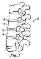
まず図1を参照して、符号10は、頸椎、胸椎、もしくは腰椎における、または脊柱の他の部位における2つの隣接する椎骨14と16との間に延在する損傷した椎間板12を有する脊柱を示す。図2を参照すると、椎間板12を除去し、2つの無傷の椎骨14と16との間に隙間を形成する典型的な外科的摘出術が行われており、本発明の一実施形態による椎間板補綴体20が上記隙間に埋入されることが理解されるであろう。 Referring initially to FIG. 1,
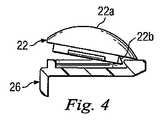
補綴体20は図3および図4に詳細に示され、図に見られるように、上端板24と下端板26との間に挿入された挿入部22を含む。上端板24は、図3および図4に見られるように湾曲した前方部または前面と、椎骨14の対応する表面に合致するように平坦または曲線状になった上面(図2)とを有する概ね方形の形状である。半球面状の凹部24aが、端板24の下面に形成され、耳部24bが端板24の前端部から上向きに延在する。 The
下端板26もまた、湾曲した前端面を有する概ね方形の形状であり、その上面は、溝26bによって2つの側部および端部を限られた概ね方形の凹部領域26aを含む。端板の外側表面から凹部領域26aまで延在する操作用切欠き部26cが、端板26の前端部に形成され、切欠き部の基部に傾斜部26dが形成される。耳部(タブ、つまみ部)26eが、端板26の前端部から下向きに延在する。端板26の下面は、図示のように平坦であるが、椎骨16(図2)の対応する表面に合致するように曲線状であってもよい。 The
端板24および26は、図2に示されるように、補綴体の後部への動きを防ぐために、椎骨14および16のそれぞれに対応する外側前面を覆って耳部24b、26eを配置することを含むであろう任意の従来の方法で、椎骨14、16にそれぞれ固定されることが理解されよう。たとえば、ねじ等のような固定具が、耳部24b、26eを含む端板24、26の任意の部分を介して椎骨14、16の中へ通され、補綴体20を椎骨に固定してよい。別の例によると、端板24の上面および端板26の下面に、骨に係合する面またはひれ状部が設けられ、椎骨14、16をそれぞれ係合して、補綴体20の堅固な埋入を強めることができる。
挿入部22は、実質的に方形の下部32と一体的に形成され、該下部32から上向きに延在するドーム(円蓋)状の上部30を有する。ドーム状の上部30は、挿入部22と端板24との間で回転動作が可能な関節接合部を形成するように、最小限の隙間を有して端板24の凹部24a内に嵌合する。 The
2つの平行な、長さ方向に延在する切欠き部32a、32bが方形部32に設けられ、該切欠き部は、方形部のそれぞれの側壁からわずかに内方向に離間される。こうして、切欠き部とその対応する側壁との間に延在する方形部32の各部が比較的に柔軟になっている。周縁の鳩尾形の突部32cが方形部32の側壁および後壁から延在し、端板26の溝26bの対応する部分の中に延在する大きさになされている。 Two parallel, longitudinally extending
耳部32dが挿入部22の前端部から外向きに延在し、適切な工具によって係合されるように構成された平坦な上面を有する。これによって、以下に説明される方法で挿入部22を下端板26に固定するのを助けるために、外科医が端板26に向かう方向に耳部32dに力を加えることができる。図4に示されるように、挿入部22は、まず、下端板26の上に、下端板の平坦面に対してわずかな角度をもって挿入部22を配置することによって、下端板26に取り付け可能である。挿入部22の方形部32の後壁から延在する突出部32cの部分が、端板26の溝26bの対応する部分の中に挿入される。 The
次に、耳部32dの上面に工具を係合して下向きに押すことによって、挿入部22の前部が端板26に対して下向きに押さえつけられる。方形部の側壁から延在する突出部32cの部分を含む、上記の比較的柔軟な方形部32の側部が、溝26bの対応する部分にかみ合う。 Next, the front portion of the
結果として、挿入部22が端板26に対して固定され、端板24と26との間に概ね包み込まれて、分離の可能性を大幅に減少させる。こうして、図5に示されるように、補綴体20が椎骨14と16との間に完全に埋め込まれ、連結された挿入部22と端板26とによって形成された組立体が、端板24に対して回転することができる。 As a result, the
挿入部22はモジュール方式およびそれと同様のものであり、異なるサイズ、構成などの別の挿入部によって、修正または交換を可能にする。このために、適切な工具(図示せず)を切欠き部26cを介して挿入し、傾斜部26dを案内として用いて、挿入部22の方形部32の下面と、端板26の上面との間にその工具を割り込ませることによって、挿入部22は下端板26から外されることができる。次に、工具が傾斜部26dを中心に旋回され、端板26から離れる方向に挿入部を押して、切り離しを行う。すると、挿入部22は、挿入部を端板26に対して前方に滑動させることによって、端板26から完全に切り離されることができる。これによって、端板24、26を椎骨14、16に固定した元の位置に維持しながら、挿入部22が交換可能になる。 The
図6は、本発明の代替的な実施形態を図示し、同じ参照符号を与えられた前述の実施形態の構造および構成要素を含む。図6の実施形態によると、耳部32dが除かれ、方形部32の平坦な端部に、上記の組立工程の際に挿入部22を端板26に向かって押さえつける工具を受けるための開口部32eが形成される。それ以外は、図6の実施形態は、図2〜図5の実施形態と同一である。 FIG. 6 illustrates an alternative embodiment of the present invention and includes the structure and components of the previous embodiment given the same reference numerals. According to the embodiment of FIG. 6, the
図7の実施形態は、図2〜図5の実施形態と同様であり、同一の構造および構成要素には同じ参照符号が与えられている。図7の実施形態によると、2つの離間された平行なレール26f、26gが、下端板26の凹部26aから上向きに突出し、それぞれ切欠き部32a、32bの中に延在するように構成されている。この状況では、図2〜図5の実施形態の切欠き部の深さと比べて、切欠き部32a、32bの深さが増加可能である。したがって、図3〜図5の実施形態に関して、上述のように挿入部22が端板26に対して固定されたとき、レール26f、26gが切欠き部32a、32bの中にそれぞれ延在し、挿入部を端板に対してさらに固定する。それ以外は、図7の実施形態は、図3〜図5の実施形態と同一であり、図7の実施形態の開口部32bが図3の実施形態の耳部32dで置き換えられることが理解される。 The embodiment of FIG. 7 is similar to the embodiment of FIGS. 2-5, and the same reference numerals are given to the same structures and components. According to the embodiment of FIG. 7, two spaced parallel rails 26f, 26g are configured to project upward from the
図8および図9の実施形態は、図2〜図5の実施形態と同様であり、同一の構造および構成要素には、同じ参照符号が与えられている。図8の実施形態によると、図2〜図5の実施形態の端板24、26のそれぞれの耳部24b、26eが除かれ、それぞれの端板の前端部に2つの突起24c、26hが設けられる。突起24c、26hは、椎骨14、16に対して補綴体20を操作する際に外科医を助けるために、対応する工具が該突起を把持することができるように、台形の断面を形成する鳩尾形である。図8の実施形態では、耳部32dが挿入部22上に示されているが、図6の開口部32dが設けられてもよいことを理解されたい。また、図7の実施形態のレール26f、26gが、図8の実施形態に設けられるか、または図8の実施形態から省かれることができる。それ以外は、図8の実施形態は、前述の実施形態と同一である。 The embodiment of FIGS. 8 and 9 is similar to the embodiment of FIGS. 2-5, and the same reference numerals are given to the same structures and components. According to the embodiment of FIG. 8, the
図9の実施形態は、図に見られるように突起24cが上向きに延在し、突起26hが下向きに延在すること以外は、図8の実施形態と同一である、したがって、突起24c、26hが、図7の実施形態に関連して上述の把持面を与えることに加えて、図2〜図5の実施形態の耳部24b、26eの機能も行う。図9の実施形態では耳部32dが挿入部22上に示されているが、図6の開口部32eが設けられてもよいことが理解されたい。また、図7の実施形態のレール26f、26gが、図9の実施形態に設けられるか、または図9の実施形態から省かれることができる。それ以外は、図9の実施形態は、前述の実施形態と同一である。 The embodiment of FIG. 9 is identical to the embodiment of FIG. 8 except that the
上述のすべての実施形態では、端板24、26は、チタン合金、コバルトクロム合金、ステンレス鋼、酸化アルミニウム、酸化ジルコニウム、多結晶ダイアモンド、熱分解カーボンを含む任意の適切な生体適合性の材料から形成されてよく、挿入部22は、超高分子量ポリエチレン(UHMWPE)、ポリエーテルエーテルケトン(UHMWPEと架橋されたPEEK)、または他の適切な材料から形成されることができる。端板24、26、および/または挿入部22の表面は、補綴体20の増力または内部への成長の特性を高める特徴または被覆を含む。たとえば、ヒドロキシアパタイト(HA)などの血漿または生体に適合性のある、骨誘導性の材料が、1つまたは複数の上記表面の全体または一部を被覆してよい。他の適切な被覆または処理は、多孔質ビーズ被覆、多孔質メッシュ被覆、骨形成ペプチド被覆、成長因子被覆、rh−BMF被覆、および/またはグリットブラストを含んでよい。挿入部22のドーム部30および上端板24の凹部24aのそれぞれの表面は、それらの関節の動きの結果として許容可能な摩耗特性を与えるのに十分な耐久性があるように選択または処理されてよい。 In all the embodiments described above, the
(変更例)
本発明から逸脱することなく、上記の内容に変更が行われてよいことが理解されるであろうが、いくつかの変更例は以下の通りである。(Example of change)
It will be understood that changes may be made to the above without departing from the invention, but a few examples are as follows.
(1)補綴体20は、椎骨以外の体の部分の間に埋入されてよい。 (1) The
(2)補綴体20は、少なくとも1つの椎骨が除去される切除術の後に、2つの椎骨の間に挿入されてよい。 (2) The
(3)挿入部22は、補綴体が埋入される特定の部位、およびさらに具体的には、端板24、26が椎骨14、16にそれぞれ連結された後の端板24と26との間の空間によって、形状、サイズ、構成、および物理的特性がいくらか異なってよい。 (3) The
(4)挿入部22の上ドーム部は、異なる形状の突起部によって置き換えられてもよい。 (4) The upper dome portion of the
(5)ドームは、端板24の下面に形成されてよく、対応する凹部は、挿入部22の上面に形成されてよい。 (5) The dome may be formed on the lower surface of the
(6)補綴体20は、椎骨14と16との間に、図2に示される位置とは反転した位置に埋入されてよい。端板26が上椎骨14に連結され、端板24が椎骨16に連結される場合、端板24および26の一方または両方が、形状が異なってよい。 (6) The
(7)図7の実施形態では、レール26f、26gを端板26に、対応する切欠き部32c、32dを挿入部22に設ける代わりに、レールが挿入部に、切欠き部が端板に設けられることができる。 (7) In the embodiment of FIG. 7, instead of providing the rails 26f and 26g on the
(8)突起(24cまたは26h)が、端板24、26の一方に設けられ、他方に設けられなくてよい。 (8) The protrusion (24c or 26h) is provided on one of the
(9)図2〜図5の実施形態の開口部32dを省いてもよい。 (9) You may omit the
(10)「下に」「上に」「間に」「上」「下」などのような上記の空間的な関係は、例示の目的のためのみであり、上記の構造の特定の向きまたは位置を限定するものではない。 (10) The above spatial relationships such as “below”, “above”, “between”, “upper”, “below”, etc. are for illustrative purposes only, and are specific orientations of the above structure or The position is not limited.
前述の特定の実施形態は、本発明の実施の例である。したがって、当業者に既知である、または本明細書に開示された他の方便が、上記のように、本発明または添付の特許請求の範囲から逸脱することなく使用可能であることを理解されたい。特許請求の範囲においては、ミーンズプラスファンクション節が、引用された機能を行うように本明細書に述べられる構造に及び、また、構造的均等物だけでなく、均等な構造物にも及ぶことが意図されている。したがって、釘が木製部品を合わせて固定するために円筒形の表面を用い、一方ねじが螺旋状の表面を用いる点において、釘とねじとは構造的均等物ではないであろうが、木製部品を固定する環境においては、釘とねじとは均等な構造物である。 The specific embodiments described above are examples of implementations of the invention. Accordingly, it should be understood that other flights known to those skilled in the art or disclosed herein may be used as described above without departing from the present invention or the appended claims. . In the claims, the means plus function section may extend to the structures described herein to perform the recited function, and may extend not only to structural equivalents, but also to equivalent structures. Is intended. Thus, the nail and screw would not be a structural equivalent in that the nail uses a cylindrical surface to secure the wooden parts together, while the screw uses a helical surface, but the wooden parts In an environment in which the nail is fixed, the nail and the screw are equal structures.
Claims (31)
Translated fromJapanese溝を有し、第2椎骨を係合するための第2端板と、
前記第1端板と挿入部との間で相対的な動作を可能にするやり方で、前記第1端板を係合する挿入部であって、突出部を有し、当該突出部は、前記挿入部を前記第2端板と固定的に係合するように構成され、また、前記突出部は、前記挿入部を前記第2端板から切り離し可能にするために前記溝から手動で取り外されるように、前記溝の中に延在すべく構成される、挿入部と、を備える椎間インプラント。A first end plate for engaging the first vertebra;
A second end plate having a groove and for engaging the second vertebra;
An insertion portion for engaging the first end plate in a manner that allows relative movement between the first end plate and the insertion portion, the protrusion having a protrusion, the protrusion being the An insert is configured to securely engage the second end plate, and the protrusion is manually removed from the groove to allow the insert to be disconnected from the second end plate. An intervertebral implant comprising an insertion portion configured to extend into the groove.
第2椎骨を第2端板に係合する工程と、
前記第1端板と挿入部との間で相対的な動作を可能にするやり方で、第1端板を挿入部に係合する工程と、
前記挿入部を前記第2端に固定するために、前記挿入部の突出部を前記第2端板の溝と係合する工程と、を含む椎間補綴体を埋入する方法。Engaging the first vertebra with the first endplate;
Engaging the second vertebra with the second endplate;
Engaging the first end plate with the insert in a manner that allows relative movement between the first end plate and the insert;
A method of implanting an intervertebral prosthesis comprising: engaging a protrusion of the insert with a groove in the second end plate to secure the insert to the second end.
体の第2部分を係合するための第2端板と、
前記第1端板と手段との間で相対的な動作を可能にするやり方で、前記第1端板を係合し、前記第2端板に切り離し可能に固定する手段と、を備えるインプラント。A first end plate for engaging a first part of the body;
A second end plate for engaging the second part of the body;
Means for engaging the first end plate and releasably securing it to the second end plate in a manner that allows relative movement between the first end plate and the means.
第2端板を体の第2部分に取り付ける工程と、
前記第1端板と挿入部との間で相対的な動作を可能にするやり方で、前記第1端板を挿入部に係合する工程と、
前記挿入部を前記第2端板に取り外し可能に固定する工程と、を含む補綴体を埋入する方法。Attaching the first end plate to the first part of the body;
Attaching the second end plate to the second part of the body;
Engaging the first end plate with the insertion portion in a manner that allows relative movement between the first end plate and the insertion portion;
Fixing the insertion portion to the second end plate in a removable manner.
Applications Claiming Priority (2)
| Application Number | Priority Date | Filing Date | Title |
|---|---|---|---|
| US11/010,171US20060149371A1 (en) | 2004-12-10 | 2004-12-10 | Intervertebral prosthetic device and method with locking mechanism |
| PCT/US2005/045239WO2006063363A1 (en) | 2004-12-10 | 2005-12-12 | Intervertebral prosthetic device and method with locking mechanism |
Publications (1)
| Publication Number | Publication Date |
|---|---|
| JP2008522768Atrue JP2008522768A (en) | 2008-07-03 |
Family
ID=36081313
Family Applications (1)
| Application Number | Title | Priority Date | Filing Date |
|---|---|---|---|
| JP2007545731APendingJP2008522768A (en) | 2004-12-10 | 2005-12-12 | Device for intervertebral prosthesis with fixation mechanism |
Country Status (7)
| Country | Link |
|---|---|
| US (1) | US20060149371A1 (en) |
| EP (1) | EP1835869A1 (en) |
| JP (1) | JP2008522768A (en) |
| CN (1) | CN101083959A (en) |
| AU (1) | AU2005314439A1 (en) |
| CA (1) | CA2590154A1 (en) |
| WO (1) | WO2006063363A1 (en) |
Families Citing this family (31)
| Publication number | Priority date | Publication date | Assignee | Title |
|---|---|---|---|---|
| FR2824261B1 (en) | 2001-05-04 | 2004-05-28 | Ldr Medical | INTERVERTEBRAL DISC PROSTHESIS AND IMPLEMENTATION METHOD AND TOOLS |
| FR2846550B1 (en) | 2002-11-05 | 2006-01-13 | Ldr Medical | INTERVERTEBRAL DISC PROSTHESIS |
| EP2113227B1 (en) | 2004-02-04 | 2015-07-29 | LDR Medical | Intervertebral disc prosthesis |
| FR2865629B1 (en) | 2004-02-04 | 2007-01-26 | Ldr Medical | INTERVERTEBRAL DISC PROSTHESIS |
| FR2869528B1 (en)* | 2004-04-28 | 2007-02-02 | Ldr Medical | INTERVERTEBRAL DISC PROSTHESIS |
| FR2879436B1 (en) | 2004-12-22 | 2007-03-09 | Ldr Medical | INTERVERTEBRAL DISC PROSTHESIS |
| FR2887762B1 (en) | 2005-06-29 | 2007-10-12 | Ldr Medical Soc Par Actions Si | INTERVERTEBRAL DISC PROSTHESIS INSERTION INSTRUMENTATION BETWEEN VERTEBRATES |
| FR2891135B1 (en) | 2005-09-23 | 2008-09-12 | Ldr Medical Sarl | INTERVERTEBRAL DISC PROSTHESIS |
| FR2893838B1 (en) | 2005-11-30 | 2008-08-08 | Ldr Medical Soc Par Actions Si | PROSTHESIS OF INTERVERTEBRAL DISC AND INSTRUMENTATION OF INSERTION OF THE PROSTHESIS BETWEEN VERTEBRATES |
| US7867279B2 (en)* | 2006-01-23 | 2011-01-11 | Depuy Spine, Inc. | Intervertebral disc prosthesis |
| FR2903157B1 (en) | 2006-06-29 | 2009-10-30 | Bioprofile Sa | ASSEMBLY OF A PIECE OF PYROCARBON AND ANOTHER PIECE |
| WO2008088777A2 (en)* | 2007-01-12 | 2008-07-24 | Synthes Usa, Llc | Modular intervertebral implant |
| US8465546B2 (en) | 2007-02-16 | 2013-06-18 | Ldr Medical | Intervertebral disc prosthesis insertion assemblies |
| FR2916956B1 (en) | 2007-06-08 | 2012-12-14 | Ldr Medical | INTERSOMATIC CAGE, INTERVERTEBRAL PROSTHESIS, ANCHORING DEVICE AND IMPLANTATION INSTRUMENTATION |
| US8852280B2 (en)* | 2007-09-27 | 2014-10-07 | Warsaw Orthopedic, Inc. | Intervertebral implant |
| US20090112325A1 (en)* | 2007-10-30 | 2009-04-30 | Biospine, Llc | Footplate member and a method for use in a vertebral body replacement device |
| US8142441B2 (en)* | 2008-10-16 | 2012-03-27 | Aesculap Implant Systems, Llc | Surgical instrument and method of use for inserting an implant between two bones |
| US8182537B2 (en)* | 2007-10-30 | 2012-05-22 | Aesculap Implant Systems, Llc | Vertebral body replacement device and method for use to maintain a space between two vertebral bodies within a spine |
| US8591587B2 (en) | 2007-10-30 | 2013-11-26 | Aesculap Implant Systems, Llc | Vertebral body replacement device and method for use to maintain a space between two vertebral bodies within a spine |
| US9216085B2 (en)* | 2008-02-28 | 2015-12-22 | Biopoly, Llc | Partial joint resurfacing implant, instrumentation, and method |
| CN101242696B (en)* | 2008-03-18 | 2011-08-24 | 清华大学 | Adaptive automotive headlight control |
| US8142435B2 (en) | 2009-02-19 | 2012-03-27 | Aesculap Implant Systems, Llc | Multi-functional surgical instrument and method of use for inserting an implant between two bones |
| US20100241231A1 (en)* | 2009-02-20 | 2010-09-23 | Marino James F | Intervertebral fixation device |
| US20110035010A1 (en)* | 2009-08-07 | 2011-02-10 | Ebi, Llc | Toroid-shaped spinal disc |
| US9173748B2 (en)* | 2009-08-07 | 2015-11-03 | Ebi, Llc | Toroid-shaped spinal disc |
| US8353964B2 (en) | 2010-11-04 | 2013-01-15 | Carpenter Clyde T | Anatomic total disc replacement |
| CN102048601B (en)* | 2010-12-29 | 2013-04-17 | 哈尔滨医科大学 | Piston type titanium wire mesh cage and manufacturing method thereof |
| US8628578B2 (en)* | 2011-12-19 | 2014-01-14 | Warsaw Orthopedic, Inc. | Expandable interbody implant and methods of use |
| CN103479451A (en)* | 2013-10-10 | 2014-01-01 | 北京贝思达生物技术有限公司 | Polyether-ether-ketone artificial spine intervertebral disc |
| US11197765B2 (en) | 2019-12-04 | 2021-12-14 | Robert S. Bray, Jr. | Artificial disc replacement device |
| US11839554B2 (en) | 2020-01-23 | 2023-12-12 | Robert S. Bray, Jr. | Method of implanting an artificial disc replacement device |
Family Cites Families (27)
| Publication number | Priority date | Publication date | Assignee | Title |
|---|---|---|---|---|
| DE3809793A1 (en)* | 1988-03-23 | 1989-10-05 | Link Waldemar Gmbh Co | SURGICAL INSTRUMENT SET |
| FR2659226B1 (en)* | 1990-03-07 | 1992-05-29 | Jbs Sa | PROSTHESIS FOR INTERVERTEBRAL DISCS AND ITS IMPLEMENTATION INSTRUMENTS. |
| GB9125798D0 (en)* | 1991-12-04 | 1992-02-05 | Customflex Limited | Improvements in or relating to spinal vertebrae implants |
| US5425773A (en)* | 1992-01-06 | 1995-06-20 | Danek Medical, Inc. | Intervertebral disk arthroplasty device |
| DE4208116C2 (en)* | 1992-03-13 | 1995-08-03 | Link Waldemar Gmbh Co | Intervertebral disc prosthesis |
| EP0566810B1 (en)* | 1992-04-21 | 1996-08-14 | SULZER Medizinaltechnik AG | Artificial spinal disc |
| FR2718635B1 (en)* | 1994-04-15 | 1996-07-05 | Axcyl Medical | Cervical prosthesis. |
| US5620443A (en)* | 1995-01-25 | 1997-04-15 | Danek Medical, Inc. | Anterior screw-rod connector |
| US5810818A (en)* | 1995-10-23 | 1998-09-22 | Fastenetix, Llc | Spinal hook implant having a low blade and S swivel hook |
| US5836948A (en)* | 1997-01-02 | 1998-11-17 | Saint Francis Medical Technologies, Llc | Spine distraction implant and method |
| US6146421A (en)* | 1997-08-04 | 2000-11-14 | Gordon, Maya, Roberts And Thomas, Number 1, Llc | Multiple axis intervertebral prosthesis |
| US6682561B2 (en)* | 1998-06-18 | 2004-01-27 | Pioneer Laboratories, Inc. | Spinal fixation system |
| US6368350B1 (en)* | 1999-03-11 | 2002-04-09 | Sulzer Spine-Tech Inc. | Intervertebral disc prosthesis and method |
| US6936071B1 (en)* | 1999-07-02 | 2005-08-30 | Spine Solutions, Inc. | Intervertebral implant |
| US6468311B2 (en)* | 2001-01-22 | 2002-10-22 | Sdgi Holdings, Inc. | Modular interbody fusion implant |
| US6989032B2 (en)* | 2001-07-16 | 2006-01-24 | Spinecore, Inc. | Artificial intervertebral disc |
| US6740118B2 (en)* | 2002-01-09 | 2004-05-25 | Sdgi Holdings, Inc. | Intervertebral prosthetic joint |
| EP1482877B1 (en)* | 2002-03-11 | 2007-05-30 | Spinal Concepts Inc. | Instrumentation for implanting spinal implant devices |
| EP1344507A1 (en)* | 2002-03-12 | 2003-09-17 | Waldemar Link (GmbH & Co.) | Intervertebral prosthesis for the cervical spine |
| RU2303422C2 (en)* | 2002-03-12 | 2007-07-27 | Сервитек Инк. | Intervertebral prosthesis and system of intervertebral prostheses, in peculiar case, for cervical department of vertebral column |
| US6726720B2 (en)* | 2002-03-27 | 2004-04-27 | Depuy Spine, Inc. | Modular disc prosthesis |
| US6793678B2 (en)* | 2002-06-27 | 2004-09-21 | Depuy Acromed, Inc. | Prosthetic intervertebral motion disc having dampening |
| US6899735B2 (en)* | 2002-10-02 | 2005-05-31 | Sdgi Holdings, Inc. | Modular intervertebral prosthesis system |
| US7153325B2 (en)* | 2003-08-01 | 2006-12-26 | Ultra-Kinetics, Inc. | Prosthetic intervertebral disc and methods for using the same |
| DE50307429D1 (en)* | 2003-08-04 | 2007-07-19 | Cervitech Inc | Cervical prosthesis with insertion instrument |
| FR2862866B1 (en)* | 2003-11-28 | 2006-12-15 | Gilles Voydeville | POSTERO-LATERAL INTERVERTEBRAL DISCSTRATE |
| DE202004009542U1 (en)* | 2004-06-16 | 2004-08-12 | Aesculap Ag & Co. Kg | Artificial intervertebral disk, comprising core with intensely curved upper and less curved lower surface |
- 2004
- 2004-12-10USUS11/010,171patent/US20060149371A1/ennot_activeAbandoned
- 2005
- 2005-12-12CACA002590154Apatent/CA2590154A1/ennot_activeAbandoned
- 2005-12-12WOPCT/US2005/045239patent/WO2006063363A1/enactiveApplication Filing
- 2005-12-12AUAU2005314439Apatent/AU2005314439A1/ennot_activeAbandoned
- 2005-12-12CNCNA2005800421438Apatent/CN101083959A/enactivePending
- 2005-12-12EPEP05854037Apatent/EP1835869A1/ennot_activeWithdrawn
- 2005-12-12JPJP2007545731Apatent/JP2008522768A/enactivePending
Also Published As
| Publication number | Publication date |
|---|---|
| CN101083959A (en) | 2007-12-05 |
| WO2006063363A1 (en) | 2006-06-15 |
| US20060149371A1 (en) | 2006-07-06 |
| CA2590154A1 (en) | 2006-06-15 |
| EP1835869A1 (en) | 2007-09-26 |
| AU2005314439A1 (en) | 2006-06-15 |
Similar Documents
| Publication | Publication Date | Title |
|---|---|---|
| JP2008522768A (en) | Device for intervertebral prosthesis with fixation mechanism | |
| US20190105171A1 (en) | Intervertebral disc | |
| US8888852B2 (en) | Spinal athroplasty device and method | |
| JP5876465B2 (en) | Interosseous device | |
| US8480746B2 (en) | Transforaminal prosthetic spinal disc replacement | |
| US20070162138A1 (en) | Vertebral implant and insertion tool | |
| US20040133278A1 (en) | Spinal disc implant | |
| US8092534B2 (en) | Revision device | |
| WO2000042944A1 (en) | Multiple axis intervertebral prosthesis | |
| AU2005206133B2 (en) | Spinal arthroplasty device and method |