JP2008522751A - Automatic injection and retraction syringe - Google Patents
Automatic injection and retraction syringeDownload PDFInfo
- Publication number
- JP2008522751A JP2008522751AJP2007545617AJP2007545617AJP2008522751AJP 2008522751 AJP2008522751 AJP 2008522751AJP 2007545617 AJP2007545617 AJP 2007545617AJP 2007545617 AJP2007545617 AJP 2007545617AJP 2008522751 AJP2008522751 AJP 2008522751A
- Authority
- JP
- Japan
- Prior art keywords
- assembly
- retraction
- injection
- spring
- infusion
- Prior art date
- Legal status (The legal status is an assumption and is not a legal conclusion. Google has not performed a legal analysis and makes no representation as to the accuracy of the status listed.)
- Granted
Links
- 238000002347injectionMethods0.000titleclaimsabstractdescription154
- 239000007924injectionSubstances0.000titleclaimsabstractdescription154
- 238000001802infusionMethods0.000claimsabstractdescription69
- 239000003814drugSubstances0.000claimsabstractdescription53
- 229940079593drugDrugs0.000claimsabstractdescription47
- 238000007789sealingMethods0.000claimsabstractdescription19
- 230000008878couplingEffects0.000claimsdescription27
- 238000010168coupling processMethods0.000claimsdescription27
- 238000005859coupling reactionMethods0.000claimsdescription27
- 239000002184metalSubstances0.000claimsdescription9
- 238000004140cleaningMethods0.000claimsdescription5
- 239000007858starting materialSubstances0.000claimsdescription4
- 239000000853adhesiveSubstances0.000claimsdescription3
- 230000001070adhesive effectEffects0.000claimsdescription3
- 239000002991molded plasticSubstances0.000claimsdescription3
- 239000013536elastomeric materialSubstances0.000claimsdescription2
- 230000000712assemblyEffects0.000abstractdescription2
- 238000000429assemblyMethods0.000abstractdescription2
- 239000002131composite materialSubstances0.000description8
- 238000004519manufacturing processMethods0.000description5
- 239000012530fluidSubstances0.000description4
- 230000036541healthEffects0.000description4
- 230000009471actionEffects0.000description3
- 238000009434installationMethods0.000description3
- 230000007246mechanismEffects0.000description3
- 239000004033plasticSubstances0.000description3
- 238000003825pressingMethods0.000description3
- LFQSCWFLJHTTHZ-UHFFFAOYSA-NEthanolChemical compoundCCOLFQSCWFLJHTTHZ-UHFFFAOYSA-N0.000description2
- 206010069803Injury associated with deviceDiseases0.000description2
- 238000004891communicationMethods0.000description2
- 230000000994depressogenic effectEffects0.000description2
- 201000010099diseaseDiseases0.000description2
- 208000037265diseases, disorders, signs and symptomsDiseases0.000description2
- 238000010255intramuscular injectionMethods0.000description2
- 239000007927intramuscular injectionSubstances0.000description2
- 239000000463materialSubstances0.000description2
- 238000012986modificationMethods0.000description2
- 230000004048modificationEffects0.000description2
- 208000030507AIDSDiseases0.000description1
- 206010002199Anaphylactic shockDiseases0.000description1
- 241000371980Influenza B virus (B/Shanghai/361/2002)Species0.000description1
- 230000002009allergenic effectEffects0.000description1
- 208000003455anaphylaxisDiseases0.000description1
- 229940090047auto-injectorDrugs0.000description1
- 230000002146bilateral effectEffects0.000description1
- 230000008859changeEffects0.000description1
- 239000013013elastic materialSubstances0.000description1
- 208000006454hepatitisDiseases0.000description1
- 231100000283hepatitisToxicity0.000description1
- 230000000977initiatory effectEffects0.000description1
- 238000000034methodMethods0.000description1
- 239000003607modifierSubstances0.000description1
- 230000008569processEffects0.000description1
- 230000001681protective effectEffects0.000description1
- 238000004080punchingMethods0.000description1
- 230000000452restraining effectEffects0.000description1
- 239000000243solutionSubstances0.000description1
- 238000010254subcutaneous injectionMethods0.000description1
- 239000007929subcutaneous injectionSubstances0.000description1
- 239000000126substanceSubstances0.000description1
- 238000013519translationMethods0.000description1
- 230000003313weakening effectEffects0.000description1
Images


Classifications
- A—HUMAN NECESSITIES
- A61—MEDICAL OR VETERINARY SCIENCE; HYGIENE
- A61M—DEVICES FOR INTRODUCING MEDIA INTO, OR ONTO, THE BODY; DEVICES FOR TRANSDUCING BODY MEDIA OR FOR TAKING MEDIA FROM THE BODY; DEVICES FOR PRODUCING OR ENDING SLEEP OR STUPOR
- A61M5/00—Devices for bringing media into the body in a subcutaneous, intra-vascular or intramuscular way; Accessories therefor, e.g. filling or cleaning devices, arm-rests
- A61M5/178—Syringes
- A61M5/1782—Devices aiding filling of syringes in situ
- A—HUMAN NECESSITIES
- A61—MEDICAL OR VETERINARY SCIENCE; HYGIENE
- A61M—DEVICES FOR INTRODUCING MEDIA INTO, OR ONTO, THE BODY; DEVICES FOR TRANSDUCING BODY MEDIA OR FOR TAKING MEDIA FROM THE BODY; DEVICES FOR PRODUCING OR ENDING SLEEP OR STUPOR
- A61M5/00—Devices for bringing media into the body in a subcutaneous, intra-vascular or intramuscular way; Accessories therefor, e.g. filling or cleaning devices, arm-rests
- A61M5/001—Apparatus specially adapted for cleaning or sterilising syringes or needles
- A—HUMAN NECESSITIES
- A61—MEDICAL OR VETERINARY SCIENCE; HYGIENE
- A61M—DEVICES FOR INTRODUCING MEDIA INTO, OR ONTO, THE BODY; DEVICES FOR TRANSDUCING BODY MEDIA OR FOR TAKING MEDIA FROM THE BODY; DEVICES FOR PRODUCING OR ENDING SLEEP OR STUPOR
- A61M5/00—Devices for bringing media into the body in a subcutaneous, intra-vascular or intramuscular way; Accessories therefor, e.g. filling or cleaning devices, arm-rests
- A61M5/178—Syringes
- A61M5/20—Automatic syringes, e.g. with automatically actuated piston rod, with automatic needle injection, filling automatically
- A61M5/2033—Spring-loaded one-shot injectors with or without automatic needle insertion
- A—HUMAN NECESSITIES
- A61—MEDICAL OR VETERINARY SCIENCE; HYGIENE
- A61M—DEVICES FOR INTRODUCING MEDIA INTO, OR ONTO, THE BODY; DEVICES FOR TRANSDUCING BODY MEDIA OR FOR TAKING MEDIA FROM THE BODY; DEVICES FOR PRODUCING OR ENDING SLEEP OR STUPOR
- A61M5/00—Devices for bringing media into the body in a subcutaneous, intra-vascular or intramuscular way; Accessories therefor, e.g. filling or cleaning devices, arm-rests
- A61M5/178—Syringes
- A61M5/24—Ampoule syringes, i.e. syringes with needle for use in combination with replaceable ampoules or carpules, e.g. automatic
- A61M5/2455—Ampoule syringes, i.e. syringes with needle for use in combination with replaceable ampoules or carpules, e.g. automatic with sealing means to be broken or opened
- A61M5/2459—Ampoule syringes, i.e. syringes with needle for use in combination with replaceable ampoules or carpules, e.g. automatic with sealing means to be broken or opened upon internal pressure increase, e.g. pierced or burst
- A—HUMAN NECESSITIES
- A61—MEDICAL OR VETERINARY SCIENCE; HYGIENE
- A61M—DEVICES FOR INTRODUCING MEDIA INTO, OR ONTO, THE BODY; DEVICES FOR TRANSDUCING BODY MEDIA OR FOR TAKING MEDIA FROM THE BODY; DEVICES FOR PRODUCING OR ENDING SLEEP OR STUPOR
- A61M5/00—Devices for bringing media into the body in a subcutaneous, intra-vascular or intramuscular way; Accessories therefor, e.g. filling or cleaning devices, arm-rests
- A61M5/178—Syringes
- A61M5/28—Syringe ampoules or carpules, i.e. ampoules or carpules provided with a needle
- A61M5/285—Syringe ampoules or carpules, i.e. ampoules or carpules provided with a needle with sealing means to be broken or opened
- A61M5/286—Syringe ampoules or carpules, i.e. ampoules or carpules provided with a needle with sealing means to be broken or opened upon internal pressure increase, e.g. pierced or burst
- A—HUMAN NECESSITIES
- A61—MEDICAL OR VETERINARY SCIENCE; HYGIENE
- A61M—DEVICES FOR INTRODUCING MEDIA INTO, OR ONTO, THE BODY; DEVICES FOR TRANSDUCING BODY MEDIA OR FOR TAKING MEDIA FROM THE BODY; DEVICES FOR PRODUCING OR ENDING SLEEP OR STUPOR
- A61M5/00—Devices for bringing media into the body in a subcutaneous, intra-vascular or intramuscular way; Accessories therefor, e.g. filling or cleaning devices, arm-rests
- A61M5/178—Syringes
- A61M5/31—Details
- A61M5/315—Pistons; Piston-rods; Guiding, blocking or restricting the movement of the rod or piston; Appliances on the rod for facilitating dosing ; Dosing mechanisms
- A61M5/31596—Pistons; Piston-rods; Guiding, blocking or restricting the movement of the rod or piston; Appliances on the rod for facilitating dosing ; Dosing mechanisms comprising means for injection of two or more media, e.g. by mixing
- A—HUMAN NECESSITIES
- A61—MEDICAL OR VETERINARY SCIENCE; HYGIENE
- A61M—DEVICES FOR INTRODUCING MEDIA INTO, OR ONTO, THE BODY; DEVICES FOR TRANSDUCING BODY MEDIA OR FOR TAKING MEDIA FROM THE BODY; DEVICES FOR PRODUCING OR ENDING SLEEP OR STUPOR
- A61M5/00—Devices for bringing media into the body in a subcutaneous, intra-vascular or intramuscular way; Accessories therefor, e.g. filling or cleaning devices, arm-rests
- A61M5/178—Syringes
- A61M5/31—Details
- A61M5/32—Needles; Details of needles pertaining to their connection with syringe or hub; Accessories for bringing the needle into, or holding the needle on, the body; Devices for protection of needles
- A61M5/3202—Devices for protection of the needle before use, e.g. caps
- A—HUMAN NECESSITIES
- A61—MEDICAL OR VETERINARY SCIENCE; HYGIENE
- A61M—DEVICES FOR INTRODUCING MEDIA INTO, OR ONTO, THE BODY; DEVICES FOR TRANSDUCING BODY MEDIA OR FOR TAKING MEDIA FROM THE BODY; DEVICES FOR PRODUCING OR ENDING SLEEP OR STUPOR
- A61M5/00—Devices for bringing media into the body in a subcutaneous, intra-vascular or intramuscular way; Accessories therefor, e.g. filling or cleaning devices, arm-rests
- A61M5/178—Syringes
- A61M5/31—Details
- A61M5/32—Needles; Details of needles pertaining to their connection with syringe or hub; Accessories for bringing the needle into, or holding the needle on, the body; Devices for protection of needles
- A61M5/3205—Apparatus for removing or disposing of used needles or syringes, e.g. containers; Means for protection against accidental injuries from used needles
- A61M5/321—Means for protection against accidental injuries by used needles
- A61M5/3243—Means for protection against accidental injuries by used needles being axially-extensible, e.g. protective sleeves coaxially slidable on the syringe barrel
- A61M5/326—Fully automatic sleeve extension, i.e. in which triggering of the sleeve does not require a deliberate action by the user
- A—HUMAN NECESSITIES
- A61—MEDICAL OR VETERINARY SCIENCE; HYGIENE
- A61M—DEVICES FOR INTRODUCING MEDIA INTO, OR ONTO, THE BODY; DEVICES FOR TRANSDUCING BODY MEDIA OR FOR TAKING MEDIA FROM THE BODY; DEVICES FOR PRODUCING OR ENDING SLEEP OR STUPOR
- A61M5/00—Devices for bringing media into the body in a subcutaneous, intra-vascular or intramuscular way; Accessories therefor, e.g. filling or cleaning devices, arm-rests
- A61M5/178—Syringes
- A61M5/20—Automatic syringes, e.g. with automatically actuated piston rod, with automatic needle injection, filling automatically
- A61M2005/206—With automatic needle insertion
- A—HUMAN NECESSITIES
- A61—MEDICAL OR VETERINARY SCIENCE; HYGIENE
- A61M—DEVICES FOR INTRODUCING MEDIA INTO, OR ONTO, THE BODY; DEVICES FOR TRANSDUCING BODY MEDIA OR FOR TAKING MEDIA FROM THE BODY; DEVICES FOR PRODUCING OR ENDING SLEEP OR STUPOR
- A61M5/00—Devices for bringing media into the body in a subcutaneous, intra-vascular or intramuscular way; Accessories therefor, e.g. filling or cleaning devices, arm-rests
- A61M5/178—Syringes
- A61M5/20—Automatic syringes, e.g. with automatically actuated piston rod, with automatic needle injection, filling automatically
- A61M2005/2073—Automatic syringes, e.g. with automatically actuated piston rod, with automatic needle injection, filling automatically preventing premature release, e.g. by making use of a safety lock
- A—HUMAN NECESSITIES
- A61—MEDICAL OR VETERINARY SCIENCE; HYGIENE
- A61M—DEVICES FOR INTRODUCING MEDIA INTO, OR ONTO, THE BODY; DEVICES FOR TRANSDUCING BODY MEDIA OR FOR TAKING MEDIA FROM THE BODY; DEVICES FOR PRODUCING OR ENDING SLEEP OR STUPOR
- A61M5/00—Devices for bringing media into the body in a subcutaneous, intra-vascular or intramuscular way; Accessories therefor, e.g. filling or cleaning devices, arm-rests
- A61M5/178—Syringes
- A61M5/24—Ampoule syringes, i.e. syringes with needle for use in combination with replaceable ampoules or carpules, e.g. automatic
- A61M2005/2403—Ampoule inserted into the ampoule holder
- A—HUMAN NECESSITIES
- A61—MEDICAL OR VETERINARY SCIENCE; HYGIENE
- A61M—DEVICES FOR INTRODUCING MEDIA INTO, OR ONTO, THE BODY; DEVICES FOR TRANSDUCING BODY MEDIA OR FOR TAKING MEDIA FROM THE BODY; DEVICES FOR PRODUCING OR ENDING SLEEP OR STUPOR
- A61M5/00—Devices for bringing media into the body in a subcutaneous, intra-vascular or intramuscular way; Accessories therefor, e.g. filling or cleaning devices, arm-rests
- A61M5/178—Syringes
- A61M5/31—Details
- A61M2005/3103—Leak prevention means for distal end of syringes, i.e. syringe end for mounting a needle
- A61M2005/3107—Leak prevention means for distal end of syringes, i.e. syringe end for mounting a needle for needles
- A—HUMAN NECESSITIES
- A61—MEDICAL OR VETERINARY SCIENCE; HYGIENE
- A61M—DEVICES FOR INTRODUCING MEDIA INTO, OR ONTO, THE BODY; DEVICES FOR TRANSDUCING BODY MEDIA OR FOR TAKING MEDIA FROM THE BODY; DEVICES FOR PRODUCING OR ENDING SLEEP OR STUPOR
- A61M5/00—Devices for bringing media into the body in a subcutaneous, intra-vascular or intramuscular way; Accessories therefor, e.g. filling or cleaning devices, arm-rests
- A61M5/178—Syringes
- A61M5/31—Details
- A61M5/315—Pistons; Piston-rods; Guiding, blocking or restricting the movement of the rod or piston; Appliances on the rod for facilitating dosing ; Dosing mechanisms
- A61M5/31511—Piston or piston-rod constructions, e.g. connection of piston with piston-rod
- A61M2005/31516—Piston or piston-rod constructions, e.g. connection of piston with piston-rod reducing dead-space in the syringe barrel after delivery
- A—HUMAN NECESSITIES
- A61—MEDICAL OR VETERINARY SCIENCE; HYGIENE
- A61M—DEVICES FOR INTRODUCING MEDIA INTO, OR ONTO, THE BODY; DEVICES FOR TRANSDUCING BODY MEDIA OR FOR TAKING MEDIA FROM THE BODY; DEVICES FOR PRODUCING OR ENDING SLEEP OR STUPOR
- A61M5/00—Devices for bringing media into the body in a subcutaneous, intra-vascular or intramuscular way; Accessories therefor, e.g. filling or cleaning devices, arm-rests
- A61M5/178—Syringes
- A61M5/31—Details
- A61M5/3129—Syringe barrels
Landscapes
- Health & Medical Sciences (AREA)
- Engineering & Computer Science (AREA)
- Hematology (AREA)
- Anesthesiology (AREA)
- Biomedical Technology (AREA)
- Heart & Thoracic Surgery (AREA)
- Vascular Medicine (AREA)
- Life Sciences & Earth Sciences (AREA)
- Animal Behavior & Ethology (AREA)
- General Health & Medical Sciences (AREA)
- Public Health (AREA)
- Veterinary Medicine (AREA)
- Environmental & Geological Engineering (AREA)
- Infusion, Injection, And Reservoir Apparatuses (AREA)
- Fuel-Injection Apparatus (AREA)
Abstract
Translated fromJapaneseDescription
Translated fromJapanese 関連出願との相互参照
本出願は、2004年12月9日出願の米国仮特許出願番号60/634,486の優先権を主張する。又、本出願は、本出願と共通に所有され又帰属される2003年6月20日出願の米国特許出願番号10/601,212に関連するものである。これら両方の内容は引用をもって本出願に組み込まれる。This application claims priority to US Provisional Patent Application No. 60 / 634,486, filed Dec. 9, 2004. This application is also related to US patent application Ser. No. 10 / 601,212 filed Jun. 20, 2003, commonly owned and assigned to this application. The contents of both of these are incorporated herein by reference.
発明の背景
1.発明の分野
本開示は、自動注入及び引き込みシリンジ(注射器)に関するものである。より詳しくは、本開示は、互いに選択的に接続可能な引き込みアセンブリと注入アセンブリとを有する自動注入及び引き込みシリンジに関するものである。BACKGROUND OF THE INVENTION FIELD OF THE DISCLOSURE The present disclosure relates to automatic injection and retraction syringes. More particularly, the present disclosure relates to an automatic injection and retraction syringe having a retraction assembly and an injection assembly that are selectively connectable to each other.
2.関連技術の説明
エイズ、肝炎などの病気が一般の人たちの間で増加している。これらの病気の出現は、シリンジアセンブリの使用中における不慮の針刺しを防止することに対する要望を増大させた。多くの従来の装置は、不慮の針刺しを軽減するために自己引き込み針を有する。2. Description of Related Art Diseases such as AIDS and hepatitis are increasing among the general public. The emergence of these diseases has increased the desire to prevent accidental needle sticks during use of the syringe assembly. Many conventional devices have self-retracting needles to reduce accidental needle sticks.
アレルギー誘発アナフィラキシーショック、並びに、化学兵器、核兵器及び生物兵器への暴露などの、命にかかわる多くの状況は、自動注入装置の使用を必要とすることがある。典型的な自動注入装置は、自動注入を手動にて始動させることによって、医学的に訓練されてない使用者が薬剤を自動的に注入することを可能とするシリンジアセンブリである。幾つかの従来の自動注入装置は、自己引き込み針も組み込んでいる。 Many life-threatening situations, such as allergenic anaphylactic shock and exposure to chemical, nuclear and biological weapons, may require the use of automatic injection devices. A typical autoinjector is a syringe assembly that allows a non-medical trained user to automatically inject medication by manually initiating autoinjection. Some conventional automatic injection devices also incorporate a self-retracting needle.
改良された自動注入及び引き込みシリンジが継続して必要とされている。 There is a continuing need for improved automatic injection and retraction syringes.
発明の概要
本開示の目的の1つは、選択的に接続可能な注入アセンブリと引き込みアセンブリとを有する自動注入及び引き込みシリンジを提供することである。SUMMARY OF THE INVENTION One object of the present disclosure is to provide an automatic infusion and retraction syringe having a selectively connectable infusion assembly and a retraction assembly.
他の目的の1つは、互いに密封し合う注入アセンブリと引き込みアセンブリとを有する自動注入及び引き込みシリンジを提供することである。 Another object is to provide an automatic injection and retraction syringe having an injection assembly and a retraction assembly that seal each other.
更に他の目的の1つは、密封された皮下注射針を備えた引き込みアセンブリを有する自動注入及び引き込みシリンジを提供することである。 Yet another object is to provide an automatic infusion and retraction syringe having a retraction assembly with a sealed hypodermic needle.
更に他の目的の1つは、使用前には所望の位置において密封を維持し、使用後には皮下注射針を引き込みアセンブリ内に引き込んで戻す引き込みバネを備えた、自動注入及び引き込みシリンジを有する引き込みアセンブリを提供することである。 Yet another object is a retraction with an automatic infusion and retraction syringe with a retraction spring that maintains a seal in the desired position before use and retracts the hypodermic needle back into the retraction assembly after use. It is to provide an assembly.
他の目的の1つは、最終的な組み立ての前にプランジャが注入アセンブリから脱落する(抜ける)のを防止するための安全要素を備えた注入アセンブリを有する自動注入及び引き込みシリンジを提供することである。 Another object is to provide an automatic injection and retraction syringe having an injection assembly with a safety element to prevent the plunger from dropping out of the injection assembly prior to final assembly. is there.
更に他の目的の1つは、打ち抜かれた(打ち抜き型で圧断(型押し)された)金属製の係止端部と、成型されたプラスチック製の駆動端部と、を備えた複合材料プランジャを有する自動注入及び引き込みシリンジを提供することである。 Yet another object is to provide a composite material having a metal locking end punched (pressed with a punching die) and a molded plastic driving end. An automatic injection and retraction syringe having a plunger is provided.
更に他の目的の1つは、一体的に成型された安全要素を備えたプランジャを有する自動注入及び引き込みシリンジを提供することである。 Yet another object is to provide an automatic injection and retraction syringe having a plunger with an integrally molded safety element.
自動注入及び引き込みシリンジが提供される。該シリンジは、薬剤カートリッジと、注入アセンブリと、引き込みアセンブリと、を有する。前記引き込みアセンブリは、前記薬剤カートリッジをその中に収容するために、前記注入アセンブリに選択的に固定可能である。前記引き込みアセンブリは、穿刺(貫通)可能なエラストマーシール(弾性封止部材)を備えた端部キャップと、皮下注射針と、引き込みバネと、上部シールと、を有する。前記引き込みバネは、針ハブと端部キャップとの間で部分的に圧縮された状態に維持される。前記上部シールは、第1の密封部を形成するために、前記部分的に圧縮された状態にある前記引き込みバネによって前記引き込みアセンブリの面状の封止面に対して押圧(推進)される。 An automatic injection and retraction syringe is provided. The syringe has a drug cartridge, an injection assembly, and a retraction assembly. The retraction assembly is selectively securable to the infusion assembly for receiving the drug cartridge therein. The retraction assembly has an end cap with a puncturable elastomeric seal (elastic sealing member), a hypodermic needle, a retraction spring, and a top seal. The retraction spring is maintained in a partially compressed state between the needle hub and the end cap. The upper seal is pressed (promoted) against the planar sealing surface of the retracting assembly by the retracting spring in the partially compressed state to form a first seal.
又、自動注入及び引き込みシリンジには、注入バネと、カップリング要素を介して前記注入バネに駆動可能なように係合されたプランジャと、前記プランジャ上に画成された安全要素と、を備えた注入アセンブリが設けられる。前記安全要素は、前記引き込みアセンブリが前記注入アセンブリに固定される前に前記注入バネが通常状態である圧力を加えられた状態から解放された場合に、前記プランジャが前記注入アセンブリから脱落する(抜ける)のを防止する。 The automatic injection and retraction syringe also includes an injection spring, a plunger operably engaged with the injection spring via a coupling element, and a safety element defined on the plunger. An injection assembly is provided. The safety element allows the plunger to drop out of the infusion assembly when the infusion spring is released from the normal pressure before the retraction assembly is secured to the infusion assembly. ).
互いに選択的に固定可能な注入アセンブリと引き込みアセンブリとを有する注入キットが提供される。該キットは、前記注入アセンブリと前記引き込みアセンブリとが互いに固定される時に前記注入アセンブリ及び前記引き込みアセンブリ内に受容される薬剤カートリッジを有していてよい。該キットは、少なくとも1つの注入部位清浄化スワブ(綿棒)及び/又は粘着性包帯(絆創膏)を有していてよい。 An infusion kit is provided having an infusion assembly and a retraction assembly that are selectively securable to one another. The kit may include a drug cartridge received within the infusion assembly and the retraction assembly when the infusion assembly and the retraction assembly are secured together. The kit may have at least one injection site cleaning swab and / or an adhesive bandage.
当業者は、以下の詳細な説明、図面、及び添付の特許請求の範囲から、本開示における上述の及びその他の特徴並びに利点を、評価し、又理解するだろう。 Those skilled in the art will appreciate and understand the above and other features and advantages of the present disclosure from the following detailed description, drawings, and appended claims.
発明の詳細な説明
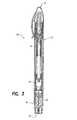
図面、特に、図1〜図3を参照すると、本開示に従うシリンジ10の典型的な実施形態が示されている。シリンジ10は、注入アセンブリ12、薬剤カートリッジ14、及び引き込みアセンブリ16を有する。DETAILED DESCRIPTION OF THE INVENTION With reference to the drawings, and in particular with reference to FIGS. 1-3, an exemplary embodiment of a
図2を参照すると、好都合にも、シリンジ10は、使用者又はヘルスケア(医療)提供者(例えば、薬剤師、医師、看護師)が組み立てることのできるマルチコンポーネント装置である。シリンジ10の典型的な実施形態は、製造時における組み立てを必要としないため、本開示によれば、薬剤カートリッジ14の使用期限をシリンジ10の使用期限から効果的に切り離すことができる。例えば、典型的な流感ワクチンの使用期限は1年である。従って、使用者は、任意の使用期限の切れた薬剤カートリッジ14を取り替えるだけで、本開示の注入アセンブリ12及び引き込みアセンブリ16の供給を維持することができる。 With reference to FIG. 2, the
シリンジ10は、好ましくは、アセンブリ内から皮下注射針を伸ばし、カートリッジ14から1回分の予め測定された用量の薬剤を使用者の内部へ注入(注射)し、そして注入が完了した後にアセンブリ内へと皮下注射針を自動的に引き込む自動注入装置である。シリンジ10は、使用者に対して配置するための注入端部18と、注入アセンブリ12を始動(作動)させるための始動端部20とを画成する。 The
図4を参照して注入アセンブリ12の動作を説明する。注入アセンブリ12は、注入バネ22、プランジャ24、始動ボタン26、デカプラ(分離器)28、及びカップリング(連結器)30を有する。注入バネ22は、キャプチャ42とカップリング30との間においてプランジャ24の周囲に配置されている。注入バネ22は、カップリング30によってプランジャ24に駆動可能なように係合されている。 The operation of the
始動ボタン26は、始動端部20に画成されている。始動ボタン26は、上端部32及び下端部34を有する。上端部32は、注入アセンブリ12から外側に向けて突き出ている。下端部34は、内側に向けて延在しており、そして注入バネ22内のエネルギーを解放してプランジャ24を推進するためにプランジャ24を係止面44との係合から選択的に解放するように構成されている。図示の実施形態では、プランジャ24は、係止端部36及び駆動端部38を有する。係止端部36は2個以上の歯40を有しており、これらの歯40は各々が互いに離れるように弾性的に外側に向けて付勢されている。駆動端部38は、後述して詳しく説明するようにして、薬剤カートリッジ14に作用するように構成されている。 The
注入アセンブリ12は、各歯40が互いに離れるように付勢されている時に各歯40の係止面44と係合するキャプチャ42を有する。始動ボタン26は、下端部34に画成された解放面46を有する。始動ボタン26の上端部32に対して適用された力によって、解放面46は、注入アセンブリ12内の一定の位置にとどまっているキャプチャ42から係止面44が解放(解除)されるように、分岐(二股)状の各歯40をお互いに向けて圧縮する。 The
プランジャ24は、注入バネ22を、通常はカップリング30とキャプチャ42との間で圧縮された、即ち、圧力を加えられた状態に維持している。歯40がキャプチャ42から解放されると、バネ22に蓄積されていたエネルギーがプランジャ24を注入方向48に向けて推進する。注入バネ22の作用を受けてプランジャ24が方向48に向けて移動すると、引き込みアセンブリ16にエネルギーが与えられるようになる。 Plunger 24 maintains
注入バネ22は、カップリング30が摺動可能なようにデカプラ28に当接するまで、プランジャ24を注入方向48に向けて推進する。カップリング30にかかる注入バネ22の力は、カップリングをデカプラ28に係合させる。これにより、カップリングは、瞬間的に開き、該カップリングのプランジャ24との放射方向(円形状)の干渉による係合から解放される。カップリング30のプランジャ24からの解放は、プランジャ24に対する注入バネ22の作用を終了させ、そしてエネルギーを与えられた引き込みアセンブリ16の作用によってプランジャが引き込み方向50に向けて移動させられることを可能とする。 The
シリンジ10は、カートリッジ14からの薬剤を、筋肉注射、皮下注射及び/又は皮内注射により注入するように構成することができる。例えば、デカプラ28は、注入方向48及び/又は引き込み方向50に沿って移動させ得るように注入アセンブリ12内に固定することができる。デカプラ28の移動は、デカプラが注入バネ22をプランジャ24から外すポイントを変更することによって、注入アセンブリ12のストローク(行程)を変更することができる。
図4に示された実施形態を参照すると、注入アセンブリ12は、始動ボタン26を覆って配置された安全キャップ52を有する。安全キャップ52は、始動ボタン26が不用意に押されることを軽減することができ、従って注入アセンブリ12が早まって始動させられることを防止することができる。 With reference to the embodiment shown in FIG. 4, the
上述のように、シリンジ10は、製造時に組み立てる必要はない。図2を参照して、シリンジ10の組み立てについて説明する。カートリッジ14は、薬剤バイアル(薬瓶)54、可動ピストン56、及び端部キャップ58を有する。端部キャップ58は、穿刺(貫通)可能な隔膜60を有する。 As described above, the
カートリッジ14は、端部キャップ58が注入端部18に向き、又ピストン56が始動端部20に向くように、引き込みアセンブリ16内に挿入される。カートリッジ14が引き込みアセンブリ16内に取り付けられると、引き込みアセンブリと注入アセンブリ12とを互いに動作可能なように固定することができる。組み立てられた状態において、注入アセンブリ12を始動させることにより、プランジャ24の駆動端部38は、注入方向48に向けて移動し、ピストン56に接触するようになる。カートリッジ14の内部の流体薬剤は非圧縮性であるため、プランジャ24によってピストン56に適用された力は、注入方向48に向けてカートリッジ14を平行移動させる。注入方向48に向けたカートリッジの平行移動は、引き込みバネ70にエネルギーを与え、又皮下注射針72に下部シール78及び注入部位(注射部位)の組織を貫かせる。次いで、穿刺可能な隔膜60が穿刺され、又ピストン56がカートリッジ14から薬剤を押し出す(放出する)。 The
好ましい一実施形態では、注入アセンブリ12と引き込みアセンブリ16とは、注入後に両アセンブリをお互いから取り外すことができないように、スナップフィット方式で互いに永久的に固定される。例えば、図4及び図10を参照すると、注入アセンブリ12は、外側に設けられた1個以上のタブ62を有していてよく、これは引き込みアセンブリ16に画成された対応する数の開口部64内に受容される。注入アセンブリ12が引き込みアセンブリ16内に挿入されると、タブ62は、引き込みアセンブリに作用して、管の内部の寸法を弾性的に変形させる。タブ62が開口部64によって受容されると、引き込みアセンブリ16の内部の寸法は、その元の寸法に戻り、タブを開口部内に固定する。 In a preferred embodiment, the
組み立てられた状態において、注入アセンブリ12と引き込みアセンブリ16とは、好ましくは、カートリッジ14を、それらの間で密閉された状態に維持する。例えば、注入アセンブリ12は、これに限定されるわけではないが、Oリングなどの封止部材66を有していてよい。注入アセンブリ12と引き込みアセンブリ16とが一緒に固定されると、封止部材66は引き込みアセンブリ16の内側及び注入アセンブリ12の外側と弾性的に協働して、放射方向(円形状)の密封部を形成する。図示の実施形態では、封止部材66は、引き込みアセンブリ16に画成された開口部64より下に位置しており、タブ62と開口部64との間のスナップフィット結合部より下に密封部を提供する。 In the assembled state, the
図5〜図8を参照すると、引き込みアセンブリ16は、カートリッジ14と協働するように設計されており、管状部分86、引き込みバネ70、皮下注射針72、上部シール74、針ハブ83、端部キャップ76、及び下部シール78を有する。 5-8, the
上部シール74は、カートリッジ14のキャップ58を受容するように構成されている。上部シール74は、引き込みアセンブリ16の内径に画成された面状(上部)の封止面80及び/又は円形状(放射方向,側部)の封止面81に対して(接触して)密封部を形成するように構成されている。 The
シリンジ10の始動前には、引き込みバネ70は、針ハブ83と端部キャップ76との間で部分的(ある程度)に付勢されている。後述する理由で、引き込みバネ70は、注入バネ22よりも低いバネ定数を有する。部分的に付勢された状態において、引き込みバネ70は、針ハブ83を注入方向48とは反対方向に押圧して、上部シール74を、面状の封止面80に接触した状態、従って面状の封止面80に対して密封された状態に維持する。始動前には、皮下注射針72は、完全に上部シール74と下部シール78との間の密閉された容積内にとどまっている。 Prior to starting the
この状態において、引き込みバネ70は、上部シール74が引き込みアセンブリ16内の封止面80に対して密封された状態を維持する。従って、使用するまで上部シール74と下部シール78との間の皮下注射針72を収容している滅菌された容積が維持されるように、製造中に引き込みアセンブリ16を最後に滅菌することができる。 In this state, the
針72は、第1の先端(即ち、薬剤入口先端)82と、第2の先端(即ち、組織穿刺及び薬剤出口先端)84とを有する、両端が相似(両頭)の皮下注射針である。入口先端82は上部シール74に近接して配置され、一方、出口先端84は下部シール78に近接して配置される。 The
シリンジ10の使用中に、プランジャ24の移動は、薬剤カートリッジ14を上部シール74に向けて注入方向48に推進し、これによって入口先端82が上部シール及び隔膜60を突き通し、針がカートリッジとの流体連通状態に置かれる。又、薬剤カートリッジ14内の薬剤は非圧縮性の流体であるため、プランジャ24の更なる移動は、引き込みバネ70の力に打ち勝つことで針72を注入方向48に向けて推進する。従って、出口先端84は、下部シール78を突き通し、そして注入部位の組織内に挿入される。最後に、プランジャ24の移動は、プランジャ24を注入方向48に向けて推進し、これによってカートリッジ14内の薬剤が出口先端84を通して使用者の内部へ放出される。 During use of the
例えば、図6には、完全に組み立てられた状態にあるシリンジ10が示されており、ここではカートリッジ14は引き込みアセンブリ16内に配置され、又注入アセンブリ12は引き込みアセンブリに固定されている。この状態では、端部キャップ58が上部シール74によって封止係合されており、これによって端部キャップの隔膜60が第1の先端82と整列している。 For example, FIG. 6 shows the
図7には、注入アセンブリ12の始動後のシリンジ10が示されている。この状態では、注入バネ22がプランジャ24を薬剤カートリッジ14内へと駆動し、これによってプランジャの駆動端部38がピストン56と係合する。注入バネ22は、引き込みバネ70の力に打ち勝って引き込みバネを圧縮し、又カートリッジ14を注入方向48に向けて移動させ、これによって端部キャップ58が上部シール74を第1の先端82へと変形させる。このようにして、第1の先端82が上部シール74と隔膜60との両方を突き通して、針72をカートリッジ14との流体連通状態に置く。 In FIG. 7, the
注入バネ22が針72を注入方向48に向けて移動させ、これによって第2の先端84が下部シール78を突き通し、又使用者の皮膚に入る。更に、注入バネ22がプランジャ24の駆動端部38を注入方向48に向けて移動させ、薬剤を第2の先端84を通してカートリッジから放出する。 The
カートリッジ14からの薬剤の注入を完了するまでピストン56が移動したポイントでは、プランジャ24は、デカプラ28にカップリング30をプランジャ24から解放させ、従って注入バネ22をプランジャ24から解放させるのに十分な量だけ注入方向48に向けて移動している。注入バネ22が解放されると、図8に示すように、引き込みバネ70は、針72、カートリッジ14、及びプランジャ24を、引き込み方向50に向けて引き込みアセンブリ16内へと推進して戻す。注入アセンブリ12が引き込みアセンブリ16に永久的に固定される実施形態では、針72が引き込みアセンブリ内に引き戻されることは、使用後のシリンジを取り扱う可能性のある者が使用済みの針によって不意の被害を受ける虞に関してシリンジ10を安全とし、従ってシリンジ10の廃棄を安全とする。 At the point where the
引き込みアセンブリ16の一実施形態では、管状部分86は透明であってよい。シリンジ10が組み立てられると、透明な管状部分86は、使用者及び医療提供者がカートリッジ14を見ること、カートリッジ内の適正な投薬容量を確認すること、薬剤溶液が劣化していないことを確認すること、及び使用後において全用量が投与されたことを確認することを可能とする。 In one embodiment of the
好都合にも、引き込みアセンブリ16は、両側性の針をその内部に密封された状態で維持する。従って、引き込みアセンブリ16は、薬剤カートリッジ14とは別個に、最終的に滅菌し、又滅菌状態に維持することができる。シリンジ10が組み立てられると、薬剤カートリッジ14は、注入アセンブリ12と引き込みアセンブリ16との間に密閉される。 Conveniently, the
本開示の一実施形態では、シリンジ10は、組み立てて使用するための、組み立てられていない状態にて最終的に滅菌されたキット(図示せず)として提供することができる。この場合、キットは、注入アセンブリ12及び引き込みアセンブリ16を有していてよい。幾つかの実施形態では、キットは薬剤カートリッジ14を有していてよいが、他の実施形態では、薬剤カートリッジは別個に販売されてもよい。更に、キットは、予め包装されたアルコールスワブなどの、1つ以上の注入部位清浄化スワブ(綿棒)も有していてよい。例えば、注入アセンブリ12、引き込みアセンブリ16、及び清浄化スワブは、プラスチック又はTYVECパッケージなどの、密閉されたパッケージ内に収容することができる。幾つかの実施形態では、パッケージは最終的に滅菌することができる。 In one embodiment of the present disclosure, the
図9及び図10を参照すると、本開示に従うシリンジ10の別の典型的な実施形態が示されている。シリンジ10は、注入アセンブリ12、薬剤カートリッジ14、及び引き込みアセンブリ16を有する。ここで、注入アセンブリ12は、図1〜図8を参照して上述したものと同様である。 Referring to FIGS. 9 and 10, another exemplary embodiment of a
この実施形態では、薬剤カートリッジ14は、薬剤バイアル54及び可動ピストン56、並びに、それと共に一体的に形成された単一の先端の針72を有する。ここで、薬剤カートリッジ14は、使用時に薬剤で満たされてもよいし、シリンジ10の組み立て前に薬剤で満たされてもよい。 In this embodiment, the
カートリッジ14は、針72が注入端部18に向き、又ピストン56が始動端部20に向くように、引き込みアセンブリ16内に挿入される。カートリッジが引き込みアセンブリ16内に取り付けられると、引き込みアセンブリと注入アセンブリ12とを互いに動作可能なように固定することができる。組み立てられた状態において、注入アセンブリ12と引き込みアセンブリ16とは、好ましくは、カートリッジ14を、それらの間で密閉された状態に維持する。 The
図10に示すように、引き込みアセンブリ16は、引き込みバネ70、端部キャップ76、下部シール78、バネ保持体85、及び管状部分86を有する。シリンジ10の始動前には、引き込みバネ70は、バネ保持体85と端部キャップ76との間で部分的に付勢されている。部分的に付勢された状態において、引き込みバネ70は、バネ保持体85を注入方向48とは反対方向に推進して、バネ保持体を面80に対して当接された状態に維持する。このようにして、バネ保持体85は、引き込みバネ70を端部キャップ76内の所望の位置に保持し、そして注入アセンブリ12との組み立ての前に引き込みバネが引き込みアセンブリ16から抜け落ちるのを防止する。 As shown in FIG. 10, the
更に、バネ保持体85は、針案内チャネル(経路)87を有していてよい。チャネル87は、薬剤カートリッジ14の針72が適切に引き込みアセンブリ16内へ挿入されることを確実にする。又、バネ保持体85は、始動中の衝撃を吸収し又弱めるためのバンパー89を有していてよい。 Further, the
好都合にも、本開示に従うシリンジ10は、組み立てて使用するための、組み立てられていない状態にて最終的に滅菌されたキット(図示せず)として提供することができる。この場合、キットは、注入アセンブリ12、薬剤カートリッジ14(図2又は図9)、及び引き込みアセンブリ16(図8又は図10)を有していてよい。従って、このキットは、使用者又はヘルスケア提供者が、単に薬剤カートリッジ14を引き込みアセンブリ16内に取り付けて、注入アセンブリ12を引き込みアセンブリに固定することによって、シリンジ10を使用のために準備することを可能とする。幾つかの実施形態では、キットは、予め包装されたアルコールスワブなどの1つ以上の注入部位清浄化スワブ、又は粘着性包帯(絆創膏)などその他の注射用付属品を有していてよい。 Conveniently, the
図11及び図12を参照すると、注入アセンブリ12の他の典型的な実施形態が示されている。ここでもまた、シリンジ10は、使用者又はヘルスケア提供者が組み立てるための、引き込みアセンブリ16から分離された注入アセンブリ12を有して提供される。好都合にも、注入アセンブリ12は、組み立て前に注入バネ22がプランジャ24を注入アセンブリから排出してしまうことを防止するための安全要素110を有していてよい。 Referring to FIGS. 11 and 12, another exemplary embodiment of the
安全要素110は、プランジャ24の一部に、注入バネ22の内径よりも小さいが、デカプラ28の内径よりも大きな外部寸法を与える。従って、安全要素110は、引き込みアセンブリ16との最終的な組み立ての前に注入アセンブリが始動された場合に、プランジャ24が注入アセンブリ12から脱落する(抜ける)のを防止し、一方で注入バネ22を通したプランジャ24の適正な移動を可能とする。 The
図11及び図12に示される実施形態では、安全要素110は、プランジャ24の外周の周りに動作可能なように接続されたリングとして示されている。勿論、本開示は、安全要素110がその他の、リングではない形状を有することも意図しており、それはカップリング30と歯40との間に入る位置においてプランジャ24の外周の一部のみから延在したものである。更に、別の好ましい実施形態として、安全要素110が、プランジャ24の一体的に形成された形状(機構)であることも意図する。 In the embodiment shown in FIGS. 11 and 12, the
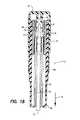
図13〜図15を参照すると、本開示に従うプランジャの典型的な実施形態が示されている。上述のように、プランジャ24は、係止端部36及び駆動端部38を有する。係止端部36は、係止面44がパワーパックアセンブリ12のキャプチャ42(図4)に係合するように、弾性的に外側へ向けて付勢された分岐(二股)状の歯40を有する。この位置において、プランジャ24は、注入バネ22を圧縮された、即ち、圧力を加えられた状態に維持する。そのため、係止端部36は、注入バネ22の力に拘わらず、分岐状の歯40が外側に向けて付勢された位置に維持されることを確実にするように、十分な弾力性(弾性)を有する。更に、係止端部36は、注入バネ22の力に拘わらず、係止面44がキャプチャ42と係合したままとなることを確実にするように、十分な構造的剛性を有する。 With reference to FIGS. 13-15, an exemplary embodiment of a plunger according to the present disclosure is shown. As described above, the
図13〜図15に示す複合材料(コンポジット)プランジャが、上記弾力性及び構造的剛性特性を提供し、しかも全て金属のプランジャに比べて費用(コスト)と製造所要時間を低減することが本開示によって見出された。図示の複合材料プランジャ24は、金属(製)係止端部36と、プラスチック(製)駆動端部38とを有する。 The composite material (composite) plunger shown in FIGS. 13-15 provides the elasticity and structural stiffness characteristics described above, yet further reduces costs and manufacturing time compared to an all-metal plunger. It was found by. The illustrated
製造中に、金属係止端部36は、一般的な打ち抜き(打ち抜き型での圧断(型押し))工程によって、平坦な供給材料から画成することができる。次に、金属係止端部36は、歯40を画成するように曲げることができる。金属係止端部36が完成したら、その金属係止端部を、複合材料プランジャ24を画成するように、プラスチック駆動端部38中に挿入成型することができる。好ましい一実施形態では、成型されたプラスチック駆動端部38は、それと共に一体的に成型された安全要素110を有していてよい。 During manufacturing, the
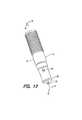
図16を参照すると、シリンジ10の別の典型的な実施形態が、組み立てられた状態で示されている。ここでもまた、シリンジ10は、注入アセンブリ12、薬剤カートリッジ14、及び引き込みアセンブリ16を有しており、これは使用者又はヘルスケア提供者(例えば、薬剤師、医師、看護師)によって組み立てることができる。シリンジ10は、筋肉注射に特に適している。 Referring to FIG. 16, another exemplary embodiment of the
簡潔さを期すために、薬剤カートリッジ14及び引き込みアセンブリ16は、図1、図2、及び図5〜図8を参照して説明したものと実質的に同様である。又、シリンジ10の組み立ては、図2を参照して上述したものと実質的に同様である。 For the sake of brevity, the
一方、図16の注入アセンブリ12の動作は、図17〜図20を参照して説明する。 Meanwhile, the operation of the
注入アセンブリ12は、注入バネ22、プランジャ24、始動ボタン26、及びカップリング30を有する。注入バネ22は、プランジャ24の周囲に配置され、又カップリング30によってプランジャに駆動可能なように係合されている。 The
始動ボタン26は、上端部32及び下端部34を有する。シリンジ10の注入アセンブリ12は、始動ボタン26を掴み、注入端部18を注入部位に対して押圧することによって始動される。始動ボタン26を握りながら注入端部18を注入部位に押し付けることは、始動ボタンが押し下げられること、従ってシリンジ10が始動されることを引き起こす。 The
幾つかの実施形態では、始動ボタン26は、使用者が始動ボタンを把持することを補助するために、外部シュラウド(側板)108を有する。好ましい一実施形態では、シュラウド108は、使用者が始動ボタン26を把持することを補助するために、多数の長手方向のリブ109を有していてよい。このようにすれば、注入アセンブリ12は、使用者が保護手袋を着用している時などであり得る、使用者が通常の手先の器用さを欠いていることのある状況での使用のために特に適している。他の実施形態では、シュラウド108及び/又は長手方向のリブ109は、使用者が注入アセンブリ12を把持することを更に補助するために、エラストマー材料(弾性材料)で形成することができる。 In some embodiments, the
他の実施形態では、外部シュラウド108及び注入アセンブリ12は、始動装置が所定の位置へと回転させられた後にだけ始動ボタン26の押し下げを可能とする、1個以上の協働するガイド(図示せず)を有していてよい。つまり、外部シュラウド108及び注入アセンブリ12は、注入バネ22を始動するために回転及び押し下げの2方向における動作を所定の順番で行うことを要求するように、協働することができる。ここで、長手方向のリブ109は、使用者が回転させることも補助することができる。 In other embodiments, the
上端部32は、注入アセンブリ12から外部に向けて突き出ている。下端部34は、内側に向けて延在しており、又プランジャ24をキャプチャ42から選択的に解放して、注入バネ22がプランジャ24を駆動することを可能とするように構成されている。図示の実施形態では、プランジャ24は、係止端部36及び駆動端部38を有する。係止端部36は2個以上の歯40を有しており、これらの歯40は各々が互いに離れるように弾性的に外側に向けて付勢されている。駆動端部38は、後述して詳しく説明するようにして、薬剤カートリッジ14に作用するように構成されている。 The
注入アセンブリ12は、各歯40が互いに離れるように付勢されている時に各歯40の係止面44と係合するキャプチャ42を有する。始動ボタン26は、下端部34に画成された解放面46を有する。注入端部18が注入部位に対して(接触して)保持されている間に始動ボタン26の上端部32に対して方向48に向けて適用された力によって、解放面46は、係止面44がキャプチャ42から解放されるように、分岐状の各歯40をお互いに向けて圧縮する。 The
始動前には、注入バネ22は、通常は、カップリング30とキャプチャ42との間で付勢された、即ち、圧力を加えられた状態に維持される。歯40がキャプチャ42から解放されると、バネ22に蓄積されたエネルギーがプランジャ24を注入方向48に向けて推進する。 Prior to start-up, the
カップリング30は、外側に向けて付勢されたバネ部材であり、特に図19〜図20を参照して説明する。組み立て中に、カップリング30は、内側に配置されたカップリングの雄形状(機構)が対応するプランジャの雌形状(機構)に係合するまで、プランジャ24に向けて内側へと圧縮される。プランジャ24が移動している間は、カップリング30は、注入バネ22とプランジャ24との間の駆動的係合を維持する。 The
より詳細には、注入アセンブリ12は、通路120を有しており、この通路120は、図19に示すように、カップリング30を圧縮された位置に維持してプランジャ24との係合を維持するように、十分な半径方向(放射方向)の拘束力を維持する第1の内径112を有する。通路120は、プランジャ24のストロークの終わりの位置に逃げ部(逃げ口)114を有する。注入バネ22は、カップリング30が逃げ部114に到達するまで、プランジャ24を注入方向48に向けて駆動する。図20に示すように、カップリング30の弾力性は、カップリングを、逃げ部114内へと広げ、又プランジャ24から解放させる。カップリング30のプランジャ24からの解放は、プランジャを注入バネ22の力から解放し、従ってプランジャが引き込みアセンブリ16によって引き込み方向50に向けて移動させられることを可能とする。 More particularly,
注入アセンブリ12と引き込みアセンブリ16とは、スナップフィット方式で互いに固定することができる。例えば、注入アセンブリ12は、外側に設けられた1個以上のタブ62を有していてよく、これは引き込みアセンブリ16に画成された対応する数の開口部64内に受容される。組み立てられた状態において、注入アセンブリ12及び引き込みアセンブリ16は、例えば封止部材66などの手段により、カートリッジ14をそれらの間で密閉された状態に維持する。 The
本明細書では、「第1」、「第2」、「第3」、「上」、「下」などの用語が、種々の要素を修飾するために使用されていることがある。これらの修飾語は、特に言及しない限り、修飾される要素について空間的、連続的、又は階層的な序列を意味するものではない。 As used herein, terms such as “first”, “second”, “third”, “upper”, “lower”, etc. may be used to modify various elements. These modifiers do not imply a spatial, continuous, or hierarchical order with respect to the modified elements, unless otherwise noted.
本開示は1つ又はそれ以上の典型的な実施形態を参照して説明してきたが、当業者は、本開示の範囲から逸脱することなく種々の変更を行うことができ、又その要素を均等物で置換することができることを理解するだろう。又、特定の状況又は材料を本開示の範囲から逸脱することなく本開示の教示に適合させるように多くの修飾を行うことができる。従って、本開示は、考えられる最良の形態として開示された特定の実施形態に限定されるものではなく、添付の特許請求の範囲内にあるすべての実施形態を包含することを意図するものである。 Although the present disclosure has been described with reference to one or more exemplary embodiments, various modifications can be made by those skilled in the art without departing from the scope of the disclosure, and the elements may be equally You will understand that they can be replaced with objects. In addition, many modifications may be made to adapt a particular situation or material to the teachings of the disclosure without departing from the scope of the disclosure. Accordingly, the present disclosure is not intended to be limited to the particular embodiments disclosed as the best mode contemplated, but is intended to encompass all embodiments within the scope of the appended claims. .
Claims (30)
Translated fromJapanese薬剤カートリッジと、
注入アセンブリと、
前記薬剤カートリッジをその中に収容するための、前記注入アセンブリに選択的に固定可能な引き込みアセンブリと、
を有し、前記引き込みアセンブリは、
端部キャップと、
針ハブを有する皮下注射針と、
前記針ハブと前記端部キャップとの間に配置され、それらの間で部分的に圧縮された状態に維持された引き込みバネと、
第1の密封部を形成するための、前記部分的に圧縮された状態にある前記引き込みバネによって前記引き込みアセンブリの面状の封止面に対して押圧された上部シールと、
を有する注入及び引き込みシリンジ。An injecting and retracting syringe,
A drug cartridge;
An injection assembly;
A retraction assembly selectively securable to the infusion assembly for receiving the drug cartridge therein;
The retraction assembly comprises:
An end cap;
A hypodermic needle having a needle hub;
A retraction spring disposed between the needle hub and the end cap and maintained in a partially compressed state therebetween;
An upper seal pressed against the planar sealing surface of the retracting assembly by the retracting spring in the partially compressed state to form a first seal;
Injection and retraction syringes.
薬剤カートリッジと、
注入アセンブリと、
前記薬剤カートリッジをその中に収容するための、前記注入アセンブリに選択的に固定可能な引き込みアセンブリと、
を有し、前記引き込みアセンブリは、
端部キャップと、
バネ保持体と、
引き込みバネであって、前記バネ保持体と前記端部キャップとの間に配置され、前記バネ保持体が該引き込みバネによって前記引き込みアセンブリの面状の封止面に対して押圧されている時に、前記バネ保持体と前記端部キャップとの間で部分的に圧縮された状態に維持される引き込みバネと、
を有する注入及び引き込みシリンジ。An injecting and retracting syringe,
A drug cartridge;
An injection assembly;
A retraction assembly selectively securable to the infusion assembly for receiving the drug cartridge therein;
The retraction assembly comprises:
An end cap;
A spring holder,
A retraction spring, disposed between the spring retainer and the end cap, wherein the spring retainer is pressed against the planar sealing surface of the retraction assembly by the retraction spring; A retraction spring maintained in a partially compressed state between the spring holder and the end cap;
Injection and retraction syringes.
薬剤カートリッジと、
注入アセンブリと、
前記薬剤カートリッジをその中に収容するための、前記注入アセンブリに選択的に固定可能な引き込みアセンブリと、
を有し、前記注入アセンブリは、
通常の圧力が加えられた状態から選択的に解放可能な注入バネと、
前記注入バネに駆動可能なように係合されたプランジャと、
前記プランジャ上に画成された安全要素であって、前記引き込みアセンブリが前記注入アセンブリに固定される前に前記注入バネが前記通常の圧力が加えられた状態から解放された場合に前記プランジャが前記注入アセンブリから抜けるのを防止する安全要素と、
を有する注入及び引き込みシリンジ。An injecting and retracting syringe,
A drug cartridge;
An injection assembly;
A retraction assembly selectively securable to the infusion assembly for receiving the drug cartridge therein;
The injection assembly comprises:
An injection spring that can be selectively released from a state in which normal pressure is applied;
A plunger operably engaged with the injection spring;
A safety element defined on the plunger, wherein the plunger is released when the injection spring is released from the normal pressure before the retraction assembly is secured to the injection assembly; A safety element to prevent it from exiting the injection assembly;
Injection and retraction syringes.
端部キャップと、
針ハブを有する皮下注射針と、
前記針ハブと前記端部キャップとの間で部分的に圧縮された状態に維持された引き込みバネと、
第1の密封部を形成するための、前記部分的に圧縮された状態にある前記引き込みバネによって前記引き込みアセンブリの面状の封止面に対して押圧された上部シールと、
を有する請求項8に記載のシリンジ。The retraction assembly is
An end cap;
A hypodermic needle having a needle hub;
A retraction spring maintained in a partially compressed state between the needle hub and the end cap;
An upper seal pressed against the planar sealing surface of the retracting assembly by the retracting spring in the partially compressed state to form a first seal;
The syringe of Claim 8 which has these.
端部キャップと、
バネ保持体と、
引き込みバネであって、前記バネ保持体と前記端部キャップとの間に配置され、前記バネ保持体が該引き込みバネによって前記引き込みアセンブリの面状の封止面に対して押圧されている時に、前記バネ保持体と前記端部キャップとの間で部分的に圧縮された状態に維持される引き込みバネと、
を有する請求項8に記載のシリンジ。The retraction assembly is
An end cap;
A spring holder,
A retraction spring disposed between the spring retainer and the end cap, wherein the spring retainer is pressed against the planar sealing surface of the retraction assembly by the retraction spring; A retraction spring maintained in a partially compressed state between the spring holder and the end cap;
The syringe of Claim 8 which has these.
注入アセンブリと、
引き込みアセンブリと、
を有し、
前記注入アセンブリと前記引き込みアセンブリとは、互いに選択的に固定可能である注入キット。An infusion kit,
An injection assembly;
A retraction assembly;
Have
An infusion kit wherein the infusion assembly and the retraction assembly are selectively securable to each other.
端部キャップと、
針ハブを有する皮下注射針と、
前記針ハブと前記端部キャップとの間で部分的に圧縮された状態に維持された引き込みバネと、
第1の密封部を形成するための、前記部分的に圧縮された状態にある前記引き込みバネによって前記引き込みアセンブリの面状の封止面に対して押圧された上部シールと、
を有する請求項19に記載の注入キット。The retraction assembly is
An end cap;
A hypodermic needle having a needle hub;
A retraction spring maintained in a partially compressed state between the needle hub and the end cap;
An upper seal pressed against the planar sealing surface of the retracting assembly by the retracting spring in the partially compressed state to form a first seal;
The injection kit according to claim 19, comprising:
端部キャップと、
バネ保持体と、
引き込みバネであって、前記バネ保持体と前記端部キャップとの間に配置され、前記バネ保持体が該引き込みバネによって前記引き込みアセンブリの面状の封止面に対して押圧されている時に、前記バネ保持体と前記端部キャップとの間で部分的に圧縮された状態に維持される引き込みバネと、
を有する請求項19に記載の注入キット。The retraction assembly is
An end cap;
A spring holder,
A retraction spring disposed between the spring retainer and the end cap, wherein the spring retainer is pressed against the planar sealing surface of the retraction assembly by the retraction spring; A retraction spring maintained in a partially compressed state between the spring holder and the end cap;
The injection kit according to claim 19, comprising:
通常の圧力が加えられた状態から選択的に解放可能な注入バネと、
前記注入バネに駆動可能なように係合されたプランジャと、
前記プランジャ上に画成された安全要素であって、前記引き込みアセンブリが前記注入アセンブリに固定される前に前記注入バネが前記通常の圧力が加えられた状態から解放された場合に前記プランジャが前記注入アセンブリから抜けるのを防止する安全要素と、
を有する請求項19に記載の注入キット。The injection assembly includes
An injection spring that can be selectively released from a state in which normal pressure is applied;
A plunger operably engaged with the injection spring;
A safety element defined on the plunger, wherein the plunger is released when the injection spring is released from the normal pressure before the retraction assembly is secured to the injection assembly; A safety element to prevent it from exiting the injection assembly;
The injection kit according to claim 19, comprising:
Applications Claiming Priority (3)
| Application Number | Priority Date | Filing Date | Title |
|---|---|---|---|
| US63448604P | 2004-12-09 | 2004-12-09 | |
| US60/634,486 | 2004-12-09 | ||
| PCT/US2005/044411WO2006063124A2 (en) | 2004-12-09 | 2005-12-08 | Automatic injection and retraction syringe |
Publications (2)
| Publication Number | Publication Date |
|---|---|
| JP2008522751Atrue JP2008522751A (en) | 2008-07-03 |
| JP5198072B2 JP5198072B2 (en) | 2013-05-15 |
Family
ID=36578562
Family Applications (3)
| Application Number | Title | Priority Date | Filing Date |
|---|---|---|---|
| JP2007545641APendingJP2008522754A (en) | 2004-12-09 | 2005-12-08 | Retrofit type fixed needle syringe and automatic injection apparatus having the same |
| JP2007545616AActiveJP4588072B2 (en) | 2004-12-09 | 2005-12-08 | Coupling for automatic injection equipment |
| JP2007545617AActiveJP5198072B2 (en) | 2004-12-09 | 2005-12-08 | Automatic injection and retraction syringe |
Family Applications Before (2)
| Application Number | Title | Priority Date | Filing Date |
|---|---|---|---|
| JP2007545641APendingJP2008522754A (en) | 2004-12-09 | 2005-12-08 | Retrofit type fixed needle syringe and automatic injection apparatus having the same |
| JP2007545616AActiveJP4588072B2 (en) | 2004-12-09 | 2005-12-08 | Coupling for automatic injection equipment |
Country Status (10)
| Country | Link |
|---|---|
| US (3) | US20060178642A1 (en) |
| EP (3) | EP1819380B1 (en) |
| JP (3) | JP2008522754A (en) |
| CN (3) | CN101146562B (en) |
| AU (3) | AU2005314034A1 (en) |
| BR (3) | BRPI0518978A2 (en) |
| CA (3) | CA2591278A1 (en) |
| IL (3) | IL183768A0 (en) |
| MX (3) | MX2007006974A (en) |
| WO (3) | WO2006063123A2 (en) |
Cited By (11)
| Publication number | Priority date | Publication date | Assignee | Title |
|---|---|---|---|---|
| JP2011212183A (en)* | 2010-03-31 | 2011-10-27 | Terumo Corp | Prefilled syringe |
| JP2011528573A (en)* | 2008-07-18 | 2011-11-24 | ベクトン・ディキンソン・アンド・カンパニー | Cartridge stopper for intradermal administration system |
| JP2012245178A (en)* | 2011-05-27 | 2012-12-13 | Yoshino Kogyosho Co Ltd | Cartridge for syringe |
| JP2013507215A (en)* | 2009-10-16 | 2013-03-04 | サノフィ−アベンティス・ドイチュラント・ゲゼルシャフト・ミット・ベシュレンクテル・ハフツング | Cartridge holder assembly for drug delivery devices |
| JP2014503298A (en)* | 2010-12-31 | 2014-02-13 | ノボ・ノルデイスク・エー/エス | Medical injection device |
| JP2016503406A (en)* | 2012-11-05 | 2016-02-04 | パラティン テクノロジーズ, インコーポレイテッドPalatin Technologies, Inc. | Use of bremeranotide in the treatment of female sexual dysfunction |
| JP2016537114A (en)* | 2013-11-18 | 2016-12-01 | デュオジェクト・メディカル・システムズ・インコーポレイテッド | Auto injector |
| JP2019517358A (en)* | 2016-06-09 | 2019-06-24 | ベクトン・ディキンソン・アンド・カンパニーBecton, Dickinson And Company | Drive assembly and spacer for drug delivery system |
| JP2024517407A (en)* | 2021-04-14 | 2024-04-22 | ウエスト ファーマスーティカル サービシーズ インコーポレイテッド | Syringe Parts |
| JP2024517404A (en)* | 2021-04-14 | 2024-04-22 | ウエスト ファーマスーティカル サービシーズ インコーポレイテッド | Syringe power pack |
| US12171807B2 (en) | 2020-01-21 | 2024-12-24 | Cosette Pharmaceuticals, Inc. | Use of bremelanotide in patients with controlled hypertension |
Families Citing this family (125)
| Publication number | Priority date | Publication date | Assignee | Title |
|---|---|---|---|---|
| GB2414399B (en) | 2004-05-28 | 2008-12-31 | Cilag Ag Int | Injection device |
| GB2414406B (en)* | 2004-05-28 | 2009-03-18 | Cilag Ag Int | Injection device |
| GB2414409B (en) | 2004-05-28 | 2009-11-18 | Cilag Ag Int | Injection device |
| GB2414402B (en) | 2004-05-28 | 2009-04-22 | Cilag Ag Int | Injection device |
| GB2414403B (en) | 2004-05-28 | 2009-01-07 | Cilag Ag Int | Injection device |
| GB2414775B (en) | 2004-05-28 | 2008-05-21 | Cilag Ag Int | Releasable coupling and injection device |
| GB2414400B (en) | 2004-05-28 | 2009-01-14 | Cilag Ag Int | Injection device |
| GB2414401B (en) | 2004-05-28 | 2009-06-17 | Cilag Ag Int | Injection device |
| CA2581595A1 (en) | 2004-09-27 | 2006-04-06 | Medical Instill Technologies, Inc. | Laterally-actuated dispenser with one-way valve for storing and dispensing metered amounts of substances |
| US7731678B2 (en)* | 2004-10-13 | 2010-06-08 | Hyprotek, Inc. | Syringe devices and methods for mixing and administering medication |
| US7648482B2 (en) | 2004-11-22 | 2010-01-19 | Intelliject, Inc. | Devices, systems, and methods for medicament delivery |
| WO2006057636A1 (en) | 2004-11-22 | 2006-06-01 | Intelliject, Llc | Devices, systems, and methods for medicament delivery |
| US10737028B2 (en) | 2004-11-22 | 2020-08-11 | Kaleo, Inc. | Devices, systems and methods for medicament delivery |
| US11590286B2 (en) | 2004-11-22 | 2023-02-28 | Kaleo, Inc. | Devices, systems and methods for medicament delivery |
| US7648483B2 (en) | 2004-11-22 | 2010-01-19 | Intelliject, Inc. | Devices, systems and methods for medicament delivery |
| US7947017B2 (en)* | 2004-11-22 | 2011-05-24 | Intelliject, Inc. | Devices, systems and methods for medicament delivery |
| US8123724B2 (en) | 2004-12-09 | 2012-02-28 | West Pharmaceutical Services Of Delaware, Inc. | Auto-injection syringe having vent device |
| MX2007006974A (en) | 2004-12-09 | 2007-10-11 | West Pharm Serv Inc | Automatic injection and retraction syringe. |
| US8361026B2 (en)* | 2005-02-01 | 2013-01-29 | Intelliject, Inc. | Apparatus and methods for self-administration of vaccines and other medicaments |
| AU2006210865B2 (en) | 2005-02-01 | 2008-12-04 | Kaleo, Inc. | Devices, systems, and methods for medicament delivery |
| GB2427826B (en) | 2005-04-06 | 2010-08-25 | Cilag Ag Int | Injection device comprising a locking mechanism associated with integrally formed biasing means |
| GB2424835B (en) | 2005-04-06 | 2010-06-09 | Cilag Ag Int | Injection device (modified trigger) |
| GB2425062B (en) | 2005-04-06 | 2010-07-21 | Cilag Ag Int | Injection device |
| GB2424836B (en) | 2005-04-06 | 2010-09-22 | Cilag Ag Int | Injection device (bayonet cap removal) |
| GB2424838B (en) | 2005-04-06 | 2011-02-23 | Cilag Ag Int | Injection device (adaptable drive) |
| PL1759729T3 (en) | 2005-08-30 | 2010-09-30 | Cilag Gmbh Int | Needle assembly for a prefilled syringe system |
| US20110098656A1 (en) | 2005-09-27 | 2011-04-28 | Burnell Rosie L | Auto-injection device with needle protecting cap having outer and inner sleeves |
| JP2009519047A (en) | 2005-11-09 | 2009-05-14 | ハイプロテック、 インク. | Syringe device, syringe device component, and method of forming component and syringe device |
| US7988675B2 (en) | 2005-12-08 | 2011-08-02 | West Pharmaceutical Services Of Delaware, Inc. | Automatic injection and retraction devices for use with pre-filled syringe cartridges |
| GB2438593B (en) | 2006-06-01 | 2011-03-30 | Cilag Gmbh Int | Injection device (cap removal feature) |
| GB2438591B (en) | 2006-06-01 | 2011-07-13 | Cilag Gmbh Int | Injection device |
| GB2438592B (en)* | 2006-06-01 | 2011-04-06 | Cilag Gmbh Int | Injection device |
| GB2438590B (en) | 2006-06-01 | 2011-02-09 | Cilag Gmbh Int | Injection device |
| KR101396797B1 (en)* | 2006-06-30 | 2014-05-26 | 애브비 바이오테크놀로지 리미티드 | Automatic injection device |
| US7618396B2 (en)* | 2006-08-09 | 2009-11-17 | Avant Medical Corp. | Injection system with hidden needles |
| ATE529147T1 (en)* | 2006-08-23 | 2011-11-15 | Medtronic Minimed Inc | SYSTEMS AND METHODS FOR FILLING CONTAINERS AND DISPENSING AN INFUSION MEDIA |
| FR2905273B1 (en)* | 2006-09-06 | 2009-04-03 | Becton Dickinson France Soc Pa | AUTOMATIC INJECTION DEVICE WITH TIMING MEANS. |
| WO2008061041A2 (en)* | 2006-11-11 | 2008-05-22 | Medical Instill Technologies, Inc. | Multiple dose delivery device with manually depressible actuator and one-way valve for storing and dispensing substances, and related method |
| EP2125572A2 (en)* | 2006-11-29 | 2009-12-02 | West Pharmaceutical Services, Inc. | Syringe cartridge system |
| EP3108812B1 (en)* | 2007-03-07 | 2020-04-29 | Becton, Dickinson and Company | Safety blood collection assembly with indicator |
| JP5362591B2 (en)* | 2007-03-09 | 2013-12-11 | イーライ リリー アンド カンパニー | Delay mechanism for automatic injection equipment |
| BRPI0817907B8 (en) | 2007-10-02 | 2021-06-22 | Lamodel Ltd | apparatus for administering a substance to an individual |
| US9522097B2 (en) | 2007-10-04 | 2016-12-20 | Hyprotek, Inc. | Mixing/administration syringe devices, protective packaging and methods of protecting syringe handlers |
| US8002737B2 (en) | 2007-10-04 | 2011-08-23 | Hyprotek, Inc. | Mixing/administration syringe devices, protective packaging and methods of protecting syringe handlers |
| CN103041478B (en)* | 2008-04-10 | 2015-01-21 | 松下健康医疗控股株式会社 | Medication administering device |
| FR2929854B1 (en)* | 2008-04-10 | 2010-05-28 | Primequal Sa | METHOD FOR MANUFACTURING DISPOSABLE EJECTION DEVICE |
| DK2296732T3 (en)* | 2008-06-11 | 2014-04-07 | Shl Group Ab | DRUG DELIVERY DEVICES |
| GB2461086B (en) | 2008-06-19 | 2012-12-05 | Cilag Gmbh Int | Injection device |
| GB2461087B (en) | 2008-06-19 | 2012-09-26 | Cilag Gmbh Int | Injection device |
| GB2461084B (en)* | 2008-06-19 | 2012-09-26 | Cilag Gmbh Int | Fluid transfer assembly |
| GB2461089B (en)* | 2008-06-19 | 2012-09-19 | Cilag Gmbh Int | Injection device |
| GB2461085B (en) | 2008-06-19 | 2012-08-29 | Cilag Gmbh Int | Injection device |
| US12097357B2 (en) | 2008-09-15 | 2024-09-24 | West Pharma. Services IL, Ltd. | Stabilized pen injector |
| WO2010081489A1 (en)* | 2009-01-15 | 2010-07-22 | Tecpharma Licensing Ag | Apparatus for administering an injectable product |
| WO2010127487A1 (en)* | 2009-05-07 | 2010-11-11 | 明辰股份有限公司 | Automatic retractable safe injector for non-liquid medicine |
| AU2010303704B2 (en)* | 2009-10-05 | 2014-05-15 | Graphic Packaging International, Inc. | Carrier for containers |
| EP2512558A4 (en)* | 2009-12-15 | 2014-08-13 | Abbvie Biotechnology Ltd | IMPROVED TRIP PUSHER FOR AUTOMATIC INJECTION DEVICE |
| ES2484266T3 (en) | 2010-03-01 | 2014-08-11 | Eli Lilly And Company | Automatic injection device with delay mechanism including a double function thrust element |
| SG194370A1 (en) | 2010-06-07 | 2013-11-29 | Amgen Inc | Drug delivery device |
| US8939943B2 (en) | 2011-01-26 | 2015-01-27 | Kaleo, Inc. | Medicament delivery device for administration of opioid antagonists including formulations for naloxone |
| US9173999B2 (en) | 2011-01-26 | 2015-11-03 | Kaleo, Inc. | Devices and methods for delivering medicaments from a multi-chamber container |
| US8627816B2 (en) | 2011-02-28 | 2014-01-14 | Intelliject, Inc. | Medicament delivery device for administration of opioid antagonists including formulations for naloxone |
| CN103458943A (en)* | 2011-01-31 | 2013-12-18 | Shl集团有限责任公司 | Coupling arrangement |
| CN102151347B (en)* | 2011-04-23 | 2012-10-24 | 任梅芳 | Portable insulin injection syringe |
| JP6139521B2 (en)* | 2011-07-19 | 2017-05-31 | サノフィ−アベンティス・ドイチュラント・ゲゼルシャフト・ミット・ベシュレンクテル・ハフツング | Cartridge holder for drug delivery device |
| US20130261591A1 (en)* | 2012-03-28 | 2013-10-03 | C. Garyen Denning | Vial device and methods |
| CN204379913U (en)* | 2012-04-09 | 2015-06-10 | 贝克顿·迪金森公司 | Medicine bottle dosing mechanism and molectron |
| KR20150119092A (en) | 2013-03-14 | 2015-10-23 | 일라이 릴리 앤드 캄파니 | Delay mechanism suitable for compact automatic injection device |
| MX2015013058A (en) | 2013-03-14 | 2016-05-31 | Lilly Co Eli | Trigger assembly for an automatic injection device. |
| USD739011S1 (en)* | 2013-03-15 | 2015-09-15 | Eli Lilly And Company | Automatic injection device |
| GB2515038A (en) | 2013-06-11 | 2014-12-17 | Cilag Gmbh Int | Injection device |
| GB2515039B (en) | 2013-06-11 | 2015-05-27 | Cilag Gmbh Int | Injection Device |
| GB2517896B (en) | 2013-06-11 | 2015-07-08 | Cilag Gmbh Int | Injection device |
| GB2515032A (en) | 2013-06-11 | 2014-12-17 | Cilag Gmbh Int | Guide for an injection device |
| WO2014205604A1 (en)* | 2013-06-28 | 2014-12-31 | 群康生技股份有限公司 | Syringe |
| ES2706738T3 (en) | 2013-08-29 | 2019-04-01 | Sanofi Sa | Cap for a medication container |
| USD743539S1 (en)* | 2013-09-11 | 2015-11-17 | Samsung Electronics Co., Ltd. | Blood collection device |
| WO2015118550A2 (en) | 2014-02-10 | 2015-08-13 | Elcam Medical Agricultural Cooperative Association Ltd. | Semi disposable auto injector |
| USD793547S1 (en) | 2014-04-10 | 2017-08-01 | Merck Sharp & Dohme Corp. | Autoinjector pen |
| USD780909S1 (en) | 2014-04-10 | 2017-03-07 | Merck Sharp & Dohme Corp. | Autoinjector pen |
| EP3145561A1 (en) | 2014-05-20 | 2017-03-29 | Cequr SA | Medicine delivery device with restricted access filling port |
| RU2017121580A (en)* | 2014-07-11 | 2018-12-21 | Джей-Ник Пти Лтд. | SYRINGE |
| US9517307B2 (en) | 2014-07-18 | 2016-12-13 | Kaleo, Inc. | Devices and methods for delivering opioid antagonists including formulations for naloxone |
| EP3177914B1 (en)* | 2014-08-08 | 2024-10-30 | Sanofi-Aventis Deutschland GmbH | Method and system for acoustically testing the mechanical integrity of a cartridge |
| USD773647S1 (en) | 2014-08-27 | 2016-12-06 | Merck Sharp & Dohme Corp. | Medical injector pen |
| USD777907S1 (en) | 2014-08-27 | 2017-01-31 | Merck Sharp & Dohme Corp. | Medical injector pen |
| USD773646S1 (en) | 2014-08-27 | 2016-12-06 | Merck Sharp & Dohme Corp | Medical injector pen |
| USD752210S1 (en) | 2014-08-27 | 2016-03-22 | Merck Sharp & Dohme Corp. | Medical injector pen |
| USD777908S1 (en) | 2014-08-27 | 2017-01-31 | Merck Sharp & Dohme Corp. | Medical injector pen |
| US10226585B2 (en)* | 2014-10-01 | 2019-03-12 | Allergan, Inc. | Devices for injection and dosing |
| US10799634B2 (en) | 2014-11-12 | 2020-10-13 | Novo Nordisk A/S | Method of manufacturing one of a range of autoinjectors |
| US20160144123A1 (en)* | 2014-11-26 | 2016-05-26 | John Berndt | Syringe adapter |
| CA3009221A1 (en) | 2014-12-23 | 2016-06-30 | Automed Pty Ltd | Delivery apparatus, system and associated methods |
| US9415176B1 (en) | 2015-01-22 | 2016-08-16 | West Pharmaceutical Services, Inc. | Autoinjector having an end-of-dose visual indicator |
| EP3061479A1 (en)* | 2015-02-27 | 2016-08-31 | Sanofi-Aventis Deutschland GmbH | Sealed needle assembly for medicament delivery device |
| IL295010B1 (en) | 2015-03-10 | 2025-06-01 | Regeneron Pharma | Pollution-free piercing system and method |
| CN106267462A (en)* | 2015-05-25 | 2017-01-04 | 美敦力公司 | For the fluid infusion apparatus that patient is administered |
| CA2990950A1 (en) | 2015-06-30 | 2017-01-05 | Kaleo, Inc. | Auto-injectors for administration of a medicament within a prefilled syringe |
| US10850036B2 (en) | 2015-08-27 | 2020-12-01 | E3D Agricultural Cooperative Association | Reusable automatic injection device |
| US10576207B2 (en) | 2015-10-09 | 2020-03-03 | West Pharma. Services IL, Ltd. | Angled syringe patch injector |
| US11318254B2 (en) | 2015-10-09 | 2022-05-03 | West Pharma. Services IL, Ltd. | Injector needle cap remover |
| SG10201509159TA (en)* | 2015-11-05 | 2017-06-29 | Arrow-Med Design Pte Ltd | Injection device |
| JP6964584B2 (en) | 2015-11-27 | 2021-11-10 | サノフィ−アベンティス・ドイチュラント・ゲゼルシャフト・ミット・ベシュレンクテル・ハフツング | Drug injection device with spring-supported protective needle cap |
| US10646643B2 (en) | 2016-01-21 | 2020-05-12 | West Pharma. Services IL, Ltd. | Needle insertion and retraction mechanism |
| EP3711793B1 (en) | 2016-01-21 | 2021-12-01 | West Pharma Services IL, Ltd. | A method of connecting a cartridge to an automatic injector |
| JP6885960B2 (en) | 2016-01-21 | 2021-06-16 | ウェスト ファーマ サービシーズ イスラエル リミテッド | Drug delivery device with visual indicators |
| US11389597B2 (en) | 2016-03-16 | 2022-07-19 | West Pharma. Services IL, Ltd. | Staged telescopic screw assembly having different visual indicators |
| CN109475466B (en) | 2016-07-22 | 2021-09-28 | 艾斯曲尔医疗公司 | Medicament container holder for a medicament delivery device and method of assembling a medicament delivery device |
| US11338090B2 (en) | 2016-08-01 | 2022-05-24 | West Pharma. Services IL, Ltd. | Anti-rotation cartridge pin |
| JP7059251B2 (en) | 2016-08-01 | 2022-04-25 | ウェスト ファーマ サービシーズ イスラエル リミテッド | A spring that prevents the door from closing halfway |
| WO2018119218A1 (en) | 2016-12-23 | 2018-06-28 | Kaleo, Inc. | Medicament delivery device and methods for delivering drugs to infants and children |
| US10435226B2 (en)* | 2016-12-27 | 2019-10-08 | Doselogix, Llc | Dosing dispenser system |
| US11040181B2 (en) | 2017-01-04 | 2021-06-22 | Reflex Medical Corp. | Metered dose topical applicator |
| CN119950880A (en) | 2017-05-05 | 2025-05-09 | 里珍纳龙药品有限公司 | Auto-injectors and related methods of use |
| EP3630226A1 (en) | 2017-05-30 | 2020-04-08 | West Pharma. Services Il, Ltd. | Modular drive train for wearable injector |
| JP1631347S (en)* | 2017-11-06 | 2019-05-13 | ||
| US11583633B2 (en) | 2018-04-03 | 2023-02-21 | Amgen Inc. | Systems and methods for delayed drug delivery |
| CN109646144A (en)* | 2018-12-17 | 2019-04-19 | 唐山爱在云端网络科技有限公司 | Push type syringe |
| CN113242743A (en)* | 2018-12-19 | 2021-08-10 | 赛诺菲 | Plastic primary package for an injection device |
| JP7489392B2 (en) | 2019-01-24 | 2024-05-23 | サノフイ | Drug Delivery Devices |
| CA3145580A1 (en) | 2019-08-09 | 2021-02-18 | Kaleo, Inc. | Devices and methods for delivery of substances within a prefilled syringe |
| US11957542B2 (en) | 2020-04-30 | 2024-04-16 | Automed Patent Holdco, Llc | Sensing complete injection for animal injection device |
| US12268847B1 (en) | 2021-02-10 | 2025-04-08 | Kaleo, Inc. | Devices and methods for delivery of substances within a medicament container |
| USD1007676S1 (en) | 2021-11-16 | 2023-12-12 | Regeneron Pharmaceuticals, Inc. | Wearable autoinjector |
| WO2025132497A1 (en)* | 2023-12-21 | 2025-06-26 | Sanofi | Medicament container, injection device and method of filling the same |
Citations (4)
| Publication number | Priority date | Publication date | Assignee | Title |
|---|---|---|---|---|
| JPS63290577A (en)* | 1987-04-20 | 1988-11-28 | ハブレイ・メディカル・テクノロジー・コーポレーション | Syringe |
| JPH0716296A (en)* | 1993-06-29 | 1995-01-20 | Yoshikuni Saito | Injector hub, connecting structure for the hub, injector using the hub and assembly method for the injector |
| JP2003505159A (en)* | 1999-07-27 | 2003-02-12 | ファルマ・コンスルト・ゲーエーエスエムベーハー | Device for automatically injecting injection solutions |
| JP2004516074A (en)* | 2000-12-21 | 2004-06-03 | ジレスピー、リチャード・ディー・ザ・サード | Automatic compounding, syringe |
Family Cites Families (144)
| Publication number | Priority date | Publication date | Assignee | Title |
|---|---|---|---|---|
| US2561233A (en)* | 1949-03-19 | 1951-07-17 | Abbott Lab | Hypodermic syringe |
| US2684068A (en)* | 1951-02-21 | 1954-07-20 | Sindey R Orens | Syringe |
| BE541390A (en)* | 1955-10-18 | |||
| US3306290A (en) | 1964-02-14 | 1967-02-28 | Harold S Weltman | Automatically retractable needle syringe |
| US3489147A (en)* | 1964-07-21 | 1970-01-13 | Joseph Denman Shaw | Combination mixing and injecting medical syringe |
| US3477432A (en)* | 1964-07-21 | 1969-11-11 | Joseph Denman Shaw | Combination mixing and injecting medical syringe |
| US3572336A (en)* | 1968-04-30 | 1971-03-23 | Daniel R Hershberg | Syringe |
| BE756550A (en)* | 1969-09-23 | 1971-03-01 | Sherwood Medical Ind Inc | REAR LOADING SYRINGE AND PROCEDURE FOR ITS FILLING |
| US3707968A (en)* | 1970-10-07 | 1973-01-02 | Sherwood Medical Ind Inc | Arming cap for breech loaded syringe |
| US3708089A (en)* | 1971-01-11 | 1973-01-02 | North American Rockwell | Gas generator for liquid sprayers |
| BE795162A (en) | 1972-02-10 | 1973-08-08 | Philips Nv | INJEKTIE-INRICHTING |
| US3834387A (en)* | 1972-08-10 | 1974-09-10 | Sherwood Medical Ind Inc | Breech loaded syringe with deformable piston |
| US3901402A (en)* | 1973-03-14 | 1975-08-26 | Becton Dickinson Co | Stopper-piston |
| US4059109A (en) | 1976-07-27 | 1977-11-22 | Tischlinger Edward A | Mixing and dispensing disposable medicament injector |
| US4445895A (en) | 1981-07-16 | 1984-05-01 | Sterling Drug Inc. | Prepackaged, disposable hypodermic syringes |
| IT1206220B (en)* | 1981-09-30 | 1989-04-14 | Caselgrandi Ivo Palmieri Benia | SYRINGE PARTICULARLY SUITABLE FOR NEEDLE BIOPSIES WITH A DEVICE THAT ALLOWS THE SUCTION PHASE, GENERATED BY THE RETROSE STROKE STROKE AUTOMATICALLY |
| USD287603S (en) | 1983-12-19 | 1987-01-06 | Koh-I-Noor Rapidograph, Inc. | Writing pen |
| USD286164S (en) | 1983-12-19 | 1986-10-14 | Koh-I-Noor Rapidograph, Inc. | Writing pen |
| US4581016A (en)* | 1984-02-29 | 1986-04-08 | Gettig Pharmaceutical Instrument Co. | Dual cartridge wet/dry syringe |
| FR2573310B1 (en)* | 1984-11-20 | 1988-12-30 | Poutrait Morin | BULB FOR HYPODERMIC SYRINGE, IN PARTICULAR SELF-INJECTING SYRINGE |
| US4689042A (en)* | 1985-05-20 | 1987-08-25 | Survival Technology, Inc. | Automatic medicament ingredient mixing and injecting apparatus |
| US4861335A (en) | 1985-07-26 | 1989-08-29 | Duoject Medical Systems Inc. | Syringe |
| DE3673317D1 (en)* | 1985-10-11 | 1990-09-13 | Duphar Int Res | AUTOMATIC SYRINGE. |
| US4795444A (en) | 1986-05-02 | 1989-01-03 | Sunstar Kabushiki Kaisha | Syringe |
| ATE67414T1 (en)* | 1986-05-15 | 1991-10-15 | Duphar Int Res | AUTOMATIC INJECTION SYRINGE. |
| GB8702069D0 (en)* | 1987-01-30 | 1987-03-04 | High Trees Agriculture Ltd | Cleaning agricultural sprayers |
| US4886495A (en) | 1987-07-08 | 1989-12-12 | Duoject Medical Systems Inc. | Vial-based prefilled syringe system for one or two component medicaments |
| JP2584462B2 (en)* | 1987-09-18 | 1997-02-26 | ベクトン・ディッキンソン・アンド・カンパニー | Single use disposable syringe |
| GB8723454D0 (en)* | 1987-10-06 | 1987-11-11 | Beecham Group Plc | Device |
| USRE35986E (en)* | 1988-08-23 | 1998-12-08 | Meridian Medical Technologies, Inc. | Multiple chamber automatic injector |
| US4968877A (en)* | 1988-09-14 | 1990-11-06 | Sensor Frame Corporation | VideoHarp |
| US4969877A (en) | 1988-10-19 | 1990-11-13 | The Pascall Medical Corporation | Syringe |
| ES2009709A6 (en)* | 1989-01-24 | 1989-10-01 | Villar Pascual Jose Antonio | Single-use safety syringe |
| US5169385A (en) | 1989-01-26 | 1992-12-08 | Turnbull Christopher J | Safety I. V. drug introducer set |
| US5085641A (en)* | 1989-07-17 | 1992-02-04 | Survival Technology, Inc. | Conveniently carried frequent use auto-injector with improved cap structure |
| US5102393A (en) | 1989-07-17 | 1992-04-07 | Survival Technology, Inc. | Autoinjector converted from intramuscular to subcutaneous mode of injection |
| US5085642A (en)* | 1989-07-17 | 1992-02-04 | Survival Technology, Inc. | Conveniently carried frequent use autoinjector |
| US4998922A (en)* | 1990-02-23 | 1991-03-12 | Kuracina Thomas C | Safety syringe cap minimizing needle-stick probability |
| US5092843A (en)* | 1990-04-12 | 1992-03-03 | Survival Technology, Inc. | Dispersion multichamber auto-injector |
| GB9019538D0 (en)* | 1990-09-07 | 1990-10-24 | Philips Electronic Associated | Tracking a moving object |
| CA2054664C (en)* | 1990-11-30 | 1996-06-11 | Nesbitt D. Brown | Hydrolytic stabilizer for unstable organic ions |
| GB9100819D0 (en) | 1991-01-15 | 1991-02-27 | Medimech Int Ltd | Subcutaneous injector |
| US5188613A (en)* | 1991-04-03 | 1993-02-23 | Shaw Thomas J | Nonreusable syringe with safety indicator |
| US5120310A (en)* | 1991-04-03 | 1992-06-09 | Shaw Thomas J | Nonreusable syringe |
| US5267961A (en) | 1991-04-03 | 1993-12-07 | Shaw Thomas J | Nonreusable syringe with safety indicator |
| US5176643A (en)* | 1991-04-29 | 1993-01-05 | George C. Kramer | System and method for rapid vascular drug delivery |
| GB9111600D0 (en)* | 1991-05-30 | 1991-07-24 | Owen Mumford Ltd | Improvements relating to injection devices |
| USD339606S (en) | 1991-11-08 | 1993-09-21 | Rotring-Werke Riepe, KG | Fountain pen |
| GB9200219D0 (en)* | 1992-01-07 | 1992-02-26 | Medimech Int Ltd | Automatic injectors |
| US5176657A (en)* | 1992-01-15 | 1993-01-05 | Shields Jack W | Shot gun syringe with cartridge and scabbards |
| US5324273A (en) | 1992-09-30 | 1994-06-28 | Centrix, Inc. | Disposable barrel dental impression material syringe |
| US5411487A (en)* | 1992-12-07 | 1995-05-02 | Castagna; John F. | Hypodermic syringe with automatic needle cover |
| US5373684A (en)* | 1992-12-14 | 1994-12-20 | Mallinckrodt Medical, Inc. | Process and apparatus used in producing prefilled, sterile delivery devices |
| US5383865A (en)* | 1993-03-15 | 1995-01-24 | Eli Lilly And Company | Medication dispensing device |
| EP0693946B1 (en)* | 1993-03-24 | 2001-05-16 | Owen Mumford Limited | Improvements relating to injection devices |
| GB9310163D0 (en) | 1993-05-18 | 1993-06-30 | Owen Mumford Ltd | Improvements relating to injection devices |
| US5358489A (en) | 1993-05-27 | 1994-10-25 | Washington Biotech Corporation | Reloadable automatic or manual emergency injection system |
| US5540664A (en)* | 1993-05-27 | 1996-07-30 | Washington Biotech Corporation | Reloadable automatic or manual emergency injection system |
| US5364363A (en)* | 1993-07-08 | 1994-11-15 | Survival Technology, Inc. | Rectal administrator |
| US5425715A (en)* | 1993-08-05 | 1995-06-20 | Survival Technology, Inc. | Reloadable injector |
| US5385551A (en) | 1993-09-22 | 1995-01-31 | Shaw; Thomas J. | Nonreusable medical device with front retraction |
| US5620421A (en) | 1993-12-09 | 1997-04-15 | Schmitz; William L. | Syringe injector system |
| US5423758A (en)* | 1993-12-16 | 1995-06-13 | Shaw; Thomas J. | Retractable fluid collection device |
| FR2715071B1 (en) | 1994-01-17 | 1996-03-01 | Aguettant Lab | Automatic drug injector. |
| US5413564A (en) | 1994-03-02 | 1995-05-09 | Silver; Jules | Predetermined dosage hypodermic syringe system |
| US5389076A (en) | 1994-04-05 | 1995-02-14 | Shaw; Thomas J. | Single use medical device with retraction mechanism |
| US5411489A (en)* | 1994-05-06 | 1995-05-02 | Sterling Winthrop Inc. | Pre-filled syringe and pre-filled cartridge having actuating cylinder/plunger rod combination for reducing syringing force |
| AU1994295A (en) | 1994-05-16 | 1995-12-05 | Washington Biotech Corporation | Modular automatic or manual emergency medicine injection system |
| GB9412301D0 (en)* | 1994-06-17 | 1994-08-10 | Safe T Ltd | Hollow-needle drugs etc applicators |
| US5466223A (en)* | 1994-06-20 | 1995-11-14 | Becton, Dickinson And Company | Needle assembly having single-handedly activatable needle barrier |
| US5545145A (en)* | 1994-08-16 | 1996-08-13 | Becton Dickinson And Company | Pen needle despenser |
| US5637092A (en) | 1995-01-30 | 1997-06-10 | Shaw; Thomas J. | Syringe plunger locking assembly |
| US5685846A (en) | 1995-02-27 | 1997-11-11 | Schott Parenta Systems, Inc. | Dual chamber internal by-pass syringe assembly |
| JP3568959B2 (en) | 1995-03-07 | 2004-09-22 | イーライ・リリー・アンド・カンパニー | Reusable dosing device |
| WO1996029107A1 (en) | 1995-03-17 | 1996-09-26 | Radiometer Medical A/S | Shielding means |
| US5876372A (en)* | 1995-03-22 | 1999-03-02 | Abbott Laboratories | Syringe system accomodating seperate prefilled barrels for two constituents |
| US5637087A (en)* | 1995-03-22 | 1997-06-10 | Abbott Laboratories | Prefilled, two-constituent syringe |
| FR2733155B1 (en)* | 1995-04-18 | 1997-09-19 | Tebro | RECHARGEABLE SELF-INJECTOR |
| US5578011A (en) | 1995-05-11 | 1996-11-26 | Shaw; Thomas J. | Tamperproof retractable syringe |
| US5632733A (en) | 1995-05-11 | 1997-05-27 | Shaw; Thomas J. | Tamperproof retractable syringe |
| US5688251A (en)* | 1995-09-19 | 1997-11-18 | Becton Dickinson And Company | Cartridge loading and priming mechanism for a pen injector |
| US5674204A (en)* | 1995-09-19 | 1997-10-07 | Becton Dickinson And Company | Medication delivery pen cap actuated dose delivery clutch |
| DK0928182T3 (en) | 1996-01-11 | 2002-08-26 | Duoject Inc | Delivery system for medicines packed in pharmaceutical bottles |
| FR2749169B1 (en) | 1996-06-04 | 1998-08-21 | Delab | PROCESS FOR CONSTITUTING AN INJECTABLE PREPARATION AND DEVICE FOR CARRYING OUT SAID METHOD |
| US5718690A (en) | 1996-06-10 | 1998-02-17 | Gettig Technologies, Incorporated | Hypodermic injector system and method for maintaining the sterility thereof prior to use |
| JPH1057483A (en) | 1996-08-23 | 1998-03-03 | Material Eng Tech Lab Inc | Syringe and manufacture thereof |
| US5817058A (en) | 1996-12-23 | 1998-10-06 | Shaw; Thomas J. | Retractable catheter introducer structure |
| US5779679A (en) | 1997-04-18 | 1998-07-14 | Shaw; Thomas J. | Winged IV set with retractable needle |
| US5810775A (en) | 1997-05-23 | 1998-09-22 | Shaw; Thomas J. | Cap operated retractable medical device |
| USD423577S (en)* | 1997-07-03 | 2000-04-25 | Sanford, L.P. | Writing implement having a grooved grip |
| US5921966A (en)* | 1997-08-11 | 1999-07-13 | Becton Dickinson And Company | Medication delivery pen having an improved clutch assembly |
| US5873462A (en) | 1997-09-12 | 1999-02-23 | Becton Dickinson And Company | Pen needle dispenser |
| US5941857A (en)* | 1997-09-12 | 1999-08-24 | Becton Dickinson And Company | Disposable pen needle |
| US5931817A (en) | 1997-09-12 | 1999-08-03 | Becton Dickinson And Company | Pen needle assembly |
| US5944700A (en)* | 1997-09-26 | 1999-08-31 | Becton, Dickinson And Company | Adjustable injection length pen needle |
| US6015438A (en) | 1997-11-14 | 2000-01-18 | Retractable Technologies Inc. | Full displacement retractable syringe |
| WO1999030759A2 (en)* | 1997-12-16 | 1999-06-24 | Meridian Medical Technologies, Inc. | Automatic injector for administrating a medicament |
| US5961495A (en)* | 1998-02-20 | 1999-10-05 | Becton, Dickinson And Company | Medication delivery pen having a priming mechanism |
| US6221053B1 (en) | 1998-02-20 | 2001-04-24 | Becton, Dickinson And Company | Multi-featured medication delivery pen |
| US6001082A (en)* | 1998-02-20 | 1999-12-14 | Becton Dickinson And Company | Medication delivery pen with an integral magnifying pocket clip |
| US6248095B1 (en)* | 1998-02-23 | 2001-06-19 | Becton, Dickinson And Company | Low-cost medication delivery pen |
| US5997512A (en) | 1998-03-04 | 1999-12-07 | Shaw; Thomas J. | Retractable dental syringe |
| US6221055B1 (en) | 1998-03-04 | 2001-04-24 | Retractable Technologies, Inc. | Retractable dental syringe |
| US6200627B1 (en) | 1998-03-17 | 2001-03-13 | Becton, Dickinson And Company | Low silicone glass prefillable syringe |
| US6243938B1 (en) | 1998-03-17 | 2001-06-12 | Becton, Dickinson And Company | Low silicone plastic prefillable syringe |
| US5989220A (en) | 1998-05-26 | 1999-11-23 | Retractable Technologies Inc. | Self-retracting IV catheter introducer |
| USD414807S (en)* | 1998-05-29 | 1999-10-05 | Sanford Corporation | Writing instrument grip |
| KR20010071512A (en) | 1998-07-20 | 2001-07-28 | 찰스 더블유 프란즈 | Brachytherapy Device Including An Anti-Static Handle |
| US6346094B2 (en) | 1998-09-28 | 2002-02-12 | Becton, Dickinson And Company | Pen needle magazine |
| USD414201S (en)* | 1998-09-29 | 1999-09-21 | Sanford Corporation | Double-ended marking pen |
| US6086563A (en) | 1999-01-13 | 2000-07-11 | Becton, Dickinson And Company | Needle retraction mechanism with push start retraction |
| USD425120S (en)* | 1999-01-20 | 2000-05-16 | Sanford roting Holding GmbH | Writing instrument |
| US6095814A (en) | 1999-01-29 | 2000-08-01 | 3M Innovative Properties Company | Dispensing cartridge with stepped chamber |
| US6210371B1 (en)* | 1999-03-30 | 2001-04-03 | Retractable Technologies, Inc. | Winged I.V. set |
| WO2000062839A2 (en)* | 1999-04-16 | 2000-10-26 | Becton Dickinson And Company | Pen style injector with automated substance combining feature |
| JP2000334041A (en)* | 1999-05-28 | 2000-12-05 | Kooki Engineering:Kk | Syringe |
| US6277099B1 (en)* | 1999-08-06 | 2001-08-21 | Becton, Dickinson And Company | Medication delivery pen |
| US6328715B1 (en) | 1999-09-21 | 2001-12-11 | William B. Dragan | Unit dose low viscosity material dispensing system |
| US20020193740A1 (en)* | 1999-10-14 | 2002-12-19 | Alchas Paul G. | Method of intradermally injecting substances |
| US6241710B1 (en) | 1999-12-20 | 2001-06-05 | Tricardia Llc | Hypodermic needle with weeping tip and method of use |
| DE10006474A1 (en)* | 2000-02-14 | 2001-08-16 | Transcoject Gmbh | Filling syringe for medical and other purposes, comprises removal of gas (mixture) from the syringe cylinder through hole in the piston face and subsequent plugging of this hole |
| USD446242S1 (en)* | 2000-02-22 | 2001-08-07 | Sanford Gmbh | Writing instrument |
| US6213597B1 (en) | 2000-02-29 | 2001-04-10 | Win-Yin Liu | Apparatus for ink cartridge of a jet printer |
| US6572584B1 (en) | 2000-08-07 | 2003-06-03 | Retractable Technologies, Inc. | Retractable syringe with reduced retraction force |
| USD452271S1 (en)* | 2000-08-24 | 2001-12-18 | Sanford | Writing instrument |
| USD441398S1 (en)* | 2000-08-24 | 2001-05-01 | Sanford | Writing instrument |
| US6413237B1 (en)* | 2000-08-31 | 2002-07-02 | Becton, Dickinson And Company | Hypodermic syringe with selectively retractable needle |
| US7470258B2 (en) | 2001-03-13 | 2008-12-30 | Mdc Investment Holdings, Inc. | Pre-filled safety vial injector |
| US20020164265A1 (en) | 2001-05-04 | 2002-11-07 | Hetzler Kevin G. | Method of removing refractive defects in cyclic olefin medical devices |
| US7186241B2 (en)* | 2001-10-03 | 2007-03-06 | Medical Instill Technologies, Inc. | Syringe with needle penetrable and laser resealable stopper |
| US6796697B1 (en)* | 2001-10-04 | 2004-09-28 | Kla-Tencor, Inc. | Illumination delivery system |
| US6494863B1 (en)* | 2001-10-15 | 2002-12-17 | Retractable Technologies, Inc. | One-use retracting syringe with positive needle retention |
| US6796967B2 (en)* | 2001-10-22 | 2004-09-28 | Nps Pharmaceuticals, Inc. | Injection needle assembly |
| US6872193B2 (en) | 2001-10-26 | 2005-03-29 | Retractable Technologies, Inc. | IV catheter introducer with retractable needle |
| US6802828B2 (en)* | 2001-11-23 | 2004-10-12 | Duoject Medical Systems, Inc. | System for filling and assembling pharmaceutical delivery devices |
| JP2003199825A (en)* | 2001-12-28 | 2003-07-15 | Terumo Corp | Prefilled syringe |
| US6616640B2 (en) | 2002-01-07 | 2003-09-09 | Marina Ling-Ko Chen | Syringe with plunger anti-detachment mechanism |
| US6743194B2 (en) | 2002-03-28 | 2004-06-01 | Igal Sharon | Multi-compartment syringe |
| DK1503816T3 (en)* | 2002-05-02 | 2007-04-23 | Pa Consulting Services | injection device |
| AU2003257994A1 (en)* | 2002-07-31 | 2004-02-16 | Alza Corporation | Injection device providing automatic needle retraction |
| US6884237B2 (en) | 2002-12-10 | 2005-04-26 | Inviro Medical Devices, Inc. | Position guide for a needle guard |
| CN2595375Y (en)* | 2003-01-12 | 2003-12-31 | 周永君 | Self injection needle feeder |
| DE10340585A1 (en) | 2003-09-03 | 2005-04-07 | Tecpharma Licensing Ag | Administration device with multi-chamber ampoule and mixing stop |
| MX2007006974A (en) | 2004-12-09 | 2007-10-11 | West Pharm Serv Inc | Automatic injection and retraction syringe. |
- 2005
- 2005-12-08MXMX2007006974Apatent/MX2007006974A/enunknown
- 2005-12-08BRBRPI0518978-0Apatent/BRPI0518978A2/ennot_activeApplication Discontinuation
- 2005-12-08MXMX2007006975Apatent/MX2007006975A/enunknown
- 2005-12-08AUAU2005314034Apatent/AU2005314034A1/ennot_activeAbandoned
- 2005-12-08EPEP05853354.8Apatent/EP1819380B1/enactiveActive
- 2005-12-08JPJP2007545641Apatent/JP2008522754A/enactivePending
- 2005-12-08USUS11/297,159patent/US20060178642A1/ennot_activeAbandoned
- 2005-12-08BRBRPI0518960-8Apatent/BRPI0518960A2/ennot_activeApplication Discontinuation
- 2005-12-08CACA002591278Apatent/CA2591278A1/ennot_activeAbandoned
- 2005-12-08EPEP05853353.0Apatent/EP1819386B1/enactiveActive
- 2005-12-08WOPCT/US2005/044410patent/WO2006063123A2/enactiveSearch and Examination
- 2005-12-08CACA002591420Apatent/CA2591420A1/ennot_activeAbandoned
- 2005-12-08CACA002590281Apatent/CA2590281A1/ennot_activeAbandoned
- 2005-12-08JPJP2007545616Apatent/JP4588072B2/enactiveActive
- 2005-12-08USUS11/296,973patent/US7674246B2/enactiveActive
- 2005-12-08CNCN2005800472942Apatent/CN101146562B/enactiveActive
- 2005-12-08USUS11/297,225patent/US7758548B2/enactiveActive
- 2005-12-08BRBRPI0518961-6Apatent/BRPI0518961A2/ennot_activeApplication Discontinuation
- 2005-12-08MXMX2007006973Apatent/MX2007006973A/enunknown
- 2005-12-08WOPCT/US2005/044492patent/WO2006063172A2/enactiveSearch and Examination
- 2005-12-08EPEP05853420Apatent/EP1819387A4/ennot_activeWithdrawn
- 2005-12-08AUAU2005314035Apatent/AU2005314035A1/ennot_activeAbandoned
- 2005-12-08WOPCT/US2005/044411patent/WO2006063124A2/enactiveApplication Filing
- 2005-12-08AUAU2005313993Apatent/AU2005313993A1/ennot_activeAbandoned
- 2005-12-08CNCN2005800470010Apatent/CN101180090B/enactiveActive
- 2005-12-08CNCNA2005800467361Apatent/CN101484198A/enactivePending
- 2005-12-08JPJP2007545617Apatent/JP5198072B2/enactiveActive
- 2007
- 2007-06-07ILIL183768Apatent/IL183768A0/enunknown
- 2007-06-07ILIL183767Apatent/IL183767A0/enunknown
- 2007-06-07ILIL183766Apatent/IL183766A0/enunknown
Patent Citations (4)
| Publication number | Priority date | Publication date | Assignee | Title |
|---|---|---|---|---|
| JPS63290577A (en)* | 1987-04-20 | 1988-11-28 | ハブレイ・メディカル・テクノロジー・コーポレーション | Syringe |
| JPH0716296A (en)* | 1993-06-29 | 1995-01-20 | Yoshikuni Saito | Injector hub, connecting structure for the hub, injector using the hub and assembly method for the injector |
| JP2003505159A (en)* | 1999-07-27 | 2003-02-12 | ファルマ・コンスルト・ゲーエーエスエムベーハー | Device for automatically injecting injection solutions |
| JP2004516074A (en)* | 2000-12-21 | 2004-06-03 | ジレスピー、リチャード・ディー・ザ・サード | Automatic compounding, syringe |
Cited By (16)
| Publication number | Priority date | Publication date | Assignee | Title |
|---|---|---|---|---|
| JP2011528573A (en)* | 2008-07-18 | 2011-11-24 | ベクトン・ディキンソン・アンド・カンパニー | Cartridge stopper for intradermal administration system |
| US9345835B2 (en) | 2008-07-18 | 2016-05-24 | Becton, Dickinson And Company | Cartridge stopper for an intradermal delivery system |
| JP2013507215A (en)* | 2009-10-16 | 2013-03-04 | サノフィ−アベンティス・ドイチュラント・ゲゼルシャフト・ミット・ベシュレンクテル・ハフツング | Cartridge holder assembly for drug delivery devices |
| JP2011212183A (en)* | 2010-03-31 | 2011-10-27 | Terumo Corp | Prefilled syringe |
| JP2014503298A (en)* | 2010-12-31 | 2014-02-13 | ノボ・ノルデイスク・エー/エス | Medical injection device |
| JP2012245178A (en)* | 2011-05-27 | 2012-12-13 | Yoshino Kogyosho Co Ltd | Cartridge for syringe |
| JP2016503406A (en)* | 2012-11-05 | 2016-02-04 | パラティン テクノロジーズ, インコーポレイテッドPalatin Technologies, Inc. | Use of bremeranotide in the treatment of female sexual dysfunction |
| JP2016537114A (en)* | 2013-11-18 | 2016-12-01 | デュオジェクト・メディカル・システムズ・インコーポレイテッド | Auto injector |
| JP2019517358A (en)* | 2016-06-09 | 2019-06-24 | ベクトン・ディキンソン・アンド・カンパニーBecton, Dickinson And Company | Drive assembly and spacer for drug delivery system |
| US10792432B2 (en) | 2016-06-09 | 2020-10-06 | Becton, Dickinson And Company | Drive assembly and spacer for drug delivery system |
| US11857769B2 (en) | 2016-06-09 | 2024-01-02 | Becton, Dickinson And Company | Drive assembly and spacer for drug delivery system |
| US12171807B2 (en) | 2020-01-21 | 2024-12-24 | Cosette Pharmaceuticals, Inc. | Use of bremelanotide in patients with controlled hypertension |
| JP2024517407A (en)* | 2021-04-14 | 2024-04-22 | ウエスト ファーマスーティカル サービシーズ インコーポレイテッド | Syringe Parts |
| JP2024517404A (en)* | 2021-04-14 | 2024-04-22 | ウエスト ファーマスーティカル サービシーズ インコーポレイテッド | Syringe power pack |
| JP7708880B2 (en) | 2021-04-14 | 2025-07-15 | ウエスト ファーマスーティカル サービシーズ インコーポレイテッド | Syringe power pack |
| JP7748476B2 (en) | 2021-04-14 | 2025-10-02 | ウエスト ファーマスーティカル サービシーズ インコーポレイテッド | Syringe parts |
Also Published As
Similar Documents
| Publication | Publication Date | Title |
|---|---|---|
| JP5198072B2 (en) | Automatic injection and retraction syringe | |
| JP6138129B2 (en) | Injection device | |
| CN104093437B (en) | Autoinjector with low retraction force | |
| US8728040B2 (en) | Injector for auto-injection of medication and associated method of use | |
| EP2303366B1 (en) | Medicament delivery device | |
| JP2959638B2 (en) | Automatic syringe | |
| CN103108666B (en) | Injection device | |
| US7976499B2 (en) | Automatic injection device | |
| EP2734255B1 (en) | Auto-injector for retractable prefilled syringe | |
| ES2256489T3 (en) | SECURITY PROTECTION SYSTEM FOR SYRINGES PREVIOUSLY FULL. | |
| CN107715256B (en) | Palm activated drug delivery device | |
| TWI459985B (en) | Medicament delivery device | |
| JP5993868B2 (en) | Back-end device for automatic injector and automatic injector | |
| EP1397172B1 (en) | Safety shield system for prefilled syringes | |
| US20060184115A1 (en) | Anesthetizer with automatic needle decommissioning mechanism | |
| JP5438116B2 (en) | Injection device with holding means actuated by a needle shield | |
| AU2007280851A1 (en) | Insertion device | |
| TW201509473A (en) | Plunger-driven auto-injectors | |
| WO2005061032A1 (en) | Safety shield system for prefilled syringe | |
| AU2011211438B2 (en) | Safety shield system for prefilled syringe | |
| WO2005011777A1 (en) | Medical needle apparatus | |
| HK1250957A1 (en) | Palm activated drug delivery device | |
| HK1250957B (en) | Palm activated drug delivery device | |
| HK1192170B (en) | Auto-injector for retractable prefilled syringe |
Legal Events
| Date | Code | Title | Description |
|---|---|---|---|
| A621 | Written request for application examination | Free format text:JAPANESE INTERMEDIATE CODE: A621 Effective date:20081205 | |
| A521 | Request for written amendment filed | Free format text:JAPANESE INTERMEDIATE CODE: A523 Effective date:20081222 | |
| A131 | Notification of reasons for refusal | Free format text:JAPANESE INTERMEDIATE CODE: A131 Effective date:20110531 | |
| A601 | Written request for extension of time | Free format text:JAPANESE INTERMEDIATE CODE: A601 Effective date:20110829 | |
| A602 | Written permission of extension of time | Free format text:JAPANESE INTERMEDIATE CODE: A602 Effective date:20110906 | |
| A521 | Request for written amendment filed | Free format text:JAPANESE INTERMEDIATE CODE: A523 Effective date:20111129 | |
| A131 | Notification of reasons for refusal | Free format text:JAPANESE INTERMEDIATE CODE: A131 Effective date:20120605 | |
| A521 | Request for written amendment filed | Free format text:JAPANESE INTERMEDIATE CODE: A523 Effective date:20120904 | |
| TRDD | Decision of grant or rejection written | ||
| A01 | Written decision to grant a patent or to grant a registration (utility model) | Free format text:JAPANESE INTERMEDIATE CODE: A01 Effective date:20130129 | |
| A61 | First payment of annual fees (during grant procedure) | Free format text:JAPANESE INTERMEDIATE CODE: A61 Effective date:20130206 | |
| FPAY | Renewal fee payment (event date is renewal date of database) | Free format text:PAYMENT UNTIL: 20160215 Year of fee payment:3 | |
| R150 | Certificate of patent or registration of utility model | Ref document number:5198072 Country of ref document:JP Free format text:JAPANESE INTERMEDIATE CODE: R150 Free format text:JAPANESE INTERMEDIATE CODE: R150 | |
| R250 | Receipt of annual fees | Free format text:JAPANESE INTERMEDIATE CODE: R250 | |
| R250 | Receipt of annual fees | Free format text:JAPANESE INTERMEDIATE CODE: R250 | |
| R250 | Receipt of annual fees | Free format text:JAPANESE INTERMEDIATE CODE: R250 | |
| R250 | Receipt of annual fees | Free format text:JAPANESE INTERMEDIATE CODE: R250 | |
| R250 | Receipt of annual fees | Free format text:JAPANESE INTERMEDIATE CODE: R250 | |
| R250 | Receipt of annual fees | Free format text:JAPANESE INTERMEDIATE CODE: R250 | |
| R250 | Receipt of annual fees | Free format text:JAPANESE INTERMEDIATE CODE: R250 | |
| R250 | Receipt of annual fees | Free format text:JAPANESE INTERMEDIATE CODE: R250 | |
| R250 | Receipt of annual fees | Free format text:JAPANESE INTERMEDIATE CODE: R250 | |
| R250 | Receipt of annual fees | Free format text:JAPANESE INTERMEDIATE CODE: R250 |