JP2008520351A - Rotating thrombectomy wire - Google Patents
Rotating thrombectomy wireDownload PDFInfo
- Publication number
- JP2008520351A JP2008520351AJP2007543096AJP2007543096AJP2008520351AJP 2008520351 AJP2008520351 AJP 2008520351AJP 2007543096 AJP2007543096 AJP 2007543096AJP 2007543096 AJP2007543096 AJP 2007543096AJP 2008520351 AJP2008520351 AJP 2008520351A
- Authority
- JP
- Japan
- Prior art keywords
- wire
- inner core
- thrombectomy
- coil
- corrugated
- Prior art date
- Legal status (The legal status is an assumption and is not a legal conclusion. Google has not performed a legal analysis and makes no representation as to the accuracy of the status listed.)
- Pending
Links
Images


Classifications
- A—HUMAN NECESSITIES
- A61—MEDICAL OR VETERINARY SCIENCE; HYGIENE
- A61B—DIAGNOSIS; SURGERY; IDENTIFICATION
- A61B17/00—Surgical instruments, devices or methods
- A61B17/32—Surgical cutting instruments
- A61B17/3205—Excision instruments
- A61B17/3207—Atherectomy devices working by cutting or abrading; Similar devices specially adapted for non-vascular obstructions
- A61B17/320758—Atherectomy devices working by cutting or abrading; Similar devices specially adapted for non-vascular obstructions with a rotating cutting instrument, e.g. motor driven
- A—HUMAN NECESSITIES
- A61—MEDICAL OR VETERINARY SCIENCE; HYGIENE
- A61B—DIAGNOSIS; SURGERY; IDENTIFICATION
- A61B17/00—Surgical instruments, devices or methods
- A61B2017/00831—Material properties
- A61B2017/00867—Material properties shape memory effect
- A—HUMAN NECESSITIES
- A61—MEDICAL OR VETERINARY SCIENCE; HYGIENE
- A61B—DIAGNOSIS; SURGERY; IDENTIFICATION
- A61B17/00—Surgical instruments, devices or methods
- A61B17/32—Surgical cutting instruments
- A61B17/3205—Excision instruments
- A61B17/3207—Atherectomy devices working by cutting or abrading; Similar devices specially adapted for non-vascular obstructions
- A61B2017/320733—Atherectomy devices working by cutting or abrading; Similar devices specially adapted for non-vascular obstructions with a flexible cutting or scraping element, e.g. with a whip-like distal filament member
- A—HUMAN NECESSITIES
- A61—MEDICAL OR VETERINARY SCIENCE; HYGIENE
- A61M—DEVICES FOR INTRODUCING MEDIA INTO, OR ONTO, THE BODY; DEVICES FOR TRANSDUCING BODY MEDIA OR FOR TAKING MEDIA FROM THE BODY; DEVICES FOR PRODUCING OR ENDING SLEEP OR STUPOR
- A61M25/00—Catheters; Hollow probes
- A61M25/01—Introducing, guiding, advancing, emplacing or holding catheters
- A61M25/09—Guide wires
- A61M2025/09058—Basic structures of guide wires
- A61M2025/09083—Basic structures of guide wires having a coil around a core
Landscapes
- Health & Medical Sciences (AREA)
- Surgery (AREA)
- Life Sciences & Earth Sciences (AREA)
- Biomedical Technology (AREA)
- Nuclear Medicine, Radiotherapy & Molecular Imaging (AREA)
- Engineering & Computer Science (AREA)
- Vascular Medicine (AREA)
- Heart & Thoracic Surgery (AREA)
- Medical Informatics (AREA)
- Molecular Biology (AREA)
- Animal Behavior & Ethology (AREA)
- General Health & Medical Sciences (AREA)
- Public Health (AREA)
- Veterinary Medicine (AREA)
- Surgical Instruments (AREA)
Abstract
Translated fromJapaneseDescription
Translated fromJapanese 本願は、2004年11月17日付米国仮特許出願第60/628,623号(該出願の全内容は本願に援用する)の優先権を主張する。
本願は、生体血管から血栓を除去する回転式血栓摘出ワイヤに関する。This application claims priority to US Provisional Patent Application No. 60 / 628,623, dated November 17, 2004, the entire contents of which are incorporated herein by reference.
The present application relates to a rotary thrombectomy wire that removes a thrombus from a biological blood vessel.
血液透析の一方法では、一般にPTFEからなる透析移植片が、患者の皮膚の下例えば患者の前腕に移植され、その一端が流出のための静脈に縫合されかつ他端が流入のための動脈に縫合される。移植片は、動脈から静脈への大血流を生じさせるシャントとして機能しかつ静脈に直接穿刺する必要なくして患者の血液へのアクセスを可能にする(静脈の反復穿刺により、最終的に静脈が損傷されて血餅が生じ、これにより静脈不全が引起こされる)。一方の針が移植片に挿入され、患者から血液を取出して透析機械(腎臓機械)に導き、他方の針が移植片に挿入され、濾過された血液を透析機械から患者に戻す。透析機械では、毒素および他の老廃物が、半透膜を通り、血液の化学的組成に厳格に一致する透析液中に拡散する。濾過された血液すなわち老廃物が除去された血液は、次に、患者の体内に戻される。
一定期間が経過すると、移植片内に血栓または血餅が生じる。血栓または血餅は、血管内にも生じる。移植片および血管内のこれらの血餅および他の閉塞物質を破砕する1つのアプローチは、血栓溶解剤を注入することである。これらの薬剤の欠点は、高価なこと、長期の病院処置を要すること、および血餅の破砕時に、薬剤の毒性の危険および出血の合併症が生じることである。In one method of hemodialysis, a dialysis graft, typically made of PTFE, is implanted under the patient's skin, for example, in the patient's forearm, one end of which is sutured to the outflow vein and the other end into the inflow artery. Sutured. The graft functions as a shunt that creates a large blood flow from the artery to the vein and allows access to the patient's blood without the need to puncture the vein directly (repeating venous punctures eventually results in the vein Injured, resulting in a clot, which causes venous insufficiency). One needle is inserted into the graft and blood is removed from the patient and directed to a dialysis machine (kidney machine), while the other needle is inserted into the graft and filtered blood is returned from the dialysis machine to the patient. In dialysis machines, toxins and other waste products diffuse through the semipermeable membrane and into the dialysate that closely matches the chemical composition of the blood. The filtered blood, ie, blood from which waste has been removed, is then returned to the patient.
After a certain period of time, a thrombus or blood clot occurs in the graft. Thrombus or blood clots also occur in blood vessels. One approach to disrupting these clots and other occlusive material within the graft and blood vessels is to inject a thrombolytic agent. The disadvantages of these drugs are that they are expensive, require long-term hospital treatment, and the risk of drug toxicity and bleeding complications when clots are broken.
下記特許文献1には、血栓摘出器具を用いて血餅および閉塞物質を破砕する他のアプローチが開示されている。この特許文献1は、血管の内管腔を押付けて、管腔のサイズおよび形状に一致させるべく拡大可能な6つの形状記憶ワイヤを備えたバスケットを開示している。この器具は、血管内で使用する場合には血管を傷付け、内皮を露出させ、血管に痙攣を生じさせ、かつバスケットおよび推進シャフトが破損する虞れがある。
下記特許文献2には、血餅を破砕するための機械的血栓摘出器具が開示されている。また下記特許文献3には、血餅を破砕するための回転式血栓摘出ワイヤの他の例が開示されている。この血栓摘出ワイヤはその遠位端が波形でありかつ実質的に真直な非定置位置でシース内に収容される。シースが引出されると、ワイヤの遠位端が露出されて、ワイヤをその非線形波形形状に戻すことができる。ワイヤはステンレス鋼からなる。モータを作動させると、波形パターンを生じるワイヤの回転運動が引起こされ、血栓を浸軟化(macerate)する。特許文献3の器具は、移植片内の血餅を非外傷的にかつ効果的に破砕するのに有効であり、現在、Pro-Lumen(登録商標)血栓摘出カテーテルとしてDatascope, Inc.社から市販されている。この市販されている器具では、ワイヤは、互いに並べて巻回された2本のステンレス鋼ワイヤからなり、最遠位端に金属チップおよびエラストマーチップ を備えた2本巻きワイヤ(bifilar wire)である。The following Patent Document 1 discloses another approach for crushing blood clots and occlusive substances using a thrombectomy device. This patent discloses a basket with six shape memory wires that can be expanded to press the inner lumen of a blood vessel to match the size and shape of the lumen. This device, when used in a blood vessel, can damage the blood vessel, expose the endothelium, cause convulsions in the blood vessel, and damage the basket and propulsion shaft.
The following Patent Document 2 discloses a mechanical thrombectomy device for crushing a clot. Patent Document 3 below discloses another example of a rotary thrombectomy wire for crushing a clot. The thrombectomy wire is housed within the sheath in a non-stationary position where the distal end is corrugated and substantially straight. When the sheath is withdrawn, the distal end of the wire is exposed, allowing the wire to return to its non-linear waveform. The wire is made of stainless steel. Actuating the motor causes a rotational movement of the wire that produces a wavy pattern and macerates the thrombus. The device of Patent Document 3 is effective for atraumatically and effectively crushing blood clots in a graft, and is currently commercially available from Datascope, Inc. as a Pro-Lumen (registered trademark) thrombectomy catheter. Has been. In this commercially available instrument, the wire is a bifilar wire consisting of two stainless steel wires wound side by side with a metal tip and an elastomer tip at the most distal end.
特許文献3に開示の波形ワイヤは透析移植片内の血栓を浸軟化する全くの臨床的使用には有効であるが、生体血管に使用するには適していない。器具は移植片に使用する必要があり、適正に使用されないと、ワイヤが捩れまたはもつれて、破断することもある。ワイヤは曲ることもあるので使用後に引出すのが困難になり、かつその形状を失うこともある。また、ワイヤが血管を擦過することおよび血管がワイヤの隙間内に挟まってしまう虞れがある。また、血管の攣縮(spasms)を引起こすこともあり、この攣縮により、血管がワイヤを圧迫してワイヤを破壊することもある。同様な問題は、特許文献2に開示の器具を生体血管に使用する場合にも生じることがある。 The corrugated wire disclosed in Patent Document 3 is effective for all clinical uses to soften thrombus in a dialysis graft, but is not suitable for use in living blood vessels. The instrument must be used on the implant and, if not used properly, the wire can be twisted or tangled and break. The wire can be bent, making it difficult to pull out after use and losing its shape. Further, there is a possibility that the wire will scrape the blood vessel and the blood vessel may be caught in the gap of the wire. It can also cause vasospasm, which can cause the vessel to compress the wire and break the wire. Similar problems may occur when the device disclosed in Patent Document 2 is used for a biological blood vessel.
従って、生体血管から血餅または他の閉塞物質を除去するのに使用できる回転式血栓摘出ワイヤが要望されている。このようなワイヤは、透析移植片に隣接する生体血管だけでなく、奥行きのある静脈血栓症および肺動脈塞栓症にも使用できる。 Accordingly, there is a need for a rotating thrombectomy wire that can be used to remove blood clots or other occlusive substances from living blood vessels. Such wires can be used not only for living blood vessels adjacent to dialysis grafts, but also for deep vein thrombosis and pulmonary embolism.
本発明は、生体血管の管腔内の血栓または他の閉塞物質を破砕する回転式血栓摘出ワイヤを有利に提供する。
本発明は、フレキシブル材料からなる内側コアと、該内側コアの少なくとも一部を包囲する多重巻き(multifilar)外側ワイヤとを有する回転式血栓摘出ワイヤを提供する。外側ワイヤは、互いに並べて巻回された少なくとも第一および第二の金属ワイヤを備えかつ遠位領域に波形部分を備えている。内側コアは外側ワイヤの波形部分内の波形部分を備えている。内側コアは多重巻きワイヤの圧縮性を制限する。多重巻きワイヤの近位端は、多重巻きワイヤを回転させて血栓を浸軟化するモータに連結できる。The present invention advantageously provides a rotary thrombectomy wire that disrupts thrombus or other occlusive material within the lumen of a biological vessel.
The present invention provides a rotating thrombectomy wire having an inner core made of a flexible material and a multifilar outer wire surrounding at least a portion of the inner core. The outer wire includes at least first and second metal wires wound side by side and includes a corrugated portion in the distal region. The inner core includes a corrugated portion within the corrugated portion of the outer wire. The inner core limits the compressibility of the multi-winding wire. The proximal end of the multi-winding wire can be coupled to a motor that rotates the multi-winding wire to macerate the thrombus.
好ましい実施形態では、内側コアはナイロン材料で形成されている。他の実施形態では、内側コアは形状記憶材料からなり、記憶された形状の波形になる。他の実施形態では、コアは、ステンレス鋼からなる少なくとも2本の撚りワイヤからなる。
血栓摘出ワイヤは、好ましくは、多重巻きワイヤの少なくとも遠位部分を包囲するポリマー材料を有している。好ましい実施形態では、ポリマー材料は、多重巻きワイヤに取付けられたシュリンクラップ材料からなる。他の実施形態では、ポリマー材料は、多重巻きワイヤ上に塗布されるコーティングである。
血栓摘出ワイヤは、好ましくは、遠位端に配置されるフレキシブルで鈍なチップを有している。In a preferred embodiment, the inner core is made of a nylon material. In other embodiments, the inner core is made of a shape memory material resulting in a memorized shape waveform. In another embodiment, the core consists of at least two stranded wires made of stainless steel.
The thrombectomy wire preferably has a polymeric material surrounding at least the distal portion of the multi-turn wire. In a preferred embodiment, the polymer material consists of a shrink wrap material attached to a multi-turn wire. In other embodiments, the polymeric material is a coating applied over multiple wound wires.
The thrombectomy wire preferably has a flexible blunt tip disposed at the distal end.
一実施形態では、内側コアは、連結部分を形成する拡大遠位端を有し、多重巻きワイヤの遠位端に固定された金属チップは、内側コアの前記拡大端部を受入れて内側コアと摩擦的に係合する凹部を有している。
一実施形態では、第一および第二金属ワイヤは、第一ワイヤのコイルが、第二ワイヤの隣接ターン間のスペースを占めるように一緒に巻回され、外側ワイヤのコイルは、内側コアの外径にほぼ等しい内径を有している。In one embodiment, the inner core has an enlarged distal end forming a connecting portion, and a metal tip secured to the distal end of the multi-winding wire receives the enlarged end of the inner core and receives the inner core. It has a recess that frictionally engages.
In one embodiment, the first and second metal wires are wound together such that the coil of the first wire occupies the space between adjacent turns of the second wire, and the coil of the outer wire is outside the inner core. It has an inner diameter approximately equal to the diameter.
本発明はまた、互いに並べて巻回された少なくとも2本の金属ワイヤを含む多重巻き外側ワイヤを有し、血栓を浸軟化すべく外側ワイヤの近位端が該ワイヤを回転させるモータに連結できる構成の血栓または他の閉塞物質を破砕する回転式血栓摘出ワイヤを提供する。多重巻きワイヤは、その遠位領域に波形部分を有している。ポリマー材料が、多重巻き外側ワイヤの波形部分の少なくとも一領域を包囲して、多重巻きワイヤの隙間を閉塞する。
好ましい実施形態では、ポリマー材料はシュリンクラップ材料からなる。他の実施形態では、ポリマー材料は、2本巻きワイヤワイヤ上に塗布されるコーティングである。The present invention also includes a multi-winding outer wire comprising at least two metal wires wound side by side, and the proximal end of the outer wire can be coupled to a motor that rotates the wire to soak the thrombus A rotating thrombectomy wire is provided that crushes thrombus or other occlusive material. The multi-turn wire has a corrugated portion in its distal region. The polymeric material surrounds at least one region of the corrugated portion of the multiple turn outer wire and closes the multiple turn wire gap.
In a preferred embodiment, the polymeric material comprises a shrink wrap material. In other embodiments, the polymeric material is a coating that is applied over the twin wire wires.
本発明はまた、ハンドルと、シースと、電池と、該電池により駆動されるモータと、コイルを形成すべく巻回された少なくとも1つのワイヤを備えた波形の血栓摘出ワイヤと、前記コイルの圧縮性を制限する材料で形成された内側コアとを有する血栓または他の閉塞物質を破砕する血栓摘出装置を提供する。コイルは波形部分を有しかつ内側コアの少なくとも遠位領域を包囲する。内側コアは、コイルの波形部分内に波形部分を備えている。内側コアおよび第一および第二ワイヤの波形部分は、シースから露出されると、デリバリのためのシース内の真直形状から波形形状に移動できる。
好ましい実施形態では、コイルの隙間を覆うべく、ポリマー材料はコイルの少なくとも遠位部分を包囲する。一実施形態では、コアは、その記憶位置が波形形状を有する形状記憶材料からなる。他の実施形態では、コアはナイロンからなる。他の実施形態では、コアは、ステンレス鋼からなる少なくとも2本の撚りワイヤで形成される。The present invention also includes a corrugated thrombectomy wire comprising a handle, a sheath, a battery, a motor driven by the battery, at least one wire wound to form a coil, and compression of the coil A thrombectomy device is provided for crushing a thrombus or other occlusive material having an inner core formed of a material that restricts sex. The coil has a corrugated portion and surrounds at least the distal region of the inner core. The inner core includes a corrugated portion within the corrugated portion of the coil. The inner core and the corrugated portions of the first and second wires can move from a straight shape in the sheath for delivery to a corrugated shape when exposed from the sheath.
In a preferred embodiment, the polymeric material surrounds at least the distal portion of the coil to cover the coil gap. In one embodiment, the core is made of a shape memory material whose memory location has a corrugated shape. In other embodiments, the core is made of nylon. In other embodiments, the core is formed of at least two stranded wires of stainless steel.
本発明はまた、
フレキシブル材料からなる内側コアと該内側コアの少なくとも一部を包囲する少なくとも1つの外側ワイヤとを血栓摘出ワイヤを用意する段階を有し、外側ワイヤは遠位領域に波形部分を備え、内側コアは外側ワイヤの波形部分内の波形部分を備え、ポリマー材料は少なくとも1つの外側ワイヤの少なくとも遠位部分を包囲して、少なくとも1つの外側ワイヤの隙間を塞ぎ、
内側コアおよび2本巻き外側ワイヤの波形部分がシース内でより線形形状になるようにして、生体血管の管腔内にワイヤを配給(デリバリング)する段階と、
内側コアおよび少なくとも一方の外側ワイヤの波形部分を露出させる段階と、
少なくとも1つの外側ワイヤの波形部分が生体血管の内壁に接触して血管内の血栓を浸軟化するように、血栓摘出ワイヤに連結されたモータを作動させる段階とを有する、生体血管内の血栓または他の閉塞物質を破砕する方法を提供する。The present invention also provides
Providing a thrombectomy wire with an inner core of flexible material and at least one outer wire surrounding at least a portion of the inner core, the outer wire comprising a corrugated portion in the distal region, A corrugated portion within the corrugated portion of the outer wire, wherein the polymeric material surrounds at least a distal portion of the at least one outer wire to plug a gap in the at least one outer wire;
Delivering the wire into the lumen of the biological blood vessel such that the corrugated portions of the inner core and the two outer winding wires are more linear in the sheath;
Exposing the corrugated portion of the inner core and at least one outer wire;
Activating a motor coupled to the thrombectomy wire so that the corrugated portion of the at least one outer wire contacts the inner wall of the biological blood vessel and softens the thrombus in the blood vessel, A method for crushing other occlusive material is provided.
以下、本発明の好ましい実施形態を、添付図面を参照して説明する。
ここで図面を参照すると、幾つかの図面を通して同類のコンポーネンツには同じ参照番号が使用されている。図3および図4には、本発明の血栓摘出ワイヤの第一実施形態が示されている。参照番号10で全体を示す血栓摘出ワイヤは、コア20と、2本巻きワイヤ(コイル)30と、シュリンクラップ50とを有している。2本巻きワイヤ30は、一体に巻かれた2本のステンレス鋼ワイヤ32、34で形成されている。図示のように、2本のワイヤは、該ワイヤの横断面積すなわち直径「a」が、他のワイヤの隣接ターン(巻き部)間のスペースを充満するように互いに並んで巻かれている。例えば、図示のように、ターン32a、32bは、それぞれのターン34a、34bにより充満されている。好ましくは2本巻きワイヤ30は約30インチの長さと、約0.030−0.040インチ、より好ましくは約0.035インチの直径とを有している。奥行きが大きい生体血管、例えば奥行きのある脚の静脈または肺動脈系の血管に使用する場合には、ワイヤ30の長さは約52インチにすることができる。他の寸法を考えることもできる。Hereinafter, preferred embodiments of the present invention will be described with reference to the accompanying drawings.
Referring now to the drawings, like reference numerals have been used for like components throughout the several views. 3 and 4 show a first embodiment of the thrombectomy wire of the present invention. The thrombectomy wire, indicated as a whole by
2本巻きワイヤ30の遠位領域16は、ワイヤが回転するときに血管壁と接触できる波形すなわちS形に形成されている。
本願に図示しかつ説明する実施形態では、外側ワイヤは2本巻きワイヤ(2本のワイヤ)の形態をなす多重巻きワイヤであるが、異なる本数のワイヤを巻回して本発明の血栓摘出ワイヤの外側ワイヤコンポーネントを形成することもできる。更に別の実施形態では、外側ワイヤは、1本巻きワイヤで形成できる。
2本巻きワイヤ30は、好ましくは、過形成S形(over-formed s-shape)に形成することもできる。2本巻きワイヤは、残留応力を除去しかつ「S」の形状が歪んでその所望形状に戻るように「S」の形状を変化させる、例えば約670°Fに加熱される。この応力緩和加工は、ワイヤの寸法安定性を高めることができる。The
In the embodiment shown and described in the present application, the outer wire is a multi-winding wire in the form of a double-wound wire (two wires), but a different number of wires are wound around the thrombectomy wire of the present invention. An outer wire component can also be formed. In yet another embodiment, the outer wire can be formed of a single wire.
The
ワイヤ10に非外傷性遠位チップを設けるべく、好ましくはゴム、Pebax(登録商標)または他のエラストマー材料からなるチップ80をワイヤ10の最遠位チップに取付けて、ワイヤの操作および回転中に血管壁が損傷を受けることを防止する。2本巻きワイヤ30の遠位端には、レーザ溶着または他の方法により金属チップ60が取付けられる。金属チップ60は、チップ80への取付けを容易にするための拡大ダンベル形ヘッド62を有している。フレキシブルチップ80は、機械加工されたチップ上に、射出成形により取付けられる。他の取付け方法を考えることもできる。 To provide
引続き図4を参照すると、2本巻きワイヤ30内にはコア20が配置されており、該コア20は、コイルの内径Dに実質的に等しい外径Eを有している。コア20の遠位部分は、外側ワイヤ30の波形形状に一致しかつ該波形形状により血管される、外側ワイヤ30の波形部分内の波形部分を有する。一実施形態では、コア20は2本巻きワイヤ30の全長に亘って延びており、これは図3の概略図に示されている。或いは、コア20は、ワイヤ30の遠位線形部分および波形部分を通って延びるように、約4−5インチの長さにすることができる。すなわち、このような実施形態では、コアは、シースから露出されて血栓の浸軟化に使用されるワイヤの部分を通って延びる。また、コアを、2本巻きワイヤより短い長さまたは2本巻きワイヤより長い長さ内に配置することも考えられる。 With continued reference to FIG. 4, a
コア20は、使用中にワイヤ30の圧縮性を制限するフレキシブル材料で形成される。図3の実施形態におけるコア20は、ナイロン、好ましくは延伸ナイロンモノフィラメントで形成される。他の可能性ある材料として、例えば、テフロン(Teflon)(登録商標)、ポリプロピレン、PETおよびフルオロカーボンがある。ナイロンは、使用中のワイヤ30の圧縮性を制限する非圧縮性材料を形成する。すなわち、前述のように、ナイロンコアは、好ましくはコイル30の内部を充満する直径E、例えば約0.008−0.013インチ、好ましくは約0.012インチの直径を有する(他の寸法を考えることもできる)。これは、コイル(2本巻きワイヤ)30を前記直径のみに圧縮することを可能にする。圧縮性を制限することにより、ワイヤがトルクを受ける場合にその伸びの度合いが低減されるので、ワイヤを強化できる。また、さもなくば生体血管内で生じるであろうワイヤの曲りまたはもつれも防止される。圧縮性を制限することにより、ワイヤの捩り強度が増大されかつ血管に生じる攣縮に適合するようにワイヤを強化する。コア20には、機械加工されたチップ60の凹部内に嵌合するボールチップ(図示せず)のような拡大遠位ヘッドを設けることができる。他の態様として、コア20は、接着、溶接、クリンプ、ロウ付によりチップに取付けることができ、或いはフリーフローティングの形態に構成できる。 The
コイルの隙間を塞ぎかつ擦過性の小さい表面を形成するため、シュリンクラップ材料50が、フレキシブルチップ80の近位側の2本巻きワイヤ30の一部を覆っている。図4に示すように、シュリンクラップ50の遠位端は、チップ60の近位端に当接している。シュリンクラップは、PET、テフロン(登録商標)、Pebax、ポリウレタンまたは他のポリマー材料で作ることができる。材料はワイヤ30の露出部分上に配置され(好ましくは、約3−4インチ)、生体血管がコイルにより捕捉されることを防止しかつ血管の攣縮を低減させる。或いは、シュリンクラップの代わりに、2本巻きワイヤにより形成されるコイルにコーティングを塗布して、コイルの隙間を覆うこともできる。 The
図5および図6には、本発明による血栓摘出ワイヤの他の実施形態(その全体を参照番号100で示す)が示されている。ワイヤ100は、内側コア120を除き図1のワイヤ10と同じである。ワイヤ100が2本巻きワイヤ130、シュリンクラップ170、エラストマーチップ180および金属例えばステンレス鋼のチップ160を有していることは図1のワイヤ10と同じである。
この実施形態では、コア120は、2本巻きワイヤ130のS形と実質的に同じ波形すなわちS形の記憶形状を有する形状記憶材料、好ましくはニチノール(Nitinol、ニッケルチタン合金)からなる。シース内のより軟らかいマルテンサイト状態では、コア120は実質的に線形形状をなしている。この状態は、ワイヤを手術部位に配給するのに使用される。ワイヤが暖かい体温に露出されると、コア120はそのオーステナイト状態に変態して、S形の記憶形状になる。ワイヤの配給中に、コア120をこのマルテンサイト状態に維持するため、冷たい食塩水がカテーテルを通して供給され、体温に露出されることによりコア120が暖められ、記憶状態に変態する。このような記憶S形形状は、使用中にワイヤ130のS形形状を維持することを助ける。冷たい食塩水は、コア120に、ワイヤの引出しを容易にするため、手術が終了したときにも供給される。5 and 6 show another embodiment of a thrombectomy wire according to the present invention (indicated generally by reference numeral 100). The
In this embodiment, the
ニチノールコア120は、ナイロンコア20のように非圧縮性であり、従ってニチノールも2本巻きワイヤ130の圧縮性を制限する。ニチノールコア120はワイヤ100のスチフネスを増大させ、これによりワイヤのもつれおよび捩れの機会を低下させかつワイヤの強度を増大させて、血管のあらゆる攣縮に適応させる。ニチノールの形状記憶が使用中の2本巻きワイヤ130の大きさの保持を助け、回転時の浸軟化を行うべく血餅に作用する力を維持する。ニチノールコアは約4−5インチの長さで延び、これにより、ニチノールコアがワイヤ130の遠位側線形部分および波形部分を通って延び、端部122に終端している。或いは、コア120はワイヤ130内でより短く(またはより長く)配置でき、または図5の概略図に示すように全長に亘って配置できる。コア120は、コイルの内径に対応して、約0.008−0.013インチが好ましく、より好ましくは約0.012インチである。他の直径を考えることもできる。
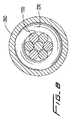
他の実施形態では、一体に撚られたステンレス鋼編組、ケーブルまたはストランドが、コイル(2本巻きワイヤ)の圧縮性を制限する内側コア部材を形成し、かつ前に列挙した大きいスチフネス、強度および他の長所をもたらす。これは図7および図8の実施形態に示されており、この実施形態では、ワイヤ200が、7本の撚られたステンレス鋼ワイヤからなる内側コア220を有する。異なる本数の撚りワイヤを考えることもできる。ワイヤ200の他の要素、例えば外側2本巻きワイヤ230、金属チップ260、チップ280、シュリンクラップ250等は、前述のワイヤ10、100におけるこれらと同じである。The
In other embodiments, integrally twisted stainless steel braids, cables or strands form an inner core member that limits the compressibility of the coil (twisted wire), and has the high stiffness, strength and Bring other advantages. This is illustrated in the embodiment of FIGS. 7 and 8, in which the
本発明の回転式血栓摘出ワイヤ10、100、200は、種々の血栓摘出カテーテルに使用して、血管内の血栓を浸軟化することができる。回転式血栓摘出ワイヤ10(または100または200)は、図1に示すように、カテーテルのフレキシブルシースまたはスリーブC内に収容される。ワイヤとシースCとの相対移動により、ワイヤ10を露出させて、後述のような湾曲形状(波形形状)にすることにより、血管の管腔から血餅等の閉塞物質を除去できる。
ハウジング内には、血栓を血管腔内で小さい粒子に浸軟化および液状化するための、電池により駆動されるモータが収容されている。これは図2に概略的に示されている。ワイヤ10(または100または200)は、モータに連結される。この連結には、直接的連結またはモータが作動されると回転できるようにする介在コンポーネンツを介しての連結が含まれる。ワイヤ10(または100または200)の湾曲領域は、シースC内にあるときは、ワイヤ(それぞれ遠位側領域16、116または216を含む)が実質的に真直すなわち線形の非定置形状をなすように圧縮されている。シースCによるワイヤ10(または100または200)のこの被覆により、導入器シースを介しての挿入および血管内での操作が容易になる。フレキシブルシースCが引出されると、ワイヤが露出されて、ワイヤをその非線形の実質的に波形形状に戻し、血管の管腔内でその長手方向軸線の回りで回転させることができる。The
Housed within the housing is a battery-powered motor to soak and liquefy the thrombus into small particles within the vessel lumen. This is shown schematically in FIG. The wire 10 (or 100 or 200) is connected to a motor. This connection may include a direct connection or via an intervening component that allows rotation when the motor is activated. The curved region of the wire 10 (or 100 or 200) is such that when in the sheath C, the wire (including the
イメージング染料のような流体を、ポートDを通して、ワイヤ10(または100または200)とシースCの内壁との間のスペース内のシースCのルーメン内に注入し、遠位側開口から排出して血管内に流出させることができる。このイメージング染料は、血管内での流体の流れを表示する。また、シースのルーメンは、前述のようにニチノールコア120を冷却する冷たい食塩水を受入れる。
本発明の回転式血栓摘出ワイヤ10、100、200は、特許文献3に開示されたバルーンのような1つ以上のバルーンを備えた血栓摘出カテーテルに使用できる。ワイヤ10、100、200はまた、他の血栓摘出カテーテルにも使用できる。
上記説明は多くの特定構成を含んでいるが、これらの特定構成は本発明の開示範囲を限定するものと解釈すべきではなく、本発明の好ましい実施形態の単なる例示であると解釈すべきである。当業者ならば、特許請求の範囲で定められた開示の範囲および精神内での他の多くの可能な変更を考えることができるであろう。A fluid, such as an imaging dye, is injected through port D into the lumen of sheath C in the space between wire 10 (or 100 or 200) and the inner wall of sheath C and out of the distal opening to drain the blood vessel Can be drained into. This imaging dye displays the fluid flow in the blood vessel. The sheath lumen also receives cold saline to cool the
The
While the above description includes a number of specific configurations, these specific configurations should not be construed as limiting the disclosure scope of the invention, but merely as exemplifications of preferred embodiments of the invention. is there. Those skilled in the art will envision many other possible modifications within the scope and spirit of the disclosure as defined by the claims.
10 血栓摘出ワイヤ
20 コア(内側コア)
30 2本巻きワイヤ(外側ワイヤ)
50 シュリンクラップ
60 金属チップ
80 フレキシブルチップ
C フレキシブルシース(スリーブ)
D ポート10
30 Two-winding wire (outer wire)
50
D port
Claims (13)
Translated fromJapanese該内側コアの少なくとも一部を包囲する多重巻き外側ワイヤとを有し、該多重巻き外側ワイヤは、互いに並べて巻回された少なくとも第一および第二の金属ワイヤを備えかつ遠位領域に波形部分を備え、内側コアは多重巻き外側ワイヤの波形部分内の波形部分を備え、内側コアは多重巻きワイヤの圧縮性を制限し、多重巻きワイヤの近位端は、多重巻きワイヤを回転させて血栓を浸軟化するモータに連結できることを特徴とする血栓または他の閉塞物質を破砕する回転式血栓摘出ワイヤ。An inner core made of flexible material,
A multiple wound outer wire surrounding at least a portion of the inner core, the multiple wound outer wire comprising at least first and second metal wires wound side by side and corrugated portions in the distal region The inner core includes a corrugated portion within the corrugated portion of the multi-winding outer wire, the inner core limits the compressibility of the multi-winding wire, and the proximal end of the multi-winding wire rotates the multi-winding wire to cause thrombus Rotating thrombectomy wire for crushing thrombus or other occluding material, characterized in that it can be connected to a motor that softens.
Applications Claiming Priority (3)
| Application Number | Priority Date | Filing Date | Title |
|---|---|---|---|
| US62862304P | 2004-11-17 | 2004-11-17 | |
| US11/017,112US7819887B2 (en) | 2004-11-17 | 2004-12-20 | Rotational thrombectomy wire |
| PCT/US2005/039856WO2006055265A1 (en) | 2004-11-17 | 2005-11-02 | Rotational thrombectomy wire |
Related Child Applications (1)
| Application Number | Title | Priority Date | Filing Date |
|---|---|---|---|
| JP2012230533ADivisionJP5404892B2 (en) | 2004-11-17 | 2012-10-18 | Rotating thrombectomy wire |
Publications (2)
| Publication Number | Publication Date |
|---|---|
| JP2008520351Atrue JP2008520351A (en) | 2008-06-19 |
| JP2008520351A5 JP2008520351A5 (en) | 2012-12-06 |
Family
ID=35735369
Family Applications (2)
| Application Number | Title | Priority Date | Filing Date |
|---|---|---|---|
| JP2007543096APendingJP2008520351A (en) | 2004-11-17 | 2005-11-02 | Rotating thrombectomy wire |
| JP2012230533AActiveJP5404892B2 (en) | 2004-11-17 | 2012-10-18 | Rotating thrombectomy wire |
Family Applications After (1)
| Application Number | Title | Priority Date | Filing Date |
|---|---|---|---|
| JP2012230533AActiveJP5404892B2 (en) | 2004-11-17 | 2012-10-18 | Rotating thrombectomy wire |
Country Status (7)
| Country | Link |
|---|---|
| US (5) | US7819887B2 (en) |
| EP (1) | EP1811908B1 (en) |
| JP (2) | JP2008520351A (en) |
| AU (1) | AU2005306899B2 (en) |
| CA (1) | CA2588152A1 (en) |
| ES (1) | ES2455515T3 (en) |
| WO (1) | WO2006055265A1 (en) |
Cited By (8)
| Publication number | Priority date | Publication date | Assignee | Title |
|---|---|---|---|---|
| JP2011240146A (en)* | 2010-05-13 | 2011-12-01 | Rex Medical Lp | Rotational thrombectomy wire |
| JP2014500738A (en)* | 2010-10-19 | 2014-01-16 | ディスタル・アクセス・エルエルシー | Apparatus for rotating a medical device, system including the apparatus, and related methods |
| JP2014500760A (en)* | 2010-11-15 | 2014-01-16 | ヴァスキュラー インサイツ エルエルシー | Vascular treatment device |
| US8845621B2 (en) | 2010-10-19 | 2014-09-30 | Distal Access, Llc | Apparatus for rotating medical devices, systems including the apparatus, and associated methods |
| JP2016528989A (en)* | 2013-08-08 | 2016-09-23 | ラピッド メディカル リミテッド | Clot removal device with operable element |
| US10751073B2 (en) | 2008-08-29 | 2020-08-25 | Rapid Medical Ltd | Clot removal device with steerable element |
| US11000307B2 (en) | 2010-10-19 | 2021-05-11 | Minerva Surgical Inc. | Apparatus for rotating medical devices, systems including the apparatus, and associated methods |
| US11446050B2 (en) | 2014-04-28 | 2022-09-20 | Minerva Surgical, Inc. | Tissue resectors with cutting wires, hand operated tissue resecting systems and associated methods |
Families Citing this family (61)
| Publication number | Priority date | Publication date | Assignee | Title |
|---|---|---|---|---|
| WO2001028618A2 (en) | 1999-10-22 | 2001-04-26 | Boston Scientific Corporation | Double balloon thrombectomy catheter |
| US8414543B2 (en) | 1999-10-22 | 2013-04-09 | Rex Medical, L.P. | Rotational thrombectomy wire with blocking device |
| US7819887B2 (en) | 2004-11-17 | 2010-10-26 | Rex Medical, L.P. | Rotational thrombectomy wire |
| CN101547653B (en) | 2006-09-13 | 2012-02-29 | 瓦斯库勒英赛特有限公司 | Vascular Therapy Devices |
| EP3689274A1 (en) | 2007-02-05 | 2020-08-05 | Boston Scientific Limited | Thrombectomy system |
| WO2008098191A2 (en) | 2007-02-08 | 2008-08-14 | C. R. Bard, Inc. | Shape memory medical device and methods of manufacturing |
| JP5114179B2 (en)* | 2007-12-17 | 2013-01-09 | Hoya株式会社 | Bipolar high-frequency treatment instrument for endoscope |
| US9101387B2 (en)* | 2008-06-05 | 2015-08-11 | Cardiovascular Systems, Inc. | Directional rotational atherectomy device with offset spinning abrasive element |
| US8939991B2 (en) | 2008-06-08 | 2015-01-27 | Hotspur Technologies, Inc. | Apparatus and methods for removing obstructive material from body lumens |
| US8945160B2 (en)* | 2008-07-03 | 2015-02-03 | Hotspur Technologies, Inc. | Apparatus and methods for treating obstructions within body lumens |
| CA2729750C (en) | 2008-07-03 | 2017-06-06 | Hotspur Technologies, Inc. | Apparatus and method comprising an expandable balloon or member for treating obstructions within body lumens |
| US9101382B2 (en) | 2009-02-18 | 2015-08-11 | Hotspur Technologies, Inc. | Apparatus and methods for treating obstructions within body lumens |
| CN102186427B (en)* | 2008-09-22 | 2013-12-18 | 浩特斯博尔技术公司 | flow recovery system |
| US9510854B2 (en) | 2008-10-13 | 2016-12-06 | Boston Scientific Scimed, Inc. | Thrombectomy catheter with control box having pressure/vacuum valve for synchronous aspiration and fluid irrigation |
| GB0902339D0 (en)* | 2009-02-12 | 2009-04-01 | St Georges Healthcare Nhs Trus | Percutaneous guidewire |
| US20120109057A1 (en) | 2009-02-18 | 2012-05-03 | Hotspur Technologies, Inc. | Apparatus and methods for treating obstructions within body lumens |
| CN102427844B (en)* | 2009-03-30 | 2014-09-03 | C·R·巴德股份有限公司 | Tip-shapeable guidewire |
| CA2797222C (en)* | 2009-04-23 | 2017-07-25 | Rafael Medina | Instrument for creating a controlled capsulorhexis for cataract surgery |
| US8764779B2 (en) | 2010-05-13 | 2014-07-01 | Rex Medical, L.P. | Rotational thrombectomy wire |
| US9795406B2 (en) | 2010-05-13 | 2017-10-24 | Rex Medical, L.P. | Rotational thrombectomy wire |
| US9023070B2 (en) | 2010-05-13 | 2015-05-05 | Rex Medical, L.P. | Rotational thrombectomy wire coupler |
| EP2517658B1 (en) | 2011-04-27 | 2013-12-04 | Rex Medical, L.P. | Rotational thrombectomy wire |
| CA2776090A1 (en) | 2011-05-16 | 2012-11-16 | Rex Medical, L.P. | Rotational thrombectomy wire coupler |
| US8852220B2 (en) | 2011-09-07 | 2014-10-07 | Abbott Cardiovascular Systems, Inc. | Thrombus penetrating devices, systems, and methods |
| US9126013B2 (en) | 2012-04-27 | 2015-09-08 | Teleflex Medical Incorporated | Catheter with adjustable guidewire exit position |
| US9757536B2 (en)* | 2012-07-17 | 2017-09-12 | Novartis Ag | Soft tip cannula |
| US20140330286A1 (en) | 2013-04-25 | 2014-11-06 | Michael P. Wallace | Methods and Devices for Removing Obstructing Material From the Human Body |
| US10219814B2 (en) | 2013-12-13 | 2019-03-05 | Rex Medical, L.P. | Aspiration system for thrombectomy procedures |
| US9782191B2 (en) | 2014-01-21 | 2017-10-10 | Cook Medical Technologies Llc | Cutting devices and methods |
| US10271869B2 (en) | 2014-03-01 | 2019-04-30 | Rex Medical, L.P. | Atherectomy device |
| US9883877B2 (en) | 2014-05-19 | 2018-02-06 | Walk Vascular, Llc | Systems and methods for removal of blood and thrombotic material |
| US10463389B2 (en) | 2014-12-27 | 2019-11-05 | Rex Medical, L.P. | Atherectomy device |
| US10433868B2 (en) | 2014-12-27 | 2019-10-08 | Rex Medical, L.P. | Artherectomy device |
| US10561440B2 (en) | 2015-09-03 | 2020-02-18 | Vesatek, Llc | Systems and methods for manipulating medical devices |
| US11253292B2 (en) | 2015-09-13 | 2022-02-22 | Rex Medical, L.P. | Atherectomy device |
| CN105232095B (en)* | 2015-09-28 | 2017-11-21 | 宁波胜杰康生物科技有限公司 | A kind of operating theater instruments of multistage adjustable bending |
| US10226263B2 (en) | 2015-12-23 | 2019-03-12 | Incuvate, Llc | Aspiration monitoring system and method |
| US10307175B2 (en) | 2016-03-26 | 2019-06-04 | Rex Medical, L.P | Atherectomy device |
| US10980555B2 (en) | 2016-07-12 | 2021-04-20 | Cardioprolific Inc. | Methods and devices for clots and tissue removal |
| EP3547928B1 (en) | 2016-11-30 | 2024-04-10 | The Regents of The University of California | Microneedle fabrication and device implantation |
| WO2018191227A1 (en) | 2017-04-10 | 2018-10-18 | The Regents Of The University Of Michigan | Hydrodynamic vortex aspiration catheter |
| US11224458B2 (en) | 2017-04-10 | 2022-01-18 | The Regents Of The University Of Michigan | Hydrodynamic vortex aspiration catheter |
| US11690645B2 (en) | 2017-05-03 | 2023-07-04 | Medtronic Vascular, Inc. | Tissue-removing catheter |
| EP4018946A1 (en) | 2017-05-03 | 2022-06-29 | Medtronic Vascular, Inc. | Tissue-removing catheter |
| CN107335126A (en)* | 2017-07-28 | 2017-11-10 | 苏州斯恩维医疗科技有限公司 | One kind intervention conveying composite rope and preparation method thereof |
| US11678905B2 (en) | 2018-07-19 | 2023-06-20 | Walk Vascular, Llc | Systems and methods for removal of blood and thrombotic material |
| CN118697424A (en) | 2018-11-16 | 2024-09-27 | 美敦力瓦斯科尔勒公司 | Tissue Removal Catheter |
| US11819236B2 (en) | 2019-05-17 | 2023-11-21 | Medtronic Vascular, Inc. | Tissue-removing catheter |
| US12274844B2 (en) | 2019-06-24 | 2025-04-15 | Covidien Lp | Thrombus removal device |
| JP2024506374A (en) | 2021-02-15 | 2024-02-13 | ウォーク バスキュラー, エルエルシー | System and method for removing blood and thrombotic material |
| US12274458B2 (en) | 2021-02-15 | 2025-04-15 | Walk Vascular, Llc | Systems and methods for removal of blood and thrombotic material |
| AU2022231082A1 (en) | 2021-03-01 | 2023-09-21 | Endovascular Engineering, Inc. | Aspiration devices for treatment of thrombosis including expandable distal ends and systems and methods thereof |
| US12390236B2 (en) | 2021-03-10 | 2025-08-19 | Covidien Lp | Thrombus removal device |
| US11696793B2 (en) | 2021-03-19 | 2023-07-11 | Crossfire Medical Inc | Vascular ablation |
| US20220330958A1 (en) | 2021-04-19 | 2022-10-20 | Argon Medical Devices, Inc. | Disposable thrombectomy maceration and aspiration system |
| US11980409B2 (en) | 2022-08-08 | 2024-05-14 | Crossfire Medical Inc | Segmental vascular ablation |
| CN115300762A (en)* | 2022-08-30 | 2022-11-08 | 昂泰微精医疗科技(上海)有限公司 | Manufacturing process of superfine multi-strand memory alloy guide wire |
| US12053192B2 (en) | 2022-09-01 | 2024-08-06 | Endovascular Engineering, Inc. | Systems, devices, and methods for aspiration, including expandable structures and rotatable shafts |
| EP4611658A1 (en) | 2022-11-04 | 2025-09-10 | Solvein Inc. | Catheters and related methods for aspiration and controlled delivery of closure agents |
| US20240149020A1 (en) | 2022-11-04 | 2024-05-09 | Controlled Delivery Systems, Inc. | Catheters for the aspiration controlled delivery of closure agents |
| CN116458961B (en)* | 2023-04-14 | 2024-08-13 | 广东博迈医疗科技股份有限公司 | Rotary cutting guide wire of mechanical thrombus removing device and mechanical thrombus removing device |
Citations (2)
| Publication number | Priority date | Publication date | Assignee | Title |
|---|---|---|---|---|
| JP2003299662A (en)* | 2002-04-01 | 2003-10-21 | Rex Medical Lp | Rotational thrombectomy device |
| US6702830B1 (en)* | 1999-09-17 | 2004-03-09 | Bacchus Vascular, Inc. | Mechanical pump for removal of fragmented matter and methods of manufacture and use |
Family Cites Families (135)
| Publication number | Priority date | Publication date | Assignee | Title |
|---|---|---|---|---|
| DE1075903B (en) | 1958-02-04 | 1960-02-18 | Siemens Ag | Safety coupling with permanent magnets |
| US3612058A (en)* | 1968-04-17 | 1971-10-12 | Electro Catheter Corp | Catheter stylets |
| US3749085A (en)* | 1970-06-26 | 1973-07-31 | J Willson | Vascular tissue removing device |
| JPS5620839U (en) | 1979-07-25 | 1981-02-24 | ||
| DE3327779A1 (en)* | 1983-08-02 | 1985-02-14 | B. Braun Melsungen Ag, 3508 Melsungen | MANDRIN FOR TUBULAR CATHETERS AND BODY SEEDS |
| US5067957A (en)* | 1983-10-14 | 1991-11-26 | Raychem Corporation | Method of inserting medical devices incorporating SIM alloy elements |
| US4745919A (en)* | 1985-02-01 | 1988-05-24 | Bundy Mark A | Transluminal lysing system |
| CA1293663C (en) | 1986-01-06 | 1991-12-31 | David Christopher Auth | Transluminal microdissection device |
| US5025799A (en)* | 1987-05-13 | 1991-06-25 | Wilson Bruce C | Steerable memory alloy guide wires |
| US5211183A (en)* | 1987-05-13 | 1993-05-18 | Wilson Bruce C | Steerable memory alloy guide wires |
| US4883460A (en) | 1988-04-25 | 1989-11-28 | Zanetti Paul H | Technique for removing deposits from body vessels |
| US5067489A (en)* | 1988-08-16 | 1991-11-26 | Flexmedics Corporation | Flexible guide with safety tip |
| US4906244A (en) | 1988-10-04 | 1990-03-06 | Cordis Corporation | Balloons for medical devices and fabrication thereof |
| US4984581A (en)* | 1988-10-12 | 1991-01-15 | Flexmedics Corporation | Flexible guide having two-way shape memory alloy |
| US5203772A (en)* | 1989-01-09 | 1993-04-20 | Pilot Cardiovascular Systems, Inc. | Steerable medical device |
| DE3931350A1 (en)* | 1989-09-20 | 1991-03-28 | Kaltenbach Martin | GUIDE SLEEVE FOR IMPORTING CATHETERS |
| US5624392A (en) | 1990-05-11 | 1997-04-29 | Saab; Mark A. | Heat transfer catheters and methods of making and using same |
| US5345945A (en)* | 1990-08-29 | 1994-09-13 | Baxter International Inc. | Dual coil guidewire with radiopaque distal tip |
| US5341818A (en)* | 1992-12-22 | 1994-08-30 | Advanced Cardiovascular Systems, Inc. | Guidewire with superelastic distal portion |
| US5984877A (en)* | 1991-02-05 | 1999-11-16 | Fleischhacker, Jr.; Joseph F. | Guide wire marker technique and coil spring marker technique |
| CA2068584C (en)* | 1991-06-18 | 1997-04-22 | Paul H. Burmeister | Intravascular guide wire and method for manufacture thereof |
| US5213111A (en)* | 1991-07-10 | 1993-05-25 | Cook Incorporated | Composite wire guide construction |
| US5251085A (en)* | 1991-07-17 | 1993-10-05 | Maxtor Corporation | Pivotable arm assembly with reduced thermal distortion |
| US5261877A (en)* | 1991-07-22 | 1993-11-16 | Dow Corning Wright | Method of performing a thrombectomy procedure |
| US5605162A (en)* | 1991-10-15 | 1997-02-25 | Advanced Cardiovascular Systems, Inc. | Method for using a variable stiffness guidewire |
| US5333620A (en)* | 1991-10-30 | 1994-08-02 | C. R. Bard, Inc. | High performance plastic coated medical guidewire |
| US5253653A (en)* | 1991-10-31 | 1993-10-19 | Boston Scientific Corp. | Fluoroscopically viewable guidewire for catheters |
| FR2685190B1 (en) | 1991-12-23 | 1998-08-07 | Jean Marie Lefebvre | ROTARY ATHERECTOMY OR THROMBECTOMY DEVICE WITH CENTRIFUGAL TRANSVERSE DEVELOPMENT. |
| US5251640A (en)* | 1992-03-31 | 1993-10-12 | Cook, Incorporated | Composite wire guide shaft |
| US5217026A (en)* | 1992-04-06 | 1993-06-08 | Kingston Technologies, Inc. | Guidewires with lubricious surface and method of their production |
| WO1993019679A1 (en)* | 1992-04-07 | 1993-10-14 | The Johns Hopkins University | A percutaneous mechanical fragmentation catheter system |
| US5313967A (en)* | 1992-07-24 | 1994-05-24 | Medtronic, Inc. | Helical guidewire |
| DE69325692T2 (en)* | 1992-08-18 | 2000-01-05 | The Spectranetics Corp., Colorado Springs | Guide wire with fiber optics |
| US5299580A (en)* | 1992-10-09 | 1994-04-05 | Scimed Life Systems, Inc. | Guidewire with safety ribbon with substantially axially symmetric flexibility |
| US5360432A (en)* | 1992-10-16 | 1994-11-01 | Shturman Cardiology Systems, Inc. | Abrasive drive shaft device for directional rotational atherectomy |
| US5312427A (en)* | 1992-10-16 | 1994-05-17 | Shturman Cardiology Systems, Inc. | Device and method for directional rotational atherectomy |
| US5540707A (en) | 1992-11-13 | 1996-07-30 | Scimed Life Systems, Inc. | Expandable intravascular occlusion material removal devices and methods of use |
| US5501694A (en) | 1992-11-13 | 1996-03-26 | Scimed Life Systems, Inc. | Expandable intravascular occlusion material removal devices and methods of use |
| US5490859A (en)* | 1992-11-13 | 1996-02-13 | Scimed Life Systems, Inc. | Expandable intravascular occlusion material removal devices and methods of use |
| US5372144A (en) | 1992-12-01 | 1994-12-13 | Scimed Life Systems, Inc. | Navigability improved guidewire construction and method of using same |
| AU7115294A (en)* | 1993-06-24 | 1995-01-24 | Conceptus, Inc. | Guidewire-type device axially moveable by torque or axial force and methods for use thereof |
| US6673025B1 (en)* | 1993-12-01 | 2004-01-06 | Advanced Cardiovascular Systems, Inc. | Polymer coated guidewire |
| CH689170A5 (en)* | 1994-07-11 | 1998-11-13 | Weissenfluh Hawe Neos | Flexible post or not deformable radially and longitudinally avvolgimatrici device for dental use. |
| US5938623A (en)* | 1994-10-28 | 1999-08-17 | Intella Interventional Systems | Guide wire with adjustable stiffness |
| US5584843A (en)* | 1994-12-20 | 1996-12-17 | Boston Scientific Corporation | Shaped wire multi-burr rotational ablation device |
| US5653722A (en)* | 1995-01-03 | 1997-08-05 | Kieturakis; Maciej J. | Anterograde/retrograde spiral dissector and method of use in vein grafting |
| US5797856A (en)* | 1995-01-05 | 1998-08-25 | Cardiometrics, Inc. | Intravascular guide wire and method |
| US5680873A (en)* | 1995-03-02 | 1997-10-28 | Scimed Life Systems, Inc. | Braidless guide catheter |
| US5746701A (en)* | 1995-09-14 | 1998-05-05 | Medtronic, Inc. | Guidewire with non-tapered tip |
| US5569179A (en) | 1995-10-26 | 1996-10-29 | Medelex, Inc. | Acoustic catheter with magnetic drive |
| US6019736A (en)* | 1995-11-06 | 2000-02-01 | Francisco J. Avellanet | Guidewire for catheter |
| US6004279A (en) | 1996-01-16 | 1999-12-21 | Boston Scientific Corporation | Medical guidewire |
| US5836893A (en)* | 1996-03-08 | 1998-11-17 | Scimed Life Systems, Inc. | Intravascular guidewire |
| US5788710A (en) | 1996-04-30 | 1998-08-04 | Boston Scientific Corporation | Calculus removal |
| US5840046A (en)* | 1996-06-21 | 1998-11-24 | Medtronic, Inc. | Guidewire having hydrophilic coating |
| US5833631A (en)* | 1996-06-28 | 1998-11-10 | Target Therapeutics, Inc. | Fiber tip guidewire |
| US5910364A (en)* | 1996-07-10 | 1999-06-08 | Asahi Intecc Co., Ltd. | Guide wire and a method of making the same |
| US5762637A (en)* | 1996-08-27 | 1998-06-09 | Scimed Life Systems, Inc. | Insert molded catheter tip |
| US6217595B1 (en)* | 1996-11-18 | 2001-04-17 | Shturman Cardiology Systems, Inc. | Rotational atherectomy device |
| US5916166A (en)* | 1996-11-19 | 1999-06-29 | Interventional Technologies, Inc. | Medical guidewire with fully hardened core |
| US5882329A (en)* | 1997-02-12 | 1999-03-16 | Prolifix Medical, Inc. | Apparatus and method for removing stenotic material from stents |
| US6251086B1 (en)* | 1999-07-27 | 2001-06-26 | Scimed Life Systems, Inc. | Guide wire with hydrophilically coated tip |
| US5843103A (en)* | 1997-03-06 | 1998-12-01 | Scimed Life Systems, Inc. | Shaped wire rotational atherectomy device |
| US5924998A (en)* | 1997-03-06 | 1999-07-20 | Scimed Life System, Inc. | Guide wire with hydrophilically coated tip |
| US5885227A (en)* | 1997-03-25 | 1999-03-23 | Radius Medical Technologies, Inc. | Flexible guidewire with radiopaque plastic tip |
| CA2204779A1 (en)* | 1997-05-07 | 1998-11-07 | Mark Sunderland | Universal catheter driver/handle |
| JPH1119217A (en) | 1997-07-04 | 1999-01-26 | Olympus Optical Co Ltd | Medical guide wire |
| WO2001028618A2 (en)* | 1999-10-22 | 2001-04-26 | Boston Scientific Corporation | Double balloon thrombectomy catheter |
| US6090118A (en)* | 1998-07-23 | 2000-07-18 | Mcguckin, Jr.; James F. | Rotational thrombectomy apparatus and method with standing wave |
| US6494890B1 (en) | 1997-08-14 | 2002-12-17 | Shturman Cardiology Systems, Inc. | Eccentric rotational atherectomy device |
| US6080117A (en)* | 1997-10-16 | 2000-06-27 | Scimed Life Systems, Inc. | Guide wire extension system |
| CA2309428A1 (en) | 1997-11-07 | 1999-05-20 | Prolifix Medical, Inc. | Methods and systems for treating obstructions in a body lumen |
| US6371928B1 (en)* | 1997-11-07 | 2002-04-16 | Prolifix Medical, Inc. | Guidewire for positioning a catheter against a lumen wall |
| US6106485A (en)* | 1997-11-18 | 2000-08-22 | Advanced Cardivascular Systems, Inc. | Guidewire with shaped intermediate portion |
| US6168570B1 (en)* | 1997-12-05 | 2001-01-02 | Micrus Corporation | Micro-strand cable with enhanced radiopacity |
| US9254143B2 (en) | 1998-02-25 | 2016-02-09 | Revascular Therapeutics, Inc. | Guidewire for crossing occlusions or stenoses having a shapeable distal end |
| US6001112A (en)* | 1998-04-10 | 1999-12-14 | Endicor Medical, Inc. | Rotational atherectomy device |
| US6113614A (en) | 1998-05-05 | 2000-09-05 | Ensurg, Inc. | Medical device for dissolution of tissue within the human body |
| US6306105B1 (en) | 1998-05-14 | 2001-10-23 | Scimed Life Systems, Inc. | High performance coil wire |
| US6083198A (en) | 1998-06-25 | 2000-07-04 | Cardiovention, Inc. | Perfusion catheter providing segmented flow regions and methods of use |
| EP1105181B1 (en)* | 1998-08-19 | 2004-02-04 | Cook Incorporated | Preformed wire guide |
| AU760262B2 (en) | 1998-12-01 | 2003-05-08 | Advanced Cardiovascular Systems Inc. | Guidewire having linear change in stiffness |
| US6165140A (en)* | 1998-12-28 | 2000-12-26 | Micrus Corporation | Composite guidewire |
| US6402706B2 (en) | 1998-12-30 | 2002-06-11 | Advanced Cardiovascular Systems, Inc. | Guide wire with multiple polymer jackets over distal and intermediate core sections |
| US6767353B1 (en)* | 2002-03-01 | 2004-07-27 | Samuel Shiber | Thrombectomy catheter |
| US6482215B1 (en)* | 1999-02-02 | 2002-11-19 | Samuel Shiber | Adjustable vessel cleaner and method |
| US6758851B2 (en)* | 1999-02-02 | 2004-07-06 | Samuel Shiber | Vessel cleaner |
| US6475226B1 (en)* | 1999-02-03 | 2002-11-05 | Scimed Life Systems, Inc. | Percutaneous bypass apparatus and method |
| US6790215B2 (en)* | 1999-04-30 | 2004-09-14 | Edwards Lifesciences Corporation | Method of use for percutaneous material removal device and tip |
| WO2000065987A1 (en)* | 1999-04-30 | 2000-11-09 | Applied Medical Resources Corporation | Guidewire |
| US6620179B2 (en)* | 1999-08-10 | 2003-09-16 | Neurovasx, Inc. | Clot disrupting wire/catheter assembly |
| US6454775B1 (en)* | 1999-12-06 | 2002-09-24 | Bacchus Vascular Inc. | Systems and methods for clot disruption and retrieval |
| US8414543B2 (en) | 1999-10-22 | 2013-04-09 | Rex Medical, L.P. | Rotational thrombectomy wire with blocking device |
| US6217589B1 (en)* | 1999-10-27 | 2001-04-17 | Scimed Life Systems, Inc. | Retrieval device made of precursor alloy cable and method of manufacturing |
| US6458127B1 (en)* | 1999-11-22 | 2002-10-01 | Csaba Truckai | Polymer embolic elements with metallic coatings for occlusion of vascular malformations |
| US6579246B2 (en)* | 1999-12-22 | 2003-06-17 | Sarcos, Lc | Coronary guidewire system |
| US6929633B2 (en)* | 2000-01-25 | 2005-08-16 | Bacchus Vascular, Inc. | Apparatus and methods for clot dissolution |
| US6663613B1 (en) | 2000-01-25 | 2003-12-16 | Bacchus Vascular, Inc. | System and methods for clot dissolution |
| US6579299B2 (en)* | 2000-01-31 | 2003-06-17 | Rex Medical, L.P. | Atherectomy device |
| US6572630B1 (en)* | 2000-01-31 | 2003-06-03 | Rex Medical, L.P | Atherectomy device |
| US20010031981A1 (en)* | 2000-03-31 | 2001-10-18 | Evans Michael A. | Method and device for locating guidewire and treating chronic total occlusions |
| US6599254B2 (en)* | 2000-05-08 | 2003-07-29 | R. Edward Winters | Multi-feature steerable guidewire for vascular systems |
| US6602262B2 (en) | 2000-06-02 | 2003-08-05 | Scimed Life Systems, Inc. | Medical device having linear to rotation control |
| US6824545B2 (en) | 2000-06-29 | 2004-11-30 | Concentric Medical, Inc. | Systems, methods and devices for removing obstructions from a blood vessel |
| US6602207B1 (en)* | 2000-07-19 | 2003-08-05 | Scimed Life Systems, Inc. | Guide wire stiffness transition element |
| ATE287747T1 (en)* | 2000-10-03 | 2005-02-15 | Cook William Europ | GUIDE WIRE |
| US6620114B2 (en)* | 2000-10-05 | 2003-09-16 | Scimed Life Systems, Inc. | Guidewire having a marker segment for length assessment |
| US6669652B2 (en) | 2000-12-21 | 2003-12-30 | Advanced Cardiovascular Systems, Inc. | Guidewire with tapered distal coil |
| US6881194B2 (en)* | 2001-03-21 | 2005-04-19 | Asahi Intec Co., Ltd. | Wire-stranded medical hollow tube, and a medical guide wire |
| JP4051292B2 (en)* | 2001-04-12 | 2008-02-20 | オリンパス株式会社 | Endoscopic treatment tool |
| CA2449433A1 (en)* | 2001-06-20 | 2003-01-03 | Microvention, Inc. | Medical devices having full or partial polymer coatings and their methods of manufacture |
| US6911016B2 (en)* | 2001-08-06 | 2005-06-28 | Scimed Life Systems, Inc. | Guidewire extension system |
| US6918882B2 (en)* | 2001-10-05 | 2005-07-19 | Scimed Life Systems, Inc. | Guidewire with stiffness blending connection |
| JP4028245B2 (en)* | 2002-01-28 | 2007-12-26 | テルモ株式会社 | Guide wire |
| US6926725B2 (en)* | 2002-04-04 | 2005-08-09 | Rex Medical, L.P. | Thrombectomy device with multi-layered rotational wire |
| US8257278B2 (en) | 2002-05-14 | 2012-09-04 | Advanced Cardiovascular Systems, Inc. | Metal composite guide wire |
| JP4138583B2 (en)* | 2002-08-08 | 2008-08-27 | テルモ株式会社 | Guide wire |
| US7309318B2 (en) | 2002-09-18 | 2007-12-18 | Boston Scientific Scimed, Inc. | Flexible composite guidewire for intravascular catheter |
| US7625337B2 (en) | 2003-01-17 | 2009-12-01 | Gore Enterprise Holdings, Inc. | Catheter assembly |
| US7169118B2 (en)* | 2003-02-26 | 2007-01-30 | Scimed Life Systems, Inc. | Elongate medical device with distal cap |
| US7182735B2 (en)* | 2003-02-26 | 2007-02-27 | Scimed Life Systems, Inc. | Elongated intracorporal medical device |
| US20040193073A1 (en)* | 2003-03-31 | 2004-09-30 | Demello Richard M. | Composite guidewire with a linear elastic distal portion |
| US7862575B2 (en)* | 2003-05-21 | 2011-01-04 | Yale University | Vascular ablation apparatus and method |
| US7540845B2 (en)* | 2003-09-05 | 2009-06-02 | Boston Scientific Scimed, Inc | Medical device coil |
| US7824345B2 (en)* | 2003-12-22 | 2010-11-02 | Boston Scientific Scimed, Inc. | Medical device with push force limiter |
| US7666202B2 (en) | 2004-01-07 | 2010-02-23 | Cardiovascular Systems, Inc. | Orbital atherectomy device guide wire design |
| US7819887B2 (en)* | 2004-11-17 | 2010-10-26 | Rex Medical, L.P. | Rotational thrombectomy wire |
| JP4834367B2 (en)* | 2005-09-29 | 2011-12-14 | 日本ライフライン株式会社 | Guide wire and manufacturing method thereof |
| WO2008057554A1 (en) | 2006-11-08 | 2008-05-15 | Cook Incorporated | Thrombus removal device |
| US8439937B2 (en) | 2007-06-25 | 2013-05-14 | Cardiovascular Systems, Inc. | System, apparatus and method for opening an occluded lesion |
| US8361095B2 (en) | 2009-02-17 | 2013-01-29 | Cook Medical Technologies Llc | Loop thrombectomy device |
| US20110077673A1 (en) | 2009-09-29 | 2011-03-31 | Cardiovascular Systems, Inc. | Rotational atherectomy device with frictional clutch having magnetic normal force |
| US8663259B2 (en) | 2010-05-13 | 2014-03-04 | Rex Medical L.P. | Rotational thrombectomy wire |
| US9023070B2 (en) | 2010-05-13 | 2015-05-05 | Rex Medical, L.P. | Rotational thrombectomy wire coupler |
| US8764779B2 (en) | 2010-05-13 | 2014-07-01 | Rex Medical, L.P. | Rotational thrombectomy wire |
- 2004
- 2004-12-20USUS11/017,112patent/US7819887B2/ennot_activeExpired - Lifetime
- 2005
- 2005-11-02ESES05816969.9Tpatent/ES2455515T3/enactiveActive
- 2005-11-02AUAU2005306899Apatent/AU2005306899B2/ennot_activeCeased
- 2005-11-02CACA002588152Apatent/CA2588152A1/ennot_activeAbandoned
- 2005-11-02JPJP2007543096Apatent/JP2008520351A/enactivePending
- 2005-11-02WOPCT/US2005/039856patent/WO2006055265A1/enactiveApplication Filing
- 2005-11-02EPEP05816969.9Apatent/EP1811908B1/enactiveActive
- 2010
- 2010-08-11USUS12/854,378patent/US8062317B2/ennot_activeExpired - Lifetime
- 2011
- 2011-10-19USUS13/276,398patent/US8465511B2/ennot_activeExpired - Fee Related
- 2012
- 2012-10-18JPJP2012230533Apatent/JP5404892B2/enactiveActive
- 2013
- 2013-06-02USUS13/907,953patent/US9474543B2/ennot_activeExpired - Lifetime
- 2016
- 2016-09-20USUS15/270,606patent/US10117671B2/ennot_activeExpired - Lifetime
Patent Citations (2)
| Publication number | Priority date | Publication date | Assignee | Title |
|---|---|---|---|---|
| US6702830B1 (en)* | 1999-09-17 | 2004-03-09 | Bacchus Vascular, Inc. | Mechanical pump for removal of fragmented matter and methods of manufacture and use |
| JP2003299662A (en)* | 2002-04-01 | 2003-10-21 | Rex Medical Lp | Rotational thrombectomy device |
Cited By (12)
| Publication number | Priority date | Publication date | Assignee | Title |
|---|---|---|---|---|
| US10751073B2 (en) | 2008-08-29 | 2020-08-25 | Rapid Medical Ltd | Clot removal device with steerable element |
| JP2011240146A (en)* | 2010-05-13 | 2011-12-01 | Rex Medical Lp | Rotational thrombectomy wire |
| JP2014500738A (en)* | 2010-10-19 | 2014-01-16 | ディスタル・アクセス・エルエルシー | Apparatus for rotating a medical device, system including the apparatus, and related methods |
| US8845621B2 (en) | 2010-10-19 | 2014-09-30 | Distal Access, Llc | Apparatus for rotating medical devices, systems including the apparatus, and associated methods |
| US9107691B2 (en) | 2010-10-19 | 2015-08-18 | Distal Access, Llc | Apparatus for rotating medical devices, systems including the apparatus, and associated methods |
| US11000307B2 (en) | 2010-10-19 | 2021-05-11 | Minerva Surgical Inc. | Apparatus for rotating medical devices, systems including the apparatus, and associated methods |
| US12171456B2 (en) | 2010-10-19 | 2024-12-24 | Minerva Surgical, Inc. | Apparatus for rotating medical devices, systems including the apparatus, and associated methods |
| JP2014500760A (en)* | 2010-11-15 | 2014-01-16 | ヴァスキュラー インサイツ エルエルシー | Vascular treatment device |
| US9585667B2 (en) | 2010-11-15 | 2017-03-07 | Vascular Insights Llc | Sclerotherapy catheter with lumen having wire rotated by motor and simultaneous withdrawal from vein |
| US11241250B2 (en) | 2010-11-15 | 2022-02-08 | Merit Medical Systems, Inc. | Vascular treatment devices and methods |
| JP2016528989A (en)* | 2013-08-08 | 2016-09-23 | ラピッド メディカル リミテッド | Clot removal device with operable element |
| US11446050B2 (en) | 2014-04-28 | 2022-09-20 | Minerva Surgical, Inc. | Tissue resectors with cutting wires, hand operated tissue resecting systems and associated methods |
Also Published As
| Publication number | Publication date |
|---|---|
| EP1811908A1 (en) | 2007-08-01 |
| US20060106407A1 (en) | 2006-05-18 |
| AU2005306899A1 (en) | 2006-05-26 |
| JP2013017834A (en) | 2013-01-31 |
| EP1811908B1 (en) | 2014-01-08 |
| US20120035634A1 (en) | 2012-02-09 |
| AU2005306899B2 (en) | 2011-05-26 |
| US20100305592A1 (en) | 2010-12-02 |
| US8465511B2 (en) | 2013-06-18 |
| US20130267844A1 (en) | 2013-10-10 |
| US10117671B2 (en) | 2018-11-06 |
| US7819887B2 (en) | 2010-10-26 |
| US8062317B2 (en) | 2011-11-22 |
| JP5404892B2 (en) | 2014-02-05 |
| US9474543B2 (en) | 2016-10-25 |
| US20170007290A1 (en) | 2017-01-12 |
| WO2006055265A1 (en) | 2006-05-26 |
| CA2588152A1 (en) | 2006-05-26 |
| ES2455515T3 (en) | 2014-04-15 |
Similar Documents
| Publication | Publication Date | Title |
|---|---|---|
| JP5404892B2 (en) | Rotating thrombectomy wire | |
| JP4418164B2 (en) | Rotating thrombectomy device | |
| US10064645B2 (en) | Rotational thrombectomy wire | |
| US8414543B2 (en) | Rotational thrombectomy wire with blocking device | |
| US6926725B2 (en) | Thrombectomy device with multi-layered rotational wire | |
| US9700346B2 (en) | Rotational thrombectomy wire | |
| EP2700368B1 (en) | Rotational thrombectomy wire | |
| Vesely | Techniques for using mechanical thrombectomy devices to treat thrombosed hemodialysis grafts |
Legal Events
| Date | Code | Title | Description |
|---|---|---|---|
| A621 | Written request for application examination | Free format text:JAPANESE INTERMEDIATE CODE: A621 Effective date:20081029 | |
| A977 | Report on retrieval | Free format text:JAPANESE INTERMEDIATE CODE: A971007 Effective date:20110526 | |
| A131 | Notification of reasons for refusal | Free format text:JAPANESE INTERMEDIATE CODE: A131 Effective date:20110530 | |
| A601 | Written request for extension of time | Free format text:JAPANESE INTERMEDIATE CODE: A601 Effective date:20110830 | |
| A602 | Written permission of extension of time | Free format text:JAPANESE INTERMEDIATE CODE: A602 Effective date:20110906 | |
| A521 | Request for written amendment filed | Free format text:JAPANESE INTERMEDIATE CODE: A523 Effective date:20111130 | |
| A131 | Notification of reasons for refusal | Free format text:JAPANESE INTERMEDIATE CODE: A131 Effective date:20120528 | |
| A601 | Written request for extension of time | Free format text:JAPANESE INTERMEDIATE CODE: A601 Effective date:20120828 | |
| A602 | Written permission of extension of time | Free format text:JAPANESE INTERMEDIATE CODE: A602 Effective date:20120904 | |
| A524 | Written submission of copy of amendment under article 19 pct | Free format text:JAPANESE INTERMEDIATE CODE: A524 Effective date:20121018 | |
| A02 | Decision of refusal | Free format text:JAPANESE INTERMEDIATE CODE: A02 Effective date:20130401 |