JP2008520290A - Ventilation catheter and airway management system to remove secretions - Google Patents
Ventilation catheter and airway management system to remove secretionsDownload PDFInfo
- Publication number
- JP2008520290A JP2008520290AJP2007541610AJP2007541610AJP2008520290AJP 2008520290 AJP2008520290 AJP 2008520290AJP 2007541610 AJP2007541610 AJP 2007541610AJP 2007541610 AJP2007541610 AJP 2007541610AJP 2008520290 AJP2008520290 AJP 2008520290A
- Authority
- JP
- Japan
- Prior art keywords
- lumen
- ventilation catheter
- patient
- fluid
- ventilation
- Prior art date
- Legal status (The legal status is an assumption and is not a legal conclusion. Google has not performed a legal analysis and makes no representation as to the accuracy of the status listed.)
- Pending
Links
- BWOUGSIOJMUVHK-UHFFFAOYSA-NCC1[IH]CCC1Chemical compoundCC1[IH]CCC1BWOUGSIOJMUVHK-UHFFFAOYSA-N0.000description1
Images


Classifications
- A—HUMAN NECESSITIES
- A61—MEDICAL OR VETERINARY SCIENCE; HYGIENE
- A61M—DEVICES FOR INTRODUCING MEDIA INTO, OR ONTO, THE BODY; DEVICES FOR TRANSDUCING BODY MEDIA OR FOR TAKING MEDIA FROM THE BODY; DEVICES FOR PRODUCING OR ENDING SLEEP OR STUPOR
- A61M16/00—Devices for influencing the respiratory system of patients by gas treatment, e.g. ventilators; Tracheal tubes
- A61M16/04—Tracheal tubes
- A61M16/0402—Special features for tracheal tubes not otherwise provided for
- A61M16/042—Special features for tracheal tubes not otherwise provided for with separate conduits for in-and expiration gas, e.g. for limited dead volume
- A—HUMAN NECESSITIES
- A61—MEDICAL OR VETERINARY SCIENCE; HYGIENE
- A61M—DEVICES FOR INTRODUCING MEDIA INTO, OR ONTO, THE BODY; DEVICES FOR TRANSDUCING BODY MEDIA OR FOR TAKING MEDIA FROM THE BODY; DEVICES FOR PRODUCING OR ENDING SLEEP OR STUPOR
- A61M16/00—Devices for influencing the respiratory system of patients by gas treatment, e.g. ventilators; Tracheal tubes
- A61M16/04—Tracheal tubes
- A61M16/0434—Cuffs
- A61M16/0445—Special cuff forms, e.g. undulated
- A—HUMAN NECESSITIES
- A61—MEDICAL OR VETERINARY SCIENCE; HYGIENE
- A61M—DEVICES FOR INTRODUCING MEDIA INTO, OR ONTO, THE BODY; DEVICES FOR TRANSDUCING BODY MEDIA OR FOR TAKING MEDIA FROM THE BODY; DEVICES FOR PRODUCING OR ENDING SLEEP OR STUPOR
- A61M16/00—Devices for influencing the respiratory system of patients by gas treatment, e.g. ventilators; Tracheal tubes
- A61M16/04—Tracheal tubes
- A61M16/0463—Tracheal tubes combined with suction tubes, catheters or the like; Outside connections
- A—HUMAN NECESSITIES
- A61—MEDICAL OR VETERINARY SCIENCE; HYGIENE
- A61M—DEVICES FOR INTRODUCING MEDIA INTO, OR ONTO, THE BODY; DEVICES FOR TRANSDUCING BODY MEDIA OR FOR TAKING MEDIA FROM THE BODY; DEVICES FOR PRODUCING OR ENDING SLEEP OR STUPOR
- A61M16/00—Devices for influencing the respiratory system of patients by gas treatment, e.g. ventilators; Tracheal tubes
- A61M16/04—Tracheal tubes
- A61M16/0486—Multi-lumen tracheal tubes
- A—HUMAN NECESSITIES
- A61—MEDICAL OR VETERINARY SCIENCE; HYGIENE
- A61M—DEVICES FOR INTRODUCING MEDIA INTO, OR ONTO, THE BODY; DEVICES FOR TRANSDUCING BODY MEDIA OR FOR TAKING MEDIA FROM THE BODY; DEVICES FOR PRODUCING OR ENDING SLEEP OR STUPOR
- A61M16/00—Devices for influencing the respiratory system of patients by gas treatment, e.g. ventilators; Tracheal tubes
- A61M16/04—Tracheal tubes
- A61M16/0488—Mouthpieces; Means for guiding, securing or introducing the tubes
- A61M16/049—Mouthpieces
- A61M16/0493—Mouthpieces with means for protecting the tube from damage caused by the patient's teeth, e.g. bite block
- A—HUMAN NECESSITIES
- A61—MEDICAL OR VETERINARY SCIENCE; HYGIENE
- A61M—DEVICES FOR INTRODUCING MEDIA INTO, OR ONTO, THE BODY; DEVICES FOR TRANSDUCING BODY MEDIA OR FOR TAKING MEDIA FROM THE BODY; DEVICES FOR PRODUCING OR ENDING SLEEP OR STUPOR
- A61M16/00—Devices for influencing the respiratory system of patients by gas treatment, e.g. ventilators; Tracheal tubes
- A61M16/04—Tracheal tubes
- A61M16/0475—Tracheal tubes having openings in the tube
- A61M16/0477—Tracheal tubes having openings in the tube with incorporated means for delivering or removing fluids
- A61M16/0484—Tracheal tubes having openings in the tube with incorporated means for delivering or removing fluids at the distal end
- A—HUMAN NECESSITIES
- A61—MEDICAL OR VETERINARY SCIENCE; HYGIENE
- A61M—DEVICES FOR INTRODUCING MEDIA INTO, OR ONTO, THE BODY; DEVICES FOR TRANSDUCING BODY MEDIA OR FOR TAKING MEDIA FROM THE BODY; DEVICES FOR PRODUCING OR ENDING SLEEP OR STUPOR
- A61M16/00—Devices for influencing the respiratory system of patients by gas treatment, e.g. ventilators; Tracheal tubes
- A61M16/10—Preparation of respiratory gases or vapours
- A61M16/105—Filters
- A61M16/1055—Filters bacterial
- A—HUMAN NECESSITIES
- A61—MEDICAL OR VETERINARY SCIENCE; HYGIENE
- A61M—DEVICES FOR INTRODUCING MEDIA INTO, OR ONTO, THE BODY; DEVICES FOR TRANSDUCING BODY MEDIA OR FOR TAKING MEDIA FROM THE BODY; DEVICES FOR PRODUCING OR ENDING SLEEP OR STUPOR
- A61M16/00—Devices for influencing the respiratory system of patients by gas treatment, e.g. ventilators; Tracheal tubes
- A61M16/10—Preparation of respiratory gases or vapours
- A61M16/105—Filters
- A61M16/106—Filters in a path
- A61M16/1065—Filters in a path in the expiratory path
- A—HUMAN NECESSITIES
- A61—MEDICAL OR VETERINARY SCIENCE; HYGIENE
- A61M—DEVICES FOR INTRODUCING MEDIA INTO, OR ONTO, THE BODY; DEVICES FOR TRANSDUCING BODY MEDIA OR FOR TAKING MEDIA FROM THE BODY; DEVICES FOR PRODUCING OR ENDING SLEEP OR STUPOR
- A61M25/00—Catheters; Hollow probes
- A61M25/10—Balloon catheters
- A61M2025/1043—Balloon catheters with special features or adapted for special applications
- A61M2025/1052—Balloon catheters with special features or adapted for special applications for temporarily occluding a vessel for isolating a sector
Landscapes
- Health & Medical Sciences (AREA)
- Pulmonology (AREA)
- Life Sciences & Earth Sciences (AREA)
- Animal Behavior & Ethology (AREA)
- Anesthesiology (AREA)
- Biomedical Technology (AREA)
- Heart & Thoracic Surgery (AREA)
- Hematology (AREA)
- Emergency Medicine (AREA)
- Engineering & Computer Science (AREA)
- General Health & Medical Sciences (AREA)
- Public Health (AREA)
- Veterinary Medicine (AREA)
- Otolaryngology (AREA)
- Media Introduction/Drainage Providing Device (AREA)
- External Artificial Organs (AREA)
Abstract
Translated fromJapaneseDescription
Translated fromJapanese本出願は2004年11月19日に出願された米国仮出願No. 60/629,074の利益を主張する。 This application claims the benefit of US Provisional Application No. 60 / 629,074, filed Nov. 19, 2004.
本発明は、気管チューブの名で一般に知られ、気管内の換気などに使用される換気用カテーテルに関する。 The present invention relates to a ventilation catheter commonly known by the name of a tracheal tube and used for ventilation in the trachea.
従来の気道確保の作業には、定量の吸気用流体を送る機械的な換気装置を用いた換気処置を伴うが、この吸気用流体は、エアガスないしは酸素ガスの混合体からなり、ときには水蒸気も加えられて患者の肺に一定周期で送られる。換気装置は、吸気用流体を高圧力下の給気システムを通して瞬時に患者の肺へ供給する動作と、給気システム内の圧力を瞬時に下げ、使用済みの吸気用流体は患者の肺から排出する動作を繰り返す。この換気装置による新たな吸気用流体の供給と、使用済み吸気用流体の排出との繰り返し動作によって、患者に自発呼吸がない間、患者の体内に適切な酸素を確保する。 The conventional airway maintenance work involves a ventilation procedure using a mechanical ventilator that sends a fixed amount of intake fluid. This intake fluid consists of a mixture of air gas or oxygen gas, sometimes with the addition of water vapor. And sent to the patient's lungs at regular intervals. The ventilator instantaneously supplies the inspiratory fluid to the patient's lungs through the high pressure air supply system, and instantaneously lowers the pressure in the air supply system, draining the used inspiratory fluid from the patient's lungs Repeat the operation. By repetitive operations of supplying a new inspiratory fluid by the ventilator and discharging the used inspiratory fluid, appropriate oxygen is secured in the patient's body while the patient is not spontaneously breathing.
近年の気道確保システムは、患者の肺へ酸素含有流体を連続して送ると同時に使用済みの流体を肺から排出させる非循環型の処置により、患者へ酸素を供給することも可能になっている。かかるシステム類型の例は米国特許第5706830号に開示されている。 Recent airway management systems can also deliver oxygen to the patient through a non-circulating procedure that continuously delivers oxygen-containing fluid to the patient's lungs while simultaneously draining the used fluid from the lungs. . An example of such a system type is disclosed in US Pat. No. 5,706,830.
換気用カテーテルは、しばしば気管用チューブと呼ばれ、患者の肺へ吸気用流体を供給する気道確保システムにおいて、従来から、また近年の手法でも使用されている。気管用チューブを歴史的にみると、ルーメンと呼ばれる中空内管からなり、遠位端部に開口を有する1本のチューブであった。前記遠位端部は患者の口から気管へと挿入され、声帯を越えた位置に配置される。気管用チューブの他端部は、換気装置と動作可能に接続されている。このようにして、吸気用流体は気管用チューブを通って肺へ直接供給され、同じ気管用チューブを通って肺から排出される。 Ventilation catheters, often referred to as tracheal tubes, have been used in conventional and recent approaches in airway management systems that supply inspiratory fluid to a patient's lungs. Historically, the tracheal tube was a single tube consisting of a hollow inner tube called a lumen and having an opening at the distal end. The distal end is inserted from the patient's mouth into the trachea and is positioned beyond the vocal cords. The other end of the tracheal tube is operably connected to a ventilator. In this way, inspiratory fluid is supplied directly to the lungs through the tracheal tube and is exhausted from the lungs through the same tracheal tube.
患者の気管内への挿入や位置決めを行いやすいよう、気管用チューブの断面はかなり小さくてはならない。もっとも、酸素含有流体を十分に供給できる大きさを有している必要がある。 The cross section of the tracheal tube should be fairly small to facilitate insertion and positioning in the patient's trachea. However, it is necessary to have a size that can sufficiently supply the oxygen-containing fluid.
今日までの気管用チューブの使用や操作に関する改良は、2つの問題点を解決することに重点が置かれていた。第1は、気管内にある気管用チューブの安全性及び空気漏れを改善することである。第2は、肺もしくは肺胞を空気的に隔絶する気管用チューブの機能を向上させることである。 Improvements to the use and operation of tracheal tubes to date have focused on solving two problems. The first is to improve the safety and air leakage of the tracheal tube within the trachea. The second is to improve the function of the tracheal tube that pneumatically isolates the lungs or alveoli.
第1の問題に関しては、解決策の1つとして、気管用チューブの遠位端部付近に膨張式カフを取り付ける方法がとられてきた。当該カフは、チューブを挿入する時はしぼんでおり、気管内の適当な位置までチューブが挿入されたら膨張し、チューブを定位置に保ちつつ密封状態を形成する。この類のカフの構造は、ニクラソンその他の米国特許第6443156号における図1Aおよび図1Bに示されている。 Regarding the first problem, one solution has been to attach an inflatable cuff near the distal end of the tracheal tube. The cuff is deflated when the tube is inserted, and expands when the tube is inserted to an appropriate position in the trachea, forming a sealed state while keeping the tube in place. The structure of this type of cuff is shown in FIGS. 1A and 1B in US Pat. No. 6,443,156 to Nicrason et al.
これらカフは、密封性を確保し、患者の気道が胃液や咽頭液により感染される可能性を低くするが、他方で患者の肺分泌物や肺液の出入りも塞いでしまう。患者は一般的に、一日で200〜400cm3の肺分泌物や肺液を排出する。この数値は患者が肺の感染症や特定の心臓病を患っていると劇的に大きくなる。These cuffs ensure sealing and reduce the likelihood that the patient's airways will be infected by gastric or pharyngeal fluid, but also block the patient's entry and exit of lung secretions. Patients typically drain 200-400 cm3 of pulmonary secretions and fluids per day. This figure increases dramatically when the patient has a lung infection or certain heart disease.
機械的換気の最中に生じる肺の分泌物や肺液の増加に対処するために、患者の肺から周期的に吸引を行い、副次的感染を防ぐ抗生物質を使用した処置が通常とられる。かかる周期的な吸引は、吸引の度に患者の肺に損傷を与えたり気道を感染させる危険を伴う。 Treatment with antibiotics that are periodically aspirated from the patient's lungs to prevent secondary infections is usually taken to deal with the increase in lung secretions and fluids that occur during mechanical ventilation . Such periodic suction involves the risk of damaging the patient's lungs and infecting the airways with each suction.
第2の問題に関しある発明者は、気管用チューブの中に複数の独立したルーメンを設けることで肺や肺胞を隔離することを試みた。各チューブがそれぞれ膨張式カフを備えており、肺や肺胞を隔離することができる。しかしながら、各チューブは、吸気用流体を肺へ供給し、使用済みの吸気用流体を排出する点で、単体のルーメンチューブと動作に変わりはない。かかる構造を有するチューブは、肺の分泌物や肺液を増加させることがあるため、従来の分泌物の吸引や抗生物質による治療の措置をとらなくてはならなかった。さらに、気管用チューブの断面がある程度大きくなるため、子供や幼児など気道が小さい場合には有用性が薄れてしまう。 An inventor regarding the second problem attempted to isolate lungs and alveoli by providing a plurality of independent lumens in the tracheal tube. Each tube has an inflatable cuff to isolate the lungs and alveoli. However, each tube is the same as a single lumen tube in terms of supplying inspiratory fluid to the lungs and discharging used inspiratory fluid. A tube having such a structure may increase pulmonary secretions and pulmonary fluids, and therefore, it has been necessary to take measures for conventional secretion aspiration and treatment with antibiotics. Furthermore, since the cross section of the tracheal tube becomes large to some extent, the usefulness is diminished when the airway is small, such as a child or an infant.
このように、従来の換気用カテーテルは利点があるものの、患者の肺へ挿入が容易で、補助的な吸引装置などを使用しなくとも肺の分泌物や肺液を容易に除去できる小型の気管用チューブが必要とされている。ここに記した利点に加え、本発明は、これらの課題を解決するものである。 As described above, although the conventional ventilation catheter has advantages, it is easy to insert into the patient's lung and can easily remove lung secretions and pulmonary fluid without using an auxiliary suction device. A tube is needed. In addition to the advantages described herein, the present invention solves these problems.
開示する一実施例である肺分泌物を除去する換気用カテーテルは、2本のルーメンからなる二重ルーメン部を有し、各ルーメンは気道確保システムに動作可能に接続され、吸気用流体が2本のルーメンのうちの1本を通って前記換気用カテーテルの遠位端へ送られ、使用された吸気用流体、肺分泌物および肺液がもう1本のルーメンを通って排出される。 A disclosed embodiment of a ventilating catheter for removing pulmonary secretions has a double lumen portion consisting of two lumens, each lumen being operatively connected to an airway securing system and two inspiratory fluids. One of the lumens is routed to the distal end of the ventilation catheter and used inspiratory fluid, pulmonary secretions and lung fluid are drained through the other lumen.
使用済み吸気用流体が通る経路には、肺分泌物を除去する分泌物回収システムを設け、システムの動作や安全性を向上させることが好ましい。さらに、使用済み吸気用流体を外部へ放出するのでなくシステム内に留保することで、SARSなどに感染している患者から空中感染物質が放出される可能性を最小限におさえることができる。 It is preferable to provide a secretion collection system for removing pulmonary secretions in the path through which the used inspiratory fluid passes to improve the operation and safety of the system. Furthermore, the possibility that airborne infectious substances are released from patients infected with SARS or the like can be minimized by retaining the used inspiratory fluid in the system rather than releasing it outside.
また、改良カフを使用してもよい。前記改良カフは、換気用カテーテルの遠位端に設置され、気管内を密封する。カフの一側面には、換気用カテーテルの動作中に患者の肺から少量の空気を逃がすチャネルが設けられている。この空気漏出チャネルにより、換気用カテーテルの動作を中断することなく、肺分泌物の除去を促進することができる。 An improved cuff may also be used. The modified cuff is placed at the distal end of the ventilation catheter and seals the trachea. One side of the cuff is provided with a channel that allows a small amount of air to escape from the patient's lungs during operation of the ventilation catheter. This air leakage channel can facilitate removal of pulmonary secretions without interrupting the operation of the ventilation catheter.
本発明におけるその他の利点や特徴は、以下の詳細な説明及び図面から明らかになるであろう。 Other advantages and features of the present invention will become apparent from the following detailed description and drawings.
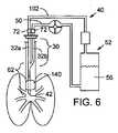
肺分泌物を除去する換気用カテーテル20およびこれに関連した気道確保装置22が図1ないし13に開示されている。一般的に、換気用カテーテル20は気管用チューブとも呼ばれ、換気を行うために患者26の気管24内にまで差し込まれる。この換気用カテーテル20は、二重ルーメン部30を有している。前記二重ルーメン部30の各ルーメン32a、32bは、気道確保装置40(図6ないし8)に動作可能なように接続されており、吸気用流体(空気ないし酸素含有流体で水蒸気を含むこともある)は、2本のルーメン32a、32b(ここでは32aとする)のうちの1本(ここでは32aとする)を通って換気用カテーテル20の遠位端部42まで送られ、使用された吸気用流体、肺分泌物および肺液は、もう1本のルーメン32a、32b(ここでは32bとする)を通って患者から除去される。 A
独立したルーメン32a、32bをそれぞれ通し、吸気用流体の流入と流出を分離することにより、新しく入ってくる吸気用流体を、使用された吸気用流体や肺分泌物による汚染から防ぐことができる。使用済み吸気用流体の排出経路50(図6ないし8)は、該排出経路50から運ばれてくる分泌物を回収する分泌物回収システム52を備えていることが好ましく、これによりシステムの稼働や安全性を向上させる。また、使用済み吸気用流体を外部に排出するのでなく、装置内に留保させることにより、SARS等の感染者から空中感染物質が放出されるのを最小限に抑えることができる。 By separating the inflow and outflow of the inspiratory fluid through the
本明細書では、これらの基本的特徴を備えたいくつかの実施例が開示されている。構成要素などの不要な繰り返しをさけるため、番号を使用する。 Several embodiments with these basic features are disclosed herein. Use numbers to avoid unnecessary repetition of components.
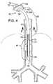
図1を参照するに、第1実施例である換気カテーテル20a図示されている。本実施例において、二重ルーメン部30は、患者の声帯61の川上である咽頭領域ないしは咽頭領域の手前に位置している。二重ルーメン部30における各ルーメン32a、32bは、空気圧によって互いに合流し単一ルーメン部62となり、換気用カテーテル20aの遠位端部42まで伸延している。単一ルーメン部62は患者の気管内領域70へ突出している。これにより、二重ルーメン部30を用いた分泌物除去の利点を活かしつつ、直径の小さな単一ルーメン部62を声帯を越えて気管にまで伸延させることが可能となっている。二重ルーメン部30を咽頭部より手前に位置させることにより、換気効率を向上させ、不要なスペースを省き、分泌物を除去し、そして従来より使われている直径の小さな気管カテーテルを使用することが可能となっている。 Referring to FIG. 1, a
二重ルーメン部30を構成する各ルーメン32a、32bは従来周知のアダプター72に接続され、従来周知の換気システム40(図6)のコネクタに着脱可能に固定される近位端部80を有することが好ましい。ルーメン32aはコネクタを介して、換気システム100(図6)の導管102に接続されている。ルーメン32bは換気システム100の使用済み吸気用流体の排出経路に接続されている。本システム100は、予め設定された流速で吸気用流体を送るよう制御することができる。吸気用流体は、約20mmHgの圧力でルーメン32aの近位端部へ選択された周期で送られる。その後、装置内の気圧は約6mmHgにまで落とされ、換気周期における呼気段階となる。これにより、肺分泌物や肺液をルーメン32bから排出させる流動が生じる。 Each
さらに換気システム100は、換気システム40の吸気段階、呼気段階のどちらにおいても、二重ルーメン部30のうちの1本であるルーメン32aを通して吸気用流体が供給されると同時に、ルーメン部30のもう1本のルーメン32bを通して使用済み吸気用流体や分泌物が患者から排出されるよう設計されることが好ましい。 Furthermore, the ventilation system 100 is supplied with the inspiratory fluid through the
換気用カテーテル20aの先端部110は、カテーテルを挿管する際に単一ルーメン部を通過させやすいよう斜めに切られ、軟らかくなっている。先端部は、気道を塞ぐことがある後屈に耐えるよう設計されることが望ましい。 The
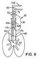
換気用カテーテルの二重ルーメン部および単一ルーメン部は、ともに医療上認可されている軟らかくて透明なエラストマーで作成されることが好ましい。必要であれば、図9に示すように、フラップ弁のようなチェック弁170を二重ルーメン部の一方ないしは双方に取り付け、ルーメン内での逆流を防ぐことができる。 Both the double lumen portion and the single lumen portion of the ventilation catheter are preferably made from a soft, transparent elastomer that is medically approved. If necessary, as shown in FIG. 9, a
膨張式カフ140は換気用カテーテルの遠位端部42の付近に位置させることが好ましい。膨張式カフ140は、充分な不透水性を示すプラスチックなどの薄膜で形成することが好ましい。カフの端部は、単一ルーメン部62の外表面に接着されている。カフ140は、米国特許第6443156号の図1Aおよび図1Bに示される周知の方法、すなわち換気用カテーテル20a内にカフ140から補助空気ポンプへ延びるカフ膨張管を備えた装置によって膨張される。 The
換気用カテーテル20aは、図3に示されるようにカフ140がしぼんだ状態のまま患者の気管内に挿入される。そしてその後、カフ140が膨張する。カフ140はひとたび膨張すると、図1及び図2に示されるように、気管の断面形状を囲む形状に拡大し、患者の肺を空気圧によりふさぐことになる。 The
耐久性があり、咬傷に強い咬合阻止具150が、図1に示すように換気用カテーテルの二重ルーメン部に取り付けられていることが好ましい。二重ルーメン部のルーメン32a、32bは、咬合阻止具150の穴に通されている。さらに、咬合阻止具を二重ルーメン部に沿って摺らせることにより患者の歯や唇の位置に合わせられるよう、咬合阻止具を二重ルーメン部30に摺動可能に取り付けることが好ましい。咬合組織150は、二重ルーメン部30と並行して1つ以上の貫通孔を設けることが好ましい。これら孔は必要に応じて、気管内用のブロッキングカテーテルやファイバスコープ用に使用することができる。換気孔151も必要に応じて設けられる。 It is preferable that the
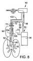
換気システム40(図6)は、図7及び8に示されるように流出回路に分泌物回収装置52を備えていることが好ましい。該分泌物回収装置52は、分泌物回収チャンバ56を有し、該チャンバは、使用済み吸気用流体の排出路50と分岐点58を介して空気圧で通じている。分泌物が使用済み吸気用流体の排出路50内の分岐点58を通過すると、分泌物は重力で自然に、または補助ポンプ59の力を借りて回収チャンバ56へ向かって落ちる。 Ventilation system 40 (FIG. 6) preferably includes a
また、必要に応じて、管路の適当な位置で1つ以上の紫外線発生バルブを設けたり、抗菌作用のある装置を設けてもよい。同様に、ガスが大気中に放出されるのを防ぐよう適切な抗菌フィルタを装置内部に設けてもよい。 Further, if necessary, one or more ultraviolet ray generation valves may be provided at an appropriate position in the pipeline, or a device having an antibacterial action may be provided. Similarly, an appropriate antibacterial filter may be provided inside the device to prevent gas from being released into the atmosphere.
図4及び5には、第2実施例である換気用カテーテル20bが示されている。本実施例において、二重ルーメン部30は、単一ルーメン部の中央に向かって延びる縦長の隔壁31により、ルーメン32aと32bとを区分するよう形成されている。隔壁31は、ルーメン32aと32bが結合し単一ルーメン部62となるように、換気用カテーテル20bの遠位端部から離れた位置において取り除かれている。第1実施例の換気用カテーテル20a(図1ないし3)と同様に、本実施例における換気用カテーテル20aの酸素含有流体は、ルーメン32aを通って単一ルーメン部62へ供給され、使用済み吸気用流体は、ルーメン32bを通って患者から排出される。 4 and 5 show a second embodiment of the
図10及び図11には、第3実施例である換気用カテーテル20cが示されている。本実施例において、重複ルーメン部30は換気用カテーテル20cの全長に渡って伸びる単一ルーメン部の一部をなしており、ファイバー内視鏡のような補助装置を挿入するに十分真っ直ぐな管路を有している。重複ルーメン部30の第2ルーメン32bが、図示されるように前記単一ルーメンと直角に交って、換気用カテーテル20cの重複ルーメン部30を形成している。 10 and 11 show a
図11及び図12には、低圧力の膨張式カフ140が換気用カテーテル20cの遠位端部42の付近に取り付けられている。本態様におけるカフ140は、不透水性を示すプラスチックなどの薄い膜で作成されることが好ましい。カフの端面は単一ルーメン部62の外面に接着するが、膨張したカフ140の一側面には凹陥部190が形成されている。 11 and 12, a low pressure
カフ140は従来周知の方法、例えば米国特許第6443156号の図1A及び図2Bに開示されているような方法、すなわち換気用カテーテル20a内にカフ140から補助空気ポンプへ延びるカフ膨張管を備えることで膨張される。 The
換気用カテーテル20cは、カフ140が膨張していない状態で患者の気管内に挿入される。そしてその後で、カフ140は膨張する。カフ140はひとたび膨張すると、図11及び図12に示されるように、気管24の断面形状を囲む形状に拡大し、患者の肺を空気圧でふさぐ。凹陥部190は、カフ140と気管壁71の間に小さな空洞192を形成するので、患者の肺からわずかに空気を漏らすことができる。凹陥部190の大きさは、換気用カテーテル20cを通る吸気用流体の約10%が空洞192から排出されるよう設計されることが好ましい。 The
常に空気を漏出させることで、肺分泌物の除去が促進される。肺分泌物は、カフ141の空洞192を通って、患者の下咽頭まで上がってくるため、換気用カテーテルを中断させることなく、これら分泌物を吸引することができる。 By constantly letting out air, removal of pulmonary secretions is facilitated. As pulmonary secretions rise through the
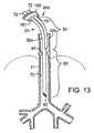
図13を参照するに、第4実施例の換気用カテーテル20dが示されている。本カテーテルは、図1の第1実施例と似ているが、第1実施例で取り付けられている膨張式カフ140(図1)を有していない。この、カフを有しない構造は、幼児や小さな子供のように気管が小さい場合に有益である。 Referring to FIG. 13, a ventilation catheter 20d of the fourth embodiment is shown. The catheter is similar to the first embodiment of FIG. 1, but does not have the inflatable cuff 140 (FIG. 1) attached in the first embodiment. This structure without a cuff is useful when the trachea is small like an infant or a small child.
本発明は好ましい実施例を用いて説明してきたが、発明の範囲は、これら実施例に限られるものでない。例えばカフ140(図10及び図11)やチェック弁170(図9)は、開示されている実施例におけるカテーテル20aないし20dのいずれにも適用することができる。したがって、本発明の範囲は様々な変形例に及び、添付の請求項で定められる。 Although the present invention has been described using preferred embodiments, the scope of the invention is not limited to these embodiments. For example, the cuff 140 (FIGS. 10 and 11) and the check valve 170 (FIG. 9) can be applied to any of the
20 換気用カテーテル
30 二重ルーメン部
31 隔壁
32a,32b ルーメン
42 遠位端部
52 分泌物回収システム
56 分泌物回収チャンバ
61 声帯
62 単一ルーメン部
140 拡張式カフ
150 咬合阻止具
170 チェック弁
190 凹陥部20
Claims (16)
Translated fromJapanese前記気道確保システムから送られる未使用の吸気用流体を患者の体内へ流入させ、使用済みの吸気用流体を前記患者の体内から前記気道確保システムへ還流させる遠位端部と、
第1のルーメンと第2のルーメンとを有し、前記患者の口腔から咽喉の間に収まる大きさの二重ルーメン部とを有し、
前記第1のルーメンは前記未使用の吸気用流体の通路と空気圧を介して接続され、前記第2のルーメンは前記呼気用流体の通路と空気圧を介して接続されている、換気用カテーテル。A ventilation catheter that has an unused inspiratory fluid passage and an expiratory fluid passage and is operatively secured to the airway securing system;
A distal end that allows unused inspiratory fluid from the airway securing system to flow into the patient's body and returns used inspiratory fluid from the patient's body to the airway securing system;
A first lumen and a second lumen, and a double lumen portion sized to fit between the patient's mouth and throat,
The ventilation catheter, wherein the first lumen is connected to the unused inspiratory fluid passageway via air pressure, and the second lumen is connected to the exhalation fluid passageway via air pressure.
請求項1に記載の換気用カテーテル。Furthermore, including an occlusion preventer slidably attached to the double lumen part,
The ventilation catheter according to claim 1.
Applications Claiming Priority (2)
| Application Number | Priority Date | Filing Date | Title |
|---|---|---|---|
| US62907404P | 2004-11-19 | 2004-11-19 | |
| PCT/CA2005/001783WO2006053446A1 (en) | 2004-11-19 | 2005-11-21 | Secretion clearing ventilation catheter and airway management system |
Publications (1)
| Publication Number | Publication Date |
|---|---|
| JP2008520290Atrue JP2008520290A (en) | 2008-06-19 |
Family
ID=36406812
Family Applications (1)
| Application Number | Title | Priority Date | Filing Date |
|---|---|---|---|
| JP2007541610APendingJP2008520290A (en) | 2004-11-19 | 2005-11-21 | Ventilation catheter and airway management system to remove secretions |
Country Status (5)
| Country | Link |
|---|---|
| US (4) | US20070068530A1 (en) |
| EP (1) | EP1814620B1 (en) |
| JP (1) | JP2008520290A (en) |
| CN (1) | CN101160148B (en) |
| WO (1) | WO2006053446A1 (en) |
Cited By (4)
| Publication number | Priority date | Publication date | Assignee | Title |
|---|---|---|---|---|
| JP2008023105A (en)* | 2006-07-21 | 2008-02-07 | Tokunaga Soki Kenkyusho:Kk | Trachea tube |
| KR101753299B1 (en) | 2016-01-26 | 2017-07-03 | 연세대학교 산학협력단 | Endotracheal tube and Endotracheal tube assembly |
| KR20200018395A (en)* | 2018-08-09 | 2020-02-19 | 센트럴 사우스 유니버시티 | Oropharyngeal Prayer Keeper |
| JP2025502553A (en)* | 2022-01-11 | 2025-01-24 | ガブリエリー,ノアム | System and method for safely delivering an efficient amount of oxygen to needed organs during cardiopulmonary resuscitation |
Families Citing this family (62)
| Publication number | Priority date | Publication date | Assignee | Title |
|---|---|---|---|---|
| FR2858236B1 (en)* | 2003-07-29 | 2006-04-28 | Airox | DEVICE AND METHOD FOR SUPPLYING RESPIRATORY GAS IN PRESSURE OR VOLUME |
| MX2007005937A (en) | 2004-11-16 | 2007-09-11 | Robert L Barry | Device and method for lung treatment. |
| CN101432037A (en)* | 2005-12-21 | 2009-05-13 | 韦拉索恩医学加拿大无限责任公司 | Secretion clearing patient airway management system |
| US8585645B2 (en)* | 2006-11-13 | 2013-11-19 | Uptake Medical Corp. | Treatment with high temperature vapor |
| US7993323B2 (en)* | 2006-11-13 | 2011-08-09 | Uptake Medical Corp. | High pressure and high temperature vapor catheters and systems |
| CA2625548C (en) | 2007-08-04 | 2012-04-10 | John A. Law | An airway intubation device |
| US8147532B2 (en)* | 2007-10-22 | 2012-04-03 | Uptake Medical Corp. | Determining patient-specific vapor treatment and delivery parameters |
| US8322335B2 (en) | 2007-10-22 | 2012-12-04 | Uptake Medical Corp. | Determining patient-specific vapor treatment and delivery parameters |
| US8231606B2 (en)* | 2008-03-14 | 2012-07-31 | Carefusion 207, Inc. | Method and device for removing fluid material from the airway above an endotracheal tube cuff |
| US8267085B2 (en)* | 2009-03-20 | 2012-09-18 | Nellcor Puritan Bennett Llc | Leak-compensated proportional assist ventilation |
| US8272380B2 (en)* | 2008-03-31 | 2012-09-25 | Nellcor Puritan Bennett, Llc | Leak-compensated pressure triggering in medical ventilators |
| US8746248B2 (en) | 2008-03-31 | 2014-06-10 | Covidien Lp | Determination of patient circuit disconnect in leak-compensated ventilatory support |
| US10207069B2 (en) | 2008-03-31 | 2019-02-19 | Covidien Lp | System and method for determining ventilator leakage during stable periods within a breath |
| US8457706B2 (en)* | 2008-05-16 | 2013-06-04 | Covidien Lp | Estimation of a physiological parameter using a neural network |
| US8302602B2 (en) | 2008-09-30 | 2012-11-06 | Nellcor Puritan Bennett Llc | Breathing assistance system with multiple pressure sensors |
| US20100249639A1 (en)* | 2009-01-20 | 2010-09-30 | Samir Bhatt | Airway management devices, endoscopic conduits, surgical kits, and methods of using the same |
| US8424521B2 (en) | 2009-02-27 | 2013-04-23 | Covidien Lp | Leak-compensated respiratory mechanics estimation in medical ventilators |
| US8434479B2 (en) | 2009-02-27 | 2013-05-07 | Covidien Lp | Flow rate compensation for transient thermal response of hot-wire anemometers |
| US20100218766A1 (en)* | 2009-02-27 | 2010-09-02 | Nellcor Puritan Bennett Llc | Customizable mandatory/spontaneous closed loop mode selection |
| US8418691B2 (en)* | 2009-03-20 | 2013-04-16 | Covidien Lp | Leak-compensated pressure regulated volume control ventilation |
| US9179831B2 (en) | 2009-11-30 | 2015-11-10 | King Systems Corporation | Visualization instrument |
| US8439037B2 (en)* | 2009-12-01 | 2013-05-14 | Covidien Lp | Exhalation valve assembly with integrated filter and flow sensor |
| US8469030B2 (en) | 2009-12-01 | 2013-06-25 | Covidien Lp | Exhalation valve assembly with selectable contagious/non-contagious latch |
| US8439036B2 (en) | 2009-12-01 | 2013-05-14 | Covidien Lp | Exhalation valve assembly with integral flow sensor |
| US8469031B2 (en) | 2009-12-01 | 2013-06-25 | Covidien Lp | Exhalation valve assembly with integrated filter |
| US20110126832A1 (en)* | 2009-12-01 | 2011-06-02 | Nellcor Puritan Bennett Llc | Exhalation Valve Assembly |
| USD655809S1 (en) | 2010-04-27 | 2012-03-13 | Nellcor Puritan Bennett Llc | Valve body with integral flow meter for an exhalation module |
| USD653749S1 (en) | 2010-04-27 | 2012-02-07 | Nellcor Puritan Bennett Llc | Exhalation module filter body |
| USD655405S1 (en) | 2010-04-27 | 2012-03-06 | Nellcor Puritan Bennett Llc | Filter and valve body for an exhalation module |
| US8555887B2 (en) | 2010-04-30 | 2013-10-15 | Covidien Lp | Tracheal tube with dividing membrane |
| EP2588177B1 (en)* | 2010-06-30 | 2020-01-01 | St. Michael's Hospital | System for patient-synchronized ventilatory assist with endotracheal through-flow |
| US9629971B2 (en) | 2011-04-29 | 2017-04-25 | Covidien Lp | Methods and systems for exhalation control and trajectory optimization |
| US9364624B2 (en) | 2011-12-07 | 2016-06-14 | Covidien Lp | Methods and systems for adaptive base flow |
| US9821130B2 (en) | 2011-12-08 | 2017-11-21 | Avent, Inc. | Multi-diameter pediatric tracheal cuff |
| US9498589B2 (en) | 2011-12-31 | 2016-11-22 | Covidien Lp | Methods and systems for adaptive base flow and leak compensation |
| US9144658B2 (en) | 2012-04-30 | 2015-09-29 | Covidien Lp | Minimizing imposed expiratory resistance of mechanical ventilator by optimizing exhalation valve control |
| KR101227062B1 (en)* | 2012-06-26 | 2013-02-06 | (주)엠큐어 | A catheter for skin surgical devices |
| USD731049S1 (en) | 2013-03-05 | 2015-06-02 | Covidien Lp | EVQ housing of an exhalation module |
| USD701601S1 (en) | 2013-03-08 | 2014-03-25 | Covidien Lp | Condensate vial of an exhalation module |
| USD736905S1 (en) | 2013-03-08 | 2015-08-18 | Covidien Lp | Exhalation module EVQ housing |
| USD731048S1 (en) | 2013-03-08 | 2015-06-02 | Covidien Lp | EVQ diaphragm of an exhalation module |
| USD693001S1 (en) | 2013-03-08 | 2013-11-05 | Covidien Lp | Neonate expiratory filter assembly of an exhalation module |
| USD744095S1 (en) | 2013-03-08 | 2015-11-24 | Covidien Lp | Exhalation module EVQ internal flow sensor |
| USD692556S1 (en) | 2013-03-08 | 2013-10-29 | Covidien Lp | Expiratory filter body of an exhalation module |
| USD731065S1 (en) | 2013-03-08 | 2015-06-02 | Covidien Lp | EVQ pressure sensor filter of an exhalation module |
| US9950135B2 (en) | 2013-03-15 | 2018-04-24 | Covidien Lp | Maintaining an exhalation valve sensor assembly |
| AU2014240225A1 (en) | 2013-10-01 | 2015-04-16 | Uptake Medical Technology Inc. | Preferential volume reduction of diseased segments of a heterogeneous lobe |
| US9675771B2 (en) | 2013-10-18 | 2017-06-13 | Covidien Lp | Methods and systems for leak estimation |
| US10485604B2 (en) | 2014-12-02 | 2019-11-26 | Uptake Medical Technology Inc. | Vapor treatment of lung nodules and tumors |
| US10531906B2 (en) | 2015-02-02 | 2020-01-14 | Uptake Medical Technology Inc. | Medical vapor generator |
| EP4186548A1 (en) | 2015-04-02 | 2023-05-31 | Hill-Rom Services PTE. LTD. | Mask leakage detection for a respiratory device |
| USD775345S1 (en) | 2015-04-10 | 2016-12-27 | Covidien Lp | Ventilator console |
| JP6743189B2 (en)* | 2016-05-16 | 2020-08-19 | テレフレックス、ライフ、サイエンシーズ、アンリミテッド、カンパニーTeleflex Life Sciences Unlimited Company | Catheter dynamic tip occlusion |
| US11129673B2 (en) | 2017-05-05 | 2021-09-28 | Uptake Medical Technology Inc. | Extra-airway vapor ablation for treating airway constriction in patients with asthma and COPD |
| US11344364B2 (en) | 2017-09-07 | 2022-05-31 | Uptake Medical Technology Inc. | Screening method for a target nerve to ablate for the treatment of inflammatory lung disease |
| US11350988B2 (en) | 2017-09-11 | 2022-06-07 | Uptake Medical Technology Inc. | Bronchoscopic multimodality lung tumor treatment |
| USD845467S1 (en) | 2017-09-17 | 2019-04-09 | Uptake Medical Technology Inc. | Hand-piece for medical ablation catheter |
| US11419658B2 (en) | 2017-11-06 | 2022-08-23 | Uptake Medical Technology Inc. | Method for treating emphysema with condensable thermal vapor |
| US11490946B2 (en) | 2017-12-13 | 2022-11-08 | Uptake Medical Technology Inc. | Vapor ablation handpiece |
| US11653927B2 (en) | 2019-02-18 | 2023-05-23 | Uptake Medical Technology Inc. | Vapor ablation treatment of obstructive lung disease |
| US11896767B2 (en) | 2020-03-20 | 2024-02-13 | Covidien Lp | Model-driven system integration in medical ventilators |
| US12203668B2 (en) | 2022-08-29 | 2025-01-21 | Honeywell International Inc. | Air quality monitoring device and associated method of manufacturing |
Citations (4)
| Publication number | Priority date | Publication date | Assignee | Title |
|---|---|---|---|---|
| JPH0847535A (en)* | 1994-08-05 | 1996-02-20 | Naoki Yahagi | Bite block for fixing tracheal tube |
| JPH09173455A (en)* | 1995-12-01 | 1997-07-08 | Siemens Elema Ab | Method for ventilator system and ventilator system |
| JP2002532206A (en)* | 1998-12-22 | 2002-10-02 | レスピロニクス・インコーポレイテッド | Tracheal gas blower, blower accessory and blown gas supply method |
| WO2003055553A1 (en)* | 2001-12-21 | 2003-07-10 | Eidon, Llc | Surface energy assisted fluid transport system and method |
Family Cites Families (36)
| Publication number | Priority date | Publication date | Assignee | Title |
|---|---|---|---|---|
| DE1441391A1 (en)* | 1962-05-12 | 1969-01-23 | Willy Ruesch Kg | Ventilation device |
| US3682166A (en)* | 1970-07-29 | 1972-08-08 | Harvey Barry Jacobs | Emergency percutaneous trans-tracheal high flow oxygen catheter-type resuscitator for restoration of breathing in non-breathing patients |
| US3815606A (en)* | 1972-09-21 | 1974-06-11 | C Mazal | Endotracheal catheter |
| US4036210A (en)* | 1975-06-09 | 1977-07-19 | Campbell Roy L | Double lumened catheter |
| US4022219A (en)* | 1975-07-28 | 1977-05-10 | Edward Basta | Endotracheal device |
| DE2535191A1 (en)* | 1975-08-07 | 1977-02-24 | Ulrich Joachim Pfeiffer | Endotracheal respiration system with minimum dead space - having separate inhalation and exhalation lines and separate gas line |
| US4166467A (en)* | 1977-08-08 | 1979-09-04 | Metatech Corporation | Bite block for endotracheal tube |
| US4300550A (en)* | 1978-04-26 | 1981-11-17 | Becton, Dickinson And Company | Suction and oxygenation catheter |
| US4416273A (en)* | 1981-06-15 | 1983-11-22 | Grimes Jerry L | Connector valve assembly for endotracheal tubes |
| US4693243A (en)* | 1983-01-14 | 1987-09-15 | Buras Sharon Y | Conduit system for directly administering topical anaesthesia to blocked laryngeal-tracheal areas |
| US4995387A (en)* | 1984-02-08 | 1991-02-26 | Jinotti Walter J | Dual-purpose catheter |
| DE8607358U1 (en)* | 1986-03-18 | 1986-05-28 | Ruß, Jürgen, 5300 Bonn | Tubular, flexible probe for insertion into the trachea and bronchi |
| US4850350A (en)* | 1986-06-23 | 1989-07-25 | Sheridan Catheter Corp. | Closed system combined suction and ventilation devices |
| US4840173A (en)* | 1988-02-22 | 1989-06-20 | Porter Iii John W | Endotracheal tube combination |
| US4856510A (en)* | 1988-04-06 | 1989-08-15 | Kowalewski Ryszard J | Tracheal tube inflator |
| US5038766A (en)* | 1989-11-08 | 1991-08-13 | Parker Jeffrey D | Blind orolaryngeal and oroesophageal guiding and aiming device |
| DE69109268T2 (en)* | 1990-02-21 | 1995-09-14 | Smiths Industries Plc | COMPOSED TRACHEAL TUBE. |
| US5067497A (en)* | 1990-03-16 | 1991-11-26 | Progressive Medical Design, Inc. | Intubation device with adjustable suction means above the cuff |
| US5339808A (en)* | 1991-04-02 | 1994-08-23 | Don Michael T Anthony | Endotracheal-esophageal intubation devices |
| US5551420A (en)* | 1993-11-09 | 1996-09-03 | Cprx, Inc. | CPR device and method with structure for increasing the duration and magnitude of negative intrathoracic pressures |
| US5499625A (en)* | 1994-01-27 | 1996-03-19 | The Kendall Company | Esophageal-tracheal double lumen airway |
| US5582167A (en)* | 1994-03-02 | 1996-12-10 | Thomas Jefferson University | Methods and apparatus for reducing tracheal infection using subglottic irrigation, drainage and servoregulation of endotracheal tube cuff pressure |
| US5520175A (en)* | 1995-05-22 | 1996-05-28 | Fry; William R. | Endotracheal tube with suctioning means |
| US5706830A (en)* | 1996-05-06 | 1998-01-13 | South Alabama Medical Science Foundation | Liquid ventilator system and use thereof |
| US5957134A (en)* | 1997-11-18 | 1999-09-28 | Lee; Han Shik | Anesthesia delivery system |
| US6655377B2 (en)* | 1997-12-01 | 2003-12-02 | Saturn Biomedical Systems Inc. | Intubation instrument |
| US6142144A (en)* | 1997-12-01 | 2000-11-07 | Pacey; John A. | Intubation instrument |
| US6543447B2 (en)* | 1997-12-01 | 2003-04-08 | Saturn Biomedical Systems Inc | Intubation instrument |
| JP3540745B2 (en)* | 1998-03-09 | 2004-07-07 | ドクトア・フレッド・ゲーベル・パテントフェアバルトゥング・ゲー・エム・ベー・ハー | Tracheal ventilation device |
| GB9818558D0 (en)* | 1998-08-27 | 1998-10-21 | Craft Timothy M Dr | An airway bite protector |
| US6443156B1 (en)* | 2000-08-02 | 2002-09-03 | Laura E. Niklason | Separable double lumen endotracheal tube |
| UY26609A1 (en)* | 2001-03-07 | 2002-09-30 | Electroplast S A | "IMPROVEMENTS IN TRAQUEO-BRONCHIAL PROBES". |
| DE10123278C1 (en)* | 2001-05-10 | 2002-06-13 | Univ Hamburg | Breathing device used in intensive care or during anesthesia comprises a respirator, an outlet, an inhalation tube, a twin-channel endotracheal tube, flow meters, pressure meters, and an evaluation device |
| US6520183B2 (en)* | 2001-06-11 | 2003-02-18 | Memorial Sloan-Kettering Cancer Center | Double endobronchial catheter for one lung isolation anesthesia and surgery |
| US8978657B2 (en)* | 2010-07-29 | 2015-03-17 | Covidien Lp | Dual-lumen tracheal tube with shaped lumen divider |
| US9788755B2 (en)* | 2011-05-26 | 2017-10-17 | Covidien Lp | Illumination systems and devices for tracheal tubes |
- 2005
- 2005-11-21USUS11/285,743patent/US20070068530A1/ennot_activeAbandoned
- 2005-11-21JPJP2007541610Apatent/JP2008520290A/enactivePending
- 2005-11-21EPEP05810634.5Apatent/EP1814620B1/ennot_activeNot-in-force
- 2005-11-21WOPCT/CA2005/001783patent/WO2006053446A1/enactiveApplication Filing
- 2005-11-21CNCN2005800464819Apatent/CN101160148B/ennot_activeExpired - Fee Related
- 2012
- 2012-06-04USUS13/488,258patent/US20130056007A1/ennot_activeAbandoned
- 2014
- 2014-05-22USUS14/284,799patent/US20140251339A1/ennot_activeAbandoned
- 2019
- 2019-03-12USUS16/351,392patent/US20200009339A1/ennot_activeAbandoned
Patent Citations (4)
| Publication number | Priority date | Publication date | Assignee | Title |
|---|---|---|---|---|
| JPH0847535A (en)* | 1994-08-05 | 1996-02-20 | Naoki Yahagi | Bite block for fixing tracheal tube |
| JPH09173455A (en)* | 1995-12-01 | 1997-07-08 | Siemens Elema Ab | Method for ventilator system and ventilator system |
| JP2002532206A (en)* | 1998-12-22 | 2002-10-02 | レスピロニクス・インコーポレイテッド | Tracheal gas blower, blower accessory and blown gas supply method |
| WO2003055553A1 (en)* | 2001-12-21 | 2003-07-10 | Eidon, Llc | Surface energy assisted fluid transport system and method |
Cited By (5)
| Publication number | Priority date | Publication date | Assignee | Title |
|---|---|---|---|---|
| JP2008023105A (en)* | 2006-07-21 | 2008-02-07 | Tokunaga Soki Kenkyusho:Kk | Trachea tube |
| KR101753299B1 (en) | 2016-01-26 | 2017-07-03 | 연세대학교 산학협력단 | Endotracheal tube and Endotracheal tube assembly |
| KR20200018395A (en)* | 2018-08-09 | 2020-02-19 | 센트럴 사우스 유니버시티 | Oropharyngeal Prayer Keeper |
| KR102340969B1 (en) | 2018-08-09 | 2021-12-17 | 센트럴 사우스 유니버시티 | oropharyngeal airway maintainer |
| JP2025502553A (en)* | 2022-01-11 | 2025-01-24 | ガブリエリー,ノアム | System and method for safely delivering an efficient amount of oxygen to needed organs during cardiopulmonary resuscitation |
Also Published As
| Publication number | Publication date |
|---|---|
| CN101160148A (en) | 2008-04-09 |
| US20140251339A1 (en) | 2014-09-11 |
| CN101160148B (en) | 2013-03-27 |
| US20070068530A1 (en) | 2007-03-29 |
| EP1814620A1 (en) | 2007-08-08 |
| EP1814620A4 (en) | 2010-06-30 |
| EP1814620B1 (en) | 2016-07-06 |
| US20130056007A1 (en) | 2013-03-07 |
| US20200009339A1 (en) | 2020-01-09 |
| WO2006053446A1 (en) | 2006-05-26 |
Similar Documents
| Publication | Publication Date | Title |
|---|---|---|
| US20210386949A1 (en) | Secretion clearing patient airway management system | |
| JP2008520290A (en) | Ventilation catheter and airway management system to remove secretions | |
| JP3199732B2 (en) | Endotracheal tube with artificial ventilation | |
| US6609521B1 (en) | Endotracheal tube | |
| US5291882A (en) | Multi-lumen ITPV endotracheal tube | |
| CN102355920B (en) | Jet ventilation catheter | |
| US8535265B2 (en) | Tracheal catheter with suction lumen port in close proximity to the cuff | |
| US8602030B2 (en) | Tracheal tubes with improved secretion removal systems | |
| US20070044807A1 (en) | Multilumen tracheal catheter with rinse lumen | |
| KR20010022859A (en) | Endotracheal or tracheotomy tube | |
| JP2000152995A (en) | Thin artificial air duct device | |
| EP4025283B1 (en) | Pharyngeal tube for establishing a patent airway | |
| CN222788283U (en) | Cuff-mounted endotracheal tube | |
| CN118743809A (en) | One-time endotracheal interventional therapy for tracheal intubation | |
| MXPA00001328A (en) | Endotracheal or tracheotomy tube |
Legal Events
| Date | Code | Title | Description |
|---|---|---|---|
| A621 | Written request for application examination | Free format text:JAPANESE INTERMEDIATE CODE: A621 Effective date:20081110 | |
| A977 | Report on retrieval | Free format text:JAPANESE INTERMEDIATE CODE: A971007 Effective date:20110127 | |
| A131 | Notification of reasons for refusal | Free format text:JAPANESE INTERMEDIATE CODE: A131 Effective date:20110201 | |
| A601 | Written request for extension of time | Free format text:JAPANESE INTERMEDIATE CODE: A601 Effective date:20110422 | |
| A602 | Written permission of extension of time | Free format text:JAPANESE INTERMEDIATE CODE: A602 Effective date:20110506 | |
| A601 | Written request for extension of time | Free format text:JAPANESE INTERMEDIATE CODE: A601 Effective date:20110524 | |
| A602 | Written permission of extension of time | Free format text:JAPANESE INTERMEDIATE CODE: A602 Effective date:20110531 | |
| A601 | Written request for extension of time | Free format text:JAPANESE INTERMEDIATE CODE: A601 Effective date:20110623 | |
| A602 | Written permission of extension of time | Free format text:JAPANESE INTERMEDIATE CODE: A602 Effective date:20110704 | |
| A02 | Decision of refusal | Free format text:JAPANESE INTERMEDIATE CODE: A02 Effective date:20120214 |