JP2008517800A - Plastic composite article and manufacturing method thereof - Google Patents
Plastic composite article and manufacturing method thereofDownload PDFInfo
- Publication number
- JP2008517800A JP2008517800AJP2007538025AJP2007538025AJP2008517800AJP 2008517800 AJP2008517800 AJP 2008517800AJP 2007538025 AJP2007538025 AJP 2007538025AJP 2007538025 AJP2007538025 AJP 2007538025AJP 2008517800 AJP2008517800 AJP 2008517800A
- Authority
- JP
- Japan
- Prior art keywords
- intermediate product
- product form
- elongate member
- component
- thermoplastic
- Prior art date
- Legal status (The legal status is an assumption and is not a legal conclusion. Google has not performed a legal analysis and makes no representation as to the accuracy of the status listed.)
- Pending
Links
Images


Classifications
- B—PERFORMING OPERATIONS; TRANSPORTING
- B29—WORKING OF PLASTICS; WORKING OF SUBSTANCES IN A PLASTIC STATE IN GENERAL
- B29C—SHAPING OR JOINING OF PLASTICS; SHAPING OF MATERIAL IN A PLASTIC STATE, NOT OTHERWISE PROVIDED FOR; AFTER-TREATMENT OF THE SHAPED PRODUCTS, e.g. REPAIRING
- B29C43/00—Compression moulding, i.e. applying external pressure to flow the moulding material; Apparatus therefor
- B29C43/32—Component parts, details or accessories; Auxiliary operations
- B29C43/36—Moulds for making articles of definite length, i.e. discrete articles
- B—PERFORMING OPERATIONS; TRANSPORTING
- B29—WORKING OF PLASTICS; WORKING OF SUBSTANCES IN A PLASTIC STATE IN GENERAL
- B29C—SHAPING OR JOINING OF PLASTICS; SHAPING OF MATERIAL IN A PLASTIC STATE, NOT OTHERWISE PROVIDED FOR; AFTER-TREATMENT OF THE SHAPED PRODUCTS, e.g. REPAIRING
- B29C51/00—Shaping by thermoforming, i.e. shaping sheets or sheet like preforms after heating, e.g. shaping sheets in matched moulds or by deep-drawing; Apparatus therefor
- B29C51/002—Shaping by thermoforming, i.e. shaping sheets or sheet like preforms after heating, e.g. shaping sheets in matched moulds or by deep-drawing; Apparatus therefor characterised by the choice of material
- B29C51/004—Textile or other fibrous material made from plastics fibres
- B—PERFORMING OPERATIONS; TRANSPORTING
- B29—WORKING OF PLASTICS; WORKING OF SUBSTANCES IN A PLASTIC STATE IN GENERAL
- B29C—SHAPING OR JOINING OF PLASTICS; SHAPING OF MATERIAL IN A PLASTIC STATE, NOT OTHERWISE PROVIDED FOR; AFTER-TREATMENT OF THE SHAPED PRODUCTS, e.g. REPAIRING
- B29C70/00—Shaping composites, i.e. plastics material comprising reinforcements, fillers or preformed parts, e.g. inserts
- B29C70/04—Shaping composites, i.e. plastics material comprising reinforcements, fillers or preformed parts, e.g. inserts comprising reinforcements only, e.g. self-reinforcing plastics
- B—PERFORMING OPERATIONS; TRANSPORTING
- B32—LAYERED PRODUCTS
- B32B—LAYERED PRODUCTS, i.e. PRODUCTS BUILT-UP OF STRATA OF FLAT OR NON-FLAT, e.g. CELLULAR OR HONEYCOMB, FORM
- B32B1/00—Layered products having a non-planar shape
- B—PERFORMING OPERATIONS; TRANSPORTING
- B32—LAYERED PRODUCTS
- B32B—LAYERED PRODUCTS, i.e. PRODUCTS BUILT-UP OF STRATA OF FLAT OR NON-FLAT, e.g. CELLULAR OR HONEYCOMB, FORM
- B32B27/00—Layered products comprising a layer of synthetic resin
- B32B27/32—Layered products comprising a layer of synthetic resin comprising polyolefins
- D—TEXTILES; PAPER
- D03—WEAVING
- D03D—WOVEN FABRICS; METHODS OF WEAVING; LOOMS
- D03D15/00—Woven fabrics characterised by the material, structure or properties of the fibres, filaments, yarns, threads or other warp or weft elements used
- D03D15/20—Woven fabrics characterised by the material, structure or properties of the fibres, filaments, yarns, threads or other warp or weft elements used characterised by the material of the fibres or filaments constituting the yarns or threads
- D03D15/283—Woven fabrics characterised by the material, structure or properties of the fibres, filaments, yarns, threads or other warp or weft elements used characterised by the material of the fibres or filaments constituting the yarns or threads synthetic polymer-based, e.g. polyamide or polyester fibres
- D—TEXTILES; PAPER
- D03—WEAVING
- D03D—WOVEN FABRICS; METHODS OF WEAVING; LOOMS
- D03D15/00—Woven fabrics characterised by the material, structure or properties of the fibres, filaments, yarns, threads or other warp or weft elements used
- D03D15/40—Woven fabrics characterised by the material, structure or properties of the fibres, filaments, yarns, threads or other warp or weft elements used characterised by the structure of the yarns or threads
- D03D15/44—Woven fabrics characterised by the material, structure or properties of the fibres, filaments, yarns, threads or other warp or weft elements used characterised by the structure of the yarns or threads with specific cross-section or surface shape
- D03D15/46—Flat yarns, e.g. tapes or films
- B—PERFORMING OPERATIONS; TRANSPORTING
- B29—WORKING OF PLASTICS; WORKING OF SUBSTANCES IN A PLASTIC STATE IN GENERAL
- B29C—SHAPING OR JOINING OF PLASTICS; SHAPING OF MATERIAL IN A PLASTIC STATE, NOT OTHERWISE PROVIDED FOR; AFTER-TREATMENT OF THE SHAPED PRODUCTS, e.g. REPAIRING
- B29C43/00—Compression moulding, i.e. applying external pressure to flow the moulding material; Apparatus therefor
- B29C43/32—Component parts, details or accessories; Auxiliary operations
- B29C43/36—Moulds for making articles of definite length, i.e. discrete articles
- B29C2043/3602—Moulds for making articles of definite length, i.e. discrete articles with means for positioning, fastening or clamping the material to be formed or preforms inside the mould
- B—PERFORMING OPERATIONS; TRANSPORTING
- B29—WORKING OF PLASTICS; WORKING OF SUBSTANCES IN A PLASTIC STATE IN GENERAL
- B29C—SHAPING OR JOINING OF PLASTICS; SHAPING OF MATERIAL IN A PLASTIC STATE, NOT OTHERWISE PROVIDED FOR; AFTER-TREATMENT OF THE SHAPED PRODUCTS, e.g. REPAIRING
- B29C43/00—Compression moulding, i.e. applying external pressure to flow the moulding material; Apparatus therefor
- B29C43/32—Component parts, details or accessories; Auxiliary operations
- B29C43/36—Moulds for making articles of definite length, i.e. discrete articles
- B29C43/361—Moulds for making articles of definite length, i.e. discrete articles with pressing members independently movable of the parts for opening or closing the mould, e.g. movable pistons
- B29C2043/3615—Forming elements, e.g. mandrels or rams or stampers or pistons or plungers or punching devices
- B29C2043/3631—Forming elements, e.g. mandrels or rams or stampers or pistons or plungers or punching devices moving in a frame for pressing and stretching; material being subjected to compressing stretching
- B—PERFORMING OPERATIONS; TRANSPORTING
- B29—WORKING OF PLASTICS; WORKING OF SUBSTANCES IN A PLASTIC STATE IN GENERAL
- B29K—INDEXING SCHEME ASSOCIATED WITH SUBCLASSES B29B, B29C OR B29D, RELATING TO MOULDING MATERIALS OR TO MATERIALS FOR MOULDS, REINFORCEMENTS, FILLERS OR PREFORMED PARTS, e.g. INSERTS
- B29K2023/00—Use of polyalkenes or derivatives thereof as moulding material
- B29K2023/04—Polymers of ethylene
- B29K2023/06—PE, i.e. polyethylene
- B29K2023/0608—PE, i.e. polyethylene characterised by its density
- B29K2023/0641—MDPE, i.e. medium density polyethylene
- B—PERFORMING OPERATIONS; TRANSPORTING
- B29—WORKING OF PLASTICS; WORKING OF SUBSTANCES IN A PLASTIC STATE IN GENERAL
- B29K—INDEXING SCHEME ASSOCIATED WITH SUBCLASSES B29B, B29C OR B29D, RELATING TO MOULDING MATERIALS OR TO MATERIALS FOR MOULDS, REINFORCEMENTS, FILLERS OR PREFORMED PARTS, e.g. INSERTS
- B29K2023/00—Use of polyalkenes or derivatives thereof as moulding material
- B29K2023/10—Polymers of propylene
- B29K2023/12—PP, i.e. polypropylene
- D—TEXTILES; PAPER
- D10—INDEXING SCHEME ASSOCIATED WITH SUBLASSES OF SECTION D, RELATING TO TEXTILES
- D10B—INDEXING SCHEME ASSOCIATED WITH SUBLASSES OF SECTION D, RELATING TO TEXTILES
- D10B2321/00—Fibres made from polymers obtained by reactions only involving carbon-to-carbon unsaturated bonds
- D10B2321/02—Fibres made from polymers obtained by reactions only involving carbon-to-carbon unsaturated bonds polyolefins
- D10B2321/021—Fibres made from polymers obtained by reactions only involving carbon-to-carbon unsaturated bonds polyolefins polyethylene
- D—TEXTILES; PAPER
- D10—INDEXING SCHEME ASSOCIATED WITH SUBLASSES OF SECTION D, RELATING TO TEXTILES
- D10B—INDEXING SCHEME ASSOCIATED WITH SUBLASSES OF SECTION D, RELATING TO TEXTILES
- D10B2321/00—Fibres made from polymers obtained by reactions only involving carbon-to-carbon unsaturated bonds
- D10B2321/02—Fibres made from polymers obtained by reactions only involving carbon-to-carbon unsaturated bonds polyolefins
- D10B2321/022—Fibres made from polymers obtained by reactions only involving carbon-to-carbon unsaturated bonds polyolefins polypropylene
- D—TEXTILES; PAPER
- D10—INDEXING SCHEME ASSOCIATED WITH SUBLASSES OF SECTION D, RELATING TO TEXTILES
- D10B—INDEXING SCHEME ASSOCIATED WITH SUBLASSES OF SECTION D, RELATING TO TEXTILES
- D10B2401/00—Physical properties
- D10B2401/04—Heat-responsive characteristics
- D10B2401/041—Heat-responsive characteristics thermoplastic; thermosetting
- D—TEXTILES; PAPER
- D10—INDEXING SCHEME ASSOCIATED WITH SUBLASSES OF SECTION D, RELATING TO TEXTILES
- D10B—INDEXING SCHEME ASSOCIATED WITH SUBLASSES OF SECTION D, RELATING TO TEXTILES
- D10B2505/00—Industrial
- D10B2505/02—Reinforcing materials; Prepregs
- Y—GENERAL TAGGING OF NEW TECHNOLOGICAL DEVELOPMENTS; GENERAL TAGGING OF CROSS-SECTIONAL TECHNOLOGIES SPANNING OVER SEVERAL SECTIONS OF THE IPC; TECHNICAL SUBJECTS COVERED BY FORMER USPC CROSS-REFERENCE ART COLLECTIONS [XRACs] AND DIGESTS
- Y10—TECHNICAL SUBJECTS COVERED BY FORMER USPC
- Y10T—TECHNICAL SUBJECTS COVERED BY FORMER US CLASSIFICATION
- Y10T156/00—Adhesive bonding and miscellaneous chemical manufacture
- Y10T156/10—Methods of surface bonding and/or assembly therefor
- Y—GENERAL TAGGING OF NEW TECHNOLOGICAL DEVELOPMENTS; GENERAL TAGGING OF CROSS-SECTIONAL TECHNOLOGIES SPANNING OVER SEVERAL SECTIONS OF THE IPC; TECHNICAL SUBJECTS COVERED BY FORMER USPC CROSS-REFERENCE ART COLLECTIONS [XRACs] AND DIGESTS
- Y10—TECHNICAL SUBJECTS COVERED BY FORMER USPC
- Y10T—TECHNICAL SUBJECTS COVERED BY FORMER US CLASSIFICATION
- Y10T428/00—Stock material or miscellaneous articles
- Y10T428/13—Hollow or container type article [e.g., tube, vase, etc.]
- Y10T428/1303—Paper containing [e.g., paperboard, cardboard, fiberboard, etc.]
- Y—GENERAL TAGGING OF NEW TECHNOLOGICAL DEVELOPMENTS; GENERAL TAGGING OF CROSS-SECTIONAL TECHNOLOGIES SPANNING OVER SEVERAL SECTIONS OF THE IPC; TECHNICAL SUBJECTS COVERED BY FORMER USPC CROSS-REFERENCE ART COLLECTIONS [XRACs] AND DIGESTS
- Y10—TECHNICAL SUBJECTS COVERED BY FORMER USPC
- Y10T—TECHNICAL SUBJECTS COVERED BY FORMER US CLASSIFICATION
- Y10T428/00—Stock material or miscellaneous articles
- Y10T428/13—Hollow or container type article [e.g., tube, vase, etc.]
- Y10T428/1352—Polymer or resin containing [i.e., natural or synthetic]
- Y10T428/1355—Elemental metal containing [e.g., substrate, foil, film, coating, etc.]
- Y10T428/1359—Three or more layers [continuous layer]
- Y—GENERAL TAGGING OF NEW TECHNOLOGICAL DEVELOPMENTS; GENERAL TAGGING OF CROSS-SECTIONAL TECHNOLOGIES SPANNING OVER SEVERAL SECTIONS OF THE IPC; TECHNICAL SUBJECTS COVERED BY FORMER USPC CROSS-REFERENCE ART COLLECTIONS [XRACs] AND DIGESTS
- Y10—TECHNICAL SUBJECTS COVERED BY FORMER USPC
- Y10T—TECHNICAL SUBJECTS COVERED BY FORMER US CLASSIFICATION
- Y10T428/00—Stock material or miscellaneous articles
- Y10T428/13—Hollow or container type article [e.g., tube, vase, etc.]
- Y10T428/1352—Polymer or resin containing [i.e., natural or synthetic]
- Y10T428/139—Open-ended, self-supporting conduit, cylinder, or tube-type article
- Y10T428/1393—Multilayer [continuous layer]
- Y—GENERAL TAGGING OF NEW TECHNOLOGICAL DEVELOPMENTS; GENERAL TAGGING OF CROSS-SECTIONAL TECHNOLOGIES SPANNING OVER SEVERAL SECTIONS OF THE IPC; TECHNICAL SUBJECTS COVERED BY FORMER USPC CROSS-REFERENCE ART COLLECTIONS [XRACs] AND DIGESTS
- Y10—TECHNICAL SUBJECTS COVERED BY FORMER USPC
- Y10T—TECHNICAL SUBJECTS COVERED BY FORMER US CLASSIFICATION
- Y10T428/00—Stock material or miscellaneous articles
- Y10T428/24—Structurally defined web or sheet [e.g., overall dimension, etc.]
- Y10T428/24942—Structurally defined web or sheet [e.g., overall dimension, etc.] including components having same physical characteristic in differing degree
- Y10T428/2495—Thickness [relative or absolute]
- Y10T428/24967—Absolute thicknesses specified
- Y10T428/24975—No layer or component greater than 5 mils thick
- Y—GENERAL TAGGING OF NEW TECHNOLOGICAL DEVELOPMENTS; GENERAL TAGGING OF CROSS-SECTIONAL TECHNOLOGIES SPANNING OVER SEVERAL SECTIONS OF THE IPC; TECHNICAL SUBJECTS COVERED BY FORMER USPC CROSS-REFERENCE ART COLLECTIONS [XRACs] AND DIGESTS
- Y10—TECHNICAL SUBJECTS COVERED BY FORMER USPC
- Y10T—TECHNICAL SUBJECTS COVERED BY FORMER US CLASSIFICATION
- Y10T428/00—Stock material or miscellaneous articles
- Y10T428/26—Web or sheet containing structurally defined element or component, the element or component having a specified physical dimension
- Y10T428/263—Coating layer not in excess of 5 mils thick or equivalent
- Y10T428/264—Up to 3 mils
- Y—GENERAL TAGGING OF NEW TECHNOLOGICAL DEVELOPMENTS; GENERAL TAGGING OF CROSS-SECTIONAL TECHNOLOGIES SPANNING OVER SEVERAL SECTIONS OF THE IPC; TECHNICAL SUBJECTS COVERED BY FORMER USPC CROSS-REFERENCE ART COLLECTIONS [XRACs] AND DIGESTS
- Y10—TECHNICAL SUBJECTS COVERED BY FORMER USPC
- Y10T—TECHNICAL SUBJECTS COVERED BY FORMER US CLASSIFICATION
- Y10T428/00—Stock material or miscellaneous articles
- Y10T428/31504—Composite [nonstructural laminate]
- Y10T428/31855—Of addition polymer from unsaturated monomers
- Y10T428/31909—Next to second addition polymer from unsaturated monomers
- Y10T428/31913—Monoolefin polymer
- Y—GENERAL TAGGING OF NEW TECHNOLOGICAL DEVELOPMENTS; GENERAL TAGGING OF CROSS-SECTIONAL TECHNOLOGIES SPANNING OVER SEVERAL SECTIONS OF THE IPC; TECHNICAL SUBJECTS COVERED BY FORMER USPC CROSS-REFERENCE ART COLLECTIONS [XRACs] AND DIGESTS
- Y10—TECHNICAL SUBJECTS COVERED BY FORMER USPC
- Y10T—TECHNICAL SUBJECTS COVERED BY FORMER US CLASSIFICATION
- Y10T442/00—Fabric [woven, knitted, or nonwoven textile or cloth, etc.]
- Y10T442/20—Coated or impregnated woven, knit, or nonwoven fabric which is not [a] associated with another preformed layer or fiber layer or, [b] with respect to woven and knit, characterized, respectively, by a particular or differential weave or knit, wherein the coating or impregnation is neither a foamed material nor a free metal or alloy layer
- Y10T442/2008—Fabric composed of a fiber or strand which is of specific structural definition
Landscapes
- Engineering & Computer Science (AREA)
- Mechanical Engineering (AREA)
- Textile Engineering (AREA)
- Chemical & Material Sciences (AREA)
- Composite Materials (AREA)
- Laminated Bodies (AREA)
- Compositions Of Macromolecular Compounds (AREA)
- Rigid Pipes And Flexible Pipes (AREA)
- Casting Or Compression Moulding Of Plastics Or The Like (AREA)
- Shaping Of Tube Ends By Bending Or Straightening (AREA)
- Shaping By String And By Release Of Stress In Plastics And The Like (AREA)
- Materials For Medical Uses (AREA)
- Moulding By Coating Moulds (AREA)
- Injection Moulding Of Plastics Or The Like (AREA)
- Moulds For Moulding Plastics Or The Like (AREA)
- Blow-Moulding Or Thermoforming Of Plastics Or The Like (AREA)
- Processing And Handling Of Plastics And Other Materials For Molding In General (AREA)
- Pharmaceuticals Containing Other Organic And Inorganic Compounds (AREA)
- Compounds Of Unknown Constitution (AREA)
- Reinforced Plastic Materials (AREA)
- Lining Or Joining Of Plastics Or The Like (AREA)
Abstract
Translated fromJapaneseDescription
Translated fromJapanese優先権主張
本件は、2004年10月22日に出願された米国仮特許出願第60/621,463号(代理人事件番号(Attorney Docket No.)63863;1062−041P1);2005年9月16日に出願された米国仮特許出願第60/717,965号(代理人事件番号63863B;1062−041P2);2005年9月16日に出願された米国仮特許出願第60/718,025号(代理人事件番号64371;1062−051P1);及び2005年10月11日に出願された米国仮特許出願第60/725,399号(代理人事件番号63863C;1062−041P3)(速達郵便番号EV789808245US)に関する優先権及び出願日の利益を請求する。これらの米国仮特許出願全てを引用することによって本明細書中に組み入れる。Priority claim This is a US Provisional Patent Application No. 60 / 621,463 filed on October 22, 2004 (Attorney Docket No. 63863; 1062-041P1); September 16, 2005 US Provisional Patent Application No. 60 / 717,965 (Attorney Case No. 63863B; 1062-041P2); US Provisional Patent Application No. 60 / 718,025, filed September 16, 2005 (Agency Case Number 64371; 1062-051P1); and US Provisional Patent Application No. 60 / 725,399 (Attorney Case Number 63863C; 1062-041P3) filed Oct. 11, 2005 (express mail zip code EV789808245US) Claiming priority and filing date benefits. All of these US provisional patent applications are incorporated herein by reference.
関連出願の相互参照
本件は、発明の名称が”Apparatus and Process for Manufacturing Shaped Plastic Reinforced Composite Articles”(代理人事件番号64371A;1062−051WO);”Improved Polyolefinic Materials For Plastic Composites”(代理人事件番号63863D;1062−41WO1);”Improved Microlayer Structures and Methods”(代理人事件番号63863F;1062−41WO3);及び”Improved Compoiste Pipes and Method of Making Same”(代理人事件番号63863G;1062−41WO4)(これら全てを引用することによって本明細書中に組み入れる)である、同時出願された、保有者が共通である同時係属出願に関係する。Cross-reference of related applications The title of the invention is “Apparatus and Process for Manufacturing Shaped Plastic Reacted Composite Articles” (Attorney Case Number 64371A; 1062-051WO); 1062-41WO1); “Improved Microstructure Structures and Methods” (Attorney Case Number 63863F; 1062-41WO3); and “Improved Composite Pipes and Method of Making Same 63” 863G; 1062-41WO4), all of which are incorporated herein by reference, to a co-pending, co-pending application with common holders.
技術分野
本発明は一般的にポリマー強化相を有する複合材料に関し、更に詳細にはポリマー強化材料を含む複合材料に関し、その加工は(オーバーモールドプロセス又は他の方法のいずれであっても)一般に、ポリマー強化材の比較的高度の形態保留をもたらす傾向がある。TECHNICAL FIELD The present invention relates generally to composite materials having a polymer reinforced phase, and more particularly to a composite material comprising a polymer reinforced material, the processing of which (in either an overmold process or other methods) generally There tends to be a relatively high degree of form retention of the polymer reinforcement.
過去数十年の間に、改良複合材料の開発により、エンジニアリング材料は著しい進歩を遂げてきた。複合材料により、設計者は、複数の成分材料の有利な特徴を組合せて、成分材料の個々の性質とは異なる1つ又はそれ以上の性質を典型的に有する材料を得ることが可能になる。 Over the past decades, engineering materials have made significant progress due to the development of improved composite materials. Composite materials allow designers to combine advantageous features of multiple component materials to obtain a material that typically has one or more properties that differ from the individual properties of the component materials.
特に急速な進歩を遂げた分野の1つは、強化プラスチックの分野である。例えばガラス、炭素、金属又は別の無機材料で作られた繊維の使用のような無機強化材相の組み込みによるプラスチックの性質の改良が普及している。多くの場合、無機強化材を組み込んでいる成形品が提供され、それに熱可塑性若しくは熱硬化性プラスチックマトリックスが含浸されるか又は別の方法でそれが熱可塑性若しくは熱硬化性プラスチックマトリックスと混ぜ合わされる。ここ数年に普及が進んだ1つの具体例は、ポリプロピレンのような熱可塑性樹脂が含浸されたガラスマット強化相を通常使用するガラスマット熱可塑性樹脂(GMT)複合材料である。ガラスと熱可塑性樹脂マトリックスとの材料型の違いのため、これらのGMT材料の再生及びリサイクルへの取り組みは複雑になる傾向がある。 One field that has made particularly rapid progress is the field of reinforced plastics. Improvements in plastic properties through the incorporation of inorganic reinforcement phases such as the use of fibers made of glass, carbon, metal or other inorganic materials are widespread. In many cases, a molded article incorporating an inorganic reinforcement is provided, which is impregnated with a thermoplastic or thermoset plastic matrix or otherwise mixed with the thermoplastic or thermoset plastic matrix. One specific example that has become popular in the last few years is a glass mat thermoplastic resin (GMT) composite that typically uses a glass mat reinforcing phase impregnated with a thermoplastic resin such as polypropylene. Due to the difference in material types between glass and thermoplastic matrix, the recycling and recycling efforts of these GMT materials tend to be complex.
ここ数年、プラスチック業界は、ガラス繊維を更に含む又は含まない、1種又はそれ以上の熱可塑性繊維の組織を使用する熱可塑性「布帛(fabric)」の開発において実験を経験している。典型的には、これらの材料は、織られ且つ団結された形態で提供され、即ち、繊維を織る際に、加熱によってそれらの外面の少なくも一部が溶融される。凝固時に、隣接繊維は一緒に凝固する。 In the last few years, the plastics industry has been experimenting with the development of thermoplastic “fabrics” that use one or more thermoplastic fiber structures, with or without additional glass fibers. Typically, these materials are provided in a woven and united form, i.e., when weaving the fibers, at least some of their outer surfaces are melted by heating. Upon solidification, adjacent fibers solidify together.
今日まで、得られる物品、特に、高温下における成形又は二次成形によって造形される物品の形成のために容易に加工可能な適当な熱可塑性強化材成形品を提供する取り組みには制限があった。例えば、団結の工程(繊維又は強化材成形品の他の単位が加熱によって融合される)は少なくとも第1の熱履歴を必要とし、得られる造形品の形成工程は少なくとも第2熱履歴を必要とすることが観察されている。各追加熱履歴によって、形態変化の機会が増加し、付随して衝撃強さのような機械的性質が低下する。 To date, there has been a limit to efforts to provide suitable thermoplastic reinforcement moldings that can be easily processed for the formation of the resulting articles, particularly articles that are shaped by molding or secondary molding at elevated temperatures. . For example, the uniting process (fibers or other units of the reinforcement molded product are fused together by heating) requires at least a first thermal history, and the resulting molded product forming process requires at least a second thermal history. It has been observed that Each additional thermal history increases the chance of shape change and concomitantly reduces mechanical properties such as impact strength.
種々のポリプロピレン複合材料技術についての総説は、非特許文献1中に示され、これを引用することによって本明細書中に組み入れる。 A review of various polypropylene composite technology is given in Non-Patent Document 1 and is incorporated herein by reference.
従って、既存の材料が直面する1つ又はそれ以上の障害を克服する、改善された複合材料系が必要とされている。 Accordingly, there is a need for an improved composite system that overcomes one or more obstacles faced by existing materials.
本発明は、新規材料の発見、並びにそれを製造及び加工するための組合せ及び方法に基づく。一態様において、本発明の種々の実施態様に共通しているが、1つ又はそれ以上の反復構造単位を含む、第1の熱可塑性材料の少なくとも1つの長尺部材を含む中間品形体の使用を考慮する。中間品形体は、第1の熱可塑性材料と同一又は異なる型の少なくとも1種の第2の熱可塑性材料(例えば、ばら材料)を含むことができる物品のような造形複合物品を形成するための造形前、造形中又は造形後に加工し(例えば、熱成形又は成形法、例えば吹込成形、圧縮成形、回転成形若しくは射出成形、或いはその他の方法によるなどして、熱ラミネート又は高温高圧下において成形し)且つ場合によっては歪硬化させる(例えば、成分材料の再結晶化温度範囲未満における塑性変形によって補強又は硬化させる)ことができるように特化させる。1つの特定例において、最終状態において、反復構造単位を規定する長尺部材の1つ又はそれ以上を団結させ、造形物品(第2の熱可塑性材料を含んでいてもいなくても)の表面は平滑で且つしわがなく、従って、得られる複合物品中の成形品の露出部分上には肉眼に見えるすじ又はしわ状の凹凸を実質的に示さない。更に、本発明の物品は、一般に、例えば、造形前に中間品形体の団結(圧密)のために追加の熱履歴に供される材料と比較して、耐衝撃性のような性質の保持に関して、単位中に比較的高度の形態保持性(延伸された成分の初期形態と比較して)を有する。 The present invention is based on the discovery of a new material and the combinations and methods for manufacturing and processing it. In one aspect, the use of an intermediate feature that is common to various embodiments of the invention, but that includes at least one elongate member of a first thermoplastic material that includes one or more repeating structural units. Consider. The intermediate form is for forming a shaped composite article, such as an article that can include at least one second thermoplastic material (eg, a bulk material) of the same or different type as the first thermoplastic material. Processed before, during or after modeling (e.g. by thermoforming or molding methods, such as blow molding, compression molding, rotational molding or injection molding, or other methods, for example, heat laminating or molding under high temperature and pressure) And, optionally, strain hardening (eg, reinforced or hardened by plastic deformation below the recrystallization temperature range of the component materials). In one particular example, in the final state, one or more of the elongate members defining the repeating structural unit are united and the surface of the shaped article (whether or not it contains a second thermoplastic material) is It is smooth and free of wrinkles, and therefore substantially does not show any visible streaks or wrinkles on the exposed parts of the molded article in the resulting composite article. In addition, the articles of the present invention generally relate to retention of properties such as impact resistance as compared to materials that are subjected to additional thermal history, for example, for the consolidation (consolidation) of intermediate product forms prior to shaping. Have a relatively high degree of shape retention (compared to the initial form of the stretched component) in the unit.
本発明の別の態様において、中間品形体(団結されていてもいなくても)は複合物品中に使用できるが、露出面を有さず、或いは複合物品の性質は高品質の表面仕上げを必要としない。従って、中間品形体がしわなしではない実施態様が可能である場合もある。 In another aspect of the invention, the intermediate product form (whether or not united) can be used in a composite article, but does not have an exposed surface, or the nature of the composite article requires a high quality surface finish. And not. Thus, embodiments in which the intermediate product form is not wrinkled may be possible.
更に別の実施態様において、本発明は、初期状態から得られる物品中のその状態まで、中間品形体を著しく弛緩させる、形態をかなり変化させる又はその曲げ弾性率若しくは関連する性質に別の方法で任意のかなりの変化を生じるであろう熱処理に中間品形体を供することを考慮する。例えば、一実施態様は、熱可塑性成形品の衝撃特性又は関連特性を実質的に変化させることができる熱処理に中間品形体を必要最低限の回数だけ(例えば、1回、2回又は3回だけ)供することを考慮する。別の実施態様は、熱可塑性成形品の衝撃特性を実質的に変化させることができる熱処理に熱中間品形体を2回だけ供する(例えば、造形品を形成するために及び成形工程の間に)ことを考慮する。従って、本発明に教示に係る1つのアプローチは、成形品の造形工程の前に、中間品形体の熱処理を必要とする団結工程を行わずに、造形品を製造することである。 In yet another embodiment, the present invention significantly relaxes the intermediate form, significantly changes its form, or otherwise in its flexural modulus or related properties from its initial state to its state in the resulting article. Consider subjecting the intermediate product to a heat treatment that will cause any significant changes. For example, one embodiment may be that the intermediate shape is subjected to a heat treatment that can substantially change the impact properties or related properties of the thermoplastic molded article as many times as necessary (eg, once, twice, or three times). ) Consider offering. Another embodiment provides the thermal intermediate form only twice (eg, to form a shaped article and during the molding process) in a heat treatment that can substantially change the impact properties of the thermoplastic molded article. Consider that. Accordingly, one approach in accordance with the teachings of the present invention is to produce a shaped product prior to the shaping process of the molded product, without performing a consolidation process that requires heat treatment of the intermediate product shape.
本発明の1つの具体的態様において、第1の熱可塑性材料及び第2の熱可塑性材料は共に同一のプラスチック型であり、より具体的には、それらはポリオレフィンであり、更に具体的にはプロピレン系のポリオレフィンである。このように、本発明は、効率的に再生利用できるプラスチック製品の製造に関する単純なアプローチを考慮する。 In one specific embodiment of the present invention, the first thermoplastic material and the second thermoplastic material are both of the same plastic type, more specifically they are polyolefins, more specifically propylene. Series of polyolefins. Thus, the present invention contemplates a simple approach for the manufacture of plastic products that can be efficiently recycled.
本発明の更に別の態様において、少なくとも第1の熱可塑性材料及び第2の熱可塑性材料を含む強化プラスチック製品の二次加工のための、改善された材料供給方法を考慮する。例えば、材料供給業者は、顧客が加工するための、第1の熱可塑性材料の中間品形体及び第2の熱可塑性材料を共に顧客に供給することを考慮する。 In yet another aspect of the present invention, an improved material delivery method for secondary processing of a reinforced plastic product comprising at least a first thermoplastic material and a second thermoplastic material is considered. For example, a material supplier may consider supplying a customer with both an intermediate form of a first thermoplastic material and a second thermoplastic material for processing by the customer.
図1A及び図1Bは、本発明の教示の実現可能な長尺部材の断面の例を示す。 1A and 1B show examples of elongate member cross-sections that can be implemented with the teachings of the present invention.
図2A及び図2Bは、それぞれ、本発明の教示による未団結及び団結中間品形体の例を示す。 2A and 2B show examples of un-united and united intermediate product forms, respectively, in accordance with the teachings of the present invention.
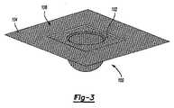
図3は、本発明の教示による実例となる造形中間品形体の斜視図である。 FIG. 3 is a perspective view of an illustrative shaped intermediate product form in accordance with the teachings of the present invention.
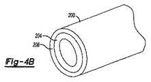
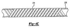
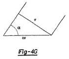
図4A〜4Gは本発明の教示によるパイプ構造を示す。 4A-4G illustrate a pipe structure in accordance with the teachings of the present invention.
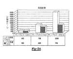
図5A及び5Bは本発明の教示によって得られる比較データ例を示す。 Figures 5A and 5B show example comparative data obtained by the teachings of the present invention.
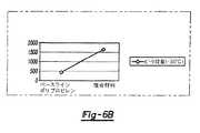
図6A及び6Bは本発明の教示によって得られるデータ例を示す。 6A and 6B show example data obtained by the teachings of the present invention.
第1の特定の態様において、本発明の方法は、中間品形体(intermediate form)の製造に関し、a)第1の熱可塑性材料からなり且つ隣接部分又は内部部分(例えば内部延伸部分)の溶融前に溶融可能な表面部分を有する少なくとも1つの長尺部材(elongated member)を用意し;そしてb)前記長尺部材を、互いに概ね自由に移動可能な複数の反復構造単位を含むことができる中間品形体の形に加工する工程を含む。前記中間品形体は、加工によって実質的に平滑で、しわのない造形完成品を形成することができる。一般に、全ての例において必要とは限らないが(本明細書中のミクロ層の教示の場合のように)、長尺部材は、配向(oriented)ポリオレフィン、特に、本発明の教示に従って加工できる、その初期形態を実質的に保留するものを含むものとする。 In a first particular embodiment, the method of the invention relates to the production of an intermediate form, a) consisting of a first thermoplastic material and prior to melting adjacent or internal parts (eg internal stretched parts) Providing at least one elongated member having a meltable surface portion; and b) an intermediate product that may include a plurality of repeating structural units that are generally freely movable relative to each other. Including the step of processing into the shape of the feature. The intermediate product form can be formed into a finished product that is substantially smooth and free of wrinkles. In general, although not necessary in all examples (as in the teachings of microlayers herein), the elongate member can be processed in accordance with the oriented polyolefin, particularly the teachings of the present invention, Including those that substantially hold their initial form.
別の特定の態様において、本発明の方法は、中間品形体を用いた物品の製造に関する。従って、その態様においては、加工工程は、少なくとも1つの長尺部材と隣接部分(例えば隣接延伸部分)より前に溶融可能な表面部分を有する第1の熱可塑性材料の複数の反復構造単位とを含む三次元中間品形体を団結及び造形し(例えば、単一操作で同時に又は複数の操作で連続的に);団結及び造形した前記中間品形体を成形型キャビティ中に入れ;第2の熱可塑性材料を前記成形型キャビティに導入し;そして成形型キャビティから、団結させた前記中間品形体及び前記第2の熱可塑性材料を含む強化複合物品を突出す工程を含む。また、第2の熱可塑性材料を成形型キャビティ中に導入する工程の間に部分団結を実施することも可能である。この実例となる態様は、前記の第1の実例となる態様と組合せて又はそれとは別個に実施できることは言うまでもない。従って、単一の製造業者が中間品形体とそれから得られる物品を製造することもできるし、或いは異なる製造業者がそれぞれを製造することもできる(例えば、材料供給業者が中間品形体を物品製造業者に供給する)可能性がある。更に、中間品形体の団結を除外して前記工程を実施してから、第2の熱可塑性材料を成形型キャビティ中に導入できる可能性もある。本明細書中の教示に従って製造される典型的な物品は、前記物品の長尺部材部分の高度の形態保留の結果として、優れた耐衝撃性及び関連特性(特に、材料の独特の選択若しくは組合せ及び/又は加工条件の使用によるその能力による)を示すので有利であろう。 In another specific embodiment, the method of the present invention relates to the manufacture of an article using an intermediate product form. Thus, in that aspect, the processing step comprises at least one elongate member and a plurality of repeating structural units of a first thermoplastic material having a meltable surface portion prior to an adjacent portion (eg, an adjacent stretched portion). Uniting and shaping a three-dimensional intermediate product form comprising (for example, simultaneously in a single operation or continuously in a plurality of operations); placing the united and shaped intermediate product form into a mold cavity; a second thermoplastic Introducing a material into the mold cavity; and projecting from the mold cavity a reinforced composite article comprising the consolidated intermediate form and the second thermoplastic material. It is also possible to perform partial unity during the process of introducing the second thermoplastic material into the mold cavity. It will be appreciated that this illustrative aspect can be implemented in combination with or separately from the first illustrative aspect described above. Thus, a single manufacturer can produce the intermediate product form and the article resulting therefrom, or different manufacturers can each produce it (eg, a material supplier can provide an intermediate product form to the product manufacturer). To supply). Furthermore, it is possible that the second thermoplastic material can be introduced into the mold cavity after performing the above steps, excluding the consolidation of the intermediate product features. A typical article manufactured in accordance with the teachings herein has excellent impact resistance and related properties (particularly a unique selection or combination of materials) as a result of the high degree of shape retention of the elongated member portion of the article. And / or depending on its ability to use processing conditions).
示されるように、本発明の種々の態様は、長尺部材材料に比較的高度の形態保持を生じる(その初期延伸時であって加工による複合物品の形成前における初期形態と比較して)を、材料の独特の組合せ、加工工程又は両者の発見に基づく。このように、本発明の教示は、得られる複合物品における、耐衝撃性のような性質の有益な保持を有利に可能にする。 As shown, the various aspects of the present invention result in a relatively high degree of shape retention in the elongate member material (as compared to the initial shape at the time of its initial stretching and prior to the formation of the composite article by processing). Based on the discovery of a unique combination of materials, processing steps or both. Thus, the teachings of the present invention advantageously allow beneficial retention of properties such as impact resistance in the resulting composite article.
本明細書中の教示は、複合材料の分野において有用な、特に、複合物品の形成のために団結され且つ場合によっては造形及び加工される(例えば、限定的ではないが、オーバーモールドされる)ことができる長尺部材として有用な材料の新規組合せを扱うことがわかるであろう。 The teachings herein are useful in the field of composite materials, particularly united and optionally shaped and processed (eg, but not limited to overmolded) to form composite articles. It will be appreciated that the novel combination of materials useful as an elongate member can be handled.
本明細書中の教示からわかるように、ポリオレフィン材料との関連で種々の態様を示すが、教示はそのように限定するものではない。本発明が提供する特定の進歩には、複合材料の分野において独特の適用可能性を有する特定のポリオレフィン材料の組合せの認識が含まれる。詳細には、本発明の一態様は、隣接ポリプロピレン層より低い融点を有するプロピレン系コポリマー(例えば、プロピレン−エチレンコポリマー、プロピレン−α−オレフィンコポリマー、それらの混合物又はその他)の、多層長尺部材として、特に延伸ポリプロピレン層としての使用を認めることを前提としている。本明細書中に教示したように加工して製品を形成すると、得られる材料(特に延伸ポリプロピレン層)は、従来の材料を用いてこれまで実現できなかった程度の、初期延伸状態からの形態保持性を示す。従って、本発明の態様は、約3〜25重量%(例えば、5〜15重量%)のエチレン含量、約50〜135℃の融解範囲及び約8〜約325MPa又はそれ以上(例えば、少なくともら約375MPa)の曲げ弾性率を有するプロピレン−エチレンコポリマー並びにプロピレン系ポリマーのようなポリオレフィンを含む第2の熱可塑性材料の使用を前提とする。このようなプロピレン−エチレンコポリマーは、約40〜90のショアーA硬度、約1.5〜約4の分子量分布及び少なくとも約0.3g/10分のメルトフローレート、又はそれらの任意の組合せを有することができる。 As will be appreciated from the teachings herein, various aspects are shown in the context of polyolefin materials, but the teachings are not so limited. Particular advancements provided by the present invention include the recognition of specific polyolefin material combinations that have unique applicability in the field of composite materials. Specifically, one aspect of the present invention is as a multilayer elongate member of a propylene-based copolymer (eg, propylene-ethylene copolymer, propylene-α-olefin copolymer, mixtures thereof, or the like) having a lower melting point than the adjacent polypropylene layer. In particular, it is assumed that the use as a stretched polypropylene layer is permitted. When processed to form a product as taught herein, the resulting material (especially a stretched polypropylene layer) retains its shape from an initially stretched state that has not previously been achieved using conventional materials. Showing gender. Thus, embodiments of the present invention have an ethylene content of about 3-25% by weight (eg, 5-15% by weight), a melting range of about 50-135 ° C. and about 8 to about 325 MPa or more (eg, at least about Suppose the use of a second thermoplastic material comprising a propylene-ethylene copolymer having a flexural modulus of 375 MPa) and a polyolefin such as a propylene-based polymer. Such propylene-ethylene copolymers have a Shore A hardness of about 40-90, a molecular weight distribution of about 1.5 to about 4 and a melt flow rate of at least about 0.3 g / 10 minutes, or any combination thereof. be able to.
使用できるプロピレン系ポリマーの一例は一般的にアイソタクチックであり、比較的に堅い。例えば、それは、約1000Mpa超の(更に限定すると約2000Mpa超の(例えば約2500Mpa又はそれ以上の))1%割線曲げ弾性率、約70%超の(例えば約85%超の)アイソタクチックペンタアド/トリアド比又は両者を有するポリプロピレンホモポリマーであることができる。更に、このようなポリプロピレンは典型的には、約160℃超の(例えば約165℃超の)ピーク融解温度、少なくとも約30%の(より限定すると少なくとも約50%又は更には70%の)結晶化度又は両者を有するであろう。 An example of a propylene-based polymer that can be used is generally isotactic and relatively stiff. For example, it has a 1% secant flexural modulus of greater than about 1000 Mpa (more limited to greater than about 2000 Mpa (eg, about 2500 Mpa or more)), an isotactic penta of greater than about 70% (eg, greater than about 85%). It can be a polypropylene homopolymer having an ad / triad ratio or both. Further, such polypropylene typically has a peak melting temperature of greater than about 160 ° C. (eg, greater than about 165 ° C.), at least about 30% (more specifically, at least about 50% or even 70%) crystals. Will have a degree or both.
本明細書中の教示はまた、前記ポリマーと又は本明細書中に教示した他のポリマーとの併用に関して、任意の、非移行性加工助剤又は表面改質剤を長尺部材材料の約10重量%未満の量で使用することによって有利な結果が得られる可能性があるという認識を前提とする。一例として、非移行性加工助剤又は表面改質剤としては、シリコーン樹脂(例えば高分子量シリコーン、例えば、ジメチルシロキサンのようなアルキルシロキサン)、ポリオレフィン、ハロゲン化ポリマー又はそれらの任意の組合せから選ばれた助剤を挙げることができる。 The teachings herein also include optional, non-migratory processing aids or surface modifiers in combination with the polymer or other polymers taught herein about 10% of the elongated member material. It is premised on the recognition that advantageous results may be obtained by using less than% by weight. As an example, the non-migratory processing aid or surface modifier may be selected from silicone resins (eg, high molecular weight silicones, eg, alkylsiloxanes such as dimethylsiloxane), polyolefins, halogenated polymers, or any combination thereof. Auxiliaries can be mentioned.
材料の新規組合せに関して、本明細書中の教示は、地球物理的繊維材料(geophysical textile material)(例えばポリオレフィン地球物理的繊維素材)を内部に使用することによる複合材料の二次加工への予想外のアプローチを明確にする。例えば、このような方法の1つは、地球物理的繊維素材を含む中間品形体を提供し、そして前記中間品形体に熱可塑性材料をオーバーモールドする工程を想定する。場合によっては、前記の非移行性加工助剤又は表面改質剤を使用できる。 With regard to new combinations of materials, the teachings herein are unexpected for the secondary processing of composite materials by using geophysical textile materials (eg, polyolefin geophysical fiber materials) internally. Clarify the approach. For example, one such method envisions providing an intermediate product form comprising a geophysical fiber material and overmolding a thermoplastic material into the intermediate product form. In some cases, the non-migratory processing aids or surface modifiers described above can be used.
本明細書中の教示はまた、本発明が、それぞれがポリマーを含む少なくとも4層の積み重なった層を有する長尺部材を特徴とする実施態様に関し、各層は、約50ミクロンより薄い(より典型的にはそれよりかなり薄く、例えば場合によっては約5ミクロンより薄い場合すらある)厚さを有し、また、各層は、その隣接層に比較して、組成、結晶化度、分子配向性、分子量、溶融速度、ピーク融解温度、ガラス転移ピーク、結晶化温度、シール開始温度、軟化点、分子量分布又それらの任意の組合せから選ばれた少なくとも1つの特性において異なる。 The teachings herein also relate to embodiments in which the invention features elongate members having at least four stacked layers each comprising a polymer, each layer being thinner than about 50 microns (more typically Each layer is much thinner (eg, even less than about 5 microns in some cases) and each layer has a composition, crystallinity, molecular orientation, molecular weight compared to its adjacent layers. , Melting rate, peak melting temperature, glass transition peak, crystallization temperature, seal initiation temperature, softening point, molecular weight distribution, or any combination thereof, differing in at least one characteristic.
1つのアプローチにおいては、長尺部材の少なくとも1層の又は場合によっては各層のポリマーは、プロピレン系ポリマー(例えばアイソタクチックポリプロピレンホモポリマーのようなポリプロピレンホモポリマー)であるものとする。例えば、層の1つ若しくはそれ以上(又は更には全て)がポリプロピレンを用いることができる。また、少なくとも1層のポリマーがエチレンを含むことも可能である。少なくとも2層の隣接層のポリマーがエチレン(例えばプロピレン−エチレンコポリマー、線状低密度ポリエチレン、高密度ポリエチレン又はそれらの任意の混合物から選ばれる)を含むこともできる。各隣接層のポリマーはポリエチレンを含むことができる。典型的には、少なくとも2層の隣接層のポリマーはそれぞれ、少なくとも約5℃だけ異なるピーク融解温度を有する。 In one approach, the polymer of at least one layer or possibly each layer of the elongate member is a propylene-based polymer (eg, a polypropylene homopolymer such as an isotactic polypropylene homopolymer). For example, one or more (or even all) of the layers can use polypropylene. It is also possible for at least one polymer layer to contain ethylene. The at least two adjacent layer polymers may also comprise ethylene (eg, selected from propylene-ethylene copolymers, linear low density polyethylene, high density polyethylene, or any mixture thereof). The polymer in each adjacent layer can include polyethylene. Typically, each of the at least two adjacent layer polymers has a peak melting temperature that differs by at least about 5 ° C.
連結層(tie−in layer)又は中間結合剤層(この使用は、本明細書中に教示したミクロ層にのみ限定せず、開示した任意の複数の多層構造に用いることもできる)のような添加剤又は他の機能材料を積み重なった層の少なくとも2層の間に使用することができる。これらの材料はまた、層のうち少なくとも1層の露出面上に配置された前記の非移行性加工助剤又は表面改質剤を含むこともできる。 Such as a tie-in layer or an intermediate binder layer (this use is not limited to the microlayers taught herein, but can also be used in any of the disclosed multilayer structures) Additives or other functional materials can be used between at least two of the stacked layers. These materials can also include the non-migratory processing aids or surface modifiers disposed on the exposed surface of at least one of the layers.
本出願の明細書全体に開示した材料、例えば、前述のプロピレン−エチレンコポリマー、アイソタクチックポリプロピレンホモポリマー又はそれらの組合せの使用に関連して本明細書中に示したが、本発明におけるミクロ層の進歩はこのような材料のみに限定しない。以下のような種々の他の材料の組合せも可能である:例えば、ポリオレフィンを含む第1のポリマー材料とポリアミドを含む第2のポリマー材料;ポリオレフィンを含む第1のポリマー材料とポリエステルを含む第2のポリマー材料;ポリアミドを含む第1のポリマー材料とポリエステルを含む第2のポリマー材料;又は更には、1種のポリエステルを含む第1のポリマー材料と別種のポリエステルを含む第2ポリマー材料。 Although indicated herein in connection with the use of materials disclosed throughout the specification of this application, such as the aforementioned propylene-ethylene copolymers, isotactic polypropylene homopolymers, or combinations thereof, the microlayers of the present invention The progress is not limited to such materials. Various other material combinations are also possible, for example: a first polymeric material comprising a polyolefin and a second polymeric material comprising a polyamide; a first polymeric material comprising a polyolefin and a second comprising a polyester A first polymer material comprising polyamide and a second polymer material comprising polyester; or, further, a first polymer material comprising one polyester and a second polymer material comprising another polyester.
本明細書中の教示からわかるように、本発明は多くの異なる用途において有用である。1つの好ましい用途は、本発明の教示を複合材料パイプの製造に適用することを意図する。要約すると、本発明の教示は、コアパイプを用意し;前記コアパイプ(例えばポリマー製の)に、第1の熱可塑性材料及び第2の熱可塑性材料からなる少なくとも1巻きの熱可塑性長尺部材を含む中間品形体を被覆し;前記中間品形体を団結させ;そして場合によっては、中間品形体を含むコアパイプを保護するために、コアパイプ及び中間品形体の少なくとも一部分の上に外被(jacket)を適用する工程を含む、複合材料パイプの製造方法を意図する。 As can be seen from the teachings herein, the present invention is useful in many different applications. One preferred application is intended to apply the teachings of the present invention to the manufacture of composite pipes. In summary, the teachings of the present invention provide a core pipe; the core pipe (e.g., made of polymer) includes at least one turn of an elongate thermoplastic member comprising a first thermoplastic material and a second thermoplastic material. Coating intermediate product form; uniting said intermediate product form; and, optionally, applying a jacket over at least a portion of the core pipe and intermediate product form to protect the core pipe containing the intermediate product form A method of manufacturing a composite pipe, comprising the steps of:
本明細書の教示から明らかなように、限定するものではないが、本発明の態様はまた、材料自体及びそれらの加工された形態の特性に加えて、本明細書中に記載した材料を用いて製造された物品、更には具体的な、このような物品の製造方法、このような物品の使用方法に関する。 As will be apparent from the teachings herein, aspects of the invention may also be used with the materials described herein in addition to the properties of the materials themselves and their processed forms. In addition, the present invention relates to a method for manufacturing such an article and a method for using such an article.
長尺部材及び中間品形体
最初に本発明の中間品形体に目を向けると、一般に、これらの中間品形体は、少なくとも1種の熱可塑性材料を含む組成を有する少なくとも1つの長尺部材を含む。「長尺部材」とは、一般に、その寸法の1つ(例えば長さ)が少なくとも1つの他の寸法(例えば幅、高さ、厚さ又は直径)よりも長い、特に、ここでは長尺部材の長さが幅又は高さよりもかなり大きい(例えば、少なくとも約10倍又はそれ以上大きい)部材を意味する。従って、本発明の長尺部材は、繊維、ロッド、コード、糸、テープ、フィラメント、ストラップ又はそれらの任意の組合せから選ばれた部材を含むことができるが、それらに必ずしも限定するものではない。前記からわかるように、多くの態様において、フィルムも、「長尺部材」の意味の範囲内と考えることができる。ホイスカー又は小板のような小規模部材も可能な場合がある。「長尺部材」は本明細書中では広範に考えるが、長尺部材の特に好ましい形態は、糸、テープ、繊維及びフィラメントの1つ又はそれ以上を含むことを認識すべきである。非常に好ましい長尺部材は、テープの形態である。Elongate Member and Intermediate Product Form Turning first to theintermediate product form of the present invention, these intermediate product forms generally include at least one elongate member having a composition that includes at least one thermoplastic material. . An “elongate member” generally means that one of its dimensions (eg length) is longer than at least one other dimension (eg width, height, thickness or diameter), in particular here an elongate member Means a member whose length is significantly greater than the width or height (eg, at least about 10 times or more). Accordingly, the elongate member of the present invention can include, but is not necessarily limited to, members selected from fibers, rods, cords, threads, tapes, filaments, straps, or any combination thereof. As can be seen from the foregoing, in many embodiments, the film can also be considered within the meaning of “long member”. Small scale members such as whiskers or platelets may be possible. While “elongate members” are considered broadly herein, it should be recognized that particularly preferred forms of elongate members include one or more of yarns, tapes, fibers and filaments. A highly preferred elongate member is in the form of a tape.
更に、本発明の長尺部材は典型的には、初期形態、特に初期配向状態を得るために加工されている(例えば、本明細書中に明記した割合によるなどして、一軸延伸され、二軸延伸され又は他の方法で延伸されている)と理解すべきである。本明細書中に開示された内容を用いて得ることができる多くの独特の利点には、加工終了時に、特に完成品において、長尺部材内で初期形態を実質的に保存できることがある。従って、例えば、加工時に、長尺部材の分子配向性は、その初期状態から実質的に保存される(例えば、長尺部材の初期配向性の少なくとも約50%、より好ましくは75%が残る)。 Further, the elongate members of the present invention are typically processed to obtain an initial morphology, particularly an initial orientation state (eg, uniaxially stretched, such as by the proportions specified herein, It should be understood that it is axially stretched or otherwise stretched). Many unique advantages that can be obtained using the content disclosed herein include the ability to substantially preserve the initial form within the elongated member at the end of processing, particularly in the finished product. Thus, for example, during processing, the molecular orientation of the elongated member is substantially preserved from its initial state (eg, at least about 50%, more preferably 75% of the elongated member's initial orientation remains). .
長尺部材の寸法は、典型的には、部材を手で取り扱うことを可能にするようなものであることができるであろう。しかし、より詳細には、長尺部材は、中間品形体に加工するために機械で取り扱えるような寸法にする。例えば、本発明の1つの具体例は、約5cm以下、より限定すると約1cm以下、更に限定すると約0.5cm以下、更に限定すると約1mm以下の厚さ、幅又は直径を有する、糸、テープ、繊維又はフィラメントのような長尺部材を想定する。例えば、1つのアプローチは、幅が5mm未満で且つ厚さが1mm未満、より限定すると0.5mm未満(例えば約0.01〜0.25mm)である、糸、テープ、繊維又はフィラメントのような長尺部材を使用することである。言うまでもなく、中間品形体は、それぞれが厚さ、幅又は両者において異なる複数の長尺部材を含むことができる可能性がある。例えば、織られた形態の経糸及び緯糸長尺部材はそれぞれ、厚さ、幅又はその両者が異なることができる。更に、本発明においてフィルムを長尺部材として用いる場合には、それらはかなり大きいことができる(例えば、場合によっては幅が少なくとも約5mで、長さが少なくとも約10、20又は更には40m)。 The dimensions of the elongate member could typically be such that the member can be handled by hand. More specifically, however, the elongate member is sized to be machined for processing into an intermediate product form. For example, one embodiment of the present invention is a thread, tape having a thickness, width or diameter of about 5 cm or less, more specifically about 1 cm or less, more specifically about 0.5 cm or less, and more specifically about 1 mm or less. Suppose elongate members such as fibers or filaments. For example, one approach is such as a thread, tape, fiber or filament that is less than 5 mm in width and less than 1 mm in thickness, more specifically less than 0.5 mm (eg, about 0.01-0.25 mm). It is to use a long member. Of course, the intermediate feature may include a plurality of elongate members, each differing in thickness, width, or both. For example, the warp and weft long members in woven form can each differ in thickness, width or both. Further, when films are used as elongate members in the present invention, they can be quite large (eg, in some cases at least about 5 meters wide and at least about 10, 20, or even 40 meters long).
典型的な長尺部材は断面が連続的である。しかし、長尺部材の長さに沿って少なくとも一部分は、長尺部材は全面的に緻密化され、部分的に緻密化され(例えば、発泡され)、孔をあけられ、波形にされ、撚られ、又はそれらの任意の組合せであることができる可能性がある。長尺部材は、長尺部材の寸法に沿って異なる性質又は他の特性を有することができる。 A typical elongate member is continuous in cross section. However, at least in part along the length of the elongate member, the elongate member is fully densified, partially densified (eg, foamed), perforated, corrugated, and twisted. , Or any combination thereof. The elongate member can have different properties or other characteristics along the length of the elongate member.
言うまでもなく、本発明の教示は広範囲に及び、取り上げた実施態様に必ずしも限定する必要はない。例えば、本発明は、長尺部材としての用途を有する種々の異なる材料を教示しているが、このような長尺部材の特定用途にはこだわらない。しかし、ポリマー強化複合材料の教示との関連においては特に、本発明の長尺部材の1つ又はそれ以上は普通は、組み立てて、織物、編物又は複数の反復構造単位がある他の形態(これらに限定するものではない)のような中間品形体にする(例えば、経糸及び緯糸が複数の長尺部材を使用する)。しかし、反復単位は、巻構造の個別の巻物のように単純であることができる(このような構造は単一の長尺部材を用いることによって可能である)。 Of course, the teachings of the present invention are broad and need not be limited to the embodiments discussed. For example, the present invention teaches a variety of different materials having applications as elongate members, but is not particular about the particular application of such elongate members. However, particularly in the context of the teaching of polymer reinforced composites, one or more of the elongate members of the present invention are usually assembled into a woven, knitted or other form with multiple repeating structural units (these (For example, warp and weft use a plurality of long members). However, the repeating unit can be as simple as an individual roll of a wound structure (such a structure is possible by using a single elongate member).
従って、長尺部材を形成後、それは、織られた形態、巻繊の形態、編まれた形態、編組された形態、ランダムに分散された形態又はそれらの任意の組合せから選ばれた1つのような中間品形体を作るために加工する。中間品形体はまた、包むか又は他の方法で塗装若しくは被覆することもできる。本明細書中で言及するように、中間品形体は典型的には複数の反復構造単位を含む。これらの構造単位の例を図2Aに示す。例えば、中間品形体10は、図2Aのバスケット織、別の平織、綾織(例えば、ヘリンボン、ツイード、千鳥格子、格子縞又は他の綾織)、レース、繻子織又はそれらの任意の組合せのようなパターン14を規定するように配置された複数の反復構造単位12を含むであろう。特定の織物組織の例としては、柄経糸長尺部材を緯糸長尺部材上に、次いで緯糸長尺部材下に1/1〜14/2(例えば2/1、2/2、3/1又はその他)の経糸/緯糸比で走行している織物組織が挙げられる。織物組織の更に特定の例としては、限定するものではないが、2/1綾織、2/2綾織、千鳥サテン(crowfoot satin)、2/2バスケット織、5Hサテン、8−Hサテン又はその他が挙げられる。従って、明らかなように、中間品形体の個別の構造単位は、互いに対して任意の多数の可能な配置で配置することができる。例えば、図2A及び2Bに示されるように、重なり合う単位は互いに概ね垂直であることができる。しかし、織物組織の他の角度も要望通りに使用できる。一般に、(経糸長尺部材)対(緯糸長尺部材)の重量比は約90:10〜約40:60、より好ましくは約70:30〜約45:55(例えば約50:50)の範囲である。 Thus, after forming the elongate member, it is like one selected from a woven form, a wound fiber form, a knitted form, a braided form, a randomly dispersed form, or any combination thereof. To produce a simple intermediate product shape. The intermediate product form can also be wrapped or otherwise painted or coated. As referred to herein, the intermediate form typically comprises a plurality of repeating structural units. Examples of these structural units are shown in FIG. 2A. For example, the
実例となる経糸及び緯糸の範囲を前に開示したが、その他の範囲も満足のいく結果を提供できる可能性がある。例えば、単位面積当たりの経糸長尺部材の平均数は、同一面積中の緯糸長尺部材の数と同一であることができる。それぞれの数は互いに対して変化することができる可能性がある。例えば、単位面積当たりの経糸長尺部材及び緯糸長尺部材の平均数は10%又はそれ以下だけ異なることができる(例えば、4cm2の範囲内に、18本の経糸部材と20本の緯糸部材が存在することができる)。それらは、これより大きい割合で、例えば、少なくとも20%又は更には少なくとも50%異なることもできる(例えば、4cm2の面積内に、10本の経糸部材と20本の緯糸部材が存在することができる)。Illustrative warp and weft ranges have been previously disclosed, but other ranges may provide satisfactory results. For example, the average number of long warp members per unit area can be the same as the number of long weft members in the same area. Each number may be able to vary with respect to each other. For example, the average number of warp long members and weft long members per unit area may differ by 10% or less (for example, 18 warp members and 20 weft members within a range of 4 cm2. Can exist). They can also differ by a greater percentage, for example at least 20% or even at least 50% (for example, there may be 10 warp members and 20 weft members in an area of 4 cm2. it can).
また、経糸長尺部材と緯糸長尺部材との間と同様に、長尺部材の厚さ、幅又は両者も実質的に同じであることができ、従ってそれらはせいぜい約10%しか異ならないことができる可能性がある。しかし、経糸長尺部材と緯糸長尺部材との間と同様に、長尺部材の厚さ、幅又は両者は20%又はそれ以上異なることができる可能性もある。すぐ下に更に詳細に記載するが、中間品形体は複数の層を含むことができ、それらの層の少なくとも2層は他の層と比較して異なる織物組織特性を有することができることは前記からわかるであろう。 Also, as between a warp long member and a weft long member, the thickness, width, or both of the long member can be substantially the same, so that they differ by no more than about 10%. There is a possibility. However, as between the warp long member and the weft long member, the thickness, width, or both of the long member may be different by 20% or more. As described in more detail immediately below, it can be seen from the foregoing that an intermediate product form can include a plurality of layers, at least two of which can have different fabric texture characteristics compared to the other layers. You will understand.
一体型長尺部材及び地球物理的繊維素材
以下の解説から示されるように、本発明の教示に従って有用な長尺部材は実質的に均質な構造であることができる、即ち、組成が全体にわたって同一である一体構造であることができる。それらはまた、幅、厚さ又は直径を横切って組成が変動することができ、例えば、それは多層構造によって実現できる。前者に関しては、一体型長尺部材構造の巻物が可能であるが、より普通には、一体型長尺部材は、地球物理的繊維素材(geophysical textile)として一般に知られる材料のように、織られた形態であろう。Integral elongate member and geophysical fiber material As will be shown from the discussion below, elongate members useful in accordance with the teachings of the present invention can be of a substantially homogeneous structure, i.e., the same composition throughout. It can be a monolithic structure. They can also vary in composition across width, thickness or diameter, for example it can be realized by a multilayer structure. With respect to the former, scrolls with an integral long member structure are possible, but more commonly the integral long member is woven, such as a material commonly known as a geophysical textile material. It would be a form.
実際には、本発明の多くの独特の特徴の中には、前に言及した一体材料、例えば、前記地球物理的繊維素材を有効活用できることがある。これらの材料は現在普通は多くの土木用途を有する(本発明の教示はそこまでは続けられていないが)。この土木用途は、例えば、砂防/土壌保持、シルトフェンス、造園、補強、分離(例えば、舗装のため)、排水及び他の用途の1つ又はそれ以上である。かなり多くの場合、地球物理的繊維素材は、比較的高い二方向性の強度及び剛性を示し、団結させることができないために若干の透過性、誘電率又は両者を示す場合がある繊維織物を含む。地球物理的繊維素材の性質は、広範囲にわたって変化できる。一例として、地球物理的繊維素材は、少なくとも約0.3kN、より限定すると約0.5〜約3kNの範囲の掴み引張強さ(grab tensile strength)(ASTM D4632による)及び少なくとも10%、例えば約15%(50%又はそれ以上のレベルも可能である)の掴み引張強さ伸び(grab tensile strength elongation)(ASTM D4632による)を示すことが可能な場合がある。地球物理的繊維素材は、少なくとも約1000kPa、より限定すると約2000〜10,000kPa(例えば約3000〜7000kPa)のMullen破裂強さ(ASTM D3786による)、及び少なくとも0.20kN、より限定すると約0.25〜約0.80kNの範囲の衝撃穴あけ強さ(puncture strength)(ASTM D4833による)を示す。市販の地球物理的繊維素材の例としては、ポリプロピレン布、例えば、Propex(登録商標)(Propex Fabrics(Georgia)製)の名称で提供される物、更にはDon & LowによってLOTREKの名称で、Mirafi(Ten Cate Nicolon)によってGEOLONの名称で、並びにUS Fabrics,Inc.及びLINQ Industrial Fabrics,Inc.のような他の製造供給元によって提供される地球物理的繊維素材が挙げられる。 In fact, among the many unique features of the present invention, it may be possible to make effective use of the previously mentioned monolithic material, such as the geophysical fiber material. These materials currently have many civil engineering applications (although the teachings of the present invention have not been continued so far). This civil engineering application is, for example, one or more of sabo / soil retention, silt fence, landscaping, reinforcement, separation (eg, for paving), drainage and other applications. Quite often, geophysical fiber materials include fiber fabrics that exhibit relatively high bi-directional strength and stiffness and may not be able to unite and thus exhibit some permeability, dielectric constant, or both . The properties of geophysical fiber materials can vary over a wide range. As an example, the geophysical fiber material may have a grab tensile strength (according to ASTM D4632) of at least about 0.3 kN, more specifically in the range of about 0.5 to about 3 kN, and at least 10%, for example about It may be possible to indicate a grab tensile strength elongation (according to ASTM D4632) of 15% (levels of 50% or higher are also possible). The geophysical fiber material is a Mullen burst strength (according to ASTM D3786) of at least about 1000 kPa, more specifically about 2000 to 10,000 kPa (eg about 3000 to 7000 kPa), and at least 0.20 kPa, more specifically about 0.00. It shows the puncture strength (according to ASTM D 4833) in the range of 25 to about 0.80 kN. Examples of commercially available geophysical fiber materials include polypropylene fabrics such as those provided under the name Propex® (manufactured by Propex Fabrics (Georgia)), and also under the name LOTREK by Don & Low, Mirafi (Ten Cate Nicolon) under the name GEOLON and US Fabrics, Inc. And LINQ Industrial Fabrics, Inc. Geophysical fiber materials provided by other manufacturers such as
本発明に従って有用な地球物理的繊維素材は1種又はそれ以上の熱可塑性樹脂(例えば、ポリエステル、ポリオレフィン又はそれらの組合せ)から二次加工することができることがわかるであろう。言うまでもなく、本明細書中に開示した種々の個別の熱可塑性材料は、地球物理的繊維素材の形態にすることができる。地球物理的繊維素材は普通は(しかし必ずしも必要ないが)延伸された部分を含む。典型的には、本発明において織られた地球物理的繊維素材を用いて製造される物品は、延伸部分、特に、その初期形態の実質的な保存を示す部分を含むように加工された(例えば、延伸された)長尺部材を含む。1つの好ましいアプローチは織られた地球物理的繊維素材の使用を意図するが、地球物理的繊維素材は織られていない(例えば、典型的にはニードルパンチ及び熱接着が施されたステープルファイバー、連続フィラメント又は両者から製造される)ことも可能である。地球物理的繊維素材は典型的には、スリットフィルム又は押出モノフィラメントなどから製造し、従って普通は、延伸された部分を含むように加工する。しかし、繊維素材は1種又はそれ以上のマルチフィラメントを組み込むことができる可能性がある。本発明の更に別の態様において、地球物理的繊維素材は、1種又はそれ以上の天然繊維、例えば、ジュート、ヘンプなどを含むことができる。 It will be appreciated that geophysical fiber materials useful in accordance with the present invention can be fabricated from one or more thermoplastic resins (eg, polyesters, polyolefins, or combinations thereof). Of course, the various individual thermoplastic materials disclosed herein can be in the form of a geophysical fiber material. Geophysical fiber materials usually (but not necessarily) include stretched portions. Typically, articles made using the geophysical fiber material woven in the present invention have been processed to include a stretched portion, particularly a portion that exhibits substantial preservation of its initial form (eg, A stretched elongate member. One preferred approach contemplates the use of woven geophysical fiber material, but the geophysical fiber material is not woven (eg, staple fibers typically subjected to needle punching and thermal bonding, continuous It is also possible to be manufactured from filaments or both. Geophysical fiber materials are typically manufactured from slit films or extruded monofilaments and so are typically processed to include stretched portions. However, the fiber material may be able to incorporate one or more multifilaments. In yet another aspect of the invention, the geophysical fiber material can include one or more natural fibers, such as jute, hemp, and the like.
本明細書中の解説からわかるように、地球物理的繊維材料は、本明細書中に開示した種々の実施態様に使用できる。一例として、限定的するものではないが、地球物理的繊維素材は、本発明の教示に従ってオーバーモールドすることができ;多層中間品形体中において1つ又はそれ以上の他の地球物理的繊維素材、多層の織られた若しくは巻かれた中間品形体又は両者と組合せることができ;本明細書中のホモポリマー又はコポリマーの1つ又は組合せを使用することができ;或いはそれらの組合せであることができる。 As can be seen from the discussion herein, geophysical fiber materials can be used in the various embodiments disclosed herein. By way of example, but not limitation, a geophysical fiber material can be overmolded in accordance with the teachings of the present invention; one or more other geophysical fiber materials, Can be combined with a multilayer woven or rolled intermediate form or both; one or a combination of the homopolymers or copolymers herein may be used; or may be a combination thereof it can.
多層長尺部材
ここで、長尺部材の他の態様のより詳細な解説に移ると、本明細書中に開示した技術への1つの普通のアプローチは、多層長尺部材の使用である。詳細には、多層長尺部材は普通、少なくとも第1の表面部分と、第1の部分に隣接する第2の部分を使用し、第1の部分と第2の部分とは組成、多分散度、形態、溶融速度又はそれらの任意の組合せにおいて異なる。例えば、1つの具体的なアプローチは、延伸隣接部分のような隣接部分の前に溶融することができる表面部分を有する、第1の熱可塑性材料からなる少なくとも1つの長尺部材を想定する。Multi-layer elongate member Turning now to a more detailed description of other aspects of the elongate member, one common approach to the techniques disclosed herein is the use of multi-layer elongate members. Specifically, multilayer elongate members typically use at least a first surface portion and a second portion adjacent to the first portion, the first portion and the second portion being composed, polydispersity , In form, melting rate or any combination thereof. For example, one specific approach envisions at least one elongate member of a first thermoplastic material having a surface portion that can be melted before an adjacent portion, such as an extended adjacent portion.
本発明の教示により、単一ポリマー(例えば、ポリマーA若しくはB単独、例えば、地球物理的繊維素材との関連で前述したもの)又は複数の隣接ポリマー[例えば、ポリマーA及びB−本明細書中ではA−B成分構造、例えば、A−B、A−B−A、A−B−C、A−B−C−Dなど又はそれらの任意の組合せ、例えば、A−B−D、A−B−C−B−D、A−C−B又はその他と称する(C及びDは、例えば、本明細書中のミクロ層の教示と共に見られるような更に他の可能なポリマーを意味するがこれらに限定されない)]を用いてテープのような長尺部材を作ることが可能になるので有利である。長尺部材内に異なるポリマーを用いる場合には、それらはそれぞれ同一組成であっても異なる組成であってもよい。それらは、同一の一般系のポリマー(例えば、ポリオレフィン)に由来するものであっても異なってもよい。それらは、1つの系内の同一特定型のポリマー(例えば、ポリプロピレン)に由来するものであってもよいが、重量平均分子量、多分散度、形態、溶融速度若しくは他の溶融特性又はそれらの任意の組合せのような一部の特性に関して互いに異なることができる。成分(例えば、A、B、C、D又は他の何らかの成分)の1つ又はそれ以上は必ずしもポリマーである必要はなく、添加剤又は他の機能材料であることができることを理解されたい。 In accordance with the teachings of the present invention, a single polymer (eg, polymer A or B alone, eg, as described above in connection with a geophysical fiber material) or a plurality of adjacent polymers [eg, polymers A and B—herein A-B component structure such as A-B, A-B-A, A-B-C, A-B-C-D, etc., or any combination thereof such as A-B-D, A- Referred to as B-C-B-D, A-C-B or others (C and D mean other possible polymers such as those found with the teachings of microlayers herein, for example. It is advantageous that a long member such as a tape can be made using the above. When different polymers are used in the elongate member, they may have the same composition or different compositions. They may be derived from the same general polymer (for example, polyolefin) or different. They may be derived from the same specific type of polymer (eg, polypropylene) within a system, but weight average molecular weight, polydispersity, morphology, melt rate or other melt properties or any of them May differ from each other with respect to some characteristics, such as combinations. It should be understood that one or more of the components (eg, A, B, C, D, or some other component) need not necessarily be a polymer, but can be an additive or other functional material.
最初に、典型的には、成分A及びBを含む材料(例えば、A−B−A長尺部材)において見られるような多層の実施態様に目を向けると、A及びB成分は、互いに層状に積み重ねられた関係で[例えば、図1A,並列(例えば、二成分材料)]又はコア/シース関係で(例えば図1B)配列する。B成分は少なくとも一方の面を露出する(例えば、図1Aは2つの露出面を示している)などして一部分だけ被覆することもできるし、或いはA成分によってその周囲を完全に被覆することもできる(図1Bのように)。図1Aの層状の実施態様はまた、丸みを帯びた縁又は表面を含むことができることがわかるであろう。通常、成分Bは長尺部材内部に位置し、成分Aよりも融点の高い材料である。従って、長尺部材の構造及び材料は、成分Aを成分Bの前に溶融することを可能にし、少なくとも成分B中において形態の実質的な保留を可能にするであろう。成分Bに対する成分Aの相対量は変動可能であることがわかるであろう。一部の用途においては、例えば、比較的小さい外層(例えば、A−B−A多層組合せのA層)を比較的大きい内層(B層)に適用することが可能である。他の用途は比較的大きい外層を用いることができる。例えば、A−B−A組合せに関して、それぞれの相対体積は約1:1:1〜1:35:1、より限定すると約1:10:1〜1:25:1、更に限定すると約1:15:1〜1:20:1(例えば1:17:1)の範囲であることができる。A−B芯鞘構造は同様な比率を用いることができるが、外層の1つに関する対応する数量の1つを除外する。例えば、1:1:1ではなく、比率は1:1となるであろう。 Initially, turning to a multi-layered embodiment as typically found in materials comprising components A and B (eg, A-B-A elongate member), the A and B components are layered together. In a stacked relationship [eg, FIG. 1A, side-by-side (eg, two-component material)] or a core / sheath relationship (eg, FIG. 1B). The B component can be partially covered by exposing at least one surface (for example, FIG. 1A shows two exposed surfaces), or the periphery can be completely covered by the A component. Yes (as in FIG. 1B). It will be appreciated that the layered embodiment of FIG. 1A can also include rounded edges or surfaces. In general, component B is a material that is located inside the elongated member and has a higher melting point than component A. Thus, the structure and material of the elongate member will allow component A to melt prior to component B and allow substantial retention of form at least in component B. It will be appreciated that the relative amount of component A relative to component B can vary. In some applications, for example, a relatively small outer layer (eg, A layer of an ABA multi-layer combination) can be applied to a relatively large inner layer (B layer). Other applications can use a relatively large outer layer. For example, for the A-B-A combination, the relative volume of each is about 1: 1: 1 to 1: 35: 1, more specifically about 1: 10: 1 to 1: 25: 1, and more preferably about 1: It can range from 15: 1 to 1: 20: 1 (eg, 1: 17: 1). A B-B sheath structure can use similar ratios, but excludes one of the corresponding quantities for one of the outer layers. For example, rather than 1: 1: 1, the ratio will be 1: 1.
前述のように、これらの成分(例えば、A−B−A多層長尺部材)を用いて製造された長尺部材(例えば同時押出テープ)は好ましくは成分Aを約1〜20重量%及び成分Bを約80〜99重量%含む。このような相対比率は、本発明の教示に係る多数の種々の長尺部材に典型的であるが、限定するものと見なしてはならない。例えば、一部の用途に関しては、長尺部材中において成分Bに対してより大きい比率の成分Aを使用することも可能であり、本明細書中の教示に従って良好な結果を得ることができる。例えば、成分B(例えば、ポリプロピレンのホモポリマーのようなポリプロピレンを含むポリマー)の量は全重量の約50%未満(例えば、全重量の約45重量%未満、又は場合によっては全重量の約10〜約45重量%、又は更に限定すると全重量の約20〜約40重量%)であることができる。 As noted above, elongate members (e.g., coextruded tapes) made using these components (e.g., ABA multi-layer elongate members) preferably contain about 1-20 wt. About 80 to 99% by weight of B is contained. Such relative proportions are typical for a number of different elongated members according to the teachings of the present invention, but should not be considered limiting. For example, for some applications, it is possible to use a greater ratio of component A to component B in the elongate member, and good results can be obtained in accordance with the teachings herein. For example, the amount of component B (eg, a polymer comprising polypropylene, such as a homopolymer of polypropylene) is less than about 50% of the total weight (eg, less than about 45% by weight of the total weight, or in some cases about 10% of the total weight). To about 45% by weight, or more specifically, about 20 to about 40% by weight of the total weight).
一般に、長尺部材が少なくとも成分A及び成分Bを含む場合には、典型的には、成分A及びBの融点(ある温度範囲にわたって起こる場合がある)は異なり、成分Aの融点(即ち、融解範囲を有する材料に関してはピーク融解温度)は成分Bの融点よりも低い。更に、融点が高い方の材料は典型的には少なくとも部分的に延伸させる(例えば、一軸延伸又は二軸延伸させる)。比較した融点はわずか約5℃しか異ならないこともできるが、より典型的には、少なくとも約10℃、より好ましくは少なくとも約20℃異なり、1つの具体例においては少なくとも約25℃(例えば約30℃)又はそれ以上も異なることができる。例えば、限定するものではないが、成分Aは約130℃の融点を有することができ、且つ成分Bは約160℃超の融点を有することができる。融点に関する温度の拡大の結果として得られるのは、成分Aが流れて隣接材料と融合することができる加工ウィンドウを、冷却時における団結の達成のために実現できることである。その間に、成分Bの加工温度をその融点以下に保持することによって、成分Bがその初期形態をかなり劣化し且つその性質、例えば、長尺部材の全体的な高い曲げ弾性率を損なうリスクを低下させることができる。その結果として、加工終了時に、特に完成品において、長尺部材内における初期形態の実質的な保持を実現できることによって更なる利益を実現できる。形態を保持できる他に、温度範囲の下端近くにおける団結は、長尺成分が弛緩又は収縮を起こす傾向が一般により少ないという更なる利点を有する。 In general, if the elongate member includes at least component A and component B, typically the melting points of components A and B (which may occur over a range of temperatures) are different and the melting point of component A (ie, melting) For materials having a range, the peak melting temperature) is lower than the melting point of component B. Further, the material with the higher melting point is typically at least partially stretched (eg, uniaxially or biaxially stretched). The compared melting points can differ by only about 5 ° C, but more typically differ by at least about 10 ° C, more preferably at least about 20 ° C, and in one embodiment at least about 25 ° C (eg, about 30 ° C). ° C) or more. For example, without limitation, Component A can have a melting point of about 130 ° C. and Component B can have a melting point greater than about 160 ° C. The result of the increase in temperature with respect to the melting point is that a processing window in which component A can flow and fuse with the adjacent material can be realized to achieve unity on cooling. In the meantime, by keeping the processing temperature of component B below its melting point, component B significantly degrades its initial morphology and reduces the risk of damaging its properties, for example, the overall high flexural modulus of long members. Can be made. As a result, further benefits can be realized by achieving substantial retention of the initial form within the elongated member at the end of processing, particularly in the finished product. In addition to being able to retain morphology, unity near the lower end of the temperature range has the further advantage that the long component is generally less prone to relax or shrink.
前述のように、解説のために選ばれる参照溶融特性温度は融点(例えば、ISO 11357−3に従って示差走査熱量測定法によって得られる)であることがわかる。一部の材料に関しては、融点は鮮明に規定されない場合がある(例えば、ある温度範囲にわたって現れるため)ことを理解すべきである。従って、このような材料に関しては、当業者ならば、融点への言及は一般にピーク融解温度を意味することがわかるであろう。更に、場合によっては、それぞれの成分に関して、材料の溶融特性の別の関連尺度、ガラス転移温度又はポリマー軟化温度、結晶化ピーク温度[例えば、国際出願公開番号第WO2004/033509号明細書(引用することによって本明細書中に組み入れる)に記載されたようなもの]、又は更にはシール開始温度[例えば、C.H.Stephens,B.C.Poon,A.R.Kamdar,S.Chum,P.Ansems,K.Swogger,A.Hiltner及びE.BaerによってIsothermal Crystallization Kinetics and Morphology of Polypropylenes and Propylene/Ethylene(P/E) Copolymers(2004年5月にSPE ANTEC Conference(Chicago,IL)において発表)に記載されたもの]で代用することによって、代わりの同様なアプローチを用いることがより都合よいこともある。As noted above, it can be seen that the reference melt characteristic temperature chosen for explanation is the melting point (eg, obtained by differential scanning calorimetry according to ISO 11357-3). It should be understood that for some materials, the melting point may not be sharply defined (eg, because it appears over a range of temperatures). Thus, for such materials, those skilled in the art will understand that reference to melting point generally means peak melting temperature. Further, in some cases, for each component, another relevant measure of the melting properties of the material, glass transition temperature or polymer softening temperature, crystallization peak temperature [eg International Application Publication No. WO 2004/033509 (cited Such as those described in US Pat. No. 6,036,048)], or even the seal initiation temperature [e.g. C.I. H. Stephens, B.M. C. Poon, A.M. R. Kamdar, S .; Chum, P.A. Ansems, K.M. Swogger, A.M. Hiltner and E.M.Announced by Baer in theIsolational Crystallization Kinetics and Morphology of Polypropylenes and Propylene / Ethylene (P / E) Co-Polymers (written by SPE ANTEC Conference in May 2004) It may be more convenient to use a similar approach.
従って、効果的には、一般に個々の成分A及びBの適切な溶融特性温度の望ましい広がり(例えば、ポリマーのこのような溶融特性温度における約5、10、20、25若しくは30℃又はそれ以上の差)を選択することによって、成分Bが成分Aに対してそれらの初期固体状態において有する増大した機械的性質を低下させることなく、成分Aの融合を行うことができる。 Thus, effectively, generally a desired spread of the appropriate melt characteristic temperature of the individual components A and B (eg, about 5, 10, 20, 25 or 30 ° C. or more at such melt characteristic temperature of the polymer or higher). By selecting (Difference), the fusion of component A can be effected without degrading the increased mechanical properties that component B has over component A in their initial solid state.
多層構造の1つの考えられる利点は、長尺部材のそれぞれの部分内において特性の差を生じる長尺部材を製造でき、その結果、長尺部材を個々の用途、個々の一連の加工条件又はそれらの組合せに正確に特化させることができることである。本明細書中の解説を見直すことによって明らかなように、有利な多層構造を得る方法は、追求される付随的な結果によって異なることができ、多層構造の実現には種々の手法を使用できる。例えば、1つ又はそれ以上の部分について、塗装、積層、接着、表面処理[例えば、大気処理(例えば、酸化など)、コロナ放電又は他のプラズマ処理]、溶射、イオン化、照射、粉体被覆、ホットメルト適用を行うか、又は別の方法によって他の部分への接合を行うことができる。別のアプローチにおいては、異なる部分を異なる熱処理、異なる歪処理又は他の加工条件に供することができる。更に別のアプローチにおいては、異なる部分を同時押出する。前記アプローチの組合せも使用できる。 One possible advantage of the multi-layer structure is that it is possible to produce elongate members that produce differences in properties within the respective portions of the elongate member, so that the elongate member can be used in an individual application, an individual set of processing conditions or those It is possible to specialize precisely in the combination of. As will be apparent by reviewing the discussion herein, the method of obtaining an advantageous multilayer structure can vary depending on the incidental results sought, and various approaches can be used to realize the multilayer structure. For example, for one or more parts, painting, laminating, bonding, surface treatment [eg, air treatment (eg, oxidation), corona discharge or other plasma treatment], thermal spraying, ionization, irradiation, powder coating, Hot melt application can be done, or bonding to other parts can be done by other methods. In another approach, different portions can be subjected to different heat treatments, different strain treatments, or other processing conditions. In yet another approach, different parts are coextruded. Combinations of the above approaches can also be used.
更に詳細には、典型的には、本発明の長尺部材は、フィルム(このフィルムは未延伸でもよいが、より典型的には一軸延伸、二軸延伸又は他の方法で延伸される)に由来する。例えば、非常に典型的なのは、長尺部材(特に、糸、テープ、繊維又はフィラメントのうち少なくとも1つから選ばれた長尺部材)は、溶融ポリマー(例えば、ポリマーの溶融温度の、例えば、種々のポリオレフィン又は他の熱可塑性樹脂の場合には約200〜240℃の)を、インフレーション法(blown film process)[例えば、国際出願公開番号第WO2005035598号明細書(引用することによって本明細書中に組み入れる)に記載されたような空冷インフレーション法]に供することによって、キャストフィルム若しくはシートによって(例えば、チルドロールを用いて、押出溶融ポリマーを急冷する)、又はフィルム若しくはシート押出によって(例えば、水浴を通すことによって)製造できることである。これらのアプローチの組合せも使用できる。次いで、フィルム又はシートを、適当な切断(cutting)操作、例えば、ソニックスリッティング(sonic slitting)、ホットナイフスリッティング(hot knife slitting)、それらの組合せ又はその他の方法を用いて、所定の幅に細長く切ることができる。スリットフィルムは次に、加熱相(例えば、熱板の使用による)又は延伸操作(場合によっては高温延伸のために延伸用オーブンを用いる)によって、所望のデニール(例えば、約1000〜約20,000、例えば、場合によっては約13,500超)及び重量(例えば、少なくとも約7g/デニール、場合によっては少なくとも約9g/デニール又はそれ以上、更に限定すると約10g/デニール超)に加工することができる。いくつかの実施態様に関しては、スリットフィルムは約60〜300のテックス特性(長さ約10kmのテープの重量)を有することができる。スリットフィルムはまた、最終製品中に後で使用するために、フィブリル化し且つボビンに巻き付けることができる。前記の全プロセスは典型的には連続法であるが、連続法である必要はない。 More particularly, the elongated member of the present invention is typically formed into a film (this film may be unstretched, but more typically is uniaxially stretched, biaxially stretched or otherwise stretched). Derived from. For example, very typically, an elongate member (especially an elongate member selected from at least one of yarns, tapes, fibers or filaments) is a molten polymer (e.g. In the case of polyolefins or other thermoplastic resins of about 200-240 ° C., a blown film process [eg, International Application Publication No. WO 2005035598 (incorporated herein by reference). Air-cooled inflation method as described in (incorporating)] by casting film or sheet (eg quenching the extruded molten polymer using chilled rolls) or by film or sheet extrusion (eg water bathing). That can be manufactured) The A combination of these approaches can also be used. The film or sheet is then brought to a predetermined width using a suitable cutting operation, such as sonic slitting, hot knife slitting, combinations thereof, or other methods. Can be cut into strips. The slit film is then subjected to the desired denier (eg, from about 1000 to about 20,000) by a heating phase (eg, by use of a hot plate) or a stretching operation (possibly using a stretching oven for high temperature stretching). For example, in some cases greater than about 13,500) and weight (eg, at least about 7 g / denier, in some cases at least about 9 g / denier or more, and more specifically, greater than about 10 g / denier). . For some embodiments, the slit film can have a tex characteristic of about 60-300 (the weight of a tape of about 10 km in length). The slit film can also be fibrillated and wound onto bobbins for later use in the final product. The entire process is typically a continuous process, but need not be a continuous process.
更なる特定例として、長尺部材(特に、糸、テープ、繊維及びフィラメントから選ばれた長尺部材)を形成するための他の可能なアプローチは、溶融モノマー(例えば、90〜230℃の融解温度の)をシート押出ダイ(例えば、Collin Teachline押出機)のような適当なダイ(場合によっては、テーパー開口部を有する)を用いた押出工程に供して(例えば、その後に、20〜40℃の温度の水浴を通す)、厚さ約10mm以下(より典型的には厚さ約1mm)のキャストシートを形成することができる。シートは約1〜20mm、より特別には約2〜10mm(例えば約5mm)の幅に細長く切り、約50〜70℃(例えば60℃)において1つ又はそれ以上の加熱オーブン中でゴデット間で約2〜10(例えば約5)又はそれ以上の延伸比まで延伸する。得られた糸、テープ、繊維又はフィラメントは次に更に1つ又はそれ以上の高温において(例えば約120℃超で、例えば、約140〜200℃(例えば約170℃)の温度で)少なくとも約2〜8(例えば約3.5)の1つ又はそれ以上の更なる延伸比で伸張して、所望の厚さ(例えば、約0.3〜2mm、より限定すると約0.05〜0.3mm(キャストシートが厚さ約1mmである場合には特に)又は、場合によっては、それより厚い若しくはそれより薄い)を生じることができる。また、延伸されるポリマーの融点より低い温度における1つ又はそれ以上の延伸工程を含ませることが可能な場合もある。1つの可能な延伸操作は、ポリプロピレンホモポリマーを含む材料を約170℃の温度において少なくとも5、より限定すると少なくとも10、更に限定すると少なくとも15の延伸比まで延伸することを含む。 As a further specific example, other possible approaches for forming elongate members (especially elongate members selected from yarns, tapes, fibers and filaments) include melting monomers (e.g., melting at 90-230C) The temperature is subjected to an extrusion process using a suitable die (possibly with a tapered opening) such as a sheet extrusion die (e.g. a Collin Tealine extruder) (e.g. A cast sheet having a thickness of about 10 mm or less (more typically about 1 mm) can be formed. Sheets are slit into widths of about 1-20 mm, more particularly about 2-10 mm (eg about 5 mm) and between godets in one or more heating ovens at about 50-70 ° C. (eg 60 ° C.). Stretch to a stretch ratio of about 2-10 (eg, about 5) or higher. The resulting yarn, tape, fiber or filament is then further at least about 2 at one or more higher temperatures (eg, above about 120 ° C., eg, at a temperature of about 140-200 ° C. (eg, about 170 ° C.)). Stretched at one or more further stretch ratios of ˜8 (eg, about 3.5) to a desired thickness (eg, about 0.3-2 mm, more specifically about 0.05-0.3 mm). (Especially when the cast sheet is about 1 mm thick) or, in some cases, thicker or thinner). It may also be possible to include one or more stretching steps at a temperature below the melting point of the polymer being stretched. One possible stretching operation involves stretching a material comprising a polypropylene homopolymer at a temperature of about 170 ° C. to a stretch ratio of at least 5, more specifically at least 10, and more specifically at least 15.
一軸延伸加工に関するような別のアプローチにおいては、平板の又は丸い形材を押出し、次いで一軸延伸長尺部材を形成するための手法に従って延伸させて、所望の強力(tenacity)及びデニールを得ることができる。次いで、長尺部材をボビンに巻き付けることができる。前記プロセスは、2種のポリマーを同時押出してテープ又はフィラメントを形成することによるように、2種のポリマーを含む長尺部材の形成に適合させるのに適当である。 In another approach, such as for uniaxial stretching, a flat or round profile may be extruded and then stretched according to the technique for forming a uniaxially stretched elongated member to obtain the desired tenacity and denier. it can. The elongated member can then be wound around the bobbin. The process is suitable for adapting to the formation of an elongated member containing two polymers, such as by coextrusion of the two polymers to form a tape or filament.
多層長尺部材の製造過程において、材料が任意のフィードブロック及び集成ダイを通過する際の不所望な剪断応力又は他の影響の蓄積の回避を助けるために、それぞれの層のレオロジーを実質的に近づけるのも望ましい。 In the manufacturing process of multi-layer elongate members, the rheology of each layer is substantially reduced to help avoid the accumulation of unwanted shear stress or other effects as the material passes through any feed block and assembly die. It is also desirable to approach.
前記からわかるように、本発明の教示は延伸に関するのであるが、当業者ならば、延伸に関する多くの代わりのアプローチが可能であることがわかるであろう。多くのこのような場合において、例えば、糸、テープ、繊維又はフィラメントを形成をするために、1つ又はそれ以上の延伸工程(例えば、一軸延伸、二軸延伸又はその他の工程)にフィルム又はシートを供することが普通である。延伸は、一段階操作でも多段階操作(例えば、二段法)でも実施できる。延伸は典型的には、高温で実施する[例えば、詳細にはポリオレフィンの場合には約60℃超、より典型的には約100℃超、例えば、約100〜約200℃で、より限定すると約190℃以下(例えば、約120〜180℃、より限定するとポリプロピレンの場合には約140〜約190℃、例えば、約150〜170℃)であり、ポリエステルのような他の材料の温度条件は前記とは異なり得ることがわかっている]。別の方法を考えると、融点の比較的高い成分と融点の比較的低い成分を含む系(例えば、A−B−A型構造)に関して、延伸は典型的には、融点の低い方の成分の融解温度より高く且つ融点高い方の成分のピーク融解温度の約10℃以内である温度で行う。段階当たりのフィルム延伸量(その等方性溶融状態に比較した)は、要求通りに選択することができ、例えば約2〜約20倍又はそれ以上(例えば、約4〜10倍、約8〜15倍、又は場合によっては約15〜18倍、又は更には約25〜40倍)の範囲であることができる。更に、延伸は、一段階操作で(1回の延伸が全延伸を達成するように)、又は多段階操作で(例えば、複数の連続延伸)実施できる。これより大きい又は小さい延伸量も可能な場合がある。特に一段階延伸に関して開示したが、更に、複数の逐次工程も所望の延伸量の達成に使用することができる。各段階の間、フィルムの温度は一定に保つこともある温度範囲にわたって変化させることもできる。ここでの延伸量は、得られた長尺部材と等方性メルトから形成されたフィルムとの比較に関して開示する。長尺部材形成の別の態様は、本明細書中の記載においてより詳細に扱うものとする。 As can be seen, while the teachings of the present invention relate to stretching, those skilled in the art will appreciate that many alternative approaches for stretching are possible. In many such cases, a film or sheet in one or more stretching steps (eg, uniaxial stretching, biaxial stretching or other processes), for example, to form yarns, tapes, fibers, or filaments. It is normal to provide. Stretching can be carried out in a single stage operation or in a multistage operation (for example, a two-stage method). Stretching is typically carried out at elevated temperatures [eg, more specifically above about 60 ° C., more typically above about 100 ° C., such as from about 100 to about 200 ° C. About 190 ° C. or less (eg, about 120-180 ° C., more specifically about 140-about 190 ° C., eg, about 150-170 ° C. for polypropylene), and the temperature conditions for other materials such as polyester are It has been found that this can be different.] Considering another approach, for a system that includes a component with a relatively high melting point and a component with a relatively low melting point (e.g., an ABA type structure), stretching is typically that of the component with the lower melting point. The temperature is higher than the melting temperature and within about 10 ° C. of the peak melting temperature of the higher melting point component. The amount of film stretch per stage (compared to its isotropic melt state) can be selected as required, for example about 2 to about 20 times or more (eg about 4 to 10 times, about 8 to about 15 times, or in some cases about 15 to 18 times, or even about 25 to 40 times). Furthermore, stretching can be performed in a single stage operation (so that a single stretch achieves full stretching) or in a multi-stage operation (eg, multiple continuous stretching). Larger or smaller stretch amounts may be possible. Although disclosed in particular with respect to single-stage stretching, a plurality of sequential processes can also be used to achieve the desired amount of stretching. During each stage, the temperature of the film can be kept constant or can be varied over a range of temperatures. The amount of stretching here is disclosed with respect to a comparison between the resulting long member and a film formed from an isotropic melt. Another aspect of elongate member formation will be dealt with in more detail in the description herein.
しかし、望ましくは、延伸完了時に、長尺部材(特に、糸、テープ、繊維又はフィラメントから選ばれた長尺部材)は、配向性(典型的には一軸配向性であるが、場合によっては二軸配向性又は他の配向性成分を有する)を含む初期形態を示すであろう。これに付随するのは典型的には、その未延伸又は弛緩状態と比較した材料の強度及び剛性の増加であろう。例えば、延伸時には、本発明に係る長尺部材[特に、融点が比較的高い成分と融点が比較的低い成分を含むもの(例えば、A−B−A型構造)]は、多くの場合、ASTM D−638によって測定した弾性率が少なくとも約13GPa、より限定すると少なくとも約18GPaであり且つ以下のASTM試験法D−638によって測定した引張強さが少なくとも約150MPa、より典型的には少なくとも約300MPaであろう。形態の実施的な保存(及び付随する魅力的な性質)は、本発明の教示から得られる利点に含まれることがわかるであろう。言うまでもなく、本明細書中の記載からわかるように、前記の性質は必須ではない。また、本明細書中に教示した材料の多く(例えば、地球物理的繊維素材など)は約5〜12GPaのモジュラスを有するのが普通である。 However, desirably, upon completion of stretching, the elongated member (especially the elongated member selected from yarn, tape, fiber or filament) is oriented (typically uniaxially oriented, but in some cases two It will show an initial form comprising an axial orientation or other orientation component. Accompanying this will typically be an increase in the strength and stiffness of the material compared to its unstretched or relaxed state. For example, at the time of stretching, the long member according to the present invention [in particular, a material containing a component having a relatively high melting point and a component having a relatively low melting point (for example, an ABA type structure)] is often ASTM. The elastic modulus measured by D-638 is at least about 13 GPa, more specifically at least about 18 GPa, and the tensile strength measured by the following ASTM test method D-638 is at least about 150 MPa, more typically at least about 300 MPa. I will. It will be appreciated that the practical preservation of the form (and the attendant attractive nature) is among the advantages derived from the teachings of the present invention. Needless to say, the above properties are not essential, as can be seen from the description herein. Also, many of the materials taught herein (eg, geophysical fiber materials, etc.) typically have a modulus of about 5-12 GPa.
長尺部材用の材料
以下の記載において、本発明の技術における個々の進歩は、それぞれの層の個々のポリマー成分、それぞれの層のサイズ、個別の層の作り方又はそれぞれの層の組み立て方の1つの選択又は選択の組合せによって達成できることがわかるであろう。1つの特定の態様において、ポリマー分野における最近の技術的進歩はポリマー複合材料の分野において大いに利用できるという認識がここで示されるであろう。例えば、本明細書中の記載から、本発明は種々の従来のポリマー及び最近発見されたポリマーの熱的性質及び機械的性質を有利且つ予想外な方法で活用することがわかるであろう。In the following description, individual advances in the technology of the present invention include one of the individual polymer components of each layer, the size of each layer, how to make individual layers or how to assemble each layer. It will be appreciated that this can be achieved by one choice or combination of choices. It will now be shown that in one particular embodiment, recent technological advances in the polymer field can be greatly exploited in the field of polymer composites. For example, it will be appreciated from the description herein that the present invention takes advantage of the thermal and mechanical properties of various conventional and recently discovered polymers in an advantageous and unexpected manner.
本発明の教示(一体型長尺部材又は多層長尺部材のいずれに関する教示であっても)に従って使用できる具体的なポリマーの例としては、1種又はそれ以上のポリオレフィン、例えば、熱可塑性オレフィン、ポリ(α)オレフィン、エチレン系ポリマー、プロピレン系ポリマー又はそれらの任意の組合せが挙げられる(コポリマー、ブレンド又はアロイの1つ又はそれ以上の形態のいずれであってもよい)。一般に、多層構造に関しては、材料の組合せを使用し、比較的融点の低いポリマーを比較的融点の高いポリマーと同時押出して層を形成する。どちらか一方の層は非晶質又は少なくとも部分結晶性であることができるが、ここに教示した具体例では、比較的融点が高いポリマーの層は比較的高い結晶度(例えば、少なくとも30%、より典型的には少なくとも50%、又は更には70%)を有する。全体を通して記載するように、本発明の教示に従って可能な利点の1つは、複合物品を二次加工するための材料の加工の後でさえ、少なくとも比較的融点の高い層の材料は、団結工程の後であっても比較的高い結晶化度(例えば、少なくとも30%、より典型的には少なくとも50%、又は更には70%)を保留するなどして、その形態の実質的な保存を示すことである。 Examples of specific polymers that can be used in accordance with the teachings of the present invention (whether it is a teaching on either an integral elongated member or a multilayer elongated member) include one or more polyolefins, such as thermoplastic olefins, Poly (α) olefins, ethylene-based polymers, propylene-based polymers, or any combination thereof may be included (which may be in one or more forms of a copolymer, blend or alloy). In general, for multilayer structures, a combination of materials is used and a relatively low melting point polymer is coextruded with a relatively high melting point polymer to form a layer. Either layer can be amorphous or at least partially crystalline, but in the embodiments taught herein, a layer of polymer with a relatively high melting point has a relatively high crystallinity (eg, at least 30%, More typically at least 50%, or even 70%). As described throughout, one of the possible advantages in accordance with the teachings of the present invention is that, even after processing of the material to secondary process the composite article, at least the relatively high melting layer material is Show substantial preservation of its form, such as by retaining a relatively high degree of crystallinity (eg, at least 30%, more typically at least 50%, or even 70%) even after That is.
エチレン系ポリマーは、エチレンホモポリマー又はエチレンと少なくとも1種のC3〜C20α−オレフィンとのインターポリマーを含むがこれらに限定するものではなく、超高密度ポリエチレン(UHDPE)、超高分子量ポリエチレン(UHMWPE)、高密度ポリエチレン(HDPE)、中密度ポリエチレン(MDPE)、低密度ポリエチレン(LDPE)、線状低密度ポリエチレン(LLDPE)、極低密度ポリエチレン(VLDPE)、超低密度ポリエチレン(ULDPE)又は実質的に線状のエチレンポリマー(SLEP)と称することができる。エチレン系ポリマーは、1つ又はそれ以上の互いに異なる方法によって製造でき、その例としては、1種又はそれ以上の異なる触媒系、例えば、クロム(Cr)、チーグラー・ナッタ(Z−N)、メタロセン、制限幾何触媒(CG)又は他の改良型非メタロセン錯体を用いる高圧、溶液、スラリー又は気相反応が挙げられるが、これらに限定するものではない。A−B構造中の比較的融点が低い成分Aとして使用するためには、前記エチレン系ポリマー又は場合によっては別のα−オレフィン(例えば、ブテンなど)の1つを有するポリプロピレンのコポリマーを使用するのが望ましい。他の可能な材料としては、ポリプロピレンコポリマーと(コ)ポリエチレン(例えば、異相ポリプロピレン)とのブレンドが挙げられる。The ethylene-based polymer includes, but is not limited to, an ethylene homopolymer or an interpolymer of ethylene and at least one C3 to C20 α-olefin. Ultra high density polyethylene (UHDPE), ultra high molecular weight polyethylene (UHMWPE), high density polyethylene (HDPE), medium density polyethylene (MDPE), low density polyethylene (LDPE), linear low density polyethylene (LLDPE), very low density polyethylene (VLDPE), very low density polyethylene (ULDPE) or It can be referred to as a substantially linear ethylene polymer (SLEP). Ethylene-based polymers can be produced by one or more different methods, examples of which include one or more different catalyst systems such as chromium (Cr), Ziegler-Natta (ZN), metallocene. High pressure, solution, slurry or gas phase reactions using, but not limited to, restricted geometric catalysts (CG) or other improved nonmetallocene complexes. For use as component A having a relatively low melting point in the AB structure, use is made of a copolymer of polypropylene having one of the ethylene-based polymer or optionally another α-olefin (eg butene etc.). Is desirable. Other possible materials include blends of polypropylene copolymer and (co) polyethylene (eg, heterophasic polypropylene).
プロピレン系ポリマーは、プロピレンホモポリマー又はプロピレンとC2又はC4〜C20α−オレフィンの少なくとも1種とのインターポリマーを含むが、これらに限定するものではなく、ホモポリマーポリプロピレン(hPP)、ランダムコポリマーポリプロピレン(RCP)、高結晶性ポリプロピレン(HCPP)、ゴム変性ポリプロピレン(一般に、分散「ゴム」相を有するhPP又はRCPマトリックス)(耐衝撃性又はブロックコポリマー(ICP)とも称する)、又はプロピレン−エチレンコポリマーと称することができる。プロピレン系ポリマーは、チーグラー・ナッタ(Z−N)、メタロセン又は他の改良型非メタロセン錯体のような種々の触媒系を用いる溶液、スラリー又は気相法を含む(これらに限定するものではない)種々の方法によって製造できる。プロピレン系ポリマーは、アイソタクチック、シンジオタクチック又はアタクチックであることができるが、好ましくはアイソタクチックである。Propylene-based polymers include, but are not limited to, propylene homopolymers or interpolymers of propylene and at least one of C2 or C4 -C20 α-olefins, including homopolymer polypropylene (hPP), random Copolymer polypropylene (RCP), highly crystalline polypropylene (HCPP), rubber modified polypropylene (generally hPP or RCP matrix with a dispersed “rubber” phase) (also referred to as impact or block copolymer (ICP)), or propylene-ethylene It can be referred to as a copolymer. Propylene-based polymers include, but are not limited to, solution, slurry, or gas phase processes using various catalyst systems such as Ziegler-Natta (ZN), metallocene or other improved nonmetallocene complexes. It can be manufactured by various methods. The propylene-based polymer can be isotactic, syndiotactic or atactic, but is preferably isotactic.
融点の低い方の成分(例えば、A−B−A長尺部材の成分A)に特に好ましいポリオレフィンの例としては、プロピレン−エチレンコポリマー(ゴム変性されることができる);より好ましくはDow ChemicalからVERSIFYの名称で入手できるもの若しくはExxonMobilからVISTAMAXXの名称で入手できるもの又はそれらの組合せのような、狭い分子量分布を有するものが挙げられる。本発明の教示に従って使用できるポリマー(特に、融点の低い方の成分、即ち、A−B−A組合せの成分A、又は本明細書中に記載したミクロ層材料の1つ若しくはそれ以上の層として使用するための)の更に具体的な例としては、国際出願公開番号第WO03/040201 A1号明細書、公開された米国特許出願第2003−0204017号及び米国特許第6,525,157号(これら全てを、引用することによって本明細書中に組み入れる)に開示されたものが挙げられる。例えば、これらの材料は、ジエン類が実質的にない場合にはプロピレン−エチレンコポリマーであることができる。A−B−A組合せの成分Aの別の可能な候補又は本明細書中に記載したミクロ層の1層若しくはそれ以上の層としての別の可能な候補は、比較的低い融点を示すようにメタロセン触媒を用いて製造されたポリプロピレンホモポリマーである。このような材料の市販例としては、ACHIEVE(ExxonMobilから入手可能)及びMETOCENE(Basellから入手可能)が挙げられる。Kunzer and Wieners,Kunstoffe Plast Europe 86(May 1996)5,PP.666−670も参照されたい(これを引用することによって本明細書中に組み入れる)。本発明において使用できる1つの市販ポリエチレン材料の例は、The Dow Chemical CompanyからAFFINITY(登録商標)として入手できるものである。 Examples of particularly preferred polyolefins for the lower melting point component (eg, component A of the A-B-A elongated member) include propylene-ethylene copolymers (which can be rubber modified); more preferably from Dow Chemical Those having a narrow molecular weight distribution, such as those available under the name VERSIFY or those available under the name VISTAMAXX from ExxonMobil, or combinations thereof. Polymers that can be used in accordance with the teachings of the present invention (particularly as the lower melting component, ie, component A of the A-B-A combination, or one or more layers of the microlayer material described herein) More specific examples of (for use) include International Application Publication No. WO 03/040201 A1, published U.S. Patent Application 2003-0204017 and U.S. Patent 6,525,157 (these All of which are incorporated herein by reference). For example, these materials can be propylene-ethylene copolymers if they are substantially free of dienes. Another possible candidate for component A of the A-B-A combination or another possible candidate as one or more layers of the microlayer described herein is such that it exhibits a relatively low melting point. It is a polypropylene homopolymer produced using a metallocene catalyst. Commercial examples of such materials include ACHIEVE (available from ExxonMobil) and METOCENE (available from Basell). Kunzer and Wieners, Kunstoffe Plastic Europe 86 (May 1996) 5, PP. See also 666-670 (incorporated herein by reference). One example of a commercially available polyethylene material that can be used in the present invention is that available as AFFINITY® from The Dow Chemical Company.
1つのアプローチにおいて、コポリマーは、定常状態で単一反応器を使用するメタロセン触媒法において製造することができる。別のアプローチにおいては、コポリマーは、非メタロセン金属−配位子錯体(例えば、アルモキサンのような活性化助触媒の存在下における、金属を中心とするヘテロアリール配位子触媒)を用いて製造できる。言うまでもなく、前述のような他の触媒アプローチも使用できる。一実施態様において、コポリマーは約5〜25重量%のエチレン由来単位及び約75〜95重量%のプロピレン由来単位を含み、この重量%は、プロピレン由来単位及びエチレン由来単位の総重量に基づく。わずか約3重量%(又はそれ以下)のエチレン由来単位も可能である。 In one approach, the copolymer can be produced in a metallocene catalyzed process using a single reactor at steady state. In another approach, the copolymer can be prepared using a nonmetallocene metal-ligand complex (eg, a metal-centered heteroaryl ligand catalyst in the presence of an activation promoter such as alumoxane). . Of course, other catalytic approaches as described above can also be used. In one embodiment, the copolymer comprises about 5-25% by weight of ethylene-derived units and about 75-95% by weight of propylene-derived units, the weight percent being based on the total weight of the propylene-derived units and the ethylene-derived units. Only about 3% by weight (or less) of ethylene-derived units are possible.
本発明において使用するのに好ましいプロピレン−エチレンコポリマー[単独又は、ポリプロピレンホモポリマー若しくはランダムポリプロピレンのような別のポリマーとの組合せであっても、また、外層(例えば、融点が低い方の層)又は内層(例えば、融点が高い方の層)のいずれで使用するのでも]は好ましくは、特殊プロピレン−エチレンコポリマーであり、従って、以下の特性のうちの2つ、3つ又はそれ以上の組合せ(例えば、全ての組合せ)を有する:a)約1.5〜約4(例えば、2〜3)の分子量分布(MWD);b)少なくとも約0.3g/10分(例えば、約0.5g/10分)、より限定すると約0.3〜約50g/10分(例えば、2〜25g/10分)のメルトフローレート(230℃)(MFR)(ASTM D1238による);c)約0.80〜約0.95g/cc、より特別には約0.85〜0.91g/cc(例えば、0.858〜0.888g/cc)の密度(ASTM D792による);d)約3〜25重量%(例えば、5〜15重量%)のコモノマー含量;e)約0〜約−50℃(例えば、−15〜−35℃)のガラス転移温度(Tg);f)約40〜約160℃(例えば、50〜135℃)の融解範囲;g)約25〜約100、より特別には約40〜約90(例えば、50〜75)のショアーA硬度;並びにh)約5〜1000MPa、若しくはより特別には8〜325MPa(例えば、10〜280MPa)、又はそれ以上(例えば、2000MPa超)の曲げ弾性率(ISO 178による)。一例として、限定的なものではないが、このような材料は、約8〜約325MPa(例えば、約10〜280MPa)の曲げ弾性率、約3〜25重量%のエチレン含量、及び場合によっては約135℃未満のピーク溶融ピーク(peak melting peak)、約25〜約100、より特別には約40〜約90(例えば、50〜75)のショアーA硬度、又は2つの組合せを有することができる。1つのこのようなコポリマーの市販例は、The Dow Chemical CompanyからVERSIFYの名称で入手できる。1つの特定例において、前記特性は、長尺部材中で観察され、その後に、本発明の教示に従って製造されることによって得られた複合物品で観察される。 Preferred propylene-ethylene copolymers for use in the present invention [either alone or in combination with another polymer such as polypropylene homopolymer or random polypropylene, and also an outer layer (eg, the lower melting layer) or The inner layer (eg, used in any of the higher melting layers) is preferably a special propylene-ethylene copolymer, and thus a combination of two, three or more of the following properties ( For example, all combinations): a) Molecular weight distribution (MWD) from about 1.5 to about 4 (eg, 2-3); b) at least about 0.3 g / 10 min (eg, about 0.5 g / 10 minutes), more specifically about 0.3 to about 50 g / 10 minutes (eg 2 to 25 g / 10 minutes) melt flow rate (230 ° C.) (MFR) (ASTM C) a density (ASTM D792) of about 0.80 to about 0.95 g / cc, more particularly about 0.85 to 0.91 g / cc (eg 0.858 to 0.888 g / cc). D) a comonomer content of about 3 to 25% by weight (eg 5 to 15% by weight); e) a glass transition temperature (Tg) of about 0 to about −50 ° C. (eg −15 to −35 ° C.) F) a melting range of about 40 to about 160 ° C. (eg 50 to 135 ° C.); g) a Shore A hardness of about 25 to about 100, more particularly about 40 to about 90 (eg 50 to 75); And h) a flexural modulus (according to ISO 178) of about 5 to 1000 MPa, or more particularly 8 to 325 MPa (
材料は好ましくは一般に、ランダムコポリマー、ランダムマトリックスを有する異相コポリマー、透明化コポリマー(clarified copolymer)(例えば、本明細書中に教示された成核/透明化剤を用いて透明化されたもの)又はアイソタクチックコポリマーのうち1種又はそれ以上であることができる。 The material is preferably generally a random copolymer, a heterophasic copolymer having a random matrix, a clarified copolymer (eg, clarified using a nucleating / clarifying agent taught herein) or It can be one or more of isotactic copolymers.
一般に、A−B成分構造を有する長尺部材(例えば、A−B−A材料)の場合には特に、成分Bは成分Aの場合よりも高い融点を有するポリマーを含むだけでなく、典型的には、成分Bの材料は、加工後の形態の実質的な保留、成分Aの材料よりも高い剛性、靭性、及び場合によっては更に引張強さを示す延伸材料であろう。従って、成分Bは、長尺部材の全機械的性質の主な要因となるのが普通である。 In general, particularly in the case of elongated members having an AB component structure (eg, ABA material), component B not only contains a polymer having a higher melting point than component A, but is typically In some cases, the component B material would be a stretched material that exhibits substantial retention of the processed form, higher stiffness, toughness, and possibly even more tensile strength than the component A material. Therefore, component B is usually a major factor in the overall mechanical properties of the elongated member.
1つの特定の実例となる実施態様において、成分Bは主要部分として、剛性が比較的高い材料、特にポリオレフィンポリマーを含む。一態様において、成分Bは延伸ポリプロピレンを含むか、又は更には延伸ポリプロピレンから本質的になるのが特に望ましい。典型的には、成分Bの分子量分布は狭くても、中程度でも、又は広くてもよい。種々の用途に関して、使用する成分Bはまた、多峰性有核材料と見なすこともできる。融点の高い方の材料(例えば、成分B)に特に好ましい種類のポリマーは、ASTM D790、ISO 178による曲げ弾性率が約1000MPa超(例えば、約1200MPa超、例えば、1500MPa超)又はそれ以上である。具体例としては、ホモポリマーポリプロピレン(hPP)、ランダムコポリマーポリプロピレン(RCPP)又はそれらの組合せが挙げられる。市販材料の例としては、The Dow Chemical Company(例えば、INSPIRE(登録商標)の名称で提供される)、ExxonMobil(例えば、PP9122、PP9852E1、PP2252、PP4712E1、PP4772、PP4792E1などの名称で提供される)、Basell(例えば、ADSTIF、METOCENE又はMOPLENの名称で提供される)又はBorealis(BORMOD)から入手できるものが挙げられる。本発明の教示のA又はB成分中において適当であることができる別の材料は、Basellから入手可能なADFLEX(例えばZ104)である。 In one particular illustrative embodiment, component B comprises as a major part a relatively rigid material, particularly a polyolefin polymer. In one embodiment, it is particularly desirable that component B comprises expanded polypropylene or even consists essentially of expanded polypropylene. Typically, the molecular weight distribution of component B may be narrow, medium or wide. For various applications, the component B used can also be regarded as a multimodal nucleated material. A particularly preferred type of polymer for the higher melting material (eg, Component B) has a flexural modulus of greater than about 1000 MPa (eg, greater than about 1200 MPa, eg, greater than 1500 MPa) or more according to ASTM D790, ISO 178. . Specific examples include homopolymer polypropylene (hPP), random copolymer polypropylene (RCPP), or combinations thereof. Examples of commercially available materials include The Dow Chemical Company (eg, provided under the name INSPIRE®), ExxonMobil (eg, provided under names such as PP9122, PP9852E1, PP2252, PP4712E1, PP4772, and PP4792E1). , Available from Basell (eg, provided under the name ADSTIF, METOCENE or MOPLEN) or Borealis (BORMOD). Another material that may be suitable in the A or B component of the teachings of the present invention is ADFLEX (eg, Z104) available from Basell.
本発明に用いるのに魅力的なポリプロピレンの1つの特定例は、アイソタクチックポリプロピレンホモポリマー[例えば、国際出願公開番号第WO2004/033509号明細書及び米国特許出願番号第20040122196号明細書(参照することによって本明細書中に組み入れる)の教示に従って製造され且つ分析されたもの;材料の特性決定分析の更なる教示については本明細書中の補遺を参照]を含むか、又はより限定するとそれから本質的になる。従って、成分B中に使用するためには、具体的なポリプロピレンの一例は、以下の特性のうちの2つ、3つ、4つ、5つ、6つ又はそれ以上の組合せ(例えば、全ての組合せ)を特徴とする:a)約5.5未満の分子量分布(Mw/Mn)(国際出願公開番号第WO2004/033509号明細書及び米国特許出願第20040122196号に掲載された教示に従ってゲル透過クロマトグラフィーによって測定(補遺参照));b)約25g/10分未満、より好ましくは約10g/10分未満、より好ましくは約7g/10分未満(例えば、約5g/10分未満)のメルトフローレート(230℃)(ASTM D1238による);c)約2000MPa超(例えば、約300,000psi超)の1%割線曲げ弾性率(ASTM D790−00による);d)約2%未満(例えば、約1%未満)のキシレン可溶性物質[国際出願公開番号第WO2004/033509号明細書及び米国特許出願第20040122196号に掲載された教示に従って測定(本明細書中の補遺も参照)];e)約25%未満のヘイズ(ASTM D1003による);f)少なくとも約30%、より限定すると少なくとも約50%、更に特別には約70%超の結晶化度[国際出願公開番号第WO2004/033509号明細書及び米国特許出願第20040122196号に掲載された教示に従って示差走査熱量測定法によって測定(本明細書中の補遺も参照)];g)約70%超、より好ましくは約85%超、更に好ましくは約95%超、更に好ましくは約99%超のアイソタクチックペンタアド/トリアド比[国際出願公開番号第WO2004/033509号明細書及び米国特許出願第20040122196号に掲載された教示に従って核磁気共鳴(NMR)を用いて測定(本明細書中の補遺も参照)];並びにh)133℃超の結晶化温度[例えば、国際出願公開番号第WO2004/033509号明細書及び米国特許出願第20040122196号に掲載された教示に従って測定(本明細書中の補遺も参照)]。1つの実例において、ペンタッドアイソタクチシティー(pentad isotacticity)は少なくとも96%、より好ましくは少なくとも97%、最も好ましくは少なくとも98%であることが可能である。典型的には、ポリプロピレンホモポリマーは、少なくとも160℃(例えば、少なくとも165℃又は更には170℃)のピーク融点を示すであろう。一例として、ポリプロピレンホモポリマーは、少なくとも160℃(例えば、少なくとも165℃又は更には170℃)のピーク融点、及び少なくとも約30%、より限定すると少なくとも約50%、更に特別には約70%超の結晶化度、約70%超、より好ましくは約85%超、更に好ましくは約95%超、更に好ましくは約99%超のアイソタクチックペンタアド/トリアド比、又はこのようなアイソタクチシティーと結晶化度の両方を示すであろう。1つの特定例において、ポリプロピレンホモポリマーは更に、約2000MPa超の1%割線曲げ弾性率(ASTM D790−00による)を示すであろう。1つの特定例においては、前記特性が長尺部材において、その後に、本明細書中の教示に従って製造して得られた複合物品において観察される。例えば、成分Bの材料は実際には、団結前のそのピーク融点に比較して、得られた団結複合物品においてピーク融点の上昇(例えば、3℃、5℃又は更には8℃)を示すことが可能である。 One particular example of a polypropylene that is attractive for use in the present invention is an isotactic polypropylene homopolymer [see, for example, International Application Publication No. WO 2004/033509 and US Patent Application No. 20040122196 (see Manufactured and analyzed in accordance with the teachings of (incorporated herein by reference); see supplements herein for further teaching of material characterization analysis] Become. Thus, for use in Component B, an example of a specific polypropylene is a combination of two, three, four, five, six or more of the following properties (eg, all A) Molecular weight distribution (Mw / Mn) less than about 5.5 (gel permeation chromatography according to the teachings published in International Application Publication No. WO 2004/033509 and US Patent Application No. 20040122196) Measured by graphy (see Addendum)); b) Melt flow of less than about 25 g / 10 min, more preferably less than about 10 g / 10 min, more preferably less than about 7 g / 10 min (eg less than about 5 g / 10 min). Rate (230 ° C.) (according to ASTM D1238); c) 1% secant flexural modulus (ASTM D) greater than about 2000 MPa (eg, greater than about 300,000 psi) D) less than about 2% (eg, less than about 1%) xylene soluble material [measured according to teachings published in International Application Publication No. WO 2004/033509 and US Patent Application No. 20040122196] (See also Addendum herein)]; e) Less than about 25% haze (according to ASTM D1003); f) At least about 30%, more specifically at least about 50%, more particularly more than about 70%. Crystallinity [measured by differential scanning calorimetry according to the teachings published in International Application Publication No. WO2004 / 033509 and US Patent Application No. 20040122196] (see also addendum herein)]; More than 70%, more preferably more than about 85%, still more preferably more than about 95%, still more preferably more than about 99% isotactic. Pentaad / triad ratio [measured using nuclear magnetic resonance (NMR) according to the teachings published in International Application Publication No. WO2004 / 033509 and US Patent Application No. 20040122196] (see also addendum herein) And h) a crystallization temperature greater than 133 ° C. [e.g., measured according to teachings published in International Application Publication No. WO 2004/033509 and US Patent Application No. 20040122196] (see also addendum herein)]; . In one example, the pentad isotacticity can be at least 96%, more preferably at least 97%, and most preferably at least 98%. Typically, the polypropylene homopolymer will exhibit a peak melting point of at least 160 ° C (eg, at least 165 ° C or even 170 ° C). By way of example, a polypropylene homopolymer has a peak melting point of at least 160 ° C. (eg, at least 165 ° C. or even 170 ° C.) and at least about 30%, more specifically at least about 50%, more particularly more than about 70% An isotactic pentaad / triad ratio greater than about 70%, more preferably greater than about 85%, even more preferably greater than about 95%, even more preferably greater than about 99%, or such isotacticity; It will show both crystallinity. In one particular example, the polypropylene homopolymer will further exhibit a 1% secant flexural modulus (according to ASTM D790-00) greater than about 2000 MPa. In one particular example, the characteristics are observed in an elongated member, followed by a composite article produced by following the teachings herein. For example, the component B material actually exhibits an increase in peak melting point (eg, 3 ° C., 5 ° C. or even 8 ° C.) in the resulting composite composite article as compared to its peak melting point before consolidation. Is possible.
例えば、1つの具体的なポリプロピレンは、約7未満のMw/Mn、約7g/10分未満のメルトフローレート、約2000MPa超の1%割線曲げ弾性率及び2重量%未満のキシレン可溶性物質を特徴とする。このようなポリプロピレンの例は、米国特許出願番号第2004/0122196号明細書(発明の名称”Highly crystalline polypropylene with low xylene solubles”)及び国際出願公開番号第WO2004/033509号明細書(発明の名称”Highly crystalline polypropylene with low xylene solubles”)(両者を引用することによって本明細書中に組み入れる)に記載されており、前記特性の測定方法も教示されている。 For example, one specific polypropylene is characterized by a Mw / Mn of less than about 7, a melt flow rate of less than about 7 g / 10 minutes, a 1% secant flexural modulus of greater than about 2000 MPa and a xylene soluble material of less than 2% by weight. And Examples of such polypropylene are described in US Patent Application No. 2004/0122196 (Title of Invention “Highly crystalline polypropylene with low xylene solutions”) and International Application Publication No. WO 2004/033509 (Title of Invention). Highly crystalline polypropylene with low xylene solutions "), both of which are incorporated herein by reference, also teaches methods for measuring these properties.
また、成分B(例えば、ブレンド、コポリマー又はそれらの組合せとして)のような融点が高い方の層の内部に、任意の少量(成分Bに対して)の、融点の低い方のポリオレフィンコポリマー、例えば、プロピレン−エチレンコポリマー(例えば、The Dow Chemical Companyから入手可能なVERSIFY(登録商標)コポリマーのような前記型のもの)を含ませることによって、更なる有利な結果を得ることができる(例えば、延伸を助けることができる)ことが認められる。このようなコポリマーは、特殊プロピレン−エチレンコポリマーに関する前記特性の2つ、3つ又はそれ以上の組合せ(例えば、全ての組合せ)を有するのが好ましい。理論によってとらわれるつもりはないが、成分B内への比較的低融点のポリオレフィン材料の包含は、成分B層の成分A層への結合を助ける働きをすると考えられ;また、比較的低融点のポリオレフィン材料の存在は成分B層内の個別の小繊維を互いに結合させるのに役立つと考えられる。同様に、成分A中に、成分Bに関して本明細書中に開示した材料を少量含ませることによって成分Aの特性を変えることが可能な場合がある。 Also, any small amount (relative to component B) of the lower melting point polyolefin copolymer, such as component B (e.g., as a blend, copolymer or combination thereof), within the higher melting layer, e.g. Further advantageous results can be obtained by including a propylene-ethylene copolymer (for example of the type mentioned above such as the VERSIFY® copolymer available from The Dow Chemical Company) Can be helped). Such copolymers preferably have two, three or more combinations (eg, all combinations) of the above properties for specialty propylene-ethylene copolymers. While not intending to be bound by theory, it is believed that the inclusion of a relatively low melting polyolefin material within component B serves to help bond the component B layer to the component A layer; The presence of the material is believed to help bond the individual fibrils in the Component B layer together. Similarly, it may be possible to alter the properties of component A by including in component A a small amount of the materials disclosed herein with respect to component B.
より詳細には、長尺部材の成分B中に使用されるのであるが、1つの好ましいアプローチは、ポリプロピレンホモポリマー[例えば、国際出願公開番号第WO2004/033509号明細書及び米国特許出願番号第2004122196号明細書(引用することによって本明細書中に組み入れる)の教示に従って製造されるもの]を成分Bの少なくとも約70重量部(例えば、80〜100重量部)の量で用いることである。任意の少量のポリレフィンコポリマー(例えば、前記プロピレン−エチレンコポリマー)を用いる場合には、それは成分Bの約30重量部以下(例えば、約0〜10重量部)の量で存在するものとする。 More particularly, although used in component B of the elongate member, one preferred approach is to use a polypropylene homopolymer [eg, International Application Publication No. WO 2004/033509 and US Patent Application No. 2004122196. Is prepared in accordance with the teachings of the specification (incorporated herein by reference) in an amount of at least about 70 parts by weight of component B (eg, 80-100 parts by weight). If any small amount of polyolefin copolymer (eg, the propylene-ethylene copolymer) is used, it should be present in an amount up to about 30 parts by weight of component B (eg, about 0-10 parts by weight).
前述のように、比較的高融点のポリマー(例えば、A−B構造を含む、実例となる実施態様中の成分B)は典型的には、長尺部材の全機械的性質の主要な要因である。全ての場合において必要ではないが、成分Bは、特に高温下(例えば約170℃)では良好な延伸特性を示すのが望ましいことが多い。従って、成分Bは、破裂することもその全性能をそれほど損なうこともなく、少なくとも約8、より好ましくは少なくとも約12、更に好ましくは少なくとも約16又はそれ以上の延伸比(即ち、ポリマー体の初期厚さ対最終厚さの比)を示すことが可能であり得る。また、一定量のプロピレン−エチレンコポリマー(例えば、前記の特殊コポリマー)を成分B中に組み入れることよって、このような比較的に高い延伸が可能であることも本発明において認められる。このことから、材料の延伸能力の増大は延伸の間に補剛が起こる機会をより大きくするので、コポリマーの存在が最初は成分Bの剛性を低下させるとしても、最終延伸材料の剛性のかなりの増加を実現できることが更にわかるであろう。 As noted above, relatively high melting point polymers (eg, component B in an illustrative embodiment comprising an AB structure) are typically a major factor in the overall mechanical properties of the elongate member. is there. Although not necessary in all cases, it is often desirable for Component B to exhibit good stretch properties, particularly at elevated temperatures (eg, about 170 ° C.). Accordingly, component B does not rupture or significantly impair its overall performance, and has a draw ratio (ie, an initial It may be possible to show the ratio of thickness to final thickness). It is also recognized in the present invention that such a relatively high stretch is possible by incorporating a certain amount of propylene-ethylene copolymer (eg, the special copolymer described above) into Component B. From this, increasing the drawing ability of the material has a greater chance of stiffening during drawing, so that even if the presence of the copolymer initially reduces the stiffness of component B, a significant amount of stiffness of the final drawn material is significant. It will be further appreciated that an increase can be realized.
比較的高融点の材料(例えば、実例となるA−B構造組合せ中の材料B)に特に好ましい材料の例に関する、剛性の高い(1つの好ましいアプローチにおいては、高アイソタクチック)プロピレンホモポリマーの使用。このようなホモポリマーの例は、前に記載してあり、また、米国特許出願番号第2004/0122196号明細書(発明の名称”Highly crystalline polypropylene with low xylene solubles”)及び国際出願公開番号第WO2004/033509号明細書(発明の名称”Highly crystalline polypropylene with low xylene solubles”)(両者を引用することによって本明細書中に組み入れる)にも記載されており、これは一段延伸法における更に高い延伸能力(例えば、少なくとも約10倍、より好ましくは少なくとも約15倍、更に好ましくは少なくとも約20倍)を可能にし、それによって追加の延伸工程、ここで使用できるアニール工程又は両者の必要性を減少させるか又は更には排除するであろう。言うまでもなく、高結晶性ポリプロピレンの使用が望ましいが、それは必須ではなく、高結晶性ではないポリプロピレン(例えば、チーグラー・ナッタ触媒によって得られる種々の従来のポリプロピレン、ミニランダムポリプロピレンコポリマー、及び本明細書中に記載した他のポリプロピレン)を用いても良好な結果が得られることがわかるであろう。 Of a highly rigid (in one preferred approach, high isotactic) propylene homopolymer for an example of a material that is particularly preferred for a relatively high melting point material (eg, material B in an illustrative AB structure combination) use. Examples of such homopolymers have been previously described and are also described in U.S. Patent Application No. 2004/0122196 (Title of Invention “Highly crystalline polypropylene with low xylene solutions”) and International Application Publication No. WO 2004. No. 033509 (title of the invention “Highly crystalline polypropylene with low xylene solutions”) (incorporated herein by reference to both), which has a higher drawing ability in a single-stage drawing method. (E.g., at least about 10 times, more preferably at least about 15 times, even more preferably at least about 20 times), thereby providing an additional stretching step, Or reducing the need for annealing or both can be used, or even in this will eliminate. Needless to say, the use of highly crystalline polypropylene is desirable, but it is not essential and is not highly crystalline polypropylene (eg, various conventional polypropylenes obtained with Ziegler-Natta catalysts, mini-random polypropylene copolymers, and It will be appreciated that good results are obtained using the other polypropylenes described in 1).
本発明において長尺部材の個別の層のために選ばれる材料は必ずしも1種だけのコポリマー(例えば、プロピレン−エチレンコポリマー)又はホモポリマー(例えば、ポリプロピレンホモポリマー)を含む必要はない。むしろ、複数のコポリマー、ブレンド、アロイ又はコポリマーとホモポリマーとの他の組合せを使用できる可能性がある。このように、それぞれの個別の層内において特性を更に特化することも可能な場合がある。例えば、2成分(例えば、成分Aと成分B)を使用する場合に関しては、成分Aはポリプロピレンホモポリマー及びプロピレン−エチレンコポリマーを含むことができる。例えば、ポリプロピレンコポリマーは成分Aの約0〜100重量部を構成することができ、プロピレン−エチレンコポリマーは成分Aの約5〜約100重量部を構成できる。同様に、一定量の別の比較的弾性のある材料(例えば、ポリプロピレンプラストマー若しくはエラストマー、プロピレン−エチレンコポリマー又は組合せ)を成分Bに添加する(約10重量%以下の量で)と、その延伸比の増加に役立つかもしれない。 In the present invention, the material chosen for the individual layers of the elongate member need not necessarily include only one copolymer (eg, propylene-ethylene copolymer) or homopolymer (eg, polypropylene homopolymer). Rather, multiple copolymers, blends, alloys, or other combinations of copolymers and homopolymers may be used. In this way, it may be possible to further specialize the characteristics within each individual layer. For example, for the case of using two components (eg, component A and component B), component A can include a polypropylene homopolymer and a propylene-ethylene copolymer. For example, the polypropylene copolymer can comprise about 0 to 100 parts by weight of Component A, and the propylene-ethylene copolymer can comprise about 5 to about 100 parts by weight of Component A. Similarly, an amount of another relatively elastic material (eg, polypropylene plastomer or elastomer, propylene-ethylene copolymer or combination) is added to component B (in an amount up to about 10% by weight) and the stretch May help increase the ratio.
ミニランダム(即ち、C2が<2重量%)プロピレン−エチレンコポリマーをA成分又はB成分の一方又は両方に使用することも、本発明の教示の範囲内と考えられる。また、A成分又はB成分の一方又は両方の材料がスチレンポリマーを含まないことも考えられる。The use of a mini-random (ie, C2 <2 wt%) propylene-ethylene copolymer for either or both of the A and B components is also considered within the scope of the present teachings. It is also conceivable that one or both of the A component and the B component does not contain a styrene polymer.
長尺部材材料中に又は長尺部材材料と共に使用するための添加剤
一実施態様において、長尺部材に使用する材料はまた、一体材料としてであっても多層長尺部材の一成分(例えば、成分A、B又はその他)としてであっても、非移行性加工助剤又は表面改質剤[材料の表面摩擦特性、耐引掻き及び耐摩耗特性又はその両者を変える(増加又は低下させる)ために選択されたもの]を含むことができる。好ましくは、このような表面特性助剤(surface property agent)は比較的少量で、例えば、材料の約10重量%未満(例えば、約4重量%以下)の量で存在する。非常に典型的には、選択する表面特性助剤は、材料の表面摩擦を低下させ、成分の耐引掻き性及び耐摩耗性を増加させ、中間品形体の形成時における長尺部材の取り扱い易さを改善し(例えば、製織特性を改善し)、又はより好ましくはそれぞれの組合せであるようなものである。このような表面特性助剤の使用は、暴露される外層(例えば、A−B構造の成分A)に関してより有望であるが、成分Bの比較的高融点の材料中のような、長尺部材の他の場所でも使用できる。In one embodiment ofan additive for use in or with an elongate member material, the material used for the elongate member is also a component of a multi-layer elongate member (e.g. Even as component A, B or other), non-migratory processing aids or surface modifiers [to change (increase or decrease) the surface friction properties, scratch and wear resistance properties of the material or both) Selected ones]. Preferably, such surface property agents are present in relatively small amounts, eg, in an amount of less than about 10% (eg, about 4% or less) by weight of the material. Very typically, the surface property aid chosen will reduce the surface friction of the material, increase the scratch and wear resistance of the components, and ease the handling of long members during the formation of intermediate product forms. (E.g., improved weaving characteristics) or more preferably a combination of each. The use of such surface property aids is more promising for the outer layer to be exposed (eg, component A of AB structure), but is a long member, such as in the relatively high melting material of component B Can be used in other places.
非移行性加工助剤又は表面改質剤としての使用に適当な種類の材料の特定例としては、シリコーン樹脂、ポリオレフィン、ハロゲン化ポリマー(例えば、フッ素化サーモポリマー)又はそれらの任意の組合せが挙げられる。特に好ましい助剤は、高分子量シリコーン、特に超高分子量シロキサン[例えば、官能基化又は非官能基化アルキルシロキサン、例えば、ポリ(ジエチルシロキサン)、ポリ(ジメチルシロキサン)又はそれらの組合せ、例えば、Dow Corningから商品名Dow Corning MB 50−313、MB 50−001、MB50−321又はMB50−021でマスターバッチとして市販されているもの]である。他の選択肢については、国際出願公開番号第WO01/12715号明細書、国際出願公開番号第WO02/08332号明細書、国際出願公開番号第WO98/13419号明細書(これらの全てを引用することによって本明細書中に組み入れる)を参照することによって情報が得られるであろう。 Specific examples of suitable types of materials for use as non-migratory processing aids or surface modifiers include silicone resins, polyolefins, halogenated polymers (eg, fluorinated thermopolymers), or any combination thereof. It is done. Particularly preferred auxiliaries are high molecular weight silicones, especially ultra high molecular weight siloxanes [eg functionalized or non-functionalized alkyl siloxanes such as poly (diethylsiloxane), poly (dimethylsiloxane) or combinations thereof such as Dow Commercially available as a master batch under the trade name Dow Corning MB 50-313, MB 50-001, MB50-321 or MB50-021 from Corning]. For other options, see International Application Publication No. WO 01/12715, International Application Publication No. WO 02/08332, International Application Publication No. WO 98/13419 (by quoting all of these). Information may be obtained by reference to (incorporated herein).
ここでのポリオレフィンは場合によっては、比較的少量の500〜2500ppm(例えば、750〜1500ppm)の成核/透明化剤を含むことができる。成核/透明化剤は、本明細書中に教示したプロピレン−エチレンコポリマー中に有利に使用できる(また、例えばA−B−A多層長尺部材の成分A中に使用できる)が、ポリプロピレンホモポリマー、特にA−B−A多層長尺部材の成分Bとして使用されるものと共に使用するために特に望ましい。それは更に、一段階圧伸を含む圧伸法に使用するために特に望ましい(それは、多段階圧伸を用いるほとんどの用途では任意である)。一般に、成核/透明化剤は樹脂から製造されるフィルムの剛性を増加させるために、また、空冷インフレートフィルムの製造時におけるある種のポリマー(例えば、高結晶性プロピレン系ポリマー)の結晶化速度を増加させるために使用する。この成核/透明化剤はまた、得られるフィルムの剛性/透明度バランスを改善するであろう。透明化及び成核を同時に行う任意の添加剤を使用できる。ADK NA−11[メチレン−ビス(4,6−ジ−ter−ブチルフェニル)リン酸ナトリウム塩]及びADK NA−21{アルミニウムヒドロキシビス[2,4,8,10−テトラキス(1,1−ジメチルエチル)−6−ヒドロキシ−12H−ジベンゾ[d,g][1,3,2]ジオキサホスホシン6−オキシダト]}のような成核/透明化剤が、Asahi Denka Kokaiから市販されており、これらを、本発明の高結晶性プロピレン系ポリマーに添加するのが好ましい。Milliken & Comapnyから入手可能なMillad 3988(3,4−ジメチルベンジリジンソルビトール)は、本発明において使用できる成核/透明化剤の別の例である。安息香酸ナトリウム又は更にはソルビトール系成核系もまた、本発明の教示に従って使用できる。 The polyolefin herein can optionally include a relatively small amount of 500-2500 ppm (e.g., 750-1500 ppm) of nucleating / clarifying agent. The nucleating / clarifying agent can be advantageously used in the propylene-ethylene copolymers taught herein (and can also be used, for example, in component A of an ABA multilayer elongate member) It is particularly desirable for use with polymers, particularly those used as component B of ABA multilayer elongate members. It is further particularly desirable for use in drawing processes involving single-stage drawing (which is optional for most applications using multi-stage drawing). In general, nucleating / clarifying agents increase the stiffness of films made from resins, and also crystallize certain polymers (eg, highly crystalline propylene-based polymers) during the manufacture of air-cooled blown films. Used to increase speed. This nucleating / clarifying agent will also improve the stiffness / transparency balance of the resulting film. Any additive that simultaneously performs clarification and nucleation can be used. ADK NA-11 [methylene-bis (4,6-di-ter-butylphenyl) phosphate sodium salt] and ADK NA-21 {aluminum hydroxybis [2,4,8,10-tetrakis (1,1-dimethyl) Nucleating / clarifying agents such as ethyl) -6-hydroxy-12H-dibenzo [d, g] [1,3,2] dioxaphosphocin 6-oxidate]} are commercially available from Asahi Denka Kokai. These are preferably added to the highly crystalline propylene-based polymer of the present invention. Millad 3988 (3,4-dimethylbenzidine sorbitol), available from Milliken & Company, is another example of a nucleating / clarifying agent that can be used in the present invention. Sodium benzoate or even sorbitol-based nucleating systems can also be used in accordance with the teachings of the present invention.
一体材料又は長尺部材用の多層材料のいずれに使用されるものであっても、材料は更に、以下のような他の成分の1種又は2種若しくはそれ以上の組合せを含むことができる:例えば、他のポリマー(例えば、ポリプロピレン、ポリエチレン、フルオロエラストマー、それらの任意の組合せなど)、充填剤(例えば、ガラス、タルク、炭酸カルシウムなど)、抗フィブリル化剤(例えば、PE)、成核剤、離型剤、難燃剤、導電剤、帯電防止剤、顔料、カーボンブラック、酸化防止剤、耐衝撃性改良剤、安定剤(例えば、UV吸収剤)又は任意の組合せ。例えば、これらの添加剤を使用する場合には、それらは典型的には、全成分の約15重量%以下の量で使用する(例えば、成分A、成分B又は両者の約0〜10重量%、より限定すると約2〜8重量%;個別の添加剤は典型的には、材料の約1重量%未満、例えば0.6重量%未満、0.5重量%未満、更にはわずか約0.2重量%又はそれ以下の量で使用する)。成分(例えば、成分A又はB)は、再生スクラップ材(例えば、成分A、成分Bの製造からの、又は更には、本発明の長尺部材の製造からの)を含むこともできる。可能な添加剤の例は、限定するものではないが、欧州特許出願番号第0829529A1号明細書に教示されており、この特許を引用することによって本明細書中に組み入れる。市販添加剤の例としては、ERUCAMIDE、IRGANOX B215、IRGANOX B225、MISTRONタルク、IRGANOX 1010(又はチオエステル)、CHIMASORB 994、CHIMASORB 119、HOSTASTAT FE2、IRGASTAT及びTINUVIN 770が挙げられるが、これらに限定するものではない。本発明の教示は、前記市販用製品だけでなく、他の製造業者から提供される対応製品も考慮する。 Whether used for a unitary material or a multilayer material for an elongate member, the material can further include one or a combination of two or more other components such as: For example, other polymers (eg, polypropylene, polyethylene, fluoroelastomer, any combination thereof), fillers (eg, glass, talc, calcium carbonate, etc.), antifibrillating agents (eg, PE), nucleating agents , Mold release agents, flame retardants, conductive agents, antistatic agents, pigments, carbon black, antioxidants, impact modifiers, stabilizers (eg UV absorbers) or any combination. For example, when using these additives, they are typically used in amounts up to about 15% by weight of the total component (eg, about 0-10% by weight of Component A, Component B, or both). More specifically, about 2-8% by weight; individual additives typically are less than about 1% by weight of the material, such as less than 0.6%, less than 0.5%, or even only about 0.00%. 2% by weight or less). The component (eg, component A or B) can also include recycled scrap material (eg, from the manufacture of component A, component B, or even from the manufacture of the elongated member of the present invention). Examples of possible additives are, but not limited to, taught in European Patent Application No. 0829529A1, which is incorporated herein by reference. Examples of commercially available additives include ERUCAMIDE, IRGANOX B215, IRGANOX B225, MISTRON talc, IRGANOX 1010 (or thioester), CHIMASORB 994, CHIMASORB 119, HOSTASTAT FE2, IRGASTAT and TINUVIN 770. Absent. The teachings of the present invention contemplate not only the commercial product but also corresponding products provided by other manufacturers.
また、長尺部材材料の成分B(融点の高い方の成分)中に、その特性を向上させるために1種又はそれ以上の他のポリマー成分を含ませることも可能である。例えば、ポリプロピレンホモポリマーに加えて、高剛性材料は他の熱可塑性材料、例えば、ポリエチレンテレフタレート(PET)、ポリアミド、ポリカーボネート、本明細書中に記載した任意の他の熱可塑性樹脂又はそれらの混合物を含むことができる。同様に、一定量の比較的弾性のある材料(例えば、ポリプロピレンプラストマー若しくはエラストマー、プロピレン−エチレンコポリマー又は組合せ)も、成分Bに添加するとその延伸能の増加に役立つであろう。 Moreover, in order to improve the characteristic in component B (component with a higher melting point) of the long member material, it is possible to include one or more other polymer components. For example, in addition to a polypropylene homopolymer, the high stiffness material may include other thermoplastic materials such as polyethylene terephthalate (PET), polyamide, polycarbonate, any other thermoplastic resins described herein, or mixtures thereof. Can be included. Similarly, a certain amount of relatively elastic material (eg, polypropylene plastomer or elastomer, propylene-ethylene copolymer or combination) will also help increase its drawability when added to Component B.
実例として、長尺部材の製造に関する1つのアプローチは、同時延伸することによってA−B−A組合せを生じるフィルムの形成を含み、成分Aはプロピレンと約3〜15重量%(例えば、約5〜15重量%)のエチレンとのランダムコポリマー(約0.9g/cm3の密度を有する)であって、約50〜約135℃(例えば、100〜140℃)の融点を有し、成分Bは約150〜170℃のピーク融点を有するポリプロピレンホモポリマーである[いくつかの実施態様に関しては、約170℃超の融点(例えば、約150〜180℃又はそれ以上)が可能である場合があることが認められている]。従って、成分Aと成分Bとの融点の差は、わずか約5〜9℃又は約75℃超であることができる可能性がある。A成分とB成分の相対量は、約1:2:1〜1:25:1、更に限定すると約1:15:1〜1:20:1(例えば、約1:17:1)の範囲である。成分A又はBは、任意の適当な重量平均分子量、例えば、約50〜約400kg/モル、より典型的には約200〜約300kg/モルを有することができる。Illustratively, one approach for the production of elongate members involves the formation of a film that results in an A-B-A combination by co-stretching, where component A is about 3 to 15% by weight (eg, about 5 to 5%) with propylene. 15 wt%) random copolymer with ethylene (having a density of about 0.9 g / cm3 ) having a melting point of about 50 to about 135 ° C. (eg 100 to 140 ° C.), and component B is Polypropylene homopolymer having a peak melting point of about 150-170 ° C. [For some embodiments, a melting point above about 170 ° C. (eg, about 150-180 ° C. or higher) may be possible. Is allowed]. Thus, the difference in melting point between component A and component B could be as little as about 5-9 ° C. or greater than about 75 ° C. The relative amount of component A and component B is in the range of about 1: 2: 1 to 1: 25: 1, more specifically about 1: 15: 1 to 1: 20: 1 (eg, about 1: 17: 1). It is. Component A or B can have any suitable weight average molecular weight, such as from about 50 to about 400 kg / mol, more typically from about 200 to about 300 kg / mol.
前述の記載は、本発明の教示を限定することを目的としない。押出テープ又は糸の他の例は、国際出願公開番号第WO03/008190A1号明細書及び国際出願公開番号第WO2004028803号明細書(両者を引用することによって本明細書中に組み入れる)に開示されているが、これらに限定するものではない[これらの特許は、プロピレンとエチレン又は別のα−オレフィンとを含むランダムコポリマーを含む表皮層(skin layer)(例えば、成分A)を扱い;メタロセンに基づく統計的ポリマー(statistical polymer)の使用も扱う]。欧州特許出願番号第0776762B1号明細書(引用することによって本明細書中に組み入れる)は、長尺部材としての使用が可能な材料の別の例を開示し、それによれば、表皮層(例えば、成分A)はエチレンコポリマーと一定量(例えば、約5〜45重量%)の高密度ポリエチレンとのブレンドを含む。米国特許第5,993,711号及び第6,045,923号(Lankhorst Indutech B.V.に譲渡)(両者を引用することによって本明細書中に組み入れる)もまた、実行可能な代替案を示している。前者によれば、長尺部材の形材は、1つ又はそれ以上の表面上に1つ又はそれ以上の縦リブ及び/又は縦溝を含むことができる。後者によれば、長尺部材は、高密度ポリエチレンと1種又はそれ以上の他のポリオレフィンとのブレンド(高密度ポリエチレンの量が圧倒的に多く、即ち、約50重量%より多い)から製造された中心層(例えば、成分B)を含むことができる可能性がある。更に詳細には、中心層は、約50〜90重量%の高密度ポリエチレン(>940kg/m3)と約10〜50重量%の(線状)低密度ポリエチレン(<925kg/m3)、極低密度ポリエチレン(<910kg/m3)、又はこれらの製品の組合せとのブレンドから製造する。更に、材料の強度を向上させるために、一定量のポリプロピレンが存在することができる。本発明に係る別の可能なアプローチは導電性複合材料を形成することであり、複合材料は導電性長尺部材の存在からのような、少なくとも1つの導電性部分を含む。導電性長尺部材は、例えば、被覆又は未被覆金属線(例えば、銅線)であることができる。更なる変形については、米国特許第6,710,253号(Lankhorst Indutech B.V.に譲渡)(引用することによって本明細書中に組み入れる)から情報を得ることができる。The foregoing description is not intended to limit the teachings of the present invention. Other examples of extruded tape or yarn are disclosed in International Application Publication No. WO 03 / 008190A1 and International Application Publication No. WO 20040288803, both of which are incorporated herein by reference. [These patents deal with skin layers (eg, component A) containing random copolymers comprising propylene and ethylene or another α-olefin; metallocene based statistics The use of a static polymer is also dealt with]. European Patent Application No. 0767762B1 (incorporated herein by reference) discloses another example of a material that can be used as an elongate member, according to which an epidermal layer (e.g., Component A) comprises a blend of an ethylene copolymer and an amount (e.g., about 5-45% by weight) of high density polyethylene. US Pat. Nos. 5,993,711 and 6,045,923 (assigned to Rankhorst Indutech BV), both incorporated herein by reference, also provide viable alternatives. Show. According to the former, the profile of the elongate member can include one or more longitudinal ribs and / or longitudinal grooves on one or more surfaces. According to the latter, the elongate member is made from a blend of high density polyethylene and one or more other polyolefins (the amount of high density polyethylene is by far greater than about 50% by weight). A central layer (e.g. component B). More particularly, the central layer comprises about 50-90% by weight high density polyethylene (> 940 kg / m3 ), about 10-50% by weight (linear) low density polyethylene (<925 kg / m3 ), extreme Manufactured from low density polyethylene (<910 kg / m3 ) or a blend with a combination of these products. In addition, a certain amount of polypropylene can be present to improve the strength of the material. Another possible approach according to the present invention is to form a conductive composite material, which includes at least one conductive portion, such as from the presence of a conductive elongate member. The conductive elongate member can be, for example, a coated or uncoated metal wire (eg, copper wire). Further variations can be obtained from US Pat. No. 6,710,253 (assigned to Lankhorst Indutech BV) (incorporated herein by reference).
要約すると、本発明の教示に従って、融点だけが異なる少なくとも2つの層を含む多層構造を使用できると考えられる。従って、比較的融点の高い材料(典型的には延伸される)を比較的融点の低い材料と組合せて使用する。比較的融点の低い材料は典型的には、長尺部材の外面に存在することによって、溶融が可能である。使用する材料は、種々の代替材料から選ばれることができ、1つの特に好ましい組合せは、比較的融点の低い材料層としてのプロピレン−エチレンコポリマーと比較的高融点のポリプロピレンホモポリマー層(特に、延伸されるもの)を含むことが開示される。これらの層は、本明細書中に開示された他の添加剤(例えば、ポリジメチルシロキサン又は別の適当な非移行性加工助剤若しくは表面特性助剤)を組み込むことができる。一定量(例えば少量)の比較的高融点のポリプロピレンホモポリマー材料を、例えば、教示されたようなプロピレン−エチレンコポリマー中に組み入れることが可能である場合がある。別法として又はこれに加えて、一定量(例えば少量)の比較的低融点のプロピレン−エチレンコポリマー材料を教示されたようにポリプロピレンホモポリマーに組み入れることも可能である。材料の非常に好ましい組合せの例としては、The Dow Chemical Companyから入手可能なVERSIFY(登録商標)と同様な特性を有する型の比較的低融点のプロピレン−エチレンコポリマーと、前に教示された並びに米国特許出願番号第2004/0122196号明細書及び国際出願公開番号第WO2004/033509号明細書(両者を引用することによって本明細書中に組み入れる)に教示されたような高アイソタクチックポリプロピレンホモポリマーとの組合せが挙げられる。 In summary, it is contemplated that a multilayer structure comprising at least two layers that differ only in melting point can be used in accordance with the teachings of the present invention. Accordingly, a material with a relatively high melting point (typically stretched) is used in combination with a material with a relatively low melting point. A material with a relatively low melting point typically exists on the outer surface of the elongate member and can be melted. The materials used can be chosen from a variety of alternative materials, and one particularly preferred combination is a propylene-ethylene copolymer as a relatively low melting material layer and a relatively high melting polypropylene homopolymer layer (particularly stretched). To be included). These layers may incorporate other additives disclosed herein (eg, polydimethylsiloxane or another suitable non-migratory processing aid or surface property aid). It may be possible to incorporate a certain amount (eg, a small amount) of a relatively high melting polypropylene homopolymer material into, for example, a propylene-ethylene copolymer as taught. Alternatively or in addition, an amount (eg, a small amount) of a relatively low melting point propylene-ethylene copolymer material can be incorporated into the polypropylene homopolymer as taught. Examples of highly preferred combinations of materials include a relatively low melting point propylene-ethylene copolymer of the type having characteristics similar to VERSIFY® available from The Dow Chemical Company, as previously taught and in the United States Highly isotactic polypropylene homopolymers as taught in patent application number 2004/0122196 and international application publication number WO 2004/033509, both of which are incorporated herein by reference; The combination of these is mentioned.
より詳細には、前述からわかるように、A−B構造を含む多層構造(本明細書中に教示されたミクロ層用のものを含む)を形成するための材料の組合せの数は多い。以下の記載によって限定するものではないが、要約すると、本発明の教示は、比較的低融点の層(成分A)をエチレンプロピレンコポリマー(ポリジメチルシロキサンを含まない)、エチレンプロピレンコポリマー(ポリジメチルシロキサンを含む)、異相ポリプロピレン(例えばADFLEX)、エチレンプロピレンコポリマー(ポリジメチルシロキサンを含まない)とポリプロピレンホモポリマー、エチレンプロピレンコポリマー(ポリジメチルシロキサンを含まない)とランダムコポリマーポリプロピレン(例えば、The Dow Chemical ComapanyからR771の名称で入手可能)、又はそれらの任意の組合せから選択することを意図する。前述の記載に関して、好ましいエチレンプロピレンコポリマーの一例は、The Dow Chemical ComapanyからVERSIFYの名称で入手できる。更に、以下の記載によって限定するものではないが、要約すると、本発明の教示は、比較的高融点の層(成分B)を、アイソタクチックポリプロピレンホモポリマー、アイソタクチックポリプロピレンホモポリマーと約20重量%以下のプロピレンエチレンコポリマー(例えば、The Dow Chemical CompanyからVERSIFYの名称で入手できる)、ランダムコポリマーポリプロピレン(例えば、The Dow Chemical CompanyからR771の名称で入手できる)又はそれらの任意の組合せから選択することを意図する。本発明の教示は、本発明の教示の成分A例と成分B例との任意の組合せを意図する。前記材料、特に前記要約において特定したものは、巻物のための長尺部材又はパイプの強化に使用するための他の中間品形体の形成へのそれらの使用を含む、本明細書中に後で教示する用途において特に魅力的である。 More specifically, as can be seen from the foregoing, there are a large number of material combinations to form a multilayer structure including the AB structure (including those for the microlayers taught herein). In summary, but not limited by the following description, the teachings of the present invention show that the relatively low melting point layer (component A) is replaced with an ethylene propylene copolymer (without polydimethylsiloxane), an ethylene propylene copolymer (polydimethylsiloxane). ), Heterophasic polypropylene (e.g. ADFLEX), ethylene propylene copolymer (without polydimethylsiloxane) and polypropylene homopolymer, ethylene propylene copolymer (without polydimethylsiloxane) and random copolymer polypropylene (e.g. from The Dow Chemical Company) It is intended to be selected from those available under the name R771), or any combination thereof. With respect to the foregoing description, an example of a preferred ethylene propylene copolymer is available from The Dow Chemical Company under the name VERSIFY. In addition, but not limited by the following description, in summary, the teachings of the present invention relate to a relatively high melting point layer (component B), an isotactic polypropylene homopolymer, an isotactic polypropylene homopolymer and about 20 Choose from up to weight percent propylene ethylene copolymer (eg, available under the name VERSIFY from The Dow Chemical Company), random copolymer polypropylene (eg available under the name R771 from The Dow Chemical Company), or any combination thereof I intend to. The teachings of the present invention contemplate any combination of component A and component B examples of the present teachings. The materials, particularly those identified in the summary, will be described later herein, including their use in the formation of elongated members for scrolls or other intermediate shapes for use in reinforcing pipes. It is particularly attractive for the applications taught.
ミクロ層
単独で又は少なくとも成分A及びBを含む長尺部材の形成に関する前記教示と組合せて使用できる別のアプローチは、1層又は複数のミクロ層を含む長尺部材の形成である。「ミクロ層」とは、厚さが比較的薄い、例えば約50ミクロン未満の、より好ましくは約20ミクロン未満の、より好ましくは約10ミクロン未満の、更に好ましくは約7ミクロン未満の、更にいっそう好ましくは約5ミクロン未満の層を意味する。典型的には、使用する場合には、ミクロ層は、それぞれがポリマー、コポリマー又はそれらの混合物を含む複数の積み重ねられた、好ましくは同時押出された層のアセンブリとして二次加工する。例えば、各ミクロ層は、実例となるA−B組合せ中の成分A及びBの層に関して前述した前記材料の一方若しくは両方又は更に別の成分を含むことができる。典型的な長尺部材中の個別のミクロ層の数は典型的には1〜4層である。しかし、より普通には、ミクロ層は少なくとも4層又はそれ以上、より限定すると少なくとも5層又はそれ以上の材料層を含み、各層はその隣接層とは異なるのが好ましい。Another approach that can be used in combination with the teachings of the formation of themicrolayers alone or elongated member comprising at least components A and B is the formation of the elongated member comprising one layer or a plurality of microlayers. “Microlayer” means a relatively thin thickness, for example, less than about 50 microns, more preferably less than about 20 microns, more preferably less than about 10 microns, even more preferably less than about 7 microns, even more Preferably it means a layer of less than about 5 microns. Typically, when used, the microlayer is fabricated as an assembly of a plurality of stacked, preferably coextruded layers, each containing a polymer, copolymer or mixture thereof. For example, each microlayer can include one or both of the materials described above with respect to the layers of components A and B in an illustrative AB combination, or yet another component. The number of individual microlayers in a typical elongate member is typically 1 to 4 layers. More usually, however, the microlayer comprises at least 4 layers or more, more specifically at least 5 layers or more, and each layer is preferably different from its adjacent layers.
より具体的には、一例として、ミクロ層状ポリマー体(例えば、長尺部材)を製造するための1つのアプローチは、第1の溶融又は軟化ポリマー材料の少なくとも1つの第1の流れ及び第2の溶融又は軟化ポリマー材料の少なくとも1つの第2の流れを適当な装置に(例えば、装置のダイを通して)供給し、それらを前記装置内で同時押出することによって、例えば、ミクロ層メルトスプリッター又は半球型ミクロ層同時押出フィードブロックを用いることによって接合させて、前記第1のポリマー材料の離散部分を前記第2のポリマー材料で封入して前記第2のポリマー材料のマトリックス内に前記第1のポリマー材料の複数のリボン状層を形成し、それによってラメラ状ポリマー体を形成することを意図する。一般に、材料の選択及び加工は、供給具(feed tool)の通過時において剪断に供される際に異なる材料の粘度が約3倍未満しか異ならない(例えば、供給条件下における個別のポリマー層の粘度は約1.5倍未満、例えば約1.25倍又は更には約1倍である)ように行う。その結果、リボン状層は、ポリマー体の主要面の1つにほぼ平行な第1平面においては実質的に連続的であり、第1の平面を横切る第2の平面においては不連続であることができる。更に、第1のポリマー材料の層は、得られるポリマー体の主要面に実質的に平行に配列されたそれらの主要界面を有することが可能である。 More specifically, by way of example, one approach for producing a micro-layered polymer body (eg, an elongate member) includes at least one first stream of a first molten or softened polymer material and a second By supplying at least one second stream of molten or softened polymeric material to a suitable device (eg, through the die of the device) and co-extruding them in the device, eg, a micro-layer melt splitter or hemispherical type Joining by using a micro-layer coextrusion feedblock, enclosing discrete portions of the first polymer material with the second polymer material, and the first polymer material within a matrix of the second polymer material Are intended to form a lamellar polymer body. In general, the selection and processing of materials will result in the viscosities of different materials differing by no more than about 3 times when subjected to shearing as they pass through the feed tool (eg, for individual polymer layers under feed conditions). The viscosity is less than about 1.5 times, such as about 1.25 times or even about 1 time). As a result, the ribbon-like layer is substantially continuous in a first plane substantially parallel to one of the major surfaces of the polymer body and discontinuous in a second plane across the first plane. Can do. In addition, the first polymeric material layer can have their major interfaces arranged substantially parallel to the major surfaces of the resulting polymer body.
理論によってとらわれるつもりはないが、1つの特定の態様において、本発明のミクロ層に関して、本発明の教示は、圧伸方向にほぼ垂直な制限を有する連続ポリマー材料を圧伸の方向において実現させるアプローチを提供する(例えば、少なくとも部分結晶性ポリマーであり且つ比較的低い結晶化度を有する層又はドメインにおいて制限されるポリマーを用いる)。このような制限により、凝固時に、材料は一般に低下した量の絡み合いを示し、その結果としてそれはこの材料の圧伸能を増加させるのに使用でき、それによって、得られる材料に比較的高い剛性、強度又は両者をもたらすことができる。 While not intending to be bound by theory, in one particular embodiment, with respect to the microlayers of the present invention, the teachings of the present invention provide an approach that enables a continuous polymer material having a restriction substantially perpendicular to the direction of drawing in the direction of drawing. (E.g., using a polymer that is at least partially crystalline and restricted in a layer or domain that has a relatively low degree of crystallinity). Due to such limitations, upon solidification, the material generally exhibits a reduced amount of entanglement, so that it can be used to increase the drawability of this material, thereby providing a relatively high stiffness to the resulting material, It can provide strength or both.
1つのアプローチは、成分A及びBの異なる材料が交互になっている複数のミクロ層を含む構造を使用することである。例えば、これは[(A−B)n−A](nは2又はそれ以上の整数である)と表すことができる。nが3、4若しくはそれ以上、10若しくはそれ以上、20若しくはそれ以上、50若しくはそれ以上、100若しくはそれ以上、200若しくはそれ以上及び300若しくはそれ以上である長尺部材(例えば、500〜1000層、又は場合によっては更に1000〜5000層若しくはそれ以上)も考えられる。ミクロ層長尺部材は、任意の適当な方法、例えば、多層押出(layer−multiplying extrusion)を用いて二次加工することができる。1つのアプローチは、ミクロ層メルトスプリッター又は半球型ミクロ層同時押出フィードブロックを用いるなどして、複数の層を同時押出することである。場合によっては、冷却ロール上への押出も可能である。同時押出工程に加えて又はそれと組合せて、積層法も使用できる。一般に、複数の層のポリマーの選択は、層の不安定性又は不均一性を防ぐのを助けるためにそれらの溶融粘度が近づくように且つ隣接層が剥離しないように使用ポリマーが充分な界面接着を有するように行う。実例となる更なる教示は、米国特許第5,568,316号(これはまた、米国特許第3,773,882号及び第3,884,606号に記載されたような同時押出装置の使用を教示している);第5,269,995号;第5,094,793号及び第5,094,788号(これらの特許全てを引用することによって本明細書中に組み入れる)に見られる。また、米国特許第5,540,978号;第5,448,404号;第5,339,198号;第5,316,703号;第5,217,794号;第5,126,880号;第6,837,698号及び欧州特許出願番号第0647183B1号明細書(これら全てを引用することによって本明細書中に組み入れる)を参照されたい。更にまた、以下を参照されたい:Doleyの論文、”Viscoelastic Flow Effects in Multilayer Polymer Co−extrusion”、Technische Universiteit Eindhoven (2002)(ISBN 90−386−2983−4)(引用することによって本明細書中に組み入れる);Rastogi,et al.,”Heterogeneity in Polymer Melts from Melting of Polymer Crystals”,Nature Materials Vol.4(August 2005)(2005年7月24日にオンライン出版)(引用することによって本明細書中に組み入れる);Jin,et al.,”Structure of Polypropylene Crystallized in Confined Nanolayers”,PPS−20:Polymer Nanotechnology Symposium(2000年6月20〜24日)(引用することによって本明細書中に組み入れる)。しかし、本発明の態様は、本発明に使用する材料の選択が任意の層又は層の組合せ内において特定の反射率を必要としないと考えることを認識すべきである。従って、得られる長尺部材はポリマー体に入射する可視光線の40%未満(又は更には20%未満)を反射すると考えられる。同様に、材料は、ポリマー体に金属外観を与えるための着色剤を含まなくてもよい。これらはまた、成分層の個別の光学的厚さにも光学的厚さの和にも無関係に選択できる。One approach is to use a structure that includes multiple microlayers with alternating materials of different components A and B. For example, this can be expressed as [(AB)n -A], where n is an integer of 2 or more. Long members where n is 3, 4 or more, 10 or more, 20 or more, 50 or more, 100 or more, 200 or more, and 300 or more (eg, 500-1000 layers) Or even 1000-5000 layers or more in some cases). The microlayer elongate member can be fabricated using any suitable method, such as, for example, layer-multiple extrusion. One approach is to coextrude multiple layers, such as using a microlayer melt splitter or a hemispherical microlayer coextrusion feedblock. In some cases, extrusion onto a cooling roll is also possible. Lamination methods can also be used in addition to or in combination with the coextrusion process. In general, the choice of multiple layers of polymer will ensure that the polymers used will have sufficient interfacial adhesion so that their melt viscosities approach and the adjacent layers do not delaminate to help prevent layer instability or inhomogeneity. Do as you have. Further illustrative teachings can be found in US Pat. No. 5,568,316 (which also uses a coextrusion apparatus as described in US Pat. Nos. 3,773,882 and 3,884,606). No. 5,269,995; 5,094,793 and 5,094,788, which are incorporated herein by reference in their entirety. . Also, U.S. Pat. Nos. 5,540,978; 5,448,404; 5,339,198; 5,316,703; 5,217,794; 5,126,880. No .; 6,837,698 and European Patent Application No. 0647183B1, which are hereby incorporated by reference in their entirety. See also: Doley's paper, “Viscoelastic Flow Effects in Multilayer Polymer Co-extrusion”, Techunivers University Eindhoven (2002) (cited by ISBN 90-386-298). Rastagi, et al. , “Heterogeneity in Polymer Melts from Melting of Polymer Crystals”, Nature Materials Vol. 4 (August 2005) (published online 24 July 2005) (incorporated herein by reference); Jin, et al. "Structure of Polypropylene Crystallized in Confined Nanolayers", PPS-20: Polymer Nanotechnology Symposium (June 20-24, 2000) (incorporated herein by reference). However, it should be recognized that aspects of the present invention consider that the choice of materials used in the present invention does not require a particular reflectivity within any layer or combination of layers. Thus, the resulting elongated member is believed to reflect less than 40% (or even less than 20%) of visible light incident on the polymer body. Similarly, the material may not include a colorant to give the polymer body a metallic appearance. They can also be selected regardless of the individual optical thickness of the component layers or the sum of the optical thicknesses.
ミクロ層の隣接層は同じ材料型であることができるが、より典型的には、本明細書中に教示した非ミクロ層多層実施態様と同様に、隣接層の材料は、少なくとも1つの特性、例えば、組成、配向性、結晶化度、分子配向性、分子量、溶融速度、ピーク融解温度、ガラス転移ピーク、結晶化温度、シール開始温度、軟化点、分子量分布又はそれらの任意の組合せにおいて互いに異なるであろう。例えば、異なるポリプロピレンを組合せることもできるし、異なるポリエチレンを組合せることもできるし、異なるポリエチレンテレフタレート(PET)を組合せることができるなどである。更に、ポリプロピレンはポリエチレンと、PETはポリプロピレンと、又はポリアミドはポリエチレンと組合せることができるなどである。本明細書中に記載した任意の熱可塑性材料をミクロ層長尺部材中に使用することもでき、ミクロ層の教示はポリオレフィンポリマーに限定しない。例えば、成分A及びBに関して前述したポリオレフィン材料を、ミクロ層状構造の層のそれぞれに関して選択することができる。 The adjacent layers of the microlayer can be of the same material type, but more typically, similar to the non-microlayer multilayer embodiments taught herein, the adjacent layer material has at least one characteristic, For example, different in composition, orientation, crystallinity, molecular orientation, molecular weight, melting rate, peak melting temperature, glass transition peak, crystallization temperature, seal initiation temperature, softening point, molecular weight distribution or any combination thereof Will. For example, different polypropylenes can be combined, different polyethylenes can be combined, and different polyethylene terephthalates (PET) can be combined. Further, polypropylene can be combined with polyethylene, PET can be combined with polypropylene, polyamide can be combined with polyethylene, and so on. Any thermoplastic material described herein can be used in the microlayer elongate member, and the teachings of the microlayer are not limited to polyolefin polymers. For example, the polyolefin materials described above for components A and B can be selected for each of the layers of the microlamellar structure.
また、1層又はそれ以上のミクロ層は、以下から選ばれたポリマー(又はこのようなポリマーを含むコポリマー)を含むことができる可能性がある:ポリカーボネート、ポリ塩化ビニル、(メタ)アクリロニトリル、(メタ)アクリレート、ポリウレタン、熱可塑性エラストマー、熱可塑性オレフィン、ポリアミド(例えば、ナイロン6、ナイロン6,6又はその他)、ポリスルホン、ポリエステル、ポリアルキレンテレフタレート[例えば、ポリ(エチレンテレフタレート)、ポリ(ブチレンテレフタレート)、ポリ(1,4−シクロヘキサンジメタノールテレフタレート)又はその他]、ポリアルキレンナフタレート[例えば、ポリ(エチレンナフタレート)]、アクリロニトリルブタジエンスチレン、ポリアリーレンスルフィド(例えば、ポリフェニレンスルフィド)、熱可塑性ウレタン、ポリフェニレンエーテル(PPE)、ポリスチレン又はそれらの任意の組合せ(コポリマー、ブレンド又はアロイのいずれの形態であっても)。 One or more microlayers may also include a polymer (or copolymer containing such a polymer) selected from: polycarbonate, polyvinyl chloride, (meth) acrylonitrile, ( (Meth) acrylates, polyurethanes, thermoplastic elastomers, thermoplastic olefins, polyamides (eg nylon 6, nylon 6, 6 or others), polysulfones, polyesters, polyalkylene terephthalates [eg poly (ethylene terephthalate), poly (butylene terephthalate) , Poly (1,4-cyclohexanedimethanol terephthalate) or other], polyalkylene naphthalate [eg poly (ethylene naphthalate)], acrylonitrile butadiene styrene, polyarylene sulfide (eg , Polyphenylene sulfide), thermoplastic urethane, polyphenylene ether (PPE), polystyrene, or any combination thereof (copolymer be in any form of blends or alloys).
個別のミクロ層に関する特定のA−B組合せの例としては、以下のものが挙げられるが、これらに限定するものではない:ポリプロピレンホモポリマーとポリプロピレンコポリマー;ポリプロピレンとプロピレン−ヘキサンコポリマーHDPEとエチレンコポリマー;ポリアミド(少なくとも一部分が芳香族であるか又はそうではなく、コポリアミドを含むことができる)(例えば、ナイロン6、ナイロン6,6、ナイロン46、ナイロン11、ナイロン12、ナイロン6.6T)とポリプロピレン;ポリ(エチレンテレフタレート)と別のポリエステル、例えば、ポリ(ブチレンテレフタレート)、ポリ(トリメチレンテレフタレート)若しくは両者;ポリ(エチレン−2,6−ナフタレン)又はポリ(シクロヘキサンジメタノールテレフタレート)とポリ(エチレンテレフタレート)、ポリ(ブチレンテレフタレート)又はポリ(トリメチレンテレフタレート)のうち1種又はそれ以上;ポリオレフィンホモポリマーとコポリマー(例えば、ポリブテン及びポリ4メチルペンテン(例えば、Mitsui製のTPXメチルペンテンコポリマー)。 Examples of specific AB combinations for individual microlayers include, but are not limited to: polypropylene homopolymer and polypropylene copolymer; polypropylene and propylene-hexane copolymer HDPE and ethylene copolymer; Polyamide (which is at least partially aromatic or not, and can include copolyamide) (eg, nylon 6, nylon 6,6, nylon 46, nylon 11, nylon 12, nylon 6.6T) and polypropylene Poly (ethylene terephthalate) and another polyester, such as poly (butylene terephthalate), poly (trimethylene terephthalate) or both; poly (ethylene-2,6-naphthalene) or poly (cyclohexanedimethanol terephthalate); And one or more of poly (ethylene terephthalate), poly (butylene terephthalate) or poly (trimethylene terephthalate); polyolefin homopolymers and copolymers (eg, polybutene and poly-4-methylpentene (eg, TPX from Mitsui) Methylpentene copolymer).
更に、場合によっては(及びミクロ層のみとは別に、多層構造への適用がある場合には)、連結層又は中間結合剤(例えば、接着剤、プライマー又はその他)層を、多層長尺部材材料の隣接層間に、例えば、ミクロ層材料の隣接層間に使用することができる。ポリオレフィン多層材料との関連において、典型的には、連結層又は中間結合剤層は、反応性官能基を有するポリオレフィンを含む。連結層又は中間結合剤層の使用は、層の組成が化学的に本質的に異なる場合に特に有用である。例えば、ポリオレフィンを一方の層として且つポリエステル又はポリアミドをもう一方の層として用いる場合には、反応性官能基を有するポリオレフィンを含む層[例えば、カップリング剤、例えば、Crompton−Uniroyal ChemicalからPolybonnd(登録商標)の名称で入手可能な無水マレイン酸グラフト化ポリプロピレン改質剤、エポキシ官能基を有するポリオレフィン、メタ(アクリレート)(例えば、メタクリル酸グリシジル)又は(メタ)アクリル酸官能基を有するポリオレフィンなどを含む層]を用いて層間の接着強度を増加させることができる。また、ポリエチレン、ポリプロピレン又はそれらの混合物を含むコポリマーを含む中間結合剤又は連結層を使用することも可能である。例えば、限定するものではないが、1つの可能なアプローチは、ポリオレフィンホモポリマー(例えば、ポリプロピレン又はポリエチレン)である2層又はそれ以上のミクロ層を使用すること、及びこのようなミクロ層をプロピレンコポリマー、エチレンコポリマー又はこれらの混合物と一緒に結合することであろう。言うまでもなく、前記連結層又は中間結合剤層はまた、ミクロ層でない長尺部材にも使用できることがわかるであろう。 Further, in some cases (and where there is application to a multilayer structure apart from the microlayer alone), a tie layer or intermediate binder (eg, adhesive, primer or other) layer may be applied to the multilayer elongate member material. For example, between adjacent layers of microlayer material. In the context of a polyolefin multilayer material, typically the tie layer or intermediate binder layer comprises a polyolefin having reactive functional groups. The use of a tie layer or intermediate binder layer is particularly useful when the composition of the layers is essentially chemically different. For example, when polyolefin is used as one layer and polyester or polyamide as the other layer, a layer containing a polyolefin having a reactive functional group [for example, a coupling agent such as Polybond (registered from Crompon-Uniroyal Chemical) Including maleic anhydride grafted polypropylene modifiers available under the trade name), polyolefins with epoxy functionality, polyolefins with meth (acrylate) (eg glycidyl methacrylate) or (meth) acrylic acid functionality, etc. Layer] can be used to increase the adhesive strength between the layers. It is also possible to use an intermediate binder or tie layer comprising a copolymer comprising polyethylene, polypropylene or mixtures thereof. For example, without limitation, one possible approach is to use two or more microlayers that are polyolefin homopolymers (eg, polypropylene or polyethylene), and such microlayers to propylene copolymers. Bonding together with ethylene copolymers or mixtures thereof. Of course, it will be appreciated that the tie layer or intermediate binder layer can also be used for elongate members that are not micro-layers.
ミクロ層は、より高い強度又はモジュラスをもたらす改善された圧伸能を示すと考えられる。単一又は多重延伸プロセスにおいてより高い延伸比を用いることによって、材料のより高い配向性が達成され、その結果として改善された強度及び靭性が得られる。ミクロ層はまた、改善された耐衝撃性を示し、これは、個別の層の数が比較的多いために衝撃エネルギーのより大きい散逸が得られる結果であると考えられる。 The microlayer is believed to exhibit improved compandability that results in higher strength or modulus. By using a higher draw ratio in a single or multiple draw process, higher orientation of the material is achieved, resulting in improved strength and toughness. The microlayer also exhibits improved impact resistance, which is believed to be the result of greater dissipation of impact energy due to the relatively large number of individual layers.
本明細書中におけるミクロ層の教示は、繊維、ロッド、コード、糸、テープ、フィラメント又はストラップから専ら選ばれた長尺部材の形成へのミクロ層の使用に厳密には限定しない。他の形態、特にフィルム(例えば、二軸延伸フィルムのような延伸フィルム)、例えば、二軸延伸ポリプロピレン(BOPP)フィルムも可能である。ミクロ層長尺部材(及び他の長尺部材)はまた、大きな圧伸能も改善された耐衝撃性も必要としない用途、例えば、延伸粘着フィルム(stretch cling film)、地球物理的繊維素材、ラフィア、織布、大形袋(sack)、人工芝、カーペット、荷造ひもなどに使用できる。言うまでもなく、ミクロ層長尺部材は、団結させて又は団結させずに、本明細書中に記載した他の長尺部材のように中間品形体中に使用できる。ミクロ層材料はまた、金属、木材、それらの組合せなどのような他の構造と組合せて使用できる。 The teachings of microlayers herein are not strictly limited to the use of microlayers to form elongated members exclusively selected from fibers, rods, cords, yarns, tapes, filaments or straps. Other forms are also possible, in particular films (e.g. stretched films such as biaxially stretched films), e.g. biaxially stretched polypropylene (BOPP) films. Microlayer elongate members (and other elongate members) can also be used in applications that do not require large drawability or improved impact resistance, such as stretch cling films, geophysical fiber materials, It can be used for raffia, woven fabric, large-sized sack, artificial turf, carpet, packing string, etc. Needless to say, the microlayer elongate member can be used in an intermediate product form like the other elongate members described herein, with or without unity. The microlayer material can also be used in combination with other structures such as metal, wood, combinations thereof and the like.
ミクロ層長尺部材の例は、成分A及びBについての前記記載に従って、少なくとも約50重量%(ミクロ層構造全体の)の比較的高融点の材料の成分Bを含み、残りは比較的低融点の材料の成分Aであり、より好ましくは成分Bが少なくとも約60重量%であり、最も好ましくは成分Bが約70〜96重量%で残りが成分Aである。好ましくは、成分Aはポリプロピレンコポリマーを約0〜100重量%の量で含み、プロピレン−エチレンコポリマー(例えば、前記の特殊プロピレン−エチレンコポリマー、例えば、VERSIFY(登録商標)コポリマー)が成分Aの約5〜100重量%を構成することができる。成分Aは更に、前述のような非移行性加工助剤又は表面改質剤(例えば、減摩剤)(例えば、ポリジメチルシロキサン、フルオロポリマー、例えば、フルオロエラストマーなど)を成分の約0〜4重量%の量で含むことができる。成分Aは更に、前述のような他の組成物を成分の約0〜8重量%の量で含むことができる。 An example of a microlayer elongate member includes at least about 50% by weight (of the entire microlayer structure) of a relatively high melting material component B, with the remainder being a relatively low melting point, as described above for components A and B. Component A, more preferably component B is at least about 60% by weight, most preferably component B is about 70-96% by weight with the remainder being component A. Preferably, component A comprises a polypropylene copolymer in an amount of from about 0 to 100% by weight, and the propylene-ethylene copolymer (eg, the aforementioned special propylene-ethylene copolymer, eg, VERSIFY® copolymer) is about 5% of component A. Up to 100% by weight can be constituted. Component A further includes a non-migratory processing aid or surface modifier (eg, a lubricant) as described above (eg, polydimethylsiloxane, fluoropolymer, eg, fluoroelastomer, etc.) of about 0 to 4 of the component. It can be included in an amount of% by weight. Component A can further include other compositions as described above in an amount of about 0-8% by weight of the component.
成分Bは好ましくは、高剛性ポリプロピレン(例えば、ランダムコポリマー)を成分の約80〜100重量%の量で含み、更にまた、プロピレン−エチレンコポリマーを成分の約10重量%以下の量で含む。成分Bの残りは、成分の約10重量%以下の量の、前述のような他の組成物で構成されることができる。 Component B preferably includes a high stiffness polypropylene (e.g., a random copolymer) in an amount of about 80-100% by weight of the component, and also includes a propylene-ethylene copolymer in an amount of no more than about 10% by weight of the component. The remainder of component B can be comprised of other compositions as described above in an amount up to about 10% by weight of the component.
前記の例として、限定するものではないが、ミクロ層長尺部材は約100〜525層又はそれ以上の層(成分Aから本質的になる層と成分Bから本質的になる層が交互になり、場合によっては他のポリマー成分層を含む)を有し且つ約5〜約25重量部の前記成分A及び約95〜75重量部の前記成分Bを含むように作られ、150℃超(例えば、165℃)の圧伸温度で約18〜28の延伸比で圧伸される。より具体的な例を以下の表に示す。 As an example, but not limited to, the micro-layer elongate member may be about 100-525 layers or more (alternating layers consisting essentially of component A and layers essentially consisting of component B). And optionally from about 5 to about 25 parts by weight of said component A and from about 95 to 75 parts by weight of said component B, , 165 ° C.) at a drawing temperature of about 18-28. More specific examples are shown in the following table.

得られたミクロ層構造は、少なくとも約10GPa、より限定すると少なくとも12GPa(例えば、12〜15GPa)の引張弾性率(ASTM D−638又はISO 527による)を示すことができる。18超の延伸比(150℃超(例えば165℃)の延伸温度における圧伸に関する)も、この材料の場合には、特に、熱可塑性ポリマー、熱可塑性コポリマー又はそれらの組合せから選ばれた第1ポリマー材料を含む厚さ約50ミクロン未満の第1層と、熱可塑性ポリマー、熱可塑性コポリマー又はそれらの組合せから選ばれた第2ポリマー材料を含む厚さ約50ミクロン未満の隣接第2層を少なくとも含む少なくとも4層の層を有するラメラ状ポリマー体に関しては可能である。第1ポリマー材料及び第2ポリマー材料の各層が、組成、結晶化度、分子配向性、分子量、溶融速度、ピーク融解温度、ガラス転移ピーク、結晶化温度、シール開始温度、軟化点、分子量分布又はそれらの任意の組合せにおいて互いに異なる場合(例えば、プロピレン系ポリマーを含むミクロ層と別の異なる隣接ミクロ層の場合)には特にそうである。 The resulting microlayer structure can exhibit a tensile modulus (according to ASTM D-638 or ISO 527) of at least about 10 GPa, more specifically at least 12 GPa (eg, 12-15 GPa). A draw ratio of more than 18 (for drawing at a draw temperature of more than 150 ° C. (eg 165 ° C.)) is also in the case of this material, in particular a first selected from thermoplastic polymers, thermoplastic copolymers or combinations thereof. At least a first layer having a thickness of less than about 50 microns comprising a polymeric material and at least an adjacent second layer having a thickness of less than about 50 microns comprising a second polymeric material selected from thermoplastic polymers, thermoplastic copolymers or combinations thereof. This is possible with respect to lamellar polymer bodies having at least four layers. Each layer of the first polymer material and the second polymer material has a composition, crystallinity, molecular orientation, molecular weight, melting rate, peak melting temperature, glass transition peak, crystallization temperature, seal initiation temperature, softening point, molecular weight distribution or This is especially true when they are different from each other in any combination (eg, a microlayer containing a propylene-based polymer and another different adjacent microlayer).
一例として、限定するものではないが、1つの可能な2段延伸プロセスもまた、成分B対成分Aの比が約3:1〜約9:1(例えば、約4:1)である約3〜33層の層を含むミクロ層長尺部材に使用する。第1の延伸は約65℃において完了させ(延伸比約6.5)、第2の延伸工程は約165℃において完了させる(延伸比約3)。従って、直前に記載した以外の、異なる特性を有する長尺部材に関する本発明における延伸操作と同様に、1つの延伸を1つの層の融点より高いが別の層、例えば、拘束層の融点より低い温度で実施する。言うまでもなく、延伸温度は、ミクロ層に関して選択した材料によって異なることができることがわかるであろう。例えば、限定するものではないが、ポリエステル(例えばPET)を含む長尺部材に関しては、延伸温度は約120〜約250℃の範囲であることができる可能性がある。更に、Zuo,et al.,”In Situ Synchotron SAXS/WAXD Studies on Stretching of Isotactic Polypropylene,Poly.Mat’ls.Sci.&Eng.,93(2005)761の教示に従って測定されるHermans配向関数を増加させるなどして、延伸の間に少なくとも融点が高い方の材料の配向性を増加させることも、本発明の教示の範囲内である。更に、ポリプロピレンとPET(即ち、Equipolymers製のLighter C88)とを組合せて含むミクロ層長尺部材(例えば、約3〜150層の交互層、例えば約5〜129層の交互層を有するもの)も製造される。連結層、例えば、無水マレイン酸グラフト化ポリプロピレン(例えば、Crompton製のPOLYBOND 3002)を含むような連結層を使用できる。PP−ポリボンド−PET−ポリボンド−PPのような5層材料は、7/3/80/3/7の比で配列する。(PP−ポリボンド−PET−ポリボンド)n−PP(nは32である)のような129層材料を、5層材料の場合と同じ材料比で配列する。要約すると、限定するものではないが、本発明の教示は、典型的には各層が約50ミクロン未満の厚さを有する少なくとも4層の積み重ね層を含むミクロ層構造の二次加工を扱い、各層とその隣接層とは、組成、結晶化度、分子配向性、分子量、溶融速度、ピーク融解温度、ガラス転移ピーク、結晶化温度、シール開始温度、軟化点、分子量分布又はそれらの任意の組合せから選ばれた少なくとも1つの特性において異なる。1つのアプローチにおいて、長尺部材の少なくとも1つの層又は場合よっては各層のポリマーはプロピレン系ポリマー(例えば、ポリプロピレンホモポリマー、例えば、アイソタクチックポリプロピレンホモポリマー)である。例えば、層のうち1層又はそれ以上(又は更には全て)がポリプロピレンを使用できる。また、少なくとも1層のポリマーがエチレンを含むことも可能である。少なくとも2層の隣接層のポリマーがエチレン(例えば、プロピレン−エチレンコポリマー、線状低密度ポリエチレン、高密度ポリエチレン又はそれらの任意の混合物から選ばれる)を含むこともできる。 By way of example and not limitation, one possible two-stage stretching process is also about 3 with a ratio of Component B to Component A of about 3: 1 to about 9: 1 (eg, about 4: 1). Used for micro-layer elongate members containing ~ 33 layers. The first stretch is completed at about 65 ° C. (stretch ratio of about 6.5) and the second stretch step is completed at about 165 ° C. (stretch ratio of about 3). Thus, similar to the stretching operation in the present invention for long members having different properties other than those just described, one stretch is higher than the melting point of one layer but lower than the melting point of another layer, for example, a constraining layer. Perform at temperature. Of course, it will be appreciated that the stretching temperature can vary depending on the material selected for the microlayer. For example, without limitation, for elongated members comprising polyester (eg, PET), the stretching temperature could be in the range of about 120 to about 250 ° C. Furthermore, Zuo, et al. , “In Situ Syncron SAXS / WAXD Studies on Stretching of Isotropic Polypropylene, Poly. Mat'ls. Sci. & Eng. It is also within the scope of the teachings of the present invention to increase the orientation of at least the higher melting point material, and a microlayer length comprising a combination of polypropylene and PET (ie, Light C88 from Equipolymers). A member (eg, having about 3 to 150 alternating layers, eg, about 5 to 129 alternating layers) is also produced.A tie layer, eg, maleic anhydride grafted polypropylene (eg, Cromp). A tie layer can be used, including POLYBOND 3002) from ON, and a five-layer material such as PP-polybond-PET-polybond-PP is arranged in a ratio of 7/3/80/3/7 (PP 129 layer material such as -Polybond-PET-Polybond) n-PP (where n is 32) is arranged in the same material ratio as in the case of 5 layer material. Teaches the microfabrication of a microlayer structure that typically includes at least four stacked layers, each layer having a thickness of less than about 50 microns, wherein each layer and its adjacent layers have a composition, crystallinity, , At least one characteristic selected from molecular orientation, molecular weight, melting rate, peak melting temperature, glass transition peak, crystallization temperature, seal initiation temperature, softening point, molecular weight distribution, or any combination thereof. In one approach, at least one layer of the elongate member, or possibly the polymer of each layer, is a propylene-based polymer (eg, a polypropylene homopolymer, eg, an isotactic polypropylene homopolymer). One or more (or even all) polypropylene can be used, and at least one polymer can include ethylene, and at least two adjacent polymers can be ethylene (eg, propylene-ethylene). Copolymer, linear low density polyethylene, high density polyethylene or any mixture thereof).
ポリオレフィン材料の種々の他の具体的な組合せもミクロ層に使用できる。例えば、限定するものではないが、約4未満のメルトインデックス、約5未満の分子量分布及び少なくとも約128℃のピーク融点を有するポリオレフィン(例えば、ポリエチレンホモポリマー)と125℃未満のピーク融点を有するポリオレフィン隣接層(例えばコポリエチレン)を含む同時押出多層アセンブリを形成できる。同時押出層は、約115〜141℃の温度において少なくとも1つの延伸に供することができる。別の具体例は、チーグラー・ナッタ触媒によって製造されたポリプロピレンの隣接ミクロ層を含み、各隣接層はそれぞれ、ホモポリマー、ランダムコポリマー又はホモポリマーとランダムコポリマーとの交互層である。更に別の可能な組合せは、ポリエチレンホモポリマー層に隣接し、又は場合によってはプロピレン−エチレンコポリマー、ランダムポリプロピレン、エチレンコポリマー若しくはそれらの混合物のような中間層を含むポリプロピレンホモポリマー層の使用を考慮する。典型的には、少なくとも2層の隣接層のポリマーはそれぞれ、少なくとも約5℃だけ異なるピーク融解温度を有する。 Various other specific combinations of polyolefin materials can also be used for the microlayer. For example, but not limited to, a polyolefin having a melt index less than about 4, a molecular weight distribution less than about 5, and a peak melting point of at least about 128 ° C. (eg, a polyethylene homopolymer) and a polyolefin having a peak melting point of less than 125 ° C. Coextruded multilayer assemblies can be formed that include adjacent layers (eg, copolyethylene). The coextruded layer can be subjected to at least one stretching at a temperature of about 115-141 ° C. Another embodiment includes adjacent microlayers of polypropylene made with a Ziegler-Natta catalyst, each adjacent layer being a homopolymer, a random copolymer, or alternating layers of homopolymer and random copolymer, respectively. Yet another possible combination contemplates the use of a polypropylene homopolymer layer adjacent to the polyethylene homopolymer layer or optionally including an intermediate layer such as a propylene-ethylene copolymer, random polypropylene, ethylene copolymer or mixtures thereof. . Typically, each of the at least two adjacent layer polymers has a peak melting temperature that differs by at least about 5 ° C.
添加剤又は他の機能材料を使用できる。例えば、積み重ね層の少なくとも2層の間に、連結層又は中間結合剤層を使用できる。本明細書中の他の場所における教示と一致して、材料は、層のうち少なくとも1層の露出面に配置されたシリコーン樹脂(例えばジメチルシロキサン)、ハロゲン化ポリマー又はそれらの組合せから選ばれた非移行性加工助剤又は表面改質剤を含むことができる。 Additives or other functional materials can be used. For example, a tie layer or an intermediate binder layer can be used between at least two of the stacked layers. Consistent with the teachings elsewhere herein, the material was selected from a silicone resin (eg, dimethylsiloxane), a halogenated polymer, or a combination thereof disposed on the exposed surface of at least one of the layers. Non-migratory processing aids or surface modifiers can be included.
中間品形体の団結(圧密)及び造形
加工の比較的早い段階において(特に、中間品形体を造形する前に)、全ての場合に必須ではないが、隣接構造単位は互いに移動可能であるのが望ましい。これを実現する1つのアプローチは、中間品形体を形成することであり、隣接構造単位を接着させ、溶融させ、固定し又は他の方法で組み立てることによるなどして隣接構造単位を不可逆的に結合させる団結加工工程に供することではない。単位の間の空間を充填し、中間品形体を緻密化することができる。従って、この時点では、中間品形体は、例えば、中間品形体中の少なくとも1つ材料の融点より高い1つ又はそれ以上の温度に加熱して、材料を溶融及び融合させ、そして隣接単位と効果的に融着させる1つ又はそれ以上の工程によって、団結させないことが特に有益である。このような加熱は、中間品形体を拘束しながら又は拘束せずに行うことができる。更に、1つ又は複数のこのような加熱工程は、同時に中間品形体に力を加えながら実施できる。In the relatively early stages ofconsolidation (consolidation) and shaping of the intermediate shape (especially before shaping the intermediate shape), it is not essential in all cases, but adjacent structural units are movable relative to each other. desirable. One approach to accomplishing this is to form an intermediate form, irreversibly joining adjacent structural units, such as by adhering, melting, fixing or otherwise assembling adjacent structural units. It is not to be used in the uniting process. The space between the units can be filled and the intermediate product form can be densified. Thus, at this point, the intermediate product form can be heated, for example, to one or more temperatures above the melting point of at least one material in the intermediate product form to melt and fuse the material and It is particularly beneficial not to unite by one or more processes that are fused together. Such heating can be performed with or without restraining the intermediate product form. Furthermore, one or more such heating steps can be performed while simultaneously applying force to the intermediate product form.
一例として、限定するものではないが、一般にポリオレフィンである中間品形体は(地球物理的織物素材、多層構造(例えば、A−B−B構造)又は両者のいずれを含んでいても)、長尺部材の露出面の融点より高い1つ又はそれ以上の温度(例えば、約100〜約175℃、より限定すると約150℃未満)において充分な時間(例えば、約1〜約5分間)中間品形体を保持しながら、少なくとも約50kN(更に限定すると、約150kN超(例えば350kN))を適用する1つ又はそれ以上の工程によって団結させることができる。これより長い時間又は短い時間も可能である(例えば、高温で約0.25時間、約0.5時間、又は更には約1時間より長い時間団結させることも可能である)。 By way of example and not limitation, intermediate product forms that are typically polyolefins (which may include geophysical textile materials, multilayer structures (eg, A-B-B structures) or both), elongate Intermediate product form for a sufficient time (eg, about 1 to about 5 minutes) at one or more temperatures above the melting point of the exposed surface of the member (eg, about 100 to about 175 ° C., more specifically less than about 150 ° C.). Can be combined by one or more steps applying at least about 50 kN (more specifically, greater than about 150 kN (eg, 350 kN)). Longer or shorter times are possible (for example, it may be united at elevated temperatures for about 0.25 hours, about 0.5 hours, or even longer than about 1 hour).
得られた中間品形体は、単層(場合によっては1つ又は複数のパターンを含むことができる)を含むか又はそれから本質的になることができる。複数の層(それぞれの表面の一部又は全ての上に場合によっては1つ又は複数のパターンを含むことができる)を含む中間品形体も考えられる。例えば、複数の層を使用する場合には、1層又はそれ以上の層は互いに、1つ又はそれ以上の点で、例えば、材料の種類、長尺部材の組成、長尺部材の熱処理、長尺部材の幅又は他の寸法、パターンの種類、層が団結されているかいないか、フィルム層の存在、厚さ、形態又はそれらの任意の組合せにおいて異なることが可能である。例えば、フィルム、コーティング(例えば、溶剤コーティング、押出コーティング又はその他)、織られた形態、巻繊の形態、編まれた形態、編組された形態、ランダムに分散された形態又はそれらの任意の組合せから選ばれた少なくとも1層の第1層は、フィルム、コーティング(例えば、溶剤コーティング、押出コーティング又はその他)、織られた形態、巻繊の形態、編まれた形態、編組された形態、フォームの形態、ランダムに分散された形態又はそれらの任意の組合せから選ばれた少なくとも1層の第2層に隣接することが可能である。少なくとも1層は場合によっては地球物理的繊維素材であるか又はミクロ層を含むことができる。前述の通り、この実例においては、第1層又は第2層の少なくとも一方を団結させることができる。 The resulting intermediate product form can comprise or consist essentially of a single layer (which can optionally include one or more patterns). Intermediate product forms comprising multiple layers (which may optionally include one or more patterns on some or all of each surface) are also contemplated. For example, when using multiple layers, one or more layers may be in one or more respects of each other, such as, for example, the type of material, the composition of the elongate member, the heat treatment of the elongate member, the length The width or other dimensions of the scale member, the type of pattern, the layers may or may not be united, the presence of the film layer, the thickness, the form, or any combination thereof. For example, from a film, coating (eg, solvent coating, extrusion coating or others), woven form, wound form, knitted form, braided form, randomly dispersed form, or any combination thereof At least one selected first layer is a film, coating (eg, solvent coating, extrusion coating or others), woven form, wound form, knitted form, braided form, foam form Adjacent to at least one second layer selected from a randomly distributed form or any combination thereof. At least one layer may optionally be a geophysical fiber material or may include a microlayer. As described above, in this example, at least one of the first layer or the second layer can be united.
中間品形体が単層である場合において及び中間品形体の一部として複数の層を有するのが望ましい場合において、個別の構造単位、それぞれの層又は両者の分離を防ぐために1層又はそれ以上の層を加工することができる。例えば、単層又は多層の形態に関しては、層のうち1層又はそれ以上を適当な方法で、例えば、中間品形体の1つ、2つ又はそれ以上の縁の少なくとも一部分に沿って構造単位を熱によって結合させることによって、固定する(多層の形態に関しては場合によっては互いに固定する)ことができる。他の加工方法、例えば、機械的工程(例えば、クリンプ加工、締結(fastening)、ステープル留め、リベット打ち、縫い合わせ又はその他)、接着工程(例えば、接着剤の液滴若しくはビーズ、テープ又はその他を用いて)又はそれらの組合せも使用できる。このようにして、中間品形体は、例えば輸送、貯蔵、成形型キャビティへの配置などのために、容易に取り扱うことができ、同時に、中間品形体の結着性が損なわれる程度まで個別の構造単位が分離される恐れを減らすことが可能である。 In cases where the intermediate product form is a single layer and where it is desirable to have multiple layers as part of the intermediate product form, one or more layers to prevent separation of individual structural units, each layer or both The layer can be processed. For example, for a single layer or multiple layer configuration, one or more of the layers may be placed in any suitable manner, for example, along with at least a portion of one, two or more edges of the intermediate feature. They can be fixed by heat bonding (in some cases they can be fixed to each other in the case of a multilayer form). Using other processing methods such as mechanical processes (eg crimping, fastening, stapling, riveting, stitching or others), bonding processes (eg glue drops or beads, tape or others) Or combinations thereof. In this way, the intermediate product form can be easily handled, for example for transportation, storage, placement in a mold cavity, etc., and at the same time, individual structures to the extent that the binding properties of the intermediate product form are impaired. It is possible to reduce the risk of unit separation.
中間品形体に複数の層を用いる場合には、層の数は、対象とする用途に期待されるように選択することができる。例えば、2層超、3層、4層、5層又はそれ以上の層の使用が可能である。従って、団結されていない状態の中間品形体は、その中の長尺部材の厚さと同じ程度の薄い厚さを有することができるが、それより厚い、例えば、およそ約0.25〜約2.5cm又はそれ以上であることもできると考えられる。従って、団結された状態では、中間品形体は約0.8mm〜約1.5cm若しくはそれ以上、例えば、約0.1〜0.8cm又はより限定すると約0.3〜0.5cmの厚さとなることができると考えられる。 If multiple layers are used in the intermediate product form, the number of layers can be selected as expected for the intended application. For example, more than two layers, three layers, four layers, five layers or more can be used. Thus, the unfinished intermediate product form can have a thickness as thin as the thickness of the elongate member therein, but is thicker, eg, about 0.25 to about 2. It is contemplated that it can be 5 cm or more. Thus, in the united state, the intermediate feature has a thickness of about 0.8 mm to about 1.5 cm or more, such as about 0.1 to 0.8 cm or more limited to about 0.3 to 0.5 cm. It is thought that it can be.
本発明の別の態様においては、中間品形体(前述のように1層又は複数の層を含むことができる)を所望の形状に造形してから、完成品を形成する。この造形は、団結工程において(例えば、熱成形若しくは高温下における他の成形又は箔押(hot−stamping)の間に)、或いは更には、常温型打ち(cold stamping)又は局所歪硬化を惹起するための他の操作において、団結を伴って又は伴わずに実施できる。団結の過程においては、典型的には、中間品形体は最初は自身に対してドレープ可能である。団結すると、中間品形体は、好ましくは自重を支持できるように、少なくとも半硬質になる。造形及び団結すると、本発明の中間品形体は、長期保形(例えば、2週間超、より限定すると1ヶ月超、更に限定すると3ヶ月超の保形)が可能となる。このようにして、成形品の製造業者は成形品の在庫表を作成し、次いで成形品を、複合材料への組み立てに必要になるまで長期間貯蔵することができると考えられる。 In another aspect of the invention, an intermediate product form (which can include one or more layers as described above) is formed into a desired shape before forming a finished product. This shaping leads to a consolidation process (for example during thermoforming or other molding or hot-stamping at high temperatures) or even cold stamping or local strain hardening. Other operations can be performed with or without unity. In the process of unity, typically the intermediate form is initially draped against itself. When united, the intermediate product form is preferably at least semi-rigid so that it can preferably support its own weight. When shaped and united, the intermediate product form of the present invention is capable of long-term shape retention (eg, shape retention for more than 2 weeks, more specifically for more than 1 month, and more limited for more than 3 months). In this way, it is believed that a molded article manufacturer can create a inventory of molded articles and then store the molded articles for extended periods of time until needed for assembly into a composite material.
本発明の中間品形体の製造過程において、中間品形体は歪硬化させることができる(即ち、成分材料の再結晶化温度範囲未満における塑性変形によって強化又は硬化させることができる)ことがわかるであろう。歪硬化は、団結前、団結中又は団結後に行うことができる。団結後に歪硬化を行う場合には、歪伸び率は好ましくは約15%未満、より好ましくは約10%未満に保持する。団結前又は団結中に歪硬化を行う場合には、歪伸び率は少なくとも約10〜40%であることができる。これより高い又は低い歪伸び率も可能である。中間品形体(単層又は多層のいずれであっても)の造形の特定の1つのアプローチは、変形時における中間品形体の移動(例えば、滑り)を可能にする弾性構造の使用を含む。種々の詳細なアプローチが、保有者が共通である同時係属出願の、2005年9月16日に出願された米国仮特許出願第60/718,025号(発明の名称:Apparatus and Process for Manufacturing Shaped Plastic Reinforced Composite Articles)(代理人事件番号1062−051P1)(引用することによって本明細書中に組み入れる)に開示されているが、これに限定するものではない。一例として、複数の熱可塑性長尺部材を含む中間品形体は、加熱される中間品形体を変形時に移動可能な方法で固定しながら、変形させることが考えられる。従って、中間品形体を変形させる力を適用する間は中間品形体が変形することなく所定の限度内で自由に移動できるような方法で、中間品形体を固定する。中間品形体の熱可塑性長尺部材は、長尺部材の所定の配向性を有する三次元製品を形成するために少なくとも部分的に団結させる。場合によっては、中間品形体は、二次成形操作において(例えば、移動可能な固定工程の温度未満、例えば、実質的に室温又はそれ以下)常温型打ちする。 It will be appreciated that in the course of making the intermediate product form of the present invention, the intermediate product form can be strain-hardened (ie, strengthened or cured by plastic deformation below the recrystallization temperature range of the component materials). Let ’s go. Strain hardening can be performed before, during or after unity. When strain hardening is performed after unity, the strain elongation is preferably kept below about 15%, more preferably below about 10%. When strain hardening is performed before or during unity, the strain elongation can be at least about 10-40%. Higher or lower strain elongation is also possible. One particular approach to shaping an intermediate feature (whether single layer or multilayer) involves the use of an elastic structure that allows the intermediate feature to move (eg, slip) during deformation. Various detailed approaches are described in US Provisional Patent Application No. 60 / 718,025, filed Sep. 16, 2005, commonly owned, co-pending application (title: Apparatus and Process for Manufacturing Shaped). Although disclosed in Plastic Reinformed Composite Articles (Attorney Case Number 1062-051P1), which is incorporated herein by reference, it is not so limited. As an example, it is conceivable that an intermediate product form including a plurality of thermoplastic elongated members is deformed while fixing the intermediate product form to be heated by a method that can be moved during deformation. Therefore, the intermediate product form is fixed in such a way that the intermediate product form can be freely moved within a predetermined limit without being deformed while the force for deforming the intermediate product form is applied. The thermoplastic elongated member of the intermediate product form is at least partially united to form a three-dimensional product having the predetermined orientation of the elongated member. In some cases, the intermediate form is stamped at room temperature in a secondary forming operation (eg, below the temperature of the movable fixing process, eg, substantially at or below room temperature).
言うまでもなく、多くの形状寸法が可能であり、本発明の範囲内で考えられる。更に、中間品形体は多層の形態である必要ではなく、単層であることができる。造形された中間品形体は更に、本明細書中に開示したようにして、例えば、別の材料を造形された中間品形体と密着させて成形することによって加工して、強化複合材料を形成することができる。本明細書中の教示からわかるように、本発明の造形中間品形体は典型的には三次元配置を含む。更に、造形中間品形体はほとんどの場合、加工によって、得られる複合材料を形成する場合に、視覚的に検出可能なサイズ又は形状の変換を受けないと考えられる。しかし、本明細書中の教示によれば、団結前、団結中又は団結後に造形中間品形体を歪硬化させる(例えば、約10%以下の伸び率で)ことが可能な場合もある。 Of course, many geometries are possible and are considered within the scope of the present invention. Furthermore, the intermediate product form need not be in the form of multiple layers, but can be a single layer. The shaped intermediate product form is further processed as disclosed herein, for example, by forming another material in close contact with the shaped intermediate product form to form a reinforced composite material. be able to. As can be appreciated from the teachings herein, the shaped intermediate product features of the present invention typically include a three-dimensional arrangement. Further, the shaped intermediate product form is most likely not subject to a visually detectable size or shape conversion when forming the resulting composite material by processing. However, in accordance with the teachings herein, it may be possible to strain-harden the shaped intermediate product form (eg, with an elongation of about 10% or less) before, during, or after unity.
成形又は造形後に、中間品形体は場合によっては、その性質の1つ又はそれ以上を改質するために要求される更なる熱処理、塗装(例えば、下塗り)又は他の加工工程に供することができる。更に、長尺部材又はそれから形成された中間品形体の一方又は両方は場合によっては、機能性を与えるために処理できる。例えば、長尺部材の表面エネルギー、化学的性質(例えば、架橋を増加させるために)又は両者を変更することによって機能性を付与する工程を用いることができる。プライマー(例えば、ポリオレフィン分散液)を、要求通りに長尺部材、中間品形体又は両者の表面に適用することができる。 After molding or shaping, the intermediate product form can optionally be subjected to further heat treatment, painting (eg, primering) or other processing steps required to modify one or more of its properties. . Further, one or both of the elongate member or the intermediate feature formed therefrom can optionally be treated to provide functionality. For example, a process of imparting functionality by changing the surface energy, chemical properties (e.g., to increase cross-linking) or both of the elongate member can be used. A primer (eg, a polyolefin dispersion) can be applied to the surface of the elongate member, intermediate product form, or both as required.
本発明の中間品形体は、得られる物品の形成に適当な方法で加工できる。任意の多くの異なる方法を使用できる。例えば、団結前又は団結後に、中間品形体をばら材料(例えば、シート、成形品、板、チューブなどのような任意の形態であることができる前記第2の熱可塑性材料)と合わせて組み立てて、中間品形体の材料によって強化できる造形品を形成することが可能な場合もある。この場合、ばら材料は造形されているか、造形されていないか、又はその組合せである。任意の適当な組み立て技術を用いることができる。例えば、中間品形体は、ばら材料に接着接合することもできるし、ばら材料に機械的に締結させることもできるし、ばら材料に融着することもできるし、ばら材料を含浸又は浸透させることもできるし、熱によってばら材料と融合させることもできるし、ばら材料に積層することもできるし、或いはそれらの任意の組合せであることもできる。 The intermediate product forms of the present invention can be processed in a manner suitable for forming the resulting article. Any of many different methods can be used. For example, before or after unity, the intermediate form is assembled with a bulk material (eg, the second thermoplastic material, which can be in any form such as a sheet, molded article, plate, tube, etc.). In some cases, it is possible to form a shaped article that can be reinforced by the material of the intermediate form. In this case, the bulk material is shaped, not shaped, or a combination thereof. Any suitable assembly technique can be used. For example, the intermediate product can be adhesively bonded to the bulk material, mechanically fastened to the bulk material, fused to the bulk material, or impregnated or infiltrated with the bulk material. It can also be fused to the bulk material by heat, laminated to the bulk material, or any combination thereof.
熱成形、真空成形、圧力成形、圧縮成形、吹込成形、射出成形、回転成形、熱間圧縮、貼り合わせ(例えば、押出貼り合わせ、例えば、中間品形体がばら材料の下及び/又は上になるようにして中間品形体とばら材料とをローラーを通して供給することによるもの)、押出吹込成形、異形押出、油圧成形(hydroforming)又はそれらの任意の組合せの工程(場合によってはばら材料及び中間品形体の一方又は両方を拘束することを含むことができる)の間に、中間品形体をばら材料と合わせて組み立てる(団結された、部分団結された又は団結されていない状態で)ことができる。また、中間品形体自体がインサート又は他の部材若しくはキャリヤーを含むことができ、組合せをばら材料と一緒に組み立てることができる可能性がある。例えば、押出形材に長尺部材を巻き付け、次いでその組合せをばら材料と合わせて組み立てることができる。 Thermoforming, vacuum forming, pressure forming, compression molding, blow molding, injection molding, rotational molding, hot compression, bonding (eg, extrusion bonding, eg, intermediate product forms below and / or above bulk material Intermediate product and bulk material by feeding through rollers), extrusion blow molding, profile extrusion, hydroforming or any combination thereof (optionally bulk material and intermediate product form) The intermediate form can be assembled with the bulk material (in a united, partially united or ununited state). Also, the intermediate product form itself can include an insert or other member or carrier, and the combination may be able to be assembled with bulk material. For example, an elongate member can be wrapped around an extruded profile and then the combination can be assembled with loose materials.
1つの具体例は、オーバーモールドを含み、中間品形体を造形及び団結させ、造形及び団結させた中間品形体を成形型キャビティ中に入れ、そして中間品形体を含むキャビティ中に液化ばら材料を導入する(凝固時に、得られる物品は、中間品形体の上に成形され且つ中間品形体で強化された凝固ばら材料を含む)工程を含む。更に詳細には、第1の熱可塑性材料を含む、造形され且つ団結された中間品形体を射出成形用の成形型キャビティ中に入れ、ばら材料、即ち、第2の熱可塑性材料をキャビティ中に射出成形することによって第2の熱可塑性材料を成形する(例えば、インサート成形又はオーバーモールドする)ことが考えられる。 One embodiment includes overmolding, shaping and uniting an intermediate product form, placing the shaped and united intermediate product form into a mold cavity, and introducing a liquefied loose material into the cavity containing the intermediate product form (When solidified, the resulting article comprises a solidified bulk material molded over and reinforced with the intermediate product form). More particularly, a shaped and united intermediate product comprising a first thermoplastic material is placed in a mold cavity for injection molding and a bulk material, i.e., a second thermoplastic material, is placed in the cavity. It is conceivable to mold the second thermoplastic material by injection molding (for example, insert molding or overmolding).
第2の熱可塑性材料をキャビティ中に導入する温度は、中間品形体の少なくとも一部を、第2の熱可塑性材料と密着した状態で溶融及び再凝固させることできる充分に高い温度である。これに関連して、第2の熱可塑性材料を導入する成形型の温度を制御して、凝固速度の制御を助けることが可能な場合がある。例えば、1つのアプローチは、流体で冷却された成形型、例えば、液冷式(例えば、水冷式)成形型を用いること、及びキャビティに隣接する成形型の壁温度を約15℃超、より限定すると約30℃超であって且つ中間品形体内の最低融点材料(A−B又はA−B−A型材料の成分A材料)の融点未満の温度に保持することである。 The temperature at which the second thermoplastic material is introduced into the cavity is sufficiently high that at least a portion of the intermediate product can be melted and re-solidified in intimate contact with the second thermoplastic material. In this regard, it may be possible to control the temperature of the mold that introduces the second thermoplastic material to help control the solidification rate. For example, one approach is to use a fluid cooled mold, such as a liquid-cooled (eg, water-cooled) mold, and to limit the wall temperature of the mold adjacent to the cavity to greater than about 15 ° C. It is then maintained at a temperature above about 30 ° C. and below the melting point of the lowest melting point material (component A material of AB or ABA type material) in the intermediate product form.
更に具体的な例として、約3〜8層のA−B−A長尺部材を含む中間品形体(例えば、成分Aが約120℃の融点を有する材料を含むテープ)を含む成形型キャビティ中に熱可塑性材料(例えばポリプロピレン材料)を射出成形するために、水冷式成形型(例えば、特殊鋼、例えば、クロム及びモリブデンを含む特殊鋼(例えばP20)、PX5、H13、S7などから作られる)を用いて、成形型キャビティを規定する壁を約80℃の温度に保持する。射出成形後、壁厚約2〜4mm及び全重量約0.3〜1kgの典型的な製品については、成形品は、約5〜60秒間又はそれ以上、成形型中に保持してから突出す。例えば、本発明に従って製造した物品については、この時間はより典型的には約15〜35秒の範囲であると推測される。適当な成形機の一例は、300メートルトンのDemag射出成形機である。 As a more specific example, in a mold cavity containing an intermediate product form (eg, a tape containing a material having a melting point of about 120 ° C.) comprising about 3 to 8 layers of ABA elongated members. Water-cooled molds (eg made from special steel, eg special steel containing chromium and molybdenum (eg P20), PX5, H13, S7 etc.) for injection molding of thermoplastic materials (eg polypropylene material) Is used to hold the wall defining the mold cavity at a temperature of about 80 ° C. After injection molding, for a typical product with a wall thickness of about 2-4 mm and a total weight of about 0.3-1 kg, the molded product will remain in the mold for about 5-60 seconds or longer and then protrude. . For example, for articles made in accordance with the present invention, this time is estimated to be more typically in the range of about 15-35 seconds. An example of a suitable molding machine is a 300 metric ton Demag injection molding machine.
本発明の更に別の態様においては、団結された状態(わずか約10体積%しか団結されていないとしても)の中間品形体の強化材を含ませるために、寸法の大きい製品(例えば、その最大寸法が約0.5m超、より限定すると約1m超の)を成形する。一例として、強化自動車バンパーアセンブリ(バンパビームのような1種又はそれ以上の他の部品を更に含むことができる)、又は大きいプラテンツール(platen tool)の使用が必要な他の部品を製造することができる。このようにして、これまで形状を作るために圧縮成形が必要であった多くの製品を射出成形によって製造することができる。 In yet another aspect of the present invention, a larger dimension product (e.g., its maximum size) is included to include a reinforcement in the intermediate form (even if only about 10% by volume) is consolidated. The dimension is greater than about 0.5 m, and more specifically, greater than about 1 m). As an example, manufacturing a reinforced automotive bumper assembly (which may further include one or more other parts such as a bumper beam) or other parts that require the use of a large platen tool. it can. In this way, many products that previously required compression molding to make shapes can be produced by injection molding.
前述のように、強化複合物品を製造するために中間品形体と共に成形するばら材料は一般に熱可塑性材料である。このような材料は充填剤が添加されていなくてもされていてもよい(例えば、繊維、微小球、ナノ粒子又はその他、例えば、ガラス、クレイ、タルクなどが添加されていてもよい)。しかし、いくつかの実施態様においては、材料は熱硬化性プラスチック(例えば、ウレタン樹脂、ゴム、エポキシ樹脂又はその他)であることが可能である。ばら材料は、中間品形体中の熱可塑性樹脂と同じ一般型の熱可塑性樹脂であるのが好ましいが、そうである必要はない。ばら材料中の第2の熱可塑性材料用として使用でき且つ/又は長尺部材の形成に使用できる材料としては、限定するものではないが、中間品形体の第1の熱可塑性材料中に使用される任意の材料が挙げられ、その逆もまたしかりである。具体例としては、以下のものが挙げられる:熱可塑性オレフィンポリオレフィン、超高密度ポリエチレン、高密度ポリエチレン、中密度ポリエチレン、低密度ポリエチレン、極低密度ポリエチレン、超高密度ポリプロピレン、高密度ポリプロピレン、中密度ポリプロピレン、低密度ポリプロピレン、極低密度ポリプロピレン、ポリカーボネート、ポリ塩化ビニル、(メタ)アクリロニトリル、(メタ)アクリレート、ポリウレタン、熱可塑性エラストマー、熱可塑性オレフィン、ポリアミド(例えば、ナイロン6、ナイロン6,6又はその他)、ポリスルホン、ポリエステル、ポリアルキレンテレフタレート[例えば、ポリ(エチレンテレフタレート)、ポリ(ブチレンテレフタレート)、ポリ(1,4−シクロヘキサンジメタノールテレフタレート)又はその他]、ポリアルキレンナフタレート[例えば、ポリ(エチレンナフタレート)]、アクリロニトリルブタジエンスチレン、ポリアリーレンスルフィド(例えば、ポリフェニレンスルフィド)、熱可塑性ウレタン、PPE、ポリスチレン又はそれらの任意の組合せ(コポリマー、ブレンド又はアロイのいずれの形態であっても)。本明細書中に記載した任意の又は複数の他のポリマー材料も使用できる。 As mentioned above, the bulk material that is molded with the intermediate form to produce a reinforced composite article is generally a thermoplastic material. Such materials may or may not have added fillers (eg, fibers, microspheres, nanoparticles or others, eg, glass, clay, talc, etc.). However, in some embodiments, the material can be a thermoset plastic (eg, urethane resin, rubber, epoxy resin or others). The bulk material is preferably a thermoplastic resin of the same general type as the thermoplastic resin in the intermediate product form, but this need not be the case. The material that can be used for the second thermoplastic material in the bulk material and / or that can be used to form the elongate member includes, but is not limited to, the first thermoplastic material in the intermediate form. Any material may be mentioned and vice versa. Specific examples include: thermoplastic olefin polyolefin, ultra high density polyethylene, high density polyethylene, medium density polyethylene, low density polyethylene, very low density polyethylene, ultra high density polypropylene, high density polypropylene, medium density. Polypropylene, low density polypropylene, very low density polypropylene, polycarbonate, polyvinyl chloride, (meth) acrylonitrile, (meth) acrylate, polyurethane, thermoplastic elastomer, thermoplastic olefin, polyamide (eg nylon 6, nylon 6,6 or others) ), Polysulfone, polyester, polyalkylene terephthalate [for example, poly (ethylene terephthalate), poly (butylene terephthalate), poly (1,4-cyclohexanedimethanol terephthalate) Or other], polyalkylene naphthalate [eg poly (ethylene naphthalate)], acrylonitrile butadiene styrene, polyarylene sulfide (eg polyphenylene sulfide), thermoplastic urethane, PPE, polystyrene or any combination thereof (copolymer) , Any form of blend or alloy). Any or a plurality of other polymeric materials described herein can also be used.
例えば、限定するものではないが、1つの特定のアプローチは、ばら材料及び長尺部材材料の一方又は両方をポリオレフィン、ポリカーボネート、ポリスチレン、ビニル樹脂、ポリアミド、ポリアルキレンテレフタレート、ポリエステル、ポリフェニレンスルフィド、(メタ)アクリレート又はそれらの任意の組合せから選ぶことを考慮する。 For example, but not by way of limitation, one particular approach is to use one or both of a bulk material and an elongated member material with a polyolefin, polycarbonate, polystyrene, vinyl resin, polyamide, polyalkylene terephthalate, polyester, polyphenylene sulfide, (meta Consider) choosing from acrylates or any combination thereof.
ばら材料は、色つきで成形できるように選択することもできることがわかる。別法として、ばら材料は、所望の外観を実現するために塗装することができる。 It can be seen that the bulk material can also be selected such that it can be molded with color. Alternatively, the bulk material can be painted to achieve the desired appearance.
中間品形体と組合せるばら材料の融点は中間品形体中の全ての材料の最低融点より低いことが可能であるが、より普通には、ばら材料の融点は中間品形体中の全ての材料の最高融点よりも高いことが期待される。例えば、ばら材料の融点と中間品形体中の全ての材料の最高融点との差は10℃より大きく、より限定すると30℃より大きく、更に限定すると50℃より大きいことが可能である。 The melting point of the bulk material combined with the intermediate form can be lower than the lowest melting point of all materials in the intermediate form, but more usually the melting point of the bulk material is that of all materials in the intermediate form. Expected to be higher than the highest melting point. For example, the difference between the melting point of the bulk material and the highest melting point of all materials in the intermediate form can be greater than 10 ° C, more specifically greater than 30 ° C, and even more preferably greater than 50 ° C.
本発明の更に別の態様において、本発明に従って製造された強化複合材料は、広範な温度範囲にわたって優れた寸法安定性を示す。例えば、線熱膨張率(−40〜+80℃)は約17〜24μm/m−℃の範囲であることができ、より特別には約19μm/m−℃である。 In yet another aspect of the present invention, the reinforced composite material produced in accordance with the present invention exhibits excellent dimensional stability over a wide temperature range. For example, the coefficient of linear thermal expansion (−40 to + 80 ° C.) can range from about 17 to 24 μm / m- ° C., more particularly about 19 μm / m- ° C.
造形複合物品の形成後に得られる物品は、必要に応じて1つ又はそれ以上の二次成形又は二次操作、例えば、機械加工、塗装、超音波融着、溶剤接着、オフセット印刷、スクリーン印刷、箔押、彫刻、表面処理、曲げ、加圧、コロナ放電、プラズマ処理、溶射、それらの任意の組合せ(これらに限定するものではない)又はその他に供することができる。 Articles obtained after formation of shaped composite articles may be optionally subjected to one or more secondary forming or secondary operations such as machining, painting, ultrasonic fusing, solvent bonding, offset printing, screen printing, It can be used for foil stamping, engraving, surface treatment, bending, pressurization, corona discharge, plasma treatment, thermal spraying, any combination thereof (not limited thereto) or others.
また、任意の造形又は団結工程に関連して、1つ又はそれ以上の加熱工程を中間品形体に用いることが可能であることを理解されたい。このような工程又は本発明に係る任意の他の加熱工程は、伝導、対流、放射又はそれらの任意の組合せによって行うことができる。オーブンを熱源として使用することができる。高周波熱源、マイクロ波熱源又は両者も使用できる。加熱は不活性雰囲気中又は空気中で行うことができる。更に、加熱工程は複数の工程を含むことができ、それらの工程は、それぞれ異なる温度で、異なる圧力の適用下で、又はその組合せで実施できる。 It should also be understood that one or more heating steps can be used on the intermediate product form in connection with any shaping or uniting step. Such a process or any other heating process according to the invention can be carried out by conduction, convection, radiation or any combination thereof. An oven can be used as a heat source. A high frequency heat source, a microwave heat source, or both can also be used. Heating can be done in an inert atmosphere or in air. Further, the heating step can include multiple steps, each of which can be performed at different temperatures, under application of different pressures, or a combination thereof.
図3を参照すると、造形された三次元物品100の例示が示されている。この物品は上面102を有する。加工工程によっては周辺104に解繊繊維(loose fiber)又は擦り切れた縁が生じる恐れがあるが、それらは未然に防ぐことができる。例えば、それらは適当なパンチング、トリミング又は他の切断工程によって取り除くこともできるし、中間品形体の縁を接合するための適当な工程によって回避することもできると考えられる。物品の内部106は団結させることができるが、テープの織物組織を用いる多層のドレープ可能な成形品から製造されたように示される部分108は団結されていない。前記の解繊繊維は例であり、それらは適当なパンチング、トリミング又は他の切断工程によって除去されると考えられる。 Referring to FIG. 3, an example of a shaped three-
まだ開示していない範囲で、発明の他の変形物が更に考慮される。例えば、長尺部材は単一の型の材料(例えば、ポリオレフィンのような熱可塑性樹脂)から本質的になることもできるし、或いは異なる型の材料、例えば、ガラス繊維(例えば、E−ガラス、S−ガラス又はその他)、炭素繊維、金属繊維、種々のプラスチック繊維(例えば、アラミド繊維)、セラミック繊維(例えば、炭化珪素繊維)、天然繊維、それらの組合せ又はその他から選ばれたものを含むこともできる。長尺部材は塗装してもしなくてもよい。中間品形体には、適当な化学薬剤、ポリマー化合物、充填剤又は他の含浸剤を含浸させることができる。中間品形体又得られた造形品に、例えば、静電気の減少、光安定化、親水性、疎水性、難燃性、着色、伝導性又はそれらの任意の組合せのための1種又はそれ以上の成分を含む表面仕上げ、追加層又は両者を適用することができる。 To the extent not yet disclosed, other variations of the invention are further contemplated. For example, the elongate member can consist essentially of a single type of material (eg, a thermoplastic resin such as polyolefin), or a different type of material, eg, glass fiber (eg, E-glass, S-glass or other), carbon fibers, metal fibers, various plastic fibers (for example, aramid fibers), ceramic fibers (for example, silicon carbide fibers), natural fibers, combinations thereof, or others. You can also. The long member may or may not be painted. The intermediate product form can be impregnated with a suitable chemical agent, polymer compound, filler or other impregnating agent. One or more intermediate shapes or resulting shaped articles can be added to, for example, static reduction, light stabilization, hydrophilicity, hydrophobicity, flame retardancy, coloration, conductivity, or any combination thereof. A surface finish containing ingredients, additional layers or both can be applied.
前記に関しては、見て美しい物品を形成できることが、本発明の別の可能な利点であることがわかるであろう。例えば、1つの実施態様は、幅、厚さ、色、それらの組合せ又はその他が異なる複数の長尺部材を中間品形体中に使用することを考慮する。このようにして、目的とする質感、トポグラフィー、パターン又は他の特性を得ることができる。更に、リブ、フィレット、コルゲーション又は他の突起の形成のような複雑な形状の形成も本発明に従って可能であり、行われる。 With respect to the foregoing, it will be appreciated that another possible advantage of the present invention is the ability to form a visually pleasing article. For example, one embodiment contemplates the use of a plurality of elongated members in the intermediate product form that differ in width, thickness, color, combinations thereof, or the like. In this way, the desired texture, topography, pattern or other characteristic can be obtained. Furthermore, the formation of complex shapes, such as the formation of ribs, fillets, corrugations or other protrusions, is possible according to the invention.
また、織又は不織繊維マット(例えば、連続ガラスマット若しくはチョップトガラスマット又はその他)を更に組合せて使用する物品中に本発明の中間品形体を使用することも可能である。 It is also possible to use the intermediate product forms of the present invention in articles that use a further combination of woven or non-woven fiber mats (eg, continuous glass mats or chopped glass mats or others).
また、多層物品(例えば、積層品)中にプラスチックフィルムの代わりとして前述のような中間品形体を使用することも、本発明に従って可能である。 It is also possible according to the invention to use an intermediate product form as described above in place of a plastic film in a multilayer article (eg a laminate).
前記に加えて、また、本発明の複数の長尺部材を細断し、本発明の中間品形体内にランダムに又は制御可能な方法で分散させることができる可能性もある。他の態様については、米国特許第5,872,067号(引用することによって本明細書中に組み入れる)を参照することによって情報を得ることができる。 In addition to the above, it is also possible that a plurality of elongated members of the present invention can be chopped and dispersed randomly or in a controllable manner within the intermediate product form of the present invention. For other embodiments, information can be obtained by reference to US Pat. No. 5,872,067, which is incorporated herein by reference.
用途
本発明に従って製造した物品は、優れた耐衝撃性及び他の機械的性質を示す。例えば、自走車両部品は、側突、ニーバー及びグローブボックスドア衝撃、ヘッダー及びレールヘッド衝撃におけるエネルギー管理並びに/又はバンパー性能のための基準、例えば、United States Federal Motor Vehicle Safety Standard(FMVSS)214、FMVSS208、FMVSS201及び/又は49 C.F.R.581において具体化されているその他の基準を満たすか又は上回ると考えられる。Applications Articles made in accordance with the present invention exhibit excellent impact resistance and other mechanical properties. For example, self-propelled vehicle components may include standards for energy management and / or bumper performance in side impacts, kneebar and glove box door impacts, header and rail head impacts, eg, United States Federal Motor Safety Standard (FMVSS) 214,
他の可能な変形物については、国際出願公開番号第WO2004/028803号明細書;国際出願公開番号第WO03/008190号明細書;国際出願公開番号第WO98/46422号明細書;国際出願公開番号第WO94/12334号明細書;国際出願公開番号第WO91/11324号明細書;米国特許第6,710,253号;米国特許第6,045,923号;米国特許第5,993,771号;及び欧州特許出願番号第1403038A1号明細書(これらを全て、引用することによって本明細書中に組み入れる)(これらに限定するものではない)のような既存文献を参照することによって情報を得ることができる。 For other possible variants, see International Application Publication No. WO 2004/028803; International Application Publication No. WO 03/008190; International Application Publication No. WO 98/46422; International Application Publication No. WO 94/12334; International Application Publication No. WO 91/11324; US Pat. No. 6,710,253; US Pat. No. 6,045,923; US Pat. No. 5,993,771; Information can be obtained by reference to existing literature such as, but not limited to, European Patent Application No. 1403038A1, all of which are incorporated herein by reference. .
本発明の材料は、自走車両部品から建築資材、家庭電化製品までの多岐にわたる、任意の多数の種々の用途及び他の用途に適する。例としては、以下のものが挙げられるが、これらに限定するものではない:スペアタイヤ・ウェルライナー、カーゴライナー、ベッドライナー、シートバック、車両ダッシュボード、車両計器パネル、ニーバー、グローブボックス、車両内装品、バンパー、ヘッドライナー、トノカバー(tonneau cover)、スポイラー、散気装置、フードスクープ、エアダム、燃料タンク、サンルーフデフレクター、車両ストーンガード、車体パネル、飛行機パネル、車輪ウェルライナー、シフターノブ、スイッチノブ、ハンドブレーキのブレーキハンドル、ルーフラゲージボックス、ドアハンドル、ボディーアーマー、ヘルメット、艇体、浮上装置、輸送用コンテナ、食品容器、旅行かばん、アタッシュケース、すね当て、肘当て、膝当て、胸当て、フェイスマスク、オーナメントトリム、パイプ、テーブル天板、圧力容器、防御用盾、下げ孔掘削装置ハウジング、艇体、船舶用ハードウェア(marine craft hardware)、金庫、錠、流体容器、住宅及びビル建築用ハードウェア、床板、壁パネル又は他のパネル、屋根ふき材、雨戸、冷蔵庫ハウジング、洗濯機/乾燥機ハウジング、ベンチ、座席、手すり、手工具、人工器官、矯正器具、車いす又はそれらの部品、玩具、テレビ受信機ハウジング、音響機器ハウジング、携帯用工具ハウジング、カメラハウジング、家庭用電子工学製品ハウジング、エアコン用コンプレッサーハウジング、はり、けた、鼻隠板、雨戸、靴底若しくは他の履き物部品(例えば、つま革)又はその他。このような物品は、本発明の教示を用いて、例えば、積層、オーバーモールド、吹込成形、巻き付け又はその他の方法(これらに限定するものではない)を用いて物品を形成することによって加工できる。 The materials of the present invention are suitable for any number of different applications and other applications, ranging from self-propelled vehicle parts to building materials, home appliances. Examples include, but are not limited to: spare tires / well liners, cargo liners, bed liners, seat backs, vehicle dashboards, vehicle instrument panels, knee bars, glove boxes, vehicle interiors. Product, bumper, headliner, tonneau cover, spoiler, diffuser, hood scoop, air dam, fuel tank, sunroof deflector, vehicle stone guard, body panel, airplane panel, wheel well liner, shifter knob, switch knob, hand Brake brake handle, roof luggage box, door handle, body armor, helmet, hull, levitation device, shipping container, food container, travel bag, attache case, shin pad, elbow pad, knee pad, Batten, face mask, ornament trim, pipe, table top, pressure vessel, protective shield, downhole housing, hull, marine craft hardware, safe, lock, fluid container, house and building Building hardware, floorboards, wall panels or other panels, roofing materials, shutters, refrigerator housings, washer / dryer housings, benches, seats, handrails, hand tools, prosthetic devices, orthodontic appliances, wheelchairs or parts thereof , Toys, television receiver housings, audio equipment housings, portable tool housings, camera housings, home electronics housings, air conditioner compressor housings, beams, girders, nasal cover plates, shutters, shoe soles or other footwear parts ( For example, toe) or other. Such articles can be processed using the teachings of the present invention, for example, by forming articles using, but not limited to, lamination, overmolding, blow molding, wrapping or other methods.
一態様において、本発明の材料は、パイプ又は容器、特に、保護カバーとして使用される、流体を運ぶ又は両者であるパイプ又は容器の構造において特に有用である。例えば、本発明は、ヘビーデューティー工業用途のためのパイプ、例えば、化学反応体若しくは製品を移動させるため又は水、汚水若しくは更には気体を流すためのパイプ(このようなパイプは一般に硬質又は半硬質であり且つ場合によってはその長さの一部又は全体にわたって可撓性である)の製造方法を意図する。 In one aspect, the materials of the present invention are particularly useful in the construction of pipes or containers, particularly pipes or containers that are used as protective covers, carry fluids, or both. For example, the present invention provides pipes for heavy duty industrial applications, such as pipes for moving chemical reactants or products or for flowing water, sewage or even gas (such pipes are generally rigid or semi-rigid. And possibly flexible over part or all of its length).
本発明の教示の材料を用いて製造されたパイプは、同様な材料の非強化パイプに比較した場合に特に、良好な物理的特性、例えば、改善されたフープ応力性能、リング応力性能、耐久性及び耐低温衝撃性を示す。 Pipes made using materials of the present teachings have good physical properties, such as improved hoop stress performance, ring stress performance, durability, especially when compared to unreinforced pipes of similar materials And low temperature impact resistance.
図4A〜4Dを参照すると明らかなように、本発明に係るパイプ200の構造は、単一の壁202から本質的になることもできるし、或いは図4Bの場合のように、2つ又はそれ以上の壁204及び206を含むこともできる。複数の壁を用いる場合には、それらは図4Bの場合のように同心であることもできるし、或いは図4Cの場合のように、1つ又はそれ以上の外壁208と、例えば細分パイプを規定するための、内部に配置された1つ又はそれ以上の壁210(それらはまた、単層又は多層構造であることができる)を含むこともできる。これらは、その長さの少なくとも一部にわたってまっすぐであることも曲がっていることもできる。壁の構造は1つ又はそれ以上の丸い、平らな又は湾曲したセクションを含むことができる。他の構造も可能である。図4Dは、外被212が図4Bの構造の上に重なった1つの好ましい構造の例を示す。外被はまた、図4A及び4Cの実施態様の上に重なることもできる。外被は、下にある構造と接触して隣接するように示されているが、内部の少なくとも一部では下にある構造と間隔をあけて配置されることもできる。 As is apparent with reference to FIGS. 4A-4D, the structure of the
図4Aのパイプを規定する壁202は一般に、本発明に係る、本明細書中に記載した中間品形体(特に、団結されたもの)から本質的になることができる。図4B及び4Cに示される型のパイプに関しては、壁構造の少なくとも一部が、本発明の教示に係る(例えば、前記成分A及びBから製造された)中間品形体を含む。中間品形体は普通は、団結された状態であるが、実質的に団結されていなくてもよい。中間品形体を含む部分以外のパイプの部分は、パイプ、ホース又は導管の製造に適当な任意の材料からなることができ、金属、プラスチック、複合材料、単層、多層又は適当な材料から作られたその他であることができる。好ましくは、コアパイプはポリマー(例えば、ポリオレフィン)、より好ましくはポリエチレン、ポリプロピレン又はPETからなる。一態様において、パイプの壁は、任意の前記材料から作られることができる。例えば、コアパイプは、1つ又はそれ以上の成分(例えば、前記成分A及びB)を有する押出部材であることができる。1つの具体的な実施態様において、パイプは、適当な圧力定格(例えば、ISO9080によって測定した場合にPE80又はそれ以上)を有する適当な安定化パッケージを有する圧力分類(pressure clasified)ポリエチレンを含む。 The
図4E〜Gにおいて明らかなように、中間品形体の長尺部材214(幅wを有する)は、ホース又はパイプの製造に適当な方法でコアパイプ216の周囲において包むか又は巻き付け(例えば、らせん状に)、そして場合によっては団結させることができる。一態様においては、複数の長尺部材を一緒に編組してコアパイプを被覆することができ、その結果として、パイプの耐久性及び耐低温衝撃性を増加させることができる。コアパイプの周囲における長尺部材の巻きには任意の適当な角度(α)を用いることができ、この角度は好ましくは、パイプの垂直軸に対して約30〜90°である。より好ましくは、巻き角の角度は約45°より大きく、より好ましくは50°より大きいが、55°未満(例えば、45〜54°)である。一態様において、軸方向応力及びフープ応力性能の特に魅力的な組合せを実現するために、この角度は約54.7°である。しかし、更に大きい巻き角、例えば、約60°超(例えば60〜75°)又は更には約75°超が可能ならば望ましいことを理解されたい。巻き物、織物組織又はそれらの組合せを含む任意の適当な中間品形体を使用できる。連続巻きは互いに隣接するか又は重なり合うこともできるし、或いは互いに間隔をあけて、例えば、ピッチ間隔(p)で配置することもできる。ピッチ間隔(p)は、約10、25又は更には約50mmまで若しくはそれ以上の範囲(例えば、約5〜500mm、1000mm又は更には2000mmの直径(d)を有するパイプに関して)であることができ、より限定すると約10〜100mm又はそれ以上であることができる。巻層の数は、得られるパイプにおいて目的とする性質を得るために変動できる。例えば、巻層の数は、約1〜100、又は更には約2〜50の範囲であることができる。約25以下の巻層を使用する実施態様もあるし、わずか約10層又はそれ以下の巻層を含むことができる実施態様もある。 As can be seen in FIGS. 4E-G, the elongated member 214 (having width w) of the intermediate feature is wrapped or wrapped (eg, spiraled) around the
一態様においては、コアパイプに長尺部材の複数の層、例えば、2層、3層、4層、5層又はそれ以上の層を被覆する。各層には同じ又は異なる材料を使用できる。好ましい一実施態様においては、同じ材料の少なくとも2層を、コアパイプの被覆に用いる。各層は、垂直軸に対して同一の角度で逆方向に逆巻きにして、バランスの取れた層構造を可能にする。言うまでもなく、各巻層間と同様に、巻き角を変え、長尺部材の組成又は他の特性を変え、長尺部材の幅又は厚さを変え、フィルム層を適用し、塗料を適用し、ピッチ距離を変え、又はそれらの任意の組合せを行うことが可能であることを理解されたい。巻き工程は室温で実施できる。これはまた、高温(例えば、少なくとも約40℃)でも実施できる。 In one aspect, the core pipe is coated with a plurality of layers of elongate members, such as two, three, four, five, or more layers. The same or different materials can be used for each layer. In one preferred embodiment, at least two layers of the same material are used to coat the core pipe. Each layer is reverse wound in the opposite direction at the same angle with respect to the vertical axis to enable a balanced layer structure. Needless to say, like each winding layer, change the winding angle, change the composition or other characteristics of the long member, change the width or thickness of the long member, apply the film layer, apply the paint, pitch distance It should be understood that it is possible to change or any combination thereof. The winding process can be performed at room temperature. This can also be performed at elevated temperatures (eg, at least about 40 ° C.).
更に、任意であるが好ましい保護外被を、パイプ上に外面の一部又は全体の上に加えることもできる。例えば、コアパイプ/中間品形体アセンブリの最外層の少なくとも一部の上に加える。保護外被は、摩耗、引掻き、スリッティング、化学物質暴露、UV線又は他の型の損傷へのパイプの抵抗性を増加させる任意の材料であることができ、また、その他の方法で材料の長期安定性を増加させる薬剤を含むことができる。好ましくは、保護外被は、適当な圧力定格(例えば、ISO9080によって測定した場合にPE80又はそれ以上)を有する圧力分類ポリエチレンからなる。 In addition, an optional but preferred protective jacket can be applied on the pipe over part or all of the outer surface. For example, over at least a portion of the outermost layer of the core pipe / intermediate feature assembly. The protective jacket can be any material that increases the resistance of the pipe to abrasion, scratching, slitting, chemical exposure, UV radiation or other types of damage, and in other ways the material Agents that increase long-term stability can be included. Preferably, the protective jacket is made of pressure classified polyethylene having an appropriate pressure rating (eg, PE 80 or higher as measured by ISO 9080).
パイプは任意の時点で団結させることができ、一般にはその後に、長尺部材の全ての部分において初期状態からの形態の実質的保留を示す。例えば、コアパイプは、外被の被覆前に団結させることができる。1つの好ましいアプローチにおいて、パイプは、パイプコア上に1層又はそれ以上の層を被覆した後に又は保護外被の被覆を加えた後に団結させる。更に、複数の団結工程を用いることもできるが、団結工程は1工程のみが好ましい。1つの有利なアプローチは、パイプ上に中間品形体を適用し、次いで中間品形体を団結させる(例えば、伝導熱、対流熱、放射熱又はそれらの組合せによって)ことである。団結は約100〜約175℃、より限定すると約150℃未満の高温(例えば、ポリオレフィン長尺部材の場合)で充分な時間(例えば、約1〜約5分)行うことができる。これより長い時間も短い時間も(例えば、約0.25時間以下又はそれ以上)も可能である(前に教示した通り)。団結過程において、中間品形体の長尺部材の材料が少なくとも一部分溶融し且つパイプに融合すると仮定する。このようなアプローチでは、任意のレーザー融着又は他の局所加熱処理工程を行わずに、中間品形体からの強化材層を、下に存在するパイプに固定することが可能である。 The pipes can be united at any point in time, and generally thereafter exhibit substantial retention of the form from the initial state in all portions of the elongate member. For example, the core pipe can be united before covering the jacket. In one preferred approach, the pipes are united after coating one or more layers on the pipe core or after applying a protective covering. Furthermore, although a plurality of uniting steps can be used, only one uniting step is preferable. One advantageous approach is to apply an intermediate feature on the pipe and then unite the intermediate feature (eg, by conduction heat, convection heat, radiant heat, or a combination thereof). The unity can be performed at a high temperature (eg, in the case of a long polyolefin member) at a temperature of about 100 to about 175 ° C., more specifically less than about 150 ° C. for a sufficient time (eg, about 1 to about 5 minutes). Longer or shorter times (eg, about 0.25 hours or less or more) are possible (as taught previously). Assume that during the uniting process, the material of the elongated member of the intermediate product is at least partially melted and fused into the pipe. In such an approach, the reinforcement layer from the intermediate form can be secured to the underlying pipe without any laser fusing or other local heat treatment steps.
好ましくは、本発明に従って製作したパイプは、以下の物理パラメータを満たすか又は上回る:例えば、20℃において50年間の約10MPa超のフープ応力性能;9.2バール、80℃において少なくとも500時間超、より特別には1000時間超の低速亀裂生長(SCG)性能(試験法ISO 13479による);0℃において10バール超の高速亀裂生長(RCP)性能(試験法ISO 13477による);又は2つの特性の組合せ。 Preferably, pipes made in accordance with the present invention meet or exceed the following physical parameters: for example, hoop stress performance of greater than about 10 MPa for 50 years at 20 ° C .; 9.2 bar, at least 500 hours at 80 ° C., More particularly, slow crack growth (SCG) performance over 1000 hours (according to test method ISO 13479); rapid crack growth (RCP) performance over 10 bar at 0 ° C. (according to test method ISO 13477); combination.
1つの例となる実施態様において、パイプは、1つの内管(例えば、熱可塑性樹脂内管、例えば、ポリエチレン、ポリプロピレン又はそれらの組合せ)、団結された同時押出テープの2層の外面層を用いて製作する。この外面層は最初に、団結されていない状態の巻繊の又は織られた中間品形体として内管に適用する。テープは、本明細書中の他の場所で記載した少なくとも1つのA−B成分構造を有する。1つの特定例においては、このテープを内管に適用する前に、テープは少なくとも4、より限定すると少なくとも8、更に限定すると少なくとも12(例えば、16)の延伸比で圧伸されているものとする。同時押出テープの各層は、約50〜約60°(例えば、54°)の巻き角で少なくとも1つの長尺部材を巻き付けることによって適用する。テープは、内管上に配置された状態で、150℃超において少なくとも1分間であるが好ましくは約0.25時間未満の時間(例えば、160℃において4分間)加熱することによって団結させる。コアパイプ単独と比較すると、例となるこのパイプは少なくとも20%、より好ましくは少なくとも30%良好な破裂強さ(試験法ISO 1167による;破損するまで1バール/分の圧力増加を使用)を示す。フープ応力性能(試験法ISO1167による)を比較する(7MPaにおいて80℃を使用)と、コアパイプ単独では10時間未満で破損するが、例となるパイプは約250時間後に始めて破損する。前記と同様な、4層の同時押出テープを用いて作った、例となるパイプは、少なくとも500時間、より好ましくは少なくとも約1000時間の試験の間に破損を示さない。 In one exemplary embodiment, the pipe uses one inner tube (eg, a thermoplastic inner tube, eg, polyethylene, polypropylene, or combinations thereof), two outer layers of united coextruded tape. To make. This outer surface layer is first applied to the inner tube as a wound or woven intermediate product in an unsolidified state. The tape has at least one AB component structure as described elsewhere herein. In one particular example, prior to applying the tape to the inner tube, the tape has been drawn at a draw ratio of at least 4, more preferably at least 8, and more particularly at least 12 (eg, 16). To do. Each layer of the coextruded tape is applied by wrapping at least one elongate member at a wrap angle of about 50 to about 60 ° (eg, 54 °). The tape is united by heating while placed on the inner tube for at least 1 minute above 150 ° C but preferably less than about 0.25 hours (eg, 4 minutes at 160 ° C). Compared to the core pipe alone, this exemplary pipe exhibits a burst strength (according to test method ISO 1167; using a 1 bar / min pressure increase until failure) which is at least 20%, more preferably at least 30% better. Comparing hoop stress performance (according to test method ISO 1167) (using 80 ° C. at 7 MPa), the core pipe alone fails in less than 10 hours, but the exemplary pipe fails only after about 250 hours. An exemplary pipe made with a four-layer coextrusion tape, similar to the above, shows no failure during a test of at least 500 hours, more preferably at least about 1000 hours.
前述の記載からわかるように、発明はまた、第1の事業体から第2の事業体への未団結中間品形体の供給を、ばら材料(例えば、ポリプロピレン)の配達と組合せることによってビジネスを行う方法を考える。第2の事業体は、造形のために中間品形体を団結させ、次いで中に団結中間品形体を含む複合物品を成形する。別法として、第1の事業体が第2の事業体に、ばら材料の配達と組合せて団結中間品形体を供給する。第2事業体は次に、内部に団結中間品形体を含む複合物品を成形する。第1事業体又は第2事業体は、成形に加えて又はその代わりに、団結中間品形体を含む物品を真空成形、常温型打ち、プレス、熱成形することができる。明白なように、第1事業体は中間品形体を造形した形態で又は平らなシートとして供給できる。また、単一事業体が、中間品形体及びそれを組み込んでいる、結果として得られる複合物品を作ることも可能である。 As can be seen from the foregoing description, the invention also enables businesses to combine the supply of unsolidified intermediate products from a first entity to a second entity with the delivery of loose materials (eg, polypropylene). Think about how to do it. The second entity unites the intermediate product form for shaping and then molds the composite article including the united intermediate product form therein. Alternatively, the first entity supplies the second entity with a consolidated intermediate product form in combination with the delivery of bulk material. The second entity then molds a composite article containing the united intermediate product form therein. The first business entity or the second business entity can perform vacuum forming, room temperature stamping, pressing, and thermoforming an article including the consolidated intermediate product shape in addition to or instead of molding. As is evident, the first entity can be supplied in a shaped form of the intermediate product form or as a flat sheet. It is also possible for a single entity to make an intermediate product form and the resulting composite article incorporating it.
実施例1
本明細書中に開示したポリプロピレンホモポリマーと同時押出されたプロピレン−エチレンコポリマーを含む同時押出テープ(サンプルXとする)(厚さ約0.04mm×幅3mm)の団結シート(厚さ1.85mm)の性能を、それぞれ厚さが1.5及び2.2mmの、CURV(登録商標)の名称で市販されているような材料(それぞれ、「サンプルA」及び「サンプルB」とする)の性能と比較する。比較には、室温及び−40℃における落槍衝撃試験(ISO 7765−1による)を用いる。図5A及び5Bは、本発明の好ましい実施態様に従って得られるデータを示す。Example 1
A co-extruded tape (referred to as Sample X) comprising a propylene-ethylene copolymer coextruded with the polypropylene homopolymer disclosed herein (thickness about 0.04 mm × width 3 mm) (sheet thickness 1.85 mm) ) Performance of materials commercially available under the name CURV®, with thicknesses of 1.5 and 2.2 mm, respectively (referred to as “Sample A” and “Sample B”, respectively) Compare with For comparison, a drop impact test (according to ISO 7765-1) at room temperature and −40 ° C. is used. Figures 5A and 5B show data obtained in accordance with a preferred embodiment of the present invention.
実施例2
ポロプロピレンばら材料を、ポリプロピレンばら材料の一方の面上の3層(3L)の団結綾織同時押出ポリプロピレンテープ(厚さ約0.04mm×幅3mm)中間品形体と一緒に用いて、スペアタイヤビンを射出成形する。得られた物品はしわがなく、−30℃において8MPHで衝撃を与えた場合に、20%ガラス充填ポリプロピレンマトリックスを含む40%長ガラス繊維複合材料と比較した場合に400%の改善を示す。破砕を伴わない完全な延性破壊が観察される。即ち、衝撃の間に、飛散破片は観察されない。Example 2
Spare tire bins using polypropylene propylene material together with a three layer (3L) united twill coextruded polypropylene tape (approx. 0.04mm x 3mm width) intermediate form on one side of the polypropylene bulk material Injection molding. The resulting article is wrinkled and shows a 400% improvement when impacted at 8 MPH at −30 ° C. when compared to a 40% long glass fiber composite comprising a 20% glass filled polypropylene matrix. Complete ductile fracture without fracture is observed. That is, no scattered debris is observed during the impact.
実施例3
中間品形体をポリプロピレンばら材料の両面に配置する以外は、実施例2を繰り返す。この例は、実施例2の複合材料に比較して増大した剛性及び耐衝撃性を示す。Example 3
Example 2 is repeated except that the intermediate product form is placed on both sides of the polypropylene bulk material. This example shows increased stiffness and impact resistance compared to the composite material of Example 2.
実施例4
中間品形体の綾織中に単層ポリプロピレンテープを用いる以外は、実施例3を繰り返す。得られた物品はしわがなく、−30℃において8MPHで衝撃を与えた場合に、20%ガラス充填ポリプロピレンマトリックスを含む40%長ガラス繊維複合材料と比較した場合に改善を示す。破砕を伴わない完全な延性破壊が観察される。Example 4
Example 3 is repeated except that a single layer polypropylene tape is used during the twill weave of the intermediate product. The resulting article is wrinkled and shows improvement when impacted at 8 MPH at −30 ° C. when compared to a 40% long glass fiber composite comprising a 20% glass filled polypropylene matrix. Complete ductile fracture without fracture is observed.
実施例5
織られた同時押出ポリプロピレンテープを用いて作られた、団結6層(6L)中間品形体(各団結層は厚さが約0.18mmである)から、スペアタイヤビン(深さ2.2cm,幅15cm,長さ25cm、壁厚2.25mm)複合材料のサンプルを二次加工する。中間品形体はビンの底部に配置する。衝撃試験を行い、基準吹込成形材料である30%短ガラス繊維強化ポリプロピレンと比較する。試験は、8mphのアクチュエーター速度、5.1cmの円形衝撃子を有する掴み具を用いる。試験は室温及び−30℃において行う。試験は、中間品形体を、荷重を受けるために引っ張られた状態となるように配置して、ビンの底部を中心を外して撃つことを含む。結果を図6A及び6Bのグラフに示す。Example 5
From tired co-extruded polypropylene tape made from a 6-layer (6L) intermediate product form (each unity layer is approximately 0.18 mm thick), spare tire bins (depth 2.2 cm, A sample of the composite material is secondary processed (width 15 cm, length 25 cm, wall thickness 2.25 mm). The intermediate product form is located at the bottom of the bottle. An impact test is performed and compared with 30% short glass fiber reinforced polypropylene which is a standard blow molding material. The test uses a gripper with 8 mph actuator speed, 5.1 cm circular impactor. The test is performed at room temperature and -30 ° C. The test involves placing the intermediate feature in a tensioned state to receive the load and shooting the bottom of the bin off center. The results are shown in the graphs of FIGS. 6A and 6B.
実施例6
多層の織られた中間品形体に関する拘束団結操作の例として、手動制御を有する圧縮成形機を、事前に選択した温度(例えば、約110〜150℃)まで昇温することが可能である。前記教示による織られた中間品形体を、成形機のプレートと同じサイズに切断する(例えば、30×30cm;布帛は繊維の方向に沿って切断する)。布の層を積み重ね、保護層(例えば、Mylarフィルム)の間に配置し、この積み重ねを上部金属プレートと底部金属プレートの間に配置し、それを成形機に送る。成形機を直ちに閉じ、力を加える(例えば、150kNを1分間加える)。続いて、力を増加させる(例えば、350kNに3分間)。成形機の加熱を切り、被加工物を依然として加圧しながら、成形機の開放式水冷を行う。成形機を開け、プレート及びMylarフィルムを取り出す。得られた被加工物は団結を示す(例えば、95%理論密度よりも高い密度を有する)。Example 6
As an example of a constraining unity operation for a multi-layered woven intermediate product, a compression molding machine with manual control can be raised to a preselected temperature (eg, about 110-150 ° C.). A woven intermediate product shape according to the above teachings is cut to the same size as the plate of the molding machine (eg 30 × 30 cm; the fabric cuts along the fiber direction). The layers of fabric are stacked and placed between protective layers (eg, Mylar film), and the stack is placed between the top and bottom metal plates and sent to the molding machine. Immediately close the molding machine and apply force (eg 150 kN applied for 1 minute). Subsequently, the force is increased (eg, 350 kN for 3 minutes). The molding machine is turned off and the molding machine is subjected to open water cooling while the workpiece is still pressurized. Open the molding machine and remove the plate and Mylar film. The resulting workpiece exhibits unity (eg, has a density higher than 95% theoretical density).
実施例7
熱成形操作の一例として、圧縮成形機(例えば、手動成形機に、20×20×4cmの寸法の正方形カップ用金型を装着)。押出ポリプロピレンシートの両面に、1層の織られた中間品形体を積層する(例えば、シート押出によって)。積層シートを成形機中で加熱し(5分間の接触加熱)、続いて加圧下で成形機の熱成形及び冷却を行ってから、離型する。異なるサンプルの温度を180から、165、150℃まで変える。高応力下のとがった角の近くの離層が低温においてより少なくなることが観察される。Example 7
As an example of the thermoforming operation, a compression molding machine (for example, a manual molding machine equipped with a square cup mold having a size of 20 × 20 × 4 cm). A single layer of woven intermediate product is laminated on both sides of an extruded polypropylene sheet (eg, by sheet extrusion). The laminated sheet is heated in a molding machine (contact heating for 5 minutes), followed by thermoforming and cooling the molding machine under pressure, and then released. The temperature of the different samples is varied from 180 to 165, 150 ° C. It is observed that delamination near the sharp corner under high stress is less at low temperatures.
実施例8
団結中間品形体(プレート面30×30cm)を、正方形カップ金型を装着した手動Fonteyne圧縮成形機で熱成形する。初期成形温度(T雄側及び雌側)は150℃である。成形機中で、接触加熱によって5分間加熱する。次いで、成形機を閉じ、50kNの力を1分間加える。得られた製品は、魅力的な表面仕上を示す。Example 8
The unitary intermediate product (plate surface 30 × 30 cm) is thermoformed with a manual Fontyne compression molding machine fitted with a square cup mold. The initial molding temperature (Tmale side and female side ) is 150 ° C. Heat for 5 minutes in a molding machine by contact heating. The molding machine is then closed and a force of 50 kN is applied for 1 minute. The resulting product exhibits an attractive surface finish.
実施例9
押出機(165(落とし込み)〜190℃の温度及び200℃の金型温度で操作)を用いる。上部、中央部及び下部のロール温度はそれぞれ90、80及び40℃である。0.8〜0.10m/分のライン速度を用いる。供給原料はシート幅35cm、厚さ1.0〜1.2mmのポリプロピレンであり、中間品形体はそれぞれ、厚さ0.2mm及び幅50ccである。中間品形体を第1ロールにおいて上方から供給し、別のランで、中間品形体を第1ロールにおいて下方から供給する。更に別のランで、中間品形体の対向層を第1ロールにおいて上部及び下部から供給する。良好な接着が得られ、そりは全く又はほとんど検出されない。Example 9
An extruder (operating at a temperature of 165 (drop) to 190 ° C. and a mold temperature of 200 ° C.) is used. The upper, middle and lower roll temperatures are 90, 80 and 40 ° C., respectively. A line speed of 0.8 to 0.10 m / min is used. The feedstock is polypropylene with a sheet width of 35 cm and a thickness of 1.0-1.2 mm, and the intermediate product forms are 0.2 mm thick and 50 cc wide, respectively. The intermediate product form is fed from above on the first roll, and in another run, the intermediate product form is fed from below on the first roll. In yet another run, an opposing layer of intermediate features is fed from the top and bottom in the first roll. Good adhesion is obtained and no or little warpage is detected.
前記からわかるように、本発明に従って製造した物品は、以下のような多数の有益な特性を示す(これらに限定するものではない):リサイクル性、非強化材料に比較して壁厚を減少できること(及び付随する重量及び材料コストの節約)、良好な耐低温衝撃性、衝撃時の飛散がないこと、良好な長期クリープ抵抗、良好な長期疲労抵抗、良好な耐摩耗性、長期寸法安定性、又はそれらの任意の組合せ。 As can be seen, articles made in accordance with the present invention exhibit a number of beneficial properties, including but not limited to: recyclable, reduced wall thickness compared to non-reinforced materials. (And concomitant weight and material cost savings), good low temperature impact resistance, no scattering on impact, good long term creep resistance, good long term fatigue resistance, good wear resistance, long term dimensional stability, Or any combination thereof.
一例として、限定するものではないが、ガラス繊維充填ポリプロピレン材料と比較して、本発明に係る自己強化複合材料(例えば、ポリプロピレン複合材料)(密度約0.8g/cc)は、基準の室温靭性及びより低温の靭性を2倍、3倍又は更には4倍にすることができる。 By way of example and not limitation, a self-reinforced composite material according to the present invention (eg, a polypropylene composite material) (density about 0.8 g / cc) compared to a glass fiber filled polypropylene material has a standard room temperature toughness. And the lower temperature toughness can be doubled, tripled or even quadrupled.
本発明の1つの特定の態様において、前記性質の多くは、高度の形態保持を生じる、例えば、完成品の完成に至るまでの全て加工工程にわたる、中間品形体の長尺部材成分内における実質的な配向性の保存を生じる、材料選択及び加工条件の組合せの結果であることを理解されたい。具体的には、本発明の1つのアプローチは、熱成形、常温型打ち又は他の中間品形体造形工程の前の中間品形体の団結工程を全て回避することである。従来の材料は、このような中間品形体造形工程の前に団結工程を使用するものであった。しかし、このような保存される配向性は、本明細書中に開示した新規実施態様の多くでは必須ではない。従って、当業者ならば、中間品形体造形工程の前に団結工程を使用する種々の先行技術の材料を、このような実施態様の範囲内の複合材料の製造に依然として使用できることがわかるであろう。更に、層の全てが配向性の保持のために加工されているわけではない多層中間品形体を使用できる可能性がある。 In one particular aspect of the present invention, many of the properties are substantially within the elongated member component of the intermediate product form that results in a high degree of shape retention, for example, throughout all processing steps to completion of the finished product. It should be understood that this is the result of a combination of material selection and processing conditions that results in preservation of proper orientation. Specifically, one approach of the present invention is to avoid all the steps of uniting the intermediate product form prior to thermoforming, cold stamping or other intermediate product shaping process. Conventional materials have used a consolidation process prior to such an intermediate product shaping process. However, such preserved orientation is not essential in many of the novel embodiments disclosed herein. Accordingly, those skilled in the art will appreciate that various prior art materials that use a consolidation process prior to the intermediate product shaping process can still be used to produce composite materials within the scope of such embodiments. . Furthermore, it may be possible to use multi-layer intermediate products where not all of the layers are processed to maintain orientation.
本明細書における「第1」及び「第2」への言及は、第1及び第2の要素のみからなる組合せに限定するものではない。そのように言及する場合には、本発明の内容は、第3,第4又はそれ以上の要素を適当に組み入れることができる可能性がある。1つの「長尺部材」への言及は、複数の長尺部材の適用範囲を排除するものではない。更に、「(メタ)アクリレート」への言及は、アクリレートとメタクリレートのいずれか又は両方を意味する。示される場合を除いて、「団結」若しくは「造形」又はそれらを結合したもののような加工工程の使用は、完全な団結も造形を必要とせず、部分的な団結又は造形も考えられる。「A−B」成分構造の開示は、追加の層の存在も成分A及びBとは異なる追加材料の存在も排除するものではない。更に、「1つ」の要素又は工程の開示は、追加の要素又は工程を排除するものではない。範囲の前における用語「約」又は「ほぼ」の使用は、上限及び下限の両方とも、その範囲内に列挙された量によって拘束されるものではないことを意味する(例えば、「約1〜3」は「約1〜約3」を含むものとする)。特に断らない限り又は使用の前後関係によってそうでないことが示されない限り、ポリマーの「混合物」又は「組合せ」への言及は、このようなポリマーのアロイ、ブレンド又は更にはコポリマーを考慮する。 References to “first” and “second” in this specification are not limited to combinations of only the first and second elements. When so stated, the subject matter of the present invention may be able to properly incorporate third, fourth or more elements. Reference to one “long member” does not exclude the application range of a plurality of long members. Furthermore, reference to “(meth) acrylate” means either or both acrylate and methacrylate. Except where indicated, the use of processing steps such as “Unity” or “Shaping” or a combination of them does not require complete unity or modeling, and partial unity or modeling is also contemplated. The disclosure of the “AB” component structure does not exclude the presence of additional layers or the presence of additional materials different from components A and B. Furthermore, disclosure of “one” element or step does not exclude additional elements or steps. The use of the term “about” or “approximately” before a range means that neither the upper limit nor the lower limit is bound by the amount listed within that range (eg, “about 1-3” "Includes" about 1 to about 3 "). Unless stated otherwise or otherwise indicated by the context of use, references to “mixtures” or “combinations” of polymers take into account such polymer alloys, blends or even copolymers.
特に断らない限り、本明細書中に記載された種々の実施態様の寸法及び形状は、本発明を制限するものではなく、他の寸法又は形状も可能である。複数構造成分工程は、単一の一体構造又は工程によって提供できる。或いは、単一の一体構造工程は、別個の複数の成分又は工程に分割されるであろう。しかし、また、機能を単一の成分又は工程に統合することも可能である。「〜からなる」、「〜を有する」及び「〜を含む」及びそれらの単語の形はまた、より制限的な用語「〜からなる」及び「〜から本質的になる」も考慮する。 Unless otherwise noted, the dimensions and shapes of the various embodiments described herein are not intended to limit the invention and other dimensions or shapes are possible. Multiple structural component processes can be provided by a single unitary structure or process. Alternatively, a single monolithic process may be divided into separate components or processes. However, it is also possible to integrate the functions into a single component or process. “Consisting of”, “having” and “including” and their word forms also consider the more restrictive terms “consisting of” and “consisting essentially of”.
更に、任意の特定の用途に関して、本発明の特徴は例示される実施態様のうち1つのみに関して記載した場合があるが、このような特徴は、他の実施態様の1つ又はそれ以上の他の特徴と組合せることができる。例えば、ミクロ層長尺部材はパイプ中に組み入れることができ、パイプはばら材料及び中間品形体と組合せて使用でき、熱硬化性材料は長尺部材に含ませることができ、ミクロ層は同時押出テープ以外の長尺部材に含ませることができ、或いは本発明の1つの成分又は態様に関して記載した材料は本発明の他の態様に使用できる。前記から、本発明における独特の構造の二次加工及びその操作もまた、本発明に係る方法を構成することが更にわかるであろう。 Further, for any particular application, features of the present invention may be described with respect to only one of the illustrated embodiments, but such features may include one or more of the other embodiments. Can be combined with the features of For example, microlayer elongate members can be incorporated into pipes, pipes can be used in combination with loose materials and intermediate shapes, thermosetting materials can be included in elongate members, and microlayers can be coextruded. The elongate members other than tape can be included, or the materials described with respect to one component or aspect of the invention can be used in other aspects of the invention. From the foregoing, it will further be seen that the secondary processing of the unique structure and its operation in the present invention also constitutes the method according to the present invention.
前記記載は説明的なものであって、限定的なものではないことがわかる。記載した例以外の多くの実施態様及び多くの用途は、前記記載を読めば、当業者に明白であろう。従って、本発明の範囲は、前記記載を基準にして判断すべきでなく、「特許請求の範囲」を基準として、「特許請求の範囲」に含まれる相当物の全範囲と共に判断すべきである。特許出願及び刊行物を含む全ての論文及び参考文献の開示は、引用することによって本明細書中に組み入れる。添付した「特許請求の範囲」における省略は、本明細書中に開示された内容のどの態様についてであっても、このような内容の権利を放棄するものではなく、また、本発明者らがこのような内容を、開示した本発明の内容の一部とみなさないと考えてはならない。 It will be understood that the above description is illustrative and not restrictive. Many embodiments and many uses other than the examples described will be apparent to those of skill in the art upon reading the above description. Accordingly, the scope of the present invention should not be determined on the basis of the above description, but should be determined on the basis of the “claims” along with the full scope of equivalents included in the “claims”. . The disclosures of all articles and references, including patent applications and publications, are incorporated herein by reference. The omission in the appended “claims” does not waive the right to such content in any aspect of the content disclosed in this specification. Such content should not be considered as part of the disclosed subject matter.
補遺
限定するものではないが、特に断らない限り、本明細書中に教示し且つ「特許請求の範囲」に記載した性質を理解するために使用する試験方法の例は以下の通りである。Although not limited to theaddendum, unless otherwise specified, examples of test methods used to understand the properties taught herein and described in the claims are as follows.
結晶化度は、Q1000 TA計測器を用いて示差走査熱量測定法(DSC)によって測定する。この測定においては、プロピレンポリマーの10mgの少量サンプルをアルミニウムDSCパン中にシールする。サンプルは、25cm3/分で窒素パージをしながら、DSCセル中に入れ、約−100℃に冷却する。サンプルについて、10℃/分で225℃まで加熱することによって、標準熱履歴を確立する。完全な融解を保証するために、サンプルを225℃に3分間保つ。次いで、サンプルを10℃/分で約−100℃まで冷却する。サンプルを再び−100℃において3分間、等温に保持することによって、安定化させる。次に、これを10℃/分で225℃まで再加熱する。第2走査について80〜180℃の範囲において観測された融解熱(ΔH観測)を記録する。観測された融解熱を、以下の式によってサンプル(例えば、ポリプロピレンのサンプル)の重量に基づく重量%の結晶化度に関連づける:結晶化度%=(ΔH観測/Δアイソタクチックpp)×100。前記式中のアイソタクチックポリプロピレンに関する融解熱(Δアイソタクチックpp)は、B.Wunderlich,Macromolecular Physics, Volume 3,Crystal Melting,Academic Press,New York,1960,P.48に報告されており、165J/g(ポリマー)である。メルトからの結晶化のピーク温度は、DSCによって前述のようにして10℃/分の冷却速度で測定する。融解温度は、融解転移のピークによって測定する。同様な分析は、ポリプロピレン以外の材料に関しても、報告した他の材料に関するΔHを用いることによって適用できる。Crystallinity is measured by differential scanning calorimetry (DSC) using a Q1000 TA instrument. In this measurement, a 10 mg small sample of propylene polymer is sealed in an aluminum DSC pan. The sample is placed in the DSC cell with a nitrogen purge at 25 cm3 / min and cooled to about −100 ° C. A standard thermal history is established by heating the sample at 10 ° C./min to 225 ° C. The sample is kept at 225 ° C. for 3 minutes to ensure complete melting. The sample is then cooled at 10 ° C./min to about −100 ° C. The sample is stabilized again by keeping it isothermal at -100 ° C for 3 minutes. This is then reheated to 225 ° C. at 10 ° C./min. Record the heat of fusion (ΔHobservation ) observed in the 80-180 ° C. range for the second scan. The observed heat of fusion is related to the% crystallinity based on the weight of the sample (eg polypropylene sample) by the following formula:% crystallinity = (ΔHobservation / Δisotacticpp ) × 100. The heat of fusion (Δisotacticpp ) for the isotactic polypropylene in the above formula is Wunderlich, Macromolecular Physics, Volume 3, Crystal Melting, Academic Press, New York, 1960, P.M. 48, 165 J / g (polymer). The peak temperature of crystallization from the melt is measured by DSC at a cooling rate of 10 ° C./min as described above. The melting temperature is measured by the peak of the melting transition. Similar analysis can be applied to materials other than polypropylene by using ΔH for the other reported materials.
分子量分布(MWD)(例えば、ポリプロピレンホモポリマーに関する)は、ゲル透過クロマトグラフィー(GPC)によって以下のようにして測定する。ポリマーは、300×7.5mmの4つの直線混床塔(Polymer Laboratories PLgel Mixed A(粒径20ミクロン))を装着したPolymer Laboratories PL−GPC−220高温クロマトグラフユニットでゲル透過クロマトグラフィー(GPC)によって分析する。オーブン温度は160℃であり、オートサンプラーの高温ゾーンは160℃であり、温ゾーンは145℃である。溶媒は、2,6−ジ−t−ブチル−4−メチルフェノール200ppmを含む1,2,4−トリクロロベンゼンである。流速は1.0ml/分であり、注入サイズは100μlである。窒素パージした、2,6−ジ−t−ブチル−4−メチルフェノール200ppmを含む1,2,4−トリクロロベンゼン中に160℃において2.5時間穏やかに混合しながらサンプルを溶解させることによって、サンプルの0.2重量%溶液を注入のために製造する。 Molecular weight distribution (MWD) (eg, for polypropylene homopolymer) is measured by gel permeation chromatography (GPC) as follows. The polymer was subjected to gel permeation chromatography (GPC) on a Polymer Laboratories PL-GPC-220 high temperature chromatograph unit equipped with four 300 × 7.5 mm linear mixed bed towers (Polymer Laboratories PLgel Mixed A (
分子量の測定値は、分子量分布が狭い10個のポリスチレン基準(Polymer Laboratories製;580〜7,500,000g/モルの範囲のEasiCal PS1)を用いることによって、それらの溶出体積と関連させて推定する。サンプルポリマー(例えば、ポリプロピレン)に関する当量分子量(equivalent molecular weight)は、適当なMark−Houwink係数(Th.G.Scholte,N.L.J.Meijerink,H.M.Schoffeleers,and A.M.G.Brands,J.Appl.Polym.Sci.,29,3763−3782(1984)(引用することよって本明細書中に組み入れる)に記載)及びポリスチレン(E.P.Otocka,R.J.Roe,N.Y.Hellman,P.M.Muglia,Macromolecules,4,507(1971)(引用することよって本明細書中に組み入れる)に記載)を用いることによって、Mark−Houwink式:{η}=KMa[式中において、ポリプロピレンサンプルの分析に関しては、Kpp=1.90E−04,app=0.725及びKps=1.26E−04,aps=0.702]で求める。The molecular weight measurements are estimated in relation to their elution volumes by using 10 polystyrene standards with narrow molecular weight distribution (from Polymer Laboratories; EasiCal PS1 in the range of 580-7,500,000 g / mol). . The equivalent molecular weight for a sample polymer (eg, polypropylene) is determined using the appropriate Mark-Houwink coefficient (Th. G. Scholte, NL J. Meijerink, HM Schoffeleers, and A.M.G. Brands, J. Appl.Polym.Sci., 29, 3763-3782 (1984) (incorporated herein by reference) and polystyrene (EP Otokka, RJ Roe, By using the NY-Hellman, PM Muglia, Macromolecules, 4,507 (1971), incorporated herein by reference, the Mark-Houwink equation: {η} [In the formula, with regard to the analysis of the polypropylenesamples, K pp = 1.90E-04, a pp = 0.725 andK ps = 1.26E-04, a ps = 0.702] KM a obtained by.
特に断らない限り、本明細書中に記載した材料に関しては、1%割線曲げ弾性率はASTM D790−00によって算出し;密度はASTM D792に従って測定し;融解温度は、ISO 11357−3に従って示差走査熱量測定法によって求め;曲げ弾性率はISO 178に従って算出する。 Unless otherwise noted, for the materials described herein, the 1% secant flexural modulus is calculated according to ASTM D790-00; the density is measured according to ASTM D792; the melting temperature is a differential scan according to ISO 11357-3. Obtained by calorimetry; flexural modulus is calculated according to ISO 178.
メルトフローレートは、プロピレン系ポリマーに関してはASTM D 1238−01試験法に従って230℃において2.16kgの荷重を用いて測定する。エチレン系ポリマーに関するメルトインデックスは、ASTM D1238−01試験法に従って190℃で2.16kgの荷重を用いて測定する。 Melt flow rate is measured for propylene-based polymers according to ASTM D 1238-01 test method at 230 ° C. using a load of 2.16 kg. The melt index for ethylene-based polymers is measured according to ASTM D1238-01 test method using a load of 2.16 kg at 190 ° C.
キシレン可溶性物質は、4+/−0.1000gのサンプルを250mlの三角フラスコ中に溶解させ且つ抑制されたキシレン200mlをピペットによって加えることによって測定する。キシレンを抑制するために、ビーカー中の200mlのキシレンに18.35gのIrganox 1010を加え、溶解するまで撹拌する。Irganox 1010を溶解させた後、溶液を4.9ガロンのキシレン中に注ぎ、溶液を充分に混合する。撹拌子を入れ、フラスコ上に水冷凝縮器を載せ、フラスコアセンブリをマグネチックスターラー/ホットプレート上に配置する。サンプルが完全に溶解するまで穏やかな沸騰を得るために、激しく撹拌し且つ加熱を調整する。操作の間じゅう、凝縮器上に窒素ブランケットを保持する必要がある。サンプルを溶解させた後、マグネチックスターラー/ホットプレートからフラスコアセンブリを取り外し、撹拌子を取り出し、次いで蓋をする。フラスコを室温近くまで冷却する(30℃;冷却には約1時間を要する)。鉛製リングをフラスコ上に置き、恒温水浴中に浸漬する。フラスコ内の温度が25+/−0.5℃に達した後、更に30分水中に放置する。冷却の間に、不溶部分が沈殿する。溶液を濾過し;次いで、濾液の100mlアリコートをアルミニウムパン中に入れ、窒素流下で蒸発乾固させる。存在する可溶性物質を、残留ポリマーの秤量によって求める。 Xylene soluble material is measured by dissolving a 4 +/− 0.1000 g sample in a 250 ml Erlenmeyer flask and adding 200 ml of suppressed xylene by pipette. To control xylene, add 18.35 g Irganox 1010 to 200 ml xylene in a beaker and stir until dissolved. After dissolving Irganox 1010, pour the solution into 4.9 gallons of xylene and mix the solution thoroughly. A stir bar is placed, a water-cooled condenser is placed on the flask, and the flask assembly is placed on a magnetic stirrer / hot plate. Stir vigorously and adjust heating to obtain a gentle boil until the sample is completely dissolved. It is necessary to hold a nitrogen blanket on the condenser throughout the operation. After dissolving the sample, remove the flask assembly from the magnetic stirrer / hot plate, remove the stir bar, and then cap. Cool the flask to near room temperature (30 ° C .; cooling takes about 1 hour). A lead ring is placed on the flask and immersed in a constant temperature water bath. After the temperature in the flask reaches 25 +/− 0.5 ° C., leave it in water for another 30 minutes. During cooling, insoluble parts precipitate. The solution is filtered; then a 100 ml aliquot of the filtrate is placed in an aluminum pan and evaporated to dryness under a stream of nitrogen. The soluble material present is determined by weighing the residual polymer.
アイソタクチックペンタアド%、アイソタクチックトリアド%及びアイソタクチックペンタアド/トリアド比は、以下に従って当業者によって測定される:13C 核磁気共鳴(NMR)は、ポリ(プロピレン)ホモポリマーの立体規則性の直接的な尺度を提供する。ここで使用する分析は、鎖末端及び逆挿入(inverse insertion)を無視する。トリアドの名称(mm、mr及びrr)に関しては、mはメソを、rはラセミを表す。アイソタクチックトリアド%は、mmトリアドの尺度である。V.Busico,R.Cipullo,G.Monaco,M.Vacatello,A.L.Segre,Macromolecules 1997,30,6251−6263は、NMR分析を用いたアイソタクチックペンタアド及びアイソタクチックトリアドの測定方法を記載している。The isotactic pentaad%, isotactic triad% and isotactic pentaad / triad ratio are measured by those skilled in the art according to the following:13 C nuclear magnetic resonance (NMR) is a stereo of poly (propylene) homopolymer. Provides a direct measure of regularity. The analysis used here ignores chain ends and inverse insertions. Regarding the names of triads (mm, mr and rr), m represents meso and r represents racemic. Isotactic triad% is a measure of mm triad. V. Busico, R.A. Cipullo, G.M. Monaco, M .; Vacacello, A.M. L. Segre,
アイソタクチックペンタアド/トリアド比は、アイソタクチックペンタアド%の、アイソタクチックトリアド%に対する比である。アイソタクチックペンダッド値及びトリアッド値の測定においては、テトラクロロエタン−d2(TCE−d2)1.75gと1,2−o−ジクロロベンゼン1.75gとの混合物中にポリプロピレンホモポリマー0.5gを溶解させることによってサンプルを製造する。サンプルを150℃において加熱ブロック中で均質化し、混合を促進するためにヒートガンを用いて加熱する。NMR実験を、Varian Unity+400MHz上で、120℃において、1.32秒の捕捉時間、0.7秒の繰り返し遅延時間(repetition delay)、4000の捕捉及び連続プロトンデカップリング(fm−fm変調)を用いて、サンプルをスピンさせて及びスピンさせずに行う。使用する総走査時間は2.25時間である。 The isotactic pentaad / triad ratio is the ratio of% isotactic pentaad to% isotactic triad. In the measurement of isotactic pendad value and triad value, 0.5 g of polypropylene homopolymer was added to a mixture of 1.75 g of tetrachloroethane-d2 (TCE-d2) and 1.75 g of 1,2-o-dichlorobenzene. Samples are produced by dissolving. The sample is homogenized in a heating block at 150 ° C. and heated using a heat gun to facilitate mixing. The NMR experiment was performed on a Varian Unity + 400 MHz at 120 ° C. with a capture time of 1.32 seconds, a repetition delay of 0.7 seconds, 4000 capture and continuous proton decoupling (fm-fm modulation). The sample is spun and unspun. The total scan time used is 2.25 hours.
アイソタクチックペンタアド/トリアド比は、アイソタクチックペンタアド%の、アイソタクチックトリアド%に対する比である。アイソタクチックペンダッド値及びトリアッド値の測定においては、テトラクロロエタン−d2(TCE−d2)1.75gと1,2−o−ジクロロベンゼン1.75gとの混合物中にポリプロピレンホモポリマー0.5gを溶解させることによってサンプルを製造する。サンプルを150℃において加熱ブロック中で均質化し、混合を促進するためにヒートガンを用いて加熱する。NMR実験を、Varian Unity+400MHz上で、120℃において、1.32秒の捕捉時間、0.7秒の繰り返し遅延時間(repetition delay)、4000の捕捉及び連続プロトンデカップリング(fm−fm変調)を用いて、サンプルをスピンさせて及びスピンさせずに行う。使用する総走査時間は2.25時間である。
以下に本発明の態様を列挙する。
1.a.隣接延伸部分より前に溶融可能な表面部分を有する第1の熱可塑性材料の複数の反復構造単位及び少なくとも1つの長尺部材を含む中間品形体を団結及び造形し;
b.前記の団結及び造形された中間品形体を成形型キャビティ中に入れ;
c.前記成形型キャビティ中に第2の熱可塑性材料を導入し;そして
d.前記成形型キャビティから、団結中間品形体及び第2の熱可塑性材料を含む強化複合物品を突出す
工程を含んでなる造形複合物品の製造方法。
2.前記中間品形体を歪硬化させることを更に含む態様1に記載の方法。
3.前記第2の熱可塑性材料を溶融状態で前記成形型キャビティ中に導入する態様1又は2に記載の方法。
4.前記中間品形体の団結及び造形の少なくとも一部を同時に行う態様3に記載の方法。
5.前記団結及び造形工程が、前記中間品形体を変形させる力を加える間において前記中間品形体が所定の限度内で変形することなく自由に移動できるように前記中間品形体を固定することによって前記中間品形体を変形させる工程を含む態様1〜4のいずれか1項に記載の方法。
6.前記中間品形体が任意の団結工程前においてドレープ可能である態様1〜5のいずれか1項に記載の方法。
7.少なくとも第1の熱可塑性材料が非移行性加工助剤又は表面改質剤を、前記長尺部材の材料の約10重量%未満の量で含む態様1〜6のいずれか1項に記載の方法。
8.前記非移行性加工助剤又は表面改質剤がシリコーン樹脂、ポリオレフィン、ハロゲン化ポリマー又はそれらの任意の組合せから選ばれた助剤を含む態様7に記載の方法。
9.前記助剤が高分子量シリコーン樹脂を含む態様8に記載の方法。
10.前記助剤がアルキルシロキサンを含む態様9に記載の方法。
11.前記助剤がジメチルシロキサンを含む態様10に記載の方法。
12.前記第1の熱可塑性材料及び第2の熱可塑性材料が共通の系のポリマーに由来する態様1〜11のいずれか1項に記載の方法。
13.前記第1の熱可塑性材料及び第2の熱可塑性材料がポリオレフィンである態様1〜12のいずれか1項に記載の方法。
14.前記第1の熱可塑性材料及び第2の熱可塑性材料がプロピレン系ポリマーを含む態様13に記載の方法。
15.前記中間品形体が複数の層を含む態様1〜14のいずれか1項に記載の方法。
16.前記層のうち少なくとも2層が互いに、材料の種類、前記長尺部材の組成、前記長尺部材の熱処理、前記長尺部材の幅、パターンの種類、層の団結の有無、フィルム層の存在、厚さ、形態又はそれらの任意の組合せのような少なくとも1つの点において異なる態様15に記載の方法。
17.前記層を、前記中間品形体の縁の少なくとも一部分に沿って、互いに接合させる態様15又は16に記載の方法。
18.前記の固定工程が、前記中間品形体の少なくとも2つの縁の少なくとも一部に沿って構造単位を熱によって接合させることを含む態様15又は16に記載の方法。
19.得られた強化複合物品を、その中の材料を分離させる必要なく、再生利用することを更に含む態様1〜18のいずれか1項に記載の方法。
20.前記の熱可塑性長尺部材が、繊維、ロッド、コード、糸、テープ、フィラメント、ストラップ又はそれらの任意の組合せから選ばれる態様1〜19のいずれか1項に記載の方法。
21.長尺部材用の第1の熱可塑性材料を製造するために少なくとも2種のポリオレフィンポリマーを同時押出することを更に含む態様1〜20のいずれか1項に記載の方法。
22.前記反復構造単位が単一長尺部材又は複数の長尺部材に由来し、且つ前記構造単位が織られた形態、巻かれた形態、編まれた形態、編組された形態、ランダムに分散された形態又はそれらの任意の組合せを規定するように組み立てる態様1〜21のいずれか1項に記載の方法。
23.前記中間品形体を、実質的に室温において、常温型打ちによって団結させる態様1〜22のいずれか1項に記載の方法。
24.前記中間品形体を団結前に造形する態様1〜22のいずれか1項に記載の方法。
25.薄いフィルムを押出し、前記フィルムを長尺片に細長く切り、そして細長く切った前記長尺片を伸張する工程を含む方法によって、前記長尺部材を製造する態様1〜24のいずれか1項に記載の方法。
26.前記中間品形体が無機強化相を含まない態様1〜25のいずれか1項に記載の方法。
27.前記中間品形体が地球物理的繊維材料を含む態様1〜26のいずれか1項に記載の方法。
28.前記中間品形体が少なくともA−B−C型構造を実現するための少なくとも3つの異なる成分を有する少なくとも1つの長尺部材を含む態様1〜27のいずれか1項に記載の方法。
29.前記中間品形体が部分的に団結され、部分的に造形され、又はその両者である態様1〜28のいずれか1項に記載の方法。
30.しわのない表面を示し且つ単位内に比較的高度の結晶保留を有するように団結された熱可塑性反復構造単位を組み込む部分を含む態様1〜28のいずれか1項に記載の方法によって製造された造形プラスチック製品。
31.a.隣接又は内部部分の溶融前に溶融可能な表面部分を有する、第1の熱可塑性材料の少なくとも1つの長尺部材を用意し;そして
b.前記長尺部材を、互いに一般に自由に移動可能な複数の反復構造単位を含む中間品形体に加工する(前記中間品形体は、得られた複合物品中の中間品形体の露出部分上にしわがなく且つ前記単位内に比較的高度の形態保留を有する造形複合物品を形成するように加工できる)
工程を含んでなる造形複合物品の製造方法。
32.前記加工工程(b)が熱成形、真空成形、圧力成形、圧縮成形、吹込成形、射出成形、回転成形、熱間圧縮、貼り合わせ、押出吹込成形、異形押出又はそれらの任意の組合せから選ばれた少なくとも1つの加工工程を含む態様31に記載の方法。
33.前記第1の熱可塑性材料を同時押出して、プロピレン−エチレンコポリマーを含む層及びアイソタクチックポリプロピレンホモポリマーを含む隣接層を含ませる態様31又は32に記載の方法。
34.少なくとも1つの長尺部材が、非移行性加工助剤又は表面改質剤を前記長尺部材材料の約10重量%未満の量で更に含む態様31〜33のいずれか1項に記載の方法。
35.前記非移行性加工助剤又は表面改質剤がシリコーン樹脂、ポリオレフィン、ハロゲン化ポリマー又はそれらの任意の組合せから選ばれた助剤を含む態様34に記載の方法。
36.前記助剤が高分子量シリコーン樹脂を含む態様35に記載の方法。
37.前記助剤がアルキルシロキサンを含む態様36に記載の方法。
38.前記助剤がジメチルシロキサンを含む態様37に記載の方法。
39.態様1〜38のいずれか1項に記載の方法に従って製造された物品。
40.態様1〜38のいずれか1項に記載の方法に従って製造された物品の使用。
41.(a)地球物理的繊維素材を含む中間品形体を用意し;そして
(b)前記中間品形体に熱可塑性樹脂をオーバーモールドする
工程を含んでなる強化複合物品の製造方法。
42.前記中間品形体を変形させる力を加える間において前記中間品形体が所定の限度内で変形することなく自由に移動できるように前記中間品形体を固定することによって前記中間品形体を変形させる工程を更に含む態様41に記載の方法。
43.前記中間品形体が複数の層を含む態様41又は42に記載の方法。
44.前記中間品形体が本質的に地球物理的繊維素材からなる態様41〜43のいずれか1項に記載の方法。
45.前記地球物理的繊維素材が、約0.5〜約3kNの範囲の掴み引張強さ(grab tensile strength)(ASTM D4632による)、少なくとも約15%の掴み引張強さ伸び(grab tensile strength elongation)(ASTM D4632による)、約2000〜10,000kPaのMullen破裂強さ(ASTM D3786による)及び約0.25〜約0.80kNの衝撃穴あけ強さ(puncture strength)(ASTM D4833による)を示す、態様41〜44のいずれか1項に記載の方法。
46.前記地球物理的繊維素材が本質的にポリオレフィンからなる態様41〜45のいずれか1項に記載の方法。
47.前記地球物理的繊維素材が本質的にプロピレン系ポリマーからなる態様41〜46のいずれか1項に記載の方法。
48.オーバーモールド工程のための熱可塑性樹脂がポリオレフィンを含む態様41〜47のいずれか1項に記載の方法。
49.オーバーモールド工程のための熱可塑性樹脂が本質的にプロピレン系ポリマーからなる態様41〜48のいずれか1項に記載の方法。
50.態様41〜49のいずれか1項に記載の方法に従って製造された物品又は物品の使用。The isotactic pentaad / triad ratio is the ratio of% isotactic pentaad to% isotactic triad. In the measurement of isotactic pendad value and triad value, 0.5 g of polypropylene homopolymer was added to a mixture of 1.75 g of tetrachloroethane-d2 (TCE-d2) and 1.75 g of 1,2-o-dichlorobenzene. Samples are produced by dissolving. The sample is homogenized in a heating block at 150 ° C. and heated using a heat gun to facilitate mixing. The NMR experiment was performed on a Varian Unity + 400 MHz at 120 ° C. with a capture time of 1.32 seconds, a repetition delay of 0.7 seconds, 4000 capture and continuous proton decoupling (fm-fm modulation). The sample is spun and unspun. The total scan time used is 2.25 hours.
The embodiments of the present invention are listed below.
1. a. Uniting and shaping an intermediate product form comprising a plurality of repeating structural units of a first thermoplastic material having a meltable surface portion before an adjacent stretched portion and at least one elongate member;
b. Placing said unitary and shaped intermediate product in a mold cavity;
c. Introducing a second thermoplastic material into the mold cavity; and d. A method for producing a shaped composite article, comprising a step of projecting a reinforced composite article including a unitary intermediate product form and a second thermoplastic material from the mold cavity.
2. The method of embodiment 1, further comprising strain hardening the intermediate product form.
3. The method according to aspect 1 or 2, wherein the second thermoplastic material is introduced into the mold cavity in a molten state.
4). The method according to aspect 3, wherein at least a part of the unitary shape and the shaping of the intermediate product form are simultaneously performed.
5. By fixing the intermediate product form so that the intermediate product form can move freely without being deformed within a predetermined limit while the uniting and shaping process applies a force to deform the intermediate product form. The method according to any one of aspects 1 to 4, comprising a step of deforming the shaped article.
6). A method according to any one of embodiments 1-5, wherein the intermediate product form is draped prior to any consolidation step.
7). The method of any one of embodiments 1-6, wherein at least the first thermoplastic material comprises a non-migratory processing aid or surface modifier in an amount of less than about 10% by weight of the material of the elongated member. .
8). The method of embodiment 7, wherein the non-migratory processing aid or surface modifier comprises an aid selected from silicone resins, polyolefins, halogenated polymers, or any combination thereof.
9. The method according to embodiment 8, wherein the auxiliary agent comprises a high molecular weight silicone resin.
10. The method of embodiment 9, wherein the auxiliary comprises an alkylsiloxane.
11. The method according to
12 The method according to any one of aspects 1 to 11, wherein the first thermoplastic material and the second thermoplastic material are derived from a common polymer.
13. The method according to any one of embodiments 1 to 12, wherein the first thermoplastic material and the second thermoplastic material are polyolefins.
14 The method of embodiment 13, wherein the first thermoplastic material and the second thermoplastic material comprise a propylene-based polymer.
15. 15. A method according to any one of embodiments 1-14, wherein the intermediate product form comprises a plurality of layers.
16. At least two of the layers are each other, the type of material, the composition of the elongate member, the heat treatment of the elongate member, the width of the elongate member, the type of pattern, the presence or absence of unity of layers, the presence of a film layer, The method according to aspect 15, wherein the method differs in at least one point such as thickness, form, or any combination thereof.
17. 17. A method according to aspect 15 or 16, wherein the layers are joined together along at least a portion of the edge of the intermediate feature.
18. 17. A method according to aspect 15 or 16, wherein the fixing step comprises thermally joining structural units along at least a portion of at least two edges of the intermediate feature.
19. The method according to any one of aspects 1 to 18, further comprising recycling the resulting reinforced composite article without having to separate the material therein.
20. 20. A method according to any one of aspects 1 to 19, wherein the thermoplastic elongate member is selected from fibers, rods, cords, threads, tapes, filaments, straps or any combination thereof.
21. 21. A method according to any one of aspects 1 to 20, further comprising co-extruding at least two polyolefin polymers to produce a first thermoplastic material for an elongated member.
22. The repeating structural unit is derived from a single long member or a plurality of long members, and the structural unit is woven, wound, knitted, braided, randomly dispersed 22. A method according to any one of aspects 1 to 21 which is assembled to define a form or any combination thereof.
23. 23. A method according to any one of aspects 1 to 22, wherein the intermediate product form is united by cold stamping at substantially room temperature.
24. The method according to any one of aspects 1 to 22, wherein the intermediate product form is shaped before unity.
25. 25. Any one of aspects 1 to 24 wherein the elongated member is produced by a method comprising extruding a thin film, cutting the film into elongated pieces, and stretching the elongated piece. the method of.
26. 26. A method according to any one of embodiments 1 to 25, wherein the intermediate product form does not comprise an inorganic reinforcing phase.
27. 27. A method according to any one of aspects 1 to 26, wherein the intermediate feature form comprises a geophysical fiber material.
28. 28. A method according to any one of aspects 1 to 27, wherein the intermediate feature includes at least one elongate member having at least three different components to achieve at least an ABC type structure.
29. 29. A method according to any one of aspects 1 to 28, wherein the intermediate product form is partially united, partially shaped, or both.
30. 29. Manufactured by the method of any one of embodiments 1-28, including a portion that incorporates a thermoplastic repeating structural unit that exhibits a wrinkle free surface and is united to have a relatively high degree of crystal retention within the unit. Molded plastic products.
31. a. Providing at least one elongate member of a first thermoplastic material having a meltable surface portion prior to fusing adjacent or internal portions; and b. The elongated member is processed into an intermediate product form that includes a plurality of repeating structural units that are generally freely movable relative to one another (the intermediate product form has no wrinkles on the exposed portion of the intermediate product form in the resulting composite article. And can be processed to form a shaped composite article having a relatively high degree of form retention within the unit)
The manufacturing method of the modeling composite article which comprises a process.
32. The processing step (b) is selected from thermoforming, vacuum forming, pressure forming, compression molding, blow molding, injection molding, rotational molding, hot compression, bonding, extrusion blow molding, profile extrusion, or any combination thereof. 32. A method according to embodiment 31, comprising at least one processing step.
33. The method of embodiment 31 or 32, wherein the first thermoplastic material is coextruded to include a layer comprising a propylene-ethylene copolymer and an adjacent layer comprising an isotactic polypropylene homopolymer.
34. 34. The method of any one of aspects 31-33, wherein the at least one elongated member further comprises a non-migratory processing aid or surface modifier in an amount less than about 10% by weight of the elongated member material.
35. 35. The method of embodiment 34, wherein the non-migratory processing aid or surface modifier comprises an aid selected from silicone resins, polyolefins, halogenated polymers, or any combination thereof.
36. The method according to embodiment 35, wherein the auxiliary agent comprises a high molecular weight silicone resin.
37. The method according to embodiment 36, wherein said auxiliary agent comprises an alkylsiloxane.
38. 38. A method according to embodiment 37, wherein the auxiliary comprises dimethylsiloxane.
39. 39. An article produced according to the method of any one of aspects 1-38.
40. 39. Use of an article produced according to the method of any one of aspects 1-38.
41. (A) preparing an intermediate product comprising a geophysical fiber material; and (b) producing a reinforced composite article comprising a step of overmolding a thermoplastic resin into the intermediate product.
42. Deforming the intermediate product form by fixing the intermediate product form so that the intermediate product form can move freely without being deformed within a predetermined limit while applying a force to deform the intermediate product form; 42. The method according to embodiment 41, further comprising:
43. 43. A method according to aspect 41 or 42, wherein the intermediate feature comprises a plurality of layers.
44. 44. A method according to any one of aspects 41 to 43, wherein the intermediate product form consists essentially of a geophysical fiber material.
45. The geophysical fiber material has a grab tensile strength (according to ASTM D4632) in the range of about 0.5 to about 3 kN, at least about 15% grab tensile strength elongation ( Aspect 41 showing a Mullen burst strength (according to ASTM D3786) of about 2000 to 10,000 kPa and an impact puncture strength (according to ASTM D4833) of about 0.25 to about 0.80 kN, according to ASTM D4632. 45. The method according to any one of -44.
46. 46. The method according to any one of aspects 41 to 45, wherein the geophysical fiber material consists essentially of polyolefin.
47. 47. The method according to any one of aspects 41 to 46, wherein the geophysical fiber material consists essentially of a propylene-based polymer.
48. 48. The method according to any one of aspects 41 to 47, wherein the thermoplastic resin for the overmolding step comprises a polyolefin.
49. 49. The method according to any one of aspects 41 to 48, wherein the thermoplastic resin for the overmolding step consists essentially of a propylene-based polymer.
50. 50. Use of an article or article manufactured according to the method of any one of aspects 41-49.
Claims (50)
Translated fromJapaneseb.前記の団結及び造形された中間品形体を成形型キャビティ中に入れ;
c.前記成形型キャビティ中に第2の熱可塑性材料を導入し;そして
d.前記成形型キャビティから、団結中間品形体及び第2の熱可塑性材料を含む強化複合物品を突出す
工程を含んでなる造形複合物品の製造方法。a. Uniting and shaping an intermediate product form comprising a plurality of repeating structural units of a first thermoplastic material having a meltable surface portion before an adjacent stretched portion and at least one elongate member;
b. Placing said unitary and shaped intermediate product in a mold cavity;
c. Introducing a second thermoplastic material into the mold cavity; and d. A method for producing a shaped composite article, comprising a step of projecting a reinforced composite article including a unitary intermediate product form and a second thermoplastic material from the mold cavity.
b.前記長尺部材を、互いに一般に自由に移動可能な複数の反復構造単位を含む中間品形体に加工する(前記中間品形体は、得られた複合物品中の中間品形体の露出部分上にしわがなく且つ前記単位内に比較的高度の形態保留を有する造形複合物品を形成するように加工できる)
工程を含んでなる造形複合物品の製造方法。a. Providing at least one elongate member of a first thermoplastic material having a meltable surface portion prior to fusing adjacent or internal portions; and b. The elongated member is processed into an intermediate product form that includes a plurality of repeating structural units that are generally freely movable relative to one another (the intermediate product form has no wrinkles on the exposed portion of the intermediate product form in the resulting composite article. And can be processed to form a shaped composite article having a relatively high degree of form retention within the unit)
The manufacturing method of the modeling composite article which comprises a process.
(b)前記中間品形体に熱可塑性樹脂をオーバーモールドする
工程を含んでなる強化複合物品の製造方法。(A) preparing an intermediate product form including a geophysical fiber material; and (b) a method for producing a reinforced composite article comprising a step of overmolding a thermoplastic resin into the intermediate product form.
Applications Claiming Priority (9)
| Application Number | Priority Date | Filing Date | Title |
|---|---|---|---|
| US62146304P | 2004-10-22 | 2004-10-22 | |
| US60/621,463 | 2004-10-22 | ||
| US71796505P | 2005-09-16 | 2005-09-16 | |
| US71802505P | 2005-09-16 | 2005-09-16 | |
| US60/718,025 | 2005-09-16 | ||
| US60/717,965 | 2005-09-16 | ||
| US72539905P | 2005-10-11 | 2005-10-11 | |
| US60/725,399 | 2005-10-11 | ||
| PCT/US2005/037729WO2006091245A2 (en) | 2004-10-22 | 2005-10-20 | Plastic composite articles and methods of making same |
Publications (1)
| Publication Number | Publication Date |
|---|---|
| JP2008517800Atrue JP2008517800A (en) | 2008-05-29 |
Family
ID=35732675
Family Applications (5)
| Application Number | Title | Priority Date | Filing Date |
|---|---|---|---|
| JP2007538114APendingJP2008517804A (en) | 2004-10-22 | 2005-10-20 | Improved polyolefin materials for plastic composites |
| JP2007538109APendingJP2008517801A (en) | 2004-10-22 | 2005-10-20 | Apparatus and process for producing plastic reinforced composite material shaped products |
| JP2007538112APendingJP2008517802A (en) | 2004-10-22 | 2005-10-20 | Improved microlayer structure and method |
| JP2007538025APendingJP2008517800A (en) | 2004-10-22 | 2005-10-20 | Plastic composite article and manufacturing method thereof |
| JP2007538113APendingJP2008517803A (en) | 2004-10-22 | 2005-10-20 | Composite pipes and methods for producing them |
Family Applications Before (3)
| Application Number | Title | Priority Date | Filing Date |
|---|---|---|---|
| JP2007538114APendingJP2008517804A (en) | 2004-10-22 | 2005-10-20 | Improved polyolefin materials for plastic composites |
| JP2007538109APendingJP2008517801A (en) | 2004-10-22 | 2005-10-20 | Apparatus and process for producing plastic reinforced composite material shaped products |
| JP2007538112APendingJP2008517802A (en) | 2004-10-22 | 2005-10-20 | Improved microlayer structure and method |
Family Applications After (1)
| Application Number | Title | Priority Date | Filing Date |
|---|---|---|---|
| JP2007538113APendingJP2008517803A (en) | 2004-10-22 | 2005-10-20 | Composite pipes and methods for producing them |
Country Status (8)
| Country | Link |
|---|---|
| US (7) | US9227346B2 (en) |
| EP (5) | EP1805007A1 (en) |
| JP (5) | JP2008517804A (en) |
| AT (3) | ATE435730T1 (en) |
| BR (5) | BRPI0516390A (en) |
| DE (2) | DE602005015352D1 (en) |
| PL (3) | PL1814716T3 (en) |
| WO (5) | WO2006091245A2 (en) |
Families Citing this family (138)
| Publication number | Priority date | Publication date | Assignee | Title |
|---|---|---|---|---|
| GB2392220B (en)* | 2002-08-19 | 2005-10-26 | Uponor Innovation Ab | Plastics pipe |
| DE20321491U1 (en)* | 2003-05-28 | 2008-05-29 | Lankhorst Pure Composites B.V. | Yarn for an artificial turf flooring, artificial turf flooring and playing field with such a yarn |
| DE102004029453A1 (en) | 2004-06-18 | 2006-06-08 | Samsonite Corp., Denver | Method for producing a plastic part, in particular luggage piece shell, made of self-reinforced thermoplastic material, plastic part, made of self-reinforced thermoplastic material and device for producing a plastic part, in particular luggage shell |
| BRPI0516390A (en) | 2004-10-22 | 2008-09-02 | Dow Global Technologies Inc | method for producing a shaped composite article, shaped plastic article, article and article use |
| NL1027878C2 (en)* | 2004-12-24 | 2006-06-27 | Desseaux H Tapijtfab | Artificial grass constructed from fibers consisting of a core and a mantle, as well as an artificial grass field built from it. |
| ES2339591T3 (en)* | 2005-04-08 | 2010-05-21 | Novameer B.V. | METHOD OF MANUFACTURE OF A STRATIFIED MATERIAL OF POLYMER RIBBONS, AS WELL AS STRATIFIED MATERIAL AND ITS USE. |
| US7658870B2 (en) | 2005-12-20 | 2010-02-09 | University Of Hawaii | Polymer matrix composites with nano-scale reinforcements |
| EP2029664A4 (en)* | 2006-05-31 | 2015-09-09 | Dow Global Technologies Llc | Additives for the use of microwave energy to selectively heat thermoplastic polymer systems |
| WO2008002841A2 (en) | 2006-06-29 | 2008-01-03 | Dow Global Technologies, Inc. | Thermoplastic articles and processes for making the same using an improved masterbatch |
| US20080047056A1 (en)* | 2006-07-27 | 2008-02-28 | S. R. Smith, Llc | Polymeric coated rails and method |
| US20090029098A1 (en)* | 2007-07-23 | 2009-01-29 | Fina Technology, Inc. | Resin Composition for Improved Slit Film |
| GB2452685A (en)* | 2007-09-12 | 2009-03-18 | Netafim Ltd | Cross-laminate film for irrigation pipe |
| CN101815617B (en) | 2007-10-02 | 2013-04-24 | 巴克斯特国际公司 | Films containing microlayer structures |
| EP2052857A1 (en)* | 2007-10-22 | 2009-04-29 | Dow Global Technologies Inc. | Multilayer films |
| US8418270B2 (en)* | 2007-12-12 | 2013-04-16 | Sport Maska Inc. | Protective helmet |
| US8623261B2 (en)* | 2007-12-13 | 2014-01-07 | Fina Technology, Inc. | Transforming process |
| US8097346B2 (en) | 2007-12-27 | 2012-01-17 | Baxter International Inc. | Barrier films containing microlayer structures |
| JP5465385B2 (en)* | 2008-01-31 | 2014-04-09 | ポリプラスチックス株式会社 | Multi-layer cylindrical molded body |
| US8967207B2 (en)* | 2008-01-31 | 2015-03-03 | Polyplastics Co., Ltd. | Multi-layer cylindrical molded article |
| US8820133B2 (en)* | 2008-02-01 | 2014-09-02 | Apple Inc. | Co-extruded materials and methods |
| BRPI0906178B1 (en) | 2008-03-14 | 2021-07-20 | Dow Global Technologies Inc. | PROCESS FOR MANUFACTURING A MOLDED ARTICLE |
| US9816023B2 (en)* | 2008-04-07 | 2017-11-14 | Rygan Corp | Method, apparatus, header, and composition for ground heat exchange |
| US9121630B1 (en) | 2008-04-07 | 2015-09-01 | Rygan Corp. | Method, apparatus, conduit, and composition for low thermal resistance ground heat exchange |
| WO2009154909A1 (en) | 2008-05-28 | 2009-12-23 | Dow Global Technologies Inc. | Improved vehicular seat back assembly |
| US8007699B2 (en)* | 2008-08-20 | 2011-08-30 | Fina Technology, Inc. | Process of making bicomponent fiber |
| US9174781B2 (en) | 2008-10-08 | 2015-11-03 | Nite Ize, Inc. | Tie wrap for bundling objects |
| USD863945S1 (en) | 2008-10-08 | 2019-10-22 | Nite Ize, Inc. | Tie |
| US8387216B1 (en)* | 2008-10-08 | 2013-03-05 | Nite Ize, Inc. | Tie wrap for bundling objects |
| USD669618S1 (en) | 2008-10-08 | 2012-10-23 | Nite Ize, Inc. | Flexible lighting device |
| USD774879S1 (en) | 2008-10-08 | 2016-12-27 | Nite Ize, Inc. | Tie wrap for bundling objects |
| US8806723B2 (en) | 2008-10-08 | 2014-08-19 | Nite Ize, Inc. | Tie wrap for bundling objects |
| USD863946S1 (en) | 2008-10-08 | 2019-10-22 | Nite Ize, Inc. | Tie |
| USD669619S1 (en) | 2008-10-08 | 2012-10-23 | Nite Ize, Inc. | Flexible lighting device |
| AU2009318053B2 (en) | 2008-11-21 | 2014-11-20 | Caterpillar Inc. | Abrasion resistant track shoe grouser |
| CN107718398B (en)* | 2008-12-18 | 2020-07-03 | 帝斯曼知识产权资产管理有限公司 | Three-dimensional shaped article and method for producing same |
| US20100282400A1 (en)* | 2009-05-05 | 2010-11-11 | Chandra Sekar | Methods for manufacturing a paint roller and component parts thereof |
| US8142599B2 (en)* | 2009-01-08 | 2012-03-27 | Chandra Sekar | Methods for manufacturing a paint roller and component parts thereof |
| BRPI1005329B1 (en) | 2009-01-30 | 2019-06-18 | Dow Global Technologies Llc | POLYMERIC COMPOSITION, COMPLETED THERMOPLASTIC POLYOLEFIN COMPOSITION AND PROCESS FOR THE MANUFACTURE OF A MOLDED ARTICLE |
| US20100207071A1 (en)* | 2009-02-13 | 2010-08-19 | Gm Global Technology Operatons, Inc. | Method of selectively controlling surface properties of thermoplastic polymer articles |
| CA2753024C (en)* | 2009-02-27 | 2018-05-01 | Flexpipe Systems Inc. | High temperature fiber reinforced pipe |
| US8012572B2 (en) | 2009-03-06 | 2011-09-06 | Cryovac, Inc. | Multilayer, heat-shrinkable film comprising a plurality of microlayers |
| US8217116B2 (en)* | 2009-07-15 | 2012-07-10 | Braskem America, Inc. | Polypropylene composition for buried structures |
| GB0913290D0 (en)* | 2009-07-31 | 2009-09-02 | Rolls Royce Plc | Method of manufacture of aerfoil leading edge strip |
| EP2293417B1 (en)* | 2009-09-05 | 2016-07-06 | Grundfos Management A/S | Rotor can |
| US8287270B2 (en)* | 2009-09-30 | 2012-10-16 | Printpack Illinois Inc. | Methods and systems for thermoforming with billets |
| US8309009B2 (en)* | 2009-12-22 | 2012-11-13 | International Composites Technologies, Inc. | Thermoplastics forming process for molding articles with complex shapes |
| CN102834555B (en)* | 2010-04-12 | 2016-03-30 | 尼科伦有限公司 | There is polypropylene yarn of the Young's modulus of raising and preparation method thereof |
| RU2562608C2 (en) | 2010-04-29 | 2015-09-10 | Фаэрстоун Билдинг Продактс Компани, Ллк | Extrudable self-adhering adhesive composition and methods of obtaining thereof |
| CN102232099B (en)* | 2010-05-12 | 2013-02-06 | 昆山博富新材料科技股份有限公司 | A kind of hemp fiber for plastic reinforcement and preparation method thereof |
| US8998316B2 (en) | 2010-06-07 | 2015-04-07 | Styron Europe Gmbh | Seating assembly with a blow molded seat back |
| US8888940B2 (en) | 2010-08-24 | 2014-11-18 | Apple Inc. | Methods for forming composite housing frames |
| US8505432B2 (en)* | 2010-09-10 | 2013-08-13 | Alliant Techsystems, Inc. | Multilayer backing materials for composite armor |
| US20120065294A1 (en) | 2010-09-10 | 2012-03-15 | Alliant Techsystems Inc. | Insulative compositions, article incorporating the same and methods of forming the same |
| WO2012037028A1 (en)* | 2010-09-14 | 2012-03-22 | Morgan Frederick E | Composite flywheel |
| EP2638122B1 (en) | 2010-11-12 | 2018-03-28 | Firestone Building Products Company, LLC | Extrudable pressure sensitive non-black adhesive composition and methods for preparing the same |
| WO2012129045A1 (en) | 2011-03-18 | 2012-09-27 | The Procter & Gamble Company | Multi-layer polymeric films and methods of forming same |
| US20120237743A1 (en)* | 2011-03-18 | 2012-09-20 | O'donnell Hugh Joseph | Reinforced Multi-Layer Polymeric Films and Methods of Forming Same |
| AU2012201690A1 (en)* | 2011-03-24 | 2012-10-11 | Lululemon Athletica Canada Inc. | Exercise mat |
| ITPD20110105A1 (en)* | 2011-04-07 | 2012-10-08 | Sviluppo Tre S R L Uninominale | PROCESS OF REALIZING A CURVED CONFORMATION SHEET IN COMPOSITE POLYMER MATERIAL |
| US20120282409A1 (en)* | 2011-05-03 | 2012-11-08 | Emerson Climate Technologies, Inc. | Recycled nylon materials for use in refrigeration systems |
| US8609740B2 (en)* | 2011-06-28 | 2013-12-17 | International Automotive Components Group North America, Inc. | Closed-loop recycled polyurethane foam, methods of manufacture and products therefrom |
| US11197787B2 (en) | 2011-07-08 | 2021-12-14 | The Procter & Gamble Company | Absorbent article package with enhanced opening and recloseability |
| RU2477685C1 (en)* | 2011-07-28 | 2013-03-20 | Открытое акционерное общество "Научно-производственная корпорация "Иркут" (ОАО "Корпорация "Иркут") | Method of making glazing components |
| US8616422B2 (en) | 2011-08-02 | 2013-12-31 | Greg Adelman | Cantilevered snap fit case |
| USD675605S1 (en) | 2011-08-02 | 2013-02-05 | Nite Ize, Inc. | Cantilevered snap fit case |
| USD679701S1 (en) | 2011-08-02 | 2013-04-09 | Nite Ize, Inc. | Gripping attachment for a portable electronic device case |
| USD675606S1 (en) | 2011-08-02 | 2013-02-05 | Nite Ize, Inc. | Cantilevered snap fit case |
| USD745866S1 (en) | 2011-08-02 | 2015-12-22 | Nite Ize, Inc. | Cantilevered snap fit case |
| USD705210S1 (en) | 2011-08-02 | 2014-05-20 | Nite Ize, Inc. | Carrying case receiver |
| USD685189S1 (en) | 2011-08-02 | 2013-07-02 | Nite Ize, Inc. | Card holder attachment |
| JP5909062B2 (en)* | 2011-08-29 | 2016-04-26 | 三光合成株式会社 | Forming method |
| US20130143015A1 (en)* | 2011-12-05 | 2013-06-06 | Shawn E. Jenkins | Tough multi-microlayer films |
| EP2602103A1 (en)* | 2011-12-06 | 2013-06-12 | Wavin B.V. | Multi-layered pipe |
| US9404249B2 (en)* | 2012-01-18 | 2016-08-02 | Adc Acquisition Company | Ultra light fiber placed truss |
| DE102012007031A1 (en)* | 2012-04-05 | 2013-10-10 | A. Schulman Gmbh | Pipe system for conducting highly flammable liquids |
| US9758674B2 (en) | 2012-04-13 | 2017-09-12 | Ticona Llc | Polyarylene sulfide for oil and gas flowlines |
| US9494260B2 (en) | 2012-04-13 | 2016-11-15 | Ticona Llc | Dynamically vulcanized polyarylene sulfide composition |
| MX382817B (en) | 2012-07-06 | 2025-03-13 | Intertape Polymer Corp | CARTON SEALING TAPE. |
| EP2874791B2 (en) | 2012-07-20 | 2022-08-17 | MAG Aerospace Industries, LLC | Composite waste and water transport elements and methods of manufacture for use on aircraft |
| US20140027030A1 (en)* | 2012-07-30 | 2014-01-30 | Andreas Frantzen | Adhesive bonding for a pneumatic tire |
| AT513190B9 (en)* | 2012-08-08 | 2014-05-15 | Berndorf Hueck Band Und Pressblechtechnik Gmbh | Apparatus and method for plasma coating a substrate, in particular a press plate |
| US10272655B2 (en)* | 2012-10-02 | 2019-04-30 | 3M Innovative Properties Company | Film with alternating stripes and strands and apparatus and method for making the same |
| US9508461B2 (en)* | 2012-10-18 | 2016-11-29 | Ford Global Technologies, Llc | Polymeric overcoated anodized wire |
| CN104812576B (en)* | 2012-11-28 | 2018-03-16 | 陶氏环球技术有限责任公司 | Pass through the microbedding component for being used for the film with improved gas/moisture barrier for controlling crystalline lamellae to be orientated |
| CN103104753A (en)* | 2012-12-10 | 2013-05-15 | 江苏双腾管业有限公司 | Cloth fabric reinforcement composite pipe |
| US9714368B2 (en) | 2012-12-18 | 2017-07-25 | Firestone Building Products Co., LLC | Extrudable pressure sensitive non-black adhesive composition and methods for preparing the same |
| EP2934890B1 (en)* | 2012-12-20 | 2018-09-26 | Dow Global Technologies LLC | Multilayer films of fdca-based polyesters |
| ES2490396B1 (en)* | 2013-02-01 | 2015-06-12 | Torrecid, S.A | CONSTRUCTION ELEMENT FOR HIGHS AND SIMILAR FLOORS AND MANUFACTURING METHOD |
| US9656437B2 (en)* | 2013-02-20 | 2017-05-23 | Guill Tool & Engineering Co., Inc. | Extrudable oriented polymer composites |
| US10677567B2 (en)* | 2013-06-03 | 2020-06-09 | The Government Of The United States Of America, As Represented By The Secretary Of The Navy | Shockwave controlled ballistic protection |
| USD714278S1 (en) | 2013-07-29 | 2014-09-30 | Nite Ize, Inc. | Mobile phone case |
| WO2015031233A1 (en)* | 2013-08-27 | 2015-03-05 | Ticona Llc | Heat resistant toughened thermoplastic composition for injection molding |
| US10421260B2 (en) | 2013-12-17 | 2019-09-24 | Zephyros, Inc. | Carrier with localized fibrous insert and methods |
| GB201318595D0 (en) | 2013-10-21 | 2013-12-04 | Zephyros Inc | Improvements in or relating to laminates |
| JP2015085537A (en)* | 2013-10-28 | 2015-05-07 | トヨタ自動車株式会社 | Method for molding thermoplastic resin material |
| US9857001B2 (en)* | 2014-02-04 | 2018-01-02 | Eaton Corporation | Low permeation fuel hose |
| DE102014203235A1 (en)* | 2014-02-24 | 2015-08-27 | Mahle International Gmbh | Air conditioner, in particular for a motor vehicle and method for producing a component of an air conditioner |
| US10278462B2 (en) | 2014-08-18 | 2019-05-07 | Samsonite Ip Holdings S.A R.L. | Luggage article formed of a compacted non-woven sheet |
| EP3234431B1 (en)* | 2014-12-17 | 2020-05-27 | Saint-Gobain Performance Plastics Corporation | Composite tubing and method for making and using same |
| US10239295B2 (en) | 2015-01-09 | 2019-03-26 | Berry Film Products Company, Inc. | Elastomeric films having increased tear resistance |
| US10145080B2 (en)* | 2015-06-10 | 2018-12-04 | Denny Hastings Flp 14 | Structurally enhanced geotextile sediment-control fences |
| CN107848163B (en)* | 2015-07-08 | 2019-08-09 | 三菱化学株式会社 | Manufacturing method of fiber-reinforced composite material and fiber-reinforced composite material |
| TWI616323B (en)* | 2016-03-10 | 2018-03-01 | Hsin Yung Chien Co Ltd | Pressurized mold for making the case |
| WO2018000411A1 (en) | 2016-07-01 | 2018-01-04 | The Procter & Gamble Company | Heat-sealable multilayer packaging film with improved opacity |
| US10576718B2 (en) | 2016-07-01 | 2020-03-03 | The Proctor & Gamble Company | Heat sealable multilayer packaging film with improved opacity |
| EP3532404B1 (en) | 2016-10-28 | 2022-03-23 | The Procter & Gamble Company | Absorbent article package with enhanced opening and recloseability |
| US9827150B1 (en) | 2016-11-30 | 2017-11-28 | The Procter & Gamble Company | Absorbent article package with enhanced opening and recloseability |
| US20200009822A1 (en)* | 2017-03-15 | 2020-01-09 | Samsonite Ip Holdings S.A R.L. | Biaxially oriented thermoplastic polymer laminate films for luggage articles and methods of making the same |
| CN110709335A (en) | 2017-06-08 | 2020-01-17 | 宝洁公司 | Absorbent article package with enhanced opening and reclosing capability |
| CA3028884A1 (en) | 2018-01-04 | 2019-07-04 | Denny Hastings Flp 14 | Sediment-control fences with anisotropic strength and stiffness properties |
| JP6928679B2 (en) | 2018-01-31 | 2021-09-01 | 三井化学株式会社 | Laminated sheets and laminates, and their manufacturing methods |
| US11440283B2 (en)* | 2018-02-02 | 2022-09-13 | The Boeing Company | Composite sandwich panels with over-crushed edge regions |
| EP3564418B1 (en) | 2018-05-03 | 2021-06-23 | Dow Global Technologies LLC | Artificial turf yarn with improved processibility and friction management |
| US12134218B2 (en) | 2018-05-24 | 2024-11-05 | Nissan Motor Co., Ltd. | Method of forming component using metal-resin composite and mold for forming said component |
| DE202018103522U1 (en)* | 2018-06-21 | 2018-09-14 | Heimbach Gmbh & Co. Kg | Covering for paper machines or pulp dewatering machines and use of such |
| US20230329402A1 (en)* | 2018-08-10 | 2023-10-19 | Louis Vuitton Malletier | Method for producing a rigid shell for luggage, shell for luggage and luggage |
| EP3611111B1 (en) | 2018-08-13 | 2021-06-23 | The Procter & Gamble Company | Absorbent article package with enhanced opening and recloseability |
| EP3656697B1 (en) | 2018-11-22 | 2021-06-30 | The Procter & Gamble Company | Absorbent article package with enhanced opening and recloseability |
| US11590314B2 (en) | 2019-09-23 | 2023-02-28 | Medtronic, Inc. | Method to adjust catheter body mechanical properties via selective cold crystallization in continuous processing |
| US20230102696A1 (en)* | 2019-12-02 | 2023-03-30 | Hokuriku Color Foam Co., Ltd. | Method for manufacturing fiber-reinforced resin structure |
| CN111716855A (en)* | 2020-06-30 | 2020-09-29 | 韩克军 | Self-cleaning polyethylene composite material and production method thereof |
| CN111605279A (en)* | 2020-06-30 | 2020-09-01 | 韩克军 | Constant-temperature polyethylene composite material and production method thereof |
| US12269384B2 (en)* | 2021-03-31 | 2025-04-08 | Lear Corporation | Seat support |
| US12319183B2 (en)* | 2021-03-31 | 2025-06-03 | Lear Corporation | Seat support |
| JP2024514014A (en) | 2021-04-30 | 2024-03-27 | ザ プロクター アンド ギャンブル カンパニー | Packaged absorbent articles |
| MX2022008037A (en) | 2021-06-24 | 2023-01-18 | Bmic Llc | Building materials comprising graphene and related methods. |
| US11565970B1 (en) | 2021-07-01 | 2023-01-31 | Bmic Llc | Graphene-containing roofing materials and related methods |
| CN114083818A (en)* | 2021-11-24 | 2022-02-25 | 汪文瑞 | A kind of double-layer inner adhesive container bag processing technology |
| US11807143B2 (en) | 2021-12-02 | 2023-11-07 | Lear Corporation | Vehicle seating system and method for producing same |
| JP7576333B2 (en)* | 2021-12-06 | 2024-10-31 | アピックヤマダ株式会社 | Resin sealing equipment and sealing mold |
| US12325168B2 (en) | 2021-12-20 | 2025-06-10 | Lear Corporation | System and method of making a mesh cushion |
| US12384094B2 (en) | 2022-03-08 | 2025-08-12 | Lear Corporation | Method for producing a vehicle interior component |
| EP4261012B1 (en)* | 2022-04-12 | 2024-10-23 | Fibron Pipe GesmbH | Thermoplastic composite pipe and method of making a flexible thermoplastic composite pipe |
| CN115347300B (en)* | 2022-08-04 | 2023-09-08 | 东软睿驰汽车技术(沈阳)有限公司 | Box body structure design method |
| US12325624B2 (en) | 2023-03-06 | 2025-06-10 | Lear Corporation | Seat assembly, cushion, and tool and method of forming |
| PL246597B1 (en)* | 2023-04-27 | 2025-02-17 | Gsg Ind Spolka Z Ograniczona Odpowiedzialnoscia | Sewer pipe, method and device for producing the same |
| US12286044B2 (en) | 2023-05-12 | 2025-04-29 | Lear Corporation | Method and apparatus for producing a vehicle interior component |
| CN117841493A (en)* | 2024-01-29 | 2024-04-09 | 京东方科技集团股份有限公司 | Composite film layer and manufacturing method thereof, foldable support member, and foldable display device |
Family Cites Families (144)
| Publication number | Priority date | Publication date | Assignee | Title |
|---|---|---|---|---|
| GB471618A (en) | 1935-05-29 | 1937-09-08 | British Celanese | Improvements in or relating to processes and apparatus for shaping textile materials |
| US3579416A (en)* | 1966-12-19 | 1971-05-18 | Dow Chemical Co | Packaging film comprising polyolefin outer layers and plural inner gas barrier layers |
| US3884606A (en) | 1971-10-01 | 1975-05-20 | Dow Chemical Co | Apparatus for multilayer coextrusion of sheet or film |
| BE789478A (en) | 1971-10-01 | 1973-03-29 | Dow Chemical Co | METHOD AND DEVICE FOR EXTRUDING PLASTICS IN MULTI-LAYER SHEETS |
| CA995100A (en) | 1972-10-26 | 1976-08-17 | James R. Barton | Manufacture of stabilized woven structures |
| DE2363767A1 (en) | 1973-12-21 | 1975-06-26 | Dynamit Nobel Ag | Shaping fabrics-fleeces of thermoplastic monofilaments - by cold forming and heating to thermoplastic range while maintaining pressure |
| DE2500365C2 (en) | 1974-01-15 | 1982-07-29 | 49001 Kalamazoo Mich. The Upjohn Co. | Method and device for the production of cushions from foamed plastic with a textile composite cover |
| FR2373380A1 (en) | 1976-12-09 | 1978-07-07 | Mangieri Dominique | Appts. for balanced thermo:forming of asymmetric sheet or fabric - with grips to vary the sheet drawn from different vectors |
| JPS5729418A (en) | 1980-07-31 | 1982-02-17 | Nissan Motor Co Ltd | Molded resin item covered with cloth and method of molding the same |
| DE3338513A1 (en)* | 1983-10-22 | 1985-05-02 | Stanztechnik Gmbh R + S, 6000 Frankfurt | Process and device for producing laminated parts |
| DE3509384A1 (en)* | 1985-03-15 | 1986-09-18 | Hoechst Ag, 6230 Frankfurt | PRINTABLE AND DOUBLE-SIDED SEALABLE, BIAXIALLY ORIENTED POLYOLEFIN MULTILAYER FILM, THEIR PRODUCTION AND THEIR USE |
| US5286435A (en)* | 1986-02-06 | 1994-02-15 | Bridgestone/Firestone, Inc. | Process for forming high strength, high modulus polymer fibers |
| FR2600936B1 (en) | 1986-07-07 | 1989-02-24 | Cofim | PROCESS AND DEVICE FOR PRODUCING PREFORMS FOR PARTS MADE OF COMPOSITE MATERIALS |
| US5200133A (en) | 1986-09-17 | 1993-04-06 | Bronzavia-Air Equipment | Method for making composite material parts by stamping |
| US5411805A (en)* | 1986-10-22 | 1995-05-02 | University Of Pittsburgh Of The Commonwealth System Of Higher Education | Triaxially oriented polymer membrane |
| JPS63302027A (en) | 1987-06-03 | 1988-12-08 | Daiyatetsukusu Kk | mesh sheet |
| MX170360B (en) | 1987-08-28 | 1993-08-18 | Gates Formed Fibre Products | SEMI-RIGID LUGGAGE COVER AND METHOD FOR ITS PRODUCTION |
| FR2622604B1 (en) | 1987-11-03 | 1990-01-19 | Chomarat & Cie | MULTI-LAYERED TEXTILE COMPLEX BASED ON FIBROUS TABLECLOTHS WITH DIFFERENT FEATURES |
| DE3801020C1 (en) | 1988-01-12 | 1989-07-13 | Textec Textil Engineering Und Consulting Gmbh, 1000 Berlin, De | |
| US4855187A (en)* | 1988-05-06 | 1989-08-08 | Mobil Oil Corporation | Low coefficient of friction biaxially oriented film |
| JPH01318045A (en) | 1988-05-10 | 1989-12-22 | E I Du Pont De Nemours & Co | Composite material composed of wet molding mixture of glass fiber and thermoplastic fiber |
| US4975469A (en)* | 1989-03-20 | 1990-12-04 | Amoco Corporation | Oriented porous polypropylene films |
| US4937134A (en)* | 1989-04-17 | 1990-06-26 | The Dow Chemical Company | Elastomeric optical interference films |
| FR2647051B1 (en)* | 1989-05-17 | 1992-02-07 | Gaillon J Sa | PROCESS FOR THE SHAPING OF A COMPOSITE PLATE FORMED BY THE ASSOCIATION OF A TEXTILE TABLECLOTH AND A SHEET OF THERMOFORMABLE PLASTIC MATERIAL AND INSTALLATION FOR ITS IMPLEMENTATION |
| JPH0618396B2 (en)* | 1989-07-03 | 1994-03-09 | ローム株式会社 | Power supply circuit for telephone |
| GB9002374D0 (en) | 1990-02-02 | 1990-04-04 | Don & Low Holdings Ltd | Improvements in or relating to composite sheet material |
| US5020687A (en) | 1990-02-12 | 1991-06-04 | Solvay Automotive, Inc. | Fabric reinforcement for plastic fuel tanks |
| WO1991017035A1 (en) | 1990-04-30 | 1991-11-14 | Ontario Die Company Of America | Method and apparatus for producing structural injection moldings |
| US5194212A (en) | 1990-12-18 | 1993-03-16 | Ford Motor Company | Method of manufacturing a fiber-reinforced structure having a hollow blow-molding core |
| US5126880A (en) | 1990-12-18 | 1992-06-30 | The Dow Chemical Company | Polymeric reflective bodies with multiple layer types |
| US5094788A (en)* | 1990-12-21 | 1992-03-10 | The Dow Chemical Company | Interfacial surface generator |
| US5094793A (en) | 1990-12-21 | 1992-03-10 | The Dow Chemical Company | Methods and apparatus for generating interfacial surfaces |
| US5217794A (en) | 1991-01-22 | 1993-06-08 | The Dow Chemical Company | Lamellar polymeric body |
| US5260380A (en) | 1992-01-23 | 1993-11-09 | The University Of Akron | Self-reinforced composite and process for preparing same |
| CA2130810A1 (en) | 1992-02-25 | 1993-09-02 | Walter J. Schrenk | All-polymeric ultraviolet reflecting film |
| US5540053A (en)* | 1992-04-19 | 1996-07-30 | Itt Automotive Europe Gmbh | Actuating unit for a hydraulic brake system for automotive vehicles |
| DE4225161A1 (en)* | 1992-07-30 | 1994-02-03 | Happich Gmbh Gebr | Process for producing a molded plastic part |
| US5269995A (en) | 1992-10-02 | 1993-12-14 | The Dow Chemical Company | Coextrusion of multilayer articles using protective boundary layers and apparatus therefor |
| US5339198A (en)* | 1992-10-16 | 1994-08-16 | The Dow Chemical Company | All-polymeric cold mirror |
| JP4001619B2 (en) | 1992-10-29 | 2007-10-31 | スリーエム カンパニー | Moldable reflective multilayer object |
| CA2083523A1 (en) | 1992-11-20 | 1994-05-21 | Changize Sadr | Composite molded objects and process |
| US5300125A (en) | 1993-03-19 | 1994-04-05 | Motorola, Inc. | Method of bonding a battery package |
| CA2122548A1 (en) | 1993-05-25 | 1994-11-26 | George M. Kent | Reinforcing composite items with composite thermoplastic staple fibers |
| US5380477A (en) | 1993-05-25 | 1995-01-10 | Basf Corporation | Process of making fiber reinforced laminates |
| GB9310799D0 (en) | 1993-05-25 | 1993-07-14 | Don & Low Holdings Ltd | Improvements in and relating to blast containment structures |
| DE69434709T2 (en)* | 1993-06-07 | 2006-10-19 | Mitsui Chemicals, Inc. | propylene elastomers |
| US5476901A (en)* | 1993-06-24 | 1995-12-19 | The Procter & Gamble Company | Siloxane modified polyolefin copolymers |
| US5455305A (en)* | 1993-07-12 | 1995-10-03 | Montell North America Inc. | Propylene polymer yarn and articles made therefrom |
| US6071370A (en) | 1993-12-27 | 2000-06-06 | Ford Global Technologies, Inc. | Fuel tank with integral heat shield |
| US5529826A (en) | 1994-02-15 | 1996-06-25 | Tailor; Dilip K. | Fabric-faced thermoplastic composite panel |
| CA2149284C (en)* | 1994-05-12 | 2002-04-30 | Hiroshi Kurauchi | Porous multi-layer film |
| US5575526A (en) | 1994-05-19 | 1996-11-19 | Novamax Technologies, Inc. | Composite laminate beam for radiator support |
| US5789473A (en)* | 1995-01-17 | 1998-08-04 | Dow Corning Corporation | Polyolefin composition containing diorganopolysiloxane process aid |
| EP0745637A1 (en) | 1995-05-31 | 1996-12-04 | Hoechst Aktiengesellschaft | Biaxially oriented film of polypropylene with high area modules |
| ES2151989T3 (en)* | 1995-12-01 | 2001-01-16 | Lankhorst Indutech Bv | COEXTRUSIONED THREAD OR TAPE. |
| US6123445A (en)* | 1996-09-16 | 2000-09-26 | Grassi; Frank | Dual stage continuous mixing apparatus |
| DE19637781A1 (en) | 1996-09-17 | 1998-03-19 | Dragoco Gerberding Co Ag | Fragrance and / or aroma substances |
| US5902854A (en) | 1996-09-27 | 1999-05-11 | The Dow Chemical Company | Polydimethylsiloxane containing polymer blends |
| DE59711849D1 (en) | 1996-10-08 | 2004-09-16 | Rcc Regional Compact Car Ag Ku | PLASTIC MOLDED PART WITH A CONSTRUCTION STRUCTURE |
| BR9808635A (en) | 1997-01-06 | 2000-10-03 | Owens Corning Fiberglass Corp | Impact and puncture resistant panels |
| EP0853145A1 (en) | 1997-01-13 | 1998-07-15 | Lankhorst Indutech B.V. | High tenacity yarn and tape obtained from extruded film |
| FR2758504B1 (en) | 1997-01-23 | 1999-04-09 | Peguform France | METHOD FOR MANUFACTURING A SEAT BACKREST STRUCTURE FOR MOTOR VEHICLES AND SEAT BACKREST STRUCTURE FOR MOTOR VEHICLES |
| US5885515C1 (en) | 1997-03-06 | 2002-01-15 | Lear Corp | Blow molding process |
| US5872067A (en) | 1997-03-21 | 1999-02-16 | Ppg Industries, Inc. | Glass fiber strand mats, thermoplastic composites reinforced with the same and methods for making the same |
| JPH10312000A (en) | 1997-05-12 | 1998-11-24 | Copal Co Ltd | Light shielding blade |
| US6509118B1 (en) | 1997-07-04 | 2003-01-21 | Detchko Pavlov | Valve-regulated lead-acid cells and batteries and separators used in such cells and batteries |
| US5911932A (en)* | 1997-07-09 | 1999-06-15 | R. Charles Balmer | Method of prepregging with resin |
| DE19731561B4 (en) | 1997-07-23 | 2014-11-06 | Johnson Controls Interiors Gmbh & Co. Kg | Mold for producing molded parts |
| US6525157B2 (en) | 1997-08-12 | 2003-02-25 | Exxonmobile Chemical Patents Inc. | Propylene ethylene polymers |
| US6403196B1 (en) | 1997-11-24 | 2002-06-11 | North Carolina State University | Rigid fiber network structures having improved post-yield dimensional recovery, method of making same, and articles incorporating same |
| US5851930A (en) | 1997-11-24 | 1998-12-22 | Hoechst Celanese Corp. | Rigid fiber network structures having improved post-yield dimensional recovery, method of making same, and articles incorporating same |
| DE19754248A1 (en) | 1997-12-06 | 1999-06-10 | Volkswagen Ag | Composite components with at least one cast part made of a light metal material |
| TW420886B (en) | 1997-12-19 | 2001-02-01 | Celgard Inc | Penta-layer battery separator |
| AU741939B2 (en)* | 1997-12-31 | 2001-12-13 | Kimberly-Clark Worldwide, Inc. | Breathable microlayer polymer film and articles including same |
| US6268062B1 (en)* | 1998-04-06 | 2001-07-31 | Applied Extrusion Technologies, Inc. | Polypropylene blends and films prepared therewith |
| US20040005475A1 (en) | 1998-04-17 | 2004-01-08 | Curie Kevin James | Transparent multilayer polypropylene container with barrier protection |
| DE69932126T2 (en) | 1998-09-22 | 2006-11-23 | Japan Vilene Co., Ltd. | Separator for alkaline battery |
| DE69933786T2 (en) | 1998-10-09 | 2007-09-13 | Sekisui Chemical Co., Ltd. | HIGH PRESSURE COMPOSITE PIPE |
| EP0999026B1 (en) | 1998-11-05 | 2003-08-20 | Milliken Europe N.V. | Method for manufacturing shaped articles by moulding and shaped articles as obtained by this method |
| US20030035919A1 (en)* | 1998-12-11 | 2003-02-20 | Edward Barkis | Tuftable fabric with balanced construction |
| US6630231B2 (en) | 1999-02-05 | 2003-10-07 | 3M Innovative Properties Company | Composite articles reinforced with highly oriented microfibers |
| EP1041181A1 (en) | 1999-03-30 | 2000-10-04 | Fina Research S.A. | Polypropylene fibres |
| US7371465B2 (en) | 1999-03-30 | 2008-05-13 | Exxonmobil Oil Corporation | Polyolefin film with embossed surface |
| CN1124205C (en) | 1999-04-01 | 2003-10-15 | 陶氏环球技术公司 | Multi-layer structures |
| FR2791919B1 (en) | 1999-04-12 | 2001-06-01 | Plastic Omnium Cie | METHOD FOR MAKING A REINFORCED PLASTIC PART BY OVERMOLDING A REINFORCING SHEET, DEVICE FOR IMPLEMENTING THIS PROCESS AND MANUFACTURING LINE COMPRISING THIS DEVICE |
| DE19927549A1 (en) | 1999-06-16 | 2000-12-21 | Targor Gmbh | Layered composite material with an intermediate layer made of a thermoplastic |
| DE19927346A1 (en)* | 1999-06-16 | 2000-12-21 | Targor Gmbh | Process for producing a three-dimensional molded part |
| JP2001001390A (en) | 1999-06-24 | 2001-01-09 | Ube Ind Ltd | Lamination blow molding method of fiber reinforced plastic |
| US6346325B1 (en)* | 1999-07-01 | 2002-02-12 | The Dow Chemical Company | Fiber-reinforced composite encased in a thermoplastic and method of making same |
| US6365658B1 (en) | 1999-08-12 | 2002-04-02 | The Dow Chemical Company | Polymer compositions |
| DE10009280B4 (en) | 2000-02-28 | 2006-05-18 | Carl Freudenberg Kg | Composite material and process for its production |
| JP3882448B2 (en) | 2000-02-29 | 2007-02-14 | マツダ株式会社 | Automobile door and method of assembling the autodoor |
| US6682675B1 (en) | 2000-03-15 | 2004-01-27 | Patent Holding Company | Method for co-molding a thermoplastic material with a thermoplastic sandwich material |
| FR2806349B1 (en)* | 2000-03-20 | 2002-12-06 | Plastic Omnium Cie | PROCESS FOR MANUFACTURING A REINFORCED PLASTIC PART |
| FR2806350B1 (en) | 2000-03-20 | 2002-12-06 | Plastic Omnium Cie | REINFORCED PLASTIC PART AND MANUFACTURING METHOD |
| AU2001271036A1 (en) | 2000-07-11 | 2002-01-21 | Kansai Paint Co. Ltd. | Coated film and method of laminating the same |
| US6673728B1 (en)* | 2000-07-14 | 2004-01-06 | Milliken & Company | Low permeability, high strength timing fabric for utilization within airbag inflation modules |
| KR20030028805A (en) | 2000-07-20 | 2003-04-10 | 다우 글로벌 테크놀로지스 인크. | Foam compositions from blend of alkenyl aromatic polymers and alpha-olefin/vinyl or vinylidene aromatic interpolymers |
| NL1015829C2 (en)* | 2000-07-27 | 2002-02-08 | Lankhorst Indutech Bv | Electric fencing tape, rope or wire and filament therefor. |
| WO2002018832A1 (en) | 2000-08-29 | 2002-03-07 | Sekisui Chemical Co., Ltd. | Composite high-pressure tube and method of manufacturing the tube |
| DE60142573D1 (en)* | 2000-10-30 | 2010-08-26 | Exxon Mobil Chem Patents Inc | EN-ETHYLENE COPOLYMERS |
| US6485038B1 (en)* | 2000-10-31 | 2002-11-26 | Ingalls Engineering Company, Inc. | Vehicle wheel angle adjusting apparatus |
| US6557872B1 (en)* | 2000-10-31 | 2003-05-06 | Ingalls Engineering Company, Inc. | Replacement apparatus providing selectable camber/caster correction |
| US6478318B1 (en)* | 2000-10-31 | 2002-11-12 | Ingalls Engineering Company, Inc. | Apparatus providing adjustable vehicle ball joint positioning |
| US6457728B1 (en)* | 2000-11-29 | 2002-10-01 | Daimlerchrysler Corporation | Upper control arm adjustment system |
| US6446991B1 (en)* | 2000-11-29 | 2002-09-10 | Daimlerchrysler Corporation | Lower control arm adjustment system |
| US6596814B2 (en)* | 2000-12-07 | 2003-07-22 | Sunoco Inc. (R&M) | Polypropylene film having good drawability in a wide temperature range and film properties |
| US6787579B2 (en) | 2001-05-02 | 2004-09-07 | L&L Products, Inc. | Two-component (epoxy/amine) structural foam-in-place material |
| GB0111287D0 (en) | 2001-05-09 | 2001-06-27 | Amoco Detschland Gmbh | Polyolefin sheet |
| US6680114B2 (en)* | 2001-05-15 | 2004-01-20 | 3M Innovative Properties Company | Fibrous films and articles from microlayer substrates |
| EP1277573A1 (en) | 2001-07-19 | 2003-01-22 | Lankhorst Indutech B.V. | Polyolefin tape or yarn |
| AU2002318061B2 (en) | 2001-07-19 | 2008-03-20 | Lankhorst Indutech B.V. | Polyolefin film, tape or yarn |
| JP2005507444A (en)* | 2001-10-30 | 2005-03-17 | バセル ポリオレフィン イタリア エス.ピー.エー. | Tube system for polypropylene compositions |
| CA2466093A1 (en)* | 2001-10-31 | 2003-05-08 | Globaltex 2000, Ltd | Interior trim component and method of forming same |
| SG147306A1 (en) | 2001-11-06 | 2008-11-28 | Dow Global Technologies Inc | Isotactic propylene copolymers, their preparation and use |
| US6960635B2 (en)* | 2001-11-06 | 2005-11-01 | Dow Global Technologies Inc. | Isotactic propylene copolymers, their preparation and use |
| GB0128405D0 (en) | 2001-11-27 | 2002-01-16 | Btg Int Ltd | Process for fabricating polyolefin sheet |
| US6688616B1 (en)* | 2001-12-07 | 2004-02-10 | Dana Corporation | Suspension camber and caster adjustment system |
| US6837698B2 (en)* | 2001-12-19 | 2005-01-04 | 3M Innovative Properties Company | Multilayer coextrusion die and method |
| DE10203904B4 (en)* | 2002-01-31 | 2004-07-15 | Arvinmeritor Gmbh | Drive device for motor vehicle sunroofs |
| US6737698B1 (en)* | 2002-03-11 | 2004-05-18 | Silicon Laboratories, Inc. | Shielded capacitor structure |
| CA2390280A1 (en) | 2002-06-11 | 2003-12-11 | Interwrap Industries Inc. | Scrim made of twill-woven thermoplastic tapes |
| US6923494B2 (en) | 2002-08-23 | 2005-08-02 | General Electric Company | Pedestrian energy absorber for automotive vehicles |
| AR041322A1 (en) | 2002-09-27 | 2005-05-11 | Lankhorst Indutech Bv | METHOD FOR REINFORCING AN ARTICLE |
| EP1403038A1 (en) | 2002-09-27 | 2004-03-31 | Lankhorst Indutech B.V. | Method for reinforcing an article and reinforced article |
| US20040062980A1 (en)* | 2002-09-30 | 2004-04-01 | Xiaoming Ren | Fluid management component for use in a fuel cell |
| WO2004033509A1 (en) | 2002-10-07 | 2004-04-22 | Dow Global Technologies Inc. | Highly crystalline polypropylene with low xylene solubles |
| JP4049253B2 (en) | 2002-10-30 | 2008-02-20 | 河西工業株式会社 | Automotive interior parts |
| US6887567B2 (en)* | 2002-11-02 | 2005-05-03 | Milliken & Company | Low-shrink polypropylene tape fibers comprising high amounts of nucleating agents |
| US6851687B2 (en)* | 2002-11-26 | 2005-02-08 | Daimlerchrysler Corporation | Off-axis cam adjustment system and method |
| JP2004187418A (en) | 2002-12-04 | 2004-07-02 | Canon Inc | Camera system |
| US20060062980A1 (en)* | 2003-01-08 | 2006-03-23 | Exxonmobil Chemical Patents Inc. | Elastic articles and processes for their manufacture |
| US20040145092A1 (en)* | 2003-01-24 | 2004-07-29 | Mccollum Robert P. | Method of making a composite molded article |
| JP2004331127A (en) | 2003-05-02 | 2004-11-25 | Showa Tansan Co Ltd | Method and device for substituting gas in head space of non-carbonated beverage container |
| EP1479498A1 (en) | 2003-05-22 | 2004-11-24 | Btg International Limited | Process for fabricating polymeric articles |
| JP2007508423A (en)* | 2003-10-07 | 2007-04-05 | ダウ グローバル テクノロジーズ インコーポレイティド | Polypropylene composition for air quench bron film |
| JP4453432B2 (en)* | 2004-05-06 | 2010-04-21 | 住友化学株式会社 | Biaxially oriented multilayer polypropylene film |
| DE102004029453A1 (en) | 2004-06-18 | 2006-06-08 | Samsonite Corp., Denver | Method for producing a plastic part, in particular luggage piece shell, made of self-reinforced thermoplastic material, plastic part, made of self-reinforced thermoplastic material and device for producing a plastic part, in particular luggage shell |
| US20060046005A1 (en)* | 2004-08-24 | 2006-03-02 | Mcgee Dennis E | Coating for polymeric labels |
| CN100351304C (en)* | 2004-08-25 | 2007-11-28 | 三井化学株式会社 | Resin composition and film obtained therefrom |
| BRPI0516390A (en) | 2004-10-22 | 2008-09-02 | Dow Global Technologies Inc | method for producing a shaped composite article, shaped plastic article, article and article use |
| CN101084116A (en)* | 2004-12-23 | 2007-12-05 | 艾利丹尼森公司 | Heat shrink films and articles encapsulated therein |
| ES2339591T3 (en) | 2005-04-08 | 2010-05-21 | Novameer B.V. | METHOD OF MANUFACTURE OF A STRATIFIED MATERIAL OF POLYMER RIBBONS, AS WELL AS STRATIFIED MATERIAL AND ITS USE. |
| JP4445435B2 (en) | 2005-06-02 | 2010-04-07 | テルモ株式会社 | Oxygen concentrator |
- 2005
- 2005-10-20BRBRPI0516390-0Apatent/BRPI0516390A/ennot_activeApplication Discontinuation
- 2005-10-20WOPCT/US2005/037729patent/WO2006091245A2/enactiveApplication Filing
- 2005-10-20BRBRPI0516389-7Apatent/BRPI0516389A/ennot_activeApplication Discontinuation
- 2005-10-20PLPL05817141Tpatent/PL1814716T3/enunknown
- 2005-10-20JPJP2007538114Apatent/JP2008517804A/enactivePending
- 2005-10-20EPEP20050823388patent/EP1805007A1/ennot_activeWithdrawn
- 2005-10-20WOPCT/US2005/038091patent/WO2006047366A1/enactiveApplication Filing
- 2005-10-20USUS11/577,384patent/US9227346B2/enactiveActive
- 2005-10-20DEDE200560015352patent/DE602005015352D1/enactiveActive
- 2005-10-20PLPL05857577Tpatent/PL1814704T3/enunknown
- 2005-10-20USUS11/577,385patent/US8043696B2/ennot_activeExpired - Fee Related
- 2005-10-20BRBRPI0516391-9Apatent/BRPI0516391A/ennot_activeApplication Discontinuation
- 2005-10-20EPEP20050823133patent/EP1812634B1/ennot_activeNot-in-force
- 2005-10-20USUS11/577,393patent/US7887660B2/enactiveActive
- 2005-10-20JPJP2007538109Apatent/JP2008517801A/enactivePending
- 2005-10-20JPJP2007538112Apatent/JP2008517802A/enactivePending
- 2005-10-20ATAT05857577Tpatent/ATE435730T1/ennot_activeIP Right Cessation
- 2005-10-20WOPCT/US2005/038103patent/WO2006047374A1/enactiveApplication Filing
- 2005-10-20WOPCT/US2005/038104patent/WO2006047375A1/enactiveApplication Filing
- 2005-10-20USUS11/577,392patent/US20080265464A1/ennot_activeAbandoned
- 2005-10-20WOPCT/US2005/038105patent/WO2006047376A1/enactiveApplication Filing
- 2005-10-20BRBRPI0516393-5Apatent/BRPI0516393A/ennot_activeApplication Discontinuation
- 2005-10-20EPEP20050857577patent/EP1814704B1/ennot_activeNot-in-force
- 2005-10-20USUS11/577,394patent/US20080261471A1/ennot_activeAbandoned
- 2005-10-20EPEP20050817141patent/EP1814716B1/ennot_activeNot-in-force
- 2005-10-20JPJP2007538025Apatent/JP2008517800A/enactivePending
- 2005-10-20ATAT05817141Tpatent/ATE497437T1/ennot_activeIP Right Cessation
- 2005-10-20DEDE200560026220patent/DE602005026220D1/enactiveActive
- 2005-10-20EPEP20050816054patent/EP1805001A1/ennot_activeWithdrawn
- 2005-10-20PLPL05823133Tpatent/PL1812634T3/enunknown
- 2005-10-20JPJP2007538113Apatent/JP2008517803A/enactivePending
- 2005-10-20BRBRPI0516406-0Apatent/BRPI0516406A/ennot_activeIP Right Cessation
- 2005-10-20ATAT05823133Tpatent/ATE517202T1/ennot_activeIP Right Cessation
- 2010
- 2010-11-09USUS12/942,624patent/US8685514B2/enactiveActive
- 2011
- 2011-09-01USUS13/223,518patent/US20120077005A1/ennot_activeAbandoned
Also Published As
Similar Documents
| Publication | Publication Date | Title |
|---|---|---|
| JP2008517800A (en) | Plastic composite article and manufacturing method thereof | |
| CN101044273B (en) | Improved polyolefin materials for plastic composites | |
| CA2454030C (en) | Polyolefin film, tape or yarn | |
| WO2011065576A1 (en) | Composite material | |
| MXPA05003226A (en) | Method for reinforcing an article. | |
| AU2002318061A1 (en) | Polyolefin film, tape or yarn | |
| KR101938847B1 (en) | Composite material having excellent strength and lightweight and method for manufacturing the same | |
| EP1277573A1 (en) | Polyolefin tape or yarn | |
| EP3613880A1 (en) | Improvements in or relating to polymer materials | |
| GB2569832A (en) | Improvements in or relating to polymer materials | |
| DE20321189U1 (en) | Article reinforcing method e.g. car doors, bumpers in vehicle industry, involves attaching tape, film or yarn of drawn thermoplastic polymer to surface of reinforced article |