JP2008517666A - Portable device configuration system - Google Patents
Portable device configuration systemDownload PDFInfo
- Publication number
- JP2008517666A JP2008517666AJP2007538136AJP2007538136AJP2008517666AJP 2008517666 AJP2008517666 AJP 2008517666AJP 2007538136 AJP2007538136 AJP 2007538136AJP 2007538136 AJP2007538136 AJP 2007538136AJP 2008517666 AJP2008517666 AJP 2008517666A
- Authority
- JP
- Japan
- Prior art keywords
- data
- docking station
- communication
- response
- portable
- Prior art date
- Legal status (The legal status is an assumption and is not a legal conclusion. Google has not performed a legal analysis and makes no representation as to the accuracy of the status listed.)
- Pending
Links
Images


Classifications
- G—PHYSICS
- G06—COMPUTING OR CALCULATING; COUNTING
- G06F—ELECTRIC DIGITAL DATA PROCESSING
- G06F9/00—Arrangements for program control, e.g. control units
- G06F9/06—Arrangements for program control, e.g. control units using stored programs, i.e. using an internal store of processing equipment to receive or retain programs
- G06F9/44—Arrangements for executing specific programs
- G06F9/4401—Bootstrapping
- G06F9/4411—Configuring for operating with peripheral devices; Loading of device drivers
- H—ELECTRICITY
- H04—ELECTRIC COMMUNICATION TECHNIQUE
- H04L—TRANSMISSION OF DIGITAL INFORMATION, e.g. TELEGRAPHIC COMMUNICATION
- H04L67/00—Network arrangements or protocols for supporting network services or applications
- H04L67/01—Protocols
- H04L67/04—Protocols specially adapted for terminals or networks with limited capabilities; specially adapted for terminal portability
- G—PHYSICS
- G16—INFORMATION AND COMMUNICATION TECHNOLOGY [ICT] SPECIALLY ADAPTED FOR SPECIFIC APPLICATION FIELDS
- G16H—HEALTHCARE INFORMATICS, i.e. INFORMATION AND COMMUNICATION TECHNOLOGY [ICT] SPECIALLY ADAPTED FOR THE HANDLING OR PROCESSING OF MEDICAL OR HEALTHCARE DATA
- G16H40/00—ICT specially adapted for the management or administration of healthcare resources or facilities; ICT specially adapted for the management or operation of medical equipment or devices
- G16H40/60—ICT specially adapted for the management or administration of healthcare resources or facilities; ICT specially adapted for the management or operation of medical equipment or devices for the operation of medical equipment or devices
- G16H40/63—ICT specially adapted for the management or administration of healthcare resources or facilities; ICT specially adapted for the management or operation of medical equipment or devices for the operation of medical equipment or devices for local operation
Landscapes
- Engineering & Computer Science (AREA)
- Software Systems (AREA)
- Theoretical Computer Science (AREA)
- Physics & Mathematics (AREA)
- General Engineering & Computer Science (AREA)
- General Physics & Mathematics (AREA)
- Computer Security & Cryptography (AREA)
- Computer Networks & Wireless Communication (AREA)
- Signal Processing (AREA)
- Small-Scale Networks (AREA)
- Communication Control (AREA)
- Measuring And Recording Apparatus For Diagnosis (AREA)
- Mobile Radio Communication Systems (AREA)
Abstract
Translated fromJapaneseDescription
Translated fromJapanese本発明は、ポータブルデバイスと構成データを交換するためのシステムに関し、特に、システムとのポータブルデバイスの初期接続時に、ポータブルデバイスの通信構成データを交換するためのシステムに関する。本願は、米国仮出願(シリアルNo.60/621,809号、出願日:2004年10月25日)の本出願である。 The present invention relates to a system for exchanging configuration data with a portable device, and more particularly to a system for exchanging communication configuration data for a portable device upon initial connection of the portable device with the system. This application is a US provisional application (Serial No. 60 / 621,809, filing date: October 25, 2004).
ポータブルデバイスは、他のデバイスへ接続すること無く動作を行うことができる。このようなポータブルデバイスは、レセプタクル(ドック又はホルスタと呼ばれる)を介してベースシステムに物理的接続可能である場合が多い。多くの場合において、このベースシステムは、レセプタクルが接続された、相互接続されたノードの通信ネットワーク(例えば、ローカルエリアネットワーク(LAN))及び/又は広域ネットワーク(WAN)(例えば、インターネット)を含む。ポータブルデバイスがレセプタクルに接続されると(すなわち、ドックされると)、レセプタクルを介したポータブルデバイスと通信ネットワークとの通信を可能にする通信チャンネルが確立される。通信オーバーヘッドを最小化するために、ポータブルデバイスは、通信ネットワーク上のノードとして機能するように構成され、レセプタクルは、ポータブルデバイスと通信ネットワークとの間のメッセージを(処理するのではなく)通過させるための導管として機能するように構成される。 A portable device can operate without being connected to another device. Such portable devices are often physically connectable to a base system via a receptacle (called a dock or holster). In many cases, the base system includes an interconnected node communication network (eg, a local area network (LAN)) and / or a wide area network (WAN) (eg, the Internet) to which the receptacles are connected. When the portable device is connected to the receptacle (ie, docked), a communication channel is established that allows communication between the portable device and the communication network via the receptacle. In order to minimize communication overhead, the portable device is configured to function as a node on the communication network, and the receptacle passes (rather than processes) messages between the portable device and the communication network. Configured to function as a conduit.
通信ネットワークに用いられる典型的な通信プロトコルとして、Ethernet(登録商標)プロトコルがある。現在用いられている実用的実装において、このプロトコルについて複数のバージョン(例えば、10Mbps(例えば、10Base2、10BaseT及び10BaseF)、100MBps、Gigaビット)が存在する。さらに、Ethernet(登録商標)プロトコルは、有線通信リンク及び無線通信リンクどちらにおいても用いることができる。速度上昇及び機能増加が進むにつれ、さらなるバージョンが将来利用可能となることが予想される。同一通信リンクにおいて、異なるバージョンを同時に用いることができないかもしれない。このように、既存のシステムに取り付けられる新規な機器は、それが取り付けられる機器と同じイーサネット(登録商標)・バージョンを使用するように構成されなければならない。 As a typical communication protocol used in a communication network, there is an Ethernet (registered trademark) protocol. In practical implementations currently in use, there are multiple versions of this protocol (eg, 10 Mbps (eg, 10Base2, 10BaseT and 10BaseF), 100 MBps, Giga bits). Further, the Ethernet (registered trademark) protocol can be used in both wired communication links and wireless communication links. As speed increases and functionality increases, further versions are expected to be available in the future. Different versions may not be used simultaneously on the same communication link. Thus, new equipment attached to an existing system must be configured to use the same Ethernet version as the equipment to which it is attached.
異なるバージョン(例えば、10Mbps、100Mbps及び1000Mbps)をサポートすることが可能であり、かつ、サポートされたEthernet(登録商標)バージョン(有線又は無線を含む)のうち任意のものを用いて通信ネットワークと動作可能なネットワーキング機器が開発されている。 Can support different versions (eg, 10 Mbps, 100 Mbps and 1000 Mbps) and operate with a communication network using any of the supported Ethernet versions (including wired or wireless) Possible networking equipment has been developed.
新規接続されたネットワーキング機器の性能の自動決定及び新規機器が取り付けられたネットワーキング機器の性能の同時同報通信を行うための手順が開発されている。双方のネットワーキング機器がサポートする最高性能バージョンの自動ネゴシエーションが行われる。このような手順は、ANSI/IEEE Std 802.3 MAC パラメータのD4ドラフトの第28節(Physical Layer、Medium Attachment Units and Repeater for 100Mb/s Operation)に定義されているように、オートネゴシエーションと呼ばれる。既存の解法においては、一意の識別子を送信するための回路構成を提供する。このような一意の識別子は、レセプタクルからポータブルデバイスへのEthernet(登録商標)通信ネットワーク中のMAC(Media Access Control媒体アクセス制御)アドレスと呼ばれる。 Procedures have been developed to automatically determine the performance of newly connected networking devices and to simultaneously broadcast the performance of networking devices with new devices attached. Auto-negotiation of the highest performance version supported by both networking devices. Such a procedure is called auto-negotiation, as defined in ANSI / IEEE Std 802.3 MAC parameter D4 draft section 28 (Physical Layer, Medium Attachment Units and Repeater for 100 Mb / s Operation). Existing solutions provide a circuit configuration for transmitting a unique identifier. Such a unique identifier is called a MAC (Media Access Control Media Access Control) address in the Ethernet communication network from the receptacle to the portable device.
しかし、このような回路構成の場合、機器のコスト、複雑性及びサイズが増大し、その結果、消費電力が増加し、信頼性が低下する。本発明の原理によるシステムは、これらの欠陥及び関連問題を解決する。 However, in the case of such a circuit configuration, the cost, complexity and size of the device increase, resulting in an increase in power consumption and a decrease in reliability. A system according to the principles of the present invention solves these deficiencies and related problems.
本発明者は、Ethernet(登録商標)オートネゴシエーションプロセスにより、当該リンク上で用いられる通信プロトコル(例えば、Ethernet(登録商標)バージョン)のネゴシエーションに加えて、通信ネットワークと新規接続されたノードとの間の情報転送を有利に実現した。このようにして、ネットワーク通信開始の前に、ネットワークに接続された機器と新規接続された機器との間でパラメータ転送を行うことができる。 The present inventor uses an Ethernet (registered trademark) auto-negotiation process to negotiate between a communication network and a newly connected node in addition to negotiation of a communication protocol (for example, Ethernet (registered trademark) version) used on the link. The information transfer of was realized advantageously. In this manner, parameter transfer can be performed between a device connected to the network and a newly connected device before the start of network communication.
本発明の原理によれば、第1のデバイスから第2のデバイスへとパラメータを通信させるためのシステムは、パラメータを示すデータを受信する入力プロセッサを含む。第1のデバイスによって用いられるインターフェースプロセッサは、第1のデバイスとの通信の際に用いられる通信プロトコルを特定するデータを含む第1のメッセージを第2のデバイスに通信する。このメッセージは、さらなるデータが取得可能であることも示す。インターフェースプロセッサは、第2のデバイスからの1つ以上の対応データ要求メッセージに応答して、このパラメータを1つ以上の分かれたメッセージで第2のデバイスに通信する。これらのデータ要求メッセージは、さらなるデータが取得可能である旨を示すデータが第1のデバイスから受信されるのに応答して、第2のデバイスによって開始される。パラメータが第2のデバイスによって取得されたことを示すデータの受信に応答して、インターフェースプロセッサは、第2のデバイスとの通信のためにメッセージデータを更新して、さらなるデータが取得不可能であることを示す。 In accordance with the principles of the present invention, a system for communicating parameters from a first device to a second device includes an input processor that receives data indicative of the parameters. The interface processor used by the first device communicates to the second device a first message that includes data specifying a communication protocol used in communication with the first device. This message also indicates that more data is available. The interface processor communicates this parameter to the second device in one or more separate messages in response to one or more corresponding data request messages from the second device. These data request messages are initiated by the second device in response to receiving data from the first device indicating that more data is available. In response to receiving data indicating that the parameter has been obtained by the second device, the interface processor updates the message data for communication with the second device and no further data is available. It shows that.
本発明の原理によるシステムは、ネットワーク通信開始の前に、一意の識別子(例えば、ネットワーク上のノード(例えば、Ethernet(登録商標) MACアドレス)を一意に特定するために必要な識別子)を、オートネゴシエーションプロセスを用いて、レセプタクルからポータブルデバイスへと転送することができる。 A system according to the principles of the present invention automatically assigns a unique identifier (eg, an identifier necessary to uniquely identify a node (eg, Ethernet MAC address) on the network) before starting network communication. A negotiation process can be used to transfer from the receptacle to the portable device.
プロセッサは、本明細書中用いられるように、実行可能アプリケーションの制御下で動作し、(a)入力情報デバイスからの情報受信、(b)情報の操作、分析、改変、変換及び/又は送信による情報の処理、並びに/又は(c)出力情報デバイスへの情報の経路設定を行う。プロセッサは、例えばコントローラ又はマイクロプロセッサの性能を用いるか又は含むことができる。プロセッサは、表示プロセッサ又は生成器と共に動作することができる。表示プロセッサ又は生成器は、表示画像又はその一部を表す信号を生成するための公知の要素である。プロセッサ及び表示プロセッサは、ハードウェア、ファームウェア及び/又はソフトウェアの任意の組み合わせを含む。 A processor, as used herein, operates under the control of an executable application and is (a) by receiving information from an input information device, (b) by manipulating, analyzing, modifying, transforming and / or transmitting information. Information processing and / or (c) route setting of information to the output information device. The processor may use or include the performance of a controller or microprocessor, for example. The processor can operate with a display processor or generator. A display processor or generator is a known element for generating a signal representing a display image or a portion thereof. The processor and display processor include any combination of hardware, firmware, and / or software.
実行可能アプリケーションは、本明細書中用いられるように、プロセッサが例えばユーザコマンド又は入力に応答して所定の機能(例えば、オペレーティングシステム、ポータブルデバイス構成システム又は他の情報処理システム)を実施できるようにプロセッサを調整するためのコード又は機械可読式命令を含む。実行可能手順は、1つ以上の特定プロセスを行うためのコードのセグメント又は機械可読式命令、サブルーチン又は他のコードの区別可能部分又は実行可能アプリケーションの一部である。これらのプロセスは、入力データ及び/又はパラメータの受信工程、受信された入力データへの動作の実行の工程及び/又は受信された入力パラメータに応答して機能を行う工程、得られた出力データ及び/又はパラメータの提供工程を含み得る。 An executable application, as used herein, allows a processor to perform a predetermined function (eg, an operating system, portable device configuration system, or other information processing system) in response to, for example, a user command or input. Contains code or machine readable instructions for coordinating the processor. An executable procedure is a segment of code or machine-readable instructions, subroutines or other distinguishable portions of code or part of an executable application for performing one or more specific processes. These processes include receiving input data and / or parameters, performing operations on the received input data and / or performing functions in response to the received input parameters, resulting output data and And / or a parameter providing step.
ポータブルデバイスが使用される1つの環境として、病院等の医療環境がある。患者の生理学的パラメータ(すなわち、心拍数、血圧、SpO2、EKG、呼吸等)は、病院環境においてモニタされることが多い。重篤患者の場合、このようなモニタリングは、病院中のある場所から別の場所へ搬送される際にでも、比較的短いサンプリング間隔で継続する。患者と共に配置されるポータブルな患者モニタが開発されている。このようなポータブル患者モニタは、典型的にはバッテリによって電源供給され、生理学的パラメータのモニタリング、当該パラメータの担当臨床医への表示、及び後日参照のための結果保存を行うことができる。しかし、病院では、患者の生理学的パラメータのモニタリング及び/又は患者の入院時における当該パラメータの保存を行うために、病院通信ネットワークに接続された中央記憶場所も整備しなければならない。このような病院は、固定位置(例えば、患者居室、治療室、手術室)に設けられたポータブル患者モニタのために、レセプタクル(ドッキングステーション又はホルスタ)を設けている。これらのレセプタクルは、病院通信ネットワークに接続される。患者がこれらの位置のうち1つに居る場合、ポータブル患者モニタをレセプタクル中に配置することができる。レセプタクル中に配置されると、患者モニタ中のバッテリが再充電され、患者モニタは病院通信ネットワークに接続される。ポータブル患者モニタが通信ネットワークに接続されていない間に収集された生理学的パラメータがある場合、これらの生理学的パラメータを全て中央記憶場所に送信して記憶することができる。ポータブル患者モニタがレセプタクル中に挿入されている間にサンプリングされた生理学的パラメータは、収集時に中央記憶場所に送信することができる。One environment in which portable devices are used is a medical environment such as a hospital. Patient physiological parameters (ie, heart rate, blood pressure, SpO2 , EKG, respiration, etc.) are often monitored in a hospital environment. For critically ill patients, such monitoring continues at relatively short sampling intervals as it is transported from one location in the hospital to another. Portable patient monitors have been developed that are placed with the patient. Such portable patient monitors are typically powered by a battery and are capable of monitoring physiological parameters, displaying the parameters to the attending clinician, and saving the results for future reference. However, hospitals must also maintain a central storage location connected to the hospital communication network in order to monitor the patient's physiological parameters and / or store the parameters at the time of patient admission. Such hospitals provide receptacles (docking stations or holsters) for portable patient monitors located in fixed locations (eg, patient rooms, treatment rooms, operating rooms). These receptacles are connected to a hospital communication network. If the patient is in one of these positions, a portable patient monitor can be placed in the receptacle. When placed in the receptacle, the battery in the patient monitor is recharged and the patient monitor is connected to the hospital communication network. If there are physiological parameters collected while the portable patient monitor is not connected to the communication network, all these physiological parameters can be transmitted and stored in a central storage location. Physiological parameters sampled while the portable patient monitor is inserted into the receptacle can be transmitted to a central storage location at the time of collection.
上述したように、ポータブル患者モニタがドッキングステーションにドックされると、ドックされたポータブル患者モニタと病院通信ネットワークとの間に通信チャンネルが確立される。この通信チャンネルにおいて、ポータブル患者モニタはネットワークノードとして動作し、ドッキングステーションはリピータとして動作する。上述したように、ポータブル患者モニタと病院通信ネットワークとの間の通信開始前に、一意の識別子をドッキングステーションからポータブル患者モニタに送信する必要がある。一意の識別子はドッキングステーションと関連付けられているため、一意の識別子とドッキングステーションの対応地理的位置とを関連付けるマップ(このマップは、中央記憶場所において維持される)を用いて、特定のドッキングステーションの地理的位置を有利に決定することも可能になる。 As described above, when a portable patient monitor is docked at a docking station, a communication channel is established between the docked portable patient monitor and the hospital communication network. In this communication channel, the portable patient monitor operates as a network node and the docking station operates as a repeater. As described above, a unique identifier needs to be transmitted from the docking station to the portable patient monitor before communication between the portable patient monitor and the hospital communication network begins. Because a unique identifier is associated with a docking station, a map that associates the unique identifier with the docking station's corresponding geographic location (this map is maintained in a central storage location) can be used to It is also possible to advantageously determine the geographical location.
図1は、本発明の原理によるポータブルデバイス構成システムのブロック図である。図1において、ドッキングステーション10は、電力源(図示せず)に接続された電源入力端子を含む。電源入力端子は、負荷感知回路13及び電源カプラ15の各入力端子に接続される。ドッキングステーション10は、病院通信システム(やはり図示せず)へのEthernet(登録商標)リンクに接続された双方向端子も含む。Ethernet(登録商標)リンク双方向端子は、インターフェースプロセッサ25の各対応双方向端子に接続される。インターフェースプロセッサ25の第2の双方向端子は、インターフェースプロセッサ25の光通信リンクに接続される。より詳細には、インターフェースプロセッサ25の出力端子は光学式ドライバ17に接続され、インターフェースプロセッサ25の入力端子は受光器19に接続される。「スタートアップ」信号を受信する第1の制御入力端子は、負荷感知回路13の出力端子に接続される。第2の制御入力端子は、一意の識別子のソース14に接続される。 FIG. 1 is a block diagram of a portable device configuration system according to the principles of the present invention. In FIG. 1, the docking station 10 includes a power input terminal connected to a power source (not shown). The power input terminal is connected to each input terminal of the
ポータブルデバイス20は、電源カプラ39を含む。電源カプラ39の出力端子は、充電器37の入力端子に接続される。充電器37の出力端子は、バッテリ43に接続される。ポータブルデバイス20は、プロセッサ35も含む。データ収集ユニット50の出力端子は、プロセッサ35の入力端子に接続される。プロセッサの出力端子は、表示デバイス45に接続される。プロセッサ35の第1の双方向端子は、Ethernet(登録商標)コントローラ33の対応端子に接続される。Ethernet(登録商標)コントローラ33の第2の双方向端子は、光リンクに接続される。より詳細には、Ethernet(登録商標)コントローラ33の出力端子は光学式ドライバ21に接続され、Ethernet(登録商標)コントローラ33の入力端子受光器23に接続される。プロセッサ35の第2の双方向端子は、RF通信回路107に接続される。Ethernet(登録商標)コントローラ33の双方向制御端子は、一意の識別子を含む記憶部34に接続される。 The portable device 20 includes a
動作時において、ポータブルデバイス20がドックされていない場合、バッテリ43は、ポータブルデバイス20に電源を提供する。医療環境において、ポータブルデバイスはポータブル患者モニタである。ポータブル患者モニタにおいて、データ収集ユニット50は、患者に取り付けられたセンサ(図示せず)、及び/又は患者上で動作する患者モニタリングデバイス及び/又は治療デバイスに接続される。データ収集ユニット50は、患者パラメータデータ(例えば、生理学的データ(例えば、(a)心電計(ECG)データ、(b)血液パラメータデータ、(c)換気パラメータデータ、(d)輸液ポンプ関連データ、(e)血圧データ、(f)脈拍データ、(g)温度データ))及び他の類似の患者パラメータデータを処理する。プロセッサ35は、患者生理学的パラメータデータを表示する画像を表す信号を生成する。これらの画像を表す信号は、表示デバイス45に供給される。表示デバイス45は、患者生理学的パラメータデータを表す画像を臨床医に表示する。さらに、プロセッサ35は、患者生理学的パラメータデータを記憶するメモリ(図示せず)を含んでもよい。患者生理学的パラメータデータはまた、RF通信リンク107を介して接続されたアクセスポイントを介して、プロセッサ35から病院通信ネットワークへと送信することもできる。 In operation, the
図1に示すようにポータブルデバイス20がドッキングステーション10に挿入されると(すなわち、ドックされると)、インターフェースプロセッサ25は、ポータブルデバイス20と病院通信ネットワークとの間の通信を確立する第1の動作モードを開始する。以下、この第1の動作モード開始の様式についてより詳細に説明する。この動作モードにおいて、上述したように、ドッキングステーション10の一意の識別子をポータブルデバイス20に通信することが必要である。これは、Ethernet(登録商標)に準拠したオートネゴシエーションプロセスを用いて、行われる。オートネゴシエーションプロセスでは、ドッキングステーション及びポータブルデバイス双方が受け入れ可能な通信プロトコルを特定し、ドッキングステーション10の一意の識別子をポータブルデバイス20に通信することも行う。 When the portable device 20 is inserted into the docking station 10 (ie, docked) as shown in FIG. 1, the
第1の動作モードが完了すると、ドッキングステーション中のインターフェースプロセッサ25は、その後第2の動作モードを開始して、受入可能な通信プロトコルを用いて、ポータブルデバイス20と病院通信ネットワークとの間の接続を確立する。この動作モードにおいて、インターフェースプロセッサ25は、ポータブルデバイス20とドッキングステーション10との間の通信を開始する。インターフェースプロセッサ25は、(i)無線及び(ii)有線通信のいずれによっても通信することができる。より詳細には、図示の実施形態において、ドッキングステーション10からポータブルデバイス20への一意の識別子の通信の後、ドッキングステーション10中のインターフェースプロセッサ25は、光リンク17、19、21、23並びに/又はRF通信回路103及び107を用いて、ポータブルデバイス20と通信可能となる。当業者であれば、任意のRF無線技術を用いて、RF無線リンク(例えば、(a)WLAN802.11b標準に準拠した通信、(b)802.3標準に準拠した通信、(c)802.11標準に準拠した通信、(d)Bluetooth(登録商標)802.15標準に準拠した通信、及び(e)GSM/GPRS標準に準拠した通信)を実施することができることを理解する。 When the first mode of operation is complete, the
第2の動作モードで動作している際、ドッキングステーションはリピータとして動作して、ポータブルデバイス20と病院通信ネットワークとの間のデータを処理せずに通過させる。ポータブルデバイス20がドックされていない際に収集された患者パラメータデータは、病院通信ネットワークにダウンロードされ、中央記憶場所に記憶される。同様に、ポータブルデバイス20がドックされている時に収集された患者パラメータデータは、病院通信ネットワークを介して中央記憶場所へと直接に送信される。 When operating in the second mode of operation, the docking station operates as a repeater and passes data between the portable device 20 and the hospital communication network without processing. Patient parameter data collected when the portable device 20 is not docked is downloaded to the hospital communication network and stored in a central storage location. Similarly, patient parameter data collected when the portable device 20 is docked is transmitted directly to the central storage location via the hospital communication network.
図2は、図1中に示すシステムにおいて使用可能なインターフェースプロセッサ25のより詳細なブロック図である。図2において、負荷感知回路13(図1)からの「スタートアップ」信号は、通信プロセッサ27の入力端子に接続される。通信プロセッサ27の双方向端子は、マルチプレクサ31の第1の双方向端子に接続される。病院通信システムへのEthernet(登録商標)リンクは、マルチプレクサ31の第2の選択可能端子に接続される。マルチプレクサ31の第2の双方向端子は、光リンクに接続される。すなわち、マルチプレクサ31の出力端子は光学式ドライバ17に接続され、マルチプレクサ31の入力端子は受光器19に接続される。マルチプレクサの第3の双方向端子は、RF通信回路103に接続される。動作時、「スタートアップ」信号は、ポータブルデバイス20がドッキングステーション10に新たにドックされたことを示す。この信号が条件となって、通信プロセッサ27は、第1の動作モードを開始する。第1の動作モード中であることが条件となって、マルチプレクサ31は、通信プロセッサ27を光学式ドライバ17及び受光器19に接続する。第2の動作モード中であることが条件となって、マルチプレクサ31は、使用中の通信モードに応じて、病院通信ネットワークへのEthernet(登録商標)リンクを光リンク(例えば、光学式ドライバ17及び受光器19)又はRFリンク(例えば、RF通信回路103)のいずれかに接続する。このようにして、ドッキングステーション10は、第2の動作モード時においてリピータとして動作するように、構成される。再度、図1を参照する。ポータブルデバイス20がドックされると、電源がドッキングステーション10から電源カプラ15及び39を介してポータブルデバイス20に接続される。図示の実施形態において、電源カプラ15及び39は、分割変圧器を形成する。第1のものは、ポータブルデバイス20中の電源カプラ39に磁気的に接続されたドッキングステーション10中の電源カプラ15中にあり、第2のものは、ポータブルデバイス20中の電源カプラ39中にある。ドックされると、電源が電源カプラ15及び39によって形成された変圧器を介してポータブルデバイス20に接続される。この電源は充電器37に供給され、これによりバッテリ43が充電される。 FIG. 2 is a more detailed block diagram of the
インターフェースプロセッサ25は、(a)ポータブルデバイス20と病院通信ネットワークとの間の実行中の通信リンク、(b)ドッキングステーション10とポータブル処理デバイス20との間の実行中の通信リンク、及び/又は(c)ポータブルデバイス20がドッキングステーション10にドックされかつドッキングステーション10からの電力を受信していることを検出することにより、ポータブルデバイス20のドッキングステーション10への取り付けを検出することができる。例えば、ポータブルデバイス20の存在は、負荷感知回路13によってドッキングステーション10によって検出可能である。ポータブルデバイス20がドックされていない場合、ドッキングステーション中の電源カプラ15は、二次巻線の無い一次巻線であり、応答において、相対的により高い電圧を呈する。負荷感知回路13は、ポータブルデバイスがドックされていないことを示す高い電圧条件を検出することができる。ポータブルデバイス20がドックされると、電源カプラ15及び39は、完全な変圧器を形成する。電源カプラ15上の相対的により高い電圧条件が除去される。これは、「スタートアップ」信号を生成する負荷感知回路13によって検出される。「スタートアップ」信号は、インターフェースプロセッサ25に接続される。 The
ポータブルデバイス20の存在がドッキングステーション10によって検出されると、ドッキングステーション10は、ポータブルデバイス中のプロセッサ35をEthernet(登録商標)コントローラ33を介して病院通信ネットワークに接続するプロセスを開始する(例えば、第1の動作モード)。このプロセスでは、Ethernet(登録商標)オートネゴシエーションプロセスを用いる。一般的に、オートネゴシエーションでは、第1のデバイス(例えば、ドッキングステーション10、ローカルデバイス(LD)と呼ぶ)と別のデバイス(例えば、ポータブルデバイス、リンクパートナー(LP)と呼ぶ)との間のメッセージ交換が行われる。メッセージは、16ビットのリンクコードワード(LCW)で形成される。16ビットのLCWは、17クロックビットの間で所定の様式でインタリーブされ(FMパルス符号化と呼ぶ)、その結果得られたパルスストリームは、所定のパルスレート(12.5KHz)で出力リンク端子上に送信され、所定の繰り返し率(16.8ms)で繰り返される。それと同時に、他方のデバイスからのLCWが、入力リンク端子上に受信される。 When the presence of the portable device 20 is detected by the docking station 10, the docking station 10 initiates the process of connecting the
16ビットLCWのうちの1ビット(例えば、ビットD14)は、リンクパートナーからのLCW受信成功を肯定応答するための値(Ack)を有する。別のビット(例えば、ビットD15)は、NP「Next Page」を表すという値を有する。この値は、リンクパートナーによる取得用にさらなるデータが利用可能であることを示すために用いられる。これを表1(下記)に示す。残りのビット(D0〜D13)は、交換中のデータの種類に応じて異なるデータを搬送するように割り当てられる。すなわち、受入可能な通信プロトコルのオートネゴシエーション又はさらなるデータの交換に割り当てられる。LCWの符号化、ビットレート、繰り返し率及びLCW中の残りのビットに割り当てられた値は、標準化され、以下において詳細な説明を省略する。記載において、LCW[LD]は、ローカルデバイス(例えば、ドッキングステーション10)から送信されるLCWを表し、LCW[LP]は、リンクパートナー(例えば、ポータブルデバイス20)から受信されたLCWを表す。メッセージ交換時、LCWは、以下のプロセスに従って、所定の繰り返し率で継続的に送信される。
オートネゴシエーション時、以下のような様式でメッセージ交換が行われる。ローカルデバイス(例えば、ドッキングステーション10)及びリンクパートナー(例えば、ポータブルデバイス20)の双方は、各LCW符号化データを適切な様式で生成する。例えば、第1の動作モード中において、ドッキングステーションにおいて利用可能な通信プロトコルがLCW[LD]において符号化され、ポータブルデバイス20において利用可能な通信プロトコルがLCW[LP]において符号化される。第2の動作モード中において、一意の識別子(例えば、ドッキングステーション10のMACアドレス)の少なくとも一部が、LCW[LD]において符号化される。メッセージ交換を行うために、ローカルデバイスは、所望のデータを搬送する自身のLCW[LD]を、Ackビットが設定されていない状態で、繰り返し送信することにより開始する。マッチングが連続3回得られた場合、LCW[LP]がリンクパートナーから受信され(Ackを無視)、ローカルデバイスは、送信されたLCW[LD]中にAckビットを設定して、リンクパートナーのLCW[LP]を正確に受信したことをリンクパートナーに対して提示し、当該LCW[LD]の送信を繰り返し続ける。Ackビットセットと共に連続3回のマッチングLCW[LP]を受信すると、ローカルデバイスは、リンクパートナーがローカルデバイスのLCW[LD]を正確に受信したことを知る。ローカルデバイスは、リンクコードワードをAckビットセットの状態でさらに6〜8回送信して、完全なメッセージ交換が行われたことを保証する。このプロセスは、メッセージ交換が以下に述べるように行われた際は必ず発生する。 During auto-negotiation, messages are exchanged in the following manner. Both the local device (eg, docking station 10) and the link partner (eg, portable device 20) generate each LCW encoded data in an appropriate manner. For example, during the first mode of operation, the communication protocol available at the docking station is encoded in LCW [LD] and the communication protocol available in the portable device 20 is encoded in LCW [LP]. During the second mode of operation, at least a portion of the unique identifier (eg, the MAC address of the docking station 10) is encoded in the LCW [LD]. In order to exchange messages, the local device starts by repeatedly transmitting its own LCW [LD] carrying the desired data, with the Ack bit not set. If a match is obtained three times in a row, LCW [LP] is received from the link partner (ignoring Ack) and the local device sets the Ack bit in the transmitted LCW [LD] and sets the link partner's LCW The fact that [LP] has been correctly received is presented to the link partner, and the transmission of the LCW [LD] continues to be repeated. Upon receiving three consecutive matching LCW [LP] along with the Ack bit set, the local device knows that the link partner has correctly received the LCW [LD] of the local device. The local device transmits the link code word with the Ack bit set an additional 6-8 times to ensure that a complete message exchange has occurred. This process occurs whenever a message exchange occurs as described below.
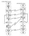
図3は、図1及び図2に示すシステムの動作の理解に役立つフローチャートである。図3において、左側のフローチャートは、ドッキングステーション10(図1)における動作を示し、右側のフローチャートは、ポータブルデバイス20における動作を示す。一意の識別子との通信について、ポータブルデバイス20はマスターとして動作し、ドッキングステーション10はスレーブとして動作する。これらの動作の様式について、以下により詳細に説明する。 FIG. 3 is a flowchart useful for understanding the operation of the system shown in FIGS. 1 and 2. In FIG. 3, the flowchart on the left shows the operation in the docking station 10 (FIG. 1), and the flowchart on the right shows the operation in the portable device 20. For communication with the unique identifier, the portable device 20 operates as a master and the docking station 10 operates as a slave. These modes of operation are described in more detail below.
図1及び図3双方を参照する。プロセスは、ドッキングステーション10ではステップ201において、そしてポータブルデバイス20ではステップ251において、開始する。ステップ202において、ドッキングステーション10中のインターフェースプロセッサ25は、ソース14からパラメータを読みだす。図示の実施形態において、パラメータは、特定のドッキングステーション10に対して一意の識別子又は一意の電子アドレスである。図示の実施形態において、電子アドレスはMAC(Media Access Control)識別子である。しかし、当業者であれば、特定のドッキングステーション10と関連付けられた電子アドレスは、(a)Ethernet(登録商標)に準拠したMACアドレス、(b)IPアドレス、(c)ポート識別子、(d)インターネットに準拠したアドレス、(e)LANアドレス、又は特定のドッキングステーション10を一意に特定することが可能な他の任意の類似の電子アドレスを含み得ることを理解する。 Please refer to both FIG. 1 and FIG. The process begins at step 201 for the docking station 10 and at
ステップ204及びステップ254において、第1の動作モードが行われる。上述したような様式で、ドッキングステーション10及びポータブルデバイス20中の利用可能な通信プロトコルを表すデータを含むLCWの交換が行われる。公知の手順において、共通通信プロトコルが選択される。この場合、NPビットは、LCW[LD]中に設定される。NPビットが設定されると、さらなるデータがポータブルデバイス20によって取得可能であることが示される。応答して、ポータブルデバイス20は、LCW[LP]中のNPビットを設定する。ANSI/IEEE Std 802.3MAC Parameters,Physical Layer,Medium Attachment Units and Repeater for 100Mb/s OperationのD4ドラフトの第28節に定義されたオートネゴシエーション標準に記載のように、NPビットが設定されると、共通通信プロトコルを用いた通信開始が行われる前に、ドッキングステーション10とポータブルデバイス20とのメッセージ交換を行うための同一方法を用いて、さらなるデータが交換される。図3に示す残りの動作は、第2の動作モードを含む。 In
ステップ256において、ポータブルデバイス20からドッキングステーション10へとデータ要求メッセージが送信される。データ要求メッセージは、LCW[LP]として符号化され、その際、Ackビットが設定され、NPビットが設定される。これは、ドッキングステーション10からの先行通信プロトコルデータがポータブルデバイス20によって適切に受信されたことと、ポータブルデバイス20がさらなるデータを受信可能な状態であることとを示す。ステップ206において、ポータブルデバイスからのデータ要求メッセージが、ドッキングステーション10において受信される。 In
MACアドレスは、48ビット又は6バイトを含む。LCWは、11ビットまでのさらなるデータを搬送することができる。図示の実施形態において、MACアドレスは、ドッキングステーション10からポータブルデバイス20へと同時に8ビット又は1バイトで通信される。すなわち、1バイトのMACアドレスを含む6個のメッセージが、ドッキングステーション10からポータブルデバイス20へと送信され、これにより、完全なMACアドレスが搬送される。表2(以下)は、MACアドレスを搬送するLCWメッセージの構造を示す。ビットDO〜D7は、1バイトのMACアドレスMO〜M7を搬送する。ビットD8〜D10は、MACアドレスバイト数N0〜N2を搬送する。バイト1〜6は、MACアドレスの対応バイトを搬送し、バイト7は、多項式X7+X2+1を用いて計算されるMACアドレスのCRCを搬送する。The MAC address includes 48 bits or 6 bytes. The LCW can carry up to 11 bits of additional data. In the illustrated embodiment, the MAC address is communicated simultaneously from the docking station 10 to the portable device 20 in 8 bits or 1 byte. That is, six messages containing a 1-byte MAC address are sent from the docking station 10 to the portable device 20, thereby carrying the complete MAC address. Table 2 (below) shows the structure of the LCW message carrying the MAC address. Bits DO to D7 carry 1-byte MAC addresses MO to M7. Bits D8-D10 carry the number of MAC address bytes N0-N2. Bytes 1-6 carry the corresponding byte of the MAC address, and byte 7 carries the CRC of the MAC address calculated using the polynomial X7 + X2 +1.
ステップ260において、ポータブルデバイス20は、受信されたLCW[LD]中のNPビットの状態を検出する。NPビットが設定されると、これは、他のメッセージが間もなく送信されることを示す。この場合、ステップ256が繰り返される。ステップ256において、MACアドレスの第1のバイトを含むLCW[LD]に応答して送信される肯定応答LCW[LP]は、Ackビットセット、NPビットセット、及び「2」に設定されたバイト数B0〜B3を有し、これにより、MACアドレスのバイト2を含むドッキングステーション10からの次のメッセージを受信するためのデータ要求を形成する。ステップ210において、ドッキングステーション10中のインターフェースプロセッサ25は、MACアドレスのさらなるバイトが通信用に残っているか否かを確認する。MACアドレスのさらなるバイトが通信用に残っている場合、ステップ206が繰り返され、ポータブルデバイス20からのデータ要求メッセージを待機する。このようなデータ要求メッセージが受信されると、ステップ208が行われる。ステップ208において、MACアドレスの要求バイト及びNPビットセットを含むLCW[LD]が構成され、ポータブルデバイス20へと送信される。ステップ206、208、210及び256、258及び260が繰り返され、これにより、MACアドレスの各バイト及びCRCバイトが転送される。 In
ステップ210においてMACアドレスパラメータの最終バイトであるCRCをポータブルデバイス20に通信すべきであると決定されると、ステップ212が実行される。ステップ212において、ドッキングステーション10中のインターフェースプロセッサ25は、MACアドレスのCRCバイトを含みかつNPビットが設定されていないLCW[LD]を構成する。これは、ポータブルデバイス20によって取得可能なさらなるデータが無いことを示す。ステップ258において、このメッセージが受信され、CRCバイトがEthernet(登録商標)コントローラ33によって記憶される。NPビットがポータブルデバイス20によって受信されたLCW[LD]において設定されていなかったため、肯定応答LCW[LP]はAckビットセットを有するが、NPビットは設定されていない。LCW[LP]中のNPビットが設定されていないため、これは、ポータブルデバイス20からのデータ要求ではなく、フルMACアドレスを成功裏に取得したポータブルデバイス20を示す。 If it is determined in step 210 that the CRC, which is the last byte of the MAC address parameter, is to be communicated to the portable device 20,
この場合、ステップ260において、NPビットの状態は、さらなるメッセージが入来していないことを示し、ステップ262において、MACアドレスの6バイトが組み合わされてMACアドレスを形成し、このMACアドレスはMACアドレス記憶部34中に記憶される。加えて、ドッキングステーション10から受信されたCRCと、アドレス記憶部34中に記憶されたMACアドレスから計算されたCRCとを比較する。ステップ216及びステップ266において、ポータブルデバイス20と病院通信ネットワークとの間にネットワーク通信が確立される。ドッキングステーション10において、ステップ216によりマルチプレクサ31(図2)は、光リンク17,19又はRFリンク103のいずれかに病院通信ネットワークへのEthernet(登録商標)リンクを接続する。ポータブルデバイス20において、Ethernet(登録商標)コントローラ33は、光リンク21及び23又はRFリンク107を介して病院通信ネットワークと通信を開始する。上述したように、ポータブルデバイス20のEthernet(登録商標)コントローラ33から病院通信ネットワークへと送信されたメッセージは、送信側ノード識別子としての、記憶部34中のMACアドレスを含む。病院通信ネットワークからポータブルデバイス20中のEthernet(登録商標)コントローラ33によって受信されたメッセージの宛先アドレスと、記憶部34中のMACアドレスとを比較して、これらのアドレスがポータブルデバイス20を宛先としているか否かを決定する。これらのアドレスがポータブルデバイス20を宛先としている場合、Ethernet(登録商標)コントローラ33は、受信されたメッセージを処理する。 In this case, in
通信が確立されると、ポータブルデバイス20をドッキングステーション10からドック解除することが可能になる。例えば分割変圧器15の一次巻線上の電圧変化を検出することによってこれが検出されると、マルチプレクサ31は、RF通信回路103を病院通信ネットワーク及びEthernet(登録商標)コントローラ33へのEthernet(登録商標)リンクへと接続し、ポータブルデバイス20は、RF通信回路107を通じて通信する。ポータブルデバイス20がドッキングステーション内に留まっている場合、ポータブルデバイス20と病院通信ネットワークとの間のリンクは維持される。RFリンクが失われると、ポータブルデバイス20は、上述したドック解除モードとなる。ポータブルデバイス20が通信を失わずに再度ドックされると、負荷感知回路13は、ポータブルデバイスが再度ドックされたことを検出するが、病院通信ネットワークへの活性通信リンクの存在及び/又はポータブルデバイス20とドッキングステーション10との間の活性通信リンクの存在を検出することができる。これらの条件が検出されると、上記にて詳細に説明した通信リンクの再確立が抑制される。 Once communication is established, the portable device 20 can be undocked from the docking station 10. When this is detected, for example by detecting a voltage change on the primary winding of the split transformer 15, the multiplexer 31 causes the
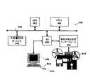
図4は、図1及び図2中に示すポータブルデバイス構成システムの実行が可能なコンピュータシステムのブロック図である。処理システム400は、コンピュータバス405によって相互接続された中央演算処理装置(CPU)402、メモリ404、大容量記憶デバイス406、及び入力/出力(I/O)インターフェース408を含む。I/Oインターフェース408は、ユーザインターフェースに接続される。このユーザインターフェースは、モニタ415、キーボード412及びポインティングデバイス(図示の実施形態ではマウス414)からなる。I/Oインターフェース408はまた、着脱可能な記憶インターフェース410にも接続される。この記憶インターフェース410は、1つ以上の有形電子データ記憶メディア416からのデータ読み出し又はこのメディア416へのデータ記憶を行うことが可能である。有形電子データ記憶メディア416は、磁気デバイス(例えば、オープンリール式コンピュータテープ、カセットテープ)及び磁気ディスクメディア(例えば、フロッピー(登録商標)ディスク)等を含み得る。有形電子データ記憶メディア416は、光デバイス(例えば、デジタルビデオディスク(DVD)又はコンパクトディスク(CD))も含み得る。有形電子データ記憶メディア416は、ポータブル記憶デバイス(例えば、半導体メモリ集積回路(例えば、メモリスティック))等も含み得る。I/Oインターフェース408はまた、他の周辺デバイス(図示せず)(例えば、プリンタ又はリモートシステムとの通信のための通信デバイス、ローカルエリアネットワーク(LAN)又はインターネットのような広域ネットワーク(WAN))とも接続可能である。当業者であれば、着脱可能な記憶インターフェース410はネットワークインターフェース(図示せず)を介してI/Oインターフェース408に接続可能であり、その結果、有形電子データ記憶メディア416を処理システム400から遠隔位置に配置することが可能になることを理解する。 FIG. 4 is a block diagram of a computer system capable of executing the portable device configuration system shown in FIGS.
動作時において、CPU402は、実行可能アプリケーション及び/又は実行可能手順を形成する機械可読式命令を実行するプロセッサとして動作する。これらの機械可読式命令は、メモリ404中に記憶される。メモリ404は、リードオンリメモリ(ROM)及び/又は読み出し/書き込みメモリ(RAM)からなり得る。CPU402は、メモリ404から機械可読式命令を読み出し、機械可読式命令を実行して、上述したシステム動作を行う。 In operation, the
図示の実施形態において、I/Oプロセッサ408は、表示プロセッサを含む。この表示プロセッサは、CPU402からのコマンドに応答して、表示画像を表す信号を生成し、これらの画像表現信号をモニタ415に供給し、モニタ415に画像を表示させる。例えば、患者モニタ用ドッキングステーションにおいて、患者からの生理学的パラメータを表す信号が、表示プロセッサによって生成され得る。これらの画像表現信号は表示デバイス415に供給され、表示デバイス415は、生理学的パラメータを表す画像を表示する。I/Oプロセッサ408はまた、ユーザコマンド並びにキーボード412及び/又はマウス414からのデータも受信し、この情報をCPU402に提供する。CPU402は、受信されたユーザコマンドに及びデータに応答して、上述したように情報取得システムの動作を制御する。 In the illustrated embodiment, the I /
データは、大容量記憶デバイス406から読み出し、大容量記憶デバイス406中に記憶することができる。例えば、大容量記憶デバイス406は、実行可能アプリケーション及び/又は実行可能手順を形成する機械可読式命令を表すデータを記憶することができる。CPU402は、大容量記憶デバイス406から実行可能アプリケーション及び/又は実行可能手順を読み出し、メモリ404中に記憶することができる。CPU402は、メモリ404から機械可読式命令を読み出し、実行可能アプリケーション及び/又は実行可能手順を実行して、上述した動作を行うことができる。 Data can be read from the
データは、ローカル配置又はリモート配置を問わず着脱可能な記憶インターフェース410を介して有形電子データ記憶メディア416から読み出し及び有形電子データ記憶メディア416中に記憶することもできる。任意のデータの有形電子データ記憶メディア416中への記憶及び/又は有形電子データ記憶メディア416からの読み出しが可能である。より詳細には、図示の実施形態において、上述したシステムを形成する実行可能アプリケーション及び/又は実行可能手順中の機械可読式命令は、有形電子データ記憶媒体416中に記憶することができる。CPU402は、I/Oプロセッサ408を支配して、着脱可能な記憶インターフェース410を介して適切な有形電子データ記憶媒体416から実行可能アプリケーション及び/又は実行可能手順を読み出させ、実行可能アプリケーション及び/又は実行可能手順を大容量記憶デバイス406及び/又はメモリ404中に記憶させることができる。CPU402は、メモリ404中の実行可能アプリケーション及び/又は実行可能手順を実行して、上述した動作を行うことができる。 Data can also be read from and stored in the tangible electronic
ポータブル患者モニタ及びドッキングステーションに関連する医療環境において、ポータブルデバイス構成システムについて説明してきた。しかし、このようなシステムは、リピータを通じてノードとして動作することを意図した通信ネットワークに新規デバイスを追加することが可能な任意のシステムにおいても用いることが可能である。 A portable device configuration system has been described in the medical environment associated with portable patient monitors and docking stations. However, such a system can also be used in any system that can add new devices to a communication network intended to operate as a node through a repeater.
10 ドッキングステーション
13 負荷感知回路
15、39 電源カプラ
20 ポータブルデバイス
25 インターフェースプロセッサ
33 Ethernet(登録商標)コントローラ
35 プロセッサ
37 充電器
103、107 RF通信回路
DESCRIPTION OF SYMBOLS 10
Claims (22)
Translated fromJapanese前記第1のデバイスとの通信の際に用いられる通信プロトコルを特定し、さらなるデータが取得可能であることを示す第1のメッセージデータを前記第2のデバイスに通信し、
前記第1のデバイスから受信された、さらなるデータが取得可能である旨を示すデータに応答して開始される1つ以上のデータ要求メッセージを前記第2のデバイスから受信し、
前記第2のデバイスからの1つ以上の対応するデータ要求メッセージに応答して、前記パラメータを1つ以上の分かれたメッセージで前記第2のデバイスに通信し、
前記パラメータが前記第2のデバイスによって取得されたことを示すデータを受信し、
前記パラメータが前記第2のデバイスによって取得されたことを示すデータの受信に応答して、前記第2のデバイスへの通信のためのメッセージデータを更新し、さらなるデータが取得不可能であることを示す、電気回路からなるインターフェースプロセッサを備えるシステム。In a system for communicating parameters from a first device to a second device,
Identifying a communication protocol used in communication with the first device, communicating first message data to the second device indicating that further data can be obtained,
Receiving from the second device one or more data request messages initiated in response to data received from the first device indicating that further data is available;
In response to one or more corresponding data request messages from the second device, communicating the parameters to the second device in one or more separate messages;
Receiving data indicating that the parameter was obtained by the second device;
In response to receiving data indicating that the parameter has been acquired by the second device, update message data for communication to the second device, and no further data can be acquired. A system comprising an interface processor comprising an electrical circuit.
前記パラメータが前記第1のデバイスから前記第2のデバイスへ通信された後に、前記特定された通信プロトコルを用いて前記第1のデバイスと前記第2のデバイスとの間の通信を開始するための電気回路をさらに備える、システム。The system of claim 1, wherein
For initiating communication between the first device and the second device using the identified communication protocol after the parameter is communicated from the first device to the second device The system further comprising an electrical circuit.
第1のデバイスの電子アドレスを示すデータを受信するための入力プロセッサと、
前記第1のデバイスによって、
前記第1のデバイスとの通信の際に用いられる通信プロトコルを特定し、さらなるデータが取得可能であることを示す第1のメッセージデータを前記第2のデバイスに通信し、
前記第2のデバイスからの1つ以上の対応するデータ要求メッセージに応答して、前記電子アドレスを1つ以上の分かれたメッセージで前記第2のデバイスに通信し、
前記データ要求メッセージが前記第1のデバイスから受信された、さらなるデータが取得可能である旨を示すデータに応答して開始される1つ以上の要求メッセージを前記第2のデバイスから受信し、
前記第1のデバイスの電子アドレスが前記第2のデバイスによって取得されたことを示すデータの受信に応答して、前記第2のデバイスへの通信のためのメッセージデータを更新し、さらなるデータが取得不可能であることを示す、ために用いられるインターフェースプロセッサと、
を備えるシステム。In a system for communicating parameters from a first device to a second device,
An input processor for receiving data indicative of the electronic address of the first device;
By the first device,
Identifying a communication protocol used in communication with the first device, communicating first message data to the second device indicating that further data can be obtained,
In response to one or more corresponding data request messages from the second device, communicating the electronic address to the second device in one or more separate messages;
Receiving one or more request messages from the second device, the data request message being received from the first device, which is initiated in response to data indicating that further data is available;
In response to receiving data indicating that the electronic address of the first device has been obtained by the second device, the message data for communication to the second device is updated and further data is obtained. An interface processor used to indicate that it is impossible;
A system comprising:
前記インターフェースプロセッサは、
前記第1のデバイスの電子アドレスが前記第1のデバイスから前記第2のデバイスへ通信された後に、前記特定された通信プロトコルを用いて前記第1のデバイスと前記第2のデバイスとの間の通信を開始する、システム。The system of claim 3, wherein
The interface processor
After the electronic address of the first device is communicated from the first device to the second device, between the first device and the second device using the identified communication protocol A system that initiates communication.
前記第1のデバイスは、ポータブル患者モニタリングデバイスに取り付けることに適しているドッキングステーションであり、
前記第2のデバイスは、ポータブル患者モニタリングデバイスであり、
前記インターフェースプロセッサは、Ethernet(登録商標)に準拠したオートネゴシエーション手順を用いて、前記ドッキングステーションから前記ポータブル患者モニタリングデバイスへ、前記電子アドレスを通信する、システム。The system of claim 3, wherein
The first device is a docking station suitable for attachment to a portable patient monitoring device;
The second device is a portable patient monitoring device;
The interface processor communicates the electronic address from the docking station to the portable patient monitoring device using an Ethernet-compliant auto-negotiation procedure.
前記電子アドレスは、Ethernet(登録商標)に準拠したMACアドレスである、システム。The system of claim 3, wherein
The system, wherein the electronic address is a MAC address compliant with Ethernet (registered trademark).
前記ポータブル処理デバイスは、
信号パラメータを処理するために、ポータブル処理デバイスに電力を供給するために電源に接続するための電源カプラと、
第1の動作モードにおいて、特定のドッキングステーションと関連付けられた識別子を、Ethernet(登録商標)に準拠したオートネゴシエーション手順を用いて前記ポータブル処理デバイスに通信し、
第2の動作モードにおいて、前記ポータブル処理デバイスとネットワークへの接続を確立する、ためのインターフェースプロセッサと、を備えるシステム。In a system used for a docking station that is suitable for attachment to a portable processing device,
The portable processing device includes:
A power coupler for connecting to a power source to supply power to the portable processing device to process the signal parameters;
In a first mode of operation, an identifier associated with a particular docking station is communicated to the portable processing device using an Ethernet-compliant auto-negotiation procedure;
An interface processor for establishing a connection to the portable processing device and a network in a second mode of operation.
ポータブル処理デバイスが前記ドッキングステーションに取り付けられていることを検出し、前記第1の動作モードを開始し、その後前記第2の動作モードを開始するためのコントローラを含むシステム。The system of claim 7, wherein
A system including a controller for detecting that a portable processing device is attached to the docking station, initiating the first mode of operation, and thereafter initiating the second mode of operation.
前記コントローラは、前記ポータブル処理デバイスが前記ドッキングステーションに取り付けられていることを、(a)前記ネットワークとの間の実行中の通信リンクがあること、(b)前記ドッキングステーションと前記ポータブル処理デバイスとの間の実行中の通信リンクがあること、(c)ポータブル患者モニタリングデバイスが前記ドッキングステーションに接続されかつ前記ドッキングステーションから電力を受信していること、のうちの少なくとも1つを検出することによって検出する、システム。The system of claim 8, wherein
The controller includes: (a) there is an active communication link with the network; and (b) the docking station and the portable processing device are attached to the docking station. By detecting at least one of: (c) a portable patient monitoring device connected to and receiving power from the docking station; Detect the system.
コントローラが、前記ポータブル処理デバイスが前記ドッキングステーションに取り付けられ、電力供給されていると判断するまで、前記第1の動作モードを抑制するための前記コントローラを、さらに備えるシステム。The system of claim 7, wherein
The system further comprising the controller for suppressing the first mode of operation until the controller determines that the portable processing device is attached to the docking station and powered.
前記インターフェースプロセッサは、(a)WLAN802.11b標準に準拠した通信、(b)802.3標準に準拠した通信、(c)802.11標準に準拠した通信、(d)Bluetooth(登録商標)802.15標準に準拠した通信、(e)GSM/GPRS標準に準拠した通信、のうちの少なくとも1つを含む無線技術を用いる通信をサポートする、システム。The system of claim 7, wherein
The interface processor includes (a) communication conforming to the WLAN 802.11b standard, (b) communication conforming to the 802.3 standard, (c) communication conforming to the 802.11 standard, and (d) Bluetooth (registered trademark) 802. A system that supports communication using wireless technologies including at least one of communications compliant with the .15 standard and (e) communications compliant with the GSM / GPRS standard.
ドッキングステーションによって使用される通信インターフェースを備え、
前記通信インターフェースは、
前記ドッキングステーションとの通信の際に用いられる通信プロトコルを特定する第1のメッセージデータを前記ポータブル患者モニタリングデバイスに通信し、さらなるデータが取得可能であることを示し、
前記ポータブル患者モニタリングデバイスからの1つ以上の対応するデータ要求メッセージに応答して、前記ドッキングステーションに関連する電子アドレスを1つ以上の分かれたメッセージで前記ポータブル患者モニタリングデバイスに通信し、
前記データ要求メッセージは、前記ドッキングステーションから受信された、さらなるデータが取得可能である旨を示すデータに応答して開始され、
前記通信インターフェースは、
前記ドッキングステーションの前記電子アドレスが前記ポータブル患者モニタリングデバイスによって取得されたことを示すデータを受信したことに応答して、アドレスデータ通信が完了していることを示すメッセージを通信する、システム。In a system for use in a docking station suitable for being attached to a portable patient monitoring device for monitoring and processing signal parameters obtained from a patient,
With a communication interface used by the docking station,
The communication interface is
Communicating first message data identifying a communication protocol used in communication with the docking station to the portable patient monitoring device to indicate that further data can be obtained;
In response to one or more corresponding data request messages from the portable patient monitoring device, communicating an electronic address associated with the docking station to the portable patient monitoring device in one or more separate messages;
The data request message is initiated in response to data received from the docking station indicating that further data is available;
The communication interface is
A system for communicating a message indicating that address data communication is complete in response to receiving data indicating that the electronic address of the docking station has been acquired by the portable patient monitoring device.
前記ドッキングステーションに前記ポータブル患者モニタリングデバイスを挿入したことに応答して、双方向コンフィグレーションデータの交換を行っている間、
前記通信インターフェースは、前記電子アドレスを前記ポータブル患者モニタリングデバイスへ通信する、システム。The system of claim 12, wherein
In response to inserting the portable patient monitoring device into the docking station, while exchanging interactive configuration data,
The communication interface communicates the electronic address to the portable patient monitoring device.
前記ドッキングステーションに前記ポータブル患者モニタリングデバイスを最初に挿入したことに応答して、双方向コンフィグレーションデータの交換を行っている間、
前記通信インターフェースは、前記電子アドレスを前記ポータブル患者モニタリングデバイスへ通信する、システム。The system of claim 12, wherein
In response to the initial insertion of the portable patient monitoring device into the docking station, while exchanging interactive configuration data,
The communication interface communicates the electronic address to the portable patient monitoring device.
第1のデバイスの電子アドレスを示すデータを受取る段階と、
前記第1のデバイスとの通信の際に用いられる通信プロトコルを特定し、さらなるデータが取得可能であることを示す第1のメッセージデータを前記第2のデバイスに通信する段階と、
前記第1のデバイスから受信された、さらなるデータが取得可能である旨を示すデータに応答して開始される、前記第2のデバイスからの1つ以上の対応するデータ要求メッセージに応答して、1つ以上の分かれたメッセージで前記第2のデバイスに前記電子アドレスを通信する段階と、
前記第1のデバイスの電子アドレスが前記第2のデバイスによって取得されたことを示すデータの受信に応答し、前記第2のデバイスへの通信のためのメッセージデータを更新し、さらなるデータが取得不可能であることを示す段階と、
を備える方法。In a method for communicating parameters from a first device to a second device,
Receiving data indicating an electronic address of the first device;
Identifying a communication protocol used in communication with the first device and communicating first message data to the second device indicating that further data can be obtained;
In response to one or more corresponding data request messages from the second device, initiated in response to data received from the first device indicating that further data is available; Communicating the electronic address to the second device in one or more separate messages;
In response to receiving data indicating that the electronic address of the first device has been acquired by the second device, the message data for communication to the second device is updated and no further data is acquired. A stage to show that it is possible,
A method comprising:
ポータブル患者モニタリングデバイスによって使用されるインターフェースプロセッサを備え、
前記インターフェースプロセッサは、
ドッキングステーションとの通信の際に用いられる通信プロトコルを特定する、さらなるデータが取得可能であることを示す第1のメッセージデータを受信し、
1つ以上のデータ要求メッセージを前記ドッキングステーションに通信し、
前記ドッキングステーションから受信された、さらなるデータが取得可能である旨を示すデータに応答して1つ以上のデータ要求メッセージで、前記ドッキングステーションに関連する電子アドレスを前記ドッキングステーションから受信し、
前記電子アドレスを受信することに応答して、アドレスデータ通信が完了していることを示す、前記ドッキングステーションへのメッセージを通信する、システム。In a system for using a portable patient monitoring device suitable for being attached to a docking station for monitoring and processing signal parameters obtained from a patient,
With an interface processor used by the portable patient monitoring device,
The interface processor
Receiving a first message data indicating that further data can be obtained, identifying a communication protocol used in communication with the docking station;
Communicating one or more data request messages to the docking station;
Receiving an electronic address associated with the docking station from the docking station in one or more data request messages in response to data received from the docking station indicating that further data is available;
In response to receiving the electronic address, a system for communicating a message to the docking station indicating that address data communication is complete.
処理された患者パラメータデータを提供するためのセンサを取り付けられた複数の異なった患者から患者パラメータデータを受信し、処理するデータ収集プロセッサと、
処理された患者パラメータデータを表示するためのディスプレイデバイスと、
をさらに備えるシステム。The system of claim 17, wherein
A data acquisition processor for receiving and processing patient parameter data from a plurality of different patients fitted with sensors for providing processed patient parameter data;
A display device for displaying the processed patient parameter data;
Further comprising a system.
前記通信のインターフェースは、前記ポータブル患者モニタリングデバイスが前記ドッキングステーションに取り付けられると前記ドッキングステーションに、(a)心電計(ECG)データ、(b)血液パラメータデータ、(c)換気パラメータデータ、(d)輸液ポンプ関連データ、(e)血圧データ、(f)脈拍データ、(g)温度データ、のうちの少なくとも1つを含む生理学的データからなる、処理された患者パラメータデータを通信する、システム。The system of claim 17, wherein
The communication interface includes: (a) electrocardiograph (ECG) data, (b) blood parameter data, (c) ventilation parameter data, when the portable patient monitoring device is attached to the docking station. A system for communicating processed patient parameter data comprising physiological data including at least one of d) infusion pump related data, (e) blood pressure data, (f) pulse data, (g) temperature data .
前記特定のドッキングステーションと関連付けられた前記電子アドレスは、地理的位置に対応する識別子を関連付けるマップから、前記特定のドッキングステーションの地理的位置の決定を可能にする、システム。The system of claim 17, wherein
The system, wherein the electronic address associated with the particular docking station allows determination of the geographic location of the particular docking station from a map that associates an identifier corresponding to the geographic location.
前記ドッキングステーションに関連付けられる前記電子アドレスは、(a)Ethernet(登録商標)準拠MACアドレス、(b)IPアドレス、(c)ポート識別子、(d)インターネット準拠のアドレス、(e)LANアドレス、のうちの少なくとも1つからなる、システム。The system of claim 17, wherein
The electronic address associated with the docking station is: (a) Ethernet (registered trademark) compliant MAC address, (b) IP address, (c) port identifier, (d) Internet compliant address, (e) LAN address, A system consisting of at least one of them.
前記インターフェースプロセッサは、(a)無線、(b)有線のうち少なくとも1つによって通信する、システム。
The system of claim 17, wherein
The interface processor communicates by at least one of (a) wireless and (b) wired.
Applications Claiming Priority (2)
| Application Number | Priority Date | Filing Date | Title |
|---|---|---|---|
| US62180904P | 2004-10-25 | 2004-10-25 | |
| PCT/US2005/038212WO2006047430A2 (en) | 2004-10-25 | 2005-10-24 | A portable device configuration system |
Publications (1)
| Publication Number | Publication Date |
|---|---|
| JP2008517666Atrue JP2008517666A (en) | 2008-05-29 |
Family
ID=36129115
Family Applications (1)
| Application Number | Title | Priority Date | Filing Date |
|---|---|---|---|
| JP2007538136APendingJP2008517666A (en) | 2004-10-25 | 2005-10-24 | Portable device configuration system |
Country Status (5)
| Country | Link |
|---|---|
| US (1) | US20060098666A1 (en) |
| EP (1) | EP1805607A2 (en) |
| JP (1) | JP2008517666A (en) |
| CN (1) | CN101044455A (en) |
| WO (1) | WO2006047430A2 (en) |
Families Citing this family (19)
| Publication number | Priority date | Publication date | Assignee | Title |
|---|---|---|---|---|
| US7818559B2 (en) | 2007-02-28 | 2010-10-19 | Microsoft Corporation | Boot negotiation among multiple boot-capable devices |
| KR20090015292A (en)* | 2007-08-08 | 2009-02-12 | 삼성전자주식회사 | Method and device for providing information in a mobile terminal |
| US7966040B2 (en)* | 2007-11-08 | 2011-06-21 | Symbol Technologies, Inc. | Magnetically attachable accessories for a mobile unit |
| CN101911017A (en)* | 2007-12-31 | 2010-12-08 | 数据逻辑移动公司 | Systems and methods for configuring, updating, and booting an alternate operating system on a portable data reader |
| US8610310B2 (en) | 2008-02-25 | 2013-12-17 | Tivo Inc. | Wireless ethernet system |
| US8359372B2 (en)* | 2008-06-29 | 2013-01-22 | Microsoft Corporation | Automatic transfer of information through physical docking of devices |
| US20090327515A1 (en)* | 2008-06-30 | 2009-12-31 | Thomas Price | Medical Monitor With Network Connectivity |
| US20100217835A1 (en)* | 2009-02-26 | 2010-08-26 | Broadcom Corporation | Dockable handheld computing device with file transfer and methods for use therewith |
| US10206570B2 (en)* | 2010-02-28 | 2019-02-19 | Covidien Lp | Adaptive wireless body networks |
| US20110213217A1 (en)* | 2010-02-28 | 2011-09-01 | Nellcor Puritan Bennett Llc | Energy optimized sensing techniques |
| US8452877B2 (en)* | 2010-04-28 | 2013-05-28 | Lenovo (Singapore) Pte. Ltd. | Establishing a remote desktop |
| KR101052037B1 (en) | 2010-06-22 | 2011-07-26 | 삼성탈레스 주식회사 | Master / slave operation method between portable TMRs docked in TMR racks and TRM racks |
| US8578082B2 (en) | 2010-07-29 | 2013-11-05 | Covidien LLP | Configurable patient monitoring system |
| US8566498B2 (en) | 2010-08-31 | 2013-10-22 | Palm, Inc. | Docking station with network based personality profile |
| US8671237B2 (en) | 2011-05-31 | 2014-03-11 | Covidien Lp | Patient monitoring platform interface |
| CN103778143B (en)* | 2012-10-22 | 2017-09-01 | 联想(北京)有限公司 | A kind of method, electronic equipment and system for building map |
| US10133307B2 (en)* | 2015-08-28 | 2018-11-20 | Cigna Intellectual Property, Inc. | Dock for extending the utility of an electronic device |
| US11148059B2 (en)* | 2017-09-28 | 2021-10-19 | Ags Llc | Methods for generating and validating gaming machine subscription keys and securing subscription parameter data and jurisdiction files |
| US12048506B2 (en)* | 2020-10-28 | 2024-07-30 | Drägerwerk AG & Co. KGaA | Patient physiological monitor mounting detection |
Family Cites Families (15)
| Publication number | Priority date | Publication date | Assignee | Title |
|---|---|---|---|---|
| US5586117A (en)* | 1992-11-02 | 1996-12-17 | National Semiconductor Corporation | Method and apparatus which allows devices with multiple protocol capabilities to configure to a common protocol configuration |
| DE69318850T2 (en)* | 1992-12-11 | 1998-10-22 | Siemens Medical Systems Inc | DOCKING STATION FOR PATIENT MONITORING SYSTEM |
| JP3425192B2 (en)* | 1993-08-25 | 2003-07-07 | 富士通株式会社 | Address information automatic setting processing method and address information setting device |
| US5432775A (en)* | 1993-12-03 | 1995-07-11 | Advanced Micro Devices, Inc. | Auto negotiation system for a communications network |
| US5640953A (en)* | 1995-03-09 | 1997-06-24 | Siemens Medical Systems, Inc. | Portable patient monitor reconfiguration system |
| US5809249A (en)* | 1995-09-27 | 1998-09-15 | Texas Instruments Incorporated | System having at least one auto-negotiation enabled physical media dependent (PMD) interface device operable to perform auto-negotiation with remote link partner on behalf of all PMD |
| US5884041A (en)* | 1996-03-13 | 1999-03-16 | Ics Technologies, Inc. | Method and apparatus for monitoring auto-negotiation progress |
| US5752917A (en)* | 1996-03-19 | 1998-05-19 | Siemens Medical Systems, Inc. | Network connectivity for a portable patient monitor |
| US6198727B1 (en)* | 1997-03-31 | 2001-03-06 | Hewlett-Packard Company | Method and apparatus for providing 10Base-T/100Base-TX link assurance |
| US5907553A (en)* | 1997-04-08 | 1999-05-25 | Level One Communications, Inc. | Power savings in multiple technology physical layer devices supporting autonegotiation |
| US6349331B1 (en)* | 1998-06-05 | 2002-02-19 | Lsi Logic Corporation | Multiple channel communication system with shared autonegotiation controller |
| EP1162796B1 (en)* | 2000-06-09 | 2012-08-15 | Broadcom Corporation | Cascading of gigabit switches |
| US7818184B2 (en)* | 2002-09-24 | 2010-10-19 | Draeger Medical Systems, Inc. | Patient medical fluid parameter data processing system |
| US20040208180A1 (en)* | 2003-04-15 | 2004-10-21 | Light Allen Miles | System and method for supporting auto-negotiation among standards having different rates |
| WO2005001739A2 (en)* | 2003-06-11 | 2005-01-06 | Draeger Medical Systems, Inc. | A portable patient monitoring system including location identification capability |
- 2005
- 2005-10-24JPJP2007538136Apatent/JP2008517666A/enactivePending
- 2005-10-24WOPCT/US2005/038212patent/WO2006047430A2/enactiveApplication Filing
- 2005-10-24USUS11/257,497patent/US20060098666A1/ennot_activeAbandoned
- 2005-10-24CNCNA2005800362124Apatent/CN101044455A/enactivePending
- 2005-10-24EPEP05818098Apatent/EP1805607A2/ennot_activeWithdrawn
Also Published As
| Publication number | Publication date |
|---|---|
| WO2006047430A2 (en) | 2006-05-04 |
| US20060098666A1 (en) | 2006-05-11 |
| WO2006047430A3 (en) | 2006-11-16 |
| EP1805607A2 (en) | 2007-07-11 |
| CN101044455A (en) | 2007-09-26 |
Similar Documents
| Publication | Publication Date | Title |
|---|---|---|
| JP2008517666A (en) | Portable device configuration system | |
| US7316648B2 (en) | Portable patient monitoring system including location identification capability | |
| US8172752B2 (en) | Automatic wireless PAN/LAN switching | |
| US9250104B2 (en) | Sensor for acquiring physiological signals of a patient | |
| CN108370389B (en) | System and method for transmission of medical devices between networks | |
| CN103797881B (en) | Personal area network (PAN) coordinator and method for distributing multicycle guarantee time slot | |
| CN106462424A (en) | Method for updating terminal system, terminal and system | |
| EP1625671B1 (en) | Method of establishing a wireless communication connection | |
| US9750031B2 (en) | Coordinator switching method for medical body area networks | |
| WO2007012998A1 (en) | System and method for context dependent service discovery for mobile medical devices | |
| JP2007244516A (en) | Conversion adaptor, medical system and transmission method | |
| JP2009033490A (en) | Information communication terminal, radio communication apparatus, and radio communication network | |
| EP4400036A1 (en) | Wearable mobile monitoring device, monitoring system, and data transmission method | |
| CN113452736A (en) | Patient monitoring system and method for establishing data communication connection in patient monitoring system | |
| CN110115570B (en) | Wireless physical sign monitoring system, data monitoring method and terminal when transferring patients | |
| JP2009021941A (en) | Information communication terminal, radio communication device, and radio communication network | |
| CN212518968U (en) | Medical equipment data acquisition unit | |
| CN114698037A (en) | Medical device and communication method for medical device | |
| JP2009038659A (en) | Information communication terminal, radio communication apparatus, and radio communication network | |
| JP7227169B2 (en) | patient monitoring | |
| EP4410341A1 (en) | Medical ventilation device and medical device system | |
| CN114451862A (en) | A communication method and device | |
| WO2024246709A1 (en) | Video laryngoscope and medical device wireless video transfer | |
| CN111865356A (en) | Medical equipment data acquisition unit | |
| CN120783970A (en) | Universal docking station with location context |