JP2008517657A - Nucleus pulposus implants and kits - Google Patents
Nucleus pulposus implants and kitsDownload PDFInfo
- Publication number
- JP2008517657A JP2008517657AJP2007538051AJP2007538051AJP2008517657AJP 2008517657 AJP2008517657 AJP 2008517657AJP 2007538051 AJP2007538051 AJP 2007538051AJP 2007538051 AJP2007538051 AJP 2007538051AJP 2008517657 AJP2008517657 AJP 2008517657A
- Authority
- JP
- Japan
- Prior art keywords
- implant
- elastic body
- kit
- disc
- composite
- Prior art date
- Legal status (The legal status is an assumption and is not a legal conclusion. Google has not performed a legal analysis and makes no representation as to the accuracy of the status listed.)
- Pending
Links
- 239000007943implantSubstances0.000titleclaimsabstractdescription493
- 238000005336crackingMethods0.000claimsabstractdescription8
- 239000000560biocompatible materialSubstances0.000claimsabstract32
- 239000000463materialSubstances0.000claimsdescription59
- 239000002131composite materialSubstances0.000claimsdescription48
- 239000000017hydrogelSubstances0.000claimsdescription28
- 239000003814drugSubstances0.000claimsdescription24
- 229940079593drugDrugs0.000claimsdescription24
- 229920002635polyurethanePolymers0.000claimsdescription21
- 239000004814polyurethaneSubstances0.000claimsdescription21
- 239000000835fiberSubstances0.000claimsdescription17
- 238000003780insertionMethods0.000claimsdescription17
- 230000037431insertionEffects0.000claimsdescription17
- -1polypropylene fumaratePolymers0.000claimsdescription15
- 210000001519tissueAnatomy0.000claimsdescription14
- 239000003102growth factorSubstances0.000claimsdescription13
- 229920001971elastomerPolymers0.000claimsdescription10
- 239000000806elastomerSubstances0.000claimsdescription9
- 238000012986modificationMethods0.000claimsdescription9
- 230000004048modificationEffects0.000claimsdescription9
- 239000004372Polyvinyl alcoholSubstances0.000claimsdescription8
- 229920002451polyvinyl alcoholPolymers0.000claimsdescription8
- 102000007350Bone Morphogenetic ProteinsHuman genes0.000claimsdescription7
- 108010007726Bone Morphogenetic ProteinsProteins0.000claimsdescription7
- 229940112869bone morphogenetic proteinDrugs0.000claimsdescription7
- 238000002513implantationMethods0.000claimsdescription7
- 239000004636vulcanized rubberSubstances0.000claimsdescription7
- 230000037303wrinklesEffects0.000claimsdescription7
- 102000004887Transforming Growth Factor betaHuman genes0.000claimsdescription6
- 108090001012Transforming Growth Factor betaProteins0.000claimsdescription6
- 239000000853adhesiveSubstances0.000claimsdescription6
- 230000001070adhesive effectEffects0.000claimsdescription6
- 229920001296polysiloxanePolymers0.000claimsdescription6
- ZRKFYGHZFMAOKI-QMGMOQQFSA-NtgfbetaChemical compoundC([C@H](NC(=O)[C@H](C(C)C)NC(=O)CNC(=O)[C@H](CCC(O)=O)NC(=O)[C@H](CCCNC(N)=N)NC(=O)[C@H](CC(N)=O)NC(=O)[C@H](CC(C)C)NC(=O)[C@H]([C@@H](C)O)NC(=O)[C@H](CCC(O)=O)NC(=O)[C@H]([C@@H](C)O)NC(=O)[C@H](CC(C)C)NC(=O)CNC(=O)[C@H](C)NC(=O)[C@H](CO)NC(=O)[C@H](CCC(N)=O)NC(=O)[C@@H](NC(=O)[C@H](C)NC(=O)[C@H](C)NC(=O)[C@@H](NC(=O)[C@H](CC(C)C)NC(=O)[C@@H](N)CCSC)C(C)C)[C@@H](C)CC)C(=O)N[C@@H]([C@@H](C)O)C(=O)N[C@@H](C(C)C)C(=O)N[C@@H](CC=1C=CC=CC=1)C(=O)N[C@@H](C)C(=O)N1[C@@H](CCC1)C(=O)N[C@@H]([C@@H](C)O)C(=O)N[C@@H](CC(N)=O)C(=O)N[C@@H](CCC(O)=O)C(=O)N[C@@H](C)C(=O)N[C@@H](CC=1C=CC=CC=1)C(=O)N[C@@H](CCCNC(N)=N)C(=O)N[C@@H](C)C(=O)N[C@@H](CC(C)C)C(=O)N1[C@@H](CCC1)C(=O)N1[C@@H](CCC1)C(=O)N[C@@H](CCCNC(N)=N)C(=O)N[C@@H](CCC(O)=O)C(=O)N[C@@H](CCCNC(N)=N)C(=O)N[C@@H](CO)C(=O)N[C@@H](CCCNC(N)=N)C(=O)N[C@@H](CC(C)C)C(=O)N[C@@H](CC(C)C)C(O)=O)C1=CC=C(O)C=C1ZRKFYGHZFMAOKI-QMGMOQQFSA-N0.000claimsdescription6
- XUIMIQQOPSSXEZ-UHFFFAOYSA-NSiliconChemical compound[Si]XUIMIQQOPSSXEZ-UHFFFAOYSA-N0.000claimsdescription5
- 230000013011matingEffects0.000claimsdescription5
- 229920002239polyacrylonitrilePolymers0.000claimsdescription5
- 229920000098polyolefinPolymers0.000claimsdescription5
- 239000012779reinforcing materialSubstances0.000claimsdescription5
- 239000010703siliconSubstances0.000claimsdescription5
- 229910052710siliconInorganic materials0.000claimsdescription5
- 239000004698PolyethyleneSubstances0.000claimsdescription4
- 239000004721Polyphenylene oxideSubstances0.000claimsdescription4
- 238000007385chemical modificationMethods0.000claimsdescription4
- 229920001577copolymerPolymers0.000claimsdescription4
- 229920001477hydrophilic polymerPolymers0.000claimsdescription4
- 238000011065in-situ storageMethods0.000claimsdescription4
- 229920000570polyetherPolymers0.000claimsdescription4
- 229920000573polyethylenePolymers0.000claimsdescription4
- 239000011148porous materialSubstances0.000claimsdescription4
- 229920002994synthetic fiberPolymers0.000claimsdescription4
- HRPVXLWXLXDGHG-UHFFFAOYSA-NAcrylamideChemical compoundNC(=O)C=CHRPVXLWXLXDGHG-UHFFFAOYSA-N0.000claimsdescription3
- NIXOWILDQLNWCW-UHFFFAOYSA-MAcrylateChemical compound[O-]C(=O)C=CNIXOWILDQLNWCW-UHFFFAOYSA-M0.000claimsdescription3
- 102000009027AlbuminsHuman genes0.000claimsdescription3
- 108010088751AlbuminsProteins0.000claimsdescription3
- 102000008186CollagenHuman genes0.000claimsdescription3
- 108010035532CollagenProteins0.000claimsdescription3
- 102000016942ElastinHuman genes0.000claimsdescription3
- 108010014258ElastinProteins0.000claimsdescription3
- 102000009123FibrinHuman genes0.000claimsdescription3
- 108010073385FibrinProteins0.000claimsdescription3
- BWGVNKXGVNDBDI-UHFFFAOYSA-NFibrin monomerChemical compoundCNC(=O)CNC(=O)CNBWGVNKXGVNDBDI-UHFFFAOYSA-N0.000claimsdescription3
- 108090000723Insulin-Like Growth Factor IProteins0.000claimsdescription3
- 206010061246Intervertebral disc degenerationDiseases0.000claimsdescription3
- 208000001132OsteoporosisDiseases0.000claimsdescription3
- 102000010780Platelet-Derived Growth FactorHuman genes0.000claimsdescription3
- 108010038512Platelet-Derived Growth FactorProteins0.000claimsdescription3
- 229920003171Poly (ethylene oxide)Polymers0.000claimsdescription3
- 239000004952PolyamideSubstances0.000claimsdescription3
- 239000002202Polyethylene glycolSubstances0.000claimsdescription3
- 102000013275SomatomedinsHuman genes0.000claimsdescription3
- 229910001069Ti alloyInorganic materials0.000claimsdescription3
- 229940035676analgesicsDrugs0.000claimsdescription3
- 239000000730antalgic agentSubstances0.000claimsdescription3
- 239000003242anti bacterial agentSubstances0.000claimsdescription3
- 229940124599anti-inflammatory drugDrugs0.000claimsdescription3
- 229940088710antibiotic agentDrugs0.000claimsdescription3
- 210000002805bone matrixAnatomy0.000claimsdescription3
- 229920001436collagenPolymers0.000claimsdescription3
- 208000018180degenerative disc diseaseDiseases0.000claimsdescription3
- 229920002549elastinPolymers0.000claimsdescription3
- 229950003499fibrinDrugs0.000claimsdescription3
- 239000000499gelSubstances0.000claimsdescription3
- 150000004676glycansChemical class0.000claimsdescription3
- 208000015181infectious diseaseDiseases0.000claimsdescription3
- 208000021600intervertebral disc degenerative diseaseDiseases0.000claimsdescription3
- 239000007788liquidSubstances0.000claimsdescription3
- 229920002647polyamidePolymers0.000claimsdescription3
- 229920000728polyesterPolymers0.000claimsdescription3
- 229920001223polyethylene glycolPolymers0.000claimsdescription3
- 229920001299polypropylene fumaratePolymers0.000claimsdescription3
- 229920001282polysaccharidePolymers0.000claimsdescription3
- 239000005017polysaccharideSubstances0.000claimsdescription3
- 229920001343polytetrafluoroethylenePolymers0.000claimsdescription3
- 239000004810polytetrafluoroethyleneSubstances0.000claimsdescription3
- 239000000565sealantSubstances0.000claimsdescription3
- 208000037959spinal tumorDiseases0.000claimsdescription3
- 201000005671spondyloarthropathyDiseases0.000claimsdescription3
- 239000010935stainless steelSubstances0.000claimsdescription3
- 150000003431steroidsChemical class0.000claimsdescription3
- KIUKXJAPPMFGSW-DNGZLQJQSA-N(2S,3S,4S,5R,6R)-6-[(2S,3R,4R,5S,6R)-3-Acetamido-2-[(2S,3S,4R,5R,6R)-6-[(2R,3R,4R,5S,6R)-3-acetamido-2,5-dihydroxy-6-(hydroxymethyl)oxan-4-yl]oxy-2-carboxy-4,5-dihydroxyoxan-3-yl]oxy-5-hydroxy-6-(hydroxymethyl)oxan-4-yl]oxy-3,4,5-trihydroxyoxane-2-carboxylic acidChemical compoundCC(=O)N[C@H]1[C@H](O)O[C@H](CO)[C@@H](O)[C@@H]1O[C@H]1[C@H](O)[C@@H](O)[C@H](O[C@H]2[C@@H]([C@@H](O[C@H]3[C@@H]([C@@H](O)[C@H](O)[C@H](O3)C(O)=O)O)[C@H](O)[C@@H](CO)O2)NC(C)=O)[C@@H](C(O)=O)O1KIUKXJAPPMFGSW-DNGZLQJQSA-N0.000claimsdescription2
- LUEWUZLMQUOBSB-FSKGGBMCSA-N(2s,3s,4s,5s,6r)-2-[(2r,3s,4r,5r,6s)-6-[(2r,3s,4r,5s,6s)-4,5-dihydroxy-2-(hydroxymethyl)-6-[(2r,4r,5s,6r)-4,5,6-trihydroxy-2-(hydroxymethyl)oxan-3-yl]oxyoxan-3-yl]oxy-4,5-dihydroxy-2-(hydroxymethyl)oxan-3-yl]oxy-6-(hydroxymethyl)oxane-3,4,5-triolChemical compoundO[C@H]1[C@@H](O)[C@H](O)[C@@H](CO)O[C@H]1O[C@@H]1[C@@H](CO)O[C@@H](O[C@@H]2[C@H](O[C@@H](OC3[C@H](O[C@@H](O)[C@@H](O)[C@H]3O)CO)[C@@H](O)[C@H]2O)CO)[C@H](O)[C@H]1OLUEWUZLMQUOBSB-FSKGGBMCSA-N0.000claimsdescription2
- 229920002581GlucomannanPolymers0.000claimsdescription2
- OUYCCCASQSFEME-QMMMGPOBSA-NL-tyrosineChemical compoundOC(=O)[C@@H](N)CC1=CC=C(O)C=C1OUYCCCASQSFEME-QMMMGPOBSA-N0.000claimsdescription2
- WHNWPMSKXPGLAX-UHFFFAOYSA-NN-Vinyl-2-pyrrolidoneChemical compoundC=CN1CCCC1=OWHNWPMSKXPGLAX-UHFFFAOYSA-N0.000claimsdescription2
- 229920000954PolyglycolidePolymers0.000claimsdescription2
- 239000004433Thermoplastic polyurethaneSubstances0.000claimsdescription2
- 125000001931aliphatic groupChemical group0.000claimsdescription2
- 239000013536elastomeric materialSubstances0.000claimsdescription2
- 229940046240glucomannanDrugs0.000claimsdescription2
- 229920002674hyaluronanPolymers0.000claimsdescription2
- 229960003160hyaluronic acidDrugs0.000claimsdescription2
- 229920000747poly(lactic acid)Polymers0.000claimsdescription2
- 239000004417polycarbonateSubstances0.000claimsdescription2
- 229920000515polycarbonatePolymers0.000claimsdescription2
- 229920001692polycarbonate urethanePolymers0.000claimsdescription2
- 239000004633polyglycolic acidSubstances0.000claimsdescription2
- 239000004626polylactic acidSubstances0.000claimsdescription2
- 229920000642polymerPolymers0.000claimsdescription2
- 230000003068static effectEffects0.000claimsdescription2
- 229920002803thermoplastic polyurethanePolymers0.000claimsdescription2
- OUYCCCASQSFEME-UHFFFAOYSA-NtyrosineNatural productsOC(=O)C(N)CC1=CC=C(O)C=C1OUYCCCASQSFEME-UHFFFAOYSA-N0.000claimsdescription2
- 229920002554vinyl polymerPolymers0.000claimsdescription2
- 150000001875compoundsChemical class0.000claims7
- XRASRVJYOMVDNP-UHFFFAOYSA-N4-(7-azabicyclo[4.1.0]hepta-1,3,5-triene-7-carbonyl)benzamideChemical compoundC1=CC(C(=O)N)=CC=C1C(=O)N1C2=CC=CC=C21XRASRVJYOMVDNP-UHFFFAOYSA-N0.000claims2
- 229910000684Cobalt-chromeInorganic materials0.000claims2
- JOYRKODLDBILNP-UHFFFAOYSA-NEthyl urethaneChemical compoundCCOC(N)=OJOYRKODLDBILNP-UHFFFAOYSA-N0.000claims2
- RTAQQCXQSZGOHL-UHFFFAOYSA-NTitaniumChemical compound[Ti]RTAQQCXQSZGOHL-UHFFFAOYSA-N0.000claims2
- 229910045601alloyInorganic materials0.000claims2
- 239000000956alloySubstances0.000claims2
- 229920002678cellulosePolymers0.000claims2
- 239000001913celluloseSubstances0.000claims2
- 239000010952cobalt-chromeSubstances0.000claims2
- 239000005445natural materialSubstances0.000claims2
- 239000003566sealing materialSubstances0.000claims2
- 239000012781shape memory materialSubstances0.000claims2
- 239000011343solid materialSubstances0.000claims2
- 229910001220stainless steelInorganic materials0.000claims2
- 239000010936titaniumSubstances0.000claims2
- 229910052719titaniumInorganic materials0.000claims2
- 229920001651CyanoacrylatePolymers0.000claims1
- 102000018233Fibroblast Growth FactorHuman genes0.000claims1
- 108050007372Fibroblast Growth FactorProteins0.000claims1
- 108050002085Fibroblast growth factor 20Proteins0.000claims1
- 102000012558Fibroblast growth factor 20Human genes0.000claims1
- 108010010803GelatinProteins0.000claims1
- MWCLLHOVUTZFKS-UHFFFAOYSA-NMethyl cyanoacrylateChemical compoundCOC(=O)C(=C)C#NMWCLLHOVUTZFKS-UHFFFAOYSA-N0.000claims1
- 229940126864fibroblast growth factorDrugs0.000claims1
- 239000008273gelatinSubstances0.000claims1
- 229920000159gelatinPolymers0.000claims1
- 235000019322gelatineNutrition0.000claims1
- 235000011852gelatine dessertsNutrition0.000claims1
- 230000006378damageEffects0.000abstractdescription11
- 238000004873anchoringMethods0.000abstractdescription7
- 230000033001locomotionEffects0.000abstractdescription6
- 239000011257shell materialSubstances0.000description63
- 238000000034methodMethods0.000description34
- 230000035882stressEffects0.000description11
- 239000011800void materialSubstances0.000description8
- 230000007547defectEffects0.000description7
- 239000012530fluidSubstances0.000description6
- 239000002243precursorSubstances0.000description6
- 238000004891communicationMethods0.000description5
- 239000000243solutionSubstances0.000description5
- 239000002184metalSubstances0.000description4
- 229910052751metalInorganic materials0.000description4
- 230000002093peripheral effectEffects0.000description4
- 230000008439repair processEffects0.000description4
- XLYOFNOQVPJJNP-UHFFFAOYSA-NwaterSubstancesOXLYOFNOQVPJJNP-UHFFFAOYSA-N0.000description4
- 208000002193PainDiseases0.000description3
- 229920000249biocompatible polymerPolymers0.000description3
- 210000000988bone and boneAnatomy0.000description3
- 230000000295complement effectEffects0.000description3
- 238000010168coupling processMethods0.000description3
- 239000013013elastic materialSubstances0.000description3
- 229920005594polymer fiberPolymers0.000description3
- LIKMAJRDDDTEIG-UHFFFAOYSA-N1-hexeneChemical compoundCCCCC=CLIKMAJRDDDTEIG-UHFFFAOYSA-N0.000description2
- IAZDPXIOMUYVGZ-UHFFFAOYSA-NDimethylsulphoxideChemical compoundCS(C)=OIAZDPXIOMUYVGZ-UHFFFAOYSA-N0.000description2
- 208000028389Nerve injuryDiseases0.000description2
- 229920002367PolyisobutenePolymers0.000description2
- FAPWRFPIFSIZLT-UHFFFAOYSA-MSodium chlorideChemical compound[Na+].[Cl-]FAPWRFPIFSIZLT-UHFFFAOYSA-M0.000description2
- 208000027418Wounds and injuryDiseases0.000description2
- 239000011324beadSubstances0.000description2
- 238000005452bendingMethods0.000description2
- 230000008901benefitEffects0.000description2
- 230000015572biosynthetic processEffects0.000description2
- 230000008878couplingEffects0.000description2
- 238000005859coupling reactionMethods0.000description2
- 238000001125extrusionMethods0.000description2
- 239000004744fabricSubstances0.000description2
- 230000004927fusionEffects0.000description2
- 208000014674injuryDiseases0.000description2
- 238000011068loading methodMethods0.000description2
- 230000008764nerve damageEffects0.000description2
- 150000002825nitrilesChemical class0.000description2
- 229920001084poly(chloroprene)Polymers0.000description2
- 229920001195polyisoprenePolymers0.000description2
- 239000002861polymer materialSubstances0.000description2
- 239000000843powderSubstances0.000description2
- 102000004169proteins and genesHuman genes0.000description2
- 108090000623proteins and genesProteins0.000description2
- 231100000241scarToxicity0.000description2
- 239000011780sodium chlorideSubstances0.000description2
- 230000003746surface roughnessEffects0.000description2
- 150000003673urethanesChemical class0.000description2
- UDJZTGMLYITLIQ-UHFFFAOYSA-N1-ethenylpyrrolidineChemical compoundC=CN1CCCC1UDJZTGMLYITLIQ-UHFFFAOYSA-N0.000description1
- IJVRPNIWWODHHA-UHFFFAOYSA-N2-cyanoprop-2-enoic acidChemical classOC(=O)C(=C)C#NIJVRPNIWWODHHA-UHFFFAOYSA-N0.000description1
- VSQLAQKFRFTMNS-UHFFFAOYSA-N5-methylhexa-1,4-dieneChemical compoundCC(C)=CCC=CVSQLAQKFRFTMNS-UHFFFAOYSA-N0.000description1
- 102100028728Bone morphogenetic protein 1Human genes0.000description1
- 108090000654Bone morphogenetic protein 1Proteins0.000description1
- CADZNPYJFOHZDF-UHFFFAOYSA-NCC(C1)(C2C3C2)C1C3[Rh+]Chemical compoundCC(C1)(C2C3C2)C1C3[Rh+]CADZNPYJFOHZDF-UHFFFAOYSA-N0.000description1
- OBLUXXOHYSJDFB-UHFFFAOYSA-NCC(CCC1)CC1C(CC1)CC1C1CC1Chemical compoundCC(CCC1)CC1C(CC1)CC1C1CC1OBLUXXOHYSJDFB-UHFFFAOYSA-N0.000description1
- 229920000049Carbon (fiber)Polymers0.000description1
- 241000282412HomoSpecies0.000description1
- 208000004044HypesthesiaDiseases0.000description1
- 208000003618Intervertebral Disc DisplacementDiseases0.000description1
- 206010050296Intervertebral disc protrusionDiseases0.000description1
- 241000124008MammaliaSpecies0.000description1
- 241001465754MetazoaSpecies0.000description1
- 208000010428Muscle WeaknessDiseases0.000description1
- 206010028372Muscular weaknessDiseases0.000description1
- 206010033799ParalysisDiseases0.000description1
- 239000004696Poly ether ether ketoneSubstances0.000description1
- 229930182556PolyacetalNatural products0.000description1
- 229920000265PolyparaphenylenePolymers0.000description1
- 239000004743PolypropyleneSubstances0.000description1
- 108020004511Recombinant DNAProteins0.000description1
- BLRPTPMANUNPDV-UHFFFAOYSA-NSilaneChemical group[SiH4]BLRPTPMANUNPDV-UHFFFAOYSA-N0.000description1
- 229920002125Sokalan®Polymers0.000description1
- 241001447056UristesSpecies0.000description1
- 230000005856abnormalityEffects0.000description1
- 238000010521absorption reactionMethods0.000description1
- 150000003926acrylamidesChemical class0.000description1
- 150000001252acrylic acid derivativesChemical class0.000description1
- 230000009471actionEffects0.000description1
- 239000012790adhesive layerSubstances0.000description1
- 230000032683agingEffects0.000description1
- 230000004075alterationEffects0.000description1
- 238000013459approachMethods0.000description1
- 230000006399behaviorEffects0.000description1
- 229920001400block copolymerPolymers0.000description1
- 210000001124body fluidAnatomy0.000description1
- 230000010072bone remodelingEffects0.000description1
- 239000004917carbon fiberSubstances0.000description1
- 125000003178carboxy groupChemical group[H]OC(*)=O0.000description1
- 239000000919ceramicSubstances0.000description1
- 238000003486chemical etchingMethods0.000description1
- 125000003636chemical groupChemical group0.000description1
- 239000011248coating agentSubstances0.000description1
- 238000000576coating methodMethods0.000description1
- 230000008602contractionEffects0.000description1
- 238000001816coolingMethods0.000description1
- 238000002425crystallisationMethods0.000description1
- 230000008025crystallizationEffects0.000description1
- 230000007423decreaseEffects0.000description1
- 238000011161developmentMethods0.000description1
- 230000018109developmental processEffects0.000description1
- 238000010586diagramMethods0.000description1
- 201000010099diseaseDiseases0.000description1
- 208000037265diseases, disorders, signs and symptomsDiseases0.000description1
- 238000005553drillingMethods0.000description1
- 238000005516engineering processMethods0.000description1
- BXOUVIIITJXIKB-UHFFFAOYSA-Nethene;styreneChemical groupC=C.C=CC1=CC=CC=C1BXOUVIIITJXIKB-UHFFFAOYSA-N0.000description1
- 238000011049fillingMethods0.000description1
- 230000006870functionEffects0.000description1
- 125000000524functional groupChemical group0.000description1
- 239000011521glassSubstances0.000description1
- 239000003292glueSubstances0.000description1
- 208000034783hypoesthesiaDiseases0.000description1
- 239000004615ingredientSubstances0.000description1
- 238000012977invasive surgical procedureMethods0.000description1
- 230000001788irregularEffects0.000description1
- 230000007774longtermEffects0.000description1
- 230000007246mechanismEffects0.000description1
- 239000007769metal materialSubstances0.000description1
- 150000002739metalsChemical class0.000description1
- VNWKTOKETHGBQD-UHFFFAOYSA-NmethaneChemical compoundCVNWKTOKETHGBQD-UHFFFAOYSA-N0.000description1
- 230000005012migrationEffects0.000description1
- 238000013508migrationMethods0.000description1
- 239000000203mixtureSubstances0.000description1
- 239000002991molded plasticSubstances0.000description1
- 230000000921morphogenic effectEffects0.000description1
- 239000004745nonwoven fabricSubstances0.000description1
- 231100000862numbnessToxicity0.000description1
- 210000000056organAnatomy0.000description1
- 230000000737periodic effectEffects0.000description1
- 238000001020plasma etchingMethods0.000description1
- 229920003023plasticPolymers0.000description1
- 239000004033plasticSubstances0.000description1
- 229920000058polyacrylatePolymers0.000description1
- 239000004584polyacrylic acidSubstances0.000description1
- 229920002530polyetherether ketonePolymers0.000description1
- 229920002338polyhydroxyethylmethacrylatePolymers0.000description1
- 229920006324polyoxymethylenePolymers0.000description1
- 229920001155polypropylenePolymers0.000description1
- KUKFKAPJCRZILJ-UHFFFAOYSA-Nprop-2-enenitrile;prop-2-enoic acidChemical compoundC=CC#N.OC(=O)C=CKUKFKAPJCRZILJ-UHFFFAOYSA-N0.000description1
- 239000005060rubberSubstances0.000description1
- 238000007789sealingMethods0.000description1
- 230000035939shockEffects0.000description1
- 239000007787solidSubstances0.000description1
- 239000002904solventSubstances0.000description1
- 210000001032spinal nerveAnatomy0.000description1
- 238000005507sprayingMethods0.000description1
- 229910001256stainless steel alloyInorganic materials0.000description1
- 230000001954sterilising effectEffects0.000description1
- 238000004659sterilization and disinfectionMethods0.000description1
- 239000000126substanceSubstances0.000description1
- 238000001356surgical procedureMethods0.000description1
- 208000024891symptomDiseases0.000description1
- MHSKRLJMQQNJNC-UHFFFAOYSA-NterephthalamideChemical compoundNC(=O)C1=CC=C(C(N)=O)C=C1MHSKRLJMQQNJNC-UHFFFAOYSA-N0.000description1
- 125000000383tetramethylene groupChemical group[H]C([H])([*:1])C([H])([H])C([H])([H])C([H])([H])[*:2]0.000description1
- 238000012546transferMethods0.000description1
- 230000008733traumaEffects0.000description1
- 238000004073vulcanizationMethods0.000description1
- 239000002759woven fabricSubstances0.000description1
Images


Classifications
- A—HUMAN NECESSITIES
- A61—MEDICAL OR VETERINARY SCIENCE; HYGIENE
- A61F—FILTERS IMPLANTABLE INTO BLOOD VESSELS; PROSTHESES; DEVICES PROVIDING PATENCY TO, OR PREVENTING COLLAPSING OF, TUBULAR STRUCTURES OF THE BODY, e.g. STENTS; ORTHOPAEDIC, NURSING OR CONTRACEPTIVE DEVICES; FOMENTATION; TREATMENT OR PROTECTION OF EYES OR EARS; BANDAGES, DRESSINGS OR ABSORBENT PADS; FIRST-AID KITS
- A61F2/00—Filters implantable into blood vessels; Prostheses, i.e. artificial substitutes or replacements for parts of the body; Appliances for connecting them with the body; Devices providing patency to, or preventing collapsing of, tubular structures of the body, e.g. stents
- A61F2/02—Prostheses implantable into the body
- A61F2/30—Joints
- A61F2/44—Joints for the spine, e.g. vertebrae, spinal discs
- A61F2/442—Intervertebral or spinal discs, e.g. resilient
- A—HUMAN NECESSITIES
- A61—MEDICAL OR VETERINARY SCIENCE; HYGIENE
- A61F—FILTERS IMPLANTABLE INTO BLOOD VESSELS; PROSTHESES; DEVICES PROVIDING PATENCY TO, OR PREVENTING COLLAPSING OF, TUBULAR STRUCTURES OF THE BODY, e.g. STENTS; ORTHOPAEDIC, NURSING OR CONTRACEPTIVE DEVICES; FOMENTATION; TREATMENT OR PROTECTION OF EYES OR EARS; BANDAGES, DRESSINGS OR ABSORBENT PADS; FIRST-AID KITS
- A61F2/00—Filters implantable into blood vessels; Prostheses, i.e. artificial substitutes or replacements for parts of the body; Appliances for connecting them with the body; Devices providing patency to, or preventing collapsing of, tubular structures of the body, e.g. stents
- A61F2/02—Prostheses implantable into the body
- A61F2/30—Joints
- A61F2/46—Special tools for implanting artificial joints
- A61F2/4603—Special tools for implanting artificial joints for insertion or extraction of endoprosthetic joints or of accessories thereof
- A61F2/4611—Special tools for implanting artificial joints for insertion or extraction of endoprosthetic joints or of accessories thereof of spinal prostheses
- A—HUMAN NECESSITIES
- A61—MEDICAL OR VETERINARY SCIENCE; HYGIENE
- A61P—SPECIFIC THERAPEUTIC ACTIVITY OF CHEMICAL COMPOUNDS OR MEDICINAL PREPARATIONS
- A61P19/00—Drugs for skeletal disorders
- A61P19/08—Drugs for skeletal disorders for bone diseases, e.g. rachitism, Paget's disease
- A—HUMAN NECESSITIES
- A61—MEDICAL OR VETERINARY SCIENCE; HYGIENE
- A61F—FILTERS IMPLANTABLE INTO BLOOD VESSELS; PROSTHESES; DEVICES PROVIDING PATENCY TO, OR PREVENTING COLLAPSING OF, TUBULAR STRUCTURES OF THE BODY, e.g. STENTS; ORTHOPAEDIC, NURSING OR CONTRACEPTIVE DEVICES; FOMENTATION; TREATMENT OR PROTECTION OF EYES OR EARS; BANDAGES, DRESSINGS OR ABSORBENT PADS; FIRST-AID KITS
- A61F2/00—Filters implantable into blood vessels; Prostheses, i.e. artificial substitutes or replacements for parts of the body; Appliances for connecting them with the body; Devices providing patency to, or preventing collapsing of, tubular structures of the body, e.g. stents
- A61F2/02—Prostheses implantable into the body
- A61F2/30—Joints
- A61F2002/30001—Additional features of subject-matter classified in A61F2/28, A61F2/30 and subgroups thereof
- A61F2002/30003—Material related properties of the prosthesis or of a coating on the prosthesis
- A61F2002/3006—Properties of materials and coating materials
- A61F2002/30062—(bio)absorbable, biodegradable, bioerodable, (bio)resorbable, resorptive
- A—HUMAN NECESSITIES
- A61—MEDICAL OR VETERINARY SCIENCE; HYGIENE
- A61F—FILTERS IMPLANTABLE INTO BLOOD VESSELS; PROSTHESES; DEVICES PROVIDING PATENCY TO, OR PREVENTING COLLAPSING OF, TUBULAR STRUCTURES OF THE BODY, e.g. STENTS; ORTHOPAEDIC, NURSING OR CONTRACEPTIVE DEVICES; FOMENTATION; TREATMENT OR PROTECTION OF EYES OR EARS; BANDAGES, DRESSINGS OR ABSORBENT PADS; FIRST-AID KITS
- A61F2/00—Filters implantable into blood vessels; Prostheses, i.e. artificial substitutes or replacements for parts of the body; Appliances for connecting them with the body; Devices providing patency to, or preventing collapsing of, tubular structures of the body, e.g. stents
- A61F2/02—Prostheses implantable into the body
- A61F2/30—Joints
- A61F2002/30001—Additional features of subject-matter classified in A61F2/28, A61F2/30 and subgroups thereof
- A61F2002/30003—Material related properties of the prosthesis or of a coating on the prosthesis
- A61F2002/3006—Properties of materials and coating materials
- A61F2002/30092—Properties of materials and coating materials using shape memory or superelastic materials, e.g. nitinol
- A—HUMAN NECESSITIES
- A61—MEDICAL OR VETERINARY SCIENCE; HYGIENE
- A61F—FILTERS IMPLANTABLE INTO BLOOD VESSELS; PROSTHESES; DEVICES PROVIDING PATENCY TO, OR PREVENTING COLLAPSING OF, TUBULAR STRUCTURES OF THE BODY, e.g. STENTS; ORTHOPAEDIC, NURSING OR CONTRACEPTIVE DEVICES; FOMENTATION; TREATMENT OR PROTECTION OF EYES OR EARS; BANDAGES, DRESSINGS OR ABSORBENT PADS; FIRST-AID KITS
- A61F2/00—Filters implantable into blood vessels; Prostheses, i.e. artificial substitutes or replacements for parts of the body; Appliances for connecting them with the body; Devices providing patency to, or preventing collapsing of, tubular structures of the body, e.g. stents
- A61F2/02—Prostheses implantable into the body
- A61F2/30—Joints
- A61F2002/30001—Additional features of subject-matter classified in A61F2/28, A61F2/30 and subgroups thereof
- A61F2002/30108—Shapes
- A61F2002/30199—Three-dimensional shapes
- A61F2002/302—Three-dimensional shapes toroidal, e.g. rings
- A—HUMAN NECESSITIES
- A61—MEDICAL OR VETERINARY SCIENCE; HYGIENE
- A61F—FILTERS IMPLANTABLE INTO BLOOD VESSELS; PROSTHESES; DEVICES PROVIDING PATENCY TO, OR PREVENTING COLLAPSING OF, TUBULAR STRUCTURES OF THE BODY, e.g. STENTS; ORTHOPAEDIC, NURSING OR CONTRACEPTIVE DEVICES; FOMENTATION; TREATMENT OR PROTECTION OF EYES OR EARS; BANDAGES, DRESSINGS OR ABSORBENT PADS; FIRST-AID KITS
- A61F2/00—Filters implantable into blood vessels; Prostheses, i.e. artificial substitutes or replacements for parts of the body; Appliances for connecting them with the body; Devices providing patency to, or preventing collapsing of, tubular structures of the body, e.g. stents
- A61F2/02—Prostheses implantable into the body
- A61F2/30—Joints
- A61F2002/30001—Additional features of subject-matter classified in A61F2/28, A61F2/30 and subgroups thereof
- A61F2002/30108—Shapes
- A61F2002/30199—Three-dimensional shapes
- A61F2002/30291—Three-dimensional shapes spirally-coiled, i.e. having a 2D spiral cross-section
- A—HUMAN NECESSITIES
- A61—MEDICAL OR VETERINARY SCIENCE; HYGIENE
- A61F—FILTERS IMPLANTABLE INTO BLOOD VESSELS; PROSTHESES; DEVICES PROVIDING PATENCY TO, OR PREVENTING COLLAPSING OF, TUBULAR STRUCTURES OF THE BODY, e.g. STENTS; ORTHOPAEDIC, NURSING OR CONTRACEPTIVE DEVICES; FOMENTATION; TREATMENT OR PROTECTION OF EYES OR EARS; BANDAGES, DRESSINGS OR ABSORBENT PADS; FIRST-AID KITS
- A61F2/00—Filters implantable into blood vessels; Prostheses, i.e. artificial substitutes or replacements for parts of the body; Appliances for connecting them with the body; Devices providing patency to, or preventing collapsing of, tubular structures of the body, e.g. stents
- A61F2/02—Prostheses implantable into the body
- A61F2/30—Joints
- A61F2002/30001—Additional features of subject-matter classified in A61F2/28, A61F2/30 and subgroups thereof
- A61F2002/30316—The prosthesis having different structural features at different locations within the same prosthesis; Connections between prosthetic parts; Special structural features of bone or joint prostheses not otherwise provided for
- A61F2002/30329—Connections or couplings between prosthetic parts, e.g. between modular parts; Connecting elements
- A61F2002/30331—Connections or couplings between prosthetic parts, e.g. between modular parts; Connecting elements made by longitudinally pushing a protrusion into a complementarily-shaped recess, e.g. held by friction fit
- A—HUMAN NECESSITIES
- A61—MEDICAL OR VETERINARY SCIENCE; HYGIENE
- A61F—FILTERS IMPLANTABLE INTO BLOOD VESSELS; PROSTHESES; DEVICES PROVIDING PATENCY TO, OR PREVENTING COLLAPSING OF, TUBULAR STRUCTURES OF THE BODY, e.g. STENTS; ORTHOPAEDIC, NURSING OR CONTRACEPTIVE DEVICES; FOMENTATION; TREATMENT OR PROTECTION OF EYES OR EARS; BANDAGES, DRESSINGS OR ABSORBENT PADS; FIRST-AID KITS
- A61F2/00—Filters implantable into blood vessels; Prostheses, i.e. artificial substitutes or replacements for parts of the body; Appliances for connecting them with the body; Devices providing patency to, or preventing collapsing of, tubular structures of the body, e.g. stents
- A61F2/02—Prostheses implantable into the body
- A61F2/30—Joints
- A61F2002/30001—Additional features of subject-matter classified in A61F2/28, A61F2/30 and subgroups thereof
- A61F2002/30316—The prosthesis having different structural features at different locations within the same prosthesis; Connections between prosthetic parts; Special structural features of bone or joint prostheses not otherwise provided for
- A61F2002/30329—Connections or couplings between prosthetic parts, e.g. between modular parts; Connecting elements
- A61F2002/30476—Connections or couplings between prosthetic parts, e.g. between modular parts; Connecting elements locked by an additional locking mechanism
- A61F2002/305—Snap connection
- A—HUMAN NECESSITIES
- A61—MEDICAL OR VETERINARY SCIENCE; HYGIENE
- A61F—FILTERS IMPLANTABLE INTO BLOOD VESSELS; PROSTHESES; DEVICES PROVIDING PATENCY TO, OR PREVENTING COLLAPSING OF, TUBULAR STRUCTURES OF THE BODY, e.g. STENTS; ORTHOPAEDIC, NURSING OR CONTRACEPTIVE DEVICES; FOMENTATION; TREATMENT OR PROTECTION OF EYES OR EARS; BANDAGES, DRESSINGS OR ABSORBENT PADS; FIRST-AID KITS
- A61F2/00—Filters implantable into blood vessels; Prostheses, i.e. artificial substitutes or replacements for parts of the body; Appliances for connecting them with the body; Devices providing patency to, or preventing collapsing of, tubular structures of the body, e.g. stents
- A61F2/02—Prostheses implantable into the body
- A61F2/30—Joints
- A61F2002/30001—Additional features of subject-matter classified in A61F2/28, A61F2/30 and subgroups thereof
- A61F2002/30316—The prosthesis having different structural features at different locations within the same prosthesis; Connections between prosthetic parts; Special structural features of bone or joint prostheses not otherwise provided for
- A61F2002/30535—Special structural features of bone or joint prostheses not otherwise provided for
- A61F2002/30579—Special structural features of bone or joint prostheses not otherwise provided for with mechanically expandable devices, e.g. fixation devices
- A—HUMAN NECESSITIES
- A61—MEDICAL OR VETERINARY SCIENCE; HYGIENE
- A61F—FILTERS IMPLANTABLE INTO BLOOD VESSELS; PROSTHESES; DEVICES PROVIDING PATENCY TO, OR PREVENTING COLLAPSING OF, TUBULAR STRUCTURES OF THE BODY, e.g. STENTS; ORTHOPAEDIC, NURSING OR CONTRACEPTIVE DEVICES; FOMENTATION; TREATMENT OR PROTECTION OF EYES OR EARS; BANDAGES, DRESSINGS OR ABSORBENT PADS; FIRST-AID KITS
- A61F2/00—Filters implantable into blood vessels; Prostheses, i.e. artificial substitutes or replacements for parts of the body; Appliances for connecting them with the body; Devices providing patency to, or preventing collapsing of, tubular structures of the body, e.g. stents
- A61F2/02—Prostheses implantable into the body
- A61F2/30—Joints
- A61F2002/30001—Additional features of subject-matter classified in A61F2/28, A61F2/30 and subgroups thereof
- A61F2002/30316—The prosthesis having different structural features at different locations within the same prosthesis; Connections between prosthetic parts; Special structural features of bone or joint prostheses not otherwise provided for
- A61F2002/30535—Special structural features of bone or joint prostheses not otherwise provided for
- A61F2002/30594—Special structural features of bone or joint prostheses not otherwise provided for slotted, e.g. radial or meridian slot ending in a polar aperture, non-polar slots, horizontal or arcuate slots
- A—HUMAN NECESSITIES
- A61—MEDICAL OR VETERINARY SCIENCE; HYGIENE
- A61F—FILTERS IMPLANTABLE INTO BLOOD VESSELS; PROSTHESES; DEVICES PROVIDING PATENCY TO, OR PREVENTING COLLAPSING OF, TUBULAR STRUCTURES OF THE BODY, e.g. STENTS; ORTHOPAEDIC, NURSING OR CONTRACEPTIVE DEVICES; FOMENTATION; TREATMENT OR PROTECTION OF EYES OR EARS; BANDAGES, DRESSINGS OR ABSORBENT PADS; FIRST-AID KITS
- A61F2/00—Filters implantable into blood vessels; Prostheses, i.e. artificial substitutes or replacements for parts of the body; Appliances for connecting them with the body; Devices providing patency to, or preventing collapsing of, tubular structures of the body, e.g. stents
- A61F2/02—Prostheses implantable into the body
- A61F2/30—Joints
- A61F2/30767—Special external or bone-contacting surface, e.g. coating for improving bone ingrowth
- A61F2/30771—Special external or bone-contacting surface, e.g. coating for improving bone ingrowth applied in original prostheses, e.g. holes or grooves
- A61F2002/3082—Grooves
- A—HUMAN NECESSITIES
- A61—MEDICAL OR VETERINARY SCIENCE; HYGIENE
- A61F—FILTERS IMPLANTABLE INTO BLOOD VESSELS; PROSTHESES; DEVICES PROVIDING PATENCY TO, OR PREVENTING COLLAPSING OF, TUBULAR STRUCTURES OF THE BODY, e.g. STENTS; ORTHOPAEDIC, NURSING OR CONTRACEPTIVE DEVICES; FOMENTATION; TREATMENT OR PROTECTION OF EYES OR EARS; BANDAGES, DRESSINGS OR ABSORBENT PADS; FIRST-AID KITS
- A61F2/00—Filters implantable into blood vessels; Prostheses, i.e. artificial substitutes or replacements for parts of the body; Appliances for connecting them with the body; Devices providing patency to, or preventing collapsing of, tubular structures of the body, e.g. stents
- A61F2/02—Prostheses implantable into the body
- A61F2/30—Joints
- A61F2/30767—Special external or bone-contacting surface, e.g. coating for improving bone ingrowth
- A61F2/30771—Special external or bone-contacting surface, e.g. coating for improving bone ingrowth applied in original prostheses, e.g. holes or grooves
- A61F2002/30841—Sharp anchoring protrusions for impaction into the bone, e.g. sharp pins, spikes
- A—HUMAN NECESSITIES
- A61—MEDICAL OR VETERINARY SCIENCE; HYGIENE
- A61F—FILTERS IMPLANTABLE INTO BLOOD VESSELS; PROSTHESES; DEVICES PROVIDING PATENCY TO, OR PREVENTING COLLAPSING OF, TUBULAR STRUCTURES OF THE BODY, e.g. STENTS; ORTHOPAEDIC, NURSING OR CONTRACEPTIVE DEVICES; FOMENTATION; TREATMENT OR PROTECTION OF EYES OR EARS; BANDAGES, DRESSINGS OR ABSORBENT PADS; FIRST-AID KITS
- A61F2/00—Filters implantable into blood vessels; Prostheses, i.e. artificial substitutes or replacements for parts of the body; Appliances for connecting them with the body; Devices providing patency to, or preventing collapsing of, tubular structures of the body, e.g. stents
- A61F2/02—Prostheses implantable into the body
- A61F2/30—Joints
- A61F2/30767—Special external or bone-contacting surface, e.g. coating for improving bone ingrowth
- A61F2/30771—Special external or bone-contacting surface, e.g. coating for improving bone ingrowth applied in original prostheses, e.g. holes or grooves
- A61F2002/30878—Special external or bone-contacting surface, e.g. coating for improving bone ingrowth applied in original prostheses, e.g. holes or grooves with non-sharp protrusions, for instance contacting the bone for anchoring, e.g. keels, pegs, pins, posts, shanks, stems, struts
- A61F2002/30891—Plurality of protrusions
- A61F2002/30892—Plurality of protrusions parallel
- A—HUMAN NECESSITIES
- A61—MEDICAL OR VETERINARY SCIENCE; HYGIENE
- A61F—FILTERS IMPLANTABLE INTO BLOOD VESSELS; PROSTHESES; DEVICES PROVIDING PATENCY TO, OR PREVENTING COLLAPSING OF, TUBULAR STRUCTURES OF THE BODY, e.g. STENTS; ORTHOPAEDIC, NURSING OR CONTRACEPTIVE DEVICES; FOMENTATION; TREATMENT OR PROTECTION OF EYES OR EARS; BANDAGES, DRESSINGS OR ABSORBENT PADS; FIRST-AID KITS
- A61F2/00—Filters implantable into blood vessels; Prostheses, i.e. artificial substitutes or replacements for parts of the body; Appliances for connecting them with the body; Devices providing patency to, or preventing collapsing of, tubular structures of the body, e.g. stents
- A61F2/02—Prostheses implantable into the body
- A61F2/30—Joints
- A61F2/44—Joints for the spine, e.g. vertebrae, spinal discs
- A61F2/442—Intervertebral or spinal discs, e.g. resilient
- A61F2002/444—Intervertebral or spinal discs, e.g. resilient for replacing the nucleus pulposus
- A—HUMAN NECESSITIES
- A61—MEDICAL OR VETERINARY SCIENCE; HYGIENE
- A61F—FILTERS IMPLANTABLE INTO BLOOD VESSELS; PROSTHESES; DEVICES PROVIDING PATENCY TO, OR PREVENTING COLLAPSING OF, TUBULAR STRUCTURES OF THE BODY, e.g. STENTS; ORTHOPAEDIC, NURSING OR CONTRACEPTIVE DEVICES; FOMENTATION; TREATMENT OR PROTECTION OF EYES OR EARS; BANDAGES, DRESSINGS OR ABSORBENT PADS; FIRST-AID KITS
- A61F2/00—Filters implantable into blood vessels; Prostheses, i.e. artificial substitutes or replacements for parts of the body; Appliances for connecting them with the body; Devices providing patency to, or preventing collapsing of, tubular structures of the body, e.g. stents
- A61F2/02—Prostheses implantable into the body
- A61F2/30—Joints
- A61F2/44—Joints for the spine, e.g. vertebrae, spinal discs
- A61F2002/4495—Joints for the spine, e.g. vertebrae, spinal discs having a fabric structure, e.g. made from wires or fibres
- A—HUMAN NECESSITIES
- A61—MEDICAL OR VETERINARY SCIENCE; HYGIENE
- A61F—FILTERS IMPLANTABLE INTO BLOOD VESSELS; PROSTHESES; DEVICES PROVIDING PATENCY TO, OR PREVENTING COLLAPSING OF, TUBULAR STRUCTURES OF THE BODY, e.g. STENTS; ORTHOPAEDIC, NURSING OR CONTRACEPTIVE DEVICES; FOMENTATION; TREATMENT OR PROTECTION OF EYES OR EARS; BANDAGES, DRESSINGS OR ABSORBENT PADS; FIRST-AID KITS
- A61F2/00—Filters implantable into blood vessels; Prostheses, i.e. artificial substitutes or replacements for parts of the body; Appliances for connecting them with the body; Devices providing patency to, or preventing collapsing of, tubular structures of the body, e.g. stents
- A61F2/02—Prostheses implantable into the body
- A61F2/30—Joints
- A61F2/46—Special tools for implanting artificial joints
- A61F2/4603—Special tools for implanting artificial joints for insertion or extraction of endoprosthetic joints or of accessories thereof
- A61F2002/4625—Special tools for implanting artificial joints for insertion or extraction of endoprosthetic joints or of accessories thereof with relative movement between parts of the instrument during use
- A61F2002/4627—Special tools for implanting artificial joints for insertion or extraction of endoprosthetic joints or of accessories thereof with relative movement between parts of the instrument during use with linear motion along or rotating motion about the instrument axis or the implantation direction, e.g. telescopic, along a guiding rod, screwing inside the instrument
- A—HUMAN NECESSITIES
- A61—MEDICAL OR VETERINARY SCIENCE; HYGIENE
- A61F—FILTERS IMPLANTABLE INTO BLOOD VESSELS; PROSTHESES; DEVICES PROVIDING PATENCY TO, OR PREVENTING COLLAPSING OF, TUBULAR STRUCTURES OF THE BODY, e.g. STENTS; ORTHOPAEDIC, NURSING OR CONTRACEPTIVE DEVICES; FOMENTATION; TREATMENT OR PROTECTION OF EYES OR EARS; BANDAGES, DRESSINGS OR ABSORBENT PADS; FIRST-AID KITS
- A61F2/00—Filters implantable into blood vessels; Prostheses, i.e. artificial substitutes or replacements for parts of the body; Appliances for connecting them with the body; Devices providing patency to, or preventing collapsing of, tubular structures of the body, e.g. stents
- A61F2/02—Prostheses implantable into the body
- A61F2/30—Joints
- A61F2/46—Special tools for implanting artificial joints
- A61F2/4603—Special tools for implanting artificial joints for insertion or extraction of endoprosthetic joints or of accessories thereof
- A61F2002/4625—Special tools for implanting artificial joints for insertion or extraction of endoprosthetic joints or of accessories thereof with relative movement between parts of the instrument during use
- A61F2002/4628—Special tools for implanting artificial joints for insertion or extraction of endoprosthetic joints or of accessories thereof with relative movement between parts of the instrument during use with linear motion along or rotating motion about an axis transverse to the instrument axis or to the implantation direction, e.g. clamping
- A—HUMAN NECESSITIES
- A61—MEDICAL OR VETERINARY SCIENCE; HYGIENE
- A61F—FILTERS IMPLANTABLE INTO BLOOD VESSELS; PROSTHESES; DEVICES PROVIDING PATENCY TO, OR PREVENTING COLLAPSING OF, TUBULAR STRUCTURES OF THE BODY, e.g. STENTS; ORTHOPAEDIC, NURSING OR CONTRACEPTIVE DEVICES; FOMENTATION; TREATMENT OR PROTECTION OF EYES OR EARS; BANDAGES, DRESSINGS OR ABSORBENT PADS; FIRST-AID KITS
- A61F2210/00—Particular material properties of prostheses classified in groups A61F2/00 - A61F2/26 or A61F2/82 or A61F9/00 or A61F11/00 or subgroups thereof
- A61F2210/0004—Particular material properties of prostheses classified in groups A61F2/00 - A61F2/26 or A61F2/82 or A61F9/00 or A61F11/00 or subgroups thereof bioabsorbable
- A—HUMAN NECESSITIES
- A61—MEDICAL OR VETERINARY SCIENCE; HYGIENE
- A61F—FILTERS IMPLANTABLE INTO BLOOD VESSELS; PROSTHESES; DEVICES PROVIDING PATENCY TO, OR PREVENTING COLLAPSING OF, TUBULAR STRUCTURES OF THE BODY, e.g. STENTS; ORTHOPAEDIC, NURSING OR CONTRACEPTIVE DEVICES; FOMENTATION; TREATMENT OR PROTECTION OF EYES OR EARS; BANDAGES, DRESSINGS OR ABSORBENT PADS; FIRST-AID KITS
- A61F2210/00—Particular material properties of prostheses classified in groups A61F2/00 - A61F2/26 or A61F2/82 or A61F9/00 or A61F11/00 or subgroups thereof
- A61F2210/0014—Particular material properties of prostheses classified in groups A61F2/00 - A61F2/26 or A61F2/82 or A61F9/00 or A61F11/00 or subgroups thereof using shape memory or superelastic materials, e.g. nitinol
- A—HUMAN NECESSITIES
- A61—MEDICAL OR VETERINARY SCIENCE; HYGIENE
- A61F—FILTERS IMPLANTABLE INTO BLOOD VESSELS; PROSTHESES; DEVICES PROVIDING PATENCY TO, OR PREVENTING COLLAPSING OF, TUBULAR STRUCTURES OF THE BODY, e.g. STENTS; ORTHOPAEDIC, NURSING OR CONTRACEPTIVE DEVICES; FOMENTATION; TREATMENT OR PROTECTION OF EYES OR EARS; BANDAGES, DRESSINGS OR ABSORBENT PADS; FIRST-AID KITS
- A61F2220/00—Fixations or connections for prostheses classified in groups A61F2/00 - A61F2/26 or A61F2/82 or A61F9/00 or A61F11/00 or subgroups thereof
- A61F2220/0025—Connections or couplings between prosthetic parts, e.g. between modular parts; Connecting elements
- A61F2220/0033—Connections or couplings between prosthetic parts, e.g. between modular parts; Connecting elements made by longitudinally pushing a protrusion into a complementary-shaped recess, e.g. held by friction fit
- A—HUMAN NECESSITIES
- A61—MEDICAL OR VETERINARY SCIENCE; HYGIENE
- A61F—FILTERS IMPLANTABLE INTO BLOOD VESSELS; PROSTHESES; DEVICES PROVIDING PATENCY TO, OR PREVENTING COLLAPSING OF, TUBULAR STRUCTURES OF THE BODY, e.g. STENTS; ORTHOPAEDIC, NURSING OR CONTRACEPTIVE DEVICES; FOMENTATION; TREATMENT OR PROTECTION OF EYES OR EARS; BANDAGES, DRESSINGS OR ABSORBENT PADS; FIRST-AID KITS
- A61F2230/00—Geometry of prostheses classified in groups A61F2/00 - A61F2/26 or A61F2/82 or A61F9/00 or A61F11/00 or subgroups thereof
- A61F2230/0063—Three-dimensional shapes
- A61F2230/0065—Three-dimensional shapes toroidal, e.g. ring-shaped, doughnut-shaped
- A—HUMAN NECESSITIES
- A61—MEDICAL OR VETERINARY SCIENCE; HYGIENE
- A61F—FILTERS IMPLANTABLE INTO BLOOD VESSELS; PROSTHESES; DEVICES PROVIDING PATENCY TO, OR PREVENTING COLLAPSING OF, TUBULAR STRUCTURES OF THE BODY, e.g. STENTS; ORTHOPAEDIC, NURSING OR CONTRACEPTIVE DEVICES; FOMENTATION; TREATMENT OR PROTECTION OF EYES OR EARS; BANDAGES, DRESSINGS OR ABSORBENT PADS; FIRST-AID KITS
- A61F2230/00—Geometry of prostheses classified in groups A61F2/00 - A61F2/26 or A61F2/82 or A61F9/00 or A61F11/00 or subgroups thereof
- A61F2230/0063—Three-dimensional shapes
- A61F2230/0091—Three-dimensional shapes helically-coiled or spirally-coiled, i.e. having a 2-D spiral cross-section
Landscapes
- Health & Medical Sciences (AREA)
- Engineering & Computer Science (AREA)
- Biomedical Technology (AREA)
- Orthopedic Medicine & Surgery (AREA)
- Transplantation (AREA)
- Neurology (AREA)
- Life Sciences & Earth Sciences (AREA)
- Veterinary Medicine (AREA)
- Public Health (AREA)
- General Health & Medical Sciences (AREA)
- Animal Behavior & Ethology (AREA)
- Oral & Maxillofacial Surgery (AREA)
- Vascular Medicine (AREA)
- Heart & Thoracic Surgery (AREA)
- Physical Education & Sports Medicine (AREA)
- Cardiology (AREA)
- Nuclear Medicine, Radiotherapy & Molecular Imaging (AREA)
- Chemical Kinetics & Catalysis (AREA)
- Chemical & Material Sciences (AREA)
- Bioinformatics & Cheminformatics (AREA)
- Medicinal Chemistry (AREA)
- Rheumatology (AREA)
- General Chemical & Material Sciences (AREA)
- Organic Chemistry (AREA)
- Pharmacology & Pharmacy (AREA)
- Prostheses (AREA)
- Materials For Medical Uses (AREA)
- Medicines That Contain Protein Lipid Enzymes And Other Medicines (AREA)
- Medicinal Preparation (AREA)
Abstract
Translated fromJapaneseDescription
Translated fromJapanese本発明は髄核インプラントおよびその植え込み方法に関する。 The present invention relates to a nucleus pulposus implant and a method for implanting the same.
椎間板は、脊椎を安定化させ、椎体間に力を分散させる機能を果たす。正常の円板は膠状髄核、線維輪および2つの椎骨終板を含む。髄核は線維輪に囲まれ、それに画定される。 The intervertebral disc functions to stabilize the spine and distribute forces between the vertebral bodies. A normal disc contains the nucleus pulposus, annulus fibrosus and two vertebral endplates. The nucleus pulposus is surrounded by and defined by the annulus fibrosus.
椎間板は、外傷または疾病のせいでずれるか、損傷することがある。線維輪が破壊すると、髄核が脊柱管内に突出可能になることがあり、これは一般的に椎間板ヘルニアと呼ばれる状態である。突き出た髄核は脊椎神経を圧迫することがあり、その結果、神経損傷、疼痛、しびれ、筋衰弱および麻痺になり得る。椎間板は、正常の老化プロセスのせいでも劣化することがある。円板が脱水し、硬化するにつれ、円板腔の高さが減少し、脊椎の不安定、可動性の減少および痛みにつながる。 Intervertebral discs can be displaced or damaged due to trauma or disease. When the annulus fibrosus breaks, the nucleus pulposus may be able to protrude into the spinal canal, a condition commonly referred to as a herniated disc. The protruding nucleus pulposus can compress the spinal nerve, which can result in nerve damage, pain, numbness, muscle weakness and paralysis. Intervertebral discs can also deteriorate due to the normal aging process. As the disc dehydrates and hardens, the height of the disc cavity decreases, leading to spinal instability, reduced mobility and pain.
これらの状態の症状を緩和する1つの方法は、椎間板の一部または全部を外科的に除去することである。損傷した円板または不健康な円板を除去すると、円板腔がつぶれ、脊椎の不安定、関節機構の異常、神経損傷、さらには激しい疼痛につながる。したがって、円板を除去した後は通常、隣接する椎骨を融合させ、円板腔を保持する。円板腔のつぶれを防止し、円板腔を囲む隣接椎骨の融合を促進するために、椎間板の全部または一部を除去した後に椎間腔を充填する幾つかの装置が存在する。これらの装置では、ある程度の成功が達成されているが、このような椎骨融合後には通常、完全な運動が決して回復しない。これらの問題を克服しようという試みが、円板置換術の開発につながった。これらの装置の多くは複雑で、嵩張り、金属構成要素とエラストマ構成要素との組合せで作成される。したがって、このような装置は侵襲性の外科処置を必要とし、通常は所望の全域にわたる運動が決して完全には戻らない。 One way to alleviate the symptoms of these conditions is to surgically remove some or all of the intervertebral disc. Removing damaged or unhealthy discs can lead to collapse of the disc space, spinal instability, joint mechanism abnormalities, nerve damage, and even severe pain. Thus, after removing the disc, the adjacent vertebrae are usually fused to retain the disc cavity. In order to prevent collapse of the disc space and promote fusion of adjacent vertebrae surrounding the disc space, there are several devices that fill the disc space after removing all or part of the disc. Although some success has been achieved with these devices, full motion is usually never recovered after such vertebral fusion. Attempts to overcome these problems led to the development of disc replacement. Many of these devices are complex, bulky, and made of a combination of metal and elastomeric components. Thus, such devices require invasive surgical procedures and usually do not fully return the desired full range of motion.
より最近には、円板の髄核をヒドロゲルのような類似した膠状材料で置換することに努力が向けられている。しかし、植え込み中にヒドロゲルのインプラントを引き裂くか、他の方法で損傷する可能性がある。さらに、円板腔内に配置されたら、多くのヒドロゲルインプラントは円板腔内に移動し、および/または環状欠陥または他の環状開口を通って円板腔から排出されることがある。したがって、より耐久性があるインプラント、さらに線維輪内の開口を通る移動および/または排出されないインプラントといった要望がある。本発明は、これらの要求に対応する。 More recently, efforts have been directed at replacing the nucleus pulposus of the disc with a similar glue material such as a hydrogel. However, hydrogel implants can be torn or otherwise damaged during implantation. Further, once placed in the disc cavity, many hydrogel implants may migrate into the disc space and / or be ejected from the disc space through an annular defect or other annular opening. Accordingly, there is a need for more durable implants, as well as implants that are not moved and / or ejected through openings in the annulus. The present invention addresses these needs.
椎間板腔から移動および/または排出されない髄核インプラントが提供される。したがって、本発明の1つの態様によると、椎間板腔に導入するようなサイズにされ、円板腔内の弾性体に初期固定を提供する再吸収性シェルに囲まれた荷重支持弾性体を含む髄核インプラントが提供される。インプラントは、その外面に様々な表面特徴を含み、それはインプラントの外面と再吸収性シェルとの結合を強化する表面構成または化学修飾を含む。このようなインプラントを形成するキットも提供される。本発明の他の形態では、弾性体を支持部材で囲むことができ、支持部材は再吸収性シェルで囲まれる。 A nucleus pulposus implant that is not displaced and / or ejected from the disc space is provided. Thus, according to one aspect of the present invention, the pith includes a load bearing elastic body sized for introduction into the disc space and surrounded by a resorbable shell that provides initial fixation to the elastic body within the disc space. A nuclear implant is provided. The implant includes various surface features on its outer surface, which include surface features or chemical modifications that enhance the bond between the outer surface of the implant and the resorbable shell. Kits for forming such implants are also provided. In another form of the invention, the elastic body can be surrounded by a support member, which is surrounded by a resorbable shell.
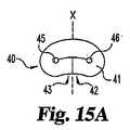
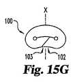
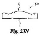
本発明のさらに別の態様では、形状記憶を有し、永久的な変形、ひび割れ、引き裂きまたは他の破壊がない状態で、包括的な短期変形が可能であるように構成された髄核インプラントが提供される。本発明の1つの形態では、インプラントは、椎間板腔に配置するようなサイズにした荷重支持弾性体を含む。弾性体は、第1端、第2端および中心部分を含み、第1端および第2端は、中心部分に隣接して折り曲げた弛緩形状で配置され、少なくとも1つの内襞を形成する。内襞は、穴を画定することが好ましい。弾性体は、椎間板線維輪の開口を通して挿入するために、真っ直ぐで弛緩せず、折り曲げられていない第2形状に変形可能である。弾性体は、椎間板腔内に配置された後に、折り曲げた形状に自動的に戻るように変形可能である。形状記憶を有するインプラントをヒドロゲル材料、または脱水できる他の親水性材料で形成する場合、インプラントは、線維輪の比較的小さい開口を通して挿入できるように、完全に、または部分的に脱水できるので有利である。開口は、例えば既存の欠陥であるか、小さい切開部を作成することによって作成することができる。 In yet another aspect of the invention, a nucleus pulposus implant configured with shape memory and capable of comprehensive short-term deformation without permanent deformation, cracking, tearing or other failure. Provided. In one form of the invention, the implant includes a load bearing elastomer sized for placement in the disc space. The elastic body includes a first end, a second end, and a central portion, and the first end and the second end are arranged in a relaxed shape bent adjacent to the central portion, and form at least one inner collar. The inner collar preferably defines a hole. The elastic body is straight and non-relaxed and can be deformed into an unfolded second shape for insertion through the opening of the intervertebral disc annulus. The elastic body can be deformed to automatically return to the folded shape after being placed in the disc space. When an implant with shape memory is formed of a hydrogel material, or other hydrophilic material that can be dehydrated, it is advantageous because the implant can be fully or partially dehydrated so that it can be inserted through a relatively small opening in the annulus fibrosus. is there. The opening can be created, for example, by making an existing defect or making a small incision.
本発明のさらに他の態様では、ロック形体および任意選択で形状記憶を有する髄核インプラントが提供される。1つの実施形態では、インプラントは、相互にはめあい係合するように構成された第1端および第2端を有する荷重支持弾性体を含む。インプラントは、第1ロック形状を有し、第1端と第2端が相互にはめあい係合する。インプラントは、椎間板線維輪の開口を通して挿入するために外力を加えることによって第2直線形状に構成することができる。インプラントが形状記憶特徴を含む場合、これは線維輪の開口を通して挿入した後、および全ての外力が除去された後に、第1ロック形状に戻るように自動的に構成するか、他の方法で戻すことができ、あるいは外力を加えることによってロック形状にすることができる。 In yet another aspect of the invention, a nucleus pulposus implant having a locking feature and optionally a shape memory is provided. In one embodiment, the implant includes a load bearing elastic body having a first end and a second end configured to matingly engage with each other. The implant has a first locking shape and the first end and the second end are matingly engaged with each other. The implant can be configured in a second linear shape by applying an external force for insertion through the opening of the disc annulus. If the implant includes a shape memory feature, it will automatically configure or otherwise return to return to the first locked shape after insertion through the annulus opening and after all external forces have been removed It can be made into a lock shape by applying an external force.
本発明の他の態様では、本発明の髄核インプラントを植え込む方法が提供される。本発明を実行する1つのモードでは、方法は、適切なインプラントを提供すること、インプラントを受けるように椎間板腔を準備すること、次にインプラントを椎間板腔に配置することを含む。インプラントが荷重支持弾性体および外部再吸収性シェルを含む場合、好ましい方法は、インプラントを受けるように椎間板腔を準備することと、インプラントの芯を形成する弾性体を、円板腔に導入することとを含み、弾性体は、円板腔内で再吸収性外部シェルによって囲まれる。再吸収性シェルを形成する材料は、弾性体の挿入前、挿入後、または挿入と同時に円板腔に配置することができる。あるいは、弾性体は、弾性体を椎間板腔に導入する前に、外部シェルで囲むことができる。 In another aspect of the present invention, a method for implanting a nucleus pulposus implant of the present invention is provided. In one mode of carrying out the invention, the method includes providing a suitable implant, preparing the disc space to receive the implant, and then placing the implant in the disc space. If the implant includes a load bearing elastic body and an external resorbable shell, a preferred method is to prepare the intervertebral disc space to receive the implant and to introduce the elastic body that forms the core of the implant into the disc space. And the elastic body is surrounded by a resorbable outer shell within the disc cavity. The material forming the resorbable shell can be placed in the disc space before, after, or simultaneously with the insertion of the elastic body. Alternatively, the elastic body can be surrounded by an outer shell prior to introducing the elastic body into the disc space.
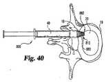
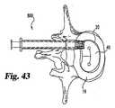
さらなる態様では、脊椎板インプラント送出装置が提供される。1つの形態では、装置は近位端、遠位端、およびそれを通って縦方向に延在する管腔を有するベース部材と、近位端および遠位端を有する複数の可動部材と、近位端および遠位端およびそれを通って縦方向に延在する管腔を有する細長部材とを含む。可動部材の近位端はベース部材の遠位端に突き当たる。ベース部材の近位端は細長部材の遠位端とはめあい係合する。さらに、可動部材は、ベース部材の管腔と連絡する空隙を画定する閉鎖形状を有する。 In a further aspect, a spinal disc implant delivery device is provided. In one form, the device includes a proximal member having a proximal end, a distal end, and a lumen extending longitudinally therethrough, a plurality of movable members having proximal and distal ends, and a proximal member. An elongated member having a distal end and a distal end and a lumen extending longitudinally therethrough. The proximal end of the movable member abuts the distal end of the base member. The proximal end of the base member is in mating engagement with the distal end of the elongate member. Further, the movable member has a closed shape that defines a gap communicating with the lumen of the base member.
本発明のさらなる態様では、上述したようなベース部材および可動部材を含む脊椎円板インプラント送出装置先端が提供される。 In a further aspect of the invention, a spinal disc implant delivery device tip is provided that includes a base member and a movable member as described above.
本発明の他の形態では、脊椎円板インプラント送出装置は、近位端、遠位端およびそれを通って長手方向に延在する管腔を有する細長いハウジング部材、および先端部材を含む。先端部材は、上壁、底壁、第1側壁、第2側壁、近位端、および遠位端を有することが有利である。先端部材の壁は、それを通って長手方向に延在する管腔を画定することが好ましい。先端部材の近位端は、細長いハウジング部材の遠位端に接続することができる。また、先端部材は、線維輪の穴を通って脊椎円板インプラントを送出するようなサイズおよび構成にされる。先端部材の管腔は、細長いハウジング部材の管腔と流体連通することが好ましい。 In another form of the invention, a spinal disc implant delivery device includes a proximal end, a distal end and an elongate housing member having a lumen extending longitudinally therethrough, and a tip member. The tip member advantageously has a top wall, a bottom wall, a first side wall, a second side wall, a proximal end and a distal end. The tip member wall preferably defines a lumen extending longitudinally therethrough. The proximal end of the tip member can be connected to the distal end of the elongated housing member. The tip member is also sized and configured to deliver the spinal disc implant through the hole in the annulus fibrosus. The lumen of the tip member is preferably in fluid communication with the lumen of the elongated housing member.
本発明の他の形態では、上壁および底壁は自身を通る開口を含み、これは先端部材の近位端から先端部材の遠位端まで延在する。 In another form of the invention, the top and bottom walls include an opening therethrough, which extends from the proximal end of the tip member to the distal end of the tip member.
椎間板腔内で移動かつ/または椎間板腔から排出されない髄核インプラント、およびそれを形成するキットを提供することが、本発明の目的である。 It is an object of the present invention to provide a nucleus pulposus implant that does not move within and / or be ejected from the disc space and a kit for forming it.
永久的な変形、ひび割れ、引き裂き、破壊または他の損傷がない状態で、包括的な短期間の手による変形、または他の変形を可能にするように構成された形状記憶を有する髄核インプラントを提供することが、本発明のさらなる目的である。 Providing a nucleus pulposus implant having a shape memory configured to allow a comprehensive short-term manual or other deformation in the absence of permanent deformation, cracking, tearing, destruction or other damage This is a further object of the present invention.
ロック形体を有する髄核インプラントを提供することが、本発明のさらに別の目的である。 It is yet another object of the present invention to provide a nucleus pulposus implant having a locking feature.
本明細書に記載された髄核インプラントを形成し、植え込む方法、さらにインプラントを植え込むための脊椎インプラント送出装置またはツールを提供することが、本発明のさらなる目的である。 It is a further object of the present invention to provide a method of forming and implanting a nucleus pulposus implant as described herein, as well as a spinal implant delivery device or tool for implanting the implant.
本発明の以上および他の目的および利点は、本明細書の説明から明白になる。 These and other objects and advantages of the present invention will become apparent from the description herein.
本発明の原理の理解を促進するために、次に好ましい実施形態を参照し、これを説明するために特定の言葉を使用する。それでも、これにより本発明の範囲を制限するものではなく、本発明のこのような変更およびさらなる改造、および本明細書で図示されたような本発明の原理のこのようなさらなる応用は、当業者に通常想定されることが理解される。 In order to facilitate an understanding of the principles of the invention, reference will now be made to preferred embodiments and specific language will be used to describe the same. Nonetheless, this does not limit the scope of the invention, and such modifications and further modifications of the present invention and such further applications of the principles of the present invention as illustrated herein are within the skill of the art. It is understood that this is normally assumed.
本発明は、人および他の動物を含む哺乳動物の自然な、または生まれつきの髄核を完全に、または部分的に置換することができる補綴椎間板髄核インプラントを提供する。本発明の1つの態様では、線維輪の欠陥または他の開口を通って排出または他の移動をせず、椎間板腔内で過度に移動しないように構成されたインプラントが提供される。特定の形態では、これらのインプラントは、注入可能/その場で硬化するインプラントと、予め形成されたインプラントとの利点を組み合わせる。例えば、髄核インプラントは、好ましくは再吸収性であるか、他の方法で一時的である外部シェルによって囲まれた荷重支持弾性体を含んでよい。外部シェルは、弾性体を椎間板腔内に係留するので有利である。弾性体の表面は、再吸収性の外部シェルへのインプラントの固定をさらに強化するために、様々なマクロ表面パターン、および本明細書に記載されたような化学または物理修飾などの様々な表面形体を含んでよい。例えばマクロ表面パターンおよび物理修飾のような表面形体は、周囲の組織への弾性体の固定も強化することが予想され、したがって本発明の特定の形態では、外部シェルが必要ないことがある。 The present invention provides prosthetic intervertebral nucleus pulposus implants that can fully or partially replace the natural or native nucleus pulposus of mammals, including humans and other animals. In one aspect of the invention, an implant is provided that does not expel or otherwise move through an annulus defect or other opening and that does not move excessively within the disc space. In a particular form, these implants combine the advantages of injectable / in situ hardening implants with preformed implants. For example, a nucleus pulposus implant may include a load bearing elastic surrounded by an outer shell that is preferably resorbable or otherwise temporary. The outer shell is advantageous because it anchors the elastic body within the disc space. The surface of the elastic body has various macro surface patterns and various surface features such as chemical or physical modifications as described herein to further enhance the anchoring of the implant to the resorbable outer shell. May be included. Surface features such as macro surface patterns and physical modifications are also expected to enhance the anchoring of the elastic body to the surrounding tissue, and therefore in certain forms of the invention an external shell may not be necessary.
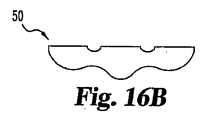
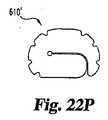
本発明の他の態様では、形状記憶を有し、永久的な変形、ひび割れ、引き裂き、破壊または他の損傷がない状態で、包括的で短期的な手による変形または他の変形が可能であるように構成された髄核インプラントが提供される。インプラントをヒドロゲルまたは他の親水性材料から形成する本発明の好ましい形態では、インプラントは線維輪の比較的小さい切開部を通過できるばかりでなく、椎間板腔を十分に充填し、それに一致することもできる。本発明の1つの形態では、インプラントは、少なくとも1つの内襞を形成するために中心部分に隣接して配置された第1および第2端を有する形状記憶の荷重支持弾性体を含む。内襞は、穴または通路を画定することが望ましい。 In another aspect of the invention, comprehensive short-term manual or other deformation is possible with shape memory and without permanent deformation, cracking, tearing, breaking or other damage. A nucleus pulposus implant configured as described above is provided. In a preferred form of the invention in which the implant is formed from a hydrogel or other hydrophilic material, the implant can not only pass through a relatively small incision in the annulus, but can also fully fill and conform to the disc space. . In one form of the invention, the implant includes a shape memory load bearing elastic body having first and second ends disposed adjacent to the central portion to form at least one internal collar. The inner collar desirably defines a hole or passage.
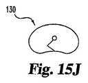
本発明の他の実施形態では、形状記憶インプラントは、円板腔内で螺旋状または他の環状形状を形成するように構成され、インプラントを円板空隙内にさらに固定するために、相互にはめあい係合する端部を有するように構成してもよい。本明細書に記載されたインプラントを作成し、植え込む方法も提供される。 In other embodiments of the present invention, the shape memory implants are configured to form a spiral or other annular shape within the disc cavity and fit together to further secure the implant within the disc space. You may comprise so that it may have an edge part to engage. Also provided are methods of making and implanting the implants described herein.
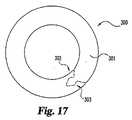
上記で開示されているように、本発明の第1の態様では、椎間板腔に導入されるようなサイズであり、好ましくは再吸収性の外部シェルによって囲まれた荷重支持弾性体を含む髄核インプラントが提供される。次に図1および図2を参照すると、補綴インプラント10は、椎体21と22の間の椎間板腔20に配置され、外部シェル30に囲まれた芯の荷重支持弾性体15を含む。特に、弾性体15は、再吸収性であるか、他の方法で一時的であると有利である外部シェル30と接触し、好ましくはそれに結合される外面16を有する。外部シェル30の外面31は、椎間板空隙20の形状と一致し、線維輪5と接触し、図1および図2で見られるように弾性体15を完全に囲めることが好ましいが、外部シェル30は弾性体15を一部しか囲まなくてもよい。一例として、弾性体15を囲む上、下および/または横の空所は、円板空隙内からの排出、または円板空隙内での過度の移動を防止するように、弾性体が何らかの方法で外部シェルによって係留されるか、他の方法で所定の位置に固定されている限り、外部シェル30によって充填することができる。したがって、外部シェル30は上記の空所を充填するように構成できる。また、外部シェル30の内面32は、弾性体15の形状と一致することが好ましく、以下で検討するように弾性体15の外面16に結合することが好ましい。好ましい実施形態では、弾性芯および外部シェルは、以下でさらに検討するように円板空隙をほぼ充填する。 As disclosed above, in a first aspect of the present invention, the nucleus pulposus is sized to be introduced into an intervertebral disc space and preferably includes a load bearing elastic body surrounded by a resorbable outer shell. An implant is provided. Referring now to FIGS. 1 and 2, the
外部シェル30は、過度に移動しないよう固定するために、周囲円板組織へのインプラント表面の最大耐力、応力伝達、および結合のために椎間板腔20内に適切に嵌合するインプラント10を提供するばかりでなく、インプラントの移動および/または排出にさらに対抗するために環状欠陥18の密封も行う。このような環状欠陥の密封は、円板に追加の物理的および機械的支持も提供することができる。さらに、注入可能な外部シェル材料は、インプラント10の芯弾性体を円板腔内に取り付ける際に手術中柔軟性を提供することができる。というのは、円板腔と予め形成された芯との間の幾何学的形状およびサイズの違いを補償できるからである。 The
外部シェル30は再吸収可能であることが好ましく、このような形態では、荷重支持弾性体を円板腔内に永久的に閉じ込めるのを補助することができる線維組織および線維瘢痕組織を含むような組織で置換することが好ましい。次に図3および図4を参照すると、組織33は外部シェル30を置換しており、したがって弾性体15を囲んでいる。弾性体15は、組織33の助けで円板腔内に限定することができるが、弾性体15は正常な生体力学のせいで多少の可動性を有することが予想される。 The
荷重支持弾性体15の寸法は、特定のケースに応じて変化してよいが、弾性体15は通常、椎間板腔に導入するようサイズ決定される。さらに、弾性体15は、隣接椎骨を支持するのに十分なほど広く、隣接する椎骨を分離するのに十分な高さであることが好ましい。椎間板に長期的な機械的支持を提供するために、円板腔内の弾性体15の体積は、円板腔全体の体積の少なくとも約50%、好ましくは少なくとも約70%、さらに好ましくは少なくとも約80%、およびより好ましくは少なくとも約90%でなければならず、残りの体積は外部シェル30によって占有される。しかし、弾性体15の体積は、椎間板腔の体積の約99%もあってよく、したがってインプラント10の体積の約99%であってよい。したがって、外部シェル30の体積は、インプラントの体積の少なくとも約1%でよいが、約1%から約50%の範囲でよい。特定のケースで望ましいインプラント10の適切なサイズは、自然の髄核の所望の部分および自由な円板破片を全て除去した後に、円板腔を所望のレベルまで伸延させ、注入可能な食塩水バルーンで延伸腔の体積を測定することによって求めることができる。円板の体積は、最初に既知の量の外部シェル先駆物質で円板腔を充填することにより、直接測定することもできる。 The dimensions of the load bearing
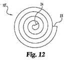
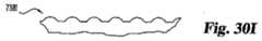
弾性体15は、弾性体が脊椎の負荷および他の脊椎の応力に耐えられる限り、所望に応じて多種多様な形状で作成することができる。非分解性で予備形成した弾性体15を、例えば円筒形または長方形ブロックとして成形することができる。弾性体はさらに環形でもよい。例えば、図12および図13のインプラント10’は螺旋状または他のコイル状の形状を有する。インプラントは第1端23および第2端24を含む。弾性体15は、自然の髄核の形状と全体的に一致するように成形するか、以下でさらに説明するように成形してもよい。弾性体15は、例えば図1から図4では一体品として図示されているが、1つまたは幾つかの部片から作成してよい。 The
弾性体15は、エラストマ材料、ヒドロゲルまたは他の親水性ポリマ、またはこれらの複合物などの弾性材料を含む多種多様な生体適合性ポリマ材料から形成することができる。適切なエラストマはシリコン、ポリウレタン、シリコンとポリウレタンの共重合体、ポリイソブチレンおよびポリイロプレンなどのポリオレフィン、ネオプレン、ニトリル、加硫ゴムおよびこれらの組合せを含む。本明細書に記載された加硫ゴムは、例えば1−ヘキセンおよび5−メチル−1,4−ヘキサジエンから例えばサマーズ(Summers)等の米国特許第5,245,098号に記載されているように生産された共重合体を使用して、加硫プロセスなどで生産することができる。適切なヒドロゲルは天然ヒドロゲル、およびポリビニルアルコール、ポリアクリル酸およびポリ(アクリロニトリルアクリル酸)のようなアクリルアミド、ポリウレタン、ポリエチレングリコール、ポリ(N−ビニル−2−ピロリドン)、ポリ(2−ヒドロキシエチルメタクリレート)およびアクリレートとN−ビニルピロリジンの共重合体のようなアクリレート、N−ビニルラクタム、アクリルアミド、ポリウレタンおよびポリアクリロニトリルを含むか、ヒドロゲルを形成する他の同様の材料でよい。ヒドロゲル材料はさらに架橋結合して、インプラントにさらなる強度を提供することができる。ポリウレタンの例は、熱可塑性ポリウレタン、脂肪族ポリウレタン、分割されたポリウレタン、親水性ポリウレタン、ポリエーテルウレタン、ポリカーボネートウレタンおよびシリコンポリエーテルウレタンを含む。他の適切な親水性ポリマは、グルコマンナンゲル、ヒアルロン酸、架橋結合したカルボキシを含む多糖類などの多糖類、およびこれらの組合せのような自然に発生する材料を含む。弾性体の形成に使用する材料の性質は、形成されたインプラントが十分な耐力を有するように選択しなければならない。好ましい実施形態では、少なくとも約0.1Mpaの圧縮強さが望ましいが、約1Mpaから約20Mpaの範囲の圧縮強さがさらに好ましい。 The
外部シェル30は、多種多様な生体適合性、好ましくは弾性、エラストマまたは変形可能な天然または合成材料、特に弾性体15と適合性である材料から形成することができる。外部シェル材料は、弾性体を椎間板腔に配置する間、未硬化、変形可能、または他の形成可能な状態のままであることが好ましく、椎間板腔内に導入した後に、または他の実施形態では、弾性体を椎間板腔内に配置する前に、好ましくは急速に硬化するか、硬くなる、または好ましくは固化しなければならない。好ましい実施形態では、外部シェル材料は、硬化するか、他の方法で固化した後に変形可能なままでよい。外部シェルの形成に使用できる適切な材料は、天然または合成材料から作成した組織密封材または接着剤を含み、例えば繊維素、アルブミン、コラーゲン、エラスチン、絹および他のタンパク質、ポリエチレンオキサイド、シアノアクリル酸塩、ポリアクリレート、ポリ乳酸、ポリグリコール酸、フマル酸ポリプロピレン、チロシン系ポリカーボネートおよびこれらの組合せを含む。他の適切な材料は鉱物質除去した骨基質を含む。これらの先駆物質材料は、液体、溶液または固体形態で供給することができ、これはゲル形態を含む。 The
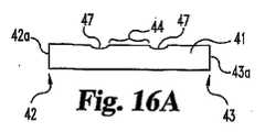
弾性体15は、弾性体の外面16と外部シェル30の内面32との結合を都合よく改善する表面形体を提供するように、化学修飾および表面形状を含む様々な表面形体を外面16上に含んでよい。本発明の一形態では、外面16は、例えば外部シェル30の形成に使用した材料と適合性である化学基を使用して化学修飾される。適切な化学修飾は、例えばヒドロキシ、アミノ、カルボキシ、および器官官能シラン基を含む反応性官能基の表面移植を含む。基は、当業者に知られている方法で移植することができる。他の修飾は、接着剤の層、シールまたは上述した外部シェルの形成に使用される他の材料など、外部シェル材料と適合性であることが好ましいプライマで予め被覆することを含む。 The
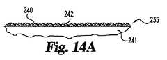
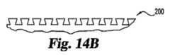
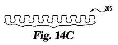
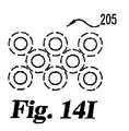
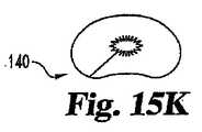
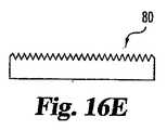
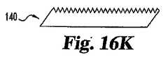
本発明のさらに別の形態では、弾性体15は、様々な表面形体がある弾性体の上部分の側面図または上面図を示す図14Aから図14Jで見られるように、マクロ表面パターンまたは突起などの多種多様な表面形状を含むことができる。次に図14Aから図14Jを参照すると、パターンは鳩尾形パターン200、円形パターン205、矩形パターン210、円錐形パターン215、様々な波パターン220および225、および不規則なランダムパターン230でよい。他の実施形態では、線維240を弾性体241内に配置し、その表面242から突出させて、線維パターン235を形成することができる。線維240は、弾性体の表面から突出するループとして配置し、その端部が弾性体の表面から突出するか、線維が多種多様な他の適切な形状を有してよい。線維は、約1インチ未満に切断した線維のように、短いポリマ線維でよい。あるいは、線維は連続的なポリマ線維でよい。線維はさらに編んでもよく、織物または不織物でもよい。マクロ表面パターンは、弾性体15の形成中に形成することが好ましい。しかし、弾性体15の外面16は、弾性体15の形成後に、例えばレーザドリリングまたは熱変形によって物理的に修飾してもよい。物理的修飾は、例えばビード吹き付け、プラズマエッチングまたは化学的エッチングによって形成した微細構造表面を含む。この方法で様々な表面を修飾する手順は、当技術分野でよく知られている。 In yet another form of the invention, the
本発明の特定の形態では、インプラントは、上述したような1つまたは複数の外面形体を有する弾性体15のみを含み、再吸収性外部シェルがなくてよい。表面形体が、移動および/または排出に対する抵抗を改善するために、周囲組織への特定レベルの固定を提供すると予想される。 In a particular form of the invention, the implant may include only an
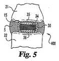
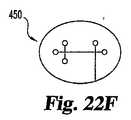
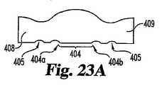
本発明のさらに他の形態では、インプラントは、支持または他の方法で制約する部材によって囲まれた弾性体を含んでよく、支持部材は本明細書に記載されているように再吸収性シェルに囲まれる。次に図5を参照すると、インプラント400は、支持部材34に囲まれた荷重支持弾性体15を含む。1つの形態では、支持部材34は、図5で見られるように弾性体15の周囲に配置され、好ましくは可撓性の周囲支持帯でよく、弾性体15の上面および下面35および36それぞれには支持帯がないままである。 In yet another form of the invention, the implant may include an elastic body surrounded by a support or other constraining member, the support member being a resorbable shell as described herein. Surrounded. Referring now to FIG. 5, the
図5で見られるように、弾性体15の上面および下面35および36それぞれの一部は露出し、外部シェル30に直接接触する。この露出は、支持部材の構築に必要な材料の量を最小限に抑えるが、それでも例えば横方向の支持を効果的に提供する。露出した弾性体15の上面および下面の量は変動してよいが、通常は表面の少なくとも約50%、好ましくは少なくとも約70%、さらに好ましくは少なくとも約80%、最も好ましくは少なくとも約90%が露出する。 As seen in FIG. 5, a portion of each of the upper and
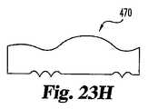
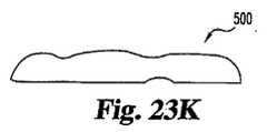
図6に示したさらに別の実施形態では、上述したような弾性体15を含む髄核インプラント500は、ジャケットの形態をとる支持部材37で強化される。ジャケットは、弾性体15を完全に囲むことが好ましい。 In yet another embodiment shown in FIG. 6, a
強化外帯、カバー、または他のジャケットを含む適切な支持部材は、多種多様な生体適合性ポリマ、金属材料、または圧縮性負荷が増加しても芯の横方向(水平)変形を含む過度な変形を防止するために、強力であるが可撓性の支持体を形成する材料の組合せから形成することができる。適切な材料は、繊維素、ポリエチレン、ポリエステル、ポリビニルアルコール、ポリアクリロニトリル、ポリアミド、ポリテトラフルオロエチレン、ポリパラフェニレン、テレフタルアミド、およびこれらの組合せを含むポリマ線維から作成した織る、織っていない、編んだ、またはファブリック材料を含む。他の適切な材料は、シリコン、ポリウレタン、シリコンとポリウレタンの共重合体、ポリイソブチレンおよびポリイソプレンを含むポリオレフィン、ネオプレン、ニトリル、加硫ゴム、およびこれらの組合せのような非強化または繊維強化エラストマを含む。本発明の好ましい形態では、シリコンおよびポリウレタンの組合せまたは混合物を使用する。さらに、加硫ゴムは、髄核インプラントについて上述した通りに生産することが好ましい。支持部材34および37は、多孔質材料から作成すると有利であり、これはヒドロゲルまたは他の親水性材料から作成した弾性体の場合、弾性芯体を通って流体を循環させ、椎間板の給送作用を強化することができる。支持部材はさらに、炭素繊維ヤーン、セラミック繊維、金属繊維、または例えば米国特許第5,674,295号に記載されたような他の同様の繊維から形成することができる。 Suitable support members including reinforced outer bands, covers, or other jackets are excessive, including a wide variety of biocompatible polymers, metallic materials, or lateral (horizontal) deformations of the core as the compressive load increases. To prevent deformation, it can be formed from a combination of materials that form a strong but flexible support. Suitable materials are woven, non-woven, knitted made from polymer fibers including fibre, polyethylene, polyester, polyvinyl alcohol, polyacrylonitrile, polyamide, polytetrafluoroethylene, polyparaphenylene, terephthalamide, and combinations thereof Or include fabric material. Other suitable materials include non-reinforced or fiber reinforced elastomers such as silicone, polyurethane, silicone and polyurethane copolymers, polyolefins including polyisobutylene and polyisoprene, neoprene, nitriles, vulcanized rubber, and combinations thereof. Including. In a preferred form of the invention, a combination or mixture of silicon and polyurethane is used. Furthermore, the vulcanized rubber is preferably produced as described above for nucleus pulposus implants. The
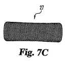
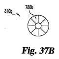
図7Aから図7Dは、上述したように通常は様々な編み材料(支持帯25、26および27)または多孔質材料(支持帯28)から作成された様々なパターンの支持帯を示す。ジャケットもこのようなパターンで形成してよいことも理解される。編み材料は多孔質でもよいことが認識される。 7A-7D show various patterns of support bands, typically made from various knitted materials (
支持部材34および37は、支持部材がないインプラントの変形と比較して、所望通りに横方向の変形を減少させることが好ましい。支持部材34および/または37は、例えば少なくとも約20%、好ましくは少なくとも約40%、さらに好ましくは少なくとも約60%、最も好ましくは少なくとも80%横方向の変形を減少させることができる。弾性体を含むインプラントのように、このような支持部材を有するインプラントは可撓性で、かつ他の方法で弾性であり、円板を自然に動作できるようにし、小さい印加応力または中位の印加応力に対して衝撃吸収能力を提供するが、高応力状態では円板の高さを維持するために過度に変形しにくい。例えば腰椎円板のケースで本明細書で記載されているように、低い印加応力は約100ニュートンから約250ニュートンの力を含み、中位の応力は約250ニュートンから約700ニュートンの力を含み、高い負荷状態、または高応力は約700ニュートンより大きい力を含む。本発明の好ましい形態では、支持部材は折り曲げるか、他の方法で変形できるが、実質的に非弾性であるという点で可撓性であり、したがってインプラントはさらに十分に強化または他の方法で支持される。
弾性体をジャケット支持部材で覆うか、帯支持部材を弾性体の周囲に巻き付けることができる。弾性体がヒドロゲル、または同様の親水性材料から形成される本発明の形態では、ヒドロゲルは、ジャケットで覆う前、またはヒドロゲル体の周囲に帯を巻き付ける前に、所望の量だけ脱水することができる。ヒドロゲル弾性体は、体外の食塩水に曝露するか、円板腔に挿入することができ、ここでその場で体液に曝露し、体が水を吸収して膨張する。周囲帯支持部材に関して、水平方向でのヒドロゲル弾性体の膨張または拡大は、支持帯内に設計された遊びの量で制御される。許容水平拡張の限界に到達した後、弾性体は、体内負荷がある状態で平衡膨張状態に到達するまで、大部分は垂直方向に強制的に拡大される。弾性体の上面および下面は実質的に限定されていないので、垂直方向の拡大は主に、印加応力およびヒドロゲル材料の挙動によって制御される。 The elastic body can be covered with a jacket support member, or the belt support member can be wound around the elastic body. In the form of the invention where the elastic body is formed from a hydrogel or similar hydrophilic material, the hydrogel can be dehydrated by a desired amount before being covered with a jacket or before wrapping a band around the hydrogel body. . The hydrogel elastomer can be exposed to extracorporeal saline or inserted into the disc cavity where it is exposed to bodily fluids in situ where the body absorbs water and swells. With respect to the surrounding band support member, the expansion or expansion of the hydrogel elastomer in the horizontal direction is controlled by the amount of play designed in the support band. After reaching the limit of allowable horizontal expansion, the elastic body is largely forcibly expanded in the vertical direction until it reaches an equilibrium inflated state with a body load. Since the upper and lower surfaces of the elastic body are not substantially limited, the vertical expansion is mainly controlled by the applied stress and the behavior of the hydrogel material.
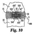
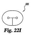
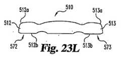
本発明のさらに他の形態では、再吸収性外部シェルで囲まれた上述通りの周囲支持帯で強化されたインプラントは、1つまたは複数のストラップでさらに強化することができる。ストラップは、本明細書に記載された周囲支持帯がずれるか、他の方法で滑動してインプラントから外れるのを防止する上で有利である。次に図8および図9を参照すると、少なくとも1つのストラップ420がインプラント400の弾性体15の上面35に沿って延在し、少なくとも1つのストラップ430が下面36に沿って延在する。ストラップ420の端部421およびストラップ430の端部431はそれぞれ、周囲支持帯34’に接続するか、他の方法で取り付けることが好ましい。取り付け点はストラップを固定する任意の位置でよく、支持帯の上部マージン138、支持帯の下部マージン139、または上部マージンと下部マージンの間の任意の領域を含む。図8および図9では上面35および下面36それぞれに沿って延在する2つのストラップ420および430が図示されているが、インプラントの全周に延在する1つの連続的ストラップを使用するか、ストラップの組合せが支持帯の過度の滑動および/またはずれを防止するのに十分である限り、使用ストラップは1つ、2つまたは複数の部片でよい。さらに、例えばストラップ520、530、540および550は、支持部材34”に取り付けられるか、他の方法で接続した状態で図示されているインプラント500の図10および図11で見られるように、複数のストラップが弾性体15の上面35に沿って延在し、複数のストラップが下面36に沿って延在してよい。ストラップは1つまたは複数の部片であってよいことが認識される。例えば、ストラップ520および530は、ストラップ540および550のように単一のストラップを形成するか、全てを組み合わせて単一のストラップを形成することができる。 In yet another aspect of the invention, an implant reinforced with a peripheral support band as described above surrounded by a resorbable outer shell can be further reinforced with one or more straps. The strap is advantageous in preventing the perimeter support bands described herein from slipping or otherwise slipping out of the implant. 8 and 9, at least one
本発明の他の態様では、上述した外部シェルを含む椎間板髄核インプラントを形成するよう設計されたキットが提供される。1つの形態では、キットは、好ましくは再吸収性の外部シェルを形成する材料の容器とともに、上述したような荷重支持弾性体を含んでよい。材料は、上述したような材料から選択してよい。さらに、シェルを形成する材料を収容する容器は、ガラスおよびプラスチックなど、外部シェル材料と適合性である多種多様な材料から作成してよい。キットはさらに、支持帯、ジャケット、または上述したような他の外部カバーのような支持部材を含んでよい。通常、キットは、キットの取り扱い中に構成要素の損傷を防止するために、キット構成要素を相互から十分隔置した関係で固定する殺菌包装を含む。例えば、キット構成要素を隔置した関係で保持する複数の区画または他の区域を有する、当技術分野で知られている成形プラスチック品を使用してよい。 In another aspect of the invention, a kit is provided that is designed to form an intervertebral nucleus pulposus implant that includes the outer shell described above. In one form, the kit may include a load bearing elastic as described above, preferably with a container of material forming a resorbable outer shell. The material may be selected from materials as described above. Further, the containers that contain the material forming the shell may be made from a wide variety of materials that are compatible with the outer shell material, such as glass and plastic. The kit may further include a support member such as a support band, jacket, or other outer cover as described above. Typically, the kit includes a sterilization package that secures the kit components in a sufficiently spaced relationship from each other to prevent damage to the components during handling of the kit. For example, molded plastic articles known in the art may be used that have multiple compartments or other areas that hold the kit components in spaced relationship.
本発明のさらなる態様では、例えばインプラントを椎間板腔内に配置する間に生じるような永久的な変形、ひび割れ、引き裂き、破壊または他の損傷がない状態で、包括的な短期間の手による変形、または他の変形を可能にするように構成された形状記憶を有する髄核インプラントが提供される。次に図15Aおよび図16Aを参照すると、本発明の1つの形態では、インプラント40は、少なくとも1つの内襞45を形成するように中心部分44に隣接して配置された第1端42および第2端43を有する形状記憶を備えた荷重支持弾性体41を含む。内襞45は、少なくとも1つの穴46を画定することが好ましく、これは弓形であると有利である。弾性体は、椎間板腔内に配置するために、例えば図15Aで示したこの折り曲げるか、他の方法で弛緩した第1形状から、図16に示したほぼ直線、または他の弛緩していない第2形状へと手動で変形可能であるか、他の方法で構成可能である。弾性体41が形状記憶を有するので、手による力または他の力が弾性体に加えられなくなると、折り曲げて弛緩した第1形状へと自身で自動的に戻る。したがって、これらのインプラントは、インプラントを破壊したり、他の方法で損傷したりせずに、個人が変形、構成および他の方法で取り扱うことができるという点で、改善された取り扱いおよび操作特性を提供する。 In a further aspect of the invention, a comprehensive short-term manual deformation, or other, without permanent deformation, cracking, tearing, destruction or other damage, such as occurs during placement of the implant in the disc space. A nucleus pulposus implant having a shape memory configured to allow for deformation of the nucleus is provided. Referring now to FIGS. 15A and 16A, in one form of the invention, the
形状記憶の補綴核インプラント40についてさらに説明すると、インプラント40は表面窪み47、または以下でさらに詳細に説明するような他の表面凹凸を含み、これはインプラントが弛緩した形状である場合に内襞45を形成する。端部42および43はそれぞれ端面42aおよび43aを有し、これは全体的に平坦であり、弛緩した形状でインプラントの幅を通る軸Xに対してほぼ平行であるか、他の形態では垂直であり、端部は図15A、図15Bおよび図15Eから図15Nで見られるように相互に突き当たってよい。インプラントの端部はそれぞれ、図15Cおよび図15Dのインプラント60および70について示すように、インプラントの中心部分と交互に突き当たって、全体的に二葉または双眼鏡の形状のインプラントを形成する。 Further describing the shape memory
あるいは、本発明の他の形態では、インプラントの一方端を先細にするか、他の方法で特定の形状にし、他方端を、先細または他の形状の端部に対して相補的に成形することができる。さらに、髄核インプラントの端部の片側または両側96aおよび96bを先細にしてよい。例えば、図15Fおよび図16Fに見られるように、インプラント90の端部93の両側を先細にして、全体的にV字形の端部のような尖った端部を形成し、これは端部92によって画定された相補的形状の(例えばV字形の)窪み95に嵌るので有利である。1つの穴を画定する1つだけの内襞、および端部92および93のように同様に構成された端部を有するインプラントが、図15Jおよび図16Jに図示されている。別の実施例として、インプラントの各端部の片側を、図15Gおよび図16Gに見られるものとは反対に先細にしてよい。つまり、インプラント100の端部102の側部108aおよび端部103の反対側109bは、図15Gおよび図16Gに見られるように先細になる。インプラント100の端面102aおよび102bは、インプラントが図15Gに示す弛緩形状にある場合に、軸Xに対して横方向である。インプラントの端部が先細である、または他の方法で成形されたこれらの実施形態では、インプラントの端部が相互に、またはインプラントの中心または他の部分に接触すると、接触領域を通してインプラントの長さに沿って一様であるインプラントが形成されることが好ましい。 Alternatively, in another form of the invention, one end of the implant is tapered or otherwise shaped to a specific shape and the other end is shaped complementary to the tapered or other shaped end. Can do. In addition, one or both
インプラントは多種多様な形状になることができるが、通常は折り曲げた弛緩形状にて、自然の髄核の形状と一致するように成形される。したがって、インプラントは、本発明の幾つかの形態では折り曲げた弛緩形状である場合に、ほぼ楕円形でよい。本発明のさらなる形態では、折り曲げた形状のインプラントの形は、全体的に環形であるか、椎間板空隙に一致するように必要に応じて他の形状でもよい。さらに、ほぼ直線の形状であるように、インプラントが折り曲げず、弛緩していない形状である場合、これは多種多様な形状になることもできるが、最も好ましくは全体的に細長く、好ましくは全体的に円筒形であるが、本明細書に記載されたような他の形状である。 Implants can come in a wide variety of shapes, but are usually folded in a relaxed shape and shaped to match the shape of the natural nucleus pulposus. Thus, the implant may be generally oval when in some forms of the invention is a folded relaxed shape. In a further form of the invention, the shape of the folded shaped implant may be generally annular or other shapes as required to match the disc space. Furthermore, if the implant is a non-bent and unrelaxed shape, such as a generally straight shape, this can be a wide variety of shapes, but most preferably is generally elongated, preferably overall. But are other shapes as described herein.
本発明のさらに他の形態では、折り曲げたインプラントは、上述したように永久的な変形または他の損傷がない状態で、インプラントを短期的に変形可能にすることをさらに補助する表面突起を含む表面を有してよい。次に図15Dおよび図16Dを参照すると、インプラント70は、第1端72、第2端73および中心部分74を有する荷重支持弾性体71を含む。内襞75は穴76を画定し、自身上にしわまたは突起78を有する内襞表面77を含む。内襞表面77の突起78は穴76内に延在する。これらのしわは、椎間板腔に挿入するためにインプラントを真っ直ぐにするか、伸張した場合に、変形、ひび割れ、引き裂き、破壊、または他の損傷がない状態でインプラントの伸張を促進するので有利である。図15Dおよび図16Dに示した実施形態では、しわ、または表面突起は、中心部分74を含む弾性体71の全長に沿って延在する。しわがある内襞表面を有する他のインプラントが、図15Eおよび図16Eに見られ、インプラントを折り曲げた後の他のしわ形状が、図15Kから図15Nおよび図16Kから図16Nに見られる。 In yet another aspect of the invention, the folded implant includes a surface protrusion that further assists in making the implant deformable in the short term in the absence of permanent deformation or other damage as described above. May be included. Referring now to FIGS. 15D and 16D, the
他の折り曲げたインプラントが、図22Aから図22Q、図23Aから図23Qおよび図24から図27に図示されている。これらの図を参照すると、例えば2個から約6個の範囲の複数の内襞を有するインプラント400〜620が図示されている。さらに、これらのインプラント、および上述した折り曲げたインプラントは、インプラントの第1および第2アームそれぞれから形成した第1および第2端を有する。例えば図22Aおよび図23Aに見られるように、インプラント400の第1端402は、中心部分404の一方端404aに接続されるか、他の方法でそれに関連する第1アーム408から形成される。第2端403は、中心部分404の反対端404bと接続するか、他の方法でそれに関連する第2アーム409から形成される。表面窪み405または他の表面凹凸は、インプラントが弛緩形状である場合に、内襞406を画定する。 Other folded implants are illustrated in FIGS. 22A-22Q, FIGS. 23A-23Q and FIGS. 24-27. Referring to these figures, implants 400-620 having a plurality of internal ridges, for example, ranging from 2 to about 6, are illustrated. In addition, these implants, and the folded implants described above, have first and second ends formed from the first and second arms of the implant, respectively. For example, as seen in FIGS. 22A and 23A, the
本発明の特定の形態では、インプラントの中心部分に接続された各アームは、図15Aから図15J、図15Lから図15N、図22Aから図22B、図23Aから図23B、図22Dから図22E、図23Dから図23E、図22Gおよび図23Gに見られるように、同じ長さである。本発明のさらに他の形態では、アームの一方が他方のアームより短い。例えば図22Cに見られるように、インプラント420の第2アーム429は第1アーム428より短く、各アームは中心部分424の端部に接続される。言い換えると、本発明の特定の形態では、インプラントの端部は、軸Xに沿って延在してインプラントの幅を通る面に沿って相互に突き当たり、その結果、例えば図22Aに見られるようなインプラントの中心または中心閉鎖部Cになる。本発明の他の形態では、インプラントの端部は、軸Xに沿って延在する面に平行に延在し、インプラントの幅を通る面に沿って相互に突き当たり、その結果、例えば図22Cに見られるようなインプラントの中心からずれた閉鎖部C’になる。インプラントのアームの長さの差は、以下でさらに詳細に説明するように、円板腔へのインプラントの植え込みおよび適切な配置を促進することができる。 In particular forms of the invention, each arm connected to the central portion of the implant is shown in FIGS. 15A-15J, 15L-15N, 22A-22B, 23A-23B, 22D-22E, As seen in FIGS. 23D through 23E, 22G and 23G, they are the same length. In yet another aspect of the invention, one of the arms is shorter than the other arm. For example, as seen in FIG. 22C, the
さらに、インプラントの内襞の幾つかは、インプラントの第1端と第2端が、例えば図22Cに見られるように相互に接触するか、他の方法で突き当たった場合に形成することができる。本発明のこのような形態では、インプラントの各端は、図23Cに見られるような表面窪み421または422などの表面窪みを有する表面を含んでよく、これは内襞の一部を形成し、したがってインプラントの端部が相互に接触すると、表面窪みの組合せから内襞が形成される。また、内襞によって画定された穴は、ほぼ環状またはそれ以外の輪形、ほぼ楕円またはそれ以外の長円形、星形または当業者に知られた他の様々な形状を含む様々な断面形状を有してよい。星形パターンは、例えば図22Gおよび図22Hそれぞれに見られるような複数の指状またはそれ以外の細長い突起465または475を含む。 In addition, some of the implant's inner ridges can be formed when the first and second ends of the implant are in contact with each other or otherwise struck, as seen, for example, in FIG. 22C. In such a form of the invention, each end of the implant may include a surface having a surface depression, such as a
図22I、図23I、図24、図22K、図23Kおよび図26は、本発明のインプラントのさらなる詳細を示す。例えば、それぞれインプラント480および500を示す図24および図26それぞれには穴または通路486および506が見られる。次に図22J、図23Jおよび図25を参照すると、荷重支持体491、第1端492を有する第1アーム498、第2端493を有する第2アーム499、および表面窪み497など、前述したインプラントの形体を全て含むインプラント490が図示されている。また、インプラント490は、インプラントの一方端からインプラントの反対縁までインプラント490の全幅に沿って延在する中心部分494を含む。このような実施形態では、インプラント490が図22Jで見られるように折り曲げた形状にある場合、端面492aおよび493aが中心部分494と突き当たり、それ以外はこれと接触する。 Figures 22I, 23I, 24, 22K, 23K, and 26 show further details of the implant of the present invention. For example, holes or
本発明の1つの形態では、インプラントの少なくとも一方の端が湾曲するか、それ以外の弓形の形または丸まっていてよい。図22Lおよび図23Lのインプラント510を参照すると、第1端512および第2端513はそれぞれ、内縁512bおよび513b、および外縁512aおよび513aをそれぞれ有する。外縁512aおよび513aは丸まった状態で図示され、以下でさらに詳細に説明するように、円板腔へのインプラントの植え込みおよび適切な配置を促進することができる。 In one form of the invention, at least one end of the implant may be curved, otherwise arcuate or rounded. Referring to the
例えば、丸まった縁部は、円板腔へのインプラントのよりよい一致を可能にする。理論によって制限されてはいないが、ドーム形またはそれ以外の凹形の終板は、インプラントの縁部に集中する応力の増大につながり得る。丸まった縁部は、このような応力を減少させる。この方法で、インプラントが終板を貫通する可能性が低下し、インプラントの耐久性が改善される。インプラントの形状に基づく骨の再造形も減少させる。 For example, a rounded edge allows a better match of the implant to the disc space. Without being limited by theory, a dome-shaped or otherwise concave endplate can lead to an increase in stress concentrated at the edge of the implant. A rounded edge reduces such stress. In this way, the likelihood that the implant will penetrate the endplate is reduced and the durability of the implant is improved. Bone remodeling based on the shape of the implant is also reduced.
図22Mおよび図23Mを参照すると、インプラントの量端が湾曲するか、他の丸まった縁部を有するインプラント610が図示されている。インプラント610は、第1アーム613および第2アーム614を有する体611を含む。第1アーム613および第2アーム614は、それぞれ端部613aおよび614aを含み、これは両方とも丸まった縁部613bおよび614bをそれぞれ有することが好ましいが、端部の一方のみがこのように丸まった縁部、直線の縁部または他の形状の縁部を有してもよい。この実施形態では、第1アーム614の端部614aは先細にされるか、他の状態で第1アーム613の端部613aと比較して小さい直径を有する。また、第1アーム613は第2アーム614より短い。 Referring to FIGS. 22M and 23M, an
図22Nから図22Q、図23Nから図23Qおよび図27を参照すると、上述の折り曲げたインプラントの代替実施形態が図示されている。全てのインプラントと同様に、インプラントを形成する弾性体は、例えば図27に見られるように椎間板の上部椎骨終板と接触する上面T、および椎間板の下部椎骨終板と接触する底面Bを有する。また、インプラントは、側面に沿って延在する少なくとも1つの溝Gを含む外部側面Eを有し、これはインプラントが変形してほぼ真っ直ぐになるか、他の折り曲げない形状になった場合に、インプラントの外部側面Eにかかる圧縮力をさらに緩和し、したがって永久的な変形、ひび割れ、引き裂きまたは他の破損がない状態で、包括的な短期の変形をさらに可能にするので有利である。例えば、図22N、図23Nおよび図27に図示されたインプラント620は、上面T、底面B、内部側面Iおよび外部側面Eを有する荷重支持体621を含む。複数の溝Gが外部側面Eに沿って配置され、これは通常、インプラントの上面から底面へと延在する。インプラントを半分に分割し、したがって軸Xに沿ってインプラントの幅を通る面で第1側S1および第2側S2をさらに容易に見えるようにすると、図22Nでは、第1側S1に4つの溝Gが存在し、第2側S2には4つの溝Gが存在することが分かるが、場合に応じて異なる数が存在してもよい。各側S1およびS2には少なくとも1つの溝が存在することが好ましい。Referring to FIGS. 22N-22Q, 23N-23Q, and 27, an alternate embodiment of the folded implant described above is illustrated. As with all implants, the elastic body forming the implant has a top surface T that contacts the upper vertebral endplate of the intervertebral disc and a bottom surface B that contacts the lower vertebral endplate of the intervertebral disc, as seen, for example, in FIG. The implant also has an outer side E that includes at least one groove G that extends along the side, which is when the implant is deformed to be substantially straight or to other unfolded shapes, Advantageously, the compressive force on the external side E of the implant is further relaxed, thus further allowing for comprehensive short-term deformation in the absence of permanent deformation, cracking, tearing or other damage. For example, the
図22Oおよび図23Oはインプラント570を示し、これはインプラント620と類似しているが、インプラント570は、第1アーム571より短い第2アーム572を含み、その結果、以下でさらに詳細に説明するように中心からずれた閉鎖部C’になる点が異なる。図22Pおよび図23Pはインプラント610’を示し、図22Qおよび図23Qはインプラント490’を示し、これはそれぞれインプラント610および490と同じであるが、インプラント490’および600’は両方とも、本明細書で説明するような外側部水Gを含む点が異なる。 FIGS. 22O and 23O show an
本発明のさらに他の好ましい形態では、インプラントの上部および底部接触表面は、椎間板の上部および底部終板それぞれと相補的であるように構成される。例えば、インプラントの上部および底部接触表面は、それぞれ凹状の椎間板終板と一致するように凸状でよい。また、インプラントは一体インプラントであることが好ましいが、1つまたは複数の部片で構成してもよい。例えば、インプラントは、別個の中心部分および第1および第2アームで構成してよく、アームは本明細書で説明するように中心部分に結合するか、それ以外の方法で取り付けられる。 In yet another preferred form of the invention, the top and bottom contact surfaces of the implant are configured to be complementary to the top and bottom endplates of the disc, respectively. For example, the top and bottom contact surfaces of the implant may each be convex to coincide with a concave disc endplate. The implant is preferably a monolithic implant, but may be composed of one or more pieces. For example, the implant may be comprised of a separate central portion and first and second arms, which are coupled to or otherwise attached to the central portion as described herein.
本発明の特定の好ましい形態では、上述したインプラントの内襞によって画定された穴は、少なくとも約1mmの半径を有する。さらに、本発明の他の好ましい形態では、内襞表面に強化材料を含めて、インプラントの構造的一貫性をさらに改善することができる。強化材料は、織ってあるか、織っていないファブリックでよく、さらなる強度のために編んだ繊維から形成してよい。強化材料は、内襞表面に配置するか、そこから突出するか、内襞表面に完全に埋め込んでもよい。インプラントは単一部片として形成するか、編んだ繊維または他の繊維から作成できるファブリックによって組立インプラントを形成する他の部片と接続される複数の部片で形成するか、何らかの他の構成要素または方法で、例えば接着剤を使用するか、このような構成要素を相互に接続する他の方法などで接続する複数の部片で構成することができる。これらのインプラントは、係留外部シェルなしで使用するように設計されているが、本明細書で説明する全てのインプラントと同様に、本明細書で説明する外部シェルを含むインプラントの芯弾性体を形成することができる。 In certain preferred forms of the invention, the hole defined by the internal plication of the implant described above has a radius of at least about 1 mm. Furthermore, in another preferred form of the invention, a reinforcing material can be included on the inner collar surface to further improve the structural integrity of the implant. The reinforcing material may be a woven or non-woven fabric and may be formed from knitted fibers for additional strength. The reinforcing material may be placed on, protrude from, or completely embedded in the inner heel surface. The implant can be formed as a single piece, or it can be made up of multiple pieces connected to other pieces that form an assembled implant with a fabric that can be made from knitted or other fibers, or some other component Alternatively, it can consist of a plurality of pieces that are connected, such as by using an adhesive or other methods of connecting such components together. These implants are designed for use without a tethered outer shell, but, like all implants described herein, form the core elastic of an implant that includes the outer shell described herein. can do.
インプラントは、様々な方法で形状記憶特性を獲得することができる。例えば、インプラントは、型に入れて所望の最終形状に形成することができ、外力を加えることによってこの最終形状から変形した場合、この力を解放すると最終形状に復帰する。 Implants can acquire shape memory properties in a variety of ways. For example, the implant can be placed in a mold and formed into the desired final shape, and if it is deformed from this final shape by applying an external force, it will return to the final shape upon release of this force.
本発明のさらに別の実施形態では、任意選択の形状記憶特性があるロック形体を有し、したがって円板空隙からの排出にある程度抗することもできる髄核インプラントが提供される。図17から図19に見られるような本発明の1つの形態では、インプラント300は、第1端302および第2端303を有する荷重支持弾性体301を含む。端部は通常、相互にはめあい係合(mating engagement)するように構成される。弾性体301は、第1ロック形状を有し、第1端302および第2端303は、特に図17に見られるように相互にはめあい係合する。弾性体301が形状記憶特性を有する場合、弾性体301は図19に見られるように椎間板腔に挿入するために、例えばほぼ直線で弛緩していない第2形状へと手で変形可能であり、挿入後は、その形状記憶特性のせいでロックして弛緩した第1形状へと自動的に構成されるか、他の方法で復帰することができる。弾性体が形状記憶特性を有さず、弾性体がロック形状および/または直線形状に構成可能である場合、および弾性体が形状記憶特性を有する場合、弾性体は、外力の補助でロック形状にすることもできる。 In yet another embodiment of the present invention, a nucleus pulposus implant is provided that has a locking feature with optional shape memory characteristics, and thus can withstand some drainage from the disc space. In one form of the invention as seen in FIGS. 17-19, the
本発明の1つの形態を特に説明すると、端部302は図19に見られるように内部溝304を画定し、端部303は、内部溝304の形状と一致するように構成される。溝は、弾性体の端部がはめあい係合してロック形状を形成できる限り、多種多様な形状の形態をとることができる。図19に見られるように、溝は多少、砂時計の形状である。内部溝304内の狭くなった通路305を通過するのに十分なほど一時的に変形するか、構成できるように、手の力または他の力を端部303に加えることができる。適切に配置すると、端部303は溝304内に固定される。というのは、端部縁303aおよび303bが路の縁304aおよび304bそれぞれにもたれかかるからである。あるいは、ロック形体があるインプラントの一方端は、インプラントの他方端に存在する内部溝内に摩擦嵌めすることができる。摩擦嵌めは、インプラントの一方端によって形成された溝の内径と、他方端の外径との相対的なサイズの差の結果として生じる。追加的および/または代替的に、一方端の外面および/または他方端によって画定された溝の内面は、摩擦嵌めの達成を補助する本明細書で説明したような表面粗さを含むことができる。インプラントは、上述したような生体適合性ポリマ材料から構築してもよい。 Specifically describing one form of the present invention, end 302 defines an
インプラントが、ヒドロゲルまたは他の同様の親水性材料のような弾性材料から形成されるか、再吸収性外部シェルを含む場合、所望の薬物を送出できるので有利である。薬物は、終板および/または線維輪を都合よく修復することができる成長因子でよい。例えば、成長因子は、椎間板の終板および/または線維輪を修復する能力を有する、骨形態形成タンパク質、形質転換成長因子−β(TGF−β)、インスリン様成長因子、血小板由来成長因子、線維芽細胞成長因子、または他の同様の成長因子またはこれらの組合せを含む。 It is advantageous if the implant is formed from an elastic material, such as a hydrogel or other similar hydrophilic material, or includes a resorbable outer shell because it can deliver the desired drug. The drug can be a growth factor that can conveniently repair the endplates and / or annulus fibrosus. For example, the growth factor may be a bone morphogenetic protein, transforming growth factor-β (TGF-β), insulin-like growth factor, platelet-derived growth factor, fiber having the ability to repair the endplate and / or annulus of the disc It includes blast growth factor, or other similar growth factors or combinations thereof.
成長因子は通常、治療的に有効な量がインプラントに含まれる。例えば、成長因子は、終板および線維輪の修復を含め、椎間板の修復に有効な量がインプラントに含まれる。このような量は特定の場合に応じるものであり、したがって当業者が決定することができるが、このような量は通常、重量で成長因子の約1%未満を含む。成長因子は市場で購入するか、当技術分野で知られている方法で生産することができる。例えば、成長因子は、組換えDNA技術で生産することができ、人間由来であることが好ましい。一例として、rhBMP2−14、および特にrhBMP−2、rhBMP−7、rhBMP−12、rhBMP−13、およびそのヘテロダイマを含む組換え型人骨形態形成タンパク質(rhBMP)を使用することができる。しかし、BMP−1からBMP−18と呼ばれる骨形態形成タンパク質を含む任意の骨形態形成タンパク質が想定される。 The growth factor is usually included in the implant in a therapeutically effective amount. For example, the growth factor is included in the implant in an amount effective to repair the intervertebral disc, including endplate and annulus repair. Such an amount will depend on the particular case and thus can be determined by one skilled in the art, but such an amount typically comprises less than about 1% of the growth factor by weight. Growth factors can be purchased on the market or produced by methods known in the art. For example, the growth factor can be produced by recombinant DNA technology and is preferably human. As an example, recombinant human bone morphogenic protein (rhBMP) comprising rhBMP2-14, and in particular rhBMP-2, rhBMP-7, rhBMP-12, rhBMP-13, and heterodimers thereof may be used. However, any bone morphogenetic protein is contemplated, including bone morphogenetic proteins called BMP-1 through BMP-18.
BMPは、マサチューセッツ州ケンブリッジのジェネティクス・インスチチュート社(Genetics Institute, Inc.)から入手可能であり、ウォズネイ(Wozney)等の米国特許第5,187,076号、ウォズネイ等の米国特許第5,366,875号、ワング(Wang)等の米国特許第4,877,864号、ワング等の米国特許第5,108,922号、ワング等の米国特許第5,116,738号、ワング等の米国特許第5,013,649号、ウォズネイ等の米国特許第5,106,748号、およびウォズネイ等の国際公開パンフレット第WO93/00432号、セレステ(Celeste)等の国際公開パンフレット第WO94/26893号、およびセレステ等の国際公開パンフレット第WO94/26892号に記載されているように当業者が調製することもできる。以上のように獲得したものであれ、骨から単離したものであれ、全ての骨形態形成タンパク質が想定される。骨から骨形態形成タンパク質を単離する方法は、例えばユリスト(Urist)およびユリスト等の米国特許第4,294,753号(81 PNAS371,1984)に記載されている。 BMP is available from Genetics Institute, Inc. of Cambridge, Massachusetts, US Pat. No. 5,187,076 to Wozney et al., US Pat. No. 5, Wozney et al. , 366,875, Wang et al., US Pat. No. 4,877,864, Wang et al., US Pat. No. 5,108,922, Wang et al., US Pat. No. 5,116,738, Wang et al. U.S. Pat. No. 5,013,649, U.S. Pat. No. 5,106,748 to Wozney et al., And WO 93/00432 to Wozney et al., WO 94/26893 to Celeste et al. International publication pamphlet No. WO It can also be prepared by one skilled in the art as described in 94/26892. All bone morphogenetic proteins are envisioned, whether obtained as described above or isolated from bone. Methods for isolating bone morphogenetic proteins from bone are described, for example, in Urist and Urist et al. US Pat. No. 4,294,753 (81 PNAS 371, 1984).
本発明の他の形態では、薬物は変形性椎間板疾患、脊椎関節炎、脊椎感染症、脊椎腫瘍および骨粗鬆症などの様々な脊椎状態の治療に使用されるものでよい。このような薬物は、ステロイドを含む、抗生物質、鎮痛薬、抗炎症薬、およびこれらの組合せを含む。他のこのような薬物は当業者によく知られている。これらの薬物は、治療的に有効な量で使用してもよい。このような量は、特定の症例に応じて当業者が決定することができる。 In other forms of the invention, the drug may be used in the treatment of various spinal conditions such as degenerative disc disease, spondyloarthritis, spinal infections, spinal tumors and osteoporosis. Such drugs include antibiotics, analgesics, anti-inflammatory drugs, and combinations thereof, including steroids. Other such drugs are well known to those skilled in the art. These drugs may be used in therapeutically effective amounts. Such amounts can be determined by one skilled in the art depending on the particular case.
薬物は、体内で放出するためにヒドロゲルまたは他の親水性インプラント内に分散するか、再吸収性外部シェルがあるインプラントに関しては、外部シェル内に分散する、あるいはその両方でよいことが好ましい。ヒドロゲルは、所望の速度で薬物を放出するのに適切なレベルの多孔性を達成するために、化学的、物理的またはその組合せで架橋結合することができる。薬物は周期的装填の後、および再吸収性外部シェルを含むインプラントの場合は、シェルの再吸収後に、放出することができる。薬物は、インプラントの形成に使用される溶液に薬剤を添加するか、薬剤を含む適切な溶液に形成済みインプラントを浸漬するか、当業者に知られている他の適切な方法で、インプラント内に分散させることができる。本発明の他の形態では、薬物はインプラントと化学的に、または他の方法で関連することができる。例えば、薬物をインプラントの外面に化学的に取り付けることができる。 The drug is preferably dispersed within the hydrogel or other hydrophilic implant for release in the body, and for implants with a resorbable outer shell, it may be dispersed within the outer shell, or both. The hydrogel can be cross-linked chemically, physically, or a combination thereof to achieve the appropriate level of porosity to release the drug at the desired rate. The drug can be released after periodic loading and, in the case of implants comprising a resorbable outer shell, after resorption of the shell. The drug can be added to the implant by adding the drug to the solution used to form the implant, immersing the formed implant in an appropriate solution containing the drug, or other suitable method known to those skilled in the art. Can be dispersed. In other forms of the invention, the drug may be chemically or otherwise associated with the implant. For example, the drug can be chemically attached to the outer surface of the implant.
本明細書で説明したインプラントは、自身内にx線で識別するための小さい金属ビーズまたは線を埋め込んでよい。 The implants described herein may embed small metal beads or lines for identification with x-rays within themselves.
本明細書で説明した髄核インプラントを形成し、植え込む方法も提供される。本発明の1つの形態では、係留可能な外部シェル30を有する上述のインプラント10に関して、最初に弾性体15を形成し、次に外部シェルを形成することによって、インプラント10を形成することができる。弾性体15の形成方法は、当技術分野でよく知られている。 Also provided are methods of forming and implanting nucleus pulposus implants as described herein. In one form of the invention, the
例えば、弾性体が、例えばスチレンエチレン/ブチレンブロック共重合体を含む粉末状エラストマなどのエラストマ材料で作成される場合、粉末状エラストマを適切な型に入れ、圧縮して加熱し、粉末を溶融することができる。次に型を室温まで冷却する。弾性体がポリビニルアルコールなどのヒドロゲルから作成される場合、ポリビニルアルコール粉末を、例えば水またはジメチルスルホキシドなど、またはこれらの組合せのような溶剤と混合し、均一な溶液が形成されるまで加熱して、振る。次に、溶液をゴム型などの型に注入し、約0℃から約−80℃などの適切な温度で数時間冷却し、結晶化できるようにする。冷却後、ヒドロゲルは、水に浸漬してすすぐことにより、部分的または完全に水和することができるが、特定の好ましい実施形態では、線維輪の小さい方の穴を通して挿入できるように、脱水したままでよい。 For example, if the elastomer is made of an elastomeric material such as a powdered elastomer containing, for example, a styrene ethylene / butylene block copolymer, the powdered elastomer is placed in a suitable mold, compressed and heated to melt the powder be able to. The mold is then cooled to room temperature. When the elastic body is made from a hydrogel such as polyvinyl alcohol, the polyvinyl alcohol powder is mixed with a solvent such as water or dimethyl sulfoxide or a combination thereof and heated until a uniform solution is formed, shake. The solution is then poured into a mold such as a rubber mold and cooled at a suitable temperature, such as about 0 ° C. to about −80 ° C., for several hours to allow crystallization. After cooling, the hydrogel can be partially or fully hydrated by immersing in water, but in certain preferred embodiments, it is dehydrated so that it can be inserted through the smaller hole in the annulus. You can leave it.
椎間板腔内の自然の髄核および自由な円板破片があればそれを全て除去するために、インプラントを椎間板腔に配置する前に、線維輪に切開部を形成するか、輪内の欠陥を利用することができる。次に、円板腔を伸張器またはその目的のために当業者に知られている他の装置によって、所望のレベルまで伸張する。形成されたら、インプラントを受けるために円板腔を準備した後に、当技術分野でよく知られ、米国特許第5,800,549号および第5,716,416号に記載されているような装置を使用して、弾性体15を椎間板腔に植え込むことができる。椎間板腔に外部シェル先駆物質材料が既に配置されている場合は、余分な先駆物質材料が円板腔から流出することがある。この余分な材料は、凝固するか、それ以外で硬化する前に即座に除去しなければならない。外部シェル材料は、シリンジ、密封材/コーキング材ガン、自動液体注入器、および例えば2つの別個のシリンジを含むアプリケータなどの、成分を静止ミキサで同時に混合して部位に送出できるようにする、当技術分野でよく知られている装置を使用して、円板腔に注入するか、他の方法で導入することができるか、インプラントを円板腔に導入する前、またはその後のいずれかで注入することができる。外部シェル材料を、インプラントを円板腔に導入する前に導入するにしても、その後に導入するにしても、次に伸張器を外し、円板腔から余分な先駆物質材料が浸出していれば全て除去し、円板腔内の先駆物質材料を硬化して、外部シェルを形成する。弾性体は既に外部シェルに囲まれており、これは一部または全体が硬化した状態でよいが、弾性体を椎間板腔に導入する前は変形可能なままであることが好ましいことが分かる。 To remove any natural nucleus pulposus and free disc debris in the disc space, make an incision in the annulus fibrosus or place a defect in the annulus before placing the implant in the disc space. Can be used. The disc cavity is then stretched to the desired level by a stretcher or other device known to those skilled in the art for that purpose. Once formed, after preparing the disc cavity to receive the implant, a device such as described in US Pat. Nos. 5,800,549 and 5,716,416 is well known in the art. Can be used to implant the
本発明のさらなる態様では、本明細書で説明したインプラント特に形状記憶インプラントを植え込む好ましい方法で使用される脊椎円板インプラント送出装置またはツールが提供される。1つの形態では、装置は、所望のインプラントを装填するために自身を通って長手方向に延在する管腔を有する細長い部材、送出ツールから出るインプラントの通過を制御する先端部分、およびインプラントをツールに通して椎間板空隙に押し込むプランジャまたは他の細長い部材または他の装置を含む。先端部分は可動部材を含むことが好ましく、これは脊椎円板インプラントが、脊椎インプラントが装填されるか、他の方法で収容されている細長い部材の管腔を通って、遠位端から出るのを阻止する第1閉鎖位置から動作することができる。先端部分は、脊椎インプラントが出ることができる第2開放位置へも動作できることが好ましい。 In a further aspect of the invention, there is provided a spinal disc implant delivery device or tool for use in a preferred method of implanting the implants described herein, particularly shape memory implants. In one form, the apparatus includes an elongate member having a lumen extending longitudinally therethrough for loading a desired implant, a tip portion that controls the passage of the implant out of the delivery tool, and the tool as an implant. A plunger or other elongate member or other device that pushes through the disc space into the disc space. The tip portion preferably includes a movable member that allows the spinal disc implant to exit the distal end through the lumen of an elongated member that is loaded with or otherwise accommodated by the spinal implant. Can be operated from the first closed position. The tip portion is preferably operable to a second open position from which the spinal implant can exit.
図28を参照すると、装置700は、その長さに沿って延在し、近位端704および遠位端705を有する空隙、または管腔703を画定する例えばシリンジハウジング702または他の細長いハウジングまたはバレルなどの細長い部材701を含む。近位端704はフランジ704aを画定する。空隙、つまり管腔703の内面703aは、脊椎髄核インプラントが通過するように構成することが好ましい。例えば、内面703aは滑らかであることが好ましい。細長いハウジング部材701は、図29では矩形の断面形状を有するように図示されているが、ハウジング部材701の断面形状は、その長さに沿って変動してよく、長円、円、長方形、六角形または他の多角形またはこれらの組合せを含む多種多様な幾何学的形状から選択することができる。装置700はさらに、プランジャ706、または細長い部材または他の部材を含む。プランジャ706は、近位端707および遠位端709を有し、空隙703内に配置できる髄核インプラントを押してハウジングに通し、最終的に椎間板腔に入れるために使用することができる細長い部材、つまり棒720を含む。プランジャ706の遠位端709は、押し出し中にインプラントと接触するように構成されたプランジャ先端721を含んでよい。プランジャ先端721の断面形状は、細長いハウジング部材701のそれと同様であることが好ましい。プランジャ706の近位端707はプランジャ柄722を含む。プランジャ706は、空気圧、液圧または機械的力によって、または手で押すか打つ力によってインプラントの押し出しを促進できる1つまたは複数の構成要素を含んでよい。例えば、プランジャは、押しまたは打ちプランジャ、シリンジプランジャ、コーキング材ガンプランジャ、または当技術分野で知られているようなねじ式プランジャの形態でよい。 Referring to FIG. 28, the
装置700はさらに、近位端713および遠位端712を有する構成要素、つまり先端部分710を含み、先端部分710は一体または取り外し可能でよい。例えば、先端部分710の近位端713は、部材701のハウジング702の遠位端とはめあい係合可能であるか、他の方法で接続または結合することができる。図29に図示された本発明の1つの形態では、先端部分710は上壁730、底壁735、側壁740および対向する側壁745を含んでよい。先端部分710は、自身を通って長手方向に延在する空隙、つまり管腔731を画定し、管腔731は細長いハウジング部材701の管腔703と連続し、それ以外はそれと流体連通する。 The
高さHおよび幅Wなどの先端部分710の寸法は、送出する脊椎円板インプラントを収容するように構成することができる。先端部分710の高さHは、円板腔の伸張が必要か否かに応じて、円板腔の高さと同様、またはそれより大きい高さを有してよい。また、先端部分の長さLは、以下でさらに詳細に説明するように先端部分710が線維輪の内壁を過ぎて有意に延在しないことが好ましいように選択することができる。当業者は、先端部分の異なる寸法を決定してよい。 The dimensions of the
先端部分710は、脊椎髄核インプラントまたは他の脊椎髄核インプラントを送出するために、線維輪の穴に入るように構成することが好ましい。先端部分710は、図29では長方形の管として図示されているが、円筒形、矩形、六角形または他の多角形などの多種多様な形状を含んでよい。上壁730の表面732および底壁735の表面733は、インプラントの送出中に終板と接触し、対向する終板への先端の係留、係合または他の固定を補助する表面形体738を有してよい。表面粗さなどのこのような表面形体の実施例が図30Aから図30Jに図示され、鋸歯またはスパイクの形態の歯738cから738g(図30Cから図30H)、隆起部738jおよび738j(図30Iおよび図30J)、テクスチャ表面738b(図30B)または非テクスチャ表面738a(図30A)を含む。歯または隆起部は方向性があってよく、例えば図30D、図30E、図30Fおよび図30Gに見られるように、動作を1方向に限定することができる。 The
本発明のさらに別の形態では、一方の側壁が他方より短く、本明細書で説明した脊椎円板インプラントの送出および配置を補助することができる。図31を参照すると、送出装置700aは、側壁745aより短い側壁740aを有する先端部分710aを含む。図32は、インプラント40の送出を補助する1つの方法を示す。例えば、インプラント40が装置を出る場合、これは短い方の側壁へと方向転換し、その後に円板腔内で折り畳まれる。 In yet another form of the invention, one side wall may be shorter than the other to aid in delivery and placement of the spinal disc implant described herein. Referring to FIG. 31,
本発明のさらなる形態では、先端部分の上壁および底壁は、インプラントが装置を出て、円板腔へと送出される時に生じ得る収縮を緩和するために、部分的に開放してよい。例えば図33を参照すると、装置700’の先端部分710’は、開口739を有する上壁730’、および開口741を有する底壁735’を含んでよく、両方の開口は先端部分710’の近位端712’から遠位端713’へと延在できる。このような方法で、先端部分710’は対向するアーム736および737を形成し、それぞれが内面Iおよび外面Oを有する。内面Iは凹状であることが好ましく、脊椎円板インプラントを収容することが好ましい。 In a further form of the invention, the top and bottom walls of the tip portion may be partially open to alleviate contractions that may occur when the implant exits the device and is delivered to the disc space. For example, referring to FIG. 33, the
先端部分710’の両アーム736および737は、図33では同じ長さを有するように図示されているが、アームの一方が他方より短くして、例えば本明細書で説明した折り曲げインプラントの配置を補助することができる。例えば図34に見られるように、装置700”の先端部分710”のアーム736’はアーム737’より短い。 Both
脊椎円板インプラント送出装置のさらに別の実施形態では、先端部分のアームの一方が動作可能であり、他方が動作不能であるか、それ以外で静止状態でよい。例えば図35に見られるように、装置700'''の先端部分710'''のアーム737'''は、アーム737’と同様の形状であり、動作不能であることが好ましく、剛性であることがさらに好ましい。アーム736”も動作不能または剛性であってよいが、動作不能部分736”および動作可能で可撓性または弾性部分736”の両方を含んでよく、したがってアーム736”は動作するか、曲がって、閉形状を形成することができる。例えば、アーム部分736”を適切に配置することにより、アーム736”を、好ましくは約30°より大きい、さらに好ましくは約45°と約90°の間、通常は約60°の角度αで曲げることができる。特に先端部分が伸張器の機能も果たす場合は、アームの可動部分が円板腔の高さより小さい高さを有するか、アームの遠位端の高さが近位端より低い、あるいはその両方であり、したがって自由に動作できることが好ましい。閉鎖形状では、先端部分710'''の遠位端713'''の幅Wが約2mmから約10mmのように狭く、これによって小さい環状開口への先端部分の誘導がさらに容易になる。また、送出用のインプラントは、閉鎖形状のアーム736”によって送出装置から出ることができない。 In yet another embodiment of the spinal disc implant delivery device, one of the arms of the tip section is operable and the other is inoperable or otherwise stationary. For example, as seen in FIG. 35, the
先端部分が円板腔に挿入された後、以下で説明するように、可動アーム736”を例えば半径方向に動作させ、押し出し圧力により図33の装置700’のアーム736の形状のような開放形状を形成して、環状開口を拡大し、インプラントが装置を出て円板腔に入ることを可能にすることができる。インプラントを円板腔に送出した後、可動アームは環状開口の拡大を減少させるために後退するか、曲がるか、他の方法で閉鎖形状へと戻る。両アームは、所望に応じて剛性、可撓性またはそれ以外の弾性でもよいことが認識される。このような開放および閉鎖形状を有する他の先端部分について、以下で説明する。本明細書で説明した脊椎円板インプラント送出装置の好ましい実施形態では、先端部分が、送出される脊椎円板インプラントの上面、底面および側面の壁支持部を有する。細長い部材701’、701”および701'''の管腔703’、703”、703'''はそれぞれ、空隙731’、731”、731'''それぞれと連続し、それと流体連通することが、さらに分かる。 After the tip portion has been inserted into the disc cavity, the
本発明のさらに別の形態では、図36を参照すると脊椎円板インプラント送出装置800は、シリンジハウジング802などの細長いハウジング801を含み、これは空隙803を画定し、フランジ部分804aがある近位端804、および遠位端805を有する。装置800はさらに、プランジャ806、または細長い部材または他の部材を含み、これは近位端807および遠位端809を有し、空隙803内に配置できる髄核インプラントを押してハウジングに通し、ハウジングの遠位端から出して、最終的に椎間板腔に入れる。 In yet another form of the invention, referring to FIG. 36, a spinal disc
装置800はさらに、近位端813および遠位端812を有する構成要素、つまり先端部分810を含み、近位端813は、これも図36に見られる部材801のハウジング802の遠位端805とはめあい係合可能であるか、他の方法でそれと接続または結合する。先端部分810は、近位端851、遠位端852、および自身を通って長手方向に延在する管腔853を有するベース部材850を含むことが好ましい。先端部分810はさらに、本明細書で説明するように閉鎖形状を形成することができる少なくとも1つの可動部材を含むことが好ましい。本発明の好ましい形態では、先端部分810は複数の可動部材880を含む。可動部材880の近位端881は、ベース部材850の遠位端852と突き当たるか、それと接続するか、他の方法でそれと関連する。 The
可動部材880は、溝または空隙883を画定する場合に第1閉鎖形状を有する。部材はさらに、細くなった遠位端を含む閉鎖形状を有してよい。ベース部材850の管腔853と空隙883は流体連通することが好ましい。ベース部材850の管腔853とハウジング802の空隙803とは、ハウジング802の遠位端805とベース部材850の近位端851とがはめあい係合した場合に流体連通することも好ましい。可動部材880は、その閉鎖形状で、図37Aで最もよく見られるように、その遠位端にて穴884、または他の開口をさらに画定することが好ましい。穴884は、、好ましくは普通より小さい、または相対的に小さい環状開口への先端の挿入を容易にするようなサイズおよび/または構成にすることが好ましい。例えば、可動部材880の穴884の直径は、閉鎖形状で約2mmから約10mmの範囲でよい。 The
可動部材880は、可動、可撓性、またはそれ以外の弾性であることが好ましいが、本発明の特定の形態では、それ以外は剛性でよく、さらに開放形状を有し、ここで可動部材880は本明細書で説明した髄核インプラントなどの脊椎インプラントがベース部材850の管腔853を通り、開放形状の可動部材によって区切られた区域を通ることができるように十分に移動するか、屈曲するか、他の方法で曲がり、したがって脊椎インプラントを送出ツールから出して、椎間板腔に挿入するか、他の方法で配置することができる。可動部材880は、例えば脊椎インプラントがシリンジ801のハウジング802内に配置された場合に、開放形状にあることが好ましく、また、プランジャ806または他の細長い部材または同様の部材は、脊椎インプラントをハウジング802の空隙803、ベース部材850の管腔853、および可動部材880によって画定された空隙884に通して並進させるのに十分な力を伝達する。可動部材880の内面が脊椎インプラントと接触し、デバイス800の遠位端812に向かって連続的に並進すると、以下でさらに詳細に説明するように、可動部材880が強制的に半径方向に屈曲するか、曲がるか、動作する。 The
可動部材880およびベース部材850は、接着剤の使用を含め様々な方法で相互に係合、接続、または他の方法で結合することができる。さらに、可動部材880およびベース部材850は一体でよい。ベース部材850はシリンジハウジング802と一体でもよく、あるいは接着剤で、または本明細書で説明したか、当業者に知られている、あるいはその両方の他の取り付け方法で取り付けることができる。例えば、ベース部材850は、ベース部材850が摩擦嵌めによってシリンジハウジング802と結合できるように、所望の通りに様々な程度まで先細になった管腔853を画定する内面854を有してよい。ベース部材850の近位端851をシリンジ801のハウジング802の遠位端805に結合するために、当技術分野で知られている他の機械的連結方法も使用してよい。 The
先端部分810は、複数の可動部材を含んでよく、多種多様な形状をとることができる。図37Aに見られるように、先端部分810は丸まっており、16の可動部材880を含むが、所望に応じて異なる数でもよい。例えば、先端部分は、図37Bから図37Dに見られるように8つの可動部材780b、780cおよび780d(先端部分810bから810d)、図37Eに見られるように4つの可動部材780e(先端部分810e)、または図37Fに見られるように2つの可動部材780f(先端部分810f)を含んでよい。また、可動部材は、隣接する可動部材と接触するか、様々な間隔をあけてよい。例えば、図37D、図37Eおよび図37Fは可動部材を示し、その一部は空間Sだけ隔置される。さらに、先端部分は、円、長円、矩形、長方形または他の多辺形または幾何学的形状を含む多種多様な断面形状をとることができる。 The
本明細書で説明したハウジング部材、プランジャ部材およびベース部材は、ステンレス鋼およびチタン合金などの当技術分野で知られている金属、ポリエチレン、ポリプロピレン、ポリエーテルエーテルケトンおよびポリアセタールなどの当技術分野で知られているポリマなどの様々な材料から作成することができる。可動部材880などの可動部材は、様々な材料、好ましくは可撓性またはそれ以外の弾性の材料からも作成することができ、屈曲、曲がりまたは旋回を可能にする。可動部材880は、本明細書で説明したハウジング部材、プランジャ部材およびベース部材と同じ材料から作成してよい。 The housing members, plunger members and base members described herein are known in the art such as metals known in the art such as stainless steel and titanium alloys, polyethylene, polypropylene, polyetheretherketone and polyacetal. It can be made from various materials such as polymers. The movable member, such as
本発明のさらに別の形態では、形状記憶を有する補綴椎間板を植え込む方法が提供される。1つの実施形態では、上述したように少なくとも1つの内襞を形成するために中心部分に隣接した第1端および第2端を有する荷重支持弾性体を含むインプラントが提供される。本明細書で前述したように、円板腔は必要に応じて伸張され、髄核の全部または一部を除去することができる。例えばインプラント40は、図20に示され、図21で最もよく見られるように、線維輪内に形成された穴を通して挿入するために、例えば手の力によって、ほぼ真っ直ぐで弛緩していない構成へと変形することができる。穴は、線維輪の変質または他の傷害を通して形成されるか、意図的に輪を切開することによって作成することができる。次に、インプラントは、米国特許第5,716,416号に記載されているような当技術分野で知られている送出ツール310内に配置し、輪19の穴18を通って挿入することができるが、本明細書でさらに詳細に説明する送出装置またはツールを使用することが好ましい。インプラントが椎間板腔20に入り、もはや手の力を受けなくなると、変形して、図21に見られるような弛緩した折り曲げ形状に戻る。状況に応じて、インプラントを椎間板腔に導入する前に、自然の髄核の一部、またはほぼ全部を椎間板腔から除去することができる。ロック形体を含むインプラント、または本明細書で説明するような形状記憶がある他のインプラントを植え込む場合は、同様のプロトコルに従う。また、ロック形体があるインプラントに関しては、例えば医者などによって加えられた外力で、インプラントをロック形状にすることができる。本明細書で説明した様々なインプラントの対称の形体のせいで、インプラントは、前方進入路および後方進入路を含む多種多様な進入路により円板腔に挿入できることが分かる。 In yet another aspect of the invention, a method for implanting a prosthetic disc having shape memory is provided. In one embodiment, an implant is provided that includes a load bearing elastic body having a first end and a second end adjacent to a central portion to form at least one inner collar as described above. As previously described herein, the disc space can be expanded as necessary to remove all or part of the nucleus pulposus. For example, the
本発明の好ましい形態では、形状記憶を有する補綴椎間板を植え込む方法が、本明細書で説明した脊椎円板インプラント送出装置で実践される。実施例として、図38から図44に示したような装置800で、本発明を実践することができる。線維輪に形成された穴を通して挿入するために、インプラント40を、例えば手の力によってほぼ真っ直ぐで弛緩せず、広げた形状へと変形した後、シリンジハウジング802の空隙803に装填するか、他の方法で配置する。あるいは、図38に見られるように、インプラント40は、ハウジング802の近位端804にある空隙803に挿入されると、真っ直ぐになることができる。次に、プランジャ806の遠位端809を、ハウジング802の近位端804から空隙803に挿入する。次に、インプラント40を装填した装置800を、図40に見られるように輪19の穴18に隣接して配置することができる。可動部材880の遠位端882は、輪19の穴18を通して配置することが好ましく、図40に見られるように輪19で囲まれた椎間板腔20内に延在することが好ましい。インプラントを送出ツール800の遠位端812に向かって並進させるために、力をプランジャ806に、好ましくはその近位端807に加えて、インプラント40の端部42に接触させる。力によって、プランジャ806の遠位端809がインプラントの隣接端部に接触できることが好ましく、力はコーキング材ガンを含む機械的加圧装置で、または米国特許第5,800,849号に記載された力発生器、さらに他の液圧、気圧、手動または電動気圧力発生器を含む当業者に知られている他の装置および方法によって、手動で提供することができる。装置700、700’、700”または700'''を使用する場合、これらの装置の先端部分は、伸張器として作用して円板腔を伸張することができるが、状況に応じて、および外科医の好みにより伸張器を使用してもよいことが分かる。 In a preferred form of the invention, a method of implanting a prosthetic disc having shape memory is practiced with the spinal disc implant delivery device described herein. As an example, the present invention can be practiced with an
インプラント40が、閉鎖形状の可動部材880によって画定された空隙883(空隙883は図36で見られる)に入ると、可動部材880が図41に見られるように半径方向に動作するか、他の方法で半径方向に屈曲または曲がり始める。可動部材880が半径方向に動作すると、可動部材は周囲の環状組織に接触し、環状欠陥または穴18などの他の開口が膨張するように、組織に加圧するか、他の方法でこれを押すことができる。これによって、インプラント40は送出装置800の遠位端812を出て、開放形状の可動部材880が見られる図41から図43に見られるように、椎間板腔20に入ることができる。 When the
上述したように、長さの異なるアームを有する本明細書で説明したインプラントは、椎間板腔へのインプラントの植え込みおよび適切な配置を促進することができる。例えば、中心からずれた閉鎖部を有するこのようなインプラントは、挿入中にインプラントに生じ得る過度の回転を防止することができ、したがってインプラントは、インプラントの長さが患者の身体の冠状面とほぼ平行に延在するように配置される。 As described above, implants described herein having arms of different lengths can facilitate implantation and proper placement of the implant in the disc space. For example, such an implant having an off-center closure can prevent excessive rotation that may occur in the implant during insertion, so the implant is approximately the length of the implant relative to the coronal surface of the patient's body. It arrange | positions so that it may extend in parallel.
ここでは、インプラント40の端部42が装置から完全に出る前に、送出装置800の遠位端812に近づいた場合、プランジャ806の遠位端809が、可動部材880を開放形状に維持できることが分かる。インプラント40が装置から出られるように、プランジャが遠位方向へと十分な量だけ並進した後、必要に応じてプランジャは後退するか、近位方向に並進して、変形する部材が図44に見られる閉鎖形状であることを保証する。次に、送出装置800を取り出す。図44に見られるように、インプラント40は椎間板腔20内に適切に配置される。 Here, the
次に図45から図48を参照すると、椎間板空隙20への、先端部分710、710’、710”および710'''を有する脊椎インプラント送出装置の配置が図示されている。図から見られるように、先端部分の遠位端は、線維輪19の内面、または壁Iをわずかに越えて、約1mmから約10mm延在することが好ましい。図49は、図45の線49−49に沿った図であり、先端部分710の配置を示す。 45-48, the placement of a spinal implant delivery device having
本明細書で説明した好ましい送出器具または装置および方法は、メドトロニック・ソファモア・ダネクの(Medtronic Sofamor Danek's) MetRx(商標)の微細椎間板切除システムおよび外科処置に適合する。 The preferred delivery instruments or devices and methods described herein are compatible with the Medtronic Sofamor Danek's MetRx ™ microdiscectomy system and surgical procedure.
本発明を図面および以上の説明で詳細に図示し、説明してきたが、それは例証的であって、制限的な性質ではないと考えられ、好ましい実施形態のみが図示され、説明されているのであり、本発明の精神に含まれる全ての変更および変形は保護されたいと理解される。また、本明細書で言及した全ての参考文献は、当技術分野の技術レベルを示すものであり、参照により全体が本明細書に組み込まれる。 While the invention has been illustrated and described in detail in the drawings and foregoing description, it is to be considered as illustrative and not restrictive and only the preferred embodiments have been shown and described. It will be understood that all changes and modifications within the spirit of the invention are to be protected. Also, all references mentioned herein are indicative of the level of skill in the art and are hereby incorporated by reference in their entirety.
Claims (96)
Translated fromJapanese(a)外科的に椎間板腔に植え込まれる荷重支持弾性体を備え、
前記弾性体が形状記憶を有し、
前記弾性体が、補綴円板核として働くのに効果的な第1折り曲げ形状であり、
前記弾性体が、椎間板線維輪の開口を通して挿入するために、第2直線形状へ構成可能であり、
前記形状記憶は、前記弾性体が第2直線形状へと真っ直ぐになり、円板腔へと挿入された後、前記弾性体を第1折り曲げ形状へと戻すのに効果的であり、さらに、
(b)前記荷重支持弾性体によって占有されない前記円板腔の一部を充填するか、ほぼ充填するために外科的に植え込まれる生体適合性材料を備える複合椎間板髄核インプラント。A compound intervertebral nucleus pulposus implant fixed in an intervertebral disc space,
(A) comprising a load bearing elastic body surgically implanted in the disc space;
The elastic body has shape memory;
The elastic body has a first bent shape effective to act as a prosthetic disc nucleus;
The elastic body can be configured into a second linear shape for insertion through an opening in the intervertebral disc annulus,
The shape memory is effective to return the elastic body to the first folded shape after the elastic body is straightened into the second linear shape and inserted into the disc cavity,
(B) A compound intervertebral nucleus pulposus implant comprising a biocompatible material that is surgically implanted to fill or substantially fill a portion of the disc space not occupied by the load bearing elastic.
前記弾性体が第1端、第2端および中心部分を有し、
前記形状記憶は前記弾性体を第1形状へと偏倚し、前記第1端および前記第2端は、前記インプラントが第1形状である場合に、前記中心部分に隣接して配置されて、少なくとも1つの内襞を形成し、
前記弾性体は、椎間板線維輪の開口を通して挿入するために第2直線形状へと構成可能であり、
前記形状記憶は、前記挿入後に前記弾性体を前記第1形状へと復帰させ、前記弾性体は、前記インプラントが植え込むために真っ直ぐにされた場合に、応力を緩和して前記インプラントのひび割れまたは引き裂きを防止するしわ、窪みまたは突起を含む表面を有する、請求項1に記載の複合椎間板インプラント。The elastic body comprises a load bearing elastic body having a shape memory and sized to be placed in an intervertebral disc space;
The elastic body has a first end, a second end and a central portion;
The shape memory biases the elastic body into a first shape, and the first end and the second end are disposed adjacent to the central portion when the implant is in a first shape, and at least Forming one inner cage,
The elastic body can be configured into a second linear shape for insertion through an opening in the intervertebral disc annulus;
The shape memory causes the elastic body to return to the first shape after the insertion, and the elastic body relieves stress and cracks or tears the implant when the implant is straightened for implantation. The composite disc implant of claim 1, having a surface that includes wrinkles, depressions, or protrusions that prevent wrinkles.
形状記憶を有して、椎間板腔に配置するようなサイズである荷重支持弾性体を備え、
前記弾性体が、補綴円板核として働くのに効果的な第1折り曲げ形状に構成可能であり、
前記弾性体が、椎間板線維輪の開口を通して挿入するために、第2直線形状に構成可能であり、
前記形状記憶は、前記弾性体が第2直線形状へと真っ直ぐになり円板腔へと挿入された後、前記弾性体を第1折り曲げ形状へと戻すのに効果的であり、さらに、
前記弾性体を部分的または完全に覆う外部シェルを形成するのに十分な生体適合性材料の容器を備えるキット。A kit for repairing the nucleus of the disc,
A load bearing elastic having shape memory and sized for placement in the disc space;
The elastic body can be configured in a first bent shape effective to work as a prosthetic disc nucleus,
The elastic body can be configured in a second linear shape for insertion through an opening in the intervertebral disc annulus;
The shape memory is effective to return the elastic body to the first bent shape after the elastic body is straightened into the second linear shape and inserted into the disc cavity;
A kit comprising a container of biocompatible material sufficient to form an outer shell that partially or completely covers the elastic body.
前記形状記憶は前記弾性体を第1形状へと偏倚し、前記第1端および前記第2端は、前記インプラントが第1形状である場合に、前記中心部分に隣接して配置されて、少なくとも1つの内襞を形成し、
前記弾性体は、椎間板線維輪の開口を通して挿入するために第2直線形状に構成可能であり、
前記形状記憶は、前記挿入後に前記弾性体を前記第1形状へと復帰させ、
前記弾性体は、前記インプラントが植え込むために真っ直ぐにされた場合に、応力を緩和して前記インプラントのひび割れまたは引き裂きを防止するしわ、窪みまたは突起を含む表面を有する、請求項53に記載のキット。The elastic body comprises a load bearing elastic body having a shape memory and sized for placement in an intervertebral disc space, the elastic body having a first end, a second end and a central portion;
The shape memory biases the elastic body into a first shape, and the first end and the second end are disposed adjacent to the central portion when the implant is in a first shape, and at least Forming one inner cage,
The elastic body can be configured in a second linear shape for insertion through an opening in the intervertebral disc annulus;
The shape memory returns the elastic body to the first shape after the insertion,
54. The kit of claim 53, wherein the elastic body has a surface that includes wrinkles, depressions, or protrusions that relieve stress and prevent cracking or tearing of the implant when the implant is straightened for implantation. .
Applications Claiming Priority (2)
| Application Number | Priority Date | Filing Date | Title |
|---|---|---|---|
| US10/970,762US20060089719A1 (en) | 2004-10-21 | 2004-10-21 | In situ formation of intervertebral disc implants |
| PCT/US2005/037829WO2006047255A1 (en) | 2004-10-21 | 2005-10-21 | Nucleus pulposus implants and kit |
Publications (1)
| Publication Number | Publication Date |
|---|---|
| JP2008517657Atrue JP2008517657A (en) | 2008-05-29 |
Family
ID=35967093
Family Applications (1)
| Application Number | Title | Priority Date | Filing Date |
|---|---|---|---|
| JP2007538051APendingJP2008517657A (en) | 2004-10-21 | 2005-10-21 | Nucleus pulposus implants and kits |
Country Status (5)
| Country | Link |
|---|---|
| US (1) | US20060089719A1 (en) |
| EP (1) | EP1804738A1 (en) |
| JP (1) | JP2008517657A (en) |
| CA (1) | CA2584480A1 (en) |
| WO (1) | WO2006047255A1 (en) |
Cited By (4)
| Publication number | Priority date | Publication date | Assignee | Title |
|---|---|---|---|---|
| JP2013022465A (en)* | 2011-07-20 | 2013-02-04 | Heraeus Medical Gmbh | Applicator kit |
| JP2014500731A (en)* | 2010-08-10 | 2014-01-16 | シンセス ゲゼルシャフト ミット ベシュレンクテル ハフツング | Expandable implant |
| JP2014221399A (en)* | 2008-01-16 | 2014-11-27 | エイチエイチ・スパイナル・エルエルシー | Joint replacement device |
| JP2018537431A (en)* | 2015-11-06 | 2018-12-20 | ユニヴァーシティ ヘルス ネットワーク | Compositions and methods for degenerative disc regeneration |
Families Citing this family (184)
| Publication number | Priority date | Publication date | Assignee | Title |
|---|---|---|---|---|
| US7201751B2 (en)* | 1997-01-02 | 2007-04-10 | St. Francis Medical Technologies, Inc. | Supplemental spine fixation device |
| US6068630A (en)* | 1997-01-02 | 2000-05-30 | St. Francis Medical Technologies, Inc. | Spine distraction implant |
| US20080027552A1 (en)* | 1997-01-02 | 2008-01-31 | Zucherman James F | Spine distraction implant and method |
| US20080086212A1 (en)* | 1997-01-02 | 2008-04-10 | St. Francis Medical Technologies, Inc. | Spine distraction implant |
| US6695842B2 (en)* | 1997-10-27 | 2004-02-24 | St. Francis Medical Technologies, Inc. | Interspinous process distraction system and method with positionable wing and method |
| US20080039859A1 (en)* | 1997-01-02 | 2008-02-14 | Zucherman James F | Spine distraction implant and method |
| US20080071378A1 (en)* | 1997-01-02 | 2008-03-20 | Zucherman James F | Spine distraction implant and method |
| US8128661B2 (en)* | 1997-01-02 | 2012-03-06 | Kyphon Sarl | Interspinous process distraction system and method with positionable wing and method |
| US7306628B2 (en)* | 2002-10-29 | 2007-12-11 | St. Francis Medical Technologies | Interspinous process apparatus and method with a selectably expandable spacer |
| US7959652B2 (en) | 2005-04-18 | 2011-06-14 | Kyphon Sarl | Interspinous process implant having deployable wings and method of implantation |
| CA2549320A1 (en)* | 2000-08-30 | 2002-03-07 | Sdgi Holdings, Inc. | Intervertebral disc nucleus implants and methods |
| FR2828398B1 (en)* | 2001-08-08 | 2003-09-19 | Jean Taylor | VERTEBRA STABILIZATION ASSEMBLY |
| FR2844179B1 (en)* | 2002-09-10 | 2004-12-03 | Jean Taylor | POSTERIOR VERTEBRAL SUPPORT KIT |
| US20080021468A1 (en)* | 2002-10-29 | 2008-01-24 | Zucherman James F | Interspinous process implants and methods of use |
| US7931674B2 (en)* | 2005-03-21 | 2011-04-26 | Kyphon Sarl | Interspinous process implant having deployable wing and method of implantation |
| US20050075634A1 (en)* | 2002-10-29 | 2005-04-07 | Zucherman James F. | Interspinous process implant with radiolucent spacer and lead-in tissue expander |
| US8048117B2 (en) | 2003-05-22 | 2011-11-01 | Kyphon Sarl | Interspinous process implant and method of implantation |
| US8070778B2 (en) | 2003-05-22 | 2011-12-06 | Kyphon Sarl | Interspinous process implant with slide-in distraction piece and method of implantation |
| US8147548B2 (en)* | 2005-03-21 | 2012-04-03 | Kyphon Sarl | Interspinous process implant having a thread-shaped wing and method of implantation |
| US20060064165A1 (en)* | 2004-09-23 | 2006-03-23 | St. Francis Medical Technologies, Inc. | Interspinous process implant including a binder and method of implantation |
| US7549999B2 (en)* | 2003-05-22 | 2009-06-23 | Kyphon Sarl | Interspinous process distraction implant and method of implantation |
| US7833246B2 (en)* | 2002-10-29 | 2010-11-16 | Kyphon SÀRL | Interspinous process and sacrum implant and method |
| US7909853B2 (en)* | 2004-09-23 | 2011-03-22 | Kyphon Sarl | Interspinous process implant including a binder and method of implantation |
| US7335203B2 (en)* | 2003-02-12 | 2008-02-26 | Kyphon Inc. | System and method for immobilizing adjacent spinous processes |
| AU2004212942A1 (en) | 2003-02-14 | 2004-09-02 | Depuy Spine, Inc. | In-situ formed intervertebral fusion device |
| US7585316B2 (en)* | 2004-05-21 | 2009-09-08 | Warsaw Orthopedic, Inc. | Interspinous spacer |
| JP2008508980A (en)* | 2004-08-09 | 2008-03-27 | トランス1,インク. | Nucleus nucleus prosthesis device and method |
| US8012209B2 (en) | 2004-09-23 | 2011-09-06 | Kyphon Sarl | Interspinous process implant including a binder, binder aligner and method of implantation |
| US7998208B2 (en)* | 2005-02-17 | 2011-08-16 | Kyphon Sarl | Percutaneous spinal implants and methods |
| US20070276372A1 (en)* | 2005-02-17 | 2007-11-29 | Malandain Hugues F | Percutaneous Spinal Implants and Methods |
| US8092459B2 (en)* | 2005-02-17 | 2012-01-10 | Kyphon Sarl | Percutaneous spinal implants and methods |
| US7927354B2 (en)* | 2005-02-17 | 2011-04-19 | Kyphon Sarl | Percutaneous spinal implants and methods |
| US8057513B2 (en)* | 2005-02-17 | 2011-11-15 | Kyphon Sarl | Percutaneous spinal implants and methods |
| US8096994B2 (en) | 2005-02-17 | 2012-01-17 | Kyphon Sarl | Percutaneous spinal implants and methods |
| US8097018B2 (en) | 2005-02-17 | 2012-01-17 | Kyphon Sarl | Percutaneous spinal implants and methods |
| US7998174B2 (en) | 2005-02-17 | 2011-08-16 | Kyphon Sarl | Percutaneous spinal implants and methods |
| US8038698B2 (en)* | 2005-02-17 | 2011-10-18 | Kphon Sarl | Percutaneous spinal implants and methods |
| US8100943B2 (en) | 2005-02-17 | 2012-01-24 | Kyphon Sarl | Percutaneous spinal implants and methods |
| US20070055237A1 (en)* | 2005-02-17 | 2007-03-08 | Edidin Avram A | Percutaneous spinal implants and methods |
| US20070276493A1 (en) | 2005-02-17 | 2007-11-29 | Malandain Hugues F | Percutaneous spinal implants and methods |
| US20060184248A1 (en)* | 2005-02-17 | 2006-08-17 | Edidin Avram A | Percutaneous spinal implants and methods |
| US20080288078A1 (en)* | 2005-02-17 | 2008-11-20 | Kohm Andrew C | Percutaneous spinal implants and methods |
| US7993342B2 (en) | 2005-02-17 | 2011-08-09 | Kyphon Sarl | Percutaneous spinal implants and methods |
| US8157841B2 (en) | 2005-02-17 | 2012-04-17 | Kyphon Sarl | Percutaneous spinal implants and methods |
| US20080039944A1 (en)* | 2005-02-17 | 2008-02-14 | Malandain Hugues F | Percutaneous Spinal Implants and Methods |
| US8029549B2 (en) | 2005-02-17 | 2011-10-04 | Kyphon Sarl | Percutaneous spinal implants and methods |
| US7988709B2 (en)* | 2005-02-17 | 2011-08-02 | Kyphon Sarl | Percutaneous spinal implants and methods |
| US20070276373A1 (en)* | 2005-02-17 | 2007-11-29 | Malandain Hugues F | Percutaneous Spinal Implants and Methods |
| US8034080B2 (en)* | 2005-02-17 | 2011-10-11 | Kyphon Sarl | Percutaneous spinal implants and methods |
| US8029567B2 (en) | 2005-02-17 | 2011-10-04 | Kyphon Sarl | Percutaneous spinal implants and methods |
| US8096995B2 (en)* | 2005-02-17 | 2012-01-17 | Kyphon Sarl | Percutaneous spinal implants and methods |
| US8007521B2 (en)* | 2005-02-17 | 2011-08-30 | Kyphon Sarl | Percutaneous spinal implants and methods |
| JP2006253316A (en)* | 2005-03-09 | 2006-09-21 | Sony Corp | Solid-state imaging device |
| US20060241757A1 (en)* | 2005-03-31 | 2006-10-26 | Sdgi Holdings, Inc. | Intervertebral prosthetic device for spinal stabilization and method of manufacturing same |
| US8066742B2 (en)* | 2005-03-31 | 2011-11-29 | Warsaw Orthopedic, Inc. | Intervertebral prosthetic device for spinal stabilization and method of implanting same |
| US7862590B2 (en) | 2005-04-08 | 2011-01-04 | Warsaw Orthopedic, Inc. | Interspinous process spacer |
| US8034079B2 (en)* | 2005-04-12 | 2011-10-11 | Warsaw Orthopedic, Inc. | Implants and methods for posterior dynamic stabilization of a spinal motion segment |
| US7780709B2 (en)* | 2005-04-12 | 2010-08-24 | Warsaw Orthopedic, Inc. | Implants and methods for inter-transverse process dynamic stabilization of a spinal motion segment |
| US7789898B2 (en)* | 2005-04-15 | 2010-09-07 | Warsaw Orthopedic, Inc. | Transverse process/laminar spacer |
| US7727233B2 (en)* | 2005-04-29 | 2010-06-01 | Warsaw Orthopedic, Inc. | Spinous process stabilization devices and methods |
| FR2887434B1 (en) | 2005-06-28 | 2008-03-28 | Jean Taylor | SURGICAL TREATMENT EQUIPMENT OF TWO VERTEBRATES |
| WO2008103781A2 (en)* | 2007-02-21 | 2008-08-28 | Benvenue Medical, Inc. | Devices for treating the spine |
| US8366773B2 (en) | 2005-08-16 | 2013-02-05 | Benvenue Medical, Inc. | Apparatus and method for treating bone |
| AU2006279558B2 (en) | 2005-08-16 | 2012-05-17 | Izi Medical Products, Llc | Spinal tissue distraction devices |
| US20070050028A1 (en)* | 2005-08-26 | 2007-03-01 | Conner E S | Spinal implants and methods of providing dynamic stability to the spine |
| US20070244562A1 (en)* | 2005-08-26 | 2007-10-18 | Magellan Spine Technologies, Inc. | Spinal implants and methods of providing dynamic stability to the spine |
| US9028550B2 (en) | 2005-09-26 | 2015-05-12 | Coalign Innovations, Inc. | Selectively expanding spine cage with enhanced bone graft infusion |
| US8357181B2 (en)* | 2005-10-27 | 2013-01-22 | Warsaw Orthopedic, Inc. | Intervertebral prosthetic device for spinal stabilization and method of implanting same |
| US7862591B2 (en)* | 2005-11-10 | 2011-01-04 | Warsaw Orthopedic, Inc. | Intervertebral prosthetic device for spinal stabilization and method of implanting same |
| EP1951156A2 (en)* | 2005-11-18 | 2008-08-06 | Ceramatec, Inc. | Porous, load-bearing, ceramic or metal implant |
| WO2007075411A2 (en)* | 2005-12-16 | 2007-07-05 | Thomas Haider Patents, A Limited Liability Company | An intervertebral prosthesis for supporting adjacent vertebral bodies enabling the creation of soft fusion and method |
| US20070173823A1 (en)* | 2006-01-18 | 2007-07-26 | Sdgi Holdings, Inc. | Intervertebral prosthetic device for spinal stabilization and method of implanting same |
| US8083795B2 (en)* | 2006-01-18 | 2011-12-27 | Warsaw Orthopedic, Inc. | Intervertebral prosthetic device for spinal stabilization and method of manufacturing same |
| US7682376B2 (en)* | 2006-01-27 | 2010-03-23 | Warsaw Orthopedic, Inc. | Interspinous devices and methods of use |
| US7837711B2 (en)* | 2006-01-27 | 2010-11-23 | Warsaw Orthopedic, Inc. | Artificial spinous process for the sacrum and methods of use |
| US20070191838A1 (en)* | 2006-01-27 | 2007-08-16 | Sdgi Holdings, Inc. | Interspinous devices and methods of use |
| US7691130B2 (en)* | 2006-01-27 | 2010-04-06 | Warsaw Orthopedic, Inc. | Spinal implants including a sensor and methods of use |
| US20070233068A1 (en)* | 2006-02-22 | 2007-10-04 | Sdgi Holdings, Inc. | Intervertebral prosthetic assembly for spinal stabilization and method of implanting same |
| US8262698B2 (en)* | 2006-03-16 | 2012-09-11 | Warsaw Orthopedic, Inc. | Expandable device for insertion between anatomical structures and a procedure utilizing same |
| US7985246B2 (en)* | 2006-03-31 | 2011-07-26 | Warsaw Orthopedic, Inc. | Methods and instruments for delivering interspinous process spacers |
| FR2899788B1 (en)* | 2006-04-13 | 2008-07-04 | Jean Taylor | TREATMENT EQUIPMENT FOR VERTEBRATES, COMPRISING AN INTEREPINOUS IMPLANT |
| US8118844B2 (en) | 2006-04-24 | 2012-02-21 | Warsaw Orthopedic, Inc. | Expandable device for insertion between anatomical structures and a procedure utilizing same |
| US20070270823A1 (en)* | 2006-04-28 | 2007-11-22 | Sdgi Holdings, Inc. | Multi-chamber expandable interspinous process brace |
| US7846185B2 (en)* | 2006-04-28 | 2010-12-07 | Warsaw Orthopedic, Inc. | Expandable interspinous process implant and method of installing same |
| US20070270824A1 (en)* | 2006-04-28 | 2007-11-22 | Warsaw Orthopedic, Inc. | Interspinous process brace |
| US8348978B2 (en)* | 2006-04-28 | 2013-01-08 | Warsaw Orthopedic, Inc. | Interosteotic implant |
| US8105357B2 (en)* | 2006-04-28 | 2012-01-31 | Warsaw Orthopedic, Inc. | Interspinous process brace |
| US8048118B2 (en) | 2006-04-28 | 2011-11-01 | Warsaw Orthopedic, Inc. | Adjustable interspinous process brace |
| US8252031B2 (en)* | 2006-04-28 | 2012-08-28 | Warsaw Orthopedic, Inc. | Molding device for an expandable interspinous process implant |
| US8062337B2 (en)* | 2006-05-04 | 2011-11-22 | Warsaw Orthopedic, Inc. | Expandable device for insertion between anatomical structures and a procedure utilizing same |
| WO2007130648A2 (en)* | 2006-05-05 | 2007-11-15 | Ceramatec, Inc. | Fully or partially bioresorbable orthopedic implant |
| US20070276496A1 (en)* | 2006-05-23 | 2007-11-29 | Sdgi Holdings, Inc. | Surgical spacer with shape control |
| US8147517B2 (en)* | 2006-05-23 | 2012-04-03 | Warsaw Orthopedic, Inc. | Systems and methods for adjusting properties of a spinal implant |
| US20070276497A1 (en)* | 2006-05-23 | 2007-11-29 | Sdgi Holdings. Inc. | Surgical spacer |
| US20070276369A1 (en)* | 2006-05-26 | 2007-11-29 | Sdgi Holdings, Inc. | In vivo-customizable implant |
| US8048119B2 (en)* | 2006-07-20 | 2011-11-01 | Warsaw Orthopedic, Inc. | Apparatus for insertion between anatomical structures and a procedure utilizing same |
| US20080086115A1 (en)* | 2006-09-07 | 2008-04-10 | Warsaw Orthopedic, Inc. | Intercostal spacer device and method for use in correcting a spinal deformity |
| FR2907329B1 (en)* | 2006-10-20 | 2009-02-27 | Jean Taylor | INTEREPINEAL VERTEBRAL PROSTHESIS |
| US8097019B2 (en) | 2006-10-24 | 2012-01-17 | Kyphon Sarl | Systems and methods for in situ assembly of an interspinous process distraction implant |
| US20080177298A1 (en)* | 2006-10-24 | 2008-07-24 | St. Francis Medical Technologies, Inc. | Tensioner Tool and Method for Implanting an Interspinous Process Implant Including a Binder |
| FR2908035B1 (en) | 2006-11-08 | 2009-05-01 | Jean Taylor | INTEREPINE IMPLANT |
| US20080114357A1 (en)* | 2006-11-15 | 2008-05-15 | Warsaw Orthopedic, Inc. | Inter-transverse process spacer device and method for use in correcting a spinal deformity |
| US7879104B2 (en)* | 2006-11-15 | 2011-02-01 | Warsaw Orthopedic, Inc. | Spinal implant system |
| WO2008070863A2 (en) | 2006-12-07 | 2008-06-12 | Interventional Spine, Inc. | Intervertebral implant |
| DE102006059395A1 (en)* | 2006-12-08 | 2008-06-19 | Aesculap Ag & Co. Kg | Implant and implant system |
| US7955392B2 (en) | 2006-12-14 | 2011-06-07 | Warsaw Orthopedic, Inc. | Interspinous process devices and methods |
| US20080161928A1 (en)* | 2006-12-27 | 2008-07-03 | Warsaw Orthopedic, Inc. | Compliant intervertebral prosthetic devices with motion constraining tethers |
| US20080183292A1 (en)* | 2007-01-29 | 2008-07-31 | Warsaw Orthopedic, Inc. | Compliant intervertebral prosthetic devices employing composite elastic and textile structures |
| EP2124778B1 (en) | 2007-02-21 | 2019-09-25 | Benvenue Medical, Inc. | Devices for treating the spine |
| US20080281361A1 (en)* | 2007-05-10 | 2008-11-13 | Shannon Marlece Vittur | Posterior stabilization and spinous process systems and methods |
| US8840646B2 (en) | 2007-05-10 | 2014-09-23 | Warsaw Orthopedic, Inc. | Spinous process implants and methods |
| US20080294200A1 (en)* | 2007-05-25 | 2008-11-27 | Andrew Kohm | Spinous process implants and methods of using the same |
| US8900307B2 (en) | 2007-06-26 | 2014-12-02 | DePuy Synthes Products, LLC | Highly lordosed fusion cage |
| DE102007034580B4 (en) | 2007-07-13 | 2012-11-08 | NMI Naturwissenschaftliches und Medizinisches Institut an der Universität Tübingen | Biomaterial based on a hydrophilic polymeric carrier |
| US8348976B2 (en)* | 2007-08-27 | 2013-01-08 | Kyphon Sarl | Spinous-process implants and methods of using the same |
| US20090149958A1 (en)* | 2007-11-01 | 2009-06-11 | Ann Prewett | Structurally reinforced spinal nucleus implants |
| WO2009067568A1 (en)* | 2007-11-19 | 2009-05-28 | Magellan Spine Technologies, Inc. | Spinal implants and methods |
| CA2781407A1 (en) | 2008-01-14 | 2009-07-23 | Michael P. Brenzel | Apparatus and methods for fracture repair |
| EP2237748B1 (en) | 2008-01-17 | 2012-09-05 | Synthes GmbH | An expandable intervertebral implant |
| DE102008008071A1 (en)* | 2008-01-28 | 2009-08-06 | NMI Naturwissenschaftliches und Medizinisches Institut an der Universität Tübingen | Injectable biocompatible composition |
| US20090198338A1 (en) | 2008-02-04 | 2009-08-06 | Phan Christopher U | Medical implants and methods |
| US20090198241A1 (en)* | 2008-02-04 | 2009-08-06 | Phan Christopher U | Spine distraction tools and methods of use |
| US20100145455A1 (en) | 2008-12-10 | 2010-06-10 | Innvotec Surgical, Inc. | Lockable spinal implant |
| US12232975B2 (en) | 2008-02-22 | 2025-02-25 | Howmedica Osteonics Corp. | Lockable spinal implant |
| US8992620B2 (en) | 2008-12-10 | 2015-03-31 | Coalign Innovations, Inc. | Adjustable distraction cage with linked locking mechanisms |
| US8932355B2 (en) | 2008-02-22 | 2015-01-13 | Coalign Innovations, Inc. | Spinal implant with expandable fixation |
| US8114136B2 (en)* | 2008-03-18 | 2012-02-14 | Warsaw Orthopedic, Inc. | Implants and methods for inter-spinous process dynamic stabilization of a spinal motion segment |
| US20100049251A1 (en)* | 2008-03-28 | 2010-02-25 | Kuslich Stephen D | Method and device for interspinous process fusion |
| US20110029087A1 (en)* | 2008-04-04 | 2011-02-03 | Haider Thomas T | Intervertebral prostheses with compliant filler material for supporting adjacent vertebral bodies and method |
| FR2929502B1 (en)* | 2008-04-04 | 2011-04-08 | Clariance | NUCLEIC IMPLANT. |
| US8936641B2 (en) | 2008-04-05 | 2015-01-20 | DePuy Synthes Products, LLC | Expandable intervertebral implant |
| US20090304775A1 (en)* | 2008-06-04 | 2009-12-10 | Joshi Ashok V | Drug-Exuding Orthopedic Implant |
| US20100030549A1 (en)* | 2008-07-31 | 2010-02-04 | Lee Michael M | Mobile device having human language translation capability with positional feedback |
| US20100094344A1 (en)* | 2008-10-14 | 2010-04-15 | Kyphon Sarl | Pedicle-Based Posterior Stabilization Members and Methods of Use |
| US8114131B2 (en) | 2008-11-05 | 2012-02-14 | Kyphon Sarl | Extension limiting devices and methods of use for the spine |
| US8114135B2 (en)* | 2009-01-16 | 2012-02-14 | Kyphon Sarl | Adjustable surgical cables and methods for treating spinal stenosis |
| US8535327B2 (en) | 2009-03-17 | 2013-09-17 | Benvenue Medical, Inc. | Delivery apparatus for use with implantable medical devices |
| US9526620B2 (en) | 2009-03-30 | 2016-12-27 | DePuy Synthes Products, Inc. | Zero profile spinal fusion cage |
| US9050194B2 (en)* | 2009-05-06 | 2015-06-09 | Stryker Spine | Expandable spinal implant apparatus and method of use |
| US20100286701A1 (en)* | 2009-05-08 | 2010-11-11 | Kyphon Sarl | Distraction tool for distracting an interspinous space |
| US10806833B1 (en) | 2009-05-11 | 2020-10-20 | Integra Lifesciences Corporation | Adherent resorbable matrix |
| US8372117B2 (en)* | 2009-06-05 | 2013-02-12 | Kyphon Sarl | Multi-level interspinous implants and methods of use |
| US8157842B2 (en)* | 2009-06-12 | 2012-04-17 | Kyphon Sarl | Interspinous implant and methods of use |
| US8771317B2 (en)* | 2009-10-28 | 2014-07-08 | Warsaw Orthopedic, Inc. | Interspinous process implant and method of implantation |
| US9393129B2 (en) | 2009-12-10 | 2016-07-19 | DePuy Synthes Products, Inc. | Bellows-like expandable interbody fusion cage |
| US20110172720A1 (en)* | 2010-01-13 | 2011-07-14 | Kyphon Sarl | Articulating interspinous process clamp |
| US8114132B2 (en) | 2010-01-13 | 2012-02-14 | Kyphon Sarl | Dynamic interspinous process device |
| US8317831B2 (en)* | 2010-01-13 | 2012-11-27 | Kyphon Sarl | Interspinous process spacer diagnostic balloon catheter and methods of use |
| US8147526B2 (en) | 2010-02-26 | 2012-04-03 | Kyphon Sarl | Interspinous process spacer diagnostic parallel balloon catheter and methods of use |
| US9907560B2 (en) | 2010-06-24 | 2018-03-06 | DePuy Synthes Products, Inc. | Flexible vertebral body shavers |
| US8979860B2 (en) | 2010-06-24 | 2015-03-17 | DePuy Synthes Products. LLC | Enhanced cage insertion device |
| US8623091B2 (en) | 2010-06-29 | 2014-01-07 | DePuy Synthes Products, LLC | Distractible intervertebral implant |
| US8814908B2 (en) | 2010-07-26 | 2014-08-26 | Warsaw Orthopedic, Inc. | Injectable flexible interspinous process device system |
| US9402732B2 (en) | 2010-10-11 | 2016-08-02 | DePuy Synthes Products, Inc. | Expandable interspinous process spacer implant |
| AU2011319981B2 (en) | 2010-10-29 | 2015-04-02 | Buckman Laboratories International, Inc. | Papermaking and products made thereby with ionic crosslinked polymeric microparticle |
| US8512408B2 (en) | 2010-12-17 | 2013-08-20 | Warsaw Orthopedic, Inc. | Flexiable spinal implant |
| US8562650B2 (en) | 2011-03-01 | 2013-10-22 | Warsaw Orthopedic, Inc. | Percutaneous spinous process fusion plate assembly and method |
| US8591548B2 (en) | 2011-03-31 | 2013-11-26 | Warsaw Orthopedic, Inc. | Spinous process fusion plate assembly |
| US8591549B2 (en) | 2011-04-08 | 2013-11-26 | Warsaw Orthopedic, Inc. | Variable durometer lumbar-sacral implant |
| US8814873B2 (en) | 2011-06-24 | 2014-08-26 | Benvenue Medical, Inc. | Devices and methods for treating bone tissue |
| US9717601B2 (en) | 2013-02-28 | 2017-08-01 | DePuy Synthes Products, Inc. | Expandable intervertebral implant, system, kit and method |
| US9522070B2 (en) | 2013-03-07 | 2016-12-20 | Interventional Spine, Inc. | Intervertebral implant |
| US10085783B2 (en) | 2013-03-14 | 2018-10-02 | Izi Medical Products, Llc | Devices and methods for treating bone tissue |
| WO2015081240A1 (en) | 2013-11-27 | 2015-06-04 | Coalign Innovations, Inc. | Structurally supporting insert for spinal fusion cage |
| US11426290B2 (en) | 2015-03-06 | 2022-08-30 | DePuy Synthes Products, Inc. | Expandable intervertebral implant, system, kit and method |
| US10548738B2 (en) | 2016-04-07 | 2020-02-04 | Howmedica Osteonics Corp. | Expandable interbody implant |
| AU2017203369B2 (en) | 2016-05-20 | 2022-04-28 | Vb Spine Us Opco Llc | Expandable interbody implant with lordosis correction |
| US11510788B2 (en) | 2016-06-28 | 2022-11-29 | Eit Emerging Implant Technologies Gmbh | Expandable, angularly adjustable intervertebral cages |
| EP3474784A2 (en) | 2016-06-28 | 2019-05-01 | Eit Emerging Implant Technologies GmbH | Expandable and angularly adjustable intervertebral cages with articulating joint |
| AU2017228529B2 (en) | 2016-09-12 | 2022-03-10 | Vb Spine Us Opco Llc | Interbody implant with independent control of expansion at multiple locations |
| AU2017251734B2 (en) | 2016-10-26 | 2022-10-20 | Vb Spine Us Opco Llc | Expandable interbody implant with lateral articulation |
| US10888433B2 (en) | 2016-12-14 | 2021-01-12 | DePuy Synthes Products, Inc. | Intervertebral implant inserter and related methods |
| US10398563B2 (en) | 2017-05-08 | 2019-09-03 | Medos International Sarl | Expandable cage |
| US11344424B2 (en) | 2017-06-14 | 2022-05-31 | Medos International Sarl | Expandable intervertebral implant and related methods |
| WO2019010252A2 (en) | 2017-07-04 | 2019-01-10 | Conventus Orthopaedics, Inc. | APPARATUS AND METHODS FOR TREATING BONES |
| US10940016B2 (en) | 2017-07-05 | 2021-03-09 | Medos International Sarl | Expandable intervertebral fusion cage |
| EP3456294B1 (en) | 2017-09-15 | 2024-06-05 | Stryker European Operations Holdings LLC | Intervertebral body fusion device expanded with hardening material |
| WO2019123317A1 (en)* | 2017-12-21 | 2019-06-27 | University Of The Witwatersrand, Johannesburg | Pharmaceutical composition |
| US11446156B2 (en) | 2018-10-25 | 2022-09-20 | Medos International Sarl | Expandable intervertebral implant, inserter instrument, and related methods |
| US11426286B2 (en) | 2020-03-06 | 2022-08-30 | Eit Emerging Implant Technologies Gmbh | Expandable intervertebral implant |
| US11850160B2 (en) | 2021-03-26 | 2023-12-26 | Medos International Sarl | Expandable lordotic intervertebral fusion cage |
| US11752009B2 (en) | 2021-04-06 | 2023-09-12 | Medos International Sarl | Expandable intervertebral fusion cage |
| US12090064B2 (en) | 2022-03-01 | 2024-09-17 | Medos International Sarl | Stabilization members for expandable intervertebral implants, and related systems and methods |
| FR3149183B1 (en)* | 2023-06-01 | 2025-07-11 | Cousin Biotech | Vertebral implantation system of a vertebral spacer element |
Citations (2)
| Publication number | Priority date | Publication date | Assignee | Title |
|---|---|---|---|---|
| WO2003028587A2 (en)* | 2001-10-02 | 2003-04-10 | Rex Medical, L.P. | Spinal implant and method of use |
| JP2004507318A (en)* | 2000-08-30 | 2004-03-11 | エスディージーアイ・ホールディングス・インコーポレーテッド | Disc nucleus pulposus implant and method |
Family Cites Families (86)
| Publication number | Priority date | Publication date | Assignee | Title |
|---|---|---|---|---|
| SE391122B (en)* | 1971-01-25 | 1977-02-07 | Cutter Lab | PROTESTS IN THE FORM OF A SPINE BONIC DISC AND PROCEDURES FOR MANUFACTURE THEREOF |
| US3875595A (en)* | 1974-04-15 | 1975-04-08 | Edward C Froning | Intervertebral disc prosthesis and instruments for locating same |
| DE2620907C3 (en)* | 1976-05-12 | 1984-09-20 | Battelle-Institut E.V., 6000 Frankfurt | Anchoring for highly stressed endoprostheses |
| US4283799A (en)* | 1979-09-10 | 1981-08-18 | Massachusetts Institute Of Technology | Pre-coated body implant |
| US4454612A (en)* | 1980-05-07 | 1984-06-19 | Biomet, Inc. | Prosthesis formation having solid and porous polymeric components |
| CA1146301A (en)* | 1980-06-13 | 1983-05-17 | J. David Kuntz | Intervertebral disc prosthesis |
| US4309777A (en)* | 1980-11-13 | 1982-01-12 | Patil Arun A | Artificial intervertebral disc |
| US4428082A (en)* | 1980-12-08 | 1984-01-31 | Naficy Sadeque S | Breast prosthesis with filling valve |
| GB8305797D0 (en)* | 1983-03-02 | 1983-04-07 | Graham N B | Hydrogel-containing envelopes |
| EP0176728B1 (en)* | 1984-09-04 | 1989-07-26 | Humboldt-Universität zu Berlin | Intervertebral-disc prosthesis |
| JPH0678460B2 (en)* | 1985-05-01 | 1994-10-05 | 株式会社バイオマテリアル・ユニバース | Porous transparent polyvinyl alcohol gel |
| US4877864A (en) | 1987-03-26 | 1989-10-31 | Genetics Institute, Inc. | Osteoinductive factors |
| US5013649A (en) | 1986-07-01 | 1991-05-07 | Genetics Institute, Inc. | DNA sequences encoding osteoinductive products |
| US5187076A (en) | 1986-07-01 | 1993-02-16 | Genetics Institute, Inc. | DNA sequences encoding BMP-6 proteins |
| US5108922A (en) | 1986-07-01 | 1992-04-28 | Genetics Institute, Inc. | DNA sequences encoding BMP-1 products |
| US5366875A (en) | 1986-07-01 | 1994-11-22 | Genetics Institute, Inc. | Methods for producing BMP-7 proteins |
| CH671691A5 (en)* | 1987-01-08 | 1989-09-29 | Sulzer Ag | |
| CA1283501C (en)* | 1987-02-12 | 1991-04-30 | Thomas P. Hedman | Artificial spinal disc |
| US4863477A (en)* | 1987-05-12 | 1989-09-05 | Monson Gary L | Synthetic intervertebral disc prosthesis |
| CH672588A5 (en)* | 1987-07-09 | 1989-12-15 | Sulzer Ag | |
| CH672589A5 (en)* | 1987-07-09 | 1989-12-15 | Sulzer Ag | |
| US5108438A (en)* | 1989-03-02 | 1992-04-28 | Regen Corporation | Prosthetic intervertebral disc |
| US4772287A (en)* | 1987-08-20 | 1988-09-20 | Cedar Surgical, Inc. | Prosthetic disc and method of implanting |
| JPH01136655A (en)* | 1987-11-24 | 1989-05-29 | Asahi Optical Co Ltd | Movable type pyramid spacer |
| US4874389A (en)* | 1987-12-07 | 1989-10-17 | Downey Ernest L | Replacement disc |
| DE3809793A1 (en)* | 1988-03-23 | 1989-10-05 | Link Waldemar Gmbh Co | SURGICAL INSTRUMENT SET |
| DE8807485U1 (en)* | 1988-06-06 | 1989-08-10 | Mecron Medizinische Produkte Gmbh, 1000 Berlin | Intervertebral disc endoprosthesis |
| US4911718A (en)* | 1988-06-10 | 1990-03-27 | University Of Medicine & Dentistry Of N.J. | Functional and biocompatible intervertebral disc spacer |
| US5545229A (en)* | 1988-08-18 | 1996-08-13 | University Of Medicine And Dentistry Of Nj | Functional and biocompatible intervertebral disc spacer containing elastomeric material of varying hardness |
| CA1318469C (en)* | 1989-02-15 | 1993-06-01 | Acromed Corporation | Artificial disc |
| DE8912648U1 (en)* | 1989-10-23 | 1990-11-22 | Mecron Medizinische Produkte Gmbh, 1000 Berlin | Vertebral body implant |
| DE59100448D1 (en)* | 1990-04-20 | 1993-11-11 | Sulzer Ag | Implant, in particular intervertebral prosthesis. |
| US5443727A (en)* | 1990-10-30 | 1995-08-22 | Minnesota Mining And Manufacturing Company | Articles having a polymeric shell and method for preparing same |
| US5047055A (en)* | 1990-12-21 | 1991-09-10 | Pfizer Hospital Products Group, Inc. | Hydrogel intervertebral disc nucleus |
| US5192326A (en)* | 1990-12-21 | 1993-03-09 | Pfizer Hospital Products Group, Inc. | Hydrogel bead intervertebral disc nucleus |
| DE69209494T2 (en)* | 1991-02-22 | 1996-10-31 | Pisharodi Madhavan | IMPLANT FROM AN EXPANDABLE INTERMEDIATE DISC |
| US5306307A (en)* | 1991-07-22 | 1994-04-26 | Calcitek, Inc. | Spinal disk implant |
| US5320644A (en)* | 1991-08-30 | 1994-06-14 | Sulzer Brothers Limited | Intervertebral disk prosthesis |
| GB9125798D0 (en)* | 1991-12-04 | 1992-02-05 | Customflex Limited | Improvements in or relating to spinal vertebrae implants |
| US5425773A (en)* | 1992-01-06 | 1995-06-20 | Danek Medical, Inc. | Intervertebral disk arthroplasty device |
| US5245098A (en) | 1992-01-21 | 1993-09-14 | The University Of Akron | Process for preparation of non-conjugated diolefins |
| DE4208116C2 (en)* | 1992-03-13 | 1995-08-03 | Link Waldemar Gmbh Co | Intervertebral disc prosthesis |
| DE4208115A1 (en)* | 1992-03-13 | 1993-09-16 | Link Waldemar Gmbh Co | DISC ENDOPROTHESIS |
| EP0566810B1 (en)* | 1992-04-21 | 1996-08-14 | SULZER Medizinaltechnik AG | Artificial spinal disc |
| EP0610837B1 (en)* | 1993-02-09 | 2001-09-05 | Acromed Corporation | Spine disc |
| US5534028A (en)* | 1993-04-20 | 1996-07-09 | Howmedica, Inc. | Hydrogel intervertebral disc nucleus with diminished lateral bulging |
| EP0621020A1 (en)* | 1993-04-21 | 1994-10-26 | SULZER Medizinaltechnik AG | Intervertebral prosthesis and method of implanting such a prosthesis |
| FR2707480B1 (en)* | 1993-06-28 | 1995-10-20 | Bisserie Michel | Intervertebral disc prosthesis. |
| US5423816A (en)* | 1993-07-29 | 1995-06-13 | Lin; Chih I. | Intervertebral locking device |
| US5676698A (en)* | 1993-09-07 | 1997-10-14 | Datascope Investment Corp. | Soft tissue implant |
| FR2709949B1 (en)* | 1993-09-14 | 1995-10-13 | Commissariat Energie Atomique | Intervertebral disc prosthesis. |
| US5458642A (en)* | 1994-01-18 | 1995-10-17 | Beer; John C. | Synthetic intervertebral disc |
| CA2551185C (en)* | 1994-03-28 | 2007-10-30 | Sdgi Holdings, Inc. | Apparatus and method for anterior spinal stabilization |
| US5571189A (en)* | 1994-05-20 | 1996-11-05 | Kuslich; Stephen D. | Expandable fabric implant for stabilizing the spinal motion segment |
| AU2621295A (en)* | 1994-05-24 | 1995-12-18 | Smith & Nephew Plc | Intervertebral disc implant |
| JPH10507386A (en)* | 1994-10-17 | 1998-07-21 | レイメディカ, インコーポレイテッド | Artificial spinal disc nucleus |
| US5562736A (en)* | 1994-10-17 | 1996-10-08 | Raymedica, Inc. | Method for surgical implantation of a prosthetic spinal disc nucleus |
| US5824093A (en)* | 1994-10-17 | 1998-10-20 | Raymedica, Inc. | Prosthetic spinal disc nucleus |
| US5674296A (en)* | 1994-11-14 | 1997-10-07 | Spinal Dynamics Corporation | Human spinal disc prosthesis |
| US6099565A (en)* | 1995-06-07 | 2000-08-08 | Sakura, Jr.; Chester Y. | Prosthetic tissue implant and filler therefor |
| DE59510855D1 (en)* | 1995-11-08 | 2004-03-18 | Ct Pulse Orthopedics Ltd | Intervertebral prosthesis |
| US5645597A (en)* | 1995-12-29 | 1997-07-08 | Krapiva; Pavel I. | Disc replacement method and apparatus |
| US5755796A (en)* | 1996-06-06 | 1998-05-26 | Ibo; Ivo | Prosthesis of the cervical intervertebralis disk |
| US5716416A (en)* | 1996-09-10 | 1998-02-10 | Lin; Chih-I | Artificial intervertebral disk and method for implanting the same |
| US5863551A (en)* | 1996-10-16 | 1999-01-26 | Organogel Canada Ltee | Implantable polymer hydrogel for therapeutic uses |
| US5895428A (en)* | 1996-11-01 | 1999-04-20 | Berry; Don | Load bearing spinal joint implant |
| US5827328A (en)* | 1996-11-22 | 1998-10-27 | Buttermann; Glenn R. | Intervertebral prosthetic device |
| US5800549A (en)* | 1997-04-30 | 1998-09-01 | Howmedica Inc. | Method and apparatus for injecting an elastic spinal implant |
| US6022376A (en)* | 1997-06-06 | 2000-02-08 | Raymedica, Inc. | Percutaneous prosthetic spinal disc nucleus and method of manufacture |
| US5893889A (en)* | 1997-06-20 | 1999-04-13 | Harrington; Michael | Artificial disc |
| US5824094A (en)* | 1997-10-17 | 1998-10-20 | Acromed Corporation | Spinal disc |
| US5888226A (en)* | 1997-11-12 | 1999-03-30 | Rogozinski; Chaim | Intervertebral prosthetic disc |
| US6224630B1 (en)* | 1998-05-29 | 2001-05-01 | Advanced Bio Surfaces, Inc. | Implantable tissue repair device |
| US6132465A (en)* | 1998-06-04 | 2000-10-17 | Raymedica, Inc. | Tapered prosthetic spinal disc nucleus |
| US6206923B1 (en)* | 1999-01-08 | 2001-03-27 | Sdgi Holdings, Inc. | Flexible implant using partially demineralized bone |
| US6113639A (en)* | 1999-03-23 | 2000-09-05 | Raymedica, Inc. | Trial implant and trial implant kit for evaluating an intradiscal space |
| US6110210A (en)* | 1999-04-08 | 2000-08-29 | Raymedica, Inc. | Prosthetic spinal disc nucleus having selectively coupled bodies |
| WO2000064385A1 (en)* | 1999-04-26 | 2000-11-02 | Li Medical Technologies, Inc. | Prosthetic apparatus and method |
| US6482234B1 (en)* | 2000-04-26 | 2002-11-19 | Pearl Technology Holdings, Llc | Prosthetic spinal disc |
| US7503936B2 (en)* | 2000-08-30 | 2009-03-17 | Warsaw Orthopedic, Inc. | Methods for forming and retaining intervertebral disc implants |
| US6620196B1 (en)* | 2000-08-30 | 2003-09-16 | Sdgi Holdings, Inc. | Intervertebral disc nucleus implants and methods |
| US20020026244A1 (en)* | 2000-08-30 | 2002-02-28 | Trieu Hai H. | Intervertebral disc nucleus implants and methods |
| US6733531B1 (en)* | 2000-10-20 | 2004-05-11 | Sdgi Holdings, Inc. | Anchoring devices and implants for intervertebral disc augmentation |
| US6827743B2 (en)* | 2001-02-28 | 2004-12-07 | Sdgi Holdings, Inc. | Woven orthopedic implants |
| ES2276747T3 (en)* | 2001-12-05 | 2007-07-01 | Synthes Gmbh | INTERVERTEBRAL DISK PROTECTION OR NUCLEUS REPLACEMENT PROTESIS. |
| AU2003276926B2 (en)* | 2002-09-18 | 2009-02-05 | Warsaw Orthopedic, Inc. | Natural tissue devices and methods of implantation |
- 2004
- 2004-10-21USUS10/970,762patent/US20060089719A1/ennot_activeAbandoned
- 2005
- 2005-10-21JPJP2007538051Apatent/JP2008517657A/enactivePending
- 2005-10-21WOPCT/US2005/037829patent/WO2006047255A1/enactiveApplication Filing
- 2005-10-21EPEP05816136Apatent/EP1804738A1/ennot_activeWithdrawn
- 2005-10-21CACA002584480Apatent/CA2584480A1/ennot_activeAbandoned
Patent Citations (2)
| Publication number | Priority date | Publication date | Assignee | Title |
|---|---|---|---|---|
| JP2004507318A (en)* | 2000-08-30 | 2004-03-11 | エスディージーアイ・ホールディングス・インコーポレーテッド | Disc nucleus pulposus implant and method |
| WO2003028587A2 (en)* | 2001-10-02 | 2003-04-10 | Rex Medical, L.P. | Spinal implant and method of use |
Cited By (9)
| Publication number | Priority date | Publication date | Assignee | Title |
|---|---|---|---|---|
| JP2014221399A (en)* | 2008-01-16 | 2014-11-27 | エイチエイチ・スパイナル・エルエルシー | Joint replacement device |
| JP2014500731A (en)* | 2010-08-10 | 2014-01-16 | シンセス ゲゼルシャフト ミット ベシュレンクテル ハフツング | Expandable implant |
| JP2013022465A (en)* | 2011-07-20 | 2013-02-04 | Heraeus Medical Gmbh | Applicator kit |
| JP2018537431A (en)* | 2015-11-06 | 2018-12-20 | ユニヴァーシティ ヘルス ネットワーク | Compositions and methods for degenerative disc regeneration |
| US11141427B2 (en) | 2015-11-06 | 2021-10-12 | University Health Network | Compositions and methods for degenerative disc regeneration |
| US11141426B2 (en) | 2015-11-06 | 2021-10-12 | University Health Network | Compositions and methods comprising growth factors, chondroitin and glucosamine for degenerative disc regeneration |
| US11471480B2 (en) | 2015-11-06 | 2022-10-18 | University Health Network | Compositions and methods comprising growth factors, chondroitin and glucosamine for degenerative disc regeneration |
| US11491180B2 (en) | 2015-11-06 | 2022-11-08 | University Health Network | Compositions and methods for degenerative disc regeneration |
| JP2022188114A (en)* | 2015-11-06 | 2022-12-20 | ユニヴァーシティ ヘルス ネットワーク | Compositions and methods for degenerative disc regeneration |
Also Published As
| Publication number | Publication date |
|---|---|
| CA2584480A1 (en) | 2006-05-04 |
| WO2006047255A1 (en) | 2006-05-04 |
| US20060089719A1 (en) | 2006-04-27 |
| EP1804738A1 (en) | 2007-07-11 |
Similar Documents
| Publication | Publication Date | Title |
|---|---|---|
| JP2008517657A (en) | Nucleus pulposus implants and kits | |
| AU2001285351B2 (en) | Intervertebral disc nucleus implants and methods | |
| US7520900B2 (en) | Intervertebral disc nucleus implants and methods | |
| US20050154463A1 (en) | Spinal nucleus replacement implants and methods | |
| AU2001285351A1 (en) | Intervertebral disc nucleus implants and methods | |
| US7503936B2 (en) | Methods for forming and retaining intervertebral disc implants | |
| US6620196B1 (en) | Intervertebral disc nucleus implants and methods | |
| US7658765B2 (en) | Resilient intervertebral disc implant | |
| US20070010889A1 (en) | Foldable nucleus replacement device | |
| US20060058881A1 (en) | Intervertebral disc nucleus implants and methods | |
| MXPA03003600A (en) | Devices and method for nucleus pulposus augmentation and retention. | |
| US20120316648A1 (en) | Intervertebral disc reinforcement systems | |
| AU2005200342A1 (en) | Intervertebral disc nucleus implants and methods |
Legal Events
| Date | Code | Title | Description |
|---|---|---|---|
| A131 | Notification of reasons for refusal | Free format text:JAPANESE INTERMEDIATE CODE: A131 Effective date:20100113 | |
| A02 | Decision of refusal | Free format text:JAPANESE INTERMEDIATE CODE: A02 Effective date:20100608 |