JP2008515512A - System and method for performing articulation of a joint and tracking a vertical plane - Google Patents
System and method for performing articulation of a joint and tracking a vertical planeDownload PDFInfo
- Publication number
- JP2008515512A JP2008515512AJP2007535275AJP2007535275AJP2008515512AJP 2008515512 AJP2008515512 AJP 2008515512AJP 2007535275 AJP2007535275 AJP 2007535275AJP 2007535275 AJP2007535275 AJP 2007535275AJP 2008515512 AJP2008515512 AJP 2008515512A
- Authority
- JP
- Japan
- Prior art keywords
- joint
- implant
- glenoid
- component
- axis
- Prior art date
- Legal status (The legal status is an assumption and is not a legal conclusion. Google has not performed a legal analysis and makes no representation as to the accuracy of the status listed.)
- Granted
Links
- 238000000034methodMethods0.000titleclaimsabstractdescription63
- 239000007943implantSubstances0.000claimsabstractdescription114
- 241001653121GlenoidesSpecies0.000claimsabstractdescription53
- 230000033001locomotionEffects0.000claimsabstractdescription33
- 210000004872soft tissueAnatomy0.000claimsabstractdescription20
- 238000011882arthroplastyMethods0.000claimsabstractdescription9
- 210000003414extremityAnatomy0.000claimsdescription25
- 238000006073displacement reactionMethods0.000claimsdescription17
- 230000000694effectsEffects0.000claimsdescription13
- 210000004394hip jointAnatomy0.000claimsdescription10
- 210000000323shoulder jointAnatomy0.000claimsdescription6
- 239000003550markerSubstances0.000claims2
- 238000004513sizingMethods0.000claims1
- 210000003739neckAnatomy0.000description25
- 238000001356surgical procedureMethods0.000description11
- 230000006870functionEffects0.000description9
- 210000004197pelvisAnatomy0.000description9
- 210000000588acetabulumAnatomy0.000description8
- 210000002414legAnatomy0.000description8
- 238000013459approachMethods0.000description6
- 210000001624hipAnatomy0.000description6
- 210000001503jointAnatomy0.000description5
- 238000005457optimizationMethods0.000description5
- 238000002360preparation methodMethods0.000description5
- 210000000689upper legAnatomy0.000description5
- 210000000988bone and boneAnatomy0.000description4
- 238000010586diagramMethods0.000description4
- 238000012360testing methodMethods0.000description4
- 230000009466transformationEffects0.000description4
- 238000011282treatmentMethods0.000description4
- 230000005484gravityEffects0.000description3
- 230000008407joint functionEffects0.000description3
- 230000035939shockEffects0.000description3
- 230000008901benefitEffects0.000description2
- 230000008859changeEffects0.000description2
- 230000006378damageEffects0.000description2
- 210000002436femur neckAnatomy0.000description2
- 238000011540hip replacementMethods0.000description2
- 238000012986modificationMethods0.000description2
- 230000004048modificationEffects0.000description2
- 230000007935neutral effectEffects0.000description2
- 230000008569processEffects0.000description2
- 239000000523sampleSubstances0.000description2
- 238000000844transformationMethods0.000description2
- 206010007710Cartilage injuryDiseases0.000description1
- 208000007446Hip DislocationDiseases0.000description1
- 206010023204Joint dislocationDiseases0.000description1
- 206010049816Muscle tightnessDiseases0.000description1
- 208000027418Wounds and injuryDiseases0.000description1
- 210000003484anatomyAnatomy0.000description1
- 206010003246arthritisDiseases0.000description1
- 230000008468bone growthEffects0.000description1
- 210000000845cartilageAnatomy0.000description1
- 239000004568cementSubstances0.000description1
- 230000001010compromised effectEffects0.000description1
- 238000004590computer programMethods0.000description1
- 238000005520cutting processMethods0.000description1
- 238000013480data collectionMethods0.000description1
- 230000007850degenerationEffects0.000description1
- 238000011161developmentMethods0.000description1
- 201000010099diseaseDiseases0.000description1
- 208000037265diseases, disorders, signs and symptomsDiseases0.000description1
- 238000011065in-situ storageMethods0.000description1
- 208000014674injuryDiseases0.000description1
- 230000003447ipsilateral effectEffects0.000description1
- 239000002184metalSubstances0.000description1
- 230000000399orthopedic effectEffects0.000description1
- 230000002980postoperative effectEffects0.000description1
- 238000011160researchMethods0.000description1
- 230000007480spreadingEffects0.000description1
- 238000003892spreadingMethods0.000description1
- 230000003068static effectEffects0.000description1
- 238000003860storageMethods0.000description1
- 238000012795verificationMethods0.000description1
Images


Classifications
- A—HUMAN NECESSITIES
- A61—MEDICAL OR VETERINARY SCIENCE; HYGIENE
- A61F—FILTERS IMPLANTABLE INTO BLOOD VESSELS; PROSTHESES; DEVICES PROVIDING PATENCY TO, OR PREVENTING COLLAPSING OF, TUBULAR STRUCTURES OF THE BODY, e.g. STENTS; ORTHOPAEDIC, NURSING OR CONTRACEPTIVE DEVICES; FOMENTATION; TREATMENT OR PROTECTION OF EYES OR EARS; BANDAGES, DRESSINGS OR ABSORBENT PADS; FIRST-AID KITS
- A61F2/00—Filters implantable into blood vessels; Prostheses, i.e. artificial substitutes or replacements for parts of the body; Appliances for connecting them with the body; Devices providing patency to, or preventing collapsing of, tubular structures of the body, e.g. stents
- A61F2/02—Prostheses implantable into the body
- A61F2/30—Joints
- A61F2/46—Special tools for implanting artificial joints
- A61F2/4657—Measuring instruments used for implanting artificial joints
- A—HUMAN NECESSITIES
- A61—MEDICAL OR VETERINARY SCIENCE; HYGIENE
- A61B—DIAGNOSIS; SURGERY; IDENTIFICATION
- A61B34/00—Computer-aided surgery; Manipulators or robots specially adapted for use in surgery
- A61B34/20—Surgical navigation systems; Devices for tracking or guiding surgical instruments, e.g. for frameless stereotaxis
- A—HUMAN NECESSITIES
- A61—MEDICAL OR VETERINARY SCIENCE; HYGIENE
- A61B—DIAGNOSIS; SURGERY; IDENTIFICATION
- A61B90/00—Instruments, implements or accessories specially adapted for surgery or diagnosis and not covered by any of the groups A61B1/00 - A61B50/00, e.g. for luxation treatment or for protecting wound edges
- A61B90/36—Image-producing devices or illumination devices not otherwise provided for
- A—HUMAN NECESSITIES
- A61—MEDICAL OR VETERINARY SCIENCE; HYGIENE
- A61B—DIAGNOSIS; SURGERY; IDENTIFICATION
- A61B17/00—Surgical instruments, devices or methods
- A61B2017/00017—Electrical control of surgical instruments
- A61B2017/00199—Electrical control of surgical instruments with a console, e.g. a control panel with a display
- A—HUMAN NECESSITIES
- A61—MEDICAL OR VETERINARY SCIENCE; HYGIENE
- A61B—DIAGNOSIS; SURGERY; IDENTIFICATION
- A61B34/00—Computer-aided surgery; Manipulators or robots specially adapted for use in surgery
- A61B34/10—Computer-aided planning, simulation or modelling of surgical operations
- A61B2034/101—Computer-aided simulation of surgical operations
- A61B2034/105—Modelling of the patient, e.g. for ligaments or bones
- A—HUMAN NECESSITIES
- A61—MEDICAL OR VETERINARY SCIENCE; HYGIENE
- A61B—DIAGNOSIS; SURGERY; IDENTIFICATION
- A61B34/00—Computer-aided surgery; Manipulators or robots specially adapted for use in surgery
- A61B34/10—Computer-aided planning, simulation or modelling of surgical operations
- A61B2034/108—Computer aided selection or customisation of medical implants or cutting guides
- A—HUMAN NECESSITIES
- A61—MEDICAL OR VETERINARY SCIENCE; HYGIENE
- A61B—DIAGNOSIS; SURGERY; IDENTIFICATION
- A61B34/00—Computer-aided surgery; Manipulators or robots specially adapted for use in surgery
- A61B34/20—Surgical navigation systems; Devices for tracking or guiding surgical instruments, e.g. for frameless stereotaxis
- A61B2034/2046—Tracking techniques
- A61B2034/2055—Optical tracking systems
- A—HUMAN NECESSITIES
- A61—MEDICAL OR VETERINARY SCIENCE; HYGIENE
- A61B—DIAGNOSIS; SURGERY; IDENTIFICATION
- A61B34/00—Computer-aided surgery; Manipulators or robots specially adapted for use in surgery
- A61B34/20—Surgical navigation systems; Devices for tracking or guiding surgical instruments, e.g. for frameless stereotaxis
- A61B2034/2068—Surgical navigation systems; Devices for tracking or guiding surgical instruments, e.g. for frameless stereotaxis using pointers, e.g. pointers having reference marks for determining coordinates of body points
- A—HUMAN NECESSITIES
- A61—MEDICAL OR VETERINARY SCIENCE; HYGIENE
- A61B—DIAGNOSIS; SURGERY; IDENTIFICATION
- A61B90/00—Instruments, implements or accessories specially adapted for surgery or diagnosis and not covered by any of the groups A61B1/00 - A61B50/00, e.g. for luxation treatment or for protecting wound edges
- A61B90/06—Measuring instruments not otherwise provided for
- A61B2090/064—Measuring instruments not otherwise provided for for measuring force, pressure or mechanical tension
- A—HUMAN NECESSITIES
- A61—MEDICAL OR VETERINARY SCIENCE; HYGIENE
- A61B—DIAGNOSIS; SURGERY; IDENTIFICATION
- A61B34/00—Computer-aided surgery; Manipulators or robots specially adapted for use in surgery
- A61B34/10—Computer-aided planning, simulation or modelling of surgical operations
- A—HUMAN NECESSITIES
- A61—MEDICAL OR VETERINARY SCIENCE; HYGIENE
- A61B—DIAGNOSIS; SURGERY; IDENTIFICATION
- A61B34/00—Computer-aided surgery; Manipulators or robots specially adapted for use in surgery
- A61B34/25—User interfaces for surgical systems
- A—HUMAN NECESSITIES
- A61—MEDICAL OR VETERINARY SCIENCE; HYGIENE
- A61F—FILTERS IMPLANTABLE INTO BLOOD VESSELS; PROSTHESES; DEVICES PROVIDING PATENCY TO, OR PREVENTING COLLAPSING OF, TUBULAR STRUCTURES OF THE BODY, e.g. STENTS; ORTHOPAEDIC, NURSING OR CONTRACEPTIVE DEVICES; FOMENTATION; TREATMENT OR PROTECTION OF EYES OR EARS; BANDAGES, DRESSINGS OR ABSORBENT PADS; FIRST-AID KITS
- A61F2/00—Filters implantable into blood vessels; Prostheses, i.e. artificial substitutes or replacements for parts of the body; Appliances for connecting them with the body; Devices providing patency to, or preventing collapsing of, tubular structures of the body, e.g. stents
- A61F2/02—Prostheses implantable into the body
- A61F2/30—Joints
- A61F2/32—Joints for the hip
- A—HUMAN NECESSITIES
- A61—MEDICAL OR VETERINARY SCIENCE; HYGIENE
- A61F—FILTERS IMPLANTABLE INTO BLOOD VESSELS; PROSTHESES; DEVICES PROVIDING PATENCY TO, OR PREVENTING COLLAPSING OF, TUBULAR STRUCTURES OF THE BODY, e.g. STENTS; ORTHOPAEDIC, NURSING OR CONTRACEPTIVE DEVICES; FOMENTATION; TREATMENT OR PROTECTION OF EYES OR EARS; BANDAGES, DRESSINGS OR ABSORBENT PADS; FIRST-AID KITS
- A61F2/00—Filters implantable into blood vessels; Prostheses, i.e. artificial substitutes or replacements for parts of the body; Appliances for connecting them with the body; Devices providing patency to, or preventing collapsing of, tubular structures of the body, e.g. stents
- A61F2/02—Prostheses implantable into the body
- A61F2/30—Joints
- A61F2/40—Joints for shoulders
- A—HUMAN NECESSITIES
- A61—MEDICAL OR VETERINARY SCIENCE; HYGIENE
- A61F—FILTERS IMPLANTABLE INTO BLOOD VESSELS; PROSTHESES; DEVICES PROVIDING PATENCY TO, OR PREVENTING COLLAPSING OF, TUBULAR STRUCTURES OF THE BODY, e.g. STENTS; ORTHOPAEDIC, NURSING OR CONTRACEPTIVE DEVICES; FOMENTATION; TREATMENT OR PROTECTION OF EYES OR EARS; BANDAGES, DRESSINGS OR ABSORBENT PADS; FIRST-AID KITS
- A61F2/00—Filters implantable into blood vessels; Prostheses, i.e. artificial substitutes or replacements for parts of the body; Appliances for connecting them with the body; Devices providing patency to, or preventing collapsing of, tubular structures of the body, e.g. stents
- A61F2/02—Prostheses implantable into the body
- A61F2/30—Joints
- A61F2/46—Special tools for implanting artificial joints
- A61F2002/4632—Special tools for implanting artificial joints using computer-controlled surgery, e.g. robotic surgery
- A61F2002/4633—Special tools for implanting artificial joints using computer-controlled surgery, e.g. robotic surgery for selection of endoprosthetic joints or for pre-operative planning
- A—HUMAN NECESSITIES
- A61—MEDICAL OR VETERINARY SCIENCE; HYGIENE
- A61F—FILTERS IMPLANTABLE INTO BLOOD VESSELS; PROSTHESES; DEVICES PROVIDING PATENCY TO, OR PREVENTING COLLAPSING OF, TUBULAR STRUCTURES OF THE BODY, e.g. STENTS; ORTHOPAEDIC, NURSING OR CONTRACEPTIVE DEVICES; FOMENTATION; TREATMENT OR PROTECTION OF EYES OR EARS; BANDAGES, DRESSINGS OR ABSORBENT PADS; FIRST-AID KITS
- A61F2/00—Filters implantable into blood vessels; Prostheses, i.e. artificial substitutes or replacements for parts of the body; Appliances for connecting them with the body; Devices providing patency to, or preventing collapsing of, tubular structures of the body, e.g. stents
- A61F2/02—Prostheses implantable into the body
- A61F2/30—Joints
- A61F2/46—Special tools for implanting artificial joints
- A61F2/4657—Measuring instruments used for implanting artificial joints
- A61F2002/4666—Measuring instruments used for implanting artificial joints for measuring force, pressure or mechanical tension
Landscapes
- Health & Medical Sciences (AREA)
- Life Sciences & Earth Sciences (AREA)
- Surgery (AREA)
- Engineering & Computer Science (AREA)
- General Health & Medical Sciences (AREA)
- Animal Behavior & Ethology (AREA)
- Veterinary Medicine (AREA)
- Biomedical Technology (AREA)
- Heart & Thoracic Surgery (AREA)
- Public Health (AREA)
- Nuclear Medicine, Radiotherapy & Molecular Imaging (AREA)
- Medical Informatics (AREA)
- Molecular Biology (AREA)
- Oral & Maxillofacial Surgery (AREA)
- Orthopedic Medicine & Surgery (AREA)
- Transplantation (AREA)
- Pathology (AREA)
- Robotics (AREA)
- Biophysics (AREA)
- Physical Education & Sports Medicine (AREA)
- Cardiology (AREA)
- Vascular Medicine (AREA)
- Prostheses (AREA)
- Surgical Instruments (AREA)
Abstract
Translated fromJapaneseDescription
Translated fromJapanese本発明は概して整形外科に関し、さらに詳細には球関節の置換または関節形成を実行するためのシステム及び方法に関する。 The present invention relates generally to orthopedics, and more particularly to systems and methods for performing ball joint replacement or arthroplasty.
人体構造には二つの主要な種類の球関節、つまり二つの股関節と二つの肩関節とがある。これらの球関節の修復には多数の外科的アプローチがある。股関節の場合、股関節全置換術(THA)または置換外科療法が、ケガ、関節炎、骨の退行変性、軟骨の損傷または損失等を含むそれらの股関節の一方または両方での重大な問題を抱える患者の移動性の増加を実現するために使用される。典型的なTHA手術は、関節に近づくための切開術に続いて股関節の転位を必要とする。該関節の転位に続き、大腿骨の頸部を通って大腿部を切断することにより、大腿骨の骨頭を大腿部から除去する。次に、臼蓋窩(acetabulum)の中に残る軟骨を取り除くため、及び寛骨臼インプラント構成要素、つまりカップを受け入れるために臼蓋窩を準備するために、動力工具及びリーミング取り付け具を使用して寛骨臼つまり臼蓋窩を広げる。通常、リーマー取り付け具は、ある特定の種類のインプラントカップまたは構成要素を受け入れるように臼蓋窩を準備するための大きさに作られている。インプラントカップはカップを骨盤にしっかりと固着するためにセメント、特殊ネジによって、及びまたは骨の成長を受け入れるメッシュによって適所に保持される。 There are two main types of ball joints in human anatomy: two hip joints and two shoulder joints. There are numerous surgical approaches to repairing these ball joints. In the case of hip joints, total hip arthroplasty (THA) or replacement surgery may be used in patients with significant problems in one or both of these hip joints, including injury, arthritis, bone degeneration, cartilage damage or loss, etc. Used to achieve increased mobility. Typical THA surgery requires hip dislocation following an incision to approach the joint. Following dislocation of the joint, the femoral head is removed from the thigh by cutting the thigh through the neck of the femur. Next, use a power tool and reaming fixture to remove cartilage remaining in the acetabulum and to prepare the acetabular implant component, i.e., the cup for receiving the cup. And widen the acetabulum or acetabulum. Typically, reamer fittings are sized to prepare the acetabular fossa to accept a particular type of implant cup or component. The implant cup is held in place by cement, special screws and / or a mesh that accepts bone growth to secure the cup to the pelvis.
大腿骨は次に特殊ラスプまたは類似した器具を使用して大腿部管を形成し、大腿幹状部インプラントを受け入れるために大腿部管を広げることによって準備される。大腿骨幹状部インプラントは、次に広げられた管の中に設置され、臼蓋窩カップに類似する方法で適所に固着される。一般的な処置の最後のステップは、該カップの中で股関節部の滑車関節として働くように金属のボールを幹状部に取り付けることである。 The femur is then prepared by forming a femoral canal using a special rasp or similar device and expanding the femoral canal to receive the femoral stem implant. The femoral shaft implant is then placed in the expanded tube and secured in place in a manner similar to an acetabular cup. The last step in a typical procedure is to attach a metal ball to the trunk to act as a hip joint in the cup.
肩関節の場合、全置換術はあまり一般的ではなく、一般的な置換手術は上腕の球を置換するだけである場合があり、多くの場合カップインプラントは伴わない。この場合、手術は通常上腕の球を置換し、場合によっては関節窩の表面に対して多様なレベルの修正を加えるであろう。
インプラントの相対的なサイズと形状が脚または腕の長さ及び偏位に影響を及ぼすことがあるため、選ばれる特定のインプラントの選択では注意を払わなければならない。さらに、関節窩つまり臼蓋窩が、所望される運動学を達成するために適切な位置/向きにあるかどうかについて、窩を広げる際にも注意を払う必要がある。多くの場合、恒久的なインプラントを適所に固着する前に、外科医が患者の可動性、運動範囲及びクオリティオブライフに対する置換術の影響を正しく判断するのを支援するために、トライアルインプラントが適所に設置される。これらの課題は、股関節については、脚の長さが手術をしない脚の長さに密接に適合させることを確かめること、置換股関節の偏位が、脚の外観が手術をしない脚に適合させるように満足の行くものであることを確かめること、及び患者による通常の活動が股関節を脱臼させない、あるいは脚が歩行中及び他の通常の日常的な活動の間に患者を適切にさせることができなくさせることがないように十分に安定していることを確かめることを含む。肩の場合、腕の長さ、腕と肩の変位及び運動範囲が手術をしない腕と肩に適合しなければならず、手術をした肩は通常の活動で脱臼してはならない。トライアルインプラントの使用に関する一つの懸念は、骨のすべての準備が行われた後にこれらのトライアルデバイスが使用されるという点である。トライアルが、準備の深さが大きすぎることを示した場合、外科医には状況に対処しようとするために別の形状のインプラントを使用することが残される。発生する可能性のある不慮の出来事に対処するために、これには、外科医が開始する前に手元にさらに多数の品揃えを有することが必要になる。 Care must be taken in the choice of the particular implant chosen, as the relative size and shape of the implant can affect the length and deflection of the leg or arm. In addition, care must be taken when expanding the fossa as to whether the glenoid or acetabulum is in the proper position / orientation to achieve the desired kinematics. In many cases, trial implants are in place to help surgeons correctly determine the impact of replacement on patient mobility, range of motion and quality of life prior to securing the permanent implant in place. Installed. These challenges are to ensure that, for the hip joint, the leg length closely matches the length of the non-surgical leg, and the displacement of the replacement hip so that the leg appearance fits the non-surgical leg. And normal activity by the patient does not dislocate the hip joint, or the leg cannot properly cause the patient to walk and during other normal daily activities Including making sure it is stable enough not to let In the case of the shoulder, the arm length, arm-to-shoulder displacement and range of motion must be compatible with the non-surgical arm and shoulder, and the operated shoulder must not be dislocated during normal activities. One concern regarding the use of trial implants is that these trial devices are used after all bone preparation has been performed. If the trial shows that the depth of preparation is too great, the surgeon is left with another shape of implant to try to deal with the situation. In order to deal with unforeseen events that may occur, this requires having a larger assortment at hand before the surgeon begins.
加えて、一般的な外科的技法は外科医に多くの他の課題も提示する。手術ナビゲーションの使用、及び適切な手術前計画によりこれらの課題を最小限に抑えることができるが、これらのツールを使用したとしても、手術中に骨に対して適切な修正が加えられることを保証するためには注意が払われなければならない。例えば、股関節置換手術では、特定の寛骨臼インプラントカップを受け入れるために適切な深さに臼蓋窩を準備することが必要であるが、同時に臼蓋窩内側壁を妨害するまたは損なうことを回避する必要がある。同時に、臼蓋窩はインプラントカップを適切に受け入れるように作成されることを確かめることが必要である。例えば作成された臼蓋窩がカップの深さより深い、あるいはカップが臼蓋窩の中に十分に深く設置できない等、カップが作成された臼蓋窩の中にうまく収まらない場合、カップは経時的に緩くなる、あるいはカップが所定の場所に激突されると、骨盤構造が損傷を受ける可能性がある、のどちらかである。関節窩の表面が付け替えられる、あるいは修正される場合には、肩部に対して類似した懸念が生じることがある。 In addition, common surgical techniques present many other challenges to the surgeon. The use of surgical navigation and proper pre-operative planning can minimize these challenges, but even with these tools, it ensures that appropriate modifications are made to the bone during surgery. Care must be taken to do so. For example, hip replacement surgery requires preparing the acetabulum to an appropriate depth to accept a specific acetabular implant cup, but at the same time avoiding obstruction or damage to the acetabular medial wall There is a need to. At the same time, it is necessary to make sure that the acetabular fossa is created to properly receive the implant cup. If the cup does not fit well in the created acetabulum, for example if the created acetabulum is deeper than the depth of the cup or the cup cannot be placed deep enough in the acetabulum, the cup The pelvic structure can be damaged if it is loosened or the cup is struck in place. Similar concerns may arise for the shoulder when the glenoid surface is replaced or modified.
前述された肢の長さ及び偏位に関する懸念に加えて、多くの外科医が患者の体を基準にしてインプラントを適所に向けるために機械的なガイドに頼る可能性があり、不正確且つ決して最適ではない関節機能を生じさせることがある。最後に、外科医は出来上がった運動範囲、及び完成した関節の安定性、及び関節が通常の日常活動の下で脱臼する結果的な可能性を評価するために経験に頼らなければならない。 In addition to the concerns regarding limb length and deflection described above, many surgeons may rely on mechanical guides to direct the implant in place relative to the patient's body, which is inaccurate and never optimal May cause non-joint function. Finally, the surgeon must rely on experience to assess the resulting range of motion, and the stability of the completed joint, and the resulting potential for the joint to dislocate under normal daily activities.
本発明の一実施形態は、手術ナビゲーションシステムを用いて、幹状部−球関節の関節形成術を実行する方法に関する。該方法は、窩領域及び肢の幹状部の態様をデジタル化することを含む、関節と該関節に属する肢の幾何学的なパラメータを提供するための目印をデジタル化するステップと、運動パラメータの範囲を決定するステップと、軟組織張力パラメータを決定するステップと、を含む。該方法は、目印データ、運動パラメータの範囲、軟組織張力パラメータ、及び潜在的なインプラントのデータベースに基づいて機能上の目標を計算するステップをさらに含む。次に、該方法は窩の特定された回転の中心に基づいて安定性の制約を考慮に入れ、衝撃を最小限に抑えるために最適な窩の向きを求めることと、機能目標に適合させるためにインプラント構成要素と位置決めとの組み合わせを選ぶことと、特定された幹状部の位置及び窩の特定された回転の中心に基づいて安定性の制約を考慮に入れ、衝撃を最小限に抑えるために最適な窩の位置を求めることと、該最適な窩の位置に基づいて機能目標に適合させるために最適な構成要素組み合わせと位置決めとを求めることとを含む。加えて、該方法は、最適な窩の位置及び該特定された幹状部位置に基づいて機能目標に適合させるために最適な構成要素の組み合わせ及び向きを求めるステップと、機能目的に適合させるために最終的な構成要素の組み合わせと構成要素の最終的な向きとを選ぶステップと、最終的なインプラント構成要素を受け入れるために関節の準備をするステップと、関節の中に最終的なインプラント構成要素を設置するステップも有する。 One embodiment of the invention relates to a method of performing stem-ball joint arthroplasty using a surgical navigation system. The method comprises digitizing landmarks for providing geometric parameters of joints and limbs belonging to the joint, including digitizing aspects of the fossa area and limb stem, and motion parameters And determining a soft tissue tension parameter. The method further includes calculating a functional goal based on landmark data, range of motion parameters, soft tissue tension parameters, and a database of potential implants. The method then takes into account stability constraints based on the specified center of rotation of the fovea and seeks the optimal foveal orientation to minimize impact and to meet functional goals To select a combination of implant components and positioning, and to take into account stability constraints based on the identified stem location and the specified center of rotation of the fossa, to minimize impact Determining an optimal foveal position and determining an optimal component combination and positioning to meet a functional goal based on the optimal foveal position. In addition, the method includes determining an optimal combination of components and orientation to meet a functional goal based on an optimal foveal position and the identified stem position, and to meet a functional purpose. Selecting a final component combination and final component orientation, preparing a joint to receive the final implant component, and final implant component in the joint. There is also a step of installing.
本発明の追加の実施形態は、手術ナビゲーションシステムを用いて、幾何学的なパラメータと軟組織張力パラメータとの両方を考慮に入れることによってインプラントを選択し、球関節の中に配置する方法に関する。該方法は、幾何学的なパラメータ及び運動の範囲データをデジタル化するステップと、軟組織張力パラメータを測定するステップと、適切な安定性及び最小の衝撃可能性を与える第一の窩位置を選択するステップと、を含む。該方法は、肢の長さ、遠位/近位の変位、及び外側/内側の変位に関して該第一の窩の位置から許容公差範囲を確立するステップと、構成要素の初期のインプラント組み合わせを選択するステップと、構成要素の該初期のインプラント組み合わせの属性及び構成要素の追加の潜在的なインプラント組み合わせについて、及び該初期の構成要素の組み合わせの追加の位置について追加の潜在的な属性の範囲を基準にして構成要素の該初期のインプラント組み合わせの属性及び構成要素の該初期のインプラント組み合わせの位置を計算し、グラフィックに表示するステップと、をさらに含む。最後に、該方法は、許容範囲内に留まる一方で、関節の最適な機能特性のために、構成要素の最終的な組み合わせと、構成要素の最終的な組み合わせの最終的な位置に到達するために構成要素の該初期のインプラント組み合わせと、構成要素の該初期の組み合わせの該初期の位置を修正するステップを含む。 An additional embodiment of the present invention relates to a method for selecting an implant and placing it in a ball joint using a surgical navigation system by taking into account both geometric and soft tissue tension parameters. The method digitizes geometric parameters and range of motion data, measures soft tissue tension parameters, and selects a first fovea position that provides adequate stability and minimal impact potential Steps. The method establishes an acceptable tolerance range from the position of the first fossa with respect to limb length, distal / proximal displacement, and lateral / internal displacement, and selects an initial implant combination of components And a range of additional potential attributes for the initial implant combination attributes of the component and additional potential implant combinations of the component, and for additional locations of the initial component combination. Calculating and graphically displaying the attributes of the initial implant combination of the component and the position of the initial implant combination of the component. Finally, the method remains within an acceptable range while reaching the final combination of components and the final position of the component combination for optimal functional properties of the joint Modifying the initial implant combination of components and the initial position of the initial combination of components.
本発明のさらに追加の実施形態は、手術ナビゲーションシステムを用いて関節の関節形成術を実行する方法に関する。該方法は、所定の休止位置を基準にして関節の機能平面を確立し、追跡調査するステップと、該機能平面を基準にして鉛直線平面を確立し、追跡調査するステップと、を備える。該方法は、インプラント構成要素を受け入れるために該関節を準備するステップと、衝撃を最小限に抑え、運動の範囲を最大限にするインプラント組み合わせを選ぶステップと、作成された関節の中に選ばれたインプラントの構成要素を差し込むステップと、をさらに含む。 Yet a further embodiment of the invention relates to a method for performing joint arthroplasty using a surgical navigation system. The method comprises the steps of establishing and tracking a functional plane of a joint with reference to a predetermined rest position, and establishing and tracking a vertical plane with respect to the functional plane. The method comprises the steps of preparing the joint to receive an implant component, selecting an implant combination that minimizes impact and maximizes the range of motion, and is selected among the created joints. Inserting a component of the implanted implant.
本発明の他の態様及び優位点は以下の詳細な説明を考慮に入れて明らかになるであろう。 Other aspects and advantages of the present invention will become apparent upon consideration of the following detailed description.
図1は、CPU(不図示)、内部メモリ(不図示)、記憶容量(不図示)、モニタ104、及びカメラアレイ106、を有するパーソナルコンピュータ102を含む手術ナビゲーションシステム100を示している。手術ナビゲーションシステム100の要素は当業者に周知であり、その開示が参照することにより組み込まれている特許文献1に開示されるような手術ナビゲーションシステム等の、本発明の方法に従った使用のために適応できる多くの市販されているシステムがある。手術ナビゲーションシステムを活用して球関節の関節形成術を実行するためのシステム及び方法が、参照することによりやはり本書に組み込まれている、2003年9月5日に出願された、同一出願人による米国特許出願、出願番号第10/655,922号に概して説明されている。 FIG. 1 shows a
一つまたは複数のインプラント構成要素の機能によって決定される位置決めは、インプラントの向きと位置を確立するために運動の範囲及び筋肉の緊張を考慮に入れる。従来の外科手術では、インプラント構成要素の向き及び位置決めは患者に特定ではない標準化された位置値に忠実であることを必要とする可能性があり、したがって機能上の観点から決して最適ではない位置決めと向きを生じさせることがある。例えば、従来の股関節置換処置では、外科医は、当該技術で周知であるようにカップインプラントのための解剖学上前額面を基準にした前傾20°の、及び傾斜45°の標準値に従うことがある。入手可能な医学文献は、20°と45°というこれらの固定された平均値について外科手術中に使用される解剖学上の基準は、これらの値が平均であり、関節の最適機能に一致しない可能性があるためにいくぶん恣意的である可能性があることを示している。例えば、直立して立ったときに傾斜した骨盤を有する患者の場合、従来の手法はカップ傾斜及び前傾の量を、患者が起立しているときに、骨盤が傾斜することを考慮に入れずに、患者が横たわっている間に測定された骨盤の前部平面に基づいて決定付けるであろう。 Positioning determined by the function of one or more implant components takes into account the range of motion and muscle tension to establish the orientation and position of the implant. In conventional surgery, the orientation and positioning of the implant components may need to be faithful to standardized position values that are not patient specific, and therefore are not optimally positioned from a functional standpoint. May cause orientation. For example, in a conventional hip replacement procedure, the surgeon may follow standard values of anteversion 20 ° and inclination 45 ° relative to the anatomical frontal plane for cup implants as is well known in the art. is there. The available medical literature shows that the anatomical criteria used during surgery for these fixed mean values of 20 ° and 45 ° are those values that are average and do not match the optimal function of the joint It shows that it can be somewhat arbitrary because of the potential. For example, for patients with tilted pelvis when standing upright, conventional approaches do not take into account the amount of cup tilt and anteversion that the pelvis tilts when the patient is standing. And will determine based on the anterior plane of the pelvis measured while the patient is lying.
球関節のための関節形成処置において最適な結果を達成するためには、外科医が得ようと奮闘するいくつかの相互に関連する目標がある。第一の目標は窩の十分な安定性である。例えば、股関節処置においては、臼蓋窩カップインプラントは骨の中に十分に納められ、長年の負荷に耐えるために適切に配向されなければならない。カップインプラントは、その構造上の完全性に妥協するために骨盤の壁に非常に深く中ぐりしてはならない。代替的に、肩の処置では、関節窩154(図2に示される肩の窩)は、肩インプラント構成要素を収容するために機械加工される、つまり広げられる場合、関節窩の構造上の完全性に妥協するであろう方法で過度に広げられてはならない。通常カップつまりソケットインプラントを利用しない肩の処置では、関節窩154は上腕148に取り付けられる置換ボールインプラントを収容するために適切な表面を作成するために、必要に応じて機械加工される、つまり広げられなければならず、ボールインプラントは表面と相互作用する。股関節処置に類似するように、関節窩154の準備は最終的な肩関節位置に影響を及ぼし、したがって肩関節の運動の範囲に影響を及ぼすだけではなく、腕の長さ及び/または内側−外側の腕の位置に対しても少なくともある程度の影響を及ぼす。 In order to achieve optimal results in arthroplasty procedures for ball joints, there are several interrelated goals that surgeons struggle to obtain. The first goal is sufficient stability of the fossa. For example, in a hip procedure, the acetabular cup implant must be well placed in the bone and properly oriented to withstand years of loading. The cup implant should not be bored very deeply into the pelvic wall in order to compromise its structural integrity. Alternatively, in shoulder treatment, the glenoid 154 (shoulder fossa shown in FIG. 2) is machined to accommodate a shoulder implant component, ie, when expanded, the structural integrity of the glenoid. It should not be overly spread in a way that would compromise gender. For shoulder treatments that typically do not utilize a cup or socket implant, the glenoid 154 is machined or expanded as necessary to create a suitable surface to accommodate the replacement ball implant attached to the
第二の目標は衝撃/変位の最小の傾向またはリスクである。例えば、股関節処置においては、肢の予想される通常の動きの間にネックインプラントがカップインプラントの周縁に突き当たり、肢の予想される通常の動きの間にネックインプラントのボールにカップインプラントから変位(つまり飛び出す)しないようにカップインプラントを配置し、配向することが望ましい。不十分な安定性、及び衝撃と変位の傾向は関節の機能を大幅に弱めることがあるため、(1)安定性及び(2)衝撃/変位の最小のリスクというこれらの最初の二つの目標は、通常、関節窩にとって最も重要な考慮事項である。 The second goal is the minimal trend / risk of shock / displacement. For example, in a hip procedure, the neck implant strikes the periphery of the cup implant during the expected normal movement of the limb, and the neck implant ball is displaced from the cup implant during the normal movement of the limb (ie, It is desirable to position and orient the cup implant so that it does not pop out. These first two goals of (1) stability and (2) minimal risk of shock / displacement are because inadequate stability, and the tendency of shock and displacement, can significantly weaken joint function. This is usually the most important consideration for glenoids.
関節窩またはソケットインプラントの向きと位置決めによってやはり影響を受ける後述される、検討すべき追加の目標または要因がある。いったん外科医が、安定性及び衝撃/変位の観点から十分となるであろう関節窩またはソケットインプラントの第一の位置と向きを決定すると、外科医は追加の目標を達成するためにこの第一の関節窩の位置/向きからどれほど無理なく逸脱してよいのかを考える可能性がある。次に、外科医は追加の目標を達成する、あるいは少なくとも追加の目標に近付くために第一の位置/向きから位置決め及び向きを微調整するつまり手を加えてよい。 There are additional goals or factors to consider that are discussed below that are also affected by the orientation and positioning of the glenoid or socket implant. Once the surgeon has determined the first position and orientation of the glenoid or socket implant that will be sufficient in terms of stability and impact / displacement, the surgeon will use this first joint to achieve additional goals. You may consider how far you can deviate from the position / orientation of the fovea. Next, the surgeon may fine tune or position the positioning and orientation from the first position / orientation to achieve or at least approach the additional goal.
該追加の目標は、手術する肢の外側−内側の変位を手術しない肢(つまり、対側)に適合させる、あるいは対側に類似する外側−内側の変位に少なくとも近付く結果を生じさせる関節窩の位置と向きに到達するという第三の目標を含む。第四の目標は、手術する肢の遠位−近位の設置が対側に近づくように関節窩を配置する/配向することを含む。第五の目標は、手術する肢の長さを対側に適合させることである。第六の目標は対側の回転の中心を適合させる(つまり近付く)ことを含む。回転の中心を対側に適合させることが、脚の長さを適合させること、あるいは目標の他より重要ではないと見なされてよいことが留意されなければならない。例えば、外科医は対側の関節窩位置を正確に適合させることを無視するが、関節窩に最適の安定性を与える、任意の回転の中心/第一の関節窩位置を確立してよい。後述されるように、外科医は次に、最適な機能及び所望される肢の長さを達成するために第一の関節窩の位置から微調整するために残された自由度を使用してよい。第七の目標は対側の運動学(つまり類似する運動範囲)を適合させることである。しかしながら、患者の構造上の制約に応じて、運動学を適合させることは目標の他より重要ではないことがある。前記の「近付く」という言葉から明らかとなるように、外科医は、第一の目標から第七の目標の大多数に関して最適である関節窩の位置と向きに達するためにこれらの追加の目標の一つまたは複数に関してわずかにあるいはかなり妥協しなければならない可能性がある。該七つの目標の内の一つまたは複数が妥協される必要のある程度は、大部分患者の構造上の制約に応じてよい。 The additional goal is to adapt the lateral-internal displacement of the operative limb to a non-surgical limb (ie, the contralateral) or to produce a result that at least approaches an external-internal displacement similar to the contralateral side. Includes a third goal of reaching position and orientation. A fourth goal involves positioning / orienting the glenoid so that the distal-proximal placement of the operating limb approaches the contralateral side. The fifth goal is to adapt the length of the limb to be operated to the contralateral side. The sixth goal involves adapting (ie, approaching) the center of rotation on the opposite side. It should be noted that adapting the center of rotation to the contralateral side may be considered less important than adapting the length of the leg or the other of the target. For example, the surgeon may neglect to accurately match the contralateral glenoid position, but may establish any rotation center / first glenoid position that provides optimal stability to the glenoid. As described below, the surgeon may then use the degree of freedom left to fine-tune from the position of the first glenoid to achieve optimal function and desired limb length. . The seventh goal is to adapt the contralateral kinematics (ie similar range of motion). However, depending on the patient's structural constraints, adapting the kinematics may be less important than the others of the goal. As will become apparent from the term “approaching”, the surgeon may use one of these additional goals to reach the glenoid position and orientation that is optimal for the majority of the first to seventh goals. There may be a slight or substantial compromise on one or more. The degree to which one or more of the seven goals need to be compromised may largely depend on the patient's structural constraints.
関節窩の位置決め/配向に加えて、インプラント(複数の場合がある)の選択が前述された目標に影響を及ぼす。選択されたインプラント(複数の場合がある)の特定の寸法(つまりサイズ)と形状(例えば角度)は第一の目標から第七の目標の一つまたは複数を達成することに対して重要な考慮事項である。例えば、股関節の処置では、特定のインプラントは他の使用可能なインプラントより長いまたは短いネック長を有することがある。ネックの特定の長さは対側を基準にして手術する大腿骨の外側−内側及び遠位−近位の変位に影響を及ぼす。加えて、ネックが大腿骨幹状部インプラントと作る特定の角度は、外側―内側及び遠位−近位の変位に影響を及ぼす。 In addition to glenoid positioning / orientation, the choice of implant (s) affects the goals described above. The specific dimensions (ie size) and shape (eg angle) of the selected implant (s) are important considerations for achieving one or more of the first to seventh goals It is a matter. For example, in hip treatment, certain implants may have a longer or shorter neck length than other usable implants. The specific length of the neck affects the lateral-medial and distal-proximal displacements of the femur operating on the contralateral side. In addition, the specific angle that the neck makes with the femoral shaft implant affects the lateral-medial and distal-proximal displacements.
図1を参照すると、手術ナビゲーションシステム100を用いて、外科医は、球関節122と、そこに属する肢124の幾何学的なパラメータをシステム100に入力するために、当業者に周知の方法で適切な解剖学上の目印に固定関係で取り付けられた適切なマーカ120a、120b、120cを適用し、当該技術で周知であるように可動プローブ125の多様な位置をデジタル化してもよい。さらに、一つまたは複数の静止したマーカ126が通常デジタル化される。外科医は、関節124の周りで肢を動かすことによって運動の範囲のデータもデジタル化し、後述されるように適切な力覚センサを用いて軟組織張力データを測定する。システム100は、第三の目標から第七の目標のすべてまたはどれかだけではなく、第一の目標と第二の目標に関しても最適と決定されるある特定のインプラントまたはインプラント構成要素の組み合わせだけではなく、第一の関節窩の位置も計算するためにこれらのデータを変換する。この点で、システム100は所望される機能上の結果を達成するためにインプラント構成要素の最良の組み合わせを示す。有限数のインプラント構成要素の組み合わせがあるので、システム100は最適結果を最もよく達成するインプラント構成要素のその組み合わせを示す。 Referring to FIG. 1, using the
次に外科医は、外科医が第一の関節窩の位置/向きから調整して快適と感じる許容公差範囲を第一の関節窩の位置/向きから確立してよい。図5を参照すると、システム100は、好ましくは前傾のための第一の軸133と傾斜のための第二の軸136を含む、グラフ表示130を表示する。点137は傾斜と前傾に対する現在の関節窩の位置を表現する。関数曲線138aから138fは、傾斜と前傾の変化する値に対して、すべての使用可能な幾何学的な運動範囲及び軟組織張力データの変換を表わし、このような変換は適切なアルゴリズムを用いてシステムによって計算される。また、システム100は、第一の目標と第二の目標、及びおそらく第三の目標から第七の目標の内の一つまたは複数に関して第一のインプラント構成要素(複数の場合がある)を決定する。この関連で、システム100は、最適な第一のインプラントを計算するためにそれぞれの潜在的なインプラントの幾何学的な特性を有するインプラントデータベース143(図4A)を活用する。システム100及び本明細書に開示されている方法論は、同時に前記パラメータのすべてを考慮に入れる。システム100によって使用されるアルゴリズムはインプラント構成要素のすべてとともにデータベース143を使用し、構成要素の適切な組み合わせ、及びそのためのそれぞれの位置合わせ(ヘッド偏位、ネック角度、カップまたは向き)を選ぶことによって前記パラメータを最適化する。データベース143内のインプラント構成要素はさらにカスタマイズ可能なインプラントを作成するために外科医が結合できるモジュール式インプラントだけではなく、さまざまなサイズのインプラントの完全なセットとなる場合がある。モジュール式インプラントは別々で互いに交換できる幹状部、ネック及びボールまたはヘッドを含む。システム100は、次にディスプレイ104の上に特定の最適化されたインプラント(複数の場合がある)を示し、該特定の最適化されたインプラントのための多様な機能曲線138aから138fのグラフ130も表示する。最適化アルゴリズムの一部として、他のパラメータは対側を基準にして+/−5mmという脚長さ公差範囲等の小さな公差範囲を有することがある一方、いくつかのパラメータはバイナリ、例えば変位なしである。曲線138aから138fのどれかの上の任意の2つの点は関節124の機能上の観点から同等である。例えば、曲線138d上で、点140と141は、傾斜と前傾の異なる値を有するが、運動の範囲及び張力に関しては同等な機能上の結果を出す。加えて、システム100は、決定された最適解決策に対する隣接サイズあるいは代替インプラント設計を使用する異なるインプラントファミリ等のインプラント構成要素の他の選択肢の結果を示す代替グラフも表示できる。外科医は、安定性及び無衝撃/変位という第一の目標と第二の目標に関して、最小の前傾値143と最大の前傾値146を決定してよい。同様に、外科医は第一の目標と第二の目標を傷つけることなく関節機能を改善するために位置137からその間で操作してよい最小値と最大値148と150も確立してよい。一般的には、グラフ130では、機能は曲線138aから曲線138fに向かって改善する。したがって、曲線138cは曲線138bよりも優れた機能上の結果を生じさせるため、外科医は傾斜と前傾を、位置137から、曲線138bの位置154ではなく曲線138cの位置152に調整してよい。 The surgeon may then establish an acceptable tolerance range from the first glenoid position / orientation that the surgeon feels comfortable adjusting from the first glenoid position / orientation. Referring to FIG. 5, the
軟組織張力データは、臼蓋窩カップの中に、つまりトライアルインプラントの大腿骨ヘッドインプラントまたはネックインプラントに内蔵される適切な圧力センサによってシステムによって収集される。圧力センサは、トライアル構成要素に内蔵される従来のストレインゲージである。これらのトライアル構成要素によって、外科医は最適な解決策が現実に患者にとって最適であることを確認するために形状を試験できる。圧力値は、無線でシステム100に送信することができ、それぞれの肢の位置に関連付けることができる。軟組織張力データを収集する過程の一部として、外科医は、前記圧力センサだけではなく、ネックオフセット/長さまたはネック角度等の一つまたは複数のインプラント特徴を調整する電動のパーツも有するトライアルインプラント構成要素を使用してよく、システム100はネック長さまたはネックオフセット角度の多様な値を基準にして軟組織張力パラメータを計算できるであろう。肢122の移動中、システムは、当該技術で周知であるようにシステムが関節124の回転の中心の変位を検出すると離昇データを提供される。 Soft tissue tension data is collected by the system by an appropriate pressure sensor built into the acetabular cup, ie, the femoral head implant or neck implant of the trial implant. The pressure sensor is a conventional strain gauge built into the trial component. These trial components allow the surgeon to test the shape to ensure that the optimal solution is actually optimal for the patient. The pressure value can be transmitted wirelessly to the
圧力センサ付きのトライアルの動作は、システム100が第一の関節窩位置/第一のインプラント(複数の場合がある)を決定した後に実施されてよい。例えば、外科医はネック角度及び/またはネック長さを操作し、図5のグラフ130に類似した、または同一の追加の機能グラフを表示できるであろう。ネック長さ/ネック角度の変化は、外科医が第三の目標から第七の目標に関して機能を改善するために第一の位置から微調整できるようにする曲線138aから138fに類似した、追加の機能曲線のために追加の変換に追加の力データを提供する。 The operation of the trial with the pressure sensor may be performed after the
一般的なシナリオは以下のとおりであろう。外科医は手術前の運動範囲を捕捉する。外科医は臼蓋窩つまり関節窩を準備し、スイベルトライアルを設置する。外科医は大腿骨の中にトライアルブローチをリーマ通しする。第一のオプションまたは処置に従って、外科医は深さと前傾に関して最終位置までリーマ通しをして、このようにして後の最適化のために自由度を減少する。次に、外科医はトライアルネックとヘッドを設置し、追加の運動範囲を実行する。システム100は、次にカップの最適ネック角度、ヘッドオフセット、前傾及び傾斜を引き出す。 A typical scenario would be as follows: The surgeon captures the range of motion prior to surgery. The surgeon prepares the acetabular or glenoid fossa and installs a swivel trial. The surgeon reams a trial broach into the femur. According to the first option or procedure, the surgeon will reamer through to the final position with respect to depth and anteversion, thus reducing the degree of freedom for later optimization. The surgeon then installs a trial neck and head and performs an additional range of motion. The
第二のオプションまたは処置に従って、外科医は、深さと前傾に関して最終位置までリーマ通しをするのではなく、適所に予備的なブローチを入れる。この第二のオプションまたは処置に従って、位置が最終的ではないために最大自由度が与えられる。外科医は次にトライアルネックとヘッドを試験し、そのための運動範囲分析を実行する。システム100は最適幹状部前傾及び前記すべてを引き出す。外科医は、次に提案されている大腿骨構成要素を検証する。検証は、現位置での選択された構成要素の組み立てを含む、あるいは自動的に調整可能な装置が適所にある場合には、装置の自由度は相応して調整される。提案されている角度のトライアルネックと提案されているオフセットのヘッドとは手動で取り付けられる。外科医は、提案されているネック角度と前傾を原位置で調整するために、前述されたように電動インプラント構成要素を活用して一つまたは複数のスマートなトライアルを実行する。追加の力データが収集され、システム100による追加の変換及びグラフ表示130等の追加のグラフ表示を可能にし、したがって外科医はインプラント構成要素(複数の場合がある)の幾何学形状を微調整できる。トライアルインプラントは、伸張可能な大腿骨ネック、及び第二の移動の登録中に、外科医がネック長さに対する軟組織張力の影響を評価できるようにシステムに力データを通信する力センサ、を含むことができるであろう。外科医は移動の実行の分析でネック長さを変え、多様なネック長さについて力データを送信してよい。獲得された力データに基づいて、外科医は外見上許容できるオフセットも生じさせる一方で(つまり、適切な幾何学的なパラメータの範囲内で)、適切な張力を提供する最適ネック長さを決定するためにシステムを使用できる。最後に、外科医は最終的な構成要素を最適化された位置にナビゲートする。外科医の好みに応じて、前記オプションまたは処置は順序及び最適化に使用可能な自由度で異なることができる。 According to the second option or procedure, the surgeon places a preliminary broach in place rather than reamering through to the final position with respect to depth and anteversion. According to this second option or procedure, maximum freedom is given because the position is not final. The surgeon then tests the trial neck and head and performs a range of motion analysis for it. The
患者の初期の運動学が考慮に入れられることもある。それらは外科測度の改善を文書化するための基準として使用できる。病気が許すときには、回転の中心、運動の範囲及び軟組織張力を確立し直すことが所望されることもある。しかしながら、最も一般的な状況は、外科医が前述されたように任意の第一の関節窩/回転の中心を確立するように、初期の状態には関係なく同側を最適化しようとすることであろう。元の回転の中心の再確立が所望されるケースでは、第一の運動学分析は第一の運動学的データを取得するために関節の周りで対側の肢を移動することによって実行され、手術する肢124は該第一の運動学的データに比較される第二の運動学的データを取得するために関節122の周りで動かされる。 The patient's initial kinematics may be taken into account. They can be used as a basis for documenting improvements in surgical measures. When the disease permits, it may be desirable to reestablish the center of rotation, range of motion, and soft tissue tension. However, the most common situation is that the surgeon attempts to optimize the ipsilateral regardless of the initial condition so that it establishes the center of any first glenoid fossa / rotation as described above. I will. In cases where reestablishment of the original center of rotation is desired, the first kinematic analysis is performed by moving the contralateral limb around the joint to obtain the first kinematic data; The operating
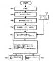
図4Aを参照すると、ブロック160ではシステム100を初期化し、患者の経歴情報の入力を可能にし、マーカ120aから120c及びプローブ125がカメラアレイ106の視野体積(viewing volume)の範囲内にあるかどうかを試験する。ブロック164では幾何学的なパラメータを決定するためにマーカのそれぞれから入力を受け取り、ブロック168では視野体積の範囲内での関節124の周りでの肢の移動に続き、または間にマーカ120aから120cをデジタル化することによって運動の範囲を計算する。肢が運動の最大範囲を通して動かされる間、肢の場所は公知の方法で多様な場所で繰り返しデジタル化される。外科医は、通常、最大屈曲、最大伸張、最大内部回転、最大外部回転、最大外転、及び最大内転等の極端な位置を評価する。また、外科医は、通常、これらのそれぞれの適度な位置をデジタル化する。幾何学的なパラメータ及び運動範囲データを備える第一の運動学データで、関節の運動学を評価し、最適な関節窩位置を求めるには十分であり、事実上さらに優れた結果を生じさせるため、外科医は、提靭帯271、左右ASIS273及び(図3に見られる)恥骨結節275に基づいて解剖学上の骨盤前額面250等の前額面をデジタル化する必要はない。本発明のシステム及び方法で使用される機能上の前額面は、重力を基準にして、例えば起立または着席等の特定の姿勢での骨盤位置を複製する。その結果、これらの機能上の前額面は、静的なシナリオにおけるインプラント位置決めにとっての患者に特定の基準になる。これらは任意に定義された解剖学上の前額面よりも日々の活動の達成にさらに有意義である。ブロック172では、前述されたように力データの無線による受信を介して関節124の軟組織張力パラメータを決定する。ブロック176ではインプラントデータベース143にアクセスし、幾何学的なパラメータ、軟組織張力データ、第一の目標と第二の目標、及び第三の目標から第七の目標の内の一つまたは複数に基づいて最善のインプラントを選ぶ最適化アルゴリズムを実行することによって機能上の目標を計算する。ブロック180では、最適な関節窩位置と最適なインプラント(複数の場合がある)を表示する。ブロック184では、外科医は、トライアルインプラントであるのか、あるいは最終的なインプラントであるのかに関わりなく、インプラント受け入れのために関節124を準備する。関節124を広げること/準備は当該技術で公知であるように、適切なアクティブなまたはパッシブな追跡調査マーカをその上に有する適切なリーマ(不図示であるが、周知)を誘導することによって等、システム100によって誘導できるであろう。最後に、ブロック188では、インプラント(複数の場合がある)が関節124の中に取り付けられる。ブロック184と188の間では、ブロック172が、関節窩の位置決め及びインプラントの選択を微調整するために前述されたようにスマートトライアルの実行とともにおそらく繰り返すことができるであろうことに留意する必要がある。ブロック168、172は結合できる、または図示されているように別々であるかのどちらかである。 Referring to FIG. 4A, at
図4Bを参照すると、ブロック180に類似するまたは同一のブロック181は、ブロック160、164、168、172及び143から取得されたデータを最適化することによって第一の関節窩位置及び第一のインプラントを求める。ブロック190は、傾斜と前傾のさまざまな値を基準にして第一の関節窩位置/第一のインプラントの機能上の属性を表示する。例えば、ブロック190は、多様な曲線138aから138fを基準にして点137(図5)を表示できるであろう。最後に、ブロック192、194では、最適関節窩位置及び最適インプラントがそれぞれ選択される。前述されたスマートトライアルは、必要であれば、追加の最適化データを取得するためにブロック190とブロック192、194の間で実行できるであろう。 Referring to FIG. 4B, a
図6を参照すると、リーミングツール200のナビゲーションが、ディスプレイ104(図1も参照すること)上に適切なしるしを付けることによって達成されてよい。例えば、所望されるリーミング場所を反映する1本または複数本のガイドライン204aから204dがディスプレイ104に表示される。リーミングツール200の位置は、枠(crucible)207等の適切なしるしによってリアルタイムで表示され、該枠207はガイドライン186を基準にして表示される。該しるしは、最大リーミング深度を反映するガイドライン208をさらに含むことができるであろう。外科医が、リーミングの前に外科医の推定位置を試験するために仮想インプラントの多様な仮想上の位置について(同一出願人による米国出願、出願番号第10/655,922号に説明されるように)一回または複数回の仮想トライアルを実行してよいことに留意する必要がある。システム100は、外科医の推定される最適関節窩位置を評価するためにこのような仮想トライアル(複数の場合がある)の予想される運動学的結果を表示するであろう。外科医は、さまざまな寸法を有するさまざまな仮想インプラントを活用して追加の仮想トライアルを実行してもよい。試行錯誤のプロセスを通して、外科医は最適な関節窩位置を求め、いったん最適な関節窩位置が決定されると、システムは関節の準備を誘導するためにガイドライン204aから204b(図6)等の適切なしるしを表示する。 Referring to FIG. 6, navigation of the
図7を参照すると、外科医は、必要であれば、前述されたブロック160,164、168及び172と関連して説明されるデータ収集の間に患者の解剖学上の平面を基準にして、重力平面つまり鉛直線平面Pを確立し、追跡調査してよい。股関節の処置では、鉛直線平面Pによってシステムは重力を基準にして骨盤の位置を評価できる。この関連で、最適関節窩位置決めは、一般的には、患者が横たわっているときに骨盤の機能上の前額面が鉛直線平面Pを基準にして偏位する、中立的な立場で、骨盤で評価される。偏位の角度は性別の間だけではなく、ライフスタイル、年齢、人種等に応じても変化する。それは通常−10度から+10度の範囲であるが、この範囲外である場合もある。遠直線平面Pを追跡調査することにより、システムは、骨盤に対して重力の影響を行使する水平ではない骨盤によって引き起こされる不正確さによってデータを分かりにくくしたり、処置中に患者の骨盤のシフトによりデータを分かりにくくすることなく、鉛直線平面Pを基準にして、あるいは好ましくは確立された機能上の前額面を基準にして関節の準備またはインプラントナビゲーションを誘導できる。 Referring to FIG. 7, the surgeon may, if necessary, determine the gravity relative to the patient's anatomical plane during the data collection described in connection with the previously described
鉛直線平面Pを手術中に確立する容易な方法は、手術台235を平らにするために一つまたは複数の適切な水平器230を使用する。台235は、システムが台235の位置と向きを追跡調査できるために、一つまたは複数の適切な追跡調査マーカ240を含む。台235は第一の高さ位置Aから第二の高さ位置Bに移動し、鉛直線平面Pを確立するために、台の位置はこれらの位置AとBのそれぞれでデジタル化される。前述されたように、以前に確立された機能上の前額面は、ここで鉛直線平面を基準にして追跡調査できる。その結果、この平面の位置と向きは、図8Aから図8Cに描かれているように鉛直線平面Pを基準にして評価されてよい。 An easy way to establish a vertical plane P during surgery uses one or more
肩の場合、基準位置は中立的な姿勢である。これは術後の柔軟性及び安定性を最大限にするために肩の適切な位置決めを基準にして情報を提供する。 In the case of the shoulder, the reference position is a neutral posture. This provides information relative to proper positioning of the shoulders to maximize post-operative flexibility and stability.
手術ナビゲーションシステム100は、開示された機能を実行するために適切なソフトウェア及び回路網を含む。システムのコンピュータプログラムは、本書に開示されている多様な特徴を実行するためにあらゆる適切なユーザインタフェース画面を含んでよい。
本発明の多数の変型は前記説明を鑑みて当業者に明らかになるであろう。例えば、仮想トライアルは、関節からの肢の変位の前または後等の、関節形成処置の間のいかなる時点において実行されてもよい。したがって、本説明は本書に教示される発明概念を単に例示すると解釈されるべきであり、当業者が本発明を作り、使用し、これを実施するための最良の形態を教示できるために提示されている。添付請求項の範囲内になるすべての変型に対する独占権が留保される。 Many variations of the invention will become apparent to those skilled in the art in view of the foregoing description. For example, a virtual trial may be performed at any point during the arthroplasty procedure, such as before or after displacement of the limb from the joint. Accordingly, this description is to be construed as illustrative only of the inventive concepts taught herein and is presented to enable one skilled in the art to teach the best mode of making, using, and implementing the invention. ing. Exclusive rights are reserved for all variations that fall within the scope of the appended claims.
(関連出願の相互参照)
該当なし。(Cross-reference of related applications)
Not applicable.
(連邦による資金提供を受けた研究または開発に関する参照)
該当なし。(Reference for federally funded research or development)
Not applicable.
(連続リスト)
該当なし。(Continuous list)
Not applicable.
Claims (23)
Translated fromJapanese関節窩領域及び肢の幹状部の態様をデジタル化することを含む、該関節と該関節に属する肢の幾何学的なパラメータを提供するために目印をデジタル化するステップと、
運動範囲パラメータを決定するステップと、
軟組織張力パラメータを決定するステップと、
目印データ、該運動範囲パラメータ、該軟組織張力パラメータ、及び潜在的なインプラントのデータベースに基づいて機能上の目標を計算するステップと、
該関節窩の識別された回転の中心に基づいて安定性制約を考慮に入れて衝撃を最小限に抑えるために最適な関節窩向きを求めるステップと、
該機能上の目標に適合させるためにインプラント構成要素組み合わせを選び位置決めを行うステップと、
識別された幹状部位置及び該関節窩の該識別された回転の中心に基づいて安定性の制約を考慮に入れて衝撃を最小限に抑えるために最適な関節窩位置を求めるステップと、
該最適の関節窩位置に基づいて該機能上の目標に適合させるために最適な構成要素組み合わせを選び位置決めを行うステップと、
該最適の関節窩位置及び該識別された幹状部位置に基づいて該機能上の目標に適合させるために、最適な構成要素組み合わせ及び向きを求めるステップと、
該機能上の目標に適合させるために最終的な構成要素の組み合わせ及び該構成要素の最終的な向きを選ぶステップと、
該最終的なインプラント構成要素を受け入れるために該関節を準備するステップと、
該関節に該最終的なインプラント構成要素を取り付けるステップと、
を備える方法。A method for performing articulation of a ball joint using a surgical navigation system comprising:
Digitizing the landmarks to provide geometric parameters of the joint and the limb belonging to the joint, including digitizing aspects of the glenoid region and the limb stem;
Determining a range of motion parameter;
Determining a soft tissue tension parameter;
Calculating functional goals based on landmark data, the range of motion parameters, the soft tissue tension parameters, and a database of potential implants;
Determining an optimal glenoid orientation to take into account stability constraints and minimize impact based on the identified center of rotation of the glenoid;
Selecting and positioning implant component combinations to meet the functional goals;
Determining an optimal glenoid position to take into account stability constraints and minimize impact based on the identified stem position and the identified center of rotation of the glenoid;
Selecting and positioning an optimal combination of components to meet the functional goal based on the optimal glenoid position;
Determining an optimal component combination and orientation to meet the functional goal based on the optimal glenoid location and the identified stem location;
Selecting the final combination of components and the final orientation of the components to meet the functional goals;
Preparing the joint to receive the final implant component;
Attaching the final implant component to the joint;
A method comprising:
結果として生じる関節形状の解剖学上の値、運動学的な値、及び張力値に対する該幾何学的なパラメータの影響を表現する複数の曲線が該グラフ上に表示される、
請求項1に記載の方法。A graph having an axis indicating the positioning or sizing parameters of the optimal component combination is displayed;
A plurality of curves representing the effect of the geometric parameter on the resulting anatomical, kinematic, and tension values of the joint shape are displayed on the graph;
The method of claim 1.
該第一の軸が前傾の量であり、第二の軸が該関節窩の傾斜の量であり、
結果的に生じる関節形状の解剖学上の値、運動学的な値、及び張力値に対する、該前傾及び傾斜の影響を示す複数の曲線が該グラフ上に表示される、
請求項2に記載の方法。The graph is displayed with a first axis and a second axis;
The first axis is the amount of anteversion and the second axis is the amount of inclination of the glenoid;
A plurality of curves are displayed on the graph showing the effect of the anteversion and tilt on the resulting anatomical, kinematic, and tension values of the joint shape;
The method of claim 2.
該第一の軸が該幹状部の前傾の量であり、第二の軸がネック角と関節窩偏位の量であり、
結果的に生じる関節形状の解剖学上の値、運動学的な値、及び張力値に対する後者の幾何学的なパラメータの影響を示す複数の曲線が該グラフに表示されている、
請求項2に記載の方法。The graph is displayed with a first axis and a second axis;
The first axis is the amount of anteversion of the stem, the second axis is the amount of neck angle and glenoid deflection,
A plurality of curves are displayed in the graph showing the effect of the latter geometric parameter on the resulting anatomical, kinematic, and tension values of the joint shape;
The method of claim 2.
幾何学的なパラメータ及び運動範囲データをデジタル化するステップと、
軟組織張力パラメータを測定するステップと、
適切な安定性及び衝撃の最小可能性を提供する第一の関節窩位置を選択するステップと、
肢の長さ、遠位/近位偏位、及び外側/内側偏位に関して該第一の関節窩位置から許容できる公差範囲を確立するステップと、
構成要素の初期インプラント組み合わせを選択するステップと、
該構成要素の初期インプラント組み合わせの属性、及び該構成要素の初期インプラント組み合わせの位置を、構成要素の追加の潜在的なインプラント組み合わせのため、及び該構成要素の初期組み合わせの追加の位置について追加の潜在的な属性の範囲を基準にして計算し、グラフ表示するステップと、
該許容範囲内に留まる一方で、該関節の最適な機能上の特性のために、構成要素の最終的なインプラント組み合わせ及び構成要素の該最終的な組み合わせの最終的な位置に到達するために、構成要素の該初期のインプラント組み合わせと、構成要素の該初期の組み合わせの該初期の位置を修正するステップと、
を含む方法。A method of selecting an implant using a surgical navigation system and placing it in a ball joint by taking into account both geometric and soft tissue tension parameters, comprising:
Digitizing geometric parameters and range of motion data;
Measuring a soft tissue tension parameter;
Selecting a first glenoid position that provides adequate stability and minimal likelihood of impact;
Establishing an acceptable tolerance range from the first glenoid position for limb length, distal / proximal deviation, and lateral / medial deviation;
Selecting an initial implant combination of components;
Attributes of the initial implant combination of the component, and the position of the initial implant combination of the component, additional potential for additional potential implant combinations of the component and for additional positions of the initial combination of components Calculating and graphing based on a range of typical attributes,
To reach the final implant combination of the component and the final position of the final combination of components for optimal functional characteristics of the joint while remaining within the tolerance range Modifying the initial implant combination of components and the initial position of the initial combination of components;
Including methods.
結果として生じる関節形状の解剖学上の値、運動学的な値、及び張力値に対する該幾何学的なパラメータの影響を表わす複数の曲線が該グラフに表示されている、
請求項8に記載の方法。A graph is displayed having an axis indicating the geometric parameters of the implant combination of components;
A plurality of curves representing the effect of the geometric parameter on the resulting anatomical, kinematic and tension values of the joint shape are displayed in the graph;
The method of claim 8.
結果として生じる関節形状の解剖学上の値、運動学的な値、及び張力値に対する該関節窩の該前傾及び傾斜の影響を示す複数の曲線が該グラフ上に表示されている、
請求項12に記載の方法。The first axis is the amount of anteversion and the second axis is the amount of inclination of the glenoid;
A plurality of curves are displayed on the graph showing the effect of the anteversion and inclination of the glenoid on the resulting anatomical, kinematic, and tension values of the joint shape;
The method of claim 12.
結果として生じる関節形状の解剖学上の値、運動学的な値及び張力値に対する、該幹状部の該前傾、及びネック角及び関節窩偏位の量の影響を示す複数の曲線が該グラフに表示されている、
請求項12に記載の方法。The first axis is the amount of anteversion of the stem, the second axis is the amount of neck angle and glenoid deflection,
A plurality of curves showing the effect of the amount of anteversion of the stem and neck angle and glenoid displacement on the resulting anatomical, kinematic and tension values of the joint shape Displayed in the graph,
The method of claim 12.
所定の休止位置を基準にして該関節の機能上の平面を確立し、追跡調査するステップと、
該機能上の平面を基準にして鉛直線平面を確立し、追跡調査するステップと、
インプラント構成要素を受け入れるために該関節を準備するステップと、
衝撃を最小限に抑え、運動範囲を最大限にするインプラント構成要素を選ぶステップと、
該準備された関節の中に該選ばれたインプラント構成要素を差し込むステップと、
を含む方法。A method of performing joint arthroplasty using a surgical navigation system,
Establishing and tracking a functional plane of the joint with respect to a predetermined rest position;
Establishing and tracking a vertical plane with respect to the functional plane; and
Preparing the joint to receive an implant component;
Choosing implant components that minimize impact and maximize range of motion;
Inserting the selected implant component into the prepared joint;
Including methods.
該準備された関節の中にトライアル構成要素を差し込むステップと、
所定の目標を基準にして該トライアル構成要素を評価するステップと、
をさらに含む請求項18に記載の方法。The method is
Inserting a trial component into the prepared joint;
Evaluating the trial component with respect to a predetermined goal;
The method of claim 18 further comprising:
Applications Claiming Priority (3)
| Application Number | Priority Date | Filing Date | Title |
|---|---|---|---|
| US10/961,455US8007448B2 (en) | 2004-10-08 | 2004-10-08 | System and method for performing arthroplasty of a joint and tracking a plumb line plane |
| US10/961,455 | 2004-10-08 | ||
| PCT/IB2005/004073WO2006067634A1 (en) | 2004-10-08 | 2005-10-07 | System and method for performing arthroplasty of a joint and tracking a plumb line plane |
Publications (2)
| Publication Number | Publication Date |
|---|---|
| JP2008515512Atrue JP2008515512A (en) | 2008-05-15 |
| JP5132313B2 JP5132313B2 (en) | 2013-01-30 |
Family
ID=36263046
Family Applications (1)
| Application Number | Title | Priority Date | Filing Date |
|---|---|---|---|
| JP2007535275AExpired - LifetimeJP5132313B2 (en) | 2004-10-08 | 2005-10-07 | Method for controlling a surgical navigation system |
Country Status (4)
| Country | Link |
|---|---|
| US (1) | US8007448B2 (en) |
| JP (1) | JP5132313B2 (en) |
| DE (1) | DE112005002453B4 (en) |
| WO (1) | WO2006067634A1 (en) |
Cited By (5)
| Publication number | Priority date | Publication date | Assignee | Title |
|---|---|---|---|---|
| JP2013521032A (en)* | 2010-03-04 | 2013-06-10 | シーメンス アクティエンゲゼルシャフト | Medical examination and / or treatment equipment |
| JP2021151490A (en)* | 2014-02-25 | 2021-09-30 | デピュイ・シンセス・プロダクツ・インコーポレイテッド | System and method for in-surgery image analysis |
| US11642174B2 (en) | 2014-02-25 | 2023-05-09 | DePuy Synthes Products, Inc. | Systems and methods for intra-operative image analysis |
| US11887306B2 (en) | 2021-08-11 | 2024-01-30 | DePuy Synthes Products, Inc. | System and method for intraoperatively determining image alignment |
| US12295772B2 (en) | 2014-02-25 | 2025-05-13 | DePuy Synthes Products, Inc. | Systems and methods for intra-operative image analysis |
Families Citing this family (101)
| Publication number | Priority date | Publication date | Assignee | Title |
|---|---|---|---|---|
| FR2816200A1 (en) | 2000-11-06 | 2002-05-10 | Praxim | DETERMINING THE POSITION OF A KNEE PROSTHESIS |
| WO2004014219A2 (en)* | 2002-08-09 | 2004-02-19 | Kinamed, Inc. | Non-imaging tracking tools and method for hip replacement surgery |
| EA008902B1 (en)* | 2003-11-12 | 2007-08-31 | Интернэшнл Пэйтент Оунерз (Кайман) Лимитед | A gauge for use in a surgical procedure |
| US7458989B2 (en)* | 2005-06-30 | 2008-12-02 | University Of Florida Rearch Foundation, Inc. | Intraoperative joint force measuring device, system and method |
| US20070179626A1 (en)* | 2005-11-30 | 2007-08-02 | De La Barrera Jose L M | Functional joint arthroplasty method |
| US9808262B2 (en) | 2006-02-15 | 2017-11-07 | Howmedica Osteonics Corporation | Arthroplasty devices and related methods |
| CA2642615A1 (en) | 2006-02-15 | 2007-08-30 | Otismed Corp | Arthroplasty jigs and related methods |
| US8337426B2 (en)* | 2009-03-24 | 2012-12-25 | Biomet Manufacturing Corp. | Method and apparatus for aligning and securing an implant relative to a patient |
| US9289253B2 (en) | 2006-02-27 | 2016-03-22 | Biomet Manufacturing, Llc | Patient-specific shoulder guide |
| US9907659B2 (en) | 2007-04-17 | 2018-03-06 | Biomet Manufacturing, Llc | Method and apparatus for manufacturing an implant |
| US8167823B2 (en)* | 2009-03-24 | 2012-05-01 | Biomet Manufacturing Corp. | Method and apparatus for aligning and securing an implant relative to a patient |
| US9339278B2 (en) | 2006-02-27 | 2016-05-17 | Biomet Manufacturing, Llc | Patient-specific acetabular guides and associated instruments |
| US9173661B2 (en) | 2006-02-27 | 2015-11-03 | Biomet Manufacturing, Llc | Patient specific alignment guide with cutting surface and laser indicator |
| US8603180B2 (en) | 2006-02-27 | 2013-12-10 | Biomet Manufacturing, Llc | Patient-specific acetabular alignment guides |
| US9345548B2 (en) | 2006-02-27 | 2016-05-24 | Biomet Manufacturing, Llc | Patient-specific pre-operative planning |
| US8591516B2 (en) | 2006-02-27 | 2013-11-26 | Biomet Manufacturing, Llc | Patient-specific orthopedic instruments |
| US8407067B2 (en) | 2007-04-17 | 2013-03-26 | Biomet Manufacturing Corp. | Method and apparatus for manufacturing an implant |
| US9918740B2 (en) | 2006-02-27 | 2018-03-20 | Biomet Manufacturing, Llc | Backup surgical instrument system and method |
| US20150335438A1 (en) | 2006-02-27 | 2015-11-26 | Biomet Manufacturing, Llc. | Patient-specific augments |
| US7699793B2 (en)* | 2006-03-07 | 2010-04-20 | Brainlab Ag | Method and device for detecting and localising an impingement of joint components |
| JP2009529954A (en)* | 2006-03-14 | 2009-08-27 | マコ サージカル コーポレーション | Prosthetic device and system and method for implanting a prosthetic device |
| US9795399B2 (en) | 2006-06-09 | 2017-10-24 | Biomet Manufacturing, Llc | Patient-specific knee alignment guide and associated method |
| EP2032087A1 (en)* | 2006-06-19 | 2009-03-11 | IGO Technologies Inc. | Joint placement methods and apparatuses |
| EP1882457B1 (en)* | 2006-07-25 | 2012-03-28 | BrainLAB AG | Method and device for representing the orientation of an object to ball joints |
| US8214016B2 (en) | 2006-12-12 | 2012-07-03 | Perception Raisonnement Action En Medecine | System and method for determining an optimal type and position of an implant |
| US8460302B2 (en) | 2006-12-18 | 2013-06-11 | Otismed Corporation | Arthroplasty devices and related methods |
| US8784425B2 (en) | 2007-02-28 | 2014-07-22 | Smith & Nephew, Inc. | Systems and methods for identifying landmarks on orthopedic implants |
| US8814868B2 (en)* | 2007-02-28 | 2014-08-26 | Smith & Nephew, Inc. | Instrumented orthopaedic implant for identifying a landmark |
| US20100153081A1 (en) | 2008-12-11 | 2010-06-17 | Mako Surgical Corp. | Implant planning for multiple implant components using constraints |
| EP2136715B1 (en)* | 2007-04-19 | 2014-06-25 | Mako Surgical Corp. | Implant planning using captured joint motion information |
| US9044345B2 (en)* | 2007-05-22 | 2015-06-02 | Brainlab Ag | Navigated placement of pelvic implant based on combined anteversion by applying Ranawat's sign or via arithmetic formula |
| EP2200530A2 (en)* | 2007-09-12 | 2010-06-30 | Nobel Biocare Services AG | Method and system for planning a medical procedure and generating data related to said medical procedure |
| DE102007049668B3 (en)* | 2007-10-17 | 2009-04-16 | Aesculap Ag | Method and device for determining the angular position of an acetabular cup in a pelvic bone |
| DE102007049671A1 (en)* | 2007-10-17 | 2009-04-30 | Aesculap Ag | Method and device for determining the frontal plane of the pelvic bone |
| USD642263S1 (en) | 2007-10-25 | 2011-07-26 | Otismed Corporation | Arthroplasty jig blank |
| US8460303B2 (en) | 2007-10-25 | 2013-06-11 | Otismed Corporation | Arthroplasty systems and devices, and related methods |
| US20090125117A1 (en)* | 2007-11-14 | 2009-05-14 | Francois Paradis | Leg alignment and length measurement in hip replacement surgery |
| US10582934B2 (en) | 2007-11-27 | 2020-03-10 | Howmedica Osteonics Corporation | Generating MRI images usable for the creation of 3D bone models employed to make customized arthroplasty jigs |
| US8737700B2 (en) | 2007-12-18 | 2014-05-27 | Otismed Corporation | Preoperatively planning an arthroplasty procedure and generating a corresponding patient specific arthroplasty resection guide |
| US8221430B2 (en) | 2007-12-18 | 2012-07-17 | Otismed Corporation | System and method for manufacturing arthroplasty jigs |
| US8715291B2 (en) | 2007-12-18 | 2014-05-06 | Otismed Corporation | Arthroplasty system and related methods |
| US8777875B2 (en) | 2008-07-23 | 2014-07-15 | Otismed Corporation | System and method for manufacturing arthroplasty jigs having improved mating accuracy |
| US8617171B2 (en) | 2007-12-18 | 2013-12-31 | Otismed Corporation | Preoperatively planning an arthroplasty procedure and generating a corresponding patient specific arthroplasty resection guide |
| US8311306B2 (en) | 2008-04-30 | 2012-11-13 | Otismed Corporation | System and method for image segmentation in generating computer models of a joint to undergo arthroplasty |
| US8160345B2 (en) | 2008-04-30 | 2012-04-17 | Otismed Corporation | System and method for image segmentation in generating computer models of a joint to undergo arthroplasty |
| US8480679B2 (en) | 2008-04-29 | 2013-07-09 | Otismed Corporation | Generation of a computerized bone model representative of a pre-degenerated state and useable in the design and manufacture of arthroplasty devices |
| US8545509B2 (en) | 2007-12-18 | 2013-10-01 | Otismed Corporation | Arthroplasty system and related methods |
| US9220514B2 (en) | 2008-02-28 | 2015-12-29 | Smith & Nephew, Inc. | System and method for identifying a landmark |
| US8734455B2 (en) | 2008-02-29 | 2014-05-27 | Otismed Corporation | Hip resurfacing surgical guide tool |
| FR2932677B1 (en)* | 2008-06-20 | 2010-06-25 | Univ Bretagne Occidentale | SYSTEM FOR ASSISTING THE IMPLANTATION OF A HIP PROSTHESIS ON AN INDIVIDUAL. |
| FR2932674B1 (en) | 2008-06-20 | 2011-11-18 | Tornier Sa | METHOD FOR MODELING A GLENOIDAL SURFACE OF AN OMOPLATE, DEVICE FOR IMPLANTING A GLENOIDAL COMPONENT OF A SHOULDER PROSTHESIS, AND METHOD FOR MANUFACTURING SUCH COMPOUND |
| US8617175B2 (en) | 2008-12-16 | 2013-12-31 | Otismed Corporation | Unicompartmental customized arthroplasty cutting jigs and methods of making the same |
| US8078440B2 (en) | 2008-09-19 | 2011-12-13 | Smith & Nephew, Inc. | Operatively tuning implants for increased performance |
| US8588892B2 (en) | 2008-12-02 | 2013-11-19 | Avenir Medical Inc. | Method and system for aligning a prosthesis during surgery using active sensors |
| US20100250276A1 (en)* | 2009-03-26 | 2010-09-30 | Jay Pierce | System and method for an orthopedic dynamic data repository and registry for clinical |
| US8945147B2 (en) | 2009-04-27 | 2015-02-03 | Smith & Nephew, Inc. | System and method for identifying a landmark |
| US9031637B2 (en) | 2009-04-27 | 2015-05-12 | Smith & Nephew, Inc. | Targeting an orthopaedic implant landmark |
| US9358130B2 (en)* | 2012-03-29 | 2016-06-07 | DePuy Synthes Products, Inc. | Surgical instrument and method of positioning an acetabular prosthetic component |
| RU2012157125A (en) | 2010-06-03 | 2014-07-20 | Смит Энд Нефью, Инк. | ORTHOPEDIC IMPLANT |
| JP2014504161A (en) | 2010-09-01 | 2014-02-20 | メイヨ フォンデーシヨン フォー メディカル エジュケーション アンド リサーチ | Method for optimizing arthroplasty component design |
| US9320608B2 (en) | 2010-09-01 | 2016-04-26 | Mayo Foundation For Medical Education And Research | Method for optimization of joint arthroplasty component design |
| US9968376B2 (en) | 2010-11-29 | 2018-05-15 | Biomet Manufacturing, Llc | Patient-specific orthopedic instruments |
| KR20130129246A (en) | 2010-12-17 | 2013-11-27 | 아브니르 메디컬 아이엔씨. | Method and system for aligning a prosthesis during surgery |
| WO2012103169A2 (en) | 2011-01-25 | 2012-08-02 | Smith & Nephew, Inc. | Targeting operation sites |
| EP2672916A4 (en)* | 2011-02-08 | 2015-01-14 | Gen Hospital Corp | SYSTEMS AND METHODS FOR PATIENT POSITIONING |
| RU2013153116A (en) | 2011-05-06 | 2015-06-20 | Смит Энд Нефью, Инк. | TARGETING FOR SIGNIFICANT POINTS OF ORTHOPEDIC DEVICES |
| WO2012173890A2 (en) | 2011-06-16 | 2012-12-20 | Smith & Nephew, Inc. | Surgical alignment using references |
| EP2775966B1 (en) | 2011-10-24 | 2015-09-16 | Synvasive Technology, Inc. | Knee balancing systems |
| EP2819610B1 (en) | 2012-02-29 | 2023-04-12 | Smith & Nephew, Inc. | Determining anatomical orientations |
| US9314188B2 (en) | 2012-04-12 | 2016-04-19 | Intellijoint Surgical Inc. | Computer-assisted joint replacement surgery and navigation systems |
| CN102688097B (en)* | 2012-05-14 | 2014-11-26 | 清华大学 | Attitude acquisition method and system for acetabulum and femoral head in artificial hip joint replacement |
| US20140031829A1 (en)* | 2012-07-30 | 2014-01-30 | Orthosoft, Inc. | Method and system for creating frame of reference for cas with inertial sensors |
| US9402637B2 (en) | 2012-10-11 | 2016-08-02 | Howmedica Osteonics Corporation | Customized arthroplasty cutting guides and surgical methods using the same |
| SE536759C2 (en) | 2012-10-18 | 2014-07-15 | Ortoma Ab | Method and system for planning position for implant component |
| US9308102B2 (en) | 2013-03-04 | 2016-04-12 | Howmedica Osteonics Corp. | Acetabular cup positioning device |
| US9585768B2 (en) | 2013-03-15 | 2017-03-07 | DePuy Synthes Products, Inc. | Acetabular cup prosthesis alignment system and method |
| US9247998B2 (en) | 2013-03-15 | 2016-02-02 | Intellijoint Surgical Inc. | System and method for intra-operative leg position measurement |
| ITMI20130405A1 (en) | 2013-03-18 | 2014-09-19 | Medacta Int Sa | INSTRUMENTARY FOR THE INSTALLATION OF AN ACETABULAR PROSTHESIS |
| EP3057524B1 (en) | 2013-10-10 | 2019-11-20 | Imascap | Method for designing and producing a shoulder surgery guide |
| EP3925574A1 (en)* | 2013-11-08 | 2021-12-22 | Imascap | Pre-operatively planned adaptive glenoid implants and method for planning its design |
| US10405993B2 (en) | 2013-11-13 | 2019-09-10 | Tornier Sas | Shoulder patient specific instrument |
| US20150201974A1 (en)* | 2014-01-21 | 2015-07-23 | Warsaw Orthopedic, Inc. | Surgical instrument and method of use |
| CN106535827B (en)* | 2014-06-10 | 2018-04-06 | 梅约医学教育与研究基金会 | Method for optimizing arthroplasty component design |
| AU2015394606C1 (en) | 2015-05-08 | 2018-08-16 | Smith & Nephew Asia Pacific Pte. Limited | Determination of an implant orientation relative to a bone |
| US9913691B2 (en) | 2015-08-12 | 2018-03-13 | The Cleveland Clinic Foundation | System and method for model-based surgical planning |
| EP3389513A1 (en) | 2015-12-16 | 2018-10-24 | Tornier, Inc. | Patient specific instruments and methods for joint prosthesis |
| US11229489B2 (en) | 2016-06-16 | 2022-01-25 | Zimmer, Inc. | Soft tissue balancing in articular surgery |
| US10136952B2 (en) | 2016-06-16 | 2018-11-27 | Zimmer, Inc. | Soft tissue balancing in articular surgery |
| CA3039654A1 (en)* | 2016-10-07 | 2018-04-12 | New York Society For The Relief Of The Ruptured And Crippled, Maintaining The Hospital For Special Surgery | Patient specific 3-d interactive total joint model and surgical planning system |
| US10722310B2 (en) | 2017-03-13 | 2020-07-28 | Zimmer Biomet CMF and Thoracic, LLC | Virtual surgery planning system and method |
| EP3618715A4 (en)* | 2017-06-19 | 2021-02-17 | Mohamed R. Mahfouz | HIP SURGICAL NAVIGATION USING FLUOROSCOPY AND TRACKING SENSORS |
| EP3651664A1 (en) | 2017-07-11 | 2020-05-20 | Tornier, Inc. | Guides and instruments for improving accuracy of glenoid implant placement |
| US10959742B2 (en) | 2017-07-11 | 2021-03-30 | Tornier, Inc. | Patient specific humeral cutting guides |
| CA3087066A1 (en) | 2017-12-29 | 2019-07-04 | Tornier, Inc. | Patient specific humeral implant components |
| CA3178420A1 (en) | 2020-05-15 | 2021-11-18 | John Black | Dynamic registration of anatomy using augmented reality |
| US11107586B1 (en) | 2020-06-24 | 2021-08-31 | Cuptimize, Inc. | System and method for analyzing acetabular cup position |
| US20220130552A1 (en)* | 2020-10-27 | 2022-04-28 | Zimmer, Inc | Knee arthroplasty functional digital twin |
| EP4236851A1 (en) | 2020-10-30 | 2023-09-06 | MAKO Surgical Corp. | Robotic surgical system with slingshot prevention |
| US12193718B2 (en) | 2021-04-09 | 2025-01-14 | Smith & Nephew, Inc. | Orthopedic surgical instrument |
| USD1044829S1 (en) | 2021-07-29 | 2024-10-01 | Mako Surgical Corp. | Display screen or portion thereof with graphical user interface |
| US12324615B2 (en) | 2021-11-05 | 2025-06-10 | Mako Surgical Corp. | Assessment of soft tissue tension in hip procedures |
Citations (5)
| Publication number | Priority date | Publication date | Assignee | Title |
|---|---|---|---|---|
| US5995738A (en)* | 1997-02-21 | 1999-11-30 | Carnegie Mellon University | Apparatus and method for facilitating the implantation of artificial components in joints |
| JP2000507846A (en)* | 1996-02-22 | 2000-06-27 | インテグレイテッド サージカル システムズ,インコーポレイテッド | Computer Aided System for Revised Total Hip Arthroplasty |
| JP2001095826A (en)* | 1999-01-29 | 2001-04-10 | Depuy Orthopaedics Inc | Shoulder prosthesis provided with humeral fracture part stem |
| WO2003041611A2 (en)* | 2001-11-14 | 2003-05-22 | White Michael R | Apparatus and methods for making intraoperative orthopedic measurements |
| WO2003079940A2 (en)* | 2002-03-19 | 2003-10-02 | The Board Of Trustees Of The University Of Illinois | System and method for prosthetic fitting and balancing in joints |
Family Cites Families (86)
| Publication number | Priority date | Publication date | Assignee | Title |
|---|---|---|---|---|
| US4323459A (en)* | 1978-08-09 | 1982-04-06 | Petrolite Corporation | Process of inhibiting scale formation in aqueous systems using quaternary ammonium salts of α-1,4-thiazine alkanephosphonic acids |
| US4396945A (en)* | 1981-08-19 | 1983-08-02 | Solid Photography Inc. | Method of sensing the position and orientation of elements in space |
| US4722056A (en)* | 1986-02-18 | 1988-01-26 | Trustees Of Dartmouth College | Reference display systems for superimposing a tomagraphic image onto the focal plane of an operating microscope |
| DE3717871C3 (en)* | 1987-05-27 | 1995-05-04 | Georg Prof Dr Schloendorff | Method and device for reproducible visual representation of a surgical intervention |
| JPH02503519A (en)* | 1987-05-27 | 1990-10-25 | サージカル ナビゲーション テクノロジース インコーポレーティッド(アン アフィリエイティッド カンパニー オブ ソファマー ダンネク グループ インコーポレーティッド) | Method and apparatus for reproducibly optically displaying surgical procedures |
| JPS6472736A (en)* | 1987-09-14 | 1989-03-17 | Toshiba Corp | Mri apparatus |
| US4991579A (en)* | 1987-11-10 | 1991-02-12 | Allen George S | Method and apparatus for providing related images over time of a portion of the anatomy using fiducial implants |
| EP0326768A3 (en) | 1988-02-01 | 1991-01-23 | Faro Medical Technologies Inc. | Computer-aided surgery apparatus |
| US4951653A (en)* | 1988-03-02 | 1990-08-28 | Laboratory Equipment, Corp. | Ultrasound brain lesioning system |
| US4869247A (en)* | 1988-03-11 | 1989-09-26 | The University Of Virginia Alumni Patents Foundation | Video tumor fighting system |
| US4979949A (en)* | 1988-04-26 | 1990-12-25 | The Board Of Regents Of The University Of Washington | Robot-aided system for surgery |
| DE3904595C1 (en) | 1989-02-16 | 1990-04-19 | Deutsches Krebsforschungszentrum Stiftung Des Oeffentlichen Rechts, 6900 Heidelberg, De | Device for determining the spatial coordinates of stereotactic target points by means of X-ray pictures |
| DE69026196T2 (en)* | 1989-11-08 | 1996-09-05 | George S Allen | Mechanical arm for an interactive, image-controlled, surgical system |
| US5222499A (en)* | 1989-11-15 | 1993-06-29 | Allen George S | Method and apparatus for imaging the anatomy |
| US5198877A (en)* | 1990-10-15 | 1993-03-30 | Pixsys, Inc. | Method and apparatus for three-dimensional non-contact shape sensing |
| DE69132412T2 (en)* | 1990-10-19 | 2001-03-01 | St. Louis University, St. Louis | LOCALIZATION SYSTEM FOR A SURGICAL PROBE FOR USE ON THE HEAD |
| US5197488A (en)* | 1991-04-05 | 1993-03-30 | N. K. Biotechnical Engineering Co. | Knee joint load measuring instrument and joint prosthesis |
| US5309001A (en)* | 1991-11-25 | 1994-05-03 | Sharp Kabushiki Kaisha | Light-emitting diode having a surface electrode of a tree-like form |
| DE4207901C3 (en)* | 1992-03-12 | 1999-10-07 | Aesculap Ag & Co Kg | Method and device for displaying a work area in a three-dimensional structure |
| AT399647B (en)* | 1992-07-31 | 1995-06-26 | Truppe Michael | ARRANGEMENT FOR DISPLAYING THE INTERIOR OF BODIES |
| US5665090A (en)* | 1992-09-09 | 1997-09-09 | Dupuy Inc. | Bone cutting apparatus and method |
| US5309101A (en) | 1993-01-08 | 1994-05-03 | General Electric Company | Magnetic resonance imaging in an inhomogeneous magnetic field |
| US5575794A (en)* | 1993-02-12 | 1996-11-19 | Walus; Richard L. | Tool for implanting a fiducial marker |
| US5799099A (en)* | 1993-02-12 | 1998-08-25 | George S. Allen | Automatic technique for localizing externally attached fiducial markers in volume images of the head |
| US5551429A (en)* | 1993-02-12 | 1996-09-03 | Fitzpatrick; J. Michael | Method for relating the data of an image space to physical space |
| EP0700269B1 (en)* | 1993-04-22 | 2002-12-11 | Image Guided Technologies, Inc. | System for locating relative positions of objects |
| DE9422172U1 (en)* | 1993-04-26 | 1998-08-06 | St. Louis University, St. Louis, Mo. | Specify the location of a surgical probe |
| AU679242B2 (en) | 1993-06-21 | 1997-06-26 | Howmedica Osteonics Corp. | Apparatus and method for aligning knee prostheses |
| JP3690802B2 (en) | 1993-06-21 | 2005-08-31 | ハウメディカ・オステオニクス・コーポレイション | A device that detects the functional center of the hip joint during knee arthroplasty |
| EP0649117A3 (en)* | 1993-10-15 | 1996-01-31 | George S Allen | Method for providing medical images. |
| US5394875A (en)* | 1993-10-21 | 1995-03-07 | Lewis; Judith T. | Automatic ultrasonic localization of targets implanted in a portion of the anatomy |
| US5549616A (en)* | 1993-11-02 | 1996-08-27 | Loma Linda University Medical Center | Vacuum-assisted stereotactic fixation system with patient-activated switch |
| JP3267054B2 (en) | 1994-06-13 | 2002-03-18 | トヨタ自動車株式会社 | Power storage device for solar power |
| US5891157A (en)* | 1994-09-30 | 1999-04-06 | Ohio Medical Instrument Company, Inc. | Apparatus for surgical stereotactic procedures |
| US5695501A (en)* | 1994-09-30 | 1997-12-09 | Ohio Medical Instrument Company, Inc. | Apparatus for neurosurgical stereotactic procedures |
| US5617857A (en)* | 1995-06-06 | 1997-04-08 | Image Guided Technologies, Inc. | Imaging system having interactive medical instruments and methods |
| US5752513A (en)* | 1995-06-07 | 1998-05-19 | Biosense, Inc. | Method and apparatus for determining position of object |
| US5638819A (en)* | 1995-08-29 | 1997-06-17 | Manwaring; Kim H. | Method and apparatus for guiding an instrument to a target |
| US5682886A (en)* | 1995-12-26 | 1997-11-04 | Musculographics Inc | Computer-assisted surgical system |
| US5711299A (en)* | 1996-01-26 | 1998-01-27 | Manwaring; Kim H. | Surgical guidance method and system for approaching a target within a body |
| WO1997029710A1 (en)* | 1996-02-15 | 1997-08-21 | Biosense, Inc. | Medical probes with field transducers |
| WO1997040763A1 (en)* | 1996-04-29 | 1997-11-06 | Philips Electronics N.V. | Image guided surgery system |
| US6205411B1 (en)* | 1997-02-21 | 2001-03-20 | Carnegie Mellon University | Computer-assisted surgery planner and intra-operative guidance system |
| DE29704393U1 (en)* | 1997-03-11 | 1997-07-17 | Aesculap Ag, 78532 Tuttlingen | Device for preoperative determination of the position data of endoprosthesis parts |
| US5921992A (en)* | 1997-04-11 | 1999-07-13 | Radionics, Inc. | Method and system for frameless tool calibration |
| US5970499A (en)* | 1997-04-11 | 1999-10-19 | Smith; Kurt R. | Method and apparatus for producing and accessing composite data |
| US5907395A (en)* | 1997-06-06 | 1999-05-25 | Image Guided Technologies, Inc. | Optical fiber probe for position measurement |
| WO1999001078A2 (en)* | 1997-07-03 | 1999-01-14 | Koninklijke Philips Electronics N.V. | Image-guided surgery system |
| US6081336A (en)* | 1997-09-26 | 2000-06-27 | Picker International, Inc. | Microscope calibrator |
| FR2785517B1 (en)* | 1998-11-10 | 2001-03-09 | Univ Joseph Fourier | METHOD AND DEVICE FOR DETERMINING THE CENTER OF A JOINT |
| US6430434B1 (en)* | 1998-12-14 | 2002-08-06 | Integrated Surgical Systems, Inc. | Method for determining the location and orientation of a bone for computer-assisted orthopedic procedures using intraoperatively attached markers |
| US6702821B2 (en)* | 2000-01-14 | 2004-03-09 | The Bonutti 2003 Trust A | Instrumentation for minimally invasive joint replacement and methods for using same |
| US20010034530A1 (en)* | 2000-01-27 | 2001-10-25 | Malackowski Donald W. | Surgery system |
| US6676706B1 (en)* | 2000-04-26 | 2004-01-13 | Zimmer Technology, Inc. | Method and apparatus for performing a minimally invasive total hip arthroplasty |
| EP1197185B1 (en)* | 2000-10-11 | 2004-07-14 | Stryker Leibinger GmbH & Co. KG | Device for determining or tracking the position of a bone |
| FR2816200A1 (en)* | 2000-11-06 | 2002-05-10 | Praxim | DETERMINING THE POSITION OF A KNEE PROSTHESIS |
| DE10062580B4 (en)* | 2000-12-15 | 2006-07-13 | Aesculap Ag & Co. Kg | Method and device for determining the mechanical axis of a femur |
| GB0101990D0 (en)* | 2001-01-25 | 2001-03-14 | Finsbury Dev Ltd | Surgical system |
| US20040102866A1 (en)* | 2001-01-29 | 2004-05-27 | Harris Simon James | Modelling for surgery |
| DE20102202U1 (en) | 2001-02-07 | 2001-08-02 | Aesculap AG & Co. KG, 78532 Tuttlingen | Device for determining the contour of a recess in a piece of material |
| DE60232315D1 (en)* | 2001-02-27 | 2009-06-25 | Smith & Nephew Inc | SURGICAL NAVIGATION SYSTEM FOR PARTIAL KNEE JOINT CONSTRUCTION |
| US6595997B2 (en)* | 2001-02-28 | 2003-07-22 | Howmedica Osteonics Corp. | Methods used in performing femoral and tibial resection in knee surgery |
| US7909831B2 (en)* | 2001-02-28 | 2011-03-22 | Howmedica Osteonics Corp. | Systems used in performing femoral and tibial resection in knee surgery |
| DE10145587B4 (en)* | 2001-09-15 | 2007-04-12 | Aesculap Ag & Co. Kg | Method and device for testing a marking element for displacement |
| US20050119661A1 (en)* | 2001-11-14 | 2005-06-02 | Hodgson Antony J. | Methods and systems for intraoperative measurement of soft tissue constraints in computer aided total joint replacement surgery |
| US20030153978A1 (en)* | 2002-02-08 | 2003-08-14 | Whiteside Biomechanics, Inc. | Apparatus and method of ligament balancing and component fit check in total knee arthroplasty |
| US6711431B2 (en)* | 2002-02-13 | 2004-03-23 | Kinamed, Inc. | Non-imaging, computer assisted navigation system for hip replacement surgery |
| US6695850B2 (en)* | 2002-02-20 | 2004-02-24 | Robert L. Diaz | Minimally invasive total hip replacement |
| US7831292B2 (en)* | 2002-03-06 | 2010-11-09 | Mako Surgical Corp. | Guidance system and method for surgical procedures with improved feedback |
| US7275218B2 (en)* | 2002-03-29 | 2007-09-25 | Depuy Products, Inc. | Method, apparatus, and program for analyzing a prosthetic device |
| WO2003090022A2 (en)* | 2002-04-16 | 2003-10-30 | Noble Philip C | Computer-based training methods for surgical procedures |
| WO2004001569A2 (en)* | 2002-06-21 | 2003-12-31 | Cedara Software Corp. | Computer assisted system and method for minimal invasive hip, uni knee and total knee replacement |
| DE50200938D1 (en)* | 2002-09-24 | 2004-10-07 | Brainlab Ag | Device and method for determining the opening angle of a joint |
| DE50211647D1 (en) | 2002-11-05 | 2008-03-20 | Brainlab Ag | Method and device for registering a femoral implant |
| JP2006505366A (en)* | 2002-11-07 | 2006-02-16 | コンフォーミス・インコーポレイテッド | Method of determining meniscus size and shape and devised treatment |
| US20040106869A1 (en)* | 2002-11-29 | 2004-06-03 | Ron-Tech Medical Ltd. | Ultrasound tracking device, system and method for intrabody guiding procedures |
| US7319897B2 (en)* | 2002-12-02 | 2008-01-15 | Aesculap Ag & Co. Kg | Localization device display method and apparatus |
| US7209776B2 (en)* | 2002-12-03 | 2007-04-24 | Aesculap Ag & Co. Kg | Method of determining the position of the articular point of a joint |
| US7660623B2 (en)* | 2003-01-30 | 2010-02-09 | Medtronic Navigation, Inc. | Six degree of freedom alignment display for medical procedures |
| US7542791B2 (en)* | 2003-01-30 | 2009-06-02 | Medtronic Navigation, Inc. | Method and apparatus for preplanning a surgical procedure |
| US20050065617A1 (en)* | 2003-09-05 | 2005-03-24 | Moctezuma De La Barrera Jose Luis | System and method of performing ball and socket joint arthroscopy |
| WO2005072629A1 (en) | 2004-01-16 | 2005-08-11 | Smith & Nephew, Inc. | Computer-assisted ligament balancing in total knee arthroplasty |
| US7657298B2 (en)* | 2004-03-11 | 2010-02-02 | Stryker Leibinger Gmbh & Co. Kg | System, device, and method for determining a position of an object |
| US7662113B2 (en)* | 2004-11-05 | 2010-02-16 | California Institute Of Technology | Fingertip tracker |
| FR2884408B1 (en)* | 2005-04-13 | 2007-05-25 | Tornier Sas | SURGICAL DEVICE FOR IMPLANTATION OF A PARTIAL OR TOTAL KNEE PROSTHESIS |
| US20070179626A1 (en)* | 2005-11-30 | 2007-08-02 | De La Barrera Jose L M | Functional joint arthroplasty method |
- 2004
- 2004-10-08USUS10/961,455patent/US8007448B2/enactiveActive
- 2005
- 2005-10-07DEDE112005002453.9Tpatent/DE112005002453B4/ennot_activeExpired - Lifetime
- 2005-10-07WOPCT/IB2005/004073patent/WO2006067634A1/enactiveApplication Filing
- 2005-10-07JPJP2007535275Apatent/JP5132313B2/ennot_activeExpired - Lifetime
Patent Citations (5)
| Publication number | Priority date | Publication date | Assignee | Title |
|---|---|---|---|---|
| JP2000507846A (en)* | 1996-02-22 | 2000-06-27 | インテグレイテッド サージカル システムズ,インコーポレイテッド | Computer Aided System for Revised Total Hip Arthroplasty |
| US5995738A (en)* | 1997-02-21 | 1999-11-30 | Carnegie Mellon University | Apparatus and method for facilitating the implantation of artificial components in joints |
| JP2001095826A (en)* | 1999-01-29 | 2001-04-10 | Depuy Orthopaedics Inc | Shoulder prosthesis provided with humeral fracture part stem |
| WO2003041611A2 (en)* | 2001-11-14 | 2003-05-22 | White Michael R | Apparatus and methods for making intraoperative orthopedic measurements |
| WO2003079940A2 (en)* | 2002-03-19 | 2003-10-02 | The Board Of Trustees Of The University Of Illinois | System and method for prosthetic fitting and balancing in joints |
Cited By (7)
| Publication number | Priority date | Publication date | Assignee | Title |
|---|---|---|---|---|
| JP2013521032A (en)* | 2010-03-04 | 2013-06-10 | シーメンス アクティエンゲゼルシャフト | Medical examination and / or treatment equipment |
| JP2021151490A (en)* | 2014-02-25 | 2021-09-30 | デピュイ・シンセス・プロダクツ・インコーポレイテッド | System and method for in-surgery image analysis |
| US11534127B2 (en) | 2014-02-25 | 2022-12-27 | DePuy Synthes Products, Inc. | Systems and methods for intra-operative image analysis |
| JP7203148B2 (en) | 2014-02-25 | 2023-01-12 | デピュイ・シンセス・プロダクツ・インコーポレイテッド | Systems and methods for intraoperative image analysis |
| US11642174B2 (en) | 2014-02-25 | 2023-05-09 | DePuy Synthes Products, Inc. | Systems and methods for intra-operative image analysis |
| US12295772B2 (en) | 2014-02-25 | 2025-05-13 | DePuy Synthes Products, Inc. | Systems and methods for intra-operative image analysis |
| US11887306B2 (en) | 2021-08-11 | 2024-01-30 | DePuy Synthes Products, Inc. | System and method for intraoperatively determining image alignment |
Also Published As
| Publication number | Publication date |
|---|---|
| DE112005002453T5 (en) | 2007-08-30 |
| WO2006067634A1 (en) | 2006-06-29 |
| JP5132313B2 (en) | 2013-01-30 |
| US8007448B2 (en) | 2011-08-30 |
| US20060095047A1 (en) | 2006-05-04 |
| DE112005002453B4 (en) | 2017-03-16 |
Similar Documents
| Publication | Publication Date | Title |
|---|---|---|
| JP5132313B2 (en) | Method for controlling a surgical navigation system | |
| US12343088B2 (en) | Lower extremities leg length calculation method | |
| US11311339B2 (en) | Computer-assisted hip replacement surgery | |
| CN113993445B (en) | System and method for surgical registration | |
| JP4981257B2 (en) | Surgical device for total hip prosthesis implantation | |
| US9554863B2 (en) | Hip replacement in computer-assisted surgery | |
| EP1893138B1 (en) | Acetabular cup positioning | |
| AU2004290594B2 (en) | Surgical technique and instrumentation for minimal incision hip arthroplasty surgery | |
| JP4621774B2 (en) | Leg alignment for surgical parameter measurement in hip replacement | |
| KR20180103903A (en) | Calibration of the inertial measurement unit (IMU CALIBRATION) | |
| JP2004529699A (en) | Computer assisted insertion of a hip prosthesis | |
| CN103153240A (en) | Patient-matched acetabular alignment tool | |
| US11602399B2 (en) | Systems and methods to adjust bone cut positioning based on bone hardness | |
| AU2011244995B2 (en) | Surgical technique and instrumentation for minimal incision hip arthroplasty surgery |
Legal Events
| Date | Code | Title | Description |
|---|---|---|---|
| A621 | Written request for application examination | Free format text:JAPANESE INTERMEDIATE CODE: A621 Effective date:20080826 | |
| A977 | Report on retrieval | Free format text:JAPANESE INTERMEDIATE CODE: A971007 Effective date:20110527 | |
| A131 | Notification of reasons for refusal | Free format text:JAPANESE INTERMEDIATE CODE: A131 Effective date:20110607 | |
| A521 | Request for written amendment filed | Free format text:JAPANESE INTERMEDIATE CODE: A523 Effective date:20110826 | |
| A131 | Notification of reasons for refusal | Free format text:JAPANESE INTERMEDIATE CODE: A131 Effective date:20111213 | |
| A521 | Request for written amendment filed | Free format text:JAPANESE INTERMEDIATE CODE: A523 Effective date:20120313 | |
| A131 | Notification of reasons for refusal | Free format text:JAPANESE INTERMEDIATE CODE: A131 Effective date:20120605 | |
| A521 | Request for written amendment filed | Free format text:JAPANESE INTERMEDIATE CODE: A523 Effective date:20120710 | |
| A131 | Notification of reasons for refusal | Free format text:JAPANESE INTERMEDIATE CODE: A131 Effective date:20120828 | |
| A521 | Request for written amendment filed | Free format text:JAPANESE INTERMEDIATE CODE: A523 Effective date:20120910 | |
| TRDD | Decision of grant or rejection written | ||
| A01 | Written decision to grant a patent or to grant a registration (utility model) | Free format text:JAPANESE INTERMEDIATE CODE: A01 Effective date:20121030 | |
| A01 | Written decision to grant a patent or to grant a registration (utility model) | Free format text:JAPANESE INTERMEDIATE CODE: A01 | |
| A61 | First payment of annual fees (during grant procedure) | Free format text:JAPANESE INTERMEDIATE CODE: A61 Effective date:20121106 | |
| FPAY | Renewal fee payment (event date is renewal date of database) | Free format text:PAYMENT UNTIL: 20151116 Year of fee payment:3 | |
| R150 | Certificate of patent or registration of utility model | Ref document number:5132313 Country of ref document:JP Free format text:JAPANESE INTERMEDIATE CODE: R150 Free format text:JAPANESE INTERMEDIATE CODE: R150 | |
| R250 | Receipt of annual fees | Free format text:JAPANESE INTERMEDIATE CODE: R250 | |
| R250 | Receipt of annual fees | Free format text:JAPANESE INTERMEDIATE CODE: R250 | |
| S111 | Request for change of ownership or part of ownership | Free format text:JAPANESE INTERMEDIATE CODE: R313113 | |
| R350 | Written notification of registration of transfer | Free format text:JAPANESE INTERMEDIATE CODE: R350 | |
| R360 | Written notification for declining of transfer of rights | Free format text:JAPANESE INTERMEDIATE CODE: R360 | |
| R360 | Written notification for declining of transfer of rights | Free format text:JAPANESE INTERMEDIATE CODE: R360 | |
| R371 | Transfer withdrawn | Free format text:JAPANESE INTERMEDIATE CODE: R371 | |
| S111 | Request for change of ownership or part of ownership | Free format text:JAPANESE INTERMEDIATE CODE: R313113 | |
| R350 | Written notification of registration of transfer | Free format text:JAPANESE INTERMEDIATE CODE: R350 | |
| R250 | Receipt of annual fees | Free format text:JAPANESE INTERMEDIATE CODE: R250 | |
| R250 | Receipt of annual fees | Free format text:JAPANESE INTERMEDIATE CODE: R250 | |
| R250 | Receipt of annual fees | Free format text:JAPANESE INTERMEDIATE CODE: R250 | |
| R250 | Receipt of annual fees | Free format text:JAPANESE INTERMEDIATE CODE: R250 | |
| S111 | Request for change of ownership or part of ownership | Free format text:JAPANESE INTERMEDIATE CODE: R313113 | |
| S531 | Written request for registration of change of domicile | Free format text:JAPANESE INTERMEDIATE CODE: R313531 | |
| S533 | Written request for registration of change of name | Free format text:JAPANESE INTERMEDIATE CODE: R313533 | |
| R360 | Written notification for declining of transfer of rights | Free format text:JAPANESE INTERMEDIATE CODE: R360 | |
| R360 | Written notification for declining of transfer of rights | Free format text:JAPANESE INTERMEDIATE CODE: R360 | |
| R371 | Transfer withdrawn | Free format text:JAPANESE INTERMEDIATE CODE: R371 | |
| S111 | Request for change of ownership or part of ownership | Free format text:JAPANESE INTERMEDIATE CODE: R313113 | |
| S531 | Written request for registration of change of domicile | Free format text:JAPANESE INTERMEDIATE CODE: R313531 | |
| S533 | Written request for registration of change of name | Free format text:JAPANESE INTERMEDIATE CODE: R313533 | |
| R371 | Transfer withdrawn | Free format text:JAPANESE INTERMEDIATE CODE: R371 | |
| S111 | Request for change of ownership or part of ownership | Free format text:JAPANESE INTERMEDIATE CODE: R313113 | |
| R360 | Written notification for declining of transfer of rights | Free format text:JAPANESE INTERMEDIATE CODE: R360 | |
| R360 | Written notification for declining of transfer of rights | Free format text:JAPANESE INTERMEDIATE CODE: R360 | |
| R371 | Transfer withdrawn | Free format text:JAPANESE INTERMEDIATE CODE: R371 | |
| R360 | Written notification for declining of transfer of rights | Free format text:JAPANESE INTERMEDIATE CODE: R360 | |
| R350 | Written notification of registration of transfer | Free format text:JAPANESE INTERMEDIATE CODE: R350 | |
| R250 | Receipt of annual fees | Free format text:JAPANESE INTERMEDIATE CODE: R250 | |
| S531 | Written request for registration of change of domicile | Free format text:JAPANESE INTERMEDIATE CODE: R313531 | |
| S533 | Written request for registration of change of name | Free format text:JAPANESE INTERMEDIATE CODE: R313533 | |
| R350 | Written notification of registration of transfer | Free format text:JAPANESE INTERMEDIATE CODE: R350 | |
| R250 | Receipt of annual fees | Free format text:JAPANESE INTERMEDIATE CODE: R250 | |
| R250 | Receipt of annual fees | Free format text:JAPANESE INTERMEDIATE CODE: R250 | |
| R250 | Receipt of annual fees | Free format text:JAPANESE INTERMEDIATE CODE: R250 |