JP2008514365A - Less invasive surgical system and method - Google Patents
Less invasive surgical system and methodDownload PDFInfo
- Publication number
- JP2008514365A JP2008514365AJP2007534712AJP2007534712AJP2008514365AJP 2008514365 AJP2008514365 AJP 2008514365AJP 2007534712 AJP2007534712 AJP 2007534712AJP 2007534712 AJP2007534712 AJP 2007534712AJP 2008514365 AJP2008514365 AJP 2008514365A
- Authority
- JP
- Japan
- Prior art keywords
- cannula
- shaft
- distal end
- fixation device
- spinal fixation
- Prior art date
- Legal status (The legal status is an assumption and is not a legal conclusion. Google has not performed a legal analysis and makes no representation as to the accuracy of the status listed.)
- Pending
Links
- 238000000034methodMethods0.000titleabstractdescription74
- 238000003780insertionMethods0.000claimsabstractdescription397
- 230000037431insertionEffects0.000claimsabstractdescription397
- 230000010339dilationEffects0.000claimsabstractdescription4
- 239000007943implantSubstances0.000claimsdescription69
- 230000007246mechanismEffects0.000claimsdescription67
- 238000002513implantationMethods0.000claimsdescription21
- 230000000007visual effectEffects0.000claimsdescription8
- 238000004891communicationMethods0.000claimsdescription2
- 238000004873anchoringMethods0.000claims3
- 230000008878couplingEffects0.000claims1
- 238000010168coupling processMethods0.000claims1
- 238000005859coupling reactionMethods0.000claims1
- 238000012977invasive surgical procedureMethods0.000abstractdescription3
- 210000000988bone and boneAnatomy0.000description202
- 241001631457CannulaSpecies0.000description27
- 238000001356surgical procedureMethods0.000description15
- 210000003205muscleAnatomy0.000description12
- 239000000463materialSubstances0.000description11
- 238000003825pressingMethods0.000description8
- 229910052751metalInorganic materials0.000description5
- 239000002184metalSubstances0.000description5
- 239000005060rubberSubstances0.000description5
- 210000001519tissueAnatomy0.000description5
- 239000004696Poly ether ether ketoneSubstances0.000description4
- 239000002131composite materialSubstances0.000description4
- 230000014759maintenance of locationEffects0.000description4
- 229920002530polyetherether ketonePolymers0.000description4
- 230000001954sterilising effectEffects0.000description4
- 238000004659sterilization and disinfectionMethods0.000description4
- 238000005553drillingMethods0.000description3
- 238000012986modificationMethods0.000description3
- 230000004048modificationEffects0.000description3
- 229920003023plasticPolymers0.000description3
- 239000004033plasticSubstances0.000description3
- 238000004381surface treatmentMethods0.000description3
- 229920000049Carbon (fiber)Polymers0.000description2
- 239000004698PolyethyleneSubstances0.000description2
- 229920006362Teflon®Polymers0.000description2
- RTAQQCXQSZGOHL-UHFFFAOYSA-NTitaniumChemical compound[Ti]RTAQQCXQSZGOHL-UHFFFAOYSA-N0.000description2
- 229920010741Ultra High Molecular Weight Polyethylene (UHMWPE)Polymers0.000description2
- 229910045601alloyInorganic materials0.000description2
- 239000000956alloySubstances0.000description2
- 229910052782aluminiumInorganic materials0.000description2
- XAGFODPZIPBFFR-UHFFFAOYSA-NaluminiumChemical compound[Al]XAGFODPZIPBFFR-UHFFFAOYSA-N0.000description2
- 238000013459approachMethods0.000description2
- 239000008280bloodSubstances0.000description2
- 210000004369bloodAnatomy0.000description2
- 239000004917carbon fiberSubstances0.000description2
- 238000005266castingMethods0.000description2
- 238000004140cleaningMethods0.000description2
- 239000011248coating agentSubstances0.000description2
- 238000000576coating methodMethods0.000description2
- 238000000748compression mouldingMethods0.000description2
- 238000011109contaminationMethods0.000description2
- 238000001125extrusionMethods0.000description2
- 238000005242forgingMethods0.000description2
- 238000007373indentationMethods0.000description2
- 238000001746injection mouldingMethods0.000description2
- 208000014674injuryDiseases0.000description2
- 238000003754machiningMethods0.000description2
- VNWKTOKETHGBQD-UHFFFAOYSA-NmethaneChemical compoundCVNWKTOKETHGBQD-UHFFFAOYSA-N0.000description2
- 239000004417polycarbonateSubstances0.000description2
- 229920000515polycarbonatePolymers0.000description2
- 229920000728polyesterPolymers0.000description2
- -1polyethylenePolymers0.000description2
- 229920000573polyethylenePolymers0.000description2
- 229920000642polymerPolymers0.000description2
- 239000004800polyvinyl chlorideSubstances0.000description2
- 238000010079rubber tappingMethods0.000description2
- 239000000523sampleSubstances0.000description2
- 238000000926separation methodMethods0.000description2
- 239000010935stainless steelSubstances0.000description2
- 229910001220stainless steelInorganic materials0.000description2
- 229910052719titaniumInorganic materials0.000description2
- 239000010936titaniumSubstances0.000description2
- 238000001721transfer mouldingMethods0.000description2
- 230000008733traumaEffects0.000description2
- 238000005406washingMethods0.000description2
- 238000003466weldingMethods0.000description2
- 208000004550Postoperative PainDiseases0.000description1
- 206010058907Spinal deformityDiseases0.000description1
- 238000007792additionMethods0.000description1
- 239000000853adhesiveSubstances0.000description1
- 238000004026adhesive bondingMethods0.000description1
- 230000001070adhesive effectEffects0.000description1
- 210000003484anatomyAnatomy0.000description1
- 239000006117anti-reflective coatingSubstances0.000description1
- 230000002146bilateral effectEffects0.000description1
- 238000005520cutting processMethods0.000description1
- 230000000916dilatatory effectEffects0.000description1
- 230000007613environmental effectEffects0.000description1
- 239000000835fiberSubstances0.000description1
- 239000012530fluidSubstances0.000description1
- 230000002262irrigationEffects0.000description1
- 238000003973irrigationMethods0.000description1
- 230000007774longtermEffects0.000description1
- 230000002093peripheral effectEffects0.000description1
- 230000002980postoperative effectEffects0.000description1
- 238000002360preparation methodMethods0.000description1
- 238000012545processingMethods0.000description1
- 238000002271resectionMethods0.000description1
- 230000000717retained effectEffects0.000description1
- 210000004872soft tissueAnatomy0.000description1
- 230000006641stabilisationEffects0.000description1
- 238000011105stabilizationMethods0.000description1
- 238000006467substitution reactionMethods0.000description1
- 238000003786synthesis reactionMethods0.000description1
- 238000012800visualizationMethods0.000description1
Images


Classifications
- A—HUMAN NECESSITIES
- A61—MEDICAL OR VETERINARY SCIENCE; HYGIENE
- A61B—DIAGNOSIS; SURGERY; IDENTIFICATION
- A61B17/00—Surgical instruments, devices or methods
- A61B17/56—Surgical instruments or methods for treatment of bones or joints; Devices specially adapted therefor
- A61B17/58—Surgical instruments or methods for treatment of bones or joints; Devices specially adapted therefor for osteosynthesis, e.g. bone plates, screws or setting implements
- A61B17/88—Osteosynthesis instruments; Methods or means for implanting or extracting internal or external fixation devices
- A—HUMAN NECESSITIES
- A61—MEDICAL OR VETERINARY SCIENCE; HYGIENE
- A61B—DIAGNOSIS; SURGERY; IDENTIFICATION
- A61B17/00—Surgical instruments, devices or methods
- A61B17/56—Surgical instruments or methods for treatment of bones or joints; Devices specially adapted therefor
- A61B17/58—Surgical instruments or methods for treatment of bones or joints; Devices specially adapted therefor for osteosynthesis, e.g. bone plates, screws or setting implements
- A61B17/68—Internal fixation devices, including fasteners and spinal fixators, even if a part thereof projects from the skin
- A61B17/70—Spinal positioners or stabilisers, e.g. stabilisers comprising fluid filler in an implant
- A61B17/7074—Tools specially adapted for spinal fixation operations other than for bone removal or filler handling
- A61B17/7076—Tools specially adapted for spinal fixation operations other than for bone removal or filler handling for driving, positioning or assembling spinal clamps or bone anchors specially adapted for spinal fixation
- A61B17/7082—Tools specially adapted for spinal fixation operations other than for bone removal or filler handling for driving, positioning or assembling spinal clamps or bone anchors specially adapted for spinal fixation for driving, i.e. rotating, screws or screw parts specially adapted for spinal fixation, e.g. for driving polyaxial or tulip-headed screws
- A—HUMAN NECESSITIES
- A61—MEDICAL OR VETERINARY SCIENCE; HYGIENE
- A61B—DIAGNOSIS; SURGERY; IDENTIFICATION
- A61B17/00—Surgical instruments, devices or methods
- A61B17/02—Surgical instruments, devices or methods for holding wounds open, e.g. retractors; Tractors
- A61B17/0206—Surgical instruments, devices or methods for holding wounds open, e.g. retractors; Tractors with antagonistic arms as supports for retractor elements
- A—HUMAN NECESSITIES
- A61—MEDICAL OR VETERINARY SCIENCE; HYGIENE
- A61B—DIAGNOSIS; SURGERY; IDENTIFICATION
- A61B17/00—Surgical instruments, devices or methods
- A61B17/56—Surgical instruments or methods for treatment of bones or joints; Devices specially adapted therefor
- A61B17/58—Surgical instruments or methods for treatment of bones or joints; Devices specially adapted therefor for osteosynthesis, e.g. bone plates, screws or setting implements
- A61B17/68—Internal fixation devices, including fasteners and spinal fixators, even if a part thereof projects from the skin
- A61B17/70—Spinal positioners or stabilisers, e.g. stabilisers comprising fluid filler in an implant
- A61B17/7074—Tools specially adapted for spinal fixation operations other than for bone removal or filler handling
- A61B17/7076—Tools specially adapted for spinal fixation operations other than for bone removal or filler handling for driving, positioning or assembling spinal clamps or bone anchors specially adapted for spinal fixation
- A—HUMAN NECESSITIES
- A61—MEDICAL OR VETERINARY SCIENCE; HYGIENE
- A61B—DIAGNOSIS; SURGERY; IDENTIFICATION
- A61B17/00—Surgical instruments, devices or methods
- A61B17/56—Surgical instruments or methods for treatment of bones or joints; Devices specially adapted therefor
- A61B17/58—Surgical instruments or methods for treatment of bones or joints; Devices specially adapted therefor for osteosynthesis, e.g. bone plates, screws or setting implements
- A61B17/68—Internal fixation devices, including fasteners and spinal fixators, even if a part thereof projects from the skin
- A61B17/70—Spinal positioners or stabilisers, e.g. stabilisers comprising fluid filler in an implant
- A61B17/7074—Tools specially adapted for spinal fixation operations other than for bone removal or filler handling
- A61B17/7083—Tools for guidance or insertion of tethers, rod-to-anchor connectors, rod-to-rod connectors, or longitudinal elements
- A61B17/7085—Tools for guidance or insertion of tethers, rod-to-anchor connectors, rod-to-rod connectors, or longitudinal elements for insertion of a longitudinal element down one or more hollow screw or hook extensions, i.e. at least a part of the element within an extension has a component of movement parallel to the extension's axis
- A—HUMAN NECESSITIES
- A61—MEDICAL OR VETERINARY SCIENCE; HYGIENE
- A61B—DIAGNOSIS; SURGERY; IDENTIFICATION
- A61B17/00—Surgical instruments, devices or methods
- A61B17/56—Surgical instruments or methods for treatment of bones or joints; Devices specially adapted therefor
- A61B17/58—Surgical instruments or methods for treatment of bones or joints; Devices specially adapted therefor for osteosynthesis, e.g. bone plates, screws or setting implements
- A61B17/68—Internal fixation devices, including fasteners and spinal fixators, even if a part thereof projects from the skin
- A61B17/70—Spinal positioners or stabilisers, e.g. stabilisers comprising fluid filler in an implant
- A61B17/7074—Tools specially adapted for spinal fixation operations other than for bone removal or filler handling
- A61B17/7083—Tools for guidance or insertion of tethers, rod-to-anchor connectors, rod-to-rod connectors, or longitudinal elements
- A61B17/7089—Tools for guidance or insertion of tethers, rod-to-anchor connectors, rod-to-rod connectors, or longitudinal elements wherein insertion is along an arcuate path
- A—HUMAN NECESSITIES
- A61—MEDICAL OR VETERINARY SCIENCE; HYGIENE
- A61B—DIAGNOSIS; SURGERY; IDENTIFICATION
- A61B17/00—Surgical instruments, devices or methods
- A61B17/56—Surgical instruments or methods for treatment of bones or joints; Devices specially adapted therefor
- A61B17/58—Surgical instruments or methods for treatment of bones or joints; Devices specially adapted therefor for osteosynthesis, e.g. bone plates, screws or setting implements
- A61B17/68—Internal fixation devices, including fasteners and spinal fixators, even if a part thereof projects from the skin
- A61B17/70—Spinal positioners or stabilisers, e.g. stabilisers comprising fluid filler in an implant
- A61B17/7074—Tools specially adapted for spinal fixation operations other than for bone removal or filler handling
- A61B17/7091—Tools specially adapted for spinal fixation operations other than for bone removal or filler handling for applying, tightening or removing longitudinal element-to-bone anchor locking elements, e.g. caps, set screws, nuts or wedges
Landscapes
- Health & Medical Sciences (AREA)
- Orthopedic Medicine & Surgery (AREA)
- Neurology (AREA)
- Life Sciences & Earth Sciences (AREA)
- Surgery (AREA)
- Heart & Thoracic Surgery (AREA)
- Engineering & Computer Science (AREA)
- Biomedical Technology (AREA)
- Nuclear Medicine, Radiotherapy & Molecular Imaging (AREA)
- Medical Informatics (AREA)
- Molecular Biology (AREA)
- Animal Behavior & Ethology (AREA)
- General Health & Medical Sciences (AREA)
- Public Health (AREA)
- Veterinary Medicine (AREA)
- Surgical Instruments (AREA)
- Prostheses (AREA)
Abstract
Translated fromJapaneseDescription
Translated fromJapanese本発明は、外科用器具に向けられ、特定的には、脊椎固定用の侵襲性の少ない処置のための外科用器具及びその使用方法に向けられる。具体的には、侵襲性の少ない外科用器具は、操作者が複数のねじを脊椎に取り付け、それらの間に脊椎固定ロッドを導入することを可能にする。 The present invention is directed to a surgical instrument, and in particular, to a surgical instrument for a less invasive procedure for spinal fixation and methods of use thereof. Specifically, less invasive surgical instruments allow an operator to attach multiple screws to the spine and introduce a spinal fixation rod between them.
脊椎変形の矯正に用いられる脊椎固定システムは、一般に、椎骨の椎弓根、椎弓板、又は横突起に固定された一連の骨ファスナからなる。骨ファスナは、1つ又は2つ以上の細長い脊椎ロッド又はプレートによって、互いに相互接続される。これらの脊椎固定システム及び個々の構成部品を埋め込むための脊椎領域にアクセスするために、従来、開口手法の外科技術が用いられてきた。こうした開口処置は、一般的に、大きな皮膚切開、並びに広範な組織の陥没及び切除を必要とし、その全てが、かなりの術後疼痛と長期入院をもたらすことになる。 Spinal fixation systems used to correct spinal deformities generally consist of a series of bone fasteners secured to the vertebral pedicle, vertebral disc, or transverse process. Bone fasteners are interconnected to each other by one or more elongated spinal rods or plates. In order to access the spinal region for implantation of these spinal fixation systems and individual components, open technique surgical techniques have traditionally been used. Such open procedures generally require large skin incisions and extensive tissue depression and resection, all of which will result in significant post-operative pain and long-term hospitalization.
つい最近では、外科医は、脊椎固定処置の術後の影響を軽減するために、低侵襲技術を用いていた。傍脊椎手法は、低侵襲技術の1つの形態であり、脊椎の後部要素にアクセスするのに筋肉分割(muscle splitting)又は筋肉温存(muscle sparing)を必要とする。このような技術は、脊椎に隣接した組織への外傷を最小にするものである。筋肉及び他の軟組織を切断し、分割し、剥離し、切り裂く開口手法とは違って、傍脊椎手法は、それらの繊維に沿った筋肉の分離又は分割を必要とする。 More recently, surgeons have used minimally invasive techniques to reduce the post-operative effects of spinal fixation procedures. The paravertebral approach is a form of minimally invasive technique that requires muscle splitting or muscle sparing to access the posterior elements of the spine. Such a technique minimizes trauma to tissue adjacent to the spine. Unlike the opening technique, which cuts, splits, detaches, and tears muscle and other soft tissue, the paravertebral technique requires the separation or splitting of muscles along their fibers.
傍脊椎の外科的処置を行うためには、正中皮膚切開を行い、続いて両側/片側筋膜切開を行う。次に、筋肉を分離し、単一の皮膚切開により脊椎への双方向アクセスを可能にする。付加的に、より直接的な手法を可能にするために、1つ又は2つ以上の正中線から外れた皮膚切開を行うこともある。 To perform a paravertebral surgical procedure, a midline skin incision is made, followed by a bilateral / unilateral fasciotomy. The muscles are then separated, allowing bi-directional access to the spine through a single skin incision. In addition, one or more skin incisions may be made outside the midline to allow a more direct approach.
脊椎ロッド固定システムの埋め込みは、一般に、少なくとも2つの工程、すなわち(i)インプラント(例えば、ねじ)を脊椎内に配置する工程と、(ii)ロッドをインプラント間に挿入する工程とを必要とする。インプラントを適切に配置するには、インプラントを脊椎内に正確に位置決めすることが必要である。インプラントの配置には、開始挿入点、インプラントの軌道、及びインプラントのサイズが非常に重要である。 Implanting a spinal rod fixation system generally requires at least two steps: (i) placing an implant (eg, a screw) within the spine and (ii) inserting a rod between the implants. . Proper placement of the implant requires accurate positioning of the implant within the spine. For implant placement, the starting insertion point, the trajectory of the implant, and the size of the implant are very important.
脊椎インプラントは、一般に、ねじ部分と、本体部分とを含む。ねじ部分は、脊椎に挿入される。また、本体部分は、一般に、脊椎ロッドが挿入され且つ固定されるチャネルを有する。ロッド挿入処置は、皮膚の切開部を通してロッドを挿入することを必要とし、この切開部は、インプラントを配置するときに通る切開部とは別個のものである。他の実施形態では、ロッドは、インプラントと同じ切開部を通して挿入される。ロッドにより、インプラントが互いに接続される。 A spinal implant generally includes a threaded portion and a body portion. The screw portion is inserted into the spine. The body portion also generally has a channel into which the spinal rod is inserted and secured. The rod insertion procedure requires the insertion of a rod through the skin incision, which is separate from the incision through which the implant is placed. In other embodiments, the rod is inserted through the same incision as the implant. The rods connect the implants to each other.
直接的な視覚化を改善し、ロッドを身体内に様々な深さで固定されたインプラントに接続することを可能にし、さらに一般的に使用が簡単な、侵襲性の少ない脊椎インプラント・ロッド導入システムに対する必要性が存在する。 Less invasive spinal implant rod introduction system that improves direct visualization, allows rods to connect to implants fixed at various depths within the body, and is generally easier to use There is a need for.
本発明は、一般に、侵襲性の少ない外科的処置のための器具に関し、特定的には、骨ねじを椎骨に挿入し、それらの間に固定ロッドを接続するために用い得る侵襲性の少ないシステムに関する。本発明はまた、これらの器具を用いて、侵襲性の少ない外科的処置を行う方法にも関する。 The present invention relates generally to instruments for less invasive surgical procedures, and in particular, a less invasive system that can be used to insert bone screws into vertebrae and connect a fixation rod therebetween. About. The present invention also relates to methods of performing less invasive surgical procedures using these instruments.
侵襲性の少ないシステムは、拡張ツールと、1つ又は2つ以上の挿入/作業用カニューレと、複数のねじと、該ねじを接続するための少なくとも1つのロッドと、ロッド挿入装置とを含むことができる。外科医が挿入位置を決定した後、患者に切開を行うことができる。次に、拡張ツールを切開部に挿入し、該切開部を拡張し、それを通してツールを挿入することができる。1つの実施形態では、椎骨にガイドワイヤを挿入することができる。ガイドワイヤを組み込む実施形態では、ガイドワイヤを受け入れるために、処置を行うために用いられるツールにカニューレを挿入することができる。切開部が患者の開口を形成するのに望ましい量だけ拡張されるまで、一連の連続的に大きくなる拡張器をガイドワイヤ上に配置することができる。次に、閉鎖位置において、開創器を拡張器の上に挿入することができる。拡張器を取り外すことができ、開創器を開放して切開部を拡大し、開口を形成することができる。このような方法により、固定のために複数の椎骨を露出することが可能である。切開部が拡大された状態で、開創器によって形成された開口内に、挿入カニューレ、骨ねじ、固定ロッド、及び種々の外科用ツールを配置することができる。 A less invasive system includes an expansion tool, one or more insertion / working cannulas, a plurality of screws, at least one rod for connecting the screws, and a rod insertion device. Can do. After the surgeon determines the insertion location, an incision can be made in the patient. The expansion tool can then be inserted into the incision, the incision can be expanded, and the tool can be inserted therethrough. In one embodiment, a guide wire can be inserted into the vertebra. In embodiments incorporating a guide wire, a cannula can be inserted into the tool used to perform the procedure to receive the guide wire. A series of continuously enlarged dilators can be placed on the guidewire until the incision is expanded by the desired amount to form the patient's opening. The retractor can then be inserted over the dilator in the closed position. The dilator can be removed and the retractor can be opened to enlarge the incision and form an opening. In this way, it is possible to expose multiple vertebrae for fixation. With the incision expanded, an insertion cannula, bone screw, fixation rod, and various surgical tools can be placed within the opening formed by the retractor.
1つの実施形態では、開口を形成するために切開部のサイズを増大するための拡張機構を用いることができる。拡張機構は、そこを貫通するチャネルを有する、細長い円筒形状を有する少なくとも1つの拡張器を含むことができる。さらに、拡張機構は、切開部を通して挿入される少なくとも2つのブレードを有する開創器を含むことができる。少なくとも2つのブレードは、開放位置と閉鎖位置とを有することができる。ブレードは、閉鎖位置において、少なくとも1つの拡張器の上に挿入されるように構成することができ、開放位置に移動させて開口を形成するように構成することができる。さらに、拡張機構は、細長い部分と、近位端と、遠位端と、該細長い部分の遠位端上の拡大部分とを有することができる挿入装置を含むことができる。内部に挿入装置を受け入れるように、少なくとも1つの拡張器を構成することができる。 In one embodiment, an expansion mechanism can be used to increase the size of the incision to form the opening. The expansion mechanism can include at least one dilator having an elongated cylindrical shape with a channel therethrough. Further, the expansion mechanism can include a retractor having at least two blades inserted through the incision. The at least two blades can have an open position and a closed position. The blade can be configured to be inserted over the at least one dilator in the closed position and can be configured to move to the open position to form an opening. Further, the expansion mechanism can include an insertion device that can have an elongated portion, a proximal end, a distal end, and an enlarged portion on the distal end of the elongated portion. At least one dilator can be configured to receive the insertion device therein.
別の実施形態では、患者に1つ又は2つ以上の切開を行うことができ、サイズが増大する多数の拡張器を用いて切開部を拡張することができる。最も大きい拡張器の上に作業用カニューレを配置することができる。1つの実施形態では、作業用カニューレは、近位端と、遠位端と、近位端から遠位端まで延びるチャネルとを有することができる。作業用カニューレのチャネルは、少なくとも1つの拡張器を受け入れるような大きさ及び構成にすることができる。作業用カニューレが所定の位置に置かれると、拡張器を取り外すことができる。作業用カニューレ内に、挿入カニューレ、骨ねじ、固定ロッド、及び種々の外科用ツールを配置することができる。作業用カニューレを十分大きいものにすることができる(例えば、2つ又はそれ以上の椎骨を露出させることができる)実施形態では、同じ作業用カニューレを通して、多数の挿入カニューレを挿入することができる。 In another embodiment, one or more incisions can be made in the patient and the incision can be dilated using multiple dilators that increase in size. A working cannula can be placed over the largest dilator. In one embodiment, the working cannula can have a proximal end, a distal end, and a channel extending from the proximal end to the distal end. The channel of the working cannula can be sized and configured to receive at least one dilator. Once the working cannula is in place, the dilator can be removed. Within the working cannula, an insertion cannula, bone screw, fixation rod, and various surgical tools can be placed. In embodiments where the working cannula can be large enough (eg, two or more vertebrae can be exposed), multiple insertion cannulas can be inserted through the same working cannula.
他の実施形態では、逐次的拡張器及び/又は開創器を不要にすることができる。挿入カニューレを、弾丸状のヘッドを有する挿入装置に作動的に接続し、単一ユニットとして切開部に挿入することができる。挿入後に挿入装置を取り外し、挿入カニューレを患者内に残したままにし、これを通して処理を行うことができる。1つの実施形態では、挿入装置は、細長い部分と、近位端と、遠位端と、該細長い部分の遠位端上の拡大部分とを有することができる。挿入装置は、挿入カニューレの通路内に受けられるような大きさ及び構成にすることができる。 In other embodiments, sequential dilators and / or retractors can be eliminated. The insertion cannula can be operatively connected to an insertion device having a bullet-like head and inserted into the incision as a single unit. After insertion, the insertion device can be removed, leaving the insertion cannula in the patient, and processing can be performed therethrough. In one embodiment, the insertion device can have an elongate portion, a proximal end, a distal end, and an enlarged portion on the distal end of the elongate portion. The insertion device can be sized and configured to be received within the passage of the insertion cannula.
ドリルのようなキャビティ形成装置を用いて、処置に関わる各々の椎骨内にキャビティを形成することができる。ドリルは、作業用カニューレ、開創器、及び/又は挿入カニューレを貫通することができる。他の処置においては、千枚通し、プローブ、及び/又はタップを用いて、椎骨内にキャビティを形成することができる。しかしながら、キャビティを形成するあらゆる手段が考えられる。キャビティが椎骨内に形成されると、次に、ねじを椎骨に挿入することができる。ねじは、シャンク部分及びヘッド部分を有する多軸ねじとすることができる。ヘッド部分は、固定ロッドを受け入れるための、そこを貫通するチャネルを有し、シャンク部分に接続することができるので、ヘッド部分は、シャンク部分の周りにピボット運動することができる。シャンク部分及びヘッド部分を一体のものにし、互いに固定することができる場合、他の処理は、ねじを使用することもできる。 A cavity forming device such as a drill can be used to form a cavity in each vertebra involved in the procedure. The drill can penetrate the working cannula, retractor, and / or insertion cannula. In other procedures, a cavity can be formed in the vertebra using a thread, probe, and / or tap. However, any means for forming the cavity is conceivable. Once the cavity is formed in the vertebra, a screw can then be inserted into the vertebra. The screw may be a polyaxial screw having a shank portion and a head portion. The head portion has a channel therethrough for receiving a fixed rod and can be connected to the shank portion so that the head portion can pivot about the shank portion. If the shank portion and the head portion can be united and secured together, other processes can use screws.
ねじは、挿入カニューレに取り付け、単一のユニットとして作業用カニューレ及び/又は開創器に挿入することができる。挿入カニューレ及びねじが作業用カニューレ及び/又は開創器内に配置された状態で、ねじ回しのような埋め込み機構が、挿入カニューレに挿入され、ねじに係合して該ねじを骨内に進めることが可能である。別の実施形態では、患者に挿入する前に、ねじ回しが挿入カニューレに挿入され、ねじに係合することが可能である。次に、これらの装置は、単一ユニットとして作業用カニューレ及び/又は開創器に挿入することができる。他の実施形態では、作業用カニューレ及び/又は開創器に挿入カニューレを挿入し、続いて、該挿入カニューレにねじ及びねじ回しを挿入することができる。全ての実施形態では、挿入カニューレを用いて、ヘッド部分を操作し、固定ロッドの挿入を可能にすることができる。埋め込み機構を用いて、ねじを骨に挿入することができる。 The screw can be attached to the insertion cannula and inserted into the working cannula and / or retractor as a single unit. With the insertion cannula and screw placed in the working cannula and / or retractor, an implant mechanism, such as a screwdriver, is inserted into the insertion cannula and engages the screw to advance the screw into the bone. Is possible. In another embodiment, a screwdriver can be inserted into the insertion cannula and engage the screw prior to insertion into the patient. These devices can then be inserted into the working cannula and / or retractor as a single unit. In other embodiments, an insertion cannula can be inserted into the working cannula and / or retractor, followed by insertion of a screw and screwdriver into the insertion cannula. In all embodiments, an insertion cannula can be used to manipulate the head portion to allow the insertion of a fixation rod. An implantation mechanism can be used to insert a screw into the bone.
1つの実施形態では、挿入カニューレは、近位端と、遠位端と、近位端から遠位端までの通路と、該通路と交差する少なくとも1つのスロットとを有することができる。このような実施形態では、挿入カニューレは、表面を含むこともでき、遠位端は、脊椎固定装置に係合するための、該表面上のねじ付き部分を含むことができる。 In one embodiment, the insertion cannula can have a proximal end, a distal end, a passage from the proximal end to the distal end, and at least one slot intersecting the passage. In such embodiments, the insertion cannula can also include a surface and the distal end can include a threaded portion on the surface for engaging the spinal fixation device.
別の実施形態では、挿入カニューレは、近位端と、遠位端と、近位端から遠位端までの通路と、該通路と交差する少なくとも1つのスロットと、脊椎固定装置に係合するための可撓性部分とを含むことができる。少なくとも1つのスロットは、細長い固定装置を受け入れるような大きさ及び構成にすることができる。可撓性部分は、互いに正反対の位置にある2つのスロットによって定められた一対のアームとすることができる。このような実施形態では、脊椎固定装置の上にアームの対をスナップ嵌めするように構成することができる。別の実施形態では、可撓性部分は、第1の端部分と第2の端部分とを有する少なくとも1つの可撓性部材を含むことができる。第1の端部分は、挿入カニューレに作動可能に接続することができ、第2の端部分は、挿入カニューレに対して自由に移動可能にすることができる。第2の端部分は、脊椎固定装置に係合するような大きさ及び構成にすることができる。 In another embodiment, the insertion cannula engages the spinal fixation device with a proximal end, a distal end, a passage from the proximal end to the distal end, at least one slot intersecting the passage. A flexible portion. The at least one slot can be sized and configured to receive an elongated fixation device. The flexible portion may be a pair of arms defined by two slots that are diametrically opposed to each other. In such embodiments, a pair of arms can be configured to snap fit onto the spinal fixation device. In another embodiment, the flexible portion can include at least one flexible member having a first end portion and a second end portion. The first end portion can be operably connected to the insertion cannula and the second end portion can be freely movable relative to the insertion cannula. The second end portion can be sized and configured to engage the spinal fixation device.
さらに別の実施形態では、挿入カニューレは、近位端と、遠位端と、近位端から遠位端までの通路を定めることができる少なくとも1つの側壁とを含むことができる。挿入カニューレは、通路と連通する少なくとも1つの側壁内の少なくとも1つのスロットと、脊椎固定装置に係合するための可撓性部分とを有することができる。可撓性部分は、第1の端部分と第2の端部分とを含むことができる。第1の端部分は、カニューレの少なくとも1つの側壁に作動可能に接続することができ、第2の端部分は、カニューレの通路との間で自由に移動可能にすることができる。第2の端部分は、脊椎固定装置と係合可能にすることができる。 In yet another embodiment, the insertion cannula can include a proximal end, a distal end, and at least one sidewall that can define a passage from the proximal end to the distal end. The insertion cannula can have at least one slot in at least one sidewall in communication with the passage and a flexible portion for engaging the spinal fixation device. The flexible portion can include a first end portion and a second end portion. The first end portion can be operably connected to at least one side wall of the cannula and the second end portion can be freely movable between the cannula passage. The second end portion can be engageable with the spinal fixation device.
別の実施形態では、挿入カニューレは、近位端と、遠位端と、そこを貫通するボアとを有する内側カニューレシャフトを含むことができる。さらに、挿入カニューレは、近位端と、遠位端と、そこを貫通するボアとを有する外側カニューレシャフトを含むことができる。外側カニューレシャフトのボアは、内側カニューレシャフトを受け入れるような大きさ及び構成にすることができる。この実施形態では、可撓性部分は、第1の端部分と第2の端部分とを有する少なくとも1つの可撓性部材を含むことができる。第1の端部分は、内側カニューレシャフトに作動可能に接続することができ、第2の端部分は、内側カニューレシャフトに対して自由に移動可能にすることができる。外側カニューレシャフトは、第1の位置から第2の位置まで内側カニューレシャフトに沿って移動し、かつ、少なくとも1つの可撓性部材の第2の端部分を脊椎固定装置の方向に移動させるような大きさ及び構成にすることができる。さらに、内側カニューレシャフトは、スロットを含むことができ、外側カニューレシャフトは、スロットと係合可能にすることができる突起部を含むことができる。スロットは、少なくとも1つのノッチを有し、外側カニューレシャフトを内側カニューレシャフト上の少なくとも1つの位置に配置するような大きさ及び構成にすることができる。 In another embodiment, the insertion cannula can include an inner cannula shaft having a proximal end, a distal end, and a bore therethrough. In addition, the insertion cannula can include an outer cannula shaft having a proximal end, a distal end, and a bore therethrough. The bore of the outer cannula shaft can be sized and configured to receive the inner cannula shaft. In this embodiment, the flexible portion can include at least one flexible member having a first end portion and a second end portion. The first end portion can be operably connected to the inner cannula shaft and the second end portion can be freely movable relative to the inner cannula shaft. The outer cannula shaft moves along the inner cannula shaft from the first position to the second position and moves the second end portion of the at least one flexible member toward the spinal fixation device. Can be sized and configured. Further, the inner cannula shaft can include a slot and the outer cannula shaft can include a protrusion that can be engageable with the slot. The slot has at least one notch and can be sized and configured to place the outer cannula shaft in at least one location on the inner cannula shaft.
さらに別の実施形態では、カニューレは、長手方向凹部と、該凹部内に配置可能な細長い部材とを有するカニューレシャフトを含むことができる。この実施形態では、可撓性部分は、第1の端部分と第2の端部分とを有する少なくとも1つの可撓性部材を含むことができる。第1の端部分は、カニューレシャフトに作動可能に接続することができ、第2の端部分は、カニューレシャフトに対して自由に移動可能にすることができる。細長い部材は、少なくとも1つの可撓性部材に係合し、少なくとも1つの可撓性部材を脊椎固定装置の方向に移動させることができるような大きさ及び構成にすることができる。 In yet another embodiment, the cannula can include a cannula shaft having a longitudinal recess and an elongate member positionable within the recess. In this embodiment, the flexible portion can include at least one flexible member having a first end portion and a second end portion. The first end portion can be operably connected to the cannula shaft and the second end portion can be freely movable relative to the cannula shaft. The elongate member can be sized and configured to engage at least one flexible member and move the at least one flexible member toward the spinal fixation device.
さらに、1つの実施形態では、埋め込み機構は、挿入カニューレの通路に挿入されるような大きさ及び構成にすることができる。埋め込み機構は、近位端と、遠位端と、脊椎固定装置に係合する寸法及び形態を有する、遠位端上の係合部分とを有するシャフトを含むことができる。さらに、埋め込み機構は、内側カニューレシャフトの長手方向凹部に係合することができる、係合部分上の突起部を含むことができる。突起部は、凹部に沿って移動可能にすることができる。突起部及び長手方向凹部は、カニューレの少なくとも1つのスロットを脊椎固定装置に対して位置合わせするように構成することができる。 Further, in one embodiment, the implantation mechanism can be sized and configured to be inserted into the passage of the insertion cannula. The implantation mechanism can include a shaft having a proximal end, a distal end, and an engagement portion on the distal end that is sized and configured to engage a spinal fixation device. Further, the implantation mechanism can include a protrusion on the engagement portion that can engage the longitudinal recess of the inner cannula shaft. The protrusion can be movable along the recess. The protrusion and the longitudinal recess can be configured to align at least one slot of the cannula with the spinal fixation device.
さらに、他の実施形態では、埋め込み機構は、近位端と遠位端とを有する第1のスリーブをさらに含むことができる。第1のスリーブは、シャフトの周りに配置可能である。係合部分は、突起部分と、少なくとも1つの肩部分とを含むことができる。突起部分は、インプラントのシャンク部分に係合することができ、少なくとも1つの肩部分は、インプラントのヘッド部分のチャネルに係合することができる。脊椎固定装置のヘッド部分は、雌ねじを有することができ、第1のスリーブの遠位端は、ねじ付き部分を有することができ、該第1のスリーブのねじ付き部分は、脊椎固定装置のヘッド部分の雌ねじに係合するような大きさ及び構成にすることができる。 Further, in other embodiments, the implantation mechanism can further include a first sleeve having a proximal end and a distal end. The first sleeve can be disposed around the shaft. The engaging portion can include a protruding portion and at least one shoulder portion. The protruding portion can engage the shank portion of the implant and the at least one shoulder portion can engage the channel of the head portion of the implant. The head portion of the spinal fixation device can have an internal thread, the distal end of the first sleeve can have a threaded portion, and the threaded portion of the first sleeve can be the head of the spinal fixation device. It can be sized and configured to engage the internal thread of the portion.
別の実施形態では、インプラントポジショナは、カニューレの通路に挿入されるような大きさ及び構成にすることができる。インプラントポジショナは、細長いシャフトと、近位端と、遠位端と、脊椎固定装置に係合する寸法及び形態を有する該遠位端上の係合部分とを有し、該脊椎固定装置をカニューレに対して操作することができる。 In another embodiment, the implant positioner can be sized and configured to be inserted into the cannula passage. The implant positioner has an elongate shaft, a proximal end, a distal end, and an engagement portion on the distal end that is sized and configured to engage a spinal fixation device, the spinal fixation device cannulated. Can be operated on.
固定装置挿入装置を用いて、固定ロッドをねじのヘッド部分に挿入することができる。1つの実施形態では、ねじを挿入するのに用いられる切開部からある距離を置いて、患者に別個の切開を行うことができる。固定装置挿入装置は、固定ロッドに連結することができ、別個の切開部を通して、ねじのヘッド部分の側部に該固定ロッドを挿入するために用いることができる。1つのこのような実施形態では、固定装置挿入装置は、細長いシャフトと、近位端、遠位端、及び細長い固定ロッドに係合するための該遠位端にある係合部分を有する可動部材とを含むことができる。可動部材は、細長いシャフト内に配置することができる。さらに、固定装置挿入装置は、可動部材と作動可能に関連付けられた作動機構を含むことができる。作動機構は、可動部材を第1の位置と第2の位置との間で移動させるように構成することができる。 A fixing rod can be inserted into the head portion of the screw using a fixing device insertion device. In one embodiment, a separate incision can be made in the patient at a distance from the incision used to insert the screw. The fixation device insertion device can be coupled to a fixation rod and can be used to insert the fixation rod into the side of the head portion of the screw through a separate incision. In one such embodiment, a fixation device insertion device includes a movable member having an elongated shaft and a proximal end, a distal end, and an engagement portion at the distal end for engaging an elongated fixation rod. Can be included. The movable member can be disposed within the elongate shaft. Further, the fixation device insertion device can include an actuation mechanism operably associated with the movable member. The actuation mechanism can be configured to move the movable member between a first position and a second position.
別の実施形態では、ロッド挿入装置を用いて、固定ロッドを、挿入カニューレを通して下方に、ねじの上部を通してヘッド部分内に配置することができる。固定ロッドが所定の位置に置かれると、作業用カニューレ、開創器、及び/又は挿入カニューレに沿ってロックキャップを配置し、ねじのヘッド部分に係合させることができ、該固定ロッドを内部に固定することができる。 In another embodiment, a rod insertion device can be used to place the fixation rod down through the insertion cannula and into the head portion through the top of the screw. Once the fixation rod is in place, a locking cap can be placed along the working cannula, retractor, and / or insertion cannula and engaged with the head portion of the screw, with the fixation rod inside. Can be fixed.
1つの実施形態では、侵襲性の少ない処置を行う方法は、可撓性部分を有する第1のカニューレを準備し、第2のカニューレを準備し、第1及び第2のインプラントを準備することを含むことができる。第1及び第2のインプラントは、シャンク部分と、ヘッド部分と、細長い固定装置を受け入れるための、該ヘッド部分を貫通するチャネルとを含むことができる。本方法は、第1のカニューレの可撓性部分を第1のインプラントに取り付け、第2のカニューレを第2のインプラントに取り付けることをさらに含むことができる。さらに、第1のインプラントを第1の椎骨に挿入し、第2のインプラントを第2の椎骨に挿入することができる。さらに、第1及び第2のインプラントのヘッド部分のチャネルに、細長い固定装置を挿入することができる。第1及び第2のインプラントのヘッド部分内に、細長い固定装置をロックすることができる。可撓性部分が一対のアームであることが可能な実施形態では、本方法は、第1のインプラントのヘッド部分を一対のアーム間にスナップ嵌めすることをさらに含むことができる。さらに、インプラントポジショナを第1及び第2のカニューレの少なくとも一方に挿入し、第1及び第2のインプラントの少なくとも一方のヘッド部分を第1及び第2のカニューレの少なくとも一方に対して操作することができる。 In one embodiment, a method for performing a less invasive procedure comprises providing a first cannula having a flexible portion, providing a second cannula, and preparing first and second implants. Can be included. The first and second implants can include a shank portion, a head portion, and a channel through the head portion for receiving an elongate fixation device. The method can further include attaching the flexible portion of the first cannula to the first implant and attaching the second cannula to the second implant. In addition, a first implant can be inserted into the first vertebra and a second implant can be inserted into the second vertebra. In addition, an elongated fixation device can be inserted into the channels of the head portions of the first and second implants. An elongated fixation device can be locked in the head portions of the first and second implants. In embodiments where the flexible portion can be a pair of arms, the method can further include snap fitting the head portion of the first implant between the pair of arms. Further, inserting an implant positioner into at least one of the first and second cannulas and manipulating at least one head portion of the first and second implants relative to at least one of the first and second cannulas. it can.
別の実施形態では、本方法は、細長いシャフトと、細長い固定ロッドに係合するための、該細長いシャフト内に配置された可動部材と、該可動部材と作動可能に関連付けられた作動機構とを有する固定装置挿入装置を準備することをさらに含むことができる。作動機構は、可動部材を第1の位置と第2の位置との間で移動させるように構成することができる。本方法は、付加的に、第1の開口及び第1の切開部のうちの少なくとも1つを通して、第1のインプラント及び第1のカニューレを挿入し、第1の開口、第1の切開部、及び第2の開口のうちの少なくとも1つを通して第2のインプラント及び第2のカニューレを挿入することを含むことができる。さらに、本方法は、第3の切開部及び第3の開口のうちの少なくとも1つを形成し、固定装置挿入装置を用いて、第3の切開部及び第3の開口の1つを通して、第1及び第2のインプラントの少なくとも1つのヘッド部分のチャネル内に、細長い固定装置を配置することを含むことができる。 In another embodiment, the method comprises an elongate shaft, a movable member disposed within the elongate shaft for engaging an elongate fixed rod, and an actuation mechanism operatively associated with the movable member. It may further include providing a fixation device insertion device having. The actuation mechanism can be configured to move the movable member between a first position and a second position. The method additionally includes inserting the first implant and the first cannula through at least one of the first opening and the first incision, the first opening, the first incision, And inserting a second implant and a second cannula through at least one of the second openings. Further, the method forms at least one of the third incision and the third opening and uses the fixation device insertion device to pass through the one of the third incision and the third opening. Placing an elongate fixation device within the channel of at least one head portion of the first and second implants may be included.
別の実施形態では、侵襲性の少ない処置を行う方法は、ねじ付き部分を有する第1のカニューレを準備し、第2のカニューレを準備し、第1及び第2のインプラントを準備することを含むことができる。第1及び第2のインプラントは、シャンク部分と、ヘッド部分と、細長い固定装置を受け入れるための、該ヘッド部分を貫通するチャネルとを含むことができる。第1のインプラントのヘッド部分は、ねじ山を有することもできる。本方法は、第1のカニューレのねじ付き部分を、第1のインプラントのねじ山に係合し、第2のカニューレを第2のインプラントに取り付けることをさらに含むことができる。さらに、第1のインプラントを第1の脊椎に挿入することができ、第2のインプラントを第2の椎骨に挿入することができる。付加的に、第1及び第2のインプラントのヘッド部分のチャネルに、細長い固定装置を挿入することができる。第1及び第2のインプラントのヘッド部分において、細長い固定装置をロックすることができる。 In another embodiment, a method for performing a less invasive procedure includes providing a first cannula having a threaded portion, providing a second cannula, and preparing first and second implants. be able to. The first and second implants can include a shank portion, a head portion, and a channel through the head portion for receiving an elongate fixation device. The head portion of the first implant can also have a thread. The method can further include engaging the threaded portion of the first cannula with the thread of the first implant and attaching the second cannula to the second implant. In addition, a first implant can be inserted into the first spine and a second implant can be inserted into the second vertebra. Additionally, an elongate fixation device can be inserted into the channels of the head portions of the first and second implants. The elongated fixation device can be locked at the head portions of the first and second implants.
さらに別の実施形態では、本方法は、切開を行い、インプラントのシャンク部分を椎骨に挿入することを含むことができる。本方法は、シャンク部分を埋め込み機構と係合させることをさらに含むことができる。ヘッド部分をカニューレと係合させ、ユニットを形成することができ、このユニットを切開部に挿入することができる。付加的に、本方法は、インプラントのシャンク部分が椎骨に挿入された後、ヘッド部分をインプラントのシャンクと係合させることを含むことができる。 In yet another embodiment, the method can include making an incision and inserting the shank portion of the implant into the vertebra. The method can further include engaging the shank portion with an implantation mechanism. The head portion can be engaged with the cannula to form a unit that can be inserted into the incision. Additionally, the method can include engaging the head portion with the shank of the implant after the shank portion of the implant is inserted into the vertebra.
本発明は、同じ参照符号が同じ要素を表す、以下の図面を参照することによってより良く理解することができる。図面は、単独で又は他の構造的特徴と組み合わせて用いることができる特定の構造的特徴を示すための例示にすぎず、本発明は、示される実施形態に制限すべきではない。 The invention can be better understood with reference to the following drawings, wherein like reference numerals represent like elements. The drawings are only exemplary to illustrate specific structural features that can be used alone or in combination with other structural features, and the invention should not be limited to the illustrated embodiments.
本発明の侵襲性の少ないシステムは、患者の切開部を拡張するための手段(例えば、一連の拡張器、開創器)と、少なくとも1つの挿入/作業用カニューレと、複数のねじと、ねじを接続するための少なくとも1つのロッドと、ロッド挿入装置とを含むのがよい。しかしながら、当業者であれば、本発明の種々の要素になし得る多くの修正及び変形を認識することを理解すべきである。また、器具及びインプラントを、脊椎への埋め込みに関連して説明するけれども、それらを他の外科手術において患者の他の部位に用いてもよい。 The less invasive system of the present invention comprises means for dilating a patient's incision (eg, a series of dilators, retractors), at least one insertion / working cannula, a plurality of screws, and a screw. It may include at least one rod for connection and a rod insertion device. However, it should be understood by those skilled in the art that many modifications and variations can be made to the various elements of the present invention. Also, although the instruments and implants are described in connection with spinal implantation, they may be used at other sites in the patient in other surgical procedures.
〔A.拡張ツール〕
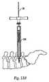
インプラントを受け入れる椎骨を含んだ脊椎のX線撮影画像を撮る。X線撮影画像から、患者の背中の挿入箇所を決める。次に、患者の背中の切開を行い、侵襲性の少ないシステムを用いる開口を形成する。次に、開口を拡張させる。当業者であれば、以下にさらに詳細に説明する装置を含む任意の数の装置を用いて、患者の開口の拡張を行うことを理解すべきである。[A. Extension tool)
X-ray images of the spine including the vertebrae receiving the implant are taken. The insertion position of the patient's back is determined from the X-ray image. Next, an incision is made in the patient's back to form an opening using a less invasive system. Next, the opening is expanded. One skilled in the art should understand that any number of devices, including those described in more detail below, may be used to dilate the patient's opening.
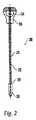
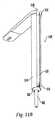
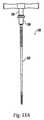
〔1.トロカール及びガイドワイヤ〕
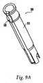
図1に示すように、トロカール100は、近位端部120及び遠位端部30を有する細長い部材110であるのがよい。トロカール100を、例えば、X線透視誘導を用いて、患者の切開部から挿入し、椎骨に係合させるのがよい。トロカール100の遠位端部130は、椎骨の皮質を貫通する孔をあける及び/又は形成するための先端部135を有するのがよい。さらに、トロカール100は、その遠位端部130に細長い前部分102を有するのがよい。細長い前部分102は、開口のサイズを増大させ、椎骨への経皮的な通路を形成するのを助ける。また、変形実施形態では、トロカール100の遠位端部130は、椎骨に係合してトロカール100を椎骨の所定の位置に保持するためのねじ山(図示せず)を有していてもよい。[1. Trocar and guide wire)
As shown in FIG. 1, the
トロカール100の近位端部120は、ハンドル125を追加的に有するのがよい。ハンドル125は、操作者がトロカール100を使用/操作するのをより容易にする。ハンドル125は、細長い部材110と一体に形成されていてもよいし、或いは、近位端部120に機械的に接合されていてもよい。ハンドル125は、X線透視観察下において即ちX線を用いるときに見えなくなるように、X線透過性であるのがよい。さらに、ハンドル125は、取り外しできるように構成されていてもよい。1つの実施形態では、ハンドル125は、T字形状である。別の実施形態では、ハンドル125の形状は、球状である。さらに、トロカール100は、近位端部120から遠位端部130まで延びるチャネル140を含むのがよい。 The proximal end 120 of the
ガイドワイヤ又はロッド150をトロカール100の近位端部120のところでチャネル140の中に挿入し、トロカール100によって形成された椎弓根内の孔の中に配置する。ハンドル125を有する実施形態では、ガイドワイヤ150をハンドル125の中に挿入してもよい。図1に示すガイドワイヤ150を用いて、種々の装置及び/又はインプラントを患者内に且つ脊椎に向かって案内する。例えば、ガイドワイヤ150を用いて、拡張器、挿入/作業用カニューレ、ドリル、ねじ回し、及びインプラント(例えば、骨ねじ)を脊椎上の箇所に案内する。本明細書に説明する任意の装置は、ガイドワイヤ150を用いることなしに患者に挿入されてもよいことに留意すべきである。ガイドワイヤ150を、それが椎骨に係合するまでチャネル140を通して下方に挿入する。その後、手術用木槌又は他の打ち込み器具(図示せず)を用いて、ガイドワイヤ150を、トロカール100によって形成された孔に打ち込む。このように、ガイドワイヤ150を椎骨に固定する。 A guidewire or
操作者がガイドワイヤ150を椎骨に打ち込むことを助けるために、ガイドワイヤ150は、その近位端部154に配置されたキャップ152を有するのがよい。このような構成は、木槌又は他の器具をガイドワイヤ150に押し当ててそれを打ち付けるための拡大した表面を操作者に提供する。キャップ152は、金属、プラスチック又はゴムで作られてもよいし、繰り返される衝撃に耐えることができるその他の任意の材料で作られてもよい。さらに、キャップ152は、任意の形状(例えば、円形、多角形、球形状)又はサイズを有する。さらに、キャップ152は、ガイドワイヤ150を骨に埋め込むために用いる別の構成部品(例えば、スラップハンマ)と係合可能であるのがよい。 To help the operator drive the
トロカール100/ガイドワイヤ150を挿入するステップを、処置が行う椎骨の数及び/又はインプラントの数に応じて、別個の切開部又は同じ切開部を通して任意の回数繰り返すのがよい。 The step of inserting the
〔2.拡張器〕
ガイドワイヤ150を所定の位置に配置したら、トロカール100を患者の身体から取り外す。2004年7月2日に出願された「Sequential Dilator System」と題する米国特許出願番号第10/884,705号(この米国特許出願の内容全体を本明細書に援用する。)に開示されているような一連の拡張器システムを用いて、患者の開口を拡大する。しかしながら、任意の拡張器システムを、侵襲性の少ないシステムと共に用いてもよいことを理解すべきである。[2. Expander]
Once
拡張器挿入装置、例えば、図2に示す拡張器挿入装置200を、ガイドワイヤ150に伝わらせて、椎骨の近くの手術部位に向かって下方に挿入する。拡張器挿入装置200は、ガイドワイヤ150を受け入れる中央ボア212を含む細長いシャフト210を有するのがよい。拡張器挿入装置200は、その近位端部214にあるハンドル216と、その遠位端部218にある弾丸形状の先端部220とを有する。ハンドル216を取り外し可能にすることにより、拡張器挿入装置200の上に1つ又は2つ以上の拡張器チューブ350(図3A)を挿入することが可能である。さらに、弾丸形状の先端部220は、開口を拡張させ、椎骨への拡張した経皮通路を形成するのを助ける。しかしながら、先端部220は、任意の形状であり、拡大されていてもよいし、拡大されていなくてもよい。 A dilator insertion device, such as the dilator insertion device 200 shown in FIG. 2, is inserted down the
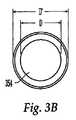
拡張器挿入装置200を所定の箇所に配置したら、拡張器挿入装置200の上に、図3Aに示すような1つ又は2つ以上の異なる大きさの拡張器チューブ350を挿入する。拡張器挿入装置200を用いないで、1つ又は2つ以上の拡張器チューブ350をガイドワイヤ150の上に直接挿入してもよいことに留意すべきである。拡張器チューブ350は、細長いシャフト352を有し、この細長いシャフト352は、拡張器挿入装置200及び/又は他の拡張器350を収容するように寸法及び形状が決められ且つ細長いシャフト352を貫通するチャネル354を有している。さらに、拡張器チューブ350は、患者の身体内における拡張器350の深さの視覚的表示を操作者に与えるマーキング355を有するのがよい。 Once the dilator insertion device 200 is in place, one or more different
内径D(図3B)を有する第1の拡張器350を、拡張器挿入装置200の上に配置し、椎骨の近くの手術部位まで下げる。しかしながら、拡張器挿入装置200及び第1の拡張器350を互いに取り付け、単一のユニットとして身体に挿入してもよいことを理解すべきである。次に、第1の拡張器350から挿入装置200を取り外す。その後、第1の拡張器350の上に、第1の拡張器350の外径D’よりも大きい内径を有する第2の挿入装置350を挿入する。このプロセスを、開口が、外科医により所望され且つ処置を行うのに適切な寸法(例えば、インプラント及び/又は器具を収容するのに十分に大きい寸法)に拡張されるまで、順番により大きい拡張器350を用いて何度も繰り返すのがよい。また、処置のために多数の開口を用いる実施形態では、各々の開口について拡張プロセスを繰り返すのがよい。 A
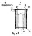
1つの実施形態では、最も大きい拡張器350を所定の箇所に配置した後、作業用カニューレ475(図4A及び図4B)を拡張器350の上に配置し、手術される椎骨の近くの手術部位まで下げる。作業用カニューレ475は、外科医がアクセス可能なままである近位端部476と、作業用カニューレ475を挿入した時に手術部位に隣接して配置される遠位端部478とを有する。さらに、作業用カニューレ475は、チャネル480を有し、このチャネル480は、近位端部476の開口497から遠位端部478の開口498まで延び、このチャネル480の中を通して操作者がインプラント及び手術用器具を挿入するのがよい。作業用カニューレ475は、近位端部476から遠位端部478まで一定の直径を有するのがよい。さらに、作業用カニューレ475は、手術中に外科医が作業用カニューレ475を掴むことを可能にするための及び/又は作業用カニューレ475を手術台に固定することを可能にするためのハンドル482を近位端部476に有するのがよい。このように、手術中、作業用カニューレ475を静止状態に保持するのがよい。 In one embodiment, after placing the
作業用カニューレ475を所定の箇所に配置したら、全ての拡張器350及び/又はガイドワイヤ150を身体から取り外す。1つの実施形態では、インプラント及び器具を手術部位に案内するために、ガイドワイヤ150を所定の箇所に維持してもよい。しかしながら、各拡張器350の上にそれよりも大きい拡張器350を配置した後、各拡張器350を取り外すのがよい。処置の異なる部分を、異なる作業用カニューレ475によって行ってもよい。作業用カニューレ475が、多数の椎骨を露出させるのに十分大きいものである場合、処置全体を単一の作業用カニューレ475によって、即ち、患者に別の開口を形成することなしに行ってもよい。しかしながら、拡張器350に加えて又はその代わりに、開口を拡張するその他の手段、例えば開創器を用いてもよい。 Once the working
〔3.開創器〕
2004年8月13日に出願された「Multiple−Blade Retractor」という名称の米国特許出願(代理人整理番号8932−804−999(708716−999781)、その内容全体を本明細書に援用する)に開示されるような開創器500を用いて、患者の開口を拡大するのがよい。1つの実施形態では、閉鎖位置(図5A)の開創器500のブレード502を、開口の中に且つ少なくとも1つの拡張器350の上に配置する。別の実施形態では、拡張器350を用いることなく、開創器500を患者の開口内に直接挿入してもよい。開創器500を患者の開口内に置き、次いで、開創器500のハンドル504を互いに押して、ブレード502を広げる(図5B)。ロック機構506を用いて、ブレード502を開放位置にロックするのがよい。ロック機構506は、ねじ山付きロッド508と、ナット510とを含むのがよい。ナット510を、それがハンドル504に係合するまで、ねじ付きロッド508上で回転させる。しかしながら、開創器を開放位置に保持するために、開創器500をロックする任意の手段も用いることができる。引き続いて行われる全ての外科的処置は、開創器500のブレード502によって形成された拡大した開口内で、即ち、ブレード502間で行うのがよい。当業者であれば、患者の開口を拡大するために、外科的技術分野において周知のその他の任意の開創器を用いてもよいことを認識すべきである。[3. (Retractor)
US patent application entitled “Multiple-Blade Retractor” filed on August 13, 2004 (Attorney Docket No. 8932-804-999 (708716-999781), the entire contents of which are incorporated herein by reference). A
〔B.埋め込みツール〕
〔1.骨ねじ〕
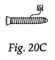
図6A及び図6Bに示す本発明の1つの実施形態では、椎骨に挿入すべきインプラントは、多軸式のねじ650であるのがよい。しかしながら、任意のねじが、脊椎ロッドを受け入れる寸法及び形態に構成されたロッド受け入れチャネルに組み込まれ、又は、固定することができる限り、かかる任意のねじを侵襲性の少ないシステムと共に用いることが考えられる。骨ねじ650は、シャンク部分654と、このシャンク部分654に作動可能に接続されたヘッド部分652とを有する。シャンク部分654にねじ山が設けられるのがよく、ねじ山はタッピンねじであるのがよい。骨ねじ650は、ヘッド部分652がシャンク部分654に関節式に連結され且つそれに対して回転可能であるような多軸式である。シャンク部分654は、ヘッド部分652と別個の部品であり、ヘッド部分652に係合するのがよい。シャンク部分654をヘッド部分652と一体にしてもよく、その場合、シャンク部分654とヘッド部分652との間の移動はない。[B. (Embedding tool)
[1. (Bone screw)
In one embodiment of the invention shown in FIGS. 6A and 6B, the implant to be inserted into the vertebra may be a
シャンク部分654は、ヘッド部分652内に受け入れられる近位端部658を有する。1つの実施形態では、シャンク部分654は、ヘッド部分652内にスナップ嵌めされるのがよい。シャンク部分654の近位端部658は、例えば、手術用ツールの六角形部分を受け入れるようにそれに対応した六角形形態等の手術用ツール係合凹部674を有するのがよい。さらに、シャンク部分654は、ガイドワイヤ150を受け入れる中央の軸方向チャネル660を有するのがよく、それにより、ねじ650を椎骨の近くの手術部位に案内することができる。他の形状及び形態のシャンク部分654及びヘッド部分652を用いて、ヘッド部分652とシャンク部分654との間の多軸式回転を行ってもよい。 The
図6A及び図6Bに示すように、ヘッド部分652は、円筒形であるのがよく、ベース部分662と、互いに間隔をおいて配置された2つのアーム664とを有するのがよい。アーム664は、手術用ツール(例えば、以下に説明される種々の挿入カニューレ)に係合するための面取り縁部668及び凹部670を有するのがよい。1つの実施形態では、アーム664は、種々の挿入カニューレ及び/又は他の手術用ツールに係合する雄ねじ(図示せず)を有する。ヘッド部分652は、中央ボア667を有するのがよい。中央ボア667は、シャンク部分654の近位端部658がヘッド部分652の遠位端665の遠位開口663を貫いて延びるように、ヘッド部分652を貫通するのがよい。アーム664は、中央ボア667と交差するチャネル666を形成するのがよい。チャネル666は、固定ロッドを受け入れることができる任意の形状(例えば、U字形状)である。さらに、ヘッド部分652は、キャップ681及び/又は外科用器具(例えば、ねじ回し、挿入カニューレ等)の雄ねじ680に係合させるための雌ねじ672をボア667の壁に有するのがよい。キャップ681は、ボア667内に受け入れられるのがよい。固定ロッドを骨ねじ内に保持するために、ヘッド部分652の近位端部671のところで異なる機構と相互作用するその他のキャップを用いてもよい。 As shown in FIGS. 6A and 6B, the
〔2.挿入カニューレ〕
インプラント(例えば、ねじ、固定ロッド)を挿入するために、挿入カニューレを用いるのがよい。しかしながら、当業者であれば、全ての処置に対して挿入カニューレを用いる必要がないことを理解すべきである。挿入カニューレを骨ねじ650及び/又はその他のツール(例えば、ねじ回し)に接続し、1つのユニットとして、作業用カニューレ475及び/又は開創器500によって形成された開口を通して挿入するのがよい。別の実施形態では、挿入カニューレを患者内に配置した後、骨ねじ650及び/又はその他のツールを挿入カニューレに挿入してもよい。ガイドワイヤ150を用いる実施形態では、挿入カニューレ、骨ねじ650及び/又はその他のツール(例えば、ねじ回し)をガイドワイヤ150に沿って椎骨まで挿入するのがよい。[2. Insertion cannula
An insertion cannula may be used to insert an implant (eg, screw, fixation rod). However, one of ordinary skill in the art should understand that an insertion cannula need not be used for all procedures. The insertion cannula may be connected to the
用いられる挿入カニューレのタイプは、例えば、外科医の好み、身体の生体組織、及び/又は外科的処置の要件によって決まる。特に、挿入カニューレは、固定ロッドを骨ねじに挿入することができる方法を要因として選択される。幾つかの実施形態では、固定ロッドを骨ねじの側面から挿入するように、挿入カニューレを設計するのがよい。これらの実施形態では、骨ねじを患者に挿入した切開部とは別個の切開部を通して、固定ロッドを挿入するのがよい。他の実施形態では、脊椎ロッドを骨ねじの上部を貫くように挿入するように、挿入カニューレを設計してもよい。また、骨ねじを挿入した切開部と同じ切開部を通して、脊椎ロッドを挿入してもよい。他の実施形態では、ロッドを骨ねじの上部又は側部のいずれかから挿入することを可能にするように、挿入カニューレを構成するのがよい。 The type of insertion cannula used will depend, for example, on surgeon preferences, body anatomy, and / or surgical procedure requirements. In particular, the insertion cannula is selected due to the manner in which the fixation rod can be inserted into the bone screw. In some embodiments, the insertion cannula may be designed to insert the fixation rod from the side of the bone screw. In these embodiments, the fixation rod may be inserted through an incision separate from the incision in which the bone screw is inserted into the patient. In other embodiments, the insertion cannula may be designed to insert the spinal rod through the top of the bone screw. Further, the spinal rod may be inserted through the same incision as the incision into which the bone screw is inserted. In other embodiments, the insertion cannula may be configured to allow the rod to be inserted from either the top or side of the bone screw.
作業用カニューレ475又は開創器500を用いない実施形態では、挿入カニューレを、挿入装置200(挿入カニューレ内に嵌合するように特別に設計される)に接続するのがよく、患者の切開部を通して、挿入装置200と共に単一のユニットとして挿入するのがよい。ガイドワイヤ150を用いて、挿入装置/カニューレ構成を椎骨まで案内するのがよい。挿入カニューレから、挿入装置200及び/又はガイドワイヤ150(用いられる場合)を引き出し、挿入カニューレを通して処置の全工程を行うのがよい。挿入カニューレを通して、例えば、ドリル、骨ねじ、ねじ回し、固定ロッド、及び他の外科用ツールを挿入するのがよい。他の実施形態では、何らかの付加的な器具を用いることなしに、挿入カニューレを患者の開口に直接挿入してもよい。かくして、挿入カニューレは、開口を拡張させ/縮める機能を実施する。 In embodiments that do not use the working
しかしながら、任意の組み合わせの器具(例えば、トロカール100、ガイドワイヤ150、挿入装置200、拡張器350、作業用カニューレ475、及び/又は開創器500)を用いて、患者の身体への挿入カニューレの挿入を助けてもよいことに留意すべきである。 However, any combination of instruments (eg,
侵襲性の少ない処置を行う際、後で説明するような挿入カニューレを2つ以上用いて、例えば、骨ねじ650を隣接した椎骨に挿入し、骨ねじ650を保持し、それを操作するのがよい。挿入カニューレは、患者の別個の切開部を通して挿入され及び/又は同じ切開部を通して挿入される。例えば、作業用カニューレ475を用いる実施形態では、別個の切開部が、別個の作業用カニューレ475を有し、別個の挿入カニューレを各々の作業用カニューレ475を通して椎骨まで挿入するのがよい。作業用カニューレ475が十分に大きい場合には、多数の挿入カニューレを作業用カニューレ475に挿入してもよいことを認識すべきである。さらに、開創器500を用いる実施形態では、開創器500によって形成された開口を通して、多数の挿入カニューレを挿入するのがよい。このような実施形態では、作業用カニューレ475又は開創器500を通して、処置全体を行うことができる。 When performing a less invasive procedure, using two or more insertion cannulas as described below, for example, inserting a
挿入カニューレの1つの利点は、ヘッド部分652の配向を各々のカニューレの近位端部を介して目に見えることである。したがって、外科医は、チャネル666内の固定ロッドの位置を確認することができる。手術部位を覗くことができる外科医の能力をさらに向上させるために、後で説明する任意の挿入カニューレは、光源を有していてもよい。さらに、挿入カニューレは、手術部位の外科医の視野を妨げる可能性がある流体及び組織を除去し、これにより手術部位の外科医の視野が改善されるように、吸引・洗浄システムを含んでいてもよい。さらに、顕微鏡又は内視鏡(図示せず)を挿入カニューレに取り付け、拡大した手術部位の視野を得てもよい。また、処置が挿入カニューレの安定化を必要とする場合、例えば、SYNTHES(登録商標)の「Spine Synframe Access and Retractor System」のような、任意の数の取り付け具の1つに、挿入カニューレを連結してもよい。これらの取り付け具は、例えば、手術台に取り付けられ、挿入カニューレを患者に対する所定の位置に保持し、これにより手術中に外科医又は看護師が挿入カニューレを保持する必要性を排除することが可能である。 One advantage of the insertion cannula is that the orientation of the
さらに、本明細書に説明される任意の挿入カニューレの構成部品は、例えば、金属、プラスチック、ゴム、材料の組み合わせ、又は複合材料で作られる。例えば、構成部品は、ステンレス鋼、チタン、アルミニウム、合金、炭素繊維複合材、又はポリマー(例えば、ポリ塩化ビニル(PVC)、ポリエチレン、様々な種類のポリエステル、ポリカーボネート、Teflon(登録商標)コーティングを施した金属、ポリエーテルエーテルケトン(PEEK)、超高分子量ポリエチレン(UHMWPE))から作られる。また、挿入カニューレの構成部品は、反射防止コーティングを有してもよく、及び/又はX線透過性としてもよい。さらに、挿入カニューレの構成部品は、例えば、鋳造、押出し成形、射出成形、圧縮成形、鍛造、機械加工、又はトランスファー成形によって作られる。 Further, any insertion cannula component described herein may be made of, for example, metal, plastic, rubber, a combination of materials, or a composite material. For example, the component may be stainless steel, titanium, aluminum, alloy, carbon fiber composite, or polymer (eg, polyvinyl chloride (PVC), polyethylene, various types of polyester, polycarbonate, Teflon® coating). Metal, polyetheretherketone (PEEK), ultra high molecular weight polyethylene (UHMWPE)). Also, the insertion cannula component may have an anti-reflective coating and / or may be x-ray transmissive. Further, the components of the insertion cannula are made, for example, by casting, extrusion, injection molding, compression molding, forging, machining, or transfer molding.
挿入カニューレの種々の構成部品を作るために用いられる材料を決定するとき、(例えば、オートクレーブ、病院における滅菌のために用いられる洗浄製品を使用する)滅菌/洗浄に耐える能力、重量、耐久性、汚染に対する耐性(例えば、血液又は手術に用いられる物質からの)、及び特に手術中に一般に用いられるゴム手袋を用いて構成部品を把持する能力を含む、種々の要因を考えることができる。 When determining the materials used to make the various components of the insertion cannula, the ability to withstand sterilization / washing (eg, using autoclaves, cleaning products used for hospital sterilization), weight, durability, Various factors can be considered, including resistance to contamination (eg, from blood or materials used in surgery) and the ability to grip components with rubber gloves commonly used during surgery, among others.
さらに、以下に説明される挿入カニューレのカニューレシャフトは、円形の断面を有するものとして示すことができるが、断面は、例えば、楕円、正方形、矩形、三角形、又は他の多角形といった任意の形状にすることができる。 Furthermore, the cannula shaft of the insertion cannula described below can be shown as having a circular cross section, but the cross section can be any shape, for example, oval, square, rectangular, triangular, or other polygonal shape. can do.
〔a.側部挿入カニューレ〕
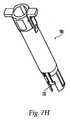
図7Aに示すように、挿入カニューレ700は、外側カニューレシャフト720内に収容された内側カニューレシャフト710を有する。さらに、図7B及び図7Cに示すように、内側カニューレシャフト710は、近位端部712と、遠位端部714と、近位端部712から遠位端部714まで延びるボア716とを有する。ボア716は、中心軸線718を有し、脊椎インプラント(例えば、骨ねじ)及び/又は外科用器具を受け入れる寸法及び形態を有するのがよい。ボア716は、ガイドワイヤ150、挿入装置200、及び/又は少なくとも1つの拡張器350の上に配置されるように構成されてもよい。チャネル又はスロット722が、内側カニューレシャフト710の遠位端部714に配置され、中心軸線718に対してある角度(例えば、直角)で延びるのがよい。チャネル又はスロット722は、U字形状であるのがよいが、他の形状であることも考えられ、以下により詳細に説明するように、チャネル又はスロット722を通して挿入することができる固定ロッドの少なくとも一部分を収容することもできる。[A. Side insertion cannula
As shown in FIG. 7A, the
内側カニューレシャフト710の内径は、例えば、約3mm〜約20mm、より好ましくは約12mm〜約15mmである。しかしながら、内径は、骨ねじ650及び/又はツールを内側カニューレシャフト710の中に通して配置することができる限り、任意の寸法である。内側カニューレシャフト710の外径は、例えば、約3mm〜約20mm、より好ましくは約14mm〜約17mmである。さらに、内側カニューレシャフト710の長さは、例えば、約40mm〜約160mm、より好ましくは約110mm〜約130mmである。チャネル又はスロット722の幅は、例えば、約3mm〜約10mm、より好ましくは約4mm〜約7mmである。チャネル又はスロット722の高さはまた、例えば、約3mm〜約20mm、より好ましくは約10mm〜約14mmである。これらの寸法は、後で説明する図8Bの内側カニューレシャフトにも適用可能であることに留意すべきである。 The inner diameter of the
図7D及び図7Eは、外側カニューレシャフト720の実施形態を示す。外側カニューレシャフト720は、近位端部724と、遠位端部726と、近位端部724から遠位端部726まで延びるボア728とを有する。ボア728は、中心軸線735を有し、内側カニューレシャフト710を受け入れる大きさ及び形態を有するのがよい。後で明らかになる理由で、外側カニューレシャフト720がその全長にわたって内側カニューレシャフト710の外面に沿って摺動することを可能にするために、外側カニューレシャフト720の長さは、内側カニューレシャフト710の長さよりも短いのがよい。また、外側カニューレシャフト720の遠位端部726は、内側カニューレシャフト710の遠位端部714と緊密に係合するように、内向きにテーパするのがよい。 7D and 7E show an embodiment of the
外側カニューレシャフト720の内径は、内側カニューレシャフト710の外径よりも大きく、外側カニューレシャフト720の外径は、例えば、約3mm〜約20mm、より好ましくは約16mm〜約19mmである。さらに、外側カニューレシャフト720の長さは、例えば、約20mm〜約140mm、より好ましくは約70mm〜約80mmである。これらの寸法は、後で説明する図8Eの外側カニューレシャフトにも適用可能であることに留意すべきである。 The inner diameter of the
内側カニューレシャフト710に対する外側カニューレシャフト720の回転を防止するために、及び/又は、2つの構成部品を整列させた状態に保持するために、外側カニューレシャフト720は、ボア728の内壁に配置された少なくとも1つの突起部740(図7D)を有し、この突起部740は、内側カニューレシャフト710の壁の少なくとも1つのスロット750(図7B参照)と係合する。1つの実施形態では、突起部740は、止めばね752を外側カニューレシャフト720に係合させるように開口760(図7F)を貫通するねじ、ピン、又はボルトであってもよい。変形例として、内側カニューレシャフト710が突起部を有し、外側カニューレシャフト720がスロットを有していてもよい。突起部740は、スロット750内を移動するのがよい。上記回転を防ぎ、及び/又は、内側カニューレシャフト710及び外側カニューレシャフト720を互いに整列させた状態に維持するその他の方法を考えてもよい。例えば、内側カニューレシャフト710及び外側カニューレシャフト720は、互いに対応する平坦な壁部分を有していてもよい。 In order to prevent rotation of the
付加的に、外側カニューレシャフト720の近位端部724は、少なくとも1つのハンドル部分を有し、操作者が、外側カニューレシャフト720を内側カニューレシャフト710に沿って移動させることを可能にするのがよい。使用の際、操作者は、ハンドル部分の周りに自分の指を巻き付けるのがよい。図7Eの実施形態に示すように、外側カニューレシャフト720は、正反対の位置にある一対のハンドル738を有するのがよい。ハンドル738は、近位端部724と一体形成されてもよいし、例えば、溶接、接着又は機械的な手段(例えば、ねじ、ボルト)によって近位部端724に取り付けられてもよい。さらに、内側カニューレシャフト710と同様、外側カニューレシャフト720は、その遠位端部726を貫通するチャネル又はスロット727を有するのがよい。チャネル又はスロット727は、内側カニューレシャフト710のチャネル又はスロット722と整列し、その結果、固定ロッドの少なくとも一部分をチャネル又はスロット722、727を通して挿入することができる。チャネル又はスロット727の幅は、例えば、約3mm〜約10mm、より好ましくは約5mm〜約8mmである。チャネル又はスロット727の高さは、例えば、約3mm〜約10mm、より好ましくは約5mm〜約8mmである。チャネル又はスロット727の寸法は、後で説明する図8Eのチャネル又はスロットにも適用されることに留意すべきである。 Additionally, the
図7F及び図7Gは、挿入カニューレ700内の骨ねじ650の配置を示す。骨ねじ650を、内側カニューレシャフト710の遠位端部714のボア716内に配置するのがよく、骨ねじ650及び挿入カニューレ700を、単一のユニットとして患者に挿入するのがよい。挿入カニューレ700が既に患者内に配置されている別の処置においては、引き続き、骨ねじ650を近位端部712から遠位端部714までボア716に沿って挿入するのがよい。骨ねじ650、特にそのヘッド部分652を挿入カニューレ700に対して固定するために、外側カニューレシャフト720の遠位端部726が内側カニューレシャフト710の近位端部712に近づいて配置される第1の位置(図7F参照)から、外側カニューレシャフト720の遠位端部726が内側カニューレシャフト710の遠位端部714に近づいて配置される第2の位置(図7G参照)まで、外側カニューレシャフト720を移動させることができる。操作者は、骨ねじ650を挿入カニューレ700に対して固定する前に、チャネル又はスロット722、727を骨ねじ650のヘッド部分652のチャネル666と整列させるのがよい。 7F and 7G show the placement of the
外側カニューレシャフト720は、撓むことができる止めばね752(図7F参照)を有するのがよく、止めばね752は、第1の位置において溝756に係合し、第2の位置において溝758(図7B参照)に係合する。特に、止めばね752の突起部(図示せず)は、ハンドル738の開口758を通り且つ溝756、758に係合することができる。このような構成は、外側カニューレシャフト720が内側カニューレシャフト710に対して第1の位置又は第2の位置にあることを、操作者に触覚的に及び/又は聴覚的に示すことができる。1つの実施形態では、止めばね752の突起部と溝756、758との係合により、外側カニューレシャフト720を内側カニューレシャフト710上の第1の位置及び/又は第2の位置にロックさせることができる。 The
図7Gに示す第2の位置において、外側カニューレシャフト720の遠位端部726が、1つ又は2つ以上の可撓性部材736を押すのがよい。このことにより、可撓性部材736が、骨ねじ650のヘッド部分652の凹部670に係合する。こうした係合は、骨ねじ650が挿入カニューレ700に対して軸線方向に移動することを防止する。外側カニューレシャフト720は、アーム737(図7A及び図7H参照)を押すのがよい。アーム737は、骨ねじ650のヘッド部分652に係合し、特に、アーム737は、ヘッド部分652のチャネル666内に嵌合するのがよい。このような位置において、アーム737は、骨ねじ650のヘッド部分652が挿入カニューレ700に対して回転移動することを防止する。このように、ヘッド部分652が、シャンク部分654の周りに枢動運動することを依然として可能にしながら、骨ねじ650のヘッド部分652を挿入カニューレ700に対して軸線方向及び回転方向に固定することができる。幾つかの実施形態では、外側カニューレシャフト720を第2の位置に移動させる前に、可撓性部材736及び/又はアーム737が、挿入カニューレ700に対するねじ650の軸線方向及び/又は回転方向に固定してもよいことに留意すべきである。操作者が挿入カニューレ700を使用して、1つの骨ねじ650のチャネル666を別の骨ねじ650のチャネル666と整列させるように1つの骨ねじ650のヘッド部分652を操作するのがよい。チャネル666同士が整列すると、インプラント(例えば、固定ロッド)をチャネル666の中に挿入することができる。 In the second position shown in FIG. 7G, the
付加的に、操作者がヘッド部分652を整列させるのを助けるために、内側カニューレシャフト710に、平坦な面713、マーク、若しくは刻み目(図示せず)を設けるのがよい。平坦な面713は、処置中に身体の外側に配置されるのがよく、身体内に配置されるチャネル又はスロット722、727及び/又はチャネル666の配向の視覚的なインジケータを操作者に提供する。平坦な面713は、操作者が、チャネル又はスロット722、727を身体内のチャネル666と整列させるのを助ける。 Additionally, the
図8Aは、挿入カニューレの別の実施形態である挿入カニューレ800を示す。挿入カニューレ700と同様、挿入カニューレ800は、外側カニューレシャフト820内に受け入れられる内側カニューレシャフト810を有している。図8B及び図8Cに示すように、内側カニューレシャフト810は、近位端部812と、遠位端部814と、近位端部812から遠位端部814まで延びるボア816とを有するのがよい。ボア816は、中心軸線818を定め、脊椎インプラント(例えば、骨ねじ)又は外科用器具を受け入れるような大きさ及び形態であるのがよい。チャネル又はスロット822が、内側カニューレシャフト810の遠位端部814に配置され、中心軸線818に対してある角度(例えば、直角)で延びるのがよい。チャネル又はスロット822は、U字形状であるのがよく(他の形状も考えられるが)、固定ロッドの少なくとも一部分を収容することができる。 FIG. 8A shows an
内側カニューレシャフト810の近位端部812は、1つ又は2つ以上の孔815を有するのがよい。孔815を用いて、隣接した挿入カニューレ800間の機構(図示せず)を接続することにより、カニューレを互いに対して定位置に配置してもよいし、互いに対してピボット運動させてもよい。1つの実施形態では、孔815を用いて、固定ロッドを身体内に導くための誘導機構を取り付けるのがよい。誘導機構が取り付けられた挿入カニューレ800を操作するとき、挿入カニューレ800は、椎骨に圧縮力又は延伸力を与えることができる。近位端部812は、手術部位をボア816を通して照明するために用いられる光源を台に載せるように又は固定するように構成されるのがよい。近位端部812は、他の装置に係合するように構成されてもよい。 The
図8D及び図8Eは、外側カニューレシャフト820の実施形態を示す。外側カニューレシャフト820は、近位端部822と、遠位端部824と、近位端部822から遠位端部824まで延びるボア826とを有するのがよい。ボア826は、中心軸線828を定め、内側カニューレシャフト810を受け入れるような大きさ及び形態であるのがよい。後で詳述する理由のために、外側カニューレシャフト820がその全長にわたって内側カニューレシャフト810の外面に沿って摺動することを可能にするために、外側カニューレシャフト820の長さは内側カニューレシャフト810の長さよりも短いのがよい。外側カニューレシャフト820の遠位端部824は、内側カニューレシャフト810の遠位端部814と緊密に係合するように、内向きにテーパするのがよい。 8D and 8E show an embodiment of the
外側カニューレシャフト820は、少なくとも1つの係合部分830を有するのがよい。係合部分830は、内側カニューレシャフト810の壁内のスロット838に係合させるための少なくとも1つの突起部836(すなわち、ボア816内の)を有するのがよい。図8Eのような、2つの係合部分830を有する1つの実施形態では、一方の係合部分830が可撓性であり、他方の係合部分830が外側カニューレシャフト820に対して固定されるのがよい。係合部分830は、可撓性であるのがよく、突起部836は、ノッチ840、842、844との間で解放可能にスナップ嵌めされるのがよい。このような構成により、外側カニューレシャフト820が内側カニューレシャフト810に対して回転することを防止し、及び/又は、内側カニューレシャフト810及び外側カニューレシャフト820を特定の配向に保持する(例えば、チャネル又はスロット822、827を互いに整列した状態に保持する)ことを可能にする。挿入カニューレ700と同様、内側カニューレシャフト810及び外側カニューレシャフト820を位置決めする他の手段も考えられる。また、スロット838は、突起部836を受け入れるための1つ又は2つ以上のノッチ840、842、844を有するのがよく、このような構成はまた、外側カニューレシャフト820を、所定の間隔で内側カニューレシャフト810に対して固定することを可能にする。 The
骨ねじ650は、内側カニューレシャフト810の遠位端部814のボア816内に配置され、骨ねじ650及び挿入カニューレ800は、単一のユニットとして患者に挿入されるのがよい。挿入カニューレ800が既に患者内に配置されている別の処置では、引き続いて、骨ねじ650を近位端部812から遠位端部814までボア816に沿って挿入するのがよい。 The
骨ねじ650を上述した挿入カニューレ700に取り付ける方法と同様に、骨ねじ650をカニューレ800に取り付けるのがよい。係合部分830の突起部836がノッチ840に係合する第1の位置から、係合部分830の突起部836がノッチ842又は844に係合する第2の位置まで、外側カニューレシャフト820を移動させる。操作者は、外側カニューレシャフト820を第2の位置に移動させる前に、チャネル又はスロット822、827を骨ねじ650のヘッド部分652のチャネル666と整列させるのがよい。 Similar to the method of attaching
第2の位置(図示せず)において、外側カニューレシャフト820の遠位端部824は、少なくとも1つの可撓性部材832を押すのがよい。しかしながら、多数の可撓性部材を用いてもよいことに留意すべきである。次いで、可撓性部材832、よって突起部834が、骨ねじ650のヘッド部分652の凹部670に係合する。可撓性部材832は、骨ねじ650が挿入カニューレ800に対して軸線方向に移動することを防止する。付加的に、外側カニューレシャフト820は、アーム837(図8A)を押してもよい。アーム837は、骨ねじ650のヘッド部分652に係合することができ、特に、アーム837は、ヘッド部分652のチャネル666内に嵌合されるのがよい。このような位置において、アーム837は、骨ねじ650のヘッド部分652が挿入カニューレ800に対して回転移動することを防止する。このように、骨ねじ650のヘッド部分652を挿入カニューレ800に対して軸線方向及び回転方向に固定することができる。同時に、ヘッド部分652は、シャンク部分654の近位端部658の周りにピボット運動することができる。幾つかの実施形態では、外側カニューレシャフト820を第2の位置に移動させる前に、可撓性部材832及び/又はアーム837が、カニューレ800に対する骨ねじ650の軸線方向及び/又は回転方向に固定できることに留意すべきである。 In a second position (not shown), the
操作者が挿入カニューレ800を使用して、1つの骨ねじ650チャネル666を別の骨ねじ650のチャネル666と整列させるように1つの骨ねじ650のヘッド部分652を操作し、インプラント(例えば、固定ロッド)をチャネル666の中に挿入するのがよい。内側カニューレシャフト810は、チャネル又はスロット822及び/又は827と同じ方向に配向されたチャネル813を有するのがよい。さらに、内側カニューレシャフト810は、チャネル又はスロット822が通る内側カニューレシャフト810の側面に配置された平坦面812aを有するのがよい。チャネル813及び/又は平坦面812aは、処置中に身体の外側に配置されるのがよく、チャネル又はスロット822、827及び/又は身体内のチャネル666の配向の視覚的インジケータを、操作者に提供することができる。このような構成はまた、操作者が、チャネル又はスロット822、827を身体内のチャネル666と整列させるのを助ける。 An operator uses the
図9Aは、挿入カニューレさらに別の実施形態である挿入カニューレ900を示す。システム900は、カニューレシャフト910と、細長い部品920とを有するのがよい。図9B及び図9Cに示すように、カニューレシャフト910は、近位端部912と、遠位端部914と、近位端部912から遠位端部914まで延びるボア916とを有し、ボア916は、軸線918を有している。チャネル又はスロット928は、カニューレシャフト910の遠位端部914を貫通し、固定ロッドの少なくとも一部分をチャネル又はスロット928の中に通すのがよい。カニューレシャフト910はまた、近位端部912と遠位端部914との間に延び且つ細長い部品920(図9D参照)を保持することができる凹部922を有している。図9Cに示す凹部922の形状は、それに対応する細長い部品920の形状を受け入れるように設計するのがよく、細長い部品920は、凹部922の中を上下方向に動くことができるが、軸線918に対して横方向に凹部から抜け出ることはできない。さらに、凹部922は、細長い部品920の突起部(図示せず)に係合するためのスロット924を有するのがよい。この構成では、細長い部品920が、カニューレシャフト910に対して分離する又はねじれることを防止し、凹部922内での細長い部品920の移動を案内する。 FIG. 9A shows an
カニューレシャフト910の内径は、例えば、約3mm〜約20mm、より好ましくは約12mm〜約15mmである。しかしながら、内径は、これを通して骨ねじ650及び/又はツールを配置することができる限り、任意の寸法である。カニューレシャフト910の外径は、例えば、約3mm〜約20mm、より好ましくは約15mm〜約18mmである。さらに、カニューレシャフト910の長さは、例えば、約40mm〜約160mm、より好ましくは約110mm〜約130mmである。チャネル又はスロット928の幅は、例えば、約3mm〜約10mm、より好ましくは約5mm〜約8mmである。チャネル又はスロット928の高さは、例えば、約3mm〜約20mm、より好ましくは約12mm〜約16mmである。 The inner diameter of the
図9Dに示すような細長い部品920は、近位端部930と、遠位端部932とを有する。細長い部品920の長さは、例えば、約20mm〜約140mm、より好ましくは約110mm〜約130mmである。さらに、細長い部品920は、操作者に細長い部品920を作動させるための部分を提供する拡大部分934を有するのがよい。拡大部分934は、細長い部品920上での操作者の把持を強化するために、刻み目のような表面処理を有するのがよい。 The
骨ねじ650は、カニューレシャフト910の遠位端部914のボア916内に配置され、骨ねじ650及び挿入カニューレ900は、単一のユニットとして患者に挿入されるのがよい。カニューレ900が既に患者内に配置されている別の処置においては、引き続き、骨ねじ650を近位端部912から遠位端部914までボア916に沿って挿入するのがよい。操作者は、骨ねじ650のヘッド部分652のチャネル666を用いて、チャネル又はスロット928を配向するのがよい。骨ねじ650を挿入カニューレ900に対して固定するために、細長い部品920の遠位端部932は、可撓性部材927に係合するのがよい。かかる位置において、細長い部品920は、可撓性部材927を骨ねじ650のヘッド部分652の方向に押すので、可撓性部材927が、ヘッド部分652の凹部670に係合する。このように、骨ねじ650のヘッド部分652をカニューレ900に対して固定することができる。幾つかの実施形態では、可撓性部材927は、細長い部品920が可撓性部材927に係合する前に、挿入カニューレ900に対する骨ねじ650の軸線方向に固定できることに留意すべきである。ヘッド部分652は、シャンク部分654の近位端部658に対してピボット運動することができる。このことにより、操作者が、固定ロッドの挿入に備えてヘッド部分652を操作することが可能になる。 The
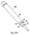
図10Aは、上述したカニューレと同様、骨ねじ650を保持するために用いることができるカニューレ1000を示す。図10A〜図10Dに示すように、カニューレ1000は、内側カニューレシャフト1010と、外側カニューレシャフト1020とを有するのがよい。内側カニューレシャフト1010は、近位端部1012と、遠位端部1014と、近位端部1012から遠位端部1014まで延びるボア1016とを有するのがよい。内側カニューレシャフト1010の遠位端部1014は、骨ねじ650のヘッド部分652の雌ねじ672に係合するための雄ねじ付き部分1015を有するのがよい。近位端部1012は、カニューレ1000の把持を容易にするために、例えば、刻み目等の表面処理を有するのがよい。付加的に、近位端部1012は、骨ねじ650のチャネル666の配向を示すことができる平坦部分、刻み目又はマーキング(図示せず)を有するのがよい。 FIG. 10A shows a cannula 1000 that can be used to hold a
内側カニューレシャフト1010の内径は、例えば、約3mm〜約20mm、より好ましくは約7mm〜約11mmである。内側シャフト1010の外径は、例えば、約3mm〜約20mm、より好ましくは約10mm〜約12mmである。さらに、内側カニューレシャフト1010の長さは、例えば、約40mm〜約160mm、より好ましくは約110mm〜約130mmである。 The inner diameter of the
図10Dに示すように、内側カニューレシャフト1010内に挿入装置1032を配置するのがよい。挿入装置1032は、内側カニューレシャフト1010のボア1016に挿入された外科用器具(例えば、ねじ回し)に係合するためのフィンガ1034を含むのがよい。したがって、外科用器具は、内側カニューレシャフト1010の近位端部1012内にスナップ嵌めされ、それと同時に、内側カニューレシャフト1010の内部で回転させられることが可能である。挿入装置1032はまた、外科用器具の一部に係合するための突起部1036を有するのがよい。 As shown in FIG. 10D, an insertion device 1032 may be placed within the
外側カニューレシャフト1020は、内側カニューレシャフト1010の上に配置され、その上で移動可能である。外側カニューレシャフト1020は、近位端部1022と、遠位端部1024と、外側カニューレシャフト1020を貫通するように近位端部1022から遠位端部1024まで延びるチャネル1025とを有するのがよい。外側カニューレシャフト1020は、内側カニューレシャフト1010の1つ又は2つ以上の凹部1040に係合するための1つ又は2つ以上の突起部1038を有するのがよい。1つの実施形態では、突起部1038は、外側カニューレシャフト1020の内面を一周する環状の突起部であるのがよい。さらに、凹部1040は、内側カニューレシャフトの外周面の環状凹部であるのがよい。このような構成により、外側カニューレシャフト1020が、内側カニューレシャフト1010に対して軸線方向に移動することが可能にする。
さらに、外側カニューレシャフト1020の外径は、骨ねじ650のヘッド部分652の外径と等しいのがよい。外側カニューレシャフト1020の直径とヘッド部分652の直径とが同じである構成においては、外側カニューレシャフト1020の遠位端部1024が、骨ねじ650のヘッド部分652の面取り縁部668に支持される。別の実施形態では、外側カニューレシャフト1020の直径は、骨ねじ650のヘッド部分652の直径よりも大きくてもよい。 Further, the outer diameter of the
外側カニューレシャフト1020の内径は、内側カニューレシャフト1010の外径より大きいのがよく、その外径は、例えば、約3mm〜約20mm、より好ましくは約12mm〜約15mmである。さらに、外側カニューレシャフト1020の長さは、例えば、約20mm〜約140mm、より好ましくは約100mm〜約110mmである。 The inner diameter of the
骨ねじ650をカニューレ1000に対して固定するために、内側カニューレシャフト1010の雄ねじ付き部分1015を、骨ねじ650(図6A参照)のヘッド部分652の雌ねじ付き部分672に係合させる。しかしながら、内側カニューレシャフト1010を骨ねじ650に係合させるための任意の手段が考えられることに留意すべきである。図10Dに示すように、外側カニューレシャフト1020は、その近位端部1022が内側カニューレシャフト1010の近位端部1012に係合する後方位置にある。いったん内側カニューレシャフト1010がヘッド部分652に係合したら、外側カニューレシャフト1020を内側カニューレシャフト1010の下方に移動させ、突起部1038を凹部1040内で移動させる。また、外側カニューレシャフト1020の遠位端部1024は、骨ねじ650のヘッド部分652に係合する。特に、図10Aに示すように、外側カニューレシャフト1020は、ヘッド部分652の平行なアーム664の間の空間に(すなわち、チャネル666の上部に)挿入することができる、拡張部分1026を有することができる。次に、骨ねじ650をカニューレ1000に対して軸線方向及び回転方向に固定する。 To secure the
〔b.側部及び/又は上部挿入カニューレ〕
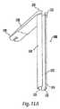
図11A及び図11Bは、骨ねじ650の上方又は側方からロッドを挿入するために用いることができる(すなわち、骨ねじ650を側部又は上部に取り付けることができる)挿入カニューレ1100を示す。挿入カニューレ1100は、細長い部材1110を含み、近位端部1112と、遠位端部1114と、近位端部1112から遠位端部1114まで延びるチャネル1116とを有している。さらに、挿入カニューレ1100は、チャネル1116と交わり且つ近位端部1112から遠位端部1114まで延びる第1の長手方向スロット1122を有している。しかしながら、第1のスロット1122は、任意の長さの細長い部材1110をカバーすることができ、近位端部1112からある距離で終わるのがよい。さらに、挿入カニューレ1100は、チャネル1116と交差する第2の長手方向スロット1123を有するのがよい。第2のスロット1123は、第1のスロット1122より短くてもよいし、長くてもよいし、これと同じ長さであってもよい。第2のスロット1123が必要でない場合もあることを認識すべきである。スロット1122、1123により、ロッドをチャネル1116の中で下降させて、骨ねじ650に挿入することを可能にする。[B. Side and / or upper insertion cannula]
11A and 11B show an
挿入カニューレ1100の遠位端部1114は、骨ねじ650のヘッド部分652に係合するのがよい(図11B参照)。例えば、遠位端部1114は、ヘッド部分652の凹部670に係合するための突起部(図示せず)を、細長い部材1110の内壁1125の上に有するのがよい。変形例として、遠位端部1114は、ヘッド部分652に緩く係合してもよい。一般に、カニューレ1100を用いて、骨ねじ650のヘッド部分652を操作することにより、固定装置をヘッド部分652に挿入して取り付けるのがよい。さらに、近位端部1112は、カニューレ1100を取り扱い且つ操作するためのハンドル1124を有するのがよい。また、ハンドル1124は、カニューレ1100を、例えば手術台に取り付けるための取り付け部分1129を有するのがよい。 The
図12Aは、骨ねじ650の上方又は側方から脊椎ロッドを挿入するために用いることができる挿入カニューレの別の実施形態を示す。挿入カニューレ1200は、近位端部1202と、遠位端部1204と、近位端部1202から遠位端部1204まで挿入カニューレ1200を貫いて延びるチャネル1206とを有するのがよい。さらに、挿入カニューレ1200は、チャネル1206と交差する少なくとも1つのスロット1208を有するのがよい。スロット1208により、ロッドをチャネル1206の中で下降させ、それを骨ねじ650に挿入することを可能にする。図12Aに示すように、1つより多いスロット1208を有する実施形態では、スロット1208は、2つのアーム1210及び1212を構成する。このような構成は、アーム1210及び1212を可撓性にし、骨ねじ650、特にそのヘッド部分652を、アーム1210とアーム1212との間にクリップ留め/スナップ嵌めさせる(図12B参照)。変形例として、スロット1208により、ロッドを骨ねじ650の側方から挿入することを可能にする。スロット1208は、挿入カニューレ1200の遠位端部1204から延び且つ近位端部1202からある距離だけ離れた位置まで延びるのがよい。2つ以上のスロット1208を有する実施形態では、スロット1208は、互いに同じ長さであってもよいし、互いに異なる長さであってもよい。 FIG. 12A shows another embodiment of an insertion cannula that can be used to insert a spinal rod from above or from the side of a
さらに、近位端部1202は、刻み目等の表面処理がされてもよいし、或いは、操作者の挿入カニューレ1200の把持を強化するためのグリップを有していてもよい。さらに、アーム1210及び/又は1212は、骨ねじ650のヘッド部分652の凹部670に係合するための突起部1214を有するのがよい。図12Bに示すように、挿入カニューレ1200が骨ねじ650に係合するとき、ヘッド部分652が回転する(すなわち、挿入カニューレ1200内で回転する)ことができるが、ヘッド部分652が挿入カニューレ1200に対して軸線方向に移動することができないように、骨ねじ650を固定するのがよい。1つの実施形態では、骨ねじ650を挿入カニューレ1200に対して固定することにより、回転移動を防止する。カニューレ1200を用いて、ヘッド部分652をシャンク部分654に対してピボット運動させてもよい。 Further, the proximal end 1202 may be surface-treated such as indents or may have a grip to enhance the grip of the operator's
挿入カニューレ1100、1200の内径は、例えば、約3mm〜約20mm、より好ましくは約12mm〜約16mmである。カニューレ1100、1200の内径は、これを通して骨ねじ650及び/又はツールを配置することができる限り、任意のサイズであることに留意すべきである。挿入カニューレ1100、1200の外径は、例えば、約3mm〜約20mm、より好ましくは約14mm〜約17mmである。さらに、挿入カニューレ1100、1200は、例えば、約40mm〜約200mm、より好ましくは約140mm〜約160mmである。スロット1208の幅は、例えば、約3mm〜約10mm、より好ましくは約5mm〜約8mmである。スロット1208の高さは、例えば、約30mm〜約160mm、より好ましくは約110mm〜約130mmである。 The inner diameter of the
〔3.ドリル〕
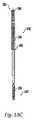
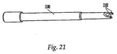
ドリル1350(図13A参照)を用いて、骨ねじ650を挿入するキャビティを椎骨内に形成するのがよい。ドリル1350を、作業用カニューレ475、開創器500及び/又は挿入カニューレ内に配置するのがよく、手術部位に向かって下方に移動させるのがよい。例えば、図13Bに示すようなガイドワイヤ150を用いる技術においては、ドリル1350を挿入カニューレ内に挿入し、ガイドワイヤ150によって挿入カニューレの下方に案内するのがよい。ドリル1350を、ガイドワイヤ150によって作業用カニューレ475又は開創器500の下方に案内してもよい。[3. Drill〕
A drill 1350 (see FIG. 13A) may be used to create a cavity in the vertebra for insertion of the
図13Aに示すように、ドリル1350は、ドリルビット1352と、ハンドル1362とを有するのがよい。ドリルビット1352及びハンドル1362は、一体の1つの部品であってもよいし、互いに接続された2つの部品であってもよい。例えば、ドリルビット1352は、継手1364によってハンドル1362に接続されてもよい。ハンドル1362を用いて、手作業で椎骨内に孔をあけることができる。ハンドル1362は、T字形状、球形、又は楕円形であってもよいし、その他の任意の形状であってもよい。しかしながら、ドリル1350がハンドル1362を有していなくてもよく、その代わりに、ドリルビット1352を動力ドリルに取り付けてもよいことに留意すべきである。このように、ドリルビット1352を電気的に又は空気圧で作動させてもよい。 As shown in FIG. 13A, the
図13C及び図13Dに示すように、ドリルビット1352は、シャフト1361と、シャフト1361の近位端部1355にある接続部分1354と、シャフト1361の遠位端部1357に位置する先端部1356とを有するのがよい。さらに、ドリルビット1352は、操作者がガイドワイヤ150の使用を望む処置のための中央ボア1358を有するのがよい。シャフト1361は、均一な直径を有していてもよいし、より大きな直径をもつ部分を有していてもよい。さらに、接続部分1354は、上述したように、ハンドルに取り付けられてもよいし、動力ドリルに接続されてもよい。ドリルビット1352の先端部1356を、当業者に周知のその他の骨切断ドリルビットと同様に構成するのがよい。 As shown in FIGS. 13C and 13D, the
さらに、1つの実施形態では、近位端部1354と遠位端部1356との間に窓1364を配置するのがよく、窓1364により、例えば、ガイドワイヤ150又は骨組織が、ドリルビット1352の中央ボア1358の中を移動するのを、操作者が見ることを可能にする。さらに、シャフト1361は、所定の間隔で離間配置されたマーキング1362を含むのがよい。このようなマーキング1362は、操作者が、骨組織内のドリルビット1352の深さを監視することを可能にする。 Further, in one embodiment, a
使用の際、ドリル1350を、作業用カニューレ475、開創器500、及び/又は挿入カニューレに挿入し、それを椎骨の近くに配置した後、ハンドル1362によって手動で、又は動力ドリルによって電気的に/空気圧で、ドリル1350を回転させ、ねじ650のようなインプラントを固定することができるキャビティを形成する。 In use, the
しかしながら、当業者であれば、骨の中にキャビティを形成する任意の手段を考えられることを理解すべきである。例えば、操作者は、椎骨の中にキャビティを形成するために、ドリル1350の代わりに、又はそれに加えて、千枚通し、プローブ、及び/又はタップを用いてもよい。さらに、幾つかの実施形態では、キャビティを形成するために、最初にドリル又は他のキャビティ形成ツールを用いることなく、骨ねじ650を直接骨に挿入してもよい。 However, it should be understood by those skilled in the art that any means of forming a cavity in the bone is conceivable. For example, an operator may use a threader, probe, and / or tap instead of or in addition to
〔4.インプラントポジショナ〕
図14は、作業用カニューレ465、開創器500、及び/又は挿入カニューレ内で骨ねじ650を配向するために用いることができるポジショナ1450を示す。ポジショナ1450は、シャフト1452と、このシャフト1452に作動的に接続された前部1454とを含むのがよい。前部1454は、骨ねじ650のヘッド部分652及び/又はシャンク部分654の近位端部658に係合するように構成されるのがよい。特に、前部1454は、凹部674に係合するための突起部1456と、ヘッド部分652のチャネル666に係合するための部分1458とを有するのがよい。ポジショナ1450はまた、シャフト1452上に取り付けることができ且つチャネル666内の部分1458の配向に合致したハンドル1460を有するのがよい。したがって、部分1458が骨ねじ650のチャネル666に係合するとき、ハンドル1460をチャネル666の方向と整列させる。このような構成は、身体の外側に、身体内のチャネル666の配向の視覚インジケータを、操作者に提供する。ハンドル1460を挿入カニューレ上の視覚インジケータ(例えば、平坦面713、812a)と位置合わせすることができる。[4. Implant positioner
FIG. 14 shows a positioner 1450 that can be used to orient the
使用の際、骨ねじ650を作業用カニューレ475、開創器500、及び/又は挿入カニューレ内に配置した後、ポジショナ1450を、骨ねじ650に係合可能である。代替的に、ポジショナ1450を用いて、作業用カニューレ475、開創器500、及び/又は挿入カニューレに沿って、骨ねじ650を挿入してもよい。操作者は、ポジショナ1450を操作し、骨ねじ650のヘッド部分652を回転させることができる。例えば、挿入カニューレに対するヘッド部分652の配向を固定する前、及び/又は固定ロッドを挿入する前、ポジショナ1450を用いて、チャネル666をそれに対応する挿入カニューレのチャネルと共に配向させることができる。代替的に、ヘッド部分652を挿入カニューレに対して既に固定した後、ポジショナ1450を用いて、骨ねじ650のヘッド部分652を操作してもよい。このように、ポジショナ1450を用いて、多数の骨ねじ650のチャネル666を整列させることができるので、固定ロッドを骨ねじ650の中を通るように挿入することができる。 In use, after positioning
〔5.ねじ回し〕
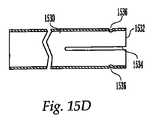
ねじ回し1500を、作業用カニューレ475、開創器500、及び/又は挿入カニューレ700、800、900、1100、1200内に配置するのがよく、骨ねじ650に係合することができる。図15A〜図15Dに示すように、ねじ回し1500は、シャフト1510と、ロックスリーブ1520と、保持スリーブ1530とを含むのがよい。シャフト1510は、遠位端部1514にある係合部分1516と、近位端部1512にある連結部分1513とを有する。さらに、シャフト1510にカニューレを挿入してもよい(すなわち、例えばガイドワイヤ150を受け入れるために、そこを貫通するチャネル(図示せず)を有する)。図15Bに示すように、係合部分1516は、骨ねじ650の凹部674に係合するように、六角形の形状にするのがよい。また、遠位端部1514は、骨ねじ650のヘッド部分652のU字形状チャネル666に係合するための少なくとも1つの肩部1518を有するのがよい。[5. screwdriver〕
A
さらに、連結部分1513は、ねじ回し1500を手動で操作するための、ハンドル1515(図15E参照)のようなハンドル部分に連結させるのがよい。ハンドル1515は、T字形状であってもよいし、その他の任意の形状であってもよい。ねじ回し1500にカニューレを挿入することができる実施形態では、ハンドル1515は、それを貫いて延びるチャネル(図示せず)を有するのがよく、このチャネルは、その中にガイドワイヤ150を挿入できるように、シャフト1510を貫いて延びるチャネルと整列するのがよい。代替的に、連結部分1513を、例えば動力ドリルなどのねじ回しを回転させるためのモータを有する装置に接続してもよい。ハンドル1515を、肩部1518の配向に合致させるようにシャフト1510上に配置してもよい。したがって、肩部1518が骨ねじ650のチャネル666に係合するとき、ハンドル1515をチャネル666の方向と整列させることができる。このような構成は、身体の外側からの、身体内のチャネル666の配向の視覚的インジケータを、操作者に提供することになる。ハンドル1515を挿入カニューレ上の視覚的インジケータ(例えば、平坦面713、812a)と整列させ、挿入カニューレのチャネルをチャネル666と整列させてもよい。 Further, the connecting portion 1513 may be connected to a handle portion such as a handle 1515 (see FIG. 15E) for manually operating the
図15Cは、ロックスリーブ1520を示す。ロックスリーブ1520をシャフト1510に沿って摺動できるように、ロックスリーブ1520のチャネル1528内にシャフト1510を配置するのがよい。ロックスリーブ1520は、グリップ端部1522と、ねじ係合端部1524とを含むのがよい。グリップ端部1522は、操作者がロックスリーブ1520をしっかりと掴むのを可能にするための処理(例えば、刻み付け)又はグリップをもつことができる表面1523を有するのがよい。別の実施形態では、グリップ端部1522は、掴むための少なくとも1つの凹み又は溝(図示せず)を有してもよい。ねじ係合端部1524は、ヘッド部分652の雌ねじ付き部分672に係合するための雄ねじ付き部分1526を有する。 FIG. 15C shows the
図15A及び図15Dに示すように、保持スリーブ1530は、ロックスリーブ1520の上に嵌合するような大きさであるのがよい。保持スリーブ1530は、挿入カニューレ700、800、900、1100、1200から延びるのがよく、操作者は、ねじ回し1500を保持する一方で、同時にねじ回し1500を回転させ、骨ねじ650を椎骨に挿入する。保持スリーブ1530がロックスリーブ1520に対して回転することができるが、軸線方向に移動することができないように、保持スリーブ1530をロックスリーブ1520に接続するのがよい。1つの実施形態では、保持スリーブ1530は、1つ又は2つ以上の長手方向スロット1534と、保持スリーブ1530の内周を周方向に延びる突起部1536とを有するのがよい。スロット1534は、保持スリーブ1530の近位端1532が撓むことを可能にし、これにより突起部1536をロックスリーブ1520の溝1525(図15C参照)の中にスナップ嵌めすること、及び/又はそれから分離することを可能にする。溝1525は、ロックスリーブ1520の周りを周方向に延びるのがよい。別の実施形態では、保持スリーブ1530は、ロックスリーブ1520の1つ又は2つ以上の溝(図示せず)に係合する1つ又は2つ以上の突起部(図示せず)を有するのがよい。 As shown in FIGS. 15A and 15D, the
付加的に、2つの肩部1518を有する1つの実施形態では、1つの肩部1518は、そこから延びる突起部1518a(図15B参照)を有するのがよい。幾つかの実施形態では、突起部1518aが存在しなくてもよいことに留意すべきである。突起部1518aは、カニューレ700の凹部730(図7C参照)、カニューレ800の凹部860(図8C参照)、及び/又はカニューレ900の凹部938(図9C参照)内に受け入れられ、かつ、これらに沿って移動することができる。ねじ回し1500を挿入カニューレに挿入したら、ねじ回し1500を挿入カニューレに沿って移動させ、凹部730、860、938内の突起部1518aによって案内することが可能である。その後、ねじ回し1500を回転させて、骨ねじ650を椎骨内に前進させる。挿入カニューレは、ねじ回し1500の回転と共に回転する。骨ねじ650を挿入する際に凹部730、860、938から突起部1518を分離させることができる1つの実施形態では、突起部が凹部730、860、938と再び整列するまで、ねじ回し1500を骨ねじ650から取り外すことはできない。また、骨ねじ650内のねじ回し1500の位置のために、突起部1518aを凹部730、860、938と整列させるとき、骨ねじ650のチャネル666を、チャネル又はスロット722及び/又は727、822及び/又は827、或いは928と整列させることができる。次に、ねじ回し1500をねじ650及び挿入カニューレから取り外し、引き続いて、上述のように骨ねじ650を挿入カニューレに対して固定する。 Additionally, in one embodiment having two
使用の際、ねじ回し1500をねじ650に挿入する。図15Fに示すように、係合部分1516は、凹部674に係合し、肩部1518は、U形状のチャネル666に係合する。ロックスリーブ1520のねじ係合端部1524を肩部1518から遠ざかるように配置する第1の位置(図15E参照)から、ロックスリーブ1520のねじ係合端部1524を肩部1518の近くに配置する第2の位置(図15F参照)まで、ロックスリーブ1520を移動させる。ロックスリーブ1520の雄ねじ付き部分1526は、骨ねじ650のヘッド部分652の雌ねじ付き部分672に係合することができる。このように、ねじ回し1500を骨ねじ650に対して軸線方向及び回転方向に固定する。ヘッド部分652及びシャンク部分654を互いに剛く固定することができ、これにより骨ねじ650を埋め込むことが可能になる。ねじ回し1500、骨ねじ650、及び挿入カニューレ700、800、900、1100、1200を互いに接続し、同時に患者に挿入することができる。例えば、図15Fに示すように、ねじ回し1500、骨ねじ650、及びカニューレ1200を、単一のユニットとして患者に挿入してもよい。代替的に、作業用カニューレ475、開創器500、及び/又は挿入カニューレ700、800、900、1100、1200を既に患者に挿入された後、骨ねじ650と共に作業用カニューレ475、開創器500、及び/又は挿入カニューレ700、800、900、1100、1200にねじ回し1500に挿入してもよい。別の実施形態では、ねじ650、作業用カニューレ475、開創器500、及び/又は挿入カニューレ700、800、900、1100、1200を身体内に配置することができ、続いて、ねじ回し1500を内部に挿入することができる。 In use, the
ねじ650を椎骨の近くに配置したら、骨ねじ650を望ましい距離だけ椎骨内に挿入するまで、ねじ回し1500を回転させる。その後、作業用カニューレ475、開創器500、及び/又は挿入カニューレ700、800、900、1100、1200から、ねじ回し1500を取り外す。 Once the
カニューレ1000を用いる処置においては、ねじ回し1550(図15G参照)のようなねじ回しを用いて、骨ねじ650を挿入するのがよい。ねじ回し1550は、遠位端部1552及び近位端部1553を有するシャフト1551と、遠位端部1552にある六角部分1554と、近位端部1553にあるハンドル1555とを有するのがよい。六角部分1554は、骨ねじ650の凹部674に係合する。さらに、ハンドル1555は、シャフト1551と一体であってもよいし、或いは、シャフト1551に取り付け可能な別個の部品であってもよい。 In procedures using the cannula 1000, the
ねじ回し1500をカニューレ1000と係合させるために、カニューレ1000は、ねじ回し1500の拡大部分1556内の雌ねじ付き部分(図示せず)に係合することができる、近位端1012上の雄ねじ付き部分(図示せず)を有するのがよい。このような構成においては、拡大部分1556がシャフト1551及びハンドル1555の周りに軸線方向及び/又は回転可能に移動できるように、拡大部分1556を取り付けることができる。このように、拡大部分1556をカニューレ1000に固定するとき、シャフト1551及びハンドル1555を、カニューレ1000に対して回転させ、及び/又は軸方向に移動させることができる。他の実施形態では、シャフト1551及び/又はハンドル1555に対して拡大部分1556を固定するのがよい。別の実施形態では、ねじ回し1550にぴったりと係合するように撓むことができる少なくとも1つのフィンガ1034によって、ねじ回し1550をボア1016内に保持するのがよい。さらに、各々のフィンガ1034は、ねじ回し1550を係合することができる少なくとも1つの突起部1036を有するのがよい。しかしながら、ねじ回し1550は、カニューレ700、800、900、1100、1200のような、他の任意の挿入カニューレと共に用いてもよいことを理解すべきである。 In order to engage
ねじ回し1500と同様に、ねじ回し1550を、挿入カニューレ及び骨ねじ650と共に単一のユニットとして身体に挿入するのがよい。代替的に、挿入カニューレ及び/又は骨ねじ650を身体に挿入した後、挿入カニューレ及び/又はねじ650にねじ回し1550を挿入してもよい。 Similar to the
〔6.ロッド挿入装置〕
骨ねじ650を挿入したら、ポジショナ1450及び/又は挿入カニューレを用いて、骨ねじのヘッド部分652を移動させる。多数の骨ねじ650及び固定ロッドの使用を必要とする処置においては、ヘッド部分652を移動させることができる能力が望ましい。特に、ポジショナ1450及び/又は挿入カニューレを用いてヘッド部分652を移動させることにより、操作者が、隣接したヘッド部分652を整列させることを可能にし、全てのヘッド部分652のチャネル666の中に固定ロッドを容易に挿入することができる。[6. Rod insertion device)
Once
用いられる挿入装置のタイプは、外科的処置を行う際に操作者によって用いられる挿入カニューレのタイプによって決まる。例えば、挿入カニューレ700、800、900、1100又は1200を用いる処置においては、挿入装置1600(図16A参照)又は挿入装置1700(図17参照)のような挿入装置を用いて、骨ねじ650の側方から固定ロッドを挿入するのがよい。さらに、挿入カニューレ1100及び/又はカニューレ1200のような装置を用いる処置においては、挿入装置1800(図18参照)と類似したロッド挿入装置を用いて、骨ねじ650の上方から固定ロッドを挿入するのがよい。ポジショナ1450を用いる処置においては、固定ロッドを挿入する前に、ポジショナ1450を取り外すのがよい。 The type of insertion device used depends on the type of insertion cannula used by the operator in performing the surgical procedure. For example, in a procedure using an
〔a.側部挿入装置〕
図16A及び図16Bは、固定ロッド1675に係合し、固定ロッド1675をねじ650の側部又は側方から患者に挿入するために用いるロッド挿入装置1600を示す。しかしながら、挿入装置1600を用いて、骨ねじ650の上部からロッドを挿入できることも認識すべきである。ロッド挿入装置1600は、細長い部材1602と、可動部材1650と、可動部材1650に作動可能に取り付けられた作動部材1620とを含むのがよい。可動部材1650は、細長い部材1602の内側に配置されるが、細長い部材1602の外側に配置されてもよい。さらに、挿入装置1600は、ハンドル部分を有するのがよい。操作者が把持することができる挿入装置1600のいずれの部分も、ハンドル部分とみなし得ることを理解すべきである。ハンドル部分1610は、細長い部材1602の近位端部1604に接続されるのがよい。代替的に、ハンドル部分1610は、細長い部材1602を囲んでもよく、細長い部材1602は、ハンドル1610を貫いて延び、作動部材1620に直接接続される。ハンドル部分1610は、操作者が挿入装置1600を把持するのを可能にするように、グリップ、又は刻み付けのような表面処理を有するのがよい。1つの実施形態では、ハンドル1610の直径は、細長い部材1602の直径よりも大きいのがよい。[A. (Side insertion device)
16A and 16B show a
挿入装置1600の構成部品は、例えば、金属、プラスチック、ゴム、複合材料、又は材料の組み合わせで作られる。例えば、構成部品は、ステンレス鋼、チタン、アルミニウム、合金、炭素繊維複合材、又はポリマー(例えば、ポリ塩化ビニル(PVC)、ポリエチレン、様々な種類のポリエステル、ポリカーボネート、Teflon(登録商標)コーティングを施した金属、ポリエーテルエーテルケトン(PEEK)、超高分子量ポリエチレン(UHMWPE))から作られる。さらに鋳造、押出し成形、射出成形、圧縮成形、鍛造、機械加工、又はトランスファー成形を含む種々の方法を用いて、挿入装置1600の構成部品を作ることができる。 The components of the
挿入装置1600の種々の構成部品を作るのに用いられる材料を決定するとき、種々の要因が考えられるが、要因は、(例えば、オートクレーブ、病院における滅菌のために用いられる洗浄製品を使用する)滅菌/洗浄に耐える能力、重量、耐久性、汚染に対する耐性(例えば、血液又は手術に用いられる物質からの)、及び特に手術中に一般に用いられるゴム手袋を用いて構成部品を把持する能力を含む。ハンドル1610は、他の構成部品と同じ材料で作られてもよいし、異なる材料で作られてもよい。 Various factors can be considered when determining the materials used to make the various components of the
図16A及び図16Bに示すように、細長い部材1602は、近位端部1604と、遠位端部1606と、近位端部1604から遠位端部1606まで延びる通路1608とを含むのがよい。細長い部材1602の近位端部1604は、ハンドル部分1610に隣接して配置されるのがよい。代替的に、細長い部材1602の近位端部1604は、作動部材1620の近くに配置されてもよい。細長い部材1602は、図16Aに示すように湾曲した形状を有していてもよいし、直線であってもよい。細長い部材1602の曲率半径は、例えば、約80mm〜約120mm、より好ましくは約90mm〜約110mm、最も好ましくは約95mm〜約105mmである。固定ロッド1675はまた、曲線状であってもよく、同じ曲率半径を有してもよいし、異なる曲率半径を有していてもよい。他の実施形態では、固定ロッド1675は、直線であるのがよい。 As shown in FIGS. 16A and 16B, the elongate member 1602 may include a proximal end 1604, a
ハンドル部分1610は、近位端部1612と、遠位端部1614と、これらの間を通る通路1616とを有するのがよい。ハンドル部分1610及び細長い部材1602が別個の部品であることが可能な実施形態では、ハンドル部分1610及び細長い部分1602は、例えば、ねじ、ナット、ボルト、ねじ山、接着剤、又は溶接によって互いに接合される。細長い部材1602が作動部材1620に係合することができる実施形態では、細長い部材1602は、ハンドル部分1610の通路1616の中を通って延び、作動部材1616のチャネル1618に係合するのがよい。 The
作動部材1620は、ハンドル部分1610の近位端部1612の近くに配置されるのがよい。作動部材1620は、ハンドル部分1610及び/又は細長い部材1602に対して回転可能であるのがよい。作動部材1620の回転により、可動部材1650が、細長い部材1602の通路1608内で移動させる。 Actuation member 1620 may be disposed near
可動部材1650は、細長い部材1602の通路1608内に配置され、ハンドル部分1610を貫いて延び、作動部材1620に作動可能に接続されている。可動部材1650は、可撓性であってもよいし、剛性であってもよい。1つの実施形態では、可動部材1650は、ケーブルであるのがよい。図16Cに示すように、可動部材1650は、近位端部1652と、遠位端部1654とを有している。可動部材1650の近位端部1652は、作動部材1620のチャネル1618内に受け入れられるのがよい。作動部材1620を回転させると、可動部材1650が細長い部材1602のチャネル1608内で移動するように、可動部材1650は作動部材1620に接続されるのがよい。可動部材1650の遠位端部は、例えば、フック状であるのがよい。1つの実施形態では、固定ロッド1675(図16A参照)に係合し、これを挿入装置1600の通路1608内にしっかりと保持するために、可動部材1650の遠位端部1654に突起部1656を配置するのがよい。可動部材1650は、単一の部品であってもよいし、互いに取り付けられた別個の部品であってもよいことを認識すべきである。別個の部品であるとき、例えば、可動部材1650は、固定ロッドに係合することができるフック状の部分に接続されたケーブルで作られる。 The
作動部材1620を回転させると、可動部材1650の遠位端部1654が細長い部材1602の遠位端部1606から延びる第1の位置から、可動部材1650全体が細長い部分1602内に配置される第2の位置まで、可動部材1650を移動させることができる。作動部材1620を反対方向に回転されると、可動部材1650は、第2の位置から第1の位置まで移動する。 When the actuation member 1620 is rotated, a second position where the entire
作動部材1620を回転させ、可動部材1650の遠位端部1654を細長い部材1602の外側に移動させて、固定ロッド1675に係合させる。突起部1656を固定ロッド1675の受け部分(図示せず)に係合させる。当業者であれば、固定ロッド1675を挿入装置1600から分離することができる限り、固定ロッド1675を細長い部材1602に接続する任意の手段を考えられる(例えば、ねじ山)ことを認識すべきである。次に、作動部材1620を反対方向に回転させ、固定ロッド1675と共に可動部材1650を細長い部材1602内に引き戻す。この位置において、固定ロッド1675を挿入装置1600に対してしっかりと固定することができる。 Actuating member 1620 is rotated and
次に、固定ロッド1675を患者の中に及び骨ねじ650のヘッド部分652の中に挿入するのがよい。固定ロッド1675は、組織の中を通る固定ロッドの移動を容易にするために、鋭利な及び/又は先の尖った先端部1676を有するのがよい。固定ロッド1675を所定の位置に配置したら、作動部材1620をもう一度回転させて、可動部材1650を細長い部材1602から延ばす。次に、固定ロッド1675を挿入装置1600から分離し、固定ロッド1675を所定の位置に残したまま、挿入装置1600を患者から取り外す。例えば、2つの骨ねじ650を互いから離間して配置された2つの別個の挿入部位から椎骨に挿入する実施形態では、挿入装置1600(又は任意の側部挿入装置1700)は、皮膚及び筋肉を貫く付加的な切開を骨ねじ650の挿入部位間に行う必要がなく、固定ロッド1675を皮膚及び筋肉の下で骨ねじ650に挿入できるという利点を提供することができる。このような処置は、身体の外傷を最小にすることができる。固定ロッド1675を挿入装置から分離する場合、固定ロッド1675を患者の中に骨ねじ650のヘッド部分652を貫通して挿入する任意の手段を考えることが好ましいことに留意すべきである。 The fixation rod 1675 may then be inserted into the patient and into the
挿入装置1600に代わりに、挿入装置1700を用いて、ロッド1750を患者の中に骨ねじ650のヘッド部分652を貫通させて挿入してもよい。挿入装置1700は、本体部分1702と、係合部分1704とを含むのがよい。図17に示すように、挿入装置1700は、上述したような挿入カニューレの上部に接続されるのがよい。他の処置においては、挿入装置1700は、作業用カニューレ475又は開創器500の上部に接続されてもよい。さらに、挿入装置1700は、作業用カニューレ475、開創器500、及び/又は挿入カニューレの長さ方向に沿った任意の位置において、作業用カニューレ475、開創器500、及び/又は挿入カニューレに直接的又は間接的に(別の構成部品を介して)取り付けられてもよい。 Instead of the
係合部分1704は、例えば、作業用カニューレ475、開創器500、及び/又は挿入カニューレの近位端部のねじ山(図示せず)に係合させるためのねじ山(図示せず)を有する。代替的に、係合部分1704は、作業用カニューレ475、開創器500、及び/又は挿入カニューレ上のクリップ係合部分に係合させるためのクリップ(図示せず)を有していてもよい。しかしながら、当業者は2つの部品を接続する任意の周知方法を考えてもよい。 The
ロッド1750は、挿入装置1700に対して回転可能である。例えば、ロッド1750の一部を、ロッド1750が開口1710内で回転できるように挿入装置1700の開口1710に挿入し、挿入装置1700に固定するのがよい。ロッド1750は、弧状の移動経路を定めるように形成されるのがよい。1つよりも多い、即ち、2つ以上の挿入カニューレを用いる場合、挿入カニューレを互いに対して固定するのがよい。この場合、挿入カニューレに取り付けられた骨ねじ650のヘッド部分652も、固定された配向になる。挿入カニューレ及びヘッド部分652の配向は、ロッド1750の移動経路を設定する要因である。ロッド1750をヘッド部分に挿入するために、患者の身体の外側の位置から始まるロッド1750を、弧に沿って患者の身体内に移動させ、ロッド1750を骨ねじ650のヘッド部分652に貫通させる。次に、ロッド1750の残りの部分を身体から取り出すとき、ロッド1750の一部をロッド1750の残りの部分から分離し、骨ねじ650内に残す。作業用カニューレ475、開創器500、及び/又は挿入カニューレに接続され、且つ、固定ロッドを弧状の経路に沿って骨ねじ650の中に移動させる任意の装置を考えてもよいことを認識すべきである。
〔b.上部挿入装置〕
図18は、骨ねじ650の上部又は上方から固定ロッドを挿入するために用いるロッド挿入装置の実施形態を示す。ロッド挿入装置1800は、遠位端部1802と、近位端部1804とを有する。挿入装置1800はまた、互いに回転可能に接続される第1の細長い部材1806及び第2の細長い部材1808を含む。第1の細長い部材1806は、第1のジョー部分1803を有するのがよく、第2の細長い部材1808は、第2のジョー部分1805を有する。ジョー部分1803、1805は、これらの間に固定ロッドを挿入することができる係合部分1807を構成する。第1の細長い部材1806及び第2の細長い部材1808は両方とも、それぞれの把持部分1810、1812を有し、操作者が、把持部分1810、1812を保持し、細長い部材1806、1808を互いに対して移動させることを可能にする。1つの実施形態では、把持部分1810、1812は、操作者が少なくとも1本の指を置くことができるはさみ型把持部分である。さらに、把持部分1810、1812は、細長い部材1806、1808を互いに対して一定の位置に保持するためのロック機構1814を有するのがよい。1つの実施形態では、ロック機構1814は、細長い部分1806、1808を一定の間隔で互いに対して固定する噛み合い歯1815を有するのがよい。[B. (Upper insertion device)
FIG. 18 shows an embodiment of a rod insertion device used to insert a fixation rod from above or above the
作動の際、操作者は、把持部分1810及び1812を分離させる。このことにより、ジョー部分1803、1805を互いから遠ざかるように移動させ、係合部分1807のサイズを、固定ロッドを受け入れるように増大させる。固定ロッドを係合部分1807に挿入したら、操作者は、把持部分1810、1812を元に戻し、固定ロッドを係合部分1807のジョー部分1803、1805の間に固定する。細長い部材1806、1808を所定の位置にロック機構1814によって保持する。次に、操作者は、挿入装置1800を用いて、ロッド1900等のロッドを挿入カニューレ1100(図19A)及び/又はカニューレ1200(図19B)に沿って、ねじ650の上部から挿入する。固定ロッドに取り付けられるその他の器具を用いて、固定ロッドを骨ねじ内に移動させてもよいことを理解すべきである。 In operation, the operator causes the gripping
〔c.侵襲性の少ない手術方法〕
外科医は、脊椎固定処置を行うために、脊椎のX線撮影画像を用いて、患者の背中の上の1つ又は2つ以上の挿入箇所を決める。次に、行うべき処置及び用いるべき器具に応じて、1つ又は2つ以上の切開を行う。切開部の長さは、例えば、約1cmから約10cm、より好ましくは約2cmから約5cmである。トロカール100を切開部に挿入し、それに続いて、ガイドワイヤ150を椎骨に隣接して又は椎骨の中に配置する。ガイドワイヤ150を椎骨に挿入するために、ハンマ又は他の外科用ツールを用いて、ガイドワイヤ150又はキャップ152を打つのがよい。ガイドワイヤ150が所定の位置にある状態で、トロカール100を取り外す。トロカール100が必要でない場合があり、ガイドワイヤ150を切開部から椎骨に隣接して又は椎骨の中に直接配置してもよいことに留意すべきである。[C. (Surgery method with less invasiveness)
The surgeon uses x-ray images of the spine to determine one or more insertion points on the patient's back to perform a spinal fixation procedure. Next, one or more incisions are made depending on the procedure to be performed and the instrument to be used. The length of the incision is, for example, about 1 cm to about 10 cm, more preferably about 2 cm to about 5 cm. The
次に、挿入装置200を、ガイドワイヤ150に伝わらせて椎骨に向かって下方に移動させる。挿入装置200に、順番に大きくなる拡張器を挿入することによって、切開部を拡張させる。しかしながら、1つの実施形態では、挿入装置200を用いることなく、拡張器350をガイドワイヤ150に伝わらせて直接挿入してもよい。1つの実施形態では、切開部を、行うべき処置に適切な寸法まで拡張させたら、最も大きい拡張器350の上に作業用カニューレ475又は開創器500を挿入する。幾つかの実施形態では、切開部を拡張させるために、作業用カニューレ475及び/又は開創器500を用いることなく、骨ねじ650及び/又は挿入カニューレを身体に直接挿入してもよいことを理解すべきである。1つの実施形態では、挿入装置200と類似した挿入装置に挿入カニューレを取り付けるのがよい。挿入カニューレ及び挿入装置を、1つのユニットとして切開部に椎骨まで挿入するのがよい。作業用カニューレ475、開創器500、及び/又は挿入カニューレを所定の位置に配置したら、挿入装置200及び/又は拡張器350を患者から取り出す。ガイドワイヤ150は、所定の位置に残しておいてもよいし、取り出してもよい。(例えば、トロカール100、ガイドワイヤ150、挿入装置200、及び/又は拡張器350を用いることなく)作業用カニューレ475、開創器500、又は挿入カニューレを切開部に直接挿入してもよいことに留意すべきである。拡張プロセスは、各々の切開部について繰り返してもよい。 Next, the insertion device 200 is moved down toward the vertebrae along the
作業用カニューレ475、開創器500、及び/又は挿入カニューレによって、開口を形成することができる。単一の挿入カニューレを単一の開口に挿入することができる実施形態では、開口の直径は、例えば、約1cm〜約4cm、より好ましくは約1.5cm〜約3cmである。さらに、単一の開口を通して1つ以上の挿入カニューレを挿入することができる実施形態では、開口の直径は、例えば、約2cm〜約10cm、より好ましくは約2cm〜約5cmである。しかしながら、開口は、楕円形、円形、卵形、正方形、矩形、又は他の多角形等の任意の形状にできることに留意すべきである。 The opening can be formed by working
作業用カニューレ475を用いる実施形態では、ドリル1350を、ガイドワイヤ150(存在する場合)に伝わらせて作業用カニューレ475に挿入し、ドリル1350を回転させて、1つ又は2つ以上の骨ねじ650を配置すべき椎骨内に1つ又は2つ以上のキャビティを形成する。作業用カニューレ475が十分大きい場合、作業用カニューレ475を通して全体の処置を行うことができる。さらに、開創器500を用いる実施形態では、開創器500のブレード502を広げ、開創器500のブレード502によって形成された開口内で、全体の外科的処置を行う。ドリル1350をガイドワイヤ150(存在する場合)に伝わらせて挿入し、ドリル1350を用いて、椎骨内に1つ又は2つ以上の孔をあける。代替的に、作業用カニューレ475及び/又は開創器500を通してアクセスできる孔を任意の椎骨に形成するために、操作者が、(ガイドワイヤ150を用いることなく)ドリル1350を用いてもよい。幾つかの実施形態では、多数のキャビティを形成するために、多数のガイドワイヤ150を用い、多数のガイドワイヤ150により、多数のツールを骨に案内する。孔をあけるために、挿入カニューレを通してドリルを配置してもよいことも理解すべきである。 In embodiments using working
1つの実施形態では、孔あけ工程の後、ねじ回し1500、1550を用いて、1つ又は2つ以上のシャンク部分654(図2C参照)を椎骨に挿入する。このような実施形態では、続いて、ヘッド部分652及びシャンク部分654を接続するために、押圧装置2000(図20A参照)を用いる。図20Bに示すように、ヘッド部分652を挿入カニューレ1200の遠位端部に接続し、押圧装置2000を挿入カニューレ1200に挿入する。次に、このアセンブリ全体を、作業用カニューレ475及び/又は開創器500に挿入する。操作者によって、並進力を押圧装置2000に付与し、ヘッド部分652をシャンク部分654に係合させ、ヘッド部分652をシャンク部分654の上にスナップ嵌めさせる。その後、組み立て後の骨ねじ650に挿入カニューレ1200を取り付けたままの状態で、押圧装置2000を挿入カニューレ1200から取り外す。挿入カニューレ700、800、900、1000、又は1100を用いて同じ方法を実行してもよい。幾つかの実施形態では、押圧機構を挿入カニューレ自体としてもよく、押圧装置2000が不要である場合もある。操作者は、ヘッド部分652を挿入カニューレ700、800、900、1000、1100、又は1200に取り付け、並進力を挿入カニューレに付与し、ヘッド部分652をシャンク部分654上に挿入する。 In one embodiment, after the drilling step, one or more shank portions 654 (see FIG. 2C) are inserted into the
さらに、シャンク部分654及びヘッド部分652を別個に身体に挿入する1つの実施形態では、患者に開口を形成するための拡張機構を用いない。このような実施形態では、患者の皮膚を通して切開部を形成する。ガイドワイヤ150を、切開部を通して椎骨まで挿入する。シャンク部分654を、ガイドワイヤ150に伝わらせて挿入し、椎骨内に前進させる。ヘッド部分652、挿入カニューレ、及び押圧装置2000(用いられる場合)を互いに接続し、それらを1つのユニットとして、ヘッド部分652がシャンク部分654に係合するまでガイドワイヤ150に伝わらせて挿入する。ヘッド部分652をシャンク部分654に取り付け、続いて、押圧装置2000(用いられる場合)を身体から取り出し、組み立て後の骨ねじ650及び挿入カニューレを身体内に残す。 Further, one embodiment in which the
他の実施形態では、上述のように、骨ねじ650を、挿入カニューレ700、800、900、1000、1100、及び/又は1200に接続する及び/又は固定する。次に、(骨ねじ650が取り付けられた)1つ又は2つ以上の挿入カニューレ700、800、900、1000、1100、及び/又は1200を、作業用カニューレ475又は開創器500に挿入し、ガイドワイヤ(存在する場合)によって案内させる。1つの実施形態では、挿入カニューレ700、800、900、1100、及び/又は1200を、骨ねじ650を用いずに、切開部、作業用カニューレ475、又は開創器500の中に配置する。その後、挿入カニューレ700、800、900、1100、及び/又は1200に沿って、骨ねじ650を挿入する。他の実施形態では、骨ねじ650を、作業用カニューレ475又は開創器500の中を通して挿入し、ドリル1350によって形成されたキャビティの中に前進させる。次に、挿入カニューレ700、800、900、1000、1100、及び/又は1200を、作業用カニューレ475又は開創器500の中を通して挿入して、骨ねじ650に接続する及び/又は固定する。 In other embodiments, the
ねじ回し1500、1550等の埋め込み機構を用いて、骨ねじ650を椎骨内前進させる。挿入カニューレを身体内に配置する前又は配置した後、ねじ回し1500、1550を挿入カニューレ700、800、900、1100、及び/又は1200に挿入する。挿入カニューレを身体に挿入した後でねじ回し1500、1550、及びねじ650を挿入カニューレに挿入する実施形態では、ねじ回し1500、1550を用いて、骨ねじ650を、挿入カニューレ700、800、900、1100、及び/又は1200の遠位端部に向かって下方に移動させる。カニューレ1000を用いる実施形態では、カニューレ1000及び骨ねじ650を身体内に配置する前又は配置した後、ねじ回し1500を挿入カニューレ1000に挿入する。さらに、当業者であれば、挿入カニューレを埋め込み機構とすることができ、挿入カニューレを用いて、骨ねじ650を骨内に前進させてもよいことを認識すべきである。このような実施形態では、ねじ回し1500、1550は不要であることがある。例えば、ヘッド部分652及びシャンク部分654が単一の一体部品である(例えば、ヘッド及びシャンクが一定の配向を有する)実施形態では、挿入カニューレを骨ねじ650に対して固定するとき、挿入カニューレを回転させて、シャンク部分654を椎骨に挿入する。 The
骨ねじ650を椎弓根の上方に適切に配置し、ドリル1350によって孔を形成した状態で、ねじ回し1500、1550を回転させ、骨ねじ650のシャンク部分654を椎骨の椎弓根内に前進させる。ねじ付きシャンク部分654がセルフタッピンである実施形態では、骨ねじ650を回転させると、シャンク部分654が椎骨に固定される。さらに、挿入カニューレ700、800、900、1100、及び/又は1200を通して骨ねじを下方に挿入する実施形態では、骨ねじ650を回転させ、骨ねじ650を、それが挿入カニューレ700、800、900、1100、及び/又は1200の遠位端部に近づくように移動させる。骨ねじ650を望ましい程度まで椎骨に入れたら、ねじ回し1500、1550をねじ650から分離し、患者から取り外す。 With the
カニューレ700、800、900、1100、及び/又は1200を用いる実施形態では、ポジショナ1450を、挿入カニューレ700、800、900、1100、及び/又は1200の中を通して配置し、ガイドワイヤ(存在する場合)に伝わらせて案内させる。ポジショナ1450を用いて、骨ねじ650のヘッド部分652を回転させ、チャネル666を、それに対応する挿入カニューレ700、800、900、1100、及び/又は1200のチャネルと整列させる。次に、上述のように、挿入カニューレ700、800、900、1100、及び/又は1200を骨ねじ650に固定する。挿入カニューレ700、800、900、1100、及び/又は1200を骨ねじ650に固定する前又は固定した後、ポジショナ1450を取り外す。 In
幾つかの実施形態では、骨ねじ650を身体に挿入し且つ/又は骨内に前進させる前、挿入カニューレ700、800、900、1000、1100、及び/又は1200を骨ねじ650に対して固定することに留意すべきである。このような実施形態では、骨ねじを骨に挿入しているとき、ねじ回し1500、1550を用いて、挿入カニューレ700、800、900、1000、1100、及び/又は1200を回転させる。このような構成は、操作者が、それぞれの挿入カニューレのチャネルを身体の外側にある骨ねじ650のチャネル666と整列させることを可能にし、それにより、外科医が直接的に見ることなく身体の内側でチャネルを整列させる必要性がなくなるという利点を提供することができる。 In some embodiments, the
ヘッド部分652を固定した状態において、ヘッド部分652が挿入カニューレ700、800、900、1000、1100、1200に対して軸方向及び/又は回転方向に移動することが防止される。同時に、ヘッド部分652は、シャンク部分654の周りにピボット運動することができる。このように、操作者は、挿入カニューレを用いて骨ねじ650のヘッド部分652を配向させ、チャネル666を、隣接した骨ねじ650のチャネル666と整列させる。その後、骨ねじ650のヘッド部分652に固定ロッドを挿入する。 With the
外科医が用いる挿入カニューレ及び/又はロッド挿入装置によって、骨ねじ650の上部又は側部から固定ロッドを挿入する。側部から固定ロッドを挿入する処置においては、挿入カニューレが収容された切開部からある距離をおいて、切開(骨ねじ650が配置された切開部とは別個の)を行う。ロッドをねじ650の上部から挿入し、別個の挿入カニューレ(別個の開口内の)を通して骨ねじ650を挿入する処置においては、挿入カニューレ間の皮膚及び筋肉を通して切開を行い、ロッドを椎骨まで配置する。作業用カニューレ475又は開創器500を用いる実施形態では、挿入カニューレの間に組織が存在しないため、ねじ650の上部からロッドを挿入するときに別個の切開部を形成する必要がない。 The fixation rod is inserted from the top or side of the
挿入装置1600、1700、又は1800を用い、感触によって又はX線写真の誘導によって、固定ロッドを所定の位置に案内してもよい。挿入装置1600を用いる実施形態では、作業用カニューレ475、開創器500、及び/又は挿入カニューレ700、800、900、1000、1100、1200を挿入するために用いられる切開部からある距離をおいて、別個の切開を行う。上述したように、挿入装置1600をロッド1675に固定する。挿入装置1600を用い、ロッド1675を別の切開部から隣接した骨ねじ650間に位置する皮膚及び筋肉の下を通して、骨ねじ650の側部から骨ねじ650のチャネル666内に案内する。挿入装置1600をロッド1675から分離し、患者から取り外す。ロッドを骨ねじ650に固定する前又は固定した後、分離する工程を行う。挿入装置1600が、身体の外側に配置される挿入カニューレのいずれの部分にも接触又は係合することができない(例えば、挿入装置1600が身体内にのみ配置された挿入カニューレの一部に接触することができる)方法で、挿入装置1600を用いるのがよい。 The
別の実施形態では、挿入装置1700の係合部分1704を作業用カニューレ475、開創器500、及び/又は挿入カニューレに係合させる。隣接した挿入カニューレを、互いに対して一定の向きに配置されるように互いに接続する。上記の挿入装置1600を用いる挿入装置と同様、患者に別個の切開部を形成する。ロッド1750を別個の切開部の中に通して、隣接したねじ650間に位置している皮膚及び筋肉の下で回転させ、骨ねじ650の側方から骨ねじ650のチャネル666内に挿入する。ロッド1750の一部を挿入装置1700から分離し、ロッド1750の残りを患者から取り外す。 In another embodiment, the
挿入装置1800を用いる実施形態では、固定ロッドを、ジョー部1803と1805との間の係合部分1807に挿入する。ロック機構1814の噛合い歯1815を係合させることによって、ジョー部1803及び1805を固定ロッドの上の所定位置にロックする。次に、図19A及び図19Bに示すように、挿入装置1800を用いて、固定ロッドをカニューレ1100又は1200の中に通して、骨ねじ650のヘッド部分652の中に配置する。固定ロッドを骨ねじ650に固定する前又は固定した後、挿入装置1800を固定ロッドから分離し、患者から取り外す。 In an embodiment using the
患者の別個の開口を通して2つ又はそれ以上のカニューレ1100、1200を身体に挿入する1つの実施形態では、固定ロッドを一方のカニューレ1100、1200に沿って挿入し、皮膚の下で回転させ、少なくとも1つの他方のカニューレ1100、1200に挿入する。側方からの挿入技術と同様、こうした技術は、2つ又はそれ以上のカニューレ1100、1200間の皮膚及び筋肉貫く付加的な切開を行う必要なく、固定ロッドを皮膚及び筋肉の下を通して骨ねじ650に挿入することを可能にするという利点を提供する。 In one embodiment where two or
外科医は、作業用カニューレ475、開創器500、及び/又は挿入カニューレの中を見下ろすことによって、ロッドが骨ねじ650を貫くように挿入されていることを直接見ることができる。しかしながら、幾つかの技術においては、操作者は、自分の手及び/又は指を用いる任意の装置も用いることなく、挿入カニューレに沿って及び/又は挿入カニューレの中に、固定ロッドを挿入してもよいことを理解すべきである。固定ロッドを挿入しているとき、挿入カニューレを操作して、固定ロッドの導入をさらに容易にしてもよい。 The surgeon can directly see that the rod has been inserted through
固定ロッドを骨ねじ650のチャネル666内に固定するために、図6Aに示すようなロックキャップ681をヘッド部分652内にねじ込む。ロックキャップねじ回し2100(図21参照)を用いて、ロックキャップ681を挿入カニューレに沿って移動させる。ロックキャップねじ回し2100のプロング2102は、ロックキャップ681上の受け部分(図示せず)に係合する。次に、ねじ回し2100を回転させ、ロックキャップ681の雄ねじ部分680がヘッド部分652の雌ねじ部分672に係合させる。この工程は、各々の骨ねじ650について繰り返してもよい。当業者であれば、固定ロッドを骨ねじ650に保持することが可能な限り、任意のロックキャップ(例えば、ナット、クリップ等)を用い得ることを認識すべきである。例えば、ロックキャップが、ヘッド部分652の周りに配置することができるナット(図示せず)である幾つかの実施形態では、ロックキャップをねじ650に係合させる前に、挿入カニューレを身体から取り出す。さらに、ロックキャップねじ回しが、異なる形状のロックキャップに対応するように異なる配向を有してもよい(例えば、ロックキャップねじ回しは、ロックキャップの対応する六角形の凹部に係合するように六角形の部分を有することができる)ことも認識するであろう。他の実施形態では、ロックキャップねじ回しは不要である(例えば、ロックキャップが、ヘッド部分652の上にねじ込まれるナットであることが可能な場合)。図22に示すように、全てのロックキャップ681を骨ねじ650内に配置したら、固定ロッドを骨ねじ650に対して固定する。 To secure the fixation rod within the
作業用カニューレ475、開創器500、及び/又は挿入カニューレを、骨ねじ650から分離し、患者から取り出す。開口を、当業者に周知の方法によって閉じる。 The working
上記の説明及び図面は、本発明の好ましい実施形態を示すが、添付の特許請求の範囲に定められる本発明の精神及び範囲から逸脱することなく、種々の追加、修正、及び代用を本明細書になし得ることを理解するであろう。特に、本発明は、その精神又は本質的な特徴から逸脱することなく、他の特定の形態、構造、構成、割合において、かつ、他の要素、材料、及び構成部品を用いて具体化できることが、当業者には明らかであろう。当業者であれば、本発明の原理から逸脱することなく、特定の環境及び作動要件に特に適合された、本発明の実施に用いられる、構造、構成、割合、材料、及び構成部品、並びに他のものの多くの修正と共に本発明を用い得ることを認識するであろう。したがって、ここに開示された実施形態は、全ての点で、例示とみなすべきであって制限とみなすべきではなく、本発明の範囲は、添付の特許請求の範囲によって示されており、上記の説明に制限されるものではない。 While the above description and drawings illustrate preferred embodiments of the present invention, various additions, modifications, and substitutions may be made herein without departing from the spirit and scope of the invention as defined in the appended claims. You will understand that In particular, the present invention may be embodied in other specific forms, structures, configurations, proportions and using other elements, materials, and components without departing from the spirit or essential characteristics thereof. Will be apparent to those skilled in the art. Those skilled in the art will understand that the structures, configurations, proportions, materials, and components used in the practice of the present invention are particularly adapted to specific environmental and operating requirements, and others, without departing from the principles of the present invention It will be appreciated that the present invention can be used with many modifications of the. Accordingly, the embodiments disclosed herein are to be considered in all respects only as illustrative and not restrictive, and the scope of the invention is indicated by the appended claims, It is not limited to the explanation.
Claims (66)
Translated fromJapaneseカニューレを有し、このカニューレは、近位端部と、遠位端部と、前記近位端部から前記遠位端部まで延びる通路と、前記通路と交差する少なくとも1つのスロットと、前記脊椎固定装置に係合するための可撓性部分と、を有し、
前記少なくとも1つのスロットは、細長い固定装置を受け入れる寸法及び形態を有するシステム。A system for implanting a spinal fixation device into a vertebra through a patient's opening,
A cannula having a proximal end, a distal end, a passage extending from the proximal end to the distal end, at least one slot intersecting the passage, and the spine A flexible portion for engaging the securing device;
The system wherein the at least one slot is sized and configured to receive an elongated fixation device.
前記挿入装置は、細長い部分と、近位端部と、遠位端部と、前記細長い部分の遠位端部に位置する拡大部分と、を有し、
前記少なくとも1つの拡張器は、その内部に前記挿入装置を受け入れるように構成される、請求項4に記載のシステム。The expansion mechanism further includes an insertion device,
The insertion device has an elongated portion, a proximal end, a distal end, and an enlarged portion located at a distal end of the elongated portion;
The system of claim 4, wherein the at least one dilator is configured to receive the insertion device therein.
前記作業用カニューレは、近位端部と、遠位端部と、前記近位端部から前記遠位端部まで延びるチャネルと、を有し、前記作業用カニューレのチャネルは、前記少なくとも1つの拡張器を受け入れるような寸法及び形態を有する、請求項6に記載のシステム。The expansion mechanism further includes a working cannula,
The working cannula has a proximal end, a distal end, and a channel extending from the proximal end to the distal end, the working cannula channel comprising the at least one channel The system of claim 6, wherein the system is sized and configured to receive a dilator.
前記挿入装置は、細長い部分と、近位端部と、遠位端部と、前記細長い部分の遠位端部に位置する拡大部分と、を有し、
前記挿入装置は、前記カニューレの通路内に受けられる寸法及び形態を有する、請求項2に記載のシステム。The expansion mechanism includes an insertion device;
The insertion device has an elongated portion, a proximal end, a distal end, and an enlarged portion located at a distal end of the elongated portion;
The system of claim 2, wherein the insertion device is sized and configured to be received within a passage of the cannula.
前記内側カニューレシャフトは、近位端部と、遠位端部と、貫通するボアと、を有し、
前記外側カニューレシャフトは、近位端部と、遠位端部と、貫通するボアと、を有し、
前記外側カニューレシャフトのボアは、前記内側カニューレシャフトを受け入れる寸法及び形態を有する、請求項1に記載のシステム。The cannula has an inner cannula shaft and an outer cannula shaft;
The inner cannula shaft has a proximal end, a distal end, and a bore therethrough;
The outer cannula shaft has a proximal end, a distal end, and a bore therethrough;
The system of claim 1, wherein the outer cannula shaft bore is sized and configured to receive the inner cannula shaft.
前記埋め込み機構は、シャフトを有し、前記シャフトは、近位端部と、遠位端部と、前記脊椎固定装置に係合する寸法及び形態を有し且つ前記遠位端部に位置する係合部分と、を有し、
前記埋め込み機構は、前記カニューレの通路に挿入される寸法及び形態を有する、請求項11に記載のシステム。And further comprising an implantation mechanism for implanting the spinal fixation device into the vertebrae,
The implant mechanism includes a shaft that is sized and configured to engage a proximal end, a distal end, and the spinal fixation device and located at the distal end. A joint portion, and
The system of claim 11, wherein the implantation mechanism is sized and configured to be inserted into a passage of the cannula.
前記埋め込み機構は、前記カニューレの通路に挿入される寸法及び形態を有する、請求項1に記載のシステム。And an implant mechanism for implanting the spinal fixation device into the vertebra, the implant mechanism including a shaft, the shaft including a proximal end, a distal end, and the distal end. An engagement portion located at a position, wherein the engagement portion is sized and configured to engage the spinal fixation device,
The system of claim 1, wherein the implantation mechanism is sized and configured to be inserted into a passage of the cannula.
前記ヘッド部分は、前記細長い固定装置を受け入れるためのチャネルを有し、
前記埋め込み機構の係合部分は、突起部分と、少なくとも1つの肩部分と、を有し、前記突起部分は、前記脊椎固定装置の前記シャンク部分に係合し、前記少なくとも1つの肩部分は、前記脊椎固定装置のヘッド部分のチャネルに係合する、請求項21に記載のシステム。The spinal fixation device has a head portion and a shank portion;
The head portion has a channel for receiving the elongated fixation device;
The engaging portion of the implantation mechanism has a protruding portion and at least one shoulder portion, the protruding portion engages the shank portion of the spinal fixation device, and the at least one shoulder portion is The system of claim 21, wherein the system engages a channel in a head portion of the spinal fixation device.
前記第1のジョー部分及び第2のジョー部分は、前記細長い固定装置に係合するための係合部分を構成する、請求項26に記載のシステム。The anchoring device insertion device includes a first elongate member having a first jaw portion and a second elongate member having a second jaw portion, the second elongate member being the first elongate member. Pivotally connected to the elongated member of
27. The system of claim 26, wherein the first jaw portion and the second jaw portion constitute an engagement portion for engaging the elongate fixation device.
前記カニューレは、更に、操作者が前記カニューレの少なくとも1つのスロットを前記脊椎固定装置のヘッド部分のチャネルと整列させることを可能にするように設計され且つ構成された視覚的インジケータを有する、請求項1に記載のシステム。The spinal fixation device has a head portion having a channel and a shank portion;
The cannula further comprises a visual indicator designed and configured to allow an operator to align at least one slot of the cannula with a channel in the head portion of the spinal fixation device. The system according to 1.
カニューレを有し、このカニューレは、近位端部と、遠位端部と、表面と、前記近位端から前記遠位端まで延びる通路と、を有し、前記遠位端部は、前記脊椎固定装置に係合するために前記表面上に位置するねじ山付き部分を有し、前記少なくとも1つのスロットは、細長い固定装置を受け入れるように構成されるシステム。A system for implanting a spinal fixation device into a vertebra through a patient's opening,
A cannula, the cannula having a proximal end, a distal end, a surface, and a passage extending from the proximal end to the distal end; A system having a threaded portion located on the surface for engaging a spinal fixation device, wherein the at least one slot is configured to receive an elongated fixation device.
前記挿入装置は、細長い部分と、近位端部と、遠位端部と、前記細長い部分の遠位端部に位置する拡大部分と、を有し、
前記カニューレの通路は、前記挿入装置を受け入れる寸法及び形態を有する、請求項38に記載のシステム。The expansion mechanism further includes an insertion device,
The insertion device has an elongated portion, a proximal end, a distal end, and an enlarged portion located at a distal end of the elongated portion;
40. The system of claim 38, wherein the cannula passageway is sized and configured to receive the insertion device.
前記内側カニューレシャフトは、近位端部と、遠位端部と、を有し、
前記外側カニューレシャフトは、近位端部と、遠位端部と、貫通するボアと、を有し、
前記外側カニューレシャフトは、前記内側カニューレシャフトを前記ボア内に受け入れるように構成され、且つ、前記内側カニューレシャフトの上を移動するように構成される、請求項38に記載のシステム。The cannula has an inner cannula shaft and an outer cannula shaft;
The inner cannula shaft has a proximal end and a distal end;
The outer cannula shaft has a proximal end, a distal end, and a bore therethrough;
40. The system of claim 38, wherein the outer cannula shaft is configured to receive the inner cannula shaft within the bore and is configured to move over the inner cannula shaft.
前記埋め込み機構は、シャフトを有し、前記シャフトは、近位端部と、遠位端部と、前記脊椎固定装置に係合する寸法及び形態を有し且つ前記遠位端部に位置する係合部分と、を有し、
前記埋め込み機構は、前記カニューレの通路に挿入される寸法及び形態を有する、請求項38に記載のシステム。And further comprising an implantation mechanism for implanting the spinal fixation device into the vertebrae,
The implant mechanism includes a shaft that is sized and configured to engage a proximal end, a distal end, and the spinal fixation device and located at the distal end. A joint portion, and
39. The system of claim 38, wherein the implantation mechanism is sized and configured to be inserted into the cannula passage.
カニューレを有し、このカニューレは、近位端部と、遠位端部と、前記近位端部から前記遠位端部までの通路を定める少なくとも1つの側壁と、を有し、前記カニューレは、更に、前記少なくとも1つの側壁に位置し且つ前記通路と連通する少なくとも1つのスロットと、前記脊椎固定装置に係合するための可撓性部分とを有し、前記可撓性部分は、第1の端部分及び第2の端部分を有し、前記第1の端部分は、前記カニューレの少なくとも1つの側壁に作動可能に接続され、前記第2の端部分は、前記カニューレの通路の中に及びその外に自由に移動可能であり、且つ、前記脊椎固定装置と係合可能である、システム。A system for implanting a spinal fixation device into a vertebra through a patient's opening,
A cannula, the cannula having a proximal end, a distal end, and at least one sidewall defining a passage from the proximal end to the distal end; And at least one slot located in the at least one sidewall and in communication with the passage, and a flexible portion for engaging the spinal fixation device, the flexible portion comprising: A first end portion and a second end portion, wherein the first end portion is operably connected to at least one sidewall of the cannula, and the second end portion is in the passage of the cannula. A system that is freely movable in and out of and capable of engaging with the spinal fixation device.
前記埋め込み機構は、前記カニューレの通路に挿入される寸法及び形態を有する、請求項54に記載のシステム。And an implant mechanism for implanting the spinal fixation device into the vertebra, the implant mechanism including a shaft, the shaft including a proximal end, a distal end, and the distal end. An engagement portion located at a position, wherein the engagement portion is sized and configured to engage the spinal fixation device,
55. The system of claim 54, wherein the implantation mechanism is sized and configured to be inserted into the cannula passage.
前記ヘッド部分は、前記細長い固定装置を受け入れるためのチャネルを有し、
前記埋め込み機構の係合部分は、突起部分と、少なくとも1つの肩部分と、を有し、前記突起部分は、前記脊椎固定装置の前記シャンク部分に係合し、前記少なくとも1つの肩部分は、前記脊椎固定装置のヘッド部分のチャネルに係合する、請求項56に記載のシステム。The spinal fixation device has a head portion and a shank portion;
The head portion has a channel for receiving the elongated fixation device;
The engaging portion of the implantation mechanism has a protruding portion and at least one shoulder portion, the protruding portion engages the shank portion of the spinal fixation device, and the at least one shoulder portion is 57. The system of claim 56, wherein the system engages a channel in a head portion of the spinal fixation device.
Applications Claiming Priority (2)
| Application Number | Priority Date | Filing Date | Title |
|---|---|---|---|
| US10/957,888US7666189B2 (en) | 2004-09-29 | 2004-09-29 | Less invasive surgical system and methods |
| PCT/US2005/034609WO2006039279A2 (en) | 2004-09-29 | 2005-09-28 | Less invasive surgical system and methods |
Publications (2)
| Publication Number | Publication Date |
|---|---|
| JP2008514365Atrue JP2008514365A (en) | 2008-05-08 |
| JP2008514365A5 JP2008514365A5 (en) | 2008-11-13 |
Family
ID=35709145
Family Applications (1)
| Application Number | Title | Priority Date | Filing Date |
|---|---|---|---|
| JP2007534712APendingJP2008514365A (en) | 2004-09-29 | 2005-09-28 | Less invasive surgical system and method |
Country Status (11)
| Country | Link |
|---|---|
| US (2) | US7666189B2 (en) |
| EP (1) | EP1809193A2 (en) |
| JP (1) | JP2008514365A (en) |
| KR (1) | KR20070109977A (en) |
| CN (1) | CN101128158B (en) |
| AU (1) | AU2005292286B2 (en) |
| BR (1) | BRPI0516218A (en) |
| CA (1) | CA2582261A1 (en) |
| NZ (1) | NZ554151A (en) |
| WO (1) | WO2006039279A2 (en) |
| ZA (1) | ZA200702601B (en) |
Cited By (7)
| Publication number | Priority date | Publication date | Assignee | Title |
|---|---|---|---|---|
| JP2012148086A (en)* | 2005-03-07 | 2012-08-09 | Hector O Pacheco | Cannula |
| JP2012533383A (en)* | 2009-07-20 | 2012-12-27 | ザ エーデルマン リサーチ リミテッド | Surgical access device |
| JP2013078576A (en)* | 2011-09-30 | 2013-05-02 | Biedermann Technologies Gmbh & Co Kg | Bone anchoring device and tool |
| JP2013078644A (en)* | 2006-09-26 | 2013-05-02 | K2M Inc | Minimally invasive retractor and method of use |
| JP2015128581A (en)* | 2013-12-13 | 2015-07-16 | ストライカー・ユーロピアン・ホールディングス・I,リミテッド・ライアビリティ・カンパニー | Tissue retraction and vertebral displacement device, system, and method for posterior spinal fusion |
| JP2020532403A (en)* | 2017-09-05 | 2020-11-12 | メドス・インターナショナル・エスエイアールエルMedos International SARL | Modular surgical instruments and related methods |
| US12053214B2 (en) | 2021-03-05 | 2024-08-06 | Medos International Sårl | Sequential reducer |
Families Citing this family (235)
| Publication number | Priority date | Publication date | Assignee | Title |
|---|---|---|---|---|
| US8114163B2 (en) | 2000-04-10 | 2012-02-14 | Biomet Manufacturing Corp. | Method and apparatus for adjusting height and angle for a radial head |
| US8535382B2 (en) | 2000-04-10 | 2013-09-17 | Biomet Manufacturing, Llc | Modular radial head prostheses |
| US8920509B2 (en) | 2000-04-10 | 2014-12-30 | Biomet Manufacturing, Llc | Modular radial head prosthesis |
| US7887539B2 (en) | 2003-01-24 | 2011-02-15 | Depuy Spine, Inc. | Spinal rod approximators |
| US7648509B2 (en) | 2003-03-10 | 2010-01-19 | Ilion Medical Llc | Sacroiliac joint immobilization |
| US6716214B1 (en) | 2003-06-18 | 2004-04-06 | Roger P. Jackson | Polyaxial bone screw with spline capture connection |
| US7776067B2 (en) | 2005-05-27 | 2010-08-17 | Jackson Roger P | Polyaxial bone screw with shank articulation pressure insert and method |
| US7476240B2 (en)* | 2004-02-06 | 2009-01-13 | Depuy Spine, Inc. | Devices and methods for inserting a spinal fixation element |
| US20110190772A1 (en) | 2004-10-15 | 2011-08-04 | Vahid Saadat | Powered tissue modification devices and methods |
| US7963915B2 (en) | 2004-10-15 | 2011-06-21 | Baxano, Inc. | Devices and methods for tissue access |
| US7857813B2 (en) | 2006-08-29 | 2010-12-28 | Baxano, Inc. | Tissue access guidewire system and method |
| US9101386B2 (en) | 2004-10-15 | 2015-08-11 | Amendia, Inc. | Devices and methods for treating tissue |
| US8062300B2 (en) | 2006-05-04 | 2011-11-22 | Baxano, Inc. | Tissue removal with at least partially flexible devices |
| US20100331883A1 (en) | 2004-10-15 | 2010-12-30 | Schmitz Gregory P | Access and tissue modification systems and methods |
| US7887538B2 (en) | 2005-10-15 | 2011-02-15 | Baxano, Inc. | Methods and apparatus for tissue modification |
| US8613745B2 (en) | 2004-10-15 | 2013-12-24 | Baxano Surgical, Inc. | Methods, systems and devices for carpal tunnel release |
| US8048080B2 (en) | 2004-10-15 | 2011-11-01 | Baxano, Inc. | Flexible tissue rasp |
| US9247952B2 (en) | 2004-10-15 | 2016-02-02 | Amendia, Inc. | Devices and methods for tissue access |
| US8430881B2 (en) | 2004-10-15 | 2013-04-30 | Baxano, Inc. | Mechanical tissue modification devices and methods |
| JP5243034B2 (en) | 2004-10-15 | 2013-07-24 | バクサノ,インク. | Tissue removal device |
| US8221397B2 (en) | 2004-10-15 | 2012-07-17 | Baxano, Inc. | Devices and methods for tissue modification |
| US8257356B2 (en) | 2004-10-15 | 2012-09-04 | Baxano, Inc. | Guidewire exchange systems to treat spinal stenosis |
| US7578819B2 (en) | 2005-05-16 | 2009-08-25 | Baxano, Inc. | Spinal access and neural localization |
| US7738969B2 (en) | 2004-10-15 | 2010-06-15 | Baxano, Inc. | Devices and methods for selective surgical removal of tissue |
| US7959577B2 (en) | 2007-09-06 | 2011-06-14 | Baxano, Inc. | Method, system, and apparatus for neural localization |
| US7938830B2 (en) | 2004-10-15 | 2011-05-10 | Baxano, Inc. | Powered tissue modification devices and methods |
| US20060089536A1 (en)* | 2004-10-26 | 2006-04-27 | U.S. Spinal Technologies, Llc | Expandable surgical retractor system for minimal access surgery |
| US8444681B2 (en) | 2009-06-15 | 2013-05-21 | Roger P. Jackson | Polyaxial bone anchor with pop-on shank, friction fit retainer and winged insert |
| WO2006058221A2 (en) | 2004-11-24 | 2006-06-01 | Abdou Samy M | Devices and methods for inter-vertebral orthopedic device placement |
| EP1848350B1 (en)* | 2005-02-04 | 2017-03-01 | Atropos Limited | An apparatus for inserting a surgical device at least partially through a wound opening |
| US12102357B2 (en) | 2005-02-22 | 2024-10-01 | Roger P. Jackson | Pivotal bone anchor assembly with cannulated shank having a planar top surface and method of assembly |
| US8403962B2 (en) | 2005-02-22 | 2013-03-26 | Roger P. Jackson | Polyaxial bone screw assembly |
| WO2008024937A2 (en) | 2006-08-23 | 2008-02-28 | Pioneer Surgical Technology, Inc. | Minimally invasive surgical system |
| EP1858422A4 (en) | 2005-02-23 | 2011-12-28 | Pioneer Surgical Technology Inc | Minimally invasive surgical system |
| US7951175B2 (en) | 2005-03-04 | 2011-05-31 | Depuy Spine, Inc. | Instruments and methods for manipulating a vertebra |
| US7951172B2 (en) | 2005-03-04 | 2011-05-31 | Depuy Spine Sarl | Constrained motion bone screw assembly |
| US8177817B2 (en)* | 2005-05-18 | 2012-05-15 | Stryker Spine | System and method for orthopedic implant configuration |
| US8388661B2 (en)* | 2005-08-18 | 2013-03-05 | Synthes Usa, Llc | Rod connector for attaching a bone anchor to a support rod and implantation instrument therefor |
| US7909830B2 (en)* | 2005-08-25 | 2011-03-22 | Synthes Usa, Llc | Methods of spinal fixation and instrumentation |
| US8092456B2 (en) | 2005-10-15 | 2012-01-10 | Baxano, Inc. | Multiple pathways for spinal nerve root decompression from a single access point |
| US8366712B2 (en) | 2005-10-15 | 2013-02-05 | Baxano, Inc. | Multiple pathways for spinal nerve root decompression from a single access point |
| US8062298B2 (en) | 2005-10-15 | 2011-11-22 | Baxano, Inc. | Flexible tissue removal devices and methods |
| US8251902B2 (en) | 2005-10-17 | 2012-08-28 | Lanx, Inc. | Pedicle guided retractor system |
| US7722651B2 (en) | 2005-10-21 | 2010-05-25 | Depuy Spine, Inc. | Adjustable bone screw assembly |
| GB0521582D0 (en) | 2005-10-22 | 2005-11-30 | Depuy Int Ltd | An implant for supporting a spinal column |
| GB0600662D0 (en) | 2006-01-13 | 2006-02-22 | Depuy Int Ltd | Spinal support rod kit |
| US7985179B2 (en) | 2006-01-23 | 2011-07-26 | Pioneer Surgical Technology | Retraction apparatus and method of use |
| US8348952B2 (en) | 2006-01-26 | 2013-01-08 | Depuy International Ltd. | System and method for cooling a spinal correction device comprising a shape memory material for corrective spinal surgery |
| EP1981422B1 (en) | 2006-02-06 | 2018-10-24 | Stryker European Holdings I, LLC | Rod contouring apparatus for percutaneous pedicle screw extension |
| WO2007121271A2 (en)* | 2006-04-11 | 2007-10-25 | Synthes (U.S.A) | Minimally invasive fixation system |
| US20080033251A1 (en)* | 2006-06-30 | 2008-02-07 | Ali Araghi | Surgical retractor and method of use |
| US8663292B2 (en) | 2006-08-22 | 2014-03-04 | DePuy Synthes Products, LLC | Reduction sleeve |
| DE602007008112D1 (en)* | 2006-09-25 | 2010-09-09 | Stryker Spine | ALIGNMENT CONNECTION FOR BAR CONTOURING |
| US8162952B2 (en)* | 2006-09-26 | 2012-04-24 | Ebi, Llc | Percutaneous instrument assembly |
| US8038699B2 (en)* | 2006-09-26 | 2011-10-18 | Ebi, Llc | Percutaneous instrument assembly |
| JP2008086697A (en)* | 2006-10-05 | 2008-04-17 | Pentax Corp | Endoscope jig and endoscope system |
| US9675285B2 (en)* | 2006-10-16 | 2017-06-13 | Given Imaging Ltd. | Delivery device for implantable monitor |
| US8211110B1 (en) | 2006-11-10 | 2012-07-03 | Lanx, Inc. | Minimally invasive tool to facilitate implanting a pedicle screw and housing |
| US8636654B2 (en)* | 2006-12-18 | 2014-01-28 | Warsaw Orthopedic, Inc. | Retractors facilitating imaging during surgery |
| US20080183044A1 (en)* | 2007-01-26 | 2008-07-31 | Dennis Colleran | Flexible surgical retractor and method of use |
| US8062217B2 (en)* | 2007-01-26 | 2011-11-22 | Theken Spine, Llc | Surgical retractor with removable blades and method of use |
| EP2114257B1 (en)* | 2007-02-09 | 2013-05-22 | Alphatec Spine, Inc. | Curvilinear spinal access device |
| WO2008122446A1 (en)* | 2007-04-10 | 2008-10-16 | Stryker Trauma Gmbh | Bone screw holding device |
| US7981116B2 (en)* | 2007-05-25 | 2011-07-19 | Custom Spine, Inc. | Radiolucent screwdriver for orthopedic surgery |
| US8043343B2 (en) | 2007-06-28 | 2011-10-25 | Zimmer Spine, Inc. | Stabilization system and method |
| US8623019B2 (en) | 2007-07-03 | 2014-01-07 | Pioneer Surgical Technology, Inc. | Bone plate system |
| US8361126B2 (en) | 2007-07-03 | 2013-01-29 | Pioneer Surgical Technology, Inc. | Bone plate system |
| US20090036917A1 (en)* | 2007-07-31 | 2009-02-05 | Anderson Kenneth M | Tools and method for implanting a subcutaneous device |
| EP2211742A4 (en)* | 2007-10-24 | 2012-12-19 | Nuvasive Inc | Surgical fixation system and related methods |
| GB0720762D0 (en)* | 2007-10-24 | 2007-12-05 | Depuy Spine Sorl | Assembly for orthopaedic surgery |
| US8192436B2 (en) | 2007-12-07 | 2012-06-05 | Baxano, Inc. | Tissue modification devices |
| US8740912B2 (en)* | 2008-02-27 | 2014-06-03 | Ilion Medical Llc | Tools for performing less invasive orthopedic joint procedures |
| US8246538B2 (en)* | 2008-02-28 | 2012-08-21 | K2M, Inc. | Minimally invasive retractor with separable blades and methods of use |
| US20090221879A1 (en)* | 2008-02-28 | 2009-09-03 | K2M, Inc. | Minimally Invasive Retractor Having Separable Blades |
| US8932210B2 (en)* | 2008-02-28 | 2015-01-13 | K2M, Inc. | Minimally invasive retraction device having detachable blades |
| US8747407B2 (en)* | 2008-02-28 | 2014-06-10 | K2M, Inc. | Minimally invasive retractor and methods of use |
| US20090222044A1 (en)* | 2008-02-28 | 2009-09-03 | K2M, Inc. | Minimally Invasive Retractor Screw and Methods of Use |
| US8097026B2 (en)* | 2008-02-28 | 2012-01-17 | K2M, Inc. | Minimally invasive retraction device having removable blades |
| US9060813B1 (en) | 2008-02-29 | 2015-06-23 | Nuvasive, Inc. | Surgical fixation system and related methods |
| US8608746B2 (en) | 2008-03-10 | 2013-12-17 | DePuy Synthes Products, LLC | Derotation instrument with reduction functionality |
| US8709015B2 (en) | 2008-03-10 | 2014-04-29 | DePuy Synthes Products, LLC | Bilateral vertebral body derotation system |
| US8257407B2 (en)* | 2008-04-23 | 2012-09-04 | Aryan Henry E | Bone plate system and method |
| US8262570B2 (en)* | 2008-05-30 | 2012-09-11 | Pioneer Surgical Technology, Inc. | Retraction apparatus and method of use |
| US8900248B2 (en)* | 2008-06-13 | 2014-12-02 | The University Of Toledo | Insertion assembly for minimally invasive spinal surgery |
| US10973556B2 (en) | 2008-06-17 | 2021-04-13 | DePuy Synthes Products, Inc. | Adjustable implant assembly |
| US9314253B2 (en) | 2008-07-01 | 2016-04-19 | Amendia, Inc. | Tissue modification devices and methods |
| US8398641B2 (en) | 2008-07-01 | 2013-03-19 | Baxano, Inc. | Tissue modification devices and methods |
| US8409206B2 (en) | 2008-07-01 | 2013-04-02 | Baxano, Inc. | Tissue modification devices and methods |
| AU2009271047B2 (en) | 2008-07-14 | 2014-04-17 | Baxano Surgical, Inc. | Tissue modification devices |
| US7666181B2 (en) | 2008-08-02 | 2010-02-23 | Tarek Ahmed Nabil Abou El Kheir | Multi-purpose minimally invasive instrument that uses a micro entry port |
| CA2739431C (en)* | 2008-10-01 | 2016-12-06 | Sherwin Hua | System and method for wire-guided pedicle screw stabilization of spinal vertebrae |
| WO2011123580A1 (en) | 2010-03-30 | 2011-10-06 | Sherwin Hua | Systems and methods for pedicle screw stabilization of spinal vertebrae |
| US8425573B2 (en)* | 2008-10-24 | 2013-04-23 | The Cleveland Clinic Foundation | Method and system for attaching a plate to a bone |
| FR2937855B1 (en)* | 2008-11-05 | 2010-12-24 | Warsaw Orthopedic Inc | PROGRESSIVE INTRODUCTION INSTRUMENT FOR A VERTEBRAL ROD. |
| CN102256558A (en)* | 2008-12-17 | 2011-11-23 | 斯恩蒂斯有限公司 | Rod reducer apparatus for spinal corrective surgery |
| US20100198271A1 (en)* | 2009-02-02 | 2010-08-05 | Vincent Leone | Screw Sheath for Minimally Invasive Spinal Surgery and Method Relating Thereto |
| EP2405823A4 (en) | 2009-03-13 | 2012-07-04 | Baxano Inc | Flexible neural localization devices and methods |
| US8343035B2 (en)* | 2009-04-20 | 2013-01-01 | Spine View, Inc. | Dilator with direct visualization |
| CN102497828B (en) | 2009-05-20 | 2015-09-09 | 斯恩蒂斯有限公司 | What patient installed retracts part |
| US20100312251A1 (en)* | 2009-06-03 | 2010-12-09 | Fraser Landreneau | Pedicle Driver |
| US8394102B2 (en) | 2009-06-25 | 2013-03-12 | Baxano, Inc. | Surgical tools for treatment of spinal stenosis |
| US8911474B2 (en) | 2009-07-16 | 2014-12-16 | Howmedica Osteonics Corp. | Suture anchor implantation instrumentation system |
| CA2713309C (en) | 2009-08-20 | 2013-07-02 | Howmedica Osteonics Corp. | Flexible acl instrumentation, kit and method |
| US8657856B2 (en) | 2009-08-28 | 2014-02-25 | Pioneer Surgical Technology, Inc. | Size transition spinal rod |
| CN101912300B (en)* | 2009-09-29 | 2012-08-22 | 张强 | Minimally invasive pedicle screw fixation for thoracolumbar fractures |
| US9655658B2 (en) | 2009-10-14 | 2017-05-23 | Ebi, Llc | Deformable device for minimally invasive fixation |
| US8764806B2 (en) | 2009-12-07 | 2014-07-01 | Samy Abdou | Devices and methods for minimally invasive spinal stabilization and instrumentation |
| US8568417B2 (en) | 2009-12-18 | 2013-10-29 | Charles River Engineering Solutions And Technologies, Llc | Articulating tool and methods of using |
| WO2011080404A1 (en) | 2009-12-28 | 2011-07-07 | Sterispine Sas | Device for positioning an implant |
| FR2954689B1 (en) | 2009-12-28 | 2012-12-21 | Sterispine | DEVICE AND METHOD FOR SPINAL SURGERY. |
| US8219171B2 (en)* | 2010-03-16 | 2012-07-10 | Given Imaging Ltd. | Delivery device for implantable monitor |
| WO2011119690A1 (en) | 2010-03-26 | 2011-09-29 | Echostar Technologies L.L.C. | Multiple input television receiver |
| CN102843984A (en)* | 2010-04-23 | 2012-12-26 | 斯恩蒂斯有限公司 | Spine surgery instrument set and method |
| US8535318B2 (en) | 2010-04-23 | 2013-09-17 | DePuy Synthes Products, LLC | Minimally invasive instrument set, devices and related methods |
| US8206395B2 (en) | 2010-06-18 | 2012-06-26 | Spine Wave, Inc. | Surgical instrument and method for the distraction or compression of bones |
| US8454664B2 (en) | 2010-06-18 | 2013-06-04 | Spine Wave, Inc. | Method for fixing a connecting rod to a thoracic spine |
| US8512383B2 (en) | 2010-06-18 | 2013-08-20 | Spine Wave, Inc. | Method of percutaneously fixing a connecting rod to a spine |
| US8777954B2 (en)* | 2010-06-18 | 2014-07-15 | Spine Wave, Inc. | Pedicle screw extension for use in percutaneous spinal fixation |
| US8394108B2 (en) | 2010-06-18 | 2013-03-12 | Spine Wave, Inc. | Screw driver for a multiaxial bone screw |
| CN102293680B (en)* | 2010-06-24 | 2014-04-16 | 华沙整形外科股份有限公司 | Coplanar straightening system |
| US8603094B2 (en) | 2010-07-26 | 2013-12-10 | Spinal Usa, Inc. | Minimally invasive surgical tower access devices and related methods |
| CN103006312B (en)* | 2010-09-03 | 2017-11-03 | 张强 | Minimally invasive bone fracture screw inserts opener |
| CN103153201B (en)* | 2010-10-05 | 2016-06-29 | 斯恩蒂斯有限公司 | Bone marrow harvesting device with flexible needle |
| DE102010049455A1 (en)* | 2010-10-22 | 2012-04-26 | Igor Nikiforov | Instrument for minimally invasive surgery in the field of spinal fusion on the human or animal body |
| US8956284B2 (en) | 2011-01-20 | 2015-02-17 | K2M, Inc. | Minimally invasive retractor and posted screw |
| CN102078215B (en)* | 2011-03-07 | 2012-03-14 | 鞠传宝 | Special bolt driver for bone screw |
| CN102078216B (en)* | 2011-03-07 | 2012-03-14 | 宋艳芹 | Bone screw screwdriver for operation |
| US10357239B2 (en) | 2011-03-08 | 2019-07-23 | Pioneer Surgical Technology, Inc. | Apparatus and method for enlarging an incision |
| US8702600B2 (en) | 2011-03-08 | 2014-04-22 | Pioneer Surgical Technology, Inc. | Apparatus and method for enlarging an incision |
| US9579095B2 (en) | 2011-03-08 | 2017-02-28 | Pioneer Surgical Technology, Inc. | Apparatus and method for enlarging an incision |
| US9795398B2 (en) | 2011-04-13 | 2017-10-24 | Howmedica Osteonics Corp. | Flexible ACL instrumentation, kit and method |
| US8556904B2 (en)* | 2011-05-05 | 2013-10-15 | Warsaw Orthopedic, Inc. | Anchors extender assemblies and methods for using |
| CN103717159B (en) | 2011-05-27 | 2016-08-17 | 新特斯有限责任公司 | Minimally Invasive Spinal Fixation System Including Vertebral Alignment Features |
| US8845728B1 (en) | 2011-09-23 | 2014-09-30 | Samy Abdou | Spinal fixation devices and methods of use |
| US9445803B2 (en) | 2011-11-23 | 2016-09-20 | Howmedica Osteonics Corp. | Filamentary suture anchor |
| US9198769B2 (en) | 2011-12-23 | 2015-12-01 | Pioneer Surgical Technology, Inc. | Bone anchor assembly, bone plate system, and method |
| US9125703B2 (en) | 2012-01-16 | 2015-09-08 | K2M, Inc. | Rod reducer, compressor, distractor system |
| US20130226240A1 (en) | 2012-02-22 | 2013-08-29 | Samy Abdou | Spinous process fixation devices and methods of use |
| US9220539B2 (en)* | 2012-03-19 | 2015-12-29 | Warsaw Orthopedic, Inc. | Spinal implant system and method |
| US9078709B2 (en) | 2012-03-19 | 2015-07-14 | Warsaw Orthopedic, Inc. | Spinal implant system and method |
| US8439924B1 (en) | 2012-04-02 | 2013-05-14 | Warsaw Orthopedic, Inc. | Spinal implant system and method |
| EP2846718B1 (en) | 2012-05-11 | 2019-11-20 | OrthoPediatrics Corp. | Surgical connectors and instrumentation |
| US20140142420A1 (en) | 2012-05-16 | 2014-05-22 | Avery M. Jackson, III | Illuminated Endoscopic Pedicle Probe With Replaceable Tip |
| FR2990840B1 (en) | 2012-05-28 | 2017-01-20 | Safe Orthopaedics | INSTRUMENTATION SYSTEM FOR REALIZING A SURGICAL INTERVENTION ON VERTEBRATES COMPRISING MEANS OF TEMPORARY BLOCKING |
| WO2013187928A1 (en)* | 2012-06-14 | 2013-12-19 | Spine Wave, Inc. | Pedicle screw extension for use in percutaneous spinal fixation |
| US20140039552A1 (en) | 2012-08-03 | 2014-02-06 | Howmedica Osteonics Corp. | Soft tissue fixation devices and methods |
| US9011450B2 (en) | 2012-08-08 | 2015-04-21 | DePuy Synthes Products, LLC | Surgical instrument |
| US20140046245A1 (en)* | 2012-08-13 | 2014-02-13 | Louis Cornacchia | Percutaneous transpedicular endovertebral device |
| US9066758B2 (en) | 2012-08-17 | 2015-06-30 | Warsaw Orthopedic, Inc. | Spinal implant system and method |
| US9451998B2 (en) | 2012-08-17 | 2016-09-27 | Warsaw Orthopedic, Inc. | Spinal implant system and method |
| US9198767B2 (en) | 2012-08-28 | 2015-12-01 | Samy Abdou | Devices and methods for spinal stabilization and instrumentation |
| US9402673B2 (en) | 2012-09-28 | 2016-08-02 | DePuy Synthes Products, Inc. | Devices and methods for breaking and retaining surgical reduction tabs |
| CN103767666A (en)* | 2012-10-18 | 2014-05-07 | 广州宝胆医疗器械科技有限公司 | Carbon fiber hard endoscope |
| US9320617B2 (en) | 2012-10-22 | 2016-04-26 | Cogent Spine, LLC | Devices and methods for spinal stabilization and instrumentation |
| US9084591B2 (en) | 2012-10-23 | 2015-07-21 | Neurostructures, Inc. | Retractor |
| US9918752B2 (en)* | 2012-11-29 | 2018-03-20 | Warsaw Orthopedic, Inc. | Spinal implant system and method |
| US9078740B2 (en) | 2013-01-21 | 2015-07-14 | Howmedica Osteonics Corp. | Instrumentation and method for positioning and securing a graft |
| US9402620B2 (en) | 2013-03-04 | 2016-08-02 | Howmedica Osteonics Corp. | Knotless filamentary fixation devices, assemblies and systems and methods of assembly and use |
| US9788826B2 (en) | 2013-03-11 | 2017-10-17 | Howmedica Osteonics Corp. | Filamentary fixation device and assembly and method of assembly, manufacture and use |
| US9463013B2 (en) | 2013-03-13 | 2016-10-11 | Stryker Corporation | Adjustable continuous filament structure and method of manufacture and use |
| CA2846149C (en)* | 2013-03-14 | 2018-03-20 | Stryker Spine | Systems and methods for percutaneous spinal fusion |
| US10292694B2 (en) | 2013-04-22 | 2019-05-21 | Pivot Medical, Inc. | Method and apparatus for attaching tissue to bone |
| CN114983546A (en)* | 2013-05-13 | 2022-09-02 | 尼奥医疗公司 | Orthopedic implant kit |
| CN103222889B (en)* | 2013-05-17 | 2015-01-14 | 中南大学湘雅医院 | Bone grafting device |
| US9295500B2 (en) | 2013-06-12 | 2016-03-29 | Spine Wave, Inc. | Screw driver with release for a multiaxial bone screw |
| ES2981324T3 (en)* | 2013-08-06 | 2024-10-08 | Microport Orthopedics Holdings Inc | Tools for percutaneously assisted supercapsular total hip replacement |
| US9402659B2 (en) | 2013-08-06 | 2016-08-02 | Warsaw Orthopedic, Inc. | Spinal implant system |
| EP3054871B1 (en) | 2013-10-07 | 2022-05-18 | K2M, Inc. | Rod reducer |
| US9980758B2 (en)* | 2013-11-27 | 2018-05-29 | Blackstone Medical, Inc. | Minimally invasive counter-torque wrench system |
| US10610211B2 (en) | 2013-12-12 | 2020-04-07 | Howmedica Osteonics Corp. | Filament engagement system and methods of use |
| WO2015145343A1 (en)* | 2014-03-26 | 2015-10-01 | Medacta International Sa | Device for implanting a surgical screw |
| US10070873B2 (en) | 2014-06-30 | 2018-09-11 | Tornier, Inc. | Device for maintaining alignment of a cannulated shaft over a guide pin |
| WO2016025408A2 (en) | 2014-08-11 | 2016-02-18 | Spinal Elements, Inc | Articulating rod inserter |
| US9986992B2 (en) | 2014-10-28 | 2018-06-05 | Stryker Corporation | Suture anchor and associated methods of use |
| US10568616B2 (en) | 2014-12-17 | 2020-02-25 | Howmedica Osteonics Corp. | Instruments and methods of soft tissue fixation |
| EP3047811B1 (en) | 2015-01-15 | 2022-05-18 | K2M, Inc. | Rod reducer |
| KR101662787B1 (en) | 2015-03-10 | 2016-10-05 | 주식회사 메드릭스 | Variable diameter protector assembly for minimal invasive surgery |
| KR200481475Y1 (en) | 2015-03-10 | 2016-10-05 | 주식회사 메드릭스 | Retractor assembly for minimal invasive surgery |
| KR101662788B1 (en) | 2015-03-10 | 2016-10-05 | 주식회사 메드릭스 | Variable diameter protector assembly for minimal invasive surgery |
| US20160278789A1 (en)* | 2015-03-24 | 2016-09-29 | Flower Orthopedics Corporation | Cannulated Countersink and Depth Gauge Multi-Instrument and Method of Determining Required Screw Length Using the Same |
| USD1086449S1 (en) | 2015-03-25 | 2025-07-29 | Orthocision Inc. | Surgical cannula |
| CN104665920B (en)* | 2015-03-30 | 2017-03-15 | 蔡鸿敏 | A kind of passage preparation tool of pelvis crista iliaca external fixing rack screw |
| EP3288473B1 (en) | 2015-04-30 | 2022-12-28 | K2M, Inc. | Rod reducer |
| CN104905872B (en)* | 2015-05-12 | 2017-05-31 | 山东威高骨科材料股份有限公司 | A kind of breast-stroke clamps binding clip |
| EP3092962B1 (en)* | 2015-05-12 | 2017-10-04 | Biedermann Technologies GmbH & Co. KG | Instrument for use with a polyaxial bone anchoring device and system including the instrument and a polyaxial bone anchoring device |
| US10117678B2 (en) | 2015-05-28 | 2018-11-06 | K2M, Inc. | Surgical system for bone screw insertion and rod reduction |
| US11672562B2 (en) | 2015-09-04 | 2023-06-13 | Medos International Sarl | Multi-shield spinal access system |
| US12150636B2 (en) | 2015-09-04 | 2024-11-26 | Medos International Sárl | Surgical instrument connectors and related methods |
| US11439380B2 (en) | 2015-09-04 | 2022-09-13 | Medos International Sarl | Surgical instrument connectors and related methods |
| US10987129B2 (en) | 2015-09-04 | 2021-04-27 | Medos International Sarl | Multi-shield spinal access system |
| CN113143355A (en) | 2015-09-04 | 2021-07-23 | 美多斯国际有限公司 | Multi-shield spinal access system |
| US11744447B2 (en) | 2015-09-04 | 2023-09-05 | Medos International | Surgical visualization systems and related methods |
| US10857003B1 (en) | 2015-10-14 | 2020-12-08 | Samy Abdou | Devices and methods for vertebral stabilization |
| US9895175B2 (en)* | 2015-12-01 | 2018-02-20 | Osseus Fusion Systems, LLC. | Method, system, and apparatus for breaking bony segment implant extension |
| CN105559869B (en)* | 2016-02-06 | 2019-08-20 | 贺新宁 | A kind of general percutaneous cervical arc root nail stick internal fixation system |
| US10085778B2 (en)* | 2016-03-04 | 2018-10-02 | Spinal Elements, Inc. | Rod reducer instrument for spinal surgery |
| US10524843B2 (en) | 2016-05-06 | 2020-01-07 | K2M, Inc. | Rotation shaft for a rod reducer |
| EP3278750B1 (en) | 2016-08-04 | 2018-12-12 | Biedermann Technologies GmbH & Co. KG | Polyaxial bone anchoring device and system of an instrument and a polyaxial bone anchoring device |
| US10064662B2 (en) | 2016-08-12 | 2018-09-04 | Amendia, Inc. | Minimally invasive screw extension assembly |
| EP3287089B1 (en) | 2016-08-24 | 2019-07-24 | Biedermann Technologies GmbH & Co. KG | Polyaxial bone anchoring device and system of an instrument and a polyaxial bone anchoring device |
| US10052140B2 (en)* | 2016-10-05 | 2018-08-21 | Stryker European Holdings I, Llc | Apparatus and method for fenestrated screw augmentation |
| US10973648B1 (en) | 2016-10-25 | 2021-04-13 | Samy Abdou | Devices and methods for vertebral bone realignment |
| US10744000B1 (en) | 2016-10-25 | 2020-08-18 | Samy Abdou | Devices and methods for vertebral bone realignment |
| US10779866B2 (en) | 2016-12-29 | 2020-09-22 | K2M, Inc. | Rod reducer assembly |
| US10485590B2 (en) | 2017-01-18 | 2019-11-26 | K2M, Inc. | Rod reducing device |
| US11484349B2 (en)* | 2017-02-17 | 2022-11-01 | Warsaw Orthopedic, Inc. | Surgical system and method |
| US10349986B2 (en)* | 2017-04-20 | 2019-07-16 | Warsaw Orthopedic, Inc. | Spinal implant system and method |
| EP3675754B1 (en) | 2017-08-30 | 2024-06-26 | Zimmer Biomet Spine, Inc. | Dynamic stabilization system |
| DE102017120110B4 (en)* | 2017-08-31 | 2019-05-29 | Silony Medical International AG | Extension device for a bone anchor, in particular for a pedicle screw |
| JP6926321B2 (en)* | 2017-08-31 | 2021-08-25 | コンメッド コーポレーション | Cannula-shaped T-handle driver |
| EP3476340B1 (en) | 2017-10-25 | 2021-06-02 | Biedermann Technologies GmbH & Co. KG | Polyaxial bone anchoring device |
| USD902405S1 (en) | 2018-02-22 | 2020-11-17 | Stryker Corporation | Self-punching bone anchor inserter |
| EP3536271B1 (en) | 2018-03-06 | 2022-05-04 | Biedermann Technologies GmbH & Co. KG | Polyaxial bone anchoring device and system of an instrument and a polyaxial bone anchoring device |
| US11666367B2 (en) | 2018-05-30 | 2023-06-06 | Tushar Goradia | Guidance apparatus for implantation into bone and related methods of use |
| US11051861B2 (en)* | 2018-06-13 | 2021-07-06 | Nuvasive, Inc. | Rod reduction assemblies and related methods |
| US11311314B2 (en) | 2018-07-31 | 2022-04-26 | GetSet Surgical SA | Spinal surgery systems and methods |
| CN109247982A (en)* | 2018-09-07 | 2019-01-22 | 上海锐植医疗器械有限公司 | A kind of screw fastener driving device |
| US11179248B2 (en) | 2018-10-02 | 2021-11-23 | Samy Abdou | Devices and methods for spinal implantation |
| CN113795211B (en) | 2019-03-26 | 2024-11-29 | 尼奥医疗公司 | System for tightening an orthopedic set screw at two different torque levels |
| US11278431B2 (en) | 2019-04-15 | 2022-03-22 | Warsaw Orthopedic, Inc. | Spinal implant system and method |
| US11160580B2 (en) | 2019-04-24 | 2021-11-02 | Spine23 Inc. | Systems and methods for pedicle screw stabilization of spinal vertebrae |
| CN110090097B (en)* | 2019-05-22 | 2024-04-05 | 中山大学孙逸仙纪念医院 | Scapular glenoid bone block transplanting sleeve implanter |
| ES2988747T3 (en) | 2019-07-02 | 2024-11-21 | Neo Medical Sa | System to prevent lateral tension on bone structures resulting from off-axis forces caused by the screwdriver and screw extender |
| EP4065016A1 (en) | 2019-11-27 | 2022-10-05 | Spine23 Inc. | Systems, devices and methods for treating a lateral curvature of a spine |
| US11877779B2 (en) | 2020-03-26 | 2024-01-23 | Xtant Medical Holdings, Inc. | Bone plate system |
| US11432810B2 (en) | 2020-05-12 | 2022-09-06 | Innovasis, Inc. | Systems and methods for surgical retraction |
| USD956224S1 (en) | 2020-05-12 | 2022-06-28 | Innovasis, Inc. | Surgical retractor |
| USD956225S1 (en) | 2020-05-12 | 2022-06-28 | Innovasis, Inc. | Surgical retractor |
| USD956223S1 (en) | 2020-05-12 | 2022-06-28 | Innovasis, Inc. | Surgical retractor |
| US11627952B2 (en) | 2020-06-29 | 2023-04-18 | Surgalign Spine Technologies, Inc. | Surgical retractor |
| US12324610B2 (en) | 2021-04-28 | 2025-06-10 | Spinal Elements, Inc. | Lever reducer |
| WO2022241140A1 (en) | 2021-05-12 | 2022-11-17 | Spine23 Inc. | Systems and methods for pedicle screw stabilization of spinal vertebrae |
| US11751915B2 (en) | 2021-07-09 | 2023-09-12 | Roger P. Jackson | Modular spinal fixation system with bottom-loaded universal shank heads |
| US12408955B2 (en)* | 2021-12-28 | 2025-09-09 | Nuvasive, Inc. | Adapter for patient reference array and bone anchor assembly |
| US20250120754A1 (en)* | 2023-10-16 | 2025-04-17 | Medos International Sàrl | Combination derotation and reducer instruments and methods |
Citations (9)
| Publication number | Priority date | Publication date | Assignee | Title |
|---|---|---|---|---|
| JPS59169809A (en)* | 1983-03-16 | 1984-09-25 | 新明和工業株式会社 | Ready concrete spill prevention device in concrete mixer vehicle |
| US5643274A (en)* | 1993-06-21 | 1997-07-01 | United States Surgical Corporation | Orthopedic fastener applicator kit |
| JP2000023992A (en)* | 1998-04-09 | 2000-01-25 | Howmedica Gmbh | Pedicle screw and assembly aid therefor |
| JP2001508319A (en)* | 1995-03-27 | 2001-06-26 | エスディージーアイ・ホールディングス・インコーポレーテッド | Spinal fusion implants and insertion and correction tools |
| JP2002125979A (en)* | 2000-08-12 | 2002-05-08 | Stryker Trauma Gmbh | Sleeve shape device for holding screw in the case of driving screw onto object such as bone by screwdriver |
| JP2002540882A (en)* | 1999-03-31 | 2002-12-03 | サージカル ダイナミックス インコーポレイテッド | Spinal implant insertion method and instrument |
| JP2005040611A (en)* | 1993-06-10 | 2005-02-17 | Gary K M D Michelson | Spinal distractor |
| JP2006504505A (en)* | 2002-10-30 | 2006-02-09 | スパイナル・コンセプツ・インコーポレーテッド | Insertion and method of spinal stabilization system |
| JP2007513744A (en)* | 2003-12-16 | 2007-05-31 | デピュイ・スパイン・エスエイアールエル | Percutaneous access device and bone anchor assembly |
Family Cites Families (97)
| Publication number | Priority date | Publication date | Assignee | Title |
|---|---|---|---|---|
| US915770A (en)* | 1907-11-15 | 1909-03-23 | Frank M Jacobs | Screw-holder. |
| DE3025785C2 (en) | 1980-07-08 | 1984-08-16 | Storz, Karl, 7200 Tuttlingen | Dilator, method for its use and device for carrying out the method |
| US4862891A (en) | 1988-03-14 | 1989-09-05 | Canyon Medical Products | Device for sequential percutaneous dilation |
| FR2642645B1 (en) | 1989-02-03 | 1992-08-14 | Breard Francis | FLEXIBLE INTERVERTEBRAL STABILIZER AND METHOD AND APPARATUS FOR CONTROLLING ITS VOLTAGE BEFORE PLACEMENT ON THE RACHIS |
| US4903692A (en)* | 1989-05-08 | 1990-02-27 | Reese Hewitt W | Bone clamp installation tool |
| US5133725A (en)* | 1989-08-07 | 1992-07-28 | Berkshire Research And Development, Inc. | Adjustable intra-liminal valvulotome |
| IT1239524B (en) | 1990-04-03 | 1993-11-05 | Giuseppe Amato | SURGICAL RETRACTOR IN PARTICULAR FOR CHOLECISTECTOMY |
| US5071410A (en) | 1991-03-14 | 1991-12-10 | Pazell John A | Arthroscopic surgery system |
| US5480440A (en) | 1991-08-15 | 1996-01-02 | Smith & Nephew Richards, Inc. | Open surgical technique for vertebral fixation with subcutaneous fixators positioned between the skin and the lumbar fascia of a patient |
| US5269797A (en)* | 1991-09-12 | 1993-12-14 | Meditron Devices, Inc. | Cervical discectomy instruments |
| US5171279A (en) | 1992-03-17 | 1992-12-15 | Danek Medical | Method for subcutaneous suprafascial pedicular internal fixation |
| BE1006889A3 (en) | 1993-03-23 | 1995-01-17 | Hourlay Pierre | SELF-RETAINING RETRACTOR ADJUSTABLE DOUBLE EFFECT FOR SURGERY AND UNDER ENDOSCOPIC videoscopy. |
| AU1367295A (en) | 1994-03-08 | 1995-09-14 | Spinecare Medical Group | Arthroscopic foraminal surgical procedure |
| DE4415074C1 (en) | 1994-04-29 | 1995-08-17 | Aesculap Ag | Surgical retractor for use with heart surgery |
| US5681265A (en) | 1994-09-02 | 1997-10-28 | Yufu Seiki Co., Ltd. | Cylindrical anal retractor |
| US5667513A (en) | 1995-06-07 | 1997-09-16 | Smith & Nephew Dyonics Inc. | Soft tissue anchor delivery apparatus |
| DE29510204U1 (en) | 1995-06-23 | 1995-08-31 | Aesculap Ag, 78532 Tuttlingen | Surgical retractor |
| US5792044A (en) | 1996-03-22 | 1998-08-11 | Danek Medical, Inc. | Devices and methods for percutaneous surgery |
| US20040176763A1 (en) | 1996-03-22 | 2004-09-09 | Foley Kevin T. | Methods for percutaneous surgery |
| JP3819962B2 (en)* | 1996-04-01 | 2006-09-13 | ペンタックス株式会社 | Interbody fusion implant guide device |
| DE29606468U1 (en) | 1996-04-09 | 1997-08-07 | Waldemar Link GmbH & Co, 22339 Hamburg | Spinal fixator |
| US6309349B1 (en) | 1996-04-10 | 2001-10-30 | Endoscopic Technologies, Inc. | Surgical retractor and stabilizing device and method for use |
| US5741261A (en)* | 1996-06-25 | 1998-04-21 | Sdgi Holdings, Inc. | Minimally invasive spinal surgical methods and instruments |
| US5785648A (en) | 1996-10-09 | 1998-07-28 | David Min, M.D., Inc. | Speculum |
| US5720751A (en) | 1996-11-27 | 1998-02-24 | Jackson; Roger P. | Tools for use in seating spinal rods in open ended implants |
| AU6171798A (en)* | 1997-02-13 | 1998-09-08 | Boston Scientific Ireland Limited, Barbados Head Office | Method and apparatus for minimally invasive pelvic surgery |
| FR2761876B1 (en) | 1997-04-09 | 1999-08-06 | Materiel Orthopedique En Abreg | INSTRUMENTATION OF LUMBAR OSTEOSYNTHESIS FOR CORRECTION OF SPONDYLOLISTHESIS BY POSTERIOR PATHWAY |
| JPH1176247A (en) | 1997-07-11 | 1999-03-23 | Olympus Optical Co Ltd | Surgical operation system |
| US6175758B1 (en) | 1997-07-15 | 2001-01-16 | Parviz Kambin | Method for percutaneous arthroscopic disc removal, bone biopsy and fixation of the vertebrae |
| US5964761A (en) | 1997-07-15 | 1999-10-12 | Kambin; Parviz | Method and instruments for percutaneous arthroscopic disc removal, bone biopsy and fixation of vertebrae |
| US6206826B1 (en)* | 1997-12-18 | 2001-03-27 | Sdgi Holdings, Inc. | Devices and methods for percutaneous surgery |
| US5931777A (en) | 1998-03-11 | 1999-08-03 | Sava; Gerard A. | Tissue retractor and method for use |
| DE59808818D1 (en) | 1998-04-27 | 2003-07-31 | Link Waldemar Gmbh Co | Surgical spreader |
| US6187000B1 (en) | 1998-08-20 | 2001-02-13 | Endius Incorporated | Cannula for receiving surgical instruments |
| US5885210A (en) | 1998-09-21 | 1999-03-23 | Cox; Victor M. | Surgical retractor |
| US6123707A (en) | 1999-01-13 | 2000-09-26 | Spinal Concepts, Inc. | Reduction instrument |
| US6055456A (en) | 1999-04-29 | 2000-04-25 | Medtronic, Inc. | Single and multi-polar implantable lead for sacral nerve electrical stimulation |
| US6196969B1 (en) | 1999-05-21 | 2001-03-06 | Lab Engineering & Manufacturing, Inc. | Tissue retractor adapted for the attachment of an auxiliary element |
| US6200322B1 (en)* | 1999-08-13 | 2001-03-13 | Sdgi Holdings, Inc. | Minimal exposure posterior spinal interbody instrumentation and technique |
| US6530929B1 (en) | 1999-10-20 | 2003-03-11 | Sdgi Holdings, Inc. | Instruments for stabilization of bony structures |
| US6575899B1 (en) | 1999-10-20 | 2003-06-10 | Sdgi Holdings, Inc. | Methods and instruments for endoscopic interbody surgical techniques |
| US6336914B1 (en)* | 2000-01-13 | 2002-01-08 | Gillespie, Iii Richard D. | Releasable interlock assembly having axial and rotational engagement |
| US6235028B1 (en) | 2000-02-14 | 2001-05-22 | Sdgi Holdings, Inc. | Surgical guide rod |
| US6589262B1 (en)* | 2000-03-31 | 2003-07-08 | Medamicus, Inc. | Locking catheter introducing system |
| US6743231B1 (en) | 2000-10-02 | 2004-06-01 | Sulzer Spine-Tech Inc. | Temporary spinal fixation apparatuses and methods |
| US6302842B1 (en) | 2001-01-11 | 2001-10-16 | Innovative Surgical Design Llc | Episiotomy retractor |
| AU2002235351A1 (en)* | 2001-01-26 | 2002-08-06 | Osteotech, Inc. | Implant insertion tool |
| US6929606B2 (en) | 2001-01-29 | 2005-08-16 | Depuy Spine, Inc. | Retractor and method for spinal pedicle screw placement |
| US6766290B2 (en)* | 2001-03-30 | 2004-07-20 | Intel Corporation | Voice responsive audio system |
| US6440133B1 (en) | 2001-07-03 | 2002-08-27 | Sdgi Holdings, Inc. | Rod reducer instruments and methods |
| GB0120410D0 (en) | 2001-08-23 | 2001-10-17 | Hussien Maged | Retractor apparatus |
| US6663562B2 (en) | 2001-09-14 | 2003-12-16 | David Chang | Surgical retractor |
| US6733444B2 (en) | 2002-04-05 | 2004-05-11 | Burns P. Phillips | Side loading surgical retractor |
| US7824410B2 (en) | 2001-10-30 | 2010-11-02 | Depuy Spine, Inc. | Instruments and methods for minimally invasive spine surgery |
| US6916330B2 (en) | 2001-10-30 | 2005-07-12 | Depuy Spine, Inc. | Non cannulated dilators |
| US7261688B2 (en) | 2002-04-05 | 2007-08-28 | Warsaw Orthopedic, Inc. | Devices and methods for percutaneous tissue retraction and surgery |
| US6660006B2 (en)* | 2002-04-17 | 2003-12-09 | Stryker Spine | Rod persuader |
| US7572276B2 (en) | 2002-05-06 | 2009-08-11 | Warsaw Orthopedic, Inc. | Minimally invasive instruments and methods for inserting implants |
| US7118577B2 (en) | 2002-05-16 | 2006-10-10 | Nevmet Corporation | Multiportal device with linked segmented cannulae and method for percutaneous surgery |
| US6945933B2 (en) | 2002-06-26 | 2005-09-20 | Sdgi Holdings, Inc. | Instruments and methods for minimally invasive tissue retraction and surgery |
| EP1534157A2 (en) | 2002-07-10 | 2005-06-01 | Joseph Aferzon | Spinal support coupling device |
| US20040024291A1 (en) | 2002-08-01 | 2004-02-05 | Zinkel John L. | Method and apparatus for spinal surgery |
| US7052497B2 (en) | 2002-08-14 | 2006-05-30 | Sdgi Holdings, Inc. | Techniques for spinal surgery and attaching constructs to vertebral elements |
| US7306603B2 (en) | 2002-08-21 | 2007-12-11 | Innovative Spinal Technologies | Device and method for percutaneous placement of lumbar pedicle screws and connecting rods |
| US6648888B1 (en)* | 2002-09-06 | 2003-11-18 | Endius Incorporated | Surgical instrument for moving a vertebra |
| US7074226B2 (en) | 2002-09-19 | 2006-07-11 | Sdgi Holdings, Inc. | Oval dilator and retractor set and method |
| US6849064B2 (en) | 2002-10-25 | 2005-02-01 | James S. Hamada | Minimal access lumbar diskectomy instrumentation and method |
| US20040147928A1 (en) | 2002-10-30 | 2004-07-29 | Landry Michael E. | Spinal stabilization system using flexible members |
| US6869398B2 (en) | 2003-01-06 | 2005-03-22 | Theodore G. Obenchain | Four-blade surgical speculum |
| US7887539B2 (en) | 2003-01-24 | 2011-02-15 | Depuy Spine, Inc. | Spinal rod approximators |
| EP1470790B1 (en) | 2003-04-24 | 2006-04-05 | Zimmer GmbH | Instrumentsystem for pedicle screw |
| US7473267B2 (en) | 2003-04-25 | 2009-01-06 | Warsaw Orthopedic, Inc. | System and method for minimally invasive posterior fixation |
| US20040267275A1 (en) | 2003-06-26 | 2004-12-30 | Cournoyer John R. | Spinal implant holder and rod reduction systems and methods |
| US7468064B2 (en) | 2003-08-21 | 2008-12-23 | Warsaw Orthopedic, Inc. | Systems and methods for positioning implants relative to bone anchors in surgical approaches to the spine |
| US7811303B2 (en) | 2003-08-26 | 2010-10-12 | Medicine Lodge Inc | Bodily tissue dilation systems and methods |
| US7182729B2 (en) | 2003-09-18 | 2007-02-27 | Stryker Spine | Surgical retractor with removable scissor arms |
| US7955355B2 (en) | 2003-09-24 | 2011-06-07 | Stryker Spine | Methods and devices for improving percutaneous access in minimally invasive surgeries |
| US7905840B2 (en) | 2003-10-17 | 2011-03-15 | Nuvasive, Inc. | Surgical access system and related methods |
| US20050090899A1 (en)* | 2003-10-24 | 2005-04-28 | Dipoto Gene | Methods and apparatuses for treating the spine through an access device |
| US7588588B2 (en)* | 2003-10-21 | 2009-09-15 | Innovative Spinal Technologies | System and method for stabilizing of internal structures |
| US7967826B2 (en) | 2003-10-21 | 2011-06-28 | Theken Spine, Llc | Connector transfer tool for internal structure stabilization systems |
| US7588575B2 (en) | 2003-10-21 | 2009-09-15 | Innovative Spinal Technologies | Extension for use with stabilization systems for internal structures |
| WO2005039392A2 (en) | 2003-10-22 | 2005-05-06 | Endius Incorporated | Method and surgical tool for inserting a longitudinal member |
| US7666188B2 (en) | 2003-12-16 | 2010-02-23 | Depuy Spine, Inc. | Methods and devices for spinal fixation element placement |
| US7527638B2 (en) | 2003-12-16 | 2009-05-05 | Depuy Spine, Inc. | Methods and devices for minimally invasive spinal fixation element placement |
| US7648506B2 (en) | 2003-12-16 | 2010-01-19 | Depuy Acromed, Inc. | Pivoting implant holder |
| US7648507B2 (en) | 2003-12-16 | 2010-01-19 | Depuy Acromed, Inc. | Pivoting implant holder |
| US8038611B2 (en) | 2003-12-18 | 2011-10-18 | Depuy Spine, Inc. | Surgical methods and surgical kits |
| FR2863861B1 (en)* | 2003-12-23 | 2006-03-17 | Eurosurgical | SURGICAL INSTRUMENT OF THE TYPE OF CLINKER FOR SPINAL IMPLANT. |
| US7195592B2 (en) | 2004-01-27 | 2007-03-27 | Sundaram Ravikumar | Surgical retractor apparatus for use with a surgical port |
| US7476240B2 (en) | 2004-02-06 | 2009-01-13 | Depuy Spine, Inc. | Devices and methods for inserting a spinal fixation element |
| US7160300B2 (en) | 2004-02-27 | 2007-01-09 | Jackson Roger P | Orthopedic implant rod reduction tool set and method |
| US7547318B2 (en) | 2004-03-19 | 2009-06-16 | Depuy Spine, Inc. | Spinal fixation element and methods |
| US20050228380A1 (en) | 2004-04-09 | 2005-10-13 | Depuy Spine Inc. | Instruments and methods for minimally invasive spine surgery |
| US7572281B2 (en) | 2004-08-06 | 2009-08-11 | Depuy Spine, Inc. | Instrument for guiding a rod into an implant in a spinal fixation system |
| US7465306B2 (en) | 2004-08-13 | 2008-12-16 | Warsaw Orthopedic, Inc. | System and method for positioning a connecting member adjacent the spinal column in minimally invasive procedures |
| US7651502B2 (en)* | 2004-09-24 | 2010-01-26 | Jackson Roger P | Spinal fixation tool set and method for rod reduction and fastener insertion |
- 2004
- 2004-09-29USUS10/957,888patent/US7666189B2/enactiveActive
- 2005
- 2005-09-28KRKR1020077007954Apatent/KR20070109977A/ennot_activeCeased
- 2005-09-28WOPCT/US2005/034609patent/WO2006039279A2/enactiveApplication Filing
- 2005-09-28EPEP05801130Apatent/EP1809193A2/ennot_activeWithdrawn
- 2005-09-28NZNZ554151Apatent/NZ554151A/ennot_activeIP Right Cessation
- 2005-09-28CACA002582261Apatent/CA2582261A1/ennot_activeAbandoned
- 2005-09-28BRBRPI0516218-1Apatent/BRPI0516218A/ennot_activeIP Right Cessation
- 2005-09-28CNCN2005800407835Apatent/CN101128158B/ennot_activeExpired - Fee Related
- 2005-09-28AUAU2005292286Apatent/AU2005292286B2/ennot_activeExpired - Fee Related
- 2005-09-28ZAZA200702601Apatent/ZA200702601B/enunknown
- 2005-09-28JPJP2007534712Apatent/JP2008514365A/enactivePending
- 2010
- 2010-01-25USUS12/693,286patent/US20100131016A1/ennot_activeAbandoned
Patent Citations (9)
| Publication number | Priority date | Publication date | Assignee | Title |
|---|---|---|---|---|
| JPS59169809A (en)* | 1983-03-16 | 1984-09-25 | 新明和工業株式会社 | Ready concrete spill prevention device in concrete mixer vehicle |
| JP2005040611A (en)* | 1993-06-10 | 2005-02-17 | Gary K M D Michelson | Spinal distractor |
| US5643274A (en)* | 1993-06-21 | 1997-07-01 | United States Surgical Corporation | Orthopedic fastener applicator kit |
| JP2001508319A (en)* | 1995-03-27 | 2001-06-26 | エスディージーアイ・ホールディングス・インコーポレーテッド | Spinal fusion implants and insertion and correction tools |
| JP2000023992A (en)* | 1998-04-09 | 2000-01-25 | Howmedica Gmbh | Pedicle screw and assembly aid therefor |
| JP2002540882A (en)* | 1999-03-31 | 2002-12-03 | サージカル ダイナミックス インコーポレイテッド | Spinal implant insertion method and instrument |
| JP2002125979A (en)* | 2000-08-12 | 2002-05-08 | Stryker Trauma Gmbh | Sleeve shape device for holding screw in the case of driving screw onto object such as bone by screwdriver |
| JP2006504505A (en)* | 2002-10-30 | 2006-02-09 | スパイナル・コンセプツ・インコーポレーテッド | Insertion and method of spinal stabilization system |
| JP2007513744A (en)* | 2003-12-16 | 2007-05-31 | デピュイ・スパイン・エスエイアールエル | Percutaneous access device and bone anchor assembly |
Cited By (9)
| Publication number | Priority date | Publication date | Assignee | Title |
|---|---|---|---|---|
| JP2012148086A (en)* | 2005-03-07 | 2012-08-09 | Hector O Pacheco | Cannula |
| JP2013078644A (en)* | 2006-09-26 | 2013-05-02 | K2M Inc | Minimally invasive retractor and method of use |
| JP2012533383A (en)* | 2009-07-20 | 2012-12-27 | ザ エーデルマン リサーチ リミテッド | Surgical access device |
| JP2013078576A (en)* | 2011-09-30 | 2013-05-02 | Biedermann Technologies Gmbh & Co Kg | Bone anchoring device and tool |
| JP2015128581A (en)* | 2013-12-13 | 2015-07-16 | ストライカー・ユーロピアン・ホールディングス・I,リミテッド・ライアビリティ・カンパニー | Tissue retraction and vertebral displacement device, system, and method for posterior spinal fusion |
| JP2020532403A (en)* | 2017-09-05 | 2020-11-12 | メドス・インターナショナル・エスエイアールエルMedos International SARL | Modular surgical instruments and related methods |
| JP7366903B2 (en) | 2017-09-05 | 2023-10-23 | メドス・インターナショナル・エスエイアールエル | Modular surgical instruments and related methods |
| US12053213B2 (en) | 2017-09-05 | 2024-08-06 | Medos International Sárl | Modular surgical instruments and related methods |
| US12053214B2 (en) | 2021-03-05 | 2024-08-06 | Medos International Sårl | Sequential reducer |
Also Published As
| Publication number | Publication date |
|---|---|
| CN101128158B (en) | 2010-10-13 |
| BRPI0516218A (en) | 2008-08-26 |
| US20060074445A1 (en) | 2006-04-06 |
| WO2006039279A2 (en) | 2006-04-13 |
| EP1809193A2 (en) | 2007-07-25 |
| US20100131016A1 (en) | 2010-05-27 |
| ZA200702601B (en) | 2008-07-30 |
| NZ554151A (en) | 2010-09-30 |
| KR20070109977A (en) | 2007-11-15 |
| AU2005292286A1 (en) | 2006-04-13 |
| CN101128158A (en) | 2008-02-20 |
| WO2006039279A3 (en) | 2006-07-06 |
| CA2582261A1 (en) | 2006-04-13 |
| US7666189B2 (en) | 2010-02-23 |
| AU2005292286B2 (en) | 2010-07-22 |
Similar Documents
| Publication | Publication Date | Title |
|---|---|---|
| US7666189B2 (en) | Less invasive surgical system and methods | |
| US7909830B2 (en) | Methods of spinal fixation and instrumentation | |
| JP5009899B2 (en) | Percutaneous spinal fixation system | |
| US10293147B2 (en) | Telescopic percutaneous tissue dilation systems and related methods | |
| CA2617545C (en) | Apparatus for treating spinal stenosis | |
| US20190000437A1 (en) | Methods and apparatus for access to and/or treatment of the spine | |
| US8870890B2 (en) | Pronged holder for treating spinal stenosis | |
| US9498262B2 (en) | Minimally invasive fixation system | |
| EP1773438B1 (en) | Telescopic percutaneous tissue dilation systems | |
| US20080097436A1 (en) | Method and apparatus for spinal fixation | |
| JP2010533556A (en) | Spinal fixation system with quick connect sleeve assembly for use in a surgical procedure | |
| KR20130069566A (en) | Spinal surgery instrument sets and methods | |
| CA2572634A1 (en) | Sequential dilator system |
Legal Events
| Date | Code | Title | Description |
|---|---|---|---|
| A521 | Request for written amendment filed | Free format text:JAPANESE INTERMEDIATE CODE: A523 Effective date:20080926 | |
| A621 | Written request for application examination | Free format text:JAPANESE INTERMEDIATE CODE: A621 Effective date:20080926 | |
| A131 | Notification of reasons for refusal | Free format text:JAPANESE INTERMEDIATE CODE: A131 Effective date:20110425 | |
| A02 | Decision of refusal | Free format text:JAPANESE INTERMEDIATE CODE: A02 Effective date:20111003 |