JP2008514084A - Burst transmission in digital broadcasting networks - Google Patents
Burst transmission in digital broadcasting networksDownload PDFInfo
- Publication number
- JP2008514084A JP2008514084AJP2007531880AJP2007531880AJP2008514084AJP 2008514084 AJP2008514084 AJP 2008514084AJP 2007531880 AJP2007531880 AJP 2007531880AJP 2007531880 AJP2007531880 AJP 2007531880AJP 2008514084 AJP2008514084 AJP 2008514084A
- Authority
- JP
- Japan
- Prior art keywords
- data
- burst
- fec
- mpe
- frame
- Prior art date
- Legal status (The legal status is an assumption and is not a legal conclusion. Google has not performed a legal analysis and makes no representation as to the accuracy of the status listed.)
- Granted
Links
Images


Classifications
- H—ELECTRICITY
- H04—ELECTRIC COMMUNICATION TECHNIQUE
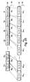
- H04N—PICTORIAL COMMUNICATION, e.g. TELEVISION
- H04N21/00—Selective content distribution, e.g. interactive television or video on demand [VOD]
- H04N21/40—Client devices specifically adapted for the reception of or interaction with content, e.g. set-top-box [STB]; Operations thereof
- H04N21/43—Processing of content or additional data, e.g. demultiplexing additional data from a digital video stream; Elementary client operations, e.g. monitoring of home network or synchronising decoder's clock; Client middleware
- H04N21/431—Generation of visual interfaces for content selection or interaction; Content or additional data rendering
- H—ELECTRICITY
- H04—ELECTRIC COMMUNICATION TECHNIQUE
- H04H—BROADCAST COMMUNICATION
- H04H20/00—Arrangements for broadcast or for distribution combined with broadcast
- H04H20/86—Arrangements characterised by the broadcast information itself
- H04H20/95—Arrangements characterised by the broadcast information itself characterised by a specific format, e.g. an encoded audio stream
- H—ELECTRICITY
- H03—ELECTRONIC CIRCUITRY
- H03M—CODING; DECODING; CODE CONVERSION IN GENERAL
- H03M13/00—Coding, decoding or code conversion, for error detection or error correction; Coding theory basic assumptions; Coding bounds; Error probability evaluation methods; Channel models; Simulation or testing of codes
- H03M13/03—Error detection or forward error correction by redundancy in data representation, i.e. code words containing more digits than the source words
- H03M13/05—Error detection or forward error correction by redundancy in data representation, i.e. code words containing more digits than the source words using block codes, i.e. a predetermined number of check bits joined to a predetermined number of information bits
- H03M13/13—Linear codes
- H03M13/15—Cyclic codes, i.e. cyclic shifts of codewords produce other codewords, e.g. codes defined by a generator polynomial, Bose-Chaudhuri-Hocquenghem [BCH] codes
- H03M13/151—Cyclic codes, i.e. cyclic shifts of codewords produce other codewords, e.g. codes defined by a generator polynomial, Bose-Chaudhuri-Hocquenghem [BCH] codes using error location or error correction polynomials
- H03M13/1515—Reed-Solomon codes
- H—ELECTRICITY
- H03—ELECTRONIC CIRCUITRY
- H03M—CODING; DECODING; CODE CONVERSION IN GENERAL
- H03M13/00—Coding, decoding or code conversion, for error detection or error correction; Coding theory basic assumptions; Coding bounds; Error probability evaluation methods; Channel models; Simulation or testing of codes
- H03M13/27—Coding, decoding or code conversion, for error detection or error correction; Coding theory basic assumptions; Coding bounds; Error probability evaluation methods; Channel models; Simulation or testing of codes using interleaving techniques
- H03M13/2703—Coding, decoding or code conversion, for error detection or error correction; Coding theory basic assumptions; Coding bounds; Error probability evaluation methods; Channel models; Simulation or testing of codes using interleaving techniques the interleaver involving at least two directions
- H03M13/2707—Simple row-column interleaver, i.e. pure block interleaving
- H—ELECTRICITY
- H03—ELECTRONIC CIRCUITRY
- H03M—CODING; DECODING; CODE CONVERSION IN GENERAL
- H03M13/00—Coding, decoding or code conversion, for error detection or error correction; Coding theory basic assumptions; Coding bounds; Error probability evaluation methods; Channel models; Simulation or testing of codes
- H03M13/35—Unequal or adaptive error protection, e.g. by providing a different level of protection according to significance of source information or by adapting the coding according to the change of transmission channel characteristics
- H03M13/356—Unequal error protection [UEP]
- H—ELECTRICITY
- H03—ELECTRONIC CIRCUITRY
- H03M—CODING; DECODING; CODE CONVERSION IN GENERAL
- H03M13/00—Coding, decoding or code conversion, for error detection or error correction; Coding theory basic assumptions; Coding bounds; Error probability evaluation methods; Channel models; Simulation or testing of codes
- H03M13/63—Joint error correction and other techniques
- H03M13/635—Error control coding in combination with rate matching
- H03M13/6362—Error control coding in combination with rate matching by puncturing
- H—ELECTRICITY
- H03—ELECTRONIC CIRCUITRY
- H03M—CODING; DECODING; CODE CONVERSION IN GENERAL
- H03M13/00—Coding, decoding or code conversion, for error detection or error correction; Coding theory basic assumptions; Coding bounds; Error probability evaluation methods; Channel models; Simulation or testing of codes
- H03M13/65—Purpose and implementation aspects
- H03M13/6522—Intended application, e.g. transmission or communication standard
- H03M13/6541—DVB-H and DVB-M
- H—ELECTRICITY
- H04—ELECTRIC COMMUNICATION TECHNIQUE
- H04L—TRANSMISSION OF DIGITAL INFORMATION, e.g. TELEGRAPHIC COMMUNICATION
- H04L1/00—Arrangements for detecting or preventing errors in the information received
- H04L1/004—Arrangements for detecting or preventing errors in the information received by using forward error control
- H04L1/0056—Systems characterized by the type of code used
- H04L1/0057—Block codes
- H—ELECTRICITY
- H04—ELECTRIC COMMUNICATION TECHNIQUE
- H04L—TRANSMISSION OF DIGITAL INFORMATION, e.g. TELEGRAPHIC COMMUNICATION
- H04L1/00—Arrangements for detecting or preventing errors in the information received
- H04L1/004—Arrangements for detecting or preventing errors in the information received by using forward error control
- H04L1/0056—Systems characterized by the type of code used
- H04L1/0067—Rate matching
- H04L1/0068—Rate matching by puncturing
- H—ELECTRICITY
- H04—ELECTRIC COMMUNICATION TECHNIQUE
- H04L—TRANSMISSION OF DIGITAL INFORMATION, e.g. TELEGRAPHIC COMMUNICATION
- H04L1/00—Arrangements for detecting or preventing errors in the information received
- H04L1/004—Arrangements for detecting or preventing errors in the information received by using forward error control
- H04L1/0056—Systems characterized by the type of code used
- H04L1/0071—Use of interleaving
- H—ELECTRICITY
- H04—ELECTRIC COMMUNICATION TECHNIQUE
- H04L—TRANSMISSION OF DIGITAL INFORMATION, e.g. TELEGRAPHIC COMMUNICATION
- H04L1/00—Arrangements for detecting or preventing errors in the information received
- H04L1/0078—Avoidance of errors by organising the transmitted data in a format specifically designed to deal with errors, e.g. location
- H04L1/0083—Formatting with frames or packets; Protocol or part of protocol for error control
- H—ELECTRICITY
- H04—ELECTRIC COMMUNICATION TECHNIQUE
- H04N—PICTORIAL COMMUNICATION, e.g. TELEVISION
- H04N21/00—Selective content distribution, e.g. interactive television or video on demand [VOD]
- H04N21/60—Network structure or processes for video distribution between server and client or between remote clients; Control signalling between clients, server and network components; Transmission of management data between server and client, e.g. sending from server to client commands for recording incoming content stream; Communication details between server and client
- H04N21/63—Control signaling related to video distribution between client, server and network components; Network processes for video distribution between server and clients or between remote clients, e.g. transmitting basic layer and enhancement layers over different transmission paths, setting up a peer-to-peer communication via Internet between remote STB's; Communication protocols; Addressing
- H04N21/643—Communication protocols
- H04N21/64315—DVB-H
- H—ELECTRICITY
- H04—ELECTRIC COMMUNICATION TECHNIQUE
- H04H—BROADCAST COMMUNICATION
- H04H60/00—Arrangements for broadcast applications with a direct linking to broadcast information or broadcast space-time; Broadcast-related systems
- H04H60/02—Arrangements for generating broadcast information; Arrangements for generating broadcast-related information with a direct linking to broadcast information or to broadcast space-time; Arrangements for simultaneous generation of broadcast information and broadcast-related information
- H04H60/07—Arrangements for generating broadcast information; Arrangements for generating broadcast-related information with a direct linking to broadcast information or to broadcast space-time; Arrangements for simultaneous generation of broadcast information and broadcast-related information characterised by processes or methods for the generation
- H—ELECTRICITY
- H04—ELECTRIC COMMUNICATION TECHNIQUE
- H04L—TRANSMISSION OF DIGITAL INFORMATION, e.g. TELEGRAPHIC COMMUNICATION
- H04L1/00—Arrangements for detecting or preventing errors in the information received
- H04L1/004—Arrangements for detecting or preventing errors in the information received by using forward error control
- H04L1/0075—Transmission of coding parameters to receiver
Landscapes
- Engineering & Computer Science (AREA)
- Physics & Mathematics (AREA)
- Signal Processing (AREA)
- Probability & Statistics with Applications (AREA)
- Theoretical Computer Science (AREA)
- Computer Networks & Wireless Communication (AREA)
- Mathematical Physics (AREA)
- Multimedia (AREA)
- Pure & Applied Mathematics (AREA)
- General Physics & Mathematics (AREA)
- Algebra (AREA)
- Detection And Prevention Of Errors In Transmission (AREA)
- Time-Division Multiplex Systems (AREA)
- Data Exchanges In Wide-Area Networks (AREA)
- Two-Way Televisions, Distribution Of Moving Picture Or The Like (AREA)
- Mobile Radio Communication Systems (AREA)
Abstract
Translated fromJapaneseDescription
Translated fromJapanese本発明は、デジタルブロードキャスティングネットワークにおいてバーストを伝送する方法に関し、詳細には、限定ではないが、デジタルビデオブロードキャスティング(DVB)ネットワークにおいてバーストを伝送する方法に関する。 The present invention relates to a method for transmitting bursts in a digital broadcasting network, and more particularly, but not exclusively, to a method for transmitting bursts in a digital video broadcasting (DVB) network.
本発明はまた、デジタルブロードキャスティングネットワークで伝送されことになるバーストを作成するためのネットワーク要素に関し、詳細には、限定ではないが、DVBネットワークで使用するマルチプロトコルエンキャプスレータ(MPE)に関する。 The present invention also relates to a network element for creating bursts to be transmitted in a digital broadcasting network, and more particularly, but not exclusively, to a multi-protocol encapsulator (MPE) for use in a DVB network.
本発明は更に、デジタルブロードキャスティングネットワークからデータを受信するための端末に関し、詳細には、限定ではないが、DVBネットワークからのデータを受信するための移動ハンドヘルド端末に関する。 The invention further relates to a terminal for receiving data from a digital broadcasting network, and in particular, without limitation, to a mobile handheld terminal for receiving data from a DVB network.
ETSI EN 302 304「デジタルビデオブロードキャスティング(DVB);ハンドヘルド端末向け伝送システム(DVB−H)」V1.1.1(2004−06)は、マルチメディアサービスをDVBネットワークを経由して移動ハンドヘルド端末に配信するためのシステムの仕様を定めている。このシステムは、ETSI EN 301 192「デジタルビデオブロードキャスティング(DVB);データブロードキャスティングのためのDVB仕様」V1.4.1(2004−06)で規定されたDVBデータブロードキャスティングに基づく。 ETSI EN 302 304 “Digital Video Broadcasting (DVB); Transmission System for Handheld Terminals (DVB-H)” V1.1.1 (2004-06) provides multimedia services to mobile handheld terminals via DVB networks. It defines the system specifications for distribution. This system is based on DVB data broadcasting specified in ETSI EN 301 192 “Digital Video Broadcasting (DVB); DVB Specification for Data Broadcasting” V1.4.1 (2004-06).
DVBデータブロードキャスティングでは、データはデータグラムで端末に配信され、データグラムはマルチプロトコル・エンキャプスレーション(MPE)を使用してセクション内に配置される。MPEセクションは、伝送のため、ISO/IEC規格13818−1「情報技術−動画及び関連する音声情報の汎用コーディング:システム」に従ってMPEG−2トランスポートストリーム(TS)パケットにマップされる。 In DVB data broadcasting, data is delivered to terminals in datagrams, and datagrams are placed in sections using multi-protocol encapsulation (MPE). The MPE section is mapped to MPEG-2 Transport Stream (TS) packets for transmission according to ISO / IEC standard 13818-1 “Information Technology—Universal Coding of Video and Associated Audio Information: System”.
バッテリー駆動の移動端末でのデータ受信は、商用電源駆動の固定端末よりも困難である。例えば移動受信は、特にインパルス雑音の影響を受けやすい。更に、端末のバッテリーパワーは限られている。 Data reception at a battery-powered mobile terminal is more difficult than a commercial power-powered fixed terminal. For example, mobile reception is particularly susceptible to impulse noise. Furthermore, the battery power of the terminal is limited.
DVB−Hは、順方向誤り訂正(FEC)を利用して雑音に対するロバスト性を与え、タイムスライシングを使用して端末がバッテリー寿命を節約することができるようにする。 DVB-H uses forward error correction (FEC) to provide robustness against noise and use time slicing to allow the terminal to save battery life.
データ及び関連するFECパリティデータは、MPE−FECフレームとして公知のデータフレームで作成することができ、EN 302 304同書の節9.3を参照されたい。 Data and associated FEC parity data can be created in data frames known as MPE-FEC frames, see Section 9.3 of EN 302 304.
従来のMPE−FECフレームは、255の列とフレキシブルな数の行とを有するマトリックスとして配列される。行の数は、サービス情報(SI)において信号が送られ、最大1024の値を有することができる。マトリックスの各ポジションは1バイトのデータを保持しているので、MPE−FECフレームは、最大でほぼ2メガビットのデータを保持することができる。 A conventional MPE-FEC frame is arranged as a matrix having 255 columns and a flexible number of rows. The number of rows is signaled in the service information (SI) and can have a value of up to 1024. Since each position of the matrix holds 1-byte data, the MPE-FEC frame can hold data of approximately 2 megabits at maximum.
191の最左端列からなるMPE−FECフレームの左部分は、インターネットプロトコル(IP)データグラムなどのOSIレイヤ3(言い換えれば、ネットワークレイヤ)データグラム及び利用可能なパディングの専用に設けられており、アプリケーションデータテーブルと呼ばれる。64の最右端列からなるMPE−FECフレームの右部分は、FECコードのパリティ情報用専用であり、RSデータテーブルと呼ばれる。アプリケーションデータテーブルの各バイトポジションは、0から191×no_of_rows−1にわたるアドレスを有する。同様に、RSデータテーブルの各バイトポジションは、0から64×no_of_rows−1にわたるアドレスを有する。 The left part of the MPE-FEC frame consisting of the leftmost column of 191 is dedicated to OSI layer 3 (in other words, network layer) datagrams such as Internet Protocol (IP) datagrams and available padding, Called application data table. The right part of the MPE-FEC frame consisting of 64 rightmost columns is dedicated for parity information of the FEC code and is called an RS data table. Each byte position in the application data table has an address ranging from 0 to 191 × no_of_rows-1. Similarly, each byte position in the RS data table has an address ranging from 0 to 64 × no_of_rows−1.
レイヤ3データグラムは、データグラム毎に導入され、マトリックスの上方左コーナの第1データグラムの最初のバイトから始め、第1列を下方に進む。データグラムの長さは、データグラム毎に任意に変わる可能性がある。1つのデータグラムの終わりの直後に次のデータグラムが始まる。データグラムが列の終わりで正確に終了しない場合、データグラムは次の列のトップに続く。全データグラムがアプリケーションデータテーブルを入力すると、満たされていないあらゆるバイトポジションはゼロバイトでパッドされ、これによって最左端の191の列は完全に満たされる。
最左端の191列の全てが満たされると、各行について、191バイトのデータから64パリティバイト及び可能なパディングを計算することができる。使用されるコードは、Reed−Solomon(リード−ソロモン)RS(255,191,64)である。この場合各行は1つのRSコードワードを包含する。RSデータテーブルの最右端列の一部は廃棄することができ、従って、伝送されずにパンクチュアリングを可能にする。パンクチュアされたRS列の正確な数は明示的に信号を送る必要はなく、フレーム間で動的に変化させることができる。従って、RSデータテーブルは満たされ、MPE−FECフレームが完成する。 When all the leftmost 191 columns are filled, 64 parity bytes and possible padding can be calculated from 191 bytes of data for each row. The code used is Reed-Solomon RS (255, 191, 64). In this case, each row contains one RS code word. Part of the rightmost column of the RS data table can be discarded, thus allowing puncturing without being transmitted. The exact number of punctured RS sequences does not need to be explicitly signaled and can change dynamically between frames. Therefore, the RS data table is filled and the MPE-FEC frame is completed.
IPデータグラムはMPEセクションにマップされ、RS列はMPE−FECセクションにマップされる。 The IP datagram is mapped to the MPE section, and the RS sequence is mapped to the MPE-FEC section.
データグラムは、MPE−FECが使用されるかどうかに関係なくDVB規格に準拠してMPEセクションで搬送される。これによって、MPE−FECを知らない受信器と完全に下位互換性があるようになる。各セクションは、セクションヘッダでペイロードに対する開始アドレスを搬送する。このアドレスは、セクションペイロードの最初のバイトのアプリケーションデータテーブルでのバイトポジションを示す。データグラムが複数のMPEセクションに分割される場合、各MPEセクションは、セクション内で搬送されるデータグラムフラグメントの最初のバイトのアプリケーションデータテーブルにおけるバイトポジションを示す。次いで、セクションが正しいことをセクションCRC−32チェックが示しているときには、受信器は、受信されたデータグラムをアプリケーションデータテーブルでの正しいバイトポジションに配置し、これらのポジションをRSデコーダに対して「信頼できる」ものとしてマークすることができる。 Datagrams are carried in the MPE section according to the DVB standard regardless of whether MPE-FEC is used. This makes it fully backward compatible with receivers that do not know MPE-FEC. Each section carries the start address for the payload in the section header. This address indicates the byte position in the application data table of the first byte of the section payload. If the datagram is divided into multiple MPE sections, each MPE section indicates the byte position in the application data table of the first byte of the datagram fragment carried within the section. Then, when the section CRC-32 check indicates that the section is correct, the receiver places the received datagrams in the correct byte positions in the application data table and places these positions with respect to the RS decoder. Can be marked as "trusted".
アプリケーションデータテーブルの最後のセクションは、アプリケーションデータテーブル内のデータグラムの終わりを示すテーブル境界フラグを包含する。アプリケーションデータテーブル内の全ての前のセクションが正確に受信された場合、受信器は、どのMPE−FECセクションも受信する必要がなく、タイムスライシングが使用された場合、受信器は、RSデータを受信及び復号することなくスイッチオフにすることができる。また、MPE−FECセクションが受信された場合、アプリケーションデータテーブルでのパディング列の数(パディングバイトのみで満たされた列)は、MPE−FECセクションのセクションヘッダにおける8ビットで示され、この値は、RS復号が行われる場合に使用される。 The last section of the application data table contains a table boundary flag that indicates the end of the datagram in the application data table. If all previous sections in the application data table are correctly received, the receiver does not need to receive any MPE-FEC sections, and if time slicing is used, the receiver receives RS data. And can be switched off without decoding. When an MPE-FEC section is received, the number of padding columns in the application data table (a column filled with only padding bytes) is indicated by 8 bits in the section header of the MPE-FEC section, and this value is Used when RS decoding is performed.
RS列は、MPE−FECセクションで搬送される。各セクションは、RSデータテーブルの正確に1つの列を搬送する。パンクチュアされた列は伝送されず、明示的に信号を送らない。 The RS string is carried in the MPE-FEC section. Each section carries exactly one column of the RS data table. The punctured sequence is not transmitted and does not explicitly signal.
データはタイムスライシングバーストで伝送することができ、EN 302 304同書の節9.2を参照されたい。 Data can be transmitted in time slicing bursts, see Section 9.2 of EN 302 304 ibid.
タイムスライシングは、データが従来の帯域幅管理を使用して伝送された場合に必要とされるビットレートに比べて、非常に高いビットレートを使用してバーストでデータを送信することを含む。バースト内で、次のバーストの開始前の時間(デルタ−t)が示される。バースト間では、エレメンタリ・ストリームのデータは伝送されず、他のエレメンタリ・ストリームが他の割り当てられた帯域幅を使用することができるようにする。これによって、受信器は、要求されるサービスのバーストを受信する間、時間の1つのフラグメントについてのみアクティブのままでいることが可能となる。 Time slicing involves transmitting data in bursts using a very high bit rate compared to the bit rate required when the data is transmitted using conventional bandwidth management. Within a burst, the time (delta-t) before the start of the next burst is indicated. No data in the elementary stream is transmitted between bursts, allowing other elementary streams to use other allocated bandwidth. This allows the receiver to remain active for only one fragment of time while receiving the required burst of service.
従来では、1つのMPE−FECフレームのコンテンツは、1つのタイムスライスされたバーストで伝送されていた。しかしながら、この構成には少なくとも2つの欠点がある。 Conventionally, the content of one MPE-FEC frame has been transmitted in one time-sliced burst. However, this configuration has at least two drawbacks.
第1に、アプリケーションデータとRSデータのインターリービングの長さが短いので、バーストが雑音の影響を受けやすい。1つの解決策は、バーストの持続時間を長くすることである。しかしながら、これによりタイムスライシングの利点が縮小される。 First, since the length of interleaving between application data and RS data is short, bursts are susceptible to noise. One solution is to increase the duration of the burst. However, this reduces the benefits of time slicing.
第2に、バーストが1つよりも多いサービスにデータを搬送する場合、同じレベルの誤り保護が使用される。 Second, the same level of error protection is used when carrying data to a service with more than one burst.
本発明は、デジタルブロードキャスティングネットワークでバーストを伝送する方法、デジタルブロードキャスティングネットワークでの伝送におけるバーストを作成するためのネットワーク要素、及び/又はデジタルブロードキャスティングネットワークからバーストを受信するための端末を提供することを追求している。 The present invention provides a method for transmitting a burst in a digital broadcasting network, a network element for creating a burst in transmission on a digital broadcasting network, and / or a terminal for receiving a burst from a digital broadcasting network. Pursuing that.
本発明の第1の態様によれば、デジタルブロードキャスティングネットワークでバーストを伝送する方法が提供され、該方法は、データの第1セットと順方向誤り訂正(FEC)データの対応する第1セットとを含む第1データフレームを提供する段階と、バーストのシーケンスを形成する段階と、第1データフレームをバースト間で分割する段階とを含み、データの第1セットは、少なくとも2つのバースト間で分割される。従って、データフレームのインターリービングの長さを増大させることができる。 According to a first aspect of the present invention, there is provided a method for transmitting bursts in a digital broadcasting network, the method comprising: a first set of data and a corresponding first set of forward error correction (FEC) data; Providing a first data frame including: forming a sequence of bursts; and dividing the first data frame between bursts, wherein the first set of data is divided between at least two bursts Is done. Accordingly, the length of data frame interleaving can be increased.
少なくとも1つのバーストは、FECデータを含むことができない。 At least one burst cannot contain FEC data.
本方法は、データの第2セットとFECデータの対応する第2セットとを含む第2データフレームを提供する段階と、第2データフレーム内の第2データとFECデータの第2セットとを複数のバースト間で分割する段階を更に含むことができる。本方法は、第1データフレームをデータフレームブロックの第1セットに分割する段階と、第2データフレームをデータフレームブロックの第2セットに分割する段階と、データフレームブロックの第1及び第2セットをインターリーブする段階と、インターリーブされたデータフレームブロックを複数のバーストに順次配置する段階とを含むことができる。 The method provides a second data frame including a second set of data and a corresponding second set of FEC data, and a plurality of second data in the second data frame and a second set of FEC data. The method may further include dividing between the bursts. The method includes dividing a first data frame into a first set of data frame blocks, dividing a second data frame into a second set of data frame blocks, and first and second sets of data frame blocks. And interleaving the interleaved data frame blocks into a plurality of bursts.
本発明の第2の態様によれば、デジタルブロードキャスティングネットワークでバーストを伝送する方法が提供され、本方法は、データの第1セットと順方向誤り訂正(FEC)データの対応する第1セットとを含む第1データフレームを提供する段階と、データの第2セットとFECデータの対応する第2セットとを含む第2データフレームを提供する段階と、前記第1及び第2データフレームを含むバーストを形成する段階とを含む。従って、異なるレベルの順方向誤り訂正を備えたデータの第1及び第2セットを伝送することが求められた場合、これらは同じバーストで伝送される。 According to a second aspect of the present invention, there is provided a method for transmitting bursts in a digital broadcasting network, the method comprising a first set of data and a corresponding first set of forward error correction (FEC) data; Providing a first data frame including: a second data frame including a second set of data and a corresponding second set of FEC data; and a burst including the first and second data frames. Forming. Thus, if it is desired to transmit the first and second sets of data with different levels of forward error correction, they are transmitted in the same burst.
本方法は、データの起点を識別するためのそれぞれのラベルを各データフレームに付与する段階を更に含むことができる。本方法は更に、データフレームのシーケンスにおいてデータフレームを位置付けるためのそれぞれのラベルを各データフレームに付与する段階を含むことができる。本方法は更に、バーストのシーケンス内のバーストを識別するためのそれぞれのラベルを各バーストに付与する段階を含むことができる。第1データフレームを提供する段階は、第1及び第2部分を含む第1アレイを提供する段階と、第1アレイ部分の少なくとも一部をデータの第1セットで満たす段階と、第1アレイ部分のデータに基づいてFECデータの第1セットを求める段階と、FECデータの第1セットを第2アレイ部分に配置する段階とを含むことができる。 The method can further include providing each data frame with a respective label for identifying the origin of the data. The method can further include providing each data frame with a respective label for positioning the data frame in the sequence of data frames. The method can further include providing each burst with a respective label for identifying a burst in the sequence of bursts. Providing a first data frame includes providing a first array including first and second portions, filling at least a portion of the first array portion with a first set of data, and a first array portion. Determining a first set of FEC data based on the first data and placing the first set of FEC data in the second array portion.
本方法は、データの第1セットをマルチプロトコル・エンキャプスレーション(MPE)セクションの第1セットにエンキャプスレートする段階と、対応するFECデータをMPEセクションの第2セットにエンキャプスレートする段階とを含むことができる。複数のバーストを形成する段階は、MPEセクションの第1及び第2セットを時間的にオフセットされたグループに構成する段階を含むことができる。第1データフレームは、マルチプロトコル・エンキャプスレーション順方向誤り訂正(MPE−FEC)フレームとすることができる。 The method encapsulates a first set of data into a first set of multi-protocol encapsulation (MPE) sections and encapsulates corresponding FEC data into a second set of MPE sections; Can be included. Forming the plurality of bursts may include configuring the first and second sets of MPE sections into temporally offset groups. The first data frame may be a multi-protocol encapsulation forward error correction (MPE-FEC) frame.
デジタルブロードキャスティングネットワークは、デジタルビデオブロードキャスティングネットワークとすることができる。 The digital broadcasting network may be a digital video broadcasting network.
本発明の第3の態様によれば、デジタルブロードキャスティングネットワークからバーストを受信するための端末の動作方法が提供され、本方法は、データフレームのためのデータを含む第1バーストを受信する段階と、データをデータフレーム内に配置する段階と、第1バーストを含むバーストのシーケンスにおける第2バーストが従う指標を第1バーストから抽出する段階と、データフレームのための追加データを含む第2バーストを受信する段階と、データフレームに追加データを配置する段階とを含む。 According to a third aspect of the invention, there is provided a method of operating a terminal for receiving a burst from a digital broadcasting network, the method comprising receiving a first burst including data for a data frame; Placing data in the data frame; extracting from the first burst an indication that the second burst in the sequence of bursts including the first burst follows; and a second burst including additional data for the data frame Receiving and placing additional data in the data frame.
本発明の第4の態様によれば、デジタルブロードキャスティングネットワークからバーストを受信するための端末の動作方法が提供され、本方法は、複数のデータフレームのためのデータを含むバーストを受信する段階と、データのセットと該データのセットが属するデータフレームに関する指標とをバーストからを抽出する段階と、対応するデータフレームにデータの各セットを配置する段階とを含む。 According to a fourth aspect of the invention, there is provided a method of operating a terminal for receiving a burst from a digital broadcasting network, the method comprising receiving a burst including data for a plurality of data frames; Extracting from the burst a set of data and an indication relating to the data frame to which the data set belongs, and placing each set of data in a corresponding data frame.
本発明の第5の態様によれば、データ処理装置に対して、データの第1セットと順方向誤り訂正(FEC)データの対応する第1セットとを含む第1データフレームを提供させ、バーストのシーケンスを形成させ、データの第1セットが少なくとも2つのバースト間で分割されるように第1データフレームをバースト間で分割させる命令を含むコンピュータプログラムが提供される。 According to a fifth aspect of the present invention, a data processing apparatus is provided with a first data frame including a first set of data and a corresponding first set of forward error correction (FEC) data, and a burst And a computer program comprising instructions for splitting a first data frame between bursts such that a first set of data is split between at least two bursts.
本発明の第6の態様によれば、データ処理装置に対して、データの第1セットと順方向誤り訂正(FEC)データの対応する第1セットとを含む第1データフレームを提供させ、データの第2セットとFECデータの対応する第2セットとを含む第2データフレームを提供させ、第1及び第2データフレームを含むバーストを形成させるための命令を含むコンピュータプログラムが提供される。 According to a sixth aspect of the present invention, the data processing apparatus is provided with a first data frame including a first set of data and a corresponding first set of forward error correction (FEC) data, and the data A computer program is provided that includes instructions for providing a second data frame that includes a second set of FEC data and a corresponding second set of FEC data, and forming a burst that includes the first and second data frames.
本発明の第7の態様によれば、データ処理装置に対して、データフレームのためのデータを含む第1バーストを受信させ、データフレーム内にデータを配置させ、第1バーストを含むバーストのシーケンスにおいて第2バーストが従う指標を第1バーストから抽出させ、データフレームのための追加データを含む第2バーストを受信させ、データフレーム内に追加データを配置させるための命令を含むコンピュータプログラムが提供される。 According to the seventh aspect of the present invention, the data processing apparatus is caused to receive a first burst including data for a data frame, arrange data in the data frame, and a sequence of bursts including the first burst. There is provided a computer program comprising instructions for extracting an indication followed by a second burst from the first burst, receiving a second burst including additional data for the data frame, and placing the additional data within the data frame The
本発明の第8の態様によれば、データ処理装置に対して、複数のデータフレームのためのデータを含むバーストを受信させ、データのセットと該データのセットが属するデータフレームに関する指標とをバーストから抽出させ、データのセットを対応するデータフレーム内に配置させるための命令を含むコンピュータプログラムが提供される。 According to an eighth aspect of the present invention, a data processing apparatus is caused to receive a burst including data for a plurality of data frames, and a burst of a set of data and an index relating to a data frame to which the set of data belongs is burst. A computer program is provided that includes instructions for extracting from and placing a set of data in a corresponding data frame.
コンピュータプログラムは、データキャリア上又はメモリ内に記憶することができる。 The computer program can be stored on a data carrier or in a memory.
本発明の第9の態様によれば、デジタルブロードキャスティングネットワークにおいてバーストを伝送するためのシステムが提供され、本システムは、データの第1セットと順方向誤り訂正(FEC)データの対応する第1セットとを含む第1データフレームを提供する段階と、バーストのシーケンスを形成する段階と、第1データフレームをバースト間で分割する段階とを含み、データの第1セットは少なくとも2つのバースト間で分割されることを特徴とする。 According to a ninth aspect of the present invention, there is provided a system for transmitting bursts in a digital broadcasting network, the system comprising a first set of data and a corresponding first of forward error correction (FEC) data. Providing a first data frame including a set, forming a sequence of bursts, and dividing the first data frame between bursts, wherein the first set of data is between at least two bursts. It is divided.
本発明の第10の態様によれば、デジタルブロードキャスティングネットワークにおいてバーストを伝送するためのシステムが提供され、本システムは、データの第1セットと順方向誤り訂正(FEC)データの対応する第1セットとを含む第1データフレームを提供する段階と、データの第2セットとFECデータの対応する第2セットとを含む第2データフレームを提供する段階と、第1及び第2データフレームを含むバーストを形成する段階とを含む。 According to a tenth aspect of the present invention, there is provided a system for transmitting bursts in a digital broadcasting network, the system comprising a first set of data and a corresponding first of forward error correction (FEC) data. Providing a first data frame including a set, providing a second data frame including a second set of data and a corresponding second set of FEC data, and including first and second data frames Forming a burst.
本発明の第11の態様によれば、データの第1セットと順方向誤り訂正(FEC)データの対応する第1セットとを含む第1データフレームを提供し、バーストのシーケンスを形成し、データの第1セットは少なくとも2つのバースト間で分割されるように第1データフレームをバースト間で分割するように構成されたネットワーク要素が提供される。 According to an eleventh aspect of the present invention, there is provided a first data frame comprising a first set of data and a corresponding first set of forward error correction (FEC) data, forming a sequence of bursts, and data A network element is provided that is configured to divide the first data frame between the bursts such that the first set of is divided between at least two bursts.
本発明の第12の態様によれば、データの第1セットと順方向誤り訂正(FEC)データの対応する第1セットとを含む第1データフレームを提供し、データの第2セットとFECデータの対応する第2セットとを含む第2データフレームを提供し、第1及び第2データフレームを含むバーストを形成するように構成されたネットワーク要素が提供される。 According to a twelfth aspect of the present invention, a first data frame is provided that includes a first set of data and a corresponding first set of forward error correction (FEC) data, the second set of data and the FEC data. A network element configured to provide a second data frame including a corresponding second set of data and to form a burst including the first and second data frames is provided.
ネットワーク要素は、マルチプロトコル・エンキャプスレーション(MPE)エンキャプスレータとすることができる。 The network element may be a multi-protocol encapsulation (MPE) encapsulator.
本発明の第13の態様によれば、デジタルブロードキャスティングネットワークからバーストを受信するための端末が提供され、本端末は、データフレームのためのデータを含む第1バーストを受信し、データをデータフレーム内に配置し、第1バーストを含むバーストのシーケンスにおける第2バーストが従う指標を第1バーストから抽出し、データフレームのための追加データを含む第2バーストを受信し、追加データをデータフレーム内に配置するように構成されている。 According to a thirteenth aspect of the present invention, there is provided a terminal for receiving a burst from a digital broadcasting network, wherein the terminal receives a first burst including data for a data frame and transmits the data to a data frame. The second burst in the sequence of bursts including the first burst is extracted from the first burst, the second burst including additional data for the data frame is received, and the additional data is received in the data frame It is comprised so that it may arrange.
本発明の第14の態様によれば、デジタルブロードキャスティングネットワークからバーストを受信するための端末が提供され、本端末は、複数のデータフレームのためのデータを含むバーストを受信し、データのセットと該データのセットが属するデータフレームに関する指標とを前記バーストから抽出し、データのセットを対応するデータフレーム内に配置するように構成されている。 According to a fourteenth aspect of the present invention, there is provided a terminal for receiving a burst from a digital broadcasting network, the terminal receiving a burst including data for a plurality of data frames, An index relating to the data frame to which the data set belongs is extracted from the burst, and the data set is arranged in the corresponding data frame.
本発明の実施形態を添付図面を参照しながら例証として説明する。 Embodiments of the present invention will now be described by way of example with reference to the accompanying drawings.
デジタルブロードキャスティングネットワーク1
図1を参照すると、本発明による移動端末2にコンテンツを配信するための通信ネットワーク1が示されている。通信ネットワーク1は、ハンドヘルドデジタルビデオブロードキャスティング(DVB−H)ネットワークを含み、該ネットワークは、インターネットプロトコルデータキャスティング(IPDC)サービスとしてコンテンツを配信するブロードキャストアクセスネットワークとして使用される。しかしながら、地上DVB(DVB−T)ネットワーク、ケーブルDVB(DVB−C)ネットワーク若しくは衛星DVB(DVB−S)ネットワーク、デジタル音声ブロードキャスティング(DAB)ネットワーク、米国次世代テレビシステム委員会(ATSC)ネットワーク、地上統合サービスデジタルブロードキャスティング地上(ISDB−T)ネットワーク、及びこれらのネットワークに類似した或いはこれらに基づく他のネットワークなど、DVBネットワークの他のタイプを含む他のデジタルブロードキャストネットワークを使用することができる。
Referring to FIG. 1, a
ネットワーク1は、例えばビデオ、音声、及びデータファイルの形式のコンテンツソース31、32と、コンテンツを検索し、再フォーマットし、記憶するコンテンツプロバイダ4と、サービス構成を決定するデータキャストサービスシステムサーバー5と、マルチプロトコル・エンキャプスレーション(MPE)エンキャプスレータ6と、信号8を変調して移動端末2を含む受信器(図示せず)にブロードキャストするための送信器7とを含む。The
信号8を受信し再送信するための1つ又はそれ以上のギャップフィラー送信器(図示せず)などの他のネットワーク要素を設けることもできる。更に、好ましくはそれぞれGSM又はUMTSのような第2世代又は第3世代移動体ネットワークの形式の公衆陸上移動ネットワークなどの通信ネットワーク(図示せず)を備え、移動端末2からデジタルブロードキャスティングネットワーク1への戻りチャンネルを提供することができる。インターネットなどの別の通信ネットワーク(図示せず)を備え、コンテンツプロバイダ4及びサービスシステムサーバー5などのデジタルブロードキャスティングネットワーク1の分散要素を接続することができる。 Other network elements such as one or more gap filler transmitters (not shown) for receiving and retransmitting the
MPEエンキャプスレータ6
図2を参照すると、MPEエンキャプスレータ6及び送信器7の機能ブロック図が示されている。
Referring to FIG. 2, a functional block diagram of the
MPEエンキャプスレータ6は、種々のIPアドレス及びサービス情報データ10を有する複数のインターネットプロトコル(IP)ストリーム9の形式でコンテンツを受信し、サービス情報データ10は、MPEGプログラム仕様情報(PSI)及びDVBサービス情報(SI)を作成するのに使用される。 The
MPEエンキャプスレータ6は、IP逆多重化ブロック11を含み、1つ又はそれ以上の所要のIPストリームをフィルタ処理し、フィルタ処理されたIPストリームを1つ又はそれ以上のフィルタ処理されたストリーム12に構成する。各フィルタ処理されたストリーム12は、1つ又はそれ以上のIPストリームを含むことができる。逆多重化ブロック11は、フィルタ処理されたストリーム12を符号化ブロック13に転送する。 The
MPEエンキャプスレータ6は、フィルタ処理されたストリーム12用の順方向誤り訂正(FEC)を可能にする符号化ブロック13を含む。符号化ブロック13は、MPE−FECフレーム14を作成し転送する。FECが所与のフィルタ処理されたストリーム12に対して使用されない場合、エンコーダ13は符号化を行わず、ストリーム12をバッファするだけである。エンコーダ13はまた、以下に詳細に説明されるようにインターリービングを行うことができる。 The
MPEエンキャプスレータ6は更に、MPEC−FECフレーム14に含まれるデータをMPEセクション16及びMPE−FECセクション17にマップするためのMPE/MPE−FECセクション・エンキャプスレーティングブロック15を含む。ETSI EN 301 192「デジタルビデオブロードキャスティング(DVB);データブロードキャスティングのためのDVB仕様」V1.4.1(2004−06)を参照されたい。 The
MPEエンキャプスレータ6はまた、MPEセクション16及びMPE−FECセクション17をバースト19にタイムスライスするためのタイムスライシングブロック18を含む。以下に詳細に説明されるように、MPEエンキャプスレータ6は、本発明による1つよりも多いバースト19において1つのMPE−FECフレーム14からデータを送信し、及び/又は1つのバースト19において1つよりも多いMPE−FECフレーム14からデータを送信することができる。MPEエンキャプスレータ6はまた、従来の方法で1つのバースト19において1つのMPE−FECフレーム14を送信することができるが、これはここでは詳細には説明しない。 The
MPEエンキャプスレータ6はまた、ETSI EN 300 468「デジタルビデオブロードキャスティング(DVB);DVBシステムにおけるサービス情報(SI)のための仕様」V1.6.1(2004−6)に従って、SIテーブルをセクション21にマップするためのSI/PSIセクション・エンキャプスレーティングブロック20を含む。 The
MPEエンキャプスレータ6はまた、図2に示されるエンキャプスレータの他の要素を管理するための制御ブロック22を含む。 The
MPEエンキャプスレータ6の機能は、コンピュータプログラム(図示せず)を実行するコンピュータ(図示せず)によって実装することができる。 The functions of the
送信器7は、トランスポートストリーム(TS)生成及び多重化ブロック23を含む。TS生成及び多重化ブロック23は、バースト19内に含まれるMPEセクション16及びMPE−FECセクション17をフラグメントに分割し、これをTSパケット25Aに配置(図25)して、例えばMPEG−2TVサービス24を搬送する他のパケットと共に多重化し、TSパケットをISO/IEC規格13818−1「情報技術−動画及び関連する音声情報の汎用コーディング:システム」に従ったマルチプレックス25にする。The
送信器7はまた、ETSI EN 300 744「デジタルビデオブロードキャスティング(DVB);デジタル地上テレビ(DVB−T)のためのフレーミング構造、チャンネル符号化及び変調」V1.5.1(2004−06)に従って無線周波数信号8を生成するための変調ブロック26を含む。 The
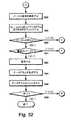
MPEエンキャプスレータ6を動作する方法
図2から18を参照し、MPEエンキャプスレータ6を動作する方法について説明する。Method for Operating MPE Encapsulator 6 A method for operating the
IPストリーム9の所与のセットにおいて、MPEエンキャプスレータ6は、本発明による1つよりも多いバースト19において1つのMPE−FECフレーム14からデータを送信し、及び/又は1つのバースト19において1つよりも多いMPE−FECフレーム14からデータを送信することができる。 In a given set of
MPEエンキャプスレータ6は、MPE−FECフレーム14を保持する複数のコーディングテーブル27を作成する(ステップS1)。これは単に、各コーディングテーブル27に対してメモリを割り当てる段階を含むことができる。以下に詳細に説明されるように、コーディングテーブル27及びMPE−FECフレーム14は、2つよりも多いメガビットのデータを保持することができる。 The
MPEエンキャプスレータ6は、タイムスライシング及びMPE−FECについての情報を信号で送り、受信器がバースト19を受信することができるようにする(ステップS2)。これは、以下に詳細に説明する。 The
図4を詳細に参照すると、デマルチプレクサ11(図2)は、第1及び第2ストリーム91、92を含む複数のストリーム9を受信する。第1ストリーム91は、データグラム281,1、281,2、281,3、281,4を含むレイヤ3データグラムの第1セット281を含む。第2ストリーム92は、データグラム282,1、282,2を含むレイヤ3データグラムの第2セット282を含む。Referring to FIG. 4 in detail, the demultiplexer 11 (FIG. 2) receives a plurality of
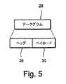
図5を参照すると、データグラムの第1及び第2セット281、282の各データグラム28は、インターネットプロトコル(IP)データグラムの形式であり、ヘッダ29とペイロード30を含む。しかしながら、UDPデータグラムなどのデータフレームの他のタイプを使用することが可能である。Referring to FIG. 5, each
ここで図6を参照すると、デマルチプレクサ11(図2)は、第1及び第2のIPストリーム91、92をフィルタ処理し、第1及び第2のフィルタ処理されたストリーム121、122にそれぞれ出力する(ステップS3)。この実施例において、各フィルタ処理されたストリーム121、122は、単一のIPストリーム91、92を含む。しかしながら、フィルタ処理されたストリーム121、122は、1つよりも多いIPストリームを含むことができる。Referring now to FIG. 6, the demultiplexer 11 (FIG. 2) filters the first and second IP streams 91 , 92 and the first and second
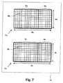
図7を参照すると、MPE−FECエンコーダ13は、第1及び第2のフィルタ処理されたストリーム121、122(図6)それぞれのための第1及び第2コーディングテーブル271、272を含む。例えば、追加のフィルタ処理されたストリーム用に、更にコーディングテーブル(図示せず)を設けることもできる。加えて、又は代替的に、同じフィルタ処理されたストリーム用に更にコーディングテーブルを設けてもよく、これらを組み合わせて単一のより大きなコーディングテーブルを形成することができる。Referring to FIG. 7, the MPE-
第1コーディングテーブル271は、アプリケーションデータテーブル321とパリティデータテーブル331を提供する。同様に、第2コーディングテーブル272は、アプリケーションデータテーブルとパリティデータテーブルを記憶するための部分322、333を提供する。The first coding table 271 provides an application data table 321 and a parity data table 331 . Similarly, the second coding table 272 provides
第1コーディングテーブル321は、255列341及びフレキシブルな数の行351を有するマトリックスとして構成することができる。行の数351は、サービス情報(SI)10(図2)において信号として送られる。コーディングテーブル271の各ポジション361は、1バイトのデータを保持する。The first coding table 321 can be configured as a matrix having 255
第2コーディングテーブル272は、255列342及びフレキシブルな数の行352を有するマトリックスとして構成することができる。行の数352は、サービス情報(SI)10(図2)において信号として送られる。コーディングテーブル272の各ポジション362は1バイトのデータを保持する。The second coding table 272 can be configured as a matrix having 255
各ポジション361、362は、ほぼ1バイトまでのデータを保持することができる。Each
第1コーディングテーブル271では、アプリケーションデータテーブル321は、コーディングテーブル271の最左端部分によって提供することができ、191列を含むことができる。アプリケーションデータテーブル321は、第1のフィルタ処理されたストリーム121(図6)及びオプションのパディングデータ(図示せず)からのデータグラム281(図6)用に確保される。パリティデータテーブル331は、第1コーディングテーブル271の最右端部分によって提供することができ、64列を含むことができる。パリティデータテーブル331は、パリティデータ用に確保される。アプリケーションデータテーブル321における各ポジションは、0から(191×no_of_rows−1)に及ぶアドレスを有する。同様に、RSデータテーブル331における各ポジションは、0から(64×no_of_rows−1)に及ぶアドレスを有する。第1コーディングテーブル271は異なるように構成することができ、異なる数の列を含むことができる。例えば、コーディングテーブル271は反転させてもよい。アプリケーションデータテーブル321は、コーディングテーブル271の最右端部分によって提供することができる。コーディングテーブル271は、コーディングテーブル271の最上位又は最下位部分によって提供されるアプリケーションデータテーブル321で横方向に分割することができる。In the first coding table 271 , the application data table 321 can be provided by the leftmost part of the coding table 271 and can include 191 columns. Application data table 321 is reserved for datagram 281 (FIG. 6) from first filtered stream 121 (FIG. 6) and optional padding data (not shown). The parity data table 331 may be provided by the rightmost part of the first coding table 271 and may include 64 columns. The parity data table 331 is reserved for parity data. Each position in the application data table 321 has an address ranging from 0 to (191 × no_of_rows−1). Similarly, each position in the RS data table 331 has an address ranging from 0 to (64 × no_of_rows−1). The first coding table 271 can be configured differently and can include a different number of columns. For example, the coding table 271 may be inverted. The application data table 321 can be provided by the rightmost part of the coding table 271 . The coding table 271 can be divided horizontally in the application data table 321 provided by the highest or lowest part of the coding table 271 .
第2コーディングテーブル272では、アプリケーションデータテーブル322は、コーディングテーブル272の最左端部分によって提供することができ、191列342を含むことができる。アプリケーションデータテーブル322は、第2のフィルタ処理されたストリーム122(図6)及びオプションのパディングデータ(図示せず)からのデータグラム282(図4c)用に確保される。パリティデータテーブル332は、コーディングテーブル272の最右端部分によって提供することができ、64列342を含むことができる。パリティデータテーブル332は、パリティデータ用に確保される。アプリケーションデータテーブル322における各ポジションは、0から(191×no_of_rows−1)に及ぶアドレスを有する。同様に、パリティデータテーブル332における各ポジションは、0から(64×no_of_rows−1)に及ぶアドレスを有する。第2コーディングテーブル272は異なるように構成することができ、異なる数の列を含むことができる。In the second coding table 272 , the application data table 322 can be provided by the leftmost part of the coding table 272 and can include 191
コーディングテーブル271、272は、異なるように構成することができる。例えば、アプリケーションデータテーブル321、322は、テーブル271、272の最右端列を含むことができる。コーディングテーブル271、272は、垂直方向ではなく横方向で上位部分と下位部分とに分割することができる。The coding tables 271 and 272 can be configured differently. For example, the application data tables 321 and 322 can include the rightmost column of the tables 271 and 272 . The coding tables 271 and 272 can be divided into an upper part and a lower part in the horizontal direction instead of the vertical direction.
第1及び第2コーディングテーブル271、272は、様々なサイズのパリティデータテーブル331、332を有することができる。言い換えると、FECコーディングの種々のレベルを使用することができる。The first and second coding tables 271 and 272 may include parity data tables 331 and 332 having various sizes. In other words, various levels of FEC coding can be used.
IPストリーム91、92は、第1及び第2コーディングテーブルに向けられる(ステップS4)。The IP streams 91 and 92 are directed to the first and second coding tables (step S4).
図8を参照すると、データグラムの第1セット281は、データグラム毎に導入され、第1コーディングテーブル271の上位左コーナにおける第1データグラム281,1の第1バイト371から始まり、第1の最左端列341,1において下方に進む。第1データグラム281,1の終わりの直後に第2データグラム281,2が始まり、その後に第3データグラム281,3、第4データグラム281,4等々が続く。Referring to FIG. 8, the
第1及び第2コーディングテーブル271,272は、異なるように満たすことができる。例えば、第1データグラム281,1の第1バイト371は、第1コーディングテーブル271の上位右コーナに配置して下方に進み、或いは下位左コーナ若しくは右コーナに配置し上方に進むことができる。The first and second coding tables 271 , 272 can be filled differently. For example, the
各データグラム281は、アプリケーションデータテーブル321のそれぞれの列341を占める。しかしながら、データグラム281は各々、1列341よりも少なく、或いは1列341よりも多く占めることができる。更に、各データグラム281の長さは、データグラム毎に変えることができる。データグラム281が列341の終わりで終了しない場合、次の列341の上部に続くことができる。データグラム281の全てがアプリケーションデータテーブル321に入力されると、満たされていないあらゆるバイトポジションはゼロバイトでパッドされ(図示せず)、従って、最左端191列を完全に満たす。しかしながらパディングは、明示的に追加される必要はない。Each
同様に、データグラムの第2セット282は、データグラム毎に導入され、第2コーディングテーブル272の上位左コーナにおける第1データグラム282,1の第1バイト372から始まり、第1最左端列342,1で下方に進む。第1データグラム282,1の終わりの直後に第2データグラム282,2が始まり、以下同様である。Similarly, a second set of
各データグラム282は、アプリケーションデータテーブル322におけるそれぞれの列342を占める。しかしながら、データグラム282は、1列342より少なく又は1列342より多くを占めることができる。更に、データグラム282の長さは、データグラム毎に変えることができる。データグラム282が列342の終わりで終了しない場合、次の列342の上部に続くことができる。全データグラム28がアプリケーションデータテーブル322を入力した場合、満たされていないあらゆるバイトポジションはゼロバイト(図示せず)でパッドされ、従って、最左端191列を完全に満たす。しかしながら、パディングは明示的に追加される必要はない。Each
ここで図9を参照すると、アプリケーションデータテーブル321は、データグラム281,1、281,2、281,3、281,4、281,r-1、281,r、281,r+1、281,n-1、281,nを含むデータグラム281で満たされる。上述のように、場合によってはアプリケーションデータテーブル321は、データグラム281で部分的に満たされるだけであり、パディングデータを付加してこれを満たすことができる。Referring now to FIG. 9, the application data table 321 includes
アプリケーションデータテーブル321が満たされると、パリティコードワード381,1、381,2、381,pを含むパリティコードワードのセット381の形式のパリティデータ381が計算され、パリティデータテーブル331に配置される(ステップS5)。従って、最後のパリティコードワード381,pが最後の行351,pに対して計算されるまで、第1パリティコードワード381,1が第1行351,1に対して計算され、第2パリティコードワード381,2が第2行351,2に対して計算され、以下同様である。When the application data table 321 is satisfied,
同様に、第2アプリケーションデータテーブル322は、データグラム282,1、282,2、282,3、282,4、282,5、282,s-1、282,s、282,s+1、282,m-1、282,mを含むデータグラム282で満たされる。Similarly, the second application data table 322 includes
第2アプリケーションデータテーブル322が満たされると、パリティコードワード382,1、382,2、382,qを含むパリティコードワード382の形式のパリティデータ382が計算され、パリティデータテーブル332に配置される。When the second application data table 322 is filled,
リード−ソロモン(RS)パリティコード、すなわち、この実施例ではRS(255,191,64)コードが使用される。従って、パリティデータテーブル331、332は、以下でRSパリティデータテーブルと呼び、パリティコードワード381、382は、以下でRSコードワードと呼ぶ。RSデータテーブル331、332の列の幾つかは廃棄することができ、従って送信されず、パンクチュアリングを可能にする。パンクチュアされたRS列の正確な数は、明示的に信号で送る必要はなく、フレーム間で動的に変化させることができる。しかしながら他のコードを使用してもよい。A Reed-Solomon (RS) parity code is used, i.e., the RS (255, 191, 64) code in this embodiment. Accordingly, the parity data tables 331 and 332 are hereinafter referred to as RS parity data tables, and the
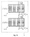
図10を参照すると、本明細書でMPE−FECフレーム141,1、142,1と呼ばれるデータのそれぞれのフレームを保持する完成された第1及び第2コーディングテーブル271、272が示されている。Referring to FIG. 10, there are shown completed first and second coding tables 271 , 272 holding respective frames of data referred to herein as MPE-FEC frames 141,1, 142,1. Has been.
第1RSデータテーブル331は、列別に分割され、RS列401,1、401,2、401,u-2、401,u-1、401,uを含むRS列データ401を提供する。同様に、第2RSデータテーブル332は、列別に分割され、RS列402,1、402,2、402,v-2、402,v-1、402,vを含むRS列データ402を提供する。The first RS data table 331 is divided by column and includes
一連のMPE−FECフレーム141,1、141,2、142,1、142,1(図19)が、各フィルタ処理されたストリーム121、122に対して生成される。各フレーム141,1、141,2、142,1、142,1を識別するために、フレーム141,1、141,2、142,1、142,1(図19)は、フレームアイデンティティパラメータFrame_idを使用して示されるフィルタ処理されたストリーム121、122に従って、及びフレームカウンタパラメータFrame_counterを使用して示されるフレームのシリーズ内のポジションに従ってラベル付けされる。A series of MPE-FEC frames 141,1 , 141,2 , 142,1 , 142,1 (FIG. 19) is generated for each filtered
従って、フレームアイデンティティ及びフレームカウンタパラメータ411,1、421,1、412,1、422,1は、各フレーム141,1、142,1に対して生成される。この実施例では、第1MPE−FECフレーム141,1に対してFrame_id=1及びFrame_counter=1、第2MPE−FECフレーム142,1に対してFrame_id=2及びFrame_counter=iである。Accordingly, frame identity and
上述のように、MPEエンキャプスレータ6は、本発明による1つよりも多いバースト19において1つのMPE−FECフレーム14からデータを送信し、及び/又は1つのバースト19において1つよりも多いMPE−FECフレーム14からデータを送信することができる。MPEエンキャプスレータ6はまた、従来の方法で1つのバースト19において1つのMPE−FECフレーム14を送信することができるが、これについては説明しない。 As described above, the
この場合、各MPE−FECフレーム141,1、142,1は、1つよりも多いバースト191、192、193において送信される(図19)。In this case, each MPE-
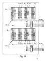
図11を参照すると、データグラム281、282は、コーディングテーブル271、272から読み出される。Referring to FIG. 11,
各データグラム281又はRS列401が第1コーディングテーブル271から読み出されるときに、エンコーダ13はまた、データグラム281の第1バイトのアドレス431、データグラム281又はRS列401がフレーム141,1の最後であるかどうかを示すテーブル境界フラグ441、及びフレーム境界フラグ451を出力することができる。As each datagram 281 or
同様に、各データグラム282又はRS列402が第2コーディングテーブル272から読み出されるときに、エンコーダ13はまた、データグラム282又はRS列402の第1バイトのアドレス432、データグラム281又はRS列402がフレーム142,1の最後であるかどうかを示すためのテーブル境界フラグ442、及びフレーム境界フラグ452を出力することができる。Similarly, when each datagram 282 or
データグラム281、282及びRS列401、402は、インターリーブされる(ステップS6及びS7)。The
r−1番目のデータグラム281,r-1が読み出されるまで、第1データグラム281,1は第1コーディングテーブル271から読み出され、データグラムは第1コーディングテーブル271から順次読み出される。次に、s−1番目のデータグラム281,s-1が読み出されるまで、第1データグラム282,1は第2コーディングテーブル272から読み出され、データグラムは第2コーディングテーブル272から順次読み出される。The
n番目のデータグラム281,nが読み出されるまで、r番目のデータグラム281,rは第1コーディングテーブル271から読み出され、データグラムは、第1コーディングテーブル271から順次読み出される。次に、m番目のデータグラム282,mが読み出されるまで、s番目のデータグラム282,sは第2コーディングテーブル272から読み出され、データグラムは第2コーディングテーブル272から順次読み出される。through
u番目のRS列401,uが読み出されるまで、第1RS列401,1は、第1コーディングテーブル271から読み出され、RS列は第1コーディングテーブル271から順次読み出される。次に、v番目のRS列402,vが読み出されるまで、第1RS列402,1は第2コーディングテーブル272から読み出され、RS列は第2コーディングテーブル272から順次読み出される。Until the
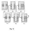
図12を参照すると、上記に説明された順序でコーディングテーブル271、272からデータグラム281、282及びRS列401、402を選択的に読み出す効果は、各MPE−FECフレーム141,1、142,1を3つのフレームブロック141,1,1、141,1,2、141,1,3、142,1,1、142,1,2、142,1,3に分割し、フレームブロック141,1,1、141,1,2、141,1,3、142,1,1、142,1,2、142,1,3をインターリーブすることである。フレームブロック141,1,1、141,1,2、141,1,3、142,1,1、142,1,2、142,1,3は、サイズが同じではない。しかしながら、MPE−FECフレーム141,1、142,1は各々、可能な限り同じサイズか或いは同じサイズに近いフレームブロックに分割することができる。MPE−FECフレーム141,1、142,1は、より少ないか又はより多いブロック141,1,1、141,1,2、141,1,3、142,1,1、142,1,2、142,1,3に分割することができ、或いは全く分割されなくともよい。更に、フレームブロック141,1,1、141,1,2、141,1,3、142,1,1、142,1,2、142,1,3は、異なる順序でインターリーブすることができる。更に、フレームブロック141,1,1、141,1,2、141,1,3、142,1,1、142,1,2、142,1,3は、他のフレームからの他のフレームブロック(図示せず)でインターリーブすることができ、その少なくとも一部は、同じフィルタ処理されたストリーム121、122から生じることができる。Referring to FIG. 12, the effect of selectively reading the
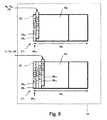
図13及び14を参照すると、フレームブロック141,1,1、141,1,2、141,1,3、142,1,1、142,1,2、142,1,3(図12)に含まれるデータグラム28及びRS列40は、これらが属するフレーム141,1、142,1(図11)及びそれぞれのアドレスデータ43用のそれぞれのフレームアイデンティティ及びフレームカウンタパラメータ41、42、テーブル境界フラグ44、及びバースト境界フラグ45と共に、MPE/MPE−FECセクション・エンキャプスレーティングブロック15に供給される。Referring to FIGS. 13 and 14, the
図13を詳細に参照すると、MPE/MPE−FECセクション・エンキャプスレーティングブロック15は、MPEセクション16を生成して出力し、各MPEセクション16はヘッダ46、ペイロード47、及びトレーラ48を含む(ステップS8)。 Referring to FIG. 13 in detail, the MPE / MPE-FEC section encapsulating
MPE/MPE−FECセクション・エンキャプスレーティングブロック15がデータグラム28を受信すると、データグラム28をペイロード47にマップし、対応するフレームアイデンティティ及びフレームカウンタパラメータ41、42をヘッダ46内に配置する(ステップS9)。MPE/MPE−FECセクション・エンキャプスレーティングブロック15はまた、アドレスデータ43、テーブル境界フラグ44、及びフレーム境界フラグ45をヘッダ46内に配置することができる(ステップS10)。MPE/MPE−FECセクション・エンキャプスレーティングブロック15は、1つよりも多いデータグラム28をペイロード47にマップすることができる。 When the MPE / MPE-FEC section encapsulating
図14を参照すると、MPE/MPE−FECセクション・エンキャプスレーティングブロック15はまた、MPE−FECセクション17を生成して出力し、各MPE−FECセクション17は、ヘッダ49、ペイロード50、及びトレーラ51を含む。 Referring to FIG. 14, the MPE / MPE-FEC section encapsulating
MPE/MPE−FECセクション・エンキャプスレーティングブロック15がRS列40を受信すると、RS列40をMPE−FECセクション17のペイロード50にマップし、対応するフレームアイデンティティ及びフレームカウンタパラメータ41、42をヘッダ49内に配置する。MPE/MPE−FECセクション・エンキャプスレーティングブロック15はまた、アドレスデータ43、テーブル境界フラグ44、及びフレーム境界フラグ45をヘッダ49に配置することができる。 When the MPE / MPE-FEC section encapsulating
MPE及びMPE−FECセクション16、17は、以下の表1に示されるデジタル記憶媒体コマンド及び制御(DSM−CC)セクションフォーマットに準拠している。
表1
Table 1
図15を参照すると、MPEセクション16において5番目のMACアドレスフィールドを分割し、フレームアイデンティティとフレームカウンタパラメータ41、42をそれぞれ記憶するための第1及び第2フィールド52、53を提供することができる。第1及び第2フィールド52、53は各々、4ビット含むことができる。第1、第2、第3、及び第4MACアドレスフィールドは、リアルタイムパラメータフィールド54を提供するのに使用される。確保されたフィールドは、3又は4ビット含むことができるバースト番号63(図18)を記憶するための第3及び第4フィールド55、56を提供するのに使用される。バースト番号は、以下に詳細に説明する。第1、第2、第3、及び第4フィールド52、53、55、56は、より小さな値又はより大きな値の使用を可能にするために異なるように配分することができる。異なるヘッダ構造が使用される場合、或いは更なるビットが利用可能になる場合、フレームアイデンティティ、フレームカウンタ、及びバースト番号41、42、63のより大きな値を使用することができる。 Referring to FIG. 15, the fifth MAC address field can be divided in the
図16を参照すると、MPE−FECセクション17において、第5MACアドレスフィールドを分割し、フレームアイデンティティ及びフレームカウンタパラメータ41、42をそれぞれ記憶するための第1及び第2フィールド57、58を提供することができる。第1及び第2フィールド57、58は各々、4ビット含むことができる。第1、第2、第3、及び第4MACアドレスフィールドは、リアルタイムパラメータフィールド59を提供するのに使用される。確保されたフィールドは、3又は4ビット含むことができるバースト番号63(図18)を記憶するための第3及び第4フィールド60、61を提供するのに使用される。第1、第2、第3、及び第4フィールド57、58、60、61は、より小さな値又はより大きな値の使用を可能にするために異なるように配分することができる。異なるヘッダ構造が使用される場合、或いは更なるビットが利用可能になる場合、フレームアイデンティティ、フレームカウンタ、及びバースト番号41、42、63のより大きな値を使用することができる。 Referring to FIG. 16, in the MPE-
リアルタイムパラメータフィールド54、59は、以下の表2に示されるシンタックスに準拠している。
表2
Table 2
バースト境界フィールドburst_boundaryは、バーストの終わりを示すのに使用され、バースト境界フラグ45を受け取る(図13)。フレーム境界フラグ45は、同じバーストにおいて種々のフレームを示すのに使用することができる。 The burst boundary field burst_boundary is used to indicate the end of the burst and receives the burst boundary flag 45 (FIG. 13). The
図17を参照すると、MPE/MPE−FECセクション・エンキャプスレーティングブロック15は、161、162、163、164、16a-1、16a、16a+1、16a+2、16a+3、16b-1、16b、16b+1、16c-2、16c-1、16c、16c+1、16d-2、16d-1を含むMPEセクション16と、171、172、17e-3、17e-2、17e-1、17e、17e+1、17f-3、17f-2、17f-1を含むMPE−FECセクション17とを出力する。Referring to FIG. 17, the MPE / MPE-FEC section encapsulating
MPEセクション16及びMPE−FECセクション17は、上述の順序でインターリーブされたデータグラム281,1、281,2、281,3、281,4、281,r-1、281,r、281,r+1、281,n-1、281,n、データグラム282,1、282,2、282,3、282,4、282,s-1、282,s、282,s+1、282,m-1、282,m、RS列401,1、401,2、401,u-2、401,u-1、401,u、及びRS列402,1、402,2、402,v-2、402,v-1、402,vを含む。しかしながら、MPEセクション16及びMPE−FECセクション17は、他の異なる順序でインターリーブさせることができる。The
データグラム28は、MPE−FECが使用されるかどうかに関わらずMPEセクション16において搬送される。これは、受信をMPE−FECに対して利用可能でない受信器(図示せず)と完全に下位互換性のあるものにする。上記のように、各MPEセクション16は、セクションヘッダ46(図13)においてペイロード47(図13)のための開始アドレス43(図13)を搬送する。このアドレス43(図13)は、セクションペイロード47(図13)の第1バイトのアプリケーションデータテーブルでのバイトポジションを示す。データグラム28が複数のMPEセクション16にわたり分割される場合、各MPEセクション16は、セクション内で搬送されるデータグラムのフラグメントの第1バイトのアプリケーションデータテーブルにおけるバイトポジションを示す。受信器(図示せず)は、アプリケーションデータテーブルでの正しいバイトポジションに受信されたデータグラム28を置き、セクションが正確であることをセクションCRC−32チェックが示した場合、RSデコーダにとって「信頼できる」ものとしてこれらのポジションをマーク付けする。
アプリケーションデータテーブルの最後のセクションは、アプリケーションデータテーブル内のデータグラムの終わりを示すテーブル境界フラグを包含する。アプリケーションデータテーブル内の前のセクション全てが正確に受信された場合、受信器は、これ以上MPE−FECセクションを受信する必要はなく、タイムスライシングが使用される場合、受信器は、RSデータを受信及び復号することなくスイッチをオフすることができる。また、MPE−FECセクション17が受信される場合、アプリケーションデータテーブルにおけるパディング列すなわちパディングバイトのみで満たされた列の数は、MPE−FECセクションのセクションヘッダにおける8バイトで示される。この値は、RS復号が実行される場合にのみ必要とされる。table_boundaryを搬送するセクションが失われた場合、受信器(図示せず)は、アプリケーションデータが終了しパディングが始まる正確なポジションを知らない可能性がある。しかしながら受信器は、パディング列から幾つの完全な列がパディングされているのかをを認識し、これらを信頼できるものとしてマーク付けすることができる。 The last section of the application data table contains a table boundary flag that indicates the end of the datagram in the application data table. If all previous sections in the application data table are correctly received, the receiver does not need to receive any more MPE-FEC sections, and if time slicing is used, the receiver receives RS data. And the switch can be turned off without decoding. When the MPE-
RS列は、MPE−FECセクション17で搬送される。各MPE−FECセクション17は、RSデータテーブルの正確に1つの列を搬送するが、これらは、1よりも少ない列又は1よりも多い列を搬送することができる。パンクチュアされた列は送信されず、パンクチュアされた列の数は明示的に信号で送られることはないが、MPE−FECセクションヘッダにおける最後のセクション番号が信号で送られる。 The RS string is carried in the MPE-
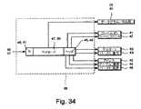
図18を参照すると、タイムスライシングモジュール18は、MPEセクション16及びMPE−FECセクション17を受信し、各セクション16、17用のデルタt62とバースト番号63の対応する値をセクション16、17のヘッダ46、49に配置する(ステップS11及びS12)。タイムスライシングモジュール18はまた、各セクション16、17に対する巡回冗長コード(CRC−32)データ64を計算し、CRC−32データ64をセクション16、17のトレーラ48、51に配置する。 Referring to FIG. 18, the
MPEセクション16及びMPE−FECセクション17は、バッファ65に転送される。同じバースト番号63を有するセクション16、17は、バースト19におけるのと同様に収集されて送信器7(図2)に転送される(ステップS13)。 The
図19を参照すると、第1及び第4フレームブロック141,1,1、142,1,1において搬送され、MPEセクション161、162、163、164、16a-1、16a、16a+1、16a+2、16a+3、16b-1(図17)を含むMPEセクション16は、第1バースト191に構成される。第2及び第5フレームブロック141,1,2、142,1,2で搬送され、MPEセクション16b、16b+1、16c-2、16c-1、16c、16c+1、16d-2、16d-1(図17)を含むMPEセクション16は、第2バースト192に構成される。第3及び第6フレームブロック141,1,3、142,1,3で搬送され、MPE−FECセクション171、172、17e-3、17e-2、17e-1、17e、17e+1、17f-3、17f-2、17f-1(図17)を含むMPE−FECセクション17は、第3バースト193に構成される。バースト191、192、193は各々、ビットレートBbで送信され、バースト持続時間Bdを有する。Referring to FIG. 19, the
各バースト19の最後のセクションは、バースト境界フラグ45(図13)を使用するなどで識別される。例えば、セクション16b-1におけるバースト境界フラグ45(図13)は「1」に設定される。受信器(図示せず)は、バースト境界フラグ45(図13)を使用してバーストを受信した時点、従って「スリープ」しなければならない時点を判定することができる。The last section of each burst 19 is identified, such as using a burst boundary flag 45 (FIG. 13). For example, the burst boundary flag 45 (FIG. 13) in the
各セクション16、17は、セクション16、17の送信時間から次のバースト19における第1セクション16、17の送信時間までの持続時間の値を搬送する。例えば、MPEセクション16bが送信されるまでの持続時間を示す第1MPEセクション16aのデルタ−t621,1が例証される。受信器(図示せず)は、デルタ−tパラメータ62(図18)を使用して「起動」すべき時間を求め、次のバースト19を受信することができる。Each
バースト番号パラメータ63(図18)の同じ値は、同じバースト19内のセクション16、17において使用される。この実施例では、バーストは、逆に数えて番号付けされ、値2で始まりゼロで終わる。受信器(図示せず)は、バースト番号パラメータ63(図18)を使用して、バースト19が失われたかどうか、或いは受信器が所与のMPE−FECフレーム14に対してバーストの全てを受信したかどうかを判定することができる。 The same value of the burst number parameter 63 (FIG. 18) is used in
バースト番号パラメータ63に対して3ビットが使用される場合、バーストは、最大15までのバースト番号で始めることができる。4ビットが、例えばMPEセクション16において確保されたフィールド55、56(図15)又はMPE−FECセクション17における確保されたフィールド60、61(図16)によって提供される構成単位である場合、バーストは最大31までのバースト番号で始めることができる。バースト番号は、ゼロに達した後で再度15から(又は31から)始まる巡回とすることができる。 If 3 bits are used for the
MPE−FECフレームを作成し送信するプロセスは、第1及び第2コーディングテーブル271、272を使用して作成された第3及び第4MPE−FECフレーム141,2、142,2の作成及び送信を続け、該第4MPE−FECフレームは、フィルタ処理されたストリーム121、122におけるデータグラム281、282が送信完了する(ステップS15)まで、第4、第5、及び第6バースト194、195、196で送信される(ステップS14)。The process of creating and transmitting the MPE-FEC frame is the creation of the third and fourth MPE-FEC frames 141,2 , 142,2 created using the first and second coding tables 271 , 272. and continues to send, said 4MPE-FEC frames, datagrams 281 in
ここで説明された実施例では、第1及び第2MPE−FECフレーム141,1、142,1は各々、3つのブロック141,1,1、141,1,2、141,1,3、142,1,1、142,1,2、142,1,3に分割された。しかしながら、MPE−FECフレーム141,1、142,1は、より少ない又はより多いブロックに分割することができる。ブロックは、同じサイズ又は同じではないサイズにすることができる。In the embodiment described here, the first and second MPE-FEC frames 141,1 , 142,1 are respectively divided into three
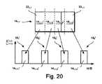
図20を参照すると、第1MPE−FECフレーム141は、4つのブロック141,1,1’、141,1,2’、141,1,3’、141,1,4’に分割し、4つのバースト191’、192’、193’、194’で送信することができる。同様に、第2MPE−FECフレーム141(図19)は、4つのブロック(図示せず)に分割することができる。更に、ブロック141,1,3’は、アプリケーションデータテーブル321,1とRSデータテーブル331,2の両方からデータを搬送することができ、言い換えるとMPEセクション16とMPE−FECセクション17を搬送する。Referring to FIG. 20, the first MPE-
1つよりも多いバースト間に1つのMPE−FECフレームからデータを分配する利点は、フレームに対するインターリービングの長さが増大する点である。バーストに影響を与える雑音の「ショット」が存在する場合、1つのMPE−FECフレームからデータの全てを失う可能性が低減される。雑音のショットから生じるデータのあらゆる誤りは、FECパリティデータを使用して訂正することができる。 An advantage of distributing data from one MPE-FEC frame between more than one burst is that the length of interleaving for the frame is increased. If there are noise “shots” that affect the burst, the likelihood of losing all of the data from one MPE-FEC frame is reduced. Any error in the data resulting from the noise shot can be corrected using the FEC parity data.
付加的に或いは代替として、以下に詳細に説明するようにより大きなMPE−FECフレーム14を使用して、複数のバースト19間の1つのMPE−GECフレーム14からのデータの分配の助けとすることができる。 Additionally or alternatively, a larger MPE-
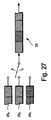
図21を参照すると、MPE−FECフレームを送信するための従来の構成が示されている。従来の構成では、各々が1024の行を有する6つのMPE−FECフレーム661,1、661,2、661,3、661,4、661,5、661,6が、それぞれのバースト671、672、673、674、675、676で送信される。この構成の欠点は、短いインターリービング深さ68を有することである。上述のように、雑音のショットがバーストの1つ、例えば第2バースト672に影響を与える場合には、この実施例では第2MPE−FECフレーム661,2であるMPE−FECフレームに含まれるデータの全てが失われる可能性がある。Referring to FIG. 21, a conventional configuration for transmitting an MPE-FEC frame is shown. In the conventional configuration, six MPE-FEC frames 661,1 , 661,2 , 661,3 , 661,4 , 661,5 , 661,6 each having 1024 rows are respectively burst 671, 672, 673, 674, 675, 67 are transmitted in6. The disadvantage of this configuration is that it has a
図22を参照すると、本発明によるMPE−FECフレームを送信するための例示的な構成が示されている。この実施例では、MPE−FECフレーム141,1’は6×1024行を有する。従って、フレーム141,1’は、12メガビットのデータを保持することができる。MPE−FECフレームは、N×M行を有することができ、ここでN=2、3、4、又は5、M=1024である。Nは6よりも大きな値を有することができる。更に、Mは1024に等しくなくてよい。例えばMは、64、128、192、256、320、384、448、512、576、640、704、768、832、896、又は960に等しいものとすることができる。MPE−FECフレーム141,1’は、列別に6つのブロック141,1,1”、141,1,2”、141,1,3”、141,1,4”、141,1,5”、141,1,6”に分割され、これらは6つのそれぞれのバースト191”、192”、193”、194”、195”、196”で送信される。各バースト191”、192”、193”、194”、195”、196”は、2メガビットのデータを含む。この構成は、インターリービング深さ68’を有する。従って、雑音のショットが、バーストの1つ、例えば第2バースト192’に影響を与える場合、データは、FECを使用して回復される可能性が高い。以下に詳細に説明するように、MPE−FECフレーム141,1’などのより大きなMPE−FECフレームを受信できるようにするために、移動端末(図示せず)は、より大きなタイムスライシングバッファ106(図31)を含むことができる。Referring to FIG. 22, an exemplary configuration for transmitting an MPE-FEC frame according to the present invention is shown. In this example, the MPE-
従って、MPE−FECフレームのサイズを大きくし、及び/又は複数のMPE−FECフレームからのデータをインターリービングすることによって、インターリービング長を増大させ雑音に対して堅牢性を与える助けとなる。 Therefore, increasing the size of the MPE-FEC frame and / or interleaving data from multiple MPE-FEC frames helps increase the interleaving length and provide robustness against noise.
上述の実施例では、2つのIPストリーム91、92(図6)からのデータグラム281、282(図6)は、バースト191、192、193(図19)の1つのセットで送信される。コーディングの同じレベルが、各IPストリーム91、92(図6)に対して使用される。言い換えると、アプリケーションデータテーブル321、322(図7)は各々同じサイズを有し、RSデータテーブル331、332(図7)は各々同じサイズを有する。In the embodiment described above, datagrams 281 , 282 (FIG. 6) fromtwo
しかしながら、異なるIPストリーム9は、異なるコーディングレート、すなわち異なるレベルのコーディングを必要とする可能性がある。IPストリーム9は種々の優先順位によって分配することが必要になる場合があることから、これが発生する可能性がある。コーディングの異なるレベルに符号化されたIPストリームは、受信器で復号するために異なる時間量と処理能力を必要とする。 However,
図23を参照すると、エンコーダ13は、各々がそれぞれのIPストリーム93、94、95を含む、第3、第4、及び第5のフィルタ処理されたストリーム123、124、125のための第3、第4、及び第5コーディングテーブル273、274、275をそれぞれ提供することができる。コーディングテーブル273、274、275は、それぞれのアプリケーションデータテーブル323、324、325とRSデータテーブル333、334、335を含む。Referring to FIG. 23, the
例えば、ビデオデータは第3IPストリーム93で送信され、音声データは第4IPストリーム94で送信され、関連のデータは第5IPストリーム95で送信される。ビデオデータは低い優先順位、関連データは高い優先順位、及び音声データは中間の優先順位で送信することが望ましい。For example, video data is transmitted at the
種々の優先順位を達成するために、異なるコーディングレベルが使用される。 Different coding levels are used to achieve different priorities.
例えば、第3コーディングテーブル273はRS(255,239,16)コードを使用し、第4コーディングテーブル274はRS(255,223,32)を使用し、第5コーディングテーブル275はRS(255,191,64)を使用する。従って、第3アプリケーションデータテーブル323は255列343のうちの239を含み、第4アプリケーションデータテーブル324は255列344のうちの223を含み、第5アプリケーションデータテーブル325は255列345のうちの223を含む。種々のコードを使用する代わりに、コーディングレートは幾つかのRS列をパンクチュアすることによって低下させることができ、アプリケーションデータテーブルにおいてパディングを使用することによって増大させることができる。For example, the third coding table 273 uses RS (255, 239, 16) code, the fourth coding table 274 uses RS (255, 223, 32), and the fifth coding table 275 uses RS ( 255, 191, 64). Therefore, the third application data table 323 includes 239 of the 255 columns 343, a fourth application data table 324 comprises 223 of 255
この実施例において、第3及び第4コーディングテーブル273、274は各々、384行343、344を含み、第5コーディングテーブル275は256行344を含む。従って、3つのMPE−FECフレーム143,1、144,1、145,1は、単一の2メガビットバースト197で送信することができる。In this embodiment, the third and fourth coding tables 273 and 274 each include 384
コーディングテーブル273、274、275は各々、より少ないか若しくはより多い列353、354、355及び/又はより少ないか若しくはより多い行343、344、345を有することができる。より大きな又はより小さなサイズのバースト197を使用することができる。しかしながら、コーディングテーブル273、274、275が記憶できるデータの量がバースト197のサイズ以下とすべき点を理解されたい。2メガビットよりも大きなバーストを使用することができる。Coding tables 273 , 274 , 275 may each have fewer or
コーディングテーブル273、274、275は、上述のものと類似の方法で計算されたデータグラム283、284、285及びRS列403、404、405で満たされ、MPE−FECフレーム143,1、144,1、145,1を生成する(ステップS3からS5)。Coding tables 273 , 274 , 275 are filled with
MPE−FECフレーム143,1、144,1、145,1は、上述のものと類似の方法で作成されたコーディングテーブル273、274、275及びバースト197から読み出される。しかしながら、インターリービングを使用する必要はない(ステップS6及びS7)。MPE-
データグラム283、284、285及びRS列403、404、405は、エンキャプスレートされる(ステップS8)。フレームアイデンティティ及びフレームカウンタパラメータ41、42(図13)は、MPEセクション16h及びMPE−FECセクション17iのヘッダに付加される(ステップS9及びS10)。The
タイムスライシングブロック19(図2)では、デルタ−t及びバーストパラメータ62、63は、MPEセクション16h及びMPE−FECセクション17iのヘッダに付加され(ステップS11及び12)、MPEセクション16h及びMPE−FECセクション17iは、単一のバースト197に構成される(ステップS13)。この場合、バースト番号パラメータ63(図18)はburst_no=0に設定することができる。デルタ−tは、次のバースト198の到達を示すために設定され、これは、コーディングテーブル273、274、275を使用して作成されたMPE−FECフレームの次のセット(図示せず)を含むことができる。In time slicing block 19 (FIG. 2), delta -t and burst
2、3、又はそれよりも多いMPE−FECフレーム14は、1つのバースト19で送信することができ、MPE−FECフレームの少なくとも1つは、他のMPE−FECフレームとは異なるコーディングレートを有することができる点を理解されたい。 Two, three, or more MPE-FEC frames 14 can be transmitted in one
図24及び図25から図27を参照し、送信器の動作方法を次に説明する。 With reference to FIGS. 24 and 25 to 27, the operation method of the transmitter will be described next.
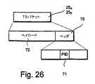
図25を詳細に参照すると、MPEセクション161、162、163、164を含むMPEセクション16とMPE−FECセクション17f-2、17f-1を含むMPE−FECセクション17との間欠的ストリームの形式におけるバースト19(図18)は、TSストリーム生成及び多重化ブロック23(図2)によって受信され、フラグメント691、692、693、694、69g-1、69gを含むセクションフラグメントに分割される。各フラグメント69は対応するTSパケット25Aに配置される。例えば、フラグメント691、692、693、694、69g-1、69gは、TSパケット25A,1、25A,2、25A,3、25A,4、25A,g-1、25A,gにそれぞれ配置される。Referring to FIG. 25 in detail, the
図26を参照すると、TSパケット25Aは通常、188バイトの長さであり、ISO/IEC規格13818−1「情報技術−動画及び関連音声情報の汎用コーディング:システム」に準拠している。各TSパケット25Aは、パケット識別子(PID)71を用いたパケットヘッダ70を含む。パケット識別子70を用いて、TSパケットペイロード72のコンテンツを識別することができる。Referring to FIG. 26, the
TSストリーム生成及び多重化ブロック23(図2)は、同じフィルタ処理されたストリーム12又はフィルタ処理されたストリーム12のセット(図2)用のMPEセクション16及びMPE−FECセクション17を搬送するバーストのセットに応じてPIDを付加する。 The TS stream generation and multiplexing block 23 (FIG. 2) is for bursts carrying
図27を参照すると、TSストリーム生成及び多重化ブロック23(図2)は、MPEセクション16及びMPE−FECセクション17を搬送するTSパケット25AをSI及びPSIテーブルセクション22(図2)を搬送するTSパケット25Bと1つ又はそれ以上のMPEG−2TVサービス24(図2)を搬送するTSパケット25Cと共に多重化して共通マルチプレックス25にする。SI/PSIテーブルセクション21(図2)及びMPEG−2TVサービス24(図2)はタイムスライスされない。マルチプレックス25は、無線周波数信号8(図1)として変調、増幅、及び送信用の変調ブロック26に転送される。Referring to FIG. 27, TS stream generation and multiplexing block 23 (FIG. 2) carries
図2を参照すると、MPEエンキャプスレータ6は、IP/MAC通知テーブル(INT)(図示せず)を含むSI及びPSI/SI並びにSIデータを作成するのに使用されるサービス情報データ10を受信し、データ21を移動端末2(図1)を含む受信器(図示せず)に送信する。 Referring to FIG. 2, the
SI/PSIセクション・エンキャプスレーティングブロック20(図2)は、INT(図示せず)をセクション(図示せず)にセグメント化し、テーブルセクションをTSストリーム発生器及び多重化手段24に渡し、PID=0x004Cを有するTSパケット25Bにマップされ、マルチプレックス25(図2)に多重化されるようにする。INTは、EN 301 192同書の節7.6に詳細に記載されている。SI / PSI section encapsulating rating block 20 (FIG. 2) segments INT (not shown) into sections (not shown), passes the table section to TS stream generator and multiplexing means 24, and PID = It is mapped to the
上記で簡潔に述べたように、サービス記述セクションを使用して送信されるサービス記述テーブル(SDT)のデータブロードキャスト記述子は、第1、第2、第3、及び第4MACアドレスフィールドを使用して、デルタ−tなどのリアルタイムパラメータを搬送することを示す。ブロードキャスト記述子は、第5MACアドレスフィールド及び確保されたフィールドがフレームアイデンティティ、フレームカウンタ、及びバースト番号のようなパラメータを搬送するのに使用されることになる点を示すことができる。サービス記述セクション及びデータブロードキャスト記述子は、EN 300 468同書の節6及び7に詳細に記載されている。 As briefly mentioned above, the data broadcast descriptor of the service description table (SDT) transmitted using the service description section uses the first, second, third and fourth MAC address fields. , Carry real-time parameters such as delta-t. The broadcast descriptor may indicate that the fifth MAC address field and the reserved field will be used to carry parameters such as frame identity, frame counter, and burst number. The service description section and data broadcast descriptor are described in detail in
図28を参照すると、タイムスライス及びFEC識別記述子73は、所与のエレメンタリ・ストリームに対するMPE−FEC及びタイムスライシングについての情報を信号で送るのに使用される。 Referring to FIG. 28, the time slice and
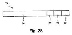
記述子73は、タイムスライシング及び/又はMPE−FECが所与のエレメンタリ・ストリームで使用されるかどうかを識別している、EN 301 192同書の節9.5に記述されたタイムスライス及びFEC識別記述子74に類似している。しかしながら、記述子73は、単一のMPE−FECフレームを送信するのに使用されるバーストの数を示すためのフィールド75、MPE−FECフレームのサイズを示すためのフィールド76、及び単一のバーストで搬送されるMPE−FECフレームの数を示すためのフィールド77を含む、付加的なフィールドを含む。バージョン番号、特にRS(255,191,64)以外の場合のコーディングのタイプ、及び特に最大バーストサイズ以外の場合の最大フレームサイズを示すことができる。
図29を参照すると、タイムスライス識別記述子73は、第1及び第2記述子ループ79、80を有するネットワーク情報テーブル(NIT)78で使用される。 Referring to FIG. 29, the time
第1記述子ループ79に位置付けられた場合、記述子73は、テーブル78内で通知された全トランスポートストリームに適用される。記述子73は、トランスポートストリームのいずれにおいても所与のストリームタイプフィールド値を有する全エレメンタリ・ストリームに適用される。0x0Dのストリームタイプフィールド値は、MPEのみのストリームを搬送するエレメンタリ・ストリームに対して使用することができる。0x80のストリームタイプフィールド値は、MPE及びFECセクションを搬送するエレメンタリ・ストリームに対して使用することができる。0x80と0xFFとの間のストリーム_タイプフィールド値は、FECセクションのみを搬送するエレメンタリ・ストリームに対して使用することができる。 When positioned in the
第2記述子ループ80に位置付けられた場合、記述子73は、トランスポートストリームフィールド(図示せず)で指定された当該トランスポートストリームに適用される。記述子73は、所与のストリームタイプフィールド値を有する全てのエレメンタリ・ストリームに適用される。この記述子73は、第1記述子ループにおける利用可能な記述子を上書きする。 When positioned in the
記述子73は、INT(図示せず)のようなテーブルの他のタイプに含むことができる。
INT(図示せず)のプラットフォーム記述子ループ(図示せず)に位置付けられた場合、記述子は、テーブルの範囲まで照会される全てのエレメンタリ・ストリームに適用される。この記述子は、NITにおける利用可能な記述子を上書きする。 When placed in an INT (not shown) platform descriptor loop (not shown), the descriptor applies to all elementary streams that are queried to the extent of the table. This descriptor overwrites the available descriptor in the NIT.
INT(図示せず)のターゲット記述子ループ(図示せず)に位置付けられた場合、記述子は、記述子の出現後に当該ターゲット記述子ループ(図示せず)内で照会される全てのエレメンタリ・ストリームに適用される。この記述子は、プラットフォーム記述子ループ及びNITにおける利用可能な記述子を上書きする。エレメンタリ・ストリームがINT内の複数のロケーションから照会される場合、各々は同じ信号方式を含む。 When placed in a target descriptor loop (not shown) of an INT (not shown), the descriptor is all the elementary queries queried in that target descriptor loop (not shown) after the appearance of the descriptor. Applied to the stream. This descriptor overrides the descriptor available in the platform descriptor loop and NIT. If an elementary stream is queried from multiple locations in the INT, each contains the same signaling.
SI/PSIセクション・エンキャプスレーティングブロック20(図2)は、NIT78をセクション(図示せず)にセグメント化し、該セクションをTSストリーム発生器及び多重化ブロック24に渡してPID=0x0010を有するTSパケット26Bにマップされ、マルチプレックス26(図2)に多重化されるようにする。The SI / PSI section encapsulating rating block 20 (FIG. 2) segments the
受信器は通常、ネットワーク1(図1)に接続するときにNIT78にアクセスするだけである。 The receiver typically only accesses the
受信器(図示せず)は、1つのトランスポートストリームから別のトランスポートストリーム(図示せず)に変わる場合にINTのコンテンツを読み出すことが必要になる場合があり、通常は2回以上読み出すことはない。INTでの変化は、PMTテーブル(図示せず)を使用してPSIで信号を送り、従って、確実にINTの一定のフィルタ処理が必要でないようにすることができる。 The receiver (not shown) may need to read the contents of the INT when changing from one transport stream to another (not shown), usually reading more than once There is no. Changes in INT can be signaled in PSI using a PMT table (not shown), thus ensuring that constant filtering of INT is not required.
PMT(図示せず)のようなPSIテーブルは通常、100ミリ秒毎に少なくとも1回再送信される。バーストの持続時間が100ミリ秒より長い場合、受信器は、バーストを受信すると同時にPMTへアクセスする。より短いバーストでは、受信器は、全ての必要とされるPSIテーブルが受信されるまでスイッチをオンに保持するよう選択することができる。 A PSI table such as a PMT (not shown) is typically retransmitted at least once every 100 milliseconds. If the duration of the burst is longer than 100 milliseconds, the receiver accesses the PMT upon receiving the burst. For shorter bursts, the receiver can choose to keep the switch on until all required PSI tables are received.
移動端末2
図30を参照すると、デジタルブロードキャスティングネットワーク1(図1)からコンテンツを受信するための移動端末2が示されている。
Referring to FIG. 30, a
移動端末2は、マルチメディア機能を有する携帯電話ハンドセットの形式である。移動端末2は、第1及び第2アンテナ811、812、受信器821、及び送受信器822を含む。この実施例では、第1アンテナ811及び受信器821は、ブロードキャスティングネットワーク1(図1)から信号を受信するのに使用される。第2アンテナ812及び送受信器822は、PLMNのような第2通信ネットワーク(図示せず)に信号を送信し、これから信号を受信するのに使用される。受信器及び送受信器811、822は各々、受信信号を増幅し且つ復調するためのそれぞれの無線周波数信号処理回路(図示せず)と、チャンネル復号及び逆多重化のためのそれぞれのプロセッサ(図示せず)とを含む。The
移動端末2はまた、プロセッサ83、ユーザーインターフェース84、メモリ85、オプションのスマートカードリーダー86、スマートカードリーダー86に収容されるオプションのスマートカード87、コーダ/デコーダ(コーデック)88、対応する増幅器90を備えたスピーカー89、及び対応する前置増幅器92を備えたマイクロフォン91を含む。 The
ユーザーインターフェース84は、ディスプレイ93及びキーパッド94を含む。ディスプレイ93は、例えば、従来の携帯電話のディスプレイよりも大きく及び/又はより優れた解像度を有し、カラー画像が可能であることで画像及びビデオを表示するように適合されている。移動端末2はまたバッテリー95を含む。 The
プロセッサ83は、メモリ85に記憶されたコンピュータソフトウェア(図示せず)の指示の下で移動端末2のオペレーションを管理する。例えば、コントローラ83は、ディスプレイ93への出力を可能にし、キーパッド94からの入力を受け取る。 The
移動端末2は、ブロードキャスティングネットワーク1(図1)及び第2通信ネットワーク(図示せず)から信号を受信するように適合された単一の受信器と、第2通信ネットワーク(図示せず)に信号を送信するように適合された送信器とを設けるように修正することができる。或いは、両方の通信ネットワークのための単一の送受信器を備えることができる。 The
図31を参照すると、受信器821は、無線周波数信号8を復調し、プロセッサ83によって処理するためのTSパケット26を出力するための復調器96を含む。しかしながら処理は、プロセッサ83によって実行する必要はなく、受信器821内で、或いは専用デジタル信号プロセッサ(図示せず)で行ってもよい。プロセッサ83によって実行されるプロセスは、図31に機能ブロック図として示されている。Referring to FIG. 31, the
TSフィルタリングブロック97は、TSストリーム25’を受信し、TSパケットヘッダ70(図26)内に保持されるPID値71(図26)に従ってTSパケット25A、25Bをフィルタ処理し、フィルタ処理されたTSパケット25A、25Bをセクションパージングブロック98に渡す。MPEG−2TVを搬送するTSパケット25Cもまた、従来の方式でフィルタ及び処理される。The
セクションパージングブロック98は、TSパケット25A、25Bのペイロード72(図26)をデキャプスレートし、MPEセクション16、MPE−FECセクション17、及びSI/PSIテーブルセクション22を出力する。テーブルセクション21は、NIT78(図29)及びINT(図示せず)を搬送するセクション(図示せず)を含む。The
移動端末2がユーザーによってスイッチオンされた場合、TSフィルタリングブロック97は、ユーザーが利用したいサービス(又は複数のサービス)を提供するフィルタ処理されたストリーム12を搬送するTSパケット25AのPID値を知らない可能性がある。従って、最初に、TSフィルタリングブロック97は、例えばEN 301 192同書に記載されるようなサービス発見に使用されるNIT78(図29)及びINT(図示せず)を搬送するTSパケット25Bだけを受信しフィルタ処理することができる。ユーザーには、サービスを選択することができる電子サービスガイド(図示せず)が提示される。プロセッサ83(図30)は、NIT78(図29)又はINT(図示せず)において選択されたサービスのPIDを探し、TSフィルタリングブロック97にPIDを提供してTSパケット25Aをフィルタ処理するようにする。When the
セクション・デキャプスレーティングブロック99は、MPE及びMPE−FECセクション16、17のヘッダ46、49(図13及び14)からリアルタイムパラメータであるframe_id及びframe_counterパラメータを抽出し、これらをコントローラブロック100に提供する。 The section
セクション・デキャプスレーティングブロック99は、MPE及びMPE−FECセクション16、17のペイロード47、50(図13及び14)並びにSI/PSIテーブルセクション21からデータグラム及びRS列を抽出し、これらをMPE−FEC復号ブロック102及びPSI/SIパーサ103にそれぞれ転送する。セクション・デキャプスレーティングブロック99はまた、アドレス43(図13)をMPE−FEC復号ブロック102に転送する。 The
コントローラブロック100はまた、リアルタイムパラメータを分析し、受信器821にスイッチオフするか或いは電力を節約するように命令する制御信号104を生成する。コントローラブロック100はまた、他の処理ブロックにスイッチオフ又は電力を節約するように命令する他の制御信号(図示せず)を生成することができる。The
コントローラブロック100はまたリアルタイムパラメータを分析し、バーストの終わりが失われた場合に復号を始めるようMPE−FEC復号ブロック102に命令する制御信号105を生成する。 The
MPE−FEC復号ブロック102は、1つ又はそれ以上の復号テーブル106を含む。以下に詳細に説明するように、復号テーブル106の数及びサイズは、MPE−FECフレーム構成に基づいて決定することができる。 The MPE-
MPE−FEC復号ブロック102は、IPパージング及びフィルタリングブロック107に出力し、フィルタ処理されたストリーム12をIPアドレスに従ってIPストリーム9をフィルタリングする。 The MPE-
図30、31、及び32を参照し、移動端末2の動作方法について説明する。 The operation method of the
移動端末2がユーザーによって或いは別の適切な時間にスイッチオンされると、プロセッサ83はNIT78(図29)及びINT(図示せず)をダウンロードし、これらをメモリ85内に記憶する(ステップS18及びS19)。 When the
NIT(図29)及びINT(図示せず)を使用して、必要な場合に適切なSIテーブル(図示せず)をダウンロードし、これによって電子サービスガイド(ESG)(図示せず)を提供できるようにする。移動端末ユーザー(図示せず)は、ディスプレイ93を介してESGを閲覧し、キーパッド94を使用してサービスを選択することができる(ステップS19)。 NIT (FIG. 29) and INT (not shown) can be used to download the appropriate SI table (not shown) when needed, thereby providing an electronic service guide (ESG) (not shown) Like that. A mobile terminal user (not shown) can browse the ESG via the
ユーザーは、フィルタ処理されたストリーム121、122(図4)によって提供されるサービスを利用することを望む。The user desires to use the service provided by the filtered
サービスが選択されると、プロセッサ83は、対応するタイムスライス及びFEC識別記述子73についてメモリ85内に記憶されたネットワークNIT78をサーチする。プロセッサ83は、記述子73のタイムスライシング、MPE FEC、最大バースト持続時間、最大平均レート、バーストサイズ及びフレームサイズ、並びにタイムスライス・アイデンティティフィールド(図示せず)を調べ、タイムスライシング及びMPE−FECが使用されるかどうかを判定し、使用される場合には、タイムスライシング及びMPE−FECパラメータを収集する。 When a service is selected, the
更に、プロセッサ83は、バースト番号フィールド75、フレームサイズフィールド76、MPE−FECフレーム番号フィールド77、及びバーストサイズフィールドを調べ、単一のMPE−FECフレームを送信するのに使用されるバーストの数、MPE−FECフレームのサイズ及び単一のバーストで搬送されるMPE−FECフレームの数を求める。これらのパラメータは、TSフィルタリングブロック97、セクションデマルチプレクサ99、及びMPE−FEC復号ブロック102に渡される。 In addition, the
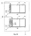
図33を参照すると、MPE−FEC復号ブロック102は、バッファ106、この実施例では第1及び第2バッファ1061、1062を作成し、これらは、第1及び第2コーディングテーブル271、272(図7)に対応し、それぞれアプリケーションデータテーブル1071、1072、RSデータテーブル1081、1082を含み、255列1091、1092と1024行1101、1102を有し、バッファ1061、1062内の各ポジション1111、1112が1バイトのデータを保持している(ステップS21)。バッファ106を作成する段階は、サイズL×2メガビット(L>1)を有する単一のバッファの部分を所与のMPE−FECフレームに割り当てる段階を含むことができる。Referring to FIG. 33, the MPE-
受信器821がまだスイッチオンされていない場合、コントローラ100は、受信器821にスイッチオンを命令する(ステップS22)。If the
受信器821は信号8を復調し、TSストリーム25’を出力する。TSストリーム25’は、マルチプレックス25(図27)の少なくとも一部を含む。The
TSフィルタリングブロック97は、PID71(図26)に従ってTSパケット25A(図25)をフィルタ処理する(ステップS23)。TSフィルタリングブロック97は、誤りを含むあらゆるTSパケット25Aを廃棄することができる。The
セクションパージングブロック98はTSパケット25Aを受信し、TSパケット25Aからセクションフラグメント69(図25)をデキャプスレートして、例えば、図17に示されるものに類似したMPEセクション16及びMPE−FECセクション17を出力する(ステップS24)。
図34を参照すると、セクション・デキャプスレーティングブロック99は、MPEセクション16及びMPE−FECセクション17を受信し、MPE及びMPE−FECセクション16、17からのそのペイロード47、50からデータグラム28及びRS列40をデキャプスレートし(ステップS25)、ヘッダ46、49からアドレス(ステップS26)、フレームアイデンティティ及びフレームカウンタパラメータ(ステップS27)、並びにバースト番号(ステップS28)を含むリアルタイムパラメータを抽出する。 Referring to FIG. 34,
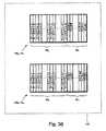
図35を参照すると、MPE−FEC復号ブロック102は、対応するフレームアイデンティティ及びフレームカウンタパラメータ41、42、アドレスデータ43、テーブルフラグ44、バーストエンドフラグ45、及びバーストカウンタ60と共に、例えばデータグラム281,1、281,2、282,1、282,2、282,3、282,4を含むデータグラム281、282及びRS列401、402を受信する。Referring to FIG. 35, the MPE-
フレームアイデンティティパラメータ41に基づいて、MPE−FEC復号ブロック106は、データグラム28及びRS列40を第1及び第2バッファ1061、1062に配向し、これらをアドレスデータ43に従って第1及び第2バッファ1061、1062に配置する(ステップS29)。Based on the
MPE−FEC復号ブロック102は、バーストの終わりに達したかどうかをチェックする(ステップS30)。これは、リアルタイムパラメータフィールド54、59(図15及び16)におけるバーストエンドフィールドをチェックする段階と、「1」がバーストの終わりを示す場合にバーストエンドフィールドが「1」に等しいかどうかを判定する段階を含む。バーストの終わりに達していない場合、TSパケット25A及びセクション16、17の処理は継続する(ステップS23からS30)。The MPE-
バーストの終わりに達した場合、MPE−FEC復号ブロック102は、同じMPE−FECフレームから追加のデータを搬送する更なるバーストが予期されるかどうかをチェックする(ステップS31)。これは、バーストカウンタ60をチェックする段階と、バーストカウンタが「0」に等しいかどうかを判定する段階とを含む。これはまた、バーストが複数のMPE−FECフレーム全体を含む単一のバーストであるかどうかをチェックするのに使用することができる。 When the end of the burst is reached, the MPE-
図36を参照すると、バーストが1つ又はそれ以上のMPE−FECフレームを搬送する順番の終わりであることによるかどうかに関係なく、或いはバーストが複数のMPE−FECフレーム全体を含むか否かに関係なく、同じMPE−FECフレームから追加のデータを搬送する更なるバーストが予期されない場合には、前記又は各MPE−FECフレーム141、142は、受信が完了したと見なすことができる。Referring to FIG. 36, regardless of whether the burst is due to the end of the order of carrying one or more MPE-FEC frames, or whether the burst includes multiple MPE-FEC frames. Regardless, if no further bursts are expected to carry additional data from the same MPE-FEC frame, the or each MPE-
MPE−FEC復号ブロック102は、RS列401、402を受信する必要がないか、或いは無視することができる。The MPE-
図37を参照すると、MPE−FEC復号ブロック102は、前記又は各MPE−FECフレーム141、142を復号する(ステップS31)。これは、RSコードワード381、382を使用して、誤りバイト1121,1などの誤りをチェックし訂正する段階を含む。Referring to FIG. 37, the MPE-
MPE−FEC復号ブロック102は、前記又は各MPE−FECフレーム141、142を復号する必要はない。The MPE-
MPE−FEC復号ブロック102は、バッファ1061、1062からデータグラム281、282を読み出す(ステップS33)。The MPE-
フィルタリングブロック107は、そのIPアドレスに従ってデータグラム281、282をフィルタ処理し、これらをアプリケーション(図示せず)又はメモリに渡して、記憶、追加処理、レンダリング、又は他の利用を行う(ステップS33)。サービスが配信されたか或いはこれ以上必要とされない場合、このサービスのTSパケット25Aの受信及び処理を中止することができる(ステップS35)。
更なるバーストが予期される場合、コントローラ100は、受信器821にスイッチオフを命令(ステップS36)し、好ましくはバーストの最後のセクションで受信された値を使用してデルタ−tを待機し(ステップS37)、更に、次のバーストを受信するために受信器821にスイッチオンするよう命令する(ステップS22)。If further bursts are expected, the
図38を参照すると、2メガビットよりも大きなMPE−FECフレーム、例えばMPE−FECフレーム141,1’(図22)が受信されることになる場合、従来のタイムスライシングバッファよりも大きい、すなわち2メガビットよりも大きい復号テーブル1061’を作成することができる。Referring to FIG. 38, if an MPE-FEC frame larger than 2 megabits, for example MPE-
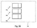
図39を参照すると、複数のMPE−FECフレーム、例えばMPE−FECフレーム143,1、144,1、145,1が単一のバーストで受信される場合、それぞれの復号テーブル1063、1064、1065を作成することができる。Referring to FIG. 39, when a plurality of MPE-FEC frames, eg, MPE-FEC frames 143,1 , 144,1 , 145,1 are received in a single burst, the respective decoding tables 1063 , 1064 and 1065 can be created.
上記に記載された実施形態に対し多くの修正を行うことができる点は理解されるであろう。例えば、移動端末2は、少なくとも第1通信ネットワーク1を介して信号を受信できるパーソナルデータアシスタント(PDA)又は他の移動端末とすることができる。移動端末はまた、自動車などの乗物において搬送される端末のような半固定又は半携帯型端末とすることができる。 It will be appreciated that many modifications can be made to the embodiments described above. For example, the
6 MPEエンキャプスレータ
7 送信器
11 デマルチプレックス
13 MPE−FEC符号化 テーブル
15 MPE/MPE−FECセクションエンキャプスレーティング
18 タイムスライシング
20 SI/PSIセクションエンキャプスレーティング
22 制御
23 多重化
26 DVB−T変調6
Claims (27)
Translated fromJapaneseデータの第1セットと順方向誤り訂正(FEC)データの対応する第1セットとを含む第1データフレームを提供する段階と、
バーストのシーケンスを形成する段階と、
前記第1データフレームを前記バースト間で分割する段階と、
を含み、前記データの第1セットが少なくとも2つのバースト間で分割されることを特徴とする方法。A method for transmitting bursts in a digital broadcasting network,
Providing a first data frame including a first set of data and a corresponding first set of forward error correction (FEC) data;
Forming a sequence of bursts;
Dividing the first data frame between the bursts;
And the first set of data is divided between at least two bursts.
前記第2データフレームにおいて前記第2データと前記FECデータの第2セットとを前記複数のバースト間で分割する段階と、
を更に含む請求項1に記載の方法。Providing a second data frame including a second set of data and a corresponding second set of FEC data;
Dividing the second data and the second set of FEC data between the plurality of bursts in the second data frame;
The method of claim 1 further comprising:
前記第2データフレームをデータフレームブロックの第2セットに分割する段階と、
前記データフレームブロックの第1及び第2セットをインターリーブする段階と、
前記インターリーブされたデータフレームブロックを前記複数のバーストに順次配置する段階と、
を含む請求項3に記載の方法。Dividing the first data frame into a first set of data frame blocks;
Dividing the second data frame into a second set of data frame blocks;
Interleaving the first and second sets of data frame blocks;
Sequentially placing the interleaved data frame blocks in the plurality of bursts;
The method of claim 3 comprising:
第1及び第2部分を含む第1アレイを提供する段階と、
前記第1アレイ部分の少なくとも一部を前記データの第1セットで満たす段階と、
前記第1アレイ部分のデータに基づいて前記FECデータの第1セットを求める段階と、
前記FECデータの第1セットを前記第2アレイ部分に配置する段階と、
を含む請求項1に記載の方法。Providing the first data frame comprises:
Providing a first array including first and second portions;
Filling at least a portion of the first array portion with the first set of data;
Determining a first set of FEC data based on the data of the first array portion;
Placing the first set of FEC data in the second array portion;
The method of claim 1 comprising:
前記対応するFECデータをMPEセクションの第2セットにエンキャプスレートする段階と、
を含む請求項1に記載の方法。Encapsulating the first set of data into a first set of multi-protocol encapsulation (MPE) sections;
Encapsulating the corresponding FEC data into a second set of MPE sections;
The method of claim 1 comprising:
前記MPEセクションの第1及び第2セットを時間的にオフセットされたグループに構成する段階を含む請求項9に記載の方法。Forming the plurality of bursts comprises:
The method of claim 9, comprising configuring the first and second sets of MPE sections into temporally offset groups.
データの第1セットと順方向誤り訂正(FEC)データの対応する第1セットとを含む第1データフレームを提供する段階と、
データの第2セットとFECデータの対応する第2セットとを含む第2データフレームを提供する段階と、
前記第1及び第2データフレームを含むバーストを形成する段階と、
を含む方法。A method for transmitting bursts in a digital broadcasting network,
Providing a first data frame including a first set of data and a corresponding first set of forward error correction (FEC) data;
Providing a second data frame including a second set of data and a corresponding second set of FEC data;
Forming a burst including the first and second data frames;
Including methods.
データフレームのためのデータを含む第1バーストを受信する段階と、
前記データをデータフレーム内に配置する段階と、
前記第1バーストを含むバーストのシーケンスにおける第2バーストが従う指標を前記第1バーストから抽出する段階と、
前記データフレームのための追加のデータを含む前記第2バーストを受信する段階と、
前記追加データを前記データフレーム内に配置する段階と、
を含む方法。A method of operating a terminal for receiving a burst from a digital broadcasting network, comprising:
Receiving a first burst containing data for a data frame;
Placing the data in a data frame;
Extracting from said first burst an indication that a second burst follows in a sequence of bursts including said first burst;
Receiving the second burst including additional data for the data frame;
Placing the additional data in the data frame;
Including methods.
複数のデータフレームのためのデータを含むバーストを受信する段階と、
データのセットと該データのセットが属するデータフレームに関する指標とを前記バーストから抽出する段階と、
前記データの各セットを対応するデータフレーム内に配置する段階と、
を含む方法。A method of operating a terminal for receiving a burst from a digital broadcasting network, comprising:
Receiving a burst including data for a plurality of data frames;
Extracting from the burst a set of data and an indication of the data frame to which the set of data belongs;
Placing each set of data in a corresponding data frame;
Including methods.
データの第1セットと順方向誤り訂正(FEC)データの対応する第1セットとを含む第1データフレームを提供させ、
バーストのシーケンスを形成させ、
前記データの第1セットが少なくとも2つのバースト間で分割されるように前記第1データフレームを前記バースト間で分割させる命令を含むコンピュータプログラム。For data processing equipment
Providing a first data frame comprising a first set of data and a corresponding first set of forward error correction (FEC) data;
Form a sequence of bursts,
A computer program comprising instructions for dividing the first data frame between the bursts such that the first set of data is divided between at least two bursts.
データの第1セットと順方向誤り訂正(FEC)データの対応する第1セットとを含む第1データフレームを提供させ、
データの第2セットとFECデータの対応する第2セットとを含む第2データフレームを提供させ、
前記第1及び第2データフレームを含むバーストを形成させる命令を含むコンピュータプログラム。For data processing equipment
Providing a first data frame comprising a first set of data and a corresponding first set of forward error correction (FEC) data;
Providing a second data frame comprising a second set of data and a corresponding second set of FEC data;
A computer program comprising instructions for forming a burst including the first and second data frames.
データフレームのためのデータを含む第1バーストを受信させ、
前記データをデータフレーム内に配置させ、
前記第1バーストを含むバーストのシーケンスにおいて第2バーストが従う指標を前記第1バーストから抽出させ、
前記データフレームのための追加データを含む前記第2バーストを受信させ、
前記追加データを前記データフレーム内に配置させるための命令を含むコンピュータプログラム。For data processing equipment
Receiving a first burst including data for a data frame;
Placing the data in a data frame;
Extracting from the first burst an index followed by a second burst in a sequence of bursts including the first burst;
Receiving the second burst including additional data for the data frame;
A computer program comprising instructions for placing the additional data in the data frame.
複数のデータフレームのためのデータを含むバーストを受信させ、
データのセットと該データのセットが属するデータフレームに関する指標とを前記バーストから抽出させ、
前記データの各セットを対応するデータフレーム内に配置させるための命令を含むコンピュータプログラム。For data processing equipment
Receiving a burst containing data for multiple data frames;
Extracting from the burst a set of data and an indication of the data frame to which the set of data belongs;
A computer program comprising instructions for placing each set of data in a corresponding data frame.
データの第1セットと順方向誤り訂正(FEC)データの対応する第1セットとを含む第1データフレームを提供する段階と、
バーストのシーケンスを形成する段階と、
前記第1データフレームを前記バースト間で分割する段階と、
を含み、
前記データの第1セットは少なくとも2つのバースト間で分割されることを特徴とするシステム。A system for transmitting bursts in a digital broadcasting network,
Providing a first data frame including a first set of data and a corresponding first set of forward error correction (FEC) data;
Forming a sequence of bursts;
Dividing the first data frame between the bursts;
Including
The system, wherein the first set of data is divided between at least two bursts.
データの第1セットと順方向誤り訂正(FEC)データの対応する第1セットとを含む第1データフレームを提供する段階と、
データの第2セットとFECデータの対応する第2セットとを含む第2データフレームを提供する段階と、
前記第1及び第2データフレームを含むバーストを形成する段階と、
を含むシステム。A system for transmitting bursts in a digital broadcasting network,
Providing a first data frame including a first set of data and a corresponding first set of forward error correction (FEC) data;
Providing a second data frame including a second set of data and a corresponding second set of FEC data;
Forming a burst including the first and second data frames;
Including system.
バーストのシーケンスを形成し、
前記データの第1セットが少なくとも2つのバースト間で分割されるように前記第1データフレームを前記バースト間で分割する、
ように構成されたネットワーク要素。Providing a first data frame comprising a first set of data and a corresponding first set of forward error correction (FEC) data;
Form a sequence of bursts,
Dividing the first data frame between the bursts such that the first set of data is divided between at least two bursts;
Network elements configured as follows:
データの第2セットとFECデータの対応する第2セットとを含む第2データフレームを提供し、
前記第1及び第2データフレームを含むバーストを形成する、
ように構成されたネットワーク要素。Providing a first data frame comprising a first set of data and a corresponding first set of forward error correction (FEC) data;
Providing a second data frame comprising a second set of data and a corresponding second set of FEC data;
Forming a burst including the first and second data frames;
Network elements configured as follows:
データフレームのためのデータを含む第1バーストを受信し、
前記データをデータフレーム内に配置し、
前記第1バーストを含むバーストのシーケンスにおける第2バーストが従う指標を前記第1バーストから抽出し、
前記データフレームのための追加データを含む前記第2バーストを受信し、
前記追加データを前記データフレーム内に配置する、
ように構成された端末。A terminal for receiving a burst from a digital broadcasting network,
Receiving a first burst including data for a data frame;
Placing the data in a data frame;
Extracting from said first burst an indication that a second burst follows in a sequence of bursts including said first burst;
Receiving the second burst including additional data for the data frame;
Placing the additional data in the data frame;
Terminal configured as follows.
複数のデータフレームのためのデータを含むバーストを受信し、
データのセットと該データのセットが属するデータフレームに関する指標とを前記バーストから抽出し、
前記データを対応するデータフレーム内に配置する、
ように構成された端末。A terminal for receiving a burst from a digital broadcasting network,
Receive bursts containing data for multiple data frames,
Extracting from the burst a set of data and an indication of the data frame to which the set of data belongs;
Placing the data in a corresponding data frame;
Terminal configured as follows.
Applications Claiming Priority (3)
| Application Number | Priority Date | Filing Date | Title |
|---|---|---|---|
| GB0420540AGB0420540D0 (en) | 2004-09-15 | 2004-09-15 | Burst transmission in a digital broadcasting network |
| GB0420540.7 | 2004-09-15 | ||
| PCT/IB2005/052677WO2006030329A1 (en) | 2004-09-15 | 2005-08-12 | Burst transmission in a digital broadcasting network |
Related Child Applications (1)
| Application Number | Title | Priority Date | Filing Date |
|---|---|---|---|
| JP2011028595ADivisionJP2011151813A (en) | 2004-09-15 | 2011-02-14 | Burst transmission in digital broadcasting network |
Publications (2)
| Publication Number | Publication Date |
|---|---|
| JP2008514084Atrue JP2008514084A (en) | 2008-05-01 |
| JP5097547B2 JP5097547B2 (en) | 2012-12-12 |
Family
ID=33306635
Family Applications (2)
| Application Number | Title | Priority Date | Filing Date |
|---|---|---|---|
| JP2007531880AExpired - LifetimeJP5097547B2 (en) | 2004-09-15 | 2005-08-12 | Burst transmission in digital broadcasting networks |
| JP2011028595APendingJP2011151813A (en) | 2004-09-15 | 2011-02-14 | Burst transmission in digital broadcasting network |
Family Applications After (1)
| Application Number | Title | Priority Date | Filing Date |
|---|---|---|---|
| JP2011028595APendingJP2011151813A (en) | 2004-09-15 | 2011-02-14 | Burst transmission in digital broadcasting network |
Country Status (11)
| Country | Link |
|---|---|
| US (1) | US8209586B2 (en) |
| EP (1) | EP1790097B1 (en) |
| JP (2) | JP5097547B2 (en) |
| KR (1) | KR100891902B1 (en) |
| CN (1) | CN101040469B (en) |
| AU (1) | AU2005283852B2 (en) |
| BR (1) | BRPI0519989B1 (en) |
| CA (1) | CA2580396A1 (en) |
| GB (1) | GB0420540D0 (en) |
| TW (1) | TWI377805B (en) |
| WO (1) | WO2006030329A1 (en) |
Cited By (4)
| Publication number | Priority date | Publication date | Assignee | Title |
|---|---|---|---|---|
| JP2010200252A (en)* | 2009-02-27 | 2010-09-09 | Toshiba Corp | Device, method and program for transmitting data |
| JP2013521720A (en)* | 2010-03-03 | 2013-06-10 | クゥアルコム・インコーポレイテッド | Block aggregation of objects in communication systems |
| WO2020129325A1 (en)* | 2018-12-21 | 2020-06-25 | ソニーセミコンダクタソリューションズ株式会社 | Receiver and receiver control method |
| WO2020203094A1 (en)* | 2019-04-05 | 2020-10-08 | ソニーセミコンダクタソリューションズ株式会社 | Receiving device, receiving method and receiving program |
Families Citing this family (30)
| Publication number | Priority date | Publication date | Assignee | Title |
|---|---|---|---|---|
| WO2006073284A1 (en)* | 2005-01-07 | 2006-07-13 | Samsung Electronics Co., Ltd. | Apparatus and method for transmitting/receiving multiuser packet in a mobile communication system |
| US7823048B2 (en) | 2005-05-31 | 2010-10-26 | Nokia Corporation | Buffering of data from a data stream having error correction elements |
| FR2890274A1 (en)* | 2005-08-30 | 2007-03-02 | France Telecom | Digital data broadcasting service address transforming method for telecommunication network, involves recovering data of broadcasting service address, and inserting part of identifying data in Internet protocol address of datagrams |
| TWI401910B (en)* | 2005-09-19 | 2013-07-11 | St Ericsson Sa | Apparatus and method for error correction in mobile wireless applications incorporating multi-level and adaptive erasure data |
| KR100827075B1 (en)* | 2006-01-20 | 2008-05-02 | 삼성전자주식회사 | Apparatus and method for receiving broadcast data in digital video broadcasting receiver |
| WO2007091779A1 (en) | 2006-02-10 | 2007-08-16 | Lg Electronics Inc. | Digital broadcasting receiver and method of processing data |
| US7577898B2 (en)* | 2006-04-10 | 2009-08-18 | At&T Intellectual Property I, L.P. | System and method of correcting video data errors |
| DE602006004005D1 (en) | 2006-04-25 | 2009-01-15 | Dibcom | Device and method for power management |
| WO2007126196A1 (en) | 2006-04-29 | 2007-11-08 | Lg Electronics Inc. | Digital broadcasting system and method of processing data |
| BR122012022087B1 (en) | 2006-05-11 | 2020-04-14 | Interdigital Ce Patent Holdings | method and apparatus for transmitting data |
| WO2007136166A1 (en) | 2006-05-23 | 2007-11-29 | Lg Electronics Inc. | Digital broadcasting system and method of processing data |
| US7525993B2 (en)* | 2006-05-24 | 2009-04-28 | Newport Media, Inc. | Robust transmission system and method for mobile television applications |
| US8732559B2 (en) | 2006-07-25 | 2014-05-20 | Thomson Licensing | Recovery from burst packet loss in internet protocol based wireless networks using staggercasting and cross-packet forward error correction |
| US7873104B2 (en) | 2006-10-12 | 2011-01-18 | Lg Electronics Inc. | Digital television transmitting system and receiving system and method of processing broadcasting data |
| KR101253176B1 (en)* | 2006-11-02 | 2013-04-10 | 엘지전자 주식회사 | Digital broadcasting system and data processing method |
| KR101221913B1 (en) | 2006-12-20 | 2013-01-15 | 엘지전자 주식회사 | Digital broadcasting system and data processing method |
| KR101285887B1 (en) | 2007-03-26 | 2013-07-11 | 엘지전자 주식회사 | Digital broadcasting system and method of processing data in digital broadcasting system |
| KR101253185B1 (en) | 2007-03-26 | 2013-04-10 | 엘지전자 주식회사 | Digital broadcasting system and data processing method |
| KR101285888B1 (en) | 2007-03-30 | 2013-07-11 | 엘지전자 주식회사 | Digital broadcasting system and method of processing data in digital broadcasting system |
| EP2009828B1 (en)* | 2007-06-28 | 2016-01-27 | Alcatel Lucent | Method for providing unequal error protection to data packets in a burst transmission system |
| WO2009005326A2 (en) | 2007-07-04 | 2009-01-08 | Lg Electronics Inc. | Digital broadcasting system and method of processing data |
| US8332896B2 (en) | 2007-07-05 | 2012-12-11 | Coherent Logix, Incorporated | Transmission of multimedia streams to mobile devices with cross stream association |
| US8358687B2 (en)* | 2007-09-07 | 2013-01-22 | Qualcomm Incorporated | Method and apparatus for receiving multiple simultaneous stream bursts with limited DVB receiver memory |
| US10320500B2 (en)* | 2007-09-18 | 2019-06-11 | Qualcomm Incorporated | Method and apparatus to enable fast channel switching with limited DVB receiver memory |
| EP2238798B1 (en)* | 2008-01-29 | 2018-05-16 | Nokia Technologies Oy | System and method for burst separation and extended interleaving length |
| KR101107316B1 (en)* | 2008-12-18 | 2012-01-20 | 한국전자통신연구원 | Pixel Interleaving Method of Distributed Image Codec |
| KR20120005371A (en)* | 2010-07-08 | 2012-01-16 | 한국전자통신연구원 | Method and apparatus for recovering burst data loss by overlapping block code symbols |
| CN102088640A (en)* | 2011-01-10 | 2011-06-08 | 西安电子科技大学 | Adaptive selection retransmission method based on video content |
| KR101765123B1 (en)* | 2011-01-14 | 2017-08-04 | 삼성전자주식회사 | Apparatus and method for providing transmission signal in communication system |
| CN103138849B (en)* | 2011-11-23 | 2016-12-07 | 深圳市中兴微电子技术有限公司 | A kind of special burst sequence detecting method and system |
Citations (9)
| Publication number | Priority date | Publication date | Assignee | Title |
|---|---|---|---|---|
| JPH04290316A (en)* | 1991-03-19 | 1992-10-14 | Fujitsu Ltd | Bit error reduction system |
| JPH07170246A (en)* | 1993-07-05 | 1995-07-04 | Mitsubishi Electric Corp | Transmission frame error control transmission device, error control reception device, transmission frame with error correction code transmission method and reception method |
| JPH09214473A (en)* | 1996-02-06 | 1997-08-15 | Fujitsu Ltd | Interleaved communication system and its device |
| JPH10117335A (en)* | 1996-10-08 | 1998-05-06 | Toshiba Corp | Information processing device for video-on-demand system |
| JPH11355854A (en)* | 1998-06-10 | 1999-12-24 | Matsushita Electric Ind Co Ltd | Digital data transmitting / receiving method, base station apparatus used for transmitting / receiving digital data, and mobile terminal apparatus used for transmitting / receiving digital data |
| JP2000324068A (en)* | 1999-05-13 | 2000-11-24 | Sony Corp | Signal processing unit, its method and computer-readable medium |
| EP1337071A2 (en)* | 2002-02-14 | 2003-08-20 | Nokia Corporation | Transmission burst time indications for power saving |
| WO2003069885A2 (en)* | 2002-02-14 | 2003-08-21 | Nokia Corporation | Time-slice signaling for broadband digital broadcasting |
| JP2004088388A (en)* | 2002-08-27 | 2004-03-18 | Ntt Data Corp | Receiver, method for processing received data, and program |
Family Cites Families (34)
| Publication number | Priority date | Publication date | Assignee | Title |
|---|---|---|---|---|
| US5371734A (en)* | 1993-01-29 | 1994-12-06 | Digital Ocean, Inc. | Medium access control protocol for wireless network |
| US5382949A (en)* | 1993-02-01 | 1995-01-17 | Motorola, Inc. | Method for increasing battery life for selective call receivers |
| US6175557B1 (en)* | 1994-10-31 | 2001-01-16 | Telefonaktiebolaget Lm Ericsson (Publ) | Layer 2 protocol in a cellular communication system |
| DE69634607T2 (en)* | 1995-10-24 | 2006-03-02 | General Instrument Corporation | VARIABLE LENGTH BURST TRANSMISSION OVER THE PHYSICAL LAYER OF A MULTILAYER TRANSMISSION FORMAT |
| US5923655A (en)* | 1997-06-10 | 1999-07-13 | E--Net, Inc. | Interactive video communication over a packet data network |
| US6101465A (en)* | 1997-06-12 | 2000-08-08 | Advanced Micro Devices, Inc. | System and method for bit interleaving of full-rate speech data |
| US6035434A (en)* | 1997-06-12 | 2000-03-07 | Advanced Micro Devices, Inc. | System and method for bit interleaving of half-rate speech data |
| US6577610B1 (en) | 1997-06-30 | 2003-06-10 | Spacenet, Inc. | Flex slotted Aloha transmission system and method |
| US6839332B1 (en)* | 1997-10-20 | 2005-01-04 | Comsat Corporation | Method for transmission of circuits, packets, and cells in a satellite/wireless TDMA system |
| JPH11196072A (en)* | 1997-12-30 | 1999-07-21 | Sony Corp | Error correction encoding method and device and data transmission method |
| JP3540154B2 (en)* | 1998-05-20 | 2004-07-07 | 三菱電機株式会社 | Multiplexing transmission device and multiplexing transmission method |
| DE69922342T2 (en)* | 1999-04-19 | 2005-05-12 | Alcatel | TDMA multipoint-to-point system using a special burst structure and associated transmitters |
| CA2373678A1 (en)* | 2000-03-10 | 2001-09-20 | Hughes Electronics Corporation | Apparatus and method for efficient tdma bandwidth allocation for tcp/ip satellite-based networks |
| US6993009B2 (en)* | 2000-03-10 | 2006-01-31 | Hughes Electronics Corporation | Method and apparatus for deriving uplink timing from asynchronous traffic across multiple transport streams |
| US6920113B1 (en)* | 2000-03-28 | 2005-07-19 | Telsima Inc. | Transport of iscochronous and bursty data on a sonet ring |
| US6441782B2 (en)* | 2000-04-14 | 2002-08-27 | Hughes Electronics Corporation | Method and system of directing an antenna in a two-way satellite system |
| US7305696B2 (en)* | 2000-04-17 | 2007-12-04 | Triveni Digital, Inc. | Three part architecture for digital television data broadcasting |
| JP4290316B2 (en) | 2000-05-11 | 2009-07-01 | Necエレクトロニクス株式会社 | Inspection method and inspection device for wiring short-circuited portion |
| US6477382B1 (en)* | 2000-06-12 | 2002-11-05 | Intel Corporation | Flexible paging for packet data |
| US6842441B2 (en)* | 2000-12-19 | 2005-01-11 | Lucent Technologies Inc. | Data transmission in a wireless communication system |
| US7230978B2 (en)* | 2000-12-29 | 2007-06-12 | Infineon Technologies Ag | Channel CODEC processor configurable for multiple wireless communications standards |
| SE0101034L (en) | 2001-03-23 | 2002-09-24 | Etheractive Solutions Ab | Portable receiver, broadcast radio system and method for controlling this |
| US8077679B2 (en) | 2001-03-28 | 2011-12-13 | Qualcomm Incorporated | Method and apparatus for providing protocol options in a wireless communication system |
| WO2003001338A2 (en) | 2001-06-22 | 2003-01-03 | Broadcom Corporation | System, method and computer program product for mitigating burst noise in a communications system |
| US7089478B2 (en)* | 2001-06-22 | 2006-08-08 | Broadcom Corporation | FEC block reconstruction system, method and computer program product for mitigating burst noise in a communications system |
| US7352817B2 (en)* | 2002-09-27 | 2008-04-01 | Ibiquity Digital Corporation | Method and apparatus for interleaving signal bits in a digital audio broadcasting system |
| JP4975967B2 (en)* | 2003-01-21 | 2012-07-11 | ノキア コーポレイション | Method, system and network entity for providing digital broadband transmission |
| EP1599961A1 (en)* | 2003-03-05 | 2005-11-30 | Nokia Corporation | Method and system for forward error correction |
| JP4461095B2 (en)* | 2003-03-10 | 2010-05-12 | パナソニック株式会社 | OFDM signal transmission method, transmitter, and receiver |
| GB2401759A (en) | 2003-05-13 | 2004-11-17 | Nokia Corp | Method of signalling in a mobile communications network |
| GB2402307A (en)* | 2003-05-30 | 2004-12-01 | Nokia Corp | Encapsulating irregular burst transmissions with overhead information specifying the timing interval to the next burst |
| GB2406488A (en) | 2003-09-29 | 2005-03-30 | Nokia Corp | Sigalling in a communications network |
| GB2406483A (en)* | 2003-09-29 | 2005-03-30 | Nokia Corp | Burst transmission |
| US8543931B2 (en)* | 2005-06-07 | 2013-09-24 | Apple Inc. | Preview including theme based installation of user interface elements in a display environment |
- 2004
- 2004-09-15GBGB0420540Apatent/GB0420540D0/ennot_activeCeased
- 2005
- 2005-08-12WOPCT/IB2005/052677patent/WO2006030329A1/enactiveApplication Filing
- 2005-08-12BRBRPI0519989-1Apatent/BRPI0519989B1/enactiveIP Right Grant
- 2005-08-12CACA002580396Apatent/CA2580396A1/ennot_activeAbandoned
- 2005-08-12JPJP2007531880Apatent/JP5097547B2/ennot_activeExpired - Lifetime
- 2005-08-12KRKR1020077008360Apatent/KR100891902B1/ennot_activeExpired - Lifetime
- 2005-08-12EPEP05780650.7Apatent/EP1790097B1/ennot_activeExpired - Lifetime
- 2005-08-12AUAU2005283852Apatent/AU2005283852B2/ennot_activeCeased
- 2005-08-12USUS11/662,967patent/US8209586B2/enactiveActive
- 2005-08-12CNCN2005800346738Apatent/CN101040469B/ennot_activeExpired - Lifetime
- 2005-09-13TWTW094131406Apatent/TWI377805B/enactive
- 2011
- 2011-02-14JPJP2011028595Apatent/JP2011151813A/enactivePending
Patent Citations (9)
| Publication number | Priority date | Publication date | Assignee | Title |
|---|---|---|---|---|
| JPH04290316A (en)* | 1991-03-19 | 1992-10-14 | Fujitsu Ltd | Bit error reduction system |
| JPH07170246A (en)* | 1993-07-05 | 1995-07-04 | Mitsubishi Electric Corp | Transmission frame error control transmission device, error control reception device, transmission frame with error correction code transmission method and reception method |
| JPH09214473A (en)* | 1996-02-06 | 1997-08-15 | Fujitsu Ltd | Interleaved communication system and its device |
| JPH10117335A (en)* | 1996-10-08 | 1998-05-06 | Toshiba Corp | Information processing device for video-on-demand system |
| JPH11355854A (en)* | 1998-06-10 | 1999-12-24 | Matsushita Electric Ind Co Ltd | Digital data transmitting / receiving method, base station apparatus used for transmitting / receiving digital data, and mobile terminal apparatus used for transmitting / receiving digital data |
| JP2000324068A (en)* | 1999-05-13 | 2000-11-24 | Sony Corp | Signal processing unit, its method and computer-readable medium |
| EP1337071A2 (en)* | 2002-02-14 | 2003-08-20 | Nokia Corporation | Transmission burst time indications for power saving |
| WO2003069885A2 (en)* | 2002-02-14 | 2003-08-21 | Nokia Corporation | Time-slice signaling for broadband digital broadcasting |
| JP2004088388A (en)* | 2002-08-27 | 2004-03-18 | Ntt Data Corp | Receiver, method for processing received data, and program |
Cited By (6)
| Publication number | Priority date | Publication date | Assignee | Title |
|---|---|---|---|---|
| JP2010200252A (en)* | 2009-02-27 | 2010-09-09 | Toshiba Corp | Device, method and program for transmitting data |
| JP2013521720A (en)* | 2010-03-03 | 2013-06-10 | クゥアルコム・インコーポレイテッド | Block aggregation of objects in communication systems |
| US9136981B2 (en) | 2010-03-03 | 2015-09-15 | Qualcomm Incorporated | Block aggregation of objects in a communication system |
| WO2020129325A1 (en)* | 2018-12-21 | 2020-06-25 | ソニーセミコンダクタソリューションズ株式会社 | Receiver and receiver control method |
| US11825154B2 (en) | 2018-12-21 | 2023-11-21 | Sony Semiconductor Solutions Corporation | Receiver and control method for receiver |
| WO2020203094A1 (en)* | 2019-04-05 | 2020-10-08 | ソニーセミコンダクタソリューションズ株式会社 | Receiving device, receiving method and receiving program |
Also Published As
| Publication number | Publication date |
|---|---|
| TW200635259A (en) | 2006-10-01 |
| BRPI0519989B1 (en) | 2019-02-12 |
| US20070277077A1 (en) | 2007-11-29 |
| GB0420540D0 (en) | 2004-10-20 |
| JP5097547B2 (en) | 2012-12-12 |
| TWI377805B (en) | 2012-11-21 |
| EP1790097B1 (en) | 2014-03-12 |
| KR100891902B1 (en) | 2009-04-03 |
| US8209586B2 (en) | 2012-06-26 |
| EP1790097A4 (en) | 2011-04-27 |
| CN101040469A (en) | 2007-09-19 |
| KR20070061869A (en) | 2007-06-14 |
| AU2005283852A1 (en) | 2006-03-23 |
| BRPI0519989A2 (en) | 2009-04-07 |
| AU2005283852B2 (en) | 2010-03-04 |
| CN101040469B (en) | 2012-12-12 |
| JP2011151813A (en) | 2011-08-04 |
| EP1790097A1 (en) | 2007-05-30 |
| WO2006030329A1 (en) | 2006-03-23 |
| CA2580396A1 (en) | 2006-03-23 |
Similar Documents
| Publication | Publication Date | Title |
|---|---|---|
| JP5097547B2 (en) | Burst transmission in digital broadcasting networks | |
| US11496534B2 (en) | Device for transmitting broadcast signal, device for receiving broadcast signal, method for transmitting broadcast signal, and method for receiving broadcast signal | |
| USRE46880E1 (en) | Broadcasting signal receiver and method for transmitting/receiving broadcasting signal | |
| EP1629615B1 (en) | Burst transmission | |
| USRE46304E1 (en) | Broadcasting signal receiver and method for transmitting/receiving broadcasting signal | |
| KR100885429B1 (en) | Forward Error Correction Decoders | |
| KR100765306B1 (en) | Method for signalling time-slicing parameters in the service information | |
| US20160080832A1 (en) | Method of receiving a broadcasting signal and receiving system for receiving a broadcasting signal | |
| KR101351022B1 (en) | method for transmitting/receiving a broadcast signal and apparatus for receiving a broadcast signal | |
| EP3220649A1 (en) | Broadcasting signal transmission device, broadcasting signal reception device, broadcasting signal transmission method, and broadcasting signal reception method | |
| EP3247085A1 (en) | Broadcast signal transmission apparatus, broadcast signal receiving apparatus, broadcast signal transmission method, and broadcast signal receiving method | |
| EP3217621A1 (en) | Broadcasting signal transmission device, broadcasting signal reception device, broadcasting signal transmission method, and broadcasting signal reception method | |
| EP1680927B1 (en) | Forward error correction decoders | |
| EP1816767A2 (en) | Method for transmitting/receiving data in a digital multimedia broadcasting system, and system thereof | |
| KR100955814B1 (en) | Apparatus and Method for Operating a Receiver Including Forward Error Correction | |
| HK1082331B (en) | Burst transmission |
Legal Events
| Date | Code | Title | Description |
|---|---|---|---|
| A977 | Report on retrieval | Free format text:JAPANESE INTERMEDIATE CODE: A971007 Effective date:20100415 | |
| A131 | Notification of reasons for refusal | Free format text:JAPANESE INTERMEDIATE CODE: A131 Effective date:20100426 | |
| A521 | Request for written amendment filed | Free format text:JAPANESE INTERMEDIATE CODE: A523 Effective date:20100726 | |
| A02 | Decision of refusal | Free format text:JAPANESE INTERMEDIATE CODE: A02 Effective date:20101012 | |
| A521 | Request for written amendment filed | Free format text:JAPANESE INTERMEDIATE CODE: A523 Effective date:20110214 | |
| A521 | Request for written amendment filed | Free format text:JAPANESE INTERMEDIATE CODE: A523 Effective date:20110329 | |
| A911 | Transfer to examiner for re-examination before appeal (zenchi) | Free format text:JAPANESE INTERMEDIATE CODE: A911 Effective date:20110401 | |
| A912 | Re-examination (zenchi) completed and case transferred to appeal board | Free format text:JAPANESE INTERMEDIATE CODE: A912 Effective date:20110428 | |
| A521 | Request for written amendment filed | Free format text:JAPANESE INTERMEDIATE CODE: A523 Effective date:20120809 | |
| A01 | Written decision to grant a patent or to grant a registration (utility model) | Free format text:JAPANESE INTERMEDIATE CODE: A01 | |
| A61 | First payment of annual fees (during grant procedure) | Free format text:JAPANESE INTERMEDIATE CODE: A61 Effective date:20120924 | |
| R150 | Certificate of patent or registration of utility model | Ref document number:5097547 Country of ref document:JP Free format text:JAPANESE INTERMEDIATE CODE: R150 Free format text:JAPANESE INTERMEDIATE CODE: R150 | |
| FPAY | Renewal fee payment (event date is renewal date of database) | Free format text:PAYMENT UNTIL: 20150928 Year of fee payment:3 | |
| S531 | Written request for registration of change of domicile | Free format text:JAPANESE INTERMEDIATE CODE: R313531 | |
| R350 | Written notification of registration of transfer | Free format text:JAPANESE INTERMEDIATE CODE: R350 | |
| R250 | Receipt of annual fees | Free format text:JAPANESE INTERMEDIATE CODE: R250 | |
| S111 | Request for change of ownership or part of ownership | Free format text:JAPANESE INTERMEDIATE CODE: R313113 | |
| R350 | Written notification of registration of transfer | Free format text:JAPANESE INTERMEDIATE CODE: R350 | |
| R250 | Receipt of annual fees | Free format text:JAPANESE INTERMEDIATE CODE: R250 | |
| R250 | Receipt of annual fees | Free format text:JAPANESE INTERMEDIATE CODE: R250 | |
| R250 | Receipt of annual fees | Free format text:JAPANESE INTERMEDIATE CODE: R250 | |
| R250 | Receipt of annual fees | Free format text:JAPANESE INTERMEDIATE CODE: R250 | |
| R250 | Receipt of annual fees | Free format text:JAPANESE INTERMEDIATE CODE: R250 | |
| S111 | Request for change of ownership or part of ownership | Free format text:JAPANESE INTERMEDIATE CODE: R313113 | |
| R350 | Written notification of registration of transfer | Free format text:JAPANESE INTERMEDIATE CODE: R350 | |
| R250 | Receipt of annual fees | Free format text:JAPANESE INTERMEDIATE CODE: R250 | |
| R250 | Receipt of annual fees | Free format text:JAPANESE INTERMEDIATE CODE: R250 | |
| R250 | Receipt of annual fees | Free format text:JAPANESE INTERMEDIATE CODE: R250 | |
| R250 | Receipt of annual fees | Free format text:JAPANESE INTERMEDIATE CODE: R250 |