JP2008511403A - Impregnated filter element and manufacturing method thereof - Google Patents
Impregnated filter element and manufacturing method thereofDownload PDFInfo
- Publication number
- JP2008511403A JP2008511403AJP2007530204AJP2007530204AJP2008511403AJP 2008511403 AJP2008511403 AJP 2008511403AJP 2007530204 AJP2007530204 AJP 2007530204AJP 2007530204 AJP2007530204 AJP 2007530204AJP 2008511403 AJP2008511403 AJP 2008511403A
- Authority
- JP
- Japan
- Prior art keywords
- filter
- substrate
- sodium
- filter according
- present
- Prior art date
- Legal status (The legal status is an assumption and is not a legal conclusion. Google has not performed a legal analysis and makes no representation as to the accuracy of the status listed.)
- Pending
Links
- 238000004519manufacturing processMethods0.000titleclaimsdescription4
- 239000000758substrateSubstances0.000claimsabstractdescription161
- 239000000356contaminantSubstances0.000claimsabstractdescription118
- 239000011149active materialSubstances0.000claimsabstractdescription44
- 239000000463materialSubstances0.000claimsdescription113
- KRKNYBCHXYNGOX-UHFFFAOYSA-Ncitric acidChemical compoundOC(=O)CC(O)(C(O)=O)CC(O)=OKRKNYBCHXYNGOX-UHFFFAOYSA-N0.000claimsdescription90
- OKTJSMMVPCPJKN-UHFFFAOYSA-NCarbonChemical compound[C]OKTJSMMVPCPJKN-UHFFFAOYSA-N0.000claimsdescription38
- 239000000835fiberSubstances0.000claimsdescription21
- 229920000049Carbon (fiber)Polymers0.000claimsdescription20
- 238000000034methodMethods0.000claimsdescription20
- QGZKDVFQNNGYKY-UHFFFAOYSA-NAmmoniaChemical classNQGZKDVFQNNGYKY-UHFFFAOYSA-N0.000claimsdescription18
- NLKNQRATVPKPDG-UHFFFAOYSA-Mpotassium iodideChemical group[K+].[I-]NLKNQRATVPKPDG-UHFFFAOYSA-M0.000claimsdescription18
- 239000000376reactantSubstances0.000claimsdescription18
- 239000003381stabilizerSubstances0.000claimsdescription18
- 238000005470impregnationMethods0.000claimsdescription17
- 239000003755preservative agentSubstances0.000claimsdescription17
- 150000001412aminesChemical class0.000claimsdescription14
- 230000002335preservative effectEffects0.000claimsdescription13
- BWHMMNNQKKPAPP-UHFFFAOYSA-Lpotassium carbonateChemical compound[K+].[K+].[O-]C([O-])=OBWHMMNNQKKPAPP-UHFFFAOYSA-L0.000claimsdescription10
- 239000000080wetting agentSubstances0.000claimsdescription10
- LSNNMFCWUKXFEE-UHFFFAOYSA-NSulfurous acidChemical classOS(O)=OLSNNMFCWUKXFEE-UHFFFAOYSA-N0.000claimsdescription9
- 229920002125Sokalan®Polymers0.000claimsdescription8
- WXMKPNITSTVMEF-UHFFFAOYSA-Msodium benzoateChemical group[Na+].[O-]C(=O)C1=CC=CC=C1WXMKPNITSTVMEF-UHFFFAOYSA-M0.000claimsdescription8
- 235000010234sodium benzoateNutrition0.000claimsdescription8
- 239000004299sodium benzoateSubstances0.000claimsdescription8
- GEHJYWRUCIMESM-UHFFFAOYSA-Lsodium sulfiteChemical compound[Na+].[Na+].[O-]S([O-])=OGEHJYWRUCIMESM-UHFFFAOYSA-L0.000claimsdescription8
- 229920001169thermoplasticPolymers0.000claimsdescription8
- 239000004584polyacrylic acidSubstances0.000claimsdescription7
- QTBSBXVTEAMEQO-UHFFFAOYSA-NAcetic acidChemical compoundCC(O)=OQTBSBXVTEAMEQO-UHFFFAOYSA-N0.000claimsdescription6
- NBIIXXVUZAFLBC-UHFFFAOYSA-NPhosphoric acidChemical compoundOP(O)(O)=ONBIIXXVUZAFLBC-UHFFFAOYSA-N0.000claimsdescription6
- ZUOUZKKEUPVFJK-UHFFFAOYSA-NdiphenylChemical compoundC1=CC=CC=C1C1=CC=CC=C1ZUOUZKKEUPVFJK-UHFFFAOYSA-N0.000claimsdescription6
- FVAUCKIRQBBSSJ-UHFFFAOYSA-Msodium iodideChemical compound[Na+].[I-]FVAUCKIRQBBSSJ-UHFFFAOYSA-M0.000claimsdescription6
- 239000004416thermosoftening plasticSubstances0.000claimsdescription6
- QELSKZZBTMNZEB-UHFFFAOYSA-NpropylparabenChemical compoundCCCOC(=O)C1=CC=C(O)C=C1QELSKZZBTMNZEB-UHFFFAOYSA-N0.000claimsdescription5
- LENZDBCJOHFCAS-UHFFFAOYSA-NtrisChemical compoundOCC(N)(CO)COLENZDBCJOHFCAS-UHFFFAOYSA-N0.000claimsdescription5
- LSNNMFCWUKXFEE-UHFFFAOYSA-MBisulfiteChemical compoundOS([O-])=OLSNNMFCWUKXFEE-UHFFFAOYSA-M0.000claimsdescription4
- QFOHBWFCKVYLES-UHFFFAOYSA-NButylparabenChemical compoundCCCCOC(=O)C1=CC=C(O)C=C1QFOHBWFCKVYLES-UHFFFAOYSA-N0.000claimsdescription4
- PMZURENOXWZQFD-UHFFFAOYSA-LSodium SulfateChemical compound[Na+].[Na+].[O-]S([O-])(=O)=OPMZURENOXWZQFD-UHFFFAOYSA-L0.000claimsdescription4
- WPYMKLBDIGXBTP-UHFFFAOYSA-Nbenzoic acidChemical compoundOC(=O)C1=CC=CC=C1WPYMKLBDIGXBTP-UHFFFAOYSA-N0.000claimsdescription4
- 235000010290biphenylNutrition0.000claimsdescription4
- 239000004305biphenylSubstances0.000claimsdescription4
- XBDQKXXYIPTUBI-UHFFFAOYSA-NdimethylselenoniopropionateNatural productsCCC(O)=OXBDQKXXYIPTUBI-UHFFFAOYSA-N0.000claimsdescription4
- NUVBSKCKDOMJSU-UHFFFAOYSA-NethylparabenChemical compoundCCOC(=O)C1=CC=C(O)C=C1NUVBSKCKDOMJSU-UHFFFAOYSA-N0.000claimsdescription4
- HSZCZNFXUDYRKD-UHFFFAOYSA-Mlithium iodideChemical compound[Li+].[I-]HSZCZNFXUDYRKD-UHFFFAOYSA-M0.000claimsdescription4
- LXCFILQKKLGQFO-UHFFFAOYSA-NmethylparabenChemical compoundCOC(=O)C1=CC=C(O)C=C1LXCFILQKKLGQFO-UHFFFAOYSA-N0.000claimsdescription4
- 239000000203mixtureSubstances0.000claimsdescription4
- PRAYXGYYVXRDDW-UHFFFAOYSA-Npiperidin-2-ylmethanolChemical compoundOCC1CCCCN1PRAYXGYYVXRDDW-UHFFFAOYSA-N0.000claimsdescription4
- 229910000027potassium carbonateInorganic materials0.000claimsdescription4
- FGIUAXJPYTZDNR-UHFFFAOYSA-Npotassium nitrateChemical compound[K+].[O-][N+]([O-])=OFGIUAXJPYTZDNR-UHFFFAOYSA-N0.000claimsdescription4
- VWDWKYIASSYTQR-UHFFFAOYSA-Nsodium nitrateChemical compound[Na+].[O-][N+]([O-])=OVWDWKYIASSYTQR-UHFFFAOYSA-N0.000claimsdescription4
- LPXPTNMVRIOKMN-UHFFFAOYSA-Msodium nitriteChemical compound[Na+].[O-]N=OLPXPTNMVRIOKMN-UHFFFAOYSA-M0.000claimsdescription4
- 229910052938sodium sulfateInorganic materials0.000claimsdescription4
- 235000011152sodium sulphateNutrition0.000claimsdescription4
- 235000010265sodium sulphiteNutrition0.000claimsdescription4
- LSNNMFCWUKXFEE-UHFFFAOYSA-LsulfiteChemical class[O-]S([O-])=OLSNNMFCWUKXFEE-UHFFFAOYSA-L0.000claimsdescription4
- 229910052784alkaline earth metalInorganic materials0.000claimsdescription3
- 229910000147aluminium phosphateInorganic materials0.000claimsdescription3
- LLEMOWNGBBNAJR-UHFFFAOYSA-Nbiphenyl-2-olChemical compoundOC1=CC=CC=C1C1=CC=CC=C1LLEMOWNGBBNAJR-UHFFFAOYSA-N0.000claimsdescription3
- 235000010228ethyl p-hydroxybenzoateNutrition0.000claimsdescription3
- 239000004403ethyl p-hydroxybenzoateSubstances0.000claimsdescription3
- 235000010232propyl p-hydroxybenzoateNutrition0.000claimsdescription3
- 239000004405propyl p-hydroxybenzoateSubstances0.000claimsdescription3
- CHHHXKFHOYLYRE-UHFFFAOYSA-M2,4-Hexadienoic acid, potassium salt (1:1), (2E,4E)-Chemical compound[K+].CC=CC=CC([O-])=OCHHHXKFHOYLYRE-UHFFFAOYSA-M0.000claimsdescription2
- HORQAOAYAYGIBM-UHFFFAOYSA-N2,4-dinitrophenylhydrazineChemical compoundNNC1=CC=C([N+]([O-])=O)C=C1[N+]([O-])=OHORQAOAYAYGIBM-UHFFFAOYSA-N0.000claimsdescription2
- WBPWDGRYHFQTRC-UHFFFAOYSA-N2-ethoxycyclohexan-1-oneChemical compoundCCOC1CCCCC1=OWBPWDGRYHFQTRC-UHFFFAOYSA-N0.000claimsdescription2
- UQPLZHUFLPDORW-UHFFFAOYSA-N2-phenylphenol;sodiumChemical compound[Na].OC1=CC=CC=C1C1=CC=CC=C1UQPLZHUFLPDORW-UHFFFAOYSA-N0.000claimsdescription2
- 239000005711Benzoic acidSubstances0.000claimsdescription2
- BVKZGUZCCUSVTD-UHFFFAOYSA-MBicarbonateChemical classOC([O-])=OBVKZGUZCCUSVTD-UHFFFAOYSA-M0.000claimsdescription2
- BCZXFFBUYPCTSJ-UHFFFAOYSA-LCalcium propionateChemical compound[Ca+2].CCC([O-])=O.CCC([O-])=OBCZXFFBUYPCTSJ-UHFFFAOYSA-L0.000claimsdescription2
- DWAQJAXMDSEUJJ-UHFFFAOYSA-MSodium bisulfiteChemical group[Na+].OS([O-])=ODWAQJAXMDSEUJJ-UHFFFAOYSA-M0.000claimsdescription2
- 239000004283Sodium sorbateSubstances0.000claimsdescription2
- AZFNGPAYDKGCRB-XCPIVNJJSA-M[(1s,2s)-2-amino-1,2-diphenylethyl]-(4-methylphenyl)sulfonylazanide;chlororuthenium(1+);1-methyl-4-propan-2-ylbenzeneChemical compound[Ru+]Cl.CC(C)C1=CC=C(C)C=C1.C1=CC(C)=CC=C1S(=O)(=O)[N-][C@@H](C=1C=CC=CC=1)[C@@H](N)C1=CC=CC=C1AZFNGPAYDKGCRB-XCPIVNJJSA-M0.000claimsdescription2
- 235000011054acetic acidNutrition0.000claimsdescription2
- 150000001342alkaline earth metalsChemical class0.000claimsdescription2
- 235000010233benzoic acidNutrition0.000claimsdescription2
- 125000006267biphenyl groupChemical group0.000claimsdescription2
- 229940067596butylparabenDrugs0.000claimsdescription2
- 235000010237calcium benzoateNutrition0.000claimsdescription2
- 239000004301calcium benzoateSubstances0.000claimsdescription2
- 235000010331calcium propionateNutrition0.000claimsdescription2
- 239000004330calcium propionateSubstances0.000claimsdescription2
- MCFVRESNTICQSJ-RJNTXXOISA-Lcalcium sorbateChemical compound[Ca+2].C\C=C\C=C\C([O-])=O.C\C=C\C=C\C([O-])=OMCFVRESNTICQSJ-RJNTXXOISA-L0.000claimsdescription2
- 235000010244calcium sorbateNutrition0.000claimsdescription2
- 239000004303calcium sorbateSubstances0.000claimsdescription2
- HZQXCUSDXIKLGS-UHFFFAOYSA-Lcalcium;dibenzoate;trihydrateChemical compoundO.O.O.[Ca+2].[O-]C(=O)C1=CC=CC=C1.[O-]C(=O)C1=CC=CC=C1HZQXCUSDXIKLGS-UHFFFAOYSA-L0.000claimsdescription2
- 150000004649carbonic acid derivativesChemical class0.000claimsdescription2
- 229960001617ethyl hydroxybenzoateDrugs0.000claimsdescription2
- 150000004679hydroxidesChemical class0.000claimsdescription2
- 229910044991metal oxideInorganic materials0.000claimsdescription2
- 235000010270methyl p-hydroxybenzoateNutrition0.000claimsdescription2
- 239000004292methyl p-hydroxybenzoateSubstances0.000claimsdescription2
- 229960002216methylparabenDrugs0.000claimsdescription2
- NALMPLUMOWIVJC-UHFFFAOYSA-Nn,n,4-trimethylbenzeneamine oxideChemical compoundCC1=CC=C([N+](C)(C)[O-])C=C1NALMPLUMOWIVJC-UHFFFAOYSA-N0.000claimsdescription2
- 235000011007phosphoric acidNutrition0.000claimsdescription2
- XAEFZNCEHLXOMS-UHFFFAOYSA-Mpotassium benzoateChemical compound[K+].[O-]C(=O)C1=CC=CC=C1XAEFZNCEHLXOMS-UHFFFAOYSA-M0.000claimsdescription2
- 235000010235potassium benzoateNutrition0.000claimsdescription2
- 239000004300potassium benzoateSubstances0.000claimsdescription2
- 229940103091potassium benzoateDrugs0.000claimsdescription2
- DJEHXEMURTVAOE-UHFFFAOYSA-Mpotassium bisulfiteChemical compound[K+].OS([O-])=ODJEHXEMURTVAOE-UHFFFAOYSA-M0.000claimsdescription2
- 229940099427potassium bisulfiteDrugs0.000claimsdescription2
- 235000010259potassium hydrogen sulphiteNutrition0.000claimsdescription2
- JLKDVMWYMMLWTI-UHFFFAOYSA-Mpotassium iodateChemical compound[K+].[O-]I(=O)=OJLKDVMWYMMLWTI-UHFFFAOYSA-M0.000claimsdescription2
- 239000001230potassium iodateSubstances0.000claimsdescription2
- 235000006666potassium iodateNutrition0.000claimsdescription2
- 229940093930potassium iodateDrugs0.000claimsdescription2
- 235000010333potassium nitrateNutrition0.000claimsdescription2
- 239000004323potassium nitrateSubstances0.000claimsdescription2
- 235000010289potassium nitriteNutrition0.000claimsdescription2
- 239000004304potassium nitriteSubstances0.000claimsdescription2
- 235000010241potassium sorbateNutrition0.000claimsdescription2
- 239000004302potassium sorbateSubstances0.000claimsdescription2
- 229940069338potassium sorbateDrugs0.000claimsdescription2
- BHZRJJOHZFYXTO-UHFFFAOYSA-Lpotassium sulfiteChemical compound[K+].[K+].[O-]S([O-])=OBHZRJJOHZFYXTO-UHFFFAOYSA-L0.000claimsdescription2
- 235000019252potassium sulphiteNutrition0.000claimsdescription2
- 235000019260propionic acidNutrition0.000claimsdescription2
- 229960003415propylparabenDrugs0.000claimsdescription2
- 150000003856quaternary ammonium compoundsChemical class0.000claimsdescription2
- IUVKMZGDUIUOCP-BTNSXGMBSA-NquinboloneChemical compoundO([C@H]1CC[C@H]2[C@H]3[C@@H]([C@]4(C=CC(=O)C=C4CC3)C)CC[C@@]21C)C1=CCCC1IUVKMZGDUIUOCP-BTNSXGMBSA-N0.000claimsdescription2
- 235000010226sodium ethyl p-hydroxybenzoateNutrition0.000claimsdescription2
- 239000004402sodium ethyl p-hydroxybenzoateSubstances0.000claimsdescription2
- 235000010267sodium hydrogen sulphiteNutrition0.000claimsdescription2
- 239000011697sodium iodateSubstances0.000claimsdescription2
- 235000015281sodium iodateNutrition0.000claimsdescription2
- 229940032753sodium iodateDrugs0.000claimsdescription2
- 235000009518sodium iodideNutrition0.000claimsdescription2
- 235000010344sodium nitrateNutrition0.000claimsdescription2
- 239000004317sodium nitrateSubstances0.000claimsdescription2
- 235000010288sodium nitriteNutrition0.000claimsdescription2
- 235000010294sodium orthophenyl phenolNutrition0.000claimsdescription2
- 239000004307sodium orthophenyl phenolSubstances0.000claimsdescription2
- JXKPEJDQGNYQSM-UHFFFAOYSA-Msodium propionateChemical compound[Na+].CCC([O-])=OJXKPEJDQGNYQSM-UHFFFAOYSA-M0.000claimsdescription2
- 235000010334sodium propionateNutrition0.000claimsdescription2
- 239000004324sodium propionateSubstances0.000claimsdescription2
- 229960003212sodium propionateDrugs0.000claimsdescription2
- LROWVYNUWKVTCU-STWYSWDKSA-Msodium sorbateChemical compound[Na+].C\C=C\C=C\C([O-])=OLROWVYNUWKVTCU-STWYSWDKSA-M0.000claimsdescription2
- 235000019250sodium sorbateNutrition0.000claimsdescription2
- QYNMSPKSYXPZHG-UHFFFAOYSA-Msodium;4-ethoxycarbonylphenolateChemical compound[Na+].CCOC(=O)C1=CC=C([O-])C=C1QYNMSPKSYXPZHG-UHFFFAOYSA-M0.000claimsdescription2
- 229960000583acetic acidDrugs0.000claims1
- 229910052783alkali metalInorganic materials0.000claims1
- 150000001340alkali metalsChemical group0.000claims1
- 239000003957anion exchange resinSubstances0.000claims1
- BEFDCLMNVWHSGT-UHFFFAOYSA-NethenylcyclopentaneChemical compoundC=CC1CCCC1BEFDCLMNVWHSGT-UHFFFAOYSA-N0.000claims1
- 150000004706metal oxidesChemical class0.000claims1
- 235000010292orthophenyl phenolNutrition0.000claims1
- 239000004306orthophenyl phenolSubstances0.000claims1
- 229960004838phosphoric acidDrugs0.000claims1
- 235000010199sorbic acidNutrition0.000claims1
- 239000004334sorbic acidSubstances0.000claims1
- 229940075582sorbic acidDrugs0.000claims1
- 230000002378acidificating effectEffects0.000abstractdescription43
- 150000001875compoundsChemical class0.000abstractdescription16
- 125000002915carbonyl groupChemical group[*:2]C([*:1])=O0.000abstractdescription13
- 239000000243solutionSubstances0.000description40
- 238000012360testing methodMethods0.000description40
- 239000003570airSubstances0.000description37
- 239000007789gasSubstances0.000description36
- 230000000052comparative effectEffects0.000description22
- 239000007864aqueous solutionSubstances0.000description21
- PEDCQBHIVMGVHV-UHFFFAOYSA-NGlycerineChemical compoundOCC(O)COPEDCQBHIVMGVHV-UHFFFAOYSA-N0.000description15
- HEMHJVSKTPXQMS-UHFFFAOYSA-MSodium hydroxideChemical compound[OH-].[Na+]HEMHJVSKTPXQMS-UHFFFAOYSA-M0.000description15
- WSFSSNUMVMOOMR-UHFFFAOYSA-NFormaldehydeChemical compoundO=CWSFSSNUMVMOOMR-UHFFFAOYSA-N0.000description13
- 239000002585baseSubstances0.000description13
- 238000011144upstream manufacturingMethods0.000description12
- 238000013461designMethods0.000description10
- -1siloxanesChemical class0.000description10
- 239000000853adhesiveSubstances0.000description9
- 230000001070adhesive effectEffects0.000description9
- 239000003344environmental pollutantSubstances0.000description9
- 231100000719pollutantToxicity0.000description9
- 239000012855volatile organic compoundSubstances0.000description9
- XSQUKJJJFZCRTK-UHFFFAOYSA-NUreaChemical compoundNC(N)=OXSQUKJJJFZCRTK-UHFFFAOYSA-N0.000description8
- 239000002253acidSubstances0.000description8
- 239000003513alkaliSubstances0.000description8
- 239000003463adsorbentSubstances0.000description7
- 150000001299aldehydesChemical class0.000description7
- 238000001179sorption measurementMethods0.000description7
- 229920003043Cellulose fiberPolymers0.000description6
- LFQSCWFLJHTTHZ-UHFFFAOYSA-NEthanolChemical compoundCCOLFQSCWFLJHTTHZ-UHFFFAOYSA-N0.000description6
- VEXZGXHMUGYJMC-UHFFFAOYSA-NHydrochloric acidChemical compoundClVEXZGXHMUGYJMC-UHFFFAOYSA-N0.000description6
- KWYUFKZDYYNOTN-UHFFFAOYSA-MPotassium hydroxideChemical compound[OH-].[K+]KWYUFKZDYYNOTN-UHFFFAOYSA-M0.000description6
- 235000011187glycerolNutrition0.000description6
- 230000029058respiratory gaseous exchangeEffects0.000description6
- 239000002904solventSubstances0.000description6
- 229910021529ammoniaInorganic materials0.000description5
- 238000006243chemical reactionMethods0.000description5
- 239000002657fibrous materialSubstances0.000description5
- 239000007800oxidant agentSubstances0.000description5
- XLYOFNOQVPJJNP-UHFFFAOYSA-NwaterSubstancesOXLYOFNOQVPJJNP-UHFFFAOYSA-N0.000description5
- 239000004372Polyvinyl alcoholSubstances0.000description4
- QAOWNCQODCNURD-UHFFFAOYSA-NSulfuric acidChemical compoundOS(O)(=O)=OQAOWNCQODCNURD-UHFFFAOYSA-N0.000description4
- RAHZWNYVWXNFOC-UHFFFAOYSA-NSulphur dioxideChemical compoundO=S=ORAHZWNYVWXNFOC-UHFFFAOYSA-N0.000description4
- 238000009825accumulationMethods0.000description4
- 239000004202carbamideSubstances0.000description4
- 239000004917carbon fiberSubstances0.000description4
- LELOWRISYMNNSU-UHFFFAOYSA-Nhydrogen cyanideChemical compoundN#CLELOWRISYMNNSU-UHFFFAOYSA-N0.000description4
- 239000002245particleSubstances0.000description4
- 229920002451polyvinyl alcoholPolymers0.000description4
- 239000004065semiconductorSubstances0.000description4
- 239000011734sodiumSubstances0.000description4
- CSCPPACGZOOCGX-UHFFFAOYSA-NAcetoneChemical compoundCC(C)=OCSCPPACGZOOCGX-UHFFFAOYSA-N0.000description3
- OKKJLVBELUTLKV-UHFFFAOYSA-NMethanolChemical compoundOCOKKJLVBELUTLKV-UHFFFAOYSA-N0.000description3
- 239000002202Polyethylene glycolSubstances0.000description3
- YXFVVABEGXRONW-UHFFFAOYSA-NTolueneChemical compoundCC1=CC=CC=C1YXFVVABEGXRONW-UHFFFAOYSA-N0.000description3
- 230000008901benefitEffects0.000description3
- 235000013877carbamideNutrition0.000description3
- 230000015556catabolic processEffects0.000description3
- 229920002301cellulose acetatePolymers0.000description3
- 238000006731degradation reactionMethods0.000description3
- 238000001035dryingMethods0.000description3
- 235000019441ethanolNutrition0.000description3
- 239000012530fluidSubstances0.000description3
- XLYOFNOQVPJJNP-UHFFFAOYSA-MhydroxideChemical group[OH-]XLYOFNOQVPJJNP-UHFFFAOYSA-M0.000description3
- 244000005700microbiomeSpecies0.000description3
- 150000007530organic basesChemical class0.000description3
- 239000000123paperSubstances0.000description3
- 229920000058polyacrylatePolymers0.000description3
- 229920001223polyethylene glycolPolymers0.000description3
- 229920000139polyethylene terephthalatePolymers0.000description3
- 239000005020polyethylene terephthalateSubstances0.000description3
- 229920002717polyvinylpyridinePolymers0.000description3
- 229920000036polyvinylpyrrolidonePolymers0.000description3
- 239000001267polyvinylpyrrolidoneSubstances0.000description3
- 235000013855polyvinylpyrrolidoneNutrition0.000description3
- 235000011181potassium carbonatesNutrition0.000description3
- 238000011045prefiltrationMethods0.000description3
- 230000002829reductive effectEffects0.000description3
- 239000000126substanceSubstances0.000description3
- 238000004804windingMethods0.000description3
- 2299400902484-hydroxybenzoic acidDrugs0.000description2
- 241000894006BacteriaSpecies0.000description2
- RWSOTUBLDIXVET-UHFFFAOYSA-NDihydrogen sulfideChemical compoundSRWSOTUBLDIXVET-UHFFFAOYSA-N0.000description2
- 241000233866FungiSpecies0.000description2
- AVXURJPOCDRRFD-UHFFFAOYSA-NHydroxylamineChemical classONAVXURJPOCDRRFD-UHFFFAOYSA-N0.000description2
- UQSXHKLRYXJYBZ-UHFFFAOYSA-NIron oxideChemical compound[Fe]=OUQSXHKLRYXJYBZ-UHFFFAOYSA-N0.000description2
- WHXSMMKQMYFTQS-UHFFFAOYSA-NLithiumChemical compound[Li]WHXSMMKQMYFTQS-UHFFFAOYSA-N0.000description2
- OFOBLEOULBTSOW-UHFFFAOYSA-NMalonic acidChemical compoundOC(=O)CC(O)=OOFOBLEOULBTSOW-UHFFFAOYSA-N0.000description2
- SECXISVLQFMRJM-UHFFFAOYSA-NN-MethylpyrrolidoneChemical compoundCN1CCCC1=OSECXISVLQFMRJM-UHFFFAOYSA-N0.000description2
- GRYLNZFGIOXLOG-UHFFFAOYSA-NNitric acidChemical compoundO[N+]([O-])=OGRYLNZFGIOXLOG-UHFFFAOYSA-N0.000description2
- MWUXSHHQAYIFBG-UHFFFAOYSA-NNitric oxideChemical compoundO=[N]MWUXSHHQAYIFBG-UHFFFAOYSA-N0.000description2
- 239000004698PolyethyleneSubstances0.000description2
- 239000004793PolystyreneSubstances0.000description2
- 229920000297RayonPolymers0.000description2
- CDBYLPFSWZWCQE-UHFFFAOYSA-LSodium CarbonateChemical compound[Na+].[Na+].[O-]C([O-])=OCDBYLPFSWZWCQE-UHFFFAOYSA-L0.000description2
- UIIMBOGNXHQVGW-UHFFFAOYSA-MSodium bicarbonateChemical compound[Na+].OC([O-])=OUIIMBOGNXHQVGW-UHFFFAOYSA-M0.000description2
- 241000700605VirusesSpecies0.000description2
- 239000000654additiveSubstances0.000description2
- 230000000996additive effectEffects0.000description2
- 150000001447alkali saltsChemical class0.000description2
- 239000012080ambient airSubstances0.000description2
- 230000007423decreaseEffects0.000description2
- 239000004744fabricSubstances0.000description2
- 239000010419fine particleSubstances0.000description2
- 239000000446fuelSubstances0.000description2
- IXCSERBJSXMMFS-UHFFFAOYSA-Nhydrogen chlorideSubstancesCl.ClIXCSERBJSXMMFS-UHFFFAOYSA-N0.000description2
- 229910000041hydrogen chlorideInorganic materials0.000description2
- 229910000037hydrogen sulfideInorganic materials0.000description2
- AMWRITDGCCNYAT-UHFFFAOYSA-Lhydroxy(oxo)manganese;manganeseChemical compound[Mn].O[Mn]=O.O[Mn]=OAMWRITDGCCNYAT-UHFFFAOYSA-L0.000description2
- 238000003384imaging methodMethods0.000description2
- 150000002576ketonesChemical class0.000description2
- 239000007788liquidSubstances0.000description2
- 229910052744lithiumInorganic materials0.000description2
- 229910017604nitric acidInorganic materials0.000description2
- 238000010943off-gassingMethods0.000description2
- 230000001590oxidative effectEffects0.000description2
- FJKROLUGYXJWQN-UHFFFAOYSA-Npapa-hydroxy-benzoic acidNatural productsOC(=O)C1=CC=C(O)C=C1FJKROLUGYXJWQN-UHFFFAOYSA-N0.000description2
- 230000000737periodic effectEffects0.000description2
- 229920000768polyaminePolymers0.000description2
- 229920000728polyesterPolymers0.000description2
- 229920000573polyethylenePolymers0.000description2
- 229920002223polystyrenePolymers0.000description2
- 239000011148porous materialSubstances0.000description2
- 239000012815thermoplastic materialSubstances0.000description2
- 229920000742CottonPolymers0.000description1
- JOYRKODLDBILNP-UHFFFAOYSA-NEthyl urethaneChemical compoundCCOC(N)=OJOYRKODLDBILNP-UHFFFAOYSA-N0.000description1
- 206010020751HypersensitivityDiseases0.000description1
- DGAQECJNVWCQMB-PUAWFVPOSA-MIlexoside XXIXChemical compoundC[C@@H]1CC[C@@]2(CC[C@@]3(C(=CC[C@H]4[C@]3(CC[C@@H]5[C@@]4(CC[C@@H](C5(C)C)OS(=O)(=O)[O-])C)C)[C@@H]2[C@]1(C)O)C)C(=O)O[C@H]6[C@@H]([C@H]([C@@H]([C@H](O6)CO)O)O)O.[Na+]DGAQECJNVWCQMB-PUAWFVPOSA-M0.000description1
- 239000004677NylonSubstances0.000description1
- 239000004952PolyamideSubstances0.000description1
- 239000004743PolypropyleneSubstances0.000description1
- XUIMIQQOPSSXEZ-UHFFFAOYSA-NSiliconChemical compound[Si]XUIMIQQOPSSXEZ-UHFFFAOYSA-N0.000description1
- KDYFGRWQOYBRFD-UHFFFAOYSA-NSuccinic acidNatural productsOC(=O)CCC(O)=OKDYFGRWQOYBRFD-UHFFFAOYSA-N0.000description1
- 239000003929acidic solutionSubstances0.000description1
- 150000007513acidsChemical class0.000description1
- NIXOWILDQLNWCW-UHFFFAOYSA-Nacrylic acid groupChemical groupC(C=C)(=O)ONIXOWILDQLNWCW-UHFFFAOYSA-N0.000description1
- 208000030961allergic reactionDiseases0.000description1
- 150000001408amidesChemical class0.000description1
- 230000003466anti-cipated effectEffects0.000description1
- 230000002421anti-septic effectEffects0.000description1
- 125000003118aryl groupChemical group0.000description1
- 239000012298atmosphereSubstances0.000description1
- ZETCGWYACBNPIH-UHFFFAOYSA-Nazane;sulfurous acidChemical compoundN.OS(O)=OZETCGWYACBNPIH-UHFFFAOYSA-N0.000description1
- 239000003637basic solutionSubstances0.000description1
- 239000011230binding agentSubstances0.000description1
- 230000001680brushing effectEffects0.000description1
- KDYFGRWQOYBRFD-NUQCWPJISA-Nbutanedioic acidChemical compoundO[14C](=O)CC[14C](O)=OKDYFGRWQOYBRFD-NUQCWPJISA-N0.000description1
- 150000001735carboxylic acidsChemical class0.000description1
- 229920002678cellulosePolymers0.000description1
- 239000001913celluloseSubstances0.000description1
- 229910010293ceramic materialInorganic materials0.000description1
- 239000002575chemical warfare agentSubstances0.000description1
- 238000010276constructionMethods0.000description1
- 238000001816coolingMethods0.000description1
- 239000013078crystalSubstances0.000description1
- 238000005202decontaminationMethods0.000description1
- 230000003588decontaminative effectEffects0.000description1
- 238000007598dipping methodMethods0.000description1
- 239000006185dispersionSubstances0.000description1
- TXKMVPPZCYKFAC-UHFFFAOYSA-Ndisulfur monoxideInorganic materialsO=S=STXKMVPPZCYKFAC-UHFFFAOYSA-N0.000description1
- 239000000428dustSubstances0.000description1
- 230000000694effectsEffects0.000description1
- 238000001914filtrationMethods0.000description1
- 239000006260foamSubstances0.000description1
- 239000003365glass fiberSubstances0.000description1
- 239000003317industrial substanceSubstances0.000description1
- 230000002401inhibitory effectEffects0.000description1
- 239000003456ion exchange resinSubstances0.000description1
- 229920003303ion-exchange polymerPolymers0.000description1
- 238000007759kiss coatingMethods0.000description1
- 239000002655kraft paperSubstances0.000description1
- 230000000670limiting effectEffects0.000description1
- 230000007774longtermEffects0.000description1
- 239000000155meltSubstances0.000description1
- 150000007522mineralic acidsChemical class0.000description1
- 238000012544monitoring processMethods0.000description1
- 239000000178monomerSubstances0.000description1
- 229920001778nylonPolymers0.000description1
- 235000019645odorNutrition0.000description1
- 239000011368organic materialSubstances0.000description1
- 238000007254oxidation reactionMethods0.000description1
- 229920002647polyamidePolymers0.000description1
- 239000004417polycarbonateSubstances0.000description1
- 229920000515polycarbonatePolymers0.000description1
- 229920000642polymerPolymers0.000description1
- 229920001155polypropylenePolymers0.000description1
- 239000011736potassium bicarbonateSubstances0.000description1
- 235000015497potassium bicarbonateNutrition0.000description1
- 229910000028potassium bicarbonateInorganic materials0.000description1
- TYJJADVDDVDEDZ-UHFFFAOYSA-Mpotassium hydrogencarbonateChemical compound[K+].OC([O-])=OTYJJADVDDVDEDZ-UHFFFAOYSA-M0.000description1
- 159000000001potassium saltsChemical class0.000description1
- 238000007639printingMethods0.000description1
- 238000012545processingMethods0.000description1
- 238000012113quantitative testMethods0.000description1
- 125000001453quaternary ammonium groupChemical group0.000description1
- 239000002964rayonSubstances0.000description1
- 230000008929regenerationEffects0.000description1
- 238000011069regeneration methodMethods0.000description1
- 230000000717retained effectEffects0.000description1
- 150000003839saltsChemical class0.000description1
- 150000004756silanesChemical class0.000description1
- 150000004819silanolsChemical class0.000description1
- 229910052710siliconInorganic materials0.000description1
- 239000010703siliconSubstances0.000description1
- 239000000779smokeSubstances0.000description1
- 229910052708sodiumInorganic materials0.000description1
- 235000017557sodium bicarbonateNutrition0.000description1
- 229910000030sodium bicarbonateInorganic materials0.000description1
- 229910000029sodium carbonateInorganic materials0.000description1
- 235000017550sodium carbonateNutrition0.000description1
- 239000007787solidSubstances0.000description1
- 125000006850spacer groupChemical group0.000description1
- 238000005507sprayingMethods0.000description1
- 150000003460sulfonic acidsChemical class0.000description1
- XTQHKBHJIVJGKJ-UHFFFAOYSA-Nsulfur monoxideChemical compoundS=OXTQHKBHJIVJGKJ-UHFFFAOYSA-N0.000description1
- 239000003930superacidSubstances0.000description1
- 229920002994synthetic fiberPolymers0.000description1
- 239000012209synthetic fiberSubstances0.000description1
- 238000010345tape castingMethods0.000description1
- 150000003512tertiary aminesChemical class0.000description1
- 238000002560therapeutic procedureMethods0.000description1
- 238000005406washingMethods0.000description1
- 210000002268woolAnatomy0.000description1
Images


Classifications
- B—PERFORMING OPERATIONS; TRANSPORTING
- B01—PHYSICAL OR CHEMICAL PROCESSES OR APPARATUS IN GENERAL
- B01J—CHEMICAL OR PHYSICAL PROCESSES, e.g. CATALYSIS OR COLLOID CHEMISTRY; THEIR RELEVANT APPARATUS
- B01J20/00—Solid sorbent compositions or filter aid compositions; Sorbents for chromatography; Processes for preparing, regenerating or reactivating thereof
- B01J20/22—Solid sorbent compositions or filter aid compositions; Sorbents for chromatography; Processes for preparing, regenerating or reactivating thereof comprising organic material
- B—PERFORMING OPERATIONS; TRANSPORTING
- B01—PHYSICAL OR CHEMICAL PROCESSES OR APPARATUS IN GENERAL
- B01D—SEPARATION
- B01D39/00—Filtering material for liquid or gaseous fluids
- B—PERFORMING OPERATIONS; TRANSPORTING
- B01—PHYSICAL OR CHEMICAL PROCESSES OR APPARATUS IN GENERAL
- B01D—SEPARATION
- B01D53/00—Separation of gases or vapours; Recovering vapours of volatile solvents from gases; Chemical or biological purification of waste gases, e.g. engine exhaust gases, smoke, fumes, flue gases, aerosols
- B01D53/02—Separation of gases or vapours; Recovering vapours of volatile solvents from gases; Chemical or biological purification of waste gases, e.g. engine exhaust gases, smoke, fumes, flue gases, aerosols by adsorption, e.g. preparative gas chromatography
- B01D53/04—Separation of gases or vapours; Recovering vapours of volatile solvents from gases; Chemical or biological purification of waste gases, e.g. engine exhaust gases, smoke, fumes, flue gases, aerosols by adsorption, e.g. preparative gas chromatography with stationary adsorbents
- B01D53/0407—Constructional details of adsorbing systems
- B01D53/0446—Means for feeding or distributing gases
- B—PERFORMING OPERATIONS; TRANSPORTING
- B01—PHYSICAL OR CHEMICAL PROCESSES OR APPARATUS IN GENERAL
- B01J—CHEMICAL OR PHYSICAL PROCESSES, e.g. CATALYSIS OR COLLOID CHEMISTRY; THEIR RELEVANT APPARATUS
- B01J20/00—Solid sorbent compositions or filter aid compositions; Sorbents for chromatography; Processes for preparing, regenerating or reactivating thereof
- B01J20/02—Solid sorbent compositions or filter aid compositions; Sorbents for chromatography; Processes for preparing, regenerating or reactivating thereof comprising inorganic material
- B01J20/04—Solid sorbent compositions or filter aid compositions; Sorbents for chromatography; Processes for preparing, regenerating or reactivating thereof comprising inorganic material comprising compounds of alkali metals, alkaline earth metals or magnesium
- B01J20/043—Carbonates or bicarbonates, e.g. limestone, dolomite, aragonite
- B—PERFORMING OPERATIONS; TRANSPORTING
- B01—PHYSICAL OR CHEMICAL PROCESSES OR APPARATUS IN GENERAL
- B01J—CHEMICAL OR PHYSICAL PROCESSES, e.g. CATALYSIS OR COLLOID CHEMISTRY; THEIR RELEVANT APPARATUS
- B01J20/00—Solid sorbent compositions or filter aid compositions; Sorbents for chromatography; Processes for preparing, regenerating or reactivating thereof
- B01J20/02—Solid sorbent compositions or filter aid compositions; Sorbents for chromatography; Processes for preparing, regenerating or reactivating thereof comprising inorganic material
- B01J20/04—Solid sorbent compositions or filter aid compositions; Sorbents for chromatography; Processes for preparing, regenerating or reactivating thereof comprising inorganic material comprising compounds of alkali metals, alkaline earth metals or magnesium
- B01J20/046—Solid sorbent compositions or filter aid compositions; Sorbents for chromatography; Processes for preparing, regenerating or reactivating thereof comprising inorganic material comprising compounds of alkali metals, alkaline earth metals or magnesium containing halogens, e.g. halides
- B—PERFORMING OPERATIONS; TRANSPORTING
- B01—PHYSICAL OR CHEMICAL PROCESSES OR APPARATUS IN GENERAL
- B01J—CHEMICAL OR PHYSICAL PROCESSES, e.g. CATALYSIS OR COLLOID CHEMISTRY; THEIR RELEVANT APPARATUS
- B01J20/00—Solid sorbent compositions or filter aid compositions; Sorbents for chromatography; Processes for preparing, regenerating or reactivating thereof
- B01J20/02—Solid sorbent compositions or filter aid compositions; Sorbents for chromatography; Processes for preparing, regenerating or reactivating thereof comprising inorganic material
- B01J20/06—Solid sorbent compositions or filter aid compositions; Sorbents for chromatography; Processes for preparing, regenerating or reactivating thereof comprising inorganic material comprising oxides or hydroxides of metals not provided for in group B01J20/04
- B—PERFORMING OPERATIONS; TRANSPORTING
- B01—PHYSICAL OR CHEMICAL PROCESSES OR APPARATUS IN GENERAL
- B01J—CHEMICAL OR PHYSICAL PROCESSES, e.g. CATALYSIS OR COLLOID CHEMISTRY; THEIR RELEVANT APPARATUS
- B01J20/00—Solid sorbent compositions or filter aid compositions; Sorbents for chromatography; Processes for preparing, regenerating or reactivating thereof
- B01J20/22—Solid sorbent compositions or filter aid compositions; Sorbents for chromatography; Processes for preparing, regenerating or reactivating thereof comprising organic material
- B01J20/26—Synthetic macromolecular compounds
- B01J20/261—Synthetic macromolecular compounds obtained by reactions only involving carbon to carbon unsaturated bonds
- B—PERFORMING OPERATIONS; TRANSPORTING
- B01—PHYSICAL OR CHEMICAL PROCESSES OR APPARATUS IN GENERAL
- B01J—CHEMICAL OR PHYSICAL PROCESSES, e.g. CATALYSIS OR COLLOID CHEMISTRY; THEIR RELEVANT APPARATUS
- B01J20/00—Solid sorbent compositions or filter aid compositions; Sorbents for chromatography; Processes for preparing, regenerating or reactivating thereof
- B01J20/22—Solid sorbent compositions or filter aid compositions; Sorbents for chromatography; Processes for preparing, regenerating or reactivating thereof comprising organic material
- B01J20/26—Synthetic macromolecular compounds
- B01J20/264—Synthetic macromolecular compounds derived from different types of monomers, e.g. linear or branched copolymers, block copolymers, graft copolymers
- B—PERFORMING OPERATIONS; TRANSPORTING
- B01—PHYSICAL OR CHEMICAL PROCESSES OR APPARATUS IN GENERAL
- B01J—CHEMICAL OR PHYSICAL PROCESSES, e.g. CATALYSIS OR COLLOID CHEMISTRY; THEIR RELEVANT APPARATUS
- B01J20/00—Solid sorbent compositions or filter aid compositions; Sorbents for chromatography; Processes for preparing, regenerating or reactivating thereof
- B01J20/28—Solid sorbent compositions or filter aid compositions; Sorbents for chromatography; Processes for preparing, regenerating or reactivating thereof characterised by their form or physical properties
- B01J20/28014—Solid sorbent compositions or filter aid compositions; Sorbents for chromatography; Processes for preparing, regenerating or reactivating thereof characterised by their form or physical properties characterised by their form
- B01J20/28023—Fibres or filaments
- B—PERFORMING OPERATIONS; TRANSPORTING
- B01—PHYSICAL OR CHEMICAL PROCESSES OR APPARATUS IN GENERAL
- B01J—CHEMICAL OR PHYSICAL PROCESSES, e.g. CATALYSIS OR COLLOID CHEMISTRY; THEIR RELEVANT APPARATUS
- B01J20/00—Solid sorbent compositions or filter aid compositions; Sorbents for chromatography; Processes for preparing, regenerating or reactivating thereof
- B01J20/28—Solid sorbent compositions or filter aid compositions; Sorbents for chromatography; Processes for preparing, regenerating or reactivating thereof characterised by their form or physical properties
- B01J20/28014—Solid sorbent compositions or filter aid compositions; Sorbents for chromatography; Processes for preparing, regenerating or reactivating thereof characterised by their form or physical properties characterised by their form
- B01J20/28028—Particles immobilised within fibres or filaments
- B—PERFORMING OPERATIONS; TRANSPORTING
- B01—PHYSICAL OR CHEMICAL PROCESSES OR APPARATUS IN GENERAL
- B01J—CHEMICAL OR PHYSICAL PROCESSES, e.g. CATALYSIS OR COLLOID CHEMISTRY; THEIR RELEVANT APPARATUS
- B01J20/00—Solid sorbent compositions or filter aid compositions; Sorbents for chromatography; Processes for preparing, regenerating or reactivating thereof
- B01J20/28—Solid sorbent compositions or filter aid compositions; Sorbents for chromatography; Processes for preparing, regenerating or reactivating thereof characterised by their form or physical properties
- B01J20/28014—Solid sorbent compositions or filter aid compositions; Sorbents for chromatography; Processes for preparing, regenerating or reactivating thereof characterised by their form or physical properties characterised by their form
- B01J20/28033—Membrane, sheet, cloth, pad, lamellar or mat
- B01J20/28035—Membrane, sheet, cloth, pad, lamellar or mat with more than one layer, e.g. laminates, separated sheets
- B—PERFORMING OPERATIONS; TRANSPORTING
- B01—PHYSICAL OR CHEMICAL PROCESSES OR APPARATUS IN GENERAL
- B01J—CHEMICAL OR PHYSICAL PROCESSES, e.g. CATALYSIS OR COLLOID CHEMISTRY; THEIR RELEVANT APPARATUS
- B01J20/00—Solid sorbent compositions or filter aid compositions; Sorbents for chromatography; Processes for preparing, regenerating or reactivating thereof
- B01J20/28—Solid sorbent compositions or filter aid compositions; Sorbents for chromatography; Processes for preparing, regenerating or reactivating thereof characterised by their form or physical properties
- B01J20/28014—Solid sorbent compositions or filter aid compositions; Sorbents for chromatography; Processes for preparing, regenerating or reactivating thereof characterised by their form or physical properties characterised by their form
- B01J20/28033—Membrane, sheet, cloth, pad, lamellar or mat
- B01J20/2804—Sheets with a specific shape, e.g. corrugated, folded, pleated, helical
- B—PERFORMING OPERATIONS; TRANSPORTING
- B01—PHYSICAL OR CHEMICAL PROCESSES OR APPARATUS IN GENERAL
- B01J—CHEMICAL OR PHYSICAL PROCESSES, e.g. CATALYSIS OR COLLOID CHEMISTRY; THEIR RELEVANT APPARATUS
- B01J20/00—Solid sorbent compositions or filter aid compositions; Sorbents for chromatography; Processes for preparing, regenerating or reactivating thereof
- B01J20/28—Solid sorbent compositions or filter aid compositions; Sorbents for chromatography; Processes for preparing, regenerating or reactivating thereof characterised by their form or physical properties
- B01J20/28014—Solid sorbent compositions or filter aid compositions; Sorbents for chromatography; Processes for preparing, regenerating or reactivating thereof characterised by their form or physical properties characterised by their form
- B01J20/28042—Shaped bodies; Monolithic structures
- B01J20/28045—Honeycomb or cellular structures; Solid foams or sponges
- B—PERFORMING OPERATIONS; TRANSPORTING
- B01—PHYSICAL OR CHEMICAL PROCESSES OR APPARATUS IN GENERAL
- B01J—CHEMICAL OR PHYSICAL PROCESSES, e.g. CATALYSIS OR COLLOID CHEMISTRY; THEIR RELEVANT APPARATUS
- B01J20/00—Solid sorbent compositions or filter aid compositions; Sorbents for chromatography; Processes for preparing, regenerating or reactivating thereof
- B01J20/30—Processes for preparing, regenerating, or reactivating
- B01J20/32—Impregnating or coating ; Solid sorbent compositions obtained from processes involving impregnating or coating
- B01J20/3202—Impregnating or coating ; Solid sorbent compositions obtained from processes involving impregnating or coating characterised by the carrier, support or substrate used for impregnation or coating
- B01J20/3204—Inorganic carriers, supports or substrates
- B—PERFORMING OPERATIONS; TRANSPORTING
- B01—PHYSICAL OR CHEMICAL PROCESSES OR APPARATUS IN GENERAL
- B01J—CHEMICAL OR PHYSICAL PROCESSES, e.g. CATALYSIS OR COLLOID CHEMISTRY; THEIR RELEVANT APPARATUS
- B01J20/00—Solid sorbent compositions or filter aid compositions; Sorbents for chromatography; Processes for preparing, regenerating or reactivating thereof
- B01J20/30—Processes for preparing, regenerating, or reactivating
- B01J20/32—Impregnating or coating ; Solid sorbent compositions obtained from processes involving impregnating or coating
- B01J20/3231—Impregnating or coating ; Solid sorbent compositions obtained from processes involving impregnating or coating characterised by the coating or impregnating layer
- B01J20/3234—Inorganic material layers
- B01J20/3236—Inorganic material layers containing metal, other than zeolites, e.g. oxides, hydroxides, sulphides or salts
- B—PERFORMING OPERATIONS; TRANSPORTING
- B01—PHYSICAL OR CHEMICAL PROCESSES OR APPARATUS IN GENERAL
- B01J—CHEMICAL OR PHYSICAL PROCESSES, e.g. CATALYSIS OR COLLOID CHEMISTRY; THEIR RELEVANT APPARATUS
- B01J20/00—Solid sorbent compositions or filter aid compositions; Sorbents for chromatography; Processes for preparing, regenerating or reactivating thereof
- B01J20/30—Processes for preparing, regenerating, or reactivating
- B01J20/32—Impregnating or coating ; Solid sorbent compositions obtained from processes involving impregnating or coating
- B01J20/3231—Impregnating or coating ; Solid sorbent compositions obtained from processes involving impregnating or coating characterised by the coating or impregnating layer
- B01J20/3242—Layers with a functional group, e.g. an affinity material, a ligand, a reactant or a complexing group
- B01J20/3244—Non-macromolecular compounds
- B01J20/3246—Non-macromolecular compounds having a well defined chemical structure
- B01J20/3248—Non-macromolecular compounds having a well defined chemical structure the functional group or the linking, spacer or anchoring group as a whole comprising at least one type of heteroatom selected from a nitrogen, oxygen or sulfur, these atoms not being part of the carrier as such
- B01J20/3251—Non-macromolecular compounds having a well defined chemical structure the functional group or the linking, spacer or anchoring group as a whole comprising at least one type of heteroatom selected from a nitrogen, oxygen or sulfur, these atoms not being part of the carrier as such comprising at least two different types of heteroatoms selected from nitrogen, oxygen or sulphur
- B—PERFORMING OPERATIONS; TRANSPORTING
- B01—PHYSICAL OR CHEMICAL PROCESSES OR APPARATUS IN GENERAL
- B01J—CHEMICAL OR PHYSICAL PROCESSES, e.g. CATALYSIS OR COLLOID CHEMISTRY; THEIR RELEVANT APPARATUS
- B01J20/00—Solid sorbent compositions or filter aid compositions; Sorbents for chromatography; Processes for preparing, regenerating or reactivating thereof
- B01J20/30—Processes for preparing, regenerating, or reactivating
- B01J20/32—Impregnating or coating ; Solid sorbent compositions obtained from processes involving impregnating or coating
- B01J20/3231—Impregnating or coating ; Solid sorbent compositions obtained from processes involving impregnating or coating characterised by the coating or impregnating layer
- B01J20/3242—Layers with a functional group, e.g. an affinity material, a ligand, a reactant or a complexing group
- B01J20/3244—Non-macromolecular compounds
- B01J20/3246—Non-macromolecular compounds having a well defined chemical structure
- B01J20/3248—Non-macromolecular compounds having a well defined chemical structure the functional group or the linking, spacer or anchoring group as a whole comprising at least one type of heteroatom selected from a nitrogen, oxygen or sulfur, these atoms not being part of the carrier as such
- B01J20/3253—Non-macromolecular compounds having a well defined chemical structure the functional group or the linking, spacer or anchoring group as a whole comprising at least one type of heteroatom selected from a nitrogen, oxygen or sulfur, these atoms not being part of the carrier as such comprising a cyclic structure not containing any of the heteroatoms nitrogen, oxygen or sulfur, e.g. aromatic structures
- B—PERFORMING OPERATIONS; TRANSPORTING
- B01—PHYSICAL OR CHEMICAL PROCESSES OR APPARATUS IN GENERAL
- B01J—CHEMICAL OR PHYSICAL PROCESSES, e.g. CATALYSIS OR COLLOID CHEMISTRY; THEIR RELEVANT APPARATUS
- B01J20/00—Solid sorbent compositions or filter aid compositions; Sorbents for chromatography; Processes for preparing, regenerating or reactivating thereof
- B01J20/30—Processes for preparing, regenerating, or reactivating
- B01J20/32—Impregnating or coating ; Solid sorbent compositions obtained from processes involving impregnating or coating
- B01J20/3231—Impregnating or coating ; Solid sorbent compositions obtained from processes involving impregnating or coating characterised by the coating or impregnating layer
- B01J20/3242—Layers with a functional group, e.g. an affinity material, a ligand, a reactant or a complexing group
- B01J20/3244—Non-macromolecular compounds
- B01J20/3246—Non-macromolecular compounds having a well defined chemical structure
- B01J20/3248—Non-macromolecular compounds having a well defined chemical structure the functional group or the linking, spacer or anchoring group as a whole comprising at least one type of heteroatom selected from a nitrogen, oxygen or sulfur, these atoms not being part of the carrier as such
- B01J20/3255—Non-macromolecular compounds having a well defined chemical structure the functional group or the linking, spacer or anchoring group as a whole comprising at least one type of heteroatom selected from a nitrogen, oxygen or sulfur, these atoms not being part of the carrier as such comprising a cyclic structure containing at least one of the heteroatoms nitrogen, oxygen or sulfur, e.g. heterocyclic or heteroaromatic structures
- B—PERFORMING OPERATIONS; TRANSPORTING
- B01—PHYSICAL OR CHEMICAL PROCESSES OR APPARATUS IN GENERAL
- B01D—SEPARATION
- B01D2257/00—Components to be removed
- B01D2257/70—Organic compounds not provided for in groups B01D2257/00 - B01D2257/602
- B01D2257/702—Hydrocarbons
- B—PERFORMING OPERATIONS; TRANSPORTING
- B01—PHYSICAL OR CHEMICAL PROCESSES OR APPARATUS IN GENERAL
- B01D—SEPARATION
- B01D2257/00—Components to be removed
- B01D2257/91—Bacteria; Microorganisms
- B—PERFORMING OPERATIONS; TRANSPORTING
- B01—PHYSICAL OR CHEMICAL PROCESSES OR APPARATUS IN GENERAL
- B01D—SEPARATION
- B01D2259/00—Type of treatment
- B01D2259/40—Further details for adsorption processes and devices
- B01D2259/40083—Regeneration of adsorbents in processes other than pressure or temperature swing adsorption
- B01D2259/40088—Regeneration of adsorbents in processes other than pressure or temperature swing adsorption by heating
- B01D2259/4009—Regeneration of adsorbents in processes other than pressure or temperature swing adsorption by heating using hot gas
- B—PERFORMING OPERATIONS; TRANSPORTING
- B01—PHYSICAL OR CHEMICAL PROCESSES OR APPARATUS IN GENERAL
- B01D—SEPARATION
- B01D53/00—Separation of gases or vapours; Recovering vapours of volatile solvents from gases; Chemical or biological purification of waste gases, e.g. engine exhaust gases, smoke, fumes, flue gases, aerosols
- B01D53/02—Separation of gases or vapours; Recovering vapours of volatile solvents from gases; Chemical or biological purification of waste gases, e.g. engine exhaust gases, smoke, fumes, flue gases, aerosols by adsorption, e.g. preparative gas chromatography
Landscapes
- Chemical & Material Sciences (AREA)
- Chemical Kinetics & Catalysis (AREA)
- Analytical Chemistry (AREA)
- Organic Chemistry (AREA)
- Inorganic Chemistry (AREA)
- Engineering & Computer Science (AREA)
- General Chemical & Material Sciences (AREA)
- Oil, Petroleum & Natural Gas (AREA)
- Filtering Materials (AREA)
- Disinfection, Sterilisation Or Deodorisation Of Air (AREA)
- Solid-Sorbent Or Filter-Aiding Compositions (AREA)
- Gas Separation By Absorption (AREA)
Abstract
Translated fromJapaneseDescription
Translated fromJapanese本発明は空気の流れなどのガスの流れから汚染物質を除去する低圧力損失のフィルタエレメントに関する。特に、本発明は、汚染物質を除去するために特に選択された材料で含浸されたフィルタエレメントを使用するガス流れからの汚染物質除去に関する。 The present invention relates to a low pressure drop filter element that removes contaminants from a gas stream, such as an air stream. In particular, the present invention relates to contaminant removal from a gas stream using a filter element impregnated with a specifically selected material to remove the contaminant.
本願は、米国内の企業であり、米国を除く全ての国の指定に対する出願人をDonaldson Company,Inc.の名で、および、米国の指定に対する出願人として米市民であるアンドリュージェームスダラスと中国市民であるレフェイディングと米市民であるデニスジョリマンの名で、2005年8月25日にPCT国際特許出願として出願されたものであり、かつ2004年8月27日に米国実用新案出願第10/928,776号および2004年8月27日出願の米国実用新案出願第10/927,708号および2004年12月17日出願の米国実用新案出願第11/016,013号に基づく優先権を主張するものである。 This application is a company in the United States, and applicants for designation in all countries except the United States are named Donaldson Company, Inc. PCT international patent application on August 25, 2005 in the name of US citizen Andrew C. Dallas and Chinese citizen Refading and US citizen Dennis Jolliman as applicants for US designation US Utility Model Application No. 10 / 928,776 filed August 27, 2004 and US Utility Model Application Nos. 10 / 927,708 and 2004 filed August 27, 2004. Priority is claimed based on US Utility Model Application No. 11 / 016,013 filed on Dec. 17th.
エレメントあるいはフィルタと呼ばれるガス吸着物品は、しばしば多くの工業において人々、環境、および重大な製造プロセスあるいはその製造プロセスで製造される製品を保護するために、空気で運ばれる汚染物質を除去するために使用されている。ガス吸着物品の応用の特別な例は、半導体産業であり、そこでは製品が「クリーンルーム」として一般的にその業界で知られている、超清潔な環境で製造されている。ガス吸着物品は多くの非工業の応用でも使用されている。例えば、ガス吸着物品は、商業用ビルおよび住居用ビルの両方で空気移動システム中にしばしば存在し、クリーナーで住民に呼吸をする空気を提供している。 Gas adsorbent articles called elements or filters are often used in many industries to remove airborne contaminants to protect people, the environment, and critical manufacturing processes or products manufactured in those manufacturing processes. in use. A special example of the application of gas-adsorbing articles is the semiconductor industry, where the product is manufactured in an ultra-clean environment, commonly known in the industry as a “clean room”. Gas adsorbent articles are also used in many non-industrial applications. For example, gas-adsorbing articles are often present in air movement systems in both commercial and residential buildings, providing cleaner air with breathing air.
典型的な空気で運ばれる汚染物質は、アンモニア、有機アミン、およびN−メチル−2-ピロリドンなどの塩基性汚染物質、硫化水素、塩化水素、または亜硫酸ガスなどの酸性汚染物質、および反応性モノマーまたは反応しない溶媒などのVOC(揮発性有機化合物)と通常呼ばれる一般的な有機物汚染物質を含む。シラン、シロキサン、シラノール、およびシラザンなどのシリコン含有材料は、いくつかの応用において特に有害な汚染物質であり得る。さらに、多くの有害な工業化学薬品と化学戦争の薬剤は呼吸をする空気から除去されなければならない。 Typical airborne pollutants include ammonia, organic amines, basic pollutants such as N-methyl-2-pyrrolidone, acidic pollutants such as hydrogen sulfide, hydrogen chloride, or sulfurous acid gas, and reactive monomers Or it contains common organic contaminants usually called VOC (volatile organic compounds) such as solvents that do not react. Silicon-containing materials such as silanes, siloxanes, silanols, and silazanes can be particularly harmful contaminants in some applications. In addition, many harmful industrial chemicals and chemical warfare agents must be removed from the breathing air.
汚れたあるいは汚染された空気は、しばしば微粒状吸着ベッドアセンブリまたは充填されたベッドアセンブリを通して吸引される。そのようなベッドはフレームと、フレーム中に保有された活性炭などの吸着媒体を有する。吸着媒体は、気流からのガス状汚染物質を吸着し、あるいは化学反応し、環境に戻される空気を清浄にするのを可能にする。除去効率と特別な除去効率における時間の長さは、そのプロセスおよび製品を伸びた期間、十分保護するために重要である。 Dirty or contaminated air is often aspirated through a particulate adsorption bed assembly or a packed bed assembly. Such a bed has a frame and an adsorbing medium such as activated carbon held in the frame. The adsorption medium allows gaseous contaminants from the air stream to be adsorbed or chemically reacted to clean the air that is returned to the environment. The length of time in removal efficiency and special removal efficiency is important to fully protect the process and product for extended periods.
ガス状吸着ベッドの除去効率と能力は、多くの因子、例えば、吸着ベッドを通る空気速度、ベッドの深さ、使用されている吸着媒体のタイプと量、吸着媒体の活性レベルおよびレートに依存する。また、増加されるまたは最大にされるべき効率に対して、ぎっしり充填された吸着ベッドの粒子とフレームとの間の空隙を通って漏れる空気は、排除されるべき点に減少されるべきであることも重要である。微粒状吸着ベッドの例は、オセンドルフ他の米国特許第5,290,345号、グラハム他の同第5,964,927号、グラハム他の同第6,113,674号で教示されたものを含む。これらのぎっしり充填されたベッドは、ベッドを通る空気て流れのための曲がりくねった経路をもたらす。 The removal efficiency and capacity of the gaseous adsorption bed depends on a number of factors, such as the air velocity through the adsorption bed, the bed depth, the type and amount of adsorption medium used, the activity level and rate of the adsorption medium . Also, for the efficiency to be increased or maximized, the air leaking through the gap between the tightly packed adsorption bed particles and the frame should be reduced to the point where it should be eliminated. It is also important. Examples of particulate adsorbent beds are those taught in US Pat. No. 5,290,345 to Osendorf et al., 5,964,927 to Graham et al., 6,113,674 to Graham et al. Including. These closely packed beds provide a tortuous path for air flow through the bed.
しかしながら、ぎっしり充填されたベッドの結果として、かなりの圧力損失をこうむる。圧力損失を最小にする現在の解決策は、ベッドの面積を増加することによってベッドを通る空気速度を減少させる工程を含む。これは、ベッドをV次にまたはひだ付きに形成することによってベッドサイズを増加することによってなし得る。しかしながら、あいにく、これらの方法は、圧力損失の問題に十分取り組んでおらず、ベッドを出る不均等な流れ速度の追加の問題を生じさせ得る。さらに、充填されたベッドはかなり重い。 However, it suffers considerable pressure loss as a result of a tightly packed bed. Current solutions that minimize pressure loss include reducing the air velocity through the bed by increasing the bed area. This can be done by increasing the bed size by forming the bed V-ordered or pleated. Unfortunately, however, these methods do not adequately address the pressure drop problem and can cause the additional problem of uneven flow velocity leaving the bed. Furthermore, the filled bed is quite heavy.
上記の認定された充填されたベッドでの汚染物質除去システムは、いくつかの応用において十分ではあるが、酸、塩基、または他の有機材料などの汚染物質を効率的に除去するとともに圧力損失を最小にしてフィルタを出る一定の流れ速度を提供する代替の製品が必要とされる。 The above certified packed bed decontamination system is sufficient for some applications, but effectively removes contaminants such as acids, bases, or other organic materials and reduces pressure drop. There is a need for an alternative product that provides a constant flow velocity exiting the filter with a minimum.
充填されていないベッドの吸着物品の一例がセグイン他の米国特許第6,645,271号に記載されている。この特許で記載された物品は、そこを通る通路を有する基板を有し、通路の表面は吸着材料で被覆されるまたは覆われている。吸着材料は高分子材料によって基板上に保持され得る。 An example of an unfilled bed adsorbent article is described in US Pat. No. 6,645,271 to Seguin et al. The article described in this patent has a substrate having a passage therethrough, the surface of the passage being coated or covered with an adsorbent material. The adsorbent material can be held on the substrate by a polymeric material.
マラ他の米国特許第6,071,479号は、ガス流れから汚染物質を除去するための適切な物品を提供することを試みている。しかしながら、マラ他の物品には様々な欠点と好ましくない特徴が本来備わっている。例えば、その媒体は、長期間および/または高純度の濾過の応用のために設計されていない。マラ他の発明によると、クエン酸を含浸した紙媒体は適切な汚染物質除去物品であり得るが、実際の使用において、そのような製品は受け入れ可能な性能を提供していない。マラ他は、吸着材料の水分含有量を増加するための湿潤剤または有機アミンを含み、酸性の含浸剤と除去されるべき塩基性材料との間の反応を助けている。さらに、マラ他は、形成された媒体の構造を保持するためにバインダーと接着剤とを使用する。そのような接着材料は汚染物質をオフガスすることが知られていて、そのうちのいくらかは汚染物質除去材料と反応あるいは結合し得るので、それにより、そこを通るガス流れから汚染物質を除去するための利用可能量が低減する。
より良い汚染物質除去システムが必要とされる。 A better contaminant removal system is needed.
本発明は、繊維状基板内および至る所に存在する汚染物質除去用活性材料を有する汚染物質除去フィルタに向けられる。フィルタ中に存在する活性材料は、除去されるべき特別の汚染物質に対して選択される。 The present invention is directed to a contaminant removal filter having a contaminant removal active material present in and throughout a fibrous substrate. The active material present in the filter is selected for the particular contaminant to be removed.
1つの設計において、フィルタは塩基性汚染物質の除去用に構成される酸性材料と、防腐剤または安定剤とを含む。出願人は、本発明に先だって、フィルタエレメント中の酸性材料が一般に、許容できる汚染物質除去寿命を有しておらず、従来技術のフィルタ寿命はフィルタ中の水分の存在によって短縮されることを見出した。出願人は、酸性材料とともに防腐剤あるいは安定剤を含むことが、フィルタの有用な寿命を増加させることを見出した。理論によって縛られないが、出願人は防腐剤または安定剤がフィルタ基板上のかび、バクテリアおよびウイルスなどの微生物の成長を抑制することによってフィルタの使用寿命を伸ばすと信じている。 In one design, the filter includes an acidic material configured for the removal of basic contaminants and a preservative or stabilizer. Applicants have found that prior to the present invention, the acidic material in the filter element generally does not have an acceptable contaminant removal life, and the prior art filter life is reduced by the presence of moisture in the filter. It was. Applicants have found that including an antiseptic or stabilizer along with the acidic material increases the useful life of the filter. Without being bound by theory, applicants believe that preservatives or stabilizers extend the useful life of the filter by inhibiting the growth of fungi on the filter substrate and microorganisms such as bacteria and viruses.
好ましい酸性材料はクエン酸である。酸性材料は、フィルタと接触する空気または他のガス流体中の塩基性汚染物質と反応する、あるいは別の方法で除去する。防腐剤または安定剤の少なくとも1つは、少なくとも表面上に、好ましくは基板中に存在する。一般に、この防腐剤および/または安定剤は酸性材料とともに均一に存在している。好ましい安定剤はポリアクリル酸(PAA)である。好ましい防腐剤は安息香酸ナトリウムである。 A preferred acidic material is citric acid. The acidic material reacts with or otherwise removes basic contaminants in the air or other gaseous fluid that contacts the filter. At least one of the preservatives or stabilizers is present at least on the surface, preferably in the substrate. Generally, the preservative and / or stabilizer is present uniformly with the acidic material. A preferred stabilizer is polyacrylic acid (PAA). A preferred preservative is sodium benzoate.
別の設計において、フィルタは、酸性汚染物質除去用に構成され、塩基性またはアルカリ性材料と助触媒とを含む。出願人は、本発明に先だって、フィルタエレメント中の塩基性材料は一般に許容可能な汚染物質の除去寿命を有さず、従来技術のフィルタ寿命はフィルタ中の水分の存在によって短縮されることを見出した。出願人は、塩基性材料と助触媒とを含むと、フィルタの有用な寿命を増加させることを見出した。理論によって縛られないが、出願人は、助触媒が酸性のガス(除去されるべき汚染物質)とフィルタの塩基性またはアルカリ性材料との間の酸化反応を高めて、その結果、フィルタの使用寿命を伸ばすこと信じている。 In another design, the filter is configured for acidic contaminant removal and includes a basic or alkaline material and a cocatalyst. Applicants have found that prior to the present invention, the basic material in the filter element generally does not have an acceptable contaminant removal life, and the prior art filter life is shortened by the presence of moisture in the filter. It was. Applicants have found that including a basic material and a cocatalyst increases the useful life of the filter. Without being bound by theory, Applicants believe that the cocatalyst enhances the oxidation reaction between the acidic gas (contaminant to be removed) and the basic or alkaline material of the filter, resulting in the service life of the filter. I believe in extending
好ましい塩基性材料は炭酸カリウム(K2CO3)である。塩基性材料は、フィルタに接触する空気または他のガス流体の酸性汚染物質と反応する、あるいは別の方法で除去する。また助触媒は、少なくとも表面上に、好ましくは基板中に存在する。一般に、この助触媒は塩基性材料であり、均一に存在する。好ましい助触媒は、ヨウ化カリウム(KI)である。A preferred basic material is potassium carbonate (K2 CO3 ). The basic material reacts with or otherwise removes air or other gaseous fluid acidic contaminants that contact the filter. The cocatalyst is also present at least on the surface, preferably in the substrate. In general, the cocatalyst is a basic material and is present uniformly. A preferred cocatalyst is potassium iodide (KI).
また別の設計において、フィルタはその上やその中に存在する反応材料あるいは反応物を有する基板を含み、その反応材料は、ケトンとアルデヒドとを含むカルボニル含有化合物の除去用に構成された、亜硫酸塩、重亜硫酸塩、酸化剤、アンモニアの誘導体、または特有の高分子量の安定なアミンである。強アルカリ(塩基)材料は特にアルデヒド除去に適している。 In another design, the filter includes a substrate having a reactive material or reactant present thereon or in the reactive material, the reactive material configured for removal of carbonyl-containing compounds including ketones and aldehydes. A salt, bisulfite, oxidant, derivative of ammonia, or a unique high molecular weight stable amine. Strong alkali (base) materials are particularly suitable for aldehyde removal.
カルボニル含有化合物を除去するための好ましい材料の例は、亜硫酸塩、重亜硫酸塩、酸化剤、または、アンモニアの誘導体、特有の高分子量の安定なアミンなどの反応物が含浸された、微粒状あるいは繊維状形態の活性炭である。強アルカリを含浸した活性炭の微粒子または繊維は、特にアルデヒド除去に適している。 Examples of preferred materials for removing carbonyl-containing compounds include sulphites, bisulfites, oxidizing agents, or derivatives of ammonia, impregnated with reactants such as specific high molecular weight stable amines, It is activated carbon in a fibrous form. The fine particles or fibers of activated carbon impregnated with a strong alkali are particularly suitable for aldehyde removal.
また別の設計において、フィルタは、その中に活性化された炭素繊維を含む基板を含んでおり、活性化された炭素繊維は基板の構造的な構成要素である。そのようなフィルタ設計はメタノール、トルエン、エタノール、および同様物などのVOC除去用に構成されている。活性化された炭素繊維は特に低濃度(例えば、100ppm未満)で存在しているVOCの除去に適している。上記要約された設計のいずれかは、内部に炭素繊維を有する基板と共に使用され得る。カルボニル含有化合物とVOCの除去のために、炭素繊維は、亜硫酸塩、重亜硫酸塩、酸化剤、または、アンモニアの誘導体、特有の高分子量の安定なアミンなどの反応物の含浸に特に適している。 In yet another design, the filter includes a substrate that includes activated carbon fibers therein, where the activated carbon fibers are a structural component of the substrate. Such filter designs are configured for VOC removal such as methanol, toluene, ethanol, and the like. Activated carbon fibers are particularly suitable for removing VOCs present at low concentrations (eg, less than 100 ppm). Any of the above summarized designs can be used with a substrate having carbon fibers therein. For removal of carbonyl-containing compounds and VOCs, carbon fibers are particularly suitable for impregnation of reactants such as sulfites, bisulfites, oxidants, or derivatives of ammonia, characteristic high molecular weight stable amines. .
フィルタを形成する基板は、セルロースあるいは高分子材料、またはその組み合わせなどの繊維状または多孔性材料である。VOC除去のために、基板は活性化された炭素繊維を含む。基板によって形成されたフィルタの基体は、好ましくは、そこを通るガス流れに対して通路を提供する複数の流路が入口面から出口面に向かって伸びるように構成されている。活性材料は、少なくとも基板表面上に、好ましくは基板中に存在する。 The substrate forming the filter is a fibrous or porous material such as cellulose or a polymeric material, or a combination thereof. For VOC removal, the substrate includes activated carbon fibers. The base of the filter formed by the substrate is preferably configured such that a plurality of channels providing passages for the gas flow therethrough extend from the inlet face toward the outlet face. The active material is present at least on the substrate surface, preferably in the substrate.
酸性材料、アルカリあるいは塩基性材料、または反応材料のいずれかである活性材料は、活性材料の混合物または溶液として基板に適用される。通常、混合物または溶液が含浸によって適用される。 The active material, either an acidic material, an alkali or basic material, or a reactive material is applied to the substrate as a mixture or solution of active materials. Usually the mixture or solution is applied by impregnation.
本発明の汚染物質除去フィルタは、空気流れなどのガス流れからの塩基性汚染物質の除去を望んでいる種々の高純度の応用において使用することができる。用語「高純度」およびその変形での使用によって意味されることは、清浄にされたガス流れ中において汚染物質レベルが1ppm未満の汚染物質であることを示す。多くの応用では、望まれるレベルは1ppb未満の汚染物質である。本発明の汚染物質除去フィルターは、「高純度エレメント」である、または「高純度媒体」を含む。この応用において、そのような用語は、空気流れから汚染物質を除去するばかりでなく、いかなる汚染物質を拡散しないまたは放出しない材料について言及する。高純度エレメントまたは高純度媒体中に一般に存在しない材料の例は、オフガスをする接着剤または他の高分子材料を含む。いくつかの応用において、汚染物質除去フィルタでの接着剤の存在が許容できることが理解され得る。 The contaminant removal filter of the present invention can be used in a variety of high purity applications where it is desired to remove basic contaminants from a gas stream such as an air stream. What is meant by the term “high purity” and its use in its variants indicates that the contaminant level is less than 1 ppm in the cleaned gas stream. For many applications, the desired level is less than 1 ppb contaminant. The contaminant removal filter of the present invention is a “high purity element” or includes a “high purity medium”. In this application, such terms refer to materials that not only remove contaminants from the air stream, but do not diffuse or release any contaminants. Examples of materials that are not typically present in high purity elements or high purity media include off-gassing adhesives or other polymeric materials. It can be appreciated that in some applications, the presence of adhesive in the contaminant removal filter is acceptable.
一般に、このフィルタは石版印刷プロセス、半導体プロセス、写真画像プロセスおよび熱アブレーティブ画像プロセス(thermal ablative imaging process)などの応用でも使用され得る。また、燃料電池の適切で効率的な操作は、容認できない化学汚染物質を有さない酸化剤(例えば、空気)を望んでいる。本発明の汚染物質除去フィルタを使用することができる他の応用は、環境の空気がその空気を吸う人々ために清浄にされる応用を含む。しばしば、これらの領域は、住宅、工業的または商業的空間、飛行機の客室、および自動車の車室などの囲まれた空間である。 In general, this filter can also be used in applications such as lithographic printing processes, semiconductor processes, photographic imaging processes and thermal ablative imaging processes. Also, proper and efficient operation of fuel cells desires an oxidant (eg, air) that does not have unacceptable chemical contaminants. Other applications in which the pollutant removal filter of the present invention can be used include applications where ambient air is cleaned for people who breathe that air. Often these areas are enclosed spaces such as residential, industrial or commercial spaces, airplane cabins, and automobile cabins.
ここで、図面を参照するが、同じ参照番号と文字とはいくつかの図面で対応する構造を示すものである。ここで、特に図1を参照すると、本発明に基づく汚染物質除去フィルタまたはエレメントの第1実施例が10で示される。汚染物質除去フィルタ10は、第1面17と反対の第2面19とを有する基体12によって定められる。一般に、塩基性汚染物質を清浄にするガスは、第1面17を通ってフィルタ10に入り、第2面19を通って出る。この実施例では、基体12は、対面層16と波形状層14を交互にすることによって形成される。波形状シート14は、各谷と尾根とが一般に同じである丸い波状の構成を有する。対面層16は波形状層あるいは非波形状(例えば、平ら)シートであり得る、本実施例では、対面層16は平たんなシートである。層14と層16とは一緒に第1面17から第2面19まで伸びる基体12を通る多くの通路20を定める。フィルタ10は、「まっすぐに通る流れ(straight-through flow)」あるいは「インライン流れ」は、フィルターにかけられるガスが第1面17を通って一方向に入って、第2面から一般に同じ方向に出ることを意味する。通路20の長さ「L」は、第1面17と第2面19との間で測定され、この寸法Lは、一般に空気流れの方向に基体12の厚さ、フィルタ10の厚さをも定める。 Reference is now made to the drawings, wherein like reference numerals and characters indicate corresponding structures in the several views. Referring now specifically to FIG. 1, a first embodiment of a contaminant removal filter or element according to the present invention is shown at 10. The
本発明に基づく汚染物質除去フィルタの第2の構成は図2の10'で示される。図の物品と同様に、汚染物質除去フィルタ10’は、第1面17'と反対の第2面19'を有する基体12'によって定められる。第1面17'と第2面19'の間の距離はフィルタ10'の厚さである。基体12'は、波形状層の14'と対面層16'とを交互にすることによって形成される。波形状シート14'は、各谷と尾根とが一般に同じ高さである、角張った波状の構成を有する。対面層16'は波形状層あるいは非波形状(例えば、平ら)シートであり得るが、本実施例の対面層16'は平たんなシートである。層14'と層16'は一緒に第1面17'から第2面19'まで伸びる基体12'を通る複数の通路を定める。 A second configuration of the contaminant removal filter according to the present invention is shown at 10 'in FIG. Similar to the illustrated article, the contaminant removal filter 10 'is defined by a substrate 12' having a second surface 19 'opposite the first surface 17'. The distance between the
図1の基体12と図2の基体12’は、どちらも波形状層14、14'と対面層16、16'とを含むという同様の構造を有する。基体12に対して、2つの層14,16は、交互に積層され、一般に平らなフィルタ10を提供する。基体12'に対して、2つの層14’、16’は、交互にコイル状にまかれて、一般に筒状フィルタ10’を供給する。例示されたフィルタ10'は、卵形、楕円形、または競馬場形状などの非円形断面を有し、他の形状(特に円)は、層14’、16’をコイル状に巻いて形成することができる。さらに、2つの平行な側面、第一の2つの平行な側面と直交する2つの他の平行な側面、およびそれらの間の4つの丸いコーナもまたコイル状に巻かれることができる。コイル状に巻かれた構成は、層の巻き取りを容易にするために中央コアを含むことができる。 The
本発明に基づく汚染物質除去フィルタの第3の構成は図3に30で示される。汚染物質除去フィルタ30は第1面37と反対の第2面39を有する基体32によって定められる。一般に、清浄にされるべきガスは第1面37を通ってフィルタ30に入り、第2面39を通って出る。第1面37と第2面39の間の距離はフィルタ30の厚みである。基体32は基板層35をらせん状に巻き上げることによって形成される。スペーサは層35の隣接する巻き付け間の必要な間隔を得るために使用され得る。層35の隣接する巻き付けがフィルタ30を通る通路を形成する。図2のフィルタ10'と同様に、フィルタ30は、円形あるいは非円形の断面を持つことができ、層の巻き取りを容易にするために中央コアを含むことができる。 A third configuration of a contaminant removal filter according to the present invention is shown at 30 in FIG. The
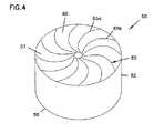
本発明に基づく汚染物質除去フィルタの第4の構成は、図4の50で示される。前の構成のように、フィルタ50は、第1面57と反対の第2面59とを有する基体52によって定められる。第1面57と第2面59との間の距離はフィルタ50の厚みである。基体52は一般にらせん状構造を形成するために構成された基板の多重の各シートによって形成される。例えば、基体52は、第1シート65a、隣接する第2シート65b、およびそれに続く各シートがある。これらのシート65は一般に平たんであるが、波形でもあり得る。65aと65bなどの隣接するシート65は一緒に、第1面57から第2面57に伸びる基体52を通る複数の通路60を定める。前の構成のように、フィルタ50は、円形あるいは非円形の断面を持つことができ、シート65の配置を容易にするためにコアを含むことができる。 A fourth configuration of the contaminant removal filter according to the present invention is shown at 50 in FIG. As in the previous configuration, the
本発明の汚染物質除去フィルタのための別の予期される構成は、多重の個々のシートによって形成される同心状の層を有するものである。 Another anticipated configuration for the contaminant removal filter of the present invention is to have concentric layers formed by multiple individual sheets.
汚染物質除去フィルタの特別な特徴は以下に記載される。容易なために、第1実施例のフィルタ10の参照番号だけが一般に使用されるが、特別に示されない場合、その特徴の記載はすべての構成に適用されることが理解される。 Special features of the contaminant removal filter are described below. For the sake of simplicity, only the reference numbers of the
フィルタの基体
基体12は汚染物質除去フィルタ10の総合的構造を提供し、基体12はフィルタ10の形状とサイズとを定める。基体12は立方体、円筒、円錐、切形の円錐、ピラミッド、切形のピラミッド、ディスクなどのいかなる3次元形状を持つことができる、しかしながら、第1面17および第2面19は、通路20に入ってくる流れが通路20から出る流れと等しいことを可能とするため、少なくとも同じ面積に近いものを有することが好ましい。第1面17、第2面19、面17と面19の間でえられる断面によって定められる基体12の断面の形状は、正方形、長方形、三角形、円、星、卵形、楕円、競馬場状、および同様のものなどのいかなる二次元形状でもあり得る。また、輪状形状もまた使用することができる。好ましくは、基体12の断面は、長さ「L」に沿って第1面17から第2面19まで本質的に一定である。The
通常、第1面17と第2面19は、少なくとも1cm2である、同じ面積を有する。追加のまたは代替の第1面17と第2面19は約1m2以下である面積を有する。多くの実施例では、面17と面19の面積は約70〜7500cm2である。フィルタ10の特別の応用では、その面積に対して好ましい範囲を有する。第1面17と第2面19の間である基体12の厚み「L」は通常少なくとも0.5cmであり、通常25cm以下である。多くの実施例では、「L」は約2〜10cmである。基体12の2つの特別な適切な厚みは2.5cmと7.5cmである。基体12の寸法は、フィルタ中のガスの滞流時間および結果としてガス流れからの汚染物質の除去に影響を与え得る。Usually, the
例えば、図1と2のエレメント10と10'を参照されるように、基体12には、通常、そこを通って伸びる複数の通路20を有する。通路20は、例えば、正方形、長方形、三角形、円形、台形、六角形(例えば、「ハニカム」)などのいかなる形状も持ち得るが、一般に好ましい形状は、図1で示されるようなドーム形である。好ましくは、通路20の形状は第1面17から第2面19まで変化が感知されず、フィルタ10中の各通路は同様の断面形状を有する。 For example, with reference to
各通路20は、一般に、通常約50mm2以下の断面積を有し、この断面積は少なくとも第1面17と第2面19の少なくとも1つと平行である。代替のまたは追加の通路20は通常約1mm2よりも小さくない断面積を有する。一般に、各通路20の断面積は約1.5〜30mm2、しばしば約2〜4mm2である。1つの好ましい実施例では、図1で例示される通路20などのドーム形通路20の断面積は約7〜8mm2である。別の好ましい実施例では、通路20の面積は1.9mm2である。Each
通路20の最も長い断面寸法は通常10mm以下、しばしば6mm以下である。さらに、通路20の最も短い断面寸法は0.25mm以上であり、しばしば1.5mm以上である。 The longest cross-sectional dimension of the
各細長い通路20の全内部表面積は、通常、約5mm2以上であり、通常約200cm2以下である。通路20の内部表面積によって定められるフィルタ10の総面積は少なくとも200cm2であり、あるいは約250cm2から約10m2である。The total internal surface area of each
第3の構成において、図3のエレメント30は層35の続く隣接する一巻きによって形成された単一の通路を持っている。そのような構成において、エレメント30の全内部表面積は少なくとも約200cm2であり、通常、約250cm2から10m2である。In the third configuration, the
通路20の形とサイズを定める通路壁は基体12を形成する基板によって定められる。基板は一般に、少なくとも0.015mmの厚さである。代替のあるいは追加の通路壁は一般に、5mm以下の厚さである。通常、通路壁は2mm以下の厚さである。壁の厚みは通路20のサイズ、基体12が作られる基板およびフィルタ10の使用用途によって変わり得る。層14と対面層16が通路20を定めるそれらの構成において、通路壁は層14と対面層16によって定められる。 The passage walls that define the shape and size of the
ほとんどの実施例において、各通路20はその長さに沿って連続したサイズと形状とを持っている。一般に、各通路20の長さは、第1面17と第2面19との間の厚み「L」として本質的に同じである。通路20は面17から面19まで直線でないことが予想される、しかしながら、このことは、通路20を通る圧力損失が望ましくないレベルの可能性をもつことによって、一般に好まれない。 In most embodiments, each
基体12(例えば、層14、16)は多孔性あるいは透過性基板で形成されるが、繊維状材料は好ましい材料である。基体12用の適切な基板の例は、天然の(例えば、セルロース材料)および高分子ベースの材料を含む。基板は、不織の繊維状材料(例えば、紡織され接着された)、織られた繊維状材料、編んだ繊維状材料、開いたまたは閉じたセルの発泡体またはスポンジ材料であり得る。適切な基板の特別な例は、グラス繊維紙、ちりめん紙、クラフト紙、羊毛、絹、セルロースの繊維織物(例えば、綿、リネン、ビスコースまたはレーヨンなど)および合成繊維の織物(例えば、ナイロン、ポリエステル、ポリエチレン、ポリプロピレン、ポリカーボネート、ポリビニルアルコール、アクリル、およびポリアミドなど)を含む。また、多孔性セラミック材料は基体12に使用され得る。 The substrate 12 (eg, layers 14 and 16) is formed of a porous or permeable substrate, although fibrous materials are the preferred materials. Examples of suitable substrates for the
基体12中の活性化された炭素繊維は、特に低濃度(約100ppm未満)のVOC除去のために望まれている。繊維は20wt%から100wt%のレベルで存在し得るが、30〜80wt%のレベルが最も一般的である。活性化された炭素繊維は一般に、基体12を形成するために他の少なくとも1つの繊維と混合されるが、熱可塑性繊維との組み合わせが好まれる。熱可塑性繊維は材料に強度と堅さを加える。炭素繊維は層14、16の一方あるいは両方に存在し得る。 Activated carbon fibers in
VOC除去のための基体12での使用に適した活性化された炭素繊維は、通常、約800〜3000m2/gの名目上のBET表面積、約0.3〜0.8cm3/gの細孔容積、5〜100μmの繊維直径、および0.1〜10mmの平均繊維長さを有する。Activated carbon fibers suitable for use in the
基体12に使用される材料は、基体12上に存在している活性材料(すなわち、酸性、塩基性、または他の反応材料)の機能に影響を与え得る、有害なオフガスあるいは汚染物質の放出を発生させるべきでない。好ましくは避けられる材料の例は、オフガスをする接着剤および他のそのような材料である。ある応用において許容される接着剤があり、接着剤はその応用に対して有害でなくかつ許容できるオフガスのレベル、量およびタイプを有する。 The material used for the
基体12のための好ましい基板は、セルロース繊維と結合した熱可塑性高分子繊維を有する。2つの繊維は、均一に結合され混合されてシート状の基板に形成され得る。加熱時に高分子繊維は軟化し、少なくとも部分的に溶融し、繊維は一緒に結合する。冷却のときに、高分子繊維は再び固化する熱可塑性材料を含む基板を使用すると、接着剤を使用せずに基板の多重シートあるいは層の接合を可能とする。適切な基板の特別の例は、ポリエチレンテレフタレート(PET)繊維を約40wt%とセルロース繊維を約60wt%有する。適切な基板の別の特別の例は、活性化された炭素繊維を約60wt%とポリエステル繊維を約40wt%有する。また、熱可塑性および非熱可塑性繊維の他の組み合わせもまた適切であろう。 A preferred substrate for the
図2で例示したような好ましい基体12の例は、セルロース繊維と結合した熱可塑性高分子繊維をどちらも有する、波形状シート14と対面シート16とからを作ることができる。シート14、16は、シートを局所的に加熱するために超音波を使用する超音波溶接機を通過され得る。圧力はシート14、16が互いに接触する領域に加えられ、その結果、シート14、16は一緒に結合する。また、活性化された炭素繊維と熱可塑性高分子繊維で作られたシート14、16は、そのような方法で溶接することができる。 An example of a
波形状シート14と対面シート16から基体12を作るための方法は、例えば、米国特許第6,416,605号および国際特許出願第WO 03/47722号に教授され、参照により本明細書に合体される。基体12はフィルタ10を通過する空気あるいは他のガス状流体から汚染物質を除去する酸性材料のための担体である。 Methods for making
上記で提供されたように、汚染物質除去フィルタ10は、塩基、酸、およびカルボニル含有化合物の除去のためにそれぞれ選択された酸性材料、塩基性またはアルカリ性材料、または反応材料などの活性材料を少なくとも1つ含む。汚染物質除去フィルタ10は、代替のまたは追加の、VOC除去用に基体12中に活性化された炭素繊維を含むことができる。 As provided above, the
活性材料は、基体12中の繊維としてよりはむしろ基体12中および基体上に提供された活性材料を有するフィルタ10を製造するために、液体キャリア中供給され、汚染物質除去フィルタを形成する基板上または基板中に含浸される。通常および好ましくは、活性材料は溶液の形態で基板中に含浸される。いくつかの材料は溶媒に溶解せずにむしろ分散されることが理解される。水は、溶液、分散体または他の混合物形態に対する好ましい溶媒である。 The active material is supplied in a liquid carrier to produce a
含浸溶液内の活性材料のレベルは特別な活性材料と使用される基板に基づいて選択される。溶液中の活性材料の量は、少なくとも約0.5wt%であり、約75wt%以下である。好ましくは、活性材料の量は、5-50wt%あるいは10-50wt%である。 The level of active material in the impregnation solution is selected based on the particular active material and the substrate used. The amount of active material in the solution is at least about 0.5 wt% and no more than about 75 wt%. Preferably, the amount of active material is 5-50 wt% or 10-50 wt%.
用語「含浸」「含浸する」およびその同類が使用されるが、基板への活性材料の適用方法が含浸に制限されないのは理解されるべきである。他の方法は、活性材料を基板に供給するのに使用され得る。活性材料を基板中に適用するために使用される他の代替の適切な方法は、浸漬、噴霧、ブラッシング、ナイフコーティング、キスコーティング、および表面または基板上に液体を適用するために知られている他の方法を含む。含浸または他の応用方法は、大気圧条件で、または、加圧または真空でなされ得る。 Although the terms “impregnation”, “impregnate” and the like are used, it should be understood that the method of applying the active material to the substrate is not limited to impregnation. Other methods can be used to supply the active material to the substrate. Other alternative suitable methods used to apply the active material into the substrate are known for dipping, spraying, brushing, knife coating, kiss coating, and applying a liquid on a surface or substrate Including other methods. Impregnation or other application methods can be done at atmospheric pressure conditions, or under pressure or vacuum.
好ましい方法では、基板は活性材料の適用前に基体12中に形成される。しかしながら、基板が基体12中に形成された後で基体12を形成され得ることは理解される。基体12中に活性化された炭素繊維を含ませるために、基板がその中を繊維で形成され得ることが理解される。 In a preferred method, the substrate is formed in the
含浸させられた後に、基板は少なくとも部分的に溶媒(例えば、水)を除去するために乾燥され、基板中および基板上には活性材料が残る。好ましくは、少なくとも90%の全自由水または他の溶媒が除去され、最も好ましくは、少なくとも95%の全自由水または他の溶媒が除去される。 After being impregnated, the substrate is dried to at least partially remove solvent (eg, water), leaving the active material in and on the substrate. Preferably, at least 90% total free water or other solvent is removed, and most preferably at least 95% total free water or other solvent is removed.
活性材料はエレメントの通路20の表面積の少なくとも50%の上および内部に存在している。好ましくは、活性材料は、通路壁の表面の少なくとも50%〜75%の上および内部に、より好ましくは表面の少なくとも90%で、最も好ましくは活性材料がない領域がなくて連続して全面的に接触している。活性材料は基板の厚みの少なくとも10%を通って存在している。好ましくは、活性材料は基板の少なくとも50%を通して、より好ましくは少なくとも80%を通って存在している。活性材料が基板中の活性化された炭素繊維であるときに、基板は、少なくとも30wt%の活性化された炭素繊維、好ましくは少なくとも60wt%の活性化された炭素繊維が均一に層14または層16中に分布されていることが好ましい。いくつかの実施例では、層14、16のうちの1つだけが活性化された炭素繊維を含む。 The active material is present above and within at least 50% of the surface area of the
活性材料は通常、基板の厚みを通常増加させない。しかしながら、活性材料は、基板の特性を変更し得る、例えば、基板をより堅くするまたはより柔軟にする。 The active material usually does not normally increase the thickness of the substrate. However, the active material can change the properties of the substrate, for example making the substrate stiffer or more flexible.
活性材料としての酸性材料
1つの設計では、汚染物質除去フィルタ10は活性材料として酸性材料を含む。酸性材料は、塩基性汚染物質と反応することによってまたは塩基性汚染物質を除去することによって通路を通り抜ける空気から汚染物質を除去する。Acidic Material as the Active Material In one design, the
本発明のエレメントでの使用のために適切な酸性材料の例は、クエン酸、蓚酸、マロン酸、高次の同族体等のカルボン酸(一、二、三、多酸;線形の、分岐した、および周期的な形態)、芳香族カルボン酸、スルフォン酸(線形の、周期的、芳香族)、硫酸、燐酸、硝酸、塩酸などの無機酸、ヘテロポリ酸(「超酸」)を含む。クエン酸は好ましい酸性材料である。 Examples of acidic materials suitable for use in the elements of the present invention include carboxylic acids (one, two, three, polyacids; linear, branched, etc., such as citric acid, succinic acid, malonic acid, higher homologues, etc. And periodic forms), aromatic carboxylic acids, sulfonic acids (linear, periodic, aromatic), inorganic acids such as sulfuric acid, phosphoric acid, nitric acid, hydrochloric acid, heteropolyacids ("superacids"). Citric acid is a preferred acidic material.
含浸溶液中の酸性材料のレベルは、酸性材料と使用される基板に基づいて選択される。溶液中の酸性材料の量は、少なくとも約0.5wt%であり、約75wt%以下である。好ましくは、酸性材料の量は10-50wt%である。好ましい酸性材料であるクエン酸に対して、クエン酸の量は約10-50wt%、好ましくは15-35wt%である。また、他の酸のレベルもまた適切であり得える。 The level of acidic material in the impregnation solution is selected based on the acidic material and the substrate used. The amount of acidic material in the solution is at least about 0.5 wt% and no more than about 75 wt%. Preferably, the amount of acidic material is 10-50 wt%. For the preferred acidic material, citric acid, the amount of citric acid is about 10-50 wt%, preferably 15-35 wt%. Other acid levels may also be appropriate.
低濃度の酸性材料が高濃度の酸性材料よりも一般に好まれることが見いだされた。例えば、5-15wt%のクエン酸を有する溶液は20-35wt%のクエン酸を有する溶液よりも好ましい。特別の例では、基板を5%の水性クエン酸溶液で含浸し、基板を乾燥し、次に、25%のクエン酸溶液を用いる一工程の含浸より、より良い塩基性汚染物質除去を提供する12%の水性クエン酸溶液で含浸する。この低濃度の2ステップ含浸工程は1ステップの含浸工程よりも好ましい。 It has been found that low concentrations of acidic materials are generally preferred over high concentrations of acidic materials. For example, a solution with 5-15 wt% citric acid is preferred over a solution with 20-35 wt% citric acid. In a specific example, the substrate is impregnated with a 5% aqueous citric acid solution, the substrate is dried, and then provides better basic contaminant removal than a one-step impregnation using a 25% citric acid solution. Impregnate with 12% aqueous citric acid solution. This low concentration two-step impregnation step is preferable to the one-step impregnation step.
酸性材料が活性材料の場合に避けるべき助剤
基板中の水分レベルの増加は酸で含浸させられたエレメントの適切な寿命を低下することが理論づけられる。したがって、乾燥された基板の水分含有量を増加する湿潤剤の使用は好ましくない。避けられるべき湿潤剤の例は、尿素、グリセロール、グリセリン、アルコール、ポリビニルピリジン、ポリビニルピロリドン、ポリビニルアルコール、ポリアクリレート、ポリエチレングリコール、およびセルロースアセテートを含む。また、乾燥された基板の水分含有量を増加する有機アミンの使用は好ましくない。避けられるべき有機アミンの例は、アルカノールアミン、ヒドロキシアミン、およびポリアミンを含む。It is theorized that increasing the moisture level in theauxiliary substrate tobe avoided when the acidic material is the active material reduces the proper lifetime of the element impregnated with acid. Therefore, the use of a wetting agent that increases the moisture content of the dried substrate is not preferred. Examples of wetting agents to be avoided include urea, glycerol, glycerin, alcohol, polyvinyl pyridine, polyvinyl pyrrolidone, polyvinyl alcohol, polyacrylate, polyethylene glycol, and cellulose acetate. Also, the use of organic amines that increase the moisture content of the dried substrate is not preferred. Examples of organic amines to be avoided include alkanolamines, hydroxyamines, and polyamines.
酸性材料が活性材料の場合に受け入れ可能な助剤
理論によって縛られないが出願人は、フィルタエレメントの基板中に存在する水分が、フィルタ上のかび、バクテリア、ウイルスなどの微生物の成長を容易にし、この微生物が酸性材料と反応するまたそうでない場合は劣化させると信じている。出願人は、酸性材料に少なくとも1つの防腐剤あるいは安定剤を加えるとエレメントの寿命に対する酸性材料の有効性を改良し、フィルタエレメントの寿命を伸ばすることを見出した。Although not bound by the adjunct theorythat is acceptable when the acidic material is an active material, Applicants believe that moisture present in the substrate of the filter element facilitates the growth of fungi, bacteria, viruses and other microorganisms on the filter. We believe that this microorganism reacts with acidic materials and otherwise degrades. Applicants have found that adding at least one preservative or stabilizer to the acidic material improves the effectiveness of the acidic material for the lifetime of the element and extends the lifetime of the filter element.
含浸溶液中の安定剤および/または防腐剤のレベルは、酸性材料と使用される安定剤または防腐剤に基づいて選択される。溶液中の安定剤および/又は防腐剤の量は少なくとも約0.01wt%であり、約20wt%以下である。好ましくは、安定剤および/又は防腐剤の量は、添加物に依存するが、0.1−10wt%、より好ましくは約0.1−10wt%、である。安定剤および/又は防腐剤の他のレベルもまた適切であり得る。 The level of stabilizer and / or preservative in the impregnation solution is selected based on the stabilizer or preservative used with the acidic material. The amount of stabilizer and / or preservative in the solution is at least about 0.01 wt% and not more than about 20 wt%. Preferably, the amount of stabilizer and / or preservative is 0.1-10 wt%, more preferably about 0.1-10 wt%, depending on the additive. Other levels of stabilizers and / or preservatives may also be appropriate.
適切な安定剤の例は、ポリアクリル酸である。溶液中のポリアクリル酸の好ましいレベルは、もし存在する場合は、約1−10wt%、好ましくは6−10wt%である。これらのレベルは特に酸性材料がクエン酸の場合に適切である。ポリアクリル酸の好ましいレベルは、クエン酸との比率として1:1〜約1:10、より好ましくは約1:2〜1:4である。 An example of a suitable stabilizer is polyacrylic acid. The preferred level of polyacrylic acid in the solution, if present, is about 1-10 wt%, preferably 6-10 wt%. These levels are particularly appropriate when the acidic material is citric acid. The preferred level of polyacrylic acid is 1: 1 to about 1:10, more preferably about 1: 2 to 1: 4 as a ratio to citric acid.
適切な防腐剤の例は、安息香酸、安息香酸ナトリウム、硝酸カリウム、亜硝酸カリウム、亜硝酸ナトリウム、硝酸ナトリウム、メチルパラベン、エチルパラベン、プロピルパラベン、ブチルパラベン、プロピオン酸、プロピオン酸ナトリウム、プロピオン酸カルシウム、ソルビン酸、ソルビン酸カリウム、酢酸、燐酸、ソルビン酸ナトリウム、ソルビン酸カルシウム、安息香酸カリウム、安息香酸カルシウム、エチルパラ-ヒドロキシ安息香酸、エチルパラ-ヒドロキシ安息香酸ナトリウム、プロピルパラヒドロキシ安息香酸、ビフェニル、ジフェニル、オルトフェニルフェノール、ナトリウムオルトフェニルフェノール、亜硫酸ナトリウム、硫酸ナトリウムを含む。溶液中の安息香酸ナトリウムの好ましいレベルは、存在する場合は、約0.01−5wt%、好ましくは0.1−1wt%、およびさらに好ましくは、約0.1−0.5wt%である。これらのレベルは特に酸性材料がクエン酸材料の場合は適切である。安息香酸ナトリウムが好ましいレベルは、クエン酸との比率として、約1:5から1:1000であり、より好ましくは、約1:50から1:700である。 Examples of suitable preservatives are benzoic acid, sodium benzoate, potassium nitrate, potassium nitrite, sodium nitrite, sodium nitrate, methyl paraben, ethyl paraben, propyl paraben, butyl paraben, propionic acid, sodium propionate, calcium propionate, sorbine Acid, potassium sorbate, acetic acid, phosphoric acid, sodium sorbate, calcium sorbate, potassium benzoate, calcium benzoate, ethyl para-hydroxybenzoic acid, sodium ethyl para-hydroxybenzoate, propyl parahydroxybenzoic acid, biphenyl, diphenyl, ortho Contains phenylphenol, sodium orthophenylphenol, sodium sulfite, sodium sulfate. The preferred level of sodium benzoate in the solution, if present, is about 0.01-5 wt%, preferably 0.1-1 wt%, and more preferably about 0.1-0.5 wt%. These levels are particularly appropriate when the acidic material is a citric acid material. A preferred level of sodium benzoate is about 1: 5 to 1: 1000, more preferably about 1:50 to 1: 700 as a ratio to citric acid.
活性材料としてのアルカリ性または塩基性材料
別の設計では、汚染物質除去フィルタ10は活性材料として塩基性材料を含む。塩基性材料は、酸性汚染物質と反応するあるいは別の方法で除去することによって、通路を通る空気から酸性汚染物質を除去する。In an alternative designof alkaline or basic material as the active material , the
本発明のエレメント中で使用するのための適切な塩基性材料の例は、炭酸塩、重炭酸塩、水酸化物、第4アンモニウム化合物(一般に水酸化物形態)などの塩基性塩、酸化銅、酸化マンガン、および酸化鉄などの金属酸化物を含む。ポリスチレン第4アンモニウム(水酸化物形態)、ポリスチレン第三アミン、グラフトされたポリエチレンを含むなどのイオン交換樹脂もまた塩基性汚染物質の除去に対して適切である。アルカリおよびアルカリ土類金属の塩基性塩、通常、リチウム、ナトリウム、およびカリウム塩が使用される。炭酸カリウムは汚染物質除去エレメント10における使用のための好ましい塩基性材料である。他の好ましい塩基性材料の例は重炭酸カリウム、炭酸ソーダ、および重炭酸ナトリウムを含む。 Examples of suitable basic materials for use in the elements of the present invention are basic salts such as carbonates, bicarbonates, hydroxides, quaternary ammonium compounds (generally hydroxide forms), copper oxides Metal oxides such as manganese oxide and iron oxide. Ion exchange resins such as those containing polystyrene quaternary ammonium (hydroxide form), polystyrene tertiary amine, grafted polyethylene, etc. are also suitable for the removal of basic contaminants. Basic salts of alkali and alkaline earth metals, usually lithium, sodium and potassium salts are used. Potassium carbonate is a preferred basic material for use in the
含浸溶液中の塩基性材料のレベルは、塩基性材料と使用される基板に基づいて選択される。溶液中の塩基性材料の量は少なくとも約0.5wt%であり、約75wt%以下である。好ましくは、塩基性材料の量は10−50wt-%である。好ましい塩基性材料が炭酸カリウムの場合、その量は約10−50wt%、好ましくは15−35wt%である。また、塩基性材料の他のレベルもまた適切である。 The level of basic material in the impregnation solution is selected based on the basic material and the substrate used. The amount of basic material in the solution is at least about 0.5 wt% and not more than about 75 wt%. Preferably, the amount of basic material is 10-50 wt-%. When the preferred basic material is potassium carbonate, the amount is about 10-50 wt%, preferably 15-35 wt%. Also other levels of basic material are suitable.
アルカリ材料が活性材料の場合に避けるべき助剤
基板中の水分レベルの増加はエレメントの適切な寿命を低下することが理論づけられる。したがって、乾燥された基板の水分含有量を増加する湿潤剤の使用は好ましくない。避けられるべき湿潤剤の例は、尿素、グリセロール、グリセリン、アルコール、ポリビニルピリジン、ポリビニルピロリドン、ポリビニルアルコール、ポリアクリレート、ポリエチレングリコール、およびセルロースアセテートを含む。また、乾燥された基板の水分含有量を増加する有機アミンの使用は好ましくない。避けられるべき有機アミンの例は、アルカノールアミン、ヒドロキシアミン、およびポリアミンを含む。It is theorized that increasing the moisture level in theauxiliary substrate tobe avoided when the alkaline material is an active material reduces the proper lifetime of the element. Therefore, the use of a wetting agent that increases the moisture content of the dried substrate is not preferred. Examples of wetting agents to be avoided include urea, glycerol, glycerin, alcohol, polyvinyl pyridine, polyvinyl pyrrolidone, polyvinyl alcohol, polyacrylate, polyethylene glycol, and cellulose acetate. Also, the use of organic amines that increase the moisture content of the dried substrate is not preferred. Examples of organic amines to be avoided include alkanolamines, hydroxyamines, and polyamines.
アルカリ材料が活性材料の場合に受け入れ可能な助剤
出願人は、塩基性またはアルカリ性材料に助触媒を加えると、エレメントの寿命に対して塩基性あるいはアルカリ性材料の有効性が改良されて、フィルタエレメントの寿命を伸ばすことを見出した。Applicants who areacceptable auxiliaries when the alkaline material is an active material have found that adding a cocatalyst to a basic or alkaline material improves the effectiveness of the basic or alkaline material with respect to the lifetime of the element, so Found to extend the lifespan.
含浸溶液中の助触媒のレベルは、塩基性材料と使用される助触媒に基づいて選択される。適切な助触媒の例は、ヨウ化カリウム、ヨウ化ナトリウム、ヨウ化リチウム、ヨウ素酸カリウム、ヨウ素酸ナトリウム、またはヨウ素酸リチウムである。好ましい助触媒はヨウ化カリウムであり、この助触媒は特に炭酸カリウム材料とともの使用に適している。 The level of promoter in the impregnation solution is selected based on the basic material and the promoter used. Examples of suitable promoters are potassium iodide, sodium iodide, lithium iodide, potassium iodate, sodium iodate, or lithium iodate. A preferred cocatalyst is potassium iodide, which is particularly suitable for use with potassium carbonate materials.
溶液中の助触媒の量は少なくとも約0.01wt%であり、約20wt%以下である。好ましくは、助触媒の量は0.1−10wt%、より好ましくは、約0.1−5wt%である。これらのレベルは塩基性材料が約5wt%であるときに、特に適切である。また、助触媒の他のレベルも適切であろう。好ましいレベルの助触媒は、塩基性材料の比率として、約1:1から1:50であり、より好ましくは約1:3から1:10である。 The amount of cocatalyst in the solution is at least about 0.01 wt% and no more than about 20 wt%. Preferably, the amount of promoter is 0.1-10 wt%, more preferably about 0.1-5 wt%. These levels are particularly appropriate when the basic material is about 5 wt%. Other levels of cocatalyst may also be appropriate. A preferred level of cocatalyst is from about 1: 1 to 1:50, more preferably from about 1: 3 to 1:10, as a ratio of basic material.
活性材料としての反応物材料
別の設計では、汚染物質除去フィルタ10は活性材料として反応物材料を含む。反応物材料は、カルボニル含有化合物と反応するあるいは別の方法で除去することによって通路を通る空気からカルボニル含有化合物を除去する。In another designof reactant material as the active material , the
本発明のフィルタエレメントで使用するのための適切な反応物材料の例は、亜硫酸塩、重亜硫酸塩、酸化剤、アンモニア誘導体、特に高分子量の安定したアミンを含む。アルデヒドの除去のために、強アルカリ(塩基性)材料が好まれる。 Examples of suitable reactant materials for use in the filter element of the present invention include sulfites, bisulfites, oxidants, ammonia derivatives, especially high molecular weight stable amines. For the removal of aldehydes, strongly alkaline (basic) materials are preferred.
より特別の例の適切な反応物は、亜硫酸塩に対して亜硫酸ナトリウムおよび亜硫酸カリウム、重亜硫酸塩に対して、重亜硫酸ナトリウムと重亜硫酸カリウム、アンモニア誘導体に対して、特別に適切な高分子量と安定したアミン、2、4ジニトロフェニルヒドラジン(DNPH)、2-ヒドロキシメチルピペリジン(2-HMP)、およびトリス(ヒドロキシメチル)アミノメタン、強アルカリに対して水酸化ナトリウムおよび水酸化カリウムを含む。カルボニル含有化合物除去方法の様々な例は以下に提供される。 Suitable reactants in more specific examples include sodium sulfite and potassium sulfite for sulfites, sodium bisulfite and potassium bisulfite for ammonia bisulphite, and particularly suitable high molecular weights for ammonia derivatives. Stable amines, 2, 4 dinitrophenylhydrazine (DNPH), 2-hydroxymethylpiperidine (2-HMP), and tris (hydroxymethyl) aminomethane, sodium hydroxide and potassium hydroxide against strong alkali. Various examples of carbonyl-containing compound removal methods are provided below.
カルボニル含有化合物と亜硫酸塩の反応例は以下の通りである。
RCR’O+Na2SO3+H2O→NaOH+HORCR’SO3Na
カルボニル含有化合物との重亜硫酸塩の反応例は以下の通りである。
RCR’O+NaHSO3→HORCR’SO3NaExamples of the reaction of the carbonyl-containing compound and sulfite are as follows.
RCR′O + Na2 SO3 + H2 O → NaOH + HORCR′SO3 Na
An example of the reaction of bisulfite with a carbonyl-containing compound is as follows.
RCR'O + NaHSO3 → HORCR'SO3 Na
アルデヒドと高分子量で安定したアミンの反応例は以下の通りである。
HCHO+NH2−R→HCNH−R+H2OExamples of the reaction of aldehydes with high molecular weight stable amines are as follows.
HCHO + NH2 −R → HCNH—R + H2 O
アルデヒドと強アルカリの反応例は以下の通りである。
2RCHO+NaOH→RCOONa+RCH2OHExamples of the reaction between aldehyde and strong alkali are as follows.
2RCHO + NaOH → RCONa + RCH2 OH
含浸溶液中の反応物材料のレベルは反応物材料と使用される基板に基づいて選択される。溶液中の反応物材料の量は少なくとも約0.5wt%であり、約75wt%以下である。好ましくは、反応物の材料の量は5-50wt%である。例えば、トリス(ヒドロキシメチル)アミノメタンが使用される場合、好ましいレベルは含浸溶液で約5wt%である。水酸化ナトリウムが使用される場合、好ましいレベルは約5wt%である。また、10−50wt%などの他の反応物材料のレベルも適切である。 The level of reactant material in the impregnation solution is selected based on the reactant material and the substrate used. The amount of reactant material in the solution is at least about 0.5 wt% and no more than about 75 wt%. Preferably, the amount of reactant material is 5-50 wt%. For example, when tris (hydroxymethyl) aminomethane is used, the preferred level is about 5 wt% in the impregnation solution. When sodium hydroxide is used, the preferred level is about 5 wt%. Other reactant material levels such as 10-50 wt% are also suitable.
避けられるべき添加物
基板中の水分レベルの増加はエレメントの適切な寿命を低下することが理論づけられる。したがって、乾燥された基板の水分含有量を増加する湿潤剤の使用は好ましくない。避けられるべき湿潤剤の例は、尿素、グリセロール、グリセリン、アルコール、ポリビニルピリジン、ポリビニルピロリドン、ポリビニルアルコール、ポリアクリレート、ポリエチレングリコール、およびセルロースアセテートを含む。It is theorized that increasing the moisture level in theadditive substrateto be avoided reduces the proper lifetime of the element. Therefore, the use of a wetting agent that increases the moisture content of the dried substrate is not preferred. Examples of wetting agents to be avoided include urea, glycerol, glycerin, alcohol, polyvinyl pyridine, polyvinyl pyrrolidone, polyvinyl alcohol, polyacrylate, polyethylene glycol, and cellulose acetate.
上記記載された活性材料は、いずれも活性化された炭素繊維に含浸させるかまたは別の方法で適用することができる。 Any of the active materials described above can be impregnated into activated carbon fibers or otherwise applied.
再生
本発明の汚染物質除去フィルタでは、酸性、塩基性、または反応材料を有するか否かに関係なく再生することができることを見出した。使用の後または長期間使用しなかった後に、酸性材料、アルカリ性材料、または反応物材料で再びエレメントを含浸することができる。この第2あるいはその後の含浸は、例えば、水のすすぎによってフィルタから前の汚染物質を洗浄する、洗浄しないにかかわらずすることができる。基板が物理的に損なわれないという制限で、基板は何回でも含浸することができることが予想される。Regeneration It has been found that the contaminant removal filter of the present invention can be regenerated regardless of whether it has acidic, basic, or reactive materials. After use or after long periods of non-use, the element can be impregnated again with acidic, alkaline, or reactant materials. This second or subsequent impregnation can be done with or without washing the previous contaminant from the filter, for example by rinsing with water. It is expected that the substrate can be impregnated any number of times, with the limitation that the substrate is not physically damaged.
汚染物質除去フィルタ10のための応用
本発明の汚染物質除去フィルタ10は、空気流れなどのガス流れから汚染物質除去を望むいかなる種類の応用にも使用することができる。汚染物質除去フィルタ10は特に、ガスから1ppm未満の汚染物質のレベルまで化学汚染物質の除去を望む高純度の応用に対して適している。多くの高純度の応用において、望まれているレベルは1ppb未満の汚染物質である。一般に、フィルタ10自体はオフガスなどによっていかなる汚染物質も追加しない。Applications for the
酸を含浸したフィルタ10によって除去され得る、共通の、空気で運ばれる塩基性汚染物質化合物の例は、アンモニア、アミン、アミド、N−メチルl−1,2−ピロロドン、水酸化ナトリウム、水酸化リチウム、水酸化カリウム、揮発性の有機塩基および不揮発性の有機塩基などの有機塩基を含む。アルカリを含浸したフィルタ10によって除去され得る、共通の、空気で運ばれる酸性汚染物質化合物の例は、酸化硫黄、酸化窒素、HCl(塩酸)、HNO3(硝酸)、H2S(硫化水素)、H2SO4(硫酸)およびHCN(シアン化水素)を含む。共通の空気で運ばれるカルボニル含有化合物の例は、アセトンを含むケトン、ホルムアルデヒドを含むアルデヒドを含む。カルボニル含有化合物は、一般に、かなり悪臭を放って、多くの人々に不快を引き起こす。人々の中にはカルボニル含有化合物にアレルギーの反応を持つ人もいる。Examples of common airborne basic pollutant compounds that can be removed by the acid impregnated
一般に、汚染物質除去フィルタ10は、充填された微粒状ベッドが使用されるような、石版印刷プロセス、半導体プロセス、写真画像プロセスおよび熱アブレーティブ画像プロセスを含むいかなる応用でも使用することができる。燃料電池の適切で効率的な操作は、容認できない塩基性汚染物質を含まない空気を取入ることによって利益を得るだろう。汚染物質除去フィルタ10を使用することができる他の応用は、人々がその空気を呼吸する利益のために環境空気が浄化されるような応用を含む。フィルタ10は、呼吸装置(慣用のものと動力を備えたものの療法)などの個人的装置と清浄な呼吸用空気を供給するための自給式呼吸装置とで使用することができる。汚染物質除去フィルタ10は、また大きいスケールで、例えば、住宅用および商業用空間(部屋とビル全体など)、飛行機の客室、および自動車の車室などの閉じられた空間で使用することができる。他の時に、空気を大気に放出する前に汚染物質を除去ことが望まれる。そのような応用の例は、自動車または他の乗り物からの放出、工業的操業からの排気、あるいは化学汚染物質を環境に放出するような他の操業または応用も含む。 In general, the
フィルタ10は通常、ガス流れ(例えば、空気の流れ)がフィルタ10の通路20に入って通過するように向けるハウジング、フレームまたは他の構造中に配置される。多くの構成において、フィルタ10は、ハウジング、フレームまたは他の構造によってその周囲の周りが少なくとも部分的に囲まれているる。 The
本明細書で記述されたプロセスで作られた汚染物質除去フィルタ10は、システム内に配置され、プレフィルタ、ポストフィルタまたは両方が汚染物質除去フィルタ10と協同して使用される。プレフィルタは、フィルタ10の上流に配置され、フィルタ10を使用する前に空気で運ばれる粒子を除去する。ポストフィルタは、フィルタ10の下流に配置され、空気が放出される前にフィルタ10から残留粒子を除去する。これらのフィルタは一般に、汚染物質除去フィルタ10の第1面17と第2面19に対向してあるいは近くに近接してそれぞれ配置される。プレフィルタを含むシステムの例は図5に示される。 A
図5では、システム100は、汚れたガス流れ101から汚染物質を除去ために示される。システム100は微粒子フィルタ105、第1の汚染物質除去フィルタ110、および第2の汚染物質除去フィルタ110'を含む。微粒子フィルタ105は、ガス流れ101からほこりと煙などの固体粒子を除去ために構成される。通常、微粒子フィルタ105が使用される場合は、微粒子フィルタ105は、汚染物質除去フィルタ110と110’の上流に配置され、汚染物質除去フィルタ110、110'が微粒子で詰まらされるまたは積み込まれるのを低減する。1つの例では、第1汚染物質除去フィルタ110はガス流れ101から塩基性汚染物質を除去ために構成され、第2汚染物質除去フィルタ110'は、ガスの流れ101から酸性汚染物質を除去ために構成される。代替の実施例において、酸性汚染物質、塩基性汚染物質、またはカルボニル含有化合物を除去ための形態でフィルタ110、110'を構成することができることが理解される。微粒子フィルタ105、汚染物質除去フィルタ110、および汚染物質除去フィルタで110'をそれぞれ通過した後の結果としての浄化されたガス流れは102として示される。 In FIG. 5, the
微粒子フィルタ105、フィルタ110、およびフィルタ110'のいずれあるいはすべてはハウジング120などのハウジング中に保有され得る。フィルタ105、110、110'は互いに隣接して置かれるまたはその間に空間を有するかもしれない。 Any or all of the
塩基汚染物質除去フィルタと微粒子フィルタが結合した代替の構成は、フィルタ70として図6で例証される。汚染物質除去フィルタ70は、第1面77と反対の第2面79を有する基体72によって定められる。一般に、汚染物質を浄化すべきガスは第1面77を通ってフィルタ70に入り、第2面を通って出る。基体72は図2のフィルタ10'の基体12と類似しており、波形状層74と対面層76とを交互に有する。層74と層76とは一緒に複数の通路80を定める。通路80の第1セットは第1面77でブロックされあるいはシールされる、これらはシール85として示される。シール85の反対の端、第2面79で、通路80は開いている。さらに、通路80の第2セットは、第2面79でブロックされあるいはシールされ、第1面77で開いている。 An alternative configuration in which a base contaminant removal filter and a particulate filter are combined is illustrated in FIG. The
使用中、微粒子が積み込まれたガスは第1面77の開いている通路80を入る。微粒子はシールされた第2面79によって通路80で捕集されるが、ガスは繊維状基板によって形成された通路壁を通り抜ける。基板中と基板上の活性材料は空気で運ばれる汚染物質を除去する。浄化されたガスは第2面を通って出る。 During use, the gas loaded with particulates enters an
フィルタ70は、Z−フィルタ、まっすぐに通る流れフィルタ、インラインフィルタとして言及される。フィルタ70としてのそのようなフィルタの微粒子を除去する特徴は、例えば、米国特許第5,820,646号、同第6,190,432号、同第6,350,291号に記載されている。
除去されずにフィルタ10を通り抜ける汚染物質の量を、もしある場合に、モニターするための表示計器または表示システムはフィルタ10あるいは他の実施例の下流に配置され得る。そのような表示計器はよく知られている。 A display instrument or system for monitoring, if any, the amount of contaminants that pass through the
フィルタ10の形状とサイズは、フィルタ10中のガスの滞留時間に基づいて、そこを通過するガスまたは空気から所望の量の汚染物質を除去ために選択される。例えば、好ましくは少なくとも90%、より好ましくは少なくとも95%の汚染物質が除去かれる。いくつかの設計では、汚染物質の98%またはそれ以上が除去される。除去かれるべき汚染物質の所望量は、用途、汚染物質の量および種類によって異なるのは理解される。例として、半導体処理施設に対し、フィルタ10に入って来る空気の滞留時間は通常約0.06〜0.36秒であり、それは、約7.6〜15cmの厚みを有するエレメントによって成し遂げることができる。 The shape and size of the
実施例
以下の限定無しの実施例はさらに本発明を例証するであろう。実施例におけるすべての部品、割合、比率は、別の方法で示されない限り、重量によって示される。Examples The following non-limiting examples will further illustrate the invention. All parts, proportions, ratios in the examples are given by weight unless otherwise indicated.
2つの異なった基体が実施例の汚染物質除去エレメントとして使用された。
基体1:
基体1は平たんな対面シートと折り曲げ状の波形状シートと交互にすることによって形成された図2のものと同様である。各シートは100%のセルロース繊維から作られた。シートは、シリンダを形成するために巻き付けられた。結果としてのドーム形の通路は、約3.4mmの高さと約5.0mmの幅を有した。各通路の断面積は約8.5mm2であった。シートはウレタン接着剤で結合された。Two different substrates were used as the contaminant removal element in the examples.
Base 1:
The
基体2:
基体2は、基体2が約1.05mmの高さと2.90mmの幅を有するのドーム形の通路を除いて基体1と類似であった。各通路の断面積は約1.5mm2だった。シートは60%のセルロース繊維と40%のPET繊維から作られた。シートは超音波エネルギーで生成した熱で溶融する熱可塑性材料によって結合された。Base 2:
The substrate 2 was similar to the
酸性が含浸された実施例
基体は以下の方法によって酸性材料で含浸された。酸性溶液の容積はビーカーに入れられた。基体全体が溶液中に浸漬されるように繊維状基体はビーカー中に配置された。約60秒後、基体は取り出され、1時間オーブン中で乾燥された。乾燥後、結果としてえられるフィルタエレメントは、その概算寿命を決定するために試験された。Example substratesimpregnated with acid were impregnated with acidic material in the following manner. The volume of acidic solution was placed in a beaker. The fibrous substrate was placed in a beaker so that the entire substrate was immersed in the solution. After about 60 seconds, the substrate was removed and dried in an oven for 1 hour. After drying, the resulting filter element was tested to determine its approximate life.
破過試験(breakthrough test)1
フィルタエレメントは、テストチャンバーに配置され、フィルタの上流側と下流側を提供するためにシールされた。50ppmのアンモニアを含んだ空気流れは、30リットル/分の流れ速度でフィルタエレメントの上流側に送られた。上流と川流のアンモニア濃度は、アンモニア検知器を使用してモニターされた。
The filter element was placed in the test chamber and sealed to provide the upstream and downstream sides of the filter. An air stream containing 50 ppm of ammonia was sent upstream of the filter element at a flow rate of 30 liters / minute. Upstream and river ammonia concentrations were monitored using ammonia detectors.
比較実施例A:
35wt%クエン酸の水溶液が作られた。約3.8cmの直径と約7.5cmの長さを有する基体1はこの水溶液で含浸された。比較実施例Aは破過試験1で試験されて、その結果は図7のグラフに示される。Comparative Example A:
An aqueous solution of 35 wt% citric acid was made. A
実施例1:
35wt%クエン酸と6wt%のポリアクリル酸の水溶液が作られた。約3.8cmの直径と約7.5cmの長さを有する基体1はこの水溶液で含浸された。実施例1は破過試験1で試験されて、その結果は図7のグラフに示される。Example 1:
An aqueous solution of 35 wt% citric acid and 6 wt% polyacrylic acid was made. A
実施例2:
35wt%クエン酸と1wt%のポリアクリル酸の水溶液が作られた。約3.8cmの直径と約7.5cmの長さを有する基体1はこの水溶液で含浸された。実施例2は破過試験1で試験されて、その結果は図7のグラフに示される。Example 2:
An aqueous solution of 35 wt% citric acid and 1 wt% polyacrylic acid was made. A
実施例3:
35wt%クエン酸と0.5wt%の安息香酸ナトリウムの水溶液が作られた。約3.8cmの直径と約7.5cmの長さを有する基体1はこの水溶液で含浸された。実施例3は破過試験1で試験されて、その結果は図7のグラフに示される。Example 3:
An aqueous solution of 35 wt% citric acid and 0.5 wt% sodium benzoate was made. A
図7は、時間とともに(X座標に沿って)、10%のしきい値に到達する時間が比較実施例Aと実施例2の両方で減少する、ただし実施例2は比較実施例Aと同じように早くはない、ことを示している。試験の持続時間に対して、実施例1と3は性能低下がないことを示している。 FIG. 7 shows that over time (along the X coordinate), the time to reach the 10% threshold decreases in both Comparative Example A and Example 2, except that Example 2 is the same as Comparative Example A. It shows that it is not so early. For the duration of the test, Examples 1 and 3 show no performance degradation.
比較実施例B:
15wt%クエン酸と15wt%尿素の水溶液が作られた。約3.8cmの直径と約7.5cmの長さを有する基体1はこの溶液で含浸された。比較実施例Bは破過試験1で試験されて、その結果は図8のグラフに示される。Comparative Example B:
An aqueous solution of 15 wt% citric acid and 15 wt% urea was made. A
実施例4:
15wt%クエン酸と10wt%のポリアクリル酸の水溶液が作られた。約3.8cmの直径と約7.5cmの長さを有する基体1はこの溶液で含浸された。実施例4は破過試験1で試験されて、その結果は図8のグラフに示される。Example 4:
An aqueous solution of 15 wt% citric acid and 10 wt% polyacrylic acid was made. A
図8は、時間とともに(X座標に沿って)、10%のしきい値に到達する時間が、湿潤剤を含んだ比較実施例Bで減少することを示している。試験の持続時間に対して、実施例4は性能低下がないことを示している。 FIG. 8 shows that over time (along the X coordinate), the time to reach the 10% threshold decreases in Comparative Example B with wetting agent. For the duration of the test, Example 4 shows no performance degradation.
実施例5
35wt%クエン酸と0.5wt%硫酸ナトリウムの水溶液が作られた。約3.8cmの直径と約2.5cmの長さを有する基体2はこの溶液で含浸された。実施例5は破過試験1で試験されて、その結果は図9のグラフに示される。Example 5
An aqueous solution of 35 wt% citric acid and 0.5 wt% sodium sulfate was made. A substrate 2 having a diameter of about 3.8 cm and a length of about 2.5 cm was impregnated with this solution. Example 5 was tested in
実施例6
35wt%クエン酸と0.5wt%安息香酸ナトリウムの水溶液が作られた。約3.8cmの直径と約2.5cmの長さを有する基体2はこの溶液で含浸された。実施例5は破過試験1で試験されて、その結果は図9のグラフで示される。Example 6
An aqueous solution of 35 wt% citric acid and 0.5 wt% sodium benzoate was made. A substrate 2 having a diameter of about 3.8 cm and a length of about 2.5 cm was impregnated with this solution. Example 5 was tested in
実施例7
50wt%クエン酸と0.5wt%の安息香酸ナトリウムの水溶液が作られた。約3.8cmの直径と約2.5cmの長さを有する基体2はこの溶液で含浸された。実施例7は破過試験1で試験されて、その結果は図9のグラフで示される。Example 7
An aqueous solution of 50 wt% citric acid and 0.5 wt% sodium benzoate was made. A substrate 2 having a diameter of about 3.8 cm and a length of about 2.5 cm was impregnated with this solution. Example 7 was tested in
実施例8
35wt%クエン酸と0.5wt%硫酸ナトリウムの水溶液が作られた。約3.8cmの直径と約2.5cmの長さを有する基体2はこの溶液で含浸された。実施例8は週末(約48時間)の間乾燥されて、次に、破過試験1に従って試験された。その結果は図9のグラフで例証される。Example 8
An aqueous solution of 35 wt% citric acid and 0.5 wt% sodium sulfate was made. A substrate 2 having a diameter of about 3.8 cm and a length of about 2.5 cm was impregnated with this solution. Example 8 was dried over the weekend (about 48 hours) and then tested according to
図9は、試験の持続する時間の間、実施例5、実施例6および実施例8が性能低下が無いことを示している。実施例7には、破過時間の増加があった。これは試験されたフィルタの小さい領域と同様に利用可能な試験データの小さい領域による可能性がある。3.8cmの直径で、フィルタの中心は損傷を受けて10%の破過時間における小さな変動を起こすが、総合的な能力は良い。 FIG. 9 shows that Example 5, Example 6 and Example 8 have no performance degradation for the duration of the test. In Example 7, there was an increase in breakthrough time. This may be due to the small area of available test data as well as the small area of the tested filter. At a diameter of 3.8 cm, the center of the filter is damaged causing a small variation in 10% breakthrough time, but the overall capability is good.
アルカリが含浸された実施例
基体は以下の方法によって塩基性材料で含浸された。塩基性溶液の容積はビーカーに入れられた。基体全体が溶液中に浸漬されるように繊維状基体はビーカー中に配置された。約60秒後、基体は取り出され、1時間オーブン中で乾燥された。乾燥後、結果としてえられるフィルタエレメントは、その概算寿命を決定するために試験された。フィルタエレメントは、テストチャンバーに配置され、フィルタの上流側と下流側を提供するためにシールされた。Example substratesimpregnated with alkali were impregnated with a basic material in the following manner. The volume of basic solution was placed in a beaker. The fibrous substrate was placed in a beaker so that the entire substrate was immersed in the solution. After about 60 seconds, the substrate was removed and dried in an oven for 1 hour. After drying, the resulting filter element was tested to determine its approximate life. The filter element was placed in the test chamber and sealed to provide the upstream and downstream sides of the filter.
破過試験2
破過試験2に対して、500ppbのSO2と50%相対湿度を含んだ空気流れは、30リットル/分の流れ速度でフィルタエレメントの上流側に送られた。上流側と川流側の亜硫酸ガス濃度は、SO2検出器を使用してモニターされた。Breakthrough test 2
For breakthrough test 2, an air flow containing 500 ppb SO2 and 50% relative humidity was sent upstream of the filter element at a flow rate of 30 liters / minute. The sulfur dioxide gas concentration on the upstream side and the river side was monitored using an SO2 detector.
破過試験3
破過試験3に対して、50ppmのSO2と50%の相対湿度を含んだ空気流れは30リットル/分の流れ速度でフィルタエレメントの上流側に送られた。上流側と川流側の亜硫酸ガス濃度は、SO2検出器を使用してモニターされた。Breakthrough test 3
For breakthrough test 3, an air stream containing 50 ppm SO2 and 50% relative humidity was sent upstream of the filter element at a flow rate of 30 liters / minute. The sulfur dioxide gas concentration on the upstream side and the river side was monitored using an SO2 detector.
比較実施例C:
20wt%炭酸カリウム(K2CO3)の水溶液が作られた。約3.8cmの直径と約7.5cmの長さを有する基体2はこの水溶液で含浸された。比較実施例Cは破過試験2で試験されて、その結果は図10のグラフで示される。Comparative Example C:
An aqueous solution of 20 wt% potassium carbonate (K2 CO3 ) was made. A substrate 2 having a diameter of about 3.8 cm and a length of about 7.5 cm was impregnated with this aqueous solution. Comparative Example C was tested in breakthrough test 2 and the results are shown in the graph of FIG.
比較実施例D:
20wt%のK2CO3の水溶液が作られた。約3.8cmの直径と約7.5cmの長さを有する基体2はこの溶液で含浸された。比較実施例Dは破過試験2で試験されて、その結果は図10のグラフで示される。Comparative Example D:
An aqueous solution of 20 wt% K2 CO3 was made. A substrate 2 having a diameter of about 3.8 cm and a length of about 7.5 cm was impregnated with this solution. Comparative Example D was tested in breakthrough test 2 and the results are shown in the graph of FIG.
実施例9
20wt%のK2CO3と6.6wt%のKIの水溶液が作られた。3.8cmの直径と約7.5cmの長さを有する基体2がこの溶液で含浸された。実施例9は、破過試験2で試験されて、その結果は図10のグラフで示される。Example 9
An aqueous solution of 20 wt% K2 CO3 and 6.6 wt% KI was made. A substrate 2 having a diameter of 3.8 cm and a length of about 7.5 cm was impregnated with this solution. Example 9 was tested in breakthrough test 2 and the results are shown in the graph of FIG.
図10は時間とともに試験されたフィルタエレメントを通り抜けるSO2レベルを示す。助触媒を含んだ実施例9は、比較実施例C、Dよりもより良いSO2除去を提供することがわかる。FIG. 10 shows the SO2 level through the filter element tested over time. It can be seen that Example 9 containing the cocatalyst provides better SO2 removal than Comparative Examples C and D.
比較実施例E:
20wt%のK2CO3の水溶液が作られた。約3.8cmの直径と約7.5cmの長さを有する基体2はこの溶液で含浸された。比較実施例Eは破過試験3で試験された。試験されたサンプルの写真は図12で示される。Comparative Example E:
An aqueous solution of 20 wt% K2 CO3 was made. A substrate 2 having a diameter of about 3.8 cm and a length of about 7.5 cm was impregnated with this solution. Comparative Example E was tested in breakthrough test 3. A photograph of the tested sample is shown in FIG.
実施例10
20wt%のK2CO3と6.6wt%のKIの水溶液が作られた。約3.8cmの直径と約7.5cmの長さを有する基体2はこの溶液で含浸された。実施例10は破過試験で試験された。試験されたサンプルの写真は図11で示される。Example 10
An aqueous solution of 20 wt% K2 CO3 and 6.6 wt% KI was made. A substrate 2 having a diameter of about 3.8 cm and a length of about 7.5 cm was impregnated with this solution. Example 10 was tested in a breakthrough test. A photograph of the tested sample is shown in FIG.
破過試験3からの比較実施例Eと実施例10の定量的な試験結果は、2つフィルタエレメント寿命が同様であることを示した。しかしながら、図11と図12の比較は、2つのサンプルが同じ量のSO2を吸着したがフィルタを横切る圧力損失において重要な違いがあることを示している。図12でわかるように、比較実施例Eの入口面にはかなりの材料の集積があって、その結果、それを通る空気流れのために利用できる容積を減少させる。比較実施例Eの入口側における結晶の集積K2SO3として同定された。この集積は図11の実施例10上では見られなかった。この集積は低濃度下での破過試験2では見られなかった。The quantitative test results of Comparative Example E and Example 10 from Breakthrough Test 3 showed that the two filter element lifetimes were similar. However, a comparison between FIG. 11 and FIG. 12 shows that the two samples adsorbed the same amount of SO2 but there is an important difference in the pressure drop across the filter. As can be seen in FIG. 12, there is considerable material accumulation at the inlet surface of Comparative Example E, thereby reducing the volume available for air flow therethrough. It was identified as the crystal accumulation K2 SO3 on the inlet side of Comparative Example E. This accumulation was not seen on Example 10 of FIG. This accumulation was not seen in breakthrough test 2 at low concentrations.
反応物が含浸された例
基体は以下の方法により反応物材料で含浸された。反応物溶液の体積はビーカーに入れられた。基体全体が溶液中に浸漬されるように繊維状基体はビーカー中に配置された。約60秒後、基体は取り出され、1時間オーブン中で乾燥された。Example impregnated with reactants The substrate was impregnated with reactant materials in the following manner. The volume of the reactant solution was placed in a beaker. The fibrous substrate was placed in a beaker so that the entire substrate was immersed in the solution. After about 60 seconds, the substrate was removed and dried in an oven for 1 hour.
乾燥後、結果としてのフィルタエレメントは、その概算寿命を決定するためにテストされた。 After drying, the resulting filter element was tested to determine its approximate life.
破過試験4
破過試験4に対して、フィルタエレメントは、テストチャンバーに配置され、フィルタの上流側と下流側を提供するためにシールされた。0.7ppmのホルムアルデヒドと50%の相対湿度を含んだ空気流れは、30リットル/分の流れ速度でフィルタエレメントの上流側に送られた。フィルタエレメントは、約3.8cmの直径と約2.54cmの長さを有した。川流側のホルムアルデヒド濃度は、検出器を使用してモニターされた。Breakthrough test 4
For breakthrough test 4, the filter element was placed in the test chamber and sealed to provide the upstream and downstream sides of the filter. An air stream containing 0.7 ppm formaldehyde and 50% relative humidity was sent upstream of the filter element at a flow rate of 30 liters / minute. The filter element had a diameter of about 3.8 cm and a length of about 2.54 cm. The streamside formaldehyde concentration was monitored using a detector.
比較実施例 F
基体1から、約3.8cmの直径と約2.54cmの長さを有するフィルタエレメントが作られた。基体基板の表面または基板処理はなかった。Comparative Example F
A filter element having a diameter of about 3.8 cm and a length of about 2.54 cm was made from the
実施例11
トリス(ヒドロキシメチル)アミノメタンの5%水溶液が作られた。約3.8cmの直径と約2.54cmの長さを有する基体1はこの溶液で含浸された。Example 11
A 5% aqueous solution of tris (hydroxymethyl) aminomethane was made. A
実施例11と比較実施例Fは、破過試験4によって試験され、その結果が図13で示される。図13のグラフは、含浸されたフィルタエレメントの実施例11が劇的に寿命が伸びることを示している。ホルムアルデヒドのレベルは、比較実施例Fでは直ちに0.5ppmに達するが、実施例11では0.5ppmに達するのに少なくとも5000分有した。 Example 11 and Comparative Example F were tested by breakthrough test 4 and the results are shown in FIG. The graph of FIG. 13 shows that Example 11 of the impregnated filter element dramatically increases the lifetime. The formaldehyde level immediately reached 0.5 ppm in Comparative Example F but had at least 5000 minutes to reach 0.5 ppm in Example 11.
しかしながら、本発明の多くの特徴と利点は、本発明の構造と機能の詳細と共に上記の記載で発表されたけれども、その記載は単なる例示であり、本発明の原理の範囲内での詳細、特に、形状、サイズ、および部品の構成における変更は、付属の請求項で表された用語の広い一般的な意味によって示される全範囲にまでなされ得ることが理解される。 However, while many of the features and advantages of the present invention have been presented in the foregoing description, together with details of the structure and function of the invention, the description is only exemplary and is particularly detailed within the scope of the principles of the invention. It will be understood that changes in shape, size, and construction of parts may be made to the full extent indicated by the broad general meaning of the terms expressed in the appended claims.
Claims (21)
Translated fromJapanese繊維状基板と、
前記繊維状基板の全体に分布する活性材料と、
を有する基体を含み、
前記活性材料が、
(a)クエン酸と、防腐剤または安定剤のうちの少なくとも1つ、
(b)前記フィルタがいかなる湿潤剤も用いていなくて、塩基性材料および助触媒、または、
(c)亜硫酸塩、重亜硫酸塩、アンモニア誘導体、特有の高分子量の安定なアミン、および強アルカリの群から選択された1つの反応物、
のうちの1つであることを特徴とするフィルタ。A filter for removing contaminants,
A fibrous substrate;
An active material distributed throughout the fibrous substrate;
Including a substrate having
The active material is
(A) citric acid and at least one of a preservative or stabilizer;
(B) the filter does not use any wetting agent, basic material and promoter, or
(C) one reactant selected from the group of sulfites, bisulfites, ammonia derivatives, unique high molecular weight stable amines, and strong alkalis,
A filter characterized by being one of the above.
(a)前記基板を提供する工程と、
(b)前記基板に活性材料の混合物を含浸によって適用する工程と、
を有することを特徴とする方法。A method of manufacturing a filter for removing contaminants according to any one of claims 1 to 15,
(A) providing the substrate;
(B) applying a mixture of active materials to the substrate by impregnation;
A method characterized by comprising:
Applications Claiming Priority (4)
| Application Number | Priority Date | Filing Date | Title |
|---|---|---|---|
| US10/928,776US20060042210A1 (en) | 2004-08-27 | 2004-08-27 | Acidic impregnated filter element, and methods |
| US10/927,708US20060042209A1 (en) | 2004-08-27 | 2004-08-27 | Alkaline impregnated filter element, and methods |
| US11/016,013US20060130451A1 (en) | 2004-12-17 | 2004-12-17 | Impregnated filter element, and methods |
| PCT/US2005/030577WO2006026517A2 (en) | 2004-08-27 | 2005-08-25 | Impregnated filter elements, and methods |
Publications (1)
| Publication Number | Publication Date |
|---|---|
| JP2008511403Atrue JP2008511403A (en) | 2008-04-17 |
Family
ID=35520801
Family Applications (1)
| Application Number | Title | Priority Date | Filing Date |
|---|---|---|---|
| JP2007530204APendingJP2008511403A (en) | 2004-08-27 | 2005-08-25 | Impregnated filter element and manufacturing method thereof |
Country Status (4)
| Country | Link |
|---|---|
| EP (1) | EP1793925A2 (en) |
| JP (1) | JP2008511403A (en) |
| KR (1) | KR20070051348A (en) |
| WO (1) | WO2006026517A2 (en) |
Cited By (4)
| Publication number | Priority date | Publication date | Assignee | Title |
|---|---|---|---|---|
| JP2011245398A (en)* | 2010-05-25 | 2011-12-08 | Ohbayashi Corp | Adsorbing and removing material of gaseous ammonia, method for producing the material, and method for removing gaseous ammonia by using the material |
| JP2013513474A (en)* | 2009-12-14 | 2013-04-22 | マン ウント フンメル ゲゼルシャフト ミット ベシュレンクテル ハフツング | Compact filter, method for manufacturing a compact filter, and filter medium |
| JP2013537477A (en)* | 2010-07-02 | 2013-10-03 | ソシエテ ビック | Hydrogen separation membrane device |
| JP2018500158A (en)* | 2014-12-17 | 2018-01-11 | コーニンクレッカ フィリップス エヌ ヴェKoninklijke Philips N.V. | Filter element and gas purification device including filter element |
Families Citing this family (7)
| Publication number | Priority date | Publication date | Assignee | Title |
|---|---|---|---|---|
| US8685130B2 (en)* | 2007-02-26 | 2014-04-01 | Donaldson Company, Inc. | Air filter arrangement; air cleaner assembly; and methods |
| WO2009058598A2 (en)* | 2007-11-01 | 2009-05-07 | Shawndra Products, Incorporated | Hydrogen sulfide filter |
| WO2013128350A1 (en) | 2012-02-28 | 2013-09-06 | Koninklijke Philips Electronics N.V. | An apparatus for gas cleaning |
| WO2017040291A1 (en) | 2015-08-28 | 2017-03-09 | Serionix, Inc. | Gas filters for acidic contaminants |
| CN108136311B (en)* | 2015-10-22 | 2021-07-27 | 格瑞福技术有限公司 | Treated activated carbon for removal of organic and inorganic pollutants from air |
| CN109959116A (en)* | 2019-03-21 | 2019-07-02 | 佛山市顺德区阿波罗环保器材有限公司 | A kind of display methods and device in air purifier active carbon filter screen service life |
| US11839780B1 (en) | 2023-05-25 | 2023-12-12 | Krishan Kumar Singal | Air purifier and method |
Citations (8)
| Publication number | Priority date | Publication date | Assignee | Title |
|---|---|---|---|---|
| JPS6253658A (en)* | 1985-09-03 | 1987-03-09 | 株式会社資生堂 | Deodorant |
| JPS6458258A (en)* | 1987-05-22 | 1989-03-06 | Toray Industries | Deodorant |
| JPH02139035A (en)* | 1988-08-17 | 1990-05-29 | Hitachi Plant Eng & Constr Co Ltd | air purifier |
| JPH02237566A (en)* | 1989-03-10 | 1990-09-20 | Nippon Zeon Co Ltd | Deodorant composition |
| JPH042350A (en)* | 1990-04-20 | 1992-01-07 | Toyota Central Res & Dev Lab Inc | Aldehyde remover |
| JPH06339629A (en)* | 1993-06-01 | 1994-12-13 | Kondo Kogyo Kk | Air purifiers and filters for air purification |
| JPH10235130A (en)* | 1997-02-25 | 1998-09-08 | Matsushita Electric Works Ltd | Filter |
| JP2004049889A (en)* | 2002-05-30 | 2004-02-19 | Shiseido Co Ltd | Deodorant composition |
Family Cites Families (2)
| Publication number | Priority date | Publication date | Assignee | Title |
|---|---|---|---|---|
| JPS62129142A (en)* | 1985-12-02 | 1987-06-11 | Nippon Chem Ind Co Ltd:The | air purifier |
| WO1997045189A1 (en)* | 1996-05-31 | 1997-12-04 | Philips Electronics N.V. | Air filtration device |
- 2005
- 2005-08-25JPJP2007530204Apatent/JP2008511403A/enactivePending
- 2005-08-25EPEP05792898Apatent/EP1793925A2/ennot_activeWithdrawn
- 2005-08-25KRKR1020077006935Apatent/KR20070051348A/ennot_activeCeased
- 2005-08-25WOPCT/US2005/030577patent/WO2006026517A2/enactiveApplication Filing
Patent Citations (8)
| Publication number | Priority date | Publication date | Assignee | Title |
|---|---|---|---|---|
| JPS6253658A (en)* | 1985-09-03 | 1987-03-09 | 株式会社資生堂 | Deodorant |
| JPS6458258A (en)* | 1987-05-22 | 1989-03-06 | Toray Industries | Deodorant |
| JPH02139035A (en)* | 1988-08-17 | 1990-05-29 | Hitachi Plant Eng & Constr Co Ltd | air purifier |
| JPH02237566A (en)* | 1989-03-10 | 1990-09-20 | Nippon Zeon Co Ltd | Deodorant composition |
| JPH042350A (en)* | 1990-04-20 | 1992-01-07 | Toyota Central Res & Dev Lab Inc | Aldehyde remover |
| JPH06339629A (en)* | 1993-06-01 | 1994-12-13 | Kondo Kogyo Kk | Air purifiers and filters for air purification |
| JPH10235130A (en)* | 1997-02-25 | 1998-09-08 | Matsushita Electric Works Ltd | Filter |
| JP2004049889A (en)* | 2002-05-30 | 2004-02-19 | Shiseido Co Ltd | Deodorant composition |
Cited By (4)
| Publication number | Priority date | Publication date | Assignee | Title |
|---|---|---|---|---|
| JP2013513474A (en)* | 2009-12-14 | 2013-04-22 | マン ウント フンメル ゲゼルシャフト ミット ベシュレンクテル ハフツング | Compact filter, method for manufacturing a compact filter, and filter medium |
| JP2011245398A (en)* | 2010-05-25 | 2011-12-08 | Ohbayashi Corp | Adsorbing and removing material of gaseous ammonia, method for producing the material, and method for removing gaseous ammonia by using the material |
| JP2013537477A (en)* | 2010-07-02 | 2013-10-03 | ソシエテ ビック | Hydrogen separation membrane device |
| JP2018500158A (en)* | 2014-12-17 | 2018-01-11 | コーニンクレッカ フィリップス エヌ ヴェKoninklijke Philips N.V. | Filter element and gas purification device including filter element |
Also Published As
| Publication number | Publication date |
|---|---|
| EP1793925A2 (en) | 2007-06-13 |
| WO2006026517A3 (en) | 2006-08-03 |
| WO2006026517A2 (en) | 2006-03-09 |
| KR20070051348A (en) | 2007-05-17 |
Similar Documents
| Publication | Publication Date | Title |
|---|---|---|
| CN101035615B (en) | Impregnated filter elements and methods | |
| US20060042210A1 (en) | Acidic impregnated filter element, and methods | |
| US20060130451A1 (en) | Impregnated filter element, and methods | |
| RU2490051C2 (en) | Compact filter for various gases | |
| US7101419B2 (en) | Air filter assembly for low temperature catalytic processes | |
| US20100233048A1 (en) | Combination filter element | |
| US8172925B2 (en) | Multi-functional cabin air filter | |
| US20100018396A1 (en) | Method of Using Adsorptive Filter Element | |
| JP5277534B2 (en) | Fiber sheet, method for producing the same, and air filter | |
| CA2381308A1 (en) | Chemically active filter material | |
| US20050229562A1 (en) | Chemical filtration unit incorporating air transportation device | |
| EP0848637A1 (en) | Air filtration device | |
| JP2008511403A (en) | Impregnated filter element and manufacturing method thereof | |
| US6375905B1 (en) | Corrugated metal substrate and coated product for ozone conversion | |
| JP6259954B2 (en) | A pleated filter structure and an air filtering method for air purification | |
| CA2692163A1 (en) | Media for removal of organic compounds | |
| US7163573B2 (en) | Chemical filter medium, chemical filter including the chemical filter medium and method for manufacturing the chemical filter | |
| KR101321160B1 (en) | Adsorptive filter material | |
| CN1997437A (en) | Chemical filtration unit incorporating air transportation device | |
| KR100743396B1 (en) | Filter structure for air purification | |
| JP2007136029A (en) | Fiber sheet, its manufacturing method and air filter | |
| JP2007038091A (en) | Filter material for air filter and air filter | |
| JP3558890B2 (en) | Deodorizing filter and manufacturing method thereof | |
| KR20240099300A (en) | chemical filter assembly | |
| Muller et al. | Ambient air quality in Thailand: the impact of particulate and gaseous pollutants on IAQ |
Legal Events
| Date | Code | Title | Description |
|---|---|---|---|
| A621 | Written request for application examination | Free format text:JAPANESE INTERMEDIATE CODE: A621 Effective date:20080528 | |
| A977 | Report on retrieval | Free format text:JAPANESE INTERMEDIATE CODE: A971007 Effective date:20100827 | |
| A131 | Notification of reasons for refusal | Free format text:JAPANESE INTERMEDIATE CODE: A131 Effective date:20100910 | |
| A601 | Written request for extension of time | Free format text:JAPANESE INTERMEDIATE CODE: A601 Effective date:20101208 | |
| A602 | Written permission of extension of time | Free format text:JAPANESE INTERMEDIATE CODE: A602 Effective date:20101215 | |
| A02 | Decision of refusal | Free format text:JAPANESE INTERMEDIATE CODE: A02 Effective date:20111024 |