JP2008508949A - Vascular tunneler - Google Patents
Vascular tunnelerDownload PDFInfo
- Publication number
- JP2008508949A JP2008508949AJP2007525026AJP2007525026AJP2008508949AJP 2008508949 AJP2008508949 AJP 2008508949AJP 2007525026 AJP2007525026 AJP 2007525026AJP 2007525026 AJP2007525026 AJP 2007525026AJP 2008508949 AJP2008508949 AJP 2008508949A
- Authority
- JP
- Japan
- Prior art keywords
- tip
- tunneler
- tunnel
- energy
- ultrasonic
- Prior art date
- Legal status (The legal status is an assumption and is not a legal conclusion. Google has not performed a legal analysis and makes no representation as to the accuracy of the status listed.)
- Withdrawn
Links
Images


Classifications
- A—HUMAN NECESSITIES
- A61—MEDICAL OR VETERINARY SCIENCE; HYGIENE
- A61B—DIAGNOSIS; SURGERY; IDENTIFICATION
- A61B17/00—Surgical instruments, devices or methods
- A61B17/34—Trocars; Puncturing needles
- A61B17/3476—Powered trocars, e.g. electrosurgical cutting, lasers, powered knives
- A—HUMAN NECESSITIES
- A61—MEDICAL OR VETERINARY SCIENCE; HYGIENE
- A61B—DIAGNOSIS; SURGERY; IDENTIFICATION
- A61B17/00—Surgical instruments, devices or methods
- A61B17/32—Surgical cutting instruments
- A61B2017/320044—Blunt dissectors
- A—HUMAN NECESSITIES
- A61—MEDICAL OR VETERINARY SCIENCE; HYGIENE
- A61B—DIAGNOSIS; SURGERY; IDENTIFICATION
- A61B17/00—Surgical instruments, devices or methods
- A61B17/32—Surgical cutting instruments
- A61B17/320068—Surgical cutting instruments using mechanical vibrations, e.g. ultrasonic
- A61B2017/320069—Surgical cutting instruments using mechanical vibrations, e.g. ultrasonic for ablating tissue
- A—HUMAN NECESSITIES
- A61—MEDICAL OR VETERINARY SCIENCE; HYGIENE
- A61B—DIAGNOSIS; SURGERY; IDENTIFICATION
- A61B17/00—Surgical instruments, devices or methods
- A61B17/32—Surgical cutting instruments
- A61B17/320068—Surgical cutting instruments using mechanical vibrations, e.g. ultrasonic
- A61B2017/320072—Working tips with special features, e.g. extending parts
- A61B2017/320073—Working tips with special features, e.g. extending parts probe
Landscapes
- Health & Medical Sciences (AREA)
- Surgery (AREA)
- Life Sciences & Earth Sciences (AREA)
- Medical Informatics (AREA)
- Nuclear Medicine, Radiotherapy & Molecular Imaging (AREA)
- Engineering & Computer Science (AREA)
- Biomedical Technology (AREA)
- Heart & Thoracic Surgery (AREA)
- Pathology (AREA)
- Molecular Biology (AREA)
- Animal Behavior & Ethology (AREA)
- General Health & Medical Sciences (AREA)
- Public Health (AREA)
- Veterinary Medicine (AREA)
- Surgical Instruments (AREA)
- Infusion, Injection, And Reservoir Apparatuses (AREA)
Abstract
Translated fromJapaneseDescription
Translated fromJapanese本発明は、概ね、代用血管を移植する装置及び方法に関するものであり、更に具体的に言えば、代用血管の移植のためのトンネル装置に関するものである。 The present invention relates generally to devices and methods for transplanting a blood vessel substitute, and more specifically to a tunnel device for transplanting a blood vessel substitute.
塞ぐ又は狭窄する動脈又は静脈のような血管を含む、身体の内腔を治療するための種々の方法が知られている。一般的に、これらの方法は、患部を通った又は患部の周辺の血液の流れを回復する又は代えるために、身体内の移植に、適切な代用血管の配置を、必要とする。末梢代用血管移植は、一般に移植トンネルと称される皮下経路の形成を必要とする。トンネリングは、血管手術における外科処置であるが、しばしば、周辺組織の損傷をもたらす。この損傷は、治療を必要とする関係部位への移動及び運搬中の治療装置(例えばグラフト)によるトンネル壁に与える摩擦力と同様に、トンネルが形成されるときの組織解剖及び組織の摩擦力によって、引き起こされる。この損傷の程度は、患者の健康に影響を与える。 Various methods are known for treating bodily lumens, including blood vessels such as arteries or veins that occlude or constrict. In general, these methods require the placement of a suitable blood vessel for transplantation within the body to restore or replace blood flow through or around the affected area. Peripheral blood vessel grafting requires the formation of a subcutaneous pathway commonly referred to as a graft tunnel. Tunneling is a surgical procedure in vascular surgery, but often results in damage to surrounding tissue. This damage is due to tissue anatomy and tissue friction forces when the tunnel is formed, as well as friction forces exerted on the tunnel wall by the treatment device (eg, graft) during movement and delivery to the site in need of treatment. Caused. The extent of this damage affects the patient's health.
移植トンネルを形成する従来の方法は、移植トンネラーと称される装置を用いることである。概ね、トンネラーには、標準トンネラーと、シーストンネラーと、の2つのタイプがある。標準トンネラーは、皮膚切開を通して、堅い、ビュレットチップロッドの挿入によって作られた解剖組織トンネルを通して、代用血管を、引き込む。その一例は、一端に取り外し可能な弾丸形状の解剖チップを有する、大きく、比較的硬い金属又はプラスチック中空管と、代用血管材料を取り付けるための内部小径留置ロッドと、を具備している2部分トンネラー機器を使用する。 A conventional method of forming a transplant tunnel is to use a device called a transplant tunneler. In general, there are two types of tunnelers: standard tunnelers and seastone tunnelers. A standard tunneler draws the blood vessel substitute through a skin incision, through a rigid anatomical tunnel created by the insertion of a bullet tip rod. One example is a two-part comprising a large, relatively hard metal or plastic hollow tube with a removable bullet-shaped dissection tip at one end and an internal small diameter indwelling rod for attaching a substitute vascular material. Use tunneler equipment.
シーストンネラーの一例は、W.L.Gore and Associates,Inc.of Flagstaff,Arizona.によって製造されたゴアトンネラーである。この2部分トンネラーは、大きい組織通路と共に皮下に代用血管を移植するのに用いられる。ゴアトンネラーは、軸の一端で取り外し可能なビュレットチップと共に、ハンドルに接続された中空の堅い金属軸で、構成されている。軸は、ステンレス鋼から作られており、且つ、中心ロッドとハンドルを形成するようになっている。機器は、組織を通して、ビュレットチップの中空軸を強引に通すことによって、トンネルをはっきりと切り裂くように用いられる。内部ロッドに移植材料の取り付け部を接合した後、代用血管は、大きな中空管の全長を通して、簡単に引き戻される。中空軸の中にあるが、所定の位置に配置されたグラフトと共に、中空軸は、皮下通路からグラフトを引き抜くことなく、組織トンネルから引き抜かれる。 An example of a Seastonner is the Gore Tunneler manufactured by W. L. Gore and Associates, Inc. of Flagstaff, Arizona. This two-part tunneler is used to implant a blood vessel substitute subcutaneously with a large tissue passage. The Gore Tunneler is comprised of a hollow rigid metal shaft connected to the handle with a burette tip removable at one end of the shaft. The shaft is made of stainless steel and forms a handle with the central rod. The instrument is used to sharply cut through the tunnel by forcing the hollow shaft of the burette tip through the tissue. After joining the attachment of graft material to the inner rod, the blood vessel substitute is simply pulled back through the entire length of the large hollow tube. With the graft in the hollow shaft, but in place, the hollow shaft is withdrawn from the tissue tunnel without withdrawing the graft from the subcutaneous passage.
それ故、従来技術のトンネラーによって引き起こされた組織外傷よりも小さな組織外傷で移植され得る、移植可能な代用血管を有することが望ましい。 Therefore, it is desirable to have an implantable blood vessel that can be implanted with less tissue trauma than tissue trauma caused by prior art tunnelers.
本発明は、トンネル機器を具備しており、そのトンネル機器は、使用中に、チップが接触する組織細胞に、組織分離エネルギーを供給するための手段を有するチップを、有している。本発明に従った好ましいトンネル機器は、使用中に、超音波によって振動する超音波ドライブチップを、有している。好ましい装置は、トンネラーのチップに配置された超音波ホーンと、軸に配置されたスタックと、を有している。超音波によるチップを駆動することの主要な目的は、患者にトンネルを形成するために、外科医によって発揮された力を、減少させることである。トンネル力を減少させることは、結果として、患者の腫れを減少させ且つ回復時間を短くし、組織外傷を小さくする。更に、小さいトンネル力を用いる外科医は、トンネラーチップを誤って間違った方向に導くことや、怪我又は死を引き起こす原因となる臓器に孔を開けることによって、患者に怪我をさせるおそれが少ない。 The present invention comprises a tunnel device, the tunnel device having a chip having means for supplying tissue separation energy to tissue cells in contact with the chip during use. A preferred tunnel device according to the present invention has an ultrasonic drive chip that vibrates by ultrasonic waves during use. A preferred device has an ultrasonic horn placed on the tunneler tip and a stack placed on the shaft. The main purpose of driving the ultrasonic tip is to reduce the force exerted by the surgeon to create a tunnel in the patient. Reducing tunneling force results in reduced patient swelling and shorter recovery time and reduced tissue trauma. In addition, surgeons using small tunnel forces are less likely to injure the patient by misdirecting the tunneler tip or piercing the organ that causes injury or death.
1つの実施形態において、トンネラーチップは、好ましくは、ねじ接続によって、トンネラーに取り外し可能に接続されている。この実施形態における取り外し可能なチップは、電力線によって、トンネラーを介して電源に接続された超音波ドライバーを収容している。別の実施形態は、トンネラーハンドル内に、超音波ドライバーを具備している。 In one embodiment, the tunneler tip is removably connected to the tunneler, preferably by a screw connection. The removable chip in this embodiment contains an ultrasonic driver connected to a power source via a tunneler by a power line. Another embodiment includes an ultrasonic driver within the tunneler handle.
本発明は、外科のトンネル機器に使用するトンネラーチップを具備している。トンネラーチップは、先端と、基端と、それらの間に配置されたキャビティーと、を有する本体を備えている。キャビティー内には、身体組織に細胞組織分離エネルギーを供給する手段がある。好ましい手段は、チップに、超音波の振動エネルギーを供給する超音波ドライバーと、先端のチップに直接的に電気を供給する単極又は2極のチップと、を具備している。 The present invention includes a tunneler tip for use in a surgical tunnel instrument. The tunneler tip includes a body having a distal end, a proximal end, and a cavity disposed therebetween. Within the cavity is a means for supplying tissue separation energy to the body tissue. A preferable means includes an ultrasonic driver for supplying ultrasonic vibration energy to the chip, and a monopolar or bipolar chip for supplying electricity directly to the tip chip.
特定の専門用語は、単に便宜上のために使用されており、本発明における限定として理解されるものではない。専門用語は、特別に述べた用語、派生語及び類似する意味の用語を具備している。ここに使用されるように、「先端」という用語は、ここに述べた超音波ドライバーのトンネラーチップに近い方を意味するように規定されており、「基端」という用語は、ここに述べた超音波ドライバーのトンネラーチップから遠い方を意味するように規定されている。以下は、発明の実施形態に関して述べている。しかしながら、本発明は、発明の好ましい実施形態によって制限されるものではなく、この開示に基づいていると理解すべきである。 Certain terminology is used for convenience only and is not to be understood as a limitation on the present invention. The terminology includes specially mentioned terms, derivatives and terms of similar meaning. As used herein, the term “tip” is defined to mean the closer to the tunneler tip of the ultrasonic driver described herein, and the term “proximal” is described herein. It is defined to mean the farther away from the tunneler tip of an ultrasonic driver. The following describes an embodiment of the invention. However, it should be understood that the invention is not limited by the preferred embodiments of the invention, but is based on this disclosure.
外科用メス及び他のナイフに超音波動作を使用することは、外科用のペンシル及びその類似物において電気エネルギーを使用することと同様に、公知である。しかしながら、本発明は、トンネル処置又は代用血管配置のために機能するような他の鈍的切開中に、身体組織への外傷を減少させるためのトンネル装置の先端で、これらのエネルギー源の一方又は両方を、適切に使用する。本発明に従ってトンネラーチップで供給されたエネルギーは、トンネル処置中の小さな出血中の血管を焼灼するのに役立つ。本発明に従って、トンネラーのチップで供給されたエネルギーは、従来のトンネル装置と比較すると、オペレーターによって加えられた侵略的なトンネル力を、削除するか、又は、少なくとも大きく減少させる。チップへの(超音波の又は電気のどちらも)エネルギーの供給は、チップが、トンネル中に組織を通って進められるときに、トンネラーチップの前で、直接的な組織分離を、概ね容易にする。更に、トンネラーチップに隣接した細胞は、トンネラーが進められたときに、トンネラーのチップによって影響を与えられる。「トンネラーチップに隣接した細胞」によって、細胞がトンネラーチップと接触していること、又は、細胞が、トンネラーチップを通して供給されたエネルギーによって影響されるように、トンネラーチップの十分近くにあること、を意味する。概ね、本発明は、容易にトンネリングができ、且つ、組織外傷、回復時間及び患者の痛みを減少させる。 The use of ultrasonic motion on surgical scalpels and other knives is well known, as is the use of electrical energy in surgical pencils and the like. However, the present invention provides one or more of these sources of energy at the tip of the tunnel device to reduce trauma to body tissue during other blunt dissections that function for tunneling or replacement vessel placement. Use both appropriately. The energy delivered with the tunneler tip according to the present invention helps to cauterize small bleeding blood vessels during tunneling. In accordance with the present invention, the energy delivered at the tunneler tip eliminates or at least greatly reduces the invasive tunneling force applied by the operator when compared to conventional tunneling equipment. Supplying energy (either ultrasonic or electrical) to the tip generally facilitates direct tissue separation in front of the tunneler tip as the tip is advanced through the tissue in the tunnel. To do. Furthermore, cells adjacent to the tunneler tip are affected by the tunneler tip as the tunneler is advanced. “Cells adjacent to the tunneler chip” means that the cell is in contact with the tunneler chip, or that the cell is sufficiently close to the tunneler chip so that it is affected by the energy supplied through the tunneler chip. It means that there is. In general, the present invention can be easily tunneled and reduces tissue trauma, recovery time and patient pain.
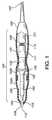
本発明に従って使用される超音波ドライバーは、超音波装置の当業者に知られている。しかしながら、一例として、典型的な超音波ドライバー100を備えた本発明の一実施形態を図1に示す。ドライバー100は、先端部104と基端部106とを有する概ね管状の本体102から構成されている。キャビティー108は、先端部102と基端部104との間で本体102を通って伸びている。本体102は、好ましくは、基端本体端部102bに接続された先端本体端部102aを、具備している。そのような二部分本体は、ドライバー100の構成を容易にする。 Ultrasonic drivers used in accordance with the present invention are known to those skilled in the art of ultrasonic equipment. However, as an example, one embodiment of the present invention with a typical
超音波ドライバーユニット111は、キャビティー108の長さに沿って伸びている。先端部104は、ドライバーユニット111の上のトンネラーヘッド110が、キャビティー108の内側から、本体102の外側まで伸びることができるように、開口109を具備している。トンネラーチップ112は、本体102から頭部110の最先端まで、先端側に伸びている。基端部106は、ドライバーユニット111に電源を供給するための電力線の接続部を、具備している。 The
電力線105を用いて、電気エネルギー、すなわち、駆動電流が、(図6に例示された、電源600として更に詳細を以下で述べる)ドライバー100に近接した電源から、供給された動力が、装置の先端部で頭部110に超音波の縦方向の動きを与えるドライバー100に、送られる。動力が超音波ドライバー100に適用されたとき、(更に詳細を以下で述べる)アッセンブリは、ヘッド110に、(例えば、おおよそ40kHzの)縦方向の振動をもたらす。縦方向の動きの量は、使用者によって調整可能に選択されながら加えられた駆動力(電流)の量と共に比例して、変化する。 Using the
そのような頭部110の超音波振動は、チップ112が、組織と接触するときに、熱を発生させ、すなわち、組織を通るチップ112の動きが、頭部110のチップ112で(そして、それ故、トンネラーチップで)、動いている頭部の機械エネルギーを、非常に局部で、熱エネルギーに変換する。この局部的な熱は、狭い地域の凝固を形成し、それは、直径で1ミリメートルより小さい血管のように、細い血管の出血を減少させるか又は削除する。止血の程度は、加えられた駆動力のレベル、外科医によって加えられたトンネル力、組織タイプの性質及び他の因子との間の組織の血管、と共に変化する。チップ112での超音波振動は、結果として摩擦を減少させて、外科医が、小さい力でトンネリングすることをもたらす。 Such ultrasonic vibration of the
図1に示すように、適切な超音波ドライバー100の例は、電気エネルギーを機械的エネルギーに変換し、変換器の端部の縦方向の振動運動を結果としてもたらす圧電変換器115を、収容している。この実施形態における変換器115は、従来技術に従っており、スタックに沿って、いくつかの点に位置された運動ゼロ点を有するセラミック圧電要素のスタックの形態である。変換器スタックは、2つのシリンダー120と121との間に設けられている。シリンダー130は、シリンダー120に取り付けられており、それは、同様に、別の運動ゼロ点135でハウジングに設けられている。ホーン140は、その基端側でゼロ点135に取り付けられており、その先端側で、頭部110カプラー150に取り付けられている。頭部110は、カプラー150に加えられている。結果として、頭部110は、変換器115と共に、超音波振動数速度で、縦方向に振動する。 As shown in FIG. 1, an example of a suitable
ドライバー100の部分は、その組合せが、同じ共振周波数で振動するようにデザインされている。特に、その要素は、好ましくは、要素のそれぞれの長さが、結果として1/2波長となるように調整される。縦方向の前後運動は、音響学的取り付けホーン140の頭部110により近い直径が、減少するにつれて、増幅される。このように、ホーン140及びカプラー150は、頭部110の動きを増幅し、且つ、音響系の残部と共鳴状態にあるような調和振動を提供するような形状及び寸法であり、それは、頭部110の近くで音響学的取り付けホーン140の端部の最大前後運動を、引き起こす。 The portion of the
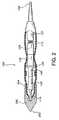
図2は、頭部110が、トンネラーチップ200によって覆われている本発明の別の実施形態を示す。この実施形態において、チップ200は、ドライバー100の残部から取り外し可能である。チップ200は、組織を通す動きを容易にする、概ね円錐形状の先端202と、ユニット100の先端部104を覆ってチップ200の挿入を容易にする開口基端部204と、を有している。 FIG. 2 shows another embodiment of the present invention in which the
更に別の実施形態において、頭部110及びトンネラーチップ200は、全体頭部300で図3に示されるような、単一全体部品の形態にできる。いずれにしても、頭部110及びトンネラーチップ200(又は単に頭部300)が、当業者に知られた手段を介してドライバー100に取り付けられている。 In yet another embodiment, the
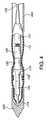
図4は、トンネラー400の端部に取り付けられた図2の装置を示す。本発明に従って使用されたトンネラーは、当業者に知られている。トンネラーは、ねじ接続を具備している公知手段によって、チップに接続されている。図5は、トンネラー400が、ドライバー100に沿って更に伸びている、別の実施形態を示す。更に別の実施形態において(図示せず)トンネラーは、ドライバー100に沿って更にいっそう伸びることができ、全ドライバー100がチップ200によって覆われた部分を除いて、トンネラー内に含まれるように、チップ200と、接触できる。 FIG. 4 shows the device of FIG. 2 attached to the end of the
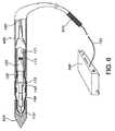
図6は、電源600に接続された図5のドライバーを例示する。電源600は、当業者に知られている超音波駆動電源と一致する。電源600は、電力線105に、制御可能な電流を供給する。使用者が、操作中にトンネラーをつかんで制御するためのハンドルを具備している。 FIG. 6 illustrates the driver of FIG. 5 connected to a
図7は、トンネラー400が、ドライバー700にねじで接続されている本発明の実施形態を示す。上述したように、電力線105は、チップ315を振動させ且つ駆動させる変換器115に、電流を供給する。 FIG. 7 shows an embodiment of the invention in which the
図8は、超音波ドライバー100が、完全にトンネラー800の内部に配置された更に別の実施形態を示す。トンネラー800は、先端部804と基端部806とを有する本体802を具備している。キャビティー808は、先端部804と基端部806との間で、本体802の内部に伸びている。本実施形態において、頭部110は、トンネラー800が、使用中に組織を通って進められるとき、組織接触点で超音波エネルギーを提供するのに十分なトンネラー800の先端部804における開口809まで伸びている。 FIG. 8 shows yet another embodiment in which the
本発明の更に別の実施形態において、トンネラーチップにおける解剖用組織のための手段を、上述したように超音波エネルギーの代わりに直流電流によって提供することができる。本実施形態において、図9に例示したように、二極チップ900が、トンネラー910の先端部で露出されている。トンネラー910は、先端部904と基端部906とを有する本体902を具備している。キャビティー908は、先端部904と基端部906との間で、本体902の内部に伸びている。二極の導体リード線915、920は、キャビティー908を通って伸びており、且つ、先端チップ912で本体902からわずかに先端側に伸びている。二極の導体リード線915及び920は、それらの先端部領域で互いに関して同軸であるが、基端部では、分離されている。導体リード線915及び920は、(先端部の方へ)同軸の領域にわたって、同軸の絶縁体(図示せず)によって分離されている。 In yet another embodiment of the present invention, means for anatomical tissue at the tunneler tip can be provided by direct current instead of ultrasonic energy as described above. In the present embodiment, as illustrated in FIG. 9, the
図10は、トンネラー940にねじ接続されている二極のトンネラーチップ930を有している実施形態を示す。各導体リード線915及び920の基端部は、電源ライン950で電気的に接触している。これら二極チップは、外科用ペンシル及び焼灼装置を使用する当業者に知られている。しかしながら、本発明は、組織を通るトンネラーの前進中に、組織層を分離するために電気エネルギー供給を利用する。本発明は、単極チップも使用可能であり、その構成は当業者に知られている。上述したように、組織層分離と共に、焼灼及び外傷の減少を具備している、いくつかの利点が理解される。上述のように、組織を通ってトンネラーが進むために、小さな力がオペレーターによって必要とされる。 FIG. 10 illustrates an embodiment having a
図11は、超音波ドライバー100が、装置のハンドル610に配置され、且つ、頭部110が、トンネラー400の全体にわたって伸びている、更なる実施形態を例示する。図11に示された装置の先端は、図2〜6の実施形態において示されたような円錐チップを有していないが、その先端部に配置されたそれらチップのいずれかを有することができる。上述したように、そのような円錐チップは、頭部110に取り付けられるか又は頭部110の一部分として形成されることができる。更に、上記開示された実施形態のいずれかの組合せは、この開示を読んでいる当業者によって理解される。 FIG. 11 illustrates a further embodiment in which the
本発明に従ったトンネラー及びチップの材料は、通常はステンレス鋼である。しかしながら、他の可能性のある材料が超音波及びトンネル技術の分野の当業者によって知られている。 The material of the tunneler and tip according to the present invention is usually stainless steel. However, other possible materials are known by those skilled in the field of ultrasound and tunnel technology.
本発明には、上述した装置を使用する方法も具備されている。特に、本発明に従った方法は、トンネル装置が組織を通って進められたときに、トンネル装置のチップで、生体組織層及び分離組織層の中にトンネル装置を進めるステップを具備している。この方法は、上述した装置の使用と一致する。組織は、エネルギー、好ましくは、上述したように、超音波エネルギー又は直流エネルギーの供給に従って焼灼される。しかしながら、トンネル処置は、概ね、当業者に知られている。しかしながら、ここに開示した方法の利点は、上記で開示されており、減少した外傷、減少した回復時間、高い患者の快適性、少ない痛み及びトンネル処置を行う人の使用の簡略性を具備している。これらの利点は、この方法及び開示された装置を使用することを通して達成され、トンネラーの先端チップでエネルギー(好ましくは、超音波又は直流エネルギー)の供給の結果、導かれる。 The present invention also includes a method of using the apparatus described above. In particular, the method according to the invention comprises the step of advancing the tunnel device into the biological tissue layer and the separated tissue layer at the tip of the tunnel device as the tunnel device is advanced through the tissue. This method is consistent with the use of the device described above. The tissue is ablated according to a supply of energy, preferably ultrasonic energy or direct current energy, as described above. However, tunneling is generally known to those skilled in the art. However, the advantages of the method disclosed herein are disclosed above, with reduced trauma, reduced recovery time, high patient comfort, less pain and simplicity of use for the person performing the tunneling procedure. Yes. These advantages are achieved through the use of this method and the disclosed apparatus and are derived as a result of the supply of energy (preferably ultrasound or direct current energy) at the tunneler tip.
本発明は、特定の実施形態に関してここに図示され、記述されているが、本発明は、示された詳細に限定されることを意図したものではない。更に、種々の変形が、請求項の同等の範囲及び領域内において、発明から逸脱することなく作られる。 Although the invention is illustrated and described herein with reference to specific embodiments, the invention is not intended to be limited to the details shown. In addition, various modifications can be made within the scope and range of the claims without departing from the invention.
Claims (17)
Translated fromJapanese先端部(104、904)と基端部(106、906)とを有する管状本体(102、902)と、
前記管状本体(102、902)の前記先端部(104、904)に配置された先端チップ(112、912)と、
前記先端チップ(112、912)に近接した組織細胞に組織分離エネルギーを供給する手段と、を備えたことを特徴とするトンネル機器。Tunnel equipment,
A tubular body (102, 902) having a distal end (104, 904) and a proximal end (106, 906);
A tip (112, 912) disposed at the tip (104, 904) of the tubular body (102, 902);
Means for supplying tissue separation energy to tissue cells proximate to the tip (112, 912).
前記チップ本体(200)が、前記チップ本体(200)の前記先端部(202)に超音波エネルギーを供給する超音波ドライバー(111)を備えている、請求項1記載のトンネル機器。The distal tip (112) is composed of a main body (200) having a conical distal end (202) and a proximal end (204),
The tunnel device according to claim 1, wherein the chip body (200) includes an ultrasonic driver (111) for supplying ultrasonic energy to the tip portion (202) of the chip body (200).
前記ハンドル(610)が、前記先端チップ(112)に前記組織分離エネルギーを提供するための超音波ドライバー(111)を収容している、請求項1記載のトンネル機器。A handle (610) disposed proximate to the proximal end (106) of the body (102);
The tunnel device of claim 1, wherein the handle (610) houses an ultrasonic driver (111) for providing the tissue separation energy to the tip (112).
内部にキャビティー(808)を配置した本体(802)と、
前記キャビティー(808)内で、本体組織に、組織分離エネルギー(100)を供給する手段と、を備えていることを特徴とするトンネラーチップ。A tunneler tip for use in surgical tunnel equipment,
A body (802) having a cavity (808) disposed therein;
Means for supplying tissue separation energy (100) to the body tissue in the cavity (808).
先端部(104、904)と基端部分(106、906)とを有する管状本体(102、902)と、
本体(102、902)内に実質的に位置付けられ、且つ、本体(102、902)の先端側に伸びている先端チップ(112、912)を有している、熱発生装置(111、900)と、を備えていることを特徴とするトンネラー。A tunneler,
A tubular body (102, 902) having a distal end (104, 904) and a proximal portion (106, 906);
A heat generating device (111, 900) having a tip (112, 912) positioned substantially within the body (102, 902) and extending to a tip side of the body (102, 902) And a tunneler characterized by comprising:
Applications Claiming Priority (2)
| Application Number | Priority Date | Filing Date | Title |
|---|---|---|---|
| US10/913,266US20060030871A1 (en) | 2004-08-05 | 2004-08-05 | Vascular tunneler |
| PCT/US2005/027880WO2006015384A1 (en) | 2004-08-05 | 2005-08-03 | Vascular tunneler |
Publications (1)
| Publication Number | Publication Date |
|---|---|
| JP2008508949Atrue JP2008508949A (en) | 2008-03-27 |
Family
ID=35758397
Family Applications (1)
| Application Number | Title | Priority Date | Filing Date |
|---|---|---|---|
| JP2007525026AWithdrawnJP2008508949A (en) | 2004-08-05 | 2005-08-03 | Vascular tunneler |
Country Status (5)
| Country | Link |
|---|---|
| US (1) | US20060030871A1 (en) |
| EP (1) | EP1796640A1 (en) |
| JP (1) | JP2008508949A (en) |
| CA (1) | CA2575695A1 (en) |
| WO (1) | WO2006015384A1 (en) |
Cited By (1)
| Publication number | Priority date | Publication date | Assignee | Title |
|---|---|---|---|---|
| WO2014136147A1 (en) | 2013-03-08 | 2014-09-12 | ディーブイエックス株式会社 | Intracorporeal introduction instrument |
Families Citing this family (11)
| Publication number | Priority date | Publication date | Assignee | Title |
|---|---|---|---|---|
| RU2548918C2 (en) | 2009-02-24 | 2015-04-20 | Медивэйшн Простейт Терапьютикс, Инк. | Specific diarylhydantoin and diarylthiodiaryl compounds |
| US20100305428A1 (en)* | 2009-05-29 | 2010-12-02 | Medtronic, Inc. | Ultrasonic guidance of subcutaneous tunneling |
| US20140188148A1 (en) | 2012-12-27 | 2014-07-03 | Pieter W.C.J. le Blanc | Surgical tunneler |
| US9924962B2 (en) | 2015-10-08 | 2018-03-27 | Olympus Corporation | Elbow joint surgical treatment |
| US10028755B2 (en) | 2015-10-08 | 2018-07-24 | Olympus Corporation | Knee joint surgical treatment |
| US10052118B2 (en) | 2015-10-08 | 2018-08-21 | Olympus Corporation | Knee joint surgical treatment |
| US10080577B2 (en) | 2015-10-08 | 2018-09-25 | Olympus Corporation | Joint surgical treatment |
| US10052119B2 (en) | 2015-10-08 | 2018-08-21 | Olympus Corporation | Knee joint surgical treatment |
| US10383642B2 (en) | 2015-10-08 | 2019-08-20 | Olympus Corporation | Surgical procedure of knee joint |
| US10052117B2 (en) | 2015-10-08 | 2018-08-21 | Olympus Corporation | Joint surgical treatment |
| US20180116784A1 (en) | 2016-10-28 | 2018-05-03 | Olympus Corporation | Surgical procedure of knee joint |
Family Cites Families (25)
| Publication number | Priority date | Publication date | Assignee | Title |
|---|---|---|---|---|
| US3805787A (en)* | 1972-06-16 | 1974-04-23 | Surgical Design Corp | Ultrasonic surgical instrument |
| US3974833A (en)* | 1973-03-19 | 1976-08-17 | Durden Iii John G | Disposable electrosurgical cautery having optional suction control feature |
| US5013312A (en)* | 1990-03-19 | 1991-05-07 | Everest Medical Corporation | Bipolar scalpel for harvesting internal mammary artery |
| US5843017A (en)* | 1990-07-24 | 1998-12-01 | Yoon; Inbae | Multifunctional tissue dissecting instrument |
| US5658307A (en)* | 1990-11-07 | 1997-08-19 | Exconde; Primo D. | Method of using a surgical dissector instrument |
| CA2060067A1 (en)* | 1991-01-28 | 1992-07-29 | Lilip Lau | Stent delivery system |
| US5391172A (en)* | 1993-05-24 | 1995-02-21 | Advanced Cardiovascular Systems, Inc. | Stent delivery system with coaxial catheter handle |
| US5472447A (en)* | 1994-05-03 | 1995-12-05 | Abrams; Andrew L. | Power-assisted obturator |
| US6015429A (en)* | 1994-09-08 | 2000-01-18 | Gore Enterprise Holdings, Inc. | Procedures for introducing stents and stent-grafts |
| US5653726A (en)* | 1994-11-03 | 1997-08-05 | Archimedes Surgical, Inc. | Retrograde dissector and method for facilitating a TRAM flap |
| DE69633411T2 (en)* | 1995-10-13 | 2005-10-20 | Transvascular, Inc., Menlo Park | METHOD AND DEVICE FOR PREVENTING ARTERIAL ATTRACTIONS AND / OR FOR CARRYING OUT OTHER TRANSVASCULAR INTERVENTIONS |
| US5968068A (en)* | 1996-09-12 | 1999-10-19 | Baxter International Inc. | Endovascular delivery system |
| US6010449A (en)* | 1997-02-28 | 2000-01-04 | Lumend, Inc. | Intravascular catheter system for treating a vascular occlusion |
| US5879363A (en)* | 1997-03-18 | 1999-03-09 | Circuit Tree Medical, Inc. | Disposable surgical ultrasonic transducer |
| US6565594B1 (en)* | 1997-09-24 | 2003-05-20 | Atrium Medical Corporation | Tunneling device |
| US6014589A (en)* | 1997-11-12 | 2000-01-11 | Vnus Medical Technologies, Inc. | Catheter having expandable electrodes and adjustable stent |
| US6081738A (en)* | 1998-01-15 | 2000-06-27 | Lumend, Inc. | Method and apparatus for the guided bypass of coronary occlusions |
| US6196230B1 (en)* | 1998-09-10 | 2001-03-06 | Percardia, Inc. | Stent delivery system and method of use |
| US6149596A (en)* | 1998-11-05 | 2000-11-21 | Bancroft; Michael R. | Ultrasonic catheter apparatus and method |
| US6461383B1 (en)* | 1999-12-30 | 2002-10-08 | Advanced Cardiovascular Systems, Inc. | Ultrasonic catheter vascular stent system and method |
| US6537291B2 (en)* | 2000-10-20 | 2003-03-25 | Ethicon Endo-Surgery, Inc. | Method for detecting a loose blade in a hand piece connected to an ultrasonic surgical system |
| US6679899B2 (en)* | 2000-10-20 | 2004-01-20 | Ethicon Endo-Surgery, Inc. | Method for detecting transverse vibrations in an ultrasonic hand piece |
| US6678621B2 (en)* | 2000-10-20 | 2004-01-13 | Ethicon Endo-Surgery, Inc. | Output displacement control using phase margin in an ultrasonic surgical hand piece |
| WO2005025439A2 (en)* | 2002-11-15 | 2005-03-24 | San Diego Swiss Machining, Inc. | Ultrasonic dental tip with waterguide design |
| US7566318B2 (en)* | 2003-04-11 | 2009-07-28 | Cardiac Pacemakers, Inc. | Ultrasonic subcutaneous dissection tool incorporating fluid delivery |
- 2004
- 2004-08-05USUS10/913,266patent/US20060030871A1/ennot_activeAbandoned
- 2005
- 2005-08-03EPEP05802953Apatent/EP1796640A1/ennot_activeWithdrawn
- 2005-08-03CACA002575695Apatent/CA2575695A1/ennot_activeAbandoned
- 2005-08-03WOPCT/US2005/027880patent/WO2006015384A1/enactiveApplication Filing
- 2005-08-03JPJP2007525026Apatent/JP2008508949A/ennot_activeWithdrawn
Cited By (1)
| Publication number | Priority date | Publication date | Assignee | Title |
|---|---|---|---|---|
| WO2014136147A1 (en) | 2013-03-08 | 2014-09-12 | ディーブイエックス株式会社 | Intracorporeal introduction instrument |
Also Published As
| Publication number | Publication date |
|---|---|
| WO2006015384A8 (en) | 2006-04-06 |
| EP1796640A1 (en) | 2007-06-20 |
| CA2575695A1 (en) | 2006-02-09 |
| WO2006015384A1 (en) | 2006-02-09 |
| US20060030871A1 (en) | 2006-02-09 |
Similar Documents
| Publication | Publication Date | Title |
|---|---|---|
| US7717913B2 (en) | RF cauterization and ultrasonic ablation instrument with multi-hole collar and electrode mounting sleeve | |
| US8287485B2 (en) | Treatment system for surgery and control method of treatment system for surgery | |
| US7223267B2 (en) | Ultrasonic probe with detachable slidable cauterization forceps | |
| US6736814B2 (en) | Ultrasonic medical treatment device for bipolar RF cauterization and related method | |
| US5989274A (en) | Methods and devices for improving blood flow to a heart of a patient | |
| US6902536B2 (en) | Ultrasonic medical treatment device for RF cauterization and related method | |
| CN101420914B (en) | Multi-function device for endoscopic surgery | |
| US8632560B2 (en) | System for breaking up thrombi and plaque in the vasculature | |
| US6926717B1 (en) | Electrosurgical breast electrode | |
| US20080194999A1 (en) | Ultrasonic treatment apparatus and treatment method | |
| EP2438876A1 (en) | Electrosurgical Cobb Elevator Instrument | |
| JPH09140722A (en) | Ultrasonic therapy instrument | |
| US20110306997A9 (en) | Devices for creating passages and sensing for blood vessels | |
| JPH10511030A (en) | Vascular tissue sealing pressure control device and control method thereof | |
| JP2002500523A (en) | Method and apparatus for improving blood flow to a patient's heart | |
| JP2007500582A (en) | Electrosurgical instrument and method for selectively cutting tissue | |
| US6231578B1 (en) | Ultrasonic snare for excising tissue | |
| JP2008508949A (en) | Vascular tunneler | |
| US8109925B2 (en) | Treatment of breast disease with vibrating device | |
| US20070213681A1 (en) | Method for the treatment of peyronie's disease | |
| JP2507871Y2 (en) | Electrosurgical device electrode | |
| JP3148843U (en) | Surgical tools and surgical system | |
| JP2002136526A (en) | Wand head for electric scalpel | |
| JP3217951B2 (en) | Equipment for removing fistulas | |
| WO2019198097A1 (en) | Transvaginal non-invasive ablation of polycystic ovarian disease ( pcos) and endometriotic ovarian cysts and device thereof to carry out said function |
Legal Events
| Date | Code | Title | Description |
|---|---|---|---|
| A621 | Written request for application examination | Free format text:JAPANESE INTERMEDIATE CODE: A621 Effective date:20080804 | |
| A711 | Notification of change in applicant | Free format text:JAPANESE INTERMEDIATE CODE: A711 Effective date:20080804 | |
| A521 | Request for written amendment filed | Free format text:JAPANESE INTERMEDIATE CODE: A821 Effective date:20080804 | |
| RD04 | Notification of resignation of power of attorney | Free format text:JAPANESE INTERMEDIATE CODE: A7424 Effective date:20091228 | |
| A761 | Written withdrawal of application | Free format text:JAPANESE INTERMEDIATE CODE: A761 Effective date:20100730 |